Embed Size (px)
Citation preview

SANDIA REPORT SAND97-8245 UC-406
I . Unlimited Release Printed March 1997
w
Modification of the Sandia National Laboratories/CaIifornia Advanced Coordinate Measuring Machine for High Speed Scanning
I 3. M. Baldwin, R. D. Pilkey, R. M. Cassou, K. D. Summerhays, R. P. Henke

Issued by Sandia National Laboratories, operated for the United States Department of Energy by Sandia Corporation. NOTICE: This report was prepared as an account of work sponsored by an agency of the United States Government. Neither the United States Government nor any agency thereof, nor any of their employees, nor any of the contractors, subcontractors, or their employees, makes any warranty, express or implied, or assumes any legal liability or responsibility for the accuracy, completeness, or usefulness of any information, apparatus, product, or process disclosed, or represents that its use would not infringe privately owned rights. Reference herein to any specific commercial product, process, or service by trade name, trademark, manufacturer, or otherwise, does not necessarily constitute or imply its endorsement, recommendation, or favoring by the United States Government, any agency thereof or any of their contractors or subcontractors. The views and opinions expressed herein do not necessarily state or reflect those of the United States Government, any agency thereof, or any of their contractors or subcontractors.
This report has been reproduced from the best available copy.
Available to DOE and DOE contractors from:
Office of Scientific and Technical Information P.O. Box 62 Oak Ridge TN 37831
Prices available from (61 5) 576-8401, FTS 626-8401.
Available to the public from:
National Technical Information Service U.S. Department of Commerce 5285 Port Royal Rd. Springfield, VA 22161
.

DISCLAIMER
This report was prepared as an account of work sponsored by an agency of the United States Government. Neither the United States Government nor any agency thereof, nor any of their employees, make any warranty, express or implied, or assumes any legal liabili- ty or mponsibility for the accuracy, completeness, or usefulness of any information, appa- ratus, product, or process disclosed, or represents that its use would not infringe privately owned rights. Reference herein to any specific commercial product, process, or service by trade name, trademark, manufacturer, or otherwise does not necessarily corntitUte or imply its endorsement, recommendation, or favoring by the United States Government or any agency thereof. The views and opinions of authors expressed herein do not necessar- ily state or reflect those of the United States Government or any agency thereof.

Portions of this document may be illegible in electronic image products. Images are produced from the best available original dOl.ument

UC-406
SAND97-8245 Unlimited Release
Printed March 1997
MODIFICATION OF THE SANDIA NATIONAL LABORATORIES/CALIFORNIA ADVANCED COORDINATE MEASURING MACHINE FOR HIGH SPEED SCANNING
Jon M. Baldwin, Robert D. Pilkey Integrated Manufacturing Systems
Sandia National LaboratoriesKalifornia
Ronald M. Cassou, Kim D. Summerhays University of San Francisco
San Francisco, California
Richard P. Henke MicroVu
Windsor, California
ABSTRACT
The Moore M48V high accuracy coordinate measuring machine (CMM), while mechanically capable of exact measurement of physical artifacts, is not, in its original configuration, well suited for rapid gathering of high density dimensional information. This report describes hardware and software modifications to the original control and data acquisition system that allow relatively high speed scanning of cylindrical features. We also estimate the accuracy of the individual point data on artifacts measured with this system and provide detailed descriptions of the hardware and software apparatus as an aid to others who may wish to apply the system to cylindrical or other simple geometries.
3J4

CONTENTS Page
I . Introduction . . . . . . . . . . . . . . . . . . . . . . . . . . . . . . . . . . . . . . . . . . . . . . . . . . . . . . . . . . . . . 7
. . . . . . . . . . . . 8
III . Probing System Modifications . . . . . . . . . . . . . . . . . . . . . . . . . . . . . . . . . . . . . . . . . . . . . 11 Probe System Calibration . . . . . . . . . . . . . . . . . . . . . . . . . . . . . . . . . . . . . . . . . . . . . . . 11
IV . Artifact Fixturing and Location . . . . . . . . . . . . . . . . . . . . . . . . . . . . . . . . . . . . . . . . . . . . . 14 Description of Cylinder Artifact . . . . . . . . . . . . . . . . . . . . . . . . . . . . . . . . . . . . . . . . . . 14 Fixture Description . . . . . . . . . . . . . . . . . . . . . . . . . . . . . . . . . . . . . . . . . . . . . . . . . . . 14 Fixture Calibration . . . . . . . . . . . . . . . . . . . . . . . . . . . . . . . . . . . . . . . . . . . . . . . . . . . . 15
V . Error Budget Calculations . . . . . . . . . . . . . . . . . . . . . . . . . . . . . . . . . . . . . . . . . . . . . . . . . 19 Thermally-induced Errors . . . . . . . . . . . . . . . . . . . . . . . . . . . . . . . . . . . . . . . . . . . . . . . 19 Errorsinr . . . . . . . . . . . . . . . . . . . . . . . . . . . . . . . . . . . . . . . . . . . . . . . . . . . . . . . . . . 19
Errors due to spindle axis offset from feature axis . . . . . . . . . . . . . . . . . . . . . . . 19
I1 . Data Acquisition System Modification . . . . . . . . . . . . . . . . . . . . . . . . . . . . . . . . . . . . . . . . . 8 Description of the Original M48V Control and Data Acquisition System Modifications to Data Acquisition and Control Electronics . . . . . . . . . . . . . . . . . . . . . . . 9
Error due to varying contact point of the probe tip . . . . . . . . . . . . . . . . 19 Error due to variation of effective probe offset from spindle axis . . . . . . 24
Positioning error of x- and y-axes . . . . . . . . . . . . . . . . . . . . . . . . . . . . . . . . . . . 26 Uncertainty of indicator calibration . . . . . . . . . . . . . . . . . . . . . . . . . . . . . . . . . . 26 Error due to variation of the voltage divider ratio . . . . . . . . . . . . . . . . . . . . . . . 26 Failure of the electronic indicator to act as a one-dimensional sensor . . . . . . . . 26 Uncertainty in the x- and y-axis reference locations . . . . . . . . . . . . . . . . . . . . . . 26 Uncertainty of the probe tip radius . . . . . . . . . . . . . . . . . . . . . . . . . . . . . . . . . . 27 Total error in r . . . . . . . . . . . . . . . . . . . . . . . . . . . . . . . . . . . . . . . . . . . . . . . . . 27
Errors in 8 . . . . . . . . . . . . . . . . . . . . . . . . . . . . . . . . . . . . . . . . . . . . . . . . . . . . . . . . . . 27 Positioning error of the spindle axis . . . . . . . . . . . . . . . . . . . . . . . . . . . . . . . . . 27 Uncertainty in the zero position of the spindle axis . . . . . . . . . . . . . . . . . . . . . . 27 Total error in 8 . . . . . . . . . . . . . . . . . . . . . . . . . . . . . . . . . . . . . . . . . . . . . . . . . 27
Errorsinz . . . . . . . . . . . . . . . . . . . . . . . . . . . . . . . . . . . . . . . . . . . . . . . . . . . . . . . . . . 28 Positioning error of the z-axis . . . . . . . . . . . . . . . . . . . . . . . . . . . . . . . . . . . . . . 28 Uncertainty in the z-axis reference location . . . . . . . . . . . . . . . . . . . . . . . . . . . . 28 Variation of artifact thickness . . . . . . . . . . . . . . . . . . . . . . . . . . . . . . . . . . . . . . 28 Total error in z . . . . . . . . . . . . . . . . . . . . . . . . . . . . . . . . . . . . . . . . . . . . . . . . . 28
Summary . . . . . . . . . . . . . . . . . . . . . . . . . . . . . . . . . . . . . . . . . . . . . . . . . . . . . . . . . . . 28 VI . References . . . . . . . . . . . . . . . . . . . . . . . . . . . . . . . . . . . . . . . . . . . . . . . . . . . . . . . . . . . . 30 Appendix A: Data Acquisition Program . . . . . . . . . . . . . . . . . . . . . . . . . . . . . . . . . . . . . . . . . . 31 Appendix B: Typical Motion Control Programs . . . . . . . . . . . . . . . . . . . . . . . . . . . . . . . . . . . . 39
SCANMAIN . . . . . . . . . . . . . . . . . . . . . . . . . . . . . . . . . . . . . . . . . . . . . . . . . . . . . . . . 40 POSINCYL . . . . . . . . . . . . . . . . . . . . . . . . . . . . . . . . . . . . . . . . . . . . . . . . . . . . . . . . . 42 SCANCYL . . . . . . . . . . . . . . . . . . . . . . . . . . . . . . . . . . . . . . . . . . . . . . . . . . . . . . . . . 42
Appendix C: Machine Drawing of the Cylinder Artifact . . . . . . . . . . . . . . . . . . . . . . . . . . . . . . 44
5

ILLUSTRATIONS No. Page 1 . Schematic diagram of the original M48V data acquisition and control system . . . . . . . . . . . . 8 2 . Schematic diagram of the modified M48V data acquisition and control system . . . . . . . . . . . 9 3 . Electronic indicator mounted in the c-axis quill of the M48V
6 . Close-up view of artifact-positioning fixture . . . . . . . . . . . . . . . . . . . . . . . . . . . . . . . . . . . . 16
9 . Error in r due to varying point of probe contact; detail showing probe tip geometry . . . . . . 22
. . . . . . . . . . . . . . . . . . . . . . . 12 4 . Internal cylindrical feature artifact . . . . . . . . . . . . . . . . . . . . . . . . . . . . . . . . . . . . . . . . . . . . 14 5 . Artifact-positioning fixture and calibration hardware . . . . . . . . . . . . . . . . . . . . . . . . . . . . . . 15
7 . Fixture z-reference calibration . . . . . . . . . . . . . . . . . . . . . . . . . . . . . . . . . . . . . . . . . . . . . . . 17 8 . Error in r due to varying point of probe contact . . . . . . . . . . . . . . . . . . . . . . . . . . . . . . . . . 20
10 . Scale of Figure 8 distorted to show geometry at the probe tip . . . . . . . . . . . . . . . . . . . . . . 23 11 . Error due to spindle axis offset; rbd=0 . . . . . . . . . . . . . . . . . . . . . . . . . . . . . . . . . . . . . . . . 24 12 . Cylinder artifact; top view . . . . . . . . . . . . . . . . . . . . . . . . . . . . . . . . . . . . . . . . . . . . . . . . . 45 13 . Cylinder artifact; bottom view . . . . . . . . . . . . . . . . . . . . . . . . . . . . . . . . . . . . . . . . . . . . . . 46 14 . Cylinder artifact; side view . . . . . . . . . . . . . . . . . . . . . . . . . . . . . . . . . . . . . . . . . . . . . . . . 47 15 . Cylinder artifact; section view . . . . . . . . . . . . . . . . . . . . . . . . . . . . . . . . . . . . . . . . . . . . . . 47 16 . Cylinder artifact; detail A . . . . . . . . . . . . . . . . . . . . . . . . . . . . . . . . . . . . . . . . . . . . . . . . . 48 17 . Cylinder artifact; detail B . . . . . . . . . . . . . . . . . . . . . . . . . . . . . . . . . . . . . . . . . . . . . . . . . 49 18 . CyIinder artifact; detail C . . . . . . . . . . . . . . . . . . . . . . . . . . . . . . . . . . . . . . . . . . . . . . . . . 50
TABLE . No . Page C.1 . List of full cylindrical features on the artifact . . ~ I . . . . . . . ~ . . . . . ~ . ~ ~ . . . . . ~ . . . . . 51
6
MODIFICATION OF THE SANDIA NATIONAL LABORATORIES/CALIFORNIA ADVANCED COORDINATE MEASURING MACHINE FOR HIGH SPEED SCANNING
I. Introduction
The installation and capabilities of the Moore M48V coordinate measuring machine (CMM) at Sandia National Laboratories, Livermore, California have been described in an earlier report [ 13. As normally configured, the M48V is equipped with a 3D analog probe head with 3 axis position sensing capability and can perform three-dimensional measurements of artifacts up to 1220 mm x 813 mm x 508 mm (48 in x 32 in x 20 in) in size with a typical volumetric uncertainty of 1.5 pm (60 pin) over the measuring volume. Complete performance specifications are given in the above-referenced report. A major limitation of the M48V CMM as originally installed is a low maximum data acquisition rate, about one point per 10 seconds. The original system is thus unsuited for the rapid acquisition of high density dimensional information. Additionally, the standard probing system has a relatively narrow linear dynamic range, *0.050 mm (0.002 in), rendering impossible automated measurement of features with errors approaching that value.
Recent collaborative research, involving workers from Sandia National Laboratories, California, the University of San Francisco and Allied SignaVFederal Manufacturing &Technology Division, has been directed at investigating efficient and accurate methods for sample pattern selection and data analysis in point-sample methods of dimensional metrology [2-41. Key to the success of that work has been the acquisition of high density (= lo3 to lo4 pointdfeature) data on series of nominally identical machined metal artifacts.
W i l e the M48V is ideally suited to this work from the point of view of accuracy and resolution, the achievable data rate was obviously a prohibitive factor. Additionally, the linear dynamic range of the standard probing system is readily exceeded by many machined surfaces. This report describes modifications to the M48V probing system and data acquisition electronics which relieve these limitations for simple (cylindrical, planar) feature geometries. Following sections of this report describe: a) modifications to the original sensing and data acquisition systems, b) software for CMM control and data acquisition, c) fixturing and datum establishment for artifacts with internal cylindrical features and d) error budget calculations. We also present detailed information on data gathering and motion control programs as well as on the design of the artifact.
7

II. Data Acquisition System Modification
Description of the Original M48V Control and Data Acquisition Systems
These systems are described more completely in the earlier report [l]. The following brief description is provided to set the context for the current modifications.
The original control and data acquisition systems are shown schematically in Figure 1. In normal operation, machine control instruction files are created in the Hewlett Packard 330 Series computer and transmitted over a serial connection to the Allen Bradley Series 8200 CNC controller, which drives analog servo amplifiers and, in turn, the machine x-, y-, z- and c-axis servo motors.
1 , MOORE M48V CMM
ZYGU LASER INTERFEROMETER
ANALOG PROBE HEAD
86030 W O R K S T A T I O N 3-
I I
I I
1. M o t o r D r i ve
2. A Quad B Signals
3. Analog Signal
Signals
f r o m Sca les
f r o m Scanning P r o b e
4. Combined Posi t ion Signal via I E E E - 488 I n t e r f a c e
5. RS-232' Link f o r CMM C o n t r o l
I I
Figure 1. Schematic diagram of the original M48V data acquisition and control system.
Machine position information is provided, for the linear axes, by vacuum-path laser interferometers. Spindle axis angular information is provided by a rotary encoder with a resolution of 3D probe deflection information, to an embedded processor which provides probe contact detection and position feedback to the Allen Bradley controller via a serial connection and part dimensional information to the Hewlett Packard computer through an IEEE-488 connection. It is a significant feature of the original design that absolute reference indications are not available for any of the machine axes. This limitation persists in the modified system and necessitates much of the calibration described in sections to follow,
revolution (0.0036 deg.). The axis position information is delivered, along with
8

Geometric data are processed and measurement reports generated with software executing on the Hewlett Packard computer. The maximum data rate capability of this system is approximately one point per 10 seconds, with the response characteristics of the Tridim probe, the maximum machine speed while probing and the processing power of the Hewlett Packard computer being
-, the major limiting factors.
-[>
Modifications to Data Acquisition and Control Electronics
J
ALLEN-BRADLEY CONTROLLER OPTO-ISOLATED 6
The modified data acquisition and control system is shown in Figure 2. All of the major data rate limiting elements of the original system have been replaced.
The original motor drives were retained, along with the Allen Bradley controller. Motion control programs were written in the Allen Bradley control language [ 5 ] , either by direct keypad entry at the Allen Bradley control panel or with a text editor running on the 80386-based computer, in which case they were subsequently uploaded to the controller over the serial link.
1 + 2 -
MOORE M48V CMM
ZYGO LASER INTERFEROMETER
FEDERAL ELECTRONIC INDICATOR
(IN SPINDLE)
c"
I 80386 E COMPUTER E E
4 8 8 BUS 1
-
I DIGITAL I
1. Motor Drive Signals
2. A Quad B Signals f rom Scales
3. Digi ta l Posi t ion f r o m Scales
4, Analog D e f l e c t - ion f r o m Federal I n d i c a t o r
5. RS-232 Link 6. + / - 12 V o l t
Digital I n p u t on Second RS-232 P o r t C o n t r o l Line
Figure 2. Schematic diagram of the modified M48V data acquisition and control system.
The original probing system was replaced by a Federal electronic indicator mounted in the rotary spindle. The analog output of the electronic indicator was divided by a thin film resistor divider to match the ranges available on the Hewlett Packard Model 3437A digital voltmeter. The voltage divider had a nominal total resistance of 20 Ksz and was calibrated with a precision voltage source and a digital voltmeter having a resolution of 1: lo7 of full scale. Thermally-induced resistance fluctuations due to varying power dissipation were a matter for concern. Readings were taken at
9

applied voltages of one and five volts (nominally, currents of 0.05 and 0.25 ma), waiting in each case for the voltage reading at the divider tap to stabilize. Divider ratios of 0.400276~0.000001 and 0.400273~0.000002, respectively, were observed. The uncertainty in the divider ratio is thus seen to be on the order of 2: 1 05, inclusive of thermal effects. The voltmeter digital output, corresponding to the radial deflection of the indicator, was transmitted over the IEEE-488 bus to the data collection computer.
Axis position data for the linear axes was transmitted from the laser interferometer to the data collection computer over the same EEE-488 bus. In order to maximize data throughput the x- and y-axis positions were read only once per commanded z-axis move and assumed to be constant throughout the move while the c-axis position was assumed to be equal to the commanded position. These measures are not believed to significantly affect the accuracy of the results in view of the observed accuracy of the CMM [ 11 and the small following errors consistently observed (1-2 pin for the linear axes and 1-2 x data collection was solely along the z-axis. Under these conditions the maximum data acquisition rate was about 80 @,€I) pairs/second. Data synchronization with the z-axis scan was achieved by using coolant odoff commands in the motion control program to toggle the solid state relay which, in turn, applied a *12 v signal to one of the control lines of a second serial port.
revolution for the c-axis). Scanning during
Typical CMM motion control and data acquisition programs are presented in Appendix B of this report.
10

m. Probing System Modifications
The standard probing system used with the M48V is a Movomatic Tridimm 3-directional analog sensor with a display resolution in each axis of about 0.025 pm (1 pin). While capable of more than adequate accuracy for the present work, the mechanical response time of this probe and the electrical response of its associated data processing electronics constitute a major limiting element for the rate of data acquisition.
The simple shapes (planar, cylindrical) of interest in the present work, together with the CMM’s rotating spindle (not normally used in conjunction with the Tridim probe) permit substitution of a single-axis electronic indicator. The indicator and mounting are shown in Figure 3. The indicator used in this work was a Federal Model A-D-433 1 maximum reciprocal sensitivity of 10 pin/v. In this work, it was used at a sensitivity of 200 pidv giving a linear dynamic range of kO.001 in. While not capable of the dimensional performance of the standard probing system, this will be shown to be more than adequate for the present study.
A separate mechanical setup of the electronic indicator was required for each nominal hole size. The offset of the indicator, relative to the spindle axis of rotation, was adjusted to give an approximately zero indicator output while sweeping a ring gage of the same size as the nominal hole with the spindle coaxial to the ring gage. Generally then, all holes of a given nominal size were scanned in the same measurement run.
Probe System Calibration
It was necessary to calibrate four aspects of the modified probing system.
First, the spindle axis position of zero rotation must be coincident with the direction of one of the Cartesian machine axes. This was accomplished by rotating the spindle either manually or by move commands entered from the controller console with the indicator bearing against a flat surface (gage block) mounted parallel to one of the Cartesian planes and with the indicator analog meter at maximum sensitivity, until maximum deflection was observed. The spindle axis count was zeroed at that point.
Second, it was necessary to know the linear deflection sensitivity of the indicator. This was determined by moving the indicator through its full range against the same flat surface as used to determine the c-axis zero position and observing the digital voltmeter signal as a function of linear axis position. The laser interferometer indication was taken to be accurate in this step. The least squares computed slope of output voltage vs. position typically had a relative standard deviation 0fi:iooo (st2~10-7in/v).
Third, the radius of the spherical probe tip was measured with a laser micrometer to an estimated uncertainty of *15 pin.
11

I
Figure 3. Electronic indicator mounted in the c-axis quill of the M48V.
12

Finally, it was necessary to know the indicator sweep radius for an output of 0 V with the indicator suitably set for the nominal hole size of the current experiment. This was determined by sweeping a ring gage of a size equal to the nominal hole size. Generally, the ring gage diameter was known to *OS pm. The spindle was first centered on the ring gage by looking for the point of constant deflection while manually sweeping the ring. Eight voltage readings were then taken at equal angular intervals on the gage and a least squares circle fitted to the data, thereby providing an estimate of the desired quantity. These measurements were taken with the indicator analog meter set for *0.001 in fill scale, no voltage divider and reading the voltage with an Hewlett Packard 3455A high resolution voltmeter.
The variation in indicator reading as the ring gage is swept can be approximated as
Ar = rRING - rFED +Acos 6 + B sin 8
where r,, is the radius of the ring gage, r,, is the sweep radius of the electronic indicator, 8 is the angle of rotation of the spindle and r,,, A and B are parameters to be determined. If
then
Ar=D +Acos6 +Bsin8
which we can fit, in the least squares sense, to the observed data to get an estimate of D and thereby of r,, The standard deviation of B by this method was typically 2 pin giving a total uncertainty in r , , of about h2.5 pin.
13
IV. Artifact Fixturing and Location
Description of Cylinder Artifact
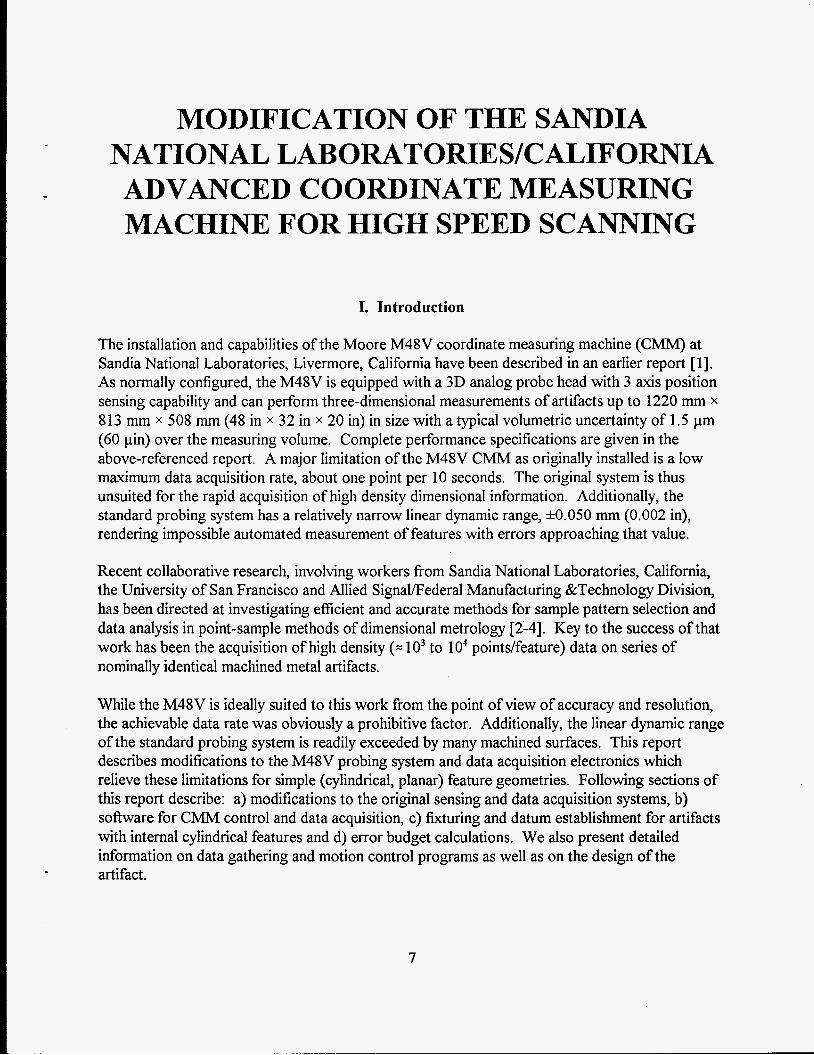
The initial subject of this work was a series of 30 nominally identical artifacts intended to provide machining process characteristics data on internal cylindrical features. The artifact design is shown schematically in Figure 4. It contains 50 full internal cylindrical features, through, blind and counterbored, of various sizes and depths, and produced by a variety of machining techniques. All holes were started with a center drill operation, followed by drilling to near nominal size. Some of the holes were further finished by reaming, boringreaming, plunge end milling, or peripheral milling. Full specifications of the artifact are given in Appendix C.
Figure 4. Internal cylindrical feature artifact.
Fixture Description
The artifact fixturing arrangement is shown in Figures 5 and 6. The bottom surface of each artifact was mechanically deburred against a granite surface plate prior to measurement. That surface was located against 3-0.0100 in gage blocks which were, in turn, fixed with epoxy cement to a set of 6 in precision parallels placed on the measuring machine table. Part alignment and x-y
14

. -.
Figure 5. Artifact-positioning fixture and calibration hardware. location were provided by 3 cylindrical pins fixed in the t-slots of the parallels. Two of these pins were mechanically aligned with the measuring machine y-axis.
Fixture Calibration
Given the lack of an absolute machine reference, it was necessary to express the motion control program relative to a fuced location on the artifact and then to accurately establish the location of the artifact relative to the current machine scale zero points.
An x-y location in the machine's coordinate system was established by assuming the first artifact (serial #002) to be typical of the entire production run. The lower 0.375 in dia reference hole was located in the machine's coordinate system by placing the artifact in the fixture, manually indicating its location with the electronic indicator and noting the x and y scale readings. These readings were recorded and entered as parameters of the motion control program (see Appendix B: Typical Motion Control Programs). Even though the pair of reference holes were specified as a machining datum they were not of particularly better form (roundness =: 0.0005 in) than the other cylindrical features and therefore constitute a significant source of error in measured feature locations.
15

Figure 6. Close-up view of artifact-positioning fiiture.
Note that this operation must precede the mechanical adjustment and calibration of the probe described under Probe System Callibration.
A z-axis reference was computed as the machine coordinate system location of the top surface of artifact w2 when in position in the fixture. A V-block with an included angle of approximately 90" was measured on a utility (0.0001 in resolution) coordinate measuring machine and found to have an included angle of 26 = 89.950 & 0.001 O and a distance from the bottom of the V-groove to the base of d = 0.4404 f 0.0002 in (standard deviation). The block was then aligned with the machine x-axis and fEed to the top of the parallel. Refer to Figure 7. The spindle was rotated so that the indicator sensitive direction was parallel to the machine y-axis, the machine y location adjusted to null the indicator against one face of the V and the y- and z-axis positions noted. The spindle was then rotated 180" and the process repeated at the other face and the same xz location. Then if the probe tip radius is r,,, , the difference of the y-axis coordinates of the probe tip center locations is Ay, the half angle of the V-block is 8, the remaining quantities are as defined in Figure 7 and we take the symmetry plane of the V to be perpendicular to the base we can calculate the total width of the V at the center of the probe tip:
16

H
1
~ d
1
1, = rbd,/cosO, 1, = rM,/cosO,
1, = 1, = rball/cos 0
Figure 7. Fixture z-reference calibration.
Then if Aym is the indicated difference in y-axis position at the two null locations and r , , is the sweep radius of the indicator as determined earlier
'Y = 'YAB -k ( rFED - rball
17
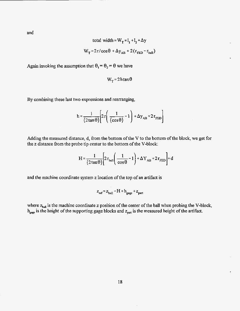
and total width = WT = I, + 1, + Ay
W, = 2 r/ COS 8 + Ay, + 2 ( rFED - rba,,)
Again invoking the assumption that 8, = 0, = 0 we have
WT = 2 htane
By combining these last two expressions and rearranging,
I h=--[2r( 1 F-l) 1 +Aym+2rFED (2 tan e) case)
Adding the measured distance, d, from the bottom of the V to the bottom of the block, we get for the z distance from the probe tip center to the bottom of the V-block:
1 H=--Frball( 1 - - I ) 1 +AY,+2rFED +d (2 bane) cos e
and the machine coordinate system z location of the top of an artifact is
where zbau is the machine coordinate z position of the center of the ball when probing the V-block, figdge is the height of the supporting gage blocks and %art is the measured height of the artifact.
18

V. Error Budget Calculations
It is of interest to have an estimate of the error in each of the three coordinates defining the probe point of contact with the artifact. In general, there are several sources of error in each coordinate. In most instances, we are able to estimate the worst case error. Errors that can reasonably be judged out of hand to be insignificant will not be treated. All error estimates are thought to represent the total worst-case error bandwidth. The total error in each coordinate is obtained by combining as the rms sum all the significant error sources.
It is, furthermore, interesting to consider the effect of errors in the individual point coordinates on the accuracy of derived parameters. Ideally, the individual point errors could be propagated through subsequent fitting algorithms to yield estimates of the resultant errors in the defining parameters of the fitted shapes. Such consideration is beyond the scope of this report. We will limit our consideration to enumeration of the most influential error source(s) for each defining parameter of the fitted cylinder. Extension to other simple geometries is straightforward.
Thermally-induced errors
Thermal control of the measuring machine environment was described in the earlier report [ 11. Room temperature control of rt 0.12 "C is generally achieved. The measured artifacts are fabricated from aluminum and are the system component most strongly influenced by temperature. Artifact temperature was monitored and generally was constant to better than f 0.1 "C. Over the approximately 10 inch largest dimension of the artifact this would be represented by a length change of about 12 pin or on the order of 1/10 or less of that value over a single feature.
Errors in r
Errors due to spindle axis offset from feature axis
Error due to varying contact point of the probe tip
This is the error caused by contacting the (possibly perfectly circular) feature surface with a probe of finite radius when the spindle axis is not coincident with the feature center. Refer to Figures 8 -10. C is the center of the measured feature and C' is the center of rotation of the spindle. r is the true feature radius, r' the apparent feature radius and Ar the distance between C and C', with the angles CI and $ as shown in the figures. We first need to find $(a, r, Ar):
(Ar)2=r2 +rr2 -2rr'cosq
and
19

C‘
Figure 8. Error in r due varying point of probe contact.
r” = r 2 +(Ar)2 -2rArcosa
Combining these expressions,
( Ar)2 = [ 2 r + ( Ar)2 - 2 r Arcos a] - 2 r [ r + ( Ar)2 - 2 r Ar cos cos$
and rearranging,
-112
cose;[l - ~ c o s a ] [ l.( +]*-2[ +]coset]
20

When 8 is a maximum we will have the maximum error due to not always contacting the same point on the probe tip. For maximum q, cos 8 will be a minimum so at that point we will have
or
and by rearranging and simplifying we have the maximum error at
Substituting for a in the earlier expression for cos @ we get for the value of cos 9 corresponding to the maximum error
[ 4’ :]I[ 1 +( +)2-2+$]-7 1
cos$= 1---
or
cosq=[* -[ ,).]i
21

F e a t u r e S u r f a c e
Figure 9. Error in r due to varying probe contact; detail showing probe tip geometry.
Referring to Figure 9 we see that the error E in r' due to the probe center not lying on the normal to the measured surface is given by
rball cos 6 = rball - E
Of
E =rball(l COS^)
where rban is the radius of the measuring probe and 6 is the angle between the radius to the contact point and r'.
22

/
+' Figure 10. Scale of Figure 8 distorted to show geometry at the probe tip.
Then it is easily seen from Figure 10, an exaggerated version of Figure 8, that 6 = 0 and therefore
E = rball( 1 -cos$)
and substituting the value of cos 9 corresponding to the maximum error
23

Figure 11. Error due to spindle axis offset, rba,,=O.
Note that this error always has the effect of reducing the apparent radius r'. The part-to-part variability from nominal of hole locations was about 3.3 x of hole size and manufacturing technique. Substituting this value for Ar gives a worst case (95% C.I.) estimate for ern= of 1.6 pin.
in (standard deviation), independent
Error due to variation of effective probe offset from spindle axis
Refer to Figure 1 1. C is the center of the measured feature and C' is the center of rotation of the spindle. r is the true feature radius, r' the apparent feature radius and Ar the distance between C and C', with the angles 0 and 6 as shown in the Figure. 0 is the indicated angle of spindle rotation; angles are referenced to the 0" spindle axis location. Then
r = ( r')2 - 2r' Arcos a
and with a = IT - (e - 6) = - cos (0 - 6)
24

x
Then expanding as a power series and discarding terms greater than second order
Since cos (e - 6 ) = cos 8 cos 6 + sin 0 sin 6 and letting
A = Arcos6
B =Arsin6
be the projected x- and y-components of Ar in the spindle coordinate system we can rewrite this as
r = r ' +AcosO +BsinO +-r' 1 ( +.)'sin2(8 -6) 2
or rearranging,
r'=r-Acose-BsinO--r' 1 (+')'sin2(e-8) 2
and the error due to neglecting second order terms, i.e. to fitting
r' = r - Acos 8 - B sine
is
and since the maximum error occurs at 8 - 6 = n/2 and since r' = r
25

- _ Ar2 2r eonlax- -
Note that while this error may be significant in artifact measurement, it will become small in probe offset calibration since the spindle and ring gage centers were adjusted to be coincident to the order of we get for EO, values (95% C.I.) of about 3 pin for the 0.125 in diameter holes to much less than 1 pin for 1 in diameter.
in during ring gage calibration. Using the same range of values for Ar as previously
Positioning error of x- and y-axes
The positioning error is less than 10 pin in each axis [I] leading to a worst-case radial error ATpos s 14 pin.
Uncertainty of indicator calibration
The uncertainty of the indicator calibration, as standard deviation of the least-squares slope was typically 1 : 1000 or less equating, for a full range deflection of 50.001 in, to a 95% C.I. band for AThd of about 8 pin. See Probe System Calibration.
Error due to variation of the voltage divider ratio
The uncertainty in the divider ratio was earlier seen to be about 2: lo5. In the worst case of a full scale indicator deflection (0.001 in) this results in an uncertainty in the radius indication of Ar,, = 0.2 gino
Failure of the electronic indicator to behave as a one-dimensional sensor
Although the electronic indicator is designed to respond only to deflection normal to its pivot axis, deflection orthogonal to the sensitive direction is known to produce an output signal which will be observed as an error in r. The maximum error from this source is on the order of Arm = 10 pin [6 ] . This estimate was borne out by the observed difference in indicated deflections at the same angle on ring gages, approached from opposite directions. In actual use, the error from this source was probably even less since the angular direction of approach was the same for all measurements.
Uncertainty in the x- and y-axis reference locations
Reference location error in x and y must be considered in that the machine motion control program is expressed in machine coordinates, referred to the index hole (hole #1) of artifact serial #02. The location of this hole was determined by sweeping it with the electronic indicator and
26

adjusting the machine position to give a symmetrical indicator deflection. Error in the reference location will be reflected as a component of the machine quill axis to feature axis offset.
There are two components to reference location error: positioning repeatability of the artifact in the fixture and repeatability in determining the center of the index hole. The former is estimated to be on the order of 40 pin. The latter is governed primarily by the form error of the index hole, which was on the order of 0.0005 in, limiting the repeatability of the location to about 20 pin. Combining these components as the rms sum gives a total estimated error ArKf of 45 pin.
Uncertainty of the probe tip radius
The probe tip radius was measured with a laser micrometer to an estimated totaI uncertainty, Arbd of*l5 pin.
Total error in r
For the smaller holes, the eomau term clearly dominates while for larger holes many terms contribute significantly. Combining the various components of uncertainty in r, as the rms sum, we have, in general:
Substituting the appropriate worst case values we get a value of Art,, =: 50 pin.
Errors in 8
Positioning error of the spindle axis
The uncertainty in 8 due to positioning error of the spindle axis, A8,,, is on the order of 0.2 minutes of arc [ 13.
Uncertainty in the zero position of the spindle axis
The minimum rotation of the spindle to produce an observable change of the indicator output, when the indictor was rotated against the gage block, was typically AOref =: 25 minutes of arc. See Probe System Calibration.
Total error in 0
The uncertainty in the spindle axis zero, or reference, location dominates giving AB,, =: 25 minutes.
27
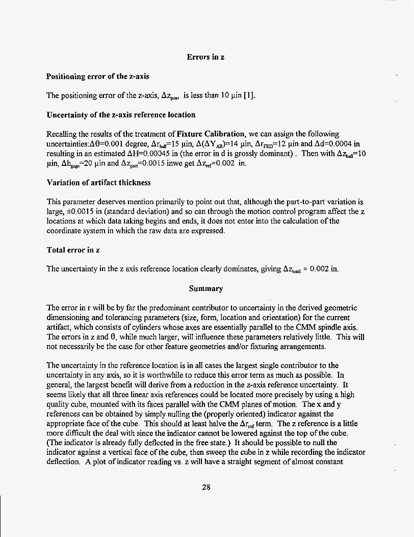
Errors in z
Positioning error of the z-axis
The positioning error of the z-axis,, A%, is less than 10 pin [ 13.
Uncertainty of the z-axis reference location
Recalling the results of the treatment of Fixture Calibration, we can assign the following uncertainties:A0=0.001 degree, Arb,=15 pin, A(AY,)=14 pin, Ar,,=12 pin and Ad=0.0004 in resulting in an estimated AH=0.00045 in (the error in d is grossly dominant) ~ Then with A%,=lO pin, Ahe=20 pin and A5,=0.00'15 inwe get Aqe,=0.002 in.
Variation of artifact thickness
This parameter deserves mention primarily to point out that, although the part-to-part variation is large, *0.0015 in (standard deviation) and so can through the motion control program affect the z locations at which data taking begins and ends, it does not enter into the calculation of the coordinate system in which the raw data are expressed.
Total error in z
The uncertainty in the z axis reference location clearly dominates, giving = 0.002 in.
Summary
The error in r will be by far the predominant contributor to uncertainty in the derived geometric dimensioning and tolerancing parameters (size, form, location and orientation) for the current artifact, which consists of cylinders whose axes are essentially parallel to the CMM spindle axis. The errors in z and 0, while much larger, will influence these parameters relatively little. This will not necessarily be the case for other feature geometries and/or fixturing arrangements.
The uncertainty in the reference location is in all cases the largest single contributor to the uncertainty in any axis, so it is worthwhile to reduce this error term as much as possible. In general, the largest benefit will derive from a reduction in the z-axis reference uncertainty. It seems likely that all three linear axis references could be located more precisely by using a high quality cube, mounted with its faces parallel with the CMM planes of motion. The x and y references can be obtained by simply nulling the (properly oriented) indicator against the appropriate face of the cube. This should at least halve the Armf term. The z reference is a little more difficult the deal with since the indicator cannot be lowered against the top of the cube. (The indicator is already hlly deflected in the free state.) It should be possible to null the indicator against a vertical face of the cube, then sweep the cube in z while recording the indicator deflection. A plot of indicator reading vs. z will have a straight segment of almost constant
28

deflection and a curved segment corresponding to contact of the probe ball with the edge of the cube. These segments can be extrapolated to a repeatable reference location. The achievable precision is uncertain but is certainly closer to tens of pin than to the current figure of 0.002 in.
29

Vm. REFERENCES
[ 13 R. D. Pilkey and P. A. Klevgard, Advanced Coordinate Measuring Machine at Sandia National Laboratories/California, SAND93 -8208, 1 993,3 2pp.
[2] K. D. Summerhays, R. P. Henke, R. M. Cassou, J. M. Baldwin and C. W. Brown, 1995, New Algorithms for the Evaluation of Discrete Point Measurement Data and for Sample Point SeZection on Surfaces wifh Systematic Form Deviation, Proceedings of the 10th Annual Meeting of the American Society for Precision Engineering, Austin, TX, 388-391 e
[3] J. M. Baldwin, R. P. Henke, K. D. Summerhays, R. M. Cassou and C. W. Brown, 1996, Optimizing Discrete Point Sample Patterns and Measurement Data Analysis on Internal Cylindrical Surfaces with Systematic Form Deviations, Proceedings of the International Manufacturing Engineering Conference, Storrs, CT, 447-449.
[4] R. P. Henke, R. M. Cassou, K. D. Summerhays, J. M. Baldwin, and C. W. Brown, 1996, Methodologies for the Evaluation of Systematic Form Deviations for Inside-Diameter Cyliridrical Features and Their Relationship to Process Variables, 1 1 th Annual Meeting of the American Society for Precision Engineering, Monterey, CA, accepted for presentation.
[5 ] anon., 1983, Series 8200 CNC Programming Mama1 for Mill Applications, Publication 8200-5.2.3, Allen-Bradley Co., Highland Heights, Ohio.
[6] M. Majlak, personal communication, September 1995.
30

Appendix A: Data Acquisition Program
31

The following program, written in the HT BASIC language and running on a 386 PC under DOS was used to control the data acquisition. The program handshakes with the Allen Bradley motion control program via interrupts on the COMl port. As shown in the Allen Bradley programs described in Appendix B, a control line on this port is toggled via coolant odof f commands which, in turn, drive a solid state relay. The listing is heavily commented and should be self- explanatory.
10 OPTIONBASE 1 ! Filename: DITSB 20 REALA 30 DIM Filename$[40],Part~num$[8],Hole~str$[40],Hole$( 10)[8] 40 50 COM @Gpib,@Zygo,@Voltimeter,REAL, Tzr(38,500,2) 60 Init-hpib ! Initialize the IEEE488 bus 70 Init-zygo ! Initialize the laser interferometer electronics 8 0 Initvol t met er 90 Init-coml ! Initialize the serial port 100 Num holes=O 110 LW%T "Enter Hole Numbers Separated By Commas:",Hole-str$
120 Get - holes(Ho1e-str$,Hole$( *),Num-holes)
130 Newqass: INPUT "Enter Part Number:",Part-num$
140 FOR Hole=l TO Num-holes 1 50 Filename$="d:\dit s\bw"&Hole$(Hole)&Part-num$&"_.000"
160 OUTPUT CRT;Filename$ ! Display it 170 CREATE Filename$, 1 ! Create a DOS ASCII file 180 ASSIGN @F TO Filename$ 190 FOR Counter=l TO 38 200 FOR Sample=l TO SIZE(Tzr,2) 210 Tzr(Counter,Sample, 1)=0. 220 NEXT Sample 230 NEXT Counter 240 Counter=-1 250 REPEAT 260 IF (Counter<O) THEN 270 Counter=O 280 STATUS 9,113 290 ENABLE INTR 9;s 3 00 310L: GOTOL 320 L10: GOSUB Read-xyz
INTEGER CounterJ, Sample, Sampsize(3 S),Num-holes,Hole
! Initialize the digital voltmeter
! Get a list of hole numbers to be measured
! Parse the list
! Serial number of the current part
! Build a filename based on hole & part numbers
! Open a path to it ! Initialize z values to zero in the data array
ON INTR 9 GOT0 L10
! So we know this is the start of data on this feature
! If the beginning of data acquisition on this feature ! This won't happen again ! Read modem status to clear interrupt ! Interrupt if modem status changes ! Set branch destination for coml interrupt ! Loop & wait ! Read x,y,z
32

330 ELSE 340 REPEAT 350 OFF INTR 9 3 60 Counter=Counter+ 1 3 70 STATUS 9,ll;I
3 80 ENABLE INTR 9;s 3 90 400 L1: GOTO L1 410 L l l : GOSUB Read-zr 420 UNTIL (Counte~38) 440 ENDIF 450 UNTIL (Counte~38) 460 Store-data(@F,Tzr( *), Sampsize( *)) 470 ASSIGN @F TO * 480 NEXTHole 490 GOTO Newqass
ON INTR 9,15 GOTO L11
! These are the data acquisition passes ! We will do this 38 times ! Disable interrupt branch ! Increment the scan counter ! Read the modem status register; need to do this ! here to ensure we won't get stale data ! Interrupt if modem status changes ! Set brandh destination for coml interrupt ! Loop & wait ! Read z & r ! Test the loop counter
Write the data file for this hole Close the file Repeat for all the holes on this part Go back, get data for next part
500 Read-xyz: STATUS 9,l l;I 510 Read_3d(X,Y,Z) ! Get the xyz location 520 OUTPUT @F USING "2(K,X),K";X,Y,Z
530 STATUS 9,l l;I ! Read the modem status register
! Read the modem status register to clear interrupt
! Write it to the file
Set the branch destination Re-enable coml interrupt
540 ON INTR 9,15 GOTO R1 550 ENABLE INTR 9;8 560 L2:! 570 GOTOL2 590 OFFINTR9 600 RETURN
610 Read zr: STATUS 9,l l;I 620 Samile=O 630 ON INTR 9 GOTO R2 640 ENABLE INTR 9;8 650 L3: 660 SEND 7;UNL LISTEN 23,24
Loop & wait Disable the interrupt branch
Read the modem status register Holds the number of samples in this pass Set the branch destination Enable the coml interrupt Loop reading z and r Unlisten all devices, make laser & voltmeter listeners
670 TRIGGER7 ! Trigger all listeners 680 DISABLE ! Disable interrupts while reading 690 OUTPUT @Zygo;"D 1 ",END ! Latch the laser reading 700 ENTER @Zygo USING "-K";S$ ! Read the laser output 710 ENABLE ! Reenable the interrupt 720 A=NUM( S $[ 1 ; 1 ])+(25 6. *NUM( S$[ 2; 1]))+(65 53 6. *NUM( S $[ 3; 1 I))
33
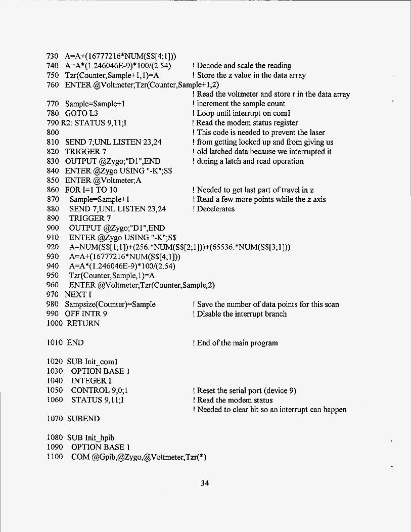
730 A=A+( 1677721 6*NUM(S$[4; 11)) 740 A=A*( 1.246046E-9)* 100/(2.54) ! Decode and scale the reading 750 Tzr(Counter,Sample+l, l)=A 760 ENTER @Voltmeter;Tzr(Counter,Sample+l,2)
770 Sample=Sample+l ! increment the sample count 780 GOTOL3 ! Loop until interrupt on coml 790 R2: STATUS 9, l l ;I ! Read the modem status register 800 ! This code is needed to prevent the laser 810 SEND 7;UNL LISTEN 23,24 ! from getting locked up and from giving us 820 TRIGGER7 ! old latched data because we interrupted it 830 OUTPUT @Zygo;"D 1 ",END ! during a latch and read operation
850 ENTER @Voltmeter;A 860 FORI=l TO 10 8 70 Sample=Sample+ 1 880 SEND 7;UNL LISTEN 23,24 890 TRIGGER7 900 OUTPUT @Zygo;"D 1 ",END
920 93 0
950 Tzr(Counter,Sample, 1)=A 960 ENTER @Voltmeter;Tzr(Counter,Sample,2) 970 NEXT1 9 8 0 S ampsize(Count er)=S ample 990 OFFINTR9 ! Disable the interrupt branch 1000 RETURN
! Store the z value in the data array
! Read the voltmeter and store r in the data array
840 ENTER @ZygO USING "-K";S$
910 ENTER @zygO USING "-K";S$ A=NUM( S$[ 1; 1])+(256. *NUM( S$[2; 1]))+(65536. *NUM( S$[3; 13)) A=A+( 1 67772 16*NUM( S $[4; 11))
940 A=A*( 1.246046E-9)* 100/(2.54)
! Save the number of data points for this scan
! Needed to get last part of travel in z ! Read a few more points while the z axis ! Decelerates
1010 END
1020 SUB Init-coml 1030 OPTION BASE 1 1040 INTEGER1 1050 CONTROL 9,O;l 1060 STATUS 9,l l;I
! End of the main program
1070 SUBEND
1080 SUB Init hpib
1 100 COM @Gpib,@Zygo,@Vsltmeter,Tzr(*) io90 OPTION BASE 1
34
! Reset the serial port (device 9) ! Read the modem status ! Needed to clear bit so an interrupt can happen

11 10 ASSIGN @Gpib TO 7 1120 ABORT 7 1130 RESET7
1140 CONTROL 7,O;l 1150 SUBEND
! Open a path to the IEEE488 bus ! Abort any operations in progress ! Reset to power up status; assert IFC, clear ! interrupts, set interface to be active controller ! Reset; DEC sent to IEEE488 card
1 160 SUB Init-voltmeter 1170 OPTION BASE 1 1 180 COM @Gpib,@Zygo,@Voltmeter,Tzr(*) 1190 ASSIGN @Voltmeter TO 724 1200 OUTPUT @Voltmeter;"RZ" ! Set the resolution 1210 SUBEND
! Open a path to the voltmeter
1220 SUB Initzygo 1230 1240 1250 1260 1270 1280
1290
1300 1310 1320 1330 1340 1350 1360 1370 1380 1390 1400 1410
OPTIONBASE 1 COM @Gpib,@Zygo,@Voltmeter,Tzr(*) REALA DIM Axes_status(3), Axesv(3), S $[4] ASSIGN @Gpib TO 7 ASSIGN @Zygo TO 723
! Open a path to the IEEE488 bus ! Open a path to the laser electronics (device 23)
ASSIGN @Volt to 724; FORMAT OFF
RESET 723 CLEAR 723 CONTROL 7,O;l OUTPUT @Z yg 0; CHR$(3) WAIT 1 OUTPUT @Zygo;"gl" WAIT 1 OUTPUT @Zygo;"d4" WAIT 1 OUTPUT @Zygo;"t3" WAIT 1 FOR 1=1 TO 2
! Open a path to the 3437A voltmeter (device 24) ! Reset the laser to powerup state ! Send SDC to the laser ! Reset IEEE488 control register ! Send <CTRL-C> to initialize laser
! Set latch only mode
!Binary mode output for laser
!Send EO1 on last character
1420 B: SEND 7 ; W LISTEN 23,24
1430 TRIGGER7 ! Trigger all listeners 1440 OUTPUT @Zygo;"D 1 ",END ! Latch the laser reading 1450 ENTER @Zygo USING "-K";S$ ! Read the laser output 1460 1470
! Unlisten all devices, make laser & voltmeter ! listeners
A=NUM( S $ [ 1 ; 1])+(25 6. *NUM( S $[2; 1]))+(65 53 6. *NUM( S$ [ 3; 11)) A=A+( 167772 16*NUM( S$[4; 13))
35

1520 1530 1540 1550 1560 1570 1580 1590 1600 1610 1620 1630 1640 1650 1660 1670 1680 1690 1700 1710 1720 1730
1480 A=A*(1.246046E-9)* lOW(2.54) ! Decode and scale the reading 1490 NEXT1 1500 SUBEND
1510 SUB Read-3d(REAL X,Y,Z) ! Reads a single xyz location COM @Gpib, @Zygo,@Volt meter,Tzr( *) DIM S$[4] REALA SEND 7;UNL LISTEN 23 TRIGGER 7 OUTPUT @Zygo;"Dl",END
GOSUB Calc Z=A SEND 7;UNL LISTEN 23 TRIGGER 7 OUTPUT @Zygo;"D2",END ENTER @ZygO USING "-K";S$ GOSUB Calc Y=-A SEND 7;UNL LISTEN 23 TRIGGER 7 OUTPUT @Zygo;"D3",END
GOSUB Calc X=A SUBEXIT
ENTER @ZygO USING "-K";S$
ENTER @ZygO USING "-K";S$
! Unlisten all devices, make laser a listener ! Trigger the laser ! Latch the laser z reading ! Read the laser output ! Decode and scale the reading ! Saveit ! Unlisten all devices, make laser a listener ! Trigger the laser ! Latch the laser y reading ! Read the laser output ! Decode and scale the reading ! Save it - Y axis is inverted ! Unlisten all devices, make laser a listener ! Trigger the laser ! Latch the laser x reading ! Read the laser output ! Decode and scale the reading ! Saveit
1810 Calc: ! 1820 A=NUM(S$[l;l J)+(256.*NUM(S$[2;]1]))+(65536.*NUM(S$[3;1])) 1830 A=A+( 16777216. *NuM(S$[4;1]))
1850 RETURN 1860 SUBEND
1840 A=A*(1.246046E-9)* 100/(2.54)
1870 SUB Store-data(@F,REAL Tzr(*),INTEGER Sampsize(*)) ! This subprogram computes the angle values, ! writes theta, z, r records to the data file
1880 OPTION BASE 1 1890 DIM Ang$[l8] 1900 INTEGER I, J, S 1910 REALTheta 1920 Theta=O. 1930 Inc=.027*360.
36

1940 Theta=+Inc 1950 J=O 1960 FOR 1=1 TO 37 1970 J=l 1980 S=Sampsize(I) 1990 Theta=Theta-Inc 2000 Ang$=VAL$(Theta) 2010 FOR J=1 TO S 2020 2030 NEXT J 2040 NEXT1 2050 SUBEND
OUTPUT @F USING "2(K,X),K";Ang$,Tzr(I,J, l),Tzr(I, J,2)
2060 SUB Get-holes(Ho1e-str$,Holes$( *),INTEGER Num-holes) ! This subprogram takes a comma-delimited string of hole numbers, returns a string array ! of the individual hole numbers and the hole count
2070 OPTIONBASE 1 2080 INTEGER I, J 2090 DIM H$[40] 2 100 H$=Hole-str$ 2110 I=O 2 120 WHILE (LEN(H$)>O) 2130 I=I+1 2140 J=POS(H$,",") 2 150 IF (J=O) THEN 2 160 Holes$(I)=H$ 2170 H$="" 2180 ELSE 2190 Holes$(I)=H$[ 1,J-lJ 2200 H$=H$[J+l] 2210 ENDIF 2220 ENDWHILE 2230 Num-holes=I 2240 SUBEND
While it is possible to enter motion control programs through the Allen Bradley control panel, it is more efficient to create them with a text editor and upload them through the serial port of the controller. The following listing, also in HT BASIC, provides a simple means to perform the upload.
10 OPTIONBASE 1
20 INTEGER1
! Program to upload motion control to the ! Allen Bradley serial port
37

30 DIM A$[512],F$[50] 40 ASSIGN @C TO 9 50 INPUT "ENTER PathV;ilename",F$ 60 ASSIGN @F TO F$ 70 CONTROL 9,O;l 80 CONTROL 9,3;9600 90 CONTROL 9,4;2 100 CONTROL 9, lOO; l 110 ON ERROR GOT0 L 130 FOR 1=1 TO 2 140 ENTER @F USING "K";A$ 150 OUTPUT CRT;A$
170 WAIT4 180 NEXT I 190 LOOP 200 ENTER @F USING "K";A$ 210 OUTPUT CRT;A$
230 WAIT .6 240 ENDLOOP 250 L: OUTPUT @C;CHR$(4) 260 ASSIGN @F TO * 270 END
160 OUTPUT @C USING "-,K";A$
220 OUTPUT @C USING "-,K";A$
! Open the serial port ! Get the filename & path to upload ! Open the file ! Reset the serial port ! 9600 baud
! Enable X O M O F F ! Detects EOF ! Read & send until EOF
! Close the file
38

Appendix B: Typical Motion Control Programs
39

Following are listings of SCANMAIN, a typical measurement control main program for the Allen Bradley controller, and of POSINCYL, and SCANCYL, the two macro programs that are called by any version of SCANMAIN to do the actual data acquisition. The listings show the program, in the Allen Bradley control language [ 5 ] , and explanatory comments, which are delimited by /* . . . */.
SCANMAIN
SCANMAIN is the main motion control program. It positions the CMM relative to the artifact, then repetitively calls subprograms POSNCYL to position the probe in relation to each feature and SCANCYL to scan the surface of the feature.
(AP,PH=2.82741 5,PD=. 1,PS=.2)
(AP,P4=SYP5=80)
M09
(CM,SCANCYL,PA=. 5 100)
G04F,P5 G90 co M07 G04F,P4
% /*rewind stop character*/ (AP,PU=22.482824,PV=l 0.05785;OyPQ=-. 1) /*assign parameters, PU=machine X location
of index hole, PV= machine Y location of index hole, PQ=offset in X so probe will clear wall of nominal hole (see notes)*/ /*assign parameters, PH=machine Z location of top surface of part, PD=Z distance to move in hole below surface of part when entering hole, PS=Z clearance for traversing moves above part*/ /*assign parameters, P4=delay time, PS=time to wait to write scan to disk, seconds*/ /*coolant OR used to toggle coml interrupt, end data taking*/ /*absolute programming, move end points relative to CAR zero position, inch mode*/ /*move C axis to 0 position*/ /*mist coolant on; used to toggle coml interrupt; start data taking*/
G90G70
co M07
G04FYP4 /*dwell P4 seconds*/ M09 /*coolant off*/ (CM,POSINCYL,PX=Z,PY= l.7,PU=PUyPV=PV,PQ=PQ,PH=PH,PD=PD,PS=PS) /*call macro
to position probe in hole to be scanned, PX=X location of hole, PY=Y location of hole relative to index hole*/ /*call macro to scan hole, PA= Z length of scan (see notes)*/ /*dwell P5 seconds to store data*/ /*absolute programming*/ /*move C axis to 0 position*/ /*mist coolant on*/ /*dwell P4 seconds*/
40

M09 /*coolant o P l (CM,POSINCYL,PX= 1. 7,PY=2,PU=PU,PV=PV,PQ=PQyPH=PHyPD=PD,PS=PS) /*call macro
(CM,SCANCYL,PA=. 5 100) G04FYP5 /*dwell P5 seconds*/ G90 /*absolute programming*/ co M07 /*mist coolant on*/ G04F,P4 /*dwell P4 seconds*/ M09 /*coolant o P / (CM,POSINCYL,PX=2,PY=2.3,PU=PU,PV=PVyPQ=PQ,PH=PH,PD=PD,PS=PS) /*call macro
(CM,SCmTCYL,,PA=.5 100) G04F,P5 /*dwell P5 seconds*/ G90 /*absolute programming*/ co M07 /*mist coolant on*/ G04FYP4 /*dwell P4 seconds*/ M09 /*coolant OF/ (CM,POSINCYL,PX=2.3 ,PY=2,PU=PU,PV=PV,PQ=PQ,PH=PH7PD=PD,PS=PS) /*call macro
(CM,SCANCYL,PA=S 100) G04F,P5 /*dwell P5 seconds*/ G90 /*absolute programming */ co G01Z7 M3 0
to position for second hole*/ /*call macro to scan second hole*/
/*move C axis to 0 position*/
to position for third hole*/ /*call macro to scan third hole*/
/*move C axis to 0 position*/
to position for fourth hole*/ /*call macro to scan fourth hole*/
/*move C axis to 0 position*/ /*retract quill to Z=7 inches*/ /*end of program, rewind tape*/
Notes:
1) Example main motion control program for data acquisition on four features.
2 ) This assumes quill axis will be positioned on feature axis and indicator is set up for proper size hole.
3) Z length of scan is computed as follows: a. For a through hole, PA=nominal depth + 0.01 inch. b. For a blind hole, PA=nominal depth - (ball radius + tolerance on depth + 0.01 inch)
4) Dwell length, in seconds, to store data is P5=130 * hole depth in inches.
5 ) See reference 5 for details of Allen Bradley programming language.
41

POSINCYL
This subprogram is called by SCA-, once per feature, and positions the CMM relative to the feature.
YO @M,PO SINCYL) GO 1 Z,(PH+P S)
GO lX,(PU+PX+PQ)
GO 1 Y,(PV+PY)
GOlX,(PU+PX) GOlZ,(PH-PD)
/*rewind stop character*/ /*define macro named POSINCYL*/ /*move in Z, linear interpolation, to top of part(PH) + clearance(PS)*/ /*move in X to index hole location + feature location + offset to keep probe from surface of hole*/ /*move in Y to hole location + feature location*/ /*move in 2, PD into hole from top of part*/ /*move in X, to position probe against surface of hole*/ /*move in 2, to position probe center in top plane of part*/ /*end macro*/
/*rewind*/
SCANCYL
This subprogram is called by SCANhUIN, once per feature, and scans the feature.
% @M, SCANCYL) (AP,P2=0,P3=19,P4=.5)
G90
L1 M07 GOlZ,-PA MO9 G04F,P4
G04F7P4 M07 GO 1 Z,PA
C-.02700
/*rewind stop character*/ /*define macro to scan a full cylinder*/ /*assign parameters, P2=scan counter, initialized to 0, P3= number of bidirectional scans to be made, P4=dwell time*/ /*incremental programming, move destinations are relative to current location*/ /*L-word for if-then destination*/ /*mist coolant on, toggle coml interrupt to start taking data*/ /*linear interpolation, move in Z to scan depth*/ /*coolant off, toggle coml interrupt to stop taking data*/ /*dwell P4 seconds*/ /*rotate C axis 0.027 revolution*/ /*dwell P4 seconds*/ /*mist coolant on*/ /*scan in 2 back to top ofpart*/
42

I
M09 /*coolant OF/ G04F,P4 /*dwell P4 seconds*/ C-.02700 (AP,P2=P2+1) /*increment P2*/ (IFT,P2,LT,P3,L 1) (EM) /*end macro*/
T /*rewind*/
/*rotate C axis 0.027 revolution*/
/*if P2<P3 goto L1 and scan again*/
(EM)
-t
43

Appendix C: Machine Drawing of Cylinder Artifact
44

A p p l i e r t o Holes 3-46
2x [R.zso+
8.0( R E F
30.000' 7 2X @ 0.315 +/- 0.005
# . O O S @ A
U # 0.500 +/- 0.005 TO T SHOWN ON BOTH S I D E S I"
I8 0 0
17
a
2 0 o7 -J=G
IS
1 4 0 0 1 6
13
0 0
1 1 0 0 12 0 0
e-- 6.000 REF -
3.500
~
tx "e-mq
Figure 12. Cylinder artifact; top view.
45

SEE DET
A l l Around Ootsldt and 2x Three Pocket Areas p q - ~nI.OIOIKIs@~ 3 X 9 0.375 +/- 0.010
1#.OlO@ IKlS@ 1 0.500 +/- 0.020
2x [ = I -1
. LSEE DETAIL c M 1.900
Figure 113. Cylinder artifact; bottom view.
46

Figure 14. Cylinder artifact; side view.
P
SECT 1 ON POCKET DEPTHS-POCKET DEPTHS
Figure 15. Cylinder artifact; section view.
47

I= ___! 2.7 so )---
--I
48

3x
2x I
- 0
DETAIL B SCALE 0.750
Figure 17. Cylinder artifact; detail B.
49

DETAIL C SCALE 0.750
Figure 18. Cylinder artifact; detail C.
50
I - s
c

HoIe #*
1
1A
1B
2
2A
2B
3
4
5
6
7
8
9
10
11
12
13
14
15
16
17
18
19
Table C-1. List of Full Cylindrical Features on the Artifact.
X Dim.
0.000
0.000
0.000
0.000
0.000
0.000
-2.000
-2.000
-1.750
-2.250
-2.250
-2.000
-2.000
1.400
1.400
1.900
2.000
1.700
2.000
2.3 00
-2.300
-2.300
-1.700
Y Dim.
-3.500
-3.500
-3.500
3.500
3.500
3.500
-3.250
-2.750
-3 .OOO
-3 .OOO
-1.500
-1.250
-1.750
-3.250
-2.750
-2.750
-1.800
-1.500
- 1.200
-1.500
-0.300
0.300
0.300
Dia. k0.005
0.375
0.500
0.500
0.375
0.500
0.500
0.0625
0.0625
0.0625
0.0625
0.125
0.125
0.125
0.125
0.125
0.125
0.250
0.250
0.250
0.250
0.250
0.250
0.250
Full Dia. Depth *0.020
0.500
0.250
0.250
0.500
0.250
0.250
0.250
0.250
0.1875
0.1875
0.375
0.375
0.375
0.500
0.500
0.500
0.500
0.500
0.500
0.500
0,750
0.750
0.750
BIind/ Through/ Counter
T
C
C
T
C
C
T
T
B
B
B
B
B
T
T
T
T
T
T
T
B
B
B
Mfg. Process* *
C/D
C / D M
C / D M
C/D
C/DM
C / D M
C/D
C/D/R
C / D
CfDR
C/D
C/D/R
C/DiB/R
C/D
C D / R
C/D/B/R
C/D
C/DR
C/D/B/R
C/D/P
C/D
C/D/R
C/DiB/R
51

Table C-l(cont). List of Full Cylindrical Features on the Artifact.
Hole #*
20
21
22
23
24
25
26
27
28
29
30
31
32
33
34
35
36
37
38
39
40
41
42
X Dim.
-1.700
-2.400
-2.000
-1.600
-2.000
1.700
1.700
2.300
2.300
1.600
2.000
2.400
2.000
-2.000
-2.000
-1.400
- 1.400
2.350
1.650
2.350
1.650
0.625
-0.625
Y Dim.
-0.300
1.500
1 .goo
1.500
1 .zoo -0.300
0.300
0.300
-0.300
1.500
1.900
1.500
1.100
2.750
3.250
3.250
2.750
3.350
3.350
2.650
2.650
0.500
0.500
Dia. k0.005
0.250
0.3 125
0.3 125
0.3 125
0.3 125
0.375
0.375
0.375
0.375
0.3 125
0.3 125
0.3 125
0.3 125
0.375
0.375
0.375
0.375
0.500
0.500
0.500
0.500
0,500
0.500
Full Dia. Depth *0.020
0.750
0.700
0.700
0.700
0.700
1 .ooo 1 .ooo 1 .ooo 1 .ooo 0.750
0.750
0.750
0.750
0.700
0.700
0.700
0.700
1 .ooo 1 .ooo 1 .ooo 1.000
0.650
0.650
Blind/ Through/ Counter
B
B
B
B
B
T
T
T
T
T
T
T
T
B
B
B
B
T
T
T
T
B
B
Mfg. Process* *
CiDiP
C/D
C / D R
C/DiBiR
C/D/P
C/D
C/D/R
CiD/B/R
C/D/P
C/D
C/D/R
C/DiB/R
C/DP
C/D
C/D/R
C/D/B/R
C/D/P
C / D
C D / R
C/DiB/R
C/DP
C/D
C / D R
52

Table C-l(cont). List of Full Cylindrical Features on the Artifact.
Hole #* X Dim.
43 -0.625
44 0.625
45 0.000
46 0.000
Y Dim.
-0.500
-0.500
-2.250
2.000
Dia. k0.005
0.500
0.500
1 .ooo 1 .ooo
Full Dia. Depth k0.020
0.650
0.650
1 .ooo 1 .ooo
Blind/ Through/ Counter
B
B
T
T *Refer to hole numbers on drawing. * *C=center drill, D=drill, R=ream, B=bore, P=plunge end mill, M=mill
~~
Mfg. Process" *
C/D/B/R
C/DD
C/D
C / D R
53

UNLIMITED RELEASE
INITIAL DISTRIBUTION
Ronald M. Cassou Harney Science Center University of San Francisco 2130 Fulton Street San Francisco, California 94 1 17- 1080
Kim D. Summerhays Harney Science Center, Room 409 University of San Francisco 2130 Fulton Street San Francisco, California 941 17-1080 (3)
Richard P. Henke MicroVu 7909 Conde Lane Windsor, California 95492
C. W. Brown Allied Signal FM&T 2000 E. 95th St. PO BOX 419159,D/458,2B27 Kansas City, Missouri 64 14 1-3 548
MS900 1 T. 0. Hunter, 8000 Attn: MS9005 J. B. Wright, 2200
MS9004 M. E. John, 8100 MS9054 W. J. McLean, 8300 MS9007 R. C. Wayne, 8400 MS9002 P. N. Smith, 8500 MS9405 T. M. Dyer, 8700 MS9141 P. Brewer, 8800 MS9003 D. L. Crawford, 8900
MS9133 MS9133 K. A. Hontz, 8220 MS9133 MS9420 L. A. West, 8200
J. M. Baldwin, 8220 (20)
R. D. Pilkey, 8220 (10)
Attn: MS9430 L. N. Tallerico, 8204 MS9404 B. E. Af€eldt, 8210 MS9405 M. H. Rogers, 8220 MS9405 J. M. Hruby, 8230
I 54

MS943 0 MS9133 J. A. Fordham, 8240-1 MS9409 R. H. Stulen, 8250 MS9 107 V. C. Barr, 8250-1
A. J. West, 8240
MS9405 Manager, 8220 MS0953 W.E. Alzheimer, 1500 MS0665 L. J. Azevedo, 1541
MS9021 MS902 1 MS0899 Technical Library (4) MS90 18
Technical Communications Department, 8535, for OSTI (10) Technical Communications Department, 853 5/Technical Library, MS0899, 134 14
Central Technical Files, 8523-2 (3)
4
55/56