Embed Size (px)
Citation preview
C19_007 1
Modified Brayton Refrigeration Cycles for Liquid Hydrogen in Spallation Neutron Source Moderator
H.-M. Chang1,2, S.G. Kim1, J.G. Weisend II2, H. Quack3
1 Hong Ik University, Seoul, 121-791, Korea 2 European Spallation Source, SE-221 00 Lund, Sweden3 TU Dresden, D-01062 Dresden, Germany
ABSTRACT
to cool liquid hydrogen in spallation neutron facilities. The target moderators under development at ESS require a refrigeration capacity of 30 kW at 20 K to remove the dissipated energy from
examined for improved
on existing and proposed designs, eight different cycles are selected and analyzed fully with the FOM
as an index of the thermodynamic performance, and the detailed exergy expenditure is also investi-
refrigeration at 20 K.
INTRODUCTIONCryogenic refrigeration at 20 K is required for liquid-hydrogen moderators in spallation neu-ryogenic refrigeration at 20 K is required for liquid-hydrogen moderators in spallation neu-at 20 K is required for liquid-hydrogen moderators in spallation neu-
tron source facilities1-5. As shown in Figure 1, the dissipated energy of neutrons is removed at the
2loop of liquid hydrogen can be plotted as a counterclockwise triangular cycle on the phase diagram,
according to the magnitude of the pressure drop and the temperature rise, which are restored by a pump and by the refrigerator, respectively. In order to avoid any vaporization, liquid hydrogen
completion1-3. A much larger cryogenic moderator system has been recently designed and will be 4,5, where the maximum heat load is
estimated to be over 30 kW during the operation with a full level of beam power.
463Cryocoolers 19, edited by S.D. Miller and R.G. Ross, Jr.©¶International Cryocooler Conference, Inc., Boulder, CO, 2016
C19_007 2
1-3. Helium is the only possible gas refrigerant for this application, as a cryogenic
other design requirements. The thermodynamic design of the 30 kW refrigerator for ESS is a new and exciting challenge at 20 K, since it requires not only the largest capacity ever, but also a set of thermo-hydraulic and geometric constraints5. This study investigates the structures of standard or
large-scale refrigerators at 20 K.
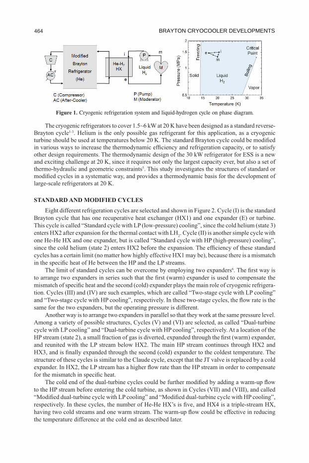
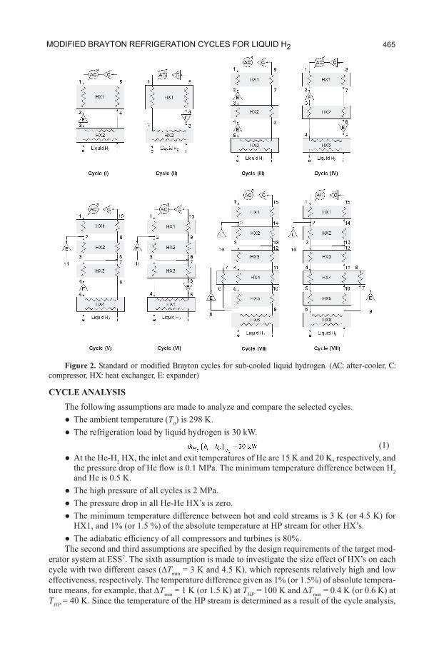
STANDARD AND MODIFIED CYCLES
2
The limit of standard cycles can be overcome by employing two expanders6
-
same for the two expanders, but the operating pressure is different.Another way is to arrange two expanders in parallel so that they work at the same pressure level.
structure of these cycles is similar to the Claude cycle, except that the JT valve is replaced by a cold
the temperature difference at the cold end as described later.
Figure 1. Cryogenic refrigeration system and liquid-hydrogen cycle on phase diagram.
BRAYTON CRYOCOOLER DEVELOPMENTS 464
C19_007 3
CYCLE ANALYSISThe following assumptions are made to analyze and compare the selected cycles.
T0
2 he inlet and exit temperatures of He are 15 K and 20 K, respectively, and 2
and He is 0.5 K. The
The minimum temperature difference between hot and cold streams is.
compressors and-
erator system at ESS7
Tmin-
ture means, for example, that Tmin THP = 100 K and TminTHP
Figure 2. Standard or modified Brayton cycles for sub-cooled liquid hydrogen. (AC: after-cooler, C: compressor, HX: heat exchanger, E: expander)
MODIFIED BRAYTON REFRIGERATION CYCLES FOR LIQUID H2 465
C19_007 4this assumption will be imposed by a few iterative calculations. In calculating the input power to the compressors, a single-stage compression is assumed, because the pressure ratio is between 3
two-stage compression with inter-cooling is assumed for the pressure ratios exceeding 10.®
number of given equations by one. The cycle analysis is repeated over one variable, until the input power can be minimized under the assumptions.
The thermodynamic performance of a refrigeration cycle is evaluated with a dimensionless index, FOM , which is
The minimum work is the thermodynamic limit for a reversible cycle, which can be expressed
where h and s . The subscripts e and i denote the exit and inlet of He-H2 , as shown in Figure 1 and 2, and T0 is the ambient temperature at which heat is rejected by the refrigerator. WEmay be used to drive the compressors or may be simply dissipated, but the input WC - WEis counted in 2
For a better understanding of the thermodynamic nature of cycles, analysis is presented as well. Combining the energy and entropy balance equations9, the exergy balance can be written as:
4
where the left-handed side is the exergy input for refrigeration, and the right-handed side shows . FOM,
and the remaining terms are the irreversibility or the entropy generation rate multiplied by ambient temperature. The total irreversibility can be itemized for the components in the system, including
. In case of Cycles through III , the mixing of two streams is another source of entropy generation, but is not
included here, since the magnitude is negligibly small for an optimized cycle10.
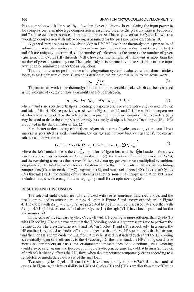
RESULTS AND DISCUSSIONThe selected eight cycles are fully analyzed with the assumptions described above, and the
results are plotted as temperature-entropy diagram in Figure 3 and exergy expenditure in Figure 4. The cycles with Tmin
Tminmaximum FOM.
2
2scheduled or unscheduled decrease of thermal load.
FOM’s than the standard
BRAYTON CRYOCOOLER DEVELOPMENTS 466
C19_007 5
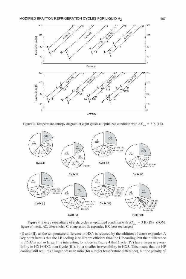
in FOM -
Figure 3. Temperature-entropy diagram of eight cycles at optimized condition with Tmin = 3 K (1%).
Figure 4. Exergy expenditure of eight cycles at optimized condition with Tmin = 3 K (1%). (FOM: figure of merit, AC: after-cooler, C: compressor, E: expander, HX: heat exchanger)
MODIFIED BRAYTON REFRIGERATION CYCLES FOR LIQUID H2 467
C19_007 6
FOM’s than the two-stage -
. The optimal condition is determined such that the exit tempera-
the FOMFOM
FOM
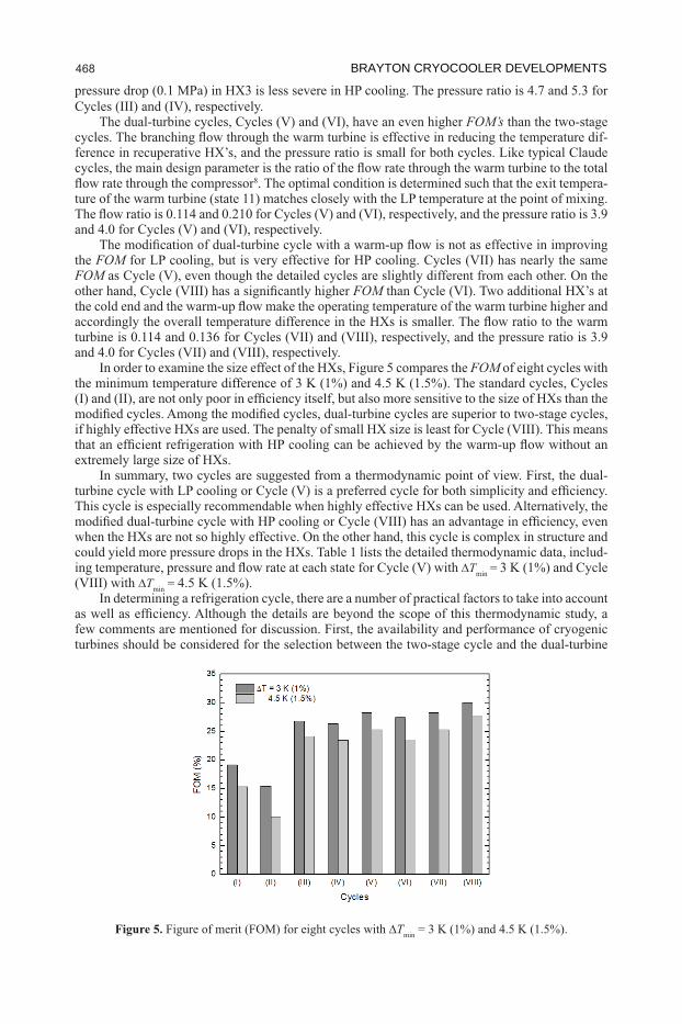
FOM of eight cycles with
can be achieved
In summary, two cycles are suggested from a thermodynamic point of view. First, the dual-
-Tmin =
Tmin = In determining a refrigeration cycle, there are a number of practical factors to take into account
few comments are mentioned for discussion. First, the availability and performance of cryogenic turbines should be considered for the selection between the two-stage cycle and the dual-turbine
Figure 5. Tmin
BRAYTON CRYOCOOLER DEVELOPMENTS 468

C19_007 7
In dual-turbine cycles, on the contrary, the warm turbine requires a large pressure ratio with a small
-
Finally, an optimization theory is
problem subject to a constraint, which has been solved by the method of Lagrange multiplier. The results show that the best thermodynamic performance is achieved when the temperature difference is proportional to the absolute temperature9,11.
5
This condition has been already incorporated as an assumption of the cycle analysis.
CONCLUSIONS
terms of FOM
expander in a cycle, and the two-stage or dual-turbine cycles, depending on the combination of the two expanders. Among the eight cycles under consideration, two cycles are suggested along with
to the neutron source moderators at ESS, and should be useful in large-scale refrigeration at 20 K as well.
ACKNOWLEDGMENTThis work was partially supported by 2016 Hong Ik University Research Fund for sabbatical
leave in a foreign institute.
Table 1.
MODIFIED BRAYTON REFRIGERATION CYCLES FOR LIQUID H2 469

C19_007 REFERENCES
1.
Adv. in Cryogenic Engineering
2. Adv. in Cryogenic
Engineering
3. Adv. in Cryogenic Engineering,
4. IOP Conference Series: Materials Science and Engineering ,
5. IOP Conference Series: Materials Science and
Engineering
6. , pp. 435-442.
7. European Spallation Source, pp. 41-42.
Cryogenic systems
9. Advanced Engineering Thermodynamicspp. 101-142.
10. Cryogenics
11. Cryogenics
BRAYTON CRYOCOOLER DEVELOPMENTS 470