Embed Size (px)
Citation preview
Modified Version of High Efficiency Dehumidification System (HEDS) ESTCP Presentation EW-201344
Hosted by:
FEDERAL UTILITY PARTNERSHIP WORKING GROUP SEMINAR
November 3-4, 2015Houston, TX
Original Presentation by:Dahtzen Chu
U.S. Army Construction Engineering Research LaboratoryScot Duncan, PE, Retrofit Originality, Inc.
Omar Chamma, Trane
What We’ll Discuss
• This presentation will discuss several different methods that are currently utilized for Relative Humidity (RH) control in DoD facilities and some of their comparative strengths and weaknesses.
• The main focus of the discussion will be on the “High Efficiency Dehumidification System” or “HEDS” that is in the process of undergoing testing thru the ESTCP process.
• The appendices contain FAQ’s and Psychrometric charts for typical reheat and recuperative designs.
Federal Utility Partnership Working Group November 3-4, 2015 Houston, TX
Comparative Baselines at DoD and Nationally
Baseline for the demonstrated technology comes in several variations.
1. Simplest and most widespread comparative baseline system consists of an AHU with a chilled water or DX refrigerant sourced cooling coil that cools the air down to between 52F and 55F.
1. Removes moisture from the air via condensation, then utilizes a heating coil, either sourced by hot water or an electric reheat coil to raise the supply air temperature to lower the Relative Humidity of the air entering the spaces, drying the spaces out.
2. AHU’s equipped with Run Around coils for reheat duty in various configurations:
1. Upstream of main Cooling Coil (CC) to downstream of main CC,
2. Exhaust air to Supply air, (does not reduce plant energy in this configuration)
3. Heat pipe coils configured as above,
4. Air to Air heat exchangers as configured above.
3. Other comparative dehumidification systems consist of variations of high pressure AHU’s equipped with some form of desiccant wheel that absorbs moisture from the supply air without requiring cooling to dry the air out via condensation of moisture. Recuperative energy requirements can be high.
Federal Utility Partnership Working Group November 3-4, 2015 Houston, TX
Comparative Baselines at DoD and Nationally
Baseline in most DoD buildings/installations for the demonstrated technology comes in several variations.
1. The simplest and by far the most widespread comparative baseline system consists of an AHU with a chilled water or DX refrigerant sourced cooling coil that cools the air down to between 52F and 55F to remove moisture from the air via condensation, then utilizes a heating coil, either sourced by hot water or an electric reheat coil to raise the supply air temperature to lower the Relative Humidity of the air entering the spaces, drying the spaces out.
a. Due to the high cooling, heating and electrical energy consumption of these designs and the fact that many installations shut their heating systems off during the summer, the reheat portion of the dehumidification process is typically shut down.
b. This allows 100% water saturated, 100% Relative Humidity, very cold supply air to enter the occupied spaces. When this cold, water saturated air comes in contact with solids in a space, condensation can occur. Wherever there is condensation, there is the high likelihood of unwanted biological growth occurring, which will later require substantial expense to remediate.
Federal Utility Partnership Working Group November 3-4, 2015 Houston, TX
Comparative Baselines at DoD and Nationally (cont.)
2. Other comparative dehumidification systems consist of variations of high pressure AHU’s equipped with some form of desiccant wheel that absorbs moisture from the supply air without requiring cooling to dry the air out via condensation of moisture.
The relatively new desiccant wheel based Dedicated Outdoor Air System (DOAS) system usually requires a substantial amount of ductwork, over and above that required for a HEDS unit, as the exhaust air, plus a substantial amount of added heat, are used to dry out the chemicals in the desiccant wheel so that the process can begin anew.
The relative downsides of these desiccant wheel based systems may include a very high construction cost, higher operational costs, higher energy use, specialized and higher maintenance requirements that are typically not available in facility maintenance budgets, and maintenance manpower skills that are not typical at the installations.
Federal Utility Partnership Working Group November 3-4, 2015 Houston, TX
Industry “State of the Art” is 100 Years Old
Typically installed dehumidification system in DoD facilities consists of an AHU equipped with a cooling coil sized to cool air down to condense moisture out of the air, then a reheat coil, using a new heating energy source of either heated water or an electric heater, to warm the air back up and lower the Relative Humidity.
Some newer designs take this same concept and package it into a “Dedicated Outdoor Air System” or “DOAS”.
Still others of relatively recent design use a desiccant wheel based system to dry the air out.
Simplicity Advances the State of the ArtThe HEDS design was born out of the global need for a simple to operate, simple to maintain, simple to understand, energy efficient, cost effective, sustainable way to reduce biological growth and promote occupant health, comfort and productivity.
At energy efficiency projects for a multitude of installations in a variety of climates, we found mold present in a widespread manner. The facility maintenance and operations staffs were all aware of the situation, they were all concerned about the mold growth and they were doing what they could to kill the worst case growths, but when the HVAC system is working against them continually, they were never able to win the battle, let alone win the war, against biological growth.
The usual culprits were poorly designed HVAC systems that were never designed for relative humidity control, the lack of heat to perform reheat duties to lower the RH of the supply air, and failed DOAS units due to complexity and lack of maintenance funds and skill sets.
Faced with the status quo of rampant mold growth in many facilities, the challenge was to develop a dehumidification system that did not need new, added energy for reheat and that could be maintained by an operator with the skill sets to maintain a normal chilled water based AHU.
Federal Utility Partnership Working Group November 3-4, 2015 Houston, TX
Attribution
Many figures and substantial information for the older dehumidification technologies are excerpted from or based on several articles written by Donald P. Gatley, P.E. President, Gatleyand Associates for HPAC Engineering Magazine in 2000. For more details on the older technologies, Mr. Gatleys’ articles are available on-line.
Federal Utility Partnership Working Group November 3-4, 2015 Houston, TX
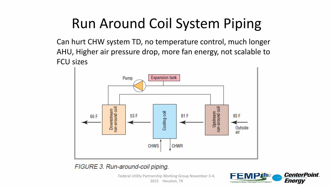
Run Around Coil System PipingCan hurt CHW system TD, no temperature control, much longer AHU, Higher air pressure drop, more fan energy, not scalable to FCU sizes
Federal Utility Partnership Working Group November 3-4, 2015 Houston, TX
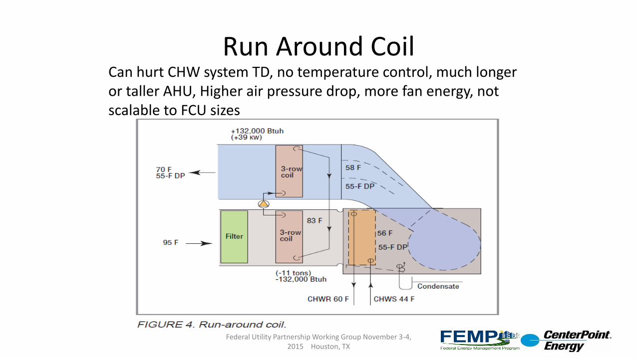
Run Around CoilCan hurt CHW system TD, no temperature control, much longer or taller AHU, Higher air pressure drop, more fan energy, not scalable to FCU sizes
Federal Utility Partnership Working Group November 3-4, 2015 Houston, TX
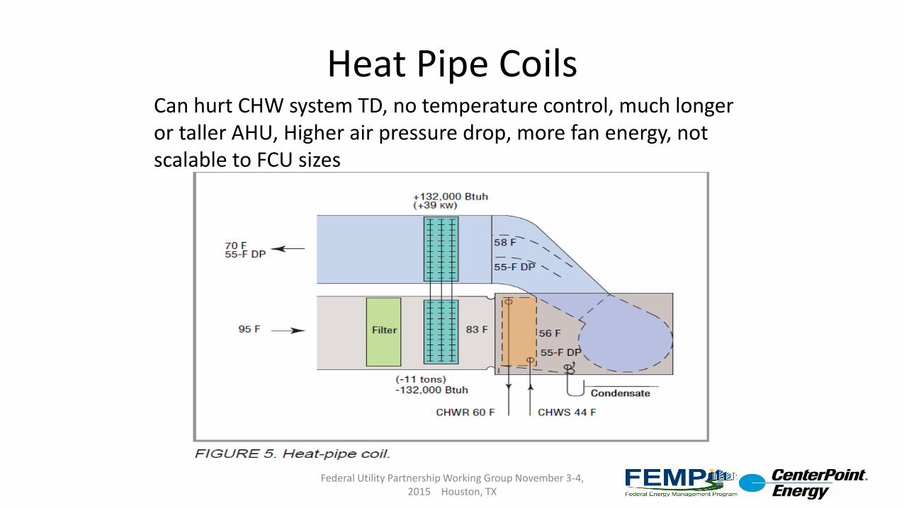
Heat Pipe CoilsCan hurt CHW system TD, no temperature control, much longer or taller AHU, Higher air pressure drop, more fan energy, not scalable to FCU sizes
Federal Utility Partnership Working Group November 3-4, 2015 Houston, TX
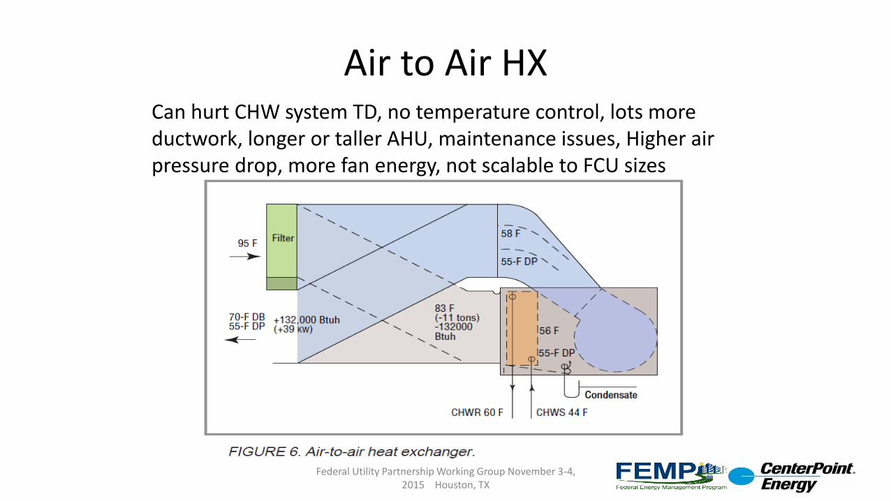
Air to Air HXCan hurt CHW system TD, no temperature control, lots more ductwork, longer or taller AHU, maintenance issues, Higher air pressure drop, more fan energy, not scalable to FCU sizes
Federal Utility Partnership Working Group November 3-4, 2015 Houston, TX
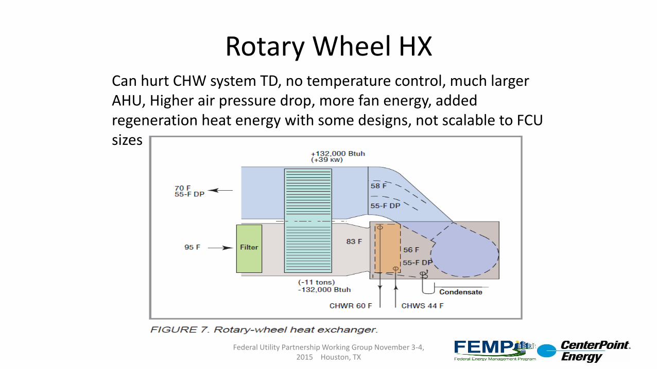
Rotary Wheel HXCan hurt CHW system TD, no temperature control, much larger AHU, Higher air pressure drop, more fan energy, added regeneration heat energy with some designs, not scalable to FCU sizes
Federal Utility Partnership Working Group November 3-4, 2015 Houston, TX

HEDS Comparison to “Normal” Dehumidification/ Reheat AHU
Federal Utility Partnership Working Group November 3-4, 2015 Houston, TX
Traditional AHU Designed for Dehumidification Duty. Small cooling and reheat coils, high CHW flow rates, low CHW temperature differential and high AHU air pressure drops. 45°F CHW enters the cooling coil (5A) at 70 GPM and leaves the cooling coil at 55°F. A new source of 140°F water enters the reheat coil (6A) at 4 GPM and leaves the reheat coil at 87°F. The unit requires 479,319 BTU’s per hour to cool, dehumidify and reheat 10,000 CFM of air at the design conditions in this example
Data Points 1 thru 4: [1] 10,000 CFM airflow [2] 78°F dry bulb temp, 65°F wet bulb temp [3] 55°F dry bulb, 55°F dewpoint, essentially 100% relative humidity [4] 65.3°F dry bulb, 55°F dewpoint, 55% RH
High Efficiency Dehumidification System (HEDS) AHU (53% Peak Day BTUH Savings) Very large cooling and cooling recovery coils, low CHW flow rates, high CHW temperature differential and low AHU air pressure drops. 45°F CHW enters the cooling coil (5) at 27 GPM and leaves the cooling coil at 70°F. This 70°F water then enters the CRC coil (6) at 27 GPM and leaves the CRC coil at 62°F while heating the air to 65°F. The HEDS unit requires 226,187 BTU’s per hour to cool, dehumidify and reheat 10,000 CFM of air at the same conditions, a BTUH savings of 53% and a CHW flow reduction of 62% in this example.
Blue=Cold Temperatures, Yellow to Red = Warm to Hot Temperatures.
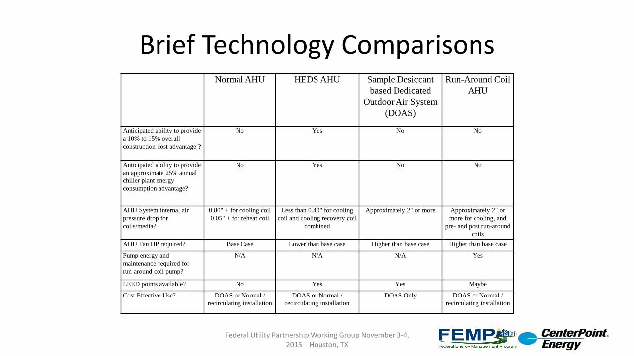
Brief Technology Comparisons
Federal Utility Partnership Working Group November 3-4, 2015 Houston, TX
Normal AHU HEDS AHU Sample Desiccant
based Dedicated
Outdoor Air System
(DOAS)
Run-Around Coil
AHU
Anticipated ability to provide
a 10% to 15% overall
construction cost advantage ?
No Yes No No
Anticipated ability to provide
an approximate 25% annual
chiller plant energy
consumption advantage?
No Yes No No
AHU System internal air
pressure drop for
coils/media?
0.80" + for cooling coil
0.05" + for reheat coil
Less than 0.40" for cooling
coil and cooling recovery coil
combined
Approximately 2" or more Approximately 2" or
more for cooling, and
pre- and post run-around
coils
AHU Fan HP required? Base Case Lower than base case Higher than base case Higher than base case
Pump energy and
maintenance required for
run-around coil pump?
N/A N/A N/A Yes
LEED points available? No Yes Yes Maybe
Cost Effective Use? DOAS or Normal /
recirculating installation
DOAS or Normal /
recirculating installation
DOAS Only DOAS or Normal /
recirculating installation
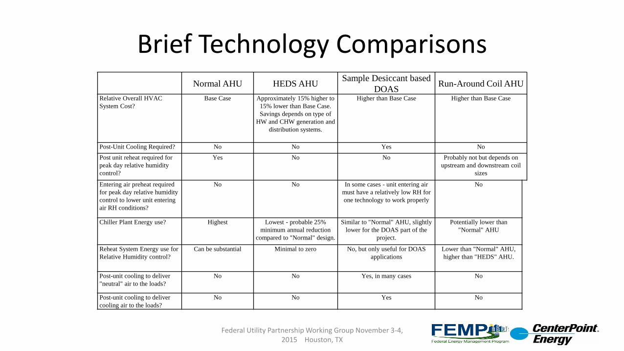
Brief Technology Comparisons
Federal Utility Partnership Working Group November 3-4, 2015 Houston, TX
Normal AHU HEDS AHUSample Desiccant based
DOASRun-Around Coil AHU
Relative Overall HVAC
System Cost?
Base Case Approximately 15% higher to
15% lower than Base Case.
Savings depends on type of
HW and CHW generation and
distribution systems.
Higher than Base Case Higher than Base Case
Post-Unit Cooling Required? No No Yes No
Post unit reheat required for
peak day relative humidity
control?
Yes No No Probably not but depends on
upstream and downstream coil
sizes
Entering air preheat required
for peak day relative humidity
control to lower unit entering
air RH conditions?
No No In some cases - unit entering air
must have a relatively low RH for
one technology to work properly
No
Chiller Plant Energy use? Highest Lowest - probable 25%
minimum annual reduction
compared to "Normal" design.
Similar to "Normal" AHU, slightly
lower for the DOAS part of the
project.
Potentially lower than
"Normal" AHU
Reheat System Energy use for
Relative Humidity control?
Can be substantial Minimal to zero No, but only useful for DOAS
applications
Lower than "Normal" AHU,
higher than "HEDS" AHU.
Post-unit cooling to deliver
"neutral" air to the loads?
No No Yes, in many cases No
Post-unit cooling to deliver
cooling air to the loads?
No No Yes No
Brief Technology Comparisons
Federal Utility Partnership Working Group November 3-4, 2015 Houston, TX
Normal AHU HEDS AHUSample Desiccant based
DOAS
Run-Around Coil
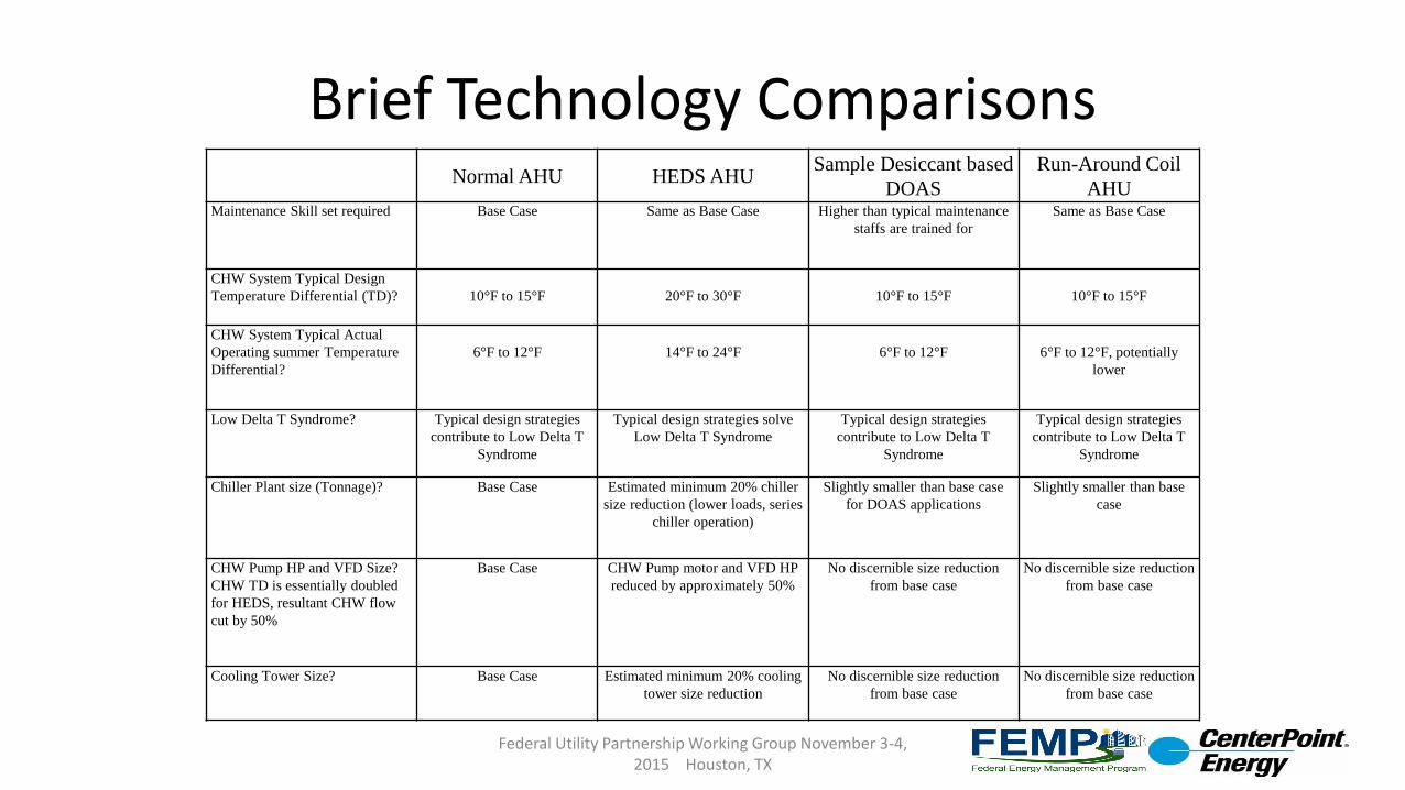
AHUMaintenance Skill set required Base Case Same as Base Case Higher than typical maintenance
staffs are trained for
Same as Base Case
CHW System Typical Design
Temperature Differential (TD)? 10°F to 15°F 20°F to 30°F 10°F to 15°F 10°F to 15°F
CHW System Typical Actual
Operating summer Temperature
Differential?
6°F to 12°F 14°F to 24°F 6°F to 12°F 6°F to 12°F, potentially
lower
Low Delta T Syndrome? Typical design strategies
contribute to Low Delta T
Syndrome
Typical design strategies solve
Low Delta T Syndrome
Typical design strategies
contribute to Low Delta T
Syndrome
Typical design strategies
contribute to Low Delta T
Syndrome
Chiller Plant size (Tonnage)? Base Case Estimated minimum 20% chiller
size reduction (lower loads, series
chiller operation)
Slightly smaller than base case
for DOAS applications
Slightly smaller than base
case
CHW Pump HP and VFD Size?
CHW TD is essentially doubled
for HEDS, resultant CHW flow
cut by 50%
Base Case CHW Pump motor and VFD HP
reduced by approximately 50%
No discernible size reduction
from base case
No discernible size reduction
from base case
Cooling Tower Size? Base Case Estimated minimum 20% cooling
tower size reduction
No discernible size reduction
from base case
No discernible size reduction
from base case
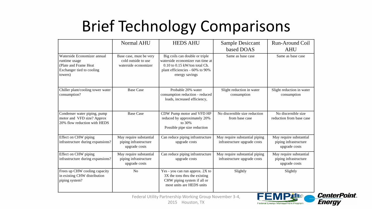
Brief Technology Comparisons
Federal Utility Partnership Working Group November 3-4, 2015 Houston, TX
Normal AHU HEDS AHU Sample Desiccant
based DOAS
Run-Around Coil
AHUWaterside Economizer annual
runtime usage
(Plate and Frame Heat
Exchanger tied to cooling
towers)
Base case, must be very
cold outside to use
waterside economizer
Big coils can double or triple
waterside economizer run time at
0.10 to 0.15 kW/ton total Ch.
plant efficiencies - 60% to 90%
energy savings
Same as base case Same as base case
Chiller plant/cooling tower water
consumption?
Base Case Probable 20% water
consumption reduction - reduced
loads, increased efficiency,
Slight reduction in water
consumption
Slight reduction in water
consumption
Condenser water piping, pump
motor and VFD size? Approx
20% flow reduction with HEDS
Base Case CDW Pump motor and VFD HP
reduced by approximately 20%
to 30%
Possible pipe size reduction
No discernible size reduction
from base case
No discernible size
reduction from base case
Effect on CHW piping
infrastructure during expansions?
May require substantial
piping infrastructure
upgrade costs
Can reduce piping infrastructure
upgrade costs
May require substantial piping
infrastructure upgrade costs
May require substantial
piping infrastructure
upgrade costs
Effect on CHW piping
infrastructure during expansions?
May require substantial
piping infrastructure
upgrade costs
Can reduce piping infrastructure
upgrade costs
May require substantial piping
infrastructure upgrade costs
May require substantial
piping infrastructure
upgrade costs
Frees up CHW cooling capacity
in existing CHW distribution
piping system?
No Yes - you can run approx. 2X to
3X the tons thru the existing
CHW piping system if all or
most units are HEDS units
Slightly Slightly
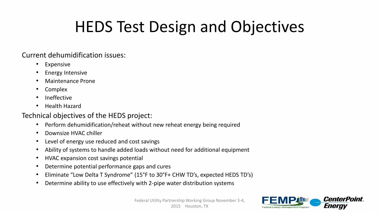
HEDS Test Design and Objectives
Current dehumidification issues:• Expensive
• Energy Intensive
• Maintenance Prone
• Complex
• Ineffective
• Health Hazard
Technical objectives of the HEDS project:• Perform dehumidification/reheat without new reheat energy being required
• Downsize HVAC chiller
• Level of energy use reduced and cost savings
• Ability of systems to handle added loads without need for additional equipment
• HVAC expansion cost savings potential
• Determine potential performance gaps and cures
• Eliminate “Low Delta T Syndrome” (15°F to 30°F+ CHW TD’s, expected HEDS TD’s)
• Determine ability to use effectively with 2-pipe water distribution systems
Federal Utility Partnership Working Group November 3-4, 2015 Houston, TX
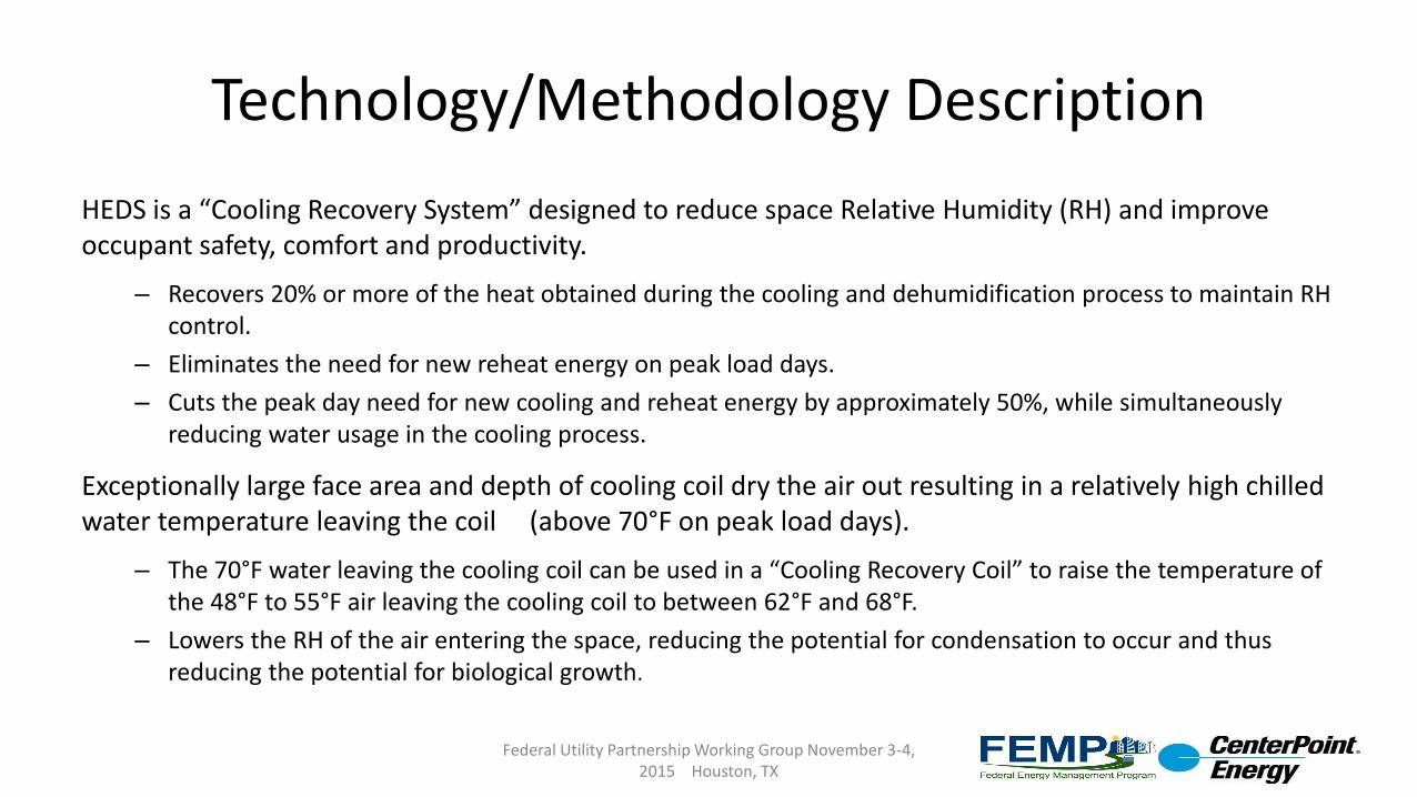
Technology/Methodology Description
HEDS is a “Cooling Recovery System” designed to reduce space Relative Humidity (RH) and improve occupant safety, comfort and productivity.
– Recovers 20% or more of the heat obtained during the cooling and dehumidification process to maintain RH control.
– Eliminates the need for new reheat energy on peak load days.
– Cuts the peak day need for new cooling and reheat energy by approximately 50%, while simultaneously reducing water usage in the cooling process.
Exceptionally large face area and depth of cooling coil dry the air out resulting in a relatively high chilled water temperature leaving the coil (above 70°F on peak load days).
– The 70°F water leaving the cooling coil can be used in a “Cooling Recovery Coil” to raise the temperature of the 48°F to 55°F air leaving the cooling coil to between 62°F and 68°F.
– Lowers the RH of the air entering the space, reducing the potential for condensation to occur and thus reducing the potential for biological growth.
Federal Utility Partnership Working Group November 3-4, 2015 Houston, TX
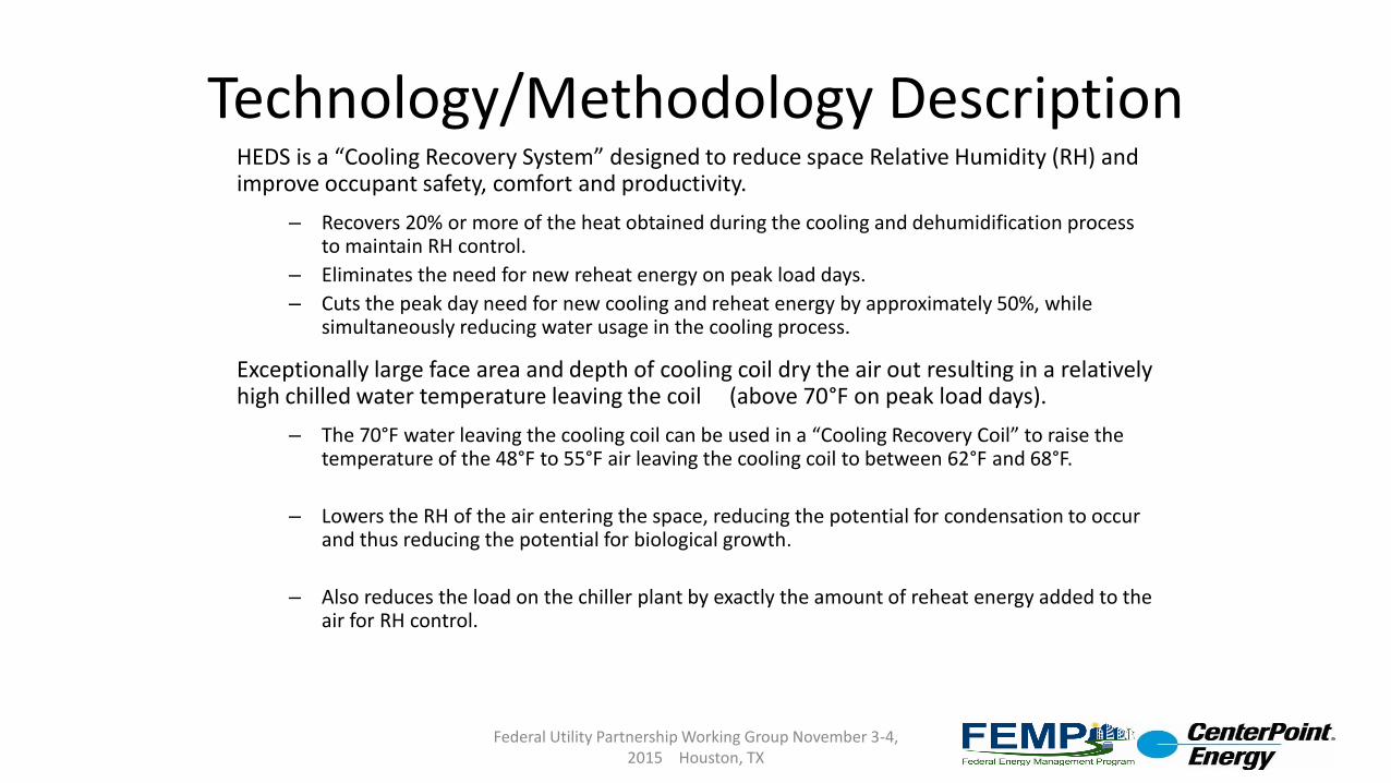
Technology/Methodology DescriptionHEDS is a “Cooling Recovery System” designed to reduce space Relative Humidity (RH) and improve occupant safety, comfort and productivity.
– Recovers 20% or more of the heat obtained during the cooling and dehumidification process to maintain RH control.
– Eliminates the need for new reheat energy on peak load days.
– Cuts the peak day need for new cooling and reheat energy by approximately 50%, while simultaneously reducing water usage in the cooling process.
Exceptionally large face area and depth of cooling coil dry the air out resulting in a relatively high chilled water temperature leaving the coil (above 70°F on peak load days).
– The 70°F water leaving the cooling coil can be used in a “Cooling Recovery Coil” to raise the temperature of the 48°F to 55°F air leaving the cooling coil to between 62°F and 68°F.
– Lowers the RH of the air entering the space, reducing the potential for condensation to occur and thus reducing the potential for biological growth.
– Also reduces the load on the chiller plant by exactly the amount of reheat energy added to the air for RH control.
Federal Utility Partnership Working Group November 3-4, 2015 Houston, TX
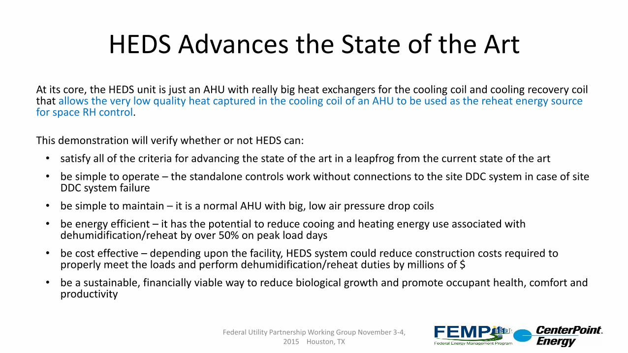
HEDS Advances the State of the Art
At its core, the HEDS unit is just an AHU with really big heat exchangers for the cooling coil and cooling recovery coil that allows the very low quality heat captured in the cooling coil of an AHU to be used as the reheat energy source for space RH control.
This demonstration will verify whether or not HEDS can:
• satisfy all of the criteria for advancing the state of the art in a leapfrog from the current state of the art
• be simple to operate – the standalone controls work without connections to the site DDC system in case of site DDC system failure
• be simple to maintain – it is a normal AHU with big, low air pressure drop coils
• be energy efficient – it has the potential to reduce cooing and heating energy use associated with dehumidification/reheat by over 50% on peak load days
• be cost effective – depending upon the facility, HEDS system could reduce construction costs required to properly meet the loads and perform dehumidification/reheat duties by millions of $
• be a sustainable, financially viable way to reduce biological growth and promote occupant health, comfort and productivity
Federal Utility Partnership Working Group November 3-4, 2015 Houston, TX
Technology Snapshot – Typical Base Case
Federal Utility Partnership Working Group November 3-4, 2015 Houston, TX
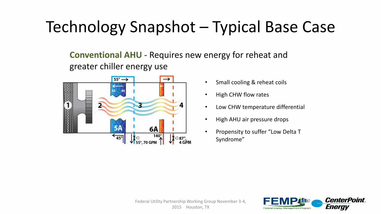
Conventional AHU - Requires new energy for reheat and greater chiller energy use
• Small cooling & reheat coils
• High CHW flow rates
• Low CHW temperature differential
• High AHU air pressure drops
• Propensity to suffer “Low Delta T Syndrome”
Technology Snapshot – HEDS Unit
Federal Utility Partnership Working Group November 3-4, 2015 Houston, TX
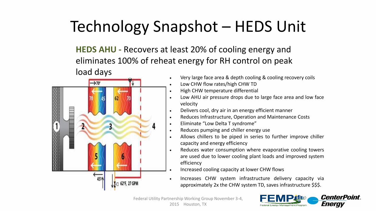
HEDS AHU - Recovers at least 20% of cooling energy and eliminates 100% of reheat energy for RH control on peak load days
Very large face area & depth cooling & cooling recovery coils Low CHW flow rates/high CHW TD High CHW temperature differential Low AHU air pressure drops due to large face area and low face
velocity Delivers cool, dry air in an energy efficient manner Reduces Infrastructure, Operation and Maintenance Costs Eliminate “Low Delta T syndrome” Reduces pumping and chiller energy use Allows chillers to be piped in series to further improve chiller
capacity and energy efficiency Reduces water consumption where evaporative cooling towers
are used due to lower cooling plant loads and improved systemefficiency
Increased cooling capacity at lower CHW flows
Increases CHW system infrastructure delivery capacity viaapproximately 2x the CHW system TD, saves infrastructure $$$.
Technology Lifecycle Cost Savings
The ESTCP process will help us determine the real world lifecycle savings potential of the HEDS AHU design.
1. Benefits of the HEDS design include
a. Very simple design process,
b. Simple installation process
c. Simple operation and maintenance requirements
2. Reduced First and Lifecycle Cost Potential
a. Ability to greatly extend the life of capacity constrained chilled water generation plants and chilled water distribution systems.
b. Potential to save millions of $$$ in reduced infrastructure costs for facilities that are adding loads to the cooling loop.
3. Renewable/HEDS Benefits
a. The energy efficiency benefits of a HEDS based system will allow renewable energy technologies to either be downsized, or be used to serve a greater overall percentage of an installations energy consumption.
Federal Utility Partnership Working Group November 3-4, 2015 Houston, TX
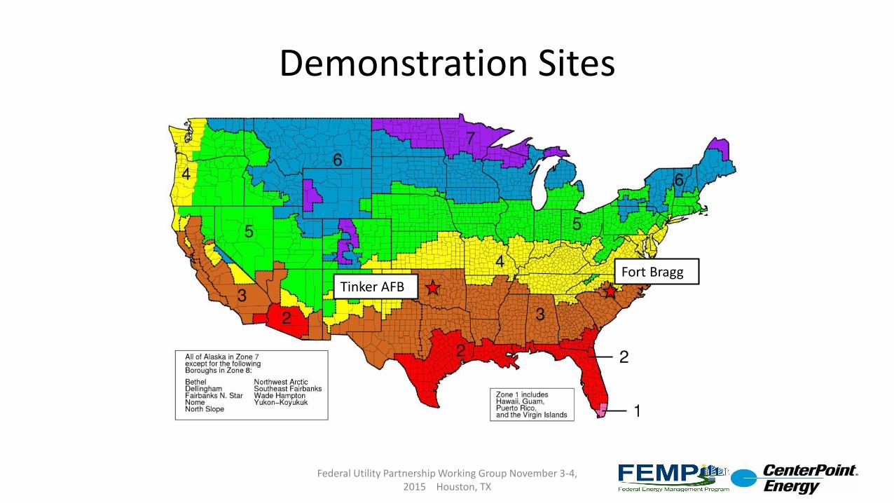
Demonstration Sites
Federal Utility Partnership Working Group November 3-4, 2015 Houston, TX
Tinker AFBFort Bragg
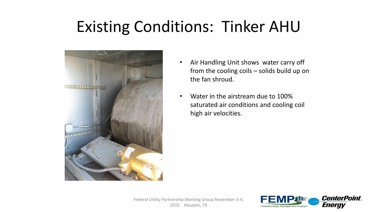
Existing Conditions: Tinker AHU
Federal Utility Partnership Working Group November 3-4, 2015 Houston, TX
• Air Handling Unit shows water carry off from the cooling coils – solids build up on the fan shroud.
• Water in the airstream due to 100% saturated air conditions and cooling coil high air velocities.

Tinker AFB Existing AHU on Rooftop
Federal Utility Partnership Working Group November 3-4, 2015 Houston, TX
HEDS AHU will fit on the same structural support system
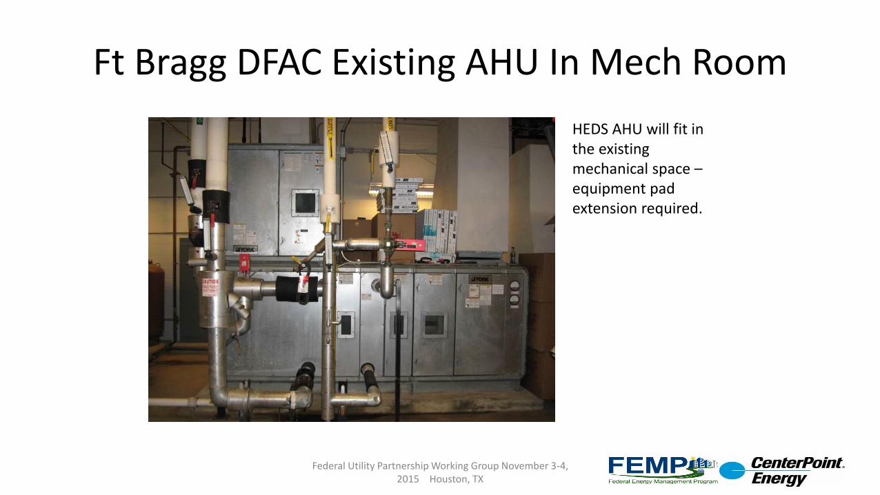
Ft Bragg DFAC Existing AHU In Mech Room
Federal Utility Partnership Working Group November 3-4, 2015 Houston, TX
HEDS AHU will fit in the existing mechanical space –equipment pad extension required.
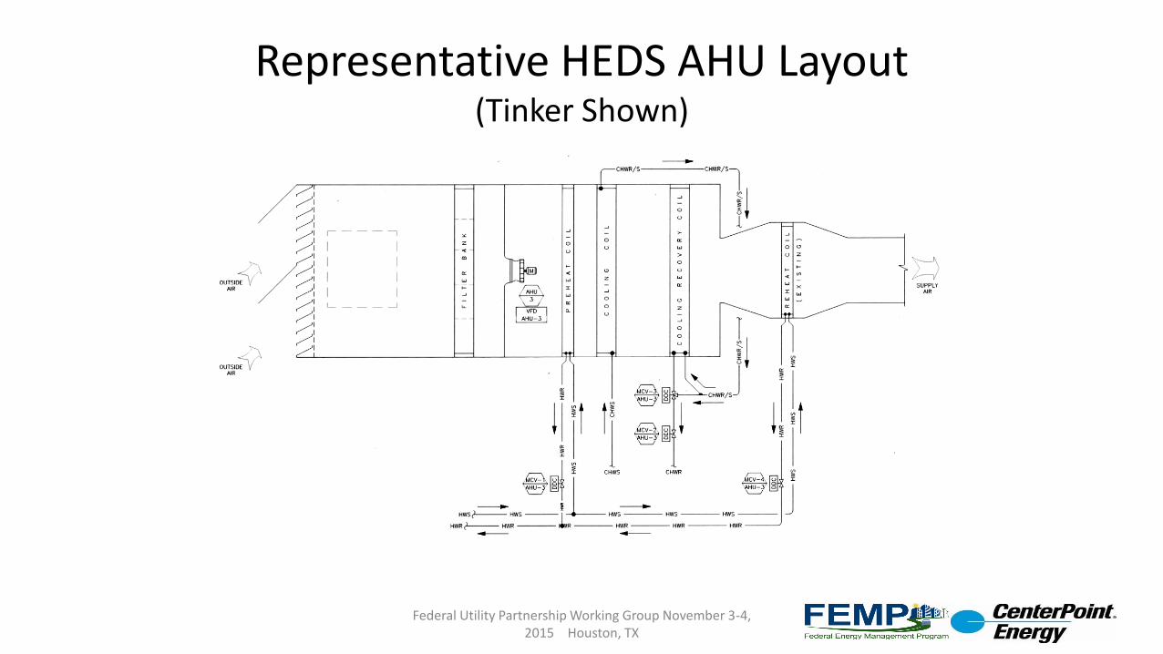
Representative HEDS AHU Layout (Tinker Shown)
Federal Utility Partnership Working Group November 3-4, 2015 Houston, TX
Expected Performance Improvements
Federal Utility Partnership Working Group November 3-4, 2015 Houston, TX
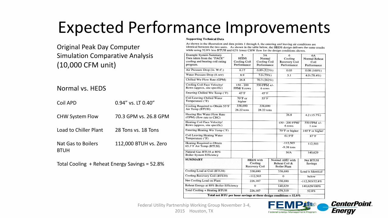
Original Peak Day Computer Simulation Comparative Analysis
(10,000 CFM unit)
Normal vs. HEDS
Coil APD 0.94” vs. LT 0.40”
CHW System Flow 70.3 GPM vs. 26.8 GPM
Load to Chiller Plant 28 Tons vs. 18 Tons
Nat Gas to Boilers 112,000 BTUH vs. Zero BTUH
Total Cooling + Reheat Energy Savings = 52.8%
Technology Implementation/Available Products
What should DoD consider when implementing the technology?
1. Although the HEDS testing has not proceeded yet, when designing an HVAC system for comfort conditioning, RH control or process loads (such as paint hangars), adequate physical space needs to be allocated for the HEDS units.
2. In very tight mechanical spaces, the HEDS unit will not be able to be located in that space, as they are physically larger than a “normal” AHU. HEDS units will typically be smaller than a desiccant wheel based system that delivers the same conditions.
What products are on the market or will emerge soon?
1. There are no products currently on the market that offer the benefits of the HEDS design.
2. It is possible to build HEDS AHU’s immediately, or to retrofit existing facilities that desire RH control for process, comfort or biological control with the HEDS design strategies.
3. We are hoping that the upcoming demonstration at Tinker AFB will demonstrate that the HEDS design can be a viable retrofit option to massively cut energy use for their 100% outside air paint hangars, which are the largest single energy users on the base when they are in operation. You can imagine the electrical and thermal demand of cooling and reheating 300,000 CFM of outside air in Oklahoma in the summer for one paint hangar.
Federal Utility Partnership Working Group November 3-4, 2015 Houston, TX
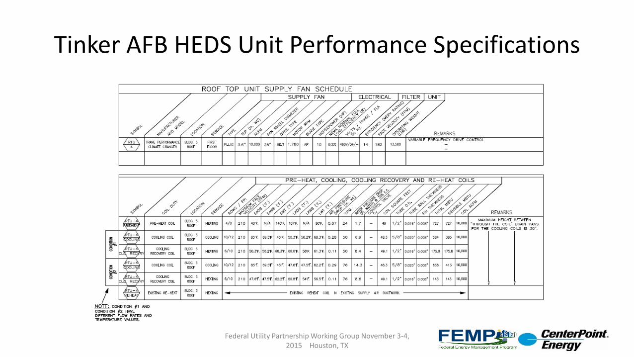
Tinker AFB HEDS Unit Performance Specifications
Federal Utility Partnership Working Group November 3-4, 2015 Houston, TX
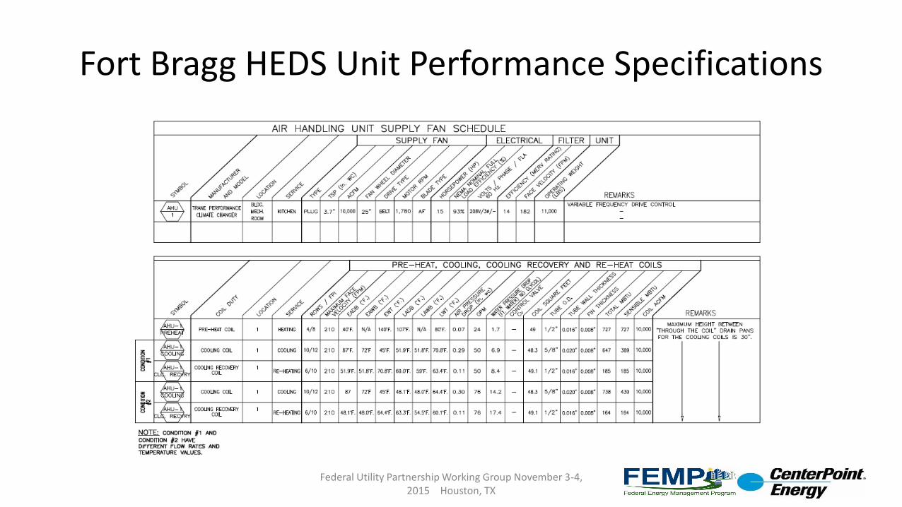
Fort Bragg HEDS Unit Performance Specifications
Federal Utility Partnership Working Group November 3-4, 2015 Houston, TX
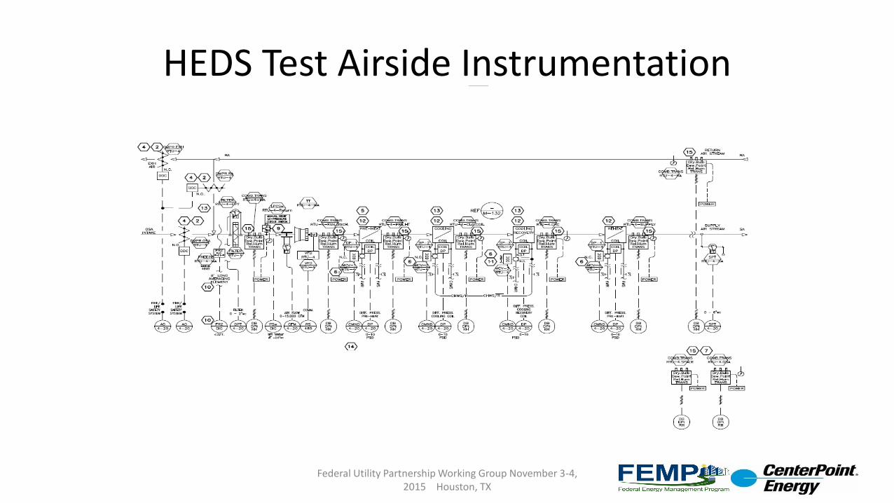
HEDS Test Airside Instrumentation
Federal Utility Partnership Working Group November 3-4, 2015 Houston, TX
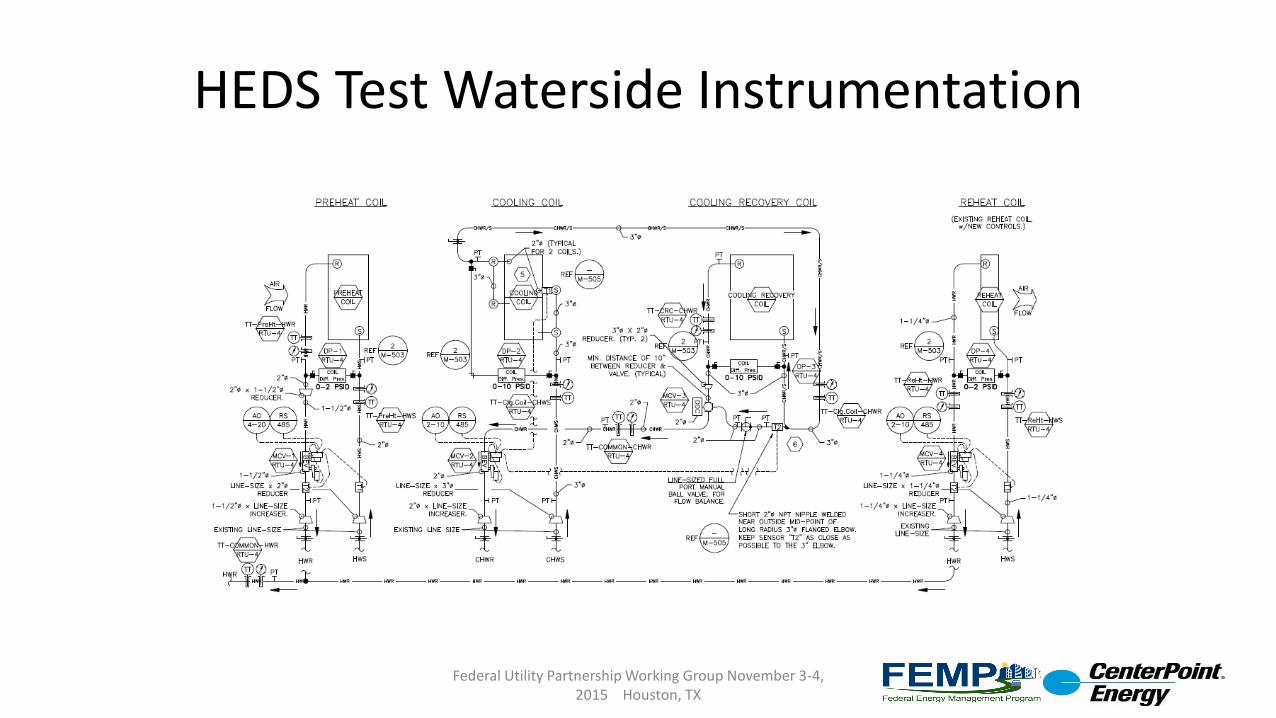
HEDS Test Waterside Instrumentation
Federal Utility Partnership Working Group November 3-4, 2015 Houston, TX
Section 1.5 Appendices, Supporting Technical Data & FAQs Cont.
Federal Utility Partnership Working Group November 3-4, 2015 Houston, TX
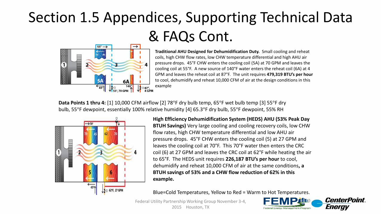
Traditional AHU Designed for Dehumidification Duty. Small cooling and reheat coils, high CHW flow rates, low CHW temperature differential and high AHU air pressure drops. 45°F CHW enters the cooling coil (5A) at 70 GPM and leaves the cooling coil at 55°F. A new source of 140°F water enters the reheat coil (6A) at 4 GPM and leaves the reheat coil at 87°F. The unit requires 479,319 BTU’s per hourto cool, dehumidify and reheat 10,000 CFM of air at the design conditions in this example
Data Points 1 thru 4: [1] 10,000 CFM airflow [2] 78°F dry bulb temp, 65°F wet bulb temp [3] 55°F dry bulb, 55°F dewpoint, essentially 100% relative humidity [4] 65.3°F dry bulb, 55°F dewpoint, 55% RH
High Efficiency Dehumidification System (HEDS) AHU (53% Peak Day BTUH Savings) Very large cooling and cooling recovery coils, low CHW flow rates, high CHW temperature differential and low AHU air pressure drops. 45°F CHW enters the cooling coil (5) at 27 GPM and leaves the cooling coil at 70°F. This 70°F water then enters the CRC coil (6) at 27 GPM and leaves the CRC coil at 62°F while heating the air to 65°F. The HEDS unit requires 226,187 BTU’s per hour to cool, dehumidify and reheat 10,000 CFM of air at the same conditions, a BTUH savings of 53% and a CHW flow reduction of 62% in this example.
Blue=Cold Temperatures, Yellow to Red = Warm to Hot Temperatures.
Frequently Asked Questions
FAQsOne of our team members started designing “Large Temperature Differential” (LTD) cooling systems in 1985, with initial systems designed to deliver 76°F chilled water return temps when the coils were provided with 39°F chilled water from a chilled water Thermal Energy Storage (TES) system. The LTD design reduced the TES tank size by 65% due to the very large CHW temperature differential. Most LTD coils provide 70°F to 74°F CHW return temps on design days, so there is enough low quality heat available for reclaim to be used as a reheat source for Relative Humidity control. 25 years of experience with large cooling coils delivering high CHW return temperatures contributed to the design of the HEDS.
Q: Is HEDS acceptable to be used in a retrofit, or only new installs? A: The biggest target market is the retrofit market, where the most problems exist and the most obvious benefits are to be had.
In a retrofit application, we are hoping that HEDS will solve the high RH/ mold/ mildew problems that exist, substantially cut energy and water waste, solve the “Low Delta T” problem, solve heating and cooling capacity problems, solve undersized infrastructure problems, reduce manpower and maintenance costs, and lower the overall lifecycle costs for DoD facilities.
If HEDS is designed into new construction or facility expansion projects, we are hoping that lower overall installation costs will occur, as well as lower overall lifecycle costs.
NOTE: the answers are based on studies and evaluations, the ESTCP project is needed to prove the performance and potential limitations in the real world.
Federal Utility Partnership Working Group November 3-4, 2015 Houston, TX
FAQ’s, Cont.
Q: Will HEDS really provide chiller plant downsizing? A: Yes, based on the evaluations completed so far. To reduce the possibility of condensation forming, the COE would like to deliver approximately 65°F dry bulb temperature air at 55°F dewpoint conditions, which results in a supply air RH of around 55%. On a sample barracks project of approximately 150 rooms, the cooling load to dehumidify the air to 55°F dewpoint, starting at 78°F dry bulb and 65°F wet bulb calculates out to approx. 147 tons. To raise the supply air temperature from 55°F to 65°F to obtain 55% RH air conditions, heat totaling 486,000 BTUH must be added. With a “normal” dehumidification/reheat design, 486,000 BTUH of heating hot water, or 142 kW of electric strip heaters would be required to warm up the air. With the HEDS unit, the “Cooling Recovery Coil” uses the chilled water that leaves the cooling coil at approximately 70°F as the source of heating water that is used to raise the air temp to 65°F. Simultaneously with the rise in air temperature, there is a corresponding drop in the chilled water return temperature in the CRC, equal to the same 486,000 BTUH that was transferred into the supply air. 486,000 BTUH equates to approximately 41 tons, so the net load on the chiller plant equates to approximately 147 tons cooling load, minus the 41 tons of cooling energy that was recovered in the reheat process, for a net chiller plant load of 106 tons. This should allow the chiller plant associated with a HEDS design to be reduced in capacity by approximately 25% to 30% while still meeting peak load days.
Federal Utility Partnership Working Group November 3-4, 2015 Houston, TX
FAQ’s, Cont.
Q: Can HEDS reduce Infrastructure Costs? A: Yes, based on the evaluations completed so far. A benefit of HEDS is that the chilled water flow rate required to meet peak day cooling/dehumidification needs will be reduced by approximately 50% to 60% by a combination of reduced cooling plant loads and increased chilled water system temperature differentials provided by the very large cooling coils.On sites that may be stretching the limits of their piping infrastructure, the ability to meet the same cooling loads with a 50% to 60% reduction in the flow rate can mean that the avoided costs from not having to replace the piping infrastructure can cover the most or all of the costs of HEDS retrofit projects. While not a HEDS project, one of our team members has been working with the University of Southern California since 1992, and has helped raise their CHW system temperature differential from 8°F to 9°F during peak summer months in 1992, up to 25°F to 27°F today. This has allowed USC to avoid replacing their underground piping, as the installed piping can now move 300% more BTU’s per gallon due to the higher chilled water temperature differential. This is a savings of over $15,000,000 for the campus.
Q: Can HEDS improve efficiencies of added facilities? A: Yes. When new facilities are being added, or facilities are being rehabilitated or expanded, the HEDS design can be incorporated to reduce lifecycle costs. If a chiller plant has reached the maximum capacity that it can deliver, the piping infrastructure may also be maxed out as described above. If the plant and piping system capacity is maxed out, there are two remedies – 1) add more chiller, cooling tower, pumping and piping capacity, and potentially an addition to the chiller plant building to house the new equipment, which can all add up to tens of millions of dollars just to add one more building, or 2) make better use of the installed equipment and piping by decreasing the cooling loads on the plant and increasing the system temperature differentials to decrease piping system congestion by using the HEDS design.
Federal Utility Partnership Working Group November 3-4, 2015 Houston, TX
FAQ’s, Cont.
Q: Can HEDS help to solve the “Low Delta T Syndrome”?
A: Yes. One of the key drivers for the Low Delta T Syndrome is undersized cooling coils. By nature of the HEDS design, the heat transfer surface area of the cooling coils is more than 300% greater than a typical 6 row, 10 fins per inch coil at the normal 550 feet per minute face velocity.
Q: Can HEDS handle added loads without additional equipment and reduce expensive upgrades? A: Yes. As described above, if HEDS is incorporated, it will free up additional capacity in the cooling plants and the chilled water distribution piping systems.
Q: Does HEDS require a 2-pipe system, or will it also work with a 4-pipe system? A: HEDS works with both system types. One of the beauties of the HEDS design is that it can provide cooled and dehumidified air with a 2-pipe system, without requiring electric reheat or complex and hard to maintain desiccant wheel based equipment. With a 2-pipe system in the winter, the hot water return (HWR) temperature approaches the coil entering air temperature, since there is so much heat transfer surface area available and the air is moving at such a low velocity thru the coils. This means that with a 180°F hot water supply (HWS) temperature, you will end up with a 100°F to 120°F temperature differential, delivering substantial efficiency gains to the HW system. With a 4-pipe system, the Cooling Recovery Coil (CRC) can either be piped to operate as a heating coil in the winter (via a Belimo 6-way valve or the equivalent), or a heating coil can be utilized in the unit. If the CRC is used as a heating coil, the chemical treatment systems for the HW and CHW should be checked for compatibility
Federal Utility Partnership Working Group November 3-4, 2015 Houston, TX
FAQ’s, Cont.
Q: How will the HEDS design work with an existing boiler during the heating season? A: If the HEDS system is used in a 2-pipe system, the hot water system temperature differential will be larger than with a typical coil selection, allowing a few different things to occur – substantial pump energy savings due to the larger HW system temperature differential that occurs due to the much larger coils, potential infrastructure savings when facilities are added – the existing piping infrastructure can carry at least 25% more BTU’s per gallon of water delivered. With a 4 pipe system, either a typical heating coil can be installed, or, if the hot water and chilled water systems have compatible chemical treatment systems, the CRC or cooling coils can be used as heating coils with a switchover valve system, similar to the Belimo 6-way valves. When it is time for boiler upgrade or augmentation, condensing type boilers that can deliver efficiencies in the high 90% range can be used, since it would be possible to serve the heating loads with 100°F to 120°F hot water supply temperatures vs. needing 180°F to 200°F required by typical designs.
Q: Is a separate heating coil also needed downstream of this arrangement?A: In a 2-pipe system, the cooling coil or CRC can be used as the heating coil, so a downstream heating coil is not required for heating. The Tinker HEDS unit is using the existing reheat coil as needed, the Ft. Bragg HEDS unit does not have a reheat coil – mimicking the installed unit. In a four pipe system, if the CRC or cooling coils are not used in a switchover design to act as heating coils in the winter, there will be the need for either an upstream or downstream heating coil to provide heat to the facility. We will be monitoring the data to determine if a downstream heating coil is needed when it is cool and muggy outside and the internal cooling loads are low, but still exist.
Federal Utility Partnership Working Group November 3-4, 2015 Houston, TX

FAQ’s, Cont.Q: Since the return temperature for the chilled water is increasing above a standard ten degree delta t, does this mean that thechiller also needs to be evaluated to see if it can handle this large spread of water temperatures without causing issues?A: Typically not. We have been using 30°F to 36°F CHW system TD’s since the mid 1980’s in new and retrofit projects using chillers designed for 10°F to 15°F TD’s with the two basic mechanical designs out there – primary/secondary, (Pri/Sec) and primary-only variable flow, (POVF), sometimes called “Variable Primary Flow” or “VPF”.
Both of these designs automatically accommodate for higher than “normal” chilled water distribution system temperature splitsby recirculating some of the cold supply water back into the chiller return line when site TD’s greatly exceed chiller design TD -this lowers the effective TD that the chillers see. With a Pri/Sec system, as the secondary CHW loop flow drops off due to the higher system TD, the primary loop flow remains the same, which recirculates more chilled water from the supply into the return line, creating the desired TD thru the chiller. As an example, if there was a 500 ton load that was operating at a 20 degree TD, (use 45°F/65°F as example) and the chiller was originally designed for a 10 degree TD, the secondary CHW flow would be 600 GPM. The design primary CHW flow would be 1,200 GPM – consisting of 600 GPM of recirculated 45 degree supply water, and 600 GPM of 65 degree return water for a blended temperature of 55 degrees at 1200 GPM into the chiller.Similarly, a POVF/VPF system will reduce flow thru the chiller as the site TD increases and the site flow is reduced. At some point in time, the minimum CHW flow limit thru the chiller evaporator is reached, and the minimum CHW evaporator flow bypass valve will start to open, sending some of the cold supply water back to blend with the CHWR and the return water temperature entering the chiller will be reduced. To dramatically improve chiller plant efficiency, chiller plants with high potential TD’s can be slightly modified to allow a “series or
parallel” piping arrangement with the addition of a few valves and some control logic. These valves allow the chillers to run in parallel when the TD’s are normal, and in series when the TD’s get to about 15°F to 18°F. This allows the upstream chiller to operate at an increased efficiency of at least 25% due to lower lift required on the upstream chiller. An example of these design strategies is a low temperature CHW TES based system we designed for a Pacific Gas and Electric facility, the SRVCC. The peak day CHW loop TD ever recorded was 45°F, consisting of 32°F CHWS temperature and 77°F CHWR temperature. The chillers were designed for a 15°F split each, using POVF and the series-parallel design, we create chilled water at 32°F at less than 0.60 kW/ton for the entire chiller plant electrical consumption, including chillers, CHW pumps, CDW pumps TES pumps and CT fans.
Typical, existing, old chillers can usually operate with CHW flow rates of less than 50% of design flow, if the flows are varied at less than 10% every couple of minutes. Cutting the flow in half results in a TD of double the design TD.
Federal Utility Partnership Working Group November 3-4, 2015 Houston, TX
Policies and Standards
The following are recommendations to DoD policies and standards to improve adoption of the technology:
1. Mandate proper designs for high RH localities
1. Mandate that all spaces that are air-conditioned in areas with the potential for high relative humidity be designed with HVAC systems that are specifically designed to control the relative humidity in the space. “Areas with the potential for high relative humidity” will need to be better defined.
2. Mandate no new energy be used for the reheat portion of RH Control, and no new energy for regeneration of desiccant based systems.
1. Mandate that 100% of the reheat energy used to control relative humidity on peak load days be taken from the return side of the chilled water loop, that a net cooling load reduction at the chiller plant equal to the reheat energy required for relative humidity control be experienced, and that no new reheat–related energy, over and above that required by the chiller plant be used in the control of relative humidity of the spaces. Mandate that only recovered energy can be used to regenerate Desiccant systems.
3. Mandate that the AHU maintenance required be no greater than for a “normal” AHU. (Need to define “Normal”.)
Federal Utility Partnership Working Group November 3-4, 2015 Houston, TX
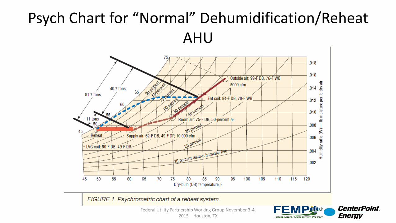
Psych Chart for “Normal” Dehumidification/Reheat AHU
Federal Utility Partnership Working Group November 3-4, 2015 Houston, TX
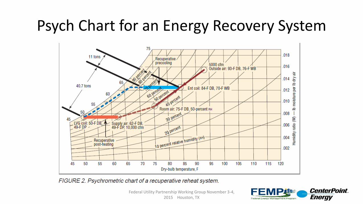
Psych Chart for an Energy Recovery System
Federal Utility Partnership Working Group November 3-4, 2015 Houston, TX