Embed Size (px)
Citation preview

M. Ramgopal
Department of Mechanical Engineering
IIT Kharagpur
Module-2:
Fuels & Combustion

Module Objectives
• For a required power output, the thermodynamic analysis of power plant cycles
yields information on,
– The amount of heat that is to be supplied to the cycle, and
– The temperature at which heat is to be supplied
• The required amount of heat at required temperature is to be provided by a heat
source, that is typically a combustion chamber in which a fuel is burnt
• In this regard, the issues that need to be studied and decided are:
1. What is the type of fuel to be burnt and under what conditions?
2. What is the correct amount of air to be supplied for combustion?
3. What is the type of equipment to be used for combustion?
4. What is the efficiency of the combustion process?
5. What are the effects of the combustion on environment?
6. How to take care of the pollutants that are emitted during combustion?
• The above issues will be addressed in this module
Power plant fuels
• Currently the fuel is the largest cost component of thermal power plants
• Fuels used in the power plants are also the largest contributors to global
warming and other environmental problems
• At present, large thermal power plants use either fossil fuels (coal,
natural gas etc.) or nuclear fuels
• Both fossil and nuclear fuels are non-renewable
– Nature takes millions of years to manufacture fossil fuels
– Nuclear fuels are believed to have originated with the universe!
• The fossil fuels are expected to last at the most for another 200 years at
the current estimates
• The nuclear fuels (fission) are expected to last for 600 years
• Fuels can also be manufactured synthetically from coal, oil shale or tar
sands (synfuels) – believed to offer a cleaner technology!
• Long-term vision is to synthesize fuels using renewable technologies
such as solar – e.g. the hydrogen economy!

Power plant fuels
• Commonly used power plant fuels:
1. Fossil fuels
2. Nuclear fuels
3. Synthetic fuels (Synfuels)
4. Agro based bio-fuels
• Of the above, fossil fuels are the most important and
are expected to remain important for few more
decades!
Fossil Fuels
• “Fossil fuels are the result of anaerobic decay of geologically
deposited plant and animal matter that underwent metamorphism
over geologic time under lithostatic pressure and temperature” Paul Kruger, Alternative Energy Resources, John Wiley & Sons, 2006

Fossil Fuels & issues
• The 3 most important fossil fuels are:
1. Coal
2. Crude oil, and
3. Natural gas
• Currently more than 80 % of world’s energy needs are met by
fossil fuels
• The dependence on fossil fuels is expected to increase in coming
years with industrialization of developing countries
• However, fossil fuels are non-renewable
• Though it is extremely difficult to predict how long the fossil fuels
are going to last, some estimates put this as 200 years!
• Thus a frantic search is on for a sustainable solution

Concepts of Hydrogen Economy
Zuttel et al., Hydrogen: The future Energy Carrier, Phil. Trans. R.Soc A(2010)368, 3329–3342
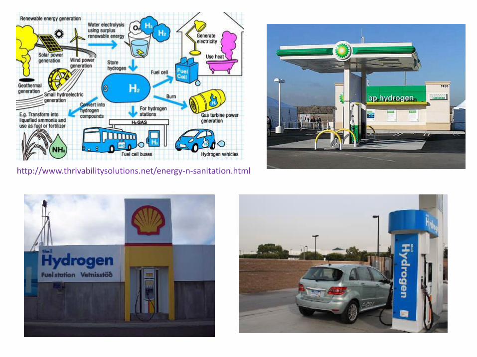
http://www.thrivabilitysolutions.net/energy-n-sanitation.html

Zuttel et al., Hydrogen: The future Energy Carrier, Phil. Trans. R.Soc A(2010)368, 3329–3342

Fossil Fuels

Fossil Fuels (contd.)
Fossil Fuels and Combustion
• For combustion analysis, the properties of fuels are required
• The most fundamental property that is required is the
chemical composition of the fuel
• The simplest of the fossil fuel is natural gas, which is mostly
methane
• The chemical composition of natural gas and other gaseous
fuels can vary, but can be determined relatively easily
• The chemical composition of liquid and solid fuels are very
difficult to determine as they are based on a complex mixture
of various substances
• Generally, the composition of solid fuels is obtained in terms
of proximate analysis or ultimate analysis of fuels

Proximate vs Ultimate Analysis
• Proximate analysis may be called as engineer’s physical analysis
• Proximate analysis gives the percentages, by weight, of moisture,
volatile matter, fixed carbon and ash
• Volatile matter is that part of the coal which is driven off as a gas
when the coal is heated – volatile matter may consist of carbon
• Coke, which is left after heating and removal of volatile matter
consists of fixed carbon and ash
• The sum of the carbon in volatile matter and the fixed carbon in coke
is called total carbon
• Ultimate analysis may be called as chemist’s quantitative
analysis
• Ultimate analysis may be gives percentages by weight of total
carbon, hydrogen, oxygen, nitrogen, sulfur and ash

Example
• A certain coal contains 13 % of moisture and 15 % ash (by weight)
on as received basis. The analysis of the coal on moisture and ash
free basis is shown below. Carry out proximate and ultimate
analyses on as received basis.
Moisture & Ash Free basis
V.M F.C C H2 O2 N2 S
47.9 52.1 77.0 5.5 9.7 1.5 6.3
• Proximate analysis:
• % combustible = 100(13+15) = 72 %
• on an “as received basis”, • % V.M = 0.479 x 72 = 34.5 %
• % F.C = 0.521 x 72 = 37.5 %
• % Moisture = 13.0 %
• % Ash = 15.0 %

Example (contd.)
• Ultimate analysis: % combustible = 100(13+15) = 72 %
• on an “as received basis”, • Total Carbon = 0.770 x 72 = 52.44 %
• Hydrogen = 0.055 x 72 = 3.96 %
• Oxygen = 0.097 x 72 = 6.98 %
• Nitrogen = 0.015 x 72 = 1.08 %
• Sulfur = 0.063 x 72 = 4.54 %
• Moisture = 13.0 %
• Ash = 15.0 %
• Total = 100.0 %
Moisture & Ash Free basis
V.M F.C C H2 O2 N2 S
47.9 52.1 77.0 5.5 9.7 1.5 6.3


Solid Fossil Fuels
• Coal is the largest solid fossil-fuel energy resource on earth
• Coal is also the most widely used fuel in thermal power plants. In India,
approximately 1,50,000 MW of power is generated in coal based power plants
• The term “Coal” covers a large number of solid, organic materials with widely
varying composition and properties
• As per American Society for Testing and Materials (ASTM) coal can be broadly
classified based on its rank (highest to lowest) as:
1. Anthracite (Shiny black, dense, hard and brittle and Slow and clean burning. Carbon: 86
to 98 %, Volatile Matter: 2 to 14 %, HHV: 27.8 MJ/kg )
2. Bituminous coal (Greyish black and soft, Burns easily. Carbon: 46 to 86 %, Volatile
Matter: 20 to 40 %, HHV: 25.6 to 33.3 MJ/kg)
3. Sub-bituminous (Brownish black, Burns easily. High moisture content (15 to 30 %), HHV:
19.3 to 26.7 MJ/kg)
4. Lignite (Brown and laminar in structure. High moisture content (30 % or higher) and
volatile matter (upto 30 %). HHV: 14.6 to 19.3 MJ/kg)
5. Peat (Heterogeneous material consisting of decomposed plant and inorganic material.
Very high moisture content (upto 90%)

Coal (contd.)
Anthracite Bituminous Sub-bituminous
Lignite Peat

Coal Formation (300 – 360 million years)
http://www.zmescience.com/science/geology/how-coal-is-formed/

A view of Murton colliery near Seaham, United Kingdom, 1843. (Source: wikipedia)
Though the existence of coal is known for thousands of years,
its large scale commercial use started in 18th century

Over 1 million deaths annually due to coal pollution (WHO, 2008)

Coal production trends 1980-2012 in the top five coal-producing countries (US EIA)

Indian Coal
• The coal commonly used in Indian power plants is either bituminous or sub-bituminous, even though lignite is also used to some extent
• Indian coal is graded into 7 types based on the calorific value, with the highest grade coal, Grade A having a calorific value greater than about 26 MJ/kg and the lowest grade coal, Grade G having a calorific value of 5.4 to 10 MJ/kg
Higher the fixed carbon, higher is the calorific value of the coal
Higher the moisture content, lower is the calorific value. However, moisture in coal helps in
binding the fine coal and improves radiation heat transfer
Ash in coal affects combustion and boiler efficiency, increases handling costs and causes
clinkering and slagging
Volatile matter in coal helps in ignition of coal, increases flame length and sets a lower limit on the
furnace height

Coal Mining
• Coal is found deep inside the earth in layers
called as “seams”. • The seams may be horizontal or at an angle
• When the coal seams are at an angle, drift
mines are developed by a making a road at
an angle from the surface
• Open cast mining is used in places where
the coal seams are closer to the surface
• In open cast mines, the top rocky layer
covering the coal seams is removed to
facilitate mining of coal
• Deep mines use vertical tunnels or shafts
• Miners, mine equipment and mined coal are
transported underground along horizontal
roadways to the vertical shafts.
A drift mine
An open cast mine
A deep mine

Coal Mining in India
•The 1st coal mine was established in
1774 by M/s Sumner and Heatly of East
India Company in the Raniganj Coalfield
along the Western bank of river Damodar
•The coal mines were nationalized in
1971-73
•In 2009, India with 526 Mt, was the 3rd
biggest hard coal producer after China
(2971 Mt) and the USA (919 Mt)
•Currently, around 80 % of the Indian coal
comes from open cast mining
•Around 75 % of the coal mined in India is
used by the energy sector with the
remaining in steel and other industries
•However, due to low quality and
increasing domestic consumption,
India imports a large amount of coal
(about 85 Mt in 2011)

Coal storage
• Due to uncertainty associated with
availability and transport, all coal based
power plants stockpile coal sufficient for 7
to 45 days
• Most of the coal stockpiles are open type
and are formed by rail mounted stackers
• Storage of large quantities of coal is
associated with problems related to:
– Carryover of the fine dust particles by
wind
– Spontaneous combustion of coal due
to self oxidation
– Decreased heating value and
increased ignition temperature due
to oxidation etc.
• Minimizing the amount to be stocked,
proper compaction and stocking
methods and early detection of self-
ignition reduces the risk of coal fires
http://www.tce.co.in/Coal stockpile in Indian power plants.pdf
Self-ignition of coal

Coal Firing in coal based power plants
https://www.deeptrekker.com

FGD scrubber
Components of a coal based power plant
Steam Boiler
Coal Supply &
Preparation
Coal Furnace
Steam Turbine
Generator
Condenser &
Cooling Tower
De NOx ESP*
Dust Removal
FGD SOx
Flue Gas
Coal
Air
Power Heat Rejection
Ash
Solid
residual matter
ESP: Electro static precipitator
De NOx: Selective catalytic (SCR) or selective non-catalytic
converter (SNCR) system for removal of NOx. NOx causes
formation of Ozone in troposphere and also causes acid rain
FGD SOx: Flue Gas Desulphurization system. SOx in the
atmosphere causes corrosion, acid rain, and other
environmental problems

Movement of coal in the coal based power plant
Coal Storage
(7 – 45 days stock)
Coal Bunker
(1 day stock)
Coal
feeders
Drying &
Pulverizing mills
Hot air (350 – 400oC)
Coal firing
furnace
Secondary air
Ash &
Flue gases

Coal Firing
• Coal is fired in a variety of coal furnaces
• The issues to be considered in the design of coal furnaces are:
1. Combustion efficiency – complete combustion
2. Handling of ash
3. Handling of SO2
4. Handling of NOx
5. Capacity control, and
6. Effect on downstream components (e.g. steam generator)
• The design of the combustion chamber must ensure that:
1. Temperature inside is high enough so that ignition of coal can be initiated and
sustained
2. Turbulence inside the chamber is high enough to ensure proper mixing of coal
particles and the oxidizer (air), and
3. Time, sufficient for the combustion process to be completed is available for the
coal

• The 5 steps in coal combustion process
1. Drying – evaporation of surface water & water in pores (100 to
300oC)
2. Pyrolisis – decomposition of organic substances in coal and
formation of gaseous products (300 to 600oC)
3. Ignition – Initiation of the process of combustion of both volatile
matter and residual char (carbon + ash forming materials) (500 to
900oC)
4. Combustion of volatile matter (above 800oC)
5. Combustion of the residual char (900 to 1400oC)
• In an actual furnace, there could be overlap of the above
processes
• Depending upon the furnace type and particle size the entire
combustion of the particle may take 1 to 1000 seconds
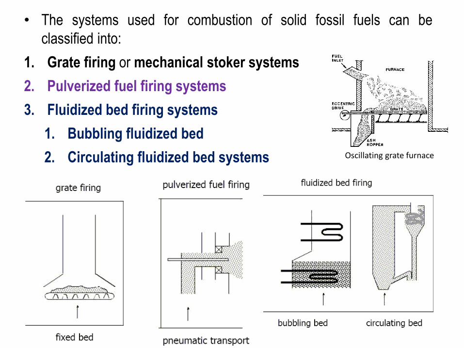
• The systems used for combustion of solid fossil fuels can be
classified into:
1. Grate firing or mechanical stoker systems
2. Pulverized fuel firing systems
3. Fluidized bed firing systems
1. Bubbling fluidized bed
2. Circulating fluidized bed systems Oscillating grate furnace

1. Mechanical Stoker or Grate Furnaces:
• All types of coal can be fired in mechanical stokers
• However, stokers have low combustion efficiency and low burning rates
– Limited to lower steam generation rates ( < 50 kg/s)
Spreader stoker with travelling grate Chain-grate stoker

2. Pulverized Coal (PC) Furnace systems:
– Development of PC systems can be considered as a landmark event in the
development of coal fired steam power plants
– It is based on the idea that coal can be made to burn cleanly and
efficiently like a gas, if the particle size of the coal can be reduced
significantly –Energy required for pulverization - Rittinger’s law!
– In PC systems the coal is first pulverized to a size of 200 mesh (particle
size less than 70 microns) or less and then burnt in the PC furnace
– The complete system consists of:
1. A Pulverizer
2. A Delivery system for pulverized coal, and
3. Burning equipment
– Coal from the bunker is continuously fed to the pulverizer and then to the
furnace through the burners using primary air
– The pulverized coal carried by the primary air enters the furnace through
the burner and mixes there with main combustion air coming from the pre-
heater of the steam generator
– Initial ignition is achieved by a variety of ways, e.g. use of a light-fuel oil jet

i. Depending upon the type and capacity there may be
one or more than one burners, arranged in a variety
of ways
ii. The burners can be used to burn only PC fuel or any
other fuel, e.g. oil or gas
iii. The burners are designed to produce turbulence and
thorough mixing and efficient combustion
iv. Due to the above, the excess air requirement is much
less in PC furnaces, compared to stoker furnaces
Pulverized coal burner http://navier.engr.colostate.edu
Pulverized coal firing system
PC Furnace with 4 tangential burners

3. Cyclone Furnace:
• Cyclone furnace is widely used for burning low-
grade coals, e.g. coals with high ash content
(as high as 25%) and a high volatile matter
(>15%)
• The coal need not be pulverized
• However, the coal should have low sulfur
content
• The tangential entry of high speed primary and
secondary air impart centrifugal motion to coal
particles
• The whirling motion of air and coal leads to
large heat release rates in small volume (as
high as 8000 kW/m3), leading to high
combustion temperatures ( around 1650oC)
• The main advantage of this furnace is the removal of almost 60 % of the ash formed as slag,
collected on the furnace walls due to centrifugal action and drained off through the bottom
• Only 40 % of the total ash leaves the furnace along with the flue gases, which reduces the
fouling of the boiler substantially.
• Also the size of the filtration system at steam-generator exit reduces drastically
• However, as the combustion temperatures are much higher in this furnace comapred to others,
there is a danger of NOx formation
Cyclone Furnace

4. Fluidized bed combustion (FBC): • In these systems, the combustion takes
place with coal particles in a suspended
state - Fluidization
• Fluidization is achieved by maintaining
suitable velocities such that the buoyancy
and drag force are balanced – Minimum
fluidization velocity
• In fluidized bed combustion, crushed coal in
the range of 6 to 20 mm is injected into the
bed just above the air distribution grid
The products of combustion leaving the furnace contain large amount of unburnt coal,
which is returned back to the furnace by the cyclone dust collector
One major advantage of FBC is the removal of sulfur (which forms SO2 during
combustion) in the furnace itself by the addition of lime stone (CaCO3) directly to the
bed with coal
CaCO3 + SO2 + (1/2)O2 = CaSO4 + CO2
CaSO4 produced in the above process is a dry waste product that can be disposed off
Since the combustion temperature is much lower, low grade coals can be used and the
formation of NOx is minimized.

4. Fluidized bed combustion (contd.): • Fluidized bed combustion yields high
combustion efficiency at low combustion
temperatures
• Also there is no need for pulverizing the coal
• Also the boiler can be integrated with the
furnace resulting in very high volumetric heat
transfer rates (10 to 15 times higher than
conventional boilers) - very compact
• Due to absence of sulfur in exhaust, lower
stack gas temperatures can be tolerated
leading to high overall plant efficiency
However, proper design and control of fluidized bed boilers are difficult and complex
Some of the important issues that need to be addressed are:
Proper feeding of coal and limestone particles together into the bed
Proper control of coal particle carry-over with the flue gases
Regeneration or disposal of calcium sulfate
Quenching of combustion by the cooler water tubes inside the bed, and
Operation under variable loads
Fluidized bed furnace integrated with boiler
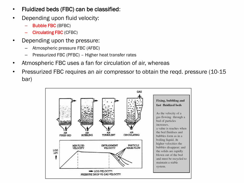
• Fluidized beds (FBC) can be classified:
• Depending upon fluid velocity: – Bubble FBC (BFBC)
– Circulating FBC (CFBC)
• Depending upon the pressure: – Atmospheric pressure FBC (AFBC)
– Pressurized FBC (PFBC) – Higher heat transfer rates
• Atmospheric FBC uses a fan for circulation of air, whereas
• Pressurized FBC requires an air compressor to obtain the reqd. pressure (10-15
bar)

Output ranges of different firing systems
Firing system Output range (MW)
Grate firing 2.5 to 175
Pulverized fuel firing 40 to 2500
Bubbling fluidized bed firing Up to 80
Circulating fluidized bed firing 40 to 750
Source: Power generation from solid fuels, H. Spliethoff, Springer (2010)
• Currently most of the large coal based power plants use Pulverized fuel firing only
• Recently Neyveli Lignites Corporation (NLC) has introduced the Circulating Fluidized
Bed (CFB) Boiler of around 300 MW capacity in India (made by BHEL)

Liquid fuels
• Most of the commonly used liquid fuels are mixtures of hydrocarbons
with the generic formula CnHm (m is a function of n)
• Crude oil is a mixture of an extremely large no. of hydrocarbons
• Crude oil mainly consists of C (83 to 87 %) and H (11 to 14 %) with
some amount of O, N, S and H2O
• Crude oil is fractionally distillated or cracked into:
– Petrol, Aviation Kerosene, Diesel, Fuel oil, Lubricating oil etc
• Liquid fuels are easier to handle and store
• Liquid fuels burn easily & have narrow heating values (43 to 46 MJ/kg)
• The important properties are:
– specific gravity, viscosity, pour and flash points
• Normally emulsion firing is used for heavy oils – for good atomization
• However, due to scarcity of oil, high fuel costs and need for oil in other
applications, oil fired power plants are getting converted into coal or
other alternate fuel fired plants

Gaseous fuels
• The commonly used gaseous fuels are:
– Natural gas
– Producer gas (A combustible mixture of nitrogen, carbon monoxide, and hydrogen, generated by passing air with steam over burning coke or coal in a furnace)
– Blast furnace gas (a by-product of blast furnaces that is generated when the iron ore is reduced with coke to metallic iron)
– Coke oven gas ( a fuel that is produced during the manufacture of metallurgical coke by anerobic heating of bituminous coal to about 1000oC )
• Natural gas (95 % or more CH4) is most widely used gaseous fuel
• Natural gas (NG) has high heating value (about 39 MJ/m3)
• NG mixes readily with air does not produce soot or smoke
• NG can be stored in liquefied form (LNG), in compressed form (CNG) or in adsorbed form (ANG)
• Other gaseous fuels e.g., Coke oven gas, producer gas etc can be produced from coal – coal gasification
• Hydrogen is one of the fuels considered for future applications
• Due to clean combustion and environmental benefits, there is an increasing interest in gaseous fuels obtained from coal or other sources

Agro-based fuels
• These include:
– Bagasse
– Paddy husk
– Saw dust
– Coconut shell
– Deoiled bran etc.
• The typical calorific values of these fuels vary from about 13 MJ/kg to 20 MJ/kg
• The biomass obtained from the agro-products can be converted into gaseous or
liquid fuels by using a variety of conversion techniques such as:
– Thermochemical conversion
– Biochemical conversion
– Fermentation etc.

https://wattsupwiththat.com

Combustion
Combustion in pulverized coal furnace
Combustion is a highly complicated chemical reaction in which the oxygen in air
combines chemically with the carbon, hydrogen, sulfur and other combustible elements of
the fuel producing CO, CO2, H2O, SO2, ash etc. in addition to light & heat at high
temperature
Combustion in a coal fireplace

Combustion calculations
• Combustion is a rapid chemical reaction between a fuel and an
oxidizer resulting in the production of heat and light
• The heat released during combustion must be transferred in an
efficient manner to the working fluid in the boiler
• Combustion process is the most fundamental, yet one of the most
complex processes in a fossil fuel based power plant
• For high overall plant efficiency and clean environment, the
combustion process must be carefully controlled and managed
• Ideally, there should be no unburnt fuel at the end of the
combustion process – complete combustion

Combustion calculations
• In power plant furnaces, the oxygen in air is used as the oxidizing
agent
• For complete combustion in a furnace:
1. Adequate quantity of air must be supplied to the fuel,
2. Air and fuel must be thoroughly mixed,
3. The fuel and air mixture must be maintained above the ignition
temperature, and
4. Furnace size should be large enough so that enough residence
time is available for complete combustion
• All fuels generally constitute elements, some of which are
combustible, while the others are not
• The type and amount of combustible and non-combustible
elements vary from fuel to fuel
• Thus the amount of air required for complete combustion also
varies from fuel to fuel
Combustion calculations
• The minimum amount of air required for complete combustion is called
as stoichiometric air
• The stoichiometric air for a fuel has to be obtained by applying
fundamental balance equations to the combustion reaction
• To apply the balance equations, the chemical composition of the fuel
must be known from the ultimate analysis
• Since perfect mixing of fuel and air are almost impossible under actual
conditions, the amount of air required for complete combustion is
generally much more than stoichiometric air
• The excess air required for complete combustion depends upon the fuel
type, load on the boiler and type of firing equipment
• The excess air quantity must be carefully assessed to minimize losses
and maximize plant efficiency

Combustion calculations – Composition of air
Standard composition of atmospheric air used for combustion (1952)

Combustion Stoichiometry
• Combustion reactions:
• The reactions between the combustible elements of the fuel and
oxygen (in air) obey the following basic principles:
1. Specific compounds form in fixed composition when two or
more reactants combine (stoichiometry)
2. The mass of any element in the reactant equals the mass of that
element in the products (conservation of mass)
3. Chemical compounds form from elements combining in fixed weight
relationships (law of combining weights)
4. Depending upon the change of free energy for the reaction,
formation of a compound may produce heat (exothermic) or may
consume heat (endothermic)

Combustion Stoichiometry
• For simple hydrocarbon fuels (CnHm), complete combustion results in
the formation of CO2 from all of the carbon and H2O from all of hydrogen
• However, since the fuels burn in air, one has to account for the
presence of N2 in air
• For simple hydrocarbon fuels, considering std. air with only N2 and O2,
the stoichiometric reaction is:
• Thus for every mole of fuel burnt, 4.78(n + m/4) moles of air is required
for stoichiometric combustion
• In the above reaction, it is assumed that N2 does not take part in the
reaction. However, this may not be true always!

• The mole fractions of the products for the above reaction are:
• The mass of stoichiometric air reqd. for the hydrocarbon CnHm is:
• The stoichiometric fuel-air ratio ( mf/ma in kg/kg) for CnHm is given by:
• If the fuel consists of other elements, which participate in the
combustion, then they too must be taken into account in the calculations
• For example,

Combustion calculations
Typical combustible substances and compounds formed

Example: Combustion calculations for Coal
• The ultimate analysis of a sample of coal is as
shown. Find a) the stochiometric fuel/air ratio
(mass basis), b) the mole fractions of the species in
the products, and c) Dew point temperature of
products of combustion assuming the reaction to
occur at 101 kPa.
• Assume:
1. Complete combustion
2. Non-participation of N2 in reaction
3. Formation of only SO2 from S
4. Non-participation of ash in the combustion reaction

Solution: Combustion calculations for Coal (contd.)
Based on the composition, atomic wts. and normalization with respect to C:
The chemical formula of the fuel is CH0.808N0.013S0.013O0.057
The mass of the fuel per mol of C = 100/6.43 = 15.55 g/mol C
Step 1: Find the chemical composition of the fuel by normalizing each constituent element
with respect to carbon C.

Example: Combustion calculations for Coal (cond.)
The stoichiometric combustion equation for the fuel CH0.808N0.013S0.013O0.057 is
where
a) the fuel/air ratio for stoichiometric combustion is:
b) The total no. of moles of products per mol of C
= 1 + 0.404 + 0.013 + (1.19 x 3.78 + 0.0065) = 5.921
The mole fractions of species in the products of combustion are:
CO2 = (1/5.921) = 0.169; H2O = (0.404/5.921) = 0.068; SO2 = (0.013/5.921) = 0.00220
N2 = 4.504/5.921 = 0.761
c) Partial pressure of water vapour = 0.068 x 101 = 6.868 kPa DPT = 38.6oC

Need for excess air
• Stoichiometric air is sufficient for complete combustion only when the mixing between the fuel and air is perfect
• As obtaining perfect mixing in actual furnaces is impossible, the amount of air supplied should be more than stoichiometric air
• Since the amount of air required for complete combustion varies from fuel to fuel, for comparison purposes, normalized parameters are used
• If the equivalence ratio is less than 1, then the mixture is called as lean mixture (more air than stoichiometric quantity)
• If the equivalence ratio is more than 1, then the mixture is called as rich mixture (less air than stoichiometric quantity)

Need for excess air (contd.)
• When the fuel-air mixture is lean, then the combustion may be complete and the
products may consist of some amount of unreacted O2
• For this case, the composition of the products can be computed approximately
from atomic balance
• However, if the fuel-air mixture is rich, then there will be unburnt combustibles
(e.g., C, CO, H, S etc.) present in the products
• This implies that the product analysis of rich fuel-air mixture cannot be done based
on atomic balance alone as the composition depends upon additional
thermodynamic and chemical kinetic considerations

Heating or Calorific value of a fuel
• The Heating Value (HV) of the fuel is commonly used in power plant
calculations and for comparing different fuels
• The heating value is defined as the “heat transferred per unit mass of fuel
when the products of complete combustion of a sample of fuel are cooled
to the initial temperature of air and fuel”
• The heating value may be found on an as-received, dry or dry-and-ash-free
basis
• The heating value is normally obtained from measurements using a Bomb
calorimeter or a Boys calorimeter
• Depending upon the state of water in the products of combustion, the
heating value may be either gross or higher heating value (HHV) or lower
heating value (LHV) – HHV means water vapour in reactants is condensed

Heating or Calorific value of a fuel
• The HHV (in kJ/kg) and LHV (in kJ/kg)) are related by the equation:
LHV = HHV mw x hfg = HHV 9 x mH2 x hfg
where:
• mw = mass of water vapour in products of combustion per unit mass of
fuel due ONLY to combustion of H2 in fuel (not initial H2O) (kg/kg)
• mH2 = mass of original hydrogen in fuel per unit mass of fuel as known
from ultimate analysis (kg/kg)
• hfg = latent heat of vapourization of water vapour at its partial pressure
in the products of combustion (kJ/kg)
• The partial pressure of water vapour in the products of combustion is
obtained by multiplying the mole fraction of H2O in the products of
combustion with the total pressure of the products
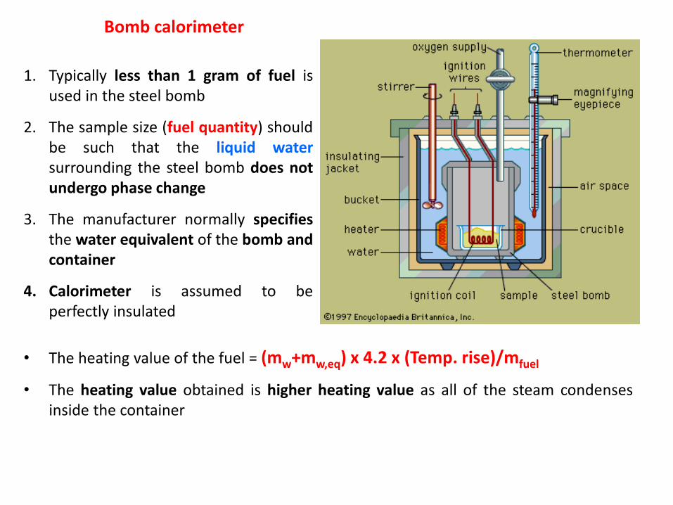
Bomb calorimeter
1. Typically less than 1 gram of fuel is
used in the steel bomb
2. The sample size (fuel quantity) should
be such that the liquid water
surrounding the steel bomb does not
undergo phase change
3. The manufacturer normally specifies
the water equivalent of the bomb and
container
4. Calorimeter is assumed to be
perfectly insulated
• The heating value of the fuel = (mw+mw,eq) x 4.2 x (Temp. rise)/mfuel
• The heating value obtained is higher heating value as all of the steam condenses
inside the container
Heating or Calorific value of a fuel
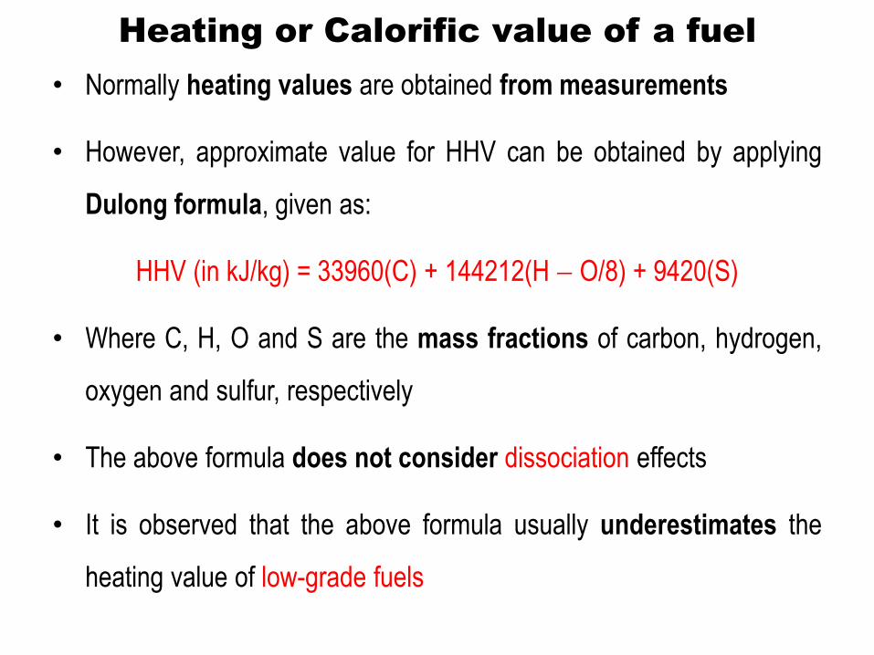
• Normally heating values are obtained from measurements
• However, approximate value for HHV can be obtained by applying
Dulong formula, given as:
HHV (in kJ/kg) = 33960(C) + 144212(H O/8) + 9420(S)
• Where C, H, O and S are the mass fractions of carbon, hydrogen,
oxygen and sulfur, respectively
• The above formula does not consider dissociation effects
• It is observed that the above formula usually underestimates the
heating value of low-grade fuels

Example: Calorific value of Coal
• The ultimate analysis of a sample of coal is as shown.
Find the higher and lower calorific values and dew
point temperature of products
• Assume:
1. Complete combustion
2. Non-participation of N2 in reaction
3. Formation of only SO2 from S
4. Non-participation of ash in the combustion reaction
Solution:
Step 1: Find the chemical composition of the fuel by
normalizing each constituent element with respect to
carbon C.
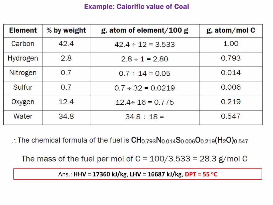
Example: Calorific value of Coal
Ans.: HHV = 17360 kJ/kg, LHV = 16687 kJ/kg, DPT = 55 oC

Thermodynamics of combustion processes
• Though knowledge of heating values is useful, in an actual power
plant the products of combustion are not cooled to the initial
conditions HV of fuel is not completely available!
• Knowledge of the combustion temperature is essential in the design
of the components and selection of materials and also in the
control of emissions
• The actual composition of the combustion products do not always
follow simple chemical balances
• Information regarding the above can be obtained by applying laws
of thermodynamics to the combustion processes

Combustion and 1st Law of Thermodynamics
Reactants
Products
Combustion
chamber
Q
Wsf
1st Law of Thermodynamics applied to a steady-state steady-flow reactive system
(combustion chamber), neglecting changes in KE and PE;
where HR and HP = Total enthalpy rate of reactants and products, respectively in kW
Q = Net heat transfer rate to the system (combustion chamber) in kW
Wsf = Net steady flow work transfer rate from the system in kW
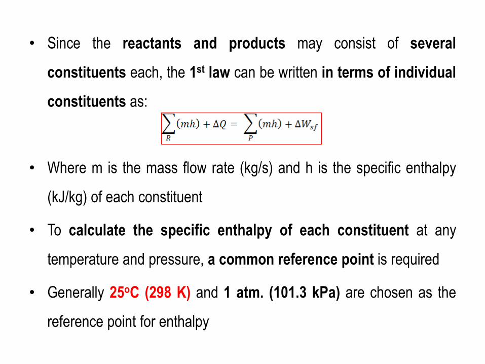
• Since the reactants and products may consist of several
constituents each, the 1st law can be written in terms of individual
constituents as:
• Where m is the mass flow rate (kg/s) and h is the specific enthalpy
(kJ/kg) of each constituent
• To calculate the specific enthalpy of each constituent at any
temperature and pressure, a common reference point is required
• Generally 25oC (298 K) and 1 atm. (101.3 kPa) are chosen as the
reference point for enthalpy
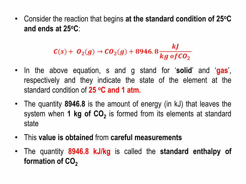
• Consider the reaction that begins at the standard condition of 25oC
and ends at 25oC:
• In the above equation, s and g stand for ‘solid’ and ‘gas’, respectively and they indicate the state of the element at the
standard condition of 25 oC and 1 atm.
• The quantity 8946.8 is the amount of energy (in kJ) that leaves the
system when 1 kg of CO2 is formed from its elements at standard
state
• This value is obtained from careful measurements
• The quantity 8946.8 kJ/kg is called the standard enthalpy of
formation of CO2
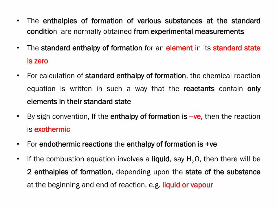
• The enthalpies of formation of various substances at the standard
condition are normally obtained from experimental measurements
• The standard enthalpy of formation for an element in its standard state
is zero
• For calculation of standard enthalpy of formation, the chemical reaction
equation is written in such a way that the reactants contain only
elements in their standard state
• By sign convention, If the enthalpy of formation is ve, then the reaction
is exothermic
• For endothermic reactions the enthalpy of formation is +ve
• If the combustion equation involves a liquid, say H2O, then there will be
2 enthalpies of formation, depending upon the state of the substance
at the beginning and end of reaction, e.g. liquid or vapour

Important Note: Standard enthalpy of formation of a substance is the
enthalpy change for the formation of one mole of the substance in its
standard state from its constituent elements in their standard state
Standard enthalpies of formation of some substances

• Since chemical reactions are balanced in terms of moles, rather
than masses, it is convenient to write the equation in terms of
molar quantities
• Where n and M are the number of moles and molecular weight of the
species, respectively
• In terms of molar enthalpies of formation, (kJ/mol)

• If the reaction takes place at temperatures other than the standard
conditions, then an additional term that accounts for the sensible heat
due to temperature change must be included in the reaction
calculations,
• thus for conditions other than standard state,
• Calculations can be done using:
1. Tabulated values of enthalpy of formation for different temperatures
2. Using specific heats and temperature difference
• Since specific heat varies with temperature, it can be expressed
approximately as:

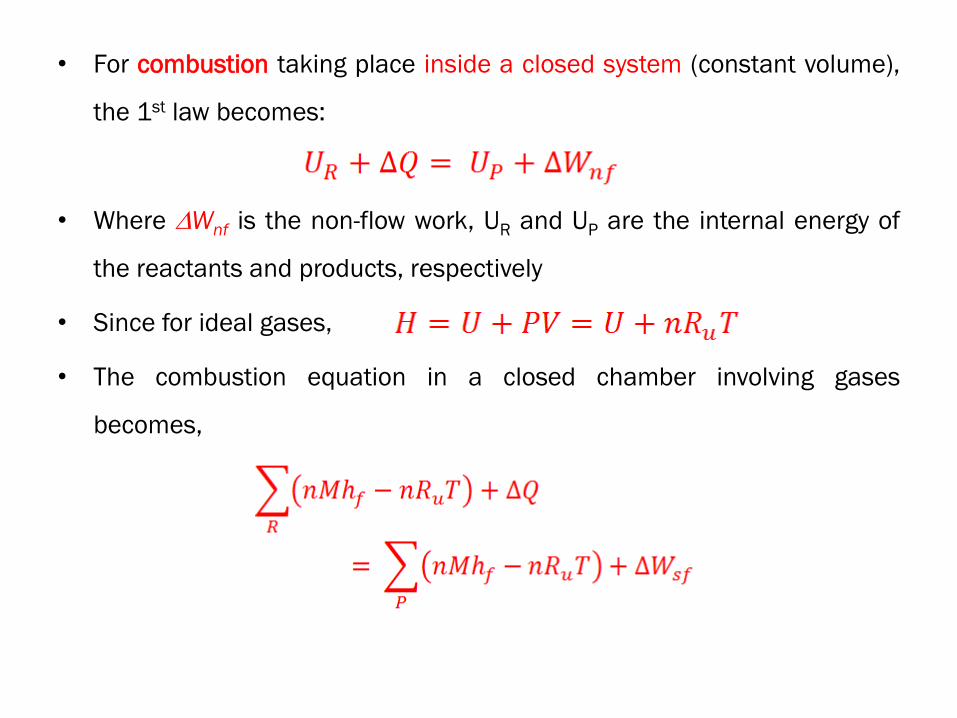
• For combustion taking place inside a closed system (constant volume),
the 1st law becomes:
• Where Wnf is the non-flow work, UR and UP are the internal energy of
the reactants and products, respectively
• Since for ideal gases,
• The combustion equation in a closed chamber involving gases
becomes,

Heating values
• Heating value is defined as “the heat released during complete
combustion with both reactants and products at standard state of 298 K
in a steady flow, adiabatic system without work”
• Thus from the 1st law:
• Since the above equation is defined for an open system, it is also called
as enthalpy of combustion
• For a closed system, the heating values HVnf, obtained from 1st law is:
• Where nP and nR are the total number of moles in the products and
reactants, respectively

Example-1
1. Find the heating value of propane, using the given standard enthalpies
of formation. Assume combustion in an open furnace. Compare the
value obtained with that calculated using Dulong formula.
HHV (in kJ/kg) = 33960(C) + 144212(H O/8) + 9420(S)
Ans.: 50369 kJ/kg (54004 kJ/kg from Dulong’s formula)

Example-2
Find the useful heat transferred to the working fluid of a steam generator by
the combustion of 1 kg of ethane in a furnace with an equivalence ratio of
1.25 (rich mixture). Assume that due to higher reactivity, the tendency of H
forms H2O completely is higher compared to C forming CO2. The reactants are
at 25oC, while the products are at 1500 K. Assume a furnace efficiency of 95
%. Given at 1500 K, enthalpy of formation (in kJ/kg) of:
CO2 = -7546.3, CO = -2560.517, H2O = -10760, N2 = +1374.106
Standard enthalpy of formation
Ans.: 11052 kJ/kg

Example-3
In a constant volume bomb calorimeter propane is burned with pure O2 and
the heat of combustion is transferred to surrounding water. If measurements
show that the heat transferred to the surrounding water is 2043 MJ/kgmol,
find the enthalpy of formation of propane. Assume standard conditions for
the reaction.
Standard enthalpy of formation

Temperature of products of combustion
• Knowledge of temperature of products of combustion is essential
– in the design of combustion chamber and downstream equipment, and
– for control of emissions
• For a given combustion reaction in a furnace, the temperature of
the products of combustion depends upon the heat transfer rate
• Knowing the heat transfer rate, the temperature of products can
be obtained using the values of enthalpy of formation at different
temperatures and a trial-and-error method
• Enthalpy of formation at different temperatures can be obtained from
tables, charts or equations

hf is in kJ/kg

• Using the tabulated values and regression, the following equation
is obtained for enthalpy of formation

Worked out example
P. The volumetric analysis of a gaseous fuel shows the following
composition:
CO: 22.9 %; H2: 10%; CO2: 4.4%; N2: 62.7%
The gas enters a furnace at 800K and burns with 100 % theoretical
air at 25oC. If the heat transfer rate from the furnace to the
surroundings is 399 kJ/m3, find the temperature of the product gases
at the exit of the furnace.
Ans. Since molar and volumetric compositions are equal for gases; the
combustion equation with 100% theoretical air is:
. 𝐶 + . 𝐻2 + . 𝐶 2 + . 2 + . + . 2 + . + . . 2→ . + . 𝐶 2 + . 𝐻2 + . + . . + . 2 . 𝐶 + . 𝐻2 + . 𝐶 2 + . 2 + . 2 + . 2→ . 𝐶 2 + . 𝐻2 + . 2


• Using the regression equation,
• We find at 800 K the enthalpy of formation of CO, H2, CO2 and N2 are: 3398
kJ/kg, 7258 kJ/kg, 8414 kJ/kg and 544.8 kJ/kg, respectively
Using the equations for enthalpy of formation, the product gas temperature is found to be: 2082 K
∴ 𝑛 ℎ𝑓𝑅 = . × . × + . × . × + . × .× + . × . × . = − 𝐉/ 𝐠. 𝐨 ∴ 𝑛 ℎ𝑓 = − . + − = − . kJkg.mol = − . 𝒌𝑱𝒌𝒈
𝑛 ℎ𝑓 = . × . × ℎ𝑓, 2 + . × . × ℎ𝑓,𝐻2 + . × . × ℎ𝑓, 2= − . 𝒌𝑱𝒌𝒈

Adiabatic Flame Temperature
• The combustion temperature will be maximum when combustion takes
place adiabatically
• This maximum temperature is called as Adiabatic Flame Temperature or
Adiabatic Combustion Temperature
• In practice, the combustion temperature can never reach the adiabatic
flame temperature because:
1. Perfectly adiabatic system is impossible to construct
2. Complete combustion is impossible due to non-zero heat and mass
transfer resistances
3. The combustion products will ionize at high temperatures, and this being
an endothermic process, the combustion temperature decreases

Adiabatic Flame Temperature (contd.)
• Nevertheless, adiabatic flame temperature provides a useful upper
bound on combustion temperature
• It is used to:
1. For proper material selection considering the thermal effects of
combustion temperatures
2. For estimation and control of emissions from the power plants
• Adiabatic flame temperature (TADB) is obtained by trial-and-error; from the
1st law as:
• From the above equation, knowing the state of the reactants completely,
the adiabatic flame temperature can be obtained by trial-and-error
method using the enthalpy of formation – temperature relations
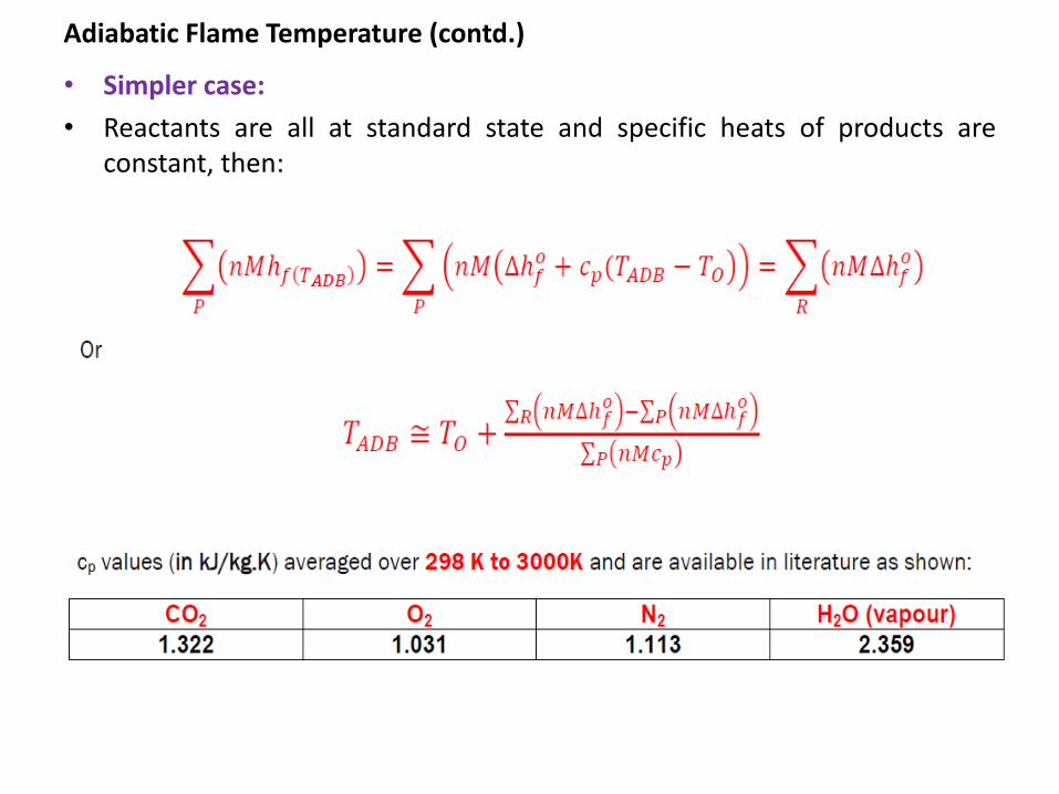
Adiabatic Flame Temperature (contd.)
• Simpler case:
• Reactants are all at standard state and specific heats of products are
constant, then:

Adiabatic Flame Temperature (contd.)
• If the combustion takes place inside a closed chamber of constant
volume, then the adiabatic flame temperature is obtained from the 1st law
of thermodynamics as:
𝑹 = 𝑷
𝑛 ℎ𝑓 − 𝑛𝑅𝑢𝑇𝑅 = 𝑛 ℎ𝑓,𝑇 𝐷 − 𝑛𝑅𝑢𝑇
Assuming ideal gas behavior for products and reactants, the above equation can
be written as:
If the reactants are at standard state and specific heat values are assumed to be constant,
then from the above equation,
𝑇 ≅ 𝑛 ∆ℎ𝑓 − 𝑛𝑅𝑢𝑇 − 𝑛 ∆ℎ𝑓 − 𝑐 𝑇𝑅 𝑛 𝑐 − 𝑛𝑅𝑢

Maximum Explosion Pressure
• The pressure produced in a closed combustion chamber reaches a
maximum value when the combustion temperature equals the adiabatic
flame temperature
• This happens when:
1. The combustion chamber is insulated, and/or
2. The combustion is too fast for any heat transfer to take place, e.g. in
explosions
• Knowledge of Pmax is essential in the safe design of combustion
chambers, calorimeters etc.

Maximum Explosion Pressure
• Assuming ideal gas behavior, the maximum explosion pressure inside a
closed combustion chamber can be obtained as:
• Where np is the total number of moles of products present in the
combustion chamber and V is the volume of the combustion chamber
𝑷 𝒂𝒙 = 𝑷𝑹𝒖 𝑨𝑫𝑭

• In certain applications such as jet engines etc, the kinetic energy
of the products of combustion is kept high deliberately,
• In such cases this term has to be included in the energy balance
• For a steady flow combustion process with negligible kinetic
energy of the reactants and no work transfer, the 1st law can be
written as:
• Where u is velocity of products of combustion at the exit of the
chamber
Combustion with significant change in kinetic energy

1. Find the adiabatic flame temperature for stoichiometric combustion of
carbon (reference) in air in a furnace.
Given:
Standard enthalpy of formation: CO2 = 8946.1 kJ/kg
cp values: CO2: 1.322 kJ/kg.K; N2: 1.113 kJ/kg.K
Ans.: 2535.1 K = 2262oC
Worked out examples

2. Find the adiabatic flame temperature and maximum possible pressure for
stoichiometric combustion of 1 kmol of carbon (reference) in air in a
closed, combustion temperature of 1 m3 volume.
Given:
Standard enthalpy of formation: CO2 = 8946.1 kJ/kg
cp values: CO2: 1.322 kJ/kg.K; N2: 1.113 kJ/kg.K
Ans.: 3186.7 K; 1266.5 bar
3. What should be the mass of carbon if the maximum pressure is not to
exceed 250 bar and the combustion chamber volume is 1 litre?
Ans.: 8.69 g
Example problems

4. Find the adiabatic flame temperature of liquid octane with 100 %
Theoretical Air.
Given:
Standard enthalpy of formation: liquid Octane = 2189.5 kJ/kg
cp values: CO2: 1.322 kJ/kg.K; N2: 1.113 kJ/kg.K
Ans.: 2485.7 K
5. What is the adiabatic flame temperature with 200 % theoretical air?
Ans.: 1509 K
Example problems
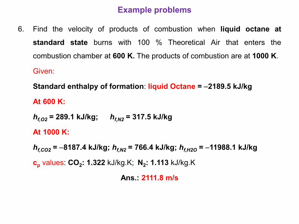
6. Find the velocity of products of combustion when liquid octane at
standard state burns with 100 % Theoretical Air that enters the
combustion chamber at 600 K. The products of combustion are at 1000 K.
Given:
Standard enthalpy of formation: liquid Octane = 2189.5 kJ/kg
At 600 K:
hf,O2 = 289.1 kJ/kg; hf,N2 = 317.5 kJ/kg
At 1000 K:
hf,CO2 = 8187.4 kJ/kg; hf,N2 = 766.4 kJ/kg; hf,H2O = 11988.1 kJ/kg
cp values: CO2: 1.322 kJ/kg.K; N2: 1.113 kJ/kg.K
Ans.: 2111.8 m/s
Example problems

End of Module 2