Embed Size (px)
Citation preview
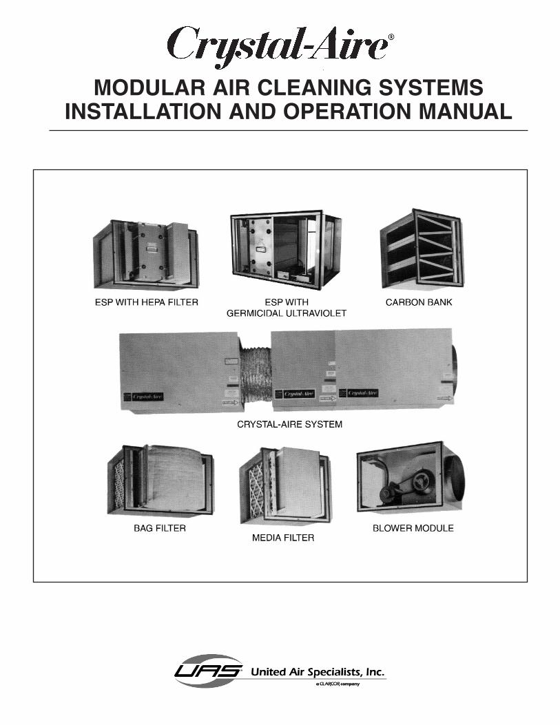
MODULAR AIR CLEANING SYSTEMSINSTALLATION AND OPERATION MANUAL

KNOW YOUR EQUIPMENT
READ THIS MANUAL FIRST.
Your CRYSTAL-AIRE® system should provide many years of trouble-free service. This man-ual will help you understand the operation of your CRYSTAL-AIRE® unit. It will also help youunderstand how to maintain it in order to achieve top performance. For quick future refer-ence, fill in the system and filter information in the spaces below. Should you need assis-tance, call the United Air Specialists, Inc. customer service number shown below. To expe-dite your service, have the following information available when contacting UAS.
UNIT MODEL #:_________________________________________________________
UNIT SERIAL #:_________________________________________________________
SYSTEM ACCESSORIES:
______________________________________________________________________
______________________________________________________________________
______________________________________________________________________
INSTALLATION DATE: ___________________________________________________
UNITED AIR SPECIALISTS, INC. CUSTOMER SERVICE
1-800-252-4647
TABLE OF CONTENTS
SAFETY PRECAUTIONS...........................................................................................i
INTRODUCTION .......................................................................................................1
INSTALLING YOUR CRYSTAL-AIRE® SYSTEM.....................................................1APPLICATION......................................................................................................1INSPECTION .......................................................................................................1UNPACKING ........................................................................................................1INSTALLATION ....................................................................................................2HANGING ............................................................................................................2ASSEMBLING MODULES...................................................................................2ELECTRICAL REQUIREMENTS .........................................................................3
HOW YOUR CRYSTAL-AIRE® SYSTEM OPERATES ............................................3BLOWER MODULE .............................................................................................3ESP MODULE......................................................................................................4ESP MODULE WITH GUV LAMPS .....................................................................4MEDIA FILTER MODULES..................................................................................5ODOR MODULE..................................................................................................5REMOTE INDICATOR LIGHT..............................................................................6PRESSURE SWITCH ..........................................................................................6
CLEANING ................................................................................................................6CLEANING OF COMPONENTS..........................................................................6WHEN ARE COMPONENTS CLEAN? ................................................................7
MAINTENANCE & SERVICE ....................................................................................8BLOWER MODULE .............................................................................................8ESP MODULE......................................................................................................8MEASURING VOLTAGE......................................................................................9REPLACING IONIZER WIRES..........................................................................10DISCHARGING HIGH VOLTAGE COMPONENTS............................................11BOX AND BAG FILTER MODULES...................................................................11
TROUBLESHOOTING GUIDE................................................................................12
REPLACEMENT PARTS.........................................................................................13
ILLUSTRATED PARTS.......................................................................................14-17
SPECIFICATION .....................................................................................................18
WIRING DIAGRAMS..........................................................................................19-20
i
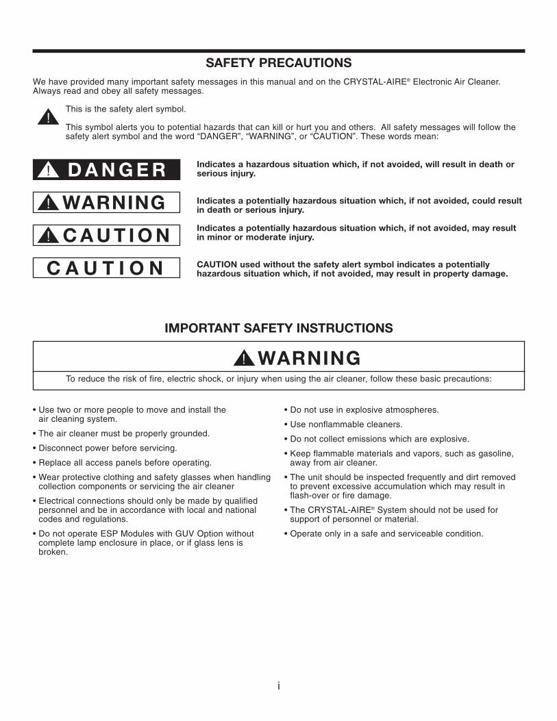
IMPORTANT SAFETY INSTRUCTIONS
To reduce the risk of fire, electric shock, or injury when using the air cleaner, follow these basic precautions:
SAFETY PRECAUTIONSWe have provided many important safety messages in this manual and on the CRYSTAL-AIRE® Electronic Air Cleaner.Always read and obey all safety messages.
• Use two or more people to move and install the air cleaning system.
• The air cleaner must be properly grounded.
• Disconnect power before servicing.
• Replace all access panels before operating.
• Wear protective clothing and safety glasses when handlingcollection components or servicing the air cleaner
• Electrical connections should only be made by qualifiedpersonnel and be in accordance with local and nationalcodes and regulations.
• Do not operate ESP Modules with GUV Option withoutcomplete lamp enclosure in place, or if glass lens isbroken.
• Do not use in explosive atmospheres.
• Use nonflammable cleaners.
• Do not collect emissions which are explosive.
• Keep flammable materials and vapors, such as gasoline,away from air cleaner.
• The unit should be inspected frequently and dirt removedto prevent excessive accumulation which may result inflash-over or fire damage.
• The CRYSTAL-AIRE® System should not be used forsupport of personnel or material.
• Operate only in a safe and serviceable condition.
!
! D A N G E R
! WARNING
! WARNING
! C A U T I O N
C A U T I O N
This is the safety alert symbol.
This symbol alerts you to potential hazards that can kill or hurt you and others. All safety messages will follow thesafety alert symbol and the word “DANGER”, “WARNING”, or “CAUTION”. These words mean:
Indicates a hazardous situation which, if not avoided, will result in death orserious injury.
Indicates a potentially hazardous situation which, if not avoided, could resultin death or serious injury.
Indicates a potentially hazardous situation which, if not avoided, may resultin minor or moderate injury.
CAUTION used without the safety alert symbol indicates a potentiallyhazardous situation which, if not avoided, may result in property damage.

1
Revised 12/06 Crystal-Aire®
Air Cleaner
INTRODUCTION
READ THIS MANUAL FIRSTThis manual contains important safety information. If you donot fully understand the instructions, consult your localCRYSTAL-AIRE® distributor or United Air Specialists beforeproceeding with installation or operation of the CRYSTAL-AIRE® system.
YOUR NEW AIR CLEANERNow you can breathe a lot easier. Your new air cleaner isthe most advanced product of its type on the market todayand will provide you with a safer, healthier environment. Asyou begin its operation, we would like you to know someimportant facts.
We appreciate your business. We have manufactured an aircleaner engineered to rigid specifications and quality controlchecks. A warranty backs every air cleaner that leaves ourfactory.
Like any piece of equipment, your air cleaner needsperiodic maintenance. Properly cared for, it will operate atpeak efficiency for many years.
While we hope you never have any problems, United AirSpecialists is always ready to lend assistance. We havefactory-trained distributors worldwide. Should you needinformation or service, contact your local CRYSTAL-AIRE®representative or the Customer Service Department atUnited Air Specialists, Inc.
INSTALLING YOUR CRYSTAL-AIRE®
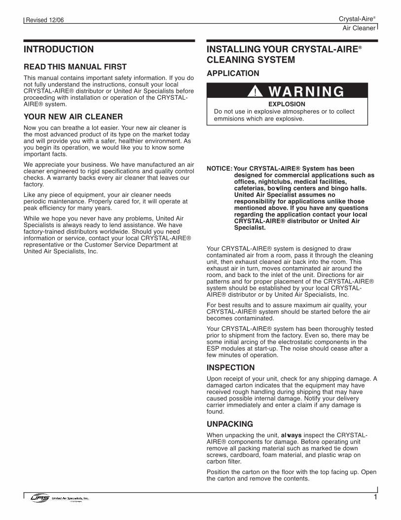
CLEANING SYSTEMAPPLICATION
NOTICE: Your CRYSTAL-AIRE® System has beendesigned for commercial applications such asoffices, nightclubs, medical facilities,cafeterias, bowling centers and bingo halls.United Air Specialist assumes noresponsibility for applications unlike thosementioned above. If you have any questionsregarding the application contact your localCRYSTAL-AIRE® distributor or United AirSpecialist.
Your CRYSTAL-AIRE® system is designed to drawcontaminated air from a room, pass it through the cleaningunit, then exhaust cleaned air back into the room. Thisexhaust air in turn, moves contaminated air around theroom, and back to the inlet of the unit. Directions for airpatterns and for proper placement of the CRYSTAL-AIRE®system should be established by your local CRYSTAL-AIRE® distributor or by United Air Specialists, Inc.
For best results and to assure maximum air quality, yourCRYSTAL-AIRE® system should be started before the airbecomes contaminated.
Your CRYSTAL-AIRE® system has been thoroughly testedprior to shipment from the factory. Even so, there may besome initial arcing of the electrostatic components in theESP modules at start-up. The noise should cease after afew minutes of operation.
INSPECTIONUpon receipt of your unit, check for any shipping damage. Adamaged carton indicates that the equipment may havereceived rough handling during shipping that may havecaused possible internal damage. Notify your deliverycarrier immediately and enter a claim if any damage isfound.
UNPACKINGWhen unpacking the unit, always inspect the CRYSTAL-AIRE® components for damage. Before operating unitremove all packing material such as marked tie downscrews, cardboard, foam material, and plastic wrap oncarbon filter.
Position the carton on the floor with the top facing up. Openthe carton and remove the contents.
! WARNINGEXPLOSION
Do not use in explosive atmospheres or to collectemmisions which are explosive.
When lifting the CRYSTAL-AIRE® unit, ensure liftingequipment does not damage electrical or mechanical partsfor the CRYSTAL-AIRE® unit.
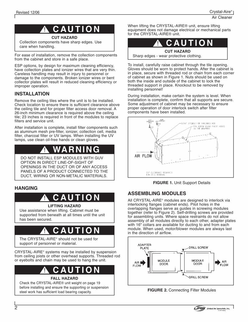
To install, carefully raise cabinet through the tile opening.Gloves should be worn to protect hands. After the cabinet isin place, secure with threaded rod or chain from each cornerof cabinet as shown in Figure 1. Nuts should be used onboth the inside and outside of the cabinet to lock thethreaded support in place. Knockout to be removed byinstalling personnel!
During installation, make certain the system is level. Wheninstallation is complete, confirm that all supports are secure.Some adjustment of cabinet may be necessary to ensureproper operation of door interlock switch after filtercomponents have been installed.
FIGURE 1. Unit Support Details
ASSEMBLING MODULESAll CRYSTAL-AIRE® modules are designed to interlock viainterlocking flanges (cabinet ends). Pilot holes in theoverlapping flanges serve as guides in screwing modulestogether (refer to Figure 2). Self-drilling screws are providedfor assembling units. Where space restraints do not allowassembly of all modules directly to each other, adapter plateswith 16" collars are available for ducting to and from eachmodule. When used, motor/blower modules are always lastin the direction of airflow.
FIGURE 2. Connecting Filter Modules
2
Revised 12/06 Crystal-Aire®
Air Cleaner
For ease of installation, remove the collection componentsfrom the cabinet and store in a safe place.
ESP options, by design for maximum cleaning efficiency,have collection plates and ionizer wires that are very thin.Careless handling may result in injury to personnel ordamage to the components. Broken ionizer wires or bentcollector plates will result in reduced cleaning efficiency orimproper operation.
INSTALLATIONRemove the ceiling tiles where the unit is to be installed.Check location to ensure there is sufficient clearance abovethe ceiling tile and for proper filter access door removal. A26-inch minimum clearance is required above the ceilingtile; 23 inches is required in front of the modules to replacefilters and service unit.
After installation is complete, install filter components suchas aluminum mesh pre-filter, ionizer, collection cell, mediafilter, charcoal filter or UV lamps. When installing the UVlamps, use clean oil-free hands or clean gloves.
HANGING
CRYSTAL-AIRE® systems may be installed by suspensionfrom ceiling joists or other overhead supports. Threaded rodor eyebolts and chain may be used to hang the unit.
! C AU T I O NCUT HAZARD
Collection components have sharp edges. Usecare when handling.
! C AU T I O NCUT HAZARD
Sharp edges - wear protective clothing.
! C AU T I O NLIFTING HAZARD
Use assistance when lifting. Cabinet must besupported from beneath at all times until the unithas been secured.
! C AU T I O NFALL HAZARD
Check the CRYSTAL-AIRE® unit weight on page 19before installing and ensure the supporting or suspensionsteel work has sufficient load bearing capacity.
! C AU T I O NThe CRYSTAL-AIRE® should not be used forsupport of personnel or material.
! WARNINGDO NOT INSTALL ESP MODULES WITH GUVOPTION IN DIRECT LINE-OF-SIGHT OFOPENINGS IN THE DUCT OR OF ANY ACCESSPANELS OF A PRODUCT CONNECTED TO THEDUCT, WIRING OR NON-METALIC MATERIALS.
3
Revised 12/06 Crystal-Aire®
Air Cleaner
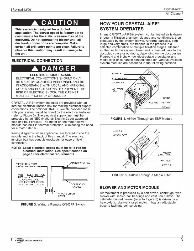
! C AU T I O NThis system is designed for a ductedapplication. The blower speed is factory set tocompensate for the static pressure loss of theductwork. Do not operate the blower until allductwork connections are complete. Makecertain all grill entry points are clear. Failure toobserve this caution may result in damage tothe unit.
ELECTRICAL CONNECTION
CRYSTAL-AIRE® system modules are provided with aninternal electrical junction box for making electrical supplyconnections. The optional ON/OFF switch, provided loosewith your system, must be wired by the electrical installer(refer to Figure 3). The electrical supply line must beprotected by an NEC (National Electric Code) approvedfuse or circuit breaker. The motor on the motor/blowermodule has built-in thermal protection, eliminating the needfor a motor starter.
Wiring diagrams, when applicable, are located inside themodule and in the back of this manual. The electricaljunction box has conduit knockouts for ease of fieldconnection.
NOTE: Local electrical codes must be followed forelectrical installation. See specifications onpage 19 for electrical requirements.
FIGURE 3. Wiring a Remote ON/OFF Switch
! DA N G E RELECTRIC SHOCK HAZARD
ELECTRICAL CONNECTIONS SHOULD ONLYBE MADE BY QUALIFIED PERSONNEL AND BEIN ACCORDANCE WITH LOCAL AND NATIONALCODES AND REGULATIONS. TO PREVENT THERISK OF ELECTRIC SHOCK, THE CABINETMUST BE PROPERLY GROUNDED.
HOW YOUR CRYSTAL-AIRE®
SYSTEM OPERATESIn any CRYSTAL-AIRE® system, contaminated air is drawnthrough a filtration chamber, cleaned and conditioned, thenexhausted by the system blower. Airborne particles, bothlarge and very small, are trapped in the process in aselected combination of multiple filtration stages. Cleanedair then exits the system blower and is directed back to theoccupied space or outdoors, depending on the duct design.Figures 4 and 5 show how electrostatic precipitator andmedia filter units handle contaminated air. Various availablesystem modules are described in the following sections.
FIGURE 4. Airflow Through an ESP Module
FIGURE 5. Airflow Through a Media Filter
BLOWER AND MOTOR MODULEAir movement is produced by a belt-driven, centrifugal-typeblower with sealed ball bearings and cast iron pulleys. Thecabinet-mounted blower (refer to Figure 6) is driven by aheavy-duty, totally-enclosed motor. It has an adjustablebase to facilitate belt servicing.
4
Revised 12/06 Crystal-Aire®
Air Cleaner
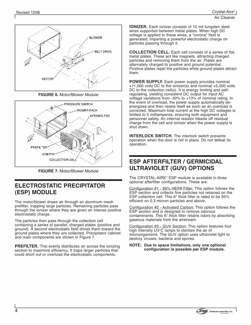
FIGURE 6. Motor/Blower Module
FIGURE 7. Motor/Blower Module
ELECTROSTATIC PRECIPITATOR(ESP) MODULE
The motor/blower draws air through an aluminum meshprefilter, trapping large particles. Remaining particles passthrough the ionizer where they are given an intense positiveelectrostatic charge.
The particles then pass through the collection cellcontaining a series of parallel, charged plates (positive andground). A second electrostatic field drives them toward theground plates where they are collected. Precipitator cabinetand main components are shown in Figure 7.
PREFILTER. This evenly distributes air across the ionizingsection to maximize efficiency. It traps larger particles thatcould short out or overload the electrostatic components.
IONIZER. Each ionizer consists of 10 mil tungsten steelwires supported between metal plates. When high DCvoltage is applied to these wires, a “corona” field isgenerated, imparting a powerful electrostatic charge onparticles passing through it.
COLLECTION CELL. Each cell consists of a series of flat,metal plates. These act like magnets, attracting chargedparticles and removing them from the air. Plates arealternately charged to positive and ground potential.Positive plates repel the particles while ground plates attractthem.
POWER SUPPLY. Each power supply provides nominal+11,000 volts DC to the ionizer(s) and nominal +5,500 voltsDC to the collection cell(s). It is energy limiting and self-regulating, yielding consistent DC output for input ACvoltage variations from -30% to +13% of nominal rating. Inthe event of overload, the power supply automatically de-energizes and then resets itself as soon as an overload iscorrected. Maximum total current at the high DC voltages islimited to 5 milliamperes, ensuring both equipment andpersonnel safety. An internal resistor bleeds off residualcharge from the cell and ionizer when the power supply isshut down.
INTERLOCK SWITCH. The interlock switch preventsoperation when the door is not in place. Do not defeat itsoperation.
ESP AFTERFILTER / GERMICIDALULTRAVIOLET (GUV) OPTIONS
The CRYSTAL-AIRE® ESP module is available in threeoptional afterfilter configurations. These are:
Configuration #1 - 95% HEPA Filter: This option follows theESP section and collects fine particles not retained on theESP collection cell. This 6" thick filter is rated to be 95%efficient on 0.3 micron particles and above.
Configuration #2 - Activated Carbon: This option follows theESP section and is designed to remove odorouscontaminants. This 6" thick filter retains odors by absorbinggaseous materials from the airstream.
Configuration #3 - GUV Section: This option features fourhigh intensity UV-C lamps to sterilize the air ofmicroorganisms. The GUV option uses ultraviolet light todestroy viruses, bacteria and spores.
NOTE: Due to space limitations, only one optionalconfiguration is possible per ESP module.
5
Revised 12/06 Crystal-Aire®
Air Cleaner
BAG FILTER MODULE
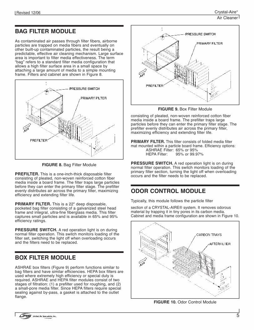
As contaminated air passes through filter fibers, airborneparticles are trapped on media fibers and eventually onother built-up contaminated particles, the result being apredictable, effective air cleaning mechanism. Large surfacearea is important to filter media effectiveness. The term“bag” refers to a standard filter media configuration thatallows a high filter surface area in a small space byattaching a large amount of media to a simple mountingframe. Filters and cabinet are shown in Figure 8.
FIGURE 8. Bag Filter Module
PREFILTER. This is a one-inch-thick disposable filterconsisting of pleated, non-woven reinforced cotton fibermedia inside a board frame. The filter traps large particlesbefore they can enter the primary filter stage. The prefilterevenly distributes air across the primary filter, maximizingefficiency and extending filter life.
PRIMARY FILTER. This is a 22" deep disposable,pocketed bag filter consisting of a galvanized steel headframe and integral, ultra-fine fiberglass media. This filtercaptures small particles and is available in 65% and 95%efficiency ratings.
PRESSURE SWITCH. A red operation light is on duringnormal filter operation. This switch monitors loading of thefilter set, switching the light off when overloading occursand the filters need to be replaced.
BOX FILTER MODULE
ASHRAE box filters (Figure 9) perform functions similar tobag filters and have similar efficiencies. HEPA box filters areused where extremely high efficiency or special duty isrequired. ASHRAE and HEPA filter modules consist of twostages of filtration: (1) a prefilter used for roughing, and (2)a small-pore media filter. Since HEPA filters require specialsealing against by-pass, a gasket is attached to the outletflange.
FIGURE 9. Box Filter Module
consisting of pleated, non-woven reinforced cotton fibermedia inside a board frame. The prefilter traps largeparticles before they can enter the primary filter stage. Theprefilter evenly distributes air across the primary filter,maximizing efficiency and extending filter life.
PRIMARY FILTER. This filter consists of folded media filtermat mounted within a particle board frame. Efficiency options:
ASHRAE Filter: 65% or 95%HEPA Filter: 95% or 99.97%
PRESSURE SWITCH. A red operation light is on duringnormal filter operation. This switch monitors loading of theprimary filter section, turning the light off when overloadingoccurs and the filter needs to be replaced.
ODOR CONTROL MODULE
Typically, this module follows the particle filter
section of a CRYSTAL-AIRE® system. It removes odorousmaterial by trapping it in tiny pores in its carbon media.Cabinet and media frame configuration are shown in Figure 10.
FIGURE 10. Odor Control Module
6
Revised 12/06 Crystal-Aire®
Air Cleaner
CARBON TRAYS. These trays hold large quantities ofspecial, highly-porous carbon, arranged in 6 one-inch-thicktrays in a vee-bank configuration. The large area that facesthe air stream allows the carbon trays to absorb gaseouscontaminants from the passing low-velocity airstream. Eachmodule holds 20 pounds of carbon. Where the applicationrequires, trays filled with potassium permanganate are alsoavailable.
AFTERFILTER. This is a one-inch-deep disposable mediafilter used to capture any carbon dust which might beentrained into the airstream.
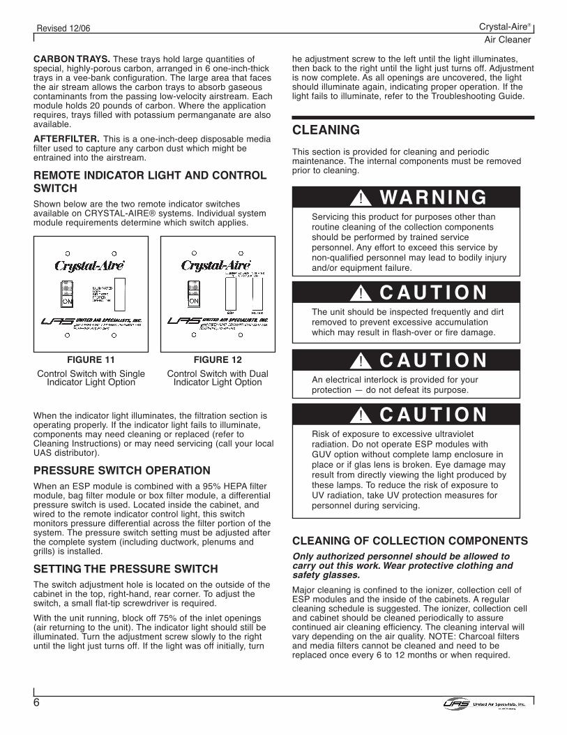
REMOTE INDICATOR LIGHT AND CONTROLSWITCHShown below are the two remote indicator switchesavailable on CRYSTAL-AIRE® systems. Individual systemmodule requirements determine which switch applies.
When the indicator light illuminates, the filtration section isoperating properly. If the indicator light fails to illuminate,components may need cleaning or replaced (refer toCleaning Instructions) or may need servicing (call your localUAS distributor).
PRESSURE SWITCH OPERATIONWhen an ESP module is combined with a 95% HEPA filtermodule, bag filter module or box filter module, a differentialpressure switch is used. Located inside the cabinet, andwired to the remote indicator control light, this switchmonitors pressure differential across the filter portion of thesystem. The pressure switch setting must be adjusted afterthe complete system (including ductwork, plenums andgrills) is installed.
SETTING THE PRESSURE SWITCHThe switch adjustment hole is located on the outside of thecabinet in the top, right-hand, rear corner. To adjust theswitch, a small flat-tip screwdriver is required.
With the unit running, block off 75% of the inlet openings(air returning to the unit). The indicator light should still beilluminated. Turn the adjustment screw slowly to the rightuntil the light just turns off. If the light was off initially, turn
he adjustment screw to the left until the light illuminates,then back to the right until the light just turns off. Adjustmentis now complete. As all openings are uncovered, the lightshould illuminate again, indicating proper operation. If thelight fails to illuminate, refer to the Troubleshooting Guide.
CLEANING
This section is provided for cleaning and periodicmaintenance. The internal components must be removedprior to cleaning.
CLEANING OF COLLECTION COMPONENTSOnly authorized personnel should be allowed tocarry out this work. Wear protective clothing andsafety glasses.
Major cleaning is confined to the ionizer, collection cell ofESP modules and the inside of the cabinets. A regularcleaning schedule is suggested. The ionizer, collection celland cabinet should be cleaned periodically to assurecontinued air cleaning efficiency. The cleaning interval willvary depending on the air quality. NOTE: Charcoal filtersand media filters cannot be cleaned and need to bereplaced once every 6 to 12 months or when required.
FIGURE 11
Control Switch with SingleIndicator Light Option
FIGURE 12
Control Switch with DualIndicator Light Option
! WARNINGServicing this product for purposes other thanroutine cleaning of the collection componentsshould be performed by trained servicepersonnel. Any effort to exceed this service bynon-qualified personnel may lead to bodily injuryand/or equipment failure.
! C AU T I O NThe unit should be inspected frequently and dirtremoved to prevent excessive accumulationwhich may result in flash-over or fire damage.
! C AU T I O NAn electrical interlock is provided for yourprotection — do not defeat its purpose.
! C AU T I O NRisk of exposure to excessive ultravioletradiation. Do not operate ESP modules withGUV option without complete lamp enclosure inplace or if glas lens is broken. Eye damage mayresult from directly viewing the light produced bythese lamps. To reduce the risk of exposure toUV radiation, take UV protection measures forpersonnel during servicing.
7
Revised 12/06 Crystal-Aire®
Air Cleaner
Procedures for cleaning ESP modules are as follows:
1. Switch off/Isolate the electrical supply to theCRYSTAL-AIRE® unit. Lock isolator in off position.
2. Wait 15 seconds for the high voltage charge on theunicell to bleed off before removing the componentaccess door. For added safety, manually discharge theunicell (See Discharging High-Voltage Componentssection on page 12).
3. Remove aluminum mesh prefilter.
4. Remove ionizer and collection cell from cabinet.
5. Remove charcoal or media filters if supplied.
6. Clean components by soaking in hot detergent solutionfor a minimum of 30 minutes. The cleaning solutiontemperature should not exceed 150°F. Agitate orspray components in the hot solution to removeloosened dirt. Any cleaner used must be inhibited forthe protection of aluminum filters and cells. UAS offersan exclusive detergent which can be purchased throughUAS or your local distributor.
NOTE: To prevent excessive deterioration ofcomponents, do not soak for more than 1 hour.
7. Immediately after removing components from thedetergent bath, flush away any remaining residue andrinse thoroughly with warm water. Shake off excesswater.
8. Ionizer and cell insulators may require additionalcleaning by hand.
9. Set collection cells, ionizers and mesh filters in a warmroom, with plates standing vertically, until allcomponents have completely drained and air dry to thetouch. Thirty to sixty minutes is normally satisfactory.
10. Vacuum clean the interior of the cabinet and clean offall electrical connections before reinstalling thecomponents.
11. Carefully clean UV lamps, if supplied, with a glasscleaner. Avoid handling with dirty or oily hands or dirtygloves.
12. Reinstall aluminum mesh filter, ionizer, collection celland new charcoal filter or media filters.
13. Install and secure filter access door.
14. Switch on the CRYSTAL-AIRE® unit and check that theindicator light is illuminated.
15. If the indicator lamp flickers or does not come on at all,the collection cell may not be thoroughly dry. Airpassing through the unit will dry out the unicell and thelamp should turn on in a few minutes.
WHEN ARE COMPONENTS CLEAN?After cleaning, collection components should have a clean,not necessarily “new”, aluminum appearance. Slightdiscoloration will not affect system efficiency. Here is achecklist for acceptable components:
Ionizer
1. Aluminum frame and plates are free of contaminantbuildup.
2. Ceramic insulators are clean and white (no residualcoating). Cracked or carbon-tracked insulators havebeen replaced.
3. Wires and springs are intact and taut, centeredbetween plates and free of coatings.
4. Contact springs and contact screws are properlyaligned.
5. Bent or broken parts have been repaired or replaced.
Collection Cell Plates
1. Aluminum frame is square, plates are parallel and hotplates are centered between ground plates.
2. Residual particulate has been removed between platesand at corner supports. Material bridging across plateshas been removed.
3. Insulators are free of contaminant. Carbon-trackedinsulators have been repaired or replaced.
4. Contact springs and contact screws are properlyaligned.
5. Bent or broken plates have been repaired or replaced.
Prefilters
1. Aluminum media and frame are free of contaminant.
2. Frame is square and media is intact.
3. Filters are always installed with drain holes down andarrow on their frames pointing in the direction of airflow.
UV Lamps
1. Glass is clean and bright.
Cabinet
1. Interior is free of dirt buildup.
2. Motor/blower has been checked for heavy buildup, andcleaned if required.
! C AU T I O NWhen disposing of collected pollutants, complywith local and national codes.
8
Revised 12/06 Crystal-Aire®
Air Cleaner
MAINTENANCE AND SERVICEThis section is for the use of trained servicepersonnel only.
Due to the simplicity of the design, breakdowns arerestricted to these components:
• motor/blower• power supply• ionizer• collection cell• blower control switch• indicator light
MOTOR/BLOWER MODULE
Maintenance of the motor/blower compartment is generallylimited to periodically vacuuming the cabinet interior andremoving any built-up material which may have collected.Motors have permanently-lubricated bearings so no furtherbearing lube is required.
MEASURING MOTOR CURRENT
NOTE: Measure current at the fused disconnect ormain power switch. Erroneous readings mayresult if measurements are made in thevicinity of the high-voltage power supplylocated in the ESP Module.
To measure the amperage draw of the motor, use an AmpProbe. Amperage should not exceed the FLA (full load amp)rating stamped on the motor nameplate. If amperage isexcessive, check:
1. All access panels are securely attached.2. All duct work is attached.3. The drive belt for excessive tightness. Loosen as required.
CHECKING BELTS
Motor/blower drive belts are preset at the factory for propertension based on specified airflow parameters. They dorequire periodic checkout and adjustment to assure longservice life. The following should be checked at leastmonthly.
1. Belt tension. One-half inch deflection at the midpointbetween pulleys indicates correct tension. Adjust asnecessary.
2. Belt wear. Frayed edges and stress cracks in belt wallssignal belt wear. Replace as required.
3. Unit noise. Higher than normal noise indicatesabnormal belt or bearing wear. Where motor bearingsare regreasable, lubricate yearly. Where motor bearingsare not regreasable (bearings are sealed), excessivenoise may indicate that the bearings need to bereplaced.
AIRFLOW ADJUSTMENT
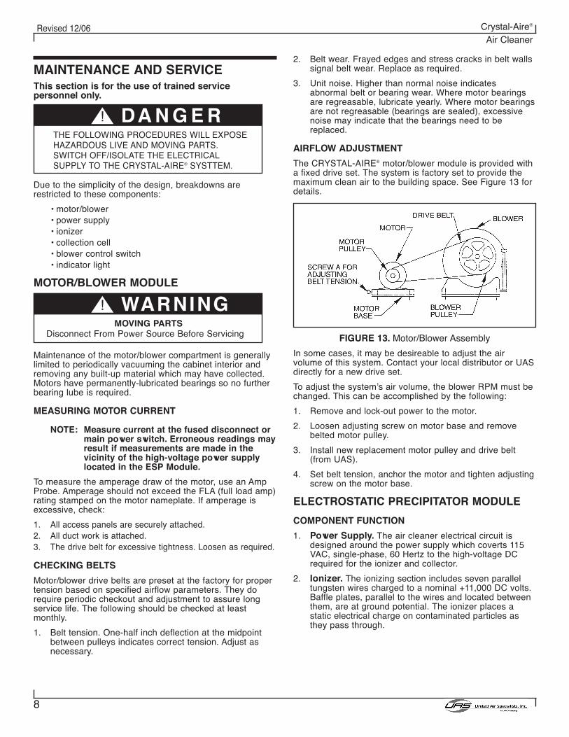
The CRYSTAL-AIRE® motor/blower module is provided witha fixed drive set. The system is factory set to provide themaximum clean air to the building space. See Figure 13 fordetails.
FIGURE 13. Motor/Blower Assembly
In some cases, it may be desireable to adjust the airvolume of this system. Contact your local distributor or UASdirectly for a new drive set.
To adjust the system’s air volume, the blower RPM must bechanged. This can be accomplished by the following:
1. Remove and lock-out power to the motor.
2. Loosen adjusting screw on motor base and removebelted motor pulley.
3. Install new replacement motor pulley and drive belt(from UAS).
4. Set belt tension, anchor the motor and tighten adjustingscrew on the motor base.
ELECTROSTATIC PRECIPITATOR MODULE
COMPONENT FUNCTION
1. Power Supply. The air cleaner electrical circuit isdesigned around the power supply which coverts 115VAC, single-phase, 60 Hertz to the high-voltage DCrequired for the ionizer and collector.
2. Ionizer. The ionizing section includes seven paralleltungsten wires charged to a nominal +11,000 DC volts.Baffle plates, parallel to the wires and located betweenthem, are at ground potential. The ionizer places astatic electrical charge on contaminated particles asthey pass through.
! DA N G E RTHE FOLLOWING PROCEDURES WILL EXPOSEHAZARDOUS LIVE AND MOVING PARTS.SWITCH OFF/ISOLATE THE ELECTRICALSUPPLY TO THE CRYSTAL-AIRE® SYSTTEM.
! WARNINGMOVING PARTS
Disconnect From Power Source Before Servicing
9
Revised 12/06 Crystal-Aire®
Air Cleaner
3. Collection Cell. The collecting section consists of aseries of parallel plates alternately charged to +5,500DC volts and ground. The field between positive andground plates forces positive-charged particles to theground plates, removing them from the airstream.
TOOLS REQUIRED FOR TROUBLESHOOTING ESPMODULE
1. Screwdriver — common type, 8" or longer, with aninsulated handle.
2. Volt-Ohm Meter — for measuring AC voltage (0 to 500VAC), circuit continuity (0 to ∞ ohms), and low DCvoltage (0 to 100 VDC).
3. High Voltage DC Probe — positive polarity, to measurehigh-voltage DC power supply (minimum range: 0 to 15KVDC).
4. Protective clothing and safety glasses.
SETTING UP TO MEASURE HIGH VOLTAGE
Before performing any tests, proceed as follows.
1. Turn the unit off and disconnect from power source.
2. Open access door.
3. Models with GUV lamps — to reduce the risk ofexposure to UV radiation, take UV protection measuresduring servicing.
4. Connect the ground clip of the high-voltage probe to thecabinet side or any convenient ground point (e.g., agrounded collection component). Make certain theconnection point is a solid ground point.
5. Defeat electrical interlock switch.
6. Turn on the unit control switch.
! DA N G E RRISK OF ELECTRIC SHOCK. UV LIGHT SOURCE.
! C AU T I O NUV LIGHT SOURCE
Risk of exposure to ultraviolet radiation. Eyedamage may result from directly viewing the lightfrom UV lamps.
! C AU T I O NELECTROSTATIC SHOCK HAZARD
Make certain to use caution and turn switch offafter measuring voltages below.
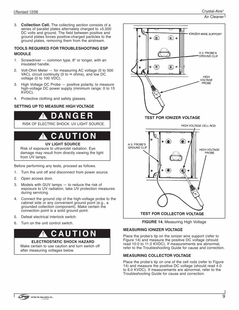
FIGURE 14. Measuring High Voltage
MEASURING IONIZER VOLTAGE
Place the probe’s tip on the ionizer wire support (refer toFigure 14) and measure the positive DC voltage (shouldread 10.0 to 11.0 KVDC). If measurements are abnormal,refer to the Troubleshooting Guide for cause and correction.
MEASURING COLLECTOR VOLTAGE
Place the probe’s tip on one of the cell rods (refer to Figure14) and measure the positive DC voltage (should read 4.0to 6.0 KVDC). If measurements are abnormal, refer to theTroubleshooting Guide for cause and correction.
10
Revised 12/06 Crystal-Aire®
Air Cleaner
FIGURE 15. Measuring Power Pack Output Voltage
CHECKING POWER SUPPLY HIGH-VOLTAGEOUTPUTTo measure the output from the ionizer and collection cellterminals of the power supply:
1. Remove the prefilter, ionizer and collection cell from thecabinet.
2. Turn the module control switch on.
3. With caution defeat electrical interlock switch.
FIGURE 16. Standard Power Supply Showing Connecting Points.
4. Connect the probe ground clip to a convenient cabinetground point (refer to Figure 15).
5. Place probe’s tip on the ionizer high-voltage contact(should read 11.0 to 12.0 KVDC).
6. Place probe’s tip on the collection cell high-voltagecontact (should read 5.5 to 6.0 KVDC).
CHECKING LAMP TERMINAL OUTPUT
Connect a good neon lamp to terminal “LIGHT” and toterminal “GND” or cabinet ground. If lamps does not light,replace power supply. If lamp lights, check wiring and unitindicator lamp.
IONIZER WIRESShould an ionizer wire be broken or missing, it must bereplaced immediately to avoid uncharged particles passingthrough the CRYSTAL-AIRE® unit and being dischargedinto the workplace.
Loss of high voltage in the ionizer can occur if the ionizerwires and the ionizer insulators are not cleaned thoroughly,or the ionizer high-voltage spring contacts are not in placeor not making contact.
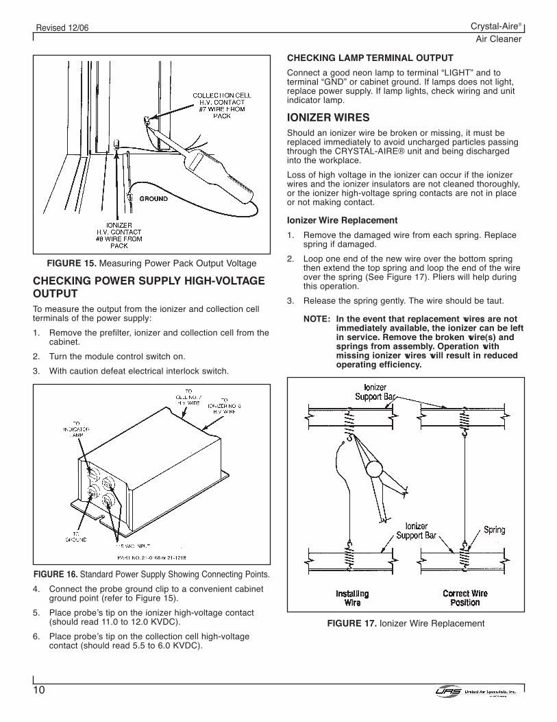
Ionizer Wire Replacement
1. Remove the damaged wire from each spring. Replacespring if damaged.
2. Loop one end of the new wire over the bottom springthen extend the top spring and loop the end of the wireover the spring (See Figure 17). Pliers will help duringthis operation.
3. Release the spring gently. The wire should be taut.
NOTE: In the event that replacement wires are notimmediately available, the ionizer can be leftin service. Remove the broken wire(s) andsprings from assembly. Operation withmissing ionizer wires will result in reducedoperating efficiency.
FIGURE 17. Ionizer Wire Replacement
11
Revised 12/06 Crystal-Aire®
Air Cleaner
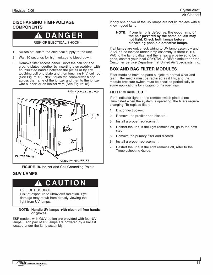
DISCHARGING HIGH-VOLTAGECOMPONENTS
1. Switch off/Isolate the electrical supply to the unit.
2. Wait 30 seconds for high voltage to bleed down.
3. Remove filter access panel. Short the cell hot andground plates together by inserting a screwdriver withan insulated handle between the plates or by firsttouching cell end plate and then touching H.V. cell rod.(See Figure 18). Next, touch the screwdriver bladeacross the frame of the ionizer and then to the ionizerwire support or an ionizer wire (See Figure 18).
FIGURE 18. Ionizer and Cell Grounding Points
GUV LAMPS
NOTE: Handle UV lamps with clean oil free handsor gloves.
ESP models with GUV option are provided with four UVlamps. Each pair of UV lamps are powered by a ballastlocated under the lamp assembly.
! DA N G E RRISK OF ELECTICAL SHOCK.
! C AU T I O NUV LIGHT SOURCERisk of exposure to ultraviolet radiation. Eyedamage may result from directly viewing thelight from UV lamps.
If only one or two of the UV lamps are not lit, replace with aknown good lamp.
NOTE: If one lamp is defective, the good lamp ofthe pair powered by the same ballast maynot light. Check both lamps beforediscarding possible defective lamps.
If all lamps are out, check wiring to UV lamp assembly and2 AMP fuse located under lamp assembly. If there is 120VAC to the lamp ballast and the lamps are believed to begood, contact your local CRYSTAL-AIRE® distributor or theCustomer Service Department at United Air Specialists, Inc.
BOX AND BAG FILTER MODULESFilter modules have no parts subject to normal wear andtear. Filter media must be replaced as it fills, and themodule pressure switch must be checked periodically insome applications for clogging of its openings.
FILTER CHANGEOUT
If the indicator light on the remote switch plate is notilluminated when the system is operating, the filters requirechanging. To replace filters:
1. Disconnect power.
2. Remove the prefilter and discard.
3. Install a proper replacement.
4. Restart the unit. If the light remains off, go to the nextstep.
5. Remove the primary filter and discard.
6. Install a proper replacement.
7. Restart the unit. If the light remains off, refer to theTroubleshooting Guide.
12
Revised 12/06 Crystal-Aire®
Air Cleaner
PROBLEM POSSIBLE CAUSE CORRECTIVE ACTION*
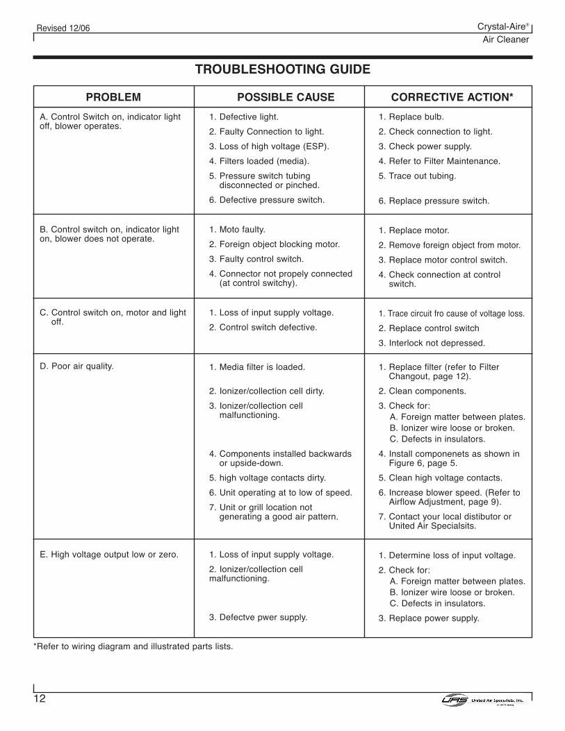
TROUBLESHOOTING GUIDE
A. Control Switch on, indicator lightoff, blower operates.
B. Control switch on, indicator lighton, blower does not operate.
C. Control switch on, motor and lightoff.
D. Poor air quality.
E. High voltage output low or zero.
1. Defective light.
2. Faulty Connection to light.
3. Loss of high voltage (ESP).
4. Filters loaded (media).
5. Pressure switch tubingdisconnected or pinched.
6. Defective pressure switch.
1. Moto faulty.
2. Foreign object blocking motor.
3. Faulty control switch.
4. Connector not propely connected(at control switchy).
1. Loss of input supply voltage.
2. Control switch defective.
1. Media filter is loaded.
2. Ionizer/collection cell dirty.
3. Ionizer/collection cellmalfunctioning.
4. Components installed backwardsor upside-down.
5. high voltage contacts dirty.
6. Unit operating at to low of speed.
7. Unit or grill location notgenerating a good air pattern.
1. Loss of input supply voltage.
2. Ionizer/collection cellmalfunctioning.
3. Defectve pwer supply.
1. Replace bulb.
2. Check connection to light.
3. Check power supply.
4. Refer to Filter Maintenance.
5. Trace out tubing.
6. Replace pressure switch.
1. Replace motor.
2. Remove foreign object from motor.
3. Replace motor control switch.
4. Check connection at controlswitch.
1. Trace circuit fro cause of voltage loss.
2. Replace control switch
3. Interlock not depressed.
1. Replace filter (refer to FilterChangout, page 12).
2. Clean components.
3. Check for:A. Foreign matter between plates.B. Ionizer wire loose or broken.C. Defects in insulators.
4. Install componenets as shown inFigure 6, page 5.
5. Clean high voltage contacts.
6. Increase blower speed. (Refer toAirflow Adjustment, page 9).
7. Contact your local distibutor orUnited Air Specialsits.
1. Determine loss of input voltage.
2. Check for:A. Foreign matter between plates.B. Ionizer wire loose or broken.C. Defects in insulators.
3. Replace power supply.
*Refer to wiring diagram and illustrated parts lists.
13
Revised 12/06 Crystal-Aire®
Air Cleaner
PARTS ORDERINGTo order parts, contact your local distributor or UAS directly:
United Air Specialists, Inc.4440 Creek Road
Cincinnati, Ohio 45242Attn: Customer Service Department
1-800-252-4647www.uasinc.com
The following information is required for prompt service:
1. Unit Model Number (inside access door).
2. Unit Serial Number (inside access door).
3. Part Number (refer to Illustrated Parts breakdown).
When returning a defective part under warranty, you mustcall UAS for a return authorization number (RMA). Thisnumber should appear on the package being returned. Withthis control number, we can ensure prompt service. You canalso return defective parts to your local distributor.
14
Revised 12/06 Crystal-Aire®
Air Cleaner
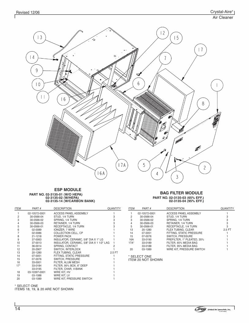
ESP MODULEPART NO. 02-3135-01 (W/O HEPA)
02-3135-02 (W/HEPA)02-3135-14 (W/CARBON BANK)
ITEM PART # DESCRIPTION QUANTITY
1 02-10572-0001 ACCESS PANEL ASSEMBLY 12 30-0566-04 STUD, 1/4 TURN 33 30-0566-02 SPRING, 1/4 TURN 34 30-0566-03 RETAINER, 1/4 TURN 35 30-0566-01 RECEPTACLE, 1/4 TURN 36 02-0089 IONIZER, 7 WIRE 17 02-0086 COLLECTION CELL, CP 18 21-1218 POWER PACK 19 37-0063 INSULATOR, CERAMIC, 5/8" DIA X 1" LG 1
10 37-0013 INSULATOR, CERAMIC, 5/8" DIA X 1 1/2" LAG 111 36-0014 SPRING, CONTACT 212 20-2907 SWITCH, INTERLOCK 113 20-1280 FLEX TUBING, CLEAR 2.5 FT14 07-0051 FITTING, STATIC PRESSURE 115 07-0076 SWITCH, PRESSURE 116 33-0001 FILTER, ALUM MESH 117* 33-0184 FILTER, 95% BOX, 6" DEEP 1
33-0195 FILTER, CHAR, V-BANK 118 03-10397-0001 WIRE KIT, HV 119 03-1088 WIRE KIT, LV 120 03-1089 WIRE KIT, PRESSURE SWITCH 1
* SELECT ONEITEMS 18, 19, & 20 ARE NOT SHOWN
BAG FILTER MODULEPART NO. 02-3135-03 (65% EFF.)
02-3135-04 (95% EFF.)
ITEM PART # DESCRIPTION QUANTITY
1 02-10572-0001 ACCESS PANEL ASSEMBLY 12 30-0566-04 STUD, 1/4 TURN 33 30-0566-02 SPRING, 1/4 TURN 34 30-0566-03 RETAINER, 1/4 TURN 35 30-0566-01 RECEPTACLE, 1/4 TURN 3
13 20-1280 FLEX TUBING, CLEAR 2.5 FT14 07-0051 FITTING, STATIC PRESSURE 115 07-0076 SWITCH, PRESSURE 1
16A 33-0190 PREFILTER, 1" PLEATED, 35% 117A* 33-0189 FILTER, 65% MEDIA BAG 1
33-0188 FILTER, 95% MEDIA BAG 120 03-1089 WIRE KIT, PRESSURE SWITCH 1
* SELECT ONEITEM 20 NOT SHOWN
15
Revised 12/06 Crystal-Aire®
Air Cleaner
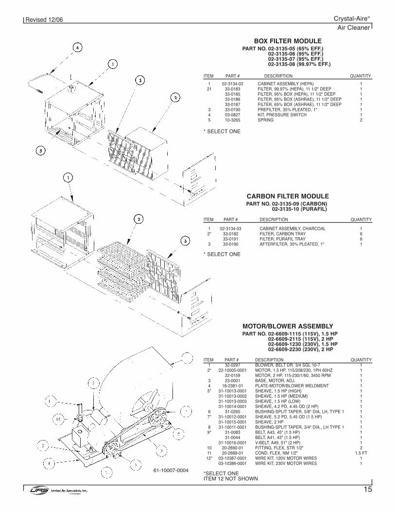
BOX FILTER MODULEPART NO. 02-3135-05 (65% EFF.)
02-3135-06 (95% EFF.)02-3135-07 (95% EFF.)02-3135-08 (99.97% EFF.)
ITEM PART # DESCRIPTION QUANTITY
1 02-3134-02 CABINET ASSEMBLY (HEPA) 121 33-0183 FILTER, 99.97% (HEPA), 11 1/2" DEEP 1
33-0185 FILTER, 95% BOX (HEPA), 11 1/2" DEEP 133-0186 FILTER, 95% BOX (ASHRAE), 11 1/2" DEEP 133-0187 FILTER, 65% BOX (ASHRAE), 11 1/2" DEEP 1
3 33-0190 PREFILTER, 35% PLEATED, 1" 14 03-0827 KIT, PRESSURE SWITCH 15 10-3265 SPRING 2
* SELECT ONE
MOTOR/BLOWER ASSEMBLYPART NO. 02-6609-1115 (115V), 1.5 HP
02-6609-2115 (115V), 2 HP02-6609-1230 (230V), 1.5 HP02-6609-2230 (230V), 2 HP
ITEM PART # DESCRIPTION QUANTITY1 32-0297 BLOWER, BELT DR. 3/4 SGL 10-7 12* 22-10005-0001 MOTOR, 1.5 HP, 115/208/230, 1PH 60HZ 1
22-0159 MOTOR, 2 HP, 115-230/1/60, 3450 RPM 13 23-0001 BASE, MOTOR, ADJ. 14 18-2381-01 PLATE-MOTOR/BLOWER WELDMENT 15* 31-10013-0001 SHEAVE, 1.5 HP (HIGH) 1
31-10013-0002 SHEAVE, 1.5 HP (MEDIUM) 131-10013-0003 SHEAVE, 1.5 HP (LOW) 131-10014-0001 SHEAVE, 4.2 PD, 4.45 OD (2 HP) 1
6 31-0265 BUSHING-SPLIT TAPER, 5/8" DIA, LH, TYPE 1 17* 31-10012-0001 SHEAVE, 5.2 PD, 5.45 OD (1.5 HP) 1
31-10015-0001 SHEAVE, 2 HP 18 31-10011-0001 BUSHING-SPLIT TAPER, 3/4" DIA., LH TYPE 1 19* 31-0083 BELT, A43, 45" (1.5 HP) 1
31-0044 BELT, A41, 43" (1.5 HP) 131-10016-0001 V-BELT, A49, 51" (2 HP) 1
10 20-2690-01 FITTING, FLEX, STR 1/2" 211 20-2689-01 COND. FLEX, NM 1/2" 1.5 FT12* 03-10387-0001 WIRE KIT, 120V MOTOR WIRES 1
03-10386-0001 WIRE KIT, 230V MOTOR WIRES 1
*SELECT ONEITEM 12 NOT SHOWN
CARBON FILTER MODULEPART NO. 02-3135-09 (CARBON)
02-3135-10 (PURAFIL)
ITEM PART # DESCRIPTION QUANTITY
1 02-3134-03 CABINET ASSEMBLY, CHARCOAL 12* 33-0182 FILTER, CARBON TRAY 6
33-0191 FILTER, PURAFIL TRAY 63 33-0190 AFTERFILTER, 35% PLEATED, 1" 1
* SELECT ONE
61-10007-0004
16
Revised 12/06 Crystal-Aire®
Air Cleaner
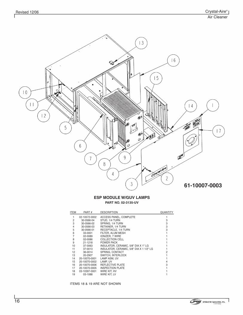
ESP MODULE W/GUV LAMPSPART NO. 02-3135-UV
ITEM PART # DESCRIPTION QUANTITY
1 02-10572-0002 ACCESS PANEL, COMPLETE 12 30-0566-04 STUD, 1/4 TURN 33 30-0566-02 SPRING, 1/4 TURN 34 30-0566-03 RETAINER, 1/4 TURN 35 30-0566-01 RECEPTACLE, 1/4 TURN 36 33-0001 FILTER, ALUM MESH 17 02-0089 IONIZER, 7 WIRE 18 02-0086 COLLECTION CELL 19 21-1218 POWER PACK 1
10 37-0063 INSULATOR, CERAMIC, 5/8" DIA X 1" LG 111 37-0013 INSULATOR, CERAMIC, 5/8" DIA X 1 1/2" LG 112 36-0014 SPRING, CONTACT 213 20-2907 SWITCH, INTERLOCK 114 20-10070-0001 LAMP ASM, UV 115 20-10070-0002 LAMP, UV 416 20-10070-0006 REFLECTIVE PLATE 317 20-10070-0005 INSPECTION PLATE 118 03-10397-0001 WIRE KIT, HV 119 03-1088 WIRE KIT, LV 1
ITEMS 18 & 19 ARE NOT SHOWN
61-10007-0003
17
Revised 12/06 Crystal-Aire®
Air Cleaner
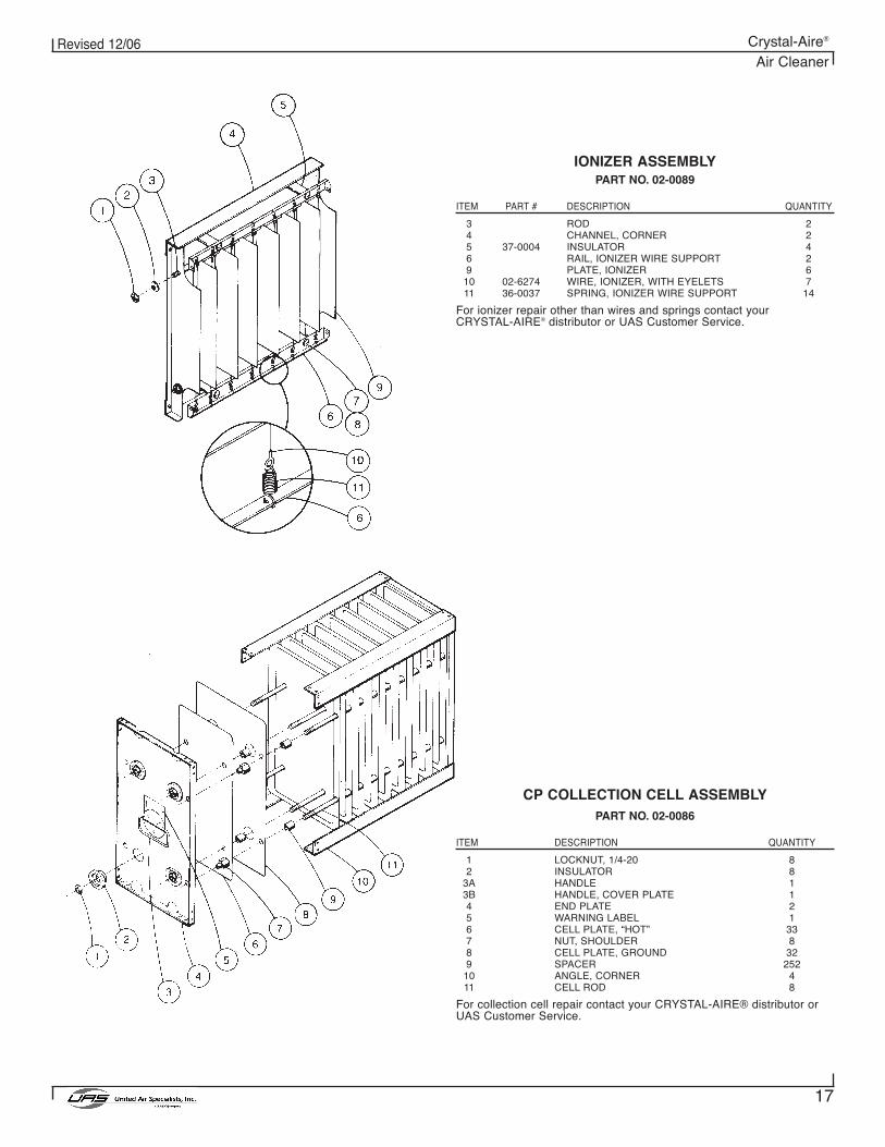
IONIZER ASSEMBLYPART NO. 02-0089
ITEM PART # DESCRIPTION QUANTITY
3 ROD 24 CHANNEL, CORNER 25 37-0004 INSULATOR 46 RAIL, IONIZER WIRE SUPPORT 29 PLATE, IONIZER 6
10 02-6274 WIRE, IONIZER, WITH EYELETS 711 36-0037 SPRING, IONIZER WIRE SUPPORT 14
For ionizer repair other than wires and springs contact your CRYSTAL-AIRE® distributor or UAS Customer Service.
CP COLLECTION CELL ASSEMBLYPART NO. 02-0086
ITEM DESCRIPTION QUANTITY
1 LOCKNUT, 1/4-20 82 INSULATOR 8
3A HANDLE 13B HANDLE, COVER PLATE 14 END PLATE 25 WARNING LABEL 16 CELL PLATE, “HOT” 337 NUT, SHOULDER 88 CELL PLATE, GROUND 329 SPACER 252
10 ANGLE, CORNER 411 CELL ROD 8
For collection cell repair contact your CRYSTAL-AIRE® distributor orUAS Customer Service.
18
Revised 12/06 Crystal-Aire®
Air Cleaner
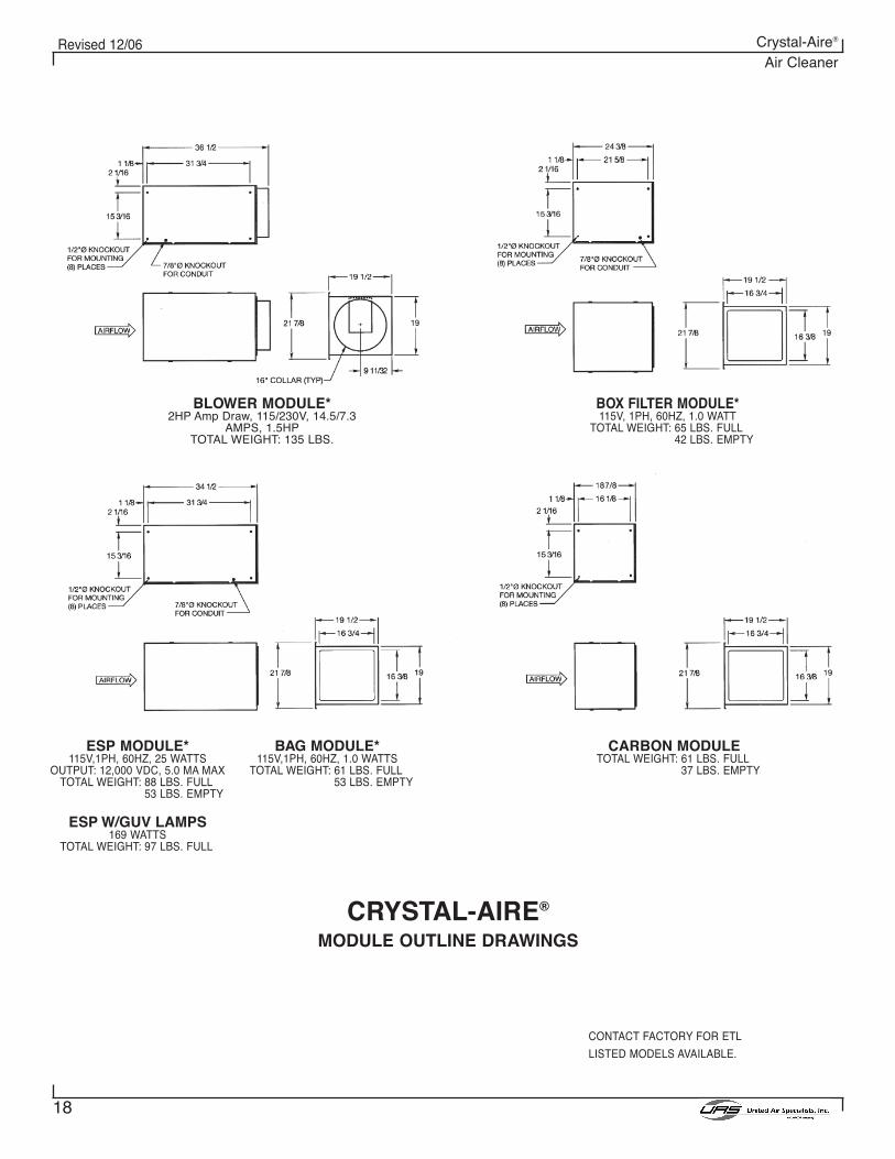
BLOWER MODULE*2HP Amp Draw, 115/230V, 14.5/7.3
AMPS, 1.5HPTOTAL WEIGHT: 135 LBS.
ESP MODULE*115V,1PH, 60HZ, 25 WATTS
OUTPUT: 12,000 VDC, 5.0 MA MAXTOTAL WEIGHT: 88 LBS. FULL
53 LBS. EMPTY
ESP W/GUV LAMPS169 WATTS
TOTAL WEIGHT: 97 LBS. FULL
BAG MODULE*115V,1PH, 60HZ, 1.0 WATTS
TOTAL WEIGHT: 61 LBS. FULL53 LBS. EMPTY
CARBON MODULETOTAL WEIGHT: 61 LBS. FULL
37 LBS. EMPTY
CONTACT FACTORY FOR ETL
LISTED MODELS AVAILABLE.
BOX FILTER MODULE*115V, 1PH, 60HZ, 1.0 WATT
TOTAL WEIGHT: 65 LBS. FULL42 LBS. EMPTY
CRYSTAL-AIRE®
MODULE OUTLINE DRAWINGS
19
Revised 12/06 Crystal-Aire®
Air Cleaner
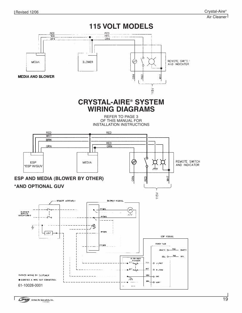
CRYSTAL-AIRE® SYSTEMWIRING DIAGRAMS
REFER TO PAGE 3OF THIS MANUAL FOR
INSTALLATION INSTRUCTIONS
115 VOLT MODELS
ESP AND MEDIA (BLOWER BY OTHER)
*AND OPTIONAL GUV
61-10028-0001
20
Revised 12/06 Crystal-Aire®
Air Cleaner
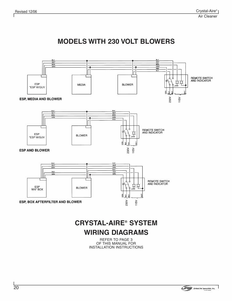
CRYSTAL-AIRE® SYSTEMWIRING DIAGRAMS
REFER TO PAGE 3OF THIS MANUAL FOR
INSTALLATION INSTRUCTIONS
MODELS WITH 230 VOLT BLOWERS
21
Revised 12/06 Crystal-Aire®
Air Cleaner
This page intentionally left blank
22
Revised 12/06 Crystal-Aire®
Air Cleaner
This page intentionally left blank
©1999, 2003, 2005 United Air SpecialistsPart No. 44-108712/06
United Air Specialists, Inc. reserves the right to change
design or specifications without notice.
4440 Creek Road • Cincinnati, Ohio 45242 USANational Phone: 1-800-252-4647
Telephone: (513) 891-0400 • Fax: (513) 891-4882http://www.uasinc.com
UNITED AIR SPECIALISTS, INC.LIMITED WARRANTY
UAS warrants to the original purchaser that all equipment will be free from defects in materials andworkmanship for one year from the date of shipment from UAS (three years for Smokeeter® andVisionAir™ models other than CC and DC series) and that major structural components on SFC and MCBseries will be free from defects in materials and workmanship for ten years from the date of shipment fromUAS. This warranty applies only if equipment is properly installed, maintained, and operated under normalconditions and does not apply to damage caused by corrosion, abrasion, abnormal use or misuse,misapplication, or normal wear and tear. This warranty will be void with respect to equipment that is subjectto unauthorized repairs or modifications. UAS makes no warranty as to goods manufactured or supplied byothers. This warranty is subject to any limitations in UAS’ quotation and may not be modified except by awritten instrument signed by the President or Vice President of Sales of UAS.
THIS WARRANTY IS EXCLUSIVE AND IN LIEU OF ALL OTHER WARRANTIES, WHETHERWRITTEN, ORAL OR IMPLIED, INCLUDING ANY IMPLIED WARRANTY OFMERCHANTABILITY, FITNESS FOR A PARTICULAR PURPOSE OR NONINFRINGEMENT.
As Purchaser's exclusive remedy for any defects in the equipment, UAS will exchange or repair anydefective parts during the warranty period, provided such parts are returned, prepaid, to UAS' factory. Theobligation of UAS is limited to furnishing replacement parts F.O.B. UAS' factory or making repairs at UAS'factory of any parts that are determined, upon inspection by UAS, to be defective. In no event will UAS beresponsible for labor or transportation charges for the removal, reshipment or reinstallation of the parts.
IN NO EVENT WILL UAS BE RESPONSIBLE FOR ANY SPECIAL OR CONSEQUENTIALDAMAGES.