Embed Size (px)
Citation preview

Modular Grease Trap MGTA
Installation Requirements
Water Corporation
22 Ethel Ave Brookvale NSW 2100 Postal: PO Box 255 Collaroy NSW 2097
Freecall 1800 626 753 Phone: 02 9939 8030 Fax: 02 9939 8027
Email: [email protected].
Halgan Installation Requirements
Halgan Pty Ltd - 10012017 Page 2
Modular Grease Trap Installation Requirements
For the Water Corporation Region 1.0 Design & Approvals 3
1.1 Permits and Approvals 3 1.2 Location 3 1.3 Sizing of TRAP and Grease Trap Chambers 3
2.0 Model Applicability 4 2.1 MGTA 4
3.0 Specification Drawing and Sizing 5 3.1 MGTA 5
3.1.1 General Drawing (MGTA) 5 3.1.2 Grease Trap Sizing (MGTA 5
3.4 Industrial Waste Sampling Point (IWSP) 6
4.0 Detailed Design & Installation Requirements 6 4.1. General 6 4.1.1 Location 6 4.1.2 Surcharge Relief Point 6 4.1.3 Inspection / Cleanout Points 6 4.1.4 Sampling Points 7 4.1.5 Piping Material 7 4.1.6 Garbage Disposal Units 7 4.1.7 Non Standard Installations 7 4.1.8 Health Requirements 7 4.1.9 Fire Resistance Level 7 4.1.10 Safety 7 4.1.10 Pumped Discharge from MGTA (Figure 1) 8 4.1.11 Pump Discharge to MGTA (Figure 2) 9 4.1.12 Typical Drainage Layout for MGTA (Figure 3) 10
4.2 Installation Requirements Modular Grease Trap 11 4.2.1 General 11 4.2.2 Installation Above Ground 11
4.2.2.1 Modular Grease Trap MGTA 11 4.2.3 Relief Overflow Point 11 4.2.4 Protection Barricades 11 4.2.5 Venting 11 4.2.6 Pipe Connection 11 4.2.6.1 Figure 1 12 4.2.6.2 Figure 2 12 4.2.7 Vacuum Pump-out Line 12
5.0 Vented Chambers 12 6.0 Warranty Card 13 7.0 Maintenance 14
7.1 Maintenance Frequency 14 7.2 Records 14 7.3 On – Site Cleaning Procedures 14 7.3.1 Modular Grease Trap (MGTA) 15
Halgan Installation Requirements
Halgan Pty Ltd - 10012017 Page 3
1.0 Design & Approvals
1.1 Permits and Approvals The MGT or MGT/S or MGTA hereafter both referred to as “TRAP” unless specified otherwise, must be installed in compliance with Water Corporation Regulations, Commercial & Industrial Services Section requirements, the WA Health Regulations and all relevant codes of practice. Before installation of the TRAP is commenced: 1. A duly completed Trade Waste Installation Form must be lodged with Water Corporation. The model and configuration of the proposed TRAP units must be stated on the form. 2. Plumbing/drainage acceptance must be obtained from the Water Corporation Commercial & Industrial Services Section. Approval of the WA Health Protection Service must be obtained if the TRAP is to be installed internally of a building. 3. It will be a condition of Water Corporation approval that the servicing and maintenance of the TRAP unit meet or exceed the requirements specified in this manual. 1.2 Location The licenced plumber will check the location for ease of contractor access to the vacuum pump out line. In case of doubt, the licenced plumber will request an authorised cleaning contractor to visit the site and provide written confirmation of their ability to properly service the TRAP. Water Corporation will not approve any installations which cannot be properly serviced. 1.3 Sizing of Grease Trap Chambers Sizing recommendations - refer to table on page 4. A correct application of the TRAP is important for maintaining an economical pumpout frequency. The following table indicates the factors, which have been found to be good indicators for determining the required model of MGT, MGTS or MGTA. Note: an economical pumpout frequency will also depend on good standards of housekeeping practice.
Halgan Installation Requirements
Halgan Pty Ltd - 10012017 Page 4
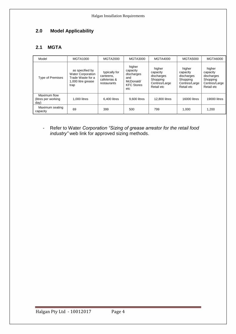
2.0 Model Applicability
2.1 MGTA
Model MGTA1000 MGTA2000 MGTA3000 MGTA4000 MGTA5000 MGTA6000
Type of Premises
as specified by Water Corporation Trade Waste for a 1,000 litre grease trap
typically for canteens, cafeterias & restaurants
higher capacity discharges and McDonald/ KFC Stores etc
higher capacity discharges Shopping Centres/Large Retail etc
higher capacity discharges Shopping Centres/Large Retail etc
higher capacity discharges Shopping Centres/Large Retail etc
Maximum flow (litres per working day)
1,000 litres 6,400 litres 9,600 litres 12,800 litres 16000 litres 19000 litres
Maximum seating capacity
69 399 500 799 1,000 1,200
- Refer to Water Corporation “Sizing of grease arrestor for the retail food industry” web link for approved sizing methods.
Halgan Installation Requirements
Halgan Pty Ltd - 10012017 Page 5
3.0 Specification Drawing and Sizing
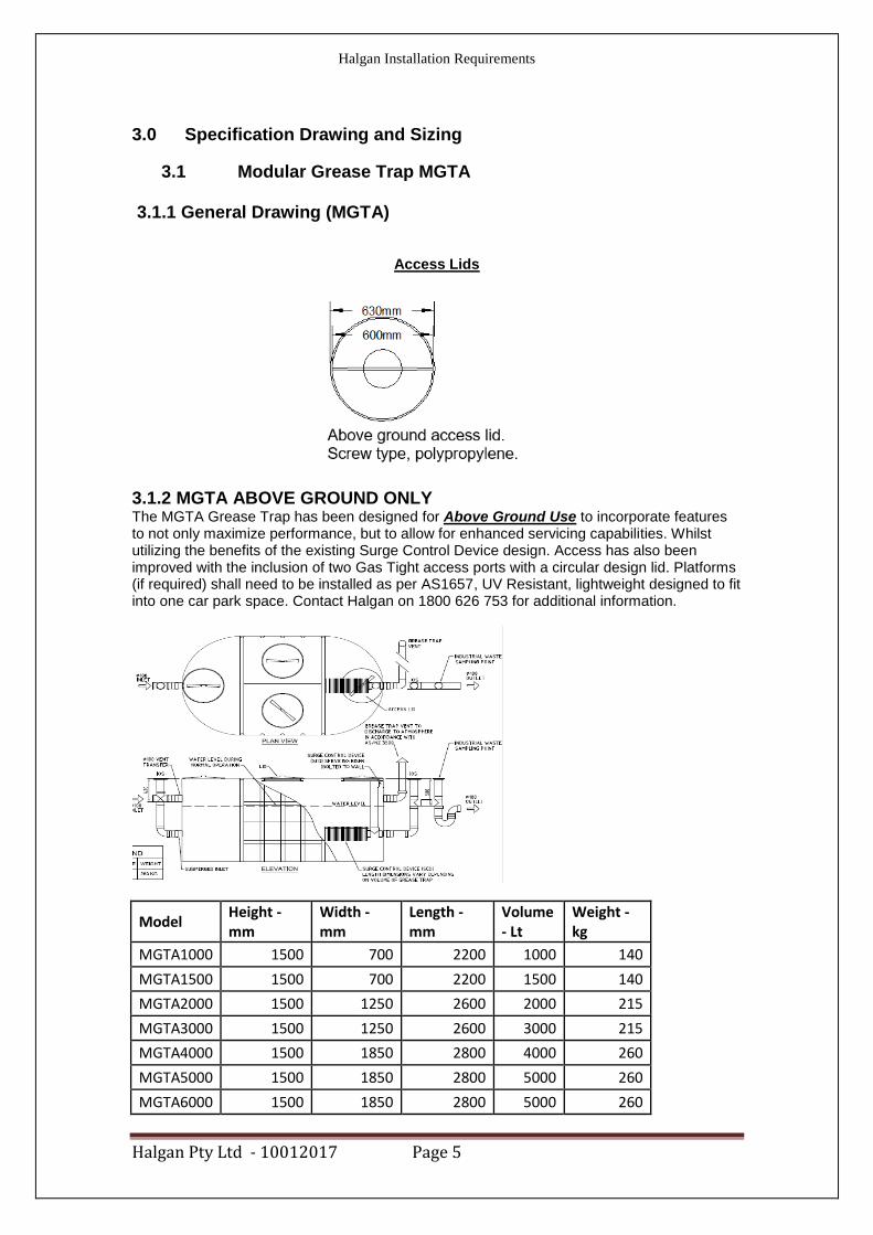
3.1 Modular Grease Trap MGTA 3.1.1 General Drawing (MGTA)
Access Lids
3.1.2 MGTA ABOVE GROUND ONLY The MGTA Grease Trap has been designed for Above Ground Use to incorporate features to not only maximize performance, but to allow for enhanced servicing capabilities. Whilst utilizing the benefits of the existing Surge Control Device design. Access has also been improved with the inclusion of two Gas Tight access ports with a circular design lid. Platforms (if required) shall need to be installed as per AS1657, UV Resistant, lightweight designed to fit into one car park space. Contact Halgan on 1800 626 753 for additional information.
Model Height - mm
Width - mm
Length - mm
Volume - Lt
Weight - kg
MGTA1000 1500 700 2200 1000 140
MGTA1500 1500 700 2200 1500 140
MGTA2000 1500 1250 2600 2000 215
MGTA3000 1500 1250 2600 3000 215
MGTA4000 1500 1850 2800 4000 260
MGTA5000 1500 1850 2800 5000 260
MGTA6000 1500 1850 2800 5000 260
Halgan Installation Requirements
Halgan Pty Ltd - 10012017 Page 6
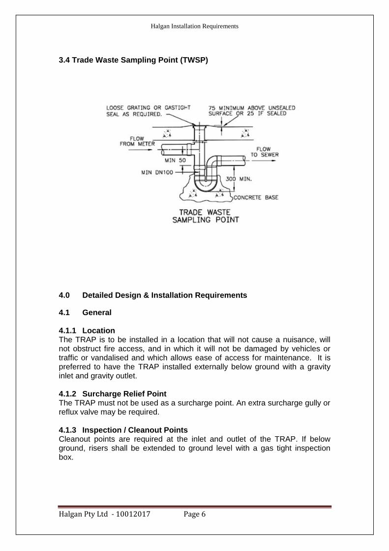
3.4 Trade Waste Sampling Point (TWSP)
4.0 Detailed Design & Installation Requirements
4.1 General 4.1.1 Location The TRAP is to be installed in a location that will not cause a nuisance, will not obstruct fire access, and in which it will not be damaged by vehicles or traffic or vandalised and which allows ease of access for maintenance. It is preferred to have the TRAP installed externally below ground with a gravity inlet and gravity outlet. 4.1.2 Surcharge Relief Point The TRAP must not be used as a surcharge point. An extra surcharge gully or reflux valve may be required. 4.1.3 Inspection / Cleanout Points Cleanout points are required at the inlet and outlet of the TRAP. If below ground, risers shall be extended to ground level with a gas tight inspection box.
Halgan Installation Requirements
Halgan Pty Ltd - 10012017 Page 7
4.1.4 Sampling Point Sampling points shall be provided at the outlet of the TRAP. If below ground, risers shall be extended to ground level and fitted with a gas tight inspection box. Refer to Water Corporation typical drawing HX33-11-30. 4.1.5 Piping Material Copper pipe and fittings shall not be used in trade waste installation as per AS/NZS 3500. 4.1.6 Garbage Disposal Units Garbage disposal units are a prohibited fixture within Water Corporation area of operations and must not be installed 4.1.7 Non Standard Installations Certain installations or position of installations that are unusual due to particular circumstances or matters not covered by this specification or local codes may be submitted to Halgan for consideration. Water Corporation trade waste approval for these situations will be considered on an individual basis.Water Corporation considers the proposed installation of the following tanks as non standard and therefore must be reviewed by Water Corporation Trade waste Assessors before any form of Trade waste approval is granted:
- MGTS3000, MGTS4000, MGTS5000 - MGTA3000, MGTA4000, MGTA5000, MGTA6000
4.1.8 Health Requirements The TRAP shall be designed and installed in such a way as not to cause a danger to health arising from leakage, blockage or surcharging. 4.1.9 Fire Resistance Level The TRAP is to be installed to maintain the Fire Resistance Level (F.R.L.) as specified in the Building Code of Australia. 4.1.10 Safety The carrying out of work covered in this Technical Manual shall comply with the safety requirements of the relevant Authorities.
Halgan Installation Requirements
Halgan Pty Ltd - 10012017 Page 8
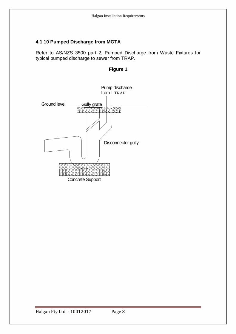
4.1.10 Pumped Discharge from MGTA Refer to AS/NZS 3500 part 2, Pumped Discharge from Waste Fixtures for typical pumped discharge to sewer from TRAP.
Figure 1
Pump discharge from MGT.
Concrete Support
Ground level
Disconnector gully
Gully grate
TRAP
Halgan Installation Requirements
Halgan Pty Ltd - 10012017 Page 9
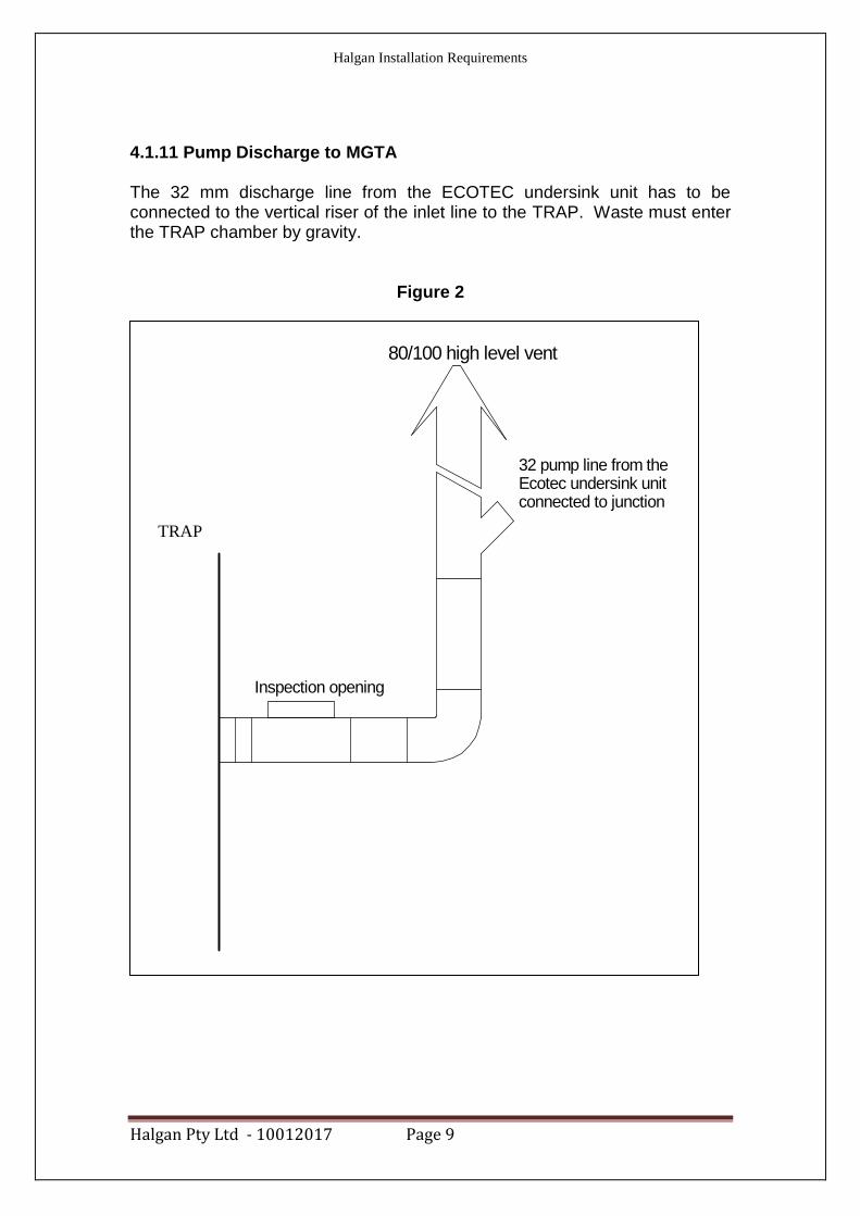
4.1.11 Pump Discharge to MGTA The 32 mm discharge line from the ECOTEC undersink unit has to be connected to the vertical riser of the inlet line to the TRAP. Waste must enter the TRAP chamber by gravity.
Figure 2
80/100 high level vent
32 pump line from the Ecotec undersink unit connected to junction
Inspection opening
Modular Grease Trap
TRAP
Halgan Installation Requirements
Halgan Pty Ltd - 10012017 Page 10
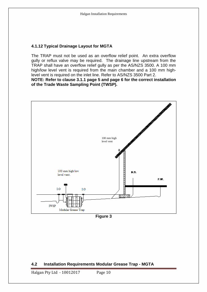
4.1.12 Typical Drainage Layout for MGTA The TRAP must not be used as an overflow relief point. An extra overflow gully or reflux valve may be required. The drainage line upstream from the TRAP shall have an overflow relief gully as per the AS/NZS 3500. A 100 mm high/low level vent is required from the main chamber and a 100 mm high-level vent is required on the inlet line. Refer to AS/NZS 3500 Part 2. NOTE: Refer to clause 3.1.1 page 5 and page 6 for the correct installation of the Trade Waste Sampling Point (TWSP).
Figure 3
4.2 Installation Requirements Modular Grease Trap - MGTA
100 mm high
level vent
Halgan Installation Requirements
Halgan Pty Ltd - 10012017 Page 11
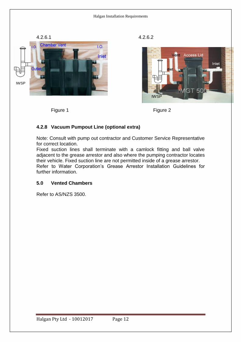
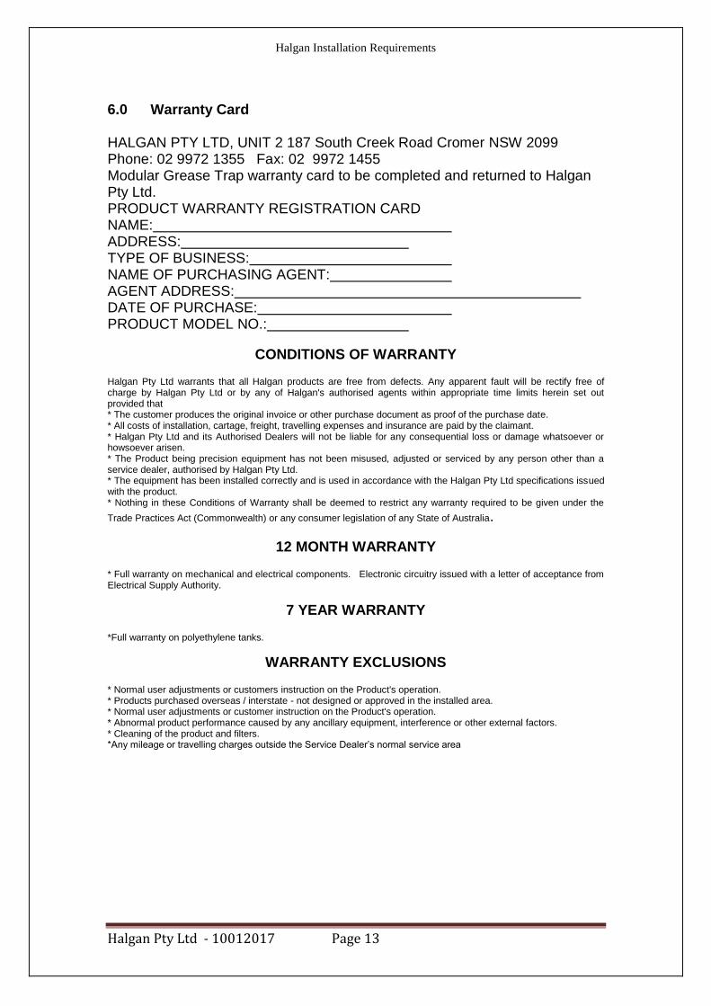
4.2.1 General The TRAP is to be installed in a location that will not cause a nuisance, obstruct fire access, cannot be vandalised or be damaged by vehicles. The TRAP must have ease of access to pumpout point for maintenance. A hose tap fitted with a Back Flow Protection Device (as per AS/NZS 3500) must be provided within 6 m of the TRAP for cleaning purposes. 4.2.2 Installation Above Ground 4.2.2.1 Installation above ground MGTA The MGTA are to be supported on a 100 mm thick concrete pad or on 98% compacted level ground with 20 mm sand base. The TRAP does not require a stand. All pipes connecting to the TRAP shall be fully supported; there should be no stress on the tank connections. All storm water must be diverted away from TRAP to prevent undermining of supports or foundations. 4.2.3 Relief Overflow Point The TRAP is not to be used as a surcharge point. An extra surcharge gully may be required or a reflux valve installed. Refer to figure in AS/NZS 3500 Part 2. The drainage line upstream from the TRAP shall have an overflow relief gully as per the AS/NZS 3500. 4.2.4 Protection Barricades and Safe Access Platforms The protection barricades shall be installed to protect the TRAP from physical damage. The posts shall be manufactured from 80 mm galvanised tube (refer to material specification) with a sealing cap at the top. A 400 mm white strip shall be painted at the top of the post. The posts will be 1300 mm long and approximately 800 mm apart. Above ground installations require safe access and as such a risk assessment may be required to determine if service platforms are required manufactured to Australian Standards 1657 for safe access to inspect and maintain the device as required. Refer to Water Corporation’s Grease Arrestor Installation Guidelines for further information. 4.2.5 Venting The high level vent on the inlet line shall be 100 mm. The high level vent shall terminate above the roofline and a high/low vent from the chamber as per AS/NZS 3500. Refer to AS/NZS 3500 Part 2. Air admittance valves are NOT TO BE USED in any part of the venting in the installation of the TRAP. 4.2.6 Pipe Connection Inlet connection is a double Y junction (figure 1) or in some council areas a 90 degree slope junction (figure 2) is allowed. The top connection of the TRAP is the vent transfer to high-level vent of the inlet drainage line. The middle connection of the TRAP is the liquid connection. The outlet connection is raised and the chamber vent at the outlet side is terminated as a low or high-level vent. Check council requirements.
Halgan Installation Requirements
Halgan Pty Ltd - 10012017 Page 12
4.2.6.1 4.2.6.2
Figure 1 Figure 2 4.2.8 Vacuum Pumpout Line (optional extra) Note: Consult with pump out contractor and Customer Service Representative for correct location. Fixed suction lines shall terminate with a camlock fitting and ball valve adjacent to the grease arrestor and also where the pumping contractor locates their vehicle. Fixed suction line are not permitted inside of a grease arrestor. Refer to Water Corporation’s Grease Arrestor Installation Guidelines for further information. 5.0 Vented Chambers Refer to AS/NZS 3500.
IWSP
IWSP
Halgan Installation Requirements
Halgan Pty Ltd - 10012017 Page 13
6.0 Warranty Card HALGAN PTY LTD, UNIT 2 187 South Creek Road Cromer NSW 2099 Phone: 02 9972 1355 Fax: 02 9972 1455
Modular Grease Trap warranty card to be completed and returned to Halgan Pty Ltd. PRODUCT WARRANTY REGISTRATION CARD
NAME: ADDRESS: TYPE OF BUSINESS: NAME OF PURCHASING AGENT: AGENT ADDRESS: DATE OF PURCHASE: PRODUCT MODEL NO.:
CONDITIONS OF WARRANTY
Halgan Pty Ltd warrants that all Halgan products are free from defects. Any apparent fault will be rectify free of charge by Halgan Pty Ltd or by any of Halgan's authorised agents within appropriate time limits herein set out provided that * The customer produces the original invoice or other purchase document as proof of the purchase date. * All costs of installation, cartage, freight, travelling expenses and insurance are paid by the claimant. * Halgan Pty Ltd and its Authorised Dealers will not be liable for any consequential loss or damage whatsoever or howsoever arisen. * The Product being precision equipment has not been misused, adjusted or serviced by any person other than a service dealer, authorised by Halgan Pty Ltd. * The equipment has been installed correctly and is used in accordance with the Halgan Pty Ltd specifications issued with the product. * Nothing in these Conditions of Warranty shall be deemed to restrict any warranty required to be given under the
Trade Practices Act (Commonwealth) or any consumer legislation of any State of Australia.
12 MONTH WARRANTY
* Full warranty on mechanical and electrical components. Electronic circuitry issued with a letter of acceptance from Electrical Supply Authority.
7 YEAR WARRANTY
*Full warranty on polyethylene tanks.
WARRANTY EXCLUSIONS
* Normal user adjustments or customers instruction on the Product's operation. * Products purchased overseas / interstate - not designed or approved in the installed area. * Normal user adjustments or customer instruction on the Product's operation. * Abnormal product performance caused by any ancillary equipment, interference or other external factors. * Cleaning of the product and filters. *Any mileage or travelling charges outside the Service Dealer’s normal service area
Halgan Installation Requirements
Halgan Pty Ltd - 10012017 Page 14
7.0 Maintenance
7.1 Maintenance Frequency Any TRAP installed internally or at a location where it might cause an objection on health grounds must be on a maximum pump out frequency of eight weeks or less. In all other applications, the TRAP will be pumped out at a maximum of 3 months or when a floating layer of 75 mm grease has formed on the surface. In all locations, Water Corporation sets the clean out schedule. Note: The pump out frequency will depend on the house keeping within the premises. 7.2 Records The customer shall keep, and make available, records pertaining to clean outs as specified in permit to discharge. 7.3 On-Site Cleaning Procedures 7.3.1 Modular Grease Trap (MGTA) The TRAP installation must be maintained as follows: · Clean outs must be undertaken by approved waste collection contractor
· The contractor should make a visual observation every time they clean the TRAP to make sure it is on the correct maintenance frequency. The trade waste customer will have to be notified. Water Corporation will determine the pump out frequency.
· Remove all the TRAP access lids and access port lids, from the traps. Insert the vacuum hose into the 100 mm SCD servicing pipe in the downstream TRAP unit. Turn the vacuum pump on for 5 seconds. Insert the vacuum hose into the access chamber of the upstream TRAP unit and remove the greasy liquid waste from the TRAP. If access is available turn the kitchen taps on to flush out the drainage line and help the cleaning process. Then insert the vacuum hose into access lid and remove any residual liquid waste. Repeat Step 3 and Step 4 in the remaining TRAP units working downstream. Then use the designated hose tap to connect the hose for cleaning of the Modular Grease Trap. At this time, hose down the SCD unit. Check the security of the SCD unit. Replace access lids and complete the appropriate servicing documents. · If the plates from the SCD are damaged in any way then the SCD must be repaired or replaced immediately. If the connection of SCD has been broken or other plumbing connections have failed then these must be replaced immediately. The waste contractor should note on their clearance reports any damaged and failure of the SCD and plumbing pipework connecting the SCD.
Halgan Installation Requirements
Halgan Pty Ltd - 10012017 Page 15
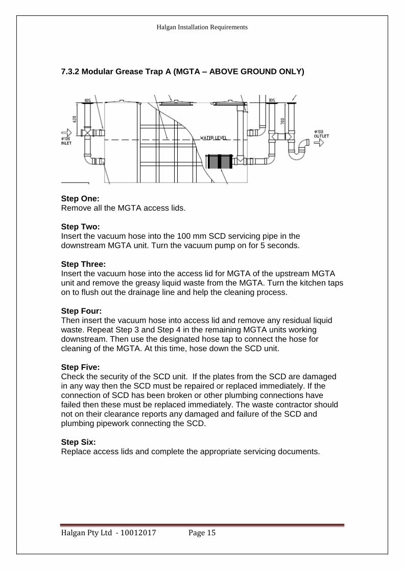
7.3.2 Modular Grease Trap A (MGTA – ABOVE GROUND ONLY)
Step One: Remove all the MGTA access lids. Step Two: Insert the vacuum hose into the 100 mm SCD servicing pipe in the downstream MGTA unit. Turn the vacuum pump on for 5 seconds. Step Three: Insert the vacuum hose into the access lid for MGTA of the upstream MGTA unit and remove the greasy liquid waste from the MGTA. Turn the kitchen taps on to flush out the drainage line and help the cleaning process. Step Four: Then insert the vacuum hose into access lid and remove any residual liquid waste. Repeat Step 3 and Step 4 in the remaining MGTA units working downstream. Then use the designated hose tap to connect the hose for cleaning of the MGTA. At this time, hose down the SCD unit. Step Five: Check the security of the SCD unit. If the plates from the SCD are damaged in any way then the SCD must be repaired or replaced immediately. If the connection of SCD has been broken or other plumbing connections have failed then these must be replaced immediately. The waste contractor should not on their clearance reports any damaged and failure of the SCD and plumbing pipework connecting the SCD. Step Six: Replace access lids and complete the appropriate servicing documents.