Embed Size (px)
Citation preview
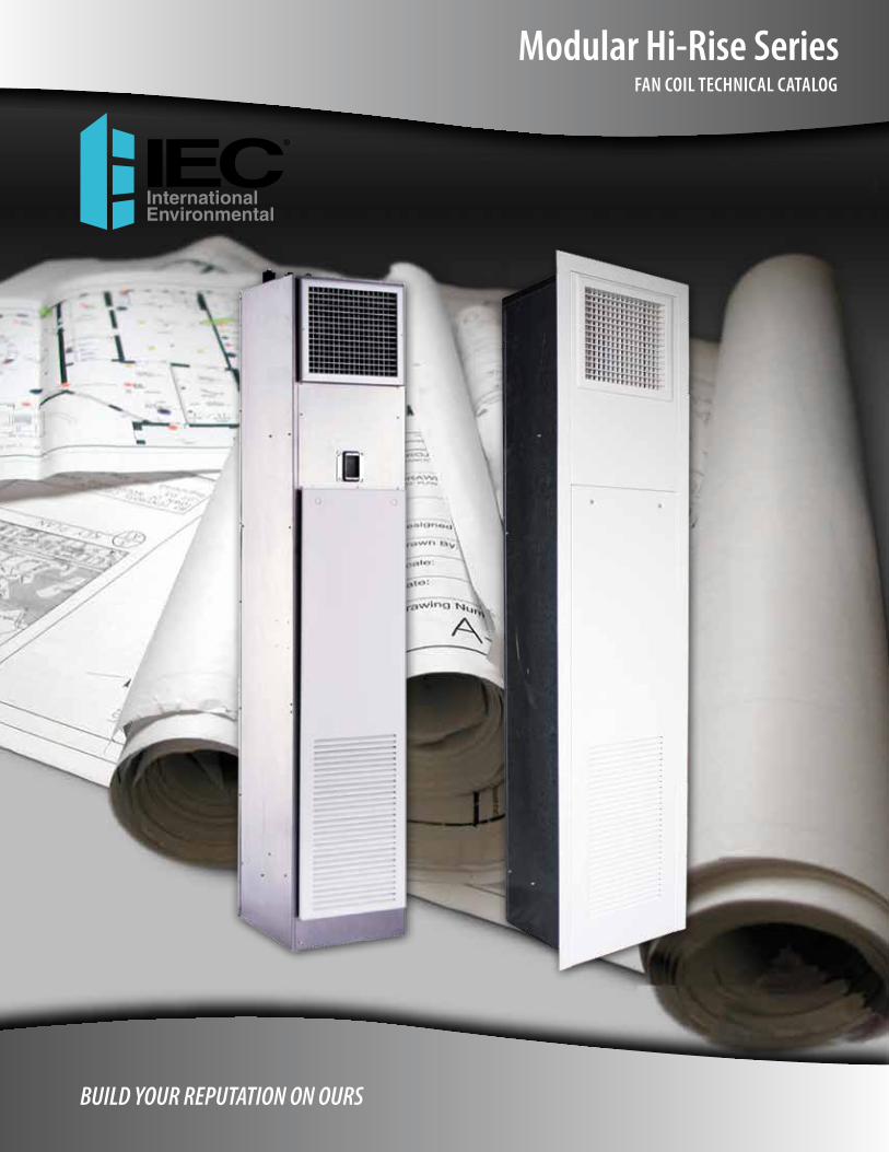
BUILD YOUR REPUTATION ON OURS
Modular Hi-Rise SeriesFAN COIL TECHNICAL CATALOG
International Environmental Corporation • Modular Hi-Rise Series Fan Coil Technical Catalogwww.iec-okc.com2
Modular Hi-Rise Series
International Environmental Corporation (IEC) works continually
to improve its products. As a result, the design and specifications
of each product may be changed without notice and may not be
as described herein. Please contact IEC for information regarding
current design and product specifications. Statements and
other information contained herein are not express warranties
and do not form the basis of any bargain between the parties
but are merely IEC’s opinion or commendation of its products.
Manufacturer’s standard limited warranty applies.
International Environmental Corporation • Modular Hi-Rise Series Fan Coil Technical Catalogwww.iec-okc.com
Modular Hi-Rise Series
3
TABLE OF CONTENTS
3 Table of Contents
4 Portfolio
5 Features and Benefits
7 Product Application
11 Unit Model Key
12 Ratings and Listings
13 Fan Performance Curves
16 Electric Heating
17 Motor Data
18 Submittal Data
25 Standard Features and Options
International Environmental Corporation • Modular Hi-Rise Series Fan Coil Technical Catalogwww.iec-okc.com4
Modular Hi-Rise SeriesPORTFOLIO
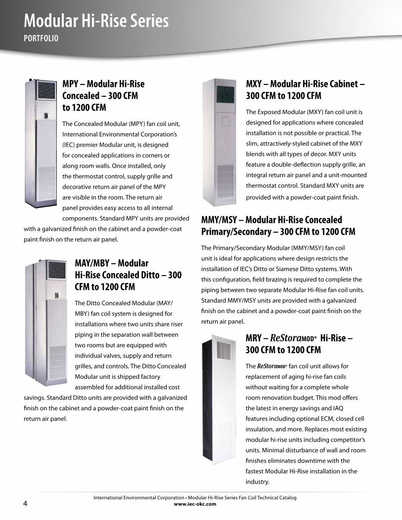
MXY – Modular Hi-Rise Cabinet – 300 CFM to 1200 CFMThe Exposed Modular (MXY) fan coil unit is
designed for applications where concealed
installation is not possible or practical. The
slim, attractively-styled cabinet of the MXY
blends with all types of decor. MXY units
feature a double-deflection supply grille, an
integral return air panel and a unit-mounted
thermostat control. Standard MXY units are
provided with a powder-coat paint finish.
MMY/MSY – Modular Hi-Rise Concealed Primary/Secondary – 300 CFM to 1200 CFMThe Primary/Secondary Modular (MMY/MSY) fan coil
unit is ideal for applications where design restricts the
installation of IEC’s Ditto or Siamese Ditto systems. With
this configuration, field brazing is required to complete the
piping between two separate Modular Hi-Rise fan coil units.
Standard MMY/MSY units are provided with a galvanized
finish on the cabinet and a powder-coat paint finish on the
return air panel.
MRY – ReStoraMOD® Hi-Rise – 300 CFM to 1200 CFMThe ReStoraMOD® fan coil unit allows for
replacement of aging hi-rise fan coils
without waiting for a complete whole
room renovation budget. This mod offers
the latest in energy savings and IAQ
features including optional ECM, closed cell
insulation, and more. Replaces most existing
modular hi-rise units including competitor’s
units. Minimal disturbance of wall and room
finishes eliminates downtime with the
fastest Modular Hi-Rise installation in the
industry.
MPY – Modular Hi-Rise Concealed – 300 CFM to 1200 CFMThe Concealed Modular (MPY) fan coil unit,
International Environmental Corporation’s
(IEC) premier Modular unit, is designed
for concealed applications in corners or
along room walls. Once installed, only
the thermostat control, supply grille and
decorative return air panel of the MPY
are visible in the room. The return air
panel provides easy access to all internal
components. Standard MPY units are provided
with a galvanized finish on the cabinet and a powder-coat
paint finish on the return air panel.
MAY/MBY – Modular Hi-Rise Concealed Ditto – 300 CFM to 1200 CFMThe Ditto Concealed Modular (MAY/
MBY) fan coil system is designed for
installations where two units share riser
piping in the separation wall between
two rooms but are equipped with
individual valves, supply and return
grilles, and controls. The Ditto Concealed
Modular unit is shipped factory
assembled for additional installed cost
savings. Standard Ditto units are provided with a galvanized
finish on the cabinet and a powder-coat paint finish on the
return air panel.
International Environmental Corporation • Modular Hi-Rise Series Fan Coil Technical Catalogwww.iec-okc.com
Modular Hi-Rise Series
5
FEATURES AND BENEFITS
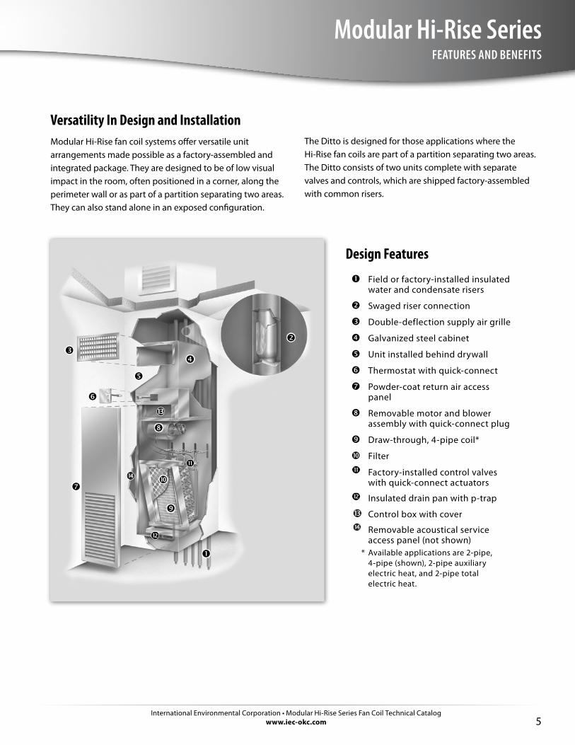
Versatility In Design and InstallationModular Hi-Rise fan coil systems offer versatile unit arrangements made possible as a factory-assembled and integrated package. They are designed to be of low visual impact in the room, often positioned in a corner, along the perimeter wall or as part of a partition separating two areas. They can also stand alone in an exposed configuration.
Design Features
Field or factory-installed insulated water and condensate risers
Swaged riser connection
Double-deflection supply air grille
Galvanized steel cabinet
Unit installed behind drywall
Thermostat with quick-connect
Powder-coat return air access panel
Removable motor and blower assembly with quick-connect plug
Draw-through, 4-pipe coil*
Filter
Factory-installed control valves with quick-connect actuators
Insulated drain pan with p-trap
Control box with cover
Removable acoustical service access panel (not shown)
* Available applications are 2-pipe, 4-pipe (shown), 2-pipe auxiliary electric heat, and 2-pipe total electric heat.
The Ditto is designed for those applications where the Hi-Rise fan coils are part of a partition separating two areas. The Ditto consists of two units complete with separate valves and controls, which are shipped factory-assembled with common risers.
International Environmental Corporation • Modular Hi-Rise Series Fan Coil Technical Catalogwww.iec-okc.com6
Modular Hi-Rise SeriesFEATURES AND BENEFITS, Cont’d.
Application Fit• Exposed and concealed cabinets with 45 possible
airflow configurations provide solutions for multiple applications.
• A variety of aesthetically pleasing return and supply grilles will blend with most décors.
• Thermostats are available as unit, surface, wall or ADA mounted for ease of human interface.
• Units are specifically designed for quiet operation.
Design Flexibility• Easy to use computer rating program to speed up
project design.• Wide variety of coil configurations to match the
heating and cooling loads of the space. Coils with different pressure drops to meet the needs of custom applications are also available.
• Standard motor/blower assemblies to meet the needs of applications where duct work is required.
• Customizable cabinetry is available for special applications. Ideal for new construction and renovation projects.
• Optional Ditto fan coil designed to serve two separate rooms using UL listed one-hour fire-rated riser chase.
• Multiple riser locations for total flexibility.• Wide variety of valve packages factory installed to
meet desired control specifications.• Manual or motorized outside air dampers are available
to meet ventilation requirements and reduce field labor.
• Several MERV rated filter media available to address IAQ requirements.
• Extensive offering of control options available.• Wide variety of insulation material available to address
IAQ concerns.• Heavy galvanized or stainless steel drain pan with pre-
formed rubber p-trap.
Ease of Installation• Units assembled at the factory in coordination with
the jobsite construction schedule.• Riser length is matched to the job specifications and
pre-fabricated with the specified material. Risers are factory installed or shipped separately.
• Risers swaged to reduce field brazing labor and to ensure the integrity of the connections.
• Drywall can be applied directly to the surface of the concealed unit with factory provided duct collars and drywall stops to ensure a high quality finished appearance.
• Control box at eye level for ease of field wiring and easy access.
Ease of Service• Filters are easily accessible by removing return air
panel.• Motor and blower are removable with quick-connect
plug.• Control box is easily accessible and at eye level.
Quality and Safety• Every unit tested and inspected at the factory for
trouble free start-up.• ETL listed• AHRI certified
International Environmental Corporation • Modular Hi-Rise Series Fan Coil Technical Catalogwww.iec-okc.com
Modular Hi-Rise Series
7
PRODUCT APPLICATION
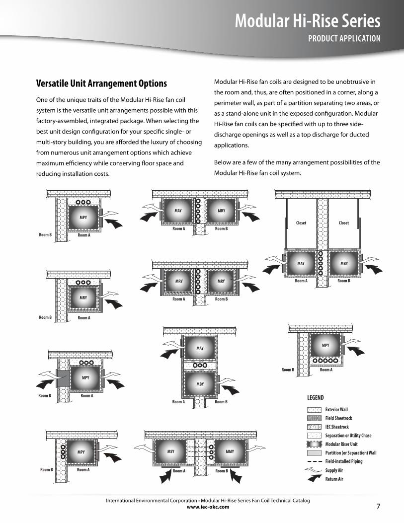
Versatile Unit Arrangement OptionsOne of the unique traits of the Modular Hi-Rise fan coil
system is the versatile unit arrangements possible with this
factory-assembled, integrated package. When selecting the
best unit design configuration for your specific single- or
multi-story building, you are afforded the luxury of choosing
from numerous unit arrangement options which achieve
maximum efficiency while conserving floor space and
reducing installation costs.
Modular Hi-Rise fan coils are designed to be unobtrusive in
the room and, thus, are often positioned in a corner, along a
perimeter wall, as part of a partition separating two areas, or
as a stand-alone unit in the exposed configuration. Modular
Hi-Rise fan coils can be specified with up to three side-
discharge openings as well as a top discharge for ducted
applications.
Below are a few of the many arrangement possibilities of the
Modular Hi-Rise fan coil system.
Exterior Wall
LEGEND
Field Sheetrock
IEC Sheetrock
Separation or Utility Chase
Modular Riser Unit
Field-installed Piping
Partition (or Separation) Wall
Supply Air
Return Air
Room ARoom B
MPY
MPY
Room ARoom B
MPY
Room ARoom B
MSY MMY
Room A Room B
MPY
Room ARoom B
MAY MBY
Room A Room B
MAY MBY
Room A Room B
Closet Closet
MAY
MBY
Room A Room B
MRY
Room ARoom B
Room A Room B
MRYMRY
International Environmental Corporation • Modular Hi-Rise Series Fan Coil Technical Catalogwww.iec-okc.com8
Modular Hi-Rise SeriesPRODUCT APPLICATION, Cont’d.
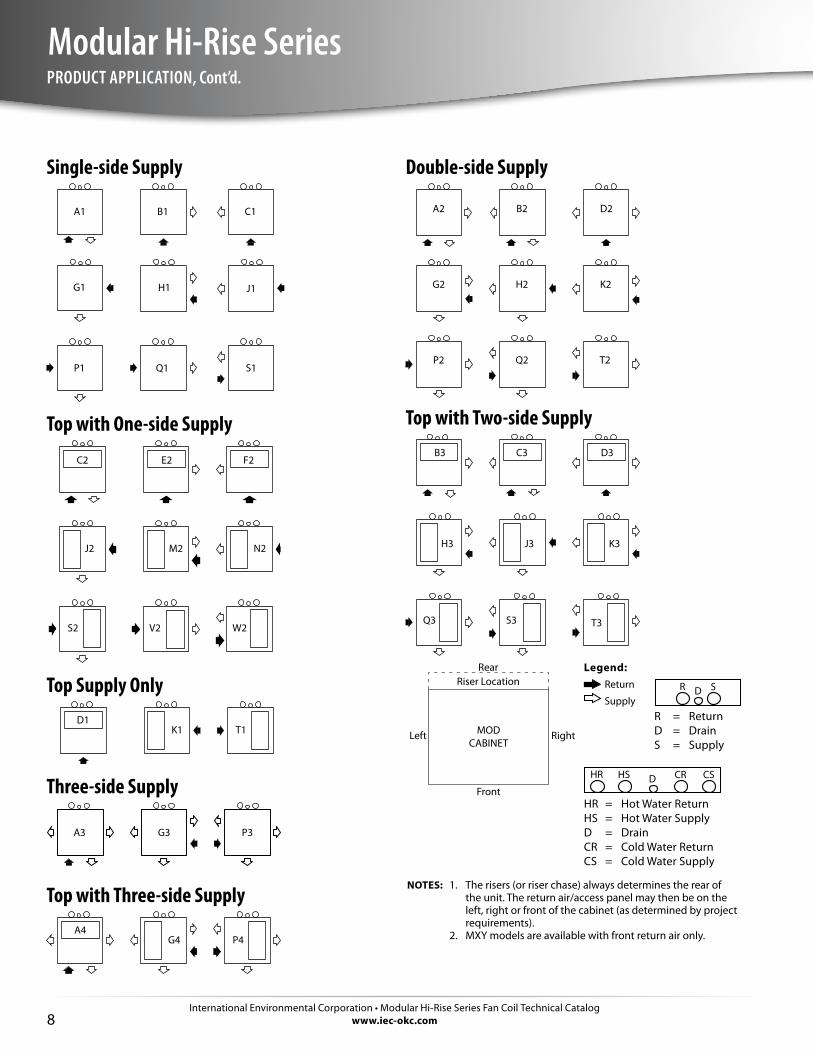
Double-side Supply
A2 B2 D2
K2H2G2
T2Q2P2
Top with Two-side SupplyB3 C3 D3
H3 J3 K3
Q3 S3 T3
RearRiser Location
MODCABINET
Right
Front
Left
Single-side Supply
A1
S1Q1P1
J1H1G1
C1B1
Top with One-side Supply
C2 E2 F2
N2
W2V2S2
M2J2
Top Supply OnlyD1
K1 T1
Three-side Supply
A3 G3 P3
Top with Three-side SupplyA4
G4 P4
Legend:Return
Supply
HR = Hot Water ReturnHS = Hot Water SupplyD = DrainCR = Cold Water ReturnCS = Cold Water Supply
D CRHS CSHR
R = ReturnD = DrainS = Supply
R D S
NOTES: 1. The risers (or riser chase) always determines the rear of the unit. The return air/access panel may then be on the left, right or front of the cabinet (as determined by project requirements).
2. MXY models are available with front return air only.
International Environmental Corporation • Modular Hi-Rise Series Fan Coil Technical Catalogwww.iec-okc.com
Modular Hi-Rise Series
9
PRODUCT APPLICATION, Cont’d.
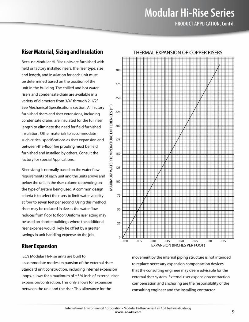
.000 .005 .030.025.020.015.010 .035
THERMAL EXPANSION OF COPPER RISERS
EXPANSION (INCHES PER FOOT)
300
275
250
225
200
175
125
100
75
50
25
0
150
MA
XIM
UM
WAT
ER T
EMPE
RATU
RE D
IFFE
REN
CES
(ºF)
movement by the internal piping structure is not intended
to replace necessary expansion compensation devices
that the consulting engineer may deem advisable for the
external riser system. External riser expansion/contraction
compensation and anchoring are the responsibility of the
consulting engineer and the installing contractor.
Riser Material, Sizing and InsulationBecause Modular Hi-Rise units are furnished with
field or factory installed risers, the riser type, size
and length, and insulation for each unit must
be determined based on the position of the
unit in the building. The chilled and hot water
risers and condensate drain are available in a
variety of diameters from 3/4" through 2-1/2".
See Mechanical Specifications section. All factory
furnished risers and riser extensions, including
condensate drains, are insulated for the full riser
length to eliminate the need for field furnished
insulation. Other materials to accommodate
such critical specifications as riser expansion and
between-the-floor fire proofing must be field
furnished and installed by others. Consult the
factory for special Applications.
Riser sizing is normally based on the water flow
requirements of each unit and the units above and
below the unit in the riser column depending on
the type of system being used. A common design
criteria is to select the risers to limit water velocity
at four to seven feet per second. Using this method,
risers may be reduced in size as the water flow
reduces from floor to floor. Uniform riser sizing may
be used on shorter buildings where the additional
riser expense would likely be offset by a greater
savings in unit handling expense on the job.
Riser ExpansionIEC’s Modular Hi-Rise units are built to
accommodate modest expansion of the external risers.
Standard unit construction, including internal expansion
loops, allows for a maximum of ±3/4-inch of external riser
expansion/contraction. This only allows for expansion
between the unit and the riser. This allowance for the

International Environmental Corporation • Modular Hi-Rise Series Fan Coil Technical Catalogwww.iec-okc.com10
Modular Hi-Rise SeriesPRODUCT APPLICATION, Cont’d.
PRES
SURE
DRO
P –
FT. W
ATER
/ 10
0 FT
. OF
RISE
R
WATER FLOW RATE– GPM
100 90 80 70
60
50
40
30
20
10 9.0 8.0 7.0 6.0
5.0
4.0
3.0
2.0
1.0 .9 .8 .7 .6
.5
.4
.3
.2
.1
100 90 80 70
60
50
40
30
20
10 9.0 8.0 7.0 6.0
5.0
4.0
3.0
2.0
1.0 .9 .8 .7 .6
.5
.4
.3
.2
.1
1.0 2.0 3.0 4.0 5.0 6.0 8.0 10 20 30 40 50 60 80 100 200 300
1.0 2.0 3.0 4.0 5.0 6.0 8.0 10 20 30 40 50 60 80 100 200 300
1½ In
ch N
omin
al
6 FPS
5 FPS
4 FPS
3 FPS
2 FPS
8 FPS7 FPS
¾ In
ch N
omin
al
1 In
ch N
omin
al
1¼ In
ch N
omin
al
2½ In
ch N
omin
al
2 In
ch N
omin
al
3 In
ch N
omin
al
4 In
ch N
omin
al
International Environmental Corporation • Modular Hi-Rise Series Fan Coil Technical Catalogwww.iec-okc.com
Modular Hi-Rise Series
11
UNIT MODEL KEY
ThermostatFunction Control
***********
Note that kWs depend on voltage and unit size.For additional codes check the price sheet.Consult factory for pricing.
03 • 300 CFM04 • 400 CFM06 • 600 CFM08 • 800 CFM10 • 1000 CFM12 • 1200 CFM
Two-pipe Cooling and Heatingor Four-pipe Cooling
A • 3 RowB • 4 RowR • 3 Row, AAVS • 4 Row, AAV
Four-pipeHeating
Y • None6 • 1 Row Water
Heating7 • 2 Row Water
Heating
Voltage
C • 115-1-60D • 208-1-60E • 230-1-60F • 277-1-60
SINGLE SUPPLY**
ARR Code Return SupplyA1 Front FrontB1 Front RightC1 Front LeftD1 Front Top
DOUBLE SUPPLY**
ARR Code Return SupplyA2 Front Front/RightB2 Front Front/LeftC2 Front Front/TopD2 Front Right/LeftE2 Front Right/TopF2 Front Left/Top
Voltage
B • 24 V
C • 120 V
D • 208 VE • 240 VF • 277 V
System/Thermostat
Manual Fan Operation
A1 • Standard Unit Mount (Switch Only)
G • 2-Pipe Heat OnlyH • 2-Pipe Cool OnlyJ • 2-Pipe Heat and Cool, MCOK • 2-Pipe Heat and Cool, ACOL • 2-Pipe Heat and Cool w/ Aux. Elec. Heat, MCOM • 2-Pipe Heat and Cool w/ Aux. Elec. Heat, ACON • 2-Pipe Cool w/ Total Elec. Heat, MCOP • 2-Pipe Cool w/ Total Elec. Heat, ACOQ • 4-Pipe Heat and Cool, MCOR • 4-Pipe Heat and Cool, ACO
Type
2 • Permanent Split Capacitor
kW*
B • 1.00C • 1.50D • 2.00F • 3.00G • 4.00
Coil
A • 3 RowB • 4 Row
Voltage
C • 115-1-60D • 208-1-60E • 230-1-60F • 277-1-60
H • 5.00J • 6.00L • 8.00N • 10.00Y • No Electric Heat
Y •S •
CoilConnection
None Same End
CoilConstruction
Y • StdS • SS Wrapper
C • Unit Mounted Series 1564 • Wall Series 4039A • Wall Series 155 VerticalB • Wall Series 155 HorizontalP • 24 V Digital Programmable Wall SeriesN • 24 V Digital Non-Programmable Wall Series
Coil Construction
Y • StdS • SS Wrapper
MPY • Modular ConcealedMAY • Modular Concealed (Ditto-A)MBY • Modular Concealed (Ditto-B)MMY • Modular Concealed (Primary)MRY • Modular ReStoraMOD® Concealed MSY • Modular Concealed (Secondary)MXY • Modular Cabinet
Code ItemsUnit Code
MOTOR
05C 2
SIZE
030 4
CONTROLS
07C 4P
COILSw/ELECTRIC HEAT
04aC YA C
VINTAGEUNIT
02Y
01M P
COILS
04Y YA Y
ARRANGEMENT
06A 1
International Environmental Corporation • Modular Hi-Rise Series Fan Coil Technical Catalogwww.iec-okc.com12
Modular Hi-Rise SeriesRATINGS AND LISTINGS
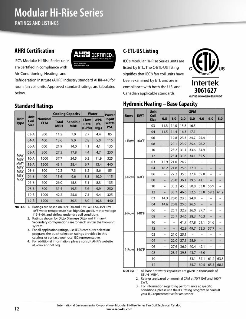
C-ETL-US ListingIEC’s Modular Hi-Rise Series units are
listed by ETL. The C-ETL-US listing
signifies that IEC’s fan coil units have
been examined by ETL and are in
compliance with both the U.S. and
Canadian applicable standards.
Hydronic Heating – Base Capacity
Rows EWTUnit Coil Size
GPM
0.5 1.0 2.0 3.0 4.0 6.0 8.0
1-Row 160˚F
03 11.3 14.0 15.8 16.5 – – –
04 11.5 14.4 16.3 17.1 – – –
06 – 19.8 23.3 24.7 25.4 – –
08 – 20.1 23.9 25.4 26.2 – –
10 – 25.2 31.1 33.6 34.9 – –
12 – 25.4 31.6 34.1 35.5 – –
2-Row 160˚F
03 15.9 21.0 24.2 – – – –
04 16.2 21.8 25.6 27.0 – – –
06 – 27.2 35.5 37.4 39.0 – –
08 – 28.0 36.1 39.5 41.1 – –
10 – 33.2 45.5 50.8 53.8 56.9 –
12 – 33.7 46.6 52.5 55.8 59.3 61.2
3-Row 140˚F
03 14.3 20.0 23.5 24.8 – – –
04 14.6 20.8 25.0 26.5 – – –
06 – 25.1 32.9 36.0 37.7 – –
08 – 25.7 34.6 38.3 40.3 – –
10 – – 41.7 47.8 51.1 54.6 –
12 – – 42.9 49.7 53.5 57.7 –
4-Row 140˚F
03 – 21.0 25.1 – – – –
04 – 22.0 27.1 28.9 – – –
06 – 27.6 36.9 40.4 42.1 – –
08 – 28.4 39.3 43.7 46.0 – –
10 – – – 53.1 57.1 61.2 63.3
12 – – – 55.7 60.5 65.5 68.1
NOTES: 1. All base hot water capacities are given in thousands of BTUH (MBH).
2. Ratings are based on nominal CFM at 70°F EAT and 160°F EWT.
3. For information regarding performance at specific conditions, please use the IEC rating program or consult your IEC representative for assistance.
AHRI CertificationIEC’s Modular Hi-Rise Series units
are certified in compliance with
Air-Conditioning, Heating, and
Refrigeration Institute (AHRI) industry standard AHRI-440 for
room fan coil units. Approved standard ratings are tabulated
below.
Standard Ratings
Unit Type
Unit Coil Size
Nominal CFM
Cooling Capacity Water Power Input Watts
PSCTotal MBH
Sensible MBH
Flow Rate
(GPM)
WPD (ft.
wg.)
MAY MBY MMY MPYMRYMSYMXY
03-A 300 11.5 7.0 2.7 4.4 85
04-A 400 13.6 9.0 2.8 5.0 115
06-A 600 21.9 14.0 4.1 4.1 135
08-A 800 27.5 17.8 4.4 4.7 250
10-A 1000 37.7 24.5 6.3 11.9 325
12-A 1200 43.1 28.4 6.7 13.4 440
03-B 300 12.2 7.3 3.2 8.6 85
04-B 400 15.6 9.6 3.5 10.0 115
06-B 600 26.0 15.3 5.1 8.3 135
08-B 800 31.4 19.5 5.6 9.9 250
10-B 1000 42.2 25.6 7.5 9.4 325
12-B 1200 46.5 30.5 8.0 10.8 440
NOTES: 1. Ratings are based on 80°F DB and 67°F WB EAT, 45°F EWT, 10°F water temperature rise, high fan speed, motor voltage 115-1-60, and airflow under dry coil conditions.
2. Ratings shown for Ditto, Siamese Ditto and Primary/Secondary configurations are for each unit in the two-unit system.
3. For all application ratings, use IEC’s computer selection program, the quick-selection ratings provided in this catalog, or contact your local IEC representative.
4. For additional information, please consult AHRI’s website at www.ahrinet.org.
3061627HEATING AND COOLING EQUIPMENT
International Environmental Corporation • Modular Hi-Rise Series Fan Coil Technical Catalogwww.iec-okc.com
Modular Hi-Rise Series
13
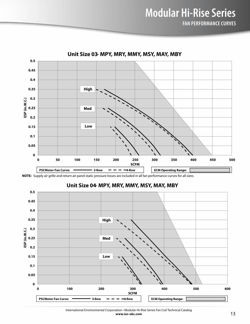
FAN PERFORMANCE CURVES
0
0.05
0.1
0.15
0.2
0.25
0.3
0.35
0.4
0.45
0.5
0 50 100 150 200 250 300 350 400 450 500
ESP
(in.W
.C.)
SCFM
Unit Size 03 - MPY, MRY, MMY, MSY, MAY, MBY
PSC Motor Fan Curve: 3-Row 4-Row ECM Operating Range:
Low
Med
High
NOTE: Supply air grille and return air panel static pressure losses are included in all fan performance curves for all sizes.
0
0.05
0.1
0.15
0.2
0.25
0.3
0.35
0.4
0.45
0.5
0 100 200 300 400 500 600
ESP
(in.W
.C.)
SCFM
Unit Size 04 - MPY, MRY, MMY, MSY, MAY, MBY
PSC Motor Fan Curve: 3-Row 4-Row ECM Operating Range:
Low
Med
High
International Environmental Corporation • Modular Hi-Rise Series Fan Coil Technical Catalogwww.iec-okc.com14
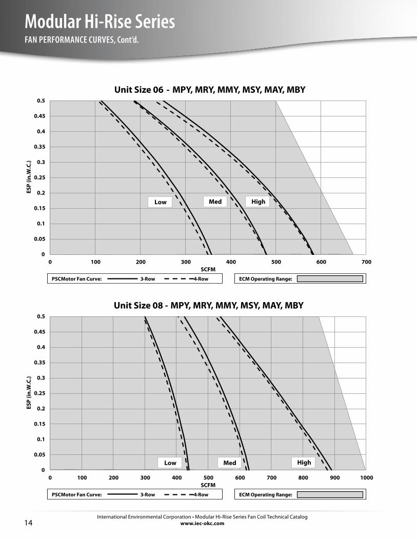
Modular Hi-Rise SeriesFAN PERFORMANCE CURVES, Cont’d.
0
0.05
0.1
0.15
0.2
0.25
0.3
0.35
0.4
0.45
0.5
0 100 200 300 400 500 600 700
ESP
(in.W
.C.)
SCFM
Unit Size 06 - MPY, MRY, MMY, MSY, MAY, MBY
PSC Motor Fan Curve: 3-Row 4-Row ECM Operating Range:
Low Med High
0
0.05
0.1
0.15
0.2
0.25
0.3
0.35
0.4
0.45
0.5
0 100 200 300 400 500 600 700 800 900 1000
ESP
(in.W
.C.)
SCFM
Unit Size 08 - MPY, MRY, MMY, MSY, MAY, MBY
PSC Motor Fan Curve: 3-Row 4-Row ECM Operating Range:
Low Med High
International Environmental Corporation • Modular Hi-Rise Series Fan Coil Technical Catalogwww.iec-okc.com
Modular Hi-Rise Series
15
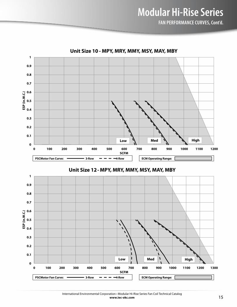
0
0.1
0.2
0.3
0.4
0.5
0.6
0.7
0.8
0.9
1
0 100 200 300 400 500 600 700 800 900 1000 1100 1200
ESP
(in.W
.C.)
SCFM
Unit Size 10 - MPY, MRY, MMY, MSY, MAY, MBY
PSC Motor Fan Curve: 3-Row 4-Row ECM Operating Range:
Low Med High
0
0.1
0.2
0.3
0.4
0.5
0.6
0.7
0.8
0.9
1
0 100 200 300 400 500 600 700 800 900 1000 1100 1200 1300
ESP
(in.W
.C.)
SCFM
Unit Size 12 - MPY, MRY, MMY, MSY, MAY, MBY
PSC Motor Fan Curve: 3-Row 4-Row ECM Operating Range:
Low Med High
FAN PERFORMANCE CURVES, Cont’d.
International Environmental Corporation • Modular Hi-Rise Series Fan Coil Technical Catalogwww.iec-okc.com16
Modular Hi-Rise SeriesELECTRIC HEATING
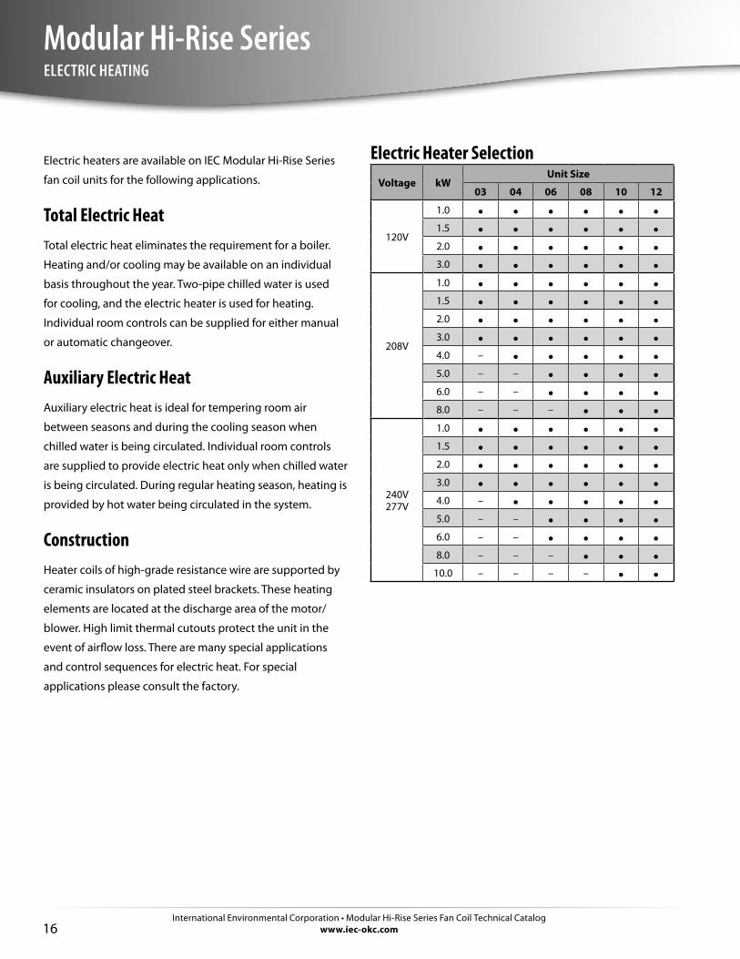
Electric heaters are available on IEC Modular Hi-Rise Series
fan coil units for the following applications.
Total Electric HeatTotal electric heat eliminates the requirement for a boiler.
Heating and/or cooling may be available on an individual
basis throughout the year. Two-pipe chilled water is used
for cooling, and the electric heater is used for heating.
Individual room controls can be supplied for either manual
or automatic changeover.
Auxiliary Electric HeatAuxiliary electric heat is ideal for tempering room air
between seasons and during the cooling season when
chilled water is being circulated. Individual room controls
are supplied to provide electric heat only when chilled water
is being circulated. During regular heating season, heating is
provided by hot water being circulated in the system.
ConstructionHeater coils of high-grade resistance wire are supported by
ceramic insulators on plated steel brackets. These heating
elements are located at the discharge area of the motor/
blower. High limit thermal cutouts protect the unit in the
event of airflow loss. There are many special applications
and control sequences for electric heat. For special
applications please consult the factory.
Electric Heater SelectionVoltage kW
Unit Size
03 04 06 08 10 12
120V
1.0 • • • • • •1.5 • • • • • •2.0 • • • • • •3.0 • • • • • •
208V
1.0 • • • • • •1.5 • • • • • •2.0 • • • • • •3.0 • • • • • •4.0 – • • • • •5.0 – – • • • •6.0 – – • • • •8.0 – – – • • •
240V277V
1.0 • • • • • •1.5 • • • • • •2.0 • • • • • •3.0 • • • • • •4.0 – • • • • •5.0 – – • • • •6.0 – – • • • •8.0 – – – • • •
10.0 – – – – • •
International Environmental Corporation • Modular Hi-Rise Series Fan Coil Technical Catalogwww.iec-okc.com
Modular Hi-Rise Series
17
MOTOR DATA
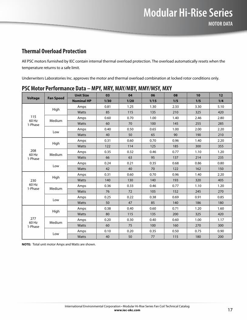
Thermal Overload ProtectionAll PSC motors furnished by IEC contain internal thermal overload protection. The overload automatically resets when the
temperature returns to a safe limit.
Underwriters Laboratories Inc. approves the motor and thermal overload combination at locked rotor conditions only.
PSC Motor Performance Data – MPY, MRY, MAY/MBY, MMY/MSY, MXYVoltage Fan Speed
Unit Size 03 04 06 08 10 12Nominal HP 1/30 1/20 1/15 1/5 1/5 1/4
115 60 Hz
1-Phase
HighAmps 0.81 1.25 1.30 2.33 3.30 5.10
Watts 85 115 135 210 325 420
MediumAmps 0.60 0.70 1.00 1.40 2.46 2.80
Watts 60 70 100 145 255 285
LowAmps 0.40 0.50 0.65 1.00 2.00 2.20
Watts 40 50 65 90 190 210
20860 Hz
1-Phase
HighAmps 0.31 0.60 0.70 0.96 1.40 2.20
Watts 122 114 125 185 300 355
MediumAmps 0.35 0.32 0.46 0.77 1.10 1.20
Watts 66 63 95 137 214 235
LowAmps 0.24 0.21 0.35 0.68 0.86 0.80
Watts 42 40 70 122 162 150
23060 Hz
1-Phase
HighAmps 0.31 0.60 0.70 0.96 1.40 2.20
Watts 140 130 140 193 320 405
MediumAmps 0.36 0.33 0.46 0.77 1.10 1.20
Watts 76 72 105 152 245 270
LowAmps 0.25 0.22 0.38 0.69 0.91 0.85
Watts 50 47 85 140 186 180
27760 Hz
1-Phase
HighAmps 0.38 0.40 0.60 0.71 1.20 1.60
Watts 80 115 135 200 325 420
MediumAmps 0.20 0.30 0.40 0.60 1.00 1.17
Watts 60 75 100 160 270 300
LowAmps 0.10 0.20 0.35 0.50 0.75 0.90
Watts 40 50 77 115 180 200
NOTE: Total unit motor Amps and Watts are shown.
International Environmental Corporation • Modular Hi-Rise Series Fan Coil Technical Catalogwww.iec-okc.com18
Modular Hi-Rise SeriesSUBMITTAL DATA
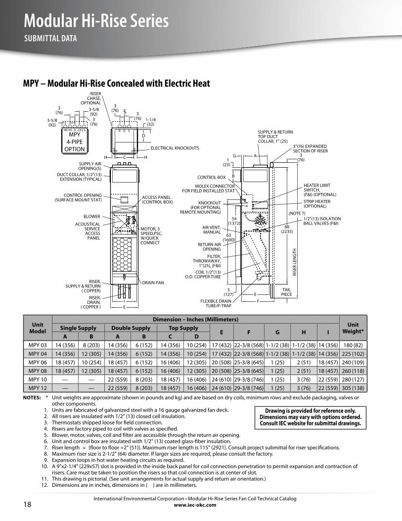
MPY – Modular Hi-Rise Concealed with Electric Heat
MPY4-PIPE
OPTION
MOTOR, 3SPEED,PSC,W/QUICKCONNECT
COIL 1/2"(13)O.D. COPPER TUBE
RISER,DRAIN,
( COPPER )
RISER,SUPPLY & RETURN
( COPPER)
CONTROL BOX
SUPPLY AIROPENING(S)
DUCT COLLAR, 1/2"(13)EXTENSION (TYPICAL)
CONTROL OPENING(SURFACE MOUNT STAT)
AIR VENT,MANUAL
RETURN AIROPENING
3"(76) EXPANDEDSECTION OF RISER
FILTER,THROWAWAY,
1"(25), (F&I)
FLEXIBLE DRAINTUBE/P-TRAP
BLOWER
DRAIN PAN
STRIP HEATER(OPTIONAL)
ACCESS PANEL(CONTROL BOX)
HEATER LIMITSWITCH,(F&I) (OPTIONAL)
RISERCHASE,
OPTIONAL
KNOCKOUT(FOR OPTIONAL
REMOTE MOUNTING)
MOLEX CONNECTORFOR FIELD INSTALLED STAT
ELECTRICAL KNOCKOUTS
1/2"(13) ISOLATIONBALL VALVES (F&I)ACOUSTICAL
SERVICE ACCESS
PANEL
SUPPLY & RETURNTOP DUCTCOLLAR, 1" (25)
CL
3(76)
88(2235)
TAILPIECE
5(127)
54(1372)
I
A
B
G
FRI
SER
LEN
GTH
D
1-1/4(32)
H C H
E
63(1600)
R D S
(NOTE 7)
HS D CRHR CS
3-5/8(92)
1(25)
3(76)
3(76)3
(76)3
(76)3-5/8(92)
E
Unit Model
Dimension – Inches (Millimeters)Unit
Weight*Single Supply Double Supply Top SupplyE F G H I
A B A B C DMPY 03 14 (356) 8 (203) 14 (356) 6 (152) 14 (356) 10 (254) 17 (432) 22-3/8 (568) 1-1/2 (38) 1-1/2 (38) 14 (356) 180 (82)MPY 04 14 (356) 12 (305) 14 (356) 6 (152) 14 (356) 10 (254) 17 (432) 22-3/8 (568) 1-1/2 (38) 1-1/2 (38) 14 (356) 225 (102)MPY 06 18 (457) 10 (254) 18 (457) 6 (152) 16 (406) 12 (305) 20 (508) 25-3/8 (645) 1 (25) 2 (51) 18 (457) 240 (109)MPY 08 18 (457) 12 (305) 18 (457) 6 (152) 16 (406) 12 (305) 20 (508) 25-3/8 (645) 1 (25) 2 (51) 18 (457) 260 (118)MPY 10 — — 22 (559) 8 (203) 18 (457) 16 (406) 24 (610) 29-3/8 (746) 1 (25) 3 (76) 22 (559) 280 (127)MPY 12 — — 22 (559) 8 (203) 18 (457) 16 (406) 24 (610) 29-3/8 (746) 1 (25) 3 (76) 22 (559) 305 (138)
NOTES: * Unit weights are approximate (shown in pounds and kg) and are based on dry coils, minimum rows and exclude packaging, valves or other components.
1. Units are fabricated of galvanized steel with a 16 gauge galvanized fan deck. 2. All risers are insulated with 1/2" (13) closed cell insulation. 3. Thermostats shipped loose for field connection. 4. Risers are factory piped to coil with valves as specified. 5. Blower, motor, valves, coil and filter are accessible through the return air opening. 6. Unit and control box are insulated with 1/2" (13) coated glass-fiber insulation. 7. Riser length = {floor to floor +2" (51)}. Maximum riser length is 115" (2921). Consult project submittal for riser specifications. 8. Maximum riser size is 2-1/2" (64) diameter. If larger sizes are required, please consult the factory. 9. Expansion loops in hot water heating circuits as required. 10. A 9"x2-1/4" (229x57) slot is provided in the inside back panel for coil connection penetration to permit expansion and contraction of
risers. Care must be taken to position the risers so that coil connection is at center of slot. 11. This drawing is pictorial. (See unit arrangements for actual supply and return air orientation.) 12. Dimensions are in inches, dimensions in ( ) are in millimeters.
Drawing is provided for reference only. Dimensions may vary with options ordered. Consult IEC website for submittal drawings.
International Environmental Corporation • Modular Hi-Rise Series Fan Coil Technical Catalogwww.iec-okc.com
Modular Hi-Rise Series
19
SUBMITTAL DATA, Cont’d.
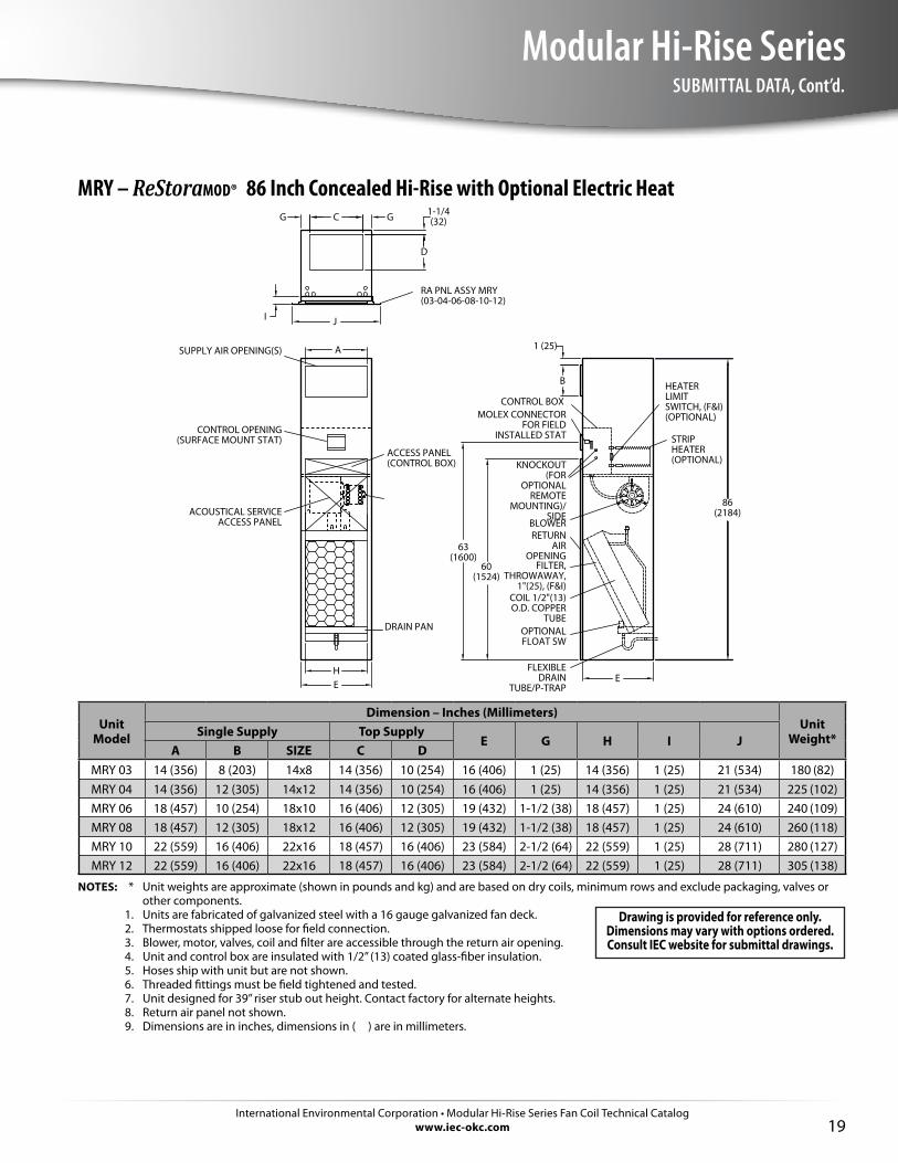
MRY – ReStoraMOD® 86 Inch Concealed Hi-Rise with Optional Electric Heat
COIL 1/2"(13)O.D. COPPER
TUBE
CONTROL BOX
SUPPLY AIR OPENING(S)
CONTROL OPENING (SURFACE MOUNT STAT)
RETURN AIR
OPENINGFILTER,
THROWAWAY, 1"(25), (F&I)
FLEXIBLE DRAIN
TUBE/P-TRAP
BLOWER
DRAIN PAN
STRIP HEATER (OPTIONAL)
ACCESS PANEL (CONTROL BOX)
HEATERLIMIT SWITCH, (F&I) (OPTIONAL)
KNOCKOUT (FOR
OPTIONAL REMOTE
MOUNTING)/SIDE
MOLEX CONNECTOR FOR FIELD
INSTALLED STAT
ACOUSTICAL SERVICE ACCESS PANEL
OPTIONALFLOAT SW
RA PNL ASSY MRY(03-04-06-08-10-12)
86(2184)
HE
B
D
1-1/4(32)
E
63(1600)
1 (25)
G C G
60(1524)
JI
A
Unit Model
Dimension – Inches (Millimeters)Unit
Weight*Single Supply Top SupplyE G H I J
A B SIZE C DMRY 03 14 (356) 8 (203) 14x8 14 (356) 10 (254) 16 (406) 1 (25) 14 (356) 1 (25) 21 (534) 180 (82)MRY 04 14 (356) 12 (305) 14x12 14 (356) 10 (254) 16 (406) 1 (25) 14 (356) 1 (25) 21 (534) 225 (102)MRY 06 18 (457) 10 (254) 18x10 16 (406) 12 (305) 19 (432) 1-1/2 (38) 18 (457) 1 (25) 24 (610) 240 (109)MRY 08 18 (457) 12 (305) 18x12 16 (406) 12 (305) 19 (432) 1-1/2 (38) 18 (457) 1 (25) 24 (610) 260 (118)MRY 10 22 (559) 16 (406) 22x16 18 (457) 16 (406) 23 (584) 2-1/2 (64) 22 (559) 1 (25) 28 (711) 280 (127)MRY 12 22 (559) 16 (406) 22x16 18 (457) 16 (406) 23 (584) 2-1/2 (64) 22 (559) 1 (25) 28 (711) 305 (138)
NOTES: * Unit weights are approximate (shown in pounds and kg) and are based on dry coils, minimum rows and exclude packaging, valves or other components.
1. Units are fabricated of galvanized steel with a 16 gauge galvanized fan deck. 2. Thermostats shipped loose for field connection. 3. Blower, motor, valves, coil and filter are accessible through the return air opening. 4. Unit and control box are insulated with 1/2” (13) coated glass-fiber insulation. 5. Hoses ship with unit but are not shown. 6. Threaded fittings must be field tightened and tested. 7. Unit designed for 39” riser stub out height. Contact factory for alternate heights. 8. Return air panel not shown. 9. Dimensions are in inches, dimensions in ( ) are in millimeters.
Drawing is provided for reference only. Dimensions may vary with options ordered. Consult IEC website for submittal drawings.
International Environmental Corporation • Modular Hi-Rise Series Fan Coil Technical Catalogwww.iec-okc.com20
Modular Hi-Rise SeriesSUBMITTAL DATA, Cont’d.
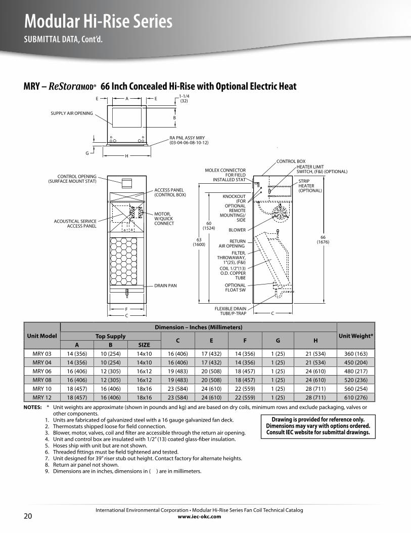
MRY – ReStoraMOD® 66 Inch Concealed Hi-Rise with Optional Electric Heat
MOTOR, W/QUICK CONNECT
COIL 1/2"(13) O.D. COPPER
TUBE
CONTROL BOX
SUPPLY AIR OPENING
CONTROL OPENING (SURFACE MOUNT STAT)
RETURN AIR OPENING
FILTER, THROWAWAY,
1"(25), (F&I)
FLEXIBLE DRAIN TUBE/P-TRAP
BLOWER
DRAIN PAN
STRIPHEATER (OPTIONAL)ACCESS PANEL
(CONTROL BOX)
HEATER LIMIT SWITCH, (F&I) (OPTIONAL)
KNOCKOUT (FOR
OPTIONAL REMOTE
MOUNTING)/SIDE
MOLEX CONNECTOR FOR FIELD
INSTALLED STAT
ACOUSTICAL SERVICE ACCESS PANEL
OPTIONAL FLOAT SW
RA PNL ASSY MRY (03-04-06-08-10-12)
66(1676)
FC
B
1-1/4(32)
C
63(1600)
E A E
60(1524)
HG
Unit ModelDimension – Inches (Millimeters)
Unit Weight*Top SupplyC E F G H
A B SIZEMRY 03 14 (356) 10 (254) 14x10 16 (406) 17 (432) 14 (356) 1 (25) 21 (534) 360 (163)MRY 04 14 (356) 10 (254) 14x10 16 (406) 17 (432) 14 (356) 1 (25) 21 (534) 450 (204)MRY 06 16 (406) 12 (305) 16x12 19 (483) 20 (508) 18 (457) 1 (25) 24 (610) 480 (217)MRY 08 16 (406) 12 (305) 16x12 19 (483) 20 (508) 18 (457) 1 (25) 24 (610) 520 (236)MRY 10 18 (457) 16 (406) 18x16 23 (584) 24 (610) 22 (559) 1 (25) 28 (711) 560 (254)MRY 12 18 (457) 16 (406) 18x16 23 (584) 24 (610) 22 (559) 1 (25) 28 (711) 610 (276)
NOTES: * Unit weights are approximate (shown in pounds and kg) and are based on dry coils, minimum rows and exclude packaging, valves or other components.
1. Units are fabricated of galvanized steel with a 16 gauge galvanized fan deck. 2. Thermostats shipped loose for field connection. 3. Blower, motor, valves, coil and filter are accessible through the return air opening. 4. Unit and control box are insulated with 1/2” (13) coated glass-fiber insulation. 5. Hoses ship with unit but are not shown. 6. Threaded fittings must be field tightened and tested. 7. Unit designed for 39” riser stub out height. Contact factory for alternate heights. 8. Return air panel not shown. 9. Dimensions are in inches, dimensions in ( ) are in millimeters.
Drawing is provided for reference only. Dimensions may vary with options ordered. Consult IEC website for submittal drawings.
International Environmental Corporation • Modular Hi-Rise Series Fan Coil Technical Catalogwww.iec-okc.com
Modular Hi-Rise Series
21
SUBMITTAL DATA, Cont’d.
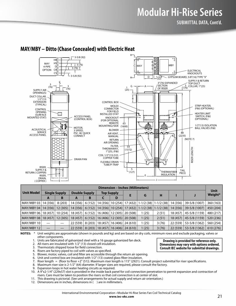
MAY/MBY – Ditto (Chase Concealed) with Electric Heat
RISER, DRAIN,
( COPPER )
MOTOR, 3 SPEED, PSC, W/ QUICK CONNECT
RISER, SUPPLY &
RETURN ( COPPER)
DUCT COLLAR, 1/2"(13)
EXTENSION (TYPICAL)
CONTROL OPENING
(SURFACE MOUNTED STAT)
FLEXIBLE DRAIN TUBE/P-TRAP
FILTER, THROWAWAY,
1"(25), (F&I)
ACCESS PANEL(CONTROL BOX) KNOCKOUT
(FOR OPTIONAL REMOTE
MOUNTING)/SIDE
MOLEX CONNECTOR
FOR FIELD INSTALLED STAT
GYPSUM BOARD, 5/8"(16) TYPE "X"
HEATER LIMIT SWITCH, (F&I) (OPTIONAL)
STRIP HEATER, (F&I) (OPTIONAL)
63(1600)
54(1372)
IE
RISE
R LE
NG
TH
ELECTRICAL KNOCKOUTS
ETHERMAFIBER INSULATION
DRAIN PAN
BLOWER
CONTROL BOX
SUPPLY AIR OPENING(S)
3"(76) EXPANDEDSECTION OF RISER
AIR VENT, MANUAL
RETURN AIR OPENING
COIL 1/2"(13) O.D. COPPER TUBE
3(76) 3
(76)
LC
SDR
3(76)
88(2235)
TAILPIECE
J
OPTION4-PIPE
3-5/8 (92)
MAY MBYMAY
HRHS
CRCS
D
(NOTE 7)
1/2"(13) ISOLATIONBALL VALVES (F&I)ACOUSTICAL
SERVICE ACCESS PANEL
3 (76)3 (76)
G A1(25)
B
H
H
C
D 1-1/4(32)
SUPPLY & RETURNTOP DUCT COLLAR, 1"(25)
5(127)
3-5/8 (92)
Unit ModelDimension – Inches (Millimeters)
Unit Weight*Single Supply Double Supply Top Supply
E G H I JA B A B C D
MAY/MBY 03 14 (356) 8 (203) 14 (356) 6 (152) 14 (356) 10 (254) 17 (432) 1-1/2 (38) 1-1/2 (38) 14 (356) 39-5/8 (1007) 360 (163)MAY/MBY 04 14 (356) 12 (305) 14 (356) 6 (152) 14 (356) 10 (254) 17 (432) 1-1/2 (38) 1-1/2 (38) 14 (356) 39-5/8 (1007) 450 (204)MAY/MBY 06 18 (457) 10 (254) 18 (457) 6 (152) 16 (406) 12 (305) 20 (508) 1 (25) 2 (51) 18 (457) 45-5/8 (1159) 480 (217)MAY/MBY 08 18 (457) 12 (305) 18 (457) 6 (152) 16 (406) 12 (305) 20 (508) 1 (25) 2 (51) 18 (457) 45-5/8 (1159) 520 (236)MAY/MBY 10 — — 22 (559) 8 (203) 18 (457) 16 (406) 24 (610) 1 (25) 3 (76) 22 (559) 53-5/8 (1362) 560 (254)MAY/MBY 12 — — 22 (559) 8 (203) 18 (457) 16 (406) 24 (610) 1 (25) 3 (76) 22 (559) 53-5/8 (1362) 610 (276)
NOTES: * Unit weights are approximate (shown in pounds and kg) and are based on dry coils, minimum rows and exclude packaging, valves or other components.
1. Units are fabricated of galvanized steel with a 16 gauge galvanized fan deck. 2. All risers are insulated with 1/2" (13) closed cell insulation. 3. Thermostats shipped loose for field connection. 4. Risers are factory piped to coil with valves as specified. 5. Blower, motor, valves, coil and filter are accessible through the return air opening. 6. Unit and control box are insulated with 1/2" (13) coated glass-fiber insulation. 7. Riser length = {floor to floor +2" (51)}. Maximum riser length is 115" (2921). Consult project submittal for riser specifications. 8. Maximum riser size is 2-1/2" (64) diameter. If larger sizes are required, please consult the factory. 9. Expansion loops in hot water heating circuits as required. 10. A 9"x2-1/4" (229x57) slot is provided in the inside back panel for coil connection penetration to permit expansion and contraction of
risers. Care must be taken to position the risers so that coil connection is at center of slot. 11. This drawing is pictorial. (See unit arrangements for actual supply and return air orientation.) 12. Dimensions are in inches, dimensions in ( ) are in millimeters.
Drawing is provided for reference only. Dimensions may vary with options ordered. Consult IEC website for submittal drawings.
International Environmental Corporation • Modular Hi-Rise Series Fan Coil Technical Catalogwww.iec-okc.com22
Modular Hi-Rise SeriesSUBMITTAL DATA, Cont’d.
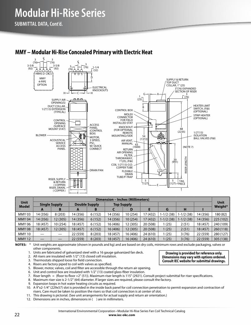
MMY – Modular Hi-Rise Concealed Primary with Electric Heat
3(76)
54(1372)
IE
A
B
G
RISE
R LE
NG
TH
D
1-1/4(32)
H C H
E
63(1600)
R D S
CL
88(2235)
TAILPIECE
(NOTE 7)
39
3(76)
HR
OPTION4-PIPEMMY
3(76)
HS D CSCR
3-5/8(92)
3-5/8(92)
(991)
AIR VENT, MANUAL
BLOWER
DRAIN PAN
CL
5(127)
5(127)
1(25)
3(76)
3(76)
CONTROL BOX
MOTOR, 3 SPEED, PSC, W/ QUICK CONNECT
COIL 1/2"(13) O.D.COPPER TUBE
RISER, DRAIN, ( COPPER )
RISER, SUPPLY & RETURN ( COPPER)
SUPPLY AIR OPENING(S)
DUCT COLLAR,1/2"(13) EXTENSION
(TYPICAL)
CONTROL OPENING
(SURFACE MOUNT STAT)
RETURN AIR OPENING
3"(76) EXPANDEDSECTION OF RISER
FILTER, THROWAWAY,
1"(25), (F&I)
FLEXIBLE DRAIN
TUBE/P-TRAP
STRIP HEATER (OPTIONAL)
ACCESS PANEL (CONTROL BOX)
HEATER LIMIT SWITCH, (F&I) (OPTIONAL)
KNOCKOUT(FOR OPTIONAL
REMOTEMOUNTING)/SIDE
MOLEX CONNECTOR
FOR FIELD INSTALLED STAT
ELECTRICALKNOCKOUTS
1/2"(13) ISOLATION BALL VALVES (F&I)
ACOUSTICAL SERVICE ACCESS
PANEL
SUPPLY & RETURNTOP DUCT COLLAR, 1" (25)
Unit Model
Dimension – Inches (Millimeters)Unit
Weight*Single Supply Double Supply Top SupplyA B A B C D E G H I
MMY 03 14 (356) 8 (203) 14 (356) 6 (152) 14 (356) 10 (254) 17 (432) 1-1/2 (38) 1-1/2 (38) 14 (356) 180 (82)MMY 04 14 (356) 12 (305) 14 (356) 6 (152) 14 (356) 10 (254) 17 (432) 1-1/2 (38) 1-1/2 (38) 14 (356) 225 (102)MMY 06 18 (457) 10 (254) 18 (457) 6 (152) 16 (406) 12 (305) 20 (508) 1 (25) 2 (51) 18 (457) 240 (109)MMY 08 18 (457) 12 (305) 18 (457) 6 (152) 16 (406) 12 (305) 20 (508) 1 (25) 2 (51) 18 (457) 260 (118)MMY 10 — — 22 (559) 8 (203) 18 (457) 16 (406) 24 (610) 1 (25) 3 (76) 22 (559) 280 (127)MMY 12 — — 22 (559) 8 (203) 18 (457) 16 (406) 24 (610) 1 (25) 3 (76) 22 (559) 305 (138)
NOTES: * Unit weights are approximate (shown in pounds and kg) and are based on dry coils, minimum rows and exclude packaging, valves or other components.
1. Units are fabricated of galvanized steel with a 16 gauge galvanized fan deck. 2. All risers are insulated with 1/2" (13) closed cell insulation. 3. Thermostats shipped loose for field connection. 4. Risers are factory piped to coil with valves as specified. 5. Blower, motor, valves, coil and filter are accessible through the return air opening. 6. Unit and control box are insulated with 1/2" (13) coated glass-fiber insulation. 7. Riser length = {floor to floor +2" (51)}. Maximum riser length is 115" (2921). Consult project submittal for riser specifications. 8. Maximum riser size is 2-1/2" (64) diameter. If larger sizes are required, please consult the factory. 9. Expansion loops in hot water heating circuits as required. 10. A 9"x2-1/4" (229x57) slot is provided in the inside back panel for coil connection penetration to permit expansion and contraction of
risers. Care must be taken to position the risers so that coil connection is at center of slot. 11. This drawing is pictorial. (See unit arrangements for actual supply and return air orientation.) 12. Dimensions are in inches, dimensions in ( ) are in millimeters.
Drawing is provided for reference only. Dimensions may vary with options ordered. Consult IEC website for submittal drawings.
International Environmental Corporation • Modular Hi-Rise Series Fan Coil Technical Catalogwww.iec-okc.com
Modular Hi-Rise Series
23
SUBMITTAL DATA, Cont’d.
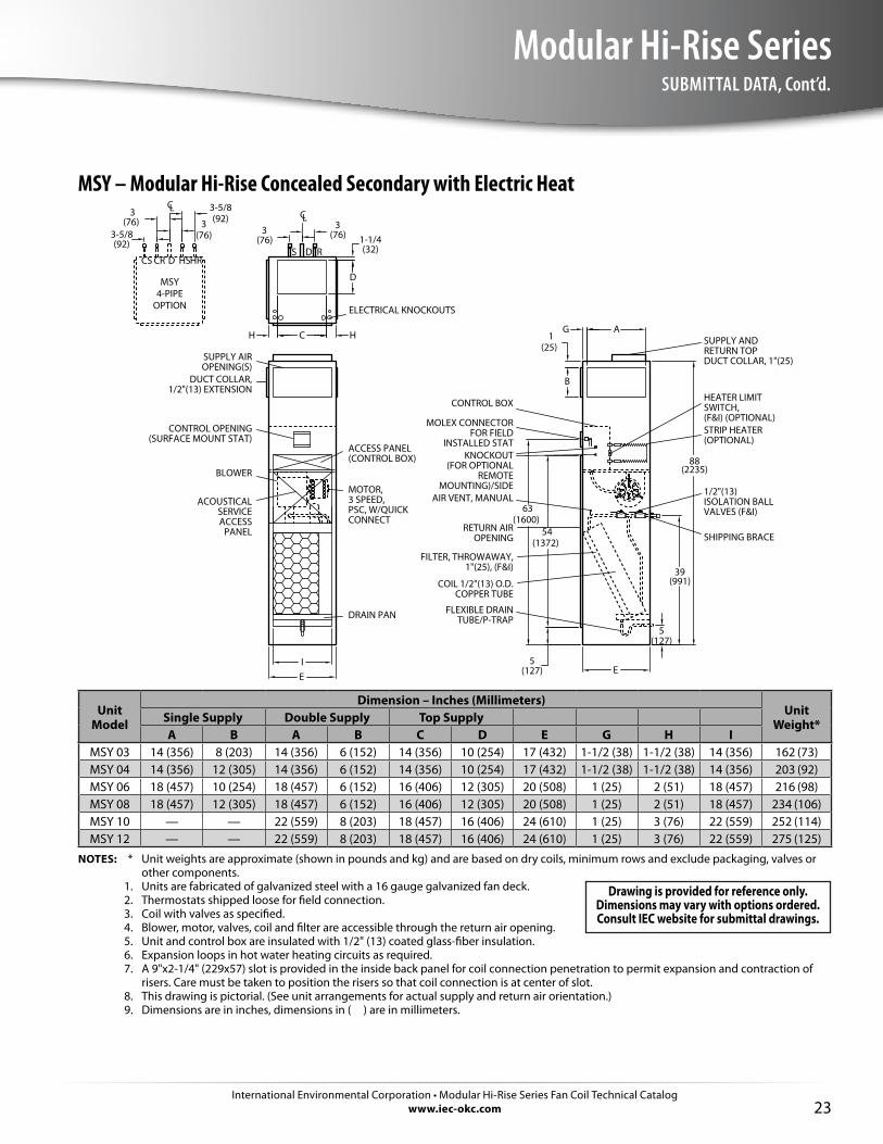
MSY – Modular Hi-Rise Concealed Secondary with Electric Heat
63(1600)
G
B
54(1372)
5(127)E
I
HCH
3(76)
3(76)
L
DS
C
1-1/4(32)
D
R
SHIPPING BRACE
ELECTRICAL KNOCKOUTS
MOLEX CONNECTOR FOR FIELD
INSTALLED STATKNOCKOUT
(FOR OPTIONAL REMOTE
MOUNTING)/SIDE
HEATER LIMIT SWITCH, (F&I) (OPTIONAL)
ACCESS PANEL(CONTROL BOX)
STRIP HEATER (OPTIONAL)
FLEXIBLE DRAIN TUBE/P-TRAP
FILTER, THROWAWAY, 1"(25), (F&I)
RETURN AIR OPENING
AIR VENT, MANUAL
CONTROL OPENING (SURFACE MOUNT STAT)
DUCT COLLAR, 1/2"(13) EXTENSION
SUPPLY AIR OPENING(S)
CONTROL BOX
COIL 1/2"(13) O.D. COPPER TUBE
MOTOR,3 SPEED, PSC, W/QUICK CONNECT
E
39
DRAIN PAN
BLOWER
A
3(76)
CS
OPTION4-PIPEMSY
3(76)
CR D HRHS
3-5/8(92)
3-5/8(92)
1/2"(13) ISOLATION BALL VALVES (F&I)
88
ACOUSTICAL SERVICE ACCESS
PANEL
SUPPLY AND RETURN TOP DUCT COLLAR, 1"(25)
(2235)
(991)
5(127)
LC
1(25)
Unit Model
Dimension – Inches (Millimeters)Unit
Weight*Single Supply Double Supply Top SupplyA B A B C D E G H I
MSY 03 14 (356) 8 (203) 14 (356) 6 (152) 14 (356) 10 (254) 17 (432) 1-1/2 (38) 1-1/2 (38) 14 (356) 162 (73)MSY 04 14 (356) 12 (305) 14 (356) 6 (152) 14 (356) 10 (254) 17 (432) 1-1/2 (38) 1-1/2 (38) 14 (356) 203 (92)MSY 06 18 (457) 10 (254) 18 (457) 6 (152) 16 (406) 12 (305) 20 (508) 1 (25) 2 (51) 18 (457) 216 (98)MSY 08 18 (457) 12 (305) 18 (457) 6 (152) 16 (406) 12 (305) 20 (508) 1 (25) 2 (51) 18 (457) 234 (106)MSY 10 — — 22 (559) 8 (203) 18 (457) 16 (406) 24 (610) 1 (25) 3 (76) 22 (559) 252 (114)MSY 12 — — 22 (559) 8 (203) 18 (457) 16 (406) 24 (610) 1 (25) 3 (76) 22 (559) 275 (125)
NOTES: * Unit weights are approximate (shown in pounds and kg) and are based on dry coils, minimum rows and exclude packaging, valves or other components.
1. Units are fabricated of galvanized steel with a 16 gauge galvanized fan deck. 2. Thermostats shipped loose for field connection. 3. Coil with valves as specified. 4. Blower, motor, valves, coil and filter are accessible through the return air opening. 5. Unit and control box are insulated with 1/2" (13) coated glass-fiber insulation. 6. Expansion loops in hot water heating circuits as required. 7. A 9"x2-1/4" (229x57) slot is provided in the inside back panel for coil connection penetration to permit expansion and contraction of
risers. Care must be taken to position the risers so that coil connection is at center of slot. 8. This drawing is pictorial. (See unit arrangements for actual supply and return air orientation.) 9. Dimensions are in inches, dimensions in ( ) are in millimeters.
Drawing is provided for reference only. Dimensions may vary with options ordered. Consult IEC website for submittal drawings.
International Environmental Corporation • Modular Hi-Rise Series Fan Coil Technical Catalogwww.iec-okc.com24
Modular Hi-Rise SeriesSUBMITTAL DATA, Cont’d.
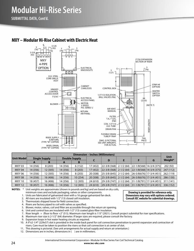
MXY – Modular Hi-Rise Cabinet with Electric Heat
DWG. IS PICTORALSEE UNIT ARRGMTS.
FOR ACTUAL
MXY4-PIPE
OPTION
HR HS D CSCR R D S
RISER, SUPPLY& RETURN,
(TYPE "M" COPPER)
D.D. STEELCORE GRILLE
ASSY
3"(76) EXPANSIONSECTION OF RISER
HINGEDCONTROL
ACCESS DOOR
FILTER,T.A, 1"(25),
(F&I)
FLEXIBLE DRAINTUBE/P-TRAP
RETURNAIR PANEL
STRIP HEATER(OPTIONAL)
ELECTRICALACCESS PANEL
HEATER LIMITSWITCH, (F&I)(OPTIONAL)
ELECTRICALKNOCKOUTS
BLOWER
DRAIN PAN
AIR VENT,MANUAL
T'STAT
MOTOR,3 SPEED,PSC SERIES 'L'
RISER, DRAIN,(TYPE "M" COPPER)
COIL 1/2"(13)O.D. TUBE
CONTROL BOXCABINETCAMLOCKS
1/2"(13) ISOLATIONBALL VALVES (F&I)
CL
D
C
CG
F
E A
B
CL
88(2235)
3(76)
TAILPIECE
(NOTE 7)
RISE
R LE
NG
TH
3(76)
3-5/8(92)
5(127)
3(76)
3(76)
3(76)
3-5/8(92)
Unit ModelDimension – Inches (Millimeters)
Unit Weight*Single Supply Double Supply
C D E F GA B A B
MXY 03 14 (356) 8 (203) 14 (356) 6 (152) 17 (432) 22-3/8 (568) 2-1/2 (64) 22-1/8(568) 14-3/4 (375) 202 (92)MXY 04 14 (356) 12 (305) 14 (356) 8 (203) 17 (432) 22-3/8 (568) 2-1/2 (64) 22-1/8(568) 14-3/4 (375) 247 (112)MXY 06 14 (356) 12 (305) 14 (356) 8 (203) 20 (508) 25-3/8 (645) 2-1/2 (64) 26-5/8(676) 17-3/4 (451) 262 (119)MXY 08 14 (356) 16 (406) 14 (356) 10 (254) 20 (508) 25-3/8 (645) 2-1/2 (64) 26-5/8(676) 17-3/4 (451) 286 (130)MXY 10 18 (457) 16 (406) 14 (356) 12 (305) 24 (610) 29-3/8 (747) 2-1/2 (64) 31-1/8(791) 17-3/4 (451) 311 (141)MXY 12 18 (457) 16 (406) 14 (356) 12 (305) 24 (610) 29-3/8 (747) 2-1/2 (64) 31-1/8(791) 17-3/4 (451) 336 (152)
NOTES: * Unit weights are approximate (shown in pounds and kg) and are based on dry coils, minimum rows and exclude packaging, valves or other components.
1. Units are fabricated of galvanized steel with a 16 gauge galvanized fan deck. 2. All risers are insulated with 1/2” (13) closed cell insulation. 3. Thermostats shipped loose for field connection. 4. Risers are factory piped to coil with valves as specified. 5. Blower, motor, valves, coil and filter are accessible through the return air opening. 6. Unit and control box are insulated with 1/2" (13) coated glass-fiber insulation. 7. Riser length = {floor to floor +2" (51)}. Maximum riser length is 115" (2921). Consult project submittal for riser specifications. 8. Maximum riser size is 2-1/2" (64) diameter. If larger sizes are required, please consult the factory. 9. Expansion loops in hot water heating circuits as required. 10. A 9"x2-1/4" (229x57) slot is provided in the inside back panel for coil connection penetration to permit expansion and contraction of
risers. Care must be taken to position the risers so that coil connection is at center of slot. 11. This drawing is pictorial. (See unit arrangements for actual supply and return air orientation.) 12. Dimensions are in inches, dimensions in ( ) are in millimeters.
Drawing is provided for reference only. Dimensions may vary with options ordered. Consult IEC website for submittal drawings.
International Environmental Corporation • Modular Hi-Rise Series Fan Coil Technical Catalogwww.iec-okc.com
Modular Hi-Rise Series
25
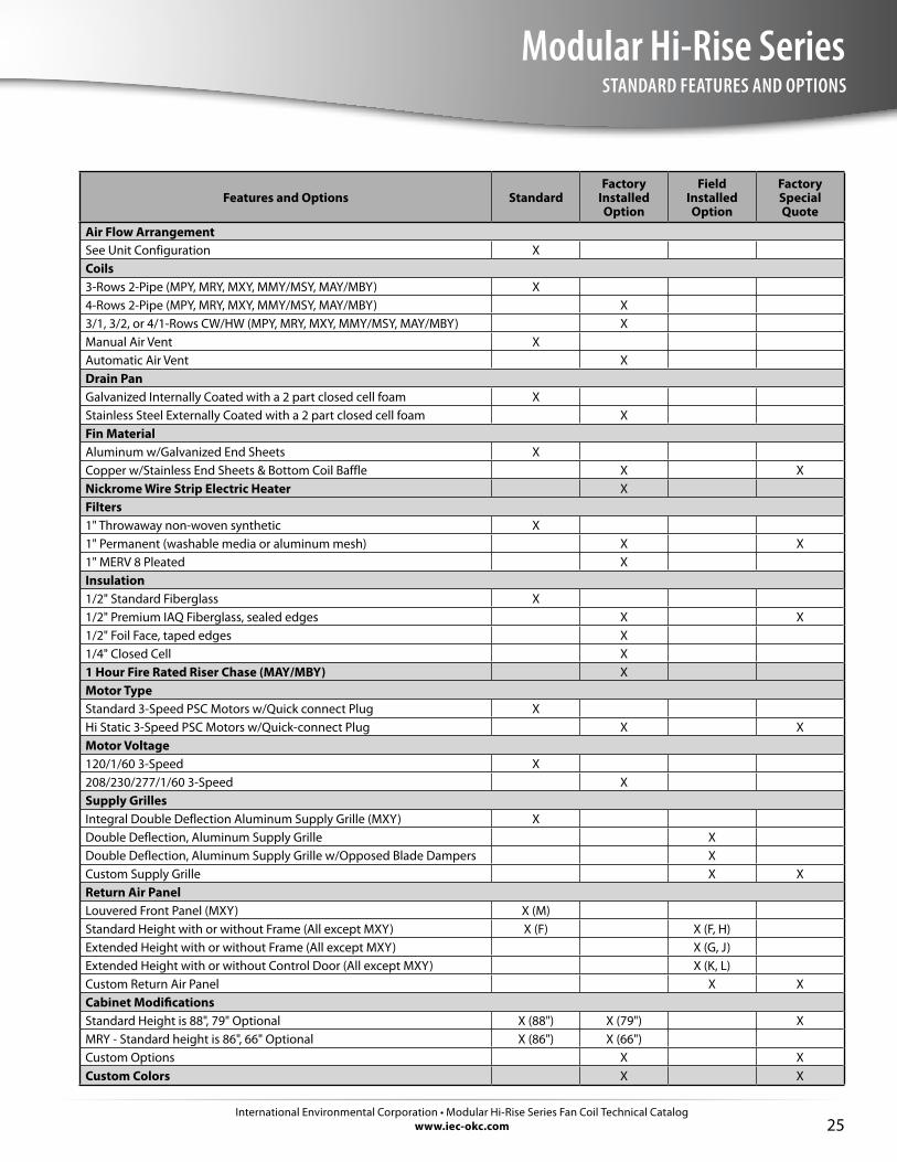
STANDARD FEATURES AND OPTIONS
Features and Options StandardFactory
Installed Option
Field Installed Option
Factory Special Quote
Air Flow ArrangementSee Unit Configuration XCoils3-Rows 2-Pipe (MPY, MRY, MXY, MMY/MSY, MAY/MBY) X4-Rows 2-Pipe (MPY, MRY, MXY, MMY/MSY, MAY/MBY) X3/1, 3/2, or 4/1-Rows CW/HW (MPY, MRY, MXY, MMY/MSY, MAY/MBY) XManual Air Vent XAutomatic Air Vent XDrain PanGalvanized Internally Coated with a 2 part closed cell foam XStainless Steel Externally Coated with a 2 part closed cell foam XFin MaterialAluminum w/Galvanized End Sheets XCopper w/Stainless End Sheets & Bottom Coil Baffle X XNickrome Wire Strip Electric Heater XFilters1" Throwaway non-woven synthetic X1" Permanent (washable media or aluminum mesh) X X1" MERV 8 Pleated XInsulation1/2" Standard Fiberglass X1/2" Premium IAQ Fiberglass, sealed edges X X1/2" Foil Face, taped edges X1/4" Closed Cell X1 Hour Fire Rated Riser Chase (MAY/MBY) XMotor TypeStandard 3-Speed PSC Motors w/Quick connect Plug XHi Static 3-Speed PSC Motors w/Quick-connect Plug X XMotor Voltage120/1/60 3-Speed X208/230/277/1/60 3-Speed XSupply GrillesIntegral Double Deflection Aluminum Supply Grille (MXY) XDouble Deflection, Aluminum Supply Grille XDouble Deflection, Aluminum Supply Grille w/Opposed Blade Dampers XCustom Supply Grille X XReturn Air PanelLouvered Front Panel (MXY) X (M)Standard Height with or without Frame (All except MXY) X (F) X (F, H)Extended Height with or without Frame (All except MXY) X (G, J)Extended Height with or without Control Door (All except MXY) X (K, L)Custom Return Air Panel X XCabinet ModificationsStandard Height is 88", 79" Optional X (88") X (79") XMRY - Standard height is 86", 66" Optional X (86") X (66")Custom Options X XCustom Colors X X

International Environmental Corporation • Modular Hi-Rise Series Fan Coil Technical Catalogwww.iec-okc.com26
Modular Hi-Rise SeriesSTANDARD FEATURES AND OPTIONS, Cont’d.
Features and Options StandardFactory
Installed Option
Field Installed Option
Factory Special Quote
RisersRiser Factory Installed XRisers Shipped Loose X XFlex Hoses X X XRiser Length (to 115") X X (>115")Riser Diameter (3/4" to 2-1/2") X X (>2-1/2")Closed Cell Riser Insulation1/2" X X3/4" XFiberglass Riser Insulation1/2" X X1" X XRiser/Drain MaterialType M Copper X X XType L Copper X XRiser Extension (M or L) XControlsService Switch with Lockout Tabs XSingle Point Power Connection XIncoming Power Fusing X24 V Controls XCondensate Overflow Switch XThermostats X X Surface Mounted w/Tile Ring X Unit Mounted X Wall/Remote Mounted XSpecial Control (DDC) X XOutside Air DampersManual Controlled Damper XMotorized Controlled Damper X X
International Environmental Corporation • Modular Hi-Rise Series Fan Coil Technical Catalogwww.iec-okc.com
Modular Hi-Rise Series
27
STANDARD FEATURES AND OPTIONS, Cont’d.
As detailed in the table below, we offer a control for most of our customer’s needs. Additional controls and devices are available to meet even the most demanding operating logic.
3-speed Fan ControlAll of our basic control schemes utilize a 3-speed switch to modulate the cooling output, to maximize the percentage of latent heat removal, and to further minimize the sound level when maximum cooling or heating performance is not required.
Low Voltage Control (24 V)An optional low voltage control is available with all of our control schemes.
Condensate Overflow SwitchThis optional switch shuts down the unit when the water level in the drain pan reaches an unsafe level. Building code changes in much of our country may require this type of device.
Service SwitchesWe offer optional service switches for use by maintenance and service personnel.
FusingWe offer optional incoming power fusing as well as blower motor and control sub-fusing for units that use electric heat.
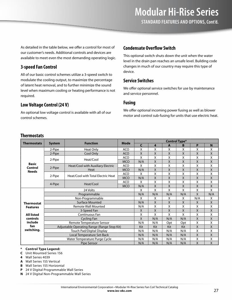
ThermostatsThermostats System Function Mode Control Type*
C 4 A B P N
BasicControl Needs
2-Pipe Heat Only ACO X X X X X X2-Pipe Cool Only ACO X X X X X X
2-Pipe Heat/Cool ACO X X X X X XMCO N/A X X X X X
2-Pipe Heat/Cool with Auxiliary Electric Heat
ACO X X X X X XMCO N/A X X X X X
2-Pipe Heat/Cool with Total Electric Heat ACO X X X X X XMCO N/A X X X X X
4-Pipe Heat/Cool ACO X X X X X XMCO N/A X X X X X
ThermostatFeatures
All listed controls include
fan switching.
24 Volts X X X X X XProgrammable N/A N/A N/A N/A X N/A
Non-Programmable X X X X N/A XSurface Mounted N/A X X X X X
Remote Wall Mounted N/A X X X X X3-Speed Fan X X X X X X
Continuous Fan X X X X X XCycling Fan X N/A N/A N/A X X
Remote Temperature Sensor N/A N/A Opt Opt X XAdjustable Operating Range (Range Stop Kit) Kit Kit Kit Kit X X
Touch Pad/Digital Display N/A N/A N/A N/A X XLocal Temperature Set-Back N/A N/A N/A N/A X X
Water Temperature Purge Cycle N/A N/A N/A N/A X XPipe Sensor N/A N/A N/A N/A X X
* Control Type Legend:C Unit Mounted Series 1564 Wall Series 4039A Wall Series 155 VerticalB Wall Series 155 HorizontalP 24 V Digital Programmable Wall SeriesN 24 V Digital Non-Programmable Wall Series
International Environmental Corporation • Modular Hi-Rise Series Fan Coil Technical Catalogwww.iec-okc.com28
Modular Hi-Rise SeriesSTANDARD FEATURES AND OPTIONS, Cont’d.
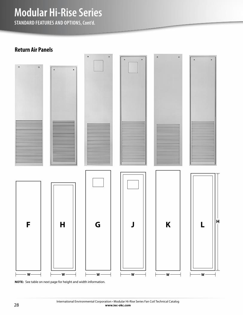
Return Air Panels
H
W
F
W
H
W
G
W
LK
W
J
W
NOTE: See table on next page for height and width information.
International Environmental Corporation • Modular Hi-Rise Series Fan Coil Technical Catalogwww.iec-okc.com
Modular Hi-Rise Series
29
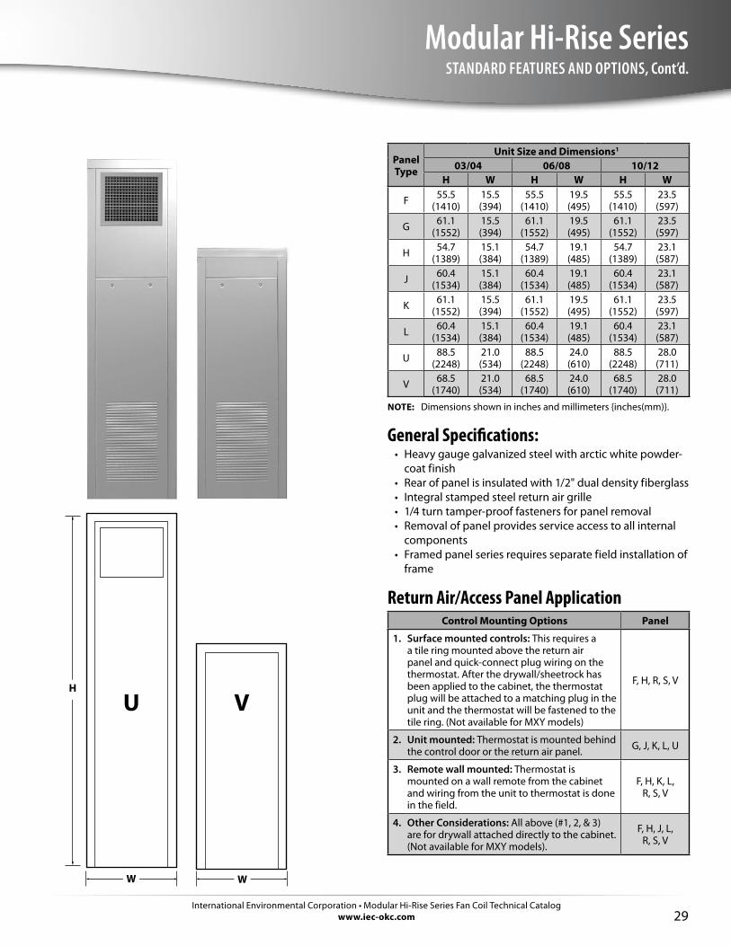
STANDARD FEATURES AND OPTIONS, Cont’d.
Panel Type
Unit Size and Dimensions1
03/04 06/08 10/12H W H W H W
F 55.5 (1410)
15.5 (394)
55.5 (1410)
19.5 (495)
55.5 (1410)
23.5 (597)
G 61.1 (1552)
15.5 (394)
61.1 (1552)
19.5 (495)
61.1 (1552)
23.5 (597)
H 54.7 (1389)
15.1 (384)
54.7 (1389)
19.1 (485)
54.7 (1389)
23.1 (587)
J 60.4 (1534)
15.1 (384)
60.4 (1534)
19.1 (485)
60.4 (1534)
23.1 (587)
K 61.1 (1552)
15.5 (394)
61.1 (1552)
19.5 (495)
61.1 (1552)
23.5 (597)
L 60.4 (1534)
15.1 (384)
60.4 (1534)
19.1 (485)
60.4 (1534)
23.1 (587)
U 88.5 (2248)
21.0 (534)
88.5 (2248)
24.0 (610)
88.5 (2248)
28.0 (711)
V 68.5 (1740)
21.0 (534)
68.5 (1740)
24.0 (610)
68.5 (1740)
28.0 (711)
NOTE: Dimensions shown in inches and millimeters {inches(mm)}.
General Specifications:• Heavy gauge galvanized steel with arctic white powder-
coat finish• Rear of panel is insulated with 1/2" dual density fiberglass• Integral stamped steel return air grille• 1/4 turn tamper-proof fasteners for panel removal• Removal of panel provides service access to all internal
components• Framed panel series requires separate field installation of
frame
Return Air/Access Panel ApplicationControl Mounting Options Panel
1. Surface mounted controls: This requires a a tile ring mounted above the return air panel and quick-connect plug wiring on the thermostat. After the drywall/sheetrock has been applied to the cabinet, the thermostat plug will be attached to a matching plug in the unit and the thermostat will be fastened to the tile ring. (Not available for MXY models)
F, H, R, S, V
2. Unit mounted: Thermostat is mounted behind the control door or the return air panel. G, J, K, L, U
3. Remote wall mounted: Thermostat is mounted on a wall remote from the cabinet and wiring from the unit to thermostat is done in the field.
F, H, K, L, R, S, V
4. Other Considerations: All above (#1, 2, & 3) are for drywall attached directly to the cabinet. (Not available for MXY models).
F, H, J, L, R, S, V
W
H
W
VU
International Environmental Corporation • Modular Hi-Rise Series Fan Coil Technical Catalogwww.iec-okc.com30
Modular Hi-Rise SeriesSTANDARD FEATURES AND OPTIONS, Cont’d.
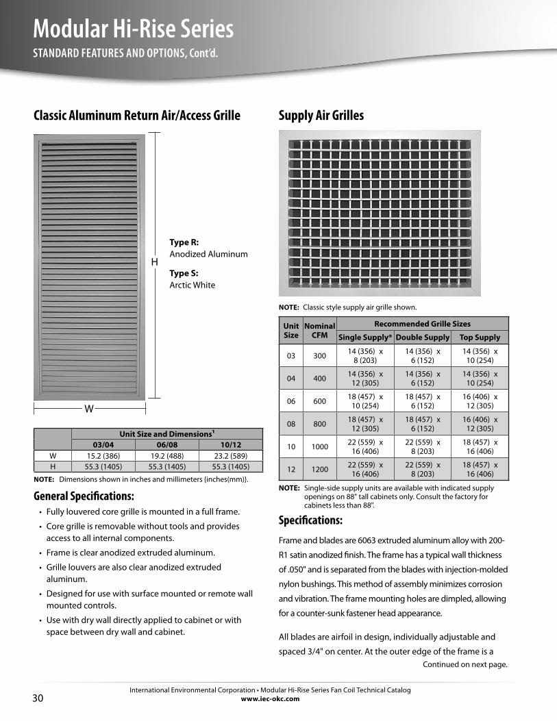
Supply Air Grilles
NOTE: Classic style supply air grille shown.
Unit Size
Nominal CFM
Recommended Grille Sizes
Single Supply* Double Supply Top Supply
03 300 14 (356) x 8 (203)
14 (356) x 6 (152)
14 (356) x 10 (254)
04 400 14 (356) x 12 (305)
14 (356) x 6 (152)
14 (356) x 10 (254)
06 600 18 (457) x 10 (254)
18 (457) x 6 (152)
16 (406) x 12 (305)
08 800 18 (457) x 12 (305)
18 (457) x 6 (152)
16 (406) x 12 (305)
10 1000 22 (559) x 16 (406)
22 (559) x 8 (203)
18 (457) x 16 (406)
12 1200 22 (559) x 16 (406)
22 (559) x 8 (203)
18 (457) x 16 (406)
NOTE: Single-side supply units are available with indicated supply openings on 88" tall cabinets only. Consult the factory for cabinets less than 88".
Specifications:Frame and blades are 6063 extruded aluminum alloy with 200-
R1 satin anodized finish. The frame has a typical wall thickness
of .050" and is separated from the blades with injection-molded
nylon bushings. This method of assembly minimizes corrosion
and vibration. The frame mounting holes are dimpled, allowing
for a counter-sunk fastener head appearance.
All blades are airfoil in design, individually adjustable and
spaced 3/4" on center. At the outer edge of the frame is a
Classic Aluminum Return Air/Access Grille
Unit Size and Dimensions¹03/04 06/08 10/12
W 15.2 (386) 19.2 (488) 23.2 (589)H 55.3 (1405) 55.3 (1405) 55.3 (1405)
NOTE: Dimensions shown in inches and millimeters {inches(mm)}.
General Specifications:• Fully louvered core grille is mounted in a full frame.
• Core grille is removable without tools and provides access to all internal components.
• Frame is clear anodized extruded aluminum.
• Grille louvers are also clear anodized extruded aluminum.
• Designed for use with surface mounted or remote wall mounted controls.
• Use with dry wall directly applied to cabinet or with space between dry wall and cabinet.
Type R: Anodized Aluminum
Type S: Arctic White
W
H
Continued on next page.
International Environmental Corporation • Modular Hi-Rise Series Fan Coil Technical Catalogwww.iec-okc.com
Modular Hi-Rise Series
31
STANDARD FEATURES AND OPTIONS, Cont’d.
specially engineered channel which retains an extruded
flexible vinyl bulb gasket that produces a positive air seal
at the mounting surface, minimizing smudging.
An optional opposed blade damper is screwdriver-
operated through the face of the unit and has the same
extruded aluminum construction and injection-molded
nylon bushings.
The unit achieves an effective area of 80% with the blades
set at a 0° pattern, thus eliminating high velocity and
pressure drop at the grille face. Wider deflection with
reduced throw may be achieved at the 22° and 45° blade
settings with slightly increased sound levels.
Suitable for sidewall application. Available in clear
anodized, white or a variety of custom colors. Contact the
factory for available optional colors and color chart.
FiltersUnit Size
Nominal 1" Filter Size
MPY, MAY/MBY, MMY/MSY, MXY MRY
03 12-1/2 (316) x 24-1/4 (616) 12-1/2 (316) x 24-1/4 (616)
04 12-1/2 (316) x 24-1/4 (616) 12-1/2 (316) x 24-1/4 (616)
06 16-1/4 (413) x 26-3/4 (679) 15-1/4 (387) x 26-3/4 (679)
08 16-1/4 (413) x 26-3/4 (679) 15-1/4 (387) x 26-3/4 (679)
10 20-1/2 (521) x 29-1/4 (743) 19-1/2 (495) x 29-1/4 (743)
12 20-1/2 (521) x 29-1/4 (743) 19-1/2 (495) x 29-1/4 (743)
NOTE: Sizes shown are nominal ordering sizes.

P.O. Box 2598Oklahoma City, OK 73101-2598
p: 405.605.5000f: 405.605.5001
www.iec-okc.com
IEC Catalog Part #: I100-90002105 CA-050 Revision 12
©2002-2016 International Environmental Corporation ReStoraMOD® patent pending


![Preparation, spectral characterization and antibacterial ...downloads.hindawi.com/journals/jspec/2008/170213.pdf · Silver(I) complexes of 2-mercaptopyridine (Mpy), [Ag(Mpy)]NO3 and](https://img.pdfslide.net/doc/110x75/60624f0612c8e33fb2601f91/preparation-spectral-characterization-and-antibacterial-silveri-complexes.jpg)