Embed Size (px)
Citation preview
365
Modular TypeFilter Regulators
Series AWFilter RegulatorSeries AW
Filter Regulator with Backflow FunctionSeries AW�K
Mist Separator RegulatorSeries AWM
Micro Mist Separator RegulatorSeries AWD
Model
Pages 366 through to 377
Pages 366 through to 377
Pages 378 through to 387
Pages 378 through to 387
Port size
M5 x 0.8
1/8, 1/4
1/4, 3/8
1/4, 3/8, 1/2
3/4
3/4, 1
1/8, 1/4
1/4, 3/8
1/4, 3/8, 1/2
3/4
3/4, 1
1/8, 1/4
1/4, 3/8
1/4, 3/8, 1/2
1/8, 1/4
1/4, 3/8
1/4, 3/8, 1/2
Options
Bracket
Float type auto drain
Square embedded type pressure gauge (except the AW10)
Round type pressure gauge
Digital pressure switch(except the AW10)
Panel mount
AW10
AW20
AW30
AW40
AW40-06
AW60
AWM20
AWM30
AWM40
AWD20
AWD30
AWD40
AW20K
AW30K
AW40K
AW40K-06
AW60K
AC
AF�
AR
AL
AW�
A�G
AVAF800AF900
P0365-P0446-E.qxd 08.11.6 2:09 PM Page 365
JIS SymbolFilter Regulator
Filter Regulator with Backflow Function
How to Order
AW 30 03 BEK • Option/Semi-standard: Select one each for a to i.• Option/Semi-standard symbol: When more
than one specification is required, indicate in alphanumeric order.
Example) AW30K-03BE-1N
Example) When the air supply is cut off and releasing the inlet pressure to the atmosphere, the residual pressure release of the outlet side can be ensured for a safety purpose.
• Integrated filter and regulator units save space and require less piping.• With the backflow function it incorporates a mechanism to exhaust the air pressure in
the outlet side reliably and quickly.
+
+
+
+
+
Body sizeDescription
Without backflow functionWith backflow function
Symbol
NilK Note 1)
NilE
G
ME1 Note 6)
E2 Note 6)
E3 Note 6)
E4 Note 6)
NilCD
Nil
N Note 2)
F Note 3)
With backflowfunction
Thread type
Pressuregauge
Digitalpressureswitch
Float typeauto drain
Metric thread (M5)Rc
NPTG
Without auto drainFloat type auto drain (N.C.)Float type auto drain (N.O.)
Without pressure gaugeSquare embedded type pressure gauge (with limit indicator)Round type pressure gauge (without limit indicator)Round type pressure gauge (with limit indicator)Round type pressure gauge (with color zone)Output: NPN output / Electrical entry: Wiring bottom entry Output: NPN output / Electrical entry: Wiring top entryOutput: PNP output / Electrical entry: Wiring bottom entry Output: PNP output / Electrical entry: Wiring top entry
M5010203040610
Port size
M51/81/43/81/23/41
c
b
10 20 30 40 60
NilB Note 5)
HMounting
Without mounting optionWith bracketWith set nut (for panel fitting)
a
+
+
Nil268C6C
Bowl Note 9)
Nil Note 7)
1 Note 8)Set pressure
Polycarbonate bowlMetal bowlNylon bowlMetal bowl with level gaugeWith bowl guardNylon bowl with bowl guard
0.05 to 0.85 MPa setting0.02 to 0.2 MPa setting
e
d
Made to OrderRefer to pages 374 throughto 377 for details.
Sem
i-sta
ndar
d
Note 4)
Opt
ion
366
Filter Regulator
AW10 to AW60Filter Regulator with Backflow Function
AW20K to AW60K
P0365-P0446-E.qxd 08.11.6 2:09 PM Page 366
367
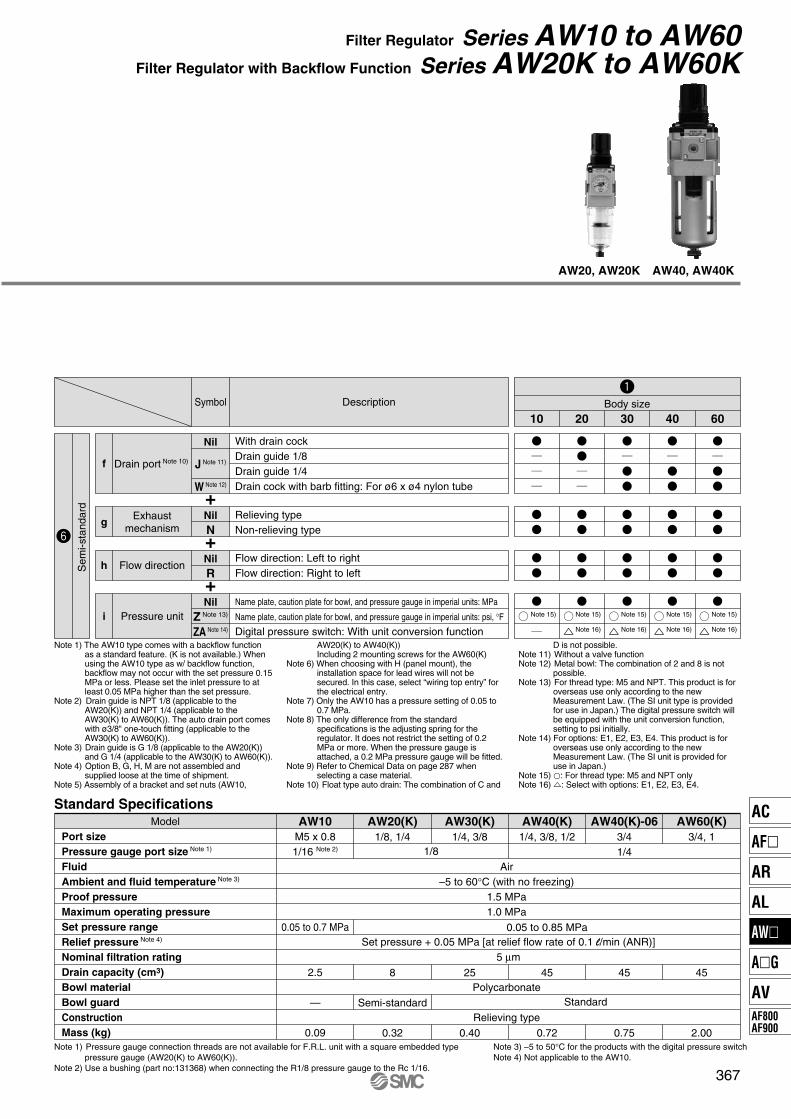
Filter Regulator Series AW10 to AW60Filter Regulator with Backflow Function Series AW20K to AW60K
ModelPort sizePressure gauge port size Note 1)
FluidAmbient and fluid temperature Note 3)
Proof pressureMaximum operating pressureSet pressure rangeRelief pressure Note 4)
Nominal filtration ratingDrain capacity (cm3)Bowl materialBowl guardConstructionMass (kg)
AW10M5 x 0.81/16 Note 2)
0.05 to 0.7 MPa
2.5
—
0.09
AW20(K)1/8, 1/4
8
Semi-standard
0.32
AW30(K)1/4, 3/8
25
0.40
AW40(K)1/4, 3/8, 1/2
0.05 to 0.85 MPa
45
0.72
AW40(K)-063/41/4
45
0.75
AW60(K)3/4, 1
45
2.00
1/8
Air–5 to 60°C (with no freezing)
1.5 MPa1.0 MPa
Polycarbonate
Relieving type
Set pressure + 0.05 MPa [at relief flow rate of 0.1 l/min (ANR)]5 μm
Standard
Note 1) Pressure gauge connection threads are not available for F.R.L. unit with a square embedded type pressure gauge (AW20(K) to AW60(K)).
Note 2) Use a bushing (part no:131368) when connecting the R1/8 pressure gauge to the Rc 1/16.
Note 3) –5 to 50°C for the products with the digital pressure switchNote 4) Not applicable to the AW10.
AW20, AW20K AW40, AW40K
Standard Specifications
+
+
+
NilN
NilR
Exhaustmechanism
Flow direction
NilZ Note 13)
ZA Note 14)
Pressure unit
Relieving typeNon-relieving type
Flow direction: Left to rightFlow direction: Right to left
Name plate, caution plate for bowl, and pressure gauge in imperial units: MPa
Name plate, caution plate for bowl, and pressure gauge in imperial units: psi, °FDigital pressure switch: With unit conversion function
g
h
i
Nil
J Note 11)
W Note 12)
Drain port Note 10)
With drain cockDrain guide 1/8Drain guide 1/4Drain cock with barb fitting: For ø6 x ø4 nylon tube
f
Body sizeDescriptionSymbol
Note 15) Note 15) Note 15) Note 15) Note 15)
Note 16) Note 16) Note 16) Note 16)
10 20 30 40 60
Note 1) The AW10 type comes with a backflow function as a standard feature. (K is not available.) When using the AW10 type as w/ backflow function, backflow may not occur with the set pressure 0.15 MPa or less. Please set the inlet pressure to at least 0.05 MPa higher than the set pressure.
Note 2) Drain guide is NPT 1/8 (applicable to the AW20(K)) and NPT 1/4 (applicable to the AW30(K) to AW60(K)). The auto drain port comes with ø3/8" one-touch fitting (applicable to the AW30(K) to AW60(K)).
Note 3) Drain guide is G 1/8 (applicable to the AW20(K)) and G 1/4 (applicable to the AW30(K) to AW60(K)).
Note 4) Option B, G, H, M are not assembled and supplied loose at the time of shipment.
Note 5) Assembly of a bracket and set nuts (AW10,
AW20(K) to AW40(K))Including 2 mounting screws for the AW60(K)
Note 6) When choosing with H (panel mount), the installation space for lead wires will not be secured. In this case, select “wiring top entry” for the electrical entry.
Note 7) Only the AW10 has a pressure setting of 0.05 to 0.7 MPa.
Note 8) The only difference from the standard specifications is the adjusting spring for the regulator. It does not restrict the setting of 0.2 MPa or more. When the pressure gauge is attached, a 0.2 MPa pressure gauge will be fitted.
Note 9) Refer to Chemical Data on page 287 when selecting a case material.
Note 10) Float type auto drain: The combination of C and
D is not possible.Note 11) Without a valve functionNote 12) Metal bowl: The combination of 2 and 8 is not
possible.Note 13) For thread type: M5 and NPT. This product is for
overseas use only according to the new Measurement Law. (The SI unit type is provided for use in Japan.) The digital pressure switch will be equipped with the unit conversion function, setting to psi initially.
Note 14) For options: E1, E2, E3, E4. This product is for overseas use only according to the new Measurement Law. (The SI unit is provided for use in Japan.)
Note 15) �: For thread type: M5 and NPT onlyNote 16) �: Select with options: E1, E2, E3, E4.
Sem
i-sta
ndar
d
AC
AF�
AR
AL
AW�
A�G
AVAF800AF900
P0365-P0446-E.qxd 08.11.6 2:09 PM Page 367
368
Series AW10 to AW60Series AW20K to AW60K
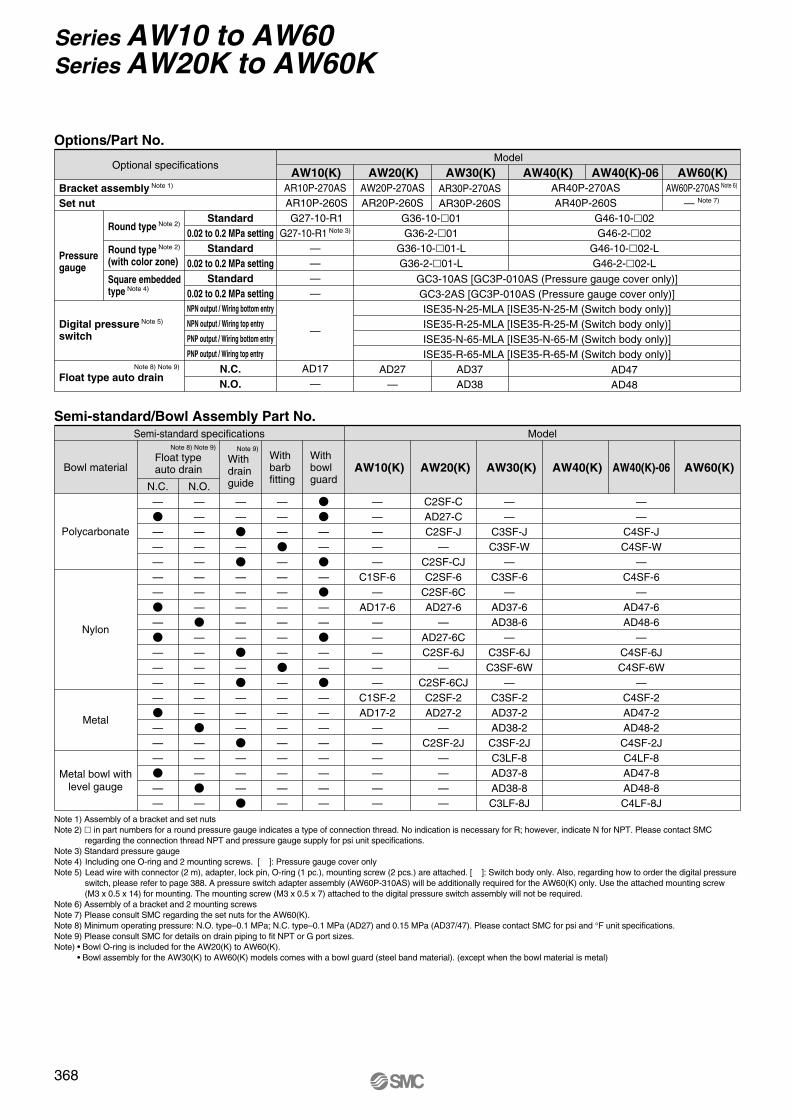
Options/Part No.Model
Optional specifications
Bracket assembly Note 1)
Set nut
Pressuregauge
Digital pressure Note 5) switch
Float type auto drain
Round type Note 2)Standard
0.02 to 0.2 MPa settingStandard
0.02 to 0.2 MPa settingStandard
0.02 to 0.2 MPa setting
N.C.N.O.
NPN output / Wiring bottom entry
NPN output / Wiring top entry
PNP output / Wiring bottom entry
PNP output / Wiring top entry
Square embedded type Note 4)
Round type Note 2)
(with color zone)
AR10P-270AS AR10P-260S G27-10-R1
G27-10-R1 Note 3)
————
AW10(K)AW20P-270ASAR20P-260S
AD17—
—
AD27—
AW20(K)AR30P-270ASAR30P-260S
AD37AD38
AW30(K)AR40P-270ASAR40P-260S
AW40(K)
G46-10-�02G46-2-�02
G46-10-�02-LG46-2-�02-L
AD47AD48
GC3-10AS [GC3P-010AS (Pressure gauge cover only)]GC3-2AS [GC3P-010AS (Pressure gauge cover only)]ISE35-N-25-MLA [ISE35-N-25-M (Switch body only)]ISE35-R-25-MLA [ISE35-R-25-M (Switch body only)]ISE35-N-65-MLA [ISE35-N-65-M (Switch body only)]ISE35-R-65-MLA [ISE35-R-65-M (Switch body only)]
G36-10-�01G36-2-�01
G36-10-�01-LG36-2-�01-L
AW40(K)-06AW60P-270AS Note 6)
— Note 7)
AW60(K)
Semi-standard/Bowl Assembly Part No.
Note 1) Assembly of a bracket and set nutsNote 2) � in part numbers for a round pressure gauge indicates a type of connection thread. No indication is necessary for R; however, indicate N for NPT. Please contact SMC
regarding the connection thread NPT and pressure gauge supply for psi unit specifications.Note 3) Standard pressure gauge Note 4) Including one O-ring and 2 mounting screws. [ ]: Pressure gauge cover onlyNote 5) Lead wire with connector (2 m), adapter, lock pin, O-ring (1 pc.), mounting screw (2 pcs.) are attached. [ ]: Switch body only. Also, regarding how to order the digital pressure
switch, please refer to page 388. A pressure switch adapter assembly (AW60P-310AS) will be additionally required for the AW60(K) only. Use the attached mounting screw (M3 x 0.5 x 14) for mounting. The mounting screw (M3 x 0.5 x 7) attached to the digital pressure switch assembly will not be required.
Note 6) Assembly of a bracket and 2 mounting screwsNote 7) Please consult SMC regarding the set nuts for the AW60(K).Note 8) Minimum operating pressure: N.O. type–0.1 MPa; N.C. type–0.1 MPa (AD27) and 0.15 MPa (AD37/47). Please contact SMC for psi and °F unit specifications.Note 9) Please consult SMC for details on drain piping to fit NPT or G port sizes.Note) • Bowl O-ring is included for the AW20(K) to AW60(K).
• Bowl assembly for the AW30(K) to AW60(K) models comes with a bowl guard (steel band material). (except when the bowl material is metal)
—
�—————
�—
�————
�———
�——
————————
�——————
�———
�—
——
�—
�—————
�—
�———
�———
�
———
�———————
�—————————
��——
�—
�——
�——
�————————
—————
C1SF-6—
AD17-6—————
C1SF-2AD17-2
——————
N.C. N.O.
ModelSemi-standard specifications
Withbowlguard
Withbarbfitting
Bowl material
Polycarbonate
Nylon
Metal
Metal bowl withlevel gauge
AW40(K)-06AW40(K)AW30(K)AW20(K)AW10(K)
C2SF-CAD27-CC2SF-J
—C2SF-CJC2SF-6
C2SF-6CAD27-6
—AD27-6CC2SF-6J
—C2SF-6CJ
C2SF-2AD27-2
—C2SF-2J
————
——
C3SF-JC3SF-W
—C3SF-6
—AD37-6AD38-6
—C3SF-6JC3SF-6W
—C3SF-2AD37-2AD38-2C3SF-2JC3LF-8AD37-8AD38-8C3LF-8J
——
C4SF-JC4SF-W
—C4SF-6
—AD47-6AD48-6
—C4SF-6JC4SF-6W
—C4SF-2AD47-2AD48-2C4SF-2JC4LF-8AD47-8AD48-8C4LF-8J
AW60(K)Withdrainguide
Note 9)
Float typeauto drain
Note 8) Note 9)
Note 8) Note 9)
P0365-P0446-E.qxd 08.11.6 2:09 PM Page 368
369
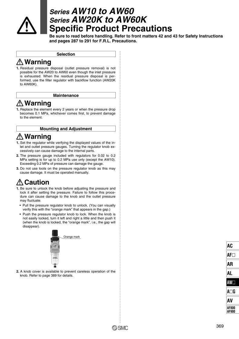
Series AW10 to AW60Series AW20K to AW60KSpecific Product PrecautionsBe sure to read before handling. Refer to front matters 42 and 43 for Safety Instructions and pages 287 to 291 for F.R.L. Precautions.
Orange mark
Selection
1. Residual pressure disposal (outlet pressure removal) is not possible for the AW20 to AW60 even though the inlet pressure is exhausted. When the residual pressure disposal is per-formed, use the filter regulator with backflow function (AW20K to AW60K).
Warning
Maintenance
1. Replace the element every 2 years or when the pressure drop becomes 0.1 MPa, whichever comes first, to prevent damage to the element.
Warning
Mounting and Adjustment
1. Set the regulator while verifying the displayed values of the in-let and outlet pressure gauges. Turning the regulator knob ex-cessively can cause damage to the internal parts.
2. The pressure gauge included with regulators for 0.02 to 0.2 MPa setting is for up to 0.2 MPa use only (except the AW10). Exceeding 0.2 MPa of pressure can damage the gauge.
3. Do not use tools on the pressure regulator knob as this may cause damage. It must be operated manually.
1. Be sure to unlock the knob before adjusting the pressure and lock it after setting the pressure. Failure to follow this proce-dure can cause damage to the knob and the outlet pressure may fluctuate.• Pull the pressure regulator knob to unlock. (You can visually
verify this with the “orange mark” that appears in the gap.)• Push the pressure regulator knob to lock. When the knob is
not easily locked, turn it left and right a little and then push it (when the knob is locked, the “orange mark”, i.e., the gap will disappear).
2. A knob cover is available to prevent careless operation of the knob. Refer to page 389 for details.
Caution
Warning
AC
AF�
AR
AL
AW�
A�G
AVAF800AF900
P0365-P0446-E.qxd 08.11.6 2:09 PM Page 369
370
Series AW10 to AW60Series AW20K to AW60K
0.6
0.5
0.4
0.3
0.2
0.1
03000 40001000 2000
AW40(K)-06 Rc 3/4
Flow rate (l/min (ANR))
Out
let p
ress
ure
(MP
a)
0
0.6
0.5
0.4
0.3
0.2
0.1
02000
AW40(K) Rc 1/2
Flow rate (l/min (ANR))
Out
let p
ress
ure
(MP
a)
0 1000 3000
0.6
0.5
0.4
0.3
0.2
0.1
00 5000 10000
AW60(K) Rc 1
Flow rate (l/min (ANR))
Out
let p
ress
ure
(MP
a)
AW20(K) Rc 1/40.6
0.5
0.4
0.3
0.2
0.1
0600 800400200
Flow rate (l/min (ANR))
Out
let p
ress
ure
(MP
a)
0
Rc 3/8AW30(K)
Out
let p
ress
ure
(MP
a)
0.6
0.5
0.4
0.3
0.2
0.1
01000
Flow rate (l/min (ANR))0 500 1500
Out
let p
ress
ure
(MP
a)
0.6
0.5
0.4
0.3
0.2
0.1
0150125100755025
AW10
Flow rate (l/min (ANR))0
M5
Out
let p
ress
ure
(MP
a)
0.25
0.2
0.15
010.90.80.70.60.50.40.30.2
AW30(K)
Inlet pressure (MPa)0
Set point
AW40(K)-06
Out
let p
ress
ure
(MP
a)
0.25
0.2
0.15
010.90.80.70.60.50.40.30.2
Inlet pressure (MPa)0
Set point
Out
let p
ress
ure
(MP
a)
0.25
0.2
0.15
010.90.80.70.60.50.40.30.2
AW20(K)
Inlet pressure (MPa)0
Set point
AW40(K)
Out
let p
ress
ure
(MP
a)
0.25
0.2
0.15
010.90.80.70.60.50.40.30.2
Inlet pressure (MPa)0
Set point
AW10
0.25
0.3
0.2
0.15
00 0.2 0.3 0.4 0.5 0.6 0.7 0.8 0.9 1
Inlet pressure (MPa)
Out
let p
ress
ure
(MP
a) Set point
AW60(K)
Out
let p
ress
ure
(MP
a)
Inlet pressure (MPa)
0.25
0.15
0.2
00.20 0.3 0.4 0.5 0.6 0.7 0.8 0.9 1
Set point
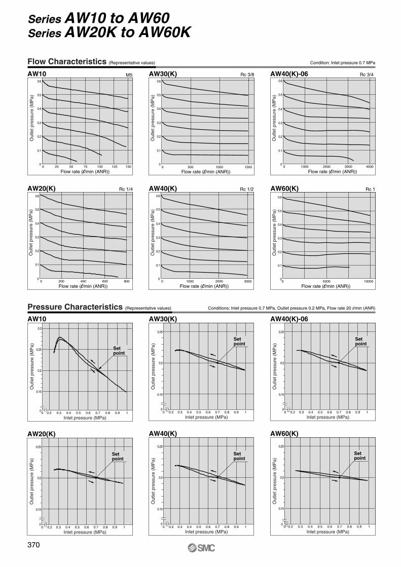
Flow Characteristics (Representative values) Condition: Inlet pressure 0.7 MPa
Pressure Characteristics (Representative values) Conditions: Inlet pressure 0.7 MPa, Outlet pressure 0.2 MPa, Flow rate 20 l/min (ANR)
P0365-P0446-E.qxd 08.11.6 2:09 PM Page 370
A-A o
ot
K
COLHSU
P
SMC
A
A
i
w
q
r
u
t
y
IN OUT
w
y
q
u
r
t
i
IN OUT
w
y
q
u
r
t
i
IN OUT
w
y
q
u
r
e
t
i
IN OUT
371
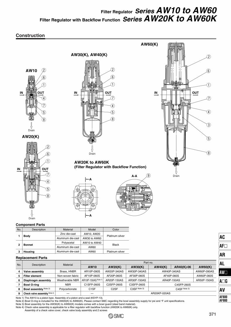
Filter Regulator Series AW10 to AW60Filter Regulator with Backflow Function Series AW20K to AW60K
Construction
AW10
AW20(K)
AW30(K), AW40(K)
AW60(K)
AW20K to AW60K(Filter Regulator with Backflow Function)
Component PartsNo. Description
Body
Bonnet
Housing
Material
Zinc die-cast
Aluminum die-cast
Polyacetal
Aluminum die-cast
Aluminum die-cast
Model
AW10, AW20
AW30 to AW60
AW10 to AW40
AW60
AW60
Platinum silver
Black
Platinum silver
Color
1
2
3
No. Description
Valve assembly
Filter element
Diaphragm assembly
Bowl O-ring
Bowl assembly Note 2)
Check valve assembly Note 4)
Material
Brass, HNBR
Non-woven fabric
Weatherable NBR
NBR
Polycarbonate
—
Part no.
AW10 AW20(K) AW30(K) AW40(K) AW60(K)AR40(K)-06AR10P-090S
AF10P-060S
AR10P-150AS Note 1)
C1SFP-260S
C1SF
—
AW20P-340AS
AF20P-060S
AR20P-150AS
C2SFP-260S
C2SF
AW30P-340AS
AF30P-060S
AR30P-150AS
C3SFP-260S
C3SF Note 3)
AW40P-340AS
AF40P-060S
AR40P-150AS
AW60P-090AS
AW60P-060S
AR50P-150AS
C4SFP-260S
C4SF Note 3)
AR20KP-020AS
4
5
6
7
8
9
Replacement Parts
Note 1) The AW10 is a piston type. Assembly of a piston and a seal (KSYP-13).Note 2) Bowl O-ring is included for the AW20(K) to AW60(K). Please contact SMC regarding the bowl assembly supply for psi and °F unit specifications.Note 3) Bowl assembly for the AW30(K) to AW60(K) models comes with a bowl guard (steel band material).Note 4) Check valve assembly is applicable for a filter regulator with backflow function (AW20K to AW60K) only.
Assembly of a check valve cover, check valve body assembly and 2 screws
Drain
Drain
Drain
Drain
AC
AF�
AR
AL
AW�
A�G
AVAF800AF900
P0365-P0446-E.qxd 08.11.6 2:09 PM Page 371
ww
e
q
r
e
q
r
ot
K
COLHSU
P
SMC
A
A
A-A w
q
w
q
w
372
Series AW10 to AW60Series AW20K to AW60K
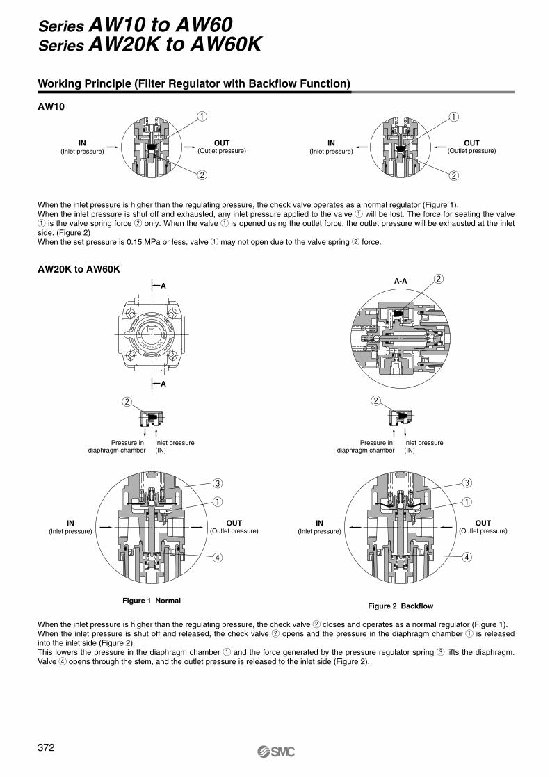
Working Principle (Filter Regulator with Backflow Function)
AW10
IN(Inlet pressure)
OUT(Outlet pressure)
IN(Inlet pressure)
OUT(Outlet pressure)
When the inlet pressure is higher than the regulating pressure, the check valve operates as a normal regulator (Figure 1).When the inlet pressure is shut off and exhausted, any inlet pressure applied to the valve q will be lost. The force for seating the valve q is the valve spring force w only. When the valve q is opened using the outlet force, the outlet pressure will be exhausted at the inlet side. (Figure 2)When the set pressure is 0.15 MPa or less, valve q may not open due to the valve spring w force.
Inlet pressure(IN)
Pressure in diaphragm chamber
Inlet pressure(IN)
Pressure in diaphragm chamber
Figure 2 Backflow
IN(Inlet pressure)
OUT(Outlet pressure)
Figure 1 Normal
IN(Inlet pressure)
OUT(Outlet pressure)
AW20K to AW60K
When the inlet pressure is higher than the regulating pressure, the check valve w closes and operates as a normal regulator (Figure 1).When the inlet pressure is shut off and released, the check valve w opens and the pressure in the diaphragm chamber q is released into the inlet side (Figure 2).This lowers the pressure in the diaphragm chamber q and the force generated by the pressure regulator spring e lifts the diaphragm. Valve r opens through the stem, and the outlet pressure is released to the inlet side (Figure 2).
P0365-P0446-E.qxd 08.11.6 2:09 PM Page 372
AW30(K) to AW40(K)-06
AW60(K)
OS
OUT
O S
K
BC
S
R
DM
V
U
Q
JTN
IN OUT
Y W
Z
F
IN OUT
OUT
OUT
E
K
Q
J
D
U
M
S
BCR
T
N
IN
OUT
E
BC
RS
K
D
V
NT
U
M
Q
J
F
IN
Y W
Z
IN OUT
OUT
373
Filter Regulator Series AW10 to AW60Filter Regulator with Backflow Function Series AW20K to AW60K
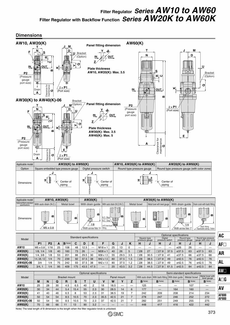
Dimensions
AW10, AW20(K)
GA
Panel fitting dimension
Bracket(Option)
P2(Pressure
gaugeport size)
2 x P1(Port size)
Cle
aran
ce fo
rm
aint
enan
ce
Plate thicknessAW10, AW20(K): Max. 3.5
Drain
A
G
Panel fitting dimension
Plate thicknessAW30(K): Max. 3.5AW40(K): Max. 5
P2(Pressure
gaugeport size)
2 x P1(Port size)
Cle
aran
ce fo
rm
aint
enan
ce
Bracket(Option)
Drain
Bracket(Option)
G
A
P2(Pressure
gaugeport size)
Cle
aran
ce fo
rm
aint
enan
ce
2 x P1(Port size)
Digital pressure switchSquare embedded type pressure gaugeOption Round type pressure gauge
Dimensions
Applicable model AW20(K) to AW60(K) AW10, AW20(K) to AW60(K)Round type pressure gauge (with color zone)
AW20(K) to AW60(K)
J
H Center ofpiping
J
H Center ofpiping
J
H Center ofpiping
With drain guide Drain cock with barb fittingWith drain guideMetal bowl with level gaugeWith auto drain (N.O./N.C.)Metal bowlWith auto drain (N.C.)Optional/Semi-standardspecifications Metal bowl
Dimensions
Applicable model AW10, AW20(K) AW20(K) AW30(K) to AW60(K)
O S
M5 x 0.8
B B
B
1/8Width across flats 14
O
S
BN.O.: BlackN.C.: Gray
ø10 one-touch fitting
B B
B
Width across flats 171/4
B
Barb fittingApplicable tubing: T0604
Note) The total length of B dimension is the length when the filter regulator knob is unlocked.
ModelStandard specifications
Optional specificationsSquare type
pressure gaugeDigital
pressure switchRound type
pressure gauge
P1 P2 A B Note) C D E G JM5 x 0.81/8, 1/41/4, 3/8
1/4, 3/8, 1/23/4
3/4, 1
1/161/81/81/41/41/4
254053707595
108160201239242409
48 73 86 92 93175
12.526 29.537.537.543.5
——
30 38 38 47.5
13 26 29.537.537.543.5
FM18 x 1M28 x 1M38 x 1.5M42 x 1.5M42 x 1.5
—
254055808020
K0 5 3.51.51.23.2
H—
�28�28�28�28�28
J—
27 30.538.538.544.5
H—
�27.8�27.8�27.8�27.8�27.8
J—
37.541 49 49 61.5
Round type pressuregauge (with color zone)
H—
ø37.5ø37.5ø42.5ø42.5ø42.5
J—6366767684
Hø26 ø37.5ø37.5ø42.5ø42.5ø42.5
J266366767684
AW10AW20(K)AW30(K)AW40(K)AW40(K)-06AW60(K)
Model
Optional specifications Semi-standard specifications
Bracket mount Panel mount With auto drain With barb fitting With drain guide Metal bowl Metal bowl withlevel gauge
M253041505070
N283440545466
Q304446545666
R 4.5 5.4 6.5 8.5 8.511
S 6.515.4 8 10.510.513
T405553707090
U2 2.32.32.32.33.2
V18 30 31 35.537 —
W18.528.538.542.542.5—
Y—14192121—
Z—6777—
B Note)
125177242278282448
B Note)
——
209247251417
B Note)
—164208246249416
B Note)
107160214252255422
B Note)
——
234272275442
AW10AW20(K)AW30(K)AW40(K)AW40(K)-06AW60(K)
AC
AF�
AR
AL
AW�
A�G
AVAF800AF900
P0365-P0446-E.qxd 08.11.6 2:09 PM Page 373
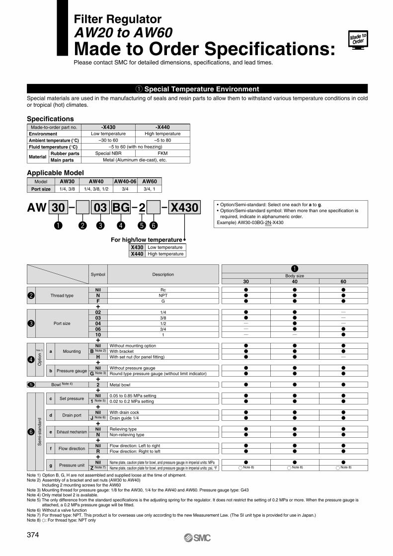
374
q Special Temperature EnvironmentSpecial materials are used in the manufacturing of seals and resin parts to allow them to withstand various temperature conditions in cold or tropical (hot) climates.
Applicable Model
Port size
Model AW30 AW40 AW40-06 AW601/4, 3/8 1/4, 3/8, 1/2 3/4 3/4, 1
30AW 203 BG X430
X430X440
For high/low temperatureLow temperatureHigh temperature
• Option/Semi-standard: Select one each for a to g.• Option/Semi-standard symbol: When more than one specification is
required, indicate in alphanumeric order.Example) AW30-03BG-2N-X430
Specifications
EnvironmentAmbient temperature (°C)Fluid temperature (°C)
Material
Made-to-order part no. -X430High temperature
–5 to 80
FKM
-X440
Rubber partsMain parts
Low temperature–30 to 60
Special NBR–5 to 60 (with no freezing)
Metal (Aluminum die-cast), etc.
Note 1) Option B, G, H are not assembled and supplied loose at the time of shipment.Note 2) Assembly of a bracket and set nuts (AW30 to AW40)
Including 2 mounting screws for the AW60Note 3) Mounting thread for pressure gauge: 1/8 for the AW30, 1/4 for the AW40 and AW60. Pressure gauge type: G43Note 4) Only metal bowl 2 is available.Note 5) The only difference from the standard specifications is the adjusting spring for the regulator. It does not restrict the setting of 0.2 MPa or more. When the pressure gauge is
attached, a 0.2 MPa pressure gauge will be fitted. Note 6) Without a valve functionNote 7) For thread type: NPT. This product is for overseas use only according to the new Measurement Law. (The SI unit type is provided for use in Japan.)Note 8) �: For thread type: NPT only
30 40 60Body sizeDescription
RcNPT
G
Symbol
NilNF
Thread type
1/43/81/23/41
0203040610
Port size
Without mounting optionWith bracketWith set nut (for panel fitting)
NilB Note 2)
HMountinga
Without pressure gaugeRound type pressure gauge (without limit indicator)
NilG Note 3)Pressure gaugeb
0.05 to 0.85 MPa setting0.02 to 0.2 MPa setting
Nil1 Note 5)Set pressurec
With drain cockDrain guide 1/4
NilJ Note 6)Drain portd
Relieving typeNon-relieving type
NilN
Exhaust mechanisme
Flow direction: Left to rightFlow direction: Right to left
NilR
Flow directionf
NilZ Note 7)Pressure unitg
+
Metal bowl2Bowl Note 4)
+
+
+
+
+
+
+
+Name plate, caution plate for bowl, and pressure gauge in imperial units: MPaName plate, caution plate for bowl, and pressure gauge in imperial units: psi, °F
Filter RegulatorAW20 to AW60Made to Order Specifications:Please contact SMC for detailed dimensions, specifications, and lead times.
Sem
i-sta
ndar
dO
ptio
n
Note 1)
Note 8) Note 8) Note 8)
P0365-P0446-E.qxd 08.11.6 2:09 PM Page 374
375
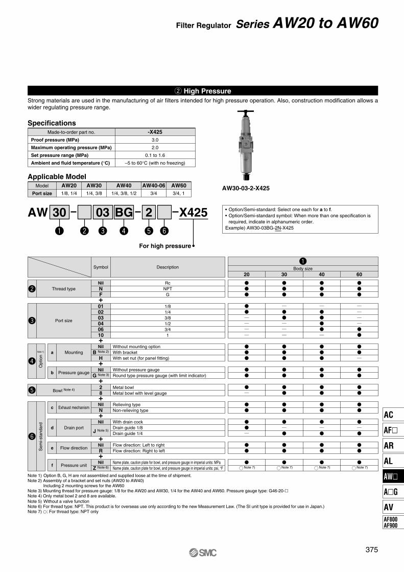
Filter Regulator Series AW20 to AW60
AW30-03-2-X425
w High PressureStrong materials are used in the manufacturing of air filters intended for high pressure operation. Also, construction modification allows a wider regulating pressure range.
Note 1) Option B, G, H are not assembled and supplied loose at the time of shipment.Note 2) Assembly of a bracket and set nuts (AW20 to AW40)
Including 2 mounting screws for the AW60Note 3) Mounting thread for pressure gauge: 1/8 for the AW20 and AW30, 1/4 for the AW40 and AW60. Pressure gauge type: G46-20-�Note 4) Only metal bowl 2 and 8 are available.Note 5) Without a valve functionNote 6) For thread type: NPT. This product is for overseas use only according to the new Measurement Law. (The SI unit type is provided for use in Japan.)Note 7) �: For thread type: NPT only
30AW X425203 BG
For high pressure
Applicable Model
Port size
Model AW20 AW40 AW40-06 AW601/8, 1/4
AW301/4, 3/8 1/4, 3/8, 1/2 3/4 3/4, 1
Specifications
3.0
2.0
0.1 to 1.6
–5 to 60°C (with no freezing)
Made-to-order part no. -X425Proof pressure (MPa)
Maximum operating pressure (MPa)
Set pressure range (MPa)
Ambient and fluid temperature (°C)
20 30 40 60Body sizeDescription
RcNPT
G
Symbol
NilNF
Thread type
1/81/43/81/23/41
010203040610
Port size
Without mounting optionWith bracketWith set nut (for panel fitting)
NilB Note 2)
HMountinga
Without pressure gaugeRound type pressure gauge (with limit indicator)
NilG Note 3)Pressure gaugeb
Relieving typeNon-relieving type
NilNExhaust mechanismc
With drain cockDrain guide 1/8Drain guide 1/4
Nil
J Note 5)Drain portd
Flow direction: Left to rightFlow direction: Right to left
NilR
Flow directione
NilZ Note 6)Pressure unitf
+
+
+
+
+
+
+
+
Metal bowlMetal bowl with level gauge
28Bowl Note 4)
Name plate, caution plate for bowl, and pressure gauge in imperial units: MPaName plate, caution plate for bowl, and pressure gauge in imperial units: psi, °F Note 7) Note 7) Note 7) Note 7)
• Option/Semi-standard: Select one each for a to f.• Option/Semi-standard symbol: When more than one specification is
required, indicate in alphanumeric order.Example) AW30-03BG-2N-X425
Sem
i-sta
ndar
dO
ptio
n
Note 1)
AC
AF�
AR
AL
AW�
A�G
AVAF800AF900
P0365-P0446-E.qxd 08.11.6 2:09 PM Page 375
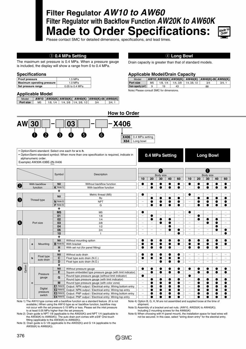
376
SpecificationsProof pressureMaximum operating pressureSet pressure range
1.5 MPa1.0 MPa
0.05 to 0.4 MPa
Applicable Model
Port sizeModel AW10 AW30(K) AW40(K) AW40(K)-06
M5AW20(K)
1/8, 1/4 1/4, 3/8 1/4, 3/8, 1/2 3/4AW60(K)
3/4, 1
Applicable Model/Drain Capacity
Port sizeDrain capacity (cm3)
Model AW10M59
AW30(K)1/4, 3/8
43
AW40(K)1/4, 3/8, 1/2
AW40(K)-063/4
AW20(K)1/8, 1/4
19 88
AW60(K)3/4, 1
30AW X40603
Note 1) The AW10 type comes with a backflow function as a standard feature. (K is not available.) When using the AW10 type as w/ backflow function, backflow may not occur with the set pressure 0.15 MPa or less. Please set the inlet pressure to at least 0.05 MPa higher than the set pressure.
Note 2) Drain guide is NPT 1/8 (applicable to the AW20(K)) and NPT 1/4 (applicable to the AW30(K) to AW60(K)). The auto drain port comes with ø3/8" One-touch fitting (applicable to the AW30(K) to AW60(K)).
Note 3) Drain guide is G 1/8 (applicable to the AW20(K)) and G 1/4 (applicable to the AW30(K) to AW60(K)).
Note 4) Option B, G, H, M are not assembled and supplied loose at the time of shipment.
Note 5) Assembly of a bracket and set nuts. (AW10, AW20(K) to AW40(K)).Including 2 mounting screws for the AW60(K)
Note 6) When choosing with H (panel mount), the installation space for lead wires will not be secured. In this case, select “wiring down entry” for the electrial entry.
e 0.4 MPa Setting r Long BowlThe maximum set pressure is 0.4 MPa. When a pressure gauge is included, the display will show a range from 0 to 0.4 MPa.
Drain capacity is greater than that of standard models.
10 20 30 40 60Body sizeDescription
Without backflow functionWith backflow function
Symbol
NilK Note 1)
With backflowfunction
M51/81/43/81/23/41
M5010203040610
Port size
Without mounting optionWith bracketWith set nut (for panel fitting)
NilB Note 5)
H
NilE
G
ME1 Note 6)
E2 Note 6)
E3 Note 6)
E4 Note 6)
Mountinga
Without pressure gaugeSquare embedded type pressure gauge (with limit indicator)Round type pressure gauge (without limit indicator)Round type pressure gauge (with limit indicator)Round type pressure gauge (with color zone)Output: NPN output / Electrical entry: Wiring bottom entry Output: NPN output / Electrical entry: Wiring top entryOutput: PNP output / Electrical entry: Wiring bottom entry Output: PNP output / Electrical entry: Wiring top entry
Pressuregauge
Digitalpressureswitch
c
+
+
+
10 20 30 40 60
Without auto drainFloat type auto drain (N.C.)Float type auto drain (N.O.)
NilCD
Float typeauto drainb
+
+
Body size
Metric thread (M5)Rc
NPTG
Nil
N Note 2)
F Note 3)
Thread type
Filter Regulator AW10 to AW60Filter Regulator with Backflow Function AW20K to AW60KMade to Order Specifications:Please contact SMC for detailed dimensions, specifications, and lead times.
How to Order
X406X64
0.4 MPa settingLong bowl
0.4 MPa Setting Long Bowl
Note) Please consult SMC for dimensions.
• Option/Semi-standard: Select one each for a to h.• Option/Semi-standard symbol: When more than one specification is required, indicate in
alphanumeric order. Example) AW30K-03BE-2N-X406
Opt
ion
Note 4)
P0365-P0446-E.qxd 08.11.6 2:09 PM Page 376
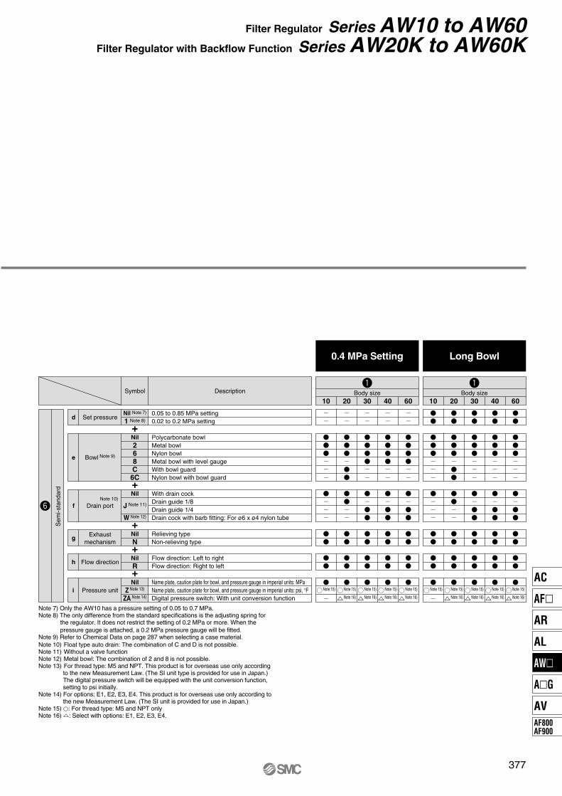
377
Filter Regulator Series AW10 to AW60Filter Regulator with Backflow Function Series AW20K to AW60K
10 20 30 40 60Body sizeDescriptionSymbol
Polycarbonate bowlMetal bowlNylon bowlMetal bowl with level gaugeWith bowl guardNylon bowl with bowl guard
Nil268C
6C
Bowl Note 9)e
Flow direction: Left to rightFlow direction: Right to left
Name plate, caution plate for bowl, and pressure gauge in imperial units: MPaName plate, caution plate for bowl, and pressure gauge in imperial units: psi, °FDigital pressure switch: With unit conversion function
NilR
NilZ Note 13)
ZA Note 14)
Flow directionh
Relieving typeNon-relieving type
NilN
Exhaustmechanism
g
Pressure uniti
+
+
+
+
10 20 30 40 60
With drain cockDrain guide 1/8Drain guide 1/4Drain cock with barb fitting: For ø6 x ø4 nylon tube
Nil
J Note 11)
W Note 12)
Drain portf
Note 15) Note 15)
Note 16)
Note 15)
Note 16)
Note 15)
Note 16)
Note 15)
Note 16)
Note 15) Note 15)
Note 16)
Note 15)
Note 16)
Note 15)
Note 16)
Note 15)
Note 16)
Body size
0.4 MPa Setting Long Bowl
Note 10)
Note 7) Only the AW10 has a pressure setting of 0.05 to 0.7 MPa.Note 8) The only difference from the standard specifications is the adjusting spring for
the regulator. It does not restrict the setting of 0.2 MPa or more. When the pressure gauge is attached, a 0.2 MPa pressure gauge will be fitted.
Note 9) Refer to Chemical Data on page 287 when selecting a case material.Note 10) Float type auto drain: The combination of C and D is not possible.Note 11) Without a valve functionNote 12) Metal bowl: The combination of 2 and 8 is not possible.Note 13) For thread type: M5 and NPT. This product is for overseas use only according
to the new Measurement Law. (The SI unit type is provided for use in Japan.) The digital pressure switch will be equipped with the unit conversion function, setting to psi initially.
Note 14) For options: E1, E2, E3, E4. This product is for overseas use only according to the new Measurement Law. (The SI unit is provided for use in Japan.)
Note 15) �: For thread type: M5 and NPT onlyNote 16) �: Select with options: E1, E2, E3, E4.
0.05 to 0.85 MPa setting0.02 to 0.2 MPa setting
Nil Note 7)
1 Note 8)Set pressured
+
Sem
i-sta
ndar
d
AC
AF�
AR
AL
AW�
A�G
AVAF800AF900
P0365-P0446-E.qxd 08.11.6 2:09 PM Page 377
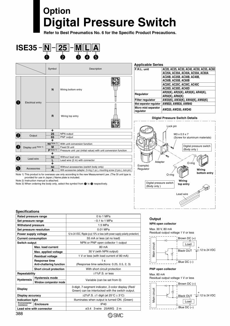
ISE35 N 25 M L A
OptionDigital Pressure SwitchRefer to Best Pneumatics No. 6 for the Specific Product Precautions.
Note 1) This product is for overseas use only according to the new Measurement Law. (The SI unit type is provided for use in Japan.) Name plate is included.
Note 2) Instruction manual is attached. Note 3) When ordering the body only, select the symbol from to respectively.
+
+
+
+
0 to 1 MPa
–0.1 to 1 MPa
1.5 MPa
0.01 MPa
12 to 24 VDC, Ripple (p-p) 10% or less (with power supply polarity protection)
55 mA or less (at no load)
NPN or PNP open collector 1 output
80 mA
30 V (with NPN output)
1 V or less (with load current of 80 mA)
1 s(Response time selections: 0.25, 0.5, 2, 3)
With short circuit protection
±1%F.S. or less
Variable (can be set from 0)
3-digit, 7-segment indicator, 2-color display (Red/Green) can be interlocked with the switch output.
±2%F.S. ±1 digit (at 25°C ± 3°C)
Illuminates when output is turned ON. (Green)
IP40
ø3.4 3-wire 25AWG 2 m
Rated pressure range
Set pressure range
Withstand pressure
Set pressure resolution
Power supply voltage
Current consumption
Switch output
Repeatability
Display
Display accuracy
Indication light
Lead wire with connector
Environmentalresistance
Hysteresis
Max. load current
Max. applied voltage
Residual voltage
Response timeAnti-chattering function
Short circuit protection
Hysteresis mode
Window comparator mode
Enclosure
Specifications
Description
Wiring bottom entry
Wiring top entry
Symbol
N
R
2565
Electrical entry
Output
Lead wire
Accessories
With unit conversion functionFixed SI unitPressure unit: psi (initial value) with unit conversion function
Nil Note 1)
MP Note 1)
Display unit Note 1)
NPN outputPNP output
NilL
Without lead wireLead wire (2 m) with connector
NilA
Without accessories (switch body only)With accessories (adapter, O-ring (1 pc.), mounting screw (2 pcs.), lock pin)
Applicable SeriesAC20, AC25, AC30, AC40, AC50, AC55, AC60AC20A, AC30A, AC40A, AC50A, AC60A
AC20C, AC25C, AC30C, AC40CAC20D, AC30D, AC40DAR20(K), AR25(K), AR30(K), AR40(K), AR50(K), AR60(K)AW20(K), AW30(K), AW40(K), AW60(K)AWM20, AWM30, AWM40
AWD20, AWD30, AWD40
AC20B, AC25B, AC30B, AC40B, AC50B, AC55B, AC60B
F.R.L. unit
Regulator
Filter regulatorMist separator regulatorMicro mist separatorregulator
Diigtal Pressure Switch Details
Lock pin
Adapter
M3 x 0.5 x 7(Screw for aluminum materials)
O-ring
Lead wire
Digital pressure switch(Body only )
Example)Regulator
O-ring
Wiring bottom entry
Wiring top entryDigital pressure switch
(Body only )
NPN open collector
Max. 30 V, 80 mAResidual output voltage 1 V or less
PNP open collector
Max. 80 mAResidual output voltage 1 V or less
+–
+– 12 to 24 VDC
Load
Brown DC (+)
Black OUT
Blue DC (–)
Brown DC (+)
Black OUT
Blue DC (–)
Load
12 to 24 VDC
Mai
n ci
rcui
tM
ain
circ
uit
Output
388
P0365-P0446-E.qxd 08.11.6 2:09 PM Page 388
389
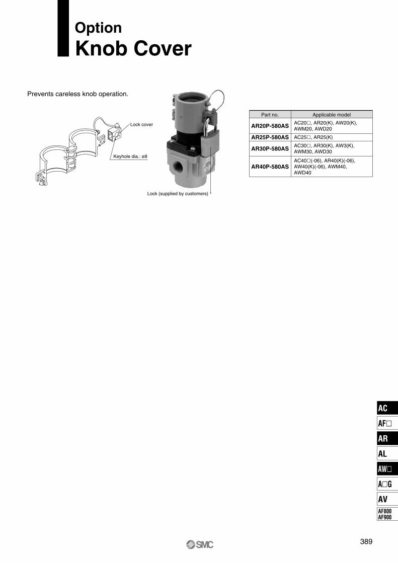
Lock (supplied by customers)
Lock cover
Keyhole dia.: ø8
Prevents careless knob operation.
Applicable model
AR40P-580AS
AR30P-580AS
AR20P-580AS
AR25P-580AS
Part no.
AC20�, AR20(K), AW20(K), AWM20, AWD20
AC30�, AR30(K), AW3(K), AWM30, AWD30
AC40�(-06), AR40(K)(-06), AW40(K)(-06), AWM40, AWD40
AC25�, AR25(K)
Option
Knob Cover
AC
AF�
AR
AL
AW�
A�G
AVAF800AF900
P0365-P0446-E.qxd 08.11.6 2:09 PM Page 389
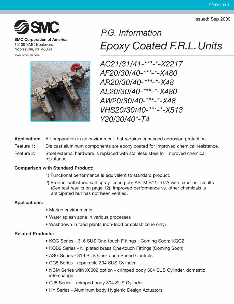
P.G. Information
Epoxy Coated F.R.L.Units
AC21/31/41-***-*-X2217AF20/30/40-***-*-X480AR20/30/40-***-*-X48AL20/30/40-***-*-X480AW20/30/40-***-*-X48VHS20/30/40-***-*-X513Y20/30/40*-T4
Application: Air preparation in an environment that requires enhanced corrosion protection.
Feature 1: Die cast aluminum components are epoxy coated for improved chemical resistance.
Feature 2: Steel external hardware is replaced with stainless steel for improved chemicalresistance.
Comparison with Standard Product:
1) Functional performance is equivalent to standard product.
2) Product withstood salt spray testing per ASTM B117-07A with excellent results(See test results on page 12). Improved performance vs. other chemicals isanticipated but has not been verified.
Applications:
• Marine environments
• Water splash zone in various processes
• Washdown in food plants (non-food or splash zone only)
Related Products:
• KQG Series - 316 SUS One-touch Fittings - Coming Soon: KQG2
• KQB2 Series - Ni plated brass One-touch Fittings (Coming Soon)
• ASG Series - 316 SUS One-touch Speed Controls
• CG5 Series - repairable 304 SUS Cylinder
• NCM Series with X6009 option - crimped body 304 SUS Cylinder, domesticinterchange
• CJ5 Series - crimped body 304 SUS Cylinder
• HY Series - Aluminum body Hygienic Design Actuators
SP093-001I
Issued: Sep 2009
SMC Corporation of America10100 SMC BoulevardNoblesville, IN 46060
www.smcusa.com
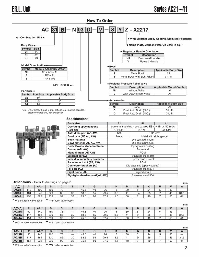
Series AC21~41F.R.L. Unit
2
How To Order
AC 31 B N 03 D V 8 Y Z - X2217— — —
Air Combination Unit
Note: Other sizes, thread forms, options, etc. may be possible,please contact SMC for availability.
With External Epoxy Coating, Stainless Fasteners
Name Plate, Caution Plate On Bowl in psi, ˚F
NPT Threads
Body SizeSymbol
213141
Size1/83/81/2
Model CombinationSymbol
NilAB
Model / Assembly OrderAF + AR + ALAW + ALAF + AR
Port SizeSymbol
020304
Port Size1/43/81/2
Applicable Body Size213141
SpecificationsBody sizeOperating specificationsPort sizeAuto drain port (AF, AW)Bowl type (AF, AL, AW)Body materialBowl material (AF, AL, AW)Body, Bowl surface treatmentBonnet (AR, AW)Manual drain (AF, AW)External screwsIndividual mounting bracketsPanel mount nut (AR, AW)Connector brackets (AC)Fill plug (AL)Sight dome (AL)Sightglasshardware (AF,AL,AW)
21 31 41
AC21AC31AC41
AC A*140181238
AA**190245322
B160220239
C738692
E—3038
F45.558.575.5
G405580
J2629.537.5
K53.51.5
M304150
N516481
Q243540
U577
V334550
W—34.541
Same as standard - see catalog ES40-42D or NC160A1/4” NPTN/AMetal
1/4” NPTMetal with sight gauge
Die cast aluminumDie cast aluminumEpoxy resin coating
PolyacetalPOM
Stainless steel 410Epoxy coated steel
POMDie cast zinc (epoxy coated)
Stainless steel 304Polycarbonate
Stainless steel 304
3/8” NPT 1/2” NPT
BowlSymbol
28
DescriptionMetal Bowl
Metal Bowl With Sight Glass
Applicable Body Size21
31, 41
Residual Pressure Relief ValveSymbol
NilV
DescriptionWithout Valve
With Downstream Valve
Applicable Model ComboAllAll
AccessoriesSymbol
NilCD
DescriptionNone
Float Auto Drain (N.C.)Float Auto Drain (N.O.)
Applicable Body SizeAll
31, 4131, 41
Regulator Handle OrientationSymbol
NilY
DescriptionDownward HandleUpward Handle
Dimensions - Refer to drawings on page 3 mm
AC21AAC31AAC41A
A*90117154
AA**140181238
B160220239
C738692
E—3038
F45.558.575.5
G405580
J2629.537.5
K53.51.5
M304150
N516481
Q243540
U577
V334550
W—34.541
mm
AC21BAC31BAC41B
A*90117154
AA**140181238
B160220239
C738692
E—3038
F45.558.575.5
G405580
J2629.537.5
K53.51.5
M304150
N516481
Q243540
U577
V334550
W—34.541
mm
AC-A
AC-B
* Without relief valve option ** With relief valve option
* Without relief valve option ** With relief valve option
* Without relief valve option ** With relief valve option
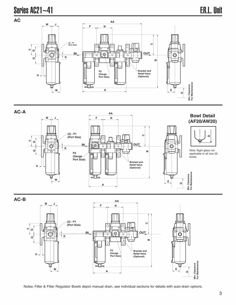
3
Series AC21~41 F.R.L. UnitAC AA
NF
C
B
E
G
K
W
U
QQV
M J
(2) - P1(Port Size)
P2(GaugePort Size)
Min
.Cle
aran
ceF
or
Mai
nte
nan
ce
IN OUT
Bracket andRelief Valve(Optional)
A
AC-A AA
NF
C
B
EG
K
W
U
QQV
M J
(2) - P1(Port Size)
P2(GaugePort Size)
Min
.Cle
aran
ceF
or
Mai
nte
nan
ce
IN OUT
A
Bracket andRelief Valve(Optional)
AC-B AA
NF
CB
E
G
K
W
U
QQV
M J
(2) - P1(Port Size)
P2(GaugePort Size)
Min
.Cle
aran
ceF
or
Mai
nte
nan
ce
IN OUT
Bracket andRelief Valve(Optional)
A
Note: Sight glass notapplicable to all size 20bowls.
Notes: Filter & Filter Regulator Bowls depict manual drain, see individual sections for details with auto-drain options.
D
Bowl Detail(AF20/AW20)
4
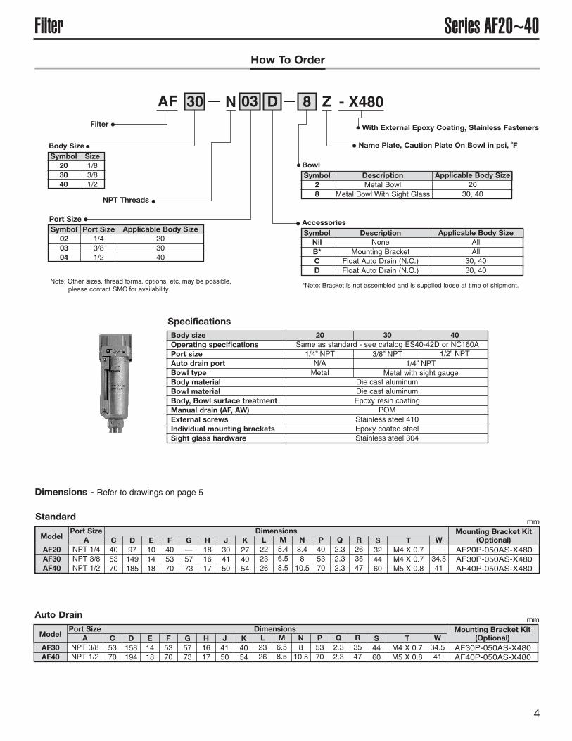
Series AF20~40FilterHow To Order
AF 30 N 03 D 8 Z - X480— —
Filter
Note: Other sizes, thread forms, options, etc. may be possible,please contact SMC for availability. *Note: Bracket is not assembled and is supplied loose at time of shipment.
With External Epoxy Coating, Stainless Fasteners
Name Plate, Caution Plate On Bowl in psi, ˚F
NPT Threads
Body SizeSymbol
203040
Size1/83/81/2
Port SizeSymbol
020304
Port Size1/43/81/2
Applicable Body Size203040
SpecificationsBody sizeOperating specificationsPort sizeAuto drain portBowl typeBody materialBowl materialBody, Bowl surface treatmentManual drain (AF, AW)External screwsIndividual mounting bracketsSight glass hardware
20 30 40
AF20AF30AF40
ANPT 1/4NPT 3/8NPT 1/2
C405370
Same as standard - see catalog ES40-42D or NC160A1/4” NPTN/AMetal
1/4” NPTMetal with sight gauge
Die cast aluminumDie cast aluminumEpoxy resin coating
POMStainless steel 410Epoxy coated steelStainless steel 304
3/8” NPT 1/2” NPT
BowlSymbol
28
DescriptionMetal Bowl
Metal Bowl With Sight Glass
Applicable Body Size20
30, 40
AccessoriesSymbol
NilB*CD
DescriptionNone
Mounting BracketFloat Auto Drain (N.C.)Float Auto Drain (N.O.)
Applicable Body SizeAllAll
30, 4030, 40
Dimensions Mounting Bracket Kit(Optional)
AF20P-050AS-X480AF30P-050AS-X480AF40P-050AS-X480
ModelPort Size
D97149185
E101418
F405370
G—5773
H181617
J304150
K274054
L222326
M5.46.58.5
N8.4810.5
P405370
Q2.32.32.3
R263547
S324460
W—34.541
TM4 X 0.7M4 X 0.7M5 X 0.8
AF30AF40
ANPT 3/8NPT 1/2
C5370
Dimensions Mounting Bracket Kit(Optional)
AF30P-050AS-X480AF40P-050AS-X480
ModelPort Size
D158194
E1418
F5370
G5773
H1617
J4150
K4054
L2326
M6.58.5
N810.5
P5370
Q2.32.3
R3547
S4460
W34.541
TM4 X 0.7M5 X 0.8
Auto Drain
Standard
Dimensions - Refer to drawings on page 5
mm
mm
5
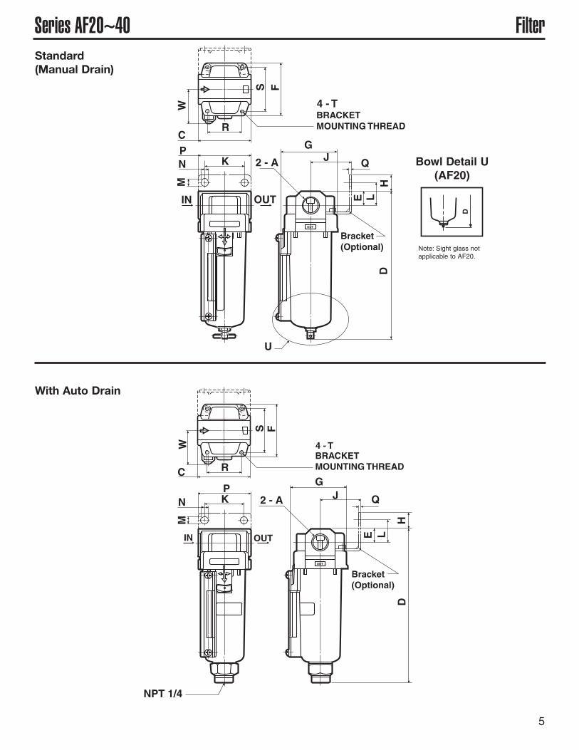
Series AF20~40 FilterStandard(Manual Drain)
RC
4 - TBRACKETMOUNTING THREAD
S F
WM
IN OUT
PKN 2 - A
U
D
GJ Q
HLE
Bracket(Optional)
With Auto Drain
RC
4 - TBRACKETMOUNTING THREAD
S F
WM
IN OUT
PKN 2 - A
D
GJ Q
H
LE
NPT 1/4
Bracket(Optional)
D
Note: Sight glass notapplicable to AF20.
Bowl Detail U(AF20)
6
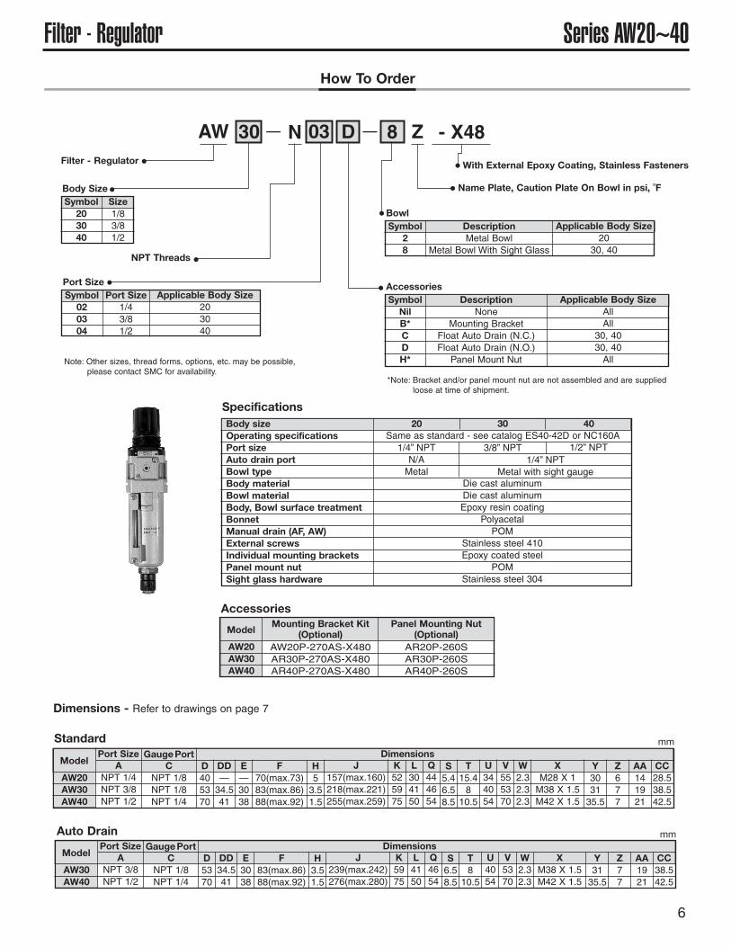
Series AW20~40Filter - RegulatorHow To Order
AW 30 N 03 D 8 Z - X48— —
Filter - Regulator
Note: Other sizes, thread forms, options, etc. may be possible,please contact SMC for availability.
With External Epoxy Coating, Stainless Fasteners
Name Plate, Caution Plate On Bowl in psi, ˚F
NPT Threads
Body SizeSymbol
203040
Size1/83/81/2
Port SizeSymbol
020304
Port Size1/43/81/2
Applicable Body Size203040
SpecificationsBody sizeOperating specificationsPort sizeAuto drain portBowl typeBody materialBowl materialBody, Bowl surface treatmentBonnetManual drain (AF, AW)External screwsIndividual mounting bracketsPanel mount nutSight glass hardware
20 30 40Same as standard - see catalog ES40-42D or NC160A1/4” NPTN/AMetal
1/4” NPTMetal with sight gauge
Die cast aluminumDie cast aluminumEpoxy resin coating
PolyacetalPOM
Stainless steel 410Epoxy coated steel
POMStainless steel 304
3/8” NPT 1/2” NPT
BowlSymbol
28
DescriptionMetal Bowl
Metal Bowl With Sight Glass
Applicable Body Size20
30, 40
AccessoriesSymbol
NilB*CDH*
DescriptionNone
Mounting BracketFloat Auto Drain (N.C.)Float Auto Drain (N.O.)Panel Mount Nut
Applicable Body SizeAllAll
30, 4030, 40All
AW30AW40
ANPT 3/8NPT 1/2
DimensionsModel
Port SizeC
NPT 1/8NPT 1/4
GaugePortD5370
DD34.541
E3038
F83(max.86)88(max.92)
H3.51.5
J239(max.242)276(max.280)
K5975
L4150
Q4654
S6.58.5
U4054
T810.5
V5370
W2.32.3
XM38 X 1.5M42 X 1.5
Y3135.5
Z77
AA1921
CC38.542.5
AW20AW30AW40
ANPT 1/4NPT 3/8NPT 1/2
DimensionsModel
Port SizeC
NPT 1/8NPT 1/8NPT 1/4
GaugePortD405370
DD—34.541
E—3038
F70(max.73)83(max.86)88(max.92)
H53.51.5
J157(max.160)218(max.221)255(max.259)
K525975
L304150
Q444654
S5.46.58.5
U344054
T15.4810.5
AW20AW30AW40
Mounting Bracket Kit(Optional)
AW20P-270AS-X480AR30P-270AS-X480AR40P-270AS-X480
Model
V555370
W2.32.32.3
XM28 X 1M38 X 1.5M42 X 1.5
Y303135.5
Z677
AA141921
CC28.538.542.5
Panel Mounting Nut(Optional)
AR20P-260SAR30P-260SAR40P-260S
Auto Drain
Standard
Accessories
Dimensions - Refer to drawings on page 7
mm
mm
*Note: Bracket and/or panel mount nut are not assembled and are suppliedloose at time of shipment.
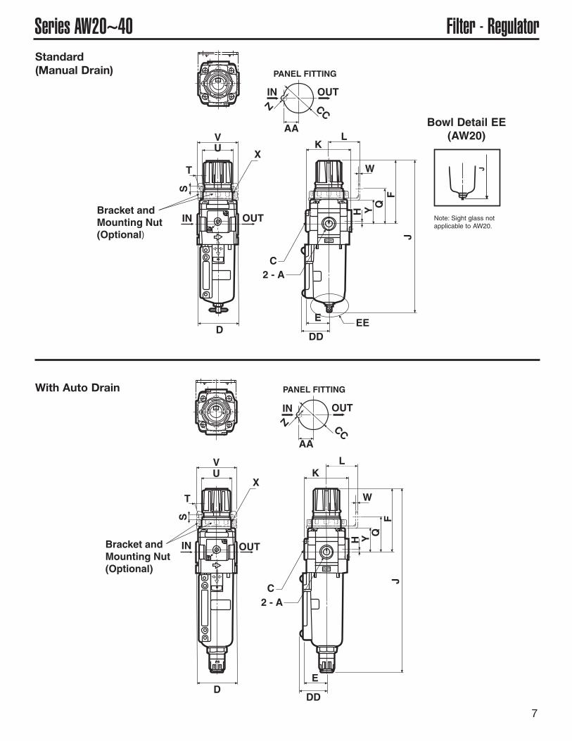
7
Series AW20~40 Filter - RegulatorStandard(Manual Drain)
C
IN OUT
2 - A
H
IN OUT
AA
Z CC
PANEL FITTING
DD
E EE
J
Y QF
W
KL
X
VU
TS
D
Bracket andMounting Nut(Optional)
With Auto Drain
C
IN OUT
2 - A
H
IN OUT
AA
Z CC
PANEL FITTING
DD
E
J
Y QF
W
KL
X
VU
T
S
D
Bracket andMounting Nut(Optional)
J
Bowl Detail EE(AW20)
Note: Sight glass notapplicable to AW20.
8
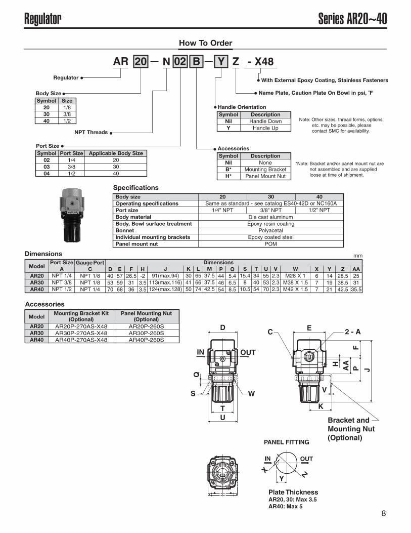
Series AR20~40RegulatorHow To Order
AR 20 N 02 B Y Z - X48— —
Regulator
Note: Other sizes, thread forms, options,etc. may be possible, pleasecontact SMC for availability.
With External Epoxy Coating, Stainless Fasteners
Name Plate, Caution Plate On Bowl in psi, ˚F
NPT Threads
Body SizeSymbol
203040
Size1/83/81/2
Port SizeSymbol
020304
Port Size1/43/81/2
Applicable Body Size203040
SpecificationsBody sizeOperating specificationsPort sizeBody materialBody, Bowl surface treatmentBonnetIndividual mounting bracketsPanel mount nut
20 30 40Same as standard - see catalog ES40-42D or NC160A1/4” NPT
Die cast aluminumEpoxy resin coating
PolyacetalEpoxy coated steel
POM
3/8” NPT 1/2” NPT
Handle OrientationSymbol
NilY
DescriptionHandle DownHandle Up
AccessoriesSymbol
NilB*H*
DescriptionNone
Mounting BracketPanel Mount Nut
AR20AR30AR40
ANPT 1/4NPT 3/8NPT 1/2
DimensionsModel
Port SizeC
NPT 1/8NPT 1/8NPT 1/4
GaugePortD405370
E575968
F26.53136
H-23.53.5
J91(max.94)113(max.116)124(max.128)
K304150
L656674
M37.537.542.5
P444654
S15.4810.5
Q5.46.58.5
AR20AR30AR40
Mounting Bracket Kit(Optional)
AR20P-270AS-X48AR30P-270AS-X48AR40P-270AS-X48
Model
T344054
U555370
WM28 X 1M38 X 1.5M42 X 1.5
X677
Y141921
Z28.538.542.5
AA253135.5
Panel Mounting Nut(Optional)
AR20P-260SAR30P-260SAR40P-260S
V2.32.32.3
C
IN OUT
2 - AH
IN OUT
AA
X Z
PANEL FITTING
E
J
Y
Q
F
W
K
V
UT
S
D
P
Plate ThicknessAR20, 30: Max 3.5AR40: Max 5
Bracket andMounting Nut(Optional)
Dimensions
Accessories
mm
*Note: Bracket and/or panel mount nut arenot assembled and are suppliedloose at time of shipment.
9
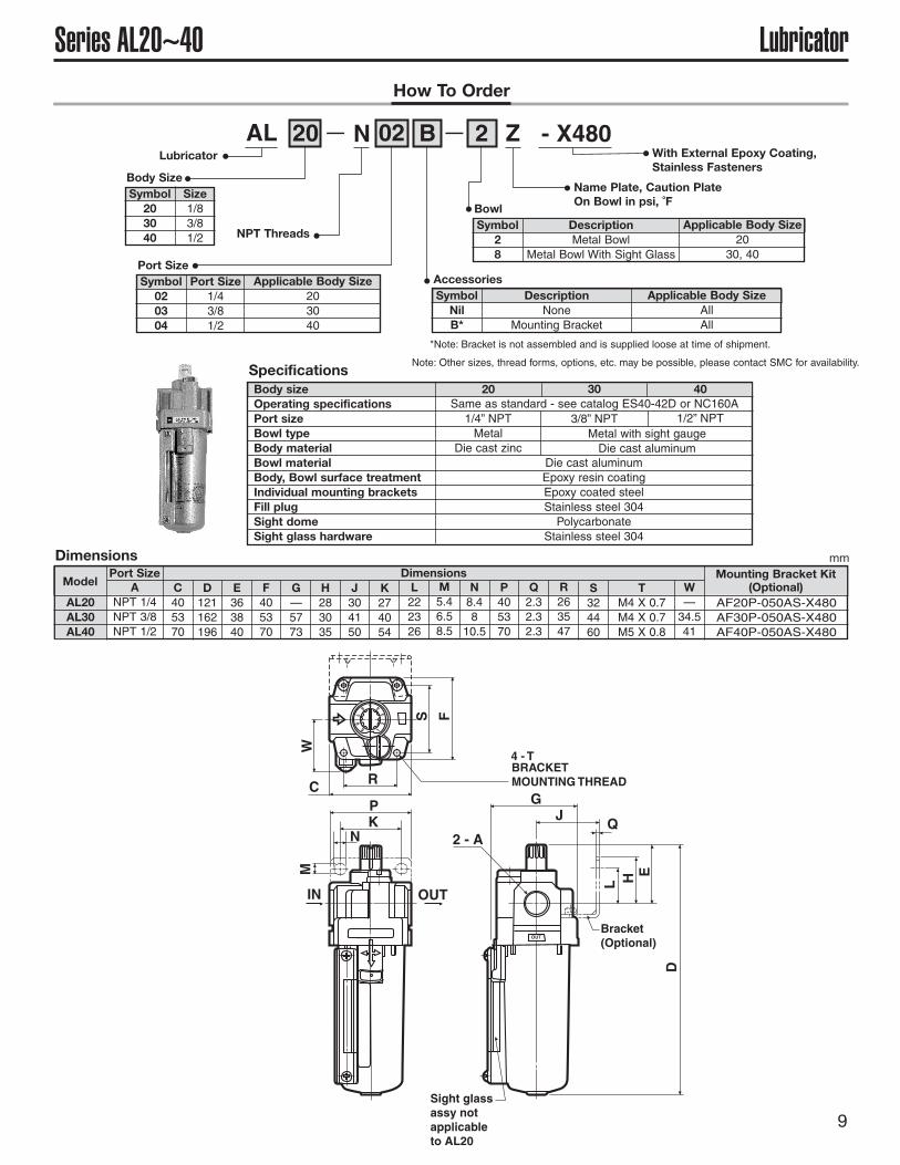
Series AL20~40 LubricatorHow To Order
AL 20 N 02 B 2 Z - X480— —Lubricator
Note: Other sizes, thread forms, options, etc. may be possible, please contact SMC for availability.
With External Epoxy Coating,Stainless Fasteners
Name Plate, Caution PlateOn Bowl in psi, ˚F
NPT Threads
Body SizeSymbol
203040
Size1/83/81/2
Port SizeSymbol
020304
Port Size1/43/81/2
Applicable Body Size203040
BowlSymbol
28
DescriptionMetal Bowl
Metal Bowl With Sight Glass
Applicable Body Size20
30, 40
AccessoriesSymbol
NilB*
DescriptionNone
Mounting Bracket
Applicable Body SizeAllAll
Specifications
Dimensions
Body sizeOperating specificationsPort sizeBowl typeBody materialBowl materialBody, Bowl surface treatmentIndividual mounting bracketsFill plugSight domeSight glass hardware
20 30 40Same as standard - see catalog ES40-42D or NC160A1/4” NPTMetal
Die cast zincMetal with sight gaugeDie cast aluminum
Die cast aluminumEpoxy resin coatingEpoxy coated steelStainless steel 304Polycarbonate
Stainless steel 304
3/8” NPT 1/2” NPT
AL20AL30AL40
ANPT 1/4NPT 3/8NPT 1/2
C405370
Dimensions Mounting Bracket Kit(Optional)
AF20P-050AS-X480AF30P-050AS-X480AF40P-050AS-X480
ModelPort Size
D121162196
E363840
F405370
G—5773
H283035
J304150
K274054
L222326
M5.46.58.5
N8.4810.5
P405370
Q2.32.32.3
R263547
S324460
W—34.541
TM4 X 0.7M4 X 0.7M5 X 0.8
RC
4 - TBRACKETMOUNTING THREAD
S F
WM
IN OUT
PK
N 2 - A
D
GJ
Q
HL
E
1
23
456
78
9
Bracket(Optional)
Sight glassassy notapplicableto AL20
mm
*Note: Bracket is not assembled and is supplied loose at time of shipment.
10
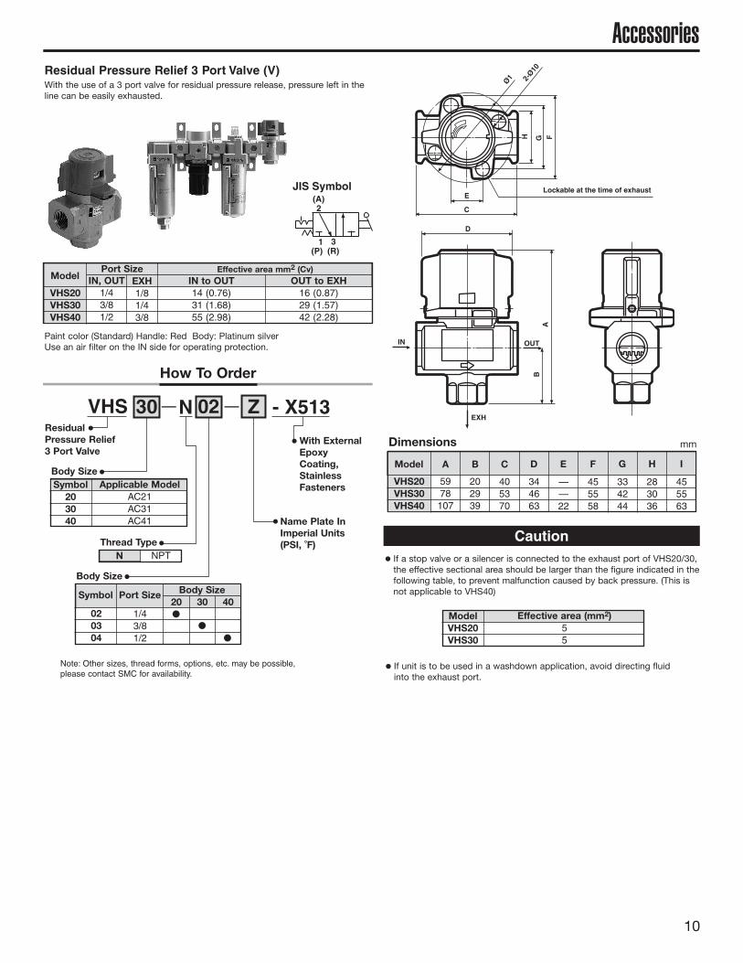
Accessories
Note: Other sizes, thread forms, options, etc. may be possible,please contact SMC for availability.
C
Ø1
Lockable at the time of exhaust
F
IN OUT
B
D
GH
A
E
EXH
2-Ø10
VHS20VHS30VHS40
IN, OUT1/43/81/2
IN to OUT14 (0.76)31 (1.68)55 (2.98)
OUT to EXH16 (0.87)29 (1.57)42 (2.28)
Effective area mm2 (Cv)Model
Port SizeEXH1/81/43/8
VHS20VHS30VHS40
5978107
Model A
Paint color (Standard) Handle: Red Body: Platinum silverUse an air filter on the IN side for operating protection.
If a stop valve or a silencer is connected to the exhaust port of VHS20/30,the effective sectional area should be larger than the figure indicated in thefollowing table, to prevent malfunction caused by back pressure. (This isnot applicable to VHS40)
If unit is to be used in a washdown application, avoid directing fluidinto the exhaust port.
With the use of a 3 port valve for residual pressure release, pressure left in theline can be easily exhausted.
Residual Pressure Relief 3 Port Valve (V)
JIS Symbol(A)
(P) (R)
2
1 3
202939
405370
344663
——22
455558
334244
283036
455563
B C D E F G H I
Caution
ModelVHS20VHS30
Effective area (mm2)55
How To Order
VHS 30 N 02 Z - X513— —
With ExternalEpoxyCoating,StainlessFasteners
Name Plate InImperial Units(PSI, ˚F)
ResidualPressure Relief3 Port Valve
Body SizeSymbol
203040
Applicable ModelAC21AC31AC41
Body Size
Symbol Port Size Body Size20 30 40
020304
1/43/81/2
Thread TypeN NPT
Dimensions mm
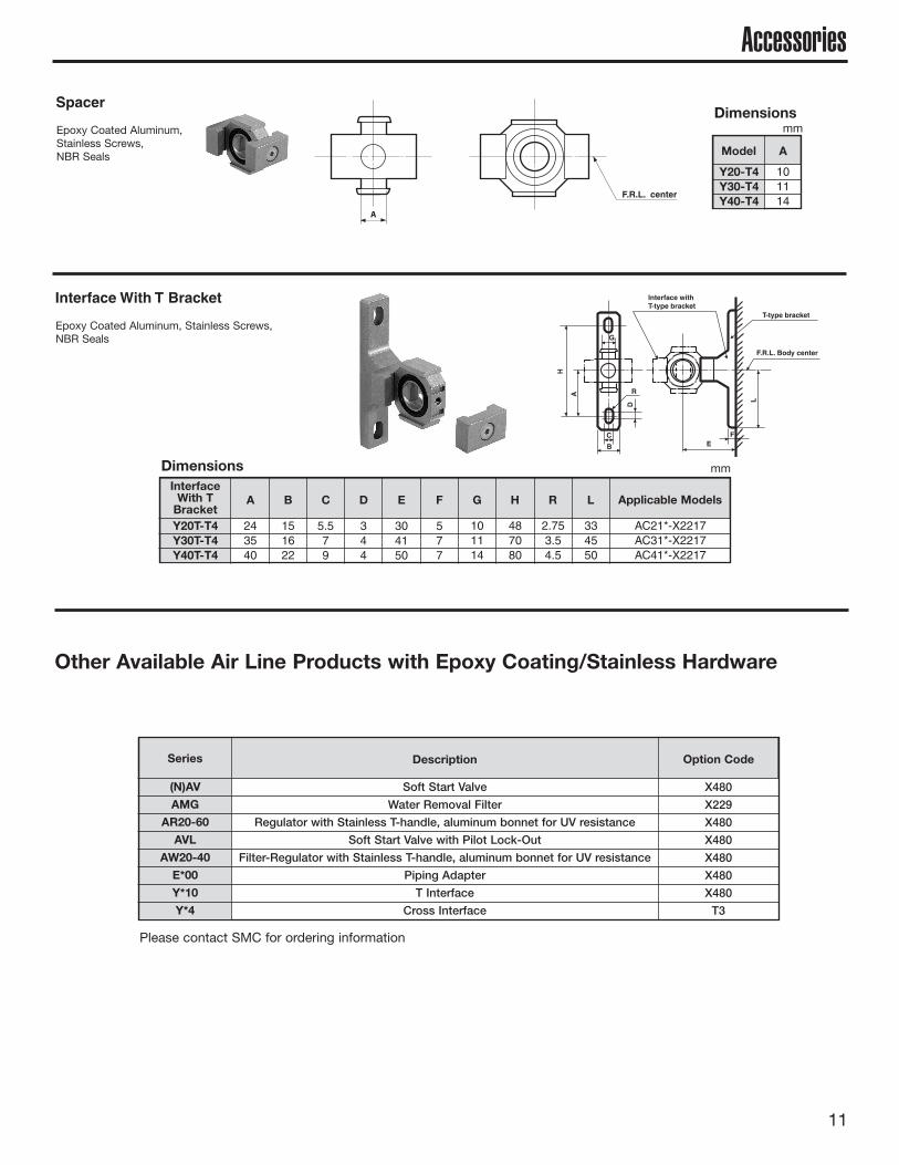
Y20T-T4Y30T-T4Y40T-T4
A B C D E F G H R L Applicable ModelsInterface
With TBracket
243540
151622
5.579
344
304150
577
101114
487080
2.753.54.5
334550
AC21*-X2217AC31*-X2217AC41*-X2217
Interface withT-type bracket
F
B
D
G
H
L
E
T-type bracket
F.R.L. Body center
RA
C
Epoxy Coated Aluminum, Stainless Screws,NBR Seals
Interface With T Bracket
Epoxy Coated Aluminum,Stainless Screws,NBR Seals
Spacer
Dimensions
(N)AV
AMG
AR20-60
AVL
AW20-40
E*00
Y*10
Y*4
Soft Start Valve
Water Removal Filter
Regulator with Stainless T-handle, aluminum bonnet for UV resistance
Soft Start Valve with Pilot Lock-Out
Filter-Regulator with Stainless T-handle, aluminum bonnet for UV resistance
Piping Adapter
T Interface
Cross Interface
X480
X229
X480
X480
X480
X480
X480
T3
Description Option CodeSeries
Other Available Air Line Products with Epoxy Coating/Stainless Hardware
mm
11
Accessories
F.R.L. center
Y20-T4Y30-T4Y40-T4
101114
Model A
Dimensionsmm
Please contact SMC for ordering information
12
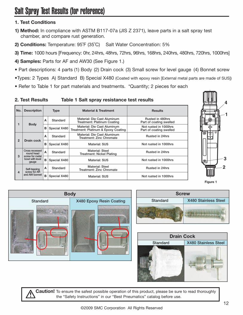
Salt Spray Test Results (for reference)1. Test Conditions
1) Method: In compliance with ASTM B117-07a (JIS Z 2371), leave parts in a salt spray testchamber, and compare rust generation.
2) Conditions: Temperature: 95˚F (35˚C) Salt Water Concentration: 5%
3) Time: 1000 hours [Frequency: 0hr, 24hrs, 48hrs, 72hrs, 96hrs, 168hrs, 240hrs, 480hrs, 720hrs, 1000hrs]
4) Samples: Parts for AF and AW30 (See Figure 1.)
• Part descriptions: 4 parts (1) Body (2) Drain cock (3) Small screw for level gauge (4) Bonnet screw
•Types: 2 Types A) Standard B) Special X480 (Coated with epoxy resin [External metal parts are made of SUS])
• Refer to Table 1 for part materials and treatments. *Quantity; 2 pieces for each
2. Test Results Table 1 Salt spray resistance test results
Body Screw
Drain Cock
Standard X480 Epoxy Resin Coating Standard X480 Stainless Steel
Standard X480 Stainless Steel
Figure 1
1A
B
A
B
A
B
A
B
Standard
Special X480
Standard
Special X480
Standard
Special X480
Standard
Special X480
Material: Die Cast AluminumTreatment: Platinum CoatingMaterial: Die Cast Aluminum
Treatment: Platinum & Epoxy Coating
Material: Die Cast AluminumTreatment: Zinc Chromate
Rusted in 480hrsPart of coating swelledNot rusted in 1000hrsPart of coating swelled
Rusted in 24hrs
Not rusted in 1000hrs
Not rusted in 1000hrs
Not rusted in 1000hrs
Rusted in 24hrs
Rusted in 24hrsMaterial: SteelTreatment: Zinc Chromate
Material: SteelTreatment: Nickel Plating
Material: SUS
Material: SUS
Material: SUS
Body
Drain cock2
3
Cross recessedround head
screw formetalbowl with level
gauge
Self-tappingscrew for ARand AWbonnet
4
No. Description Type Material & Treatment Results
2
3
1
4
Caution! To ensure the safest possible operation of this product, please be sure to read thoroughlythe “Safety Instructions” in our “Best Pneumatics” catalog before use.
©2009 SMC Corporation All Rights Reserved