Embed Size (px)
Citation preview
Operation Manual
Modular UPS
MD Series
380V400V415V
Safety Precautions This manual is about the installation and operation of MD Series modular UPS (Hereinafter referred
to as UPS)
Please carefully read this manual prior to installation
The UPS must be debugged and maintained by the engineer commissioned by the manufacturer or
the agent Otherwise human safety may be endangered and the damage of UPS shall not belong to the
warranty scope
APPLICABLE STANDARDS
This product complies with CE 7323 amp 9368 (low voltage safety) and 89336 (EMC) and EMC
standards of Australia and New Zealand (C-Tick) and the following UPS product standards
IEC62040-1-1-General and safety requirements for use in operator access area
IECEN62040-2 EMC requirements CLASS C3
IEC62040-3 Performance requirements and test methods
WARNING- High earth leakage current
Earth connection is critical before connecting the input supply (include both utility supply and battery)
This equipment must be earthed in accordance with local electrical authority codes of practice
Earth leakage current exceeds 35 mA and is less than 1000 mA
Transient and steady-state earth leakage currents which may occur when starting the equipment
should be taken into account when selecting instantaneous RCCB or RCD devices
Residual Current Circuit Breakers ( RCCBs) must be selected insensitive to DC unidirectional pulses
( class A ) and transient current pulses ( RCCBs)
Note it that the earth leakage currents of the load will also flow across RCCB or RCD
Components that can be maintained by user
All the equipment maintenance and servicing procedures involving internal access need special tools
and should be carried out only by trained personnel The components that can only be accessed by
opening the protective cover with tools cannot be maintained by user
This UPS full complies with ldquoIEC62040-1-1-General and safety requirements for use in operator
access area UPS dangerous voltages are present within the battery box However the risk of
contact with these high voltages is minimized for non-service personnel Since the component with
dangerous voltage can only be touched by opening the protective cover with a tool the possibility of
touching high voltage component is minimized No risk exists to any personnel when operating the
equipment in the normal manner following the recommended operating procedures in this manual
Battery Voltage Higher Than 400Vdc
All the battery maintenance and servicing procedures involving internal access need special tools or
keys and should be carried out only by trained personnel
SPECIAL CARE SHOULD BE TAKEN WHEN WORKING WITH THE BATTERIES ASSOCIATED
WITH THIS EQUIPMENT WHEN CONNECTED TOGETHER THE BATTERY TERMINAL
VOLTAGE WILL EXCEED 400Vdc AND IS POTENTIALLY LETHAL
Battery manufacturers supply details of the necessary precautions to be observed when working on
or in the vicinity of a large bank of battery cells These precautions should be followed implicitly at all
times Particular attention should be paid to the recommendations concerning local environmental
conditions and the provision of protective clothing first aid and fire-fighting facilities
Contents
Chapter 1 Installation 4
11 Introduction 4
12 Initial Checking 4
13 Positioning 5
131 Distribution Room 5
132 Battery Room 5
133 Storing 5
14 Disassembly Initial Checking and Positioning 5
141 System Packaging 5
142 Module Packaging 7
143 UPS Composition 9
144 Operation Space 10
145 Front and Back Access 10
146 Final Positioning 10
147 Power Module Installation 10
148 Cable Entry 11
15 Protective Devices 12
151 Rectifier and Bypass Input Supply of the UPS 12
152 Battery 12
153 UPS Output 13
16 Power Cables 13
161 Maximum stable state current and configuration of cable system please refer to table 1-2 13
162 Cable Connection 14
17 Control and Communication Cabling 14
171 Dry Contact Interface of Battery and Environmental Temperature Detection 15
172 Remote EPO Input Port 15
173 Generator Input Dry Contact 16
174 BCB Input Port 17
175 Battery Warning Output Dry Contact Interface 17
176 Integrated Warning Output Dry Contact Interface 18
177 Mains Failure Warning Output Dry Contact Interface 18
178 RS232 Port and SNMP Card Port 19
179 LBS (Load Bus Synchronizer) Port 19
18 Installation Drawing 19
Chapter 2 Operations 24
21 Introduction 24
211 Principle 24
212 Bypass Module 25
22 Operation Mode 25
221 Normal Mode 26
222 Battery Mode 26
223 Auto-Restart Mode 26
224 Bypass Mode 26
225 Maintenance Mode 26
226 ECO Mode 27
227 Frequency Converters Mode 27
23 Battery Management 27
231 Normal Function 27
232 Advanced Functions (Battery Self-checking and Maintenance) 27
24 Battery Protection 28
Chapter 3 Operating Steps 29
31 Power Switches 29
32 UPS Start-up 29
321 Normal Module Start 30
33 Procedure for Switching between Operation Modes 33
331 Procedure for Switching the UPS into Battery mode from Normal Mode 33
332 Procedure for Switching the UPS into Bypass mode from Normal Mode 33
333 Procedure for Switching the UPS into Normal from Bypass Mode 33
334 Procedure for Switching the UPS into a Maintenance Bypass from Normal Mode 33
335 Procedure for Switching the UPS into Normal from a Maintenance Bypass Mode 33
34 Procedure for Completely Powering down a UPS 34
35 EPO Procedure 34
36 Language Selection 34
37 Control Password 34
Chapter 4 Operator Control and Display Panel 35
41 Introduction 35
411 LED Indicator 36
412 Audible Alarm (buzzer) 36
413 Functional Keys 37
42 LCD Display Type 37
43 Detailed Description of Menu Items 40
44 Alarm List 42
Chapter 5 Installation of Parallel Operation System 45
Chapter 6 Maintenance 47
61 Instruction to Power Bypass and Output Power Distribution Module 47
611 Precautions 47
612 Instruction to Power Module 47
613 Instruction to Bypass Module 47
62 Replacing Dust Screen (optional) 48
Chapter 7 Product Specification 49
71 Applicable Standards 49
72 Environmental Characteristics 49
73 Mechanical Characteristics 49
74 Electrical Characteristics (Input Rectifier) 50
75 Electrical Characteristics (Intermediate DC Link) 50
76 Electrical Characteristics (Inverter Output) 51
77 Electrical Characteristics(Bypass Mains Input) 52
78 Efficiency 52
Appendix A A Guidebook to Ordering and Selection of MU System 53
Chapter 1 Installation
4
Chapter 1 Installation
This chapter introduces the installation of MD series UPS (hereby referred to as UPS) including
initial checking sitting positioning cabling and installation drawings
11 Introduction
This chapter introduces the relevant requirements for positioning and cabling of the UPS
As each site has its requirements this chapter provides step-by-step installation instructions which
acts as a guide to the general procedures and practices that should be observed by the installing
engineer
Warning-Installation can only be done by authorized engineers
1 Do not apply electrical power to the UPS equipment before the approval of commissioning
engineer
2 The UPS should be installed by a qualified engineer in accordance with the information contained
in this chapter
Note 3-Phase 4-Wire Input Power is required
The standard UPS can be connected to TN TT and IT AC distribution system (IEC60364-3) of
3-phase 5-wire
WARNING battery hazards
SPECIAL CARE SHOULD BE TAKEN WHEN WORKING WITH THE BATTERIES ASSOCIATED
WITH THIS EQUIPMENT When connecting the battery the battery terminal voltage will exceed
400Vdc and is potentially lethal
Eye protection should be worn to prevent injury from accidental electrical arcs
Remove rings watches and all metal objects
Only use tools with insulated handles
Wear rubber gloves
If a battery leaks electrolyte or is otherwise physically damaged it must be replaced stored in a
container resistant to sulfuric acid and disposed of in accordance with local regulations
If electrolyte comes into contact with the skin the affected area should be washed immediately
with water
12 Initial Checking
Perform the following checking operations prior to the UPS installation
1 Visually examine if there is any damage inside and outside the UPS rack and battery equipment
due to the transportation Report any such damage to the shipper immediately
2 Verify the product label and confirm the correctness of the equipment The equipment label is
attached on the back of front door The UPS model capacity and main parameters are marked on
the label
Chapter 1 Installation
5
13 Positioning
131 Distribution Room
The UPS is designed for indoor installation which shall be located in a clean environment with
adequate ventilation to keep the environmental temperature within the required specification The UPS
uses forced convection cooling by internal fans Cooling air enters the module through ventilation grills
located at the front part of the cabinet and exhausted through grills located in the rear part of the cabinet
Please do not block the ventilation holes
If necessary a system of extractor fans should be installed to aid cooling-air flow An air filter should
be used when the UPS is to operate in a dirty environment and should be regularly cleaned to maintain
airflow
Note The UPS should be installed on a cement surface or other surface that is not
combustible
132 Battery Room
The battery will generate some amount of hydrogen and oxygen at the end of charging so the
fresh air volume of the battery installation environment must meet EN50272-2001 requirements The
ambient temperature of the battery must be stable Ambient temperature is a major factor in determining
the battery capacity and life The nominal operating temperature of battery is 20degC Operating above this
temperature will reduce the battery life and operation below this temperature will reduce the battery
capacity If the average operating temperature of battery is increased from 20ordmC to 30ordmC then the
service life of the battery will be reduced by 50 If the operating temperature of the battery is above
40ordmC then the battery service life will be decreased in exponent rate In a normal installation the battery
temperature is maintained between 15degC and 25degC Keep batteries away from heat sources or air
outlets
If external batteries are to be used a battery protection device (a DC circuit breaker) must be
mounted as close as possible to the batteries and the connecting cables should be as short as possible
133 Storing
If the equipment is not installed immediately it must be stored in a room so as to protect it against
excessive humidity and heat sources The battery needs to be stored in dry and cool place with good
ventilation The most suitable storage temperature is 20 ordmC to 25ordmC
14 Disassembly Initial Checking and Positioning
Check the packaging first upon the arrival of product to see if there is any damage open the
packaging to check the equipment report any such damage to the shipper immediately
141 System Packaging
Open the wooden case first the open method is shown in fig 1-1
Chapter 1 Installation
6
Fig 1-1 Open method
Firstly open the top plate of the steel-edged wooden case with slotted awl and plier followed by
sideboards Be careful not to scratch the product See fig 1-2
Fig 1-2 Disassemble the case
Take out the foam after disassembling the sideboards of the case as shown in fig 1-3
Chapter 1 Installation
7
Fig 1-3 Complete the disassembly
Tip Dismantle the bolt that connects the cabinet and wooden pallet after disassembly then lift the
cabinet to installation position The dismantlement should be careful so as not to scratch the body
Verify the product label and confirm the correctness of the equipment The equipment label is
attached on the back of front door The UPS model capacity and main parameters are marked on the
label
142 Module Packaging
The open method is shown in fig 1-4
The packing case should be placed horizontal and stable
Fig 1-4 Open method
Cut the plastic packing belt and scotch tape to open the carton see fig 1-5
Chapter 1 Installation
8
Fig 1-5 Open the carton
Open the foamed cover the equipment with plastic package can be see as shown in fig 1-6
Fig 1-6 Open the foamed cover
At last take out the equipment with plastic package and dismantle the packaging materials
Warm Tips Please dispose the wasted materials in accordance with environmental
protection requirements after disassembly
To prolong the service life the place chosen for the UPS must guarantee
Easy wiring
Sufficient space for operation
CartonFoamed package
Carton
Equipment
Top cover of foamed package
Foamed package
Chapter 1 Installation
9
Air sufficient enough to dispel heat produced by UPS
Against ambient corrosive gases
Against excessive humidity and heat sources
Against dust
With the current fire prevention requirements
The operating environment temperature is within 20~25 The batteries are at maximum
efficiency in this temperature range (for information about the battery storage and transportation as
well as the environment please refer to table 6-2)
143 UPS Composition
UPS composition shall refer to fig 1-7 UPS configuration shall refer to table 1-1
功率模块
旁路模块
开关单元 配电单元
2m cabinet (front view) 2m cabinet (back view)
Bypass module
Power module
Distribution
unit
Switch unit
Chapter 1 Installation
10
开关单元
旁路模块
功率模块
配电单元
16m cabinet (front view) 16m cabinet (back view)
Fig 1-7 UPS Composition Diagram
Table 1-1 UPS Configuration Table
Involved part name Quantity (Piece) Note
Cabinet
Switch PDU 1 Standard configuration
Monitoring + bypass
module 1 Standard configuration
Power module Power module 1~6 or 1~10
Field installation is
required
144 Operation Space
As UPS has no ventilation grills at either sides no clearances are required for the sides
To enable routine tightening of power terminations within the cabinet it is recommended that
clearance around the front and back of the equipment should be sufficient to enable free passage of
personnel with the doors fully opened
145 Front and Back Access
The component layout of the UPS supports front and back access for servicing diagnosing and
repairing the UPS thus reducing the space requirement for side access
146 Final Positioning
When the equipment has been finally positioned ensure the adjustable feet are set so that the UPS
will remain stationary and stable
147 Power Module Installation
The installation position of power module and output distribution module are shown in fig 1-8 the
installation principle of these module is to installed from bottom to top to prevent inclination of the cabinet
due to high center of gravity
As is shown in fig 1-8 the installation procedure of power module is as follows
Switch unit
Bypass module
Power module
Distribution unit
Chapter 1 Installation
11
1 Each module shall be installed from bottom to top the default setting of the system is module No 1
2 3 4 5 6 7 8 9 and 10
2 Insert the module into installation position and push in the cabinet The wiring terminals in between
shall be tight and excessive force shall be prevented against the damage to inserted pins of the
terminals
3 Fix the module to the cabinet though the mounting holes on two sides of the front plate of the
module
固定孔
A处放大
Fig 1-8 Power Module Installation Diagram
148 Cable Entry
Cables can enter the UPS from top and below as shown in fig 1-9 Both the top and bottom of the
UPS have cable entrance
The recommended installation practice is to install power cables in the entrance channel
at both sides of the cabinet back door so as not to affect the ventilation
进线通道 进线通道
Fig 1-9 Cable Entry Diagram
Power module
Fixing hole
Amplification of A
Cable entrance Cable entrance
Chapter 1 Installation
12
15 Protective Devices
For safety concerns it is recommended to install external circuit breakers or other protective devices
for the input AC supply of the UPS system This section provides generic practical information for
qualified installation engineers The installation engineers should have the knowledge of the regulatory
wiring standards and of the equipment to be installed
151 Rectifier and Bypass Input Supply of the UPS
Install suitable protective devices in the distribution unit of the incoming mains supply considering
the power cable current-carrying capacity and overload capacity of the system (see Table 1)Generally
the magnetic circuit breaker with IEC60947-2 tripping curve C (normal) at the 125 of the current listed
in table 1-1 is recommended
Note
For IT power network system 4-pole protective device must be installed on the external input
distribution of the UPS
If protection against earth faults (RCD devices) is required for the upstream of the input supply the
installed device should
Sensitive to DC unidirectional pulses (class A) in the network
Insensitive to transient current pulses
Have an average sensitivity that is adjustable between 03A~1A
The RCCB must be sensitive to DC unidirectional pulses (class A) in the network while insensitive
to transient current pulses as shown in fig 1-10 respectively
Fig 1-10 RCCB sign
152 Battery
A battery unit is composed of 40 batteries connected in series a centreline is drawn from in
between (the joint part between the 20th and 21st battery) plus the line drawn from the front and back
there are altogether 3 lines connected with UPS line contact bank The battery line must push through a
DC circuit breaker before connecting to corresponding UPS line contact bank The detailed wiring please
refer to fig 1-11 below
Fig 1-11 Diagram of batteries connected in series
40 batteries connected in series
Chapter 1 Installation
13
153 UPS Output
A main output switch has been installed in UPS the user shall install the over current protective
device on the bypass of each output of the external distribution cabinet
16 Power Cables
Design the cables according to the descriptions in this section and local regulatory wiring standards
and the environmental conditions should be taken into consideration Refer to IEC60950-1 Table 3B
Warning
Prior to cabling the UPS confirm the status and positions of the switches of the UPS rectifier input
power supply bypass power supply and mains power distribution board
Ensure that these switches are opened and attached with WARNING label so as to prevent
unauthorized operation to these switches
161 Maximum stable state current and configuration of cable system please refer to
table 1-2
Table 1-2 Maximum stable state current and configuration of cable system
System Name MD-06010 MD-09015 MD-12020 MD-10010 MD-15015 MD-20020
Capacity
System
capacity 60kVA 90kVA 120kVA 100kVA 150kVA 200kVA
Module
capacity 10kVA 15kVA 20kVA 10kVA 15kVA 20kVA
Cabinet
dimension 6009001600(WDH mm) 6009002000(WDH mm)
Main
Input
Rated
current A 90 136 180 150 227 300
Cable mm2 25 35 50 50 75 75
Output
Rated
current A 90 136 180 150 227 300
Cable mm2 25 35 50 50 75 75
Battery
Rated
current A 106 160 212 178 265 355
Cable mm2 35 50 75 50 75 90
PE Cable mm2 35 50 75 50 75 90
Warning
FAILURE TO FOLLOW ADEQUATE EARTHING PROCEDURES CAN RESULT IN EMI ELECTRIC
SHOCK HAZARD OR RISK OF FIRE
Chapter 1 Installation
14
162 Cable Connection
Note
The operations described in this section must be performed by authorized electricians or qualified
technical personnel If you have any difficulties do not hesitate to contact our Customer Service amp
Support department at the address given at the beginning of this manual
After the equipment has been finally positioned and secured connect the power cables as
described in the following procedures
1 Verify that all the external input distribution switches of the UPS are completely opened and the
UPS internal maintenance bypass switch is opened Attach necessary warning signs to these
switches to prevent unauthorized operation
2 Open the back door of the cabinet remove the cover and then the input and output terminal
battery terminal and earth terminal are visible
3 Connect the input earth wire to input earth terminal Please note the earth wire shall be connected
in accordance with related local or state regulation
4 For common bypass and rectifier inputs connect the AC input supply cables to the UPS input
terminals (Main input A-B-C-N) and connect the output loaded cable to the UPS output terminals
(Output A-B-C-N) and tighten the connections to 13 Nm (M8 Bolt) ENSURE CORRECT PHASE
ROTATION
5 Connect the battery cables between the UPS battery terminals and battery switch ENSURE
CORRECT PHASE ROTATION
Warning-Hazardous battery terminal voltage of 400Vdc
Ensure the correct polarity connection between the battery terminals and the UPS terminals Positive
terminal to positive terminal negative terminal to negative terminal and disconnect one or more than
one cable between every two layers of batteries Do not connect the cables and close the battery
circuit breakers before getting the approval from the commissioning engineer
6 Re-install all the protective covers
17 Control and Communication Cabling
As shown in fig 1-12 the front panel of the bypass module will provide dry contact interface
(J2~J10) communication interface (RS232 485 and SNMP card interface) as well as LBS interface
干接点接口
SNMP卡接口
RS485接口
RS232接口LBS接口
Fig 1-12 Dry contact interface and communication interface
Dry contact
interface
SNMP card port
LBS port RS232 port
RS485 port
Chapter 1 Installation
15
The UPS accepts external signal from zero-voltage (dry) contacts connected through external dry
contact terminals produced and phoenix terminals that are in bypass module Through software
programming these signals become active when these contacts connect to +24V to ground)The cables
connected to DRY terminal must be separated from power cables Moreover these cables should be
double insulated with a typical 05 to 15 mm2
cross-section area for a maximum connection length
between 25 and 50 meters
171 Dry Contact Interface of Battery and Environmental Temperature Detection
The input dry contact J2 and J3 can detect the temperature of batteries and environment
respectively which can be used in environment monitoring and battery temperature compensation 1
J2 and J3 interfaces diagram are shown in fig 1-13 the description of interface is in table 1-3
Fig 1-13 Diagram of J2 and J3 dry contact for temperature detecting
Table 1-3 Description of input dry contact interface J2 and J3
Position Name Purpose
J21 TEMP_BAT Battery temperature detection
J22 GND Power ground
J31 TEMP_ENV Environment temperature detection
J32 GND Power ground
Note Specified temperature sensor is required for temperature detection (R25=5Ohm
B2550=3275) please confirm with the manufacturer or contact local maintenance engineers when
placing an order
172 Remote EPO Input Port
The UPS has an Emergency Power OFF (EPO) function This function can be activated by pressing
a button on the control panel of the UPS or through a remote contact provided by the user The EPO
pushbutton is protected by a hinged plastic cover
J4 is the input port for remote EPO It requires shorting NC and +24v during normal operation and
the EPO is triggered when opening NC and +24v or shorting NO and +24v The port diagram is shown in
fig 1-14 and port description is shown in table 1-4
Chapter 1 Installation
16
Fig 1-14 Diagram of input port for remote EPO
Table 1-4 Description of input port for remote EPO
Position Name Purpose
J41 EPO_NC EPO is activated when disconnecting fromJ42
J42 +12V +24V connect the common terminal of NC and NO
J43 +12V EPO is activated when shorting with J42
The EPO is triggered when shorting pin 2 and 3 or opening pin 2 and 1 of J4
If an external emergency stop facility is required it is connected via the reserved terminals of J4
The external emergency stop facility needs to use shielded cables to connect to the normally
openclosed remote stop switch between these two pins If this facility is not used then pin 3 and pin 4 of
J4 must be open or pin 1 and pin 2 of J4 must be shorted
Note
1 The emergency stop action within the UPS will shut down the rectifier inverter and static bypass
However it does not internally disconnect the mains input power supply To disconnect ALL power to
the UPS open the upstream input circuit breaker(s) when the EPO is activated
2 Pin 1 and 2 of J4 have been shorted before the UPS is delivered
173 Generator Input Dry Contact
J5 is status interface for generator connection Connect pin 2 of J5 with + 24 power supply it
indicates that the generator has been connected with the system The interface diagram is shown in fig
1-15 and interface description is shown in table 1-5
Chapter 1 Installation
17
Fig 1-15 Diagram of status interface and connection of generator
Table 1-5 Description of maintenance bypass switch and output switch status interface
Position Name Purpose
J51 +24V +24V power supply
J52 GEN Connection status of generator
J53 GND Power ground
174 BCB Input Port
J6 and J7 are the ports of BCB The port diagram is shown in fig 1-16 and description is shown in
table 1-6
BC
B_D
RV
BC
B_C
ON
T
J6 J7
BC
B_O
NL
+24V+24V
+24V
Fig 1-16 BCB Port
Table 1-6 Description of BCB port
Position Name Description
J61 BCB_DRV BCB actuating signal provide the actuating signal of +18V 20mA
J62 BCB_CONT BCB contact status connect with the normally open signal of BCB
J71 GND Power ground
J72 BCB_ONL BCB on-linendashinput (normally open) BCB is on-line when the signal
is connecting with GND
175 Battery Warning Output Dry Contact Interface
J8 is the output dry contact interface which outputs the battery warnings of low or excessive
voltage when the battery voltage is lower than set value an auxiliary dry contact signal will be
provided via the isolation of a relay The interface diagram is shown in fig 1-17 and description is
shown in table 1-7
Generator
Chapter 1 Installation
18
Fig 1-17 Battery warning dry contact interface diagram
Table 1-7 Battery warning dry contact interface description Position Name Purpose
J81 BAT_LOW_NC Battery warning relay (normally closed) will be open during warning
J82 BAT_LOW_NO Battery warning relay (normally open) will be closed during warning
J83 GND Center of battery warning relay
176 Integrated Warning Output Dry Contact Interface
J9 is the integrated warning output dry contact interface when one or more than one preset
warning is triggered the system will send an integrated warning information and provide an auxiliary
dry contact signal via the isolation of a relay The interface diagram is shown in fig 1-18 and description
is shown in table 1-8
Fig 1-18 Integrated warning dry contact interface diagram
Table 1-8 Integrated warning dry contact interface description Position Name Purpose
J91 ALARM_NC Integrated warning relay (normally closed) will be open during warning
J92 ALARM_NO Integrated warning relay (normally open) will be closed during warning
J93 GND Centre of integrated warning relay
177 Mains Failure Warning Output Dry Contact Interface
J10 is the output dry contact interface for mains failure warning when the mains fails the system
will send a mains failure warning information and provide an auxiliary dry contact signal via the isolation
of a relay The interface diagram is shown in fig 1-19 and description is shown in table 1-9
Chapter 1 Installation
19
Fig 1-19 Mains failure warning dry contact interface diagram
Table 1-9 Mains failure warning dry contact interface description Position Name Purpose
J91 UTI_FAIL_NC Mains failure warning relay(normally closed) will be open during
warning
J92 UTI_FAIL_NO Mains failure warning relay normally open) will be closed during
warning
J93 GND Centre of mains failure warning relay
178 RS232 Port and SNMP Card Port
RS232 and RS485 Port provide serial data which can be used for commissioning and maintenance
by authorized engineers or maintainers or can be used for networking or integrated monitoring system in
the service room
SNMP Card Port used for field installation of the communication option card(SNMP card)
179 LBS (Load Bus Synchronizer) Port
The dual bus system (DBS) consists of two independent UPS rack module systems as shown in fig
1-20 The dual bus system is configured for high availability and is suitable for powering the load with
dual inputs If the load is single-input load the static transfer switch and LBS control is recommended to
maintain both UPS outputs synchronized for uninterrupted transfers Please install the system according
to the installation descriptions for different system configurations
The dual bus system is supported by UPS it requires connecting the LBS signal cables of two UPS
when constructing the dual bus system please refer to relevant chapter for detailed configuration and
installation and the system software shall be configured as required
UPS 1
LBS
监控旁路模块 UPS 2
LBS
监控旁路模块
Fig 1-20 LBS Connection Diagram
18 Installation Drawing
Please refer to fig 1-21 fig 1-22 fig 1-23 and fig 1-24
UPS 1 monitoring bypass module
UPS 2 monitoring bypass module
Chapter 1 Installation
20
Fig 1-21 Installation Diagram
Chapter 1 Installation
21
顶视图
2m cabinet front view
16 m cabinet (front view)
Fig 1-22 UPS front view (Unit mm)
Top view
Chapter 1 Installation
22
A
2m cabinet
A
16m cabinet
Fig 1-23 UPS back view
Chapter 1 Installation
23
A
A处放大
Fig 1-24 UPS front view
Amplification of A
24 Chapter 2 Operations
24
Chapter 2 Operations
This chapter introduces the basic knowledge of UPS operations including working principle
operation mode battery management and protection
Warning Hazardous mains voltage andor battery voltage present(s)behind the protective cover
The components that can only be accessed by opening the protective cover with tools cannot be
operated by user
Only qualified service personnel are authorized to remove such covers
21 Introduction
UPS provides the critical load (such as communication and data processing equipment) with high
quality uninterruptible AC power The power from UPS is free from voltage and frequency variations and
disturbances (interruption and spike) experienced at the Mains AC input supply
This is achieved through high frequency double conversion power pulse width modulation (PWM)
associated with full digital signal processing control (DSP) which features high reliability and
convenience for use
211 Principle
As shown in fig 2-1 the AC input mains source is supplied at UPS input and converted into a DC
source This DC source feeds the Inverter that converts the DC source into a clean and input
independent AC source The battery powers the load through the inverter in case of an AC input mains
power failure The utility source can also power the load through the static bypass
When the UPS needs maintenance or repair the load can be transferred to maintenance bypass
without interruption and the power module and bypass module can be removed for maintenance
Chapter 2 Operations 25
25
Fig 2-1 System principle framework
212 Bypass Module
The circuit blocks labeled ldquobypass modulerdquo in fig 2-1 contain electronically controlled switching
circuits that enable the critical load to be connected to either the inverter output or to a bypass power
source via the static bypass line During normal system operation the load is connected to the inverter
but in the event of a UPS overload or inverter failure the load is automatically transferred to the static
bypass line
To provide a clean (no-break) load transfer between the inverter output and static bypass line the
inverter output and bypass supply must be fully synchronized during normal operating conditions This is
achieved through the inverter control electronics which makes the inverter frequency track that of the
static bypass supply provided that the bypass remains within an acceptable frequency window
A manually controlled maintenance bypass supply is incorporated into the UPS design It enables
the critical load to be powered from the utility (bypass) supply while the UPS is shut down for routine
maintenance
Note
When the UPS is operating in bypass mode or on maintenance bypass the connected equipment is
not protected from power failures or surges and sags
22 Operation Mode
The MD UPS is an on-line double-conversion reverse-transfer UPS that permits operation in these
modes
Normal mode
26 Chapter 2 Operations
26
Battery mode
Auto-Restart mode
Bypass mode
Maintenance mode (manual bypass)
ECO mode
Frequency converters mode
221 Normal Mode
The UPS inverter power modules continuously supplies the critical AC load The rectifiercharger
derives power from the AC mains input source and supplies DC power to the inverter while
simultaneously FLOAT or BOOST charging its associated backup battery
222 Battery Mode
Upon failure of the AC mains input power the inverter power modules which obtains power from the
battery supplies the critical AC load There is no interruption in power to the critical load upon failure
After restoration of the AC mains input power the ldquoNormal Moderdquo operation will continue automatically
without the necessity of user intervention
Note UPS can also be started through battery (charged) mode via battery cold start function upon
failure of the AC mains Therefore the battery power can be used independently to improve the
utilization rate of UPS
223 Auto-Restart Mode
The battery may become exhausted following an extended AC mains failure The inverter shuts
down when the battery reaches the End of Discharge voltage (EOD) The UPS may be programmed to
ldquoAuto Recovery after EODrdquo after a delay time if the AC mains recovers This mode and any delay time
are programmed by the commissioning engineer
During the process of delay time the battery will be charged by UPS to prevent any risks to load
equipment from future mains failure
224 Bypass Mode
If the inverter overload capacity is exceeded under normal mode or if the inverter becomes
unavailable for any reason the static transfer switch will perform a transfer of the load from the inverter
to the bypass source with no interruption in power to the critical AC load
225 Maintenance Mode
A manual bypass switch is available to ensure continuity of supply to the critical load when the UPS
becomes unavailable eg during a maintenance procedure
Note This manual bypass switch is fitted in all UPS modules Transfer UPS system to bypass
module for power supply first then close maintenance bypass switch Q2 followed by Q1 and Q3
Warning hazard may occur after transferring to maintenance bypass
After UPS being transferred to maintenance bypass power module and bypass module do not work
no display on LCD and input and output terminals as well as N bus are electrically connected
Chapter 2 Operations 27
27
226 ECO Mode
If economical (ECO) mode is selected the double-conversion UPS will stop to work so as to save
energy During the operation of ECO mode the load power will be supplied by bypass preferentially
When bypass power is within the range of normal frequency and voltage load power will be supplied by
bypass or the system will transfer to inverter input followed by load power interruption which extends
within 34 of the utility period Eg when the frequency is 50Hz the interruption time will be less than
15ms when the frequency is 60Hz the time will be less than 125ms
227 Frequency Converters Mode
If the frequency converter configuration is used by UPS it will provide 50Hz or 60Hz stable output
frequency The range of output frequency is 40Hz~70Hz Under this mode static bypass is unavailable
but battery can be selected according to the actual requirements of battery mode
23 Battery Management
231 Normal Function
The following functions should be fitted by commissioning engineers with specified software
1 Constant current boost charging
Current can be set up
2 Constant voltage boost charging
Voltage of boost charging can be set as required by the type of battery
For Valve Regulated Lead Acid (VRLA) batteries maximum boost charge voltage should not
exceed 24V cell
3 Float charge
Voltage of float charging can be set as required by the type of battery
For VRLA float charge voltage should be between 22V to 23V
4 Float charge temperature compensation (optional)
A coefficient of temperature compensation can be set as required by the type of battery
5 End of discharge (EOD) protection
If the battery voltage is lower than the EOD the battery converter will shut down and the battery is
isolated to avoid further battery discharge EOD is adjustable from 16V to 175V per cell (VRLA) or 09
to 11 V per cell
6 Battery low warning time
It is adjustable between 3 and 60 minutes The default is 5 minutes
232 Advanced Functions (Battery Self-checking and Maintenance)
At periodic intervals 20 of the rated capacity of the battery will be discharged automatically and
the actual load must exceed 20 of the rated UPS (KVA) capacity If the load is less than 20
auto-discharge cannot be executed The periodic interval can be set from 30 to 360 days The battery
self-test can be disabled
ConditionsmdashBattery at float charge for at least 5 hours load equal to 20~100 of rated UPS capacity
TriggermdashManually through the command of ldquoBattery Maintenance Testrdquo in LCD panel or automatically
Battery Self-Test Intervalmdash30-360 days (default setting is battery self-test disabled)
28 Chapter 2 Operations
28
24 Battery Protection
The following functions should be fitted by commissioning engineers with specified software
1 Battery Low Pre-warning
The battery under voltage pre-warning occurs before the end of discharge After this pre-warning
the battery should have the capacity for 3 remaining minutes discharging with full load The time is user
configured from 3 to 60 minutes
2 Battery discharge (EOD)off protection
If the battery voltage is lower than the EOD the battery converter will be shut down EOD is
adjustable from 16V to 175V per cell (VRLA) or 09 to 11 V per cell (NiCd)
3 Battery Circuit Breaker (BCB) Alarm
The alarm occurs when the battery disconnect device disconnects The external battery connects to
the UPS through the external battery circuit breaker The circuit breaker is manually closed and tripped
by the UPS control circuit
Chapter 3 Operation Instructions 29
29
Chapter 3 Operating Steps
This chapter describes UPS operation instructions in detail
All functional keys and LED display involved in operation instructions please refer to chapter 4
During operation the buzzer alarm may occur at any time Select ldquomuterdquo on LED to muffle the audible
alarm
Warning-Hazardous mains voltage andor battery voltage present(s)behind the protective cover
1 The components that can only be accessed by opening the protective cover with tools cannot be
operated by user
2 Only qualified service personnel are authorized to remove such covers
31 Power Switches
As shown in fig 3-1 open the front door of UPS the power switch is visible which includes input
switch output switch and maintenance bypass switch (with anti-misoperation stop plate)
输入开关 输出开关
维修旁路开关
Fig 3-1 Power switch location diagram
32 UPS Start-up
The UPS system only has a maintenance bypass isolating switch and all the other transfers are
processed automatically by internal control logics
Input switch Output switch
Maintenance bypass switch
30 Chapter 3 Operating Instructions
30
321 Normal Module Start
This procedure must be followed when turning on the UPS from a fully powered down condition
The operating procedures are as follows
Warning
This procedure results in mains voltage being applied to the UPS output terminals If any load
equipment is connected to the UPS output terminals please check with the load user that it is safe to
apply power If the load is not ready to receive power then ensure that it is safely to close the output
switch of external distribution cabinet
1 Close UPS output switch and input switch in turns
The LCD starts up at this time The Rectifier indicator flashes during the startup of rectifier The
rectifier enters normal operation state and after about 30s the rectifier indicator goes steady green After
initialization the bypass static switch closes The UPS Mimic LEDs will indicate as shown in table 3-1
Table 3-1 Indicator status
LED Status
Rectifier indicator Green
Battery indicator Red
Bypass indicator Green
Inverter indicator Off
Load indicator Green
Status indicator Green
Note
The output circuit breaker must be closed first followed by input circuit breaker or the rectifier cannot
be started and alarm ldquorectifier failurerdquo
The inverter starts up at this time the inverter indicator flashes After the rectifier enters normal
operation state UPS power supply will transfer from bypass to inverter then the bypass indicator turns
off and load indicator lights The status of indicators is shown in table 3-2
Table 3-2 Indicator Status
LED Status
Rectifier indicator Green
Battery indicator Red
Bypass indicator Off
Inverter indicator Green
Load indicator Green
Status indicator Green
Close external battery switch again battery indicator turns off a few minutes later the battery will be
charged by UPS which will enter normal mode operation The indicator status is shown in table 3-3
Table 3-3 Indicator status
LED Status
Rectifier indicator Green
Battery indicator Green
Bypass indicator Off
Inverter indicator Green
Load indicator Green
Status indicator Green
322 Operating steps of Battery cold Start
1 Check if the batteries have been connected close the external battery switch
Chapter 3 Operation Instructions 31
31
2 Press the red start-up button of battery under the rectifier input circuit breaker for 3 seconds (see fig
3-2)
The LCD starts up at this time The green battery indicator flashes The rectifier enters normal
operation states and after about 30s the battery indicator goes steady green
3 The inverter starts up automatically the green inverter indicator flashes The output of inverter
appears after 60s The UPS works on battery mode
32 Chapter 3 Operating Instructions
32
电池启动按钮
Fig 3-2 Position diagram of battery startup button
Battery startup button
Chapter 3 Operation Instructions 33
33
33 Procedure for Switching between Operation Modes
331 Procedure for Switching the UPS into Battery mode from Normal Mode
Open input switch to cut off the mains UPS enters the battery mode If UPS should be switched to
normal mode wait for a few seconds before close input switch so as to supply the mains again 10s
later the rectifier will start up automatically to supply power to the inverter
332 Procedure for Switching the UPS into Bypass mode from Normal Mode
Select ldquoTran Byprdquo on the LCD or press ldquooffrdquo buttons of each power module in turn
Note
In bypass mode the load is directly fed by the mains power instead of the pure AC power from the
inverter
333 Procedure for Switching the UPS into Normal from Bypass Mode
Select exit bypass mode on the LCD
334 Procedure for Switching the UPS into a Maintenance Bypass from Normal Mode
In normal operation this operation instruction will switch the load from inverter input to maintenance
bypass
Caution
Before making this operation read messages on display to be sure that bypass supply is regular and
the inverter is synchronous with it so as not to have a risk of a short interruption in powering the load
1 Press ldquoTran Byprdquo on the LCD or press ldquooffrdquo on each power module in turns
If press rdquoTran Byprdquo on the LCD the inverter indicator will flash green and the buzzer will alarm
If press ldquooffrdquo on each power module in turns the inverter indicator will go off and the buzzer will
alarm
The load will be transferred to static bypass and the inverter is closed
2 Close maintenance bypass switch Q2 the load power will be supplied by maintenance bypass and
then open the inverter circuit breaker Q1 output switch Q3 and battery switch
Warning
If you need to maintain the module wait for 10 minutes to let the DC bus capacitor fully discharge
before removing corresponding module
335 Procedure for Switching the UPS into Normal from a Maintenance Bypass Mode
This procedure can transfer the load to normal main mode when the UPS is operating under the
maintenance bypass mode
1 Close output switch Q3 and main switch Q1
The bypass indicator goes green and the load power will be supplied by bypass and maintenance
bypass
2 Open maintenance bypass switch Q2
34 Chapter 3 Operating Instructions
34
The load power is supplied by bypass In the meantime the rectifier starts up rectifier indicator goes
green 30s later at this time the inverter will start up automatically and transfer to inverter mode 1 min
later automatically
3 Close external battery switch the battery indicator goes off Check if the battery voltage on LCD
display is normal
34 Procedure for Completely Powering down a UPS
If you need to power down the UPS completely follow the procedures in section 334 to transfer the
UPS from normal mode to maintenance bypass mode
If you need to isolate the UPS from the AC power supply you should open the external input switch
35 EPO Procedure
The EPO button on UPS operator control and display panel is designed to switch off the UPS in
emergency conditions (eg fire flood etc)To achieve this just press the EPO button and the system
will turn off the rectifier inverter and stop powering the load immediately (including the inverter and
bypass output) and the battery stops charging or discharging
If the input utility is present the UPS control circuit will remain active however the output will be
turned off To completely isolate the UPS you need to open the external mains input supply to the UPS
rack
36 Language Selection
The LCD is available in two languages Chinese English and Korean
The language can be selected through LCD prompt window
37 Control Password
When the LCD displays ldquoinput control password 1rdquo the initial password is 12345678
Chapter 4 Operator Control and Display Panel 35
35
Chapter 4 Operator Control and Display Panel
This chapter introduces the functions and operation instructions of the parts on UPS operator control
and display panel in detail and provides LCD display information including LCD display types detailed
menu information prompt window information and UPS alarm list
41 Introduction
The operator control and display panel is located on the front panel of the UPS Through this LCD
panel the operator can operate and control the UPS and check all measured parameters UPS and
battery status and event and alarm logs The operator control panel is divided into three functional areas
as shown in fig 4-1 mimic current path LCD display amp Menu keys and Control and Operation Keys The
detailed description of parts on operator control and display panel is shown in table 4-1
Fig 4-1 UPS operator control and display panel
Table 4-1 Description of UPS operator control and display panel
Part No Function Button Function
REC Rectifier indicator EPO EPO switch
BAT Battery indicator TAB switch
BYP Bypass indicator ENTER confirm
INV Inverter indicator ESC exit
OUTPUT Load indicator
STATUS Status indicator
36 Chapter 4 Operator Control and Display Panel
36
411 LED Indicator
The LEDs shown on the mini current path represent the various UPS power paths and show the
current UPS operating status The status description of indicators is shown in table 4-2
Table 4-2 Status description of indicator
Indicator State Purpose
Rectifier
indicator
Steady green Rectifier normal for all modules
Flashing green Rectifier for at least on module normal mains normal
Steady red Rectifier fault
Flashing red Mains abnormal for at least one module
Off Rectifier not operating
Battery
indicator
Steady green Battery charging
Flashing green Battery discharging
Steady red
Battery abnormal (battery failure no battery or battery reverse) or
battery converter abnormal (failure over current or over temperature)
EOD
Flashing red Battery low voltage
Off Battery and battery converter normal battery not charging
Bypass
indicator
Steady green Load power supplied by bypass
Steady red Bypass power abnormal or out of normal range or static bypass
switch fault
Flashing red Bypass voltage abnormal
Off Bypass normal
Inverter
indicator
Steady green Load power supplied by inverter
Flashing green Inverter On start synchronization of standby (ECO mode) for at least
one module
Steady red System power not supplied by inverter inverter fault for at least one
module
Flashing red System power supplied by inverter inverter fault for at least one
module
Off Inverter not operating for all modules
Load
indicator
Steady green UPS output ON and normal
Steady red UPS output overload and overtime or output short or output no power
supply
Flashing red Overload output of UPS
Off No output of UPS
Status
indicator
Steady green Normal operation
Steady red Failure
412 Audible Alarm (buzzer)
There are two different types of audible alarm during UPS operation as shown in table 4-3
Table 4-3 description of audible alarm
Alarm Purpose
Two short alarm with
a long one
when system has general alarm (for example AC fault) this audible alarm
can be heard
Continuous alarm When system has serious faults (for example fuse or hardware fault) this
audible alarm can be heard
Chapter 4 Operator Control and Display Panel 37
37
413 Functional Keys
There are 4 functional keys on operator control and display panel which are used together with LCD
The functions description is shown in table 4-4
Table 4-4 Functions of functional keys
Functional key Functions
EPO switch To cut off the load power to shut down the rectifier inverter static
bypass and battery
TAB switch
ENTER confirm
ESC exit
42 LCD Display Type
Following the self-check of UPS LCD display the main LCD display is shown as fig 4-2 which can
be divided into three display windows system information data command and current record
Fig 4-2 Main LCD display
The description of LCD icon is shown in table 4-5
Table 4-5 Description of LCD icons
Icon Description
Bypass parameter
UPS system
information
window
Data
command
window
Current
record
window
38 Chapter 4 Operator Control and Display Panel
38
Icon Description
Main input parameter
History file system information
Function setting (display calibration password setting time setting date format
communication protocol and language setting) system setting (used by product
maintainers)
Battery data battery parameter setting (used by service staff)
Test (battery self-test battery maintenance)
Functional keys used by service staff (fault clearing history file clearing noise
clearing manual switch of bypass) userrsquos setting (system mode machine
number system ID output voltage adjustment frequency tracing speed
frequency tracing limit)
Output parameter
Load
Noise clearing noise clearing cancel
Log view page updown
Select a icon on LCD as shown in fig 4-3 to view the UPS parameter represented by this icon eg
select the LCD will display the data of system main input
Chapter 4 Operator Control and Display Panel 39
39
Fig 4-3 Select data
Or select and confirm a module as shown in fig 4-4 the LCD will display the
operating status of this module
Fig 4-4 Select a module
40 Chapter 4 Operator Control and Display Panel
40
Select in the operating status of a module to view the main input data of this module
Select in the operating status of a module to view the main output data of this module
Select in the operating status of a module to view the load data of this module
Select in the operating status of a module to view the maintenance code and module
software code of this module
Select to return to the previous page
Select to return to the home page
Default display
During the operation of system if therersquos no alarm in 2 min the system will display default After a
short delay the backlight of LCD display goes off press any key to reactivate the display
43 Detailed Description of Menu Items
The LCD main display shown in fig 4-2 is described in details below
UPS information window
UPS information window display the current time and UPS name The information of the window is
not necessary for the user to operate The information of this window is given in table 4-6
Table 4-6 Description of items in UPS system information window
Display contents Meaning
MD12020 UPS Name
1200 Current Time (format 24 hours hours minute)
UPS menu and data window
UPS menu window displays the menu name of data window while the data window displays the
related contents of selected menu in menu window Select UPS menu and data window to browse
related parameters of UPS and set related functions The details are given in table 4-7
Table 4-7 Item description of UPS menu and data window
Menu name Menu item Meaning
Main input
V phase(V) V phase
I phase(A) I phase
Freq(Hz) Input frequency
PF Power factor
Bypass input
V phase(V) V phase
Freq (Hz) Bypass frequency
I phase(A) I phase
PF Power factor
AC output
V phase(V) V phase
I phase(A) I phase
Freq (Hz) Output frequency
PF Power factor
This UPS Sout (kVA) Sout Apparent Power
Chapter 4 Operator Control and Display Panel 41
41
Menu name Menu item Meaning
modulersquos
load
Pout (kW) Pout Active Power
Qout (kVAR) Qout Reactive Power
Load () Load (The percentage of the UPS rating load)
Battery data
Environmental
Temp Environmental Temp
Battery
voltage(V) Battery bus voltage
Battery current
A) Battery bus current
Battery
Temp() Battery Temp
Remaining Time
(Min) Remaining battery backup time
Battery capacity
() The percentage compared with new battery capacity
battery
equalized
charging
Battery is equalized charging
battery float
charging Battery is float charging
Battery
disconnected Battery is not connected
Current
record (current alarm)
Display all current alarm The alarm list displayed on LCD of
UPS operator control and display panel please refer to table 4-9
History
record (history alarm)
Display all history alarm The alarm list displayed on LCD of
UPS operator control and display panel please refer to table 4-9
Menu
Language
(language
option) 2 languages can be selected
Settings
Display
calibration Adjust the accuracy of LCD display
Date format set MM DD YYYY and YYYY MM DD formats can be selected
Date amp Time DateTime set
Language set User can set the language (Chinese and English)
Communication
mode
Set communication mode MODBUS Power protocol and
company custom protocol modes can be selected Power
protocol mode can be divided into equipment address baud
rate set MODBUS protocol mode can be divided into
communication mode (RTUASCⅡ) equipment address
baud rate and check-bit set Company custom protocol mode
is the customed protocol of the company no option is
available
Control
password set User can modify control password 1
Test
Command
(Battery Test
Control
Battery
maintenance
test
This test will lead to the battery being partly discharged to
activate battery at the same time the approximate battery
capacity will be obtained Bypass must be in normal condition
the battery capacity should be above 25
42 Chapter 4 Operator Control and Display Panel
42
Menu name Menu item Meaning
Battery
self-check test
UPS switches to battery discharge for discharging to test if the
battery is normal Bypass must be in normal condition the
battery capacity should be above 25
Stop testing Manually Stop the test including maintenance test capacity test
UPS system
information
Monitoring
software version Provide monitoring software version
Rectified
software version Provide rectified software version
Inverted
software version Provide inverted software version
Serial No The serial no set when delivery from the factory
Rated
information Network setting of system operating
Module type Type of the module
44 Alarm List
The follow table 4-8 gives the complete list of all the UPS events displayed by history record window
and current record window
Table 4-8 Alarm List
Alarm Explanation
UPS power supply The system is in normal inverted power supply status
Bypass power
supply The system is in bypass power supply status
No power supply System no output
Battery equalized
charging Battery is in boost charging
Battery float
charging Battery is in float charging
Battery discharging The system is operating in battery discharging status
Battery connected Battery is connected
Battery
disconnected Battery is not connected
Maintenance circuit
breaker close Maintenance circuit breaker is close
Maintenance circuit
breaker open Maintenance circuit breaker is open
Emergency
shutdown System emergency shutdownEPO
Generator
connected External generator is connected
Mains abnormal Input mains abnormal
Bypass phase
conversion Bypass input phase converse
Bypass voltage
abnormal Bypass input voltage abnormal
Bypass fault Bypass fault
Bypass overload Bypass output is overload
Up to bypass
overtime of Bypass is overtime of overload
Chapter 4 Operator Control and Display Panel 43
43
Alarm Explanation
overload
Bypass frequency
tracing exceeds Bypass frequency is out of the tracing range
Switch times up to
in this hour
The times of switch between bypass and inverter exceeds 5 times in the latest
hour
Output short System output short
Battery EOD Battery voltage achieves shutdown point
Battery self-check The system enters battery self-check mode
Battery self-check
success Battery normal during system self-check
Battery manual
check failure Battery fault during system self-check
Battery
maintenance The system is in battery maintenance status
Battery
maintenance
success
Battery maintenance status completes
Battery
maintenance failure Battery maintenance process is not normal
Stop testing Battery self-check or battery maintenance status stops
Fault clearing Clear the alarmed fault
Delete history
record Delete all history record
N communication
node connected N module is connected to UPS system
N communication
node disconnected N module is not connected to UPS system
N rectifier fault N module rectifier fault
N inverter fault N module inverter fault
N rectifier
overheat N module rectifier overheat
N fan fault N module fan fault
N output overload N module output overload
N overtime of
overload N module output overtime of overload
N inverter
overheat N module inverter overheat
Inverter power
supply ban Inverter power ban supply
Manual switch of
bypass Switch the system to bypass output manually
Cancel manual
switch of bypass Switch the system from bypass to inverter output manually
Battery low voltage Battery low voltage
Battery reversal Battery polarity reversal
N inverter
protection N module inverter protection
Input N line
disconnected System input N line is not connected
Bypass fan fault Bypass module fan fault
N manual N module manual power off
44 Chapter 4 Operator Control and Display Panel
44
Alarm Explanation
shutdown
Chapter 5 Maintenance 45
45
Chapter 5 Installation of Parallel Operation System
The parallel operation system is installed as required by the installation procedures of the single
system and this chapter
The single devices are put parallel and connected as shown in fig 5-1 and the difference between
the lengths of the output cables of the single devices is not more than 10m It is recommended to use an
external bypass cabinet to facilitate maintenance and system testing
Fig 5-1 Typical 1+N parallel operation system
Note when the load exceeds is the capacity of the single device the maintenance bypass
switch CB3 must be removed
The cables for the parallel operation provide double insulation shielding up to 30m long the control
cables for the parallel operation must be connected with all single devices to form a closed loop as
shown in fig5-2
Other power supplies
Rectifier
Charger Inverter Inverter
Output power supply
Load connected
Mains power input L1 L2 L3 N terminal
Mains power inputL1 L2 L3 N terminal
Rectifier
Charger
46 Chapter 5 Maintenance
46
Fig5-2 parallel cables
Chapter 5 Maintenance 47
47
Chapter 6 Maintenance
This chapter introduces UPS maintenance including the maintenance instructions of power module
monitoring bypass module and the change method of dust filter
61 Instruction to Power Bypass and Output Power Distribution
Module
611 Precautions
1 Only maintaining engineers can maintain the power module and monitoring bypass module
2 In principle the power module and bypass module should be disassembled from top to bottom so
as to prevent any inclination from high gravity centre of the cabinet
3 To ensure the safety before maintaining power module and bypass module be sure to use a
multimeter to measure the DC bus capacitor voltage and ensure the voltage is below 60V before
operation and use a multimeter to measure the voltage between operating parts and the earth to
ensure the voltage is lower than hazardous voltage ie DC voltage is lower than 60Vdc and AC
maximum Voltage is lower than 424Vac
4 Bypass module doesnrsquot support any hot insertion and extraction only when UPS is in maintenance
bypass mode or UPS is completely power off can the bypass module be disassembled
5 The module can be maintained 10 mins after extracting power module and bypass module which
can be inserted into the cabinet 10 mins later
612 Instruction to Power Module
Suppose UPS were in normal mode and bypass were normal a module shall be maintained at
first
1 Press OFF of the module with a pin point or other tiny matter the module will shut down
automatically and exit the system
Note ensure if the remaining module will be overload when exiting a module If therersquos any risk of
overload transfer the whole UPS system to bypass followed by other operations
2 Take off the fixing bolt on the two sides of front and back plate of power module 10 mins later
extract the module from the cabinet
3 After maintaining the module push the module into the equipment cabinet (the interval between
two modules shall be more than 10s) fix the screw on the two sides Then the module will be
connected to UPS system automatically
613 Instruction to Bypass Module
Suppose UPS were in normal mode and the bypass were normal
1 Select LCD touch screen manual switch of bypass the UPS power will be supplied by bypass
2 Close maintenance bypass switch the UPS power will be supplied by maintenance bypass
3 Open UPS output switch and input switch
4 Open external battery switch
48 Chapter 5 Maintenance
48
5 Take off the fixing bolt at the two sides of front board of bypass module extract the front cable
assembly of the module and extract the module from the cabinet
6 After maintaining the module insert the module into the cabinet tighten the screw at the two sides
and connect the front cable assembly of manufacturerrsquos module
7 Close UPS output switch and input switch in turn
2 mins later bypass indicator on the operator control and display panel lights on which indicates
the normal power supply of bypass
8 Open maintenance bypass switch the inverter starts automatically 60s later the UPS will transfer
to normal mode
62 Replacing Dust Screen (optional)
As shown in fig 5-1 there are 3~4 dust filters on the back of UPSrsquo front door each screen is held in
place by a bracket on either side of each filter The procedure of replacing each filter is as follows
1 Open the UPSrsquo front door and locate the filters on the back side of the front door
2 Remove one bracket
3 Remove the dust screen to be replaced and insert the clean one
4 Reinstall the bracket
防尘网固定条
Fig 5-1 Dust screen on the back side of UPS front door
Bracket
Dust screen
Appendix 2 Toxic or Hazardous Materials or Elements Identification Table 49
49
Chapter 7 Product Specification
This chapter provides UPS product specification
71 Applicable Standards
The UPS has been designed to conform to the following European and international standards
Table 6-1 Compliance with European and International Standards
Item Normative reference
General safety requirements for UPS
used in operator access areas EN50091-1-1IEC62040-1-1AS 62040-1-1
Electromagnetic compatibility (EMC)
requirements for UPS EN50091-2IEC62040-2AS 62040-2(C3)
Method of specifying the performance
and test requirements of UPS EN50091-3IEC62040-3AS 62040-3(VFI SS 111)
Note The above mentioned product standards incorporate relevant compliance clauses with generic
IEC and EN standards for safety (IECENAS60950) electromagnetic emission and immunity
(IECEN AS61000 series) and construction (IECENAS60146 series and 60950)
72 Environmental Characteristics
Table 6-2 Environmental Properties
Items Unit Requirements
Acoustic noise level at 1
meter dB 550
Altitude of Operation m le1000m above sea level derate power by 1 per 100m
between 1000m and 2000m
Relative Humidity RH 0 to 95 non condensing
Operating Temperature 0 to 40 deg Battery life is halved for every 10degC increase
above 20degC
UPS Storage-Transport
Temperature -20~70
Recommended Battery
Storage Temperature -20~30 (20degC for optimum battery storage)
73 Mechanical Characteristics
Table 6-3 Mechanical Properties
Cabinet Specification Unit MD6010 MD9015
MD12020
MD10010 MD15015
MD20020
Mechanical Dimension
WtimesDtimesH mm 600times900times1600 600times900times2000
Weight kg 151 182
Color NA Black
Protection Level
IEC(60529) NA IP20
50 Chapter 5 Maintenance
50
Module type Unit MU10 MU15 MU20
Mechanical Dimension
WtimesDtimesH mm 440times590times134
Weight kg 21 22 22
Color NA Black
74 Electrical Characteristics (Input Rectifier)
Table 6-4 Rectifier AC input (mains)
Items Unit Parameter
Rated AC Input
Voltage Vac
380400415(three-phase and sharing neutral with the
bypass input)
Input voltage range Vac -40~+25
Frequency2 Hz 5060(range 40Hz~70Hz)
Power factor kWkVA full load 099
THD THDI 3
75 Electrical Characteristics (Intermediate DC Link)
Table 6-5 Battery
Items Unit Parameters
Battery bus
voltage Vdc Nominal plusmn240V one-side range 198V~288V
Quantity of
lead-acid cells Nominal 40=[1 battery(12V) ] 240=[1 battery(2V) ]
Float charge
voltage Vcell(VRLA)
225Vcell(selectable from 22Vcell~235Vcell)
Constant current and constant voltage charge mode
Temperature
compensation mVcl -30(selectable from 0~-50 25 or 30 or inhibit)
Ripple voltage V float le1
Ripple current C10 le5
equalized
charge voltage VRLA
24Vcell(selectable from 230Vcell~245Vcell)
Constant current and constant voltage charge mode
final
discharging
voltage
Vcell(VRLA)
165Vcell(selectable from 160Vcell ~ 1750Vcell) 06C
discharge current
175Vcell (selectable from 165Vcell ~ 18Vcell) 015C
discharge current
(EOD voltage changes linearly within the set range according to
discharge current)
Battery Charge Vcell 24Vcell(selectable from 23Vcell~245Vcell)
Constant current and constant voltage charge mode
Battery
Charging Power
Max Current
kW 10 UPS capacity (selectable from 0~20 UPS capacity)
Appendix 2 Toxic or Hazardous Materials or Elements Identification Table 51
51
76 Electrical Characteristics (Inverter Output)
Table 6-6 Inverter Output (to important load)
Rated
capacity(kVA) Unit 10~200
Rated AC voltage1 Vac 380400415(three-phase four-wire and sharing neutral with the
bypass)
Freqency2 Hz 5060
overload
110 load 1 hour
125 load 10min
150 load 1min
>150 load 200ms
Fault current 340 short current limitation for 200ms
Non linear load
capability 3 100
Neutral current
capability 170
Steady state
voltage stability
plusmn1(balanced load)
plusmn15(100 imbalance load)
Transient voltage
response 4 plusmn5
THD <15(linear load) <5(non linear load3)
Synchronization -
Window Rated frequency plusmn2Hz(selectable plusmn1~plusmn5Hz)
Max change rate of
synch frequency Hzs 1 selectable 01~5
Inverter voltage
range V(ac) plusmn5
Note
1 Factory setting is 380V Commissioning engineers can set to 400V or 415V
2 Factory setting is 50Hz Commissioning engineers can set to 60Hz
3 EN50091-3(1458) peak value factor is 3 1
4 IEC62040-3EN50091-3 including 0~100~0 load transient the recovery time is half
circle to within 5 of stable output voltage
52 Chapter 5 Maintenance
52
77 Electrical Characteristics(Bypass Mains Input)
Table 6-7 Bypass Mains Input
Rated
capacity(kVA) Unit 60 90 100 120 150 200
Rated AC
Voltage1 Vac
380400415
three-phase four-wire sharing neutral with the rectifier input and providing neutral
reference for the output
Rated current A
91380V
87400V
83415V
136380V
130400V
124415V
151380V
144400V
138415V
182380V
174400V
166415V
227380V
216400V
207415V
302380V
288400V
276415V
Overload
125 load long term
130 load 1 hour
150 load 6min
1000 load 100ms
Superior
protection
bypass line
NA Thermal-magnetic breaker the capacity is 125 of rated current output
IEC60947-2 curve C
Current rating
of neutral cable A 17timesIn
Frequency2 Hz 5060
Switch time
(between
bypass and
inverter)
ms Synchronized switch le1ms
Bypass voltage
tolerance Vac
Upper limit +10+15or+20 default +20
Lower limit -10 -20 -30 or-40 default-20
(acceptable stable bypass voltage delay 10s)
Bypass
frequency
tolerance
plusmn25 plusmn5 plusmn10 or plusmn20 default plusmn10
Synchronizatio
n-Window Hz Rated frequencyplusmn2Hz (selectable from plusmn05Hz~plusmn5Hz)
Note
1 Factory setting is 400V Commissioning engineers can set to 380V or 415V
2 Factory setting is 50Hz Commissioning engineers can set to 60Hz For example UPS is set to frequency
inverter mode and then bypass status will be neglected
78 Efficiency
Table 6-8 Efficiency Loss and Air Exchange
Rated Efficiency (kVA) Unit 10~200kVA
Normal mode(dual conversion) 95
ECO mode 99
Battery discharging efficiency (DCAC) (battery at nominal voltage 480Vdc and full-rated linear load)
battery mode 95
Appendix 2 Toxic or Hazardous Materials or Elements Identification Table 53
53
Appendix A A Guidebook to Ordering and Selection of MU System
MD series UPS module can be divided into equipment cabinet and power module For the cabinet
lectotype please refer to the description in fig 6-1
Fig 6-1 Cabinet Selection
For single power module type please refers to the description in fig 6-2
Fig 6-2 Power Module Selection
Egg the requirements of a plant room are given below
The maximum power supply of the plant room is 120kVA however it is expected to be expanded to
200kVA in 3-5 years Therefore a 200kVA cabinet and 6 20kVA power module can be purchased to
constitute an uninterrupted 120kVA power system which can be expanded to 200kVA on-line The order
symbol is
1 set MD20020
6 set MU20
Option list
MD-SNMP card remote network monitoring card
MD-1600 dust filter dust screen for 16m cabinet
MD-2000 dust filter dust screen for 2m cabinet
Represents the capacity of a single power module
10 represents 10kVA
15 represents 15kVA
20 represents 20kVA
represents a single power module
Represents UPS system capacitypower module
06010 represents 60kVA10kVA
09015 represents 90kVA15kVA
12020 represents 120kVA20kVA
15015 represents 150kVA15kVA
20020 represents 200kVA20kVA
MD represents UPS cabinet
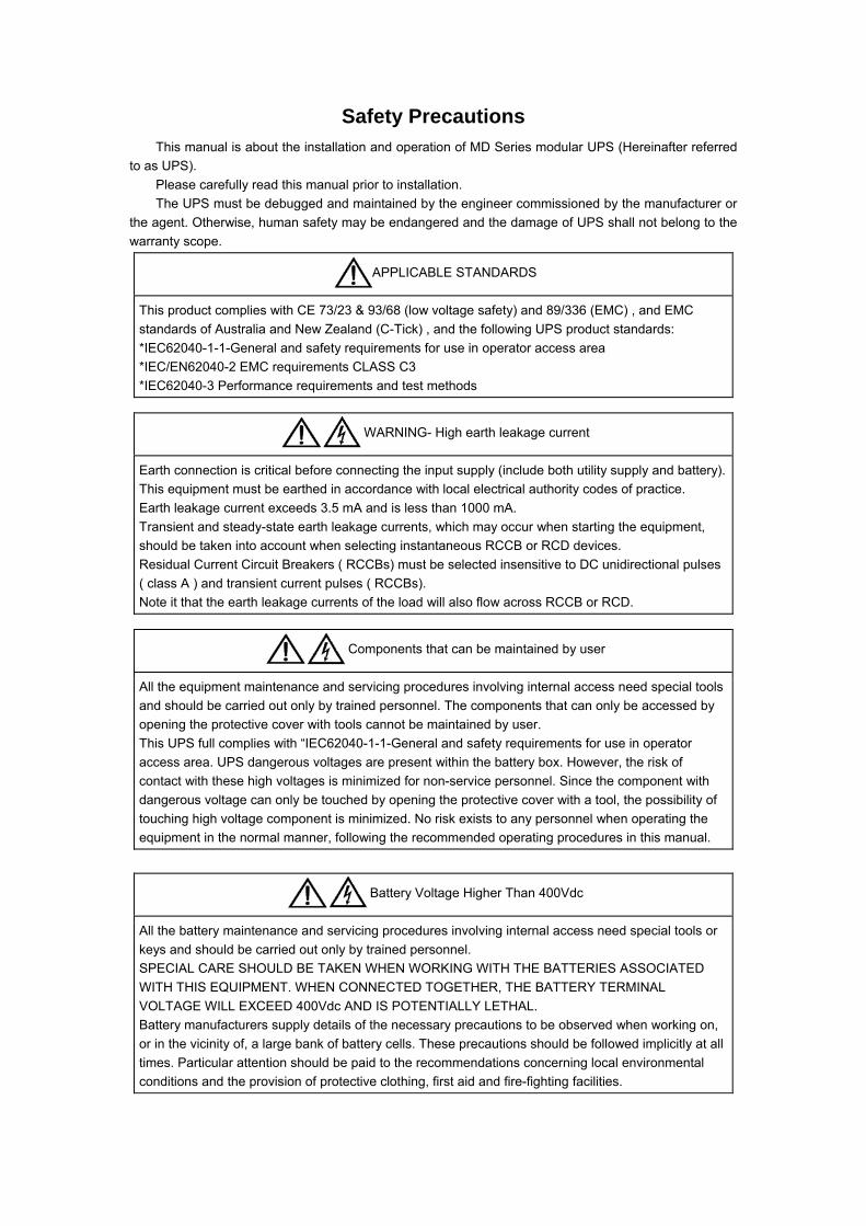
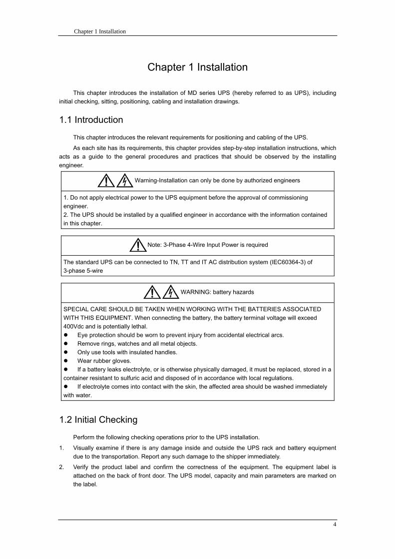
Chapter 1 Installation
4
Chapter 1 Installation
This chapter introduces the installation of MD series UPS (hereby referred to as UPS) including
initial checking sitting positioning cabling and installation drawings
11 Introduction
This chapter introduces the relevant requirements for positioning and cabling of the UPS
As each site has its requirements this chapter provides step-by-step installation instructions which
acts as a guide to the general procedures and practices that should be observed by the installing
engineer
Warning-Installation can only be done by authorized engineers
1 Do not apply electrical power to the UPS equipment before the approval of commissioning
engineer
2 The UPS should be installed by a qualified engineer in accordance with the information contained
in this chapter
Note 3-Phase 4-Wire Input Power is required
The standard UPS can be connected to TN TT and IT AC distribution system (IEC60364-3) of
3-phase 5-wire
WARNING battery hazards
SPECIAL CARE SHOULD BE TAKEN WHEN WORKING WITH THE BATTERIES ASSOCIATED
WITH THIS EQUIPMENT When connecting the battery the battery terminal voltage will exceed
400Vdc and is potentially lethal
Eye protection should be worn to prevent injury from accidental electrical arcs
Remove rings watches and all metal objects
Only use tools with insulated handles
Wear rubber gloves
If a battery leaks electrolyte or is otherwise physically damaged it must be replaced stored in a
container resistant to sulfuric acid and disposed of in accordance with local regulations
If electrolyte comes into contact with the skin the affected area should be washed immediately
with water
12 Initial Checking
Perform the following checking operations prior to the UPS installation
1 Visually examine if there is any damage inside and outside the UPS rack and battery equipment
due to the transportation Report any such damage to the shipper immediately
2 Verify the product label and confirm the correctness of the equipment The equipment label is
attached on the back of front door The UPS model capacity and main parameters are marked on
the label
Chapter 1 Installation
5
13 Positioning
131 Distribution Room
The UPS is designed for indoor installation which shall be located in a clean environment with
adequate ventilation to keep the environmental temperature within the required specification The UPS
uses forced convection cooling by internal fans Cooling air enters the module through ventilation grills
located at the front part of the cabinet and exhausted through grills located in the rear part of the cabinet
Please do not block the ventilation holes
If necessary a system of extractor fans should be installed to aid cooling-air flow An air filter should
be used when the UPS is to operate in a dirty environment and should be regularly cleaned to maintain
airflow
Note The UPS should be installed on a cement surface or other surface that is not
combustible
132 Battery Room
The battery will generate some amount of hydrogen and oxygen at the end of charging so the
fresh air volume of the battery installation environment must meet EN50272-2001 requirements The
ambient temperature of the battery must be stable Ambient temperature is a major factor in determining
the battery capacity and life The nominal operating temperature of battery is 20degC Operating above this
temperature will reduce the battery life and operation below this temperature will reduce the battery
capacity If the average operating temperature of battery is increased from 20ordmC to 30ordmC then the
service life of the battery will be reduced by 50 If the operating temperature of the battery is above
40ordmC then the battery service life will be decreased in exponent rate In a normal installation the battery
temperature is maintained between 15degC and 25degC Keep batteries away from heat sources or air
outlets
If external batteries are to be used a battery protection device (a DC circuit breaker) must be
mounted as close as possible to the batteries and the connecting cables should be as short as possible
133 Storing
If the equipment is not installed immediately it must be stored in a room so as to protect it against
excessive humidity and heat sources The battery needs to be stored in dry and cool place with good
ventilation The most suitable storage temperature is 20 ordmC to 25ordmC
14 Disassembly Initial Checking and Positioning
Check the packaging first upon the arrival of product to see if there is any damage open the
packaging to check the equipment report any such damage to the shipper immediately
141 System Packaging
Open the wooden case first the open method is shown in fig 1-1
Chapter 1 Installation
6
Fig 1-1 Open method
Firstly open the top plate of the steel-edged wooden case with slotted awl and plier followed by
sideboards Be careful not to scratch the product See fig 1-2
Fig 1-2 Disassemble the case
Take out the foam after disassembling the sideboards of the case as shown in fig 1-3
Chapter 1 Installation
7
Fig 1-3 Complete the disassembly
Tip Dismantle the bolt that connects the cabinet and wooden pallet after disassembly then lift the
cabinet to installation position The dismantlement should be careful so as not to scratch the body
Verify the product label and confirm the correctness of the equipment The equipment label is
attached on the back of front door The UPS model capacity and main parameters are marked on the
label
142 Module Packaging
The open method is shown in fig 1-4
The packing case should be placed horizontal and stable
Fig 1-4 Open method
Cut the plastic packing belt and scotch tape to open the carton see fig 1-5
Chapter 1 Installation
8
Fig 1-5 Open the carton
Open the foamed cover the equipment with plastic package can be see as shown in fig 1-6
Fig 1-6 Open the foamed cover
At last take out the equipment with plastic package and dismantle the packaging materials
Warm Tips Please dispose the wasted materials in accordance with environmental
protection requirements after disassembly
To prolong the service life the place chosen for the UPS must guarantee
Easy wiring
Sufficient space for operation
CartonFoamed package
Carton
Equipment
Top cover of foamed package
Foamed package
Chapter 1 Installation
9
Air sufficient enough to dispel heat produced by UPS
Against ambient corrosive gases
Against excessive humidity and heat sources
Against dust
With the current fire prevention requirements
The operating environment temperature is within 20~25 The batteries are at maximum
efficiency in this temperature range (for information about the battery storage and transportation as
well as the environment please refer to table 6-2)
143 UPS Composition
UPS composition shall refer to fig 1-7 UPS configuration shall refer to table 1-1
功率模块
旁路模块
开关单元 配电单元
2m cabinet (front view) 2m cabinet (back view)
Bypass module
Power module
Distribution
unit
Switch unit
Chapter 1 Installation
10
开关单元
旁路模块
功率模块
配电单元
16m cabinet (front view) 16m cabinet (back view)
Fig 1-7 UPS Composition Diagram
Table 1-1 UPS Configuration Table
Involved part name Quantity (Piece) Note
Cabinet
Switch PDU 1 Standard configuration
Monitoring + bypass
module 1 Standard configuration
Power module Power module 1~6 or 1~10
Field installation is
required
144 Operation Space
As UPS has no ventilation grills at either sides no clearances are required for the sides
To enable routine tightening of power terminations within the cabinet it is recommended that
clearance around the front and back of the equipment should be sufficient to enable free passage of
personnel with the doors fully opened
145 Front and Back Access
The component layout of the UPS supports front and back access for servicing diagnosing and
repairing the UPS thus reducing the space requirement for side access
146 Final Positioning
When the equipment has been finally positioned ensure the adjustable feet are set so that the UPS
will remain stationary and stable
147 Power Module Installation
The installation position of power module and output distribution module are shown in fig 1-8 the
installation principle of these module is to installed from bottom to top to prevent inclination of the cabinet
due to high center of gravity
As is shown in fig 1-8 the installation procedure of power module is as follows
Switch unit
Bypass module
Power module
Distribution unit
Chapter 1 Installation
11
1 Each module shall be installed from bottom to top the default setting of the system is module No 1
2 3 4 5 6 7 8 9 and 10
2 Insert the module into installation position and push in the cabinet The wiring terminals in between
shall be tight and excessive force shall be prevented against the damage to inserted pins of the
terminals
3 Fix the module to the cabinet though the mounting holes on two sides of the front plate of the
module
固定孔
A处放大
Fig 1-8 Power Module Installation Diagram
148 Cable Entry
Cables can enter the UPS from top and below as shown in fig 1-9 Both the top and bottom of the
UPS have cable entrance
The recommended installation practice is to install power cables in the entrance channel
at both sides of the cabinet back door so as not to affect the ventilation
进线通道 进线通道
Fig 1-9 Cable Entry Diagram
Power module
Fixing hole
Amplification of A
Cable entrance Cable entrance
Chapter 1 Installation
12
15 Protective Devices
For safety concerns it is recommended to install external circuit breakers or other protective devices
for the input AC supply of the UPS system This section provides generic practical information for
qualified installation engineers The installation engineers should have the knowledge of the regulatory
wiring standards and of the equipment to be installed
151 Rectifier and Bypass Input Supply of the UPS
Install suitable protective devices in the distribution unit of the incoming mains supply considering
the power cable current-carrying capacity and overload capacity of the system (see Table 1)Generally
the magnetic circuit breaker with IEC60947-2 tripping curve C (normal) at the 125 of the current listed
in table 1-1 is recommended
Note
For IT power network system 4-pole protective device must be installed on the external input
distribution of the UPS
If protection against earth faults (RCD devices) is required for the upstream of the input supply the
installed device should
Sensitive to DC unidirectional pulses (class A) in the network
Insensitive to transient current pulses
Have an average sensitivity that is adjustable between 03A~1A
The RCCB must be sensitive to DC unidirectional pulses (class A) in the network while insensitive
to transient current pulses as shown in fig 1-10 respectively
Fig 1-10 RCCB sign
152 Battery
A battery unit is composed of 40 batteries connected in series a centreline is drawn from in
between (the joint part between the 20th and 21st battery) plus the line drawn from the front and back
there are altogether 3 lines connected with UPS line contact bank The battery line must push through a
DC circuit breaker before connecting to corresponding UPS line contact bank The detailed wiring please
refer to fig 1-11 below
Fig 1-11 Diagram of batteries connected in series
40 batteries connected in series
Chapter 1 Installation
13
153 UPS Output
A main output switch has been installed in UPS the user shall install the over current protective
device on the bypass of each output of the external distribution cabinet
16 Power Cables
Design the cables according to the descriptions in this section and local regulatory wiring standards
and the environmental conditions should be taken into consideration Refer to IEC60950-1 Table 3B
Warning
Prior to cabling the UPS confirm the status and positions of the switches of the UPS rectifier input
power supply bypass power supply and mains power distribution board
Ensure that these switches are opened and attached with WARNING label so as to prevent
unauthorized operation to these switches
161 Maximum stable state current and configuration of cable system please refer to
table 1-2
Table 1-2 Maximum stable state current and configuration of cable system
System Name MD-06010 MD-09015 MD-12020 MD-10010 MD-15015 MD-20020
Capacity
System
capacity 60kVA 90kVA 120kVA 100kVA 150kVA 200kVA
Module
capacity 10kVA 15kVA 20kVA 10kVA 15kVA 20kVA
Cabinet
dimension 6009001600(WDH mm) 6009002000(WDH mm)
Main
Input
Rated
current A 90 136 180 150 227 300
Cable mm2 25 35 50 50 75 75
Output
Rated
current A 90 136 180 150 227 300
Cable mm2 25 35 50 50 75 75
Battery
Rated
current A 106 160 212 178 265 355
Cable mm2 35 50 75 50 75 90
PE Cable mm2 35 50 75 50 75 90
Warning
FAILURE TO FOLLOW ADEQUATE EARTHING PROCEDURES CAN RESULT IN EMI ELECTRIC
SHOCK HAZARD OR RISK OF FIRE
Chapter 1 Installation
14
162 Cable Connection
Note
The operations described in this section must be performed by authorized electricians or qualified
technical personnel If you have any difficulties do not hesitate to contact our Customer Service amp
Support department at the address given at the beginning of this manual
After the equipment has been finally positioned and secured connect the power cables as
described in the following procedures
1 Verify that all the external input distribution switches of the UPS are completely opened and the
UPS internal maintenance bypass switch is opened Attach necessary warning signs to these
switches to prevent unauthorized operation
2 Open the back door of the cabinet remove the cover and then the input and output terminal
battery terminal and earth terminal are visible
3 Connect the input earth wire to input earth terminal Please note the earth wire shall be connected
in accordance with related local or state regulation
4 For common bypass and rectifier inputs connect the AC input supply cables to the UPS input
terminals (Main input A-B-C-N) and connect the output loaded cable to the UPS output terminals
(Output A-B-C-N) and tighten the connections to 13 Nm (M8 Bolt) ENSURE CORRECT PHASE
ROTATION
5 Connect the battery cables between the UPS battery terminals and battery switch ENSURE
CORRECT PHASE ROTATION
Warning-Hazardous battery terminal voltage of 400Vdc
Ensure the correct polarity connection between the battery terminals and the UPS terminals Positive
terminal to positive terminal negative terminal to negative terminal and disconnect one or more than
one cable between every two layers of batteries Do not connect the cables and close the battery
circuit breakers before getting the approval from the commissioning engineer
6 Re-install all the protective covers
17 Control and Communication Cabling
As shown in fig 1-12 the front panel of the bypass module will provide dry contact interface
(J2~J10) communication interface (RS232 485 and SNMP card interface) as well as LBS interface
干接点接口
SNMP卡接口
RS485接口
RS232接口LBS接口
Fig 1-12 Dry contact interface and communication interface
Dry contact
interface
SNMP card port
LBS port RS232 port
RS485 port
Chapter 1 Installation
15
The UPS accepts external signal from zero-voltage (dry) contacts connected through external dry
contact terminals produced and phoenix terminals that are in bypass module Through software
programming these signals become active when these contacts connect to +24V to ground)The cables
connected to DRY terminal must be separated from power cables Moreover these cables should be
double insulated with a typical 05 to 15 mm2
cross-section area for a maximum connection length
between 25 and 50 meters
171 Dry Contact Interface of Battery and Environmental Temperature Detection
The input dry contact J2 and J3 can detect the temperature of batteries and environment
respectively which can be used in environment monitoring and battery temperature compensation 1
J2 and J3 interfaces diagram are shown in fig 1-13 the description of interface is in table 1-3
Fig 1-13 Diagram of J2 and J3 dry contact for temperature detecting
Table 1-3 Description of input dry contact interface J2 and J3
Position Name Purpose
J21 TEMP_BAT Battery temperature detection
J22 GND Power ground
J31 TEMP_ENV Environment temperature detection
J32 GND Power ground
Note Specified temperature sensor is required for temperature detection (R25=5Ohm
B2550=3275) please confirm with the manufacturer or contact local maintenance engineers when
placing an order
172 Remote EPO Input Port
The UPS has an Emergency Power OFF (EPO) function This function can be activated by pressing
a button on the control panel of the UPS or through a remote contact provided by the user The EPO
pushbutton is protected by a hinged plastic cover
J4 is the input port for remote EPO It requires shorting NC and +24v during normal operation and
the EPO is triggered when opening NC and +24v or shorting NO and +24v The port diagram is shown in
fig 1-14 and port description is shown in table 1-4
Chapter 1 Installation
16
Fig 1-14 Diagram of input port for remote EPO
Table 1-4 Description of input port for remote EPO
Position Name Purpose
J41 EPO_NC EPO is activated when disconnecting fromJ42
J42 +12V +24V connect the common terminal of NC and NO
J43 +12V EPO is activated when shorting with J42
The EPO is triggered when shorting pin 2 and 3 or opening pin 2 and 1 of J4
If an external emergency stop facility is required it is connected via the reserved terminals of J4
The external emergency stop facility needs to use shielded cables to connect to the normally
openclosed remote stop switch between these two pins If this facility is not used then pin 3 and pin 4 of
J4 must be open or pin 1 and pin 2 of J4 must be shorted
Note
1 The emergency stop action within the UPS will shut down the rectifier inverter and static bypass
However it does not internally disconnect the mains input power supply To disconnect ALL power to
the UPS open the upstream input circuit breaker(s) when the EPO is activated
2 Pin 1 and 2 of J4 have been shorted before the UPS is delivered
173 Generator Input Dry Contact
J5 is status interface for generator connection Connect pin 2 of J5 with + 24 power supply it
indicates that the generator has been connected with the system The interface diagram is shown in fig
1-15 and interface description is shown in table 1-5
Chapter 1 Installation
17
Fig 1-15 Diagram of status interface and connection of generator
Table 1-5 Description of maintenance bypass switch and output switch status interface
Position Name Purpose
J51 +24V +24V power supply
J52 GEN Connection status of generator
J53 GND Power ground
174 BCB Input Port
J6 and J7 are the ports of BCB The port diagram is shown in fig 1-16 and description is shown in
table 1-6
BC
B_D
RV
BC
B_C
ON
T
J6 J7
BC
B_O
NL
+24V+24V
+24V
Fig 1-16 BCB Port
Table 1-6 Description of BCB port
Position Name Description
J61 BCB_DRV BCB actuating signal provide the actuating signal of +18V 20mA
J62 BCB_CONT BCB contact status connect with the normally open signal of BCB
J71 GND Power ground
J72 BCB_ONL BCB on-linendashinput (normally open) BCB is on-line when the signal
is connecting with GND
175 Battery Warning Output Dry Contact Interface
J8 is the output dry contact interface which outputs the battery warnings of low or excessive
voltage when the battery voltage is lower than set value an auxiliary dry contact signal will be
provided via the isolation of a relay The interface diagram is shown in fig 1-17 and description is
shown in table 1-7
Generator
Chapter 1 Installation
18
Fig 1-17 Battery warning dry contact interface diagram
Table 1-7 Battery warning dry contact interface description Position Name Purpose
J81 BAT_LOW_NC Battery warning relay (normally closed) will be open during warning
J82 BAT_LOW_NO Battery warning relay (normally open) will be closed during warning
J83 GND Center of battery warning relay
176 Integrated Warning Output Dry Contact Interface
J9 is the integrated warning output dry contact interface when one or more than one preset
warning is triggered the system will send an integrated warning information and provide an auxiliary
dry contact signal via the isolation of a relay The interface diagram is shown in fig 1-18 and description
is shown in table 1-8
Fig 1-18 Integrated warning dry contact interface diagram
Table 1-8 Integrated warning dry contact interface description Position Name Purpose
J91 ALARM_NC Integrated warning relay (normally closed) will be open during warning
J92 ALARM_NO Integrated warning relay (normally open) will be closed during warning
J93 GND Centre of integrated warning relay
177 Mains Failure Warning Output Dry Contact Interface
J10 is the output dry contact interface for mains failure warning when the mains fails the system
will send a mains failure warning information and provide an auxiliary dry contact signal via the isolation
of a relay The interface diagram is shown in fig 1-19 and description is shown in table 1-9
Chapter 1 Installation
19
Fig 1-19 Mains failure warning dry contact interface diagram
Table 1-9 Mains failure warning dry contact interface description Position Name Purpose
J91 UTI_FAIL_NC Mains failure warning relay(normally closed) will be open during
warning
J92 UTI_FAIL_NO Mains failure warning relay normally open) will be closed during
warning
J93 GND Centre of mains failure warning relay
178 RS232 Port and SNMP Card Port
RS232 and RS485 Port provide serial data which can be used for commissioning and maintenance
by authorized engineers or maintainers or can be used for networking or integrated monitoring system in
the service room
SNMP Card Port used for field installation of the communication option card(SNMP card)
179 LBS (Load Bus Synchronizer) Port
The dual bus system (DBS) consists of two independent UPS rack module systems as shown in fig
1-20 The dual bus system is configured for high availability and is suitable for powering the load with
dual inputs If the load is single-input load the static transfer switch and LBS control is recommended to
maintain both UPS outputs synchronized for uninterrupted transfers Please install the system according
to the installation descriptions for different system configurations
The dual bus system is supported by UPS it requires connecting the LBS signal cables of two UPS
when constructing the dual bus system please refer to relevant chapter for detailed configuration and
installation and the system software shall be configured as required
UPS 1
LBS
监控旁路模块 UPS 2
LBS
监控旁路模块
Fig 1-20 LBS Connection Diagram
18 Installation Drawing
Please refer to fig 1-21 fig 1-22 fig 1-23 and fig 1-24
UPS 1 monitoring bypass module
UPS 2 monitoring bypass module
Chapter 1 Installation
20
Fig 1-21 Installation Diagram
Chapter 1 Installation
21
顶视图
2m cabinet front view
16 m cabinet (front view)
Fig 1-22 UPS front view (Unit mm)
Top view
Chapter 1 Installation
22
A
2m cabinet
A
16m cabinet
Fig 1-23 UPS back view
Chapter 1 Installation
23
A
A处放大
Fig 1-24 UPS front view
Amplification of A
24 Chapter 2 Operations
24
Chapter 2 Operations
This chapter introduces the basic knowledge of UPS operations including working principle
operation mode battery management and protection
Warning Hazardous mains voltage andor battery voltage present(s)behind the protective cover
The components that can only be accessed by opening the protective cover with tools cannot be
operated by user
Only qualified service personnel are authorized to remove such covers
21 Introduction
UPS provides the critical load (such as communication and data processing equipment) with high
quality uninterruptible AC power The power from UPS is free from voltage and frequency variations and
disturbances (interruption and spike) experienced at the Mains AC input supply
This is achieved through high frequency double conversion power pulse width modulation (PWM)
associated with full digital signal processing control (DSP) which features high reliability and
convenience for use
211 Principle
As shown in fig 2-1 the AC input mains source is supplied at UPS input and converted into a DC
source This DC source feeds the Inverter that converts the DC source into a clean and input
independent AC source The battery powers the load through the inverter in case of an AC input mains
power failure The utility source can also power the load through the static bypass
When the UPS needs maintenance or repair the load can be transferred to maintenance bypass
without interruption and the power module and bypass module can be removed for maintenance
Chapter 2 Operations 25
25
Fig 2-1 System principle framework
212 Bypass Module
The circuit blocks labeled ldquobypass modulerdquo in fig 2-1 contain electronically controlled switching
circuits that enable the critical load to be connected to either the inverter output or to a bypass power
source via the static bypass line During normal system operation the load is connected to the inverter
but in the event of a UPS overload or inverter failure the load is automatically transferred to the static
bypass line
To provide a clean (no-break) load transfer between the inverter output and static bypass line the
inverter output and bypass supply must be fully synchronized during normal operating conditions This is
achieved through the inverter control electronics which makes the inverter frequency track that of the
static bypass supply provided that the bypass remains within an acceptable frequency window
A manually controlled maintenance bypass supply is incorporated into the UPS design It enables
the critical load to be powered from the utility (bypass) supply while the UPS is shut down for routine
maintenance
Note
When the UPS is operating in bypass mode or on maintenance bypass the connected equipment is
not protected from power failures or surges and sags
22 Operation Mode
The MD UPS is an on-line double-conversion reverse-transfer UPS that permits operation in these
modes
Normal mode
26 Chapter 2 Operations
26
Battery mode
Auto-Restart mode
Bypass mode
Maintenance mode (manual bypass)
ECO mode
Frequency converters mode
221 Normal Mode
The UPS inverter power modules continuously supplies the critical AC load The rectifiercharger
derives power from the AC mains input source and supplies DC power to the inverter while
simultaneously FLOAT or BOOST charging its associated backup battery
222 Battery Mode
Upon failure of the AC mains input power the inverter power modules which obtains power from the
battery supplies the critical AC load There is no interruption in power to the critical load upon failure
After restoration of the AC mains input power the ldquoNormal Moderdquo operation will continue automatically
without the necessity of user intervention
Note UPS can also be started through battery (charged) mode via battery cold start function upon
failure of the AC mains Therefore the battery power can be used independently to improve the
utilization rate of UPS
223 Auto-Restart Mode
The battery may become exhausted following an extended AC mains failure The inverter shuts
down when the battery reaches the End of Discharge voltage (EOD) The UPS may be programmed to
ldquoAuto Recovery after EODrdquo after a delay time if the AC mains recovers This mode and any delay time
are programmed by the commissioning engineer
During the process of delay time the battery will be charged by UPS to prevent any risks to load
equipment from future mains failure
224 Bypass Mode
If the inverter overload capacity is exceeded under normal mode or if the inverter becomes
unavailable for any reason the static transfer switch will perform a transfer of the load from the inverter
to the bypass source with no interruption in power to the critical AC load
225 Maintenance Mode
A manual bypass switch is available to ensure continuity of supply to the critical load when the UPS
becomes unavailable eg during a maintenance procedure
Note This manual bypass switch is fitted in all UPS modules Transfer UPS system to bypass
module for power supply first then close maintenance bypass switch Q2 followed by Q1 and Q3
Warning hazard may occur after transferring to maintenance bypass
After UPS being transferred to maintenance bypass power module and bypass module do not work
no display on LCD and input and output terminals as well as N bus are electrically connected
Chapter 2 Operations 27
27
226 ECO Mode
If economical (ECO) mode is selected the double-conversion UPS will stop to work so as to save
energy During the operation of ECO mode the load power will be supplied by bypass preferentially
When bypass power is within the range of normal frequency and voltage load power will be supplied by
bypass or the system will transfer to inverter input followed by load power interruption which extends
within 34 of the utility period Eg when the frequency is 50Hz the interruption time will be less than
15ms when the frequency is 60Hz the time will be less than 125ms
227 Frequency Converters Mode
If the frequency converter configuration is used by UPS it will provide 50Hz or 60Hz stable output
frequency The range of output frequency is 40Hz~70Hz Under this mode static bypass is unavailable
but battery can be selected according to the actual requirements of battery mode
23 Battery Management
231 Normal Function
The following functions should be fitted by commissioning engineers with specified software
1 Constant current boost charging
Current can be set up
2 Constant voltage boost charging
Voltage of boost charging can be set as required by the type of battery
For Valve Regulated Lead Acid (VRLA) batteries maximum boost charge voltage should not
exceed 24V cell
3 Float charge
Voltage of float charging can be set as required by the type of battery
For VRLA float charge voltage should be between 22V to 23V
4 Float charge temperature compensation (optional)
A coefficient of temperature compensation can be set as required by the type of battery
5 End of discharge (EOD) protection
If the battery voltage is lower than the EOD the battery converter will shut down and the battery is
isolated to avoid further battery discharge EOD is adjustable from 16V to 175V per cell (VRLA) or 09
to 11 V per cell
6 Battery low warning time
It is adjustable between 3 and 60 minutes The default is 5 minutes
232 Advanced Functions (Battery Self-checking and Maintenance)
At periodic intervals 20 of the rated capacity of the battery will be discharged automatically and
the actual load must exceed 20 of the rated UPS (KVA) capacity If the load is less than 20
auto-discharge cannot be executed The periodic interval can be set from 30 to 360 days The battery
self-test can be disabled
ConditionsmdashBattery at float charge for at least 5 hours load equal to 20~100 of rated UPS capacity
TriggermdashManually through the command of ldquoBattery Maintenance Testrdquo in LCD panel or automatically
Battery Self-Test Intervalmdash30-360 days (default setting is battery self-test disabled)
28 Chapter 2 Operations
28
24 Battery Protection
The following functions should be fitted by commissioning engineers with specified software
1 Battery Low Pre-warning
The battery under voltage pre-warning occurs before the end of discharge After this pre-warning
the battery should have the capacity for 3 remaining minutes discharging with full load The time is user
configured from 3 to 60 minutes
2 Battery discharge (EOD)off protection
If the battery voltage is lower than the EOD the battery converter will be shut down EOD is
adjustable from 16V to 175V per cell (VRLA) or 09 to 11 V per cell (NiCd)
3 Battery Circuit Breaker (BCB) Alarm
The alarm occurs when the battery disconnect device disconnects The external battery connects to
the UPS through the external battery circuit breaker The circuit breaker is manually closed and tripped
by the UPS control circuit
Chapter 3 Operation Instructions 29
29
Chapter 3 Operating Steps
This chapter describes UPS operation instructions in detail
All functional keys and LED display involved in operation instructions please refer to chapter 4
During operation the buzzer alarm may occur at any time Select ldquomuterdquo on LED to muffle the audible
alarm
Warning-Hazardous mains voltage andor battery voltage present(s)behind the protective cover
1 The components that can only be accessed by opening the protective cover with tools cannot be
operated by user
2 Only qualified service personnel are authorized to remove such covers
31 Power Switches
As shown in fig 3-1 open the front door of UPS the power switch is visible which includes input
switch output switch and maintenance bypass switch (with anti-misoperation stop plate)
输入开关 输出开关
维修旁路开关
Fig 3-1 Power switch location diagram
32 UPS Start-up
The UPS system only has a maintenance bypass isolating switch and all the other transfers are
processed automatically by internal control logics
Input switch Output switch
Maintenance bypass switch
30 Chapter 3 Operating Instructions
30
321 Normal Module Start
This procedure must be followed when turning on the UPS from a fully powered down condition
The operating procedures are as follows
Warning
This procedure results in mains voltage being applied to the UPS output terminals If any load
equipment is connected to the UPS output terminals please check with the load user that it is safe to
apply power If the load is not ready to receive power then ensure that it is safely to close the output
switch of external distribution cabinet
1 Close UPS output switch and input switch in turns
The LCD starts up at this time The Rectifier indicator flashes during the startup of rectifier The
rectifier enters normal operation state and after about 30s the rectifier indicator goes steady green After
initialization the bypass static switch closes The UPS Mimic LEDs will indicate as shown in table 3-1
Table 3-1 Indicator status
LED Status
Rectifier indicator Green
Battery indicator Red
Bypass indicator Green
Inverter indicator Off
Load indicator Green
Status indicator Green
Note
The output circuit breaker must be closed first followed by input circuit breaker or the rectifier cannot
be started and alarm ldquorectifier failurerdquo
The inverter starts up at this time the inverter indicator flashes After the rectifier enters normal
operation state UPS power supply will transfer from bypass to inverter then the bypass indicator turns
off and load indicator lights The status of indicators is shown in table 3-2
Table 3-2 Indicator Status
LED Status
Rectifier indicator Green
Battery indicator Red
Bypass indicator Off
Inverter indicator Green
Load indicator Green
Status indicator Green
Close external battery switch again battery indicator turns off a few minutes later the battery will be
charged by UPS which will enter normal mode operation The indicator status is shown in table 3-3
Table 3-3 Indicator status
LED Status
Rectifier indicator Green
Battery indicator Green
Bypass indicator Off
Inverter indicator Green
Load indicator Green
Status indicator Green
322 Operating steps of Battery cold Start
1 Check if the batteries have been connected close the external battery switch
Chapter 3 Operation Instructions 31
31
2 Press the red start-up button of battery under the rectifier input circuit breaker for 3 seconds (see fig
3-2)
The LCD starts up at this time The green battery indicator flashes The rectifier enters normal
operation states and after about 30s the battery indicator goes steady green
3 The inverter starts up automatically the green inverter indicator flashes The output of inverter
appears after 60s The UPS works on battery mode
32 Chapter 3 Operating Instructions
32
电池启动按钮
Fig 3-2 Position diagram of battery startup button
Battery startup button
Chapter 3 Operation Instructions 33
33
33 Procedure for Switching between Operation Modes
331 Procedure for Switching the UPS into Battery mode from Normal Mode
Open input switch to cut off the mains UPS enters the battery mode If UPS should be switched to
normal mode wait for a few seconds before close input switch so as to supply the mains again 10s
later the rectifier will start up automatically to supply power to the inverter
332 Procedure for Switching the UPS into Bypass mode from Normal Mode
Select ldquoTran Byprdquo on the LCD or press ldquooffrdquo buttons of each power module in turn
Note
In bypass mode the load is directly fed by the mains power instead of the pure AC power from the
inverter
333 Procedure for Switching the UPS into Normal from Bypass Mode
Select exit bypass mode on the LCD
334 Procedure for Switching the UPS into a Maintenance Bypass from Normal Mode
In normal operation this operation instruction will switch the load from inverter input to maintenance
bypass
Caution
Before making this operation read messages on display to be sure that bypass supply is regular and
the inverter is synchronous with it so as not to have a risk of a short interruption in powering the load
1 Press ldquoTran Byprdquo on the LCD or press ldquooffrdquo on each power module in turns
If press rdquoTran Byprdquo on the LCD the inverter indicator will flash green and the buzzer will alarm
If press ldquooffrdquo on each power module in turns the inverter indicator will go off and the buzzer will
alarm
The load will be transferred to static bypass and the inverter is closed
2 Close maintenance bypass switch Q2 the load power will be supplied by maintenance bypass and
then open the inverter circuit breaker Q1 output switch Q3 and battery switch
Warning
If you need to maintain the module wait for 10 minutes to let the DC bus capacitor fully discharge
before removing corresponding module
335 Procedure for Switching the UPS into Normal from a Maintenance Bypass Mode
This procedure can transfer the load to normal main mode when the UPS is operating under the
maintenance bypass mode
1 Close output switch Q3 and main switch Q1
The bypass indicator goes green and the load power will be supplied by bypass and maintenance
bypass
2 Open maintenance bypass switch Q2
34 Chapter 3 Operating Instructions
34
The load power is supplied by bypass In the meantime the rectifier starts up rectifier indicator goes
green 30s later at this time the inverter will start up automatically and transfer to inverter mode 1 min
later automatically
3 Close external battery switch the battery indicator goes off Check if the battery voltage on LCD
display is normal
34 Procedure for Completely Powering down a UPS
If you need to power down the UPS completely follow the procedures in section 334 to transfer the
UPS from normal mode to maintenance bypass mode
If you need to isolate the UPS from the AC power supply you should open the external input switch
35 EPO Procedure
The EPO button on UPS operator control and display panel is designed to switch off the UPS in
emergency conditions (eg fire flood etc)To achieve this just press the EPO button and the system
will turn off the rectifier inverter and stop powering the load immediately (including the inverter and
bypass output) and the battery stops charging or discharging
If the input utility is present the UPS control circuit will remain active however the output will be
turned off To completely isolate the UPS you need to open the external mains input supply to the UPS
rack
36 Language Selection
The LCD is available in two languages Chinese English and Korean
The language can be selected through LCD prompt window
37 Control Password
When the LCD displays ldquoinput control password 1rdquo the initial password is 12345678
Chapter 4 Operator Control and Display Panel 35
35
Chapter 4 Operator Control and Display Panel
This chapter introduces the functions and operation instructions of the parts on UPS operator control
and display panel in detail and provides LCD display information including LCD display types detailed
menu information prompt window information and UPS alarm list
41 Introduction
The operator control and display panel is located on the front panel of the UPS Through this LCD
panel the operator can operate and control the UPS and check all measured parameters UPS and
battery status and event and alarm logs The operator control panel is divided into three functional areas
as shown in fig 4-1 mimic current path LCD display amp Menu keys and Control and Operation Keys The
detailed description of parts on operator control and display panel is shown in table 4-1
Fig 4-1 UPS operator control and display panel
Table 4-1 Description of UPS operator control and display panel
Part No Function Button Function
REC Rectifier indicator EPO EPO switch
BAT Battery indicator TAB switch
BYP Bypass indicator ENTER confirm
INV Inverter indicator ESC exit
OUTPUT Load indicator
STATUS Status indicator
36 Chapter 4 Operator Control and Display Panel
36
411 LED Indicator
The LEDs shown on the mini current path represent the various UPS power paths and show the
current UPS operating status The status description of indicators is shown in table 4-2
Table 4-2 Status description of indicator
Indicator State Purpose
Rectifier
indicator
Steady green Rectifier normal for all modules
Flashing green Rectifier for at least on module normal mains normal
Steady red Rectifier fault
Flashing red Mains abnormal for at least one module
Off Rectifier not operating
Battery
indicator
Steady green Battery charging
Flashing green Battery discharging
Steady red
Battery abnormal (battery failure no battery or battery reverse) or
battery converter abnormal (failure over current or over temperature)
EOD
Flashing red Battery low voltage
Off Battery and battery converter normal battery not charging
Bypass
indicator
Steady green Load power supplied by bypass
Steady red Bypass power abnormal or out of normal range or static bypass
switch fault
Flashing red Bypass voltage abnormal
Off Bypass normal
Inverter
indicator
Steady green Load power supplied by inverter
Flashing green Inverter On start synchronization of standby (ECO mode) for at least
one module
Steady red System power not supplied by inverter inverter fault for at least one
module
Flashing red System power supplied by inverter inverter fault for at least one
module
Off Inverter not operating for all modules
Load
indicator
Steady green UPS output ON and normal
Steady red UPS output overload and overtime or output short or output no power
supply
Flashing red Overload output of UPS
Off No output of UPS
Status
indicator
Steady green Normal operation
Steady red Failure
412 Audible Alarm (buzzer)
There are two different types of audible alarm during UPS operation as shown in table 4-3
Table 4-3 description of audible alarm
Alarm Purpose
Two short alarm with
a long one
when system has general alarm (for example AC fault) this audible alarm
can be heard
Continuous alarm When system has serious faults (for example fuse or hardware fault) this
audible alarm can be heard
Chapter 4 Operator Control and Display Panel 37
37
413 Functional Keys
There are 4 functional keys on operator control and display panel which are used together with LCD
The functions description is shown in table 4-4
Table 4-4 Functions of functional keys
Functional key Functions
EPO switch To cut off the load power to shut down the rectifier inverter static
bypass and battery
TAB switch
ENTER confirm
ESC exit
42 LCD Display Type
Following the self-check of UPS LCD display the main LCD display is shown as fig 4-2 which can
be divided into three display windows system information data command and current record
Fig 4-2 Main LCD display
The description of LCD icon is shown in table 4-5
Table 4-5 Description of LCD icons
Icon Description
Bypass parameter
UPS system
information
window
Data
command
window
Current
record
window
38 Chapter 4 Operator Control and Display Panel
38
Icon Description
Main input parameter
History file system information
Function setting (display calibration password setting time setting date format
communication protocol and language setting) system setting (used by product
maintainers)
Battery data battery parameter setting (used by service staff)
Test (battery self-test battery maintenance)
Functional keys used by service staff (fault clearing history file clearing noise
clearing manual switch of bypass) userrsquos setting (system mode machine
number system ID output voltage adjustment frequency tracing speed
frequency tracing limit)
Output parameter
Load
Noise clearing noise clearing cancel
Log view page updown
Select a icon on LCD as shown in fig 4-3 to view the UPS parameter represented by this icon eg
select the LCD will display the data of system main input
Chapter 4 Operator Control and Display Panel 39
39
Fig 4-3 Select data
Or select and confirm a module as shown in fig 4-4 the LCD will display the
operating status of this module
Fig 4-4 Select a module
40 Chapter 4 Operator Control and Display Panel
40
Select in the operating status of a module to view the main input data of this module
Select in the operating status of a module to view the main output data of this module
Select in the operating status of a module to view the load data of this module
Select in the operating status of a module to view the maintenance code and module
software code of this module
Select to return to the previous page
Select to return to the home page
Default display
During the operation of system if therersquos no alarm in 2 min the system will display default After a
short delay the backlight of LCD display goes off press any key to reactivate the display
43 Detailed Description of Menu Items
The LCD main display shown in fig 4-2 is described in details below
UPS information window
UPS information window display the current time and UPS name The information of the window is
not necessary for the user to operate The information of this window is given in table 4-6
Table 4-6 Description of items in UPS system information window
Display contents Meaning
MD12020 UPS Name
1200 Current Time (format 24 hours hours minute)
UPS menu and data window
UPS menu window displays the menu name of data window while the data window displays the
related contents of selected menu in menu window Select UPS menu and data window to browse
related parameters of UPS and set related functions The details are given in table 4-7
Table 4-7 Item description of UPS menu and data window
Menu name Menu item Meaning
Main input
V phase(V) V phase
I phase(A) I phase
Freq(Hz) Input frequency
PF Power factor
Bypass input
V phase(V) V phase
Freq (Hz) Bypass frequency
I phase(A) I phase
PF Power factor
AC output
V phase(V) V phase
I phase(A) I phase
Freq (Hz) Output frequency
PF Power factor
This UPS Sout (kVA) Sout Apparent Power
Chapter 4 Operator Control and Display Panel 41
41
Menu name Menu item Meaning
modulersquos
load
Pout (kW) Pout Active Power
Qout (kVAR) Qout Reactive Power
Load () Load (The percentage of the UPS rating load)
Battery data
Environmental
Temp Environmental Temp
Battery
voltage(V) Battery bus voltage
Battery current
A) Battery bus current
Battery
Temp() Battery Temp
Remaining Time
(Min) Remaining battery backup time
Battery capacity
() The percentage compared with new battery capacity
battery
equalized
charging
Battery is equalized charging
battery float
charging Battery is float charging
Battery
disconnected Battery is not connected
Current
record (current alarm)
Display all current alarm The alarm list displayed on LCD of
UPS operator control and display panel please refer to table 4-9
History
record (history alarm)
Display all history alarm The alarm list displayed on LCD of
UPS operator control and display panel please refer to table 4-9
Menu
Language
(language
option) 2 languages can be selected
Settings
Display
calibration Adjust the accuracy of LCD display
Date format set MM DD YYYY and YYYY MM DD formats can be selected
Date amp Time DateTime set
Language set User can set the language (Chinese and English)
Communication
mode
Set communication mode MODBUS Power protocol and
company custom protocol modes can be selected Power
protocol mode can be divided into equipment address baud
rate set MODBUS protocol mode can be divided into
communication mode (RTUASCⅡ) equipment address
baud rate and check-bit set Company custom protocol mode
is the customed protocol of the company no option is
available
Control
password set User can modify control password 1
Test
Command
(Battery Test
Control
Battery
maintenance
test
This test will lead to the battery being partly discharged to
activate battery at the same time the approximate battery
capacity will be obtained Bypass must be in normal condition
the battery capacity should be above 25
42 Chapter 4 Operator Control and Display Panel
42
Menu name Menu item Meaning
Battery
self-check test
UPS switches to battery discharge for discharging to test if the
battery is normal Bypass must be in normal condition the
battery capacity should be above 25
Stop testing Manually Stop the test including maintenance test capacity test
UPS system
information
Monitoring
software version Provide monitoring software version
Rectified
software version Provide rectified software version
Inverted
software version Provide inverted software version
Serial No The serial no set when delivery from the factory
Rated
information Network setting of system operating
Module type Type of the module
44 Alarm List
The follow table 4-8 gives the complete list of all the UPS events displayed by history record window
and current record window
Table 4-8 Alarm List
Alarm Explanation
UPS power supply The system is in normal inverted power supply status
Bypass power
supply The system is in bypass power supply status
No power supply System no output
Battery equalized
charging Battery is in boost charging
Battery float
charging Battery is in float charging
Battery discharging The system is operating in battery discharging status
Battery connected Battery is connected
Battery
disconnected Battery is not connected
Maintenance circuit
breaker close Maintenance circuit breaker is close
Maintenance circuit
breaker open Maintenance circuit breaker is open
Emergency
shutdown System emergency shutdownEPO
Generator
connected External generator is connected
Mains abnormal Input mains abnormal
Bypass phase
conversion Bypass input phase converse
Bypass voltage
abnormal Bypass input voltage abnormal
Bypass fault Bypass fault
Bypass overload Bypass output is overload
Up to bypass
overtime of Bypass is overtime of overload
Chapter 4 Operator Control and Display Panel 43
43
Alarm Explanation
overload
Bypass frequency
tracing exceeds Bypass frequency is out of the tracing range
Switch times up to
in this hour
The times of switch between bypass and inverter exceeds 5 times in the latest
hour
Output short System output short
Battery EOD Battery voltage achieves shutdown point
Battery self-check The system enters battery self-check mode
Battery self-check
success Battery normal during system self-check
Battery manual
check failure Battery fault during system self-check
Battery
maintenance The system is in battery maintenance status
Battery
maintenance
success
Battery maintenance status completes
Battery
maintenance failure Battery maintenance process is not normal
Stop testing Battery self-check or battery maintenance status stops
Fault clearing Clear the alarmed fault
Delete history
record Delete all history record
N communication
node connected N module is connected to UPS system
N communication
node disconnected N module is not connected to UPS system
N rectifier fault N module rectifier fault
N inverter fault N module inverter fault
N rectifier
overheat N module rectifier overheat
N fan fault N module fan fault
N output overload N module output overload
N overtime of
overload N module output overtime of overload
N inverter
overheat N module inverter overheat
Inverter power
supply ban Inverter power ban supply
Manual switch of
bypass Switch the system to bypass output manually
Cancel manual
switch of bypass Switch the system from bypass to inverter output manually
Battery low voltage Battery low voltage
Battery reversal Battery polarity reversal
N inverter
protection N module inverter protection
Input N line
disconnected System input N line is not connected
Bypass fan fault Bypass module fan fault
N manual N module manual power off
44 Chapter 4 Operator Control and Display Panel
44
Alarm Explanation
shutdown
Chapter 5 Maintenance 45
45
Chapter 5 Installation of Parallel Operation System
The parallel operation system is installed as required by the installation procedures of the single
system and this chapter
The single devices are put parallel and connected as shown in fig 5-1 and the difference between
the lengths of the output cables of the single devices is not more than 10m It is recommended to use an
external bypass cabinet to facilitate maintenance and system testing
Fig 5-1 Typical 1+N parallel operation system
Note when the load exceeds is the capacity of the single device the maintenance bypass
switch CB3 must be removed
The cables for the parallel operation provide double insulation shielding up to 30m long the control
cables for the parallel operation must be connected with all single devices to form a closed loop as
shown in fig5-2
Other power supplies
Rectifier
Charger Inverter Inverter
Output power supply
Load connected
Mains power input L1 L2 L3 N terminal
Mains power inputL1 L2 L3 N terminal
Rectifier
Charger
46 Chapter 5 Maintenance
46
Fig5-2 parallel cables
Chapter 5 Maintenance 47
47
Chapter 6 Maintenance
This chapter introduces UPS maintenance including the maintenance instructions of power module
monitoring bypass module and the change method of dust filter
61 Instruction to Power Bypass and Output Power Distribution
Module
611 Precautions
1 Only maintaining engineers can maintain the power module and monitoring bypass module
2 In principle the power module and bypass module should be disassembled from top to bottom so
as to prevent any inclination from high gravity centre of the cabinet
3 To ensure the safety before maintaining power module and bypass module be sure to use a
multimeter to measure the DC bus capacitor voltage and ensure the voltage is below 60V before
operation and use a multimeter to measure the voltage between operating parts and the earth to
ensure the voltage is lower than hazardous voltage ie DC voltage is lower than 60Vdc and AC
maximum Voltage is lower than 424Vac
4 Bypass module doesnrsquot support any hot insertion and extraction only when UPS is in maintenance
bypass mode or UPS is completely power off can the bypass module be disassembled
5 The module can be maintained 10 mins after extracting power module and bypass module which
can be inserted into the cabinet 10 mins later
612 Instruction to Power Module
Suppose UPS were in normal mode and bypass were normal a module shall be maintained at
first
1 Press OFF of the module with a pin point or other tiny matter the module will shut down
automatically and exit the system
Note ensure if the remaining module will be overload when exiting a module If therersquos any risk of
overload transfer the whole UPS system to bypass followed by other operations
2 Take off the fixing bolt on the two sides of front and back plate of power module 10 mins later
extract the module from the cabinet
3 After maintaining the module push the module into the equipment cabinet (the interval between
two modules shall be more than 10s) fix the screw on the two sides Then the module will be
connected to UPS system automatically
613 Instruction to Bypass Module
Suppose UPS were in normal mode and the bypass were normal
1 Select LCD touch screen manual switch of bypass the UPS power will be supplied by bypass
2 Close maintenance bypass switch the UPS power will be supplied by maintenance bypass
3 Open UPS output switch and input switch
4 Open external battery switch
48 Chapter 5 Maintenance
48
5 Take off the fixing bolt at the two sides of front board of bypass module extract the front cable
assembly of the module and extract the module from the cabinet
6 After maintaining the module insert the module into the cabinet tighten the screw at the two sides
and connect the front cable assembly of manufacturerrsquos module
7 Close UPS output switch and input switch in turn
2 mins later bypass indicator on the operator control and display panel lights on which indicates
the normal power supply of bypass
8 Open maintenance bypass switch the inverter starts automatically 60s later the UPS will transfer
to normal mode
62 Replacing Dust Screen (optional)
As shown in fig 5-1 there are 3~4 dust filters on the back of UPSrsquo front door each screen is held in
place by a bracket on either side of each filter The procedure of replacing each filter is as follows
1 Open the UPSrsquo front door and locate the filters on the back side of the front door
2 Remove one bracket
3 Remove the dust screen to be replaced and insert the clean one
4 Reinstall the bracket
防尘网固定条
Fig 5-1 Dust screen on the back side of UPS front door
Bracket
Dust screen
Appendix 2 Toxic or Hazardous Materials or Elements Identification Table 49
49
Chapter 7 Product Specification
This chapter provides UPS product specification
71 Applicable Standards
The UPS has been designed to conform to the following European and international standards
Table 6-1 Compliance with European and International Standards
Item Normative reference
General safety requirements for UPS
used in operator access areas EN50091-1-1IEC62040-1-1AS 62040-1-1
Electromagnetic compatibility (EMC)
requirements for UPS EN50091-2IEC62040-2AS 62040-2(C3)
Method of specifying the performance
and test requirements of UPS EN50091-3IEC62040-3AS 62040-3(VFI SS 111)
Note The above mentioned product standards incorporate relevant compliance clauses with generic
IEC and EN standards for safety (IECENAS60950) electromagnetic emission and immunity
(IECEN AS61000 series) and construction (IECENAS60146 series and 60950)
72 Environmental Characteristics
Table 6-2 Environmental Properties
Items Unit Requirements
Acoustic noise level at 1
meter dB 550
Altitude of Operation m le1000m above sea level derate power by 1 per 100m
between 1000m and 2000m
Relative Humidity RH 0 to 95 non condensing
Operating Temperature 0 to 40 deg Battery life is halved for every 10degC increase
above 20degC
UPS Storage-Transport
Temperature -20~70
Recommended Battery
Storage Temperature -20~30 (20degC for optimum battery storage)
73 Mechanical Characteristics
Table 6-3 Mechanical Properties
Cabinet Specification Unit MD6010 MD9015
MD12020
MD10010 MD15015
MD20020
Mechanical Dimension
WtimesDtimesH mm 600times900times1600 600times900times2000
Weight kg 151 182
Color NA Black
Protection Level
IEC(60529) NA IP20
50 Chapter 5 Maintenance
50
Module type Unit MU10 MU15 MU20
Mechanical Dimension
WtimesDtimesH mm 440times590times134
Weight kg 21 22 22
Color NA Black
74 Electrical Characteristics (Input Rectifier)
Table 6-4 Rectifier AC input (mains)
Items Unit Parameter
Rated AC Input
Voltage Vac
380400415(three-phase and sharing neutral with the
bypass input)
Input voltage range Vac -40~+25
Frequency2 Hz 5060(range 40Hz~70Hz)
Power factor kWkVA full load 099
THD THDI 3
75 Electrical Characteristics (Intermediate DC Link)
Table 6-5 Battery
Items Unit Parameters
Battery bus
voltage Vdc Nominal plusmn240V one-side range 198V~288V
Quantity of
lead-acid cells Nominal 40=[1 battery(12V) ] 240=[1 battery(2V) ]
Float charge
voltage Vcell(VRLA)
225Vcell(selectable from 22Vcell~235Vcell)
Constant current and constant voltage charge mode
Temperature
compensation mVcl -30(selectable from 0~-50 25 or 30 or inhibit)
Ripple voltage V float le1
Ripple current C10 le5
equalized
charge voltage VRLA
24Vcell(selectable from 230Vcell~245Vcell)
Constant current and constant voltage charge mode
final
discharging
voltage
Vcell(VRLA)
165Vcell(selectable from 160Vcell ~ 1750Vcell) 06C
discharge current
175Vcell (selectable from 165Vcell ~ 18Vcell) 015C
discharge current
(EOD voltage changes linearly within the set range according to
discharge current)
Battery Charge Vcell 24Vcell(selectable from 23Vcell~245Vcell)
Constant current and constant voltage charge mode
Battery
Charging Power
Max Current
kW 10 UPS capacity (selectable from 0~20 UPS capacity)
Appendix 2 Toxic or Hazardous Materials or Elements Identification Table 51
51
76 Electrical Characteristics (Inverter Output)
Table 6-6 Inverter Output (to important load)
Rated
capacity(kVA) Unit 10~200
Rated AC voltage1 Vac 380400415(three-phase four-wire and sharing neutral with the
bypass)
Freqency2 Hz 5060
overload
110 load 1 hour
125 load 10min
150 load 1min
>150 load 200ms
Fault current 340 short current limitation for 200ms
Non linear load
capability 3 100
Neutral current
capability 170
Steady state
voltage stability
plusmn1(balanced load)
plusmn15(100 imbalance load)
Transient voltage
response 4 plusmn5
THD <15(linear load) <5(non linear load3)
Synchronization -
Window Rated frequency plusmn2Hz(selectable plusmn1~plusmn5Hz)
Max change rate of
synch frequency Hzs 1 selectable 01~5
Inverter voltage
range V(ac) plusmn5
Note
1 Factory setting is 380V Commissioning engineers can set to 400V or 415V
2 Factory setting is 50Hz Commissioning engineers can set to 60Hz
3 EN50091-3(1458) peak value factor is 3 1
4 IEC62040-3EN50091-3 including 0~100~0 load transient the recovery time is half
circle to within 5 of stable output voltage
52 Chapter 5 Maintenance
52
77 Electrical Characteristics(Bypass Mains Input)
Table 6-7 Bypass Mains Input
Rated
capacity(kVA) Unit 60 90 100 120 150 200
Rated AC
Voltage1 Vac
380400415
three-phase four-wire sharing neutral with the rectifier input and providing neutral
reference for the output
Rated current A
91380V
87400V
83415V
136380V
130400V
124415V
151380V
144400V
138415V
182380V
174400V
166415V
227380V
216400V
207415V
302380V
288400V
276415V
Overload
125 load long term
130 load 1 hour
150 load 6min
1000 load 100ms
Superior
protection
bypass line
NA Thermal-magnetic breaker the capacity is 125 of rated current output
IEC60947-2 curve C
Current rating
of neutral cable A 17timesIn
Frequency2 Hz 5060
Switch time
(between
bypass and
inverter)
ms Synchronized switch le1ms
Bypass voltage
tolerance Vac
Upper limit +10+15or+20 default +20
Lower limit -10 -20 -30 or-40 default-20
(acceptable stable bypass voltage delay 10s)
Bypass
frequency
tolerance
plusmn25 plusmn5 plusmn10 or plusmn20 default plusmn10
Synchronizatio
n-Window Hz Rated frequencyplusmn2Hz (selectable from plusmn05Hz~plusmn5Hz)
Note
1 Factory setting is 400V Commissioning engineers can set to 380V or 415V
2 Factory setting is 50Hz Commissioning engineers can set to 60Hz For example UPS is set to frequency
inverter mode and then bypass status will be neglected
78 Efficiency
Table 6-8 Efficiency Loss and Air Exchange
Rated Efficiency (kVA) Unit 10~200kVA
Normal mode(dual conversion) 95
ECO mode 99
Battery discharging efficiency (DCAC) (battery at nominal voltage 480Vdc and full-rated linear load)
battery mode 95
Appendix 2 Toxic or Hazardous Materials or Elements Identification Table 53
53
Appendix A A Guidebook to Ordering and Selection of MU System
MD series UPS module can be divided into equipment cabinet and power module For the cabinet
lectotype please refer to the description in fig 6-1
Fig 6-1 Cabinet Selection
For single power module type please refers to the description in fig 6-2
Fig 6-2 Power Module Selection
Egg the requirements of a plant room are given below
The maximum power supply of the plant room is 120kVA however it is expected to be expanded to
200kVA in 3-5 years Therefore a 200kVA cabinet and 6 20kVA power module can be purchased to
constitute an uninterrupted 120kVA power system which can be expanded to 200kVA on-line The order
symbol is
1 set MD20020
6 set MU20
Option list
MD-SNMP card remote network monitoring card
MD-1600 dust filter dust screen for 16m cabinet
MD-2000 dust filter dust screen for 2m cabinet
Represents the capacity of a single power module
10 represents 10kVA
15 represents 15kVA
20 represents 20kVA
represents a single power module
Represents UPS system capacitypower module
06010 represents 60kVA10kVA
09015 represents 90kVA15kVA
12020 represents 120kVA20kVA
15015 represents 150kVA15kVA
20020 represents 200kVA20kVA
MD represents UPS cabinet
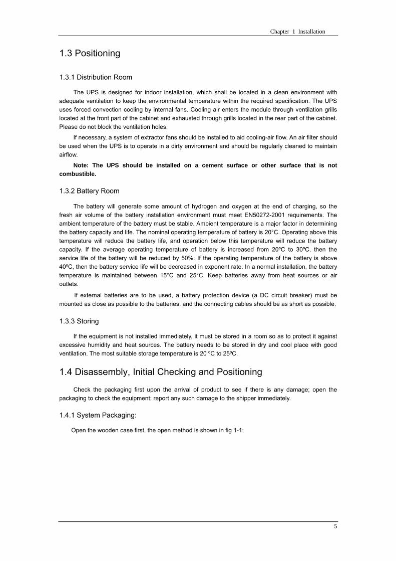
Chapter 1 Installation
5
13 Positioning
131 Distribution Room
The UPS is designed for indoor installation which shall be located in a clean environment with
adequate ventilation to keep the environmental temperature within the required specification The UPS
uses forced convection cooling by internal fans Cooling air enters the module through ventilation grills
located at the front part of the cabinet and exhausted through grills located in the rear part of the cabinet
Please do not block the ventilation holes
If necessary a system of extractor fans should be installed to aid cooling-air flow An air filter should
be used when the UPS is to operate in a dirty environment and should be regularly cleaned to maintain
airflow
Note The UPS should be installed on a cement surface or other surface that is not
combustible
132 Battery Room
The battery will generate some amount of hydrogen and oxygen at the end of charging so the
fresh air volume of the battery installation environment must meet EN50272-2001 requirements The
ambient temperature of the battery must be stable Ambient temperature is a major factor in determining
the battery capacity and life The nominal operating temperature of battery is 20degC Operating above this
temperature will reduce the battery life and operation below this temperature will reduce the battery
capacity If the average operating temperature of battery is increased from 20ordmC to 30ordmC then the
service life of the battery will be reduced by 50 If the operating temperature of the battery is above
40ordmC then the battery service life will be decreased in exponent rate In a normal installation the battery
temperature is maintained between 15degC and 25degC Keep batteries away from heat sources or air
outlets
If external batteries are to be used a battery protection device (a DC circuit breaker) must be
mounted as close as possible to the batteries and the connecting cables should be as short as possible
133 Storing
If the equipment is not installed immediately it must be stored in a room so as to protect it against
excessive humidity and heat sources The battery needs to be stored in dry and cool place with good
ventilation The most suitable storage temperature is 20 ordmC to 25ordmC
14 Disassembly Initial Checking and Positioning
Check the packaging first upon the arrival of product to see if there is any damage open the
packaging to check the equipment report any such damage to the shipper immediately
141 System Packaging
Open the wooden case first the open method is shown in fig 1-1
Chapter 1 Installation
6
Fig 1-1 Open method
Firstly open the top plate of the steel-edged wooden case with slotted awl and plier followed by
sideboards Be careful not to scratch the product See fig 1-2
Fig 1-2 Disassemble the case
Take out the foam after disassembling the sideboards of the case as shown in fig 1-3
Chapter 1 Installation
7
Fig 1-3 Complete the disassembly
Tip Dismantle the bolt that connects the cabinet and wooden pallet after disassembly then lift the
cabinet to installation position The dismantlement should be careful so as not to scratch the body
Verify the product label and confirm the correctness of the equipment The equipment label is
attached on the back of front door The UPS model capacity and main parameters are marked on the
label
142 Module Packaging
The open method is shown in fig 1-4
The packing case should be placed horizontal and stable
Fig 1-4 Open method
Cut the plastic packing belt and scotch tape to open the carton see fig 1-5
Chapter 1 Installation
8
Fig 1-5 Open the carton
Open the foamed cover the equipment with plastic package can be see as shown in fig 1-6
Fig 1-6 Open the foamed cover
At last take out the equipment with plastic package and dismantle the packaging materials
Warm Tips Please dispose the wasted materials in accordance with environmental
protection requirements after disassembly
To prolong the service life the place chosen for the UPS must guarantee
Easy wiring
Sufficient space for operation
CartonFoamed package
Carton
Equipment
Top cover of foamed package
Foamed package
Chapter 1 Installation
9
Air sufficient enough to dispel heat produced by UPS
Against ambient corrosive gases
Against excessive humidity and heat sources
Against dust
With the current fire prevention requirements
The operating environment temperature is within 20~25 The batteries are at maximum
efficiency in this temperature range (for information about the battery storage and transportation as
well as the environment please refer to table 6-2)
143 UPS Composition
UPS composition shall refer to fig 1-7 UPS configuration shall refer to table 1-1
功率模块
旁路模块
开关单元 配电单元
2m cabinet (front view) 2m cabinet (back view)
Bypass module
Power module
Distribution
unit
Switch unit
Chapter 1 Installation
10
开关单元
旁路模块
功率模块
配电单元
16m cabinet (front view) 16m cabinet (back view)
Fig 1-7 UPS Composition Diagram
Table 1-1 UPS Configuration Table
Involved part name Quantity (Piece) Note
Cabinet
Switch PDU 1 Standard configuration
Monitoring + bypass
module 1 Standard configuration
Power module Power module 1~6 or 1~10
Field installation is
required
144 Operation Space
As UPS has no ventilation grills at either sides no clearances are required for the sides
To enable routine tightening of power terminations within the cabinet it is recommended that
clearance around the front and back of the equipment should be sufficient to enable free passage of
personnel with the doors fully opened
145 Front and Back Access
The component layout of the UPS supports front and back access for servicing diagnosing and
repairing the UPS thus reducing the space requirement for side access
146 Final Positioning
When the equipment has been finally positioned ensure the adjustable feet are set so that the UPS
will remain stationary and stable
147 Power Module Installation
The installation position of power module and output distribution module are shown in fig 1-8 the
installation principle of these module is to installed from bottom to top to prevent inclination of the cabinet
due to high center of gravity
As is shown in fig 1-8 the installation procedure of power module is as follows
Switch unit
Bypass module
Power module
Distribution unit
Chapter 1 Installation
11
1 Each module shall be installed from bottom to top the default setting of the system is module No 1
2 3 4 5 6 7 8 9 and 10
2 Insert the module into installation position and push in the cabinet The wiring terminals in between
shall be tight and excessive force shall be prevented against the damage to inserted pins of the
terminals
3 Fix the module to the cabinet though the mounting holes on two sides of the front plate of the
module
固定孔
A处放大
Fig 1-8 Power Module Installation Diagram
148 Cable Entry
Cables can enter the UPS from top and below as shown in fig 1-9 Both the top and bottom of the
UPS have cable entrance
The recommended installation practice is to install power cables in the entrance channel
at both sides of the cabinet back door so as not to affect the ventilation
进线通道 进线通道
Fig 1-9 Cable Entry Diagram
Power module
Fixing hole
Amplification of A
Cable entrance Cable entrance
Chapter 1 Installation
12
15 Protective Devices
For safety concerns it is recommended to install external circuit breakers or other protective devices
for the input AC supply of the UPS system This section provides generic practical information for
qualified installation engineers The installation engineers should have the knowledge of the regulatory
wiring standards and of the equipment to be installed
151 Rectifier and Bypass Input Supply of the UPS
Install suitable protective devices in the distribution unit of the incoming mains supply considering
the power cable current-carrying capacity and overload capacity of the system (see Table 1)Generally
the magnetic circuit breaker with IEC60947-2 tripping curve C (normal) at the 125 of the current listed
in table 1-1 is recommended
Note
For IT power network system 4-pole protective device must be installed on the external input
distribution of the UPS
If protection against earth faults (RCD devices) is required for the upstream of the input supply the
installed device should
Sensitive to DC unidirectional pulses (class A) in the network
Insensitive to transient current pulses
Have an average sensitivity that is adjustable between 03A~1A
The RCCB must be sensitive to DC unidirectional pulses (class A) in the network while insensitive
to transient current pulses as shown in fig 1-10 respectively
Fig 1-10 RCCB sign
152 Battery
A battery unit is composed of 40 batteries connected in series a centreline is drawn from in
between (the joint part between the 20th and 21st battery) plus the line drawn from the front and back
there are altogether 3 lines connected with UPS line contact bank The battery line must push through a
DC circuit breaker before connecting to corresponding UPS line contact bank The detailed wiring please
refer to fig 1-11 below
Fig 1-11 Diagram of batteries connected in series
40 batteries connected in series
Chapter 1 Installation
13
153 UPS Output
A main output switch has been installed in UPS the user shall install the over current protective
device on the bypass of each output of the external distribution cabinet
16 Power Cables
Design the cables according to the descriptions in this section and local regulatory wiring standards
and the environmental conditions should be taken into consideration Refer to IEC60950-1 Table 3B
Warning
Prior to cabling the UPS confirm the status and positions of the switches of the UPS rectifier input
power supply bypass power supply and mains power distribution board
Ensure that these switches are opened and attached with WARNING label so as to prevent
unauthorized operation to these switches
161 Maximum stable state current and configuration of cable system please refer to
table 1-2
Table 1-2 Maximum stable state current and configuration of cable system
System Name MD-06010 MD-09015 MD-12020 MD-10010 MD-15015 MD-20020
Capacity
System
capacity 60kVA 90kVA 120kVA 100kVA 150kVA 200kVA
Module
capacity 10kVA 15kVA 20kVA 10kVA 15kVA 20kVA
Cabinet
dimension 6009001600(WDH mm) 6009002000(WDH mm)
Main
Input
Rated
current A 90 136 180 150 227 300
Cable mm2 25 35 50 50 75 75
Output
Rated
current A 90 136 180 150 227 300
Cable mm2 25 35 50 50 75 75
Battery
Rated
current A 106 160 212 178 265 355
Cable mm2 35 50 75 50 75 90
PE Cable mm2 35 50 75 50 75 90
Warning
FAILURE TO FOLLOW ADEQUATE EARTHING PROCEDURES CAN RESULT IN EMI ELECTRIC
SHOCK HAZARD OR RISK OF FIRE
Chapter 1 Installation
14
162 Cable Connection
Note
The operations described in this section must be performed by authorized electricians or qualified
technical personnel If you have any difficulties do not hesitate to contact our Customer Service amp
Support department at the address given at the beginning of this manual
After the equipment has been finally positioned and secured connect the power cables as
described in the following procedures
1 Verify that all the external input distribution switches of the UPS are completely opened and the
UPS internal maintenance bypass switch is opened Attach necessary warning signs to these
switches to prevent unauthorized operation
2 Open the back door of the cabinet remove the cover and then the input and output terminal
battery terminal and earth terminal are visible
3 Connect the input earth wire to input earth terminal Please note the earth wire shall be connected
in accordance with related local or state regulation
4 For common bypass and rectifier inputs connect the AC input supply cables to the UPS input
terminals (Main input A-B-C-N) and connect the output loaded cable to the UPS output terminals
(Output A-B-C-N) and tighten the connections to 13 Nm (M8 Bolt) ENSURE CORRECT PHASE
ROTATION
5 Connect the battery cables between the UPS battery terminals and battery switch ENSURE
CORRECT PHASE ROTATION
Warning-Hazardous battery terminal voltage of 400Vdc
Ensure the correct polarity connection between the battery terminals and the UPS terminals Positive
terminal to positive terminal negative terminal to negative terminal and disconnect one or more than
one cable between every two layers of batteries Do not connect the cables and close the battery
circuit breakers before getting the approval from the commissioning engineer
6 Re-install all the protective covers
17 Control and Communication Cabling
As shown in fig 1-12 the front panel of the bypass module will provide dry contact interface
(J2~J10) communication interface (RS232 485 and SNMP card interface) as well as LBS interface
干接点接口
SNMP卡接口
RS485接口
RS232接口LBS接口
Fig 1-12 Dry contact interface and communication interface
Dry contact
interface
SNMP card port
LBS port RS232 port
RS485 port
Chapter 1 Installation
15
The UPS accepts external signal from zero-voltage (dry) contacts connected through external dry
contact terminals produced and phoenix terminals that are in bypass module Through software
programming these signals become active when these contacts connect to +24V to ground)The cables
connected to DRY terminal must be separated from power cables Moreover these cables should be
double insulated with a typical 05 to 15 mm2
cross-section area for a maximum connection length
between 25 and 50 meters
171 Dry Contact Interface of Battery and Environmental Temperature Detection
The input dry contact J2 and J3 can detect the temperature of batteries and environment
respectively which can be used in environment monitoring and battery temperature compensation 1
J2 and J3 interfaces diagram are shown in fig 1-13 the description of interface is in table 1-3
Fig 1-13 Diagram of J2 and J3 dry contact for temperature detecting
Table 1-3 Description of input dry contact interface J2 and J3
Position Name Purpose
J21 TEMP_BAT Battery temperature detection
J22 GND Power ground
J31 TEMP_ENV Environment temperature detection
J32 GND Power ground
Note Specified temperature sensor is required for temperature detection (R25=5Ohm
B2550=3275) please confirm with the manufacturer or contact local maintenance engineers when
placing an order
172 Remote EPO Input Port
The UPS has an Emergency Power OFF (EPO) function This function can be activated by pressing
a button on the control panel of the UPS or through a remote contact provided by the user The EPO
pushbutton is protected by a hinged plastic cover
J4 is the input port for remote EPO It requires shorting NC and +24v during normal operation and
the EPO is triggered when opening NC and +24v or shorting NO and +24v The port diagram is shown in
fig 1-14 and port description is shown in table 1-4
Chapter 1 Installation
16
Fig 1-14 Diagram of input port for remote EPO
Table 1-4 Description of input port for remote EPO
Position Name Purpose
J41 EPO_NC EPO is activated when disconnecting fromJ42
J42 +12V +24V connect the common terminal of NC and NO
J43 +12V EPO is activated when shorting with J42
The EPO is triggered when shorting pin 2 and 3 or opening pin 2 and 1 of J4
If an external emergency stop facility is required it is connected via the reserved terminals of J4
The external emergency stop facility needs to use shielded cables to connect to the normally
openclosed remote stop switch between these two pins If this facility is not used then pin 3 and pin 4 of
J4 must be open or pin 1 and pin 2 of J4 must be shorted
Note
1 The emergency stop action within the UPS will shut down the rectifier inverter and static bypass
However it does not internally disconnect the mains input power supply To disconnect ALL power to
the UPS open the upstream input circuit breaker(s) when the EPO is activated
2 Pin 1 and 2 of J4 have been shorted before the UPS is delivered
173 Generator Input Dry Contact
J5 is status interface for generator connection Connect pin 2 of J5 with + 24 power supply it
indicates that the generator has been connected with the system The interface diagram is shown in fig
1-15 and interface description is shown in table 1-5
Chapter 1 Installation
17
Fig 1-15 Diagram of status interface and connection of generator
Table 1-5 Description of maintenance bypass switch and output switch status interface
Position Name Purpose
J51 +24V +24V power supply
J52 GEN Connection status of generator
J53 GND Power ground
174 BCB Input Port
J6 and J7 are the ports of BCB The port diagram is shown in fig 1-16 and description is shown in
table 1-6
BC
B_D
RV
BC
B_C
ON
T
J6 J7
BC
B_O
NL
+24V+24V
+24V
Fig 1-16 BCB Port
Table 1-6 Description of BCB port
Position Name Description
J61 BCB_DRV BCB actuating signal provide the actuating signal of +18V 20mA
J62 BCB_CONT BCB contact status connect with the normally open signal of BCB
J71 GND Power ground
J72 BCB_ONL BCB on-linendashinput (normally open) BCB is on-line when the signal
is connecting with GND
175 Battery Warning Output Dry Contact Interface
J8 is the output dry contact interface which outputs the battery warnings of low or excessive
voltage when the battery voltage is lower than set value an auxiliary dry contact signal will be
provided via the isolation of a relay The interface diagram is shown in fig 1-17 and description is
shown in table 1-7
Generator
Chapter 1 Installation
18
Fig 1-17 Battery warning dry contact interface diagram
Table 1-7 Battery warning dry contact interface description Position Name Purpose
J81 BAT_LOW_NC Battery warning relay (normally closed) will be open during warning
J82 BAT_LOW_NO Battery warning relay (normally open) will be closed during warning
J83 GND Center of battery warning relay
176 Integrated Warning Output Dry Contact Interface
J9 is the integrated warning output dry contact interface when one or more than one preset
warning is triggered the system will send an integrated warning information and provide an auxiliary
dry contact signal via the isolation of a relay The interface diagram is shown in fig 1-18 and description
is shown in table 1-8
Fig 1-18 Integrated warning dry contact interface diagram
Table 1-8 Integrated warning dry contact interface description Position Name Purpose
J91 ALARM_NC Integrated warning relay (normally closed) will be open during warning
J92 ALARM_NO Integrated warning relay (normally open) will be closed during warning
J93 GND Centre of integrated warning relay
177 Mains Failure Warning Output Dry Contact Interface
J10 is the output dry contact interface for mains failure warning when the mains fails the system
will send a mains failure warning information and provide an auxiliary dry contact signal via the isolation
of a relay The interface diagram is shown in fig 1-19 and description is shown in table 1-9
Chapter 1 Installation
19
Fig 1-19 Mains failure warning dry contact interface diagram
Table 1-9 Mains failure warning dry contact interface description Position Name Purpose
J91 UTI_FAIL_NC Mains failure warning relay(normally closed) will be open during
warning
J92 UTI_FAIL_NO Mains failure warning relay normally open) will be closed during
warning
J93 GND Centre of mains failure warning relay
178 RS232 Port and SNMP Card Port
RS232 and RS485 Port provide serial data which can be used for commissioning and maintenance
by authorized engineers or maintainers or can be used for networking or integrated monitoring system in
the service room
SNMP Card Port used for field installation of the communication option card(SNMP card)
179 LBS (Load Bus Synchronizer) Port
The dual bus system (DBS) consists of two independent UPS rack module systems as shown in fig
1-20 The dual bus system is configured for high availability and is suitable for powering the load with
dual inputs If the load is single-input load the static transfer switch and LBS control is recommended to
maintain both UPS outputs synchronized for uninterrupted transfers Please install the system according
to the installation descriptions for different system configurations
The dual bus system is supported by UPS it requires connecting the LBS signal cables of two UPS
when constructing the dual bus system please refer to relevant chapter for detailed configuration and
installation and the system software shall be configured as required
UPS 1
LBS
监控旁路模块 UPS 2
LBS
监控旁路模块
Fig 1-20 LBS Connection Diagram
18 Installation Drawing
Please refer to fig 1-21 fig 1-22 fig 1-23 and fig 1-24
UPS 1 monitoring bypass module
UPS 2 monitoring bypass module
Chapter 1 Installation
20
Fig 1-21 Installation Diagram
Chapter 1 Installation
21
顶视图
2m cabinet front view
16 m cabinet (front view)
Fig 1-22 UPS front view (Unit mm)
Top view
Chapter 1 Installation
22
A
2m cabinet
A
16m cabinet
Fig 1-23 UPS back view
Chapter 1 Installation
23
A
A处放大
Fig 1-24 UPS front view
Amplification of A
24 Chapter 2 Operations
24
Chapter 2 Operations
This chapter introduces the basic knowledge of UPS operations including working principle
operation mode battery management and protection
Warning Hazardous mains voltage andor battery voltage present(s)behind the protective cover
The components that can only be accessed by opening the protective cover with tools cannot be
operated by user
Only qualified service personnel are authorized to remove such covers
21 Introduction
UPS provides the critical load (such as communication and data processing equipment) with high
quality uninterruptible AC power The power from UPS is free from voltage and frequency variations and
disturbances (interruption and spike) experienced at the Mains AC input supply
This is achieved through high frequency double conversion power pulse width modulation (PWM)
associated with full digital signal processing control (DSP) which features high reliability and
convenience for use
211 Principle
As shown in fig 2-1 the AC input mains source is supplied at UPS input and converted into a DC
source This DC source feeds the Inverter that converts the DC source into a clean and input
independent AC source The battery powers the load through the inverter in case of an AC input mains
power failure The utility source can also power the load through the static bypass
When the UPS needs maintenance or repair the load can be transferred to maintenance bypass
without interruption and the power module and bypass module can be removed for maintenance
Chapter 2 Operations 25
25
Fig 2-1 System principle framework
212 Bypass Module
The circuit blocks labeled ldquobypass modulerdquo in fig 2-1 contain electronically controlled switching
circuits that enable the critical load to be connected to either the inverter output or to a bypass power
source via the static bypass line During normal system operation the load is connected to the inverter
but in the event of a UPS overload or inverter failure the load is automatically transferred to the static
bypass line
To provide a clean (no-break) load transfer between the inverter output and static bypass line the
inverter output and bypass supply must be fully synchronized during normal operating conditions This is
achieved through the inverter control electronics which makes the inverter frequency track that of the
static bypass supply provided that the bypass remains within an acceptable frequency window
A manually controlled maintenance bypass supply is incorporated into the UPS design It enables
the critical load to be powered from the utility (bypass) supply while the UPS is shut down for routine
maintenance
Note
When the UPS is operating in bypass mode or on maintenance bypass the connected equipment is
not protected from power failures or surges and sags
22 Operation Mode
The MD UPS is an on-line double-conversion reverse-transfer UPS that permits operation in these
modes
Normal mode
26 Chapter 2 Operations
26
Battery mode
Auto-Restart mode
Bypass mode
Maintenance mode (manual bypass)
ECO mode
Frequency converters mode
221 Normal Mode
The UPS inverter power modules continuously supplies the critical AC load The rectifiercharger
derives power from the AC mains input source and supplies DC power to the inverter while
simultaneously FLOAT or BOOST charging its associated backup battery
222 Battery Mode
Upon failure of the AC mains input power the inverter power modules which obtains power from the
battery supplies the critical AC load There is no interruption in power to the critical load upon failure
After restoration of the AC mains input power the ldquoNormal Moderdquo operation will continue automatically
without the necessity of user intervention
Note UPS can also be started through battery (charged) mode via battery cold start function upon
failure of the AC mains Therefore the battery power can be used independently to improve the
utilization rate of UPS
223 Auto-Restart Mode
The battery may become exhausted following an extended AC mains failure The inverter shuts
down when the battery reaches the End of Discharge voltage (EOD) The UPS may be programmed to
ldquoAuto Recovery after EODrdquo after a delay time if the AC mains recovers This mode and any delay time
are programmed by the commissioning engineer
During the process of delay time the battery will be charged by UPS to prevent any risks to load
equipment from future mains failure
224 Bypass Mode
If the inverter overload capacity is exceeded under normal mode or if the inverter becomes
unavailable for any reason the static transfer switch will perform a transfer of the load from the inverter
to the bypass source with no interruption in power to the critical AC load
225 Maintenance Mode
A manual bypass switch is available to ensure continuity of supply to the critical load when the UPS
becomes unavailable eg during a maintenance procedure
Note This manual bypass switch is fitted in all UPS modules Transfer UPS system to bypass
module for power supply first then close maintenance bypass switch Q2 followed by Q1 and Q3
Warning hazard may occur after transferring to maintenance bypass
After UPS being transferred to maintenance bypass power module and bypass module do not work
no display on LCD and input and output terminals as well as N bus are electrically connected
Chapter 2 Operations 27
27
226 ECO Mode
If economical (ECO) mode is selected the double-conversion UPS will stop to work so as to save
energy During the operation of ECO mode the load power will be supplied by bypass preferentially
When bypass power is within the range of normal frequency and voltage load power will be supplied by
bypass or the system will transfer to inverter input followed by load power interruption which extends
within 34 of the utility period Eg when the frequency is 50Hz the interruption time will be less than
15ms when the frequency is 60Hz the time will be less than 125ms
227 Frequency Converters Mode
If the frequency converter configuration is used by UPS it will provide 50Hz or 60Hz stable output
frequency The range of output frequency is 40Hz~70Hz Under this mode static bypass is unavailable
but battery can be selected according to the actual requirements of battery mode
23 Battery Management
231 Normal Function
The following functions should be fitted by commissioning engineers with specified software
1 Constant current boost charging
Current can be set up
2 Constant voltage boost charging
Voltage of boost charging can be set as required by the type of battery
For Valve Regulated Lead Acid (VRLA) batteries maximum boost charge voltage should not
exceed 24V cell
3 Float charge
Voltage of float charging can be set as required by the type of battery
For VRLA float charge voltage should be between 22V to 23V
4 Float charge temperature compensation (optional)
A coefficient of temperature compensation can be set as required by the type of battery
5 End of discharge (EOD) protection
If the battery voltage is lower than the EOD the battery converter will shut down and the battery is
isolated to avoid further battery discharge EOD is adjustable from 16V to 175V per cell (VRLA) or 09
to 11 V per cell
6 Battery low warning time
It is adjustable between 3 and 60 minutes The default is 5 minutes
232 Advanced Functions (Battery Self-checking and Maintenance)
At periodic intervals 20 of the rated capacity of the battery will be discharged automatically and
the actual load must exceed 20 of the rated UPS (KVA) capacity If the load is less than 20
auto-discharge cannot be executed The periodic interval can be set from 30 to 360 days The battery
self-test can be disabled
ConditionsmdashBattery at float charge for at least 5 hours load equal to 20~100 of rated UPS capacity
TriggermdashManually through the command of ldquoBattery Maintenance Testrdquo in LCD panel or automatically
Battery Self-Test Intervalmdash30-360 days (default setting is battery self-test disabled)
28 Chapter 2 Operations
28
24 Battery Protection
The following functions should be fitted by commissioning engineers with specified software
1 Battery Low Pre-warning
The battery under voltage pre-warning occurs before the end of discharge After this pre-warning
the battery should have the capacity for 3 remaining minutes discharging with full load The time is user
configured from 3 to 60 minutes
2 Battery discharge (EOD)off protection
If the battery voltage is lower than the EOD the battery converter will be shut down EOD is
adjustable from 16V to 175V per cell (VRLA) or 09 to 11 V per cell (NiCd)
3 Battery Circuit Breaker (BCB) Alarm
The alarm occurs when the battery disconnect device disconnects The external battery connects to
the UPS through the external battery circuit breaker The circuit breaker is manually closed and tripped
by the UPS control circuit
Chapter 3 Operation Instructions 29
29
Chapter 3 Operating Steps
This chapter describes UPS operation instructions in detail
All functional keys and LED display involved in operation instructions please refer to chapter 4
During operation the buzzer alarm may occur at any time Select ldquomuterdquo on LED to muffle the audible
alarm
Warning-Hazardous mains voltage andor battery voltage present(s)behind the protective cover
1 The components that can only be accessed by opening the protective cover with tools cannot be
operated by user
2 Only qualified service personnel are authorized to remove such covers
31 Power Switches
As shown in fig 3-1 open the front door of UPS the power switch is visible which includes input
switch output switch and maintenance bypass switch (with anti-misoperation stop plate)
输入开关 输出开关
维修旁路开关
Fig 3-1 Power switch location diagram
32 UPS Start-up
The UPS system only has a maintenance bypass isolating switch and all the other transfers are
processed automatically by internal control logics
Input switch Output switch
Maintenance bypass switch
30 Chapter 3 Operating Instructions
30
321 Normal Module Start
This procedure must be followed when turning on the UPS from a fully powered down condition
The operating procedures are as follows
Warning
This procedure results in mains voltage being applied to the UPS output terminals If any load
equipment is connected to the UPS output terminals please check with the load user that it is safe to
apply power If the load is not ready to receive power then ensure that it is safely to close the output
switch of external distribution cabinet
1 Close UPS output switch and input switch in turns
The LCD starts up at this time The Rectifier indicator flashes during the startup of rectifier The
rectifier enters normal operation state and after about 30s the rectifier indicator goes steady green After
initialization the bypass static switch closes The UPS Mimic LEDs will indicate as shown in table 3-1
Table 3-1 Indicator status
LED Status
Rectifier indicator Green
Battery indicator Red
Bypass indicator Green
Inverter indicator Off
Load indicator Green
Status indicator Green
Note
The output circuit breaker must be closed first followed by input circuit breaker or the rectifier cannot
be started and alarm ldquorectifier failurerdquo
The inverter starts up at this time the inverter indicator flashes After the rectifier enters normal
operation state UPS power supply will transfer from bypass to inverter then the bypass indicator turns
off and load indicator lights The status of indicators is shown in table 3-2
Table 3-2 Indicator Status
LED Status
Rectifier indicator Green
Battery indicator Red
Bypass indicator Off
Inverter indicator Green
Load indicator Green
Status indicator Green
Close external battery switch again battery indicator turns off a few minutes later the battery will be
charged by UPS which will enter normal mode operation The indicator status is shown in table 3-3
Table 3-3 Indicator status
LED Status
Rectifier indicator Green
Battery indicator Green
Bypass indicator Off
Inverter indicator Green
Load indicator Green
Status indicator Green
322 Operating steps of Battery cold Start
1 Check if the batteries have been connected close the external battery switch
Chapter 3 Operation Instructions 31
31
2 Press the red start-up button of battery under the rectifier input circuit breaker for 3 seconds (see fig
3-2)
The LCD starts up at this time The green battery indicator flashes The rectifier enters normal
operation states and after about 30s the battery indicator goes steady green
3 The inverter starts up automatically the green inverter indicator flashes The output of inverter
appears after 60s The UPS works on battery mode
32 Chapter 3 Operating Instructions
32
电池启动按钮
Fig 3-2 Position diagram of battery startup button
Battery startup button
Chapter 3 Operation Instructions 33
33
33 Procedure for Switching between Operation Modes
331 Procedure for Switching the UPS into Battery mode from Normal Mode
Open input switch to cut off the mains UPS enters the battery mode If UPS should be switched to
normal mode wait for a few seconds before close input switch so as to supply the mains again 10s
later the rectifier will start up automatically to supply power to the inverter
332 Procedure for Switching the UPS into Bypass mode from Normal Mode
Select ldquoTran Byprdquo on the LCD or press ldquooffrdquo buttons of each power module in turn
Note
In bypass mode the load is directly fed by the mains power instead of the pure AC power from the
inverter
333 Procedure for Switching the UPS into Normal from Bypass Mode
Select exit bypass mode on the LCD
334 Procedure for Switching the UPS into a Maintenance Bypass from Normal Mode
In normal operation this operation instruction will switch the load from inverter input to maintenance
bypass
Caution
Before making this operation read messages on display to be sure that bypass supply is regular and
the inverter is synchronous with it so as not to have a risk of a short interruption in powering the load
1 Press ldquoTran Byprdquo on the LCD or press ldquooffrdquo on each power module in turns
If press rdquoTran Byprdquo on the LCD the inverter indicator will flash green and the buzzer will alarm
If press ldquooffrdquo on each power module in turns the inverter indicator will go off and the buzzer will
alarm
The load will be transferred to static bypass and the inverter is closed
2 Close maintenance bypass switch Q2 the load power will be supplied by maintenance bypass and
then open the inverter circuit breaker Q1 output switch Q3 and battery switch
Warning
If you need to maintain the module wait for 10 minutes to let the DC bus capacitor fully discharge
before removing corresponding module
335 Procedure for Switching the UPS into Normal from a Maintenance Bypass Mode
This procedure can transfer the load to normal main mode when the UPS is operating under the
maintenance bypass mode
1 Close output switch Q3 and main switch Q1
The bypass indicator goes green and the load power will be supplied by bypass and maintenance
bypass
2 Open maintenance bypass switch Q2
34 Chapter 3 Operating Instructions
34
The load power is supplied by bypass In the meantime the rectifier starts up rectifier indicator goes
green 30s later at this time the inverter will start up automatically and transfer to inverter mode 1 min
later automatically
3 Close external battery switch the battery indicator goes off Check if the battery voltage on LCD
display is normal
34 Procedure for Completely Powering down a UPS
If you need to power down the UPS completely follow the procedures in section 334 to transfer the
UPS from normal mode to maintenance bypass mode
If you need to isolate the UPS from the AC power supply you should open the external input switch
35 EPO Procedure
The EPO button on UPS operator control and display panel is designed to switch off the UPS in
emergency conditions (eg fire flood etc)To achieve this just press the EPO button and the system
will turn off the rectifier inverter and stop powering the load immediately (including the inverter and
bypass output) and the battery stops charging or discharging
If the input utility is present the UPS control circuit will remain active however the output will be
turned off To completely isolate the UPS you need to open the external mains input supply to the UPS
rack
36 Language Selection
The LCD is available in two languages Chinese English and Korean
The language can be selected through LCD prompt window
37 Control Password
When the LCD displays ldquoinput control password 1rdquo the initial password is 12345678
Chapter 4 Operator Control and Display Panel 35
35
Chapter 4 Operator Control and Display Panel
This chapter introduces the functions and operation instructions of the parts on UPS operator control
and display panel in detail and provides LCD display information including LCD display types detailed
menu information prompt window information and UPS alarm list
41 Introduction
The operator control and display panel is located on the front panel of the UPS Through this LCD
panel the operator can operate and control the UPS and check all measured parameters UPS and
battery status and event and alarm logs The operator control panel is divided into three functional areas
as shown in fig 4-1 mimic current path LCD display amp Menu keys and Control and Operation Keys The
detailed description of parts on operator control and display panel is shown in table 4-1
Fig 4-1 UPS operator control and display panel
Table 4-1 Description of UPS operator control and display panel
Part No Function Button Function
REC Rectifier indicator EPO EPO switch
BAT Battery indicator TAB switch
BYP Bypass indicator ENTER confirm
INV Inverter indicator ESC exit
OUTPUT Load indicator
STATUS Status indicator
36 Chapter 4 Operator Control and Display Panel
36
411 LED Indicator
The LEDs shown on the mini current path represent the various UPS power paths and show the
current UPS operating status The status description of indicators is shown in table 4-2
Table 4-2 Status description of indicator
Indicator State Purpose
Rectifier
indicator
Steady green Rectifier normal for all modules
Flashing green Rectifier for at least on module normal mains normal
Steady red Rectifier fault
Flashing red Mains abnormal for at least one module
Off Rectifier not operating
Battery
indicator
Steady green Battery charging
Flashing green Battery discharging
Steady red
Battery abnormal (battery failure no battery or battery reverse) or
battery converter abnormal (failure over current or over temperature)
EOD
Flashing red Battery low voltage
Off Battery and battery converter normal battery not charging
Bypass
indicator
Steady green Load power supplied by bypass
Steady red Bypass power abnormal or out of normal range or static bypass
switch fault
Flashing red Bypass voltage abnormal
Off Bypass normal
Inverter
indicator
Steady green Load power supplied by inverter
Flashing green Inverter On start synchronization of standby (ECO mode) for at least
one module
Steady red System power not supplied by inverter inverter fault for at least one
module
Flashing red System power supplied by inverter inverter fault for at least one
module
Off Inverter not operating for all modules
Load
indicator
Steady green UPS output ON and normal
Steady red UPS output overload and overtime or output short or output no power
supply
Flashing red Overload output of UPS
Off No output of UPS
Status
indicator
Steady green Normal operation
Steady red Failure
412 Audible Alarm (buzzer)
There are two different types of audible alarm during UPS operation as shown in table 4-3
Table 4-3 description of audible alarm
Alarm Purpose
Two short alarm with
a long one
when system has general alarm (for example AC fault) this audible alarm
can be heard
Continuous alarm When system has serious faults (for example fuse or hardware fault) this
audible alarm can be heard
Chapter 4 Operator Control and Display Panel 37
37
413 Functional Keys
There are 4 functional keys on operator control and display panel which are used together with LCD
The functions description is shown in table 4-4
Table 4-4 Functions of functional keys
Functional key Functions
EPO switch To cut off the load power to shut down the rectifier inverter static
bypass and battery
TAB switch
ENTER confirm
ESC exit
42 LCD Display Type
Following the self-check of UPS LCD display the main LCD display is shown as fig 4-2 which can
be divided into three display windows system information data command and current record
Fig 4-2 Main LCD display
The description of LCD icon is shown in table 4-5
Table 4-5 Description of LCD icons
Icon Description
Bypass parameter
UPS system
information
window
Data
command
window
Current
record
window
38 Chapter 4 Operator Control and Display Panel
38
Icon Description
Main input parameter
History file system information
Function setting (display calibration password setting time setting date format
communication protocol and language setting) system setting (used by product
maintainers)
Battery data battery parameter setting (used by service staff)
Test (battery self-test battery maintenance)
Functional keys used by service staff (fault clearing history file clearing noise
clearing manual switch of bypass) userrsquos setting (system mode machine
number system ID output voltage adjustment frequency tracing speed
frequency tracing limit)
Output parameter
Load
Noise clearing noise clearing cancel
Log view page updown
Select a icon on LCD as shown in fig 4-3 to view the UPS parameter represented by this icon eg
select the LCD will display the data of system main input
Chapter 4 Operator Control and Display Panel 39
39
Fig 4-3 Select data
Or select and confirm a module as shown in fig 4-4 the LCD will display the
operating status of this module
Fig 4-4 Select a module
40 Chapter 4 Operator Control and Display Panel
40
Select in the operating status of a module to view the main input data of this module
Select in the operating status of a module to view the main output data of this module
Select in the operating status of a module to view the load data of this module
Select in the operating status of a module to view the maintenance code and module
software code of this module
Select to return to the previous page
Select to return to the home page
Default display
During the operation of system if therersquos no alarm in 2 min the system will display default After a
short delay the backlight of LCD display goes off press any key to reactivate the display
43 Detailed Description of Menu Items
The LCD main display shown in fig 4-2 is described in details below
UPS information window
UPS information window display the current time and UPS name The information of the window is
not necessary for the user to operate The information of this window is given in table 4-6
Table 4-6 Description of items in UPS system information window
Display contents Meaning
MD12020 UPS Name
1200 Current Time (format 24 hours hours minute)
UPS menu and data window
UPS menu window displays the menu name of data window while the data window displays the
related contents of selected menu in menu window Select UPS menu and data window to browse
related parameters of UPS and set related functions The details are given in table 4-7
Table 4-7 Item description of UPS menu and data window
Menu name Menu item Meaning
Main input
V phase(V) V phase
I phase(A) I phase
Freq(Hz) Input frequency
PF Power factor
Bypass input
V phase(V) V phase
Freq (Hz) Bypass frequency
I phase(A) I phase
PF Power factor
AC output
V phase(V) V phase
I phase(A) I phase
Freq (Hz) Output frequency
PF Power factor
This UPS Sout (kVA) Sout Apparent Power
Chapter 4 Operator Control and Display Panel 41
41
Menu name Menu item Meaning
modulersquos
load
Pout (kW) Pout Active Power
Qout (kVAR) Qout Reactive Power
Load () Load (The percentage of the UPS rating load)
Battery data
Environmental
Temp Environmental Temp
Battery
voltage(V) Battery bus voltage
Battery current
A) Battery bus current
Battery
Temp() Battery Temp
Remaining Time
(Min) Remaining battery backup time
Battery capacity
() The percentage compared with new battery capacity
battery
equalized
charging
Battery is equalized charging
battery float
charging Battery is float charging
Battery
disconnected Battery is not connected
Current
record (current alarm)
Display all current alarm The alarm list displayed on LCD of
UPS operator control and display panel please refer to table 4-9
History
record (history alarm)
Display all history alarm The alarm list displayed on LCD of
UPS operator control and display panel please refer to table 4-9
Menu
Language
(language
option) 2 languages can be selected
Settings
Display
calibration Adjust the accuracy of LCD display
Date format set MM DD YYYY and YYYY MM DD formats can be selected
Date amp Time DateTime set
Language set User can set the language (Chinese and English)
Communication
mode
Set communication mode MODBUS Power protocol and
company custom protocol modes can be selected Power
protocol mode can be divided into equipment address baud
rate set MODBUS protocol mode can be divided into
communication mode (RTUASCⅡ) equipment address
baud rate and check-bit set Company custom protocol mode
is the customed protocol of the company no option is
available
Control
password set User can modify control password 1
Test
Command
(Battery Test
Control
Battery
maintenance
test
This test will lead to the battery being partly discharged to
activate battery at the same time the approximate battery
capacity will be obtained Bypass must be in normal condition
the battery capacity should be above 25
42 Chapter 4 Operator Control and Display Panel
42
Menu name Menu item Meaning
Battery
self-check test
UPS switches to battery discharge for discharging to test if the
battery is normal Bypass must be in normal condition the
battery capacity should be above 25
Stop testing Manually Stop the test including maintenance test capacity test
UPS system
information
Monitoring
software version Provide monitoring software version
Rectified
software version Provide rectified software version
Inverted
software version Provide inverted software version
Serial No The serial no set when delivery from the factory
Rated
information Network setting of system operating
Module type Type of the module
44 Alarm List
The follow table 4-8 gives the complete list of all the UPS events displayed by history record window
and current record window
Table 4-8 Alarm List
Alarm Explanation
UPS power supply The system is in normal inverted power supply status
Bypass power
supply The system is in bypass power supply status
No power supply System no output
Battery equalized
charging Battery is in boost charging
Battery float
charging Battery is in float charging
Battery discharging The system is operating in battery discharging status
Battery connected Battery is connected
Battery
disconnected Battery is not connected
Maintenance circuit
breaker close Maintenance circuit breaker is close
Maintenance circuit
breaker open Maintenance circuit breaker is open
Emergency
shutdown System emergency shutdownEPO
Generator
connected External generator is connected
Mains abnormal Input mains abnormal
Bypass phase
conversion Bypass input phase converse
Bypass voltage
abnormal Bypass input voltage abnormal
Bypass fault Bypass fault
Bypass overload Bypass output is overload
Up to bypass
overtime of Bypass is overtime of overload
Chapter 4 Operator Control and Display Panel 43
43
Alarm Explanation
overload
Bypass frequency
tracing exceeds Bypass frequency is out of the tracing range
Switch times up to
in this hour
The times of switch between bypass and inverter exceeds 5 times in the latest
hour
Output short System output short
Battery EOD Battery voltage achieves shutdown point
Battery self-check The system enters battery self-check mode
Battery self-check
success Battery normal during system self-check
Battery manual
check failure Battery fault during system self-check
Battery
maintenance The system is in battery maintenance status
Battery
maintenance
success
Battery maintenance status completes
Battery
maintenance failure Battery maintenance process is not normal
Stop testing Battery self-check or battery maintenance status stops
Fault clearing Clear the alarmed fault
Delete history
record Delete all history record
N communication
node connected N module is connected to UPS system
N communication
node disconnected N module is not connected to UPS system
N rectifier fault N module rectifier fault
N inverter fault N module inverter fault
N rectifier
overheat N module rectifier overheat
N fan fault N module fan fault
N output overload N module output overload
N overtime of
overload N module output overtime of overload
N inverter
overheat N module inverter overheat
Inverter power
supply ban Inverter power ban supply
Manual switch of
bypass Switch the system to bypass output manually
Cancel manual
switch of bypass Switch the system from bypass to inverter output manually
Battery low voltage Battery low voltage
Battery reversal Battery polarity reversal
N inverter
protection N module inverter protection
Input N line
disconnected System input N line is not connected
Bypass fan fault Bypass module fan fault
N manual N module manual power off
44 Chapter 4 Operator Control and Display Panel
44
Alarm Explanation
shutdown
Chapter 5 Maintenance 45
45
Chapter 5 Installation of Parallel Operation System
The parallel operation system is installed as required by the installation procedures of the single
system and this chapter
The single devices are put parallel and connected as shown in fig 5-1 and the difference between
the lengths of the output cables of the single devices is not more than 10m It is recommended to use an
external bypass cabinet to facilitate maintenance and system testing
Fig 5-1 Typical 1+N parallel operation system
Note when the load exceeds is the capacity of the single device the maintenance bypass
switch CB3 must be removed
The cables for the parallel operation provide double insulation shielding up to 30m long the control
cables for the parallel operation must be connected with all single devices to form a closed loop as
shown in fig5-2
Other power supplies
Rectifier
Charger Inverter Inverter
Output power supply
Load connected
Mains power input L1 L2 L3 N terminal
Mains power inputL1 L2 L3 N terminal
Rectifier
Charger
46 Chapter 5 Maintenance
46
Fig5-2 parallel cables
Chapter 5 Maintenance 47
47
Chapter 6 Maintenance
This chapter introduces UPS maintenance including the maintenance instructions of power module
monitoring bypass module and the change method of dust filter
61 Instruction to Power Bypass and Output Power Distribution
Module
611 Precautions
1 Only maintaining engineers can maintain the power module and monitoring bypass module
2 In principle the power module and bypass module should be disassembled from top to bottom so
as to prevent any inclination from high gravity centre of the cabinet
3 To ensure the safety before maintaining power module and bypass module be sure to use a
multimeter to measure the DC bus capacitor voltage and ensure the voltage is below 60V before
operation and use a multimeter to measure the voltage between operating parts and the earth to
ensure the voltage is lower than hazardous voltage ie DC voltage is lower than 60Vdc and AC
maximum Voltage is lower than 424Vac
4 Bypass module doesnrsquot support any hot insertion and extraction only when UPS is in maintenance
bypass mode or UPS is completely power off can the bypass module be disassembled
5 The module can be maintained 10 mins after extracting power module and bypass module which
can be inserted into the cabinet 10 mins later
612 Instruction to Power Module
Suppose UPS were in normal mode and bypass were normal a module shall be maintained at
first
1 Press OFF of the module with a pin point or other tiny matter the module will shut down
automatically and exit the system
Note ensure if the remaining module will be overload when exiting a module If therersquos any risk of
overload transfer the whole UPS system to bypass followed by other operations
2 Take off the fixing bolt on the two sides of front and back plate of power module 10 mins later
extract the module from the cabinet
3 After maintaining the module push the module into the equipment cabinet (the interval between
two modules shall be more than 10s) fix the screw on the two sides Then the module will be
connected to UPS system automatically
613 Instruction to Bypass Module
Suppose UPS were in normal mode and the bypass were normal
1 Select LCD touch screen manual switch of bypass the UPS power will be supplied by bypass
2 Close maintenance bypass switch the UPS power will be supplied by maintenance bypass
3 Open UPS output switch and input switch
4 Open external battery switch
48 Chapter 5 Maintenance
48
5 Take off the fixing bolt at the two sides of front board of bypass module extract the front cable
assembly of the module and extract the module from the cabinet
6 After maintaining the module insert the module into the cabinet tighten the screw at the two sides
and connect the front cable assembly of manufacturerrsquos module
7 Close UPS output switch and input switch in turn
2 mins later bypass indicator on the operator control and display panel lights on which indicates
the normal power supply of bypass
8 Open maintenance bypass switch the inverter starts automatically 60s later the UPS will transfer
to normal mode
62 Replacing Dust Screen (optional)
As shown in fig 5-1 there are 3~4 dust filters on the back of UPSrsquo front door each screen is held in
place by a bracket on either side of each filter The procedure of replacing each filter is as follows
1 Open the UPSrsquo front door and locate the filters on the back side of the front door
2 Remove one bracket
3 Remove the dust screen to be replaced and insert the clean one
4 Reinstall the bracket
防尘网固定条
Fig 5-1 Dust screen on the back side of UPS front door
Bracket
Dust screen
Appendix 2 Toxic or Hazardous Materials or Elements Identification Table 49
49
Chapter 7 Product Specification
This chapter provides UPS product specification
71 Applicable Standards
The UPS has been designed to conform to the following European and international standards
Table 6-1 Compliance with European and International Standards
Item Normative reference
General safety requirements for UPS
used in operator access areas EN50091-1-1IEC62040-1-1AS 62040-1-1
Electromagnetic compatibility (EMC)
requirements for UPS EN50091-2IEC62040-2AS 62040-2(C3)
Method of specifying the performance
and test requirements of UPS EN50091-3IEC62040-3AS 62040-3(VFI SS 111)
Note The above mentioned product standards incorporate relevant compliance clauses with generic
IEC and EN standards for safety (IECENAS60950) electromagnetic emission and immunity
(IECEN AS61000 series) and construction (IECENAS60146 series and 60950)
72 Environmental Characteristics
Table 6-2 Environmental Properties
Items Unit Requirements
Acoustic noise level at 1
meter dB 550
Altitude of Operation m le1000m above sea level derate power by 1 per 100m
between 1000m and 2000m
Relative Humidity RH 0 to 95 non condensing
Operating Temperature 0 to 40 deg Battery life is halved for every 10degC increase
above 20degC
UPS Storage-Transport
Temperature -20~70
Recommended Battery
Storage Temperature -20~30 (20degC for optimum battery storage)
73 Mechanical Characteristics
Table 6-3 Mechanical Properties
Cabinet Specification Unit MD6010 MD9015
MD12020
MD10010 MD15015
MD20020
Mechanical Dimension
WtimesDtimesH mm 600times900times1600 600times900times2000
Weight kg 151 182
Color NA Black
Protection Level
IEC(60529) NA IP20
50 Chapter 5 Maintenance
50
Module type Unit MU10 MU15 MU20
Mechanical Dimension
WtimesDtimesH mm 440times590times134
Weight kg 21 22 22
Color NA Black
74 Electrical Characteristics (Input Rectifier)
Table 6-4 Rectifier AC input (mains)
Items Unit Parameter
Rated AC Input
Voltage Vac
380400415(three-phase and sharing neutral with the
bypass input)
Input voltage range Vac -40~+25
Frequency2 Hz 5060(range 40Hz~70Hz)
Power factor kWkVA full load 099
THD THDI 3
75 Electrical Characteristics (Intermediate DC Link)
Table 6-5 Battery
Items Unit Parameters
Battery bus
voltage Vdc Nominal plusmn240V one-side range 198V~288V
Quantity of
lead-acid cells Nominal 40=[1 battery(12V) ] 240=[1 battery(2V) ]
Float charge
voltage Vcell(VRLA)
225Vcell(selectable from 22Vcell~235Vcell)
Constant current and constant voltage charge mode
Temperature
compensation mVcl -30(selectable from 0~-50 25 or 30 or inhibit)
Ripple voltage V float le1
Ripple current C10 le5
equalized
charge voltage VRLA
24Vcell(selectable from 230Vcell~245Vcell)
Constant current and constant voltage charge mode
final
discharging
voltage
Vcell(VRLA)
165Vcell(selectable from 160Vcell ~ 1750Vcell) 06C
discharge current
175Vcell (selectable from 165Vcell ~ 18Vcell) 015C
discharge current
(EOD voltage changes linearly within the set range according to
discharge current)
Battery Charge Vcell 24Vcell(selectable from 23Vcell~245Vcell)
Constant current and constant voltage charge mode
Battery
Charging Power
Max Current
kW 10 UPS capacity (selectable from 0~20 UPS capacity)
Appendix 2 Toxic or Hazardous Materials or Elements Identification Table 51
51
76 Electrical Characteristics (Inverter Output)
Table 6-6 Inverter Output (to important load)
Rated
capacity(kVA) Unit 10~200
Rated AC voltage1 Vac 380400415(three-phase four-wire and sharing neutral with the
bypass)
Freqency2 Hz 5060
overload
110 load 1 hour
125 load 10min
150 load 1min
>150 load 200ms
Fault current 340 short current limitation for 200ms
Non linear load
capability 3 100
Neutral current
capability 170
Steady state
voltage stability
plusmn1(balanced load)
plusmn15(100 imbalance load)
Transient voltage
response 4 plusmn5
THD <15(linear load) <5(non linear load3)
Synchronization -
Window Rated frequency plusmn2Hz(selectable plusmn1~plusmn5Hz)
Max change rate of
synch frequency Hzs 1 selectable 01~5
Inverter voltage
range V(ac) plusmn5
Note
1 Factory setting is 380V Commissioning engineers can set to 400V or 415V
2 Factory setting is 50Hz Commissioning engineers can set to 60Hz
3 EN50091-3(1458) peak value factor is 3 1
4 IEC62040-3EN50091-3 including 0~100~0 load transient the recovery time is half
circle to within 5 of stable output voltage
52 Chapter 5 Maintenance
52
77 Electrical Characteristics(Bypass Mains Input)
Table 6-7 Bypass Mains Input
Rated
capacity(kVA) Unit 60 90 100 120 150 200
Rated AC
Voltage1 Vac
380400415
three-phase four-wire sharing neutral with the rectifier input and providing neutral
reference for the output
Rated current A
91380V
87400V
83415V
136380V
130400V
124415V
151380V
144400V
138415V
182380V
174400V
166415V
227380V
216400V
207415V
302380V
288400V
276415V
Overload
125 load long term
130 load 1 hour
150 load 6min
1000 load 100ms
Superior
protection
bypass line
NA Thermal-magnetic breaker the capacity is 125 of rated current output
IEC60947-2 curve C
Current rating
of neutral cable A 17timesIn
Frequency2 Hz 5060
Switch time
(between
bypass and
inverter)
ms Synchronized switch le1ms
Bypass voltage
tolerance Vac
Upper limit +10+15or+20 default +20
Lower limit -10 -20 -30 or-40 default-20
(acceptable stable bypass voltage delay 10s)
Bypass
frequency
tolerance
plusmn25 plusmn5 plusmn10 or plusmn20 default plusmn10
Synchronizatio
n-Window Hz Rated frequencyplusmn2Hz (selectable from plusmn05Hz~plusmn5Hz)
Note
1 Factory setting is 400V Commissioning engineers can set to 380V or 415V
2 Factory setting is 50Hz Commissioning engineers can set to 60Hz For example UPS is set to frequency
inverter mode and then bypass status will be neglected
78 Efficiency
Table 6-8 Efficiency Loss and Air Exchange
Rated Efficiency (kVA) Unit 10~200kVA
Normal mode(dual conversion) 95
ECO mode 99
Battery discharging efficiency (DCAC) (battery at nominal voltage 480Vdc and full-rated linear load)
battery mode 95
Appendix 2 Toxic or Hazardous Materials or Elements Identification Table 53
53
Appendix A A Guidebook to Ordering and Selection of MU System
MD series UPS module can be divided into equipment cabinet and power module For the cabinet
lectotype please refer to the description in fig 6-1
Fig 6-1 Cabinet Selection
For single power module type please refers to the description in fig 6-2
Fig 6-2 Power Module Selection
Egg the requirements of a plant room are given below
The maximum power supply of the plant room is 120kVA however it is expected to be expanded to
200kVA in 3-5 years Therefore a 200kVA cabinet and 6 20kVA power module can be purchased to
constitute an uninterrupted 120kVA power system which can be expanded to 200kVA on-line The order
symbol is
1 set MD20020
6 set MU20
Option list
MD-SNMP card remote network monitoring card
MD-1600 dust filter dust screen for 16m cabinet
MD-2000 dust filter dust screen for 2m cabinet
Represents the capacity of a single power module
10 represents 10kVA
15 represents 15kVA
20 represents 20kVA
represents a single power module
Represents UPS system capacitypower module
06010 represents 60kVA10kVA
09015 represents 90kVA15kVA
12020 represents 120kVA20kVA
15015 represents 150kVA15kVA
20020 represents 200kVA20kVA
MD represents UPS cabinet
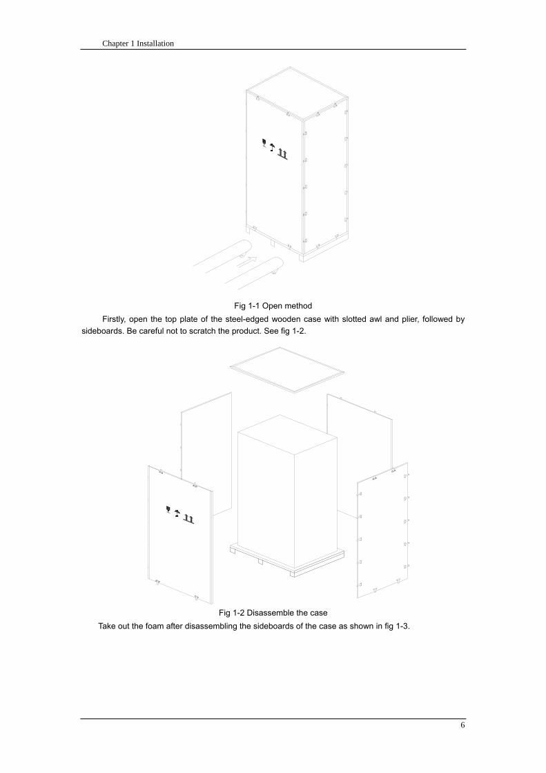
Chapter 1 Installation
6
Fig 1-1 Open method
Firstly open the top plate of the steel-edged wooden case with slotted awl and plier followed by
sideboards Be careful not to scratch the product See fig 1-2
Fig 1-2 Disassemble the case
Take out the foam after disassembling the sideboards of the case as shown in fig 1-3
Chapter 1 Installation
7
Fig 1-3 Complete the disassembly
Tip Dismantle the bolt that connects the cabinet and wooden pallet after disassembly then lift the
cabinet to installation position The dismantlement should be careful so as not to scratch the body
Verify the product label and confirm the correctness of the equipment The equipment label is
attached on the back of front door The UPS model capacity and main parameters are marked on the
label
142 Module Packaging
The open method is shown in fig 1-4
The packing case should be placed horizontal and stable
Fig 1-4 Open method
Cut the plastic packing belt and scotch tape to open the carton see fig 1-5
Chapter 1 Installation
8
Fig 1-5 Open the carton
Open the foamed cover the equipment with plastic package can be see as shown in fig 1-6
Fig 1-6 Open the foamed cover
At last take out the equipment with plastic package and dismantle the packaging materials
Warm Tips Please dispose the wasted materials in accordance with environmental
protection requirements after disassembly
To prolong the service life the place chosen for the UPS must guarantee
Easy wiring
Sufficient space for operation
CartonFoamed package
Carton
Equipment
Top cover of foamed package
Foamed package
Chapter 1 Installation
9
Air sufficient enough to dispel heat produced by UPS
Against ambient corrosive gases
Against excessive humidity and heat sources
Against dust
With the current fire prevention requirements
The operating environment temperature is within 20~25 The batteries are at maximum
efficiency in this temperature range (for information about the battery storage and transportation as
well as the environment please refer to table 6-2)
143 UPS Composition
UPS composition shall refer to fig 1-7 UPS configuration shall refer to table 1-1
功率模块
旁路模块
开关单元 配电单元
2m cabinet (front view) 2m cabinet (back view)
Bypass module
Power module
Distribution
unit
Switch unit
Chapter 1 Installation
10
开关单元
旁路模块
功率模块
配电单元
16m cabinet (front view) 16m cabinet (back view)
Fig 1-7 UPS Composition Diagram
Table 1-1 UPS Configuration Table
Involved part name Quantity (Piece) Note
Cabinet
Switch PDU 1 Standard configuration
Monitoring + bypass
module 1 Standard configuration
Power module Power module 1~6 or 1~10
Field installation is
required
144 Operation Space
As UPS has no ventilation grills at either sides no clearances are required for the sides
To enable routine tightening of power terminations within the cabinet it is recommended that
clearance around the front and back of the equipment should be sufficient to enable free passage of
personnel with the doors fully opened
145 Front and Back Access
The component layout of the UPS supports front and back access for servicing diagnosing and
repairing the UPS thus reducing the space requirement for side access
146 Final Positioning
When the equipment has been finally positioned ensure the adjustable feet are set so that the UPS
will remain stationary and stable
147 Power Module Installation
The installation position of power module and output distribution module are shown in fig 1-8 the
installation principle of these module is to installed from bottom to top to prevent inclination of the cabinet
due to high center of gravity
As is shown in fig 1-8 the installation procedure of power module is as follows
Switch unit
Bypass module
Power module
Distribution unit
Chapter 1 Installation
11
1 Each module shall be installed from bottom to top the default setting of the system is module No 1
2 3 4 5 6 7 8 9 and 10
2 Insert the module into installation position and push in the cabinet The wiring terminals in between
shall be tight and excessive force shall be prevented against the damage to inserted pins of the
terminals
3 Fix the module to the cabinet though the mounting holes on two sides of the front plate of the
module
固定孔
A处放大
Fig 1-8 Power Module Installation Diagram
148 Cable Entry
Cables can enter the UPS from top and below as shown in fig 1-9 Both the top and bottom of the
UPS have cable entrance
The recommended installation practice is to install power cables in the entrance channel
at both sides of the cabinet back door so as not to affect the ventilation
进线通道 进线通道
Fig 1-9 Cable Entry Diagram
Power module
Fixing hole
Amplification of A
Cable entrance Cable entrance
Chapter 1 Installation
12
15 Protective Devices
For safety concerns it is recommended to install external circuit breakers or other protective devices
for the input AC supply of the UPS system This section provides generic practical information for
qualified installation engineers The installation engineers should have the knowledge of the regulatory
wiring standards and of the equipment to be installed
151 Rectifier and Bypass Input Supply of the UPS
Install suitable protective devices in the distribution unit of the incoming mains supply considering
the power cable current-carrying capacity and overload capacity of the system (see Table 1)Generally
the magnetic circuit breaker with IEC60947-2 tripping curve C (normal) at the 125 of the current listed
in table 1-1 is recommended
Note
For IT power network system 4-pole protective device must be installed on the external input
distribution of the UPS
If protection against earth faults (RCD devices) is required for the upstream of the input supply the
installed device should
Sensitive to DC unidirectional pulses (class A) in the network
Insensitive to transient current pulses
Have an average sensitivity that is adjustable between 03A~1A
The RCCB must be sensitive to DC unidirectional pulses (class A) in the network while insensitive
to transient current pulses as shown in fig 1-10 respectively
Fig 1-10 RCCB sign
152 Battery
A battery unit is composed of 40 batteries connected in series a centreline is drawn from in
between (the joint part between the 20th and 21st battery) plus the line drawn from the front and back
there are altogether 3 lines connected with UPS line contact bank The battery line must push through a
DC circuit breaker before connecting to corresponding UPS line contact bank The detailed wiring please
refer to fig 1-11 below
Fig 1-11 Diagram of batteries connected in series
40 batteries connected in series
Chapter 1 Installation
13
153 UPS Output
A main output switch has been installed in UPS the user shall install the over current protective
device on the bypass of each output of the external distribution cabinet
16 Power Cables
Design the cables according to the descriptions in this section and local regulatory wiring standards
and the environmental conditions should be taken into consideration Refer to IEC60950-1 Table 3B
Warning
Prior to cabling the UPS confirm the status and positions of the switches of the UPS rectifier input
power supply bypass power supply and mains power distribution board
Ensure that these switches are opened and attached with WARNING label so as to prevent
unauthorized operation to these switches
161 Maximum stable state current and configuration of cable system please refer to
table 1-2
Table 1-2 Maximum stable state current and configuration of cable system
System Name MD-06010 MD-09015 MD-12020 MD-10010 MD-15015 MD-20020
Capacity
System
capacity 60kVA 90kVA 120kVA 100kVA 150kVA 200kVA
Module
capacity 10kVA 15kVA 20kVA 10kVA 15kVA 20kVA
Cabinet
dimension 6009001600(WDH mm) 6009002000(WDH mm)
Main
Input
Rated
current A 90 136 180 150 227 300
Cable mm2 25 35 50 50 75 75
Output
Rated
current A 90 136 180 150 227 300
Cable mm2 25 35 50 50 75 75
Battery
Rated
current A 106 160 212 178 265 355
Cable mm2 35 50 75 50 75 90
PE Cable mm2 35 50 75 50 75 90
Warning
FAILURE TO FOLLOW ADEQUATE EARTHING PROCEDURES CAN RESULT IN EMI ELECTRIC
SHOCK HAZARD OR RISK OF FIRE
Chapter 1 Installation
14
162 Cable Connection
Note
The operations described in this section must be performed by authorized electricians or qualified
technical personnel If you have any difficulties do not hesitate to contact our Customer Service amp
Support department at the address given at the beginning of this manual
After the equipment has been finally positioned and secured connect the power cables as
described in the following procedures
1 Verify that all the external input distribution switches of the UPS are completely opened and the
UPS internal maintenance bypass switch is opened Attach necessary warning signs to these
switches to prevent unauthorized operation
2 Open the back door of the cabinet remove the cover and then the input and output terminal
battery terminal and earth terminal are visible
3 Connect the input earth wire to input earth terminal Please note the earth wire shall be connected
in accordance with related local or state regulation
4 For common bypass and rectifier inputs connect the AC input supply cables to the UPS input
terminals (Main input A-B-C-N) and connect the output loaded cable to the UPS output terminals
(Output A-B-C-N) and tighten the connections to 13 Nm (M8 Bolt) ENSURE CORRECT PHASE
ROTATION
5 Connect the battery cables between the UPS battery terminals and battery switch ENSURE
CORRECT PHASE ROTATION
Warning-Hazardous battery terminal voltage of 400Vdc
Ensure the correct polarity connection between the battery terminals and the UPS terminals Positive
terminal to positive terminal negative terminal to negative terminal and disconnect one or more than
one cable between every two layers of batteries Do not connect the cables and close the battery
circuit breakers before getting the approval from the commissioning engineer
6 Re-install all the protective covers
17 Control and Communication Cabling
As shown in fig 1-12 the front panel of the bypass module will provide dry contact interface
(J2~J10) communication interface (RS232 485 and SNMP card interface) as well as LBS interface
干接点接口
SNMP卡接口
RS485接口
RS232接口LBS接口
Fig 1-12 Dry contact interface and communication interface
Dry contact
interface
SNMP card port
LBS port RS232 port
RS485 port
Chapter 1 Installation
15
The UPS accepts external signal from zero-voltage (dry) contacts connected through external dry
contact terminals produced and phoenix terminals that are in bypass module Through software
programming these signals become active when these contacts connect to +24V to ground)The cables
connected to DRY terminal must be separated from power cables Moreover these cables should be
double insulated with a typical 05 to 15 mm2
cross-section area for a maximum connection length
between 25 and 50 meters
171 Dry Contact Interface of Battery and Environmental Temperature Detection
The input dry contact J2 and J3 can detect the temperature of batteries and environment
respectively which can be used in environment monitoring and battery temperature compensation 1
J2 and J3 interfaces diagram are shown in fig 1-13 the description of interface is in table 1-3
Fig 1-13 Diagram of J2 and J3 dry contact for temperature detecting
Table 1-3 Description of input dry contact interface J2 and J3
Position Name Purpose
J21 TEMP_BAT Battery temperature detection
J22 GND Power ground
J31 TEMP_ENV Environment temperature detection
J32 GND Power ground
Note Specified temperature sensor is required for temperature detection (R25=5Ohm
B2550=3275) please confirm with the manufacturer or contact local maintenance engineers when
placing an order
172 Remote EPO Input Port
The UPS has an Emergency Power OFF (EPO) function This function can be activated by pressing
a button on the control panel of the UPS or through a remote contact provided by the user The EPO
pushbutton is protected by a hinged plastic cover
J4 is the input port for remote EPO It requires shorting NC and +24v during normal operation and
the EPO is triggered when opening NC and +24v or shorting NO and +24v The port diagram is shown in
fig 1-14 and port description is shown in table 1-4
Chapter 1 Installation
16
Fig 1-14 Diagram of input port for remote EPO
Table 1-4 Description of input port for remote EPO
Position Name Purpose
J41 EPO_NC EPO is activated when disconnecting fromJ42
J42 +12V +24V connect the common terminal of NC and NO
J43 +12V EPO is activated when shorting with J42
The EPO is triggered when shorting pin 2 and 3 or opening pin 2 and 1 of J4
If an external emergency stop facility is required it is connected via the reserved terminals of J4
The external emergency stop facility needs to use shielded cables to connect to the normally
openclosed remote stop switch between these two pins If this facility is not used then pin 3 and pin 4 of
J4 must be open or pin 1 and pin 2 of J4 must be shorted
Note
1 The emergency stop action within the UPS will shut down the rectifier inverter and static bypass
However it does not internally disconnect the mains input power supply To disconnect ALL power to
the UPS open the upstream input circuit breaker(s) when the EPO is activated
2 Pin 1 and 2 of J4 have been shorted before the UPS is delivered
173 Generator Input Dry Contact
J5 is status interface for generator connection Connect pin 2 of J5 with + 24 power supply it
indicates that the generator has been connected with the system The interface diagram is shown in fig
1-15 and interface description is shown in table 1-5
Chapter 1 Installation
17
Fig 1-15 Diagram of status interface and connection of generator
Table 1-5 Description of maintenance bypass switch and output switch status interface
Position Name Purpose
J51 +24V +24V power supply
J52 GEN Connection status of generator
J53 GND Power ground
174 BCB Input Port
J6 and J7 are the ports of BCB The port diagram is shown in fig 1-16 and description is shown in
table 1-6
BC
B_D
RV
BC
B_C
ON
T
J6 J7
BC
B_O
NL
+24V+24V
+24V
Fig 1-16 BCB Port
Table 1-6 Description of BCB port
Position Name Description
J61 BCB_DRV BCB actuating signal provide the actuating signal of +18V 20mA
J62 BCB_CONT BCB contact status connect with the normally open signal of BCB
J71 GND Power ground
J72 BCB_ONL BCB on-linendashinput (normally open) BCB is on-line when the signal
is connecting with GND
175 Battery Warning Output Dry Contact Interface
J8 is the output dry contact interface which outputs the battery warnings of low or excessive
voltage when the battery voltage is lower than set value an auxiliary dry contact signal will be
provided via the isolation of a relay The interface diagram is shown in fig 1-17 and description is
shown in table 1-7
Generator
Chapter 1 Installation
18
Fig 1-17 Battery warning dry contact interface diagram
Table 1-7 Battery warning dry contact interface description Position Name Purpose
J81 BAT_LOW_NC Battery warning relay (normally closed) will be open during warning
J82 BAT_LOW_NO Battery warning relay (normally open) will be closed during warning
J83 GND Center of battery warning relay
176 Integrated Warning Output Dry Contact Interface
J9 is the integrated warning output dry contact interface when one or more than one preset
warning is triggered the system will send an integrated warning information and provide an auxiliary
dry contact signal via the isolation of a relay The interface diagram is shown in fig 1-18 and description
is shown in table 1-8
Fig 1-18 Integrated warning dry contact interface diagram
Table 1-8 Integrated warning dry contact interface description Position Name Purpose
J91 ALARM_NC Integrated warning relay (normally closed) will be open during warning
J92 ALARM_NO Integrated warning relay (normally open) will be closed during warning
J93 GND Centre of integrated warning relay
177 Mains Failure Warning Output Dry Contact Interface
J10 is the output dry contact interface for mains failure warning when the mains fails the system
will send a mains failure warning information and provide an auxiliary dry contact signal via the isolation
of a relay The interface diagram is shown in fig 1-19 and description is shown in table 1-9
Chapter 1 Installation
19
Fig 1-19 Mains failure warning dry contact interface diagram
Table 1-9 Mains failure warning dry contact interface description Position Name Purpose
J91 UTI_FAIL_NC Mains failure warning relay(normally closed) will be open during
warning
J92 UTI_FAIL_NO Mains failure warning relay normally open) will be closed during
warning
J93 GND Centre of mains failure warning relay
178 RS232 Port and SNMP Card Port
RS232 and RS485 Port provide serial data which can be used for commissioning and maintenance
by authorized engineers or maintainers or can be used for networking or integrated monitoring system in
the service room
SNMP Card Port used for field installation of the communication option card(SNMP card)
179 LBS (Load Bus Synchronizer) Port
The dual bus system (DBS) consists of two independent UPS rack module systems as shown in fig
1-20 The dual bus system is configured for high availability and is suitable for powering the load with
dual inputs If the load is single-input load the static transfer switch and LBS control is recommended to
maintain both UPS outputs synchronized for uninterrupted transfers Please install the system according
to the installation descriptions for different system configurations
The dual bus system is supported by UPS it requires connecting the LBS signal cables of two UPS
when constructing the dual bus system please refer to relevant chapter for detailed configuration and
installation and the system software shall be configured as required
UPS 1
LBS
监控旁路模块 UPS 2
LBS
监控旁路模块
Fig 1-20 LBS Connection Diagram
18 Installation Drawing
Please refer to fig 1-21 fig 1-22 fig 1-23 and fig 1-24
UPS 1 monitoring bypass module
UPS 2 monitoring bypass module
Chapter 1 Installation
20
Fig 1-21 Installation Diagram
Chapter 1 Installation
21
顶视图
2m cabinet front view
16 m cabinet (front view)
Fig 1-22 UPS front view (Unit mm)
Top view
Chapter 1 Installation
22
A
2m cabinet
A
16m cabinet
Fig 1-23 UPS back view
Chapter 1 Installation
23
A
A处放大
Fig 1-24 UPS front view
Amplification of A
24 Chapter 2 Operations
24
Chapter 2 Operations
This chapter introduces the basic knowledge of UPS operations including working principle
operation mode battery management and protection
Warning Hazardous mains voltage andor battery voltage present(s)behind the protective cover
The components that can only be accessed by opening the protective cover with tools cannot be
operated by user
Only qualified service personnel are authorized to remove such covers
21 Introduction
UPS provides the critical load (such as communication and data processing equipment) with high
quality uninterruptible AC power The power from UPS is free from voltage and frequency variations and
disturbances (interruption and spike) experienced at the Mains AC input supply
This is achieved through high frequency double conversion power pulse width modulation (PWM)
associated with full digital signal processing control (DSP) which features high reliability and
convenience for use
211 Principle
As shown in fig 2-1 the AC input mains source is supplied at UPS input and converted into a DC
source This DC source feeds the Inverter that converts the DC source into a clean and input
independent AC source The battery powers the load through the inverter in case of an AC input mains
power failure The utility source can also power the load through the static bypass
When the UPS needs maintenance or repair the load can be transferred to maintenance bypass
without interruption and the power module and bypass module can be removed for maintenance
Chapter 2 Operations 25
25
Fig 2-1 System principle framework
212 Bypass Module
The circuit blocks labeled ldquobypass modulerdquo in fig 2-1 contain electronically controlled switching
circuits that enable the critical load to be connected to either the inverter output or to a bypass power
source via the static bypass line During normal system operation the load is connected to the inverter
but in the event of a UPS overload or inverter failure the load is automatically transferred to the static
bypass line
To provide a clean (no-break) load transfer between the inverter output and static bypass line the
inverter output and bypass supply must be fully synchronized during normal operating conditions This is
achieved through the inverter control electronics which makes the inverter frequency track that of the
static bypass supply provided that the bypass remains within an acceptable frequency window
A manually controlled maintenance bypass supply is incorporated into the UPS design It enables
the critical load to be powered from the utility (bypass) supply while the UPS is shut down for routine
maintenance
Note
When the UPS is operating in bypass mode or on maintenance bypass the connected equipment is
not protected from power failures or surges and sags
22 Operation Mode
The MD UPS is an on-line double-conversion reverse-transfer UPS that permits operation in these
modes
Normal mode
26 Chapter 2 Operations
26
Battery mode
Auto-Restart mode
Bypass mode
Maintenance mode (manual bypass)
ECO mode
Frequency converters mode
221 Normal Mode
The UPS inverter power modules continuously supplies the critical AC load The rectifiercharger
derives power from the AC mains input source and supplies DC power to the inverter while
simultaneously FLOAT or BOOST charging its associated backup battery
222 Battery Mode
Upon failure of the AC mains input power the inverter power modules which obtains power from the
battery supplies the critical AC load There is no interruption in power to the critical load upon failure
After restoration of the AC mains input power the ldquoNormal Moderdquo operation will continue automatically
without the necessity of user intervention
Note UPS can also be started through battery (charged) mode via battery cold start function upon
failure of the AC mains Therefore the battery power can be used independently to improve the
utilization rate of UPS
223 Auto-Restart Mode
The battery may become exhausted following an extended AC mains failure The inverter shuts
down when the battery reaches the End of Discharge voltage (EOD) The UPS may be programmed to
ldquoAuto Recovery after EODrdquo after a delay time if the AC mains recovers This mode and any delay time
are programmed by the commissioning engineer
During the process of delay time the battery will be charged by UPS to prevent any risks to load
equipment from future mains failure
224 Bypass Mode
If the inverter overload capacity is exceeded under normal mode or if the inverter becomes
unavailable for any reason the static transfer switch will perform a transfer of the load from the inverter
to the bypass source with no interruption in power to the critical AC load
225 Maintenance Mode
A manual bypass switch is available to ensure continuity of supply to the critical load when the UPS
becomes unavailable eg during a maintenance procedure
Note This manual bypass switch is fitted in all UPS modules Transfer UPS system to bypass
module for power supply first then close maintenance bypass switch Q2 followed by Q1 and Q3
Warning hazard may occur after transferring to maintenance bypass
After UPS being transferred to maintenance bypass power module and bypass module do not work
no display on LCD and input and output terminals as well as N bus are electrically connected
Chapter 2 Operations 27
27
226 ECO Mode
If economical (ECO) mode is selected the double-conversion UPS will stop to work so as to save
energy During the operation of ECO mode the load power will be supplied by bypass preferentially
When bypass power is within the range of normal frequency and voltage load power will be supplied by
bypass or the system will transfer to inverter input followed by load power interruption which extends
within 34 of the utility period Eg when the frequency is 50Hz the interruption time will be less than
15ms when the frequency is 60Hz the time will be less than 125ms
227 Frequency Converters Mode
If the frequency converter configuration is used by UPS it will provide 50Hz or 60Hz stable output
frequency The range of output frequency is 40Hz~70Hz Under this mode static bypass is unavailable
but battery can be selected according to the actual requirements of battery mode
23 Battery Management
231 Normal Function
The following functions should be fitted by commissioning engineers with specified software
1 Constant current boost charging
Current can be set up
2 Constant voltage boost charging
Voltage of boost charging can be set as required by the type of battery
For Valve Regulated Lead Acid (VRLA) batteries maximum boost charge voltage should not
exceed 24V cell
3 Float charge
Voltage of float charging can be set as required by the type of battery
For VRLA float charge voltage should be between 22V to 23V
4 Float charge temperature compensation (optional)
A coefficient of temperature compensation can be set as required by the type of battery
5 End of discharge (EOD) protection
If the battery voltage is lower than the EOD the battery converter will shut down and the battery is
isolated to avoid further battery discharge EOD is adjustable from 16V to 175V per cell (VRLA) or 09
to 11 V per cell
6 Battery low warning time
It is adjustable between 3 and 60 minutes The default is 5 minutes
232 Advanced Functions (Battery Self-checking and Maintenance)
At periodic intervals 20 of the rated capacity of the battery will be discharged automatically and
the actual load must exceed 20 of the rated UPS (KVA) capacity If the load is less than 20
auto-discharge cannot be executed The periodic interval can be set from 30 to 360 days The battery
self-test can be disabled
ConditionsmdashBattery at float charge for at least 5 hours load equal to 20~100 of rated UPS capacity
TriggermdashManually through the command of ldquoBattery Maintenance Testrdquo in LCD panel or automatically
Battery Self-Test Intervalmdash30-360 days (default setting is battery self-test disabled)
28 Chapter 2 Operations
28
24 Battery Protection
The following functions should be fitted by commissioning engineers with specified software
1 Battery Low Pre-warning
The battery under voltage pre-warning occurs before the end of discharge After this pre-warning
the battery should have the capacity for 3 remaining minutes discharging with full load The time is user
configured from 3 to 60 minutes
2 Battery discharge (EOD)off protection
If the battery voltage is lower than the EOD the battery converter will be shut down EOD is
adjustable from 16V to 175V per cell (VRLA) or 09 to 11 V per cell (NiCd)
3 Battery Circuit Breaker (BCB) Alarm
The alarm occurs when the battery disconnect device disconnects The external battery connects to
the UPS through the external battery circuit breaker The circuit breaker is manually closed and tripped
by the UPS control circuit
Chapter 3 Operation Instructions 29
29
Chapter 3 Operating Steps
This chapter describes UPS operation instructions in detail
All functional keys and LED display involved in operation instructions please refer to chapter 4
During operation the buzzer alarm may occur at any time Select ldquomuterdquo on LED to muffle the audible
alarm
Warning-Hazardous mains voltage andor battery voltage present(s)behind the protective cover
1 The components that can only be accessed by opening the protective cover with tools cannot be
operated by user
2 Only qualified service personnel are authorized to remove such covers
31 Power Switches
As shown in fig 3-1 open the front door of UPS the power switch is visible which includes input
switch output switch and maintenance bypass switch (with anti-misoperation stop plate)
输入开关 输出开关
维修旁路开关
Fig 3-1 Power switch location diagram
32 UPS Start-up
The UPS system only has a maintenance bypass isolating switch and all the other transfers are
processed automatically by internal control logics
Input switch Output switch
Maintenance bypass switch
30 Chapter 3 Operating Instructions
30
321 Normal Module Start
This procedure must be followed when turning on the UPS from a fully powered down condition
The operating procedures are as follows
Warning
This procedure results in mains voltage being applied to the UPS output terminals If any load
equipment is connected to the UPS output terminals please check with the load user that it is safe to
apply power If the load is not ready to receive power then ensure that it is safely to close the output
switch of external distribution cabinet
1 Close UPS output switch and input switch in turns
The LCD starts up at this time The Rectifier indicator flashes during the startup of rectifier The
rectifier enters normal operation state and after about 30s the rectifier indicator goes steady green After
initialization the bypass static switch closes The UPS Mimic LEDs will indicate as shown in table 3-1
Table 3-1 Indicator status
LED Status
Rectifier indicator Green
Battery indicator Red
Bypass indicator Green
Inverter indicator Off
Load indicator Green
Status indicator Green
Note
The output circuit breaker must be closed first followed by input circuit breaker or the rectifier cannot
be started and alarm ldquorectifier failurerdquo
The inverter starts up at this time the inverter indicator flashes After the rectifier enters normal
operation state UPS power supply will transfer from bypass to inverter then the bypass indicator turns
off and load indicator lights The status of indicators is shown in table 3-2
Table 3-2 Indicator Status
LED Status
Rectifier indicator Green
Battery indicator Red
Bypass indicator Off
Inverter indicator Green
Load indicator Green
Status indicator Green
Close external battery switch again battery indicator turns off a few minutes later the battery will be
charged by UPS which will enter normal mode operation The indicator status is shown in table 3-3
Table 3-3 Indicator status
LED Status
Rectifier indicator Green
Battery indicator Green
Bypass indicator Off
Inverter indicator Green
Load indicator Green
Status indicator Green
322 Operating steps of Battery cold Start
1 Check if the batteries have been connected close the external battery switch
Chapter 3 Operation Instructions 31
31
2 Press the red start-up button of battery under the rectifier input circuit breaker for 3 seconds (see fig
3-2)
The LCD starts up at this time The green battery indicator flashes The rectifier enters normal
operation states and after about 30s the battery indicator goes steady green
3 The inverter starts up automatically the green inverter indicator flashes The output of inverter
appears after 60s The UPS works on battery mode
32 Chapter 3 Operating Instructions
32
电池启动按钮
Fig 3-2 Position diagram of battery startup button
Battery startup button
Chapter 3 Operation Instructions 33
33
33 Procedure for Switching between Operation Modes
331 Procedure for Switching the UPS into Battery mode from Normal Mode
Open input switch to cut off the mains UPS enters the battery mode If UPS should be switched to
normal mode wait for a few seconds before close input switch so as to supply the mains again 10s
later the rectifier will start up automatically to supply power to the inverter
332 Procedure for Switching the UPS into Bypass mode from Normal Mode
Select ldquoTran Byprdquo on the LCD or press ldquooffrdquo buttons of each power module in turn
Note
In bypass mode the load is directly fed by the mains power instead of the pure AC power from the
inverter
333 Procedure for Switching the UPS into Normal from Bypass Mode
Select exit bypass mode on the LCD
334 Procedure for Switching the UPS into a Maintenance Bypass from Normal Mode
In normal operation this operation instruction will switch the load from inverter input to maintenance
bypass
Caution
Before making this operation read messages on display to be sure that bypass supply is regular and
the inverter is synchronous with it so as not to have a risk of a short interruption in powering the load
1 Press ldquoTran Byprdquo on the LCD or press ldquooffrdquo on each power module in turns
If press rdquoTran Byprdquo on the LCD the inverter indicator will flash green and the buzzer will alarm
If press ldquooffrdquo on each power module in turns the inverter indicator will go off and the buzzer will
alarm
The load will be transferred to static bypass and the inverter is closed
2 Close maintenance bypass switch Q2 the load power will be supplied by maintenance bypass and
then open the inverter circuit breaker Q1 output switch Q3 and battery switch
Warning
If you need to maintain the module wait for 10 minutes to let the DC bus capacitor fully discharge
before removing corresponding module
335 Procedure for Switching the UPS into Normal from a Maintenance Bypass Mode
This procedure can transfer the load to normal main mode when the UPS is operating under the
maintenance bypass mode
1 Close output switch Q3 and main switch Q1
The bypass indicator goes green and the load power will be supplied by bypass and maintenance
bypass
2 Open maintenance bypass switch Q2
34 Chapter 3 Operating Instructions
34
The load power is supplied by bypass In the meantime the rectifier starts up rectifier indicator goes
green 30s later at this time the inverter will start up automatically and transfer to inverter mode 1 min
later automatically
3 Close external battery switch the battery indicator goes off Check if the battery voltage on LCD
display is normal
34 Procedure for Completely Powering down a UPS
If you need to power down the UPS completely follow the procedures in section 334 to transfer the
UPS from normal mode to maintenance bypass mode
If you need to isolate the UPS from the AC power supply you should open the external input switch
35 EPO Procedure
The EPO button on UPS operator control and display panel is designed to switch off the UPS in
emergency conditions (eg fire flood etc)To achieve this just press the EPO button and the system
will turn off the rectifier inverter and stop powering the load immediately (including the inverter and
bypass output) and the battery stops charging or discharging
If the input utility is present the UPS control circuit will remain active however the output will be
turned off To completely isolate the UPS you need to open the external mains input supply to the UPS
rack
36 Language Selection
The LCD is available in two languages Chinese English and Korean
The language can be selected through LCD prompt window
37 Control Password
When the LCD displays ldquoinput control password 1rdquo the initial password is 12345678
Chapter 4 Operator Control and Display Panel 35
35
Chapter 4 Operator Control and Display Panel
This chapter introduces the functions and operation instructions of the parts on UPS operator control
and display panel in detail and provides LCD display information including LCD display types detailed
menu information prompt window information and UPS alarm list
41 Introduction
The operator control and display panel is located on the front panel of the UPS Through this LCD
panel the operator can operate and control the UPS and check all measured parameters UPS and
battery status and event and alarm logs The operator control panel is divided into three functional areas
as shown in fig 4-1 mimic current path LCD display amp Menu keys and Control and Operation Keys The
detailed description of parts on operator control and display panel is shown in table 4-1
Fig 4-1 UPS operator control and display panel
Table 4-1 Description of UPS operator control and display panel
Part No Function Button Function
REC Rectifier indicator EPO EPO switch
BAT Battery indicator TAB switch
BYP Bypass indicator ENTER confirm
INV Inverter indicator ESC exit
OUTPUT Load indicator
STATUS Status indicator
36 Chapter 4 Operator Control and Display Panel
36
411 LED Indicator
The LEDs shown on the mini current path represent the various UPS power paths and show the
current UPS operating status The status description of indicators is shown in table 4-2
Table 4-2 Status description of indicator
Indicator State Purpose
Rectifier
indicator
Steady green Rectifier normal for all modules
Flashing green Rectifier for at least on module normal mains normal
Steady red Rectifier fault
Flashing red Mains abnormal for at least one module
Off Rectifier not operating
Battery
indicator
Steady green Battery charging
Flashing green Battery discharging
Steady red
Battery abnormal (battery failure no battery or battery reverse) or
battery converter abnormal (failure over current or over temperature)
EOD
Flashing red Battery low voltage
Off Battery and battery converter normal battery not charging
Bypass
indicator
Steady green Load power supplied by bypass
Steady red Bypass power abnormal or out of normal range or static bypass
switch fault
Flashing red Bypass voltage abnormal
Off Bypass normal
Inverter
indicator
Steady green Load power supplied by inverter
Flashing green Inverter On start synchronization of standby (ECO mode) for at least
one module
Steady red System power not supplied by inverter inverter fault for at least one
module
Flashing red System power supplied by inverter inverter fault for at least one
module
Off Inverter not operating for all modules
Load
indicator
Steady green UPS output ON and normal
Steady red UPS output overload and overtime or output short or output no power
supply
Flashing red Overload output of UPS
Off No output of UPS
Status
indicator
Steady green Normal operation
Steady red Failure
412 Audible Alarm (buzzer)
There are two different types of audible alarm during UPS operation as shown in table 4-3
Table 4-3 description of audible alarm
Alarm Purpose
Two short alarm with
a long one
when system has general alarm (for example AC fault) this audible alarm
can be heard
Continuous alarm When system has serious faults (for example fuse or hardware fault) this
audible alarm can be heard
Chapter 4 Operator Control and Display Panel 37
37
413 Functional Keys
There are 4 functional keys on operator control and display panel which are used together with LCD
The functions description is shown in table 4-4
Table 4-4 Functions of functional keys
Functional key Functions
EPO switch To cut off the load power to shut down the rectifier inverter static
bypass and battery
TAB switch
ENTER confirm
ESC exit
42 LCD Display Type
Following the self-check of UPS LCD display the main LCD display is shown as fig 4-2 which can
be divided into three display windows system information data command and current record
Fig 4-2 Main LCD display
The description of LCD icon is shown in table 4-5
Table 4-5 Description of LCD icons
Icon Description
Bypass parameter
UPS system
information
window
Data
command
window
Current
record
window
38 Chapter 4 Operator Control and Display Panel
38
Icon Description
Main input parameter
History file system information
Function setting (display calibration password setting time setting date format
communication protocol and language setting) system setting (used by product
maintainers)
Battery data battery parameter setting (used by service staff)
Test (battery self-test battery maintenance)
Functional keys used by service staff (fault clearing history file clearing noise
clearing manual switch of bypass) userrsquos setting (system mode machine
number system ID output voltage adjustment frequency tracing speed
frequency tracing limit)
Output parameter
Load
Noise clearing noise clearing cancel
Log view page updown
Select a icon on LCD as shown in fig 4-3 to view the UPS parameter represented by this icon eg
select the LCD will display the data of system main input
Chapter 4 Operator Control and Display Panel 39
39
Fig 4-3 Select data
Or select and confirm a module as shown in fig 4-4 the LCD will display the
operating status of this module
Fig 4-4 Select a module
40 Chapter 4 Operator Control and Display Panel
40
Select in the operating status of a module to view the main input data of this module
Select in the operating status of a module to view the main output data of this module
Select in the operating status of a module to view the load data of this module
Select in the operating status of a module to view the maintenance code and module
software code of this module
Select to return to the previous page
Select to return to the home page
Default display
During the operation of system if therersquos no alarm in 2 min the system will display default After a
short delay the backlight of LCD display goes off press any key to reactivate the display
43 Detailed Description of Menu Items
The LCD main display shown in fig 4-2 is described in details below
UPS information window
UPS information window display the current time and UPS name The information of the window is
not necessary for the user to operate The information of this window is given in table 4-6
Table 4-6 Description of items in UPS system information window
Display contents Meaning
MD12020 UPS Name
1200 Current Time (format 24 hours hours minute)
UPS menu and data window
UPS menu window displays the menu name of data window while the data window displays the
related contents of selected menu in menu window Select UPS menu and data window to browse
related parameters of UPS and set related functions The details are given in table 4-7
Table 4-7 Item description of UPS menu and data window
Menu name Menu item Meaning
Main input
V phase(V) V phase
I phase(A) I phase
Freq(Hz) Input frequency
PF Power factor
Bypass input
V phase(V) V phase
Freq (Hz) Bypass frequency
I phase(A) I phase
PF Power factor
AC output
V phase(V) V phase
I phase(A) I phase
Freq (Hz) Output frequency
PF Power factor
This UPS Sout (kVA) Sout Apparent Power
Chapter 4 Operator Control and Display Panel 41
41
Menu name Menu item Meaning
modulersquos
load
Pout (kW) Pout Active Power
Qout (kVAR) Qout Reactive Power
Load () Load (The percentage of the UPS rating load)
Battery data
Environmental
Temp Environmental Temp
Battery
voltage(V) Battery bus voltage
Battery current
A) Battery bus current
Battery
Temp() Battery Temp
Remaining Time
(Min) Remaining battery backup time
Battery capacity
() The percentage compared with new battery capacity
battery
equalized
charging
Battery is equalized charging
battery float
charging Battery is float charging
Battery
disconnected Battery is not connected
Current
record (current alarm)
Display all current alarm The alarm list displayed on LCD of
UPS operator control and display panel please refer to table 4-9
History
record (history alarm)
Display all history alarm The alarm list displayed on LCD of
UPS operator control and display panel please refer to table 4-9
Menu
Language
(language
option) 2 languages can be selected
Settings
Display
calibration Adjust the accuracy of LCD display
Date format set MM DD YYYY and YYYY MM DD formats can be selected
Date amp Time DateTime set
Language set User can set the language (Chinese and English)
Communication
mode
Set communication mode MODBUS Power protocol and
company custom protocol modes can be selected Power
protocol mode can be divided into equipment address baud
rate set MODBUS protocol mode can be divided into
communication mode (RTUASCⅡ) equipment address
baud rate and check-bit set Company custom protocol mode
is the customed protocol of the company no option is
available
Control
password set User can modify control password 1
Test
Command
(Battery Test
Control
Battery
maintenance
test
This test will lead to the battery being partly discharged to
activate battery at the same time the approximate battery
capacity will be obtained Bypass must be in normal condition
the battery capacity should be above 25
42 Chapter 4 Operator Control and Display Panel
42
Menu name Menu item Meaning
Battery
self-check test
UPS switches to battery discharge for discharging to test if the
battery is normal Bypass must be in normal condition the
battery capacity should be above 25
Stop testing Manually Stop the test including maintenance test capacity test
UPS system
information
Monitoring
software version Provide monitoring software version
Rectified
software version Provide rectified software version
Inverted
software version Provide inverted software version
Serial No The serial no set when delivery from the factory
Rated
information Network setting of system operating
Module type Type of the module
44 Alarm List
The follow table 4-8 gives the complete list of all the UPS events displayed by history record window
and current record window
Table 4-8 Alarm List
Alarm Explanation
UPS power supply The system is in normal inverted power supply status
Bypass power
supply The system is in bypass power supply status
No power supply System no output
Battery equalized
charging Battery is in boost charging
Battery float
charging Battery is in float charging
Battery discharging The system is operating in battery discharging status
Battery connected Battery is connected
Battery
disconnected Battery is not connected
Maintenance circuit
breaker close Maintenance circuit breaker is close
Maintenance circuit
breaker open Maintenance circuit breaker is open
Emergency
shutdown System emergency shutdownEPO
Generator
connected External generator is connected
Mains abnormal Input mains abnormal
Bypass phase
conversion Bypass input phase converse
Bypass voltage
abnormal Bypass input voltage abnormal
Bypass fault Bypass fault
Bypass overload Bypass output is overload
Up to bypass
overtime of Bypass is overtime of overload
Chapter 4 Operator Control and Display Panel 43
43
Alarm Explanation
overload
Bypass frequency
tracing exceeds Bypass frequency is out of the tracing range
Switch times up to
in this hour
The times of switch between bypass and inverter exceeds 5 times in the latest
hour
Output short System output short
Battery EOD Battery voltage achieves shutdown point
Battery self-check The system enters battery self-check mode
Battery self-check
success Battery normal during system self-check
Battery manual
check failure Battery fault during system self-check
Battery
maintenance The system is in battery maintenance status
Battery
maintenance
success
Battery maintenance status completes
Battery
maintenance failure Battery maintenance process is not normal
Stop testing Battery self-check or battery maintenance status stops
Fault clearing Clear the alarmed fault
Delete history
record Delete all history record
N communication
node connected N module is connected to UPS system
N communication
node disconnected N module is not connected to UPS system
N rectifier fault N module rectifier fault
N inverter fault N module inverter fault
N rectifier
overheat N module rectifier overheat
N fan fault N module fan fault
N output overload N module output overload
N overtime of
overload N module output overtime of overload
N inverter
overheat N module inverter overheat
Inverter power
supply ban Inverter power ban supply
Manual switch of
bypass Switch the system to bypass output manually
Cancel manual
switch of bypass Switch the system from bypass to inverter output manually
Battery low voltage Battery low voltage
Battery reversal Battery polarity reversal
N inverter
protection N module inverter protection
Input N line
disconnected System input N line is not connected
Bypass fan fault Bypass module fan fault
N manual N module manual power off
44 Chapter 4 Operator Control and Display Panel
44
Alarm Explanation
shutdown
Chapter 5 Maintenance 45
45
Chapter 5 Installation of Parallel Operation System
The parallel operation system is installed as required by the installation procedures of the single
system and this chapter
The single devices are put parallel and connected as shown in fig 5-1 and the difference between
the lengths of the output cables of the single devices is not more than 10m It is recommended to use an
external bypass cabinet to facilitate maintenance and system testing
Fig 5-1 Typical 1+N parallel operation system
Note when the load exceeds is the capacity of the single device the maintenance bypass
switch CB3 must be removed
The cables for the parallel operation provide double insulation shielding up to 30m long the control
cables for the parallel operation must be connected with all single devices to form a closed loop as
shown in fig5-2
Other power supplies
Rectifier
Charger Inverter Inverter
Output power supply
Load connected
Mains power input L1 L2 L3 N terminal
Mains power inputL1 L2 L3 N terminal
Rectifier
Charger
46 Chapter 5 Maintenance
46
Fig5-2 parallel cables
Chapter 5 Maintenance 47
47
Chapter 6 Maintenance
This chapter introduces UPS maintenance including the maintenance instructions of power module
monitoring bypass module and the change method of dust filter
61 Instruction to Power Bypass and Output Power Distribution
Module
611 Precautions
1 Only maintaining engineers can maintain the power module and monitoring bypass module
2 In principle the power module and bypass module should be disassembled from top to bottom so
as to prevent any inclination from high gravity centre of the cabinet
3 To ensure the safety before maintaining power module and bypass module be sure to use a
multimeter to measure the DC bus capacitor voltage and ensure the voltage is below 60V before
operation and use a multimeter to measure the voltage between operating parts and the earth to
ensure the voltage is lower than hazardous voltage ie DC voltage is lower than 60Vdc and AC
maximum Voltage is lower than 424Vac
4 Bypass module doesnrsquot support any hot insertion and extraction only when UPS is in maintenance
bypass mode or UPS is completely power off can the bypass module be disassembled
5 The module can be maintained 10 mins after extracting power module and bypass module which
can be inserted into the cabinet 10 mins later
612 Instruction to Power Module
Suppose UPS were in normal mode and bypass were normal a module shall be maintained at
first
1 Press OFF of the module with a pin point or other tiny matter the module will shut down
automatically and exit the system
Note ensure if the remaining module will be overload when exiting a module If therersquos any risk of
overload transfer the whole UPS system to bypass followed by other operations
2 Take off the fixing bolt on the two sides of front and back plate of power module 10 mins later
extract the module from the cabinet
3 After maintaining the module push the module into the equipment cabinet (the interval between
two modules shall be more than 10s) fix the screw on the two sides Then the module will be
connected to UPS system automatically
613 Instruction to Bypass Module
Suppose UPS were in normal mode and the bypass were normal
1 Select LCD touch screen manual switch of bypass the UPS power will be supplied by bypass
2 Close maintenance bypass switch the UPS power will be supplied by maintenance bypass
3 Open UPS output switch and input switch
4 Open external battery switch
48 Chapter 5 Maintenance
48
5 Take off the fixing bolt at the two sides of front board of bypass module extract the front cable
assembly of the module and extract the module from the cabinet
6 After maintaining the module insert the module into the cabinet tighten the screw at the two sides
and connect the front cable assembly of manufacturerrsquos module
7 Close UPS output switch and input switch in turn
2 mins later bypass indicator on the operator control and display panel lights on which indicates
the normal power supply of bypass
8 Open maintenance bypass switch the inverter starts automatically 60s later the UPS will transfer
to normal mode
62 Replacing Dust Screen (optional)
As shown in fig 5-1 there are 3~4 dust filters on the back of UPSrsquo front door each screen is held in
place by a bracket on either side of each filter The procedure of replacing each filter is as follows
1 Open the UPSrsquo front door and locate the filters on the back side of the front door
2 Remove one bracket
3 Remove the dust screen to be replaced and insert the clean one
4 Reinstall the bracket
防尘网固定条
Fig 5-1 Dust screen on the back side of UPS front door
Bracket
Dust screen
Appendix 2 Toxic or Hazardous Materials or Elements Identification Table 49
49
Chapter 7 Product Specification
This chapter provides UPS product specification
71 Applicable Standards
The UPS has been designed to conform to the following European and international standards
Table 6-1 Compliance with European and International Standards
Item Normative reference
General safety requirements for UPS
used in operator access areas EN50091-1-1IEC62040-1-1AS 62040-1-1
Electromagnetic compatibility (EMC)
requirements for UPS EN50091-2IEC62040-2AS 62040-2(C3)
Method of specifying the performance
and test requirements of UPS EN50091-3IEC62040-3AS 62040-3(VFI SS 111)
Note The above mentioned product standards incorporate relevant compliance clauses with generic
IEC and EN standards for safety (IECENAS60950) electromagnetic emission and immunity
(IECEN AS61000 series) and construction (IECENAS60146 series and 60950)
72 Environmental Characteristics
Table 6-2 Environmental Properties
Items Unit Requirements
Acoustic noise level at 1
meter dB 550
Altitude of Operation m le1000m above sea level derate power by 1 per 100m
between 1000m and 2000m
Relative Humidity RH 0 to 95 non condensing
Operating Temperature 0 to 40 deg Battery life is halved for every 10degC increase
above 20degC
UPS Storage-Transport
Temperature -20~70
Recommended Battery
Storage Temperature -20~30 (20degC for optimum battery storage)
73 Mechanical Characteristics
Table 6-3 Mechanical Properties
Cabinet Specification Unit MD6010 MD9015
MD12020
MD10010 MD15015
MD20020
Mechanical Dimension
WtimesDtimesH mm 600times900times1600 600times900times2000
Weight kg 151 182
Color NA Black
Protection Level
IEC(60529) NA IP20
50 Chapter 5 Maintenance
50
Module type Unit MU10 MU15 MU20
Mechanical Dimension
WtimesDtimesH mm 440times590times134
Weight kg 21 22 22
Color NA Black
74 Electrical Characteristics (Input Rectifier)
Table 6-4 Rectifier AC input (mains)
Items Unit Parameter
Rated AC Input
Voltage Vac
380400415(three-phase and sharing neutral with the
bypass input)
Input voltage range Vac -40~+25
Frequency2 Hz 5060(range 40Hz~70Hz)
Power factor kWkVA full load 099
THD THDI 3
75 Electrical Characteristics (Intermediate DC Link)
Table 6-5 Battery
Items Unit Parameters
Battery bus
voltage Vdc Nominal plusmn240V one-side range 198V~288V
Quantity of
lead-acid cells Nominal 40=[1 battery(12V) ] 240=[1 battery(2V) ]
Float charge
voltage Vcell(VRLA)
225Vcell(selectable from 22Vcell~235Vcell)
Constant current and constant voltage charge mode
Temperature
compensation mVcl -30(selectable from 0~-50 25 or 30 or inhibit)
Ripple voltage V float le1
Ripple current C10 le5
equalized
charge voltage VRLA
24Vcell(selectable from 230Vcell~245Vcell)
Constant current and constant voltage charge mode
final
discharging
voltage
Vcell(VRLA)
165Vcell(selectable from 160Vcell ~ 1750Vcell) 06C
discharge current
175Vcell (selectable from 165Vcell ~ 18Vcell) 015C
discharge current
(EOD voltage changes linearly within the set range according to
discharge current)
Battery Charge Vcell 24Vcell(selectable from 23Vcell~245Vcell)
Constant current and constant voltage charge mode
Battery
Charging Power
Max Current
kW 10 UPS capacity (selectable from 0~20 UPS capacity)
Appendix 2 Toxic or Hazardous Materials or Elements Identification Table 51
51
76 Electrical Characteristics (Inverter Output)
Table 6-6 Inverter Output (to important load)
Rated
capacity(kVA) Unit 10~200
Rated AC voltage1 Vac 380400415(three-phase four-wire and sharing neutral with the
bypass)
Freqency2 Hz 5060
overload
110 load 1 hour
125 load 10min
150 load 1min
>150 load 200ms
Fault current 340 short current limitation for 200ms
Non linear load
capability 3 100
Neutral current
capability 170
Steady state
voltage stability
plusmn1(balanced load)
plusmn15(100 imbalance load)
Transient voltage
response 4 plusmn5
THD <15(linear load) <5(non linear load3)
Synchronization -
Window Rated frequency plusmn2Hz(selectable plusmn1~plusmn5Hz)
Max change rate of
synch frequency Hzs 1 selectable 01~5
Inverter voltage
range V(ac) plusmn5
Note
1 Factory setting is 380V Commissioning engineers can set to 400V or 415V
2 Factory setting is 50Hz Commissioning engineers can set to 60Hz
3 EN50091-3(1458) peak value factor is 3 1
4 IEC62040-3EN50091-3 including 0~100~0 load transient the recovery time is half
circle to within 5 of stable output voltage
52 Chapter 5 Maintenance
52
77 Electrical Characteristics(Bypass Mains Input)
Table 6-7 Bypass Mains Input
Rated
capacity(kVA) Unit 60 90 100 120 150 200
Rated AC
Voltage1 Vac
380400415
three-phase four-wire sharing neutral with the rectifier input and providing neutral
reference for the output
Rated current A
91380V
87400V
83415V
136380V
130400V
124415V
151380V
144400V
138415V
182380V
174400V
166415V
227380V
216400V
207415V
302380V
288400V
276415V
Overload
125 load long term
130 load 1 hour
150 load 6min
1000 load 100ms
Superior
protection
bypass line
NA Thermal-magnetic breaker the capacity is 125 of rated current output
IEC60947-2 curve C
Current rating
of neutral cable A 17timesIn
Frequency2 Hz 5060
Switch time
(between
bypass and
inverter)
ms Synchronized switch le1ms
Bypass voltage
tolerance Vac
Upper limit +10+15or+20 default +20
Lower limit -10 -20 -30 or-40 default-20
(acceptable stable bypass voltage delay 10s)
Bypass
frequency
tolerance
plusmn25 plusmn5 plusmn10 or plusmn20 default plusmn10
Synchronizatio
n-Window Hz Rated frequencyplusmn2Hz (selectable from plusmn05Hz~plusmn5Hz)
Note
1 Factory setting is 400V Commissioning engineers can set to 380V or 415V
2 Factory setting is 50Hz Commissioning engineers can set to 60Hz For example UPS is set to frequency
inverter mode and then bypass status will be neglected
78 Efficiency
Table 6-8 Efficiency Loss and Air Exchange
Rated Efficiency (kVA) Unit 10~200kVA
Normal mode(dual conversion) 95
ECO mode 99
Battery discharging efficiency (DCAC) (battery at nominal voltage 480Vdc and full-rated linear load)
battery mode 95
Appendix 2 Toxic or Hazardous Materials or Elements Identification Table 53
53
Appendix A A Guidebook to Ordering and Selection of MU System
MD series UPS module can be divided into equipment cabinet and power module For the cabinet
lectotype please refer to the description in fig 6-1
Fig 6-1 Cabinet Selection
For single power module type please refers to the description in fig 6-2
Fig 6-2 Power Module Selection
Egg the requirements of a plant room are given below
The maximum power supply of the plant room is 120kVA however it is expected to be expanded to
200kVA in 3-5 years Therefore a 200kVA cabinet and 6 20kVA power module can be purchased to
constitute an uninterrupted 120kVA power system which can be expanded to 200kVA on-line The order
symbol is
1 set MD20020
6 set MU20
Option list
MD-SNMP card remote network monitoring card
MD-1600 dust filter dust screen for 16m cabinet
MD-2000 dust filter dust screen for 2m cabinet
Represents the capacity of a single power module
10 represents 10kVA
15 represents 15kVA
20 represents 20kVA
represents a single power module
Represents UPS system capacitypower module
06010 represents 60kVA10kVA
09015 represents 90kVA15kVA
12020 represents 120kVA20kVA
15015 represents 150kVA15kVA
20020 represents 200kVA20kVA
MD represents UPS cabinet
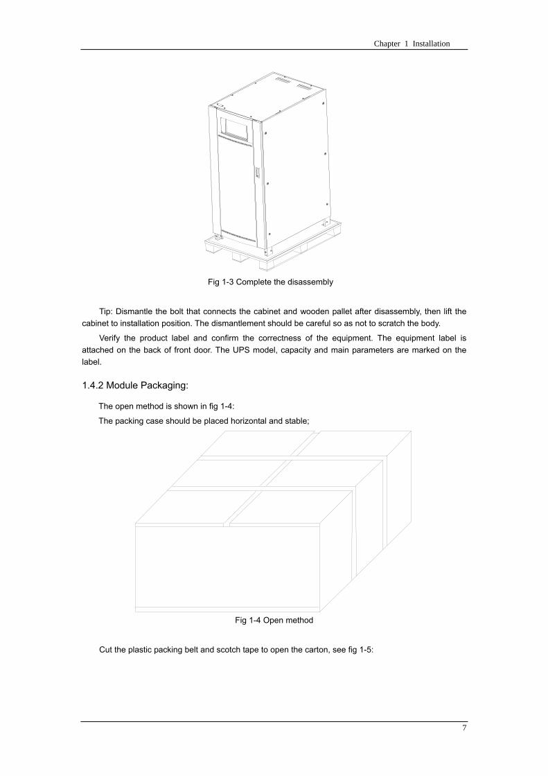
Chapter 1 Installation
7
Fig 1-3 Complete the disassembly
Tip Dismantle the bolt that connects the cabinet and wooden pallet after disassembly then lift the
cabinet to installation position The dismantlement should be careful so as not to scratch the body
Verify the product label and confirm the correctness of the equipment The equipment label is
attached on the back of front door The UPS model capacity and main parameters are marked on the
label
142 Module Packaging
The open method is shown in fig 1-4
The packing case should be placed horizontal and stable
Fig 1-4 Open method
Cut the plastic packing belt and scotch tape to open the carton see fig 1-5
Chapter 1 Installation
8
Fig 1-5 Open the carton
Open the foamed cover the equipment with plastic package can be see as shown in fig 1-6
Fig 1-6 Open the foamed cover
At last take out the equipment with plastic package and dismantle the packaging materials
Warm Tips Please dispose the wasted materials in accordance with environmental
protection requirements after disassembly
To prolong the service life the place chosen for the UPS must guarantee
Easy wiring
Sufficient space for operation
CartonFoamed package
Carton
Equipment
Top cover of foamed package
Foamed package
Chapter 1 Installation
9
Air sufficient enough to dispel heat produced by UPS
Against ambient corrosive gases
Against excessive humidity and heat sources
Against dust
With the current fire prevention requirements
The operating environment temperature is within 20~25 The batteries are at maximum
efficiency in this temperature range (for information about the battery storage and transportation as
well as the environment please refer to table 6-2)
143 UPS Composition
UPS composition shall refer to fig 1-7 UPS configuration shall refer to table 1-1
功率模块
旁路模块
开关单元 配电单元
2m cabinet (front view) 2m cabinet (back view)
Bypass module
Power module
Distribution
unit
Switch unit
Chapter 1 Installation
10
开关单元
旁路模块
功率模块
配电单元
16m cabinet (front view) 16m cabinet (back view)
Fig 1-7 UPS Composition Diagram
Table 1-1 UPS Configuration Table
Involved part name Quantity (Piece) Note
Cabinet
Switch PDU 1 Standard configuration
Monitoring + bypass
module 1 Standard configuration
Power module Power module 1~6 or 1~10
Field installation is
required
144 Operation Space
As UPS has no ventilation grills at either sides no clearances are required for the sides
To enable routine tightening of power terminations within the cabinet it is recommended that
clearance around the front and back of the equipment should be sufficient to enable free passage of
personnel with the doors fully opened
145 Front and Back Access
The component layout of the UPS supports front and back access for servicing diagnosing and
repairing the UPS thus reducing the space requirement for side access
146 Final Positioning
When the equipment has been finally positioned ensure the adjustable feet are set so that the UPS
will remain stationary and stable
147 Power Module Installation
The installation position of power module and output distribution module are shown in fig 1-8 the
installation principle of these module is to installed from bottom to top to prevent inclination of the cabinet
due to high center of gravity
As is shown in fig 1-8 the installation procedure of power module is as follows
Switch unit
Bypass module
Power module
Distribution unit
Chapter 1 Installation
11
1 Each module shall be installed from bottom to top the default setting of the system is module No 1
2 3 4 5 6 7 8 9 and 10
2 Insert the module into installation position and push in the cabinet The wiring terminals in between
shall be tight and excessive force shall be prevented against the damage to inserted pins of the
terminals
3 Fix the module to the cabinet though the mounting holes on two sides of the front plate of the
module
固定孔
A处放大
Fig 1-8 Power Module Installation Diagram
148 Cable Entry
Cables can enter the UPS from top and below as shown in fig 1-9 Both the top and bottom of the
UPS have cable entrance
The recommended installation practice is to install power cables in the entrance channel
at both sides of the cabinet back door so as not to affect the ventilation
进线通道 进线通道
Fig 1-9 Cable Entry Diagram
Power module
Fixing hole
Amplification of A
Cable entrance Cable entrance
Chapter 1 Installation
12
15 Protective Devices
For safety concerns it is recommended to install external circuit breakers or other protective devices
for the input AC supply of the UPS system This section provides generic practical information for
qualified installation engineers The installation engineers should have the knowledge of the regulatory
wiring standards and of the equipment to be installed
151 Rectifier and Bypass Input Supply of the UPS
Install suitable protective devices in the distribution unit of the incoming mains supply considering
the power cable current-carrying capacity and overload capacity of the system (see Table 1)Generally
the magnetic circuit breaker with IEC60947-2 tripping curve C (normal) at the 125 of the current listed
in table 1-1 is recommended
Note
For IT power network system 4-pole protective device must be installed on the external input
distribution of the UPS
If protection against earth faults (RCD devices) is required for the upstream of the input supply the
installed device should
Sensitive to DC unidirectional pulses (class A) in the network
Insensitive to transient current pulses
Have an average sensitivity that is adjustable between 03A~1A
The RCCB must be sensitive to DC unidirectional pulses (class A) in the network while insensitive
to transient current pulses as shown in fig 1-10 respectively
Fig 1-10 RCCB sign
152 Battery
A battery unit is composed of 40 batteries connected in series a centreline is drawn from in
between (the joint part between the 20th and 21st battery) plus the line drawn from the front and back
there are altogether 3 lines connected with UPS line contact bank The battery line must push through a
DC circuit breaker before connecting to corresponding UPS line contact bank The detailed wiring please
refer to fig 1-11 below
Fig 1-11 Diagram of batteries connected in series
40 batteries connected in series
Chapter 1 Installation
13
153 UPS Output
A main output switch has been installed in UPS the user shall install the over current protective
device on the bypass of each output of the external distribution cabinet
16 Power Cables
Design the cables according to the descriptions in this section and local regulatory wiring standards
and the environmental conditions should be taken into consideration Refer to IEC60950-1 Table 3B
Warning
Prior to cabling the UPS confirm the status and positions of the switches of the UPS rectifier input
power supply bypass power supply and mains power distribution board
Ensure that these switches are opened and attached with WARNING label so as to prevent
unauthorized operation to these switches
161 Maximum stable state current and configuration of cable system please refer to
table 1-2
Table 1-2 Maximum stable state current and configuration of cable system
System Name MD-06010 MD-09015 MD-12020 MD-10010 MD-15015 MD-20020
Capacity
System
capacity 60kVA 90kVA 120kVA 100kVA 150kVA 200kVA
Module
capacity 10kVA 15kVA 20kVA 10kVA 15kVA 20kVA
Cabinet
dimension 6009001600(WDH mm) 6009002000(WDH mm)
Main
Input
Rated
current A 90 136 180 150 227 300
Cable mm2 25 35 50 50 75 75
Output
Rated
current A 90 136 180 150 227 300
Cable mm2 25 35 50 50 75 75
Battery
Rated
current A 106 160 212 178 265 355
Cable mm2 35 50 75 50 75 90
PE Cable mm2 35 50 75 50 75 90
Warning
FAILURE TO FOLLOW ADEQUATE EARTHING PROCEDURES CAN RESULT IN EMI ELECTRIC
SHOCK HAZARD OR RISK OF FIRE
Chapter 1 Installation
14
162 Cable Connection
Note
The operations described in this section must be performed by authorized electricians or qualified
technical personnel If you have any difficulties do not hesitate to contact our Customer Service amp
Support department at the address given at the beginning of this manual
After the equipment has been finally positioned and secured connect the power cables as
described in the following procedures
1 Verify that all the external input distribution switches of the UPS are completely opened and the
UPS internal maintenance bypass switch is opened Attach necessary warning signs to these
switches to prevent unauthorized operation
2 Open the back door of the cabinet remove the cover and then the input and output terminal
battery terminal and earth terminal are visible
3 Connect the input earth wire to input earth terminal Please note the earth wire shall be connected
in accordance with related local or state regulation
4 For common bypass and rectifier inputs connect the AC input supply cables to the UPS input
terminals (Main input A-B-C-N) and connect the output loaded cable to the UPS output terminals
(Output A-B-C-N) and tighten the connections to 13 Nm (M8 Bolt) ENSURE CORRECT PHASE
ROTATION
5 Connect the battery cables between the UPS battery terminals and battery switch ENSURE
CORRECT PHASE ROTATION
Warning-Hazardous battery terminal voltage of 400Vdc
Ensure the correct polarity connection between the battery terminals and the UPS terminals Positive
terminal to positive terminal negative terminal to negative terminal and disconnect one or more than
one cable between every two layers of batteries Do not connect the cables and close the battery
circuit breakers before getting the approval from the commissioning engineer
6 Re-install all the protective covers
17 Control and Communication Cabling
As shown in fig 1-12 the front panel of the bypass module will provide dry contact interface
(J2~J10) communication interface (RS232 485 and SNMP card interface) as well as LBS interface
干接点接口
SNMP卡接口
RS485接口
RS232接口LBS接口
Fig 1-12 Dry contact interface and communication interface
Dry contact
interface
SNMP card port
LBS port RS232 port
RS485 port
Chapter 1 Installation
15
The UPS accepts external signal from zero-voltage (dry) contacts connected through external dry
contact terminals produced and phoenix terminals that are in bypass module Through software
programming these signals become active when these contacts connect to +24V to ground)The cables
connected to DRY terminal must be separated from power cables Moreover these cables should be
double insulated with a typical 05 to 15 mm2
cross-section area for a maximum connection length
between 25 and 50 meters
171 Dry Contact Interface of Battery and Environmental Temperature Detection
The input dry contact J2 and J3 can detect the temperature of batteries and environment
respectively which can be used in environment monitoring and battery temperature compensation 1
J2 and J3 interfaces diagram are shown in fig 1-13 the description of interface is in table 1-3
Fig 1-13 Diagram of J2 and J3 dry contact for temperature detecting
Table 1-3 Description of input dry contact interface J2 and J3
Position Name Purpose
J21 TEMP_BAT Battery temperature detection
J22 GND Power ground
J31 TEMP_ENV Environment temperature detection
J32 GND Power ground
Note Specified temperature sensor is required for temperature detection (R25=5Ohm
B2550=3275) please confirm with the manufacturer or contact local maintenance engineers when
placing an order
172 Remote EPO Input Port
The UPS has an Emergency Power OFF (EPO) function This function can be activated by pressing
a button on the control panel of the UPS or through a remote contact provided by the user The EPO
pushbutton is protected by a hinged plastic cover
J4 is the input port for remote EPO It requires shorting NC and +24v during normal operation and
the EPO is triggered when opening NC and +24v or shorting NO and +24v The port diagram is shown in
fig 1-14 and port description is shown in table 1-4
Chapter 1 Installation
16
Fig 1-14 Diagram of input port for remote EPO
Table 1-4 Description of input port for remote EPO
Position Name Purpose
J41 EPO_NC EPO is activated when disconnecting fromJ42
J42 +12V +24V connect the common terminal of NC and NO
J43 +12V EPO is activated when shorting with J42
The EPO is triggered when shorting pin 2 and 3 or opening pin 2 and 1 of J4
If an external emergency stop facility is required it is connected via the reserved terminals of J4
The external emergency stop facility needs to use shielded cables to connect to the normally
openclosed remote stop switch between these two pins If this facility is not used then pin 3 and pin 4 of
J4 must be open or pin 1 and pin 2 of J4 must be shorted
Note
1 The emergency stop action within the UPS will shut down the rectifier inverter and static bypass
However it does not internally disconnect the mains input power supply To disconnect ALL power to
the UPS open the upstream input circuit breaker(s) when the EPO is activated
2 Pin 1 and 2 of J4 have been shorted before the UPS is delivered
173 Generator Input Dry Contact
J5 is status interface for generator connection Connect pin 2 of J5 with + 24 power supply it
indicates that the generator has been connected with the system The interface diagram is shown in fig
1-15 and interface description is shown in table 1-5
Chapter 1 Installation
17
Fig 1-15 Diagram of status interface and connection of generator
Table 1-5 Description of maintenance bypass switch and output switch status interface
Position Name Purpose
J51 +24V +24V power supply
J52 GEN Connection status of generator
J53 GND Power ground
174 BCB Input Port
J6 and J7 are the ports of BCB The port diagram is shown in fig 1-16 and description is shown in
table 1-6
BC
B_D
RV
BC
B_C
ON
T
J6 J7
BC
B_O
NL
+24V+24V
+24V
Fig 1-16 BCB Port
Table 1-6 Description of BCB port
Position Name Description
J61 BCB_DRV BCB actuating signal provide the actuating signal of +18V 20mA
J62 BCB_CONT BCB contact status connect with the normally open signal of BCB
J71 GND Power ground
J72 BCB_ONL BCB on-linendashinput (normally open) BCB is on-line when the signal
is connecting with GND
175 Battery Warning Output Dry Contact Interface
J8 is the output dry contact interface which outputs the battery warnings of low or excessive
voltage when the battery voltage is lower than set value an auxiliary dry contact signal will be
provided via the isolation of a relay The interface diagram is shown in fig 1-17 and description is
shown in table 1-7
Generator
Chapter 1 Installation
18
Fig 1-17 Battery warning dry contact interface diagram
Table 1-7 Battery warning dry contact interface description Position Name Purpose
J81 BAT_LOW_NC Battery warning relay (normally closed) will be open during warning
J82 BAT_LOW_NO Battery warning relay (normally open) will be closed during warning
J83 GND Center of battery warning relay
176 Integrated Warning Output Dry Contact Interface
J9 is the integrated warning output dry contact interface when one or more than one preset
warning is triggered the system will send an integrated warning information and provide an auxiliary
dry contact signal via the isolation of a relay The interface diagram is shown in fig 1-18 and description
is shown in table 1-8
Fig 1-18 Integrated warning dry contact interface diagram
Table 1-8 Integrated warning dry contact interface description Position Name Purpose
J91 ALARM_NC Integrated warning relay (normally closed) will be open during warning
J92 ALARM_NO Integrated warning relay (normally open) will be closed during warning
J93 GND Centre of integrated warning relay
177 Mains Failure Warning Output Dry Contact Interface
J10 is the output dry contact interface for mains failure warning when the mains fails the system
will send a mains failure warning information and provide an auxiliary dry contact signal via the isolation
of a relay The interface diagram is shown in fig 1-19 and description is shown in table 1-9
Chapter 1 Installation
19
Fig 1-19 Mains failure warning dry contact interface diagram
Table 1-9 Mains failure warning dry contact interface description Position Name Purpose
J91 UTI_FAIL_NC Mains failure warning relay(normally closed) will be open during
warning
J92 UTI_FAIL_NO Mains failure warning relay normally open) will be closed during
warning
J93 GND Centre of mains failure warning relay
178 RS232 Port and SNMP Card Port
RS232 and RS485 Port provide serial data which can be used for commissioning and maintenance
by authorized engineers or maintainers or can be used for networking or integrated monitoring system in
the service room
SNMP Card Port used for field installation of the communication option card(SNMP card)
179 LBS (Load Bus Synchronizer) Port
The dual bus system (DBS) consists of two independent UPS rack module systems as shown in fig
1-20 The dual bus system is configured for high availability and is suitable for powering the load with
dual inputs If the load is single-input load the static transfer switch and LBS control is recommended to
maintain both UPS outputs synchronized for uninterrupted transfers Please install the system according
to the installation descriptions for different system configurations
The dual bus system is supported by UPS it requires connecting the LBS signal cables of two UPS
when constructing the dual bus system please refer to relevant chapter for detailed configuration and
installation and the system software shall be configured as required
UPS 1
LBS
监控旁路模块 UPS 2
LBS
监控旁路模块
Fig 1-20 LBS Connection Diagram
18 Installation Drawing
Please refer to fig 1-21 fig 1-22 fig 1-23 and fig 1-24
UPS 1 monitoring bypass module
UPS 2 monitoring bypass module
Chapter 1 Installation
20
Fig 1-21 Installation Diagram
Chapter 1 Installation
21
顶视图
2m cabinet front view
16 m cabinet (front view)
Fig 1-22 UPS front view (Unit mm)
Top view
Chapter 1 Installation
22
A
2m cabinet
A
16m cabinet
Fig 1-23 UPS back view
Chapter 1 Installation
23
A
A处放大
Fig 1-24 UPS front view
Amplification of A
24 Chapter 2 Operations
24
Chapter 2 Operations
This chapter introduces the basic knowledge of UPS operations including working principle
operation mode battery management and protection
Warning Hazardous mains voltage andor battery voltage present(s)behind the protective cover
The components that can only be accessed by opening the protective cover with tools cannot be
operated by user
Only qualified service personnel are authorized to remove such covers
21 Introduction
UPS provides the critical load (such as communication and data processing equipment) with high
quality uninterruptible AC power The power from UPS is free from voltage and frequency variations and
disturbances (interruption and spike) experienced at the Mains AC input supply
This is achieved through high frequency double conversion power pulse width modulation (PWM)
associated with full digital signal processing control (DSP) which features high reliability and
convenience for use
211 Principle
As shown in fig 2-1 the AC input mains source is supplied at UPS input and converted into a DC
source This DC source feeds the Inverter that converts the DC source into a clean and input
independent AC source The battery powers the load through the inverter in case of an AC input mains
power failure The utility source can also power the load through the static bypass
When the UPS needs maintenance or repair the load can be transferred to maintenance bypass
without interruption and the power module and bypass module can be removed for maintenance
Chapter 2 Operations 25
25
Fig 2-1 System principle framework
212 Bypass Module
The circuit blocks labeled ldquobypass modulerdquo in fig 2-1 contain electronically controlled switching
circuits that enable the critical load to be connected to either the inverter output or to a bypass power
source via the static bypass line During normal system operation the load is connected to the inverter
but in the event of a UPS overload or inverter failure the load is automatically transferred to the static
bypass line
To provide a clean (no-break) load transfer between the inverter output and static bypass line the
inverter output and bypass supply must be fully synchronized during normal operating conditions This is
achieved through the inverter control electronics which makes the inverter frequency track that of the
static bypass supply provided that the bypass remains within an acceptable frequency window
A manually controlled maintenance bypass supply is incorporated into the UPS design It enables
the critical load to be powered from the utility (bypass) supply while the UPS is shut down for routine
maintenance
Note
When the UPS is operating in bypass mode or on maintenance bypass the connected equipment is
not protected from power failures or surges and sags
22 Operation Mode
The MD UPS is an on-line double-conversion reverse-transfer UPS that permits operation in these
modes
Normal mode
26 Chapter 2 Operations
26
Battery mode
Auto-Restart mode
Bypass mode
Maintenance mode (manual bypass)
ECO mode
Frequency converters mode
221 Normal Mode
The UPS inverter power modules continuously supplies the critical AC load The rectifiercharger
derives power from the AC mains input source and supplies DC power to the inverter while
simultaneously FLOAT or BOOST charging its associated backup battery
222 Battery Mode
Upon failure of the AC mains input power the inverter power modules which obtains power from the
battery supplies the critical AC load There is no interruption in power to the critical load upon failure
After restoration of the AC mains input power the ldquoNormal Moderdquo operation will continue automatically
without the necessity of user intervention
Note UPS can also be started through battery (charged) mode via battery cold start function upon
failure of the AC mains Therefore the battery power can be used independently to improve the
utilization rate of UPS
223 Auto-Restart Mode
The battery may become exhausted following an extended AC mains failure The inverter shuts
down when the battery reaches the End of Discharge voltage (EOD) The UPS may be programmed to
ldquoAuto Recovery after EODrdquo after a delay time if the AC mains recovers This mode and any delay time
are programmed by the commissioning engineer
During the process of delay time the battery will be charged by UPS to prevent any risks to load
equipment from future mains failure
224 Bypass Mode
If the inverter overload capacity is exceeded under normal mode or if the inverter becomes
unavailable for any reason the static transfer switch will perform a transfer of the load from the inverter
to the bypass source with no interruption in power to the critical AC load
225 Maintenance Mode
A manual bypass switch is available to ensure continuity of supply to the critical load when the UPS
becomes unavailable eg during a maintenance procedure
Note This manual bypass switch is fitted in all UPS modules Transfer UPS system to bypass
module for power supply first then close maintenance bypass switch Q2 followed by Q1 and Q3
Warning hazard may occur after transferring to maintenance bypass
After UPS being transferred to maintenance bypass power module and bypass module do not work
no display on LCD and input and output terminals as well as N bus are electrically connected
Chapter 2 Operations 27
27
226 ECO Mode
If economical (ECO) mode is selected the double-conversion UPS will stop to work so as to save
energy During the operation of ECO mode the load power will be supplied by bypass preferentially
When bypass power is within the range of normal frequency and voltage load power will be supplied by
bypass or the system will transfer to inverter input followed by load power interruption which extends
within 34 of the utility period Eg when the frequency is 50Hz the interruption time will be less than
15ms when the frequency is 60Hz the time will be less than 125ms
227 Frequency Converters Mode
If the frequency converter configuration is used by UPS it will provide 50Hz or 60Hz stable output
frequency The range of output frequency is 40Hz~70Hz Under this mode static bypass is unavailable
but battery can be selected according to the actual requirements of battery mode
23 Battery Management
231 Normal Function
The following functions should be fitted by commissioning engineers with specified software
1 Constant current boost charging
Current can be set up
2 Constant voltage boost charging
Voltage of boost charging can be set as required by the type of battery
For Valve Regulated Lead Acid (VRLA) batteries maximum boost charge voltage should not
exceed 24V cell
3 Float charge
Voltage of float charging can be set as required by the type of battery
For VRLA float charge voltage should be between 22V to 23V
4 Float charge temperature compensation (optional)
A coefficient of temperature compensation can be set as required by the type of battery
5 End of discharge (EOD) protection
If the battery voltage is lower than the EOD the battery converter will shut down and the battery is
isolated to avoid further battery discharge EOD is adjustable from 16V to 175V per cell (VRLA) or 09
to 11 V per cell
6 Battery low warning time
It is adjustable between 3 and 60 minutes The default is 5 minutes
232 Advanced Functions (Battery Self-checking and Maintenance)
At periodic intervals 20 of the rated capacity of the battery will be discharged automatically and
the actual load must exceed 20 of the rated UPS (KVA) capacity If the load is less than 20
auto-discharge cannot be executed The periodic interval can be set from 30 to 360 days The battery
self-test can be disabled
ConditionsmdashBattery at float charge for at least 5 hours load equal to 20~100 of rated UPS capacity
TriggermdashManually through the command of ldquoBattery Maintenance Testrdquo in LCD panel or automatically
Battery Self-Test Intervalmdash30-360 days (default setting is battery self-test disabled)
28 Chapter 2 Operations
28
24 Battery Protection
The following functions should be fitted by commissioning engineers with specified software
1 Battery Low Pre-warning
The battery under voltage pre-warning occurs before the end of discharge After this pre-warning
the battery should have the capacity for 3 remaining minutes discharging with full load The time is user
configured from 3 to 60 minutes
2 Battery discharge (EOD)off protection
If the battery voltage is lower than the EOD the battery converter will be shut down EOD is
adjustable from 16V to 175V per cell (VRLA) or 09 to 11 V per cell (NiCd)
3 Battery Circuit Breaker (BCB) Alarm
The alarm occurs when the battery disconnect device disconnects The external battery connects to
the UPS through the external battery circuit breaker The circuit breaker is manually closed and tripped
by the UPS control circuit
Chapter 3 Operation Instructions 29
29
Chapter 3 Operating Steps
This chapter describes UPS operation instructions in detail
All functional keys and LED display involved in operation instructions please refer to chapter 4
During operation the buzzer alarm may occur at any time Select ldquomuterdquo on LED to muffle the audible
alarm
Warning-Hazardous mains voltage andor battery voltage present(s)behind the protective cover
1 The components that can only be accessed by opening the protective cover with tools cannot be
operated by user
2 Only qualified service personnel are authorized to remove such covers
31 Power Switches
As shown in fig 3-1 open the front door of UPS the power switch is visible which includes input
switch output switch and maintenance bypass switch (with anti-misoperation stop plate)
输入开关 输出开关
维修旁路开关
Fig 3-1 Power switch location diagram
32 UPS Start-up
The UPS system only has a maintenance bypass isolating switch and all the other transfers are
processed automatically by internal control logics
Input switch Output switch
Maintenance bypass switch
30 Chapter 3 Operating Instructions
30
321 Normal Module Start
This procedure must be followed when turning on the UPS from a fully powered down condition
The operating procedures are as follows
Warning
This procedure results in mains voltage being applied to the UPS output terminals If any load
equipment is connected to the UPS output terminals please check with the load user that it is safe to
apply power If the load is not ready to receive power then ensure that it is safely to close the output
switch of external distribution cabinet
1 Close UPS output switch and input switch in turns
The LCD starts up at this time The Rectifier indicator flashes during the startup of rectifier The
rectifier enters normal operation state and after about 30s the rectifier indicator goes steady green After
initialization the bypass static switch closes The UPS Mimic LEDs will indicate as shown in table 3-1
Table 3-1 Indicator status
LED Status
Rectifier indicator Green
Battery indicator Red
Bypass indicator Green
Inverter indicator Off
Load indicator Green
Status indicator Green
Note
The output circuit breaker must be closed first followed by input circuit breaker or the rectifier cannot
be started and alarm ldquorectifier failurerdquo
The inverter starts up at this time the inverter indicator flashes After the rectifier enters normal
operation state UPS power supply will transfer from bypass to inverter then the bypass indicator turns
off and load indicator lights The status of indicators is shown in table 3-2
Table 3-2 Indicator Status
LED Status
Rectifier indicator Green
Battery indicator Red
Bypass indicator Off
Inverter indicator Green
Load indicator Green
Status indicator Green
Close external battery switch again battery indicator turns off a few minutes later the battery will be
charged by UPS which will enter normal mode operation The indicator status is shown in table 3-3
Table 3-3 Indicator status
LED Status
Rectifier indicator Green
Battery indicator Green
Bypass indicator Off
Inverter indicator Green
Load indicator Green
Status indicator Green
322 Operating steps of Battery cold Start
1 Check if the batteries have been connected close the external battery switch
Chapter 3 Operation Instructions 31
31
2 Press the red start-up button of battery under the rectifier input circuit breaker for 3 seconds (see fig
3-2)
The LCD starts up at this time The green battery indicator flashes The rectifier enters normal
operation states and after about 30s the battery indicator goes steady green
3 The inverter starts up automatically the green inverter indicator flashes The output of inverter
appears after 60s The UPS works on battery mode
32 Chapter 3 Operating Instructions
32
电池启动按钮
Fig 3-2 Position diagram of battery startup button
Battery startup button
Chapter 3 Operation Instructions 33
33
33 Procedure for Switching between Operation Modes
331 Procedure for Switching the UPS into Battery mode from Normal Mode
Open input switch to cut off the mains UPS enters the battery mode If UPS should be switched to
normal mode wait for a few seconds before close input switch so as to supply the mains again 10s
later the rectifier will start up automatically to supply power to the inverter
332 Procedure for Switching the UPS into Bypass mode from Normal Mode
Select ldquoTran Byprdquo on the LCD or press ldquooffrdquo buttons of each power module in turn
Note
In bypass mode the load is directly fed by the mains power instead of the pure AC power from the
inverter
333 Procedure for Switching the UPS into Normal from Bypass Mode
Select exit bypass mode on the LCD
334 Procedure for Switching the UPS into a Maintenance Bypass from Normal Mode
In normal operation this operation instruction will switch the load from inverter input to maintenance
bypass
Caution
Before making this operation read messages on display to be sure that bypass supply is regular and
the inverter is synchronous with it so as not to have a risk of a short interruption in powering the load
1 Press ldquoTran Byprdquo on the LCD or press ldquooffrdquo on each power module in turns
If press rdquoTran Byprdquo on the LCD the inverter indicator will flash green and the buzzer will alarm
If press ldquooffrdquo on each power module in turns the inverter indicator will go off and the buzzer will
alarm
The load will be transferred to static bypass and the inverter is closed
2 Close maintenance bypass switch Q2 the load power will be supplied by maintenance bypass and
then open the inverter circuit breaker Q1 output switch Q3 and battery switch
Warning
If you need to maintain the module wait for 10 minutes to let the DC bus capacitor fully discharge
before removing corresponding module
335 Procedure for Switching the UPS into Normal from a Maintenance Bypass Mode
This procedure can transfer the load to normal main mode when the UPS is operating under the
maintenance bypass mode
1 Close output switch Q3 and main switch Q1
The bypass indicator goes green and the load power will be supplied by bypass and maintenance
bypass
2 Open maintenance bypass switch Q2
34 Chapter 3 Operating Instructions
34
The load power is supplied by bypass In the meantime the rectifier starts up rectifier indicator goes
green 30s later at this time the inverter will start up automatically and transfer to inverter mode 1 min
later automatically
3 Close external battery switch the battery indicator goes off Check if the battery voltage on LCD
display is normal
34 Procedure for Completely Powering down a UPS
If you need to power down the UPS completely follow the procedures in section 334 to transfer the
UPS from normal mode to maintenance bypass mode
If you need to isolate the UPS from the AC power supply you should open the external input switch
35 EPO Procedure
The EPO button on UPS operator control and display panel is designed to switch off the UPS in
emergency conditions (eg fire flood etc)To achieve this just press the EPO button and the system
will turn off the rectifier inverter and stop powering the load immediately (including the inverter and
bypass output) and the battery stops charging or discharging
If the input utility is present the UPS control circuit will remain active however the output will be
turned off To completely isolate the UPS you need to open the external mains input supply to the UPS
rack
36 Language Selection
The LCD is available in two languages Chinese English and Korean
The language can be selected through LCD prompt window
37 Control Password
When the LCD displays ldquoinput control password 1rdquo the initial password is 12345678
Chapter 4 Operator Control and Display Panel 35
35
Chapter 4 Operator Control and Display Panel
This chapter introduces the functions and operation instructions of the parts on UPS operator control
and display panel in detail and provides LCD display information including LCD display types detailed
menu information prompt window information and UPS alarm list
41 Introduction
The operator control and display panel is located on the front panel of the UPS Through this LCD
panel the operator can operate and control the UPS and check all measured parameters UPS and
battery status and event and alarm logs The operator control panel is divided into three functional areas
as shown in fig 4-1 mimic current path LCD display amp Menu keys and Control and Operation Keys The
detailed description of parts on operator control and display panel is shown in table 4-1
Fig 4-1 UPS operator control and display panel
Table 4-1 Description of UPS operator control and display panel
Part No Function Button Function
REC Rectifier indicator EPO EPO switch
BAT Battery indicator TAB switch
BYP Bypass indicator ENTER confirm
INV Inverter indicator ESC exit
OUTPUT Load indicator
STATUS Status indicator
36 Chapter 4 Operator Control and Display Panel
36
411 LED Indicator
The LEDs shown on the mini current path represent the various UPS power paths and show the
current UPS operating status The status description of indicators is shown in table 4-2
Table 4-2 Status description of indicator
Indicator State Purpose
Rectifier
indicator
Steady green Rectifier normal for all modules
Flashing green Rectifier for at least on module normal mains normal
Steady red Rectifier fault
Flashing red Mains abnormal for at least one module
Off Rectifier not operating
Battery
indicator
Steady green Battery charging
Flashing green Battery discharging
Steady red
Battery abnormal (battery failure no battery or battery reverse) or
battery converter abnormal (failure over current or over temperature)
EOD
Flashing red Battery low voltage
Off Battery and battery converter normal battery not charging
Bypass
indicator
Steady green Load power supplied by bypass
Steady red Bypass power abnormal or out of normal range or static bypass
switch fault
Flashing red Bypass voltage abnormal
Off Bypass normal
Inverter
indicator
Steady green Load power supplied by inverter
Flashing green Inverter On start synchronization of standby (ECO mode) for at least
one module
Steady red System power not supplied by inverter inverter fault for at least one
module
Flashing red System power supplied by inverter inverter fault for at least one
module
Off Inverter not operating for all modules
Load
indicator
Steady green UPS output ON and normal
Steady red UPS output overload and overtime or output short or output no power
supply
Flashing red Overload output of UPS
Off No output of UPS
Status
indicator
Steady green Normal operation
Steady red Failure
412 Audible Alarm (buzzer)
There are two different types of audible alarm during UPS operation as shown in table 4-3
Table 4-3 description of audible alarm
Alarm Purpose
Two short alarm with
a long one
when system has general alarm (for example AC fault) this audible alarm
can be heard
Continuous alarm When system has serious faults (for example fuse or hardware fault) this
audible alarm can be heard
Chapter 4 Operator Control and Display Panel 37
37
413 Functional Keys
There are 4 functional keys on operator control and display panel which are used together with LCD
The functions description is shown in table 4-4
Table 4-4 Functions of functional keys
Functional key Functions
EPO switch To cut off the load power to shut down the rectifier inverter static
bypass and battery
TAB switch
ENTER confirm
ESC exit
42 LCD Display Type
Following the self-check of UPS LCD display the main LCD display is shown as fig 4-2 which can
be divided into three display windows system information data command and current record
Fig 4-2 Main LCD display
The description of LCD icon is shown in table 4-5
Table 4-5 Description of LCD icons
Icon Description
Bypass parameter
UPS system
information
window
Data
command
window
Current
record
window
38 Chapter 4 Operator Control and Display Panel
38
Icon Description
Main input parameter
History file system information
Function setting (display calibration password setting time setting date format
communication protocol and language setting) system setting (used by product
maintainers)
Battery data battery parameter setting (used by service staff)
Test (battery self-test battery maintenance)
Functional keys used by service staff (fault clearing history file clearing noise
clearing manual switch of bypass) userrsquos setting (system mode machine
number system ID output voltage adjustment frequency tracing speed
frequency tracing limit)
Output parameter
Load
Noise clearing noise clearing cancel
Log view page updown
Select a icon on LCD as shown in fig 4-3 to view the UPS parameter represented by this icon eg
select the LCD will display the data of system main input
Chapter 4 Operator Control and Display Panel 39
39
Fig 4-3 Select data
Or select and confirm a module as shown in fig 4-4 the LCD will display the
operating status of this module
Fig 4-4 Select a module
40 Chapter 4 Operator Control and Display Panel
40
Select in the operating status of a module to view the main input data of this module
Select in the operating status of a module to view the main output data of this module
Select in the operating status of a module to view the load data of this module
Select in the operating status of a module to view the maintenance code and module
software code of this module
Select to return to the previous page
Select to return to the home page
Default display
During the operation of system if therersquos no alarm in 2 min the system will display default After a
short delay the backlight of LCD display goes off press any key to reactivate the display
43 Detailed Description of Menu Items
The LCD main display shown in fig 4-2 is described in details below
UPS information window
UPS information window display the current time and UPS name The information of the window is
not necessary for the user to operate The information of this window is given in table 4-6
Table 4-6 Description of items in UPS system information window
Display contents Meaning
MD12020 UPS Name
1200 Current Time (format 24 hours hours minute)
UPS menu and data window
UPS menu window displays the menu name of data window while the data window displays the
related contents of selected menu in menu window Select UPS menu and data window to browse
related parameters of UPS and set related functions The details are given in table 4-7
Table 4-7 Item description of UPS menu and data window
Menu name Menu item Meaning
Main input
V phase(V) V phase
I phase(A) I phase
Freq(Hz) Input frequency
PF Power factor
Bypass input
V phase(V) V phase
Freq (Hz) Bypass frequency
I phase(A) I phase
PF Power factor
AC output
V phase(V) V phase
I phase(A) I phase
Freq (Hz) Output frequency
PF Power factor
This UPS Sout (kVA) Sout Apparent Power
Chapter 4 Operator Control and Display Panel 41
41
Menu name Menu item Meaning
modulersquos
load
Pout (kW) Pout Active Power
Qout (kVAR) Qout Reactive Power
Load () Load (The percentage of the UPS rating load)
Battery data
Environmental
Temp Environmental Temp
Battery
voltage(V) Battery bus voltage
Battery current
A) Battery bus current
Battery
Temp() Battery Temp
Remaining Time
(Min) Remaining battery backup time
Battery capacity
() The percentage compared with new battery capacity
battery
equalized
charging
Battery is equalized charging
battery float
charging Battery is float charging
Battery
disconnected Battery is not connected
Current
record (current alarm)
Display all current alarm The alarm list displayed on LCD of
UPS operator control and display panel please refer to table 4-9
History
record (history alarm)
Display all history alarm The alarm list displayed on LCD of
UPS operator control and display panel please refer to table 4-9
Menu
Language
(language
option) 2 languages can be selected
Settings
Display
calibration Adjust the accuracy of LCD display
Date format set MM DD YYYY and YYYY MM DD formats can be selected
Date amp Time DateTime set
Language set User can set the language (Chinese and English)
Communication
mode
Set communication mode MODBUS Power protocol and
company custom protocol modes can be selected Power
protocol mode can be divided into equipment address baud
rate set MODBUS protocol mode can be divided into
communication mode (RTUASCⅡ) equipment address
baud rate and check-bit set Company custom protocol mode
is the customed protocol of the company no option is
available
Control
password set User can modify control password 1
Test
Command
(Battery Test
Control
Battery
maintenance
test
This test will lead to the battery being partly discharged to
activate battery at the same time the approximate battery
capacity will be obtained Bypass must be in normal condition
the battery capacity should be above 25
42 Chapter 4 Operator Control and Display Panel
42
Menu name Menu item Meaning
Battery
self-check test
UPS switches to battery discharge for discharging to test if the
battery is normal Bypass must be in normal condition the
battery capacity should be above 25
Stop testing Manually Stop the test including maintenance test capacity test
UPS system
information
Monitoring
software version Provide monitoring software version
Rectified
software version Provide rectified software version
Inverted
software version Provide inverted software version
Serial No The serial no set when delivery from the factory
Rated
information Network setting of system operating
Module type Type of the module
44 Alarm List
The follow table 4-8 gives the complete list of all the UPS events displayed by history record window
and current record window
Table 4-8 Alarm List
Alarm Explanation
UPS power supply The system is in normal inverted power supply status
Bypass power
supply The system is in bypass power supply status
No power supply System no output
Battery equalized
charging Battery is in boost charging
Battery float
charging Battery is in float charging
Battery discharging The system is operating in battery discharging status
Battery connected Battery is connected
Battery
disconnected Battery is not connected
Maintenance circuit
breaker close Maintenance circuit breaker is close
Maintenance circuit
breaker open Maintenance circuit breaker is open
Emergency
shutdown System emergency shutdownEPO
Generator
connected External generator is connected
Mains abnormal Input mains abnormal
Bypass phase
conversion Bypass input phase converse
Bypass voltage
abnormal Bypass input voltage abnormal
Bypass fault Bypass fault
Bypass overload Bypass output is overload
Up to bypass
overtime of Bypass is overtime of overload
Chapter 4 Operator Control and Display Panel 43
43
Alarm Explanation
overload
Bypass frequency
tracing exceeds Bypass frequency is out of the tracing range
Switch times up to
in this hour
The times of switch between bypass and inverter exceeds 5 times in the latest
hour
Output short System output short
Battery EOD Battery voltage achieves shutdown point
Battery self-check The system enters battery self-check mode
Battery self-check
success Battery normal during system self-check
Battery manual
check failure Battery fault during system self-check
Battery
maintenance The system is in battery maintenance status
Battery
maintenance
success
Battery maintenance status completes
Battery
maintenance failure Battery maintenance process is not normal
Stop testing Battery self-check or battery maintenance status stops
Fault clearing Clear the alarmed fault
Delete history
record Delete all history record
N communication
node connected N module is connected to UPS system
N communication
node disconnected N module is not connected to UPS system
N rectifier fault N module rectifier fault
N inverter fault N module inverter fault
N rectifier
overheat N module rectifier overheat
N fan fault N module fan fault
N output overload N module output overload
N overtime of
overload N module output overtime of overload
N inverter
overheat N module inverter overheat
Inverter power
supply ban Inverter power ban supply
Manual switch of
bypass Switch the system to bypass output manually
Cancel manual
switch of bypass Switch the system from bypass to inverter output manually
Battery low voltage Battery low voltage
Battery reversal Battery polarity reversal
N inverter
protection N module inverter protection
Input N line
disconnected System input N line is not connected
Bypass fan fault Bypass module fan fault
N manual N module manual power off
44 Chapter 4 Operator Control and Display Panel
44
Alarm Explanation
shutdown
Chapter 5 Maintenance 45
45
Chapter 5 Installation of Parallel Operation System
The parallel operation system is installed as required by the installation procedures of the single
system and this chapter
The single devices are put parallel and connected as shown in fig 5-1 and the difference between
the lengths of the output cables of the single devices is not more than 10m It is recommended to use an
external bypass cabinet to facilitate maintenance and system testing
Fig 5-1 Typical 1+N parallel operation system
Note when the load exceeds is the capacity of the single device the maintenance bypass
switch CB3 must be removed
The cables for the parallel operation provide double insulation shielding up to 30m long the control
cables for the parallel operation must be connected with all single devices to form a closed loop as
shown in fig5-2
Other power supplies
Rectifier
Charger Inverter Inverter
Output power supply
Load connected
Mains power input L1 L2 L3 N terminal
Mains power inputL1 L2 L3 N terminal
Rectifier
Charger
46 Chapter 5 Maintenance
46
Fig5-2 parallel cables
Chapter 5 Maintenance 47
47
Chapter 6 Maintenance
This chapter introduces UPS maintenance including the maintenance instructions of power module
monitoring bypass module and the change method of dust filter
61 Instruction to Power Bypass and Output Power Distribution
Module
611 Precautions
1 Only maintaining engineers can maintain the power module and monitoring bypass module
2 In principle the power module and bypass module should be disassembled from top to bottom so
as to prevent any inclination from high gravity centre of the cabinet
3 To ensure the safety before maintaining power module and bypass module be sure to use a
multimeter to measure the DC bus capacitor voltage and ensure the voltage is below 60V before
operation and use a multimeter to measure the voltage between operating parts and the earth to
ensure the voltage is lower than hazardous voltage ie DC voltage is lower than 60Vdc and AC
maximum Voltage is lower than 424Vac
4 Bypass module doesnrsquot support any hot insertion and extraction only when UPS is in maintenance
bypass mode or UPS is completely power off can the bypass module be disassembled
5 The module can be maintained 10 mins after extracting power module and bypass module which
can be inserted into the cabinet 10 mins later
612 Instruction to Power Module
Suppose UPS were in normal mode and bypass were normal a module shall be maintained at
first
1 Press OFF of the module with a pin point or other tiny matter the module will shut down
automatically and exit the system
Note ensure if the remaining module will be overload when exiting a module If therersquos any risk of
overload transfer the whole UPS system to bypass followed by other operations
2 Take off the fixing bolt on the two sides of front and back plate of power module 10 mins later
extract the module from the cabinet
3 After maintaining the module push the module into the equipment cabinet (the interval between
two modules shall be more than 10s) fix the screw on the two sides Then the module will be
connected to UPS system automatically
613 Instruction to Bypass Module
Suppose UPS were in normal mode and the bypass were normal
1 Select LCD touch screen manual switch of bypass the UPS power will be supplied by bypass
2 Close maintenance bypass switch the UPS power will be supplied by maintenance bypass
3 Open UPS output switch and input switch
4 Open external battery switch
48 Chapter 5 Maintenance
48
5 Take off the fixing bolt at the two sides of front board of bypass module extract the front cable
assembly of the module and extract the module from the cabinet
6 After maintaining the module insert the module into the cabinet tighten the screw at the two sides
and connect the front cable assembly of manufacturerrsquos module
7 Close UPS output switch and input switch in turn
2 mins later bypass indicator on the operator control and display panel lights on which indicates
the normal power supply of bypass
8 Open maintenance bypass switch the inverter starts automatically 60s later the UPS will transfer
to normal mode
62 Replacing Dust Screen (optional)
As shown in fig 5-1 there are 3~4 dust filters on the back of UPSrsquo front door each screen is held in
place by a bracket on either side of each filter The procedure of replacing each filter is as follows
1 Open the UPSrsquo front door and locate the filters on the back side of the front door
2 Remove one bracket
3 Remove the dust screen to be replaced and insert the clean one
4 Reinstall the bracket
防尘网固定条
Fig 5-1 Dust screen on the back side of UPS front door
Bracket
Dust screen
Appendix 2 Toxic or Hazardous Materials or Elements Identification Table 49
49
Chapter 7 Product Specification
This chapter provides UPS product specification
71 Applicable Standards
The UPS has been designed to conform to the following European and international standards
Table 6-1 Compliance with European and International Standards
Item Normative reference
General safety requirements for UPS
used in operator access areas EN50091-1-1IEC62040-1-1AS 62040-1-1
Electromagnetic compatibility (EMC)
requirements for UPS EN50091-2IEC62040-2AS 62040-2(C3)
Method of specifying the performance
and test requirements of UPS EN50091-3IEC62040-3AS 62040-3(VFI SS 111)
Note The above mentioned product standards incorporate relevant compliance clauses with generic
IEC and EN standards for safety (IECENAS60950) electromagnetic emission and immunity
(IECEN AS61000 series) and construction (IECENAS60146 series and 60950)
72 Environmental Characteristics
Table 6-2 Environmental Properties
Items Unit Requirements
Acoustic noise level at 1
meter dB 550
Altitude of Operation m le1000m above sea level derate power by 1 per 100m
between 1000m and 2000m
Relative Humidity RH 0 to 95 non condensing
Operating Temperature 0 to 40 deg Battery life is halved for every 10degC increase
above 20degC
UPS Storage-Transport
Temperature -20~70
Recommended Battery
Storage Temperature -20~30 (20degC for optimum battery storage)
73 Mechanical Characteristics
Table 6-3 Mechanical Properties
Cabinet Specification Unit MD6010 MD9015
MD12020
MD10010 MD15015
MD20020
Mechanical Dimension
WtimesDtimesH mm 600times900times1600 600times900times2000
Weight kg 151 182
Color NA Black
Protection Level
IEC(60529) NA IP20
50 Chapter 5 Maintenance
50
Module type Unit MU10 MU15 MU20
Mechanical Dimension
WtimesDtimesH mm 440times590times134
Weight kg 21 22 22
Color NA Black
74 Electrical Characteristics (Input Rectifier)
Table 6-4 Rectifier AC input (mains)
Items Unit Parameter
Rated AC Input
Voltage Vac
380400415(three-phase and sharing neutral with the
bypass input)
Input voltage range Vac -40~+25
Frequency2 Hz 5060(range 40Hz~70Hz)
Power factor kWkVA full load 099
THD THDI 3
75 Electrical Characteristics (Intermediate DC Link)
Table 6-5 Battery
Items Unit Parameters
Battery bus
voltage Vdc Nominal plusmn240V one-side range 198V~288V
Quantity of
lead-acid cells Nominal 40=[1 battery(12V) ] 240=[1 battery(2V) ]
Float charge
voltage Vcell(VRLA)
225Vcell(selectable from 22Vcell~235Vcell)
Constant current and constant voltage charge mode
Temperature
compensation mVcl -30(selectable from 0~-50 25 or 30 or inhibit)
Ripple voltage V float le1
Ripple current C10 le5
equalized
charge voltage VRLA
24Vcell(selectable from 230Vcell~245Vcell)
Constant current and constant voltage charge mode
final
discharging
voltage
Vcell(VRLA)
165Vcell(selectable from 160Vcell ~ 1750Vcell) 06C
discharge current
175Vcell (selectable from 165Vcell ~ 18Vcell) 015C
discharge current
(EOD voltage changes linearly within the set range according to
discharge current)
Battery Charge Vcell 24Vcell(selectable from 23Vcell~245Vcell)
Constant current and constant voltage charge mode
Battery
Charging Power
Max Current
kW 10 UPS capacity (selectable from 0~20 UPS capacity)
Appendix 2 Toxic or Hazardous Materials or Elements Identification Table 51
51
76 Electrical Characteristics (Inverter Output)
Table 6-6 Inverter Output (to important load)
Rated
capacity(kVA) Unit 10~200
Rated AC voltage1 Vac 380400415(three-phase four-wire and sharing neutral with the
bypass)
Freqency2 Hz 5060
overload
110 load 1 hour
125 load 10min
150 load 1min
>150 load 200ms
Fault current 340 short current limitation for 200ms
Non linear load
capability 3 100
Neutral current
capability 170
Steady state
voltage stability
plusmn1(balanced load)
plusmn15(100 imbalance load)
Transient voltage
response 4 plusmn5
THD <15(linear load) <5(non linear load3)
Synchronization -
Window Rated frequency plusmn2Hz(selectable plusmn1~plusmn5Hz)
Max change rate of
synch frequency Hzs 1 selectable 01~5
Inverter voltage
range V(ac) plusmn5
Note
1 Factory setting is 380V Commissioning engineers can set to 400V or 415V
2 Factory setting is 50Hz Commissioning engineers can set to 60Hz
3 EN50091-3(1458) peak value factor is 3 1
4 IEC62040-3EN50091-3 including 0~100~0 load transient the recovery time is half
circle to within 5 of stable output voltage
52 Chapter 5 Maintenance
52
77 Electrical Characteristics(Bypass Mains Input)
Table 6-7 Bypass Mains Input
Rated
capacity(kVA) Unit 60 90 100 120 150 200
Rated AC
Voltage1 Vac
380400415
three-phase four-wire sharing neutral with the rectifier input and providing neutral
reference for the output
Rated current A
91380V
87400V
83415V
136380V
130400V
124415V
151380V
144400V
138415V
182380V
174400V
166415V
227380V
216400V
207415V
302380V
288400V
276415V
Overload
125 load long term
130 load 1 hour
150 load 6min
1000 load 100ms
Superior
protection
bypass line
NA Thermal-magnetic breaker the capacity is 125 of rated current output
IEC60947-2 curve C
Current rating
of neutral cable A 17timesIn
Frequency2 Hz 5060
Switch time
(between
bypass and
inverter)
ms Synchronized switch le1ms
Bypass voltage
tolerance Vac
Upper limit +10+15or+20 default +20
Lower limit -10 -20 -30 or-40 default-20
(acceptable stable bypass voltage delay 10s)
Bypass
frequency
tolerance
plusmn25 plusmn5 plusmn10 or plusmn20 default plusmn10
Synchronizatio
n-Window Hz Rated frequencyplusmn2Hz (selectable from plusmn05Hz~plusmn5Hz)
Note
1 Factory setting is 400V Commissioning engineers can set to 380V or 415V
2 Factory setting is 50Hz Commissioning engineers can set to 60Hz For example UPS is set to frequency
inverter mode and then bypass status will be neglected
78 Efficiency
Table 6-8 Efficiency Loss and Air Exchange
Rated Efficiency (kVA) Unit 10~200kVA
Normal mode(dual conversion) 95
ECO mode 99
Battery discharging efficiency (DCAC) (battery at nominal voltage 480Vdc and full-rated linear load)
battery mode 95
Appendix 2 Toxic or Hazardous Materials or Elements Identification Table 53
53
Appendix A A Guidebook to Ordering and Selection of MU System
MD series UPS module can be divided into equipment cabinet and power module For the cabinet
lectotype please refer to the description in fig 6-1
Fig 6-1 Cabinet Selection
For single power module type please refers to the description in fig 6-2
Fig 6-2 Power Module Selection
Egg the requirements of a plant room are given below
The maximum power supply of the plant room is 120kVA however it is expected to be expanded to
200kVA in 3-5 years Therefore a 200kVA cabinet and 6 20kVA power module can be purchased to
constitute an uninterrupted 120kVA power system which can be expanded to 200kVA on-line The order
symbol is
1 set MD20020
6 set MU20
Option list
MD-SNMP card remote network monitoring card
MD-1600 dust filter dust screen for 16m cabinet
MD-2000 dust filter dust screen for 2m cabinet
Represents the capacity of a single power module
10 represents 10kVA
15 represents 15kVA
20 represents 20kVA
represents a single power module
Represents UPS system capacitypower module
06010 represents 60kVA10kVA
09015 represents 90kVA15kVA
12020 represents 120kVA20kVA
15015 represents 150kVA15kVA
20020 represents 200kVA20kVA
MD represents UPS cabinet
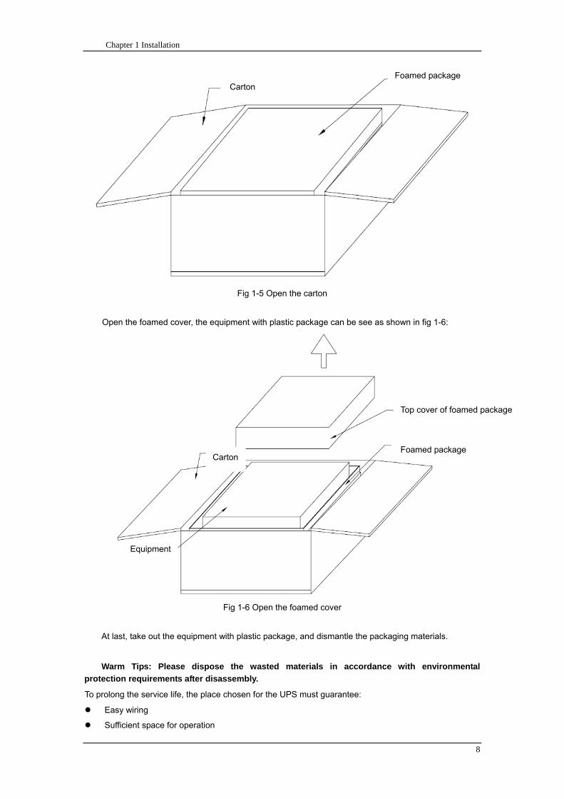
Chapter 1 Installation
8
Fig 1-5 Open the carton
Open the foamed cover the equipment with plastic package can be see as shown in fig 1-6
Fig 1-6 Open the foamed cover
At last take out the equipment with plastic package and dismantle the packaging materials
Warm Tips Please dispose the wasted materials in accordance with environmental
protection requirements after disassembly
To prolong the service life the place chosen for the UPS must guarantee
Easy wiring
Sufficient space for operation
CartonFoamed package
Carton
Equipment
Top cover of foamed package
Foamed package
Chapter 1 Installation
9
Air sufficient enough to dispel heat produced by UPS
Against ambient corrosive gases
Against excessive humidity and heat sources
Against dust
With the current fire prevention requirements
The operating environment temperature is within 20~25 The batteries are at maximum
efficiency in this temperature range (for information about the battery storage and transportation as
well as the environment please refer to table 6-2)
143 UPS Composition
UPS composition shall refer to fig 1-7 UPS configuration shall refer to table 1-1
功率模块
旁路模块
开关单元 配电单元
2m cabinet (front view) 2m cabinet (back view)
Bypass module
Power module
Distribution
unit
Switch unit
Chapter 1 Installation
10
开关单元
旁路模块
功率模块
配电单元
16m cabinet (front view) 16m cabinet (back view)
Fig 1-7 UPS Composition Diagram
Table 1-1 UPS Configuration Table
Involved part name Quantity (Piece) Note
Cabinet
Switch PDU 1 Standard configuration
Monitoring + bypass
module 1 Standard configuration
Power module Power module 1~6 or 1~10
Field installation is
required
144 Operation Space
As UPS has no ventilation grills at either sides no clearances are required for the sides
To enable routine tightening of power terminations within the cabinet it is recommended that
clearance around the front and back of the equipment should be sufficient to enable free passage of
personnel with the doors fully opened
145 Front and Back Access
The component layout of the UPS supports front and back access for servicing diagnosing and
repairing the UPS thus reducing the space requirement for side access
146 Final Positioning
When the equipment has been finally positioned ensure the adjustable feet are set so that the UPS
will remain stationary and stable
147 Power Module Installation
The installation position of power module and output distribution module are shown in fig 1-8 the
installation principle of these module is to installed from bottom to top to prevent inclination of the cabinet
due to high center of gravity
As is shown in fig 1-8 the installation procedure of power module is as follows
Switch unit
Bypass module
Power module
Distribution unit
Chapter 1 Installation
11
1 Each module shall be installed from bottom to top the default setting of the system is module No 1
2 3 4 5 6 7 8 9 and 10
2 Insert the module into installation position and push in the cabinet The wiring terminals in between
shall be tight and excessive force shall be prevented against the damage to inserted pins of the
terminals
3 Fix the module to the cabinet though the mounting holes on two sides of the front plate of the
module
固定孔
A处放大
Fig 1-8 Power Module Installation Diagram
148 Cable Entry
Cables can enter the UPS from top and below as shown in fig 1-9 Both the top and bottom of the
UPS have cable entrance
The recommended installation practice is to install power cables in the entrance channel
at both sides of the cabinet back door so as not to affect the ventilation
进线通道 进线通道
Fig 1-9 Cable Entry Diagram
Power module
Fixing hole
Amplification of A
Cable entrance Cable entrance
Chapter 1 Installation
12
15 Protective Devices
For safety concerns it is recommended to install external circuit breakers or other protective devices
for the input AC supply of the UPS system This section provides generic practical information for
qualified installation engineers The installation engineers should have the knowledge of the regulatory
wiring standards and of the equipment to be installed
151 Rectifier and Bypass Input Supply of the UPS
Install suitable protective devices in the distribution unit of the incoming mains supply considering
the power cable current-carrying capacity and overload capacity of the system (see Table 1)Generally
the magnetic circuit breaker with IEC60947-2 tripping curve C (normal) at the 125 of the current listed
in table 1-1 is recommended
Note
For IT power network system 4-pole protective device must be installed on the external input
distribution of the UPS
If protection against earth faults (RCD devices) is required for the upstream of the input supply the
installed device should
Sensitive to DC unidirectional pulses (class A) in the network
Insensitive to transient current pulses
Have an average sensitivity that is adjustable between 03A~1A
The RCCB must be sensitive to DC unidirectional pulses (class A) in the network while insensitive
to transient current pulses as shown in fig 1-10 respectively
Fig 1-10 RCCB sign
152 Battery
A battery unit is composed of 40 batteries connected in series a centreline is drawn from in
between (the joint part between the 20th and 21st battery) plus the line drawn from the front and back
there are altogether 3 lines connected with UPS line contact bank The battery line must push through a
DC circuit breaker before connecting to corresponding UPS line contact bank The detailed wiring please
refer to fig 1-11 below
Fig 1-11 Diagram of batteries connected in series
40 batteries connected in series
Chapter 1 Installation
13
153 UPS Output
A main output switch has been installed in UPS the user shall install the over current protective
device on the bypass of each output of the external distribution cabinet
16 Power Cables
Design the cables according to the descriptions in this section and local regulatory wiring standards
and the environmental conditions should be taken into consideration Refer to IEC60950-1 Table 3B
Warning
Prior to cabling the UPS confirm the status and positions of the switches of the UPS rectifier input
power supply bypass power supply and mains power distribution board
Ensure that these switches are opened and attached with WARNING label so as to prevent
unauthorized operation to these switches
161 Maximum stable state current and configuration of cable system please refer to
table 1-2
Table 1-2 Maximum stable state current and configuration of cable system
System Name MD-06010 MD-09015 MD-12020 MD-10010 MD-15015 MD-20020
Capacity
System
capacity 60kVA 90kVA 120kVA 100kVA 150kVA 200kVA
Module
capacity 10kVA 15kVA 20kVA 10kVA 15kVA 20kVA
Cabinet
dimension 6009001600(WDH mm) 6009002000(WDH mm)
Main
Input
Rated
current A 90 136 180 150 227 300
Cable mm2 25 35 50 50 75 75
Output
Rated
current A 90 136 180 150 227 300
Cable mm2 25 35 50 50 75 75
Battery
Rated
current A 106 160 212 178 265 355
Cable mm2 35 50 75 50 75 90
PE Cable mm2 35 50 75 50 75 90
Warning
FAILURE TO FOLLOW ADEQUATE EARTHING PROCEDURES CAN RESULT IN EMI ELECTRIC
SHOCK HAZARD OR RISK OF FIRE
Chapter 1 Installation
14
162 Cable Connection
Note
The operations described in this section must be performed by authorized electricians or qualified
technical personnel If you have any difficulties do not hesitate to contact our Customer Service amp
Support department at the address given at the beginning of this manual
After the equipment has been finally positioned and secured connect the power cables as
described in the following procedures
1 Verify that all the external input distribution switches of the UPS are completely opened and the
UPS internal maintenance bypass switch is opened Attach necessary warning signs to these
switches to prevent unauthorized operation
2 Open the back door of the cabinet remove the cover and then the input and output terminal
battery terminal and earth terminal are visible
3 Connect the input earth wire to input earth terminal Please note the earth wire shall be connected
in accordance with related local or state regulation
4 For common bypass and rectifier inputs connect the AC input supply cables to the UPS input
terminals (Main input A-B-C-N) and connect the output loaded cable to the UPS output terminals
(Output A-B-C-N) and tighten the connections to 13 Nm (M8 Bolt) ENSURE CORRECT PHASE
ROTATION
5 Connect the battery cables between the UPS battery terminals and battery switch ENSURE
CORRECT PHASE ROTATION
Warning-Hazardous battery terminal voltage of 400Vdc
Ensure the correct polarity connection between the battery terminals and the UPS terminals Positive
terminal to positive terminal negative terminal to negative terminal and disconnect one or more than
one cable between every two layers of batteries Do not connect the cables and close the battery
circuit breakers before getting the approval from the commissioning engineer
6 Re-install all the protective covers
17 Control and Communication Cabling
As shown in fig 1-12 the front panel of the bypass module will provide dry contact interface
(J2~J10) communication interface (RS232 485 and SNMP card interface) as well as LBS interface
干接点接口
SNMP卡接口
RS485接口
RS232接口LBS接口
Fig 1-12 Dry contact interface and communication interface
Dry contact
interface
SNMP card port
LBS port RS232 port
RS485 port
Chapter 1 Installation
15
The UPS accepts external signal from zero-voltage (dry) contacts connected through external dry
contact terminals produced and phoenix terminals that are in bypass module Through software
programming these signals become active when these contacts connect to +24V to ground)The cables
connected to DRY terminal must be separated from power cables Moreover these cables should be
double insulated with a typical 05 to 15 mm2
cross-section area for a maximum connection length
between 25 and 50 meters
171 Dry Contact Interface of Battery and Environmental Temperature Detection
The input dry contact J2 and J3 can detect the temperature of batteries and environment
respectively which can be used in environment monitoring and battery temperature compensation 1
J2 and J3 interfaces diagram are shown in fig 1-13 the description of interface is in table 1-3
Fig 1-13 Diagram of J2 and J3 dry contact for temperature detecting
Table 1-3 Description of input dry contact interface J2 and J3
Position Name Purpose
J21 TEMP_BAT Battery temperature detection
J22 GND Power ground
J31 TEMP_ENV Environment temperature detection
J32 GND Power ground
Note Specified temperature sensor is required for temperature detection (R25=5Ohm
B2550=3275) please confirm with the manufacturer or contact local maintenance engineers when
placing an order
172 Remote EPO Input Port
The UPS has an Emergency Power OFF (EPO) function This function can be activated by pressing
a button on the control panel of the UPS or through a remote contact provided by the user The EPO
pushbutton is protected by a hinged plastic cover
J4 is the input port for remote EPO It requires shorting NC and +24v during normal operation and
the EPO is triggered when opening NC and +24v or shorting NO and +24v The port diagram is shown in
fig 1-14 and port description is shown in table 1-4
Chapter 1 Installation
16
Fig 1-14 Diagram of input port for remote EPO
Table 1-4 Description of input port for remote EPO
Position Name Purpose
J41 EPO_NC EPO is activated when disconnecting fromJ42
J42 +12V +24V connect the common terminal of NC and NO
J43 +12V EPO is activated when shorting with J42
The EPO is triggered when shorting pin 2 and 3 or opening pin 2 and 1 of J4
If an external emergency stop facility is required it is connected via the reserved terminals of J4
The external emergency stop facility needs to use shielded cables to connect to the normally
openclosed remote stop switch between these two pins If this facility is not used then pin 3 and pin 4 of
J4 must be open or pin 1 and pin 2 of J4 must be shorted
Note
1 The emergency stop action within the UPS will shut down the rectifier inverter and static bypass
However it does not internally disconnect the mains input power supply To disconnect ALL power to
the UPS open the upstream input circuit breaker(s) when the EPO is activated
2 Pin 1 and 2 of J4 have been shorted before the UPS is delivered
173 Generator Input Dry Contact
J5 is status interface for generator connection Connect pin 2 of J5 with + 24 power supply it
indicates that the generator has been connected with the system The interface diagram is shown in fig
1-15 and interface description is shown in table 1-5
Chapter 1 Installation
17
Fig 1-15 Diagram of status interface and connection of generator
Table 1-5 Description of maintenance bypass switch and output switch status interface
Position Name Purpose
J51 +24V +24V power supply
J52 GEN Connection status of generator
J53 GND Power ground
174 BCB Input Port
J6 and J7 are the ports of BCB The port diagram is shown in fig 1-16 and description is shown in
table 1-6
BC
B_D
RV
BC
B_C
ON
T
J6 J7
BC
B_O
NL
+24V+24V
+24V
Fig 1-16 BCB Port
Table 1-6 Description of BCB port
Position Name Description
J61 BCB_DRV BCB actuating signal provide the actuating signal of +18V 20mA
J62 BCB_CONT BCB contact status connect with the normally open signal of BCB
J71 GND Power ground
J72 BCB_ONL BCB on-linendashinput (normally open) BCB is on-line when the signal
is connecting with GND
175 Battery Warning Output Dry Contact Interface
J8 is the output dry contact interface which outputs the battery warnings of low or excessive
voltage when the battery voltage is lower than set value an auxiliary dry contact signal will be
provided via the isolation of a relay The interface diagram is shown in fig 1-17 and description is
shown in table 1-7
Generator
Chapter 1 Installation
18
Fig 1-17 Battery warning dry contact interface diagram
Table 1-7 Battery warning dry contact interface description Position Name Purpose
J81 BAT_LOW_NC Battery warning relay (normally closed) will be open during warning
J82 BAT_LOW_NO Battery warning relay (normally open) will be closed during warning
J83 GND Center of battery warning relay
176 Integrated Warning Output Dry Contact Interface
J9 is the integrated warning output dry contact interface when one or more than one preset
warning is triggered the system will send an integrated warning information and provide an auxiliary
dry contact signal via the isolation of a relay The interface diagram is shown in fig 1-18 and description
is shown in table 1-8
Fig 1-18 Integrated warning dry contact interface diagram
Table 1-8 Integrated warning dry contact interface description Position Name Purpose
J91 ALARM_NC Integrated warning relay (normally closed) will be open during warning
J92 ALARM_NO Integrated warning relay (normally open) will be closed during warning
J93 GND Centre of integrated warning relay
177 Mains Failure Warning Output Dry Contact Interface
J10 is the output dry contact interface for mains failure warning when the mains fails the system
will send a mains failure warning information and provide an auxiliary dry contact signal via the isolation
of a relay The interface diagram is shown in fig 1-19 and description is shown in table 1-9
Chapter 1 Installation
19
Fig 1-19 Mains failure warning dry contact interface diagram
Table 1-9 Mains failure warning dry contact interface description Position Name Purpose
J91 UTI_FAIL_NC Mains failure warning relay(normally closed) will be open during
warning
J92 UTI_FAIL_NO Mains failure warning relay normally open) will be closed during
warning
J93 GND Centre of mains failure warning relay
178 RS232 Port and SNMP Card Port
RS232 and RS485 Port provide serial data which can be used for commissioning and maintenance
by authorized engineers or maintainers or can be used for networking or integrated monitoring system in
the service room
SNMP Card Port used for field installation of the communication option card(SNMP card)
179 LBS (Load Bus Synchronizer) Port
The dual bus system (DBS) consists of two independent UPS rack module systems as shown in fig
1-20 The dual bus system is configured for high availability and is suitable for powering the load with
dual inputs If the load is single-input load the static transfer switch and LBS control is recommended to
maintain both UPS outputs synchronized for uninterrupted transfers Please install the system according
to the installation descriptions for different system configurations
The dual bus system is supported by UPS it requires connecting the LBS signal cables of two UPS
when constructing the dual bus system please refer to relevant chapter for detailed configuration and
installation and the system software shall be configured as required
UPS 1
LBS
监控旁路模块 UPS 2
LBS
监控旁路模块
Fig 1-20 LBS Connection Diagram
18 Installation Drawing
Please refer to fig 1-21 fig 1-22 fig 1-23 and fig 1-24
UPS 1 monitoring bypass module
UPS 2 monitoring bypass module
Chapter 1 Installation
20
Fig 1-21 Installation Diagram
Chapter 1 Installation
21
顶视图
2m cabinet front view
16 m cabinet (front view)
Fig 1-22 UPS front view (Unit mm)
Top view
Chapter 1 Installation
22
A
2m cabinet
A
16m cabinet
Fig 1-23 UPS back view
Chapter 1 Installation
23
A
A处放大
Fig 1-24 UPS front view
Amplification of A
24 Chapter 2 Operations
24
Chapter 2 Operations
This chapter introduces the basic knowledge of UPS operations including working principle
operation mode battery management and protection
Warning Hazardous mains voltage andor battery voltage present(s)behind the protective cover
The components that can only be accessed by opening the protective cover with tools cannot be
operated by user
Only qualified service personnel are authorized to remove such covers
21 Introduction
UPS provides the critical load (such as communication and data processing equipment) with high
quality uninterruptible AC power The power from UPS is free from voltage and frequency variations and
disturbances (interruption and spike) experienced at the Mains AC input supply
This is achieved through high frequency double conversion power pulse width modulation (PWM)
associated with full digital signal processing control (DSP) which features high reliability and
convenience for use
211 Principle
As shown in fig 2-1 the AC input mains source is supplied at UPS input and converted into a DC
source This DC source feeds the Inverter that converts the DC source into a clean and input
independent AC source The battery powers the load through the inverter in case of an AC input mains
power failure The utility source can also power the load through the static bypass
When the UPS needs maintenance or repair the load can be transferred to maintenance bypass
without interruption and the power module and bypass module can be removed for maintenance
Chapter 2 Operations 25
25
Fig 2-1 System principle framework
212 Bypass Module
The circuit blocks labeled ldquobypass modulerdquo in fig 2-1 contain electronically controlled switching
circuits that enable the critical load to be connected to either the inverter output or to a bypass power
source via the static bypass line During normal system operation the load is connected to the inverter
but in the event of a UPS overload or inverter failure the load is automatically transferred to the static
bypass line
To provide a clean (no-break) load transfer between the inverter output and static bypass line the
inverter output and bypass supply must be fully synchronized during normal operating conditions This is
achieved through the inverter control electronics which makes the inverter frequency track that of the
static bypass supply provided that the bypass remains within an acceptable frequency window
A manually controlled maintenance bypass supply is incorporated into the UPS design It enables
the critical load to be powered from the utility (bypass) supply while the UPS is shut down for routine
maintenance
Note
When the UPS is operating in bypass mode or on maintenance bypass the connected equipment is
not protected from power failures or surges and sags
22 Operation Mode
The MD UPS is an on-line double-conversion reverse-transfer UPS that permits operation in these
modes
Normal mode
26 Chapter 2 Operations
26
Battery mode
Auto-Restart mode
Bypass mode
Maintenance mode (manual bypass)
ECO mode
Frequency converters mode
221 Normal Mode
The UPS inverter power modules continuously supplies the critical AC load The rectifiercharger
derives power from the AC mains input source and supplies DC power to the inverter while
simultaneously FLOAT or BOOST charging its associated backup battery
222 Battery Mode
Upon failure of the AC mains input power the inverter power modules which obtains power from the
battery supplies the critical AC load There is no interruption in power to the critical load upon failure
After restoration of the AC mains input power the ldquoNormal Moderdquo operation will continue automatically
without the necessity of user intervention
Note UPS can also be started through battery (charged) mode via battery cold start function upon
failure of the AC mains Therefore the battery power can be used independently to improve the
utilization rate of UPS
223 Auto-Restart Mode
The battery may become exhausted following an extended AC mains failure The inverter shuts
down when the battery reaches the End of Discharge voltage (EOD) The UPS may be programmed to
ldquoAuto Recovery after EODrdquo after a delay time if the AC mains recovers This mode and any delay time
are programmed by the commissioning engineer
During the process of delay time the battery will be charged by UPS to prevent any risks to load
equipment from future mains failure
224 Bypass Mode
If the inverter overload capacity is exceeded under normal mode or if the inverter becomes
unavailable for any reason the static transfer switch will perform a transfer of the load from the inverter
to the bypass source with no interruption in power to the critical AC load
225 Maintenance Mode
A manual bypass switch is available to ensure continuity of supply to the critical load when the UPS
becomes unavailable eg during a maintenance procedure
Note This manual bypass switch is fitted in all UPS modules Transfer UPS system to bypass
module for power supply first then close maintenance bypass switch Q2 followed by Q1 and Q3
Warning hazard may occur after transferring to maintenance bypass
After UPS being transferred to maintenance bypass power module and bypass module do not work
no display on LCD and input and output terminals as well as N bus are electrically connected
Chapter 2 Operations 27
27
226 ECO Mode
If economical (ECO) mode is selected the double-conversion UPS will stop to work so as to save
energy During the operation of ECO mode the load power will be supplied by bypass preferentially
When bypass power is within the range of normal frequency and voltage load power will be supplied by
bypass or the system will transfer to inverter input followed by load power interruption which extends
within 34 of the utility period Eg when the frequency is 50Hz the interruption time will be less than
15ms when the frequency is 60Hz the time will be less than 125ms
227 Frequency Converters Mode
If the frequency converter configuration is used by UPS it will provide 50Hz or 60Hz stable output
frequency The range of output frequency is 40Hz~70Hz Under this mode static bypass is unavailable
but battery can be selected according to the actual requirements of battery mode
23 Battery Management
231 Normal Function
The following functions should be fitted by commissioning engineers with specified software
1 Constant current boost charging
Current can be set up
2 Constant voltage boost charging
Voltage of boost charging can be set as required by the type of battery
For Valve Regulated Lead Acid (VRLA) batteries maximum boost charge voltage should not
exceed 24V cell
3 Float charge
Voltage of float charging can be set as required by the type of battery
For VRLA float charge voltage should be between 22V to 23V
4 Float charge temperature compensation (optional)
A coefficient of temperature compensation can be set as required by the type of battery
5 End of discharge (EOD) protection
If the battery voltage is lower than the EOD the battery converter will shut down and the battery is
isolated to avoid further battery discharge EOD is adjustable from 16V to 175V per cell (VRLA) or 09
to 11 V per cell
6 Battery low warning time
It is adjustable between 3 and 60 minutes The default is 5 minutes
232 Advanced Functions (Battery Self-checking and Maintenance)
At periodic intervals 20 of the rated capacity of the battery will be discharged automatically and
the actual load must exceed 20 of the rated UPS (KVA) capacity If the load is less than 20
auto-discharge cannot be executed The periodic interval can be set from 30 to 360 days The battery
self-test can be disabled
ConditionsmdashBattery at float charge for at least 5 hours load equal to 20~100 of rated UPS capacity
TriggermdashManually through the command of ldquoBattery Maintenance Testrdquo in LCD panel or automatically
Battery Self-Test Intervalmdash30-360 days (default setting is battery self-test disabled)
28 Chapter 2 Operations
28
24 Battery Protection
The following functions should be fitted by commissioning engineers with specified software
1 Battery Low Pre-warning
The battery under voltage pre-warning occurs before the end of discharge After this pre-warning
the battery should have the capacity for 3 remaining minutes discharging with full load The time is user
configured from 3 to 60 minutes
2 Battery discharge (EOD)off protection
If the battery voltage is lower than the EOD the battery converter will be shut down EOD is
adjustable from 16V to 175V per cell (VRLA) or 09 to 11 V per cell (NiCd)
3 Battery Circuit Breaker (BCB) Alarm
The alarm occurs when the battery disconnect device disconnects The external battery connects to
the UPS through the external battery circuit breaker The circuit breaker is manually closed and tripped
by the UPS control circuit
Chapter 3 Operation Instructions 29
29
Chapter 3 Operating Steps
This chapter describes UPS operation instructions in detail
All functional keys and LED display involved in operation instructions please refer to chapter 4
During operation the buzzer alarm may occur at any time Select ldquomuterdquo on LED to muffle the audible
alarm
Warning-Hazardous mains voltage andor battery voltage present(s)behind the protective cover
1 The components that can only be accessed by opening the protective cover with tools cannot be
operated by user
2 Only qualified service personnel are authorized to remove such covers
31 Power Switches
As shown in fig 3-1 open the front door of UPS the power switch is visible which includes input
switch output switch and maintenance bypass switch (with anti-misoperation stop plate)
输入开关 输出开关
维修旁路开关
Fig 3-1 Power switch location diagram
32 UPS Start-up
The UPS system only has a maintenance bypass isolating switch and all the other transfers are
processed automatically by internal control logics
Input switch Output switch
Maintenance bypass switch
30 Chapter 3 Operating Instructions
30
321 Normal Module Start
This procedure must be followed when turning on the UPS from a fully powered down condition
The operating procedures are as follows
Warning
This procedure results in mains voltage being applied to the UPS output terminals If any load
equipment is connected to the UPS output terminals please check with the load user that it is safe to
apply power If the load is not ready to receive power then ensure that it is safely to close the output
switch of external distribution cabinet
1 Close UPS output switch and input switch in turns
The LCD starts up at this time The Rectifier indicator flashes during the startup of rectifier The
rectifier enters normal operation state and after about 30s the rectifier indicator goes steady green After
initialization the bypass static switch closes The UPS Mimic LEDs will indicate as shown in table 3-1
Table 3-1 Indicator status
LED Status
Rectifier indicator Green
Battery indicator Red
Bypass indicator Green
Inverter indicator Off
Load indicator Green
Status indicator Green
Note
The output circuit breaker must be closed first followed by input circuit breaker or the rectifier cannot
be started and alarm ldquorectifier failurerdquo
The inverter starts up at this time the inverter indicator flashes After the rectifier enters normal
operation state UPS power supply will transfer from bypass to inverter then the bypass indicator turns
off and load indicator lights The status of indicators is shown in table 3-2
Table 3-2 Indicator Status
LED Status
Rectifier indicator Green
Battery indicator Red
Bypass indicator Off
Inverter indicator Green
Load indicator Green
Status indicator Green
Close external battery switch again battery indicator turns off a few minutes later the battery will be
charged by UPS which will enter normal mode operation The indicator status is shown in table 3-3
Table 3-3 Indicator status
LED Status
Rectifier indicator Green
Battery indicator Green
Bypass indicator Off
Inverter indicator Green
Load indicator Green
Status indicator Green
322 Operating steps of Battery cold Start
1 Check if the batteries have been connected close the external battery switch
Chapter 3 Operation Instructions 31
31
2 Press the red start-up button of battery under the rectifier input circuit breaker for 3 seconds (see fig
3-2)
The LCD starts up at this time The green battery indicator flashes The rectifier enters normal
operation states and after about 30s the battery indicator goes steady green
3 The inverter starts up automatically the green inverter indicator flashes The output of inverter
appears after 60s The UPS works on battery mode
32 Chapter 3 Operating Instructions
32
电池启动按钮
Fig 3-2 Position diagram of battery startup button
Battery startup button
Chapter 3 Operation Instructions 33
33
33 Procedure for Switching between Operation Modes
331 Procedure for Switching the UPS into Battery mode from Normal Mode
Open input switch to cut off the mains UPS enters the battery mode If UPS should be switched to
normal mode wait for a few seconds before close input switch so as to supply the mains again 10s
later the rectifier will start up automatically to supply power to the inverter
332 Procedure for Switching the UPS into Bypass mode from Normal Mode
Select ldquoTran Byprdquo on the LCD or press ldquooffrdquo buttons of each power module in turn
Note
In bypass mode the load is directly fed by the mains power instead of the pure AC power from the
inverter
333 Procedure for Switching the UPS into Normal from Bypass Mode
Select exit bypass mode on the LCD
334 Procedure for Switching the UPS into a Maintenance Bypass from Normal Mode
In normal operation this operation instruction will switch the load from inverter input to maintenance
bypass
Caution
Before making this operation read messages on display to be sure that bypass supply is regular and
the inverter is synchronous with it so as not to have a risk of a short interruption in powering the load
1 Press ldquoTran Byprdquo on the LCD or press ldquooffrdquo on each power module in turns
If press rdquoTran Byprdquo on the LCD the inverter indicator will flash green and the buzzer will alarm
If press ldquooffrdquo on each power module in turns the inverter indicator will go off and the buzzer will
alarm
The load will be transferred to static bypass and the inverter is closed
2 Close maintenance bypass switch Q2 the load power will be supplied by maintenance bypass and
then open the inverter circuit breaker Q1 output switch Q3 and battery switch
Warning
If you need to maintain the module wait for 10 minutes to let the DC bus capacitor fully discharge
before removing corresponding module
335 Procedure for Switching the UPS into Normal from a Maintenance Bypass Mode
This procedure can transfer the load to normal main mode when the UPS is operating under the
maintenance bypass mode
1 Close output switch Q3 and main switch Q1
The bypass indicator goes green and the load power will be supplied by bypass and maintenance
bypass
2 Open maintenance bypass switch Q2
34 Chapter 3 Operating Instructions
34
The load power is supplied by bypass In the meantime the rectifier starts up rectifier indicator goes
green 30s later at this time the inverter will start up automatically and transfer to inverter mode 1 min
later automatically
3 Close external battery switch the battery indicator goes off Check if the battery voltage on LCD
display is normal
34 Procedure for Completely Powering down a UPS
If you need to power down the UPS completely follow the procedures in section 334 to transfer the
UPS from normal mode to maintenance bypass mode
If you need to isolate the UPS from the AC power supply you should open the external input switch
35 EPO Procedure
The EPO button on UPS operator control and display panel is designed to switch off the UPS in
emergency conditions (eg fire flood etc)To achieve this just press the EPO button and the system
will turn off the rectifier inverter and stop powering the load immediately (including the inverter and
bypass output) and the battery stops charging or discharging
If the input utility is present the UPS control circuit will remain active however the output will be
turned off To completely isolate the UPS you need to open the external mains input supply to the UPS
rack
36 Language Selection
The LCD is available in two languages Chinese English and Korean
The language can be selected through LCD prompt window
37 Control Password
When the LCD displays ldquoinput control password 1rdquo the initial password is 12345678
Chapter 4 Operator Control and Display Panel 35
35
Chapter 4 Operator Control and Display Panel
This chapter introduces the functions and operation instructions of the parts on UPS operator control
and display panel in detail and provides LCD display information including LCD display types detailed
menu information prompt window information and UPS alarm list
41 Introduction
The operator control and display panel is located on the front panel of the UPS Through this LCD
panel the operator can operate and control the UPS and check all measured parameters UPS and
battery status and event and alarm logs The operator control panel is divided into three functional areas
as shown in fig 4-1 mimic current path LCD display amp Menu keys and Control and Operation Keys The
detailed description of parts on operator control and display panel is shown in table 4-1
Fig 4-1 UPS operator control and display panel
Table 4-1 Description of UPS operator control and display panel
Part No Function Button Function
REC Rectifier indicator EPO EPO switch
BAT Battery indicator TAB switch
BYP Bypass indicator ENTER confirm
INV Inverter indicator ESC exit
OUTPUT Load indicator
STATUS Status indicator
36 Chapter 4 Operator Control and Display Panel
36
411 LED Indicator
The LEDs shown on the mini current path represent the various UPS power paths and show the
current UPS operating status The status description of indicators is shown in table 4-2
Table 4-2 Status description of indicator
Indicator State Purpose
Rectifier
indicator
Steady green Rectifier normal for all modules
Flashing green Rectifier for at least on module normal mains normal
Steady red Rectifier fault
Flashing red Mains abnormal for at least one module
Off Rectifier not operating
Battery
indicator
Steady green Battery charging
Flashing green Battery discharging
Steady red
Battery abnormal (battery failure no battery or battery reverse) or
battery converter abnormal (failure over current or over temperature)
EOD
Flashing red Battery low voltage
Off Battery and battery converter normal battery not charging
Bypass
indicator
Steady green Load power supplied by bypass
Steady red Bypass power abnormal or out of normal range or static bypass
switch fault
Flashing red Bypass voltage abnormal
Off Bypass normal
Inverter
indicator
Steady green Load power supplied by inverter
Flashing green Inverter On start synchronization of standby (ECO mode) for at least
one module
Steady red System power not supplied by inverter inverter fault for at least one
module
Flashing red System power supplied by inverter inverter fault for at least one
module
Off Inverter not operating for all modules
Load
indicator
Steady green UPS output ON and normal
Steady red UPS output overload and overtime or output short or output no power
supply
Flashing red Overload output of UPS
Off No output of UPS
Status
indicator
Steady green Normal operation
Steady red Failure
412 Audible Alarm (buzzer)
There are two different types of audible alarm during UPS operation as shown in table 4-3
Table 4-3 description of audible alarm
Alarm Purpose
Two short alarm with
a long one
when system has general alarm (for example AC fault) this audible alarm
can be heard
Continuous alarm When system has serious faults (for example fuse or hardware fault) this
audible alarm can be heard
Chapter 4 Operator Control and Display Panel 37
37
413 Functional Keys
There are 4 functional keys on operator control and display panel which are used together with LCD
The functions description is shown in table 4-4
Table 4-4 Functions of functional keys
Functional key Functions
EPO switch To cut off the load power to shut down the rectifier inverter static
bypass and battery
TAB switch
ENTER confirm
ESC exit
42 LCD Display Type
Following the self-check of UPS LCD display the main LCD display is shown as fig 4-2 which can
be divided into three display windows system information data command and current record
Fig 4-2 Main LCD display
The description of LCD icon is shown in table 4-5
Table 4-5 Description of LCD icons
Icon Description
Bypass parameter
UPS system
information
window
Data
command
window
Current
record
window
38 Chapter 4 Operator Control and Display Panel
38
Icon Description
Main input parameter
History file system information
Function setting (display calibration password setting time setting date format
communication protocol and language setting) system setting (used by product
maintainers)
Battery data battery parameter setting (used by service staff)
Test (battery self-test battery maintenance)
Functional keys used by service staff (fault clearing history file clearing noise
clearing manual switch of bypass) userrsquos setting (system mode machine
number system ID output voltage adjustment frequency tracing speed
frequency tracing limit)
Output parameter
Load
Noise clearing noise clearing cancel
Log view page updown
Select a icon on LCD as shown in fig 4-3 to view the UPS parameter represented by this icon eg
select the LCD will display the data of system main input
Chapter 4 Operator Control and Display Panel 39
39
Fig 4-3 Select data
Or select and confirm a module as shown in fig 4-4 the LCD will display the
operating status of this module
Fig 4-4 Select a module
40 Chapter 4 Operator Control and Display Panel
40
Select in the operating status of a module to view the main input data of this module
Select in the operating status of a module to view the main output data of this module
Select in the operating status of a module to view the load data of this module
Select in the operating status of a module to view the maintenance code and module
software code of this module
Select to return to the previous page
Select to return to the home page
Default display
During the operation of system if therersquos no alarm in 2 min the system will display default After a
short delay the backlight of LCD display goes off press any key to reactivate the display
43 Detailed Description of Menu Items
The LCD main display shown in fig 4-2 is described in details below
UPS information window
UPS information window display the current time and UPS name The information of the window is
not necessary for the user to operate The information of this window is given in table 4-6
Table 4-6 Description of items in UPS system information window
Display contents Meaning
MD12020 UPS Name
1200 Current Time (format 24 hours hours minute)
UPS menu and data window
UPS menu window displays the menu name of data window while the data window displays the
related contents of selected menu in menu window Select UPS menu and data window to browse
related parameters of UPS and set related functions The details are given in table 4-7
Table 4-7 Item description of UPS menu and data window
Menu name Menu item Meaning
Main input
V phase(V) V phase
I phase(A) I phase
Freq(Hz) Input frequency
PF Power factor
Bypass input
V phase(V) V phase
Freq (Hz) Bypass frequency
I phase(A) I phase
PF Power factor
AC output
V phase(V) V phase
I phase(A) I phase
Freq (Hz) Output frequency
PF Power factor
This UPS Sout (kVA) Sout Apparent Power
Chapter 4 Operator Control and Display Panel 41
41
Menu name Menu item Meaning
modulersquos
load
Pout (kW) Pout Active Power
Qout (kVAR) Qout Reactive Power
Load () Load (The percentage of the UPS rating load)
Battery data
Environmental
Temp Environmental Temp
Battery
voltage(V) Battery bus voltage
Battery current
A) Battery bus current
Battery
Temp() Battery Temp
Remaining Time
(Min) Remaining battery backup time
Battery capacity
() The percentage compared with new battery capacity
battery
equalized
charging
Battery is equalized charging
battery float
charging Battery is float charging
Battery
disconnected Battery is not connected
Current
record (current alarm)
Display all current alarm The alarm list displayed on LCD of
UPS operator control and display panel please refer to table 4-9
History
record (history alarm)
Display all history alarm The alarm list displayed on LCD of
UPS operator control and display panel please refer to table 4-9
Menu
Language
(language
option) 2 languages can be selected
Settings
Display
calibration Adjust the accuracy of LCD display
Date format set MM DD YYYY and YYYY MM DD formats can be selected
Date amp Time DateTime set
Language set User can set the language (Chinese and English)
Communication
mode
Set communication mode MODBUS Power protocol and
company custom protocol modes can be selected Power
protocol mode can be divided into equipment address baud
rate set MODBUS protocol mode can be divided into
communication mode (RTUASCⅡ) equipment address
baud rate and check-bit set Company custom protocol mode
is the customed protocol of the company no option is
available
Control
password set User can modify control password 1
Test
Command
(Battery Test
Control
Battery
maintenance
test
This test will lead to the battery being partly discharged to
activate battery at the same time the approximate battery
capacity will be obtained Bypass must be in normal condition
the battery capacity should be above 25
42 Chapter 4 Operator Control and Display Panel
42
Menu name Menu item Meaning
Battery
self-check test
UPS switches to battery discharge for discharging to test if the
battery is normal Bypass must be in normal condition the
battery capacity should be above 25
Stop testing Manually Stop the test including maintenance test capacity test
UPS system
information
Monitoring
software version Provide monitoring software version
Rectified
software version Provide rectified software version
Inverted
software version Provide inverted software version
Serial No The serial no set when delivery from the factory
Rated
information Network setting of system operating
Module type Type of the module
44 Alarm List
The follow table 4-8 gives the complete list of all the UPS events displayed by history record window
and current record window
Table 4-8 Alarm List
Alarm Explanation
UPS power supply The system is in normal inverted power supply status
Bypass power
supply The system is in bypass power supply status
No power supply System no output
Battery equalized
charging Battery is in boost charging
Battery float
charging Battery is in float charging
Battery discharging The system is operating in battery discharging status
Battery connected Battery is connected
Battery
disconnected Battery is not connected
Maintenance circuit
breaker close Maintenance circuit breaker is close
Maintenance circuit
breaker open Maintenance circuit breaker is open
Emergency
shutdown System emergency shutdownEPO
Generator
connected External generator is connected
Mains abnormal Input mains abnormal
Bypass phase
conversion Bypass input phase converse
Bypass voltage
abnormal Bypass input voltage abnormal
Bypass fault Bypass fault
Bypass overload Bypass output is overload
Up to bypass
overtime of Bypass is overtime of overload
Chapter 4 Operator Control and Display Panel 43
43
Alarm Explanation
overload
Bypass frequency
tracing exceeds Bypass frequency is out of the tracing range
Switch times up to
in this hour
The times of switch between bypass and inverter exceeds 5 times in the latest
hour
Output short System output short
Battery EOD Battery voltage achieves shutdown point
Battery self-check The system enters battery self-check mode
Battery self-check
success Battery normal during system self-check
Battery manual
check failure Battery fault during system self-check
Battery
maintenance The system is in battery maintenance status
Battery
maintenance
success
Battery maintenance status completes
Battery
maintenance failure Battery maintenance process is not normal
Stop testing Battery self-check or battery maintenance status stops
Fault clearing Clear the alarmed fault
Delete history
record Delete all history record
N communication
node connected N module is connected to UPS system
N communication
node disconnected N module is not connected to UPS system
N rectifier fault N module rectifier fault
N inverter fault N module inverter fault
N rectifier
overheat N module rectifier overheat
N fan fault N module fan fault
N output overload N module output overload
N overtime of
overload N module output overtime of overload
N inverter
overheat N module inverter overheat
Inverter power
supply ban Inverter power ban supply
Manual switch of
bypass Switch the system to bypass output manually
Cancel manual
switch of bypass Switch the system from bypass to inverter output manually
Battery low voltage Battery low voltage
Battery reversal Battery polarity reversal
N inverter
protection N module inverter protection
Input N line
disconnected System input N line is not connected
Bypass fan fault Bypass module fan fault
N manual N module manual power off
44 Chapter 4 Operator Control and Display Panel
44
Alarm Explanation
shutdown
Chapter 5 Maintenance 45
45
Chapter 5 Installation of Parallel Operation System
The parallel operation system is installed as required by the installation procedures of the single
system and this chapter
The single devices are put parallel and connected as shown in fig 5-1 and the difference between
the lengths of the output cables of the single devices is not more than 10m It is recommended to use an
external bypass cabinet to facilitate maintenance and system testing
Fig 5-1 Typical 1+N parallel operation system
Note when the load exceeds is the capacity of the single device the maintenance bypass
switch CB3 must be removed
The cables for the parallel operation provide double insulation shielding up to 30m long the control
cables for the parallel operation must be connected with all single devices to form a closed loop as
shown in fig5-2
Other power supplies
Rectifier
Charger Inverter Inverter
Output power supply
Load connected
Mains power input L1 L2 L3 N terminal
Mains power inputL1 L2 L3 N terminal
Rectifier
Charger
46 Chapter 5 Maintenance
46
Fig5-2 parallel cables
Chapter 5 Maintenance 47
47
Chapter 6 Maintenance
This chapter introduces UPS maintenance including the maintenance instructions of power module
monitoring bypass module and the change method of dust filter
61 Instruction to Power Bypass and Output Power Distribution
Module
611 Precautions
1 Only maintaining engineers can maintain the power module and monitoring bypass module
2 In principle the power module and bypass module should be disassembled from top to bottom so
as to prevent any inclination from high gravity centre of the cabinet
3 To ensure the safety before maintaining power module and bypass module be sure to use a
multimeter to measure the DC bus capacitor voltage and ensure the voltage is below 60V before
operation and use a multimeter to measure the voltage between operating parts and the earth to
ensure the voltage is lower than hazardous voltage ie DC voltage is lower than 60Vdc and AC
maximum Voltage is lower than 424Vac
4 Bypass module doesnrsquot support any hot insertion and extraction only when UPS is in maintenance
bypass mode or UPS is completely power off can the bypass module be disassembled
5 The module can be maintained 10 mins after extracting power module and bypass module which
can be inserted into the cabinet 10 mins later
612 Instruction to Power Module
Suppose UPS were in normal mode and bypass were normal a module shall be maintained at
first
1 Press OFF of the module with a pin point or other tiny matter the module will shut down
automatically and exit the system
Note ensure if the remaining module will be overload when exiting a module If therersquos any risk of
overload transfer the whole UPS system to bypass followed by other operations
2 Take off the fixing bolt on the two sides of front and back plate of power module 10 mins later
extract the module from the cabinet
3 After maintaining the module push the module into the equipment cabinet (the interval between
two modules shall be more than 10s) fix the screw on the two sides Then the module will be
connected to UPS system automatically
613 Instruction to Bypass Module
Suppose UPS were in normal mode and the bypass were normal
1 Select LCD touch screen manual switch of bypass the UPS power will be supplied by bypass
2 Close maintenance bypass switch the UPS power will be supplied by maintenance bypass
3 Open UPS output switch and input switch
4 Open external battery switch
48 Chapter 5 Maintenance
48
5 Take off the fixing bolt at the two sides of front board of bypass module extract the front cable
assembly of the module and extract the module from the cabinet
6 After maintaining the module insert the module into the cabinet tighten the screw at the two sides
and connect the front cable assembly of manufacturerrsquos module
7 Close UPS output switch and input switch in turn
2 mins later bypass indicator on the operator control and display panel lights on which indicates
the normal power supply of bypass
8 Open maintenance bypass switch the inverter starts automatically 60s later the UPS will transfer
to normal mode
62 Replacing Dust Screen (optional)
As shown in fig 5-1 there are 3~4 dust filters on the back of UPSrsquo front door each screen is held in
place by a bracket on either side of each filter The procedure of replacing each filter is as follows
1 Open the UPSrsquo front door and locate the filters on the back side of the front door
2 Remove one bracket
3 Remove the dust screen to be replaced and insert the clean one
4 Reinstall the bracket
防尘网固定条
Fig 5-1 Dust screen on the back side of UPS front door
Bracket
Dust screen
Appendix 2 Toxic or Hazardous Materials or Elements Identification Table 49
49
Chapter 7 Product Specification
This chapter provides UPS product specification
71 Applicable Standards
The UPS has been designed to conform to the following European and international standards
Table 6-1 Compliance with European and International Standards
Item Normative reference
General safety requirements for UPS
used in operator access areas EN50091-1-1IEC62040-1-1AS 62040-1-1
Electromagnetic compatibility (EMC)
requirements for UPS EN50091-2IEC62040-2AS 62040-2(C3)
Method of specifying the performance
and test requirements of UPS EN50091-3IEC62040-3AS 62040-3(VFI SS 111)
Note The above mentioned product standards incorporate relevant compliance clauses with generic
IEC and EN standards for safety (IECENAS60950) electromagnetic emission and immunity
(IECEN AS61000 series) and construction (IECENAS60146 series and 60950)
72 Environmental Characteristics
Table 6-2 Environmental Properties
Items Unit Requirements
Acoustic noise level at 1
meter dB 550
Altitude of Operation m le1000m above sea level derate power by 1 per 100m
between 1000m and 2000m
Relative Humidity RH 0 to 95 non condensing
Operating Temperature 0 to 40 deg Battery life is halved for every 10degC increase
above 20degC
UPS Storage-Transport
Temperature -20~70
Recommended Battery
Storage Temperature -20~30 (20degC for optimum battery storage)
73 Mechanical Characteristics
Table 6-3 Mechanical Properties
Cabinet Specification Unit MD6010 MD9015
MD12020
MD10010 MD15015
MD20020
Mechanical Dimension
WtimesDtimesH mm 600times900times1600 600times900times2000
Weight kg 151 182
Color NA Black
Protection Level
IEC(60529) NA IP20
50 Chapter 5 Maintenance
50
Module type Unit MU10 MU15 MU20
Mechanical Dimension
WtimesDtimesH mm 440times590times134
Weight kg 21 22 22
Color NA Black
74 Electrical Characteristics (Input Rectifier)
Table 6-4 Rectifier AC input (mains)
Items Unit Parameter
Rated AC Input
Voltage Vac
380400415(three-phase and sharing neutral with the
bypass input)
Input voltage range Vac -40~+25
Frequency2 Hz 5060(range 40Hz~70Hz)
Power factor kWkVA full load 099
THD THDI 3
75 Electrical Characteristics (Intermediate DC Link)
Table 6-5 Battery
Items Unit Parameters
Battery bus
voltage Vdc Nominal plusmn240V one-side range 198V~288V
Quantity of
lead-acid cells Nominal 40=[1 battery(12V) ] 240=[1 battery(2V) ]
Float charge
voltage Vcell(VRLA)
225Vcell(selectable from 22Vcell~235Vcell)
Constant current and constant voltage charge mode
Temperature
compensation mVcl -30(selectable from 0~-50 25 or 30 or inhibit)
Ripple voltage V float le1
Ripple current C10 le5
equalized
charge voltage VRLA
24Vcell(selectable from 230Vcell~245Vcell)
Constant current and constant voltage charge mode
final
discharging
voltage
Vcell(VRLA)
165Vcell(selectable from 160Vcell ~ 1750Vcell) 06C
discharge current
175Vcell (selectable from 165Vcell ~ 18Vcell) 015C
discharge current
(EOD voltage changes linearly within the set range according to
discharge current)
Battery Charge Vcell 24Vcell(selectable from 23Vcell~245Vcell)
Constant current and constant voltage charge mode
Battery
Charging Power
Max Current
kW 10 UPS capacity (selectable from 0~20 UPS capacity)
Appendix 2 Toxic or Hazardous Materials or Elements Identification Table 51
51
76 Electrical Characteristics (Inverter Output)
Table 6-6 Inverter Output (to important load)
Rated
capacity(kVA) Unit 10~200
Rated AC voltage1 Vac 380400415(three-phase four-wire and sharing neutral with the
bypass)
Freqency2 Hz 5060
overload
110 load 1 hour
125 load 10min
150 load 1min
>150 load 200ms
Fault current 340 short current limitation for 200ms
Non linear load
capability 3 100
Neutral current
capability 170
Steady state
voltage stability
plusmn1(balanced load)
plusmn15(100 imbalance load)
Transient voltage
response 4 plusmn5
THD <15(linear load) <5(non linear load3)
Synchronization -
Window Rated frequency plusmn2Hz(selectable plusmn1~plusmn5Hz)
Max change rate of
synch frequency Hzs 1 selectable 01~5
Inverter voltage
range V(ac) plusmn5
Note
1 Factory setting is 380V Commissioning engineers can set to 400V or 415V
2 Factory setting is 50Hz Commissioning engineers can set to 60Hz
3 EN50091-3(1458) peak value factor is 3 1
4 IEC62040-3EN50091-3 including 0~100~0 load transient the recovery time is half
circle to within 5 of stable output voltage
52 Chapter 5 Maintenance
52
77 Electrical Characteristics(Bypass Mains Input)
Table 6-7 Bypass Mains Input
Rated
capacity(kVA) Unit 60 90 100 120 150 200
Rated AC
Voltage1 Vac
380400415
three-phase four-wire sharing neutral with the rectifier input and providing neutral
reference for the output
Rated current A
91380V
87400V
83415V
136380V
130400V
124415V
151380V
144400V
138415V
182380V
174400V
166415V
227380V
216400V
207415V
302380V
288400V
276415V
Overload
125 load long term
130 load 1 hour
150 load 6min
1000 load 100ms
Superior
protection
bypass line
NA Thermal-magnetic breaker the capacity is 125 of rated current output
IEC60947-2 curve C
Current rating
of neutral cable A 17timesIn
Frequency2 Hz 5060
Switch time
(between
bypass and
inverter)
ms Synchronized switch le1ms
Bypass voltage
tolerance Vac
Upper limit +10+15or+20 default +20
Lower limit -10 -20 -30 or-40 default-20
(acceptable stable bypass voltage delay 10s)
Bypass
frequency
tolerance
plusmn25 plusmn5 plusmn10 or plusmn20 default plusmn10
Synchronizatio
n-Window Hz Rated frequencyplusmn2Hz (selectable from plusmn05Hz~plusmn5Hz)
Note
1 Factory setting is 400V Commissioning engineers can set to 380V or 415V
2 Factory setting is 50Hz Commissioning engineers can set to 60Hz For example UPS is set to frequency
inverter mode and then bypass status will be neglected
78 Efficiency
Table 6-8 Efficiency Loss and Air Exchange
Rated Efficiency (kVA) Unit 10~200kVA
Normal mode(dual conversion) 95
ECO mode 99
Battery discharging efficiency (DCAC) (battery at nominal voltage 480Vdc and full-rated linear load)
battery mode 95
Appendix 2 Toxic or Hazardous Materials or Elements Identification Table 53
53
Appendix A A Guidebook to Ordering and Selection of MU System
MD series UPS module can be divided into equipment cabinet and power module For the cabinet
lectotype please refer to the description in fig 6-1
Fig 6-1 Cabinet Selection
For single power module type please refers to the description in fig 6-2
Fig 6-2 Power Module Selection
Egg the requirements of a plant room are given below
The maximum power supply of the plant room is 120kVA however it is expected to be expanded to
200kVA in 3-5 years Therefore a 200kVA cabinet and 6 20kVA power module can be purchased to
constitute an uninterrupted 120kVA power system which can be expanded to 200kVA on-line The order
symbol is
1 set MD20020
6 set MU20
Option list
MD-SNMP card remote network monitoring card
MD-1600 dust filter dust screen for 16m cabinet
MD-2000 dust filter dust screen for 2m cabinet
Represents the capacity of a single power module
10 represents 10kVA
15 represents 15kVA
20 represents 20kVA
represents a single power module
Represents UPS system capacitypower module
06010 represents 60kVA10kVA
09015 represents 90kVA15kVA
12020 represents 120kVA20kVA
15015 represents 150kVA15kVA
20020 represents 200kVA20kVA
MD represents UPS cabinet
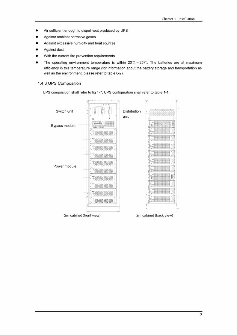
Chapter 1 Installation
9
Air sufficient enough to dispel heat produced by UPS
Against ambient corrosive gases
Against excessive humidity and heat sources
Against dust
With the current fire prevention requirements
The operating environment temperature is within 20~25 The batteries are at maximum
efficiency in this temperature range (for information about the battery storage and transportation as
well as the environment please refer to table 6-2)
143 UPS Composition
UPS composition shall refer to fig 1-7 UPS configuration shall refer to table 1-1
功率模块
旁路模块
开关单元 配电单元
2m cabinet (front view) 2m cabinet (back view)
Bypass module
Power module
Distribution
unit
Switch unit
Chapter 1 Installation
10
开关单元
旁路模块
功率模块
配电单元
16m cabinet (front view) 16m cabinet (back view)
Fig 1-7 UPS Composition Diagram
Table 1-1 UPS Configuration Table
Involved part name Quantity (Piece) Note
Cabinet
Switch PDU 1 Standard configuration
Monitoring + bypass
module 1 Standard configuration
Power module Power module 1~6 or 1~10
Field installation is
required
144 Operation Space
As UPS has no ventilation grills at either sides no clearances are required for the sides
To enable routine tightening of power terminations within the cabinet it is recommended that
clearance around the front and back of the equipment should be sufficient to enable free passage of
personnel with the doors fully opened
145 Front and Back Access
The component layout of the UPS supports front and back access for servicing diagnosing and
repairing the UPS thus reducing the space requirement for side access
146 Final Positioning
When the equipment has been finally positioned ensure the adjustable feet are set so that the UPS
will remain stationary and stable
147 Power Module Installation
The installation position of power module and output distribution module are shown in fig 1-8 the
installation principle of these module is to installed from bottom to top to prevent inclination of the cabinet
due to high center of gravity
As is shown in fig 1-8 the installation procedure of power module is as follows
Switch unit
Bypass module
Power module
Distribution unit
Chapter 1 Installation
11
1 Each module shall be installed from bottom to top the default setting of the system is module No 1
2 3 4 5 6 7 8 9 and 10
2 Insert the module into installation position and push in the cabinet The wiring terminals in between
shall be tight and excessive force shall be prevented against the damage to inserted pins of the
terminals
3 Fix the module to the cabinet though the mounting holes on two sides of the front plate of the
module
固定孔
A处放大
Fig 1-8 Power Module Installation Diagram
148 Cable Entry
Cables can enter the UPS from top and below as shown in fig 1-9 Both the top and bottom of the
UPS have cable entrance
The recommended installation practice is to install power cables in the entrance channel
at both sides of the cabinet back door so as not to affect the ventilation
进线通道 进线通道
Fig 1-9 Cable Entry Diagram
Power module
Fixing hole
Amplification of A
Cable entrance Cable entrance
Chapter 1 Installation
12
15 Protective Devices
For safety concerns it is recommended to install external circuit breakers or other protective devices
for the input AC supply of the UPS system This section provides generic practical information for
qualified installation engineers The installation engineers should have the knowledge of the regulatory
wiring standards and of the equipment to be installed
151 Rectifier and Bypass Input Supply of the UPS
Install suitable protective devices in the distribution unit of the incoming mains supply considering
the power cable current-carrying capacity and overload capacity of the system (see Table 1)Generally
the magnetic circuit breaker with IEC60947-2 tripping curve C (normal) at the 125 of the current listed
in table 1-1 is recommended
Note
For IT power network system 4-pole protective device must be installed on the external input
distribution of the UPS
If protection against earth faults (RCD devices) is required for the upstream of the input supply the
installed device should
Sensitive to DC unidirectional pulses (class A) in the network
Insensitive to transient current pulses
Have an average sensitivity that is adjustable between 03A~1A
The RCCB must be sensitive to DC unidirectional pulses (class A) in the network while insensitive
to transient current pulses as shown in fig 1-10 respectively
Fig 1-10 RCCB sign
152 Battery
A battery unit is composed of 40 batteries connected in series a centreline is drawn from in
between (the joint part between the 20th and 21st battery) plus the line drawn from the front and back
there are altogether 3 lines connected with UPS line contact bank The battery line must push through a
DC circuit breaker before connecting to corresponding UPS line contact bank The detailed wiring please
refer to fig 1-11 below
Fig 1-11 Diagram of batteries connected in series
40 batteries connected in series
Chapter 1 Installation
13
153 UPS Output
A main output switch has been installed in UPS the user shall install the over current protective
device on the bypass of each output of the external distribution cabinet
16 Power Cables
Design the cables according to the descriptions in this section and local regulatory wiring standards
and the environmental conditions should be taken into consideration Refer to IEC60950-1 Table 3B
Warning
Prior to cabling the UPS confirm the status and positions of the switches of the UPS rectifier input
power supply bypass power supply and mains power distribution board
Ensure that these switches are opened and attached with WARNING label so as to prevent
unauthorized operation to these switches
161 Maximum stable state current and configuration of cable system please refer to
table 1-2
Table 1-2 Maximum stable state current and configuration of cable system
System Name MD-06010 MD-09015 MD-12020 MD-10010 MD-15015 MD-20020
Capacity
System
capacity 60kVA 90kVA 120kVA 100kVA 150kVA 200kVA
Module
capacity 10kVA 15kVA 20kVA 10kVA 15kVA 20kVA
Cabinet
dimension 6009001600(WDH mm) 6009002000(WDH mm)
Main
Input
Rated
current A 90 136 180 150 227 300
Cable mm2 25 35 50 50 75 75
Output
Rated
current A 90 136 180 150 227 300
Cable mm2 25 35 50 50 75 75
Battery
Rated
current A 106 160 212 178 265 355
Cable mm2 35 50 75 50 75 90
PE Cable mm2 35 50 75 50 75 90
Warning
FAILURE TO FOLLOW ADEQUATE EARTHING PROCEDURES CAN RESULT IN EMI ELECTRIC
SHOCK HAZARD OR RISK OF FIRE
Chapter 1 Installation
14
162 Cable Connection
Note
The operations described in this section must be performed by authorized electricians or qualified
technical personnel If you have any difficulties do not hesitate to contact our Customer Service amp
Support department at the address given at the beginning of this manual
After the equipment has been finally positioned and secured connect the power cables as
described in the following procedures
1 Verify that all the external input distribution switches of the UPS are completely opened and the
UPS internal maintenance bypass switch is opened Attach necessary warning signs to these
switches to prevent unauthorized operation
2 Open the back door of the cabinet remove the cover and then the input and output terminal
battery terminal and earth terminal are visible
3 Connect the input earth wire to input earth terminal Please note the earth wire shall be connected
in accordance with related local or state regulation
4 For common bypass and rectifier inputs connect the AC input supply cables to the UPS input
terminals (Main input A-B-C-N) and connect the output loaded cable to the UPS output terminals
(Output A-B-C-N) and tighten the connections to 13 Nm (M8 Bolt) ENSURE CORRECT PHASE
ROTATION
5 Connect the battery cables between the UPS battery terminals and battery switch ENSURE
CORRECT PHASE ROTATION
Warning-Hazardous battery terminal voltage of 400Vdc
Ensure the correct polarity connection between the battery terminals and the UPS terminals Positive
terminal to positive terminal negative terminal to negative terminal and disconnect one or more than
one cable between every two layers of batteries Do not connect the cables and close the battery
circuit breakers before getting the approval from the commissioning engineer
6 Re-install all the protective covers
17 Control and Communication Cabling
As shown in fig 1-12 the front panel of the bypass module will provide dry contact interface
(J2~J10) communication interface (RS232 485 and SNMP card interface) as well as LBS interface
干接点接口
SNMP卡接口
RS485接口
RS232接口LBS接口
Fig 1-12 Dry contact interface and communication interface
Dry contact
interface
SNMP card port
LBS port RS232 port
RS485 port
Chapter 1 Installation
15
The UPS accepts external signal from zero-voltage (dry) contacts connected through external dry
contact terminals produced and phoenix terminals that are in bypass module Through software
programming these signals become active when these contacts connect to +24V to ground)The cables
connected to DRY terminal must be separated from power cables Moreover these cables should be
double insulated with a typical 05 to 15 mm2
cross-section area for a maximum connection length
between 25 and 50 meters
171 Dry Contact Interface of Battery and Environmental Temperature Detection
The input dry contact J2 and J3 can detect the temperature of batteries and environment
respectively which can be used in environment monitoring and battery temperature compensation 1
J2 and J3 interfaces diagram are shown in fig 1-13 the description of interface is in table 1-3
Fig 1-13 Diagram of J2 and J3 dry contact for temperature detecting
Table 1-3 Description of input dry contact interface J2 and J3
Position Name Purpose
J21 TEMP_BAT Battery temperature detection
J22 GND Power ground
J31 TEMP_ENV Environment temperature detection
J32 GND Power ground
Note Specified temperature sensor is required for temperature detection (R25=5Ohm
B2550=3275) please confirm with the manufacturer or contact local maintenance engineers when
placing an order
172 Remote EPO Input Port
The UPS has an Emergency Power OFF (EPO) function This function can be activated by pressing
a button on the control panel of the UPS or through a remote contact provided by the user The EPO
pushbutton is protected by a hinged plastic cover
J4 is the input port for remote EPO It requires shorting NC and +24v during normal operation and
the EPO is triggered when opening NC and +24v or shorting NO and +24v The port diagram is shown in
fig 1-14 and port description is shown in table 1-4
Chapter 1 Installation
16
Fig 1-14 Diagram of input port for remote EPO
Table 1-4 Description of input port for remote EPO
Position Name Purpose
J41 EPO_NC EPO is activated when disconnecting fromJ42
J42 +12V +24V connect the common terminal of NC and NO
J43 +12V EPO is activated when shorting with J42
The EPO is triggered when shorting pin 2 and 3 or opening pin 2 and 1 of J4
If an external emergency stop facility is required it is connected via the reserved terminals of J4
The external emergency stop facility needs to use shielded cables to connect to the normally
openclosed remote stop switch between these two pins If this facility is not used then pin 3 and pin 4 of
J4 must be open or pin 1 and pin 2 of J4 must be shorted
Note
1 The emergency stop action within the UPS will shut down the rectifier inverter and static bypass
However it does not internally disconnect the mains input power supply To disconnect ALL power to
the UPS open the upstream input circuit breaker(s) when the EPO is activated
2 Pin 1 and 2 of J4 have been shorted before the UPS is delivered
173 Generator Input Dry Contact
J5 is status interface for generator connection Connect pin 2 of J5 with + 24 power supply it
indicates that the generator has been connected with the system The interface diagram is shown in fig
1-15 and interface description is shown in table 1-5
Chapter 1 Installation
17
Fig 1-15 Diagram of status interface and connection of generator
Table 1-5 Description of maintenance bypass switch and output switch status interface
Position Name Purpose
J51 +24V +24V power supply
J52 GEN Connection status of generator
J53 GND Power ground
174 BCB Input Port
J6 and J7 are the ports of BCB The port diagram is shown in fig 1-16 and description is shown in
table 1-6
BC
B_D
RV
BC
B_C
ON
T
J6 J7
BC
B_O
NL
+24V+24V
+24V
Fig 1-16 BCB Port
Table 1-6 Description of BCB port
Position Name Description
J61 BCB_DRV BCB actuating signal provide the actuating signal of +18V 20mA
J62 BCB_CONT BCB contact status connect with the normally open signal of BCB
J71 GND Power ground
J72 BCB_ONL BCB on-linendashinput (normally open) BCB is on-line when the signal
is connecting with GND
175 Battery Warning Output Dry Contact Interface
J8 is the output dry contact interface which outputs the battery warnings of low or excessive
voltage when the battery voltage is lower than set value an auxiliary dry contact signal will be
provided via the isolation of a relay The interface diagram is shown in fig 1-17 and description is
shown in table 1-7
Generator
Chapter 1 Installation
18
Fig 1-17 Battery warning dry contact interface diagram
Table 1-7 Battery warning dry contact interface description Position Name Purpose
J81 BAT_LOW_NC Battery warning relay (normally closed) will be open during warning
J82 BAT_LOW_NO Battery warning relay (normally open) will be closed during warning
J83 GND Center of battery warning relay
176 Integrated Warning Output Dry Contact Interface
J9 is the integrated warning output dry contact interface when one or more than one preset
warning is triggered the system will send an integrated warning information and provide an auxiliary
dry contact signal via the isolation of a relay The interface diagram is shown in fig 1-18 and description
is shown in table 1-8
Fig 1-18 Integrated warning dry contact interface diagram
Table 1-8 Integrated warning dry contact interface description Position Name Purpose
J91 ALARM_NC Integrated warning relay (normally closed) will be open during warning
J92 ALARM_NO Integrated warning relay (normally open) will be closed during warning
J93 GND Centre of integrated warning relay
177 Mains Failure Warning Output Dry Contact Interface
J10 is the output dry contact interface for mains failure warning when the mains fails the system
will send a mains failure warning information and provide an auxiliary dry contact signal via the isolation
of a relay The interface diagram is shown in fig 1-19 and description is shown in table 1-9
Chapter 1 Installation
19
Fig 1-19 Mains failure warning dry contact interface diagram
Table 1-9 Mains failure warning dry contact interface description Position Name Purpose
J91 UTI_FAIL_NC Mains failure warning relay(normally closed) will be open during
warning
J92 UTI_FAIL_NO Mains failure warning relay normally open) will be closed during
warning
J93 GND Centre of mains failure warning relay
178 RS232 Port and SNMP Card Port
RS232 and RS485 Port provide serial data which can be used for commissioning and maintenance
by authorized engineers or maintainers or can be used for networking or integrated monitoring system in
the service room
SNMP Card Port used for field installation of the communication option card(SNMP card)
179 LBS (Load Bus Synchronizer) Port
The dual bus system (DBS) consists of two independent UPS rack module systems as shown in fig
1-20 The dual bus system is configured for high availability and is suitable for powering the load with
dual inputs If the load is single-input load the static transfer switch and LBS control is recommended to
maintain both UPS outputs synchronized for uninterrupted transfers Please install the system according
to the installation descriptions for different system configurations
The dual bus system is supported by UPS it requires connecting the LBS signal cables of two UPS
when constructing the dual bus system please refer to relevant chapter for detailed configuration and
installation and the system software shall be configured as required
UPS 1
LBS
监控旁路模块 UPS 2
LBS
监控旁路模块
Fig 1-20 LBS Connection Diagram
18 Installation Drawing
Please refer to fig 1-21 fig 1-22 fig 1-23 and fig 1-24
UPS 1 monitoring bypass module
UPS 2 monitoring bypass module
Chapter 1 Installation
20
Fig 1-21 Installation Diagram
Chapter 1 Installation
21
顶视图
2m cabinet front view
16 m cabinet (front view)
Fig 1-22 UPS front view (Unit mm)
Top view
Chapter 1 Installation
22
A
2m cabinet
A
16m cabinet
Fig 1-23 UPS back view
Chapter 1 Installation
23
A
A处放大
Fig 1-24 UPS front view
Amplification of A
24 Chapter 2 Operations
24
Chapter 2 Operations
This chapter introduces the basic knowledge of UPS operations including working principle
operation mode battery management and protection
Warning Hazardous mains voltage andor battery voltage present(s)behind the protective cover
The components that can only be accessed by opening the protective cover with tools cannot be
operated by user
Only qualified service personnel are authorized to remove such covers
21 Introduction
UPS provides the critical load (such as communication and data processing equipment) with high
quality uninterruptible AC power The power from UPS is free from voltage and frequency variations and
disturbances (interruption and spike) experienced at the Mains AC input supply
This is achieved through high frequency double conversion power pulse width modulation (PWM)
associated with full digital signal processing control (DSP) which features high reliability and
convenience for use
211 Principle
As shown in fig 2-1 the AC input mains source is supplied at UPS input and converted into a DC
source This DC source feeds the Inverter that converts the DC source into a clean and input
independent AC source The battery powers the load through the inverter in case of an AC input mains
power failure The utility source can also power the load through the static bypass
When the UPS needs maintenance or repair the load can be transferred to maintenance bypass
without interruption and the power module and bypass module can be removed for maintenance
Chapter 2 Operations 25
25
Fig 2-1 System principle framework
212 Bypass Module
The circuit blocks labeled ldquobypass modulerdquo in fig 2-1 contain electronically controlled switching
circuits that enable the critical load to be connected to either the inverter output or to a bypass power
source via the static bypass line During normal system operation the load is connected to the inverter
but in the event of a UPS overload or inverter failure the load is automatically transferred to the static
bypass line
To provide a clean (no-break) load transfer between the inverter output and static bypass line the
inverter output and bypass supply must be fully synchronized during normal operating conditions This is
achieved through the inverter control electronics which makes the inverter frequency track that of the
static bypass supply provided that the bypass remains within an acceptable frequency window
A manually controlled maintenance bypass supply is incorporated into the UPS design It enables
the critical load to be powered from the utility (bypass) supply while the UPS is shut down for routine
maintenance
Note
When the UPS is operating in bypass mode or on maintenance bypass the connected equipment is
not protected from power failures or surges and sags
22 Operation Mode
The MD UPS is an on-line double-conversion reverse-transfer UPS that permits operation in these
modes
Normal mode
26 Chapter 2 Operations
26
Battery mode
Auto-Restart mode
Bypass mode
Maintenance mode (manual bypass)
ECO mode
Frequency converters mode
221 Normal Mode
The UPS inverter power modules continuously supplies the critical AC load The rectifiercharger
derives power from the AC mains input source and supplies DC power to the inverter while
simultaneously FLOAT or BOOST charging its associated backup battery
222 Battery Mode
Upon failure of the AC mains input power the inverter power modules which obtains power from the
battery supplies the critical AC load There is no interruption in power to the critical load upon failure
After restoration of the AC mains input power the ldquoNormal Moderdquo operation will continue automatically
without the necessity of user intervention
Note UPS can also be started through battery (charged) mode via battery cold start function upon
failure of the AC mains Therefore the battery power can be used independently to improve the
utilization rate of UPS
223 Auto-Restart Mode
The battery may become exhausted following an extended AC mains failure The inverter shuts
down when the battery reaches the End of Discharge voltage (EOD) The UPS may be programmed to
ldquoAuto Recovery after EODrdquo after a delay time if the AC mains recovers This mode and any delay time
are programmed by the commissioning engineer
During the process of delay time the battery will be charged by UPS to prevent any risks to load
equipment from future mains failure
224 Bypass Mode
If the inverter overload capacity is exceeded under normal mode or if the inverter becomes
unavailable for any reason the static transfer switch will perform a transfer of the load from the inverter
to the bypass source with no interruption in power to the critical AC load
225 Maintenance Mode
A manual bypass switch is available to ensure continuity of supply to the critical load when the UPS
becomes unavailable eg during a maintenance procedure
Note This manual bypass switch is fitted in all UPS modules Transfer UPS system to bypass
module for power supply first then close maintenance bypass switch Q2 followed by Q1 and Q3
Warning hazard may occur after transferring to maintenance bypass
After UPS being transferred to maintenance bypass power module and bypass module do not work
no display on LCD and input and output terminals as well as N bus are electrically connected
Chapter 2 Operations 27
27
226 ECO Mode
If economical (ECO) mode is selected the double-conversion UPS will stop to work so as to save
energy During the operation of ECO mode the load power will be supplied by bypass preferentially
When bypass power is within the range of normal frequency and voltage load power will be supplied by
bypass or the system will transfer to inverter input followed by load power interruption which extends
within 34 of the utility period Eg when the frequency is 50Hz the interruption time will be less than
15ms when the frequency is 60Hz the time will be less than 125ms
227 Frequency Converters Mode
If the frequency converter configuration is used by UPS it will provide 50Hz or 60Hz stable output
frequency The range of output frequency is 40Hz~70Hz Under this mode static bypass is unavailable
but battery can be selected according to the actual requirements of battery mode
23 Battery Management
231 Normal Function
The following functions should be fitted by commissioning engineers with specified software
1 Constant current boost charging
Current can be set up
2 Constant voltage boost charging
Voltage of boost charging can be set as required by the type of battery
For Valve Regulated Lead Acid (VRLA) batteries maximum boost charge voltage should not
exceed 24V cell
3 Float charge
Voltage of float charging can be set as required by the type of battery
For VRLA float charge voltage should be between 22V to 23V
4 Float charge temperature compensation (optional)
A coefficient of temperature compensation can be set as required by the type of battery
5 End of discharge (EOD) protection
If the battery voltage is lower than the EOD the battery converter will shut down and the battery is
isolated to avoid further battery discharge EOD is adjustable from 16V to 175V per cell (VRLA) or 09
to 11 V per cell
6 Battery low warning time
It is adjustable between 3 and 60 minutes The default is 5 minutes
232 Advanced Functions (Battery Self-checking and Maintenance)
At periodic intervals 20 of the rated capacity of the battery will be discharged automatically and
the actual load must exceed 20 of the rated UPS (KVA) capacity If the load is less than 20
auto-discharge cannot be executed The periodic interval can be set from 30 to 360 days The battery
self-test can be disabled
ConditionsmdashBattery at float charge for at least 5 hours load equal to 20~100 of rated UPS capacity
TriggermdashManually through the command of ldquoBattery Maintenance Testrdquo in LCD panel or automatically
Battery Self-Test Intervalmdash30-360 days (default setting is battery self-test disabled)
28 Chapter 2 Operations
28
24 Battery Protection
The following functions should be fitted by commissioning engineers with specified software
1 Battery Low Pre-warning
The battery under voltage pre-warning occurs before the end of discharge After this pre-warning
the battery should have the capacity for 3 remaining minutes discharging with full load The time is user
configured from 3 to 60 minutes
2 Battery discharge (EOD)off protection
If the battery voltage is lower than the EOD the battery converter will be shut down EOD is
adjustable from 16V to 175V per cell (VRLA) or 09 to 11 V per cell (NiCd)
3 Battery Circuit Breaker (BCB) Alarm
The alarm occurs when the battery disconnect device disconnects The external battery connects to
the UPS through the external battery circuit breaker The circuit breaker is manually closed and tripped
by the UPS control circuit
Chapter 3 Operation Instructions 29
29
Chapter 3 Operating Steps
This chapter describes UPS operation instructions in detail
All functional keys and LED display involved in operation instructions please refer to chapter 4
During operation the buzzer alarm may occur at any time Select ldquomuterdquo on LED to muffle the audible
alarm
Warning-Hazardous mains voltage andor battery voltage present(s)behind the protective cover
1 The components that can only be accessed by opening the protective cover with tools cannot be
operated by user
2 Only qualified service personnel are authorized to remove such covers
31 Power Switches
As shown in fig 3-1 open the front door of UPS the power switch is visible which includes input
switch output switch and maintenance bypass switch (with anti-misoperation stop plate)
输入开关 输出开关
维修旁路开关
Fig 3-1 Power switch location diagram
32 UPS Start-up
The UPS system only has a maintenance bypass isolating switch and all the other transfers are
processed automatically by internal control logics
Input switch Output switch
Maintenance bypass switch
30 Chapter 3 Operating Instructions
30
321 Normal Module Start
This procedure must be followed when turning on the UPS from a fully powered down condition
The operating procedures are as follows
Warning
This procedure results in mains voltage being applied to the UPS output terminals If any load
equipment is connected to the UPS output terminals please check with the load user that it is safe to
apply power If the load is not ready to receive power then ensure that it is safely to close the output
switch of external distribution cabinet
1 Close UPS output switch and input switch in turns
The LCD starts up at this time The Rectifier indicator flashes during the startup of rectifier The
rectifier enters normal operation state and after about 30s the rectifier indicator goes steady green After
initialization the bypass static switch closes The UPS Mimic LEDs will indicate as shown in table 3-1
Table 3-1 Indicator status
LED Status
Rectifier indicator Green
Battery indicator Red
Bypass indicator Green
Inverter indicator Off
Load indicator Green
Status indicator Green
Note
The output circuit breaker must be closed first followed by input circuit breaker or the rectifier cannot
be started and alarm ldquorectifier failurerdquo
The inverter starts up at this time the inverter indicator flashes After the rectifier enters normal
operation state UPS power supply will transfer from bypass to inverter then the bypass indicator turns
off and load indicator lights The status of indicators is shown in table 3-2
Table 3-2 Indicator Status
LED Status
Rectifier indicator Green
Battery indicator Red
Bypass indicator Off
Inverter indicator Green
Load indicator Green
Status indicator Green
Close external battery switch again battery indicator turns off a few minutes later the battery will be
charged by UPS which will enter normal mode operation The indicator status is shown in table 3-3
Table 3-3 Indicator status
LED Status
Rectifier indicator Green
Battery indicator Green
Bypass indicator Off
Inverter indicator Green
Load indicator Green
Status indicator Green
322 Operating steps of Battery cold Start
1 Check if the batteries have been connected close the external battery switch
Chapter 3 Operation Instructions 31
31
2 Press the red start-up button of battery under the rectifier input circuit breaker for 3 seconds (see fig
3-2)
The LCD starts up at this time The green battery indicator flashes The rectifier enters normal
operation states and after about 30s the battery indicator goes steady green
3 The inverter starts up automatically the green inverter indicator flashes The output of inverter
appears after 60s The UPS works on battery mode
32 Chapter 3 Operating Instructions
32
电池启动按钮
Fig 3-2 Position diagram of battery startup button
Battery startup button
Chapter 3 Operation Instructions 33
33
33 Procedure for Switching between Operation Modes
331 Procedure for Switching the UPS into Battery mode from Normal Mode
Open input switch to cut off the mains UPS enters the battery mode If UPS should be switched to
normal mode wait for a few seconds before close input switch so as to supply the mains again 10s
later the rectifier will start up automatically to supply power to the inverter
332 Procedure for Switching the UPS into Bypass mode from Normal Mode
Select ldquoTran Byprdquo on the LCD or press ldquooffrdquo buttons of each power module in turn
Note
In bypass mode the load is directly fed by the mains power instead of the pure AC power from the
inverter
333 Procedure for Switching the UPS into Normal from Bypass Mode
Select exit bypass mode on the LCD
334 Procedure for Switching the UPS into a Maintenance Bypass from Normal Mode
In normal operation this operation instruction will switch the load from inverter input to maintenance
bypass
Caution
Before making this operation read messages on display to be sure that bypass supply is regular and
the inverter is synchronous with it so as not to have a risk of a short interruption in powering the load
1 Press ldquoTran Byprdquo on the LCD or press ldquooffrdquo on each power module in turns
If press rdquoTran Byprdquo on the LCD the inverter indicator will flash green and the buzzer will alarm
If press ldquooffrdquo on each power module in turns the inverter indicator will go off and the buzzer will
alarm
The load will be transferred to static bypass and the inverter is closed
2 Close maintenance bypass switch Q2 the load power will be supplied by maintenance bypass and
then open the inverter circuit breaker Q1 output switch Q3 and battery switch
Warning
If you need to maintain the module wait for 10 minutes to let the DC bus capacitor fully discharge
before removing corresponding module
335 Procedure for Switching the UPS into Normal from a Maintenance Bypass Mode
This procedure can transfer the load to normal main mode when the UPS is operating under the
maintenance bypass mode
1 Close output switch Q3 and main switch Q1
The bypass indicator goes green and the load power will be supplied by bypass and maintenance
bypass
2 Open maintenance bypass switch Q2
34 Chapter 3 Operating Instructions
34
The load power is supplied by bypass In the meantime the rectifier starts up rectifier indicator goes
green 30s later at this time the inverter will start up automatically and transfer to inverter mode 1 min
later automatically
3 Close external battery switch the battery indicator goes off Check if the battery voltage on LCD
display is normal
34 Procedure for Completely Powering down a UPS
If you need to power down the UPS completely follow the procedures in section 334 to transfer the
UPS from normal mode to maintenance bypass mode
If you need to isolate the UPS from the AC power supply you should open the external input switch
35 EPO Procedure
The EPO button on UPS operator control and display panel is designed to switch off the UPS in
emergency conditions (eg fire flood etc)To achieve this just press the EPO button and the system
will turn off the rectifier inverter and stop powering the load immediately (including the inverter and
bypass output) and the battery stops charging or discharging
If the input utility is present the UPS control circuit will remain active however the output will be
turned off To completely isolate the UPS you need to open the external mains input supply to the UPS
rack
36 Language Selection
The LCD is available in two languages Chinese English and Korean
The language can be selected through LCD prompt window
37 Control Password
When the LCD displays ldquoinput control password 1rdquo the initial password is 12345678
Chapter 4 Operator Control and Display Panel 35
35
Chapter 4 Operator Control and Display Panel
This chapter introduces the functions and operation instructions of the parts on UPS operator control
and display panel in detail and provides LCD display information including LCD display types detailed
menu information prompt window information and UPS alarm list
41 Introduction
The operator control and display panel is located on the front panel of the UPS Through this LCD
panel the operator can operate and control the UPS and check all measured parameters UPS and
battery status and event and alarm logs The operator control panel is divided into three functional areas
as shown in fig 4-1 mimic current path LCD display amp Menu keys and Control and Operation Keys The
detailed description of parts on operator control and display panel is shown in table 4-1
Fig 4-1 UPS operator control and display panel
Table 4-1 Description of UPS operator control and display panel
Part No Function Button Function
REC Rectifier indicator EPO EPO switch
BAT Battery indicator TAB switch
BYP Bypass indicator ENTER confirm
INV Inverter indicator ESC exit
OUTPUT Load indicator
STATUS Status indicator
36 Chapter 4 Operator Control and Display Panel
36
411 LED Indicator
The LEDs shown on the mini current path represent the various UPS power paths and show the
current UPS operating status The status description of indicators is shown in table 4-2
Table 4-2 Status description of indicator
Indicator State Purpose
Rectifier
indicator
Steady green Rectifier normal for all modules
Flashing green Rectifier for at least on module normal mains normal
Steady red Rectifier fault
Flashing red Mains abnormal for at least one module
Off Rectifier not operating
Battery
indicator
Steady green Battery charging
Flashing green Battery discharging
Steady red
Battery abnormal (battery failure no battery or battery reverse) or
battery converter abnormal (failure over current or over temperature)
EOD
Flashing red Battery low voltage
Off Battery and battery converter normal battery not charging
Bypass
indicator
Steady green Load power supplied by bypass
Steady red Bypass power abnormal or out of normal range or static bypass
switch fault
Flashing red Bypass voltage abnormal
Off Bypass normal
Inverter
indicator
Steady green Load power supplied by inverter
Flashing green Inverter On start synchronization of standby (ECO mode) for at least
one module
Steady red System power not supplied by inverter inverter fault for at least one
module
Flashing red System power supplied by inverter inverter fault for at least one
module
Off Inverter not operating for all modules
Load
indicator
Steady green UPS output ON and normal
Steady red UPS output overload and overtime or output short or output no power
supply
Flashing red Overload output of UPS
Off No output of UPS
Status
indicator
Steady green Normal operation
Steady red Failure
412 Audible Alarm (buzzer)
There are two different types of audible alarm during UPS operation as shown in table 4-3
Table 4-3 description of audible alarm
Alarm Purpose
Two short alarm with
a long one
when system has general alarm (for example AC fault) this audible alarm
can be heard
Continuous alarm When system has serious faults (for example fuse or hardware fault) this
audible alarm can be heard
Chapter 4 Operator Control and Display Panel 37
37
413 Functional Keys
There are 4 functional keys on operator control and display panel which are used together with LCD
The functions description is shown in table 4-4
Table 4-4 Functions of functional keys
Functional key Functions
EPO switch To cut off the load power to shut down the rectifier inverter static
bypass and battery
TAB switch
ENTER confirm
ESC exit
42 LCD Display Type
Following the self-check of UPS LCD display the main LCD display is shown as fig 4-2 which can
be divided into three display windows system information data command and current record
Fig 4-2 Main LCD display
The description of LCD icon is shown in table 4-5
Table 4-5 Description of LCD icons
Icon Description
Bypass parameter
UPS system
information
window
Data
command
window
Current
record
window
38 Chapter 4 Operator Control and Display Panel
38
Icon Description
Main input parameter
History file system information
Function setting (display calibration password setting time setting date format
communication protocol and language setting) system setting (used by product
maintainers)
Battery data battery parameter setting (used by service staff)
Test (battery self-test battery maintenance)
Functional keys used by service staff (fault clearing history file clearing noise
clearing manual switch of bypass) userrsquos setting (system mode machine
number system ID output voltage adjustment frequency tracing speed
frequency tracing limit)
Output parameter
Load
Noise clearing noise clearing cancel
Log view page updown
Select a icon on LCD as shown in fig 4-3 to view the UPS parameter represented by this icon eg
select the LCD will display the data of system main input
Chapter 4 Operator Control and Display Panel 39
39
Fig 4-3 Select data
Or select and confirm a module as shown in fig 4-4 the LCD will display the
operating status of this module
Fig 4-4 Select a module
40 Chapter 4 Operator Control and Display Panel
40
Select in the operating status of a module to view the main input data of this module
Select in the operating status of a module to view the main output data of this module
Select in the operating status of a module to view the load data of this module
Select in the operating status of a module to view the maintenance code and module
software code of this module
Select to return to the previous page
Select to return to the home page
Default display
During the operation of system if therersquos no alarm in 2 min the system will display default After a
short delay the backlight of LCD display goes off press any key to reactivate the display
43 Detailed Description of Menu Items
The LCD main display shown in fig 4-2 is described in details below
UPS information window
UPS information window display the current time and UPS name The information of the window is
not necessary for the user to operate The information of this window is given in table 4-6
Table 4-6 Description of items in UPS system information window
Display contents Meaning
MD12020 UPS Name
1200 Current Time (format 24 hours hours minute)
UPS menu and data window
UPS menu window displays the menu name of data window while the data window displays the
related contents of selected menu in menu window Select UPS menu and data window to browse
related parameters of UPS and set related functions The details are given in table 4-7
Table 4-7 Item description of UPS menu and data window
Menu name Menu item Meaning
Main input
V phase(V) V phase
I phase(A) I phase
Freq(Hz) Input frequency
PF Power factor
Bypass input
V phase(V) V phase
Freq (Hz) Bypass frequency
I phase(A) I phase
PF Power factor
AC output
V phase(V) V phase
I phase(A) I phase
Freq (Hz) Output frequency
PF Power factor
This UPS Sout (kVA) Sout Apparent Power
Chapter 4 Operator Control and Display Panel 41
41
Menu name Menu item Meaning
modulersquos
load
Pout (kW) Pout Active Power
Qout (kVAR) Qout Reactive Power
Load () Load (The percentage of the UPS rating load)
Battery data
Environmental
Temp Environmental Temp
Battery
voltage(V) Battery bus voltage
Battery current
A) Battery bus current
Battery
Temp() Battery Temp
Remaining Time
(Min) Remaining battery backup time
Battery capacity
() The percentage compared with new battery capacity
battery
equalized
charging
Battery is equalized charging
battery float
charging Battery is float charging
Battery
disconnected Battery is not connected
Current
record (current alarm)
Display all current alarm The alarm list displayed on LCD of
UPS operator control and display panel please refer to table 4-9
History
record (history alarm)
Display all history alarm The alarm list displayed on LCD of
UPS operator control and display panel please refer to table 4-9
Menu
Language
(language
option) 2 languages can be selected
Settings
Display
calibration Adjust the accuracy of LCD display
Date format set MM DD YYYY and YYYY MM DD formats can be selected
Date amp Time DateTime set
Language set User can set the language (Chinese and English)
Communication
mode
Set communication mode MODBUS Power protocol and
company custom protocol modes can be selected Power
protocol mode can be divided into equipment address baud
rate set MODBUS protocol mode can be divided into
communication mode (RTUASCⅡ) equipment address
baud rate and check-bit set Company custom protocol mode
is the customed protocol of the company no option is
available
Control
password set User can modify control password 1
Test
Command
(Battery Test
Control
Battery
maintenance
test
This test will lead to the battery being partly discharged to
activate battery at the same time the approximate battery
capacity will be obtained Bypass must be in normal condition
the battery capacity should be above 25
42 Chapter 4 Operator Control and Display Panel
42
Menu name Menu item Meaning
Battery
self-check test
UPS switches to battery discharge for discharging to test if the
battery is normal Bypass must be in normal condition the
battery capacity should be above 25
Stop testing Manually Stop the test including maintenance test capacity test
UPS system
information
Monitoring
software version Provide monitoring software version
Rectified
software version Provide rectified software version
Inverted
software version Provide inverted software version
Serial No The serial no set when delivery from the factory
Rated
information Network setting of system operating
Module type Type of the module
44 Alarm List
The follow table 4-8 gives the complete list of all the UPS events displayed by history record window
and current record window
Table 4-8 Alarm List
Alarm Explanation
UPS power supply The system is in normal inverted power supply status
Bypass power
supply The system is in bypass power supply status
No power supply System no output
Battery equalized
charging Battery is in boost charging
Battery float
charging Battery is in float charging
Battery discharging The system is operating in battery discharging status
Battery connected Battery is connected
Battery
disconnected Battery is not connected
Maintenance circuit
breaker close Maintenance circuit breaker is close
Maintenance circuit
breaker open Maintenance circuit breaker is open
Emergency
shutdown System emergency shutdownEPO
Generator
connected External generator is connected
Mains abnormal Input mains abnormal
Bypass phase
conversion Bypass input phase converse
Bypass voltage
abnormal Bypass input voltage abnormal
Bypass fault Bypass fault
Bypass overload Bypass output is overload
Up to bypass
overtime of Bypass is overtime of overload
Chapter 4 Operator Control and Display Panel 43
43
Alarm Explanation
overload
Bypass frequency
tracing exceeds Bypass frequency is out of the tracing range
Switch times up to
in this hour
The times of switch between bypass and inverter exceeds 5 times in the latest
hour
Output short System output short
Battery EOD Battery voltage achieves shutdown point
Battery self-check The system enters battery self-check mode
Battery self-check
success Battery normal during system self-check
Battery manual
check failure Battery fault during system self-check
Battery
maintenance The system is in battery maintenance status
Battery
maintenance
success
Battery maintenance status completes
Battery
maintenance failure Battery maintenance process is not normal
Stop testing Battery self-check or battery maintenance status stops
Fault clearing Clear the alarmed fault
Delete history
record Delete all history record
N communication
node connected N module is connected to UPS system
N communication
node disconnected N module is not connected to UPS system
N rectifier fault N module rectifier fault
N inverter fault N module inverter fault
N rectifier
overheat N module rectifier overheat
N fan fault N module fan fault
N output overload N module output overload
N overtime of
overload N module output overtime of overload
N inverter
overheat N module inverter overheat
Inverter power
supply ban Inverter power ban supply
Manual switch of
bypass Switch the system to bypass output manually
Cancel manual
switch of bypass Switch the system from bypass to inverter output manually
Battery low voltage Battery low voltage
Battery reversal Battery polarity reversal
N inverter
protection N module inverter protection
Input N line
disconnected System input N line is not connected
Bypass fan fault Bypass module fan fault
N manual N module manual power off
44 Chapter 4 Operator Control and Display Panel
44
Alarm Explanation
shutdown
Chapter 5 Maintenance 45
45
Chapter 5 Installation of Parallel Operation System
The parallel operation system is installed as required by the installation procedures of the single
system and this chapter
The single devices are put parallel and connected as shown in fig 5-1 and the difference between
the lengths of the output cables of the single devices is not more than 10m It is recommended to use an
external bypass cabinet to facilitate maintenance and system testing
Fig 5-1 Typical 1+N parallel operation system
Note when the load exceeds is the capacity of the single device the maintenance bypass
switch CB3 must be removed
The cables for the parallel operation provide double insulation shielding up to 30m long the control
cables for the parallel operation must be connected with all single devices to form a closed loop as
shown in fig5-2
Other power supplies
Rectifier
Charger Inverter Inverter
Output power supply
Load connected
Mains power input L1 L2 L3 N terminal
Mains power inputL1 L2 L3 N terminal
Rectifier
Charger
46 Chapter 5 Maintenance
46
Fig5-2 parallel cables
Chapter 5 Maintenance 47
47
Chapter 6 Maintenance
This chapter introduces UPS maintenance including the maintenance instructions of power module
monitoring bypass module and the change method of dust filter
61 Instruction to Power Bypass and Output Power Distribution
Module
611 Precautions
1 Only maintaining engineers can maintain the power module and monitoring bypass module
2 In principle the power module and bypass module should be disassembled from top to bottom so
as to prevent any inclination from high gravity centre of the cabinet
3 To ensure the safety before maintaining power module and bypass module be sure to use a
multimeter to measure the DC bus capacitor voltage and ensure the voltage is below 60V before
operation and use a multimeter to measure the voltage between operating parts and the earth to
ensure the voltage is lower than hazardous voltage ie DC voltage is lower than 60Vdc and AC
maximum Voltage is lower than 424Vac
4 Bypass module doesnrsquot support any hot insertion and extraction only when UPS is in maintenance
bypass mode or UPS is completely power off can the bypass module be disassembled
5 The module can be maintained 10 mins after extracting power module and bypass module which
can be inserted into the cabinet 10 mins later
612 Instruction to Power Module
Suppose UPS were in normal mode and bypass were normal a module shall be maintained at
first
1 Press OFF of the module with a pin point or other tiny matter the module will shut down
automatically and exit the system
Note ensure if the remaining module will be overload when exiting a module If therersquos any risk of
overload transfer the whole UPS system to bypass followed by other operations
2 Take off the fixing bolt on the two sides of front and back plate of power module 10 mins later
extract the module from the cabinet
3 After maintaining the module push the module into the equipment cabinet (the interval between
two modules shall be more than 10s) fix the screw on the two sides Then the module will be
connected to UPS system automatically
613 Instruction to Bypass Module
Suppose UPS were in normal mode and the bypass were normal
1 Select LCD touch screen manual switch of bypass the UPS power will be supplied by bypass
2 Close maintenance bypass switch the UPS power will be supplied by maintenance bypass
3 Open UPS output switch and input switch
4 Open external battery switch
48 Chapter 5 Maintenance
48
5 Take off the fixing bolt at the two sides of front board of bypass module extract the front cable
assembly of the module and extract the module from the cabinet
6 After maintaining the module insert the module into the cabinet tighten the screw at the two sides
and connect the front cable assembly of manufacturerrsquos module
7 Close UPS output switch and input switch in turn
2 mins later bypass indicator on the operator control and display panel lights on which indicates
the normal power supply of bypass
8 Open maintenance bypass switch the inverter starts automatically 60s later the UPS will transfer
to normal mode
62 Replacing Dust Screen (optional)
As shown in fig 5-1 there are 3~4 dust filters on the back of UPSrsquo front door each screen is held in
place by a bracket on either side of each filter The procedure of replacing each filter is as follows
1 Open the UPSrsquo front door and locate the filters on the back side of the front door
2 Remove one bracket
3 Remove the dust screen to be replaced and insert the clean one
4 Reinstall the bracket
防尘网固定条
Fig 5-1 Dust screen on the back side of UPS front door
Bracket
Dust screen
Appendix 2 Toxic or Hazardous Materials or Elements Identification Table 49
49
Chapter 7 Product Specification
This chapter provides UPS product specification
71 Applicable Standards
The UPS has been designed to conform to the following European and international standards
Table 6-1 Compliance with European and International Standards
Item Normative reference
General safety requirements for UPS
used in operator access areas EN50091-1-1IEC62040-1-1AS 62040-1-1
Electromagnetic compatibility (EMC)
requirements for UPS EN50091-2IEC62040-2AS 62040-2(C3)
Method of specifying the performance
and test requirements of UPS EN50091-3IEC62040-3AS 62040-3(VFI SS 111)
Note The above mentioned product standards incorporate relevant compliance clauses with generic
IEC and EN standards for safety (IECENAS60950) electromagnetic emission and immunity
(IECEN AS61000 series) and construction (IECENAS60146 series and 60950)
72 Environmental Characteristics
Table 6-2 Environmental Properties
Items Unit Requirements
Acoustic noise level at 1
meter dB 550
Altitude of Operation m le1000m above sea level derate power by 1 per 100m
between 1000m and 2000m
Relative Humidity RH 0 to 95 non condensing
Operating Temperature 0 to 40 deg Battery life is halved for every 10degC increase
above 20degC
UPS Storage-Transport
Temperature -20~70
Recommended Battery
Storage Temperature -20~30 (20degC for optimum battery storage)
73 Mechanical Characteristics
Table 6-3 Mechanical Properties
Cabinet Specification Unit MD6010 MD9015
MD12020
MD10010 MD15015
MD20020
Mechanical Dimension
WtimesDtimesH mm 600times900times1600 600times900times2000
Weight kg 151 182
Color NA Black
Protection Level
IEC(60529) NA IP20
50 Chapter 5 Maintenance
50
Module type Unit MU10 MU15 MU20
Mechanical Dimension
WtimesDtimesH mm 440times590times134
Weight kg 21 22 22
Color NA Black
74 Electrical Characteristics (Input Rectifier)
Table 6-4 Rectifier AC input (mains)
Items Unit Parameter
Rated AC Input
Voltage Vac
380400415(three-phase and sharing neutral with the
bypass input)
Input voltage range Vac -40~+25
Frequency2 Hz 5060(range 40Hz~70Hz)
Power factor kWkVA full load 099
THD THDI 3
75 Electrical Characteristics (Intermediate DC Link)
Table 6-5 Battery
Items Unit Parameters
Battery bus
voltage Vdc Nominal plusmn240V one-side range 198V~288V
Quantity of
lead-acid cells Nominal 40=[1 battery(12V) ] 240=[1 battery(2V) ]
Float charge
voltage Vcell(VRLA)
225Vcell(selectable from 22Vcell~235Vcell)
Constant current and constant voltage charge mode
Temperature
compensation mVcl -30(selectable from 0~-50 25 or 30 or inhibit)
Ripple voltage V float le1
Ripple current C10 le5
equalized
charge voltage VRLA
24Vcell(selectable from 230Vcell~245Vcell)
Constant current and constant voltage charge mode
final
discharging
voltage
Vcell(VRLA)
165Vcell(selectable from 160Vcell ~ 1750Vcell) 06C
discharge current
175Vcell (selectable from 165Vcell ~ 18Vcell) 015C
discharge current
(EOD voltage changes linearly within the set range according to
discharge current)
Battery Charge Vcell 24Vcell(selectable from 23Vcell~245Vcell)
Constant current and constant voltage charge mode
Battery
Charging Power
Max Current
kW 10 UPS capacity (selectable from 0~20 UPS capacity)
Appendix 2 Toxic or Hazardous Materials or Elements Identification Table 51
51
76 Electrical Characteristics (Inverter Output)
Table 6-6 Inverter Output (to important load)
Rated
capacity(kVA) Unit 10~200
Rated AC voltage1 Vac 380400415(three-phase four-wire and sharing neutral with the
bypass)
Freqency2 Hz 5060
overload
110 load 1 hour
125 load 10min
150 load 1min
>150 load 200ms
Fault current 340 short current limitation for 200ms
Non linear load
capability 3 100
Neutral current
capability 170
Steady state
voltage stability
plusmn1(balanced load)
plusmn15(100 imbalance load)
Transient voltage
response 4 plusmn5
THD <15(linear load) <5(non linear load3)
Synchronization -
Window Rated frequency plusmn2Hz(selectable plusmn1~plusmn5Hz)
Max change rate of
synch frequency Hzs 1 selectable 01~5
Inverter voltage
range V(ac) plusmn5
Note
1 Factory setting is 380V Commissioning engineers can set to 400V or 415V
2 Factory setting is 50Hz Commissioning engineers can set to 60Hz
3 EN50091-3(1458) peak value factor is 3 1
4 IEC62040-3EN50091-3 including 0~100~0 load transient the recovery time is half
circle to within 5 of stable output voltage
52 Chapter 5 Maintenance
52
77 Electrical Characteristics(Bypass Mains Input)
Table 6-7 Bypass Mains Input
Rated
capacity(kVA) Unit 60 90 100 120 150 200
Rated AC
Voltage1 Vac
380400415
three-phase four-wire sharing neutral with the rectifier input and providing neutral
reference for the output
Rated current A
91380V
87400V
83415V
136380V
130400V
124415V
151380V
144400V
138415V
182380V
174400V
166415V
227380V
216400V
207415V
302380V
288400V
276415V
Overload
125 load long term
130 load 1 hour
150 load 6min
1000 load 100ms
Superior
protection
bypass line
NA Thermal-magnetic breaker the capacity is 125 of rated current output
IEC60947-2 curve C
Current rating
of neutral cable A 17timesIn
Frequency2 Hz 5060
Switch time
(between
bypass and
inverter)
ms Synchronized switch le1ms
Bypass voltage
tolerance Vac
Upper limit +10+15or+20 default +20
Lower limit -10 -20 -30 or-40 default-20
(acceptable stable bypass voltage delay 10s)
Bypass
frequency
tolerance
plusmn25 plusmn5 plusmn10 or plusmn20 default plusmn10
Synchronizatio
n-Window Hz Rated frequencyplusmn2Hz (selectable from plusmn05Hz~plusmn5Hz)
Note
1 Factory setting is 400V Commissioning engineers can set to 380V or 415V
2 Factory setting is 50Hz Commissioning engineers can set to 60Hz For example UPS is set to frequency
inverter mode and then bypass status will be neglected
78 Efficiency
Table 6-8 Efficiency Loss and Air Exchange
Rated Efficiency (kVA) Unit 10~200kVA
Normal mode(dual conversion) 95
ECO mode 99
Battery discharging efficiency (DCAC) (battery at nominal voltage 480Vdc and full-rated linear load)
battery mode 95
Appendix 2 Toxic or Hazardous Materials or Elements Identification Table 53
53
Appendix A A Guidebook to Ordering and Selection of MU System
MD series UPS module can be divided into equipment cabinet and power module For the cabinet
lectotype please refer to the description in fig 6-1
Fig 6-1 Cabinet Selection
For single power module type please refers to the description in fig 6-2
Fig 6-2 Power Module Selection
Egg the requirements of a plant room are given below
The maximum power supply of the plant room is 120kVA however it is expected to be expanded to
200kVA in 3-5 years Therefore a 200kVA cabinet and 6 20kVA power module can be purchased to
constitute an uninterrupted 120kVA power system which can be expanded to 200kVA on-line The order
symbol is
1 set MD20020
6 set MU20
Option list
MD-SNMP card remote network monitoring card
MD-1600 dust filter dust screen for 16m cabinet
MD-2000 dust filter dust screen for 2m cabinet
Represents the capacity of a single power module
10 represents 10kVA
15 represents 15kVA
20 represents 20kVA
represents a single power module
Represents UPS system capacitypower module
06010 represents 60kVA10kVA
09015 represents 90kVA15kVA
12020 represents 120kVA20kVA
15015 represents 150kVA15kVA
20020 represents 200kVA20kVA
MD represents UPS cabinet
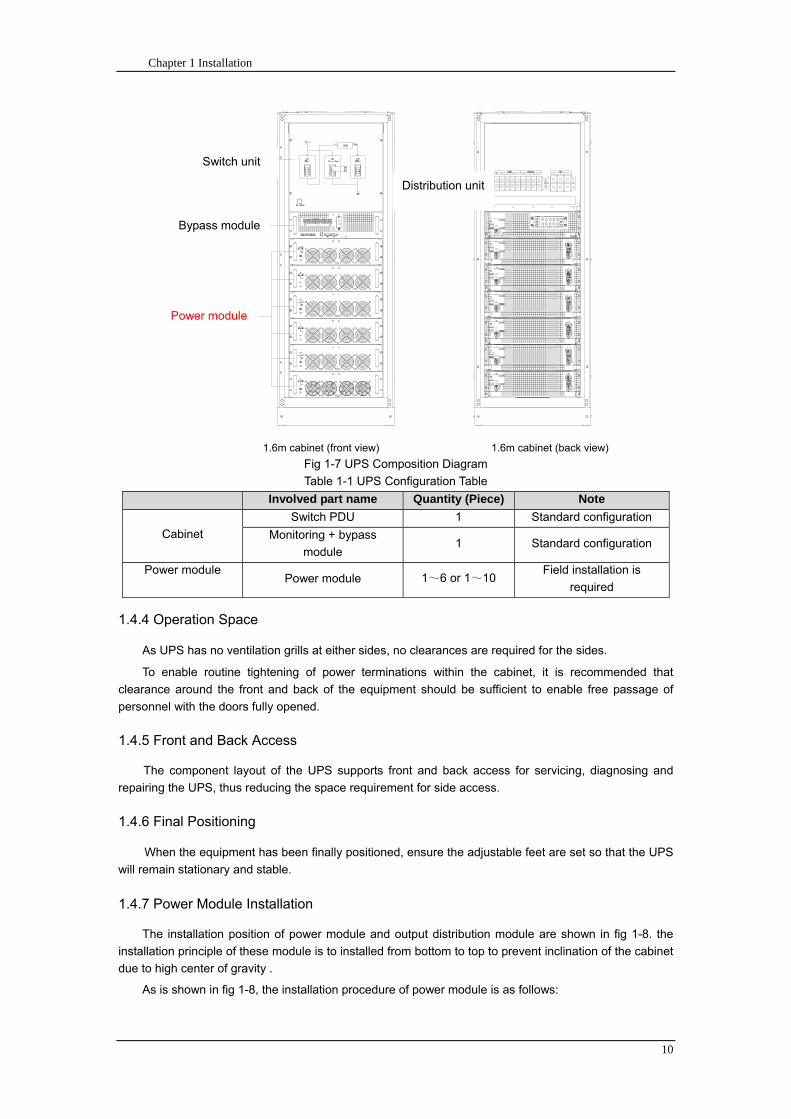
Chapter 1 Installation
10
开关单元
旁路模块
功率模块
配电单元
16m cabinet (front view) 16m cabinet (back view)
Fig 1-7 UPS Composition Diagram
Table 1-1 UPS Configuration Table
Involved part name Quantity (Piece) Note
Cabinet
Switch PDU 1 Standard configuration
Monitoring + bypass
module 1 Standard configuration
Power module Power module 1~6 or 1~10
Field installation is
required
144 Operation Space
As UPS has no ventilation grills at either sides no clearances are required for the sides
To enable routine tightening of power terminations within the cabinet it is recommended that
clearance around the front and back of the equipment should be sufficient to enable free passage of
personnel with the doors fully opened
145 Front and Back Access
The component layout of the UPS supports front and back access for servicing diagnosing and
repairing the UPS thus reducing the space requirement for side access
146 Final Positioning
When the equipment has been finally positioned ensure the adjustable feet are set so that the UPS
will remain stationary and stable
147 Power Module Installation
The installation position of power module and output distribution module are shown in fig 1-8 the
installation principle of these module is to installed from bottom to top to prevent inclination of the cabinet
due to high center of gravity
As is shown in fig 1-8 the installation procedure of power module is as follows
Switch unit
Bypass module
Power module
Distribution unit
Chapter 1 Installation
11
1 Each module shall be installed from bottom to top the default setting of the system is module No 1
2 3 4 5 6 7 8 9 and 10
2 Insert the module into installation position and push in the cabinet The wiring terminals in between
shall be tight and excessive force shall be prevented against the damage to inserted pins of the
terminals
3 Fix the module to the cabinet though the mounting holes on two sides of the front plate of the
module
固定孔
A处放大
Fig 1-8 Power Module Installation Diagram
148 Cable Entry
Cables can enter the UPS from top and below as shown in fig 1-9 Both the top and bottom of the
UPS have cable entrance
The recommended installation practice is to install power cables in the entrance channel
at both sides of the cabinet back door so as not to affect the ventilation
进线通道 进线通道
Fig 1-9 Cable Entry Diagram
Power module
Fixing hole
Amplification of A
Cable entrance Cable entrance
Chapter 1 Installation
12
15 Protective Devices
For safety concerns it is recommended to install external circuit breakers or other protective devices
for the input AC supply of the UPS system This section provides generic practical information for
qualified installation engineers The installation engineers should have the knowledge of the regulatory
wiring standards and of the equipment to be installed
151 Rectifier and Bypass Input Supply of the UPS
Install suitable protective devices in the distribution unit of the incoming mains supply considering
the power cable current-carrying capacity and overload capacity of the system (see Table 1)Generally
the magnetic circuit breaker with IEC60947-2 tripping curve C (normal) at the 125 of the current listed
in table 1-1 is recommended
Note
For IT power network system 4-pole protective device must be installed on the external input
distribution of the UPS
If protection against earth faults (RCD devices) is required for the upstream of the input supply the
installed device should
Sensitive to DC unidirectional pulses (class A) in the network
Insensitive to transient current pulses
Have an average sensitivity that is adjustable between 03A~1A
The RCCB must be sensitive to DC unidirectional pulses (class A) in the network while insensitive
to transient current pulses as shown in fig 1-10 respectively
Fig 1-10 RCCB sign
152 Battery
A battery unit is composed of 40 batteries connected in series a centreline is drawn from in
between (the joint part between the 20th and 21st battery) plus the line drawn from the front and back
there are altogether 3 lines connected with UPS line contact bank The battery line must push through a
DC circuit breaker before connecting to corresponding UPS line contact bank The detailed wiring please
refer to fig 1-11 below
Fig 1-11 Diagram of batteries connected in series
40 batteries connected in series
Chapter 1 Installation
13
153 UPS Output
A main output switch has been installed in UPS the user shall install the over current protective
device on the bypass of each output of the external distribution cabinet
16 Power Cables
Design the cables according to the descriptions in this section and local regulatory wiring standards
and the environmental conditions should be taken into consideration Refer to IEC60950-1 Table 3B
Warning
Prior to cabling the UPS confirm the status and positions of the switches of the UPS rectifier input
power supply bypass power supply and mains power distribution board
Ensure that these switches are opened and attached with WARNING label so as to prevent
unauthorized operation to these switches
161 Maximum stable state current and configuration of cable system please refer to
table 1-2
Table 1-2 Maximum stable state current and configuration of cable system
System Name MD-06010 MD-09015 MD-12020 MD-10010 MD-15015 MD-20020
Capacity
System
capacity 60kVA 90kVA 120kVA 100kVA 150kVA 200kVA
Module
capacity 10kVA 15kVA 20kVA 10kVA 15kVA 20kVA
Cabinet
dimension 6009001600(WDH mm) 6009002000(WDH mm)
Main
Input
Rated
current A 90 136 180 150 227 300
Cable mm2 25 35 50 50 75 75
Output
Rated
current A 90 136 180 150 227 300
Cable mm2 25 35 50 50 75 75
Battery
Rated
current A 106 160 212 178 265 355
Cable mm2 35 50 75 50 75 90
PE Cable mm2 35 50 75 50 75 90
Warning
FAILURE TO FOLLOW ADEQUATE EARTHING PROCEDURES CAN RESULT IN EMI ELECTRIC
SHOCK HAZARD OR RISK OF FIRE
Chapter 1 Installation
14
162 Cable Connection
Note
The operations described in this section must be performed by authorized electricians or qualified
technical personnel If you have any difficulties do not hesitate to contact our Customer Service amp
Support department at the address given at the beginning of this manual
After the equipment has been finally positioned and secured connect the power cables as
described in the following procedures
1 Verify that all the external input distribution switches of the UPS are completely opened and the
UPS internal maintenance bypass switch is opened Attach necessary warning signs to these
switches to prevent unauthorized operation
2 Open the back door of the cabinet remove the cover and then the input and output terminal
battery terminal and earth terminal are visible
3 Connect the input earth wire to input earth terminal Please note the earth wire shall be connected
in accordance with related local or state regulation
4 For common bypass and rectifier inputs connect the AC input supply cables to the UPS input
terminals (Main input A-B-C-N) and connect the output loaded cable to the UPS output terminals
(Output A-B-C-N) and tighten the connections to 13 Nm (M8 Bolt) ENSURE CORRECT PHASE
ROTATION
5 Connect the battery cables between the UPS battery terminals and battery switch ENSURE
CORRECT PHASE ROTATION
Warning-Hazardous battery terminal voltage of 400Vdc
Ensure the correct polarity connection between the battery terminals and the UPS terminals Positive
terminal to positive terminal negative terminal to negative terminal and disconnect one or more than
one cable between every two layers of batteries Do not connect the cables and close the battery
circuit breakers before getting the approval from the commissioning engineer
6 Re-install all the protective covers
17 Control and Communication Cabling
As shown in fig 1-12 the front panel of the bypass module will provide dry contact interface
(J2~J10) communication interface (RS232 485 and SNMP card interface) as well as LBS interface
干接点接口
SNMP卡接口
RS485接口
RS232接口LBS接口
Fig 1-12 Dry contact interface and communication interface
Dry contact
interface
SNMP card port
LBS port RS232 port
RS485 port
Chapter 1 Installation
15
The UPS accepts external signal from zero-voltage (dry) contacts connected through external dry
contact terminals produced and phoenix terminals that are in bypass module Through software
programming these signals become active when these contacts connect to +24V to ground)The cables
connected to DRY terminal must be separated from power cables Moreover these cables should be
double insulated with a typical 05 to 15 mm2
cross-section area for a maximum connection length
between 25 and 50 meters
171 Dry Contact Interface of Battery and Environmental Temperature Detection
The input dry contact J2 and J3 can detect the temperature of batteries and environment
respectively which can be used in environment monitoring and battery temperature compensation 1
J2 and J3 interfaces diagram are shown in fig 1-13 the description of interface is in table 1-3
Fig 1-13 Diagram of J2 and J3 dry contact for temperature detecting
Table 1-3 Description of input dry contact interface J2 and J3
Position Name Purpose
J21 TEMP_BAT Battery temperature detection
J22 GND Power ground
J31 TEMP_ENV Environment temperature detection
J32 GND Power ground
Note Specified temperature sensor is required for temperature detection (R25=5Ohm
B2550=3275) please confirm with the manufacturer or contact local maintenance engineers when
placing an order
172 Remote EPO Input Port
The UPS has an Emergency Power OFF (EPO) function This function can be activated by pressing
a button on the control panel of the UPS or through a remote contact provided by the user The EPO
pushbutton is protected by a hinged plastic cover
J4 is the input port for remote EPO It requires shorting NC and +24v during normal operation and
the EPO is triggered when opening NC and +24v or shorting NO and +24v The port diagram is shown in
fig 1-14 and port description is shown in table 1-4
Chapter 1 Installation
16
Fig 1-14 Diagram of input port for remote EPO
Table 1-4 Description of input port for remote EPO
Position Name Purpose
J41 EPO_NC EPO is activated when disconnecting fromJ42
J42 +12V +24V connect the common terminal of NC and NO
J43 +12V EPO is activated when shorting with J42
The EPO is triggered when shorting pin 2 and 3 or opening pin 2 and 1 of J4
If an external emergency stop facility is required it is connected via the reserved terminals of J4
The external emergency stop facility needs to use shielded cables to connect to the normally
openclosed remote stop switch between these two pins If this facility is not used then pin 3 and pin 4 of
J4 must be open or pin 1 and pin 2 of J4 must be shorted
Note
1 The emergency stop action within the UPS will shut down the rectifier inverter and static bypass
However it does not internally disconnect the mains input power supply To disconnect ALL power to
the UPS open the upstream input circuit breaker(s) when the EPO is activated
2 Pin 1 and 2 of J4 have been shorted before the UPS is delivered
173 Generator Input Dry Contact
J5 is status interface for generator connection Connect pin 2 of J5 with + 24 power supply it
indicates that the generator has been connected with the system The interface diagram is shown in fig
1-15 and interface description is shown in table 1-5
Chapter 1 Installation
17
Fig 1-15 Diagram of status interface and connection of generator
Table 1-5 Description of maintenance bypass switch and output switch status interface
Position Name Purpose
J51 +24V +24V power supply
J52 GEN Connection status of generator
J53 GND Power ground
174 BCB Input Port
J6 and J7 are the ports of BCB The port diagram is shown in fig 1-16 and description is shown in
table 1-6
BC
B_D
RV
BC
B_C
ON
T
J6 J7
BC
B_O
NL
+24V+24V
+24V
Fig 1-16 BCB Port
Table 1-6 Description of BCB port
Position Name Description
J61 BCB_DRV BCB actuating signal provide the actuating signal of +18V 20mA
J62 BCB_CONT BCB contact status connect with the normally open signal of BCB
J71 GND Power ground
J72 BCB_ONL BCB on-linendashinput (normally open) BCB is on-line when the signal
is connecting with GND
175 Battery Warning Output Dry Contact Interface
J8 is the output dry contact interface which outputs the battery warnings of low or excessive
voltage when the battery voltage is lower than set value an auxiliary dry contact signal will be
provided via the isolation of a relay The interface diagram is shown in fig 1-17 and description is
shown in table 1-7
Generator
Chapter 1 Installation
18
Fig 1-17 Battery warning dry contact interface diagram
Table 1-7 Battery warning dry contact interface description Position Name Purpose
J81 BAT_LOW_NC Battery warning relay (normally closed) will be open during warning
J82 BAT_LOW_NO Battery warning relay (normally open) will be closed during warning
J83 GND Center of battery warning relay
176 Integrated Warning Output Dry Contact Interface
J9 is the integrated warning output dry contact interface when one or more than one preset
warning is triggered the system will send an integrated warning information and provide an auxiliary
dry contact signal via the isolation of a relay The interface diagram is shown in fig 1-18 and description
is shown in table 1-8
Fig 1-18 Integrated warning dry contact interface diagram
Table 1-8 Integrated warning dry contact interface description Position Name Purpose
J91 ALARM_NC Integrated warning relay (normally closed) will be open during warning
J92 ALARM_NO Integrated warning relay (normally open) will be closed during warning
J93 GND Centre of integrated warning relay
177 Mains Failure Warning Output Dry Contact Interface
J10 is the output dry contact interface for mains failure warning when the mains fails the system
will send a mains failure warning information and provide an auxiliary dry contact signal via the isolation
of a relay The interface diagram is shown in fig 1-19 and description is shown in table 1-9
Chapter 1 Installation
19
Fig 1-19 Mains failure warning dry contact interface diagram
Table 1-9 Mains failure warning dry contact interface description Position Name Purpose
J91 UTI_FAIL_NC Mains failure warning relay(normally closed) will be open during
warning
J92 UTI_FAIL_NO Mains failure warning relay normally open) will be closed during
warning
J93 GND Centre of mains failure warning relay
178 RS232 Port and SNMP Card Port
RS232 and RS485 Port provide serial data which can be used for commissioning and maintenance
by authorized engineers or maintainers or can be used for networking or integrated monitoring system in
the service room
SNMP Card Port used for field installation of the communication option card(SNMP card)
179 LBS (Load Bus Synchronizer) Port
The dual bus system (DBS) consists of two independent UPS rack module systems as shown in fig
1-20 The dual bus system is configured for high availability and is suitable for powering the load with
dual inputs If the load is single-input load the static transfer switch and LBS control is recommended to
maintain both UPS outputs synchronized for uninterrupted transfers Please install the system according
to the installation descriptions for different system configurations
The dual bus system is supported by UPS it requires connecting the LBS signal cables of two UPS
when constructing the dual bus system please refer to relevant chapter for detailed configuration and
installation and the system software shall be configured as required
UPS 1
LBS
监控旁路模块 UPS 2
LBS
监控旁路模块
Fig 1-20 LBS Connection Diagram
18 Installation Drawing
Please refer to fig 1-21 fig 1-22 fig 1-23 and fig 1-24
UPS 1 monitoring bypass module
UPS 2 monitoring bypass module
Chapter 1 Installation
20
Fig 1-21 Installation Diagram
Chapter 1 Installation
21
顶视图
2m cabinet front view
16 m cabinet (front view)
Fig 1-22 UPS front view (Unit mm)
Top view
Chapter 1 Installation
22
A
2m cabinet
A
16m cabinet
Fig 1-23 UPS back view
Chapter 1 Installation
23
A
A处放大
Fig 1-24 UPS front view
Amplification of A
24 Chapter 2 Operations
24
Chapter 2 Operations
This chapter introduces the basic knowledge of UPS operations including working principle
operation mode battery management and protection
Warning Hazardous mains voltage andor battery voltage present(s)behind the protective cover
The components that can only be accessed by opening the protective cover with tools cannot be
operated by user
Only qualified service personnel are authorized to remove such covers
21 Introduction
UPS provides the critical load (such as communication and data processing equipment) with high
quality uninterruptible AC power The power from UPS is free from voltage and frequency variations and
disturbances (interruption and spike) experienced at the Mains AC input supply
This is achieved through high frequency double conversion power pulse width modulation (PWM)
associated with full digital signal processing control (DSP) which features high reliability and
convenience for use
211 Principle
As shown in fig 2-1 the AC input mains source is supplied at UPS input and converted into a DC
source This DC source feeds the Inverter that converts the DC source into a clean and input
independent AC source The battery powers the load through the inverter in case of an AC input mains
power failure The utility source can also power the load through the static bypass
When the UPS needs maintenance or repair the load can be transferred to maintenance bypass
without interruption and the power module and bypass module can be removed for maintenance
Chapter 2 Operations 25
25
Fig 2-1 System principle framework
212 Bypass Module
The circuit blocks labeled ldquobypass modulerdquo in fig 2-1 contain electronically controlled switching
circuits that enable the critical load to be connected to either the inverter output or to a bypass power
source via the static bypass line During normal system operation the load is connected to the inverter
but in the event of a UPS overload or inverter failure the load is automatically transferred to the static
bypass line
To provide a clean (no-break) load transfer between the inverter output and static bypass line the
inverter output and bypass supply must be fully synchronized during normal operating conditions This is
achieved through the inverter control electronics which makes the inverter frequency track that of the
static bypass supply provided that the bypass remains within an acceptable frequency window
A manually controlled maintenance bypass supply is incorporated into the UPS design It enables
the critical load to be powered from the utility (bypass) supply while the UPS is shut down for routine
maintenance
Note
When the UPS is operating in bypass mode or on maintenance bypass the connected equipment is
not protected from power failures or surges and sags
22 Operation Mode
The MD UPS is an on-line double-conversion reverse-transfer UPS that permits operation in these
modes
Normal mode
26 Chapter 2 Operations
26
Battery mode
Auto-Restart mode
Bypass mode
Maintenance mode (manual bypass)
ECO mode
Frequency converters mode
221 Normal Mode
The UPS inverter power modules continuously supplies the critical AC load The rectifiercharger
derives power from the AC mains input source and supplies DC power to the inverter while
simultaneously FLOAT or BOOST charging its associated backup battery
222 Battery Mode
Upon failure of the AC mains input power the inverter power modules which obtains power from the
battery supplies the critical AC load There is no interruption in power to the critical load upon failure
After restoration of the AC mains input power the ldquoNormal Moderdquo operation will continue automatically
without the necessity of user intervention
Note UPS can also be started through battery (charged) mode via battery cold start function upon
failure of the AC mains Therefore the battery power can be used independently to improve the
utilization rate of UPS
223 Auto-Restart Mode
The battery may become exhausted following an extended AC mains failure The inverter shuts
down when the battery reaches the End of Discharge voltage (EOD) The UPS may be programmed to
ldquoAuto Recovery after EODrdquo after a delay time if the AC mains recovers This mode and any delay time
are programmed by the commissioning engineer
During the process of delay time the battery will be charged by UPS to prevent any risks to load
equipment from future mains failure
224 Bypass Mode
If the inverter overload capacity is exceeded under normal mode or if the inverter becomes
unavailable for any reason the static transfer switch will perform a transfer of the load from the inverter
to the bypass source with no interruption in power to the critical AC load
225 Maintenance Mode
A manual bypass switch is available to ensure continuity of supply to the critical load when the UPS
becomes unavailable eg during a maintenance procedure
Note This manual bypass switch is fitted in all UPS modules Transfer UPS system to bypass
module for power supply first then close maintenance bypass switch Q2 followed by Q1 and Q3
Warning hazard may occur after transferring to maintenance bypass
After UPS being transferred to maintenance bypass power module and bypass module do not work
no display on LCD and input and output terminals as well as N bus are electrically connected
Chapter 2 Operations 27
27
226 ECO Mode
If economical (ECO) mode is selected the double-conversion UPS will stop to work so as to save
energy During the operation of ECO mode the load power will be supplied by bypass preferentially
When bypass power is within the range of normal frequency and voltage load power will be supplied by
bypass or the system will transfer to inverter input followed by load power interruption which extends
within 34 of the utility period Eg when the frequency is 50Hz the interruption time will be less than
15ms when the frequency is 60Hz the time will be less than 125ms
227 Frequency Converters Mode
If the frequency converter configuration is used by UPS it will provide 50Hz or 60Hz stable output
frequency The range of output frequency is 40Hz~70Hz Under this mode static bypass is unavailable
but battery can be selected according to the actual requirements of battery mode
23 Battery Management
231 Normal Function
The following functions should be fitted by commissioning engineers with specified software
1 Constant current boost charging
Current can be set up
2 Constant voltage boost charging
Voltage of boost charging can be set as required by the type of battery
For Valve Regulated Lead Acid (VRLA) batteries maximum boost charge voltage should not
exceed 24V cell
3 Float charge
Voltage of float charging can be set as required by the type of battery
For VRLA float charge voltage should be between 22V to 23V
4 Float charge temperature compensation (optional)
A coefficient of temperature compensation can be set as required by the type of battery
5 End of discharge (EOD) protection
If the battery voltage is lower than the EOD the battery converter will shut down and the battery is
isolated to avoid further battery discharge EOD is adjustable from 16V to 175V per cell (VRLA) or 09
to 11 V per cell
6 Battery low warning time
It is adjustable between 3 and 60 minutes The default is 5 minutes
232 Advanced Functions (Battery Self-checking and Maintenance)
At periodic intervals 20 of the rated capacity of the battery will be discharged automatically and
the actual load must exceed 20 of the rated UPS (KVA) capacity If the load is less than 20
auto-discharge cannot be executed The periodic interval can be set from 30 to 360 days The battery
self-test can be disabled
ConditionsmdashBattery at float charge for at least 5 hours load equal to 20~100 of rated UPS capacity
TriggermdashManually through the command of ldquoBattery Maintenance Testrdquo in LCD panel or automatically
Battery Self-Test Intervalmdash30-360 days (default setting is battery self-test disabled)
28 Chapter 2 Operations
28
24 Battery Protection
The following functions should be fitted by commissioning engineers with specified software
1 Battery Low Pre-warning
The battery under voltage pre-warning occurs before the end of discharge After this pre-warning
the battery should have the capacity for 3 remaining minutes discharging with full load The time is user
configured from 3 to 60 minutes
2 Battery discharge (EOD)off protection
If the battery voltage is lower than the EOD the battery converter will be shut down EOD is
adjustable from 16V to 175V per cell (VRLA) or 09 to 11 V per cell (NiCd)
3 Battery Circuit Breaker (BCB) Alarm
The alarm occurs when the battery disconnect device disconnects The external battery connects to
the UPS through the external battery circuit breaker The circuit breaker is manually closed and tripped
by the UPS control circuit
Chapter 3 Operation Instructions 29
29
Chapter 3 Operating Steps
This chapter describes UPS operation instructions in detail
All functional keys and LED display involved in operation instructions please refer to chapter 4
During operation the buzzer alarm may occur at any time Select ldquomuterdquo on LED to muffle the audible
alarm
Warning-Hazardous mains voltage andor battery voltage present(s)behind the protective cover
1 The components that can only be accessed by opening the protective cover with tools cannot be
operated by user
2 Only qualified service personnel are authorized to remove such covers
31 Power Switches
As shown in fig 3-1 open the front door of UPS the power switch is visible which includes input
switch output switch and maintenance bypass switch (with anti-misoperation stop plate)
输入开关 输出开关
维修旁路开关
Fig 3-1 Power switch location diagram
32 UPS Start-up
The UPS system only has a maintenance bypass isolating switch and all the other transfers are
processed automatically by internal control logics
Input switch Output switch
Maintenance bypass switch
30 Chapter 3 Operating Instructions
30
321 Normal Module Start
This procedure must be followed when turning on the UPS from a fully powered down condition
The operating procedures are as follows
Warning
This procedure results in mains voltage being applied to the UPS output terminals If any load
equipment is connected to the UPS output terminals please check with the load user that it is safe to
apply power If the load is not ready to receive power then ensure that it is safely to close the output
switch of external distribution cabinet
1 Close UPS output switch and input switch in turns
The LCD starts up at this time The Rectifier indicator flashes during the startup of rectifier The
rectifier enters normal operation state and after about 30s the rectifier indicator goes steady green After
initialization the bypass static switch closes The UPS Mimic LEDs will indicate as shown in table 3-1
Table 3-1 Indicator status
LED Status
Rectifier indicator Green
Battery indicator Red
Bypass indicator Green
Inverter indicator Off
Load indicator Green
Status indicator Green
Note
The output circuit breaker must be closed first followed by input circuit breaker or the rectifier cannot
be started and alarm ldquorectifier failurerdquo
The inverter starts up at this time the inverter indicator flashes After the rectifier enters normal
operation state UPS power supply will transfer from bypass to inverter then the bypass indicator turns
off and load indicator lights The status of indicators is shown in table 3-2
Table 3-2 Indicator Status
LED Status
Rectifier indicator Green
Battery indicator Red
Bypass indicator Off
Inverter indicator Green
Load indicator Green
Status indicator Green
Close external battery switch again battery indicator turns off a few minutes later the battery will be
charged by UPS which will enter normal mode operation The indicator status is shown in table 3-3
Table 3-3 Indicator status
LED Status
Rectifier indicator Green
Battery indicator Green
Bypass indicator Off
Inverter indicator Green
Load indicator Green
Status indicator Green
322 Operating steps of Battery cold Start
1 Check if the batteries have been connected close the external battery switch
Chapter 3 Operation Instructions 31
31
2 Press the red start-up button of battery under the rectifier input circuit breaker for 3 seconds (see fig
3-2)
The LCD starts up at this time The green battery indicator flashes The rectifier enters normal
operation states and after about 30s the battery indicator goes steady green
3 The inverter starts up automatically the green inverter indicator flashes The output of inverter
appears after 60s The UPS works on battery mode
32 Chapter 3 Operating Instructions
32
电池启动按钮
Fig 3-2 Position diagram of battery startup button
Battery startup button
Chapter 3 Operation Instructions 33
33
33 Procedure for Switching between Operation Modes
331 Procedure for Switching the UPS into Battery mode from Normal Mode
Open input switch to cut off the mains UPS enters the battery mode If UPS should be switched to
normal mode wait for a few seconds before close input switch so as to supply the mains again 10s
later the rectifier will start up automatically to supply power to the inverter
332 Procedure for Switching the UPS into Bypass mode from Normal Mode
Select ldquoTran Byprdquo on the LCD or press ldquooffrdquo buttons of each power module in turn
Note
In bypass mode the load is directly fed by the mains power instead of the pure AC power from the
inverter
333 Procedure for Switching the UPS into Normal from Bypass Mode
Select exit bypass mode on the LCD
334 Procedure for Switching the UPS into a Maintenance Bypass from Normal Mode
In normal operation this operation instruction will switch the load from inverter input to maintenance
bypass
Caution
Before making this operation read messages on display to be sure that bypass supply is regular and
the inverter is synchronous with it so as not to have a risk of a short interruption in powering the load
1 Press ldquoTran Byprdquo on the LCD or press ldquooffrdquo on each power module in turns
If press rdquoTran Byprdquo on the LCD the inverter indicator will flash green and the buzzer will alarm
If press ldquooffrdquo on each power module in turns the inverter indicator will go off and the buzzer will
alarm
The load will be transferred to static bypass and the inverter is closed
2 Close maintenance bypass switch Q2 the load power will be supplied by maintenance bypass and
then open the inverter circuit breaker Q1 output switch Q3 and battery switch
Warning
If you need to maintain the module wait for 10 minutes to let the DC bus capacitor fully discharge
before removing corresponding module
335 Procedure for Switching the UPS into Normal from a Maintenance Bypass Mode
This procedure can transfer the load to normal main mode when the UPS is operating under the
maintenance bypass mode
1 Close output switch Q3 and main switch Q1
The bypass indicator goes green and the load power will be supplied by bypass and maintenance
bypass
2 Open maintenance bypass switch Q2
34 Chapter 3 Operating Instructions
34
The load power is supplied by bypass In the meantime the rectifier starts up rectifier indicator goes
green 30s later at this time the inverter will start up automatically and transfer to inverter mode 1 min
later automatically
3 Close external battery switch the battery indicator goes off Check if the battery voltage on LCD
display is normal
34 Procedure for Completely Powering down a UPS
If you need to power down the UPS completely follow the procedures in section 334 to transfer the
UPS from normal mode to maintenance bypass mode
If you need to isolate the UPS from the AC power supply you should open the external input switch
35 EPO Procedure
The EPO button on UPS operator control and display panel is designed to switch off the UPS in
emergency conditions (eg fire flood etc)To achieve this just press the EPO button and the system
will turn off the rectifier inverter and stop powering the load immediately (including the inverter and
bypass output) and the battery stops charging or discharging
If the input utility is present the UPS control circuit will remain active however the output will be
turned off To completely isolate the UPS you need to open the external mains input supply to the UPS
rack
36 Language Selection
The LCD is available in two languages Chinese English and Korean
The language can be selected through LCD prompt window
37 Control Password
When the LCD displays ldquoinput control password 1rdquo the initial password is 12345678
Chapter 4 Operator Control and Display Panel 35
35
Chapter 4 Operator Control and Display Panel
This chapter introduces the functions and operation instructions of the parts on UPS operator control
and display panel in detail and provides LCD display information including LCD display types detailed
menu information prompt window information and UPS alarm list
41 Introduction
The operator control and display panel is located on the front panel of the UPS Through this LCD
panel the operator can operate and control the UPS and check all measured parameters UPS and
battery status and event and alarm logs The operator control panel is divided into three functional areas
as shown in fig 4-1 mimic current path LCD display amp Menu keys and Control and Operation Keys The
detailed description of parts on operator control and display panel is shown in table 4-1
Fig 4-1 UPS operator control and display panel
Table 4-1 Description of UPS operator control and display panel
Part No Function Button Function
REC Rectifier indicator EPO EPO switch
BAT Battery indicator TAB switch
BYP Bypass indicator ENTER confirm
INV Inverter indicator ESC exit
OUTPUT Load indicator
STATUS Status indicator
36 Chapter 4 Operator Control and Display Panel
36
411 LED Indicator
The LEDs shown on the mini current path represent the various UPS power paths and show the
current UPS operating status The status description of indicators is shown in table 4-2
Table 4-2 Status description of indicator
Indicator State Purpose
Rectifier
indicator
Steady green Rectifier normal for all modules
Flashing green Rectifier for at least on module normal mains normal
Steady red Rectifier fault
Flashing red Mains abnormal for at least one module
Off Rectifier not operating
Battery
indicator
Steady green Battery charging
Flashing green Battery discharging
Steady red
Battery abnormal (battery failure no battery or battery reverse) or
battery converter abnormal (failure over current or over temperature)
EOD
Flashing red Battery low voltage
Off Battery and battery converter normal battery not charging
Bypass
indicator
Steady green Load power supplied by bypass
Steady red Bypass power abnormal or out of normal range or static bypass
switch fault
Flashing red Bypass voltage abnormal
Off Bypass normal
Inverter
indicator
Steady green Load power supplied by inverter
Flashing green Inverter On start synchronization of standby (ECO mode) for at least
one module
Steady red System power not supplied by inverter inverter fault for at least one
module
Flashing red System power supplied by inverter inverter fault for at least one
module
Off Inverter not operating for all modules
Load
indicator
Steady green UPS output ON and normal
Steady red UPS output overload and overtime or output short or output no power
supply
Flashing red Overload output of UPS
Off No output of UPS
Status
indicator
Steady green Normal operation
Steady red Failure
412 Audible Alarm (buzzer)
There are two different types of audible alarm during UPS operation as shown in table 4-3
Table 4-3 description of audible alarm
Alarm Purpose
Two short alarm with
a long one
when system has general alarm (for example AC fault) this audible alarm
can be heard
Continuous alarm When system has serious faults (for example fuse or hardware fault) this
audible alarm can be heard
Chapter 4 Operator Control and Display Panel 37
37
413 Functional Keys
There are 4 functional keys on operator control and display panel which are used together with LCD
The functions description is shown in table 4-4
Table 4-4 Functions of functional keys
Functional key Functions
EPO switch To cut off the load power to shut down the rectifier inverter static
bypass and battery
TAB switch
ENTER confirm
ESC exit
42 LCD Display Type
Following the self-check of UPS LCD display the main LCD display is shown as fig 4-2 which can
be divided into three display windows system information data command and current record
Fig 4-2 Main LCD display
The description of LCD icon is shown in table 4-5
Table 4-5 Description of LCD icons
Icon Description
Bypass parameter
UPS system
information
window
Data
command
window
Current
record
window
38 Chapter 4 Operator Control and Display Panel
38
Icon Description
Main input parameter
History file system information
Function setting (display calibration password setting time setting date format
communication protocol and language setting) system setting (used by product
maintainers)
Battery data battery parameter setting (used by service staff)
Test (battery self-test battery maintenance)
Functional keys used by service staff (fault clearing history file clearing noise
clearing manual switch of bypass) userrsquos setting (system mode machine
number system ID output voltage adjustment frequency tracing speed
frequency tracing limit)
Output parameter
Load
Noise clearing noise clearing cancel
Log view page updown
Select a icon on LCD as shown in fig 4-3 to view the UPS parameter represented by this icon eg
select the LCD will display the data of system main input
Chapter 4 Operator Control and Display Panel 39
39
Fig 4-3 Select data
Or select and confirm a module as shown in fig 4-4 the LCD will display the
operating status of this module
Fig 4-4 Select a module
40 Chapter 4 Operator Control and Display Panel
40
Select in the operating status of a module to view the main input data of this module
Select in the operating status of a module to view the main output data of this module
Select in the operating status of a module to view the load data of this module
Select in the operating status of a module to view the maintenance code and module
software code of this module
Select to return to the previous page
Select to return to the home page
Default display
During the operation of system if therersquos no alarm in 2 min the system will display default After a
short delay the backlight of LCD display goes off press any key to reactivate the display
43 Detailed Description of Menu Items
The LCD main display shown in fig 4-2 is described in details below
UPS information window
UPS information window display the current time and UPS name The information of the window is
not necessary for the user to operate The information of this window is given in table 4-6
Table 4-6 Description of items in UPS system information window
Display contents Meaning
MD12020 UPS Name
1200 Current Time (format 24 hours hours minute)
UPS menu and data window
UPS menu window displays the menu name of data window while the data window displays the
related contents of selected menu in menu window Select UPS menu and data window to browse
related parameters of UPS and set related functions The details are given in table 4-7
Table 4-7 Item description of UPS menu and data window
Menu name Menu item Meaning
Main input
V phase(V) V phase
I phase(A) I phase
Freq(Hz) Input frequency
PF Power factor
Bypass input
V phase(V) V phase
Freq (Hz) Bypass frequency
I phase(A) I phase
PF Power factor
AC output
V phase(V) V phase
I phase(A) I phase
Freq (Hz) Output frequency
PF Power factor
This UPS Sout (kVA) Sout Apparent Power
Chapter 4 Operator Control and Display Panel 41
41
Menu name Menu item Meaning
modulersquos
load
Pout (kW) Pout Active Power
Qout (kVAR) Qout Reactive Power
Load () Load (The percentage of the UPS rating load)
Battery data
Environmental
Temp Environmental Temp
Battery
voltage(V) Battery bus voltage
Battery current
A) Battery bus current
Battery
Temp() Battery Temp
Remaining Time
(Min) Remaining battery backup time
Battery capacity
() The percentage compared with new battery capacity
battery
equalized
charging
Battery is equalized charging
battery float
charging Battery is float charging
Battery
disconnected Battery is not connected
Current
record (current alarm)
Display all current alarm The alarm list displayed on LCD of
UPS operator control and display panel please refer to table 4-9
History
record (history alarm)
Display all history alarm The alarm list displayed on LCD of
UPS operator control and display panel please refer to table 4-9
Menu
Language
(language
option) 2 languages can be selected
Settings
Display
calibration Adjust the accuracy of LCD display
Date format set MM DD YYYY and YYYY MM DD formats can be selected
Date amp Time DateTime set
Language set User can set the language (Chinese and English)
Communication
mode
Set communication mode MODBUS Power protocol and
company custom protocol modes can be selected Power
protocol mode can be divided into equipment address baud
rate set MODBUS protocol mode can be divided into
communication mode (RTUASCⅡ) equipment address
baud rate and check-bit set Company custom protocol mode
is the customed protocol of the company no option is
available
Control
password set User can modify control password 1
Test
Command
(Battery Test
Control
Battery
maintenance
test
This test will lead to the battery being partly discharged to
activate battery at the same time the approximate battery
capacity will be obtained Bypass must be in normal condition
the battery capacity should be above 25
42 Chapter 4 Operator Control and Display Panel
42
Menu name Menu item Meaning
Battery
self-check test
UPS switches to battery discharge for discharging to test if the
battery is normal Bypass must be in normal condition the
battery capacity should be above 25
Stop testing Manually Stop the test including maintenance test capacity test
UPS system
information
Monitoring
software version Provide monitoring software version
Rectified
software version Provide rectified software version
Inverted
software version Provide inverted software version
Serial No The serial no set when delivery from the factory
Rated
information Network setting of system operating
Module type Type of the module
44 Alarm List
The follow table 4-8 gives the complete list of all the UPS events displayed by history record window
and current record window
Table 4-8 Alarm List
Alarm Explanation
UPS power supply The system is in normal inverted power supply status
Bypass power
supply The system is in bypass power supply status
No power supply System no output
Battery equalized
charging Battery is in boost charging
Battery float
charging Battery is in float charging
Battery discharging The system is operating in battery discharging status
Battery connected Battery is connected
Battery
disconnected Battery is not connected
Maintenance circuit
breaker close Maintenance circuit breaker is close
Maintenance circuit
breaker open Maintenance circuit breaker is open
Emergency
shutdown System emergency shutdownEPO
Generator
connected External generator is connected
Mains abnormal Input mains abnormal
Bypass phase
conversion Bypass input phase converse
Bypass voltage
abnormal Bypass input voltage abnormal
Bypass fault Bypass fault
Bypass overload Bypass output is overload
Up to bypass
overtime of Bypass is overtime of overload
Chapter 4 Operator Control and Display Panel 43
43
Alarm Explanation
overload
Bypass frequency
tracing exceeds Bypass frequency is out of the tracing range
Switch times up to
in this hour
The times of switch between bypass and inverter exceeds 5 times in the latest
hour
Output short System output short
Battery EOD Battery voltage achieves shutdown point
Battery self-check The system enters battery self-check mode
Battery self-check
success Battery normal during system self-check
Battery manual
check failure Battery fault during system self-check
Battery
maintenance The system is in battery maintenance status
Battery
maintenance
success
Battery maintenance status completes
Battery
maintenance failure Battery maintenance process is not normal
Stop testing Battery self-check or battery maintenance status stops
Fault clearing Clear the alarmed fault
Delete history
record Delete all history record
N communication
node connected N module is connected to UPS system
N communication
node disconnected N module is not connected to UPS system
N rectifier fault N module rectifier fault
N inverter fault N module inverter fault
N rectifier
overheat N module rectifier overheat
N fan fault N module fan fault
N output overload N module output overload
N overtime of
overload N module output overtime of overload
N inverter
overheat N module inverter overheat
Inverter power
supply ban Inverter power ban supply
Manual switch of
bypass Switch the system to bypass output manually
Cancel manual
switch of bypass Switch the system from bypass to inverter output manually
Battery low voltage Battery low voltage
Battery reversal Battery polarity reversal
N inverter
protection N module inverter protection
Input N line
disconnected System input N line is not connected
Bypass fan fault Bypass module fan fault
N manual N module manual power off
44 Chapter 4 Operator Control and Display Panel
44
Alarm Explanation
shutdown
Chapter 5 Maintenance 45
45
Chapter 5 Installation of Parallel Operation System
The parallel operation system is installed as required by the installation procedures of the single
system and this chapter
The single devices are put parallel and connected as shown in fig 5-1 and the difference between
the lengths of the output cables of the single devices is not more than 10m It is recommended to use an
external bypass cabinet to facilitate maintenance and system testing
Fig 5-1 Typical 1+N parallel operation system
Note when the load exceeds is the capacity of the single device the maintenance bypass
switch CB3 must be removed
The cables for the parallel operation provide double insulation shielding up to 30m long the control
cables for the parallel operation must be connected with all single devices to form a closed loop as
shown in fig5-2
Other power supplies
Rectifier
Charger Inverter Inverter
Output power supply
Load connected
Mains power input L1 L2 L3 N terminal
Mains power inputL1 L2 L3 N terminal
Rectifier
Charger
46 Chapter 5 Maintenance
46
Fig5-2 parallel cables
Chapter 5 Maintenance 47
47
Chapter 6 Maintenance
This chapter introduces UPS maintenance including the maintenance instructions of power module
monitoring bypass module and the change method of dust filter
61 Instruction to Power Bypass and Output Power Distribution
Module
611 Precautions
1 Only maintaining engineers can maintain the power module and monitoring bypass module
2 In principle the power module and bypass module should be disassembled from top to bottom so
as to prevent any inclination from high gravity centre of the cabinet
3 To ensure the safety before maintaining power module and bypass module be sure to use a
multimeter to measure the DC bus capacitor voltage and ensure the voltage is below 60V before
operation and use a multimeter to measure the voltage between operating parts and the earth to
ensure the voltage is lower than hazardous voltage ie DC voltage is lower than 60Vdc and AC
maximum Voltage is lower than 424Vac
4 Bypass module doesnrsquot support any hot insertion and extraction only when UPS is in maintenance
bypass mode or UPS is completely power off can the bypass module be disassembled
5 The module can be maintained 10 mins after extracting power module and bypass module which
can be inserted into the cabinet 10 mins later
612 Instruction to Power Module
Suppose UPS were in normal mode and bypass were normal a module shall be maintained at
first
1 Press OFF of the module with a pin point or other tiny matter the module will shut down
automatically and exit the system
Note ensure if the remaining module will be overload when exiting a module If therersquos any risk of
overload transfer the whole UPS system to bypass followed by other operations
2 Take off the fixing bolt on the two sides of front and back plate of power module 10 mins later
extract the module from the cabinet
3 After maintaining the module push the module into the equipment cabinet (the interval between
two modules shall be more than 10s) fix the screw on the two sides Then the module will be
connected to UPS system automatically
613 Instruction to Bypass Module
Suppose UPS were in normal mode and the bypass were normal
1 Select LCD touch screen manual switch of bypass the UPS power will be supplied by bypass
2 Close maintenance bypass switch the UPS power will be supplied by maintenance bypass
3 Open UPS output switch and input switch
4 Open external battery switch
48 Chapter 5 Maintenance
48
5 Take off the fixing bolt at the two sides of front board of bypass module extract the front cable
assembly of the module and extract the module from the cabinet
6 After maintaining the module insert the module into the cabinet tighten the screw at the two sides
and connect the front cable assembly of manufacturerrsquos module
7 Close UPS output switch and input switch in turn
2 mins later bypass indicator on the operator control and display panel lights on which indicates
the normal power supply of bypass
8 Open maintenance bypass switch the inverter starts automatically 60s later the UPS will transfer
to normal mode
62 Replacing Dust Screen (optional)
As shown in fig 5-1 there are 3~4 dust filters on the back of UPSrsquo front door each screen is held in
place by a bracket on either side of each filter The procedure of replacing each filter is as follows
1 Open the UPSrsquo front door and locate the filters on the back side of the front door
2 Remove one bracket
3 Remove the dust screen to be replaced and insert the clean one
4 Reinstall the bracket
防尘网固定条
Fig 5-1 Dust screen on the back side of UPS front door
Bracket
Dust screen
Appendix 2 Toxic or Hazardous Materials or Elements Identification Table 49
49
Chapter 7 Product Specification
This chapter provides UPS product specification
71 Applicable Standards
The UPS has been designed to conform to the following European and international standards
Table 6-1 Compliance with European and International Standards
Item Normative reference
General safety requirements for UPS
used in operator access areas EN50091-1-1IEC62040-1-1AS 62040-1-1
Electromagnetic compatibility (EMC)
requirements for UPS EN50091-2IEC62040-2AS 62040-2(C3)
Method of specifying the performance
and test requirements of UPS EN50091-3IEC62040-3AS 62040-3(VFI SS 111)
Note The above mentioned product standards incorporate relevant compliance clauses with generic
IEC and EN standards for safety (IECENAS60950) electromagnetic emission and immunity
(IECEN AS61000 series) and construction (IECENAS60146 series and 60950)
72 Environmental Characteristics
Table 6-2 Environmental Properties
Items Unit Requirements
Acoustic noise level at 1
meter dB 550
Altitude of Operation m le1000m above sea level derate power by 1 per 100m
between 1000m and 2000m
Relative Humidity RH 0 to 95 non condensing
Operating Temperature 0 to 40 deg Battery life is halved for every 10degC increase
above 20degC
UPS Storage-Transport
Temperature -20~70
Recommended Battery
Storage Temperature -20~30 (20degC for optimum battery storage)
73 Mechanical Characteristics
Table 6-3 Mechanical Properties
Cabinet Specification Unit MD6010 MD9015
MD12020
MD10010 MD15015
MD20020
Mechanical Dimension
WtimesDtimesH mm 600times900times1600 600times900times2000
Weight kg 151 182
Color NA Black
Protection Level
IEC(60529) NA IP20
50 Chapter 5 Maintenance
50
Module type Unit MU10 MU15 MU20
Mechanical Dimension
WtimesDtimesH mm 440times590times134
Weight kg 21 22 22
Color NA Black
74 Electrical Characteristics (Input Rectifier)
Table 6-4 Rectifier AC input (mains)
Items Unit Parameter
Rated AC Input
Voltage Vac
380400415(three-phase and sharing neutral with the
bypass input)
Input voltage range Vac -40~+25
Frequency2 Hz 5060(range 40Hz~70Hz)
Power factor kWkVA full load 099
THD THDI 3
75 Electrical Characteristics (Intermediate DC Link)
Table 6-5 Battery
Items Unit Parameters
Battery bus
voltage Vdc Nominal plusmn240V one-side range 198V~288V
Quantity of
lead-acid cells Nominal 40=[1 battery(12V) ] 240=[1 battery(2V) ]
Float charge
voltage Vcell(VRLA)
225Vcell(selectable from 22Vcell~235Vcell)
Constant current and constant voltage charge mode
Temperature
compensation mVcl -30(selectable from 0~-50 25 or 30 or inhibit)
Ripple voltage V float le1
Ripple current C10 le5
equalized
charge voltage VRLA
24Vcell(selectable from 230Vcell~245Vcell)
Constant current and constant voltage charge mode
final
discharging
voltage
Vcell(VRLA)
165Vcell(selectable from 160Vcell ~ 1750Vcell) 06C
discharge current
175Vcell (selectable from 165Vcell ~ 18Vcell) 015C
discharge current
(EOD voltage changes linearly within the set range according to
discharge current)
Battery Charge Vcell 24Vcell(selectable from 23Vcell~245Vcell)
Constant current and constant voltage charge mode
Battery
Charging Power
Max Current
kW 10 UPS capacity (selectable from 0~20 UPS capacity)
Appendix 2 Toxic or Hazardous Materials or Elements Identification Table 51
51
76 Electrical Characteristics (Inverter Output)
Table 6-6 Inverter Output (to important load)
Rated
capacity(kVA) Unit 10~200
Rated AC voltage1 Vac 380400415(three-phase four-wire and sharing neutral with the
bypass)
Freqency2 Hz 5060
overload
110 load 1 hour
125 load 10min
150 load 1min
>150 load 200ms
Fault current 340 short current limitation for 200ms
Non linear load
capability 3 100
Neutral current
capability 170
Steady state
voltage stability
plusmn1(balanced load)
plusmn15(100 imbalance load)
Transient voltage
response 4 plusmn5
THD <15(linear load) <5(non linear load3)
Synchronization -
Window Rated frequency plusmn2Hz(selectable plusmn1~plusmn5Hz)
Max change rate of
synch frequency Hzs 1 selectable 01~5
Inverter voltage
range V(ac) plusmn5
Note
1 Factory setting is 380V Commissioning engineers can set to 400V or 415V
2 Factory setting is 50Hz Commissioning engineers can set to 60Hz
3 EN50091-3(1458) peak value factor is 3 1
4 IEC62040-3EN50091-3 including 0~100~0 load transient the recovery time is half
circle to within 5 of stable output voltage
52 Chapter 5 Maintenance
52
77 Electrical Characteristics(Bypass Mains Input)
Table 6-7 Bypass Mains Input
Rated
capacity(kVA) Unit 60 90 100 120 150 200
Rated AC
Voltage1 Vac
380400415
three-phase four-wire sharing neutral with the rectifier input and providing neutral
reference for the output
Rated current A
91380V
87400V
83415V
136380V
130400V
124415V
151380V
144400V
138415V
182380V
174400V
166415V
227380V
216400V
207415V
302380V
288400V
276415V
Overload
125 load long term
130 load 1 hour
150 load 6min
1000 load 100ms
Superior
protection
bypass line
NA Thermal-magnetic breaker the capacity is 125 of rated current output
IEC60947-2 curve C
Current rating
of neutral cable A 17timesIn
Frequency2 Hz 5060
Switch time
(between
bypass and
inverter)
ms Synchronized switch le1ms
Bypass voltage
tolerance Vac
Upper limit +10+15or+20 default +20
Lower limit -10 -20 -30 or-40 default-20
(acceptable stable bypass voltage delay 10s)
Bypass
frequency
tolerance
plusmn25 plusmn5 plusmn10 or plusmn20 default plusmn10
Synchronizatio
n-Window Hz Rated frequencyplusmn2Hz (selectable from plusmn05Hz~plusmn5Hz)
Note
1 Factory setting is 400V Commissioning engineers can set to 380V or 415V
2 Factory setting is 50Hz Commissioning engineers can set to 60Hz For example UPS is set to frequency
inverter mode and then bypass status will be neglected
78 Efficiency
Table 6-8 Efficiency Loss and Air Exchange
Rated Efficiency (kVA) Unit 10~200kVA
Normal mode(dual conversion) 95
ECO mode 99
Battery discharging efficiency (DCAC) (battery at nominal voltage 480Vdc and full-rated linear load)
battery mode 95
Appendix 2 Toxic or Hazardous Materials or Elements Identification Table 53
53
Appendix A A Guidebook to Ordering and Selection of MU System
MD series UPS module can be divided into equipment cabinet and power module For the cabinet
lectotype please refer to the description in fig 6-1
Fig 6-1 Cabinet Selection
For single power module type please refers to the description in fig 6-2
Fig 6-2 Power Module Selection
Egg the requirements of a plant room are given below
The maximum power supply of the plant room is 120kVA however it is expected to be expanded to
200kVA in 3-5 years Therefore a 200kVA cabinet and 6 20kVA power module can be purchased to
constitute an uninterrupted 120kVA power system which can be expanded to 200kVA on-line The order
symbol is
1 set MD20020
6 set MU20
Option list
MD-SNMP card remote network monitoring card
MD-1600 dust filter dust screen for 16m cabinet
MD-2000 dust filter dust screen for 2m cabinet
Represents the capacity of a single power module
10 represents 10kVA
15 represents 15kVA
20 represents 20kVA
represents a single power module
Represents UPS system capacitypower module
06010 represents 60kVA10kVA
09015 represents 90kVA15kVA
12020 represents 120kVA20kVA
15015 represents 150kVA15kVA
20020 represents 200kVA20kVA
MD represents UPS cabinet
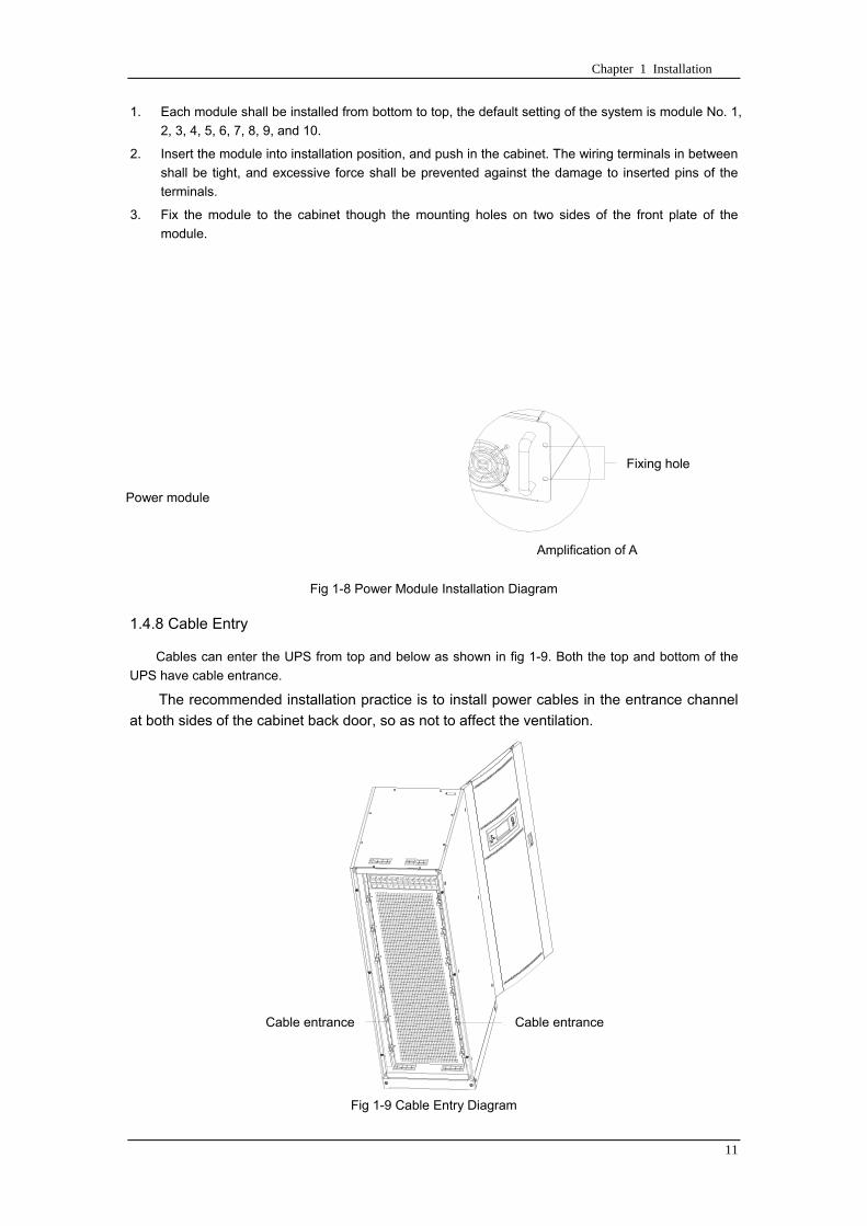
Chapter 1 Installation
11
1 Each module shall be installed from bottom to top the default setting of the system is module No 1
2 3 4 5 6 7 8 9 and 10
2 Insert the module into installation position and push in the cabinet The wiring terminals in between
shall be tight and excessive force shall be prevented against the damage to inserted pins of the
terminals
3 Fix the module to the cabinet though the mounting holes on two sides of the front plate of the
module
固定孔
A处放大
Fig 1-8 Power Module Installation Diagram
148 Cable Entry
Cables can enter the UPS from top and below as shown in fig 1-9 Both the top and bottom of the
UPS have cable entrance
The recommended installation practice is to install power cables in the entrance channel
at both sides of the cabinet back door so as not to affect the ventilation
进线通道 进线通道
Fig 1-9 Cable Entry Diagram
Power module
Fixing hole
Amplification of A
Cable entrance Cable entrance
Chapter 1 Installation
12
15 Protective Devices
For safety concerns it is recommended to install external circuit breakers or other protective devices
for the input AC supply of the UPS system This section provides generic practical information for
qualified installation engineers The installation engineers should have the knowledge of the regulatory
wiring standards and of the equipment to be installed
151 Rectifier and Bypass Input Supply of the UPS
Install suitable protective devices in the distribution unit of the incoming mains supply considering
the power cable current-carrying capacity and overload capacity of the system (see Table 1)Generally
the magnetic circuit breaker with IEC60947-2 tripping curve C (normal) at the 125 of the current listed
in table 1-1 is recommended
Note
For IT power network system 4-pole protective device must be installed on the external input
distribution of the UPS
If protection against earth faults (RCD devices) is required for the upstream of the input supply the
installed device should
Sensitive to DC unidirectional pulses (class A) in the network
Insensitive to transient current pulses
Have an average sensitivity that is adjustable between 03A~1A
The RCCB must be sensitive to DC unidirectional pulses (class A) in the network while insensitive
to transient current pulses as shown in fig 1-10 respectively
Fig 1-10 RCCB sign
152 Battery
A battery unit is composed of 40 batteries connected in series a centreline is drawn from in
between (the joint part between the 20th and 21st battery) plus the line drawn from the front and back
there are altogether 3 lines connected with UPS line contact bank The battery line must push through a
DC circuit breaker before connecting to corresponding UPS line contact bank The detailed wiring please
refer to fig 1-11 below
Fig 1-11 Diagram of batteries connected in series
40 batteries connected in series
Chapter 1 Installation
13
153 UPS Output
A main output switch has been installed in UPS the user shall install the over current protective
device on the bypass of each output of the external distribution cabinet
16 Power Cables
Design the cables according to the descriptions in this section and local regulatory wiring standards
and the environmental conditions should be taken into consideration Refer to IEC60950-1 Table 3B
Warning
Prior to cabling the UPS confirm the status and positions of the switches of the UPS rectifier input
power supply bypass power supply and mains power distribution board
Ensure that these switches are opened and attached with WARNING label so as to prevent
unauthorized operation to these switches
161 Maximum stable state current and configuration of cable system please refer to
table 1-2
Table 1-2 Maximum stable state current and configuration of cable system
System Name MD-06010 MD-09015 MD-12020 MD-10010 MD-15015 MD-20020
Capacity
System
capacity 60kVA 90kVA 120kVA 100kVA 150kVA 200kVA
Module
capacity 10kVA 15kVA 20kVA 10kVA 15kVA 20kVA
Cabinet
dimension 6009001600(WDH mm) 6009002000(WDH mm)
Main
Input
Rated
current A 90 136 180 150 227 300
Cable mm2 25 35 50 50 75 75
Output
Rated
current A 90 136 180 150 227 300
Cable mm2 25 35 50 50 75 75
Battery
Rated
current A 106 160 212 178 265 355
Cable mm2 35 50 75 50 75 90
PE Cable mm2 35 50 75 50 75 90
Warning
FAILURE TO FOLLOW ADEQUATE EARTHING PROCEDURES CAN RESULT IN EMI ELECTRIC
SHOCK HAZARD OR RISK OF FIRE
Chapter 1 Installation
14
162 Cable Connection
Note
The operations described in this section must be performed by authorized electricians or qualified
technical personnel If you have any difficulties do not hesitate to contact our Customer Service amp
Support department at the address given at the beginning of this manual
After the equipment has been finally positioned and secured connect the power cables as
described in the following procedures
1 Verify that all the external input distribution switches of the UPS are completely opened and the
UPS internal maintenance bypass switch is opened Attach necessary warning signs to these
switches to prevent unauthorized operation
2 Open the back door of the cabinet remove the cover and then the input and output terminal
battery terminal and earth terminal are visible
3 Connect the input earth wire to input earth terminal Please note the earth wire shall be connected
in accordance with related local or state regulation
4 For common bypass and rectifier inputs connect the AC input supply cables to the UPS input
terminals (Main input A-B-C-N) and connect the output loaded cable to the UPS output terminals
(Output A-B-C-N) and tighten the connections to 13 Nm (M8 Bolt) ENSURE CORRECT PHASE
ROTATION
5 Connect the battery cables between the UPS battery terminals and battery switch ENSURE
CORRECT PHASE ROTATION
Warning-Hazardous battery terminal voltage of 400Vdc
Ensure the correct polarity connection between the battery terminals and the UPS terminals Positive
terminal to positive terminal negative terminal to negative terminal and disconnect one or more than
one cable between every two layers of batteries Do not connect the cables and close the battery
circuit breakers before getting the approval from the commissioning engineer
6 Re-install all the protective covers
17 Control and Communication Cabling
As shown in fig 1-12 the front panel of the bypass module will provide dry contact interface
(J2~J10) communication interface (RS232 485 and SNMP card interface) as well as LBS interface
干接点接口
SNMP卡接口
RS485接口
RS232接口LBS接口
Fig 1-12 Dry contact interface and communication interface
Dry contact
interface
SNMP card port
LBS port RS232 port
RS485 port
Chapter 1 Installation
15
The UPS accepts external signal from zero-voltage (dry) contacts connected through external dry
contact terminals produced and phoenix terminals that are in bypass module Through software
programming these signals become active when these contacts connect to +24V to ground)The cables
connected to DRY terminal must be separated from power cables Moreover these cables should be
double insulated with a typical 05 to 15 mm2
cross-section area for a maximum connection length
between 25 and 50 meters
171 Dry Contact Interface of Battery and Environmental Temperature Detection
The input dry contact J2 and J3 can detect the temperature of batteries and environment
respectively which can be used in environment monitoring and battery temperature compensation 1
J2 and J3 interfaces diagram are shown in fig 1-13 the description of interface is in table 1-3
Fig 1-13 Diagram of J2 and J3 dry contact for temperature detecting
Table 1-3 Description of input dry contact interface J2 and J3
Position Name Purpose
J21 TEMP_BAT Battery temperature detection
J22 GND Power ground
J31 TEMP_ENV Environment temperature detection
J32 GND Power ground
Note Specified temperature sensor is required for temperature detection (R25=5Ohm
B2550=3275) please confirm with the manufacturer or contact local maintenance engineers when
placing an order
172 Remote EPO Input Port
The UPS has an Emergency Power OFF (EPO) function This function can be activated by pressing
a button on the control panel of the UPS or through a remote contact provided by the user The EPO
pushbutton is protected by a hinged plastic cover
J4 is the input port for remote EPO It requires shorting NC and +24v during normal operation and
the EPO is triggered when opening NC and +24v or shorting NO and +24v The port diagram is shown in
fig 1-14 and port description is shown in table 1-4
Chapter 1 Installation
16
Fig 1-14 Diagram of input port for remote EPO
Table 1-4 Description of input port for remote EPO
Position Name Purpose
J41 EPO_NC EPO is activated when disconnecting fromJ42
J42 +12V +24V connect the common terminal of NC and NO
J43 +12V EPO is activated when shorting with J42
The EPO is triggered when shorting pin 2 and 3 or opening pin 2 and 1 of J4
If an external emergency stop facility is required it is connected via the reserved terminals of J4
The external emergency stop facility needs to use shielded cables to connect to the normally
openclosed remote stop switch between these two pins If this facility is not used then pin 3 and pin 4 of
J4 must be open or pin 1 and pin 2 of J4 must be shorted
Note
1 The emergency stop action within the UPS will shut down the rectifier inverter and static bypass
However it does not internally disconnect the mains input power supply To disconnect ALL power to
the UPS open the upstream input circuit breaker(s) when the EPO is activated
2 Pin 1 and 2 of J4 have been shorted before the UPS is delivered
173 Generator Input Dry Contact
J5 is status interface for generator connection Connect pin 2 of J5 with + 24 power supply it
indicates that the generator has been connected with the system The interface diagram is shown in fig
1-15 and interface description is shown in table 1-5
Chapter 1 Installation
17
Fig 1-15 Diagram of status interface and connection of generator
Table 1-5 Description of maintenance bypass switch and output switch status interface
Position Name Purpose
J51 +24V +24V power supply
J52 GEN Connection status of generator
J53 GND Power ground
174 BCB Input Port
J6 and J7 are the ports of BCB The port diagram is shown in fig 1-16 and description is shown in
table 1-6
BC
B_D
RV
BC
B_C
ON
T
J6 J7
BC
B_O
NL
+24V+24V
+24V
Fig 1-16 BCB Port
Table 1-6 Description of BCB port
Position Name Description
J61 BCB_DRV BCB actuating signal provide the actuating signal of +18V 20mA
J62 BCB_CONT BCB contact status connect with the normally open signal of BCB
J71 GND Power ground
J72 BCB_ONL BCB on-linendashinput (normally open) BCB is on-line when the signal
is connecting with GND
175 Battery Warning Output Dry Contact Interface
J8 is the output dry contact interface which outputs the battery warnings of low or excessive
voltage when the battery voltage is lower than set value an auxiliary dry contact signal will be
provided via the isolation of a relay The interface diagram is shown in fig 1-17 and description is
shown in table 1-7
Generator
Chapter 1 Installation
18
Fig 1-17 Battery warning dry contact interface diagram
Table 1-7 Battery warning dry contact interface description Position Name Purpose
J81 BAT_LOW_NC Battery warning relay (normally closed) will be open during warning
J82 BAT_LOW_NO Battery warning relay (normally open) will be closed during warning
J83 GND Center of battery warning relay
176 Integrated Warning Output Dry Contact Interface
J9 is the integrated warning output dry contact interface when one or more than one preset
warning is triggered the system will send an integrated warning information and provide an auxiliary
dry contact signal via the isolation of a relay The interface diagram is shown in fig 1-18 and description
is shown in table 1-8
Fig 1-18 Integrated warning dry contact interface diagram
Table 1-8 Integrated warning dry contact interface description Position Name Purpose
J91 ALARM_NC Integrated warning relay (normally closed) will be open during warning
J92 ALARM_NO Integrated warning relay (normally open) will be closed during warning
J93 GND Centre of integrated warning relay
177 Mains Failure Warning Output Dry Contact Interface
J10 is the output dry contact interface for mains failure warning when the mains fails the system
will send a mains failure warning information and provide an auxiliary dry contact signal via the isolation
of a relay The interface diagram is shown in fig 1-19 and description is shown in table 1-9
Chapter 1 Installation
19
Fig 1-19 Mains failure warning dry contact interface diagram
Table 1-9 Mains failure warning dry contact interface description Position Name Purpose
J91 UTI_FAIL_NC Mains failure warning relay(normally closed) will be open during
warning
J92 UTI_FAIL_NO Mains failure warning relay normally open) will be closed during
warning
J93 GND Centre of mains failure warning relay
178 RS232 Port and SNMP Card Port
RS232 and RS485 Port provide serial data which can be used for commissioning and maintenance
by authorized engineers or maintainers or can be used for networking or integrated monitoring system in
the service room
SNMP Card Port used for field installation of the communication option card(SNMP card)
179 LBS (Load Bus Synchronizer) Port
The dual bus system (DBS) consists of two independent UPS rack module systems as shown in fig
1-20 The dual bus system is configured for high availability and is suitable for powering the load with
dual inputs If the load is single-input load the static transfer switch and LBS control is recommended to
maintain both UPS outputs synchronized for uninterrupted transfers Please install the system according
to the installation descriptions for different system configurations
The dual bus system is supported by UPS it requires connecting the LBS signal cables of two UPS
when constructing the dual bus system please refer to relevant chapter for detailed configuration and
installation and the system software shall be configured as required
UPS 1
LBS
监控旁路模块 UPS 2
LBS
监控旁路模块
Fig 1-20 LBS Connection Diagram
18 Installation Drawing
Please refer to fig 1-21 fig 1-22 fig 1-23 and fig 1-24
UPS 1 monitoring bypass module
UPS 2 monitoring bypass module
Chapter 1 Installation
20
Fig 1-21 Installation Diagram
Chapter 1 Installation
21
顶视图
2m cabinet front view
16 m cabinet (front view)
Fig 1-22 UPS front view (Unit mm)
Top view
Chapter 1 Installation
22
A
2m cabinet
A
16m cabinet
Fig 1-23 UPS back view
Chapter 1 Installation
23
A
A处放大
Fig 1-24 UPS front view
Amplification of A
24 Chapter 2 Operations
24
Chapter 2 Operations
This chapter introduces the basic knowledge of UPS operations including working principle
operation mode battery management and protection
Warning Hazardous mains voltage andor battery voltage present(s)behind the protective cover
The components that can only be accessed by opening the protective cover with tools cannot be
operated by user
Only qualified service personnel are authorized to remove such covers
21 Introduction
UPS provides the critical load (such as communication and data processing equipment) with high
quality uninterruptible AC power The power from UPS is free from voltage and frequency variations and
disturbances (interruption and spike) experienced at the Mains AC input supply
This is achieved through high frequency double conversion power pulse width modulation (PWM)
associated with full digital signal processing control (DSP) which features high reliability and
convenience for use
211 Principle
As shown in fig 2-1 the AC input mains source is supplied at UPS input and converted into a DC
source This DC source feeds the Inverter that converts the DC source into a clean and input
independent AC source The battery powers the load through the inverter in case of an AC input mains
power failure The utility source can also power the load through the static bypass
When the UPS needs maintenance or repair the load can be transferred to maintenance bypass
without interruption and the power module and bypass module can be removed for maintenance
Chapter 2 Operations 25
25
Fig 2-1 System principle framework
212 Bypass Module
The circuit blocks labeled ldquobypass modulerdquo in fig 2-1 contain electronically controlled switching
circuits that enable the critical load to be connected to either the inverter output or to a bypass power
source via the static bypass line During normal system operation the load is connected to the inverter
but in the event of a UPS overload or inverter failure the load is automatically transferred to the static
bypass line
To provide a clean (no-break) load transfer between the inverter output and static bypass line the
inverter output and bypass supply must be fully synchronized during normal operating conditions This is
achieved through the inverter control electronics which makes the inverter frequency track that of the
static bypass supply provided that the bypass remains within an acceptable frequency window
A manually controlled maintenance bypass supply is incorporated into the UPS design It enables
the critical load to be powered from the utility (bypass) supply while the UPS is shut down for routine
maintenance
Note
When the UPS is operating in bypass mode or on maintenance bypass the connected equipment is
not protected from power failures or surges and sags
22 Operation Mode
The MD UPS is an on-line double-conversion reverse-transfer UPS that permits operation in these
modes
Normal mode
26 Chapter 2 Operations
26
Battery mode
Auto-Restart mode
Bypass mode
Maintenance mode (manual bypass)
ECO mode
Frequency converters mode
221 Normal Mode
The UPS inverter power modules continuously supplies the critical AC load The rectifiercharger
derives power from the AC mains input source and supplies DC power to the inverter while
simultaneously FLOAT or BOOST charging its associated backup battery
222 Battery Mode
Upon failure of the AC mains input power the inverter power modules which obtains power from the
battery supplies the critical AC load There is no interruption in power to the critical load upon failure
After restoration of the AC mains input power the ldquoNormal Moderdquo operation will continue automatically
without the necessity of user intervention
Note UPS can also be started through battery (charged) mode via battery cold start function upon
failure of the AC mains Therefore the battery power can be used independently to improve the
utilization rate of UPS
223 Auto-Restart Mode
The battery may become exhausted following an extended AC mains failure The inverter shuts
down when the battery reaches the End of Discharge voltage (EOD) The UPS may be programmed to
ldquoAuto Recovery after EODrdquo after a delay time if the AC mains recovers This mode and any delay time
are programmed by the commissioning engineer
During the process of delay time the battery will be charged by UPS to prevent any risks to load
equipment from future mains failure
224 Bypass Mode
If the inverter overload capacity is exceeded under normal mode or if the inverter becomes
unavailable for any reason the static transfer switch will perform a transfer of the load from the inverter
to the bypass source with no interruption in power to the critical AC load
225 Maintenance Mode
A manual bypass switch is available to ensure continuity of supply to the critical load when the UPS
becomes unavailable eg during a maintenance procedure
Note This manual bypass switch is fitted in all UPS modules Transfer UPS system to bypass
module for power supply first then close maintenance bypass switch Q2 followed by Q1 and Q3
Warning hazard may occur after transferring to maintenance bypass
After UPS being transferred to maintenance bypass power module and bypass module do not work
no display on LCD and input and output terminals as well as N bus are electrically connected
Chapter 2 Operations 27
27
226 ECO Mode
If economical (ECO) mode is selected the double-conversion UPS will stop to work so as to save
energy During the operation of ECO mode the load power will be supplied by bypass preferentially
When bypass power is within the range of normal frequency and voltage load power will be supplied by
bypass or the system will transfer to inverter input followed by load power interruption which extends
within 34 of the utility period Eg when the frequency is 50Hz the interruption time will be less than
15ms when the frequency is 60Hz the time will be less than 125ms
227 Frequency Converters Mode
If the frequency converter configuration is used by UPS it will provide 50Hz or 60Hz stable output
frequency The range of output frequency is 40Hz~70Hz Under this mode static bypass is unavailable
but battery can be selected according to the actual requirements of battery mode
23 Battery Management
231 Normal Function
The following functions should be fitted by commissioning engineers with specified software
1 Constant current boost charging
Current can be set up
2 Constant voltage boost charging
Voltage of boost charging can be set as required by the type of battery
For Valve Regulated Lead Acid (VRLA) batteries maximum boost charge voltage should not
exceed 24V cell
3 Float charge
Voltage of float charging can be set as required by the type of battery
For VRLA float charge voltage should be between 22V to 23V
4 Float charge temperature compensation (optional)
A coefficient of temperature compensation can be set as required by the type of battery
5 End of discharge (EOD) protection
If the battery voltage is lower than the EOD the battery converter will shut down and the battery is
isolated to avoid further battery discharge EOD is adjustable from 16V to 175V per cell (VRLA) or 09
to 11 V per cell
6 Battery low warning time
It is adjustable between 3 and 60 minutes The default is 5 minutes
232 Advanced Functions (Battery Self-checking and Maintenance)
At periodic intervals 20 of the rated capacity of the battery will be discharged automatically and
the actual load must exceed 20 of the rated UPS (KVA) capacity If the load is less than 20
auto-discharge cannot be executed The periodic interval can be set from 30 to 360 days The battery
self-test can be disabled
ConditionsmdashBattery at float charge for at least 5 hours load equal to 20~100 of rated UPS capacity
TriggermdashManually through the command of ldquoBattery Maintenance Testrdquo in LCD panel or automatically
Battery Self-Test Intervalmdash30-360 days (default setting is battery self-test disabled)
28 Chapter 2 Operations
28
24 Battery Protection
The following functions should be fitted by commissioning engineers with specified software
1 Battery Low Pre-warning
The battery under voltage pre-warning occurs before the end of discharge After this pre-warning
the battery should have the capacity for 3 remaining minutes discharging with full load The time is user
configured from 3 to 60 minutes
2 Battery discharge (EOD)off protection
If the battery voltage is lower than the EOD the battery converter will be shut down EOD is
adjustable from 16V to 175V per cell (VRLA) or 09 to 11 V per cell (NiCd)
3 Battery Circuit Breaker (BCB) Alarm
The alarm occurs when the battery disconnect device disconnects The external battery connects to
the UPS through the external battery circuit breaker The circuit breaker is manually closed and tripped
by the UPS control circuit
Chapter 3 Operation Instructions 29
29
Chapter 3 Operating Steps
This chapter describes UPS operation instructions in detail
All functional keys and LED display involved in operation instructions please refer to chapter 4
During operation the buzzer alarm may occur at any time Select ldquomuterdquo on LED to muffle the audible
alarm
Warning-Hazardous mains voltage andor battery voltage present(s)behind the protective cover
1 The components that can only be accessed by opening the protective cover with tools cannot be
operated by user
2 Only qualified service personnel are authorized to remove such covers
31 Power Switches
As shown in fig 3-1 open the front door of UPS the power switch is visible which includes input
switch output switch and maintenance bypass switch (with anti-misoperation stop plate)
输入开关 输出开关
维修旁路开关
Fig 3-1 Power switch location diagram
32 UPS Start-up
The UPS system only has a maintenance bypass isolating switch and all the other transfers are
processed automatically by internal control logics
Input switch Output switch
Maintenance bypass switch
30 Chapter 3 Operating Instructions
30
321 Normal Module Start
This procedure must be followed when turning on the UPS from a fully powered down condition
The operating procedures are as follows
Warning
This procedure results in mains voltage being applied to the UPS output terminals If any load
equipment is connected to the UPS output terminals please check with the load user that it is safe to
apply power If the load is not ready to receive power then ensure that it is safely to close the output
switch of external distribution cabinet
1 Close UPS output switch and input switch in turns
The LCD starts up at this time The Rectifier indicator flashes during the startup of rectifier The
rectifier enters normal operation state and after about 30s the rectifier indicator goes steady green After
initialization the bypass static switch closes The UPS Mimic LEDs will indicate as shown in table 3-1
Table 3-1 Indicator status
LED Status
Rectifier indicator Green
Battery indicator Red
Bypass indicator Green
Inverter indicator Off
Load indicator Green
Status indicator Green
Note
The output circuit breaker must be closed first followed by input circuit breaker or the rectifier cannot
be started and alarm ldquorectifier failurerdquo
The inverter starts up at this time the inverter indicator flashes After the rectifier enters normal
operation state UPS power supply will transfer from bypass to inverter then the bypass indicator turns
off and load indicator lights The status of indicators is shown in table 3-2
Table 3-2 Indicator Status
LED Status
Rectifier indicator Green
Battery indicator Red
Bypass indicator Off
Inverter indicator Green
Load indicator Green
Status indicator Green
Close external battery switch again battery indicator turns off a few minutes later the battery will be
charged by UPS which will enter normal mode operation The indicator status is shown in table 3-3
Table 3-3 Indicator status
LED Status
Rectifier indicator Green
Battery indicator Green
Bypass indicator Off
Inverter indicator Green
Load indicator Green
Status indicator Green
322 Operating steps of Battery cold Start
1 Check if the batteries have been connected close the external battery switch
Chapter 3 Operation Instructions 31
31
2 Press the red start-up button of battery under the rectifier input circuit breaker for 3 seconds (see fig
3-2)
The LCD starts up at this time The green battery indicator flashes The rectifier enters normal
operation states and after about 30s the battery indicator goes steady green
3 The inverter starts up automatically the green inverter indicator flashes The output of inverter
appears after 60s The UPS works on battery mode
32 Chapter 3 Operating Instructions
32
电池启动按钮
Fig 3-2 Position diagram of battery startup button
Battery startup button
Chapter 3 Operation Instructions 33
33
33 Procedure for Switching between Operation Modes
331 Procedure for Switching the UPS into Battery mode from Normal Mode
Open input switch to cut off the mains UPS enters the battery mode If UPS should be switched to
normal mode wait for a few seconds before close input switch so as to supply the mains again 10s
later the rectifier will start up automatically to supply power to the inverter
332 Procedure for Switching the UPS into Bypass mode from Normal Mode
Select ldquoTran Byprdquo on the LCD or press ldquooffrdquo buttons of each power module in turn
Note
In bypass mode the load is directly fed by the mains power instead of the pure AC power from the
inverter
333 Procedure for Switching the UPS into Normal from Bypass Mode
Select exit bypass mode on the LCD
334 Procedure for Switching the UPS into a Maintenance Bypass from Normal Mode
In normal operation this operation instruction will switch the load from inverter input to maintenance
bypass
Caution
Before making this operation read messages on display to be sure that bypass supply is regular and
the inverter is synchronous with it so as not to have a risk of a short interruption in powering the load
1 Press ldquoTran Byprdquo on the LCD or press ldquooffrdquo on each power module in turns
If press rdquoTran Byprdquo on the LCD the inverter indicator will flash green and the buzzer will alarm
If press ldquooffrdquo on each power module in turns the inverter indicator will go off and the buzzer will
alarm
The load will be transferred to static bypass and the inverter is closed
2 Close maintenance bypass switch Q2 the load power will be supplied by maintenance bypass and
then open the inverter circuit breaker Q1 output switch Q3 and battery switch
Warning
If you need to maintain the module wait for 10 minutes to let the DC bus capacitor fully discharge
before removing corresponding module
335 Procedure for Switching the UPS into Normal from a Maintenance Bypass Mode
This procedure can transfer the load to normal main mode when the UPS is operating under the
maintenance bypass mode
1 Close output switch Q3 and main switch Q1
The bypass indicator goes green and the load power will be supplied by bypass and maintenance
bypass
2 Open maintenance bypass switch Q2
34 Chapter 3 Operating Instructions
34
The load power is supplied by bypass In the meantime the rectifier starts up rectifier indicator goes
green 30s later at this time the inverter will start up automatically and transfer to inverter mode 1 min
later automatically
3 Close external battery switch the battery indicator goes off Check if the battery voltage on LCD
display is normal
34 Procedure for Completely Powering down a UPS
If you need to power down the UPS completely follow the procedures in section 334 to transfer the
UPS from normal mode to maintenance bypass mode
If you need to isolate the UPS from the AC power supply you should open the external input switch
35 EPO Procedure
The EPO button on UPS operator control and display panel is designed to switch off the UPS in
emergency conditions (eg fire flood etc)To achieve this just press the EPO button and the system
will turn off the rectifier inverter and stop powering the load immediately (including the inverter and
bypass output) and the battery stops charging or discharging
If the input utility is present the UPS control circuit will remain active however the output will be
turned off To completely isolate the UPS you need to open the external mains input supply to the UPS
rack
36 Language Selection
The LCD is available in two languages Chinese English and Korean
The language can be selected through LCD prompt window
37 Control Password
When the LCD displays ldquoinput control password 1rdquo the initial password is 12345678
Chapter 4 Operator Control and Display Panel 35
35
Chapter 4 Operator Control and Display Panel
This chapter introduces the functions and operation instructions of the parts on UPS operator control
and display panel in detail and provides LCD display information including LCD display types detailed
menu information prompt window information and UPS alarm list
41 Introduction
The operator control and display panel is located on the front panel of the UPS Through this LCD
panel the operator can operate and control the UPS and check all measured parameters UPS and
battery status and event and alarm logs The operator control panel is divided into three functional areas
as shown in fig 4-1 mimic current path LCD display amp Menu keys and Control and Operation Keys The
detailed description of parts on operator control and display panel is shown in table 4-1
Fig 4-1 UPS operator control and display panel
Table 4-1 Description of UPS operator control and display panel
Part No Function Button Function
REC Rectifier indicator EPO EPO switch
BAT Battery indicator TAB switch
BYP Bypass indicator ENTER confirm
INV Inverter indicator ESC exit
OUTPUT Load indicator
STATUS Status indicator
36 Chapter 4 Operator Control and Display Panel
36
411 LED Indicator
The LEDs shown on the mini current path represent the various UPS power paths and show the
current UPS operating status The status description of indicators is shown in table 4-2
Table 4-2 Status description of indicator
Indicator State Purpose
Rectifier
indicator
Steady green Rectifier normal for all modules
Flashing green Rectifier for at least on module normal mains normal
Steady red Rectifier fault
Flashing red Mains abnormal for at least one module
Off Rectifier not operating
Battery
indicator
Steady green Battery charging
Flashing green Battery discharging
Steady red
Battery abnormal (battery failure no battery or battery reverse) or
battery converter abnormal (failure over current or over temperature)
EOD
Flashing red Battery low voltage
Off Battery and battery converter normal battery not charging
Bypass
indicator
Steady green Load power supplied by bypass
Steady red Bypass power abnormal or out of normal range or static bypass
switch fault
Flashing red Bypass voltage abnormal
Off Bypass normal
Inverter
indicator
Steady green Load power supplied by inverter
Flashing green Inverter On start synchronization of standby (ECO mode) for at least
one module
Steady red System power not supplied by inverter inverter fault for at least one
module
Flashing red System power supplied by inverter inverter fault for at least one
module
Off Inverter not operating for all modules
Load
indicator
Steady green UPS output ON and normal
Steady red UPS output overload and overtime or output short or output no power
supply
Flashing red Overload output of UPS
Off No output of UPS
Status
indicator
Steady green Normal operation
Steady red Failure
412 Audible Alarm (buzzer)
There are two different types of audible alarm during UPS operation as shown in table 4-3
Table 4-3 description of audible alarm
Alarm Purpose
Two short alarm with
a long one
when system has general alarm (for example AC fault) this audible alarm
can be heard
Continuous alarm When system has serious faults (for example fuse or hardware fault) this
audible alarm can be heard
Chapter 4 Operator Control and Display Panel 37
37
413 Functional Keys
There are 4 functional keys on operator control and display panel which are used together with LCD
The functions description is shown in table 4-4
Table 4-4 Functions of functional keys
Functional key Functions
EPO switch To cut off the load power to shut down the rectifier inverter static
bypass and battery
TAB switch
ENTER confirm
ESC exit
42 LCD Display Type
Following the self-check of UPS LCD display the main LCD display is shown as fig 4-2 which can
be divided into three display windows system information data command and current record
Fig 4-2 Main LCD display
The description of LCD icon is shown in table 4-5
Table 4-5 Description of LCD icons
Icon Description
Bypass parameter
UPS system
information
window
Data
command
window
Current
record
window
38 Chapter 4 Operator Control and Display Panel
38
Icon Description
Main input parameter
History file system information
Function setting (display calibration password setting time setting date format
communication protocol and language setting) system setting (used by product
maintainers)
Battery data battery parameter setting (used by service staff)
Test (battery self-test battery maintenance)
Functional keys used by service staff (fault clearing history file clearing noise
clearing manual switch of bypass) userrsquos setting (system mode machine
number system ID output voltage adjustment frequency tracing speed
frequency tracing limit)
Output parameter
Load
Noise clearing noise clearing cancel
Log view page updown
Select a icon on LCD as shown in fig 4-3 to view the UPS parameter represented by this icon eg
select the LCD will display the data of system main input
Chapter 4 Operator Control and Display Panel 39
39
Fig 4-3 Select data
Or select and confirm a module as shown in fig 4-4 the LCD will display the
operating status of this module
Fig 4-4 Select a module
40 Chapter 4 Operator Control and Display Panel
40
Select in the operating status of a module to view the main input data of this module
Select in the operating status of a module to view the main output data of this module
Select in the operating status of a module to view the load data of this module
Select in the operating status of a module to view the maintenance code and module
software code of this module
Select to return to the previous page
Select to return to the home page
Default display
During the operation of system if therersquos no alarm in 2 min the system will display default After a
short delay the backlight of LCD display goes off press any key to reactivate the display
43 Detailed Description of Menu Items
The LCD main display shown in fig 4-2 is described in details below
UPS information window
UPS information window display the current time and UPS name The information of the window is
not necessary for the user to operate The information of this window is given in table 4-6
Table 4-6 Description of items in UPS system information window
Display contents Meaning
MD12020 UPS Name
1200 Current Time (format 24 hours hours minute)
UPS menu and data window
UPS menu window displays the menu name of data window while the data window displays the
related contents of selected menu in menu window Select UPS menu and data window to browse
related parameters of UPS and set related functions The details are given in table 4-7
Table 4-7 Item description of UPS menu and data window
Menu name Menu item Meaning
Main input
V phase(V) V phase
I phase(A) I phase
Freq(Hz) Input frequency
PF Power factor
Bypass input
V phase(V) V phase
Freq (Hz) Bypass frequency
I phase(A) I phase
PF Power factor
AC output
V phase(V) V phase
I phase(A) I phase
Freq (Hz) Output frequency
PF Power factor
This UPS Sout (kVA) Sout Apparent Power
Chapter 4 Operator Control and Display Panel 41
41
Menu name Menu item Meaning
modulersquos
load
Pout (kW) Pout Active Power
Qout (kVAR) Qout Reactive Power
Load () Load (The percentage of the UPS rating load)
Battery data
Environmental
Temp Environmental Temp
Battery
voltage(V) Battery bus voltage
Battery current
A) Battery bus current
Battery
Temp() Battery Temp
Remaining Time
(Min) Remaining battery backup time
Battery capacity
() The percentage compared with new battery capacity
battery
equalized
charging
Battery is equalized charging
battery float
charging Battery is float charging
Battery
disconnected Battery is not connected
Current
record (current alarm)
Display all current alarm The alarm list displayed on LCD of
UPS operator control and display panel please refer to table 4-9
History
record (history alarm)
Display all history alarm The alarm list displayed on LCD of
UPS operator control and display panel please refer to table 4-9
Menu
Language
(language
option) 2 languages can be selected
Settings
Display
calibration Adjust the accuracy of LCD display
Date format set MM DD YYYY and YYYY MM DD formats can be selected
Date amp Time DateTime set
Language set User can set the language (Chinese and English)
Communication
mode
Set communication mode MODBUS Power protocol and
company custom protocol modes can be selected Power
protocol mode can be divided into equipment address baud
rate set MODBUS protocol mode can be divided into
communication mode (RTUASCⅡ) equipment address
baud rate and check-bit set Company custom protocol mode
is the customed protocol of the company no option is
available
Control
password set User can modify control password 1
Test
Command
(Battery Test
Control
Battery
maintenance
test
This test will lead to the battery being partly discharged to
activate battery at the same time the approximate battery
capacity will be obtained Bypass must be in normal condition
the battery capacity should be above 25
42 Chapter 4 Operator Control and Display Panel
42
Menu name Menu item Meaning
Battery
self-check test
UPS switches to battery discharge for discharging to test if the
battery is normal Bypass must be in normal condition the
battery capacity should be above 25
Stop testing Manually Stop the test including maintenance test capacity test
UPS system
information
Monitoring
software version Provide monitoring software version
Rectified
software version Provide rectified software version
Inverted
software version Provide inverted software version
Serial No The serial no set when delivery from the factory
Rated
information Network setting of system operating
Module type Type of the module
44 Alarm List
The follow table 4-8 gives the complete list of all the UPS events displayed by history record window
and current record window
Table 4-8 Alarm List
Alarm Explanation
UPS power supply The system is in normal inverted power supply status
Bypass power
supply The system is in bypass power supply status
No power supply System no output
Battery equalized
charging Battery is in boost charging
Battery float
charging Battery is in float charging
Battery discharging The system is operating in battery discharging status
Battery connected Battery is connected
Battery
disconnected Battery is not connected
Maintenance circuit
breaker close Maintenance circuit breaker is close
Maintenance circuit
breaker open Maintenance circuit breaker is open
Emergency
shutdown System emergency shutdownEPO
Generator
connected External generator is connected
Mains abnormal Input mains abnormal
Bypass phase
conversion Bypass input phase converse
Bypass voltage
abnormal Bypass input voltage abnormal
Bypass fault Bypass fault
Bypass overload Bypass output is overload
Up to bypass
overtime of Bypass is overtime of overload
Chapter 4 Operator Control and Display Panel 43
43
Alarm Explanation
overload
Bypass frequency
tracing exceeds Bypass frequency is out of the tracing range
Switch times up to
in this hour
The times of switch between bypass and inverter exceeds 5 times in the latest
hour
Output short System output short
Battery EOD Battery voltage achieves shutdown point
Battery self-check The system enters battery self-check mode
Battery self-check
success Battery normal during system self-check
Battery manual
check failure Battery fault during system self-check
Battery
maintenance The system is in battery maintenance status
Battery
maintenance
success
Battery maintenance status completes
Battery
maintenance failure Battery maintenance process is not normal
Stop testing Battery self-check or battery maintenance status stops
Fault clearing Clear the alarmed fault
Delete history
record Delete all history record
N communication
node connected N module is connected to UPS system
N communication
node disconnected N module is not connected to UPS system
N rectifier fault N module rectifier fault
N inverter fault N module inverter fault
N rectifier
overheat N module rectifier overheat
N fan fault N module fan fault
N output overload N module output overload
N overtime of
overload N module output overtime of overload
N inverter
overheat N module inverter overheat
Inverter power
supply ban Inverter power ban supply
Manual switch of
bypass Switch the system to bypass output manually
Cancel manual
switch of bypass Switch the system from bypass to inverter output manually
Battery low voltage Battery low voltage
Battery reversal Battery polarity reversal
N inverter
protection N module inverter protection
Input N line
disconnected System input N line is not connected
Bypass fan fault Bypass module fan fault
N manual N module manual power off
44 Chapter 4 Operator Control and Display Panel
44
Alarm Explanation
shutdown
Chapter 5 Maintenance 45
45
Chapter 5 Installation of Parallel Operation System
The parallel operation system is installed as required by the installation procedures of the single
system and this chapter
The single devices are put parallel and connected as shown in fig 5-1 and the difference between
the lengths of the output cables of the single devices is not more than 10m It is recommended to use an
external bypass cabinet to facilitate maintenance and system testing
Fig 5-1 Typical 1+N parallel operation system
Note when the load exceeds is the capacity of the single device the maintenance bypass
switch CB3 must be removed
The cables for the parallel operation provide double insulation shielding up to 30m long the control
cables for the parallel operation must be connected with all single devices to form a closed loop as
shown in fig5-2
Other power supplies
Rectifier
Charger Inverter Inverter
Output power supply
Load connected
Mains power input L1 L2 L3 N terminal
Mains power inputL1 L2 L3 N terminal
Rectifier
Charger
46 Chapter 5 Maintenance
46
Fig5-2 parallel cables
Chapter 5 Maintenance 47
47
Chapter 6 Maintenance
This chapter introduces UPS maintenance including the maintenance instructions of power module
monitoring bypass module and the change method of dust filter
61 Instruction to Power Bypass and Output Power Distribution
Module
611 Precautions
1 Only maintaining engineers can maintain the power module and monitoring bypass module
2 In principle the power module and bypass module should be disassembled from top to bottom so
as to prevent any inclination from high gravity centre of the cabinet
3 To ensure the safety before maintaining power module and bypass module be sure to use a
multimeter to measure the DC bus capacitor voltage and ensure the voltage is below 60V before
operation and use a multimeter to measure the voltage between operating parts and the earth to
ensure the voltage is lower than hazardous voltage ie DC voltage is lower than 60Vdc and AC
maximum Voltage is lower than 424Vac
4 Bypass module doesnrsquot support any hot insertion and extraction only when UPS is in maintenance
bypass mode or UPS is completely power off can the bypass module be disassembled
5 The module can be maintained 10 mins after extracting power module and bypass module which
can be inserted into the cabinet 10 mins later
612 Instruction to Power Module
Suppose UPS were in normal mode and bypass were normal a module shall be maintained at
first
1 Press OFF of the module with a pin point or other tiny matter the module will shut down
automatically and exit the system
Note ensure if the remaining module will be overload when exiting a module If therersquos any risk of
overload transfer the whole UPS system to bypass followed by other operations
2 Take off the fixing bolt on the two sides of front and back plate of power module 10 mins later
extract the module from the cabinet
3 After maintaining the module push the module into the equipment cabinet (the interval between
two modules shall be more than 10s) fix the screw on the two sides Then the module will be
connected to UPS system automatically
613 Instruction to Bypass Module
Suppose UPS were in normal mode and the bypass were normal
1 Select LCD touch screen manual switch of bypass the UPS power will be supplied by bypass
2 Close maintenance bypass switch the UPS power will be supplied by maintenance bypass
3 Open UPS output switch and input switch
4 Open external battery switch
48 Chapter 5 Maintenance
48
5 Take off the fixing bolt at the two sides of front board of bypass module extract the front cable
assembly of the module and extract the module from the cabinet
6 After maintaining the module insert the module into the cabinet tighten the screw at the two sides
and connect the front cable assembly of manufacturerrsquos module
7 Close UPS output switch and input switch in turn
2 mins later bypass indicator on the operator control and display panel lights on which indicates
the normal power supply of bypass
8 Open maintenance bypass switch the inverter starts automatically 60s later the UPS will transfer
to normal mode
62 Replacing Dust Screen (optional)
As shown in fig 5-1 there are 3~4 dust filters on the back of UPSrsquo front door each screen is held in
place by a bracket on either side of each filter The procedure of replacing each filter is as follows
1 Open the UPSrsquo front door and locate the filters on the back side of the front door
2 Remove one bracket
3 Remove the dust screen to be replaced and insert the clean one
4 Reinstall the bracket
防尘网固定条
Fig 5-1 Dust screen on the back side of UPS front door
Bracket
Dust screen
Appendix 2 Toxic or Hazardous Materials or Elements Identification Table 49
49
Chapter 7 Product Specification
This chapter provides UPS product specification
71 Applicable Standards
The UPS has been designed to conform to the following European and international standards
Table 6-1 Compliance with European and International Standards
Item Normative reference
General safety requirements for UPS
used in operator access areas EN50091-1-1IEC62040-1-1AS 62040-1-1
Electromagnetic compatibility (EMC)
requirements for UPS EN50091-2IEC62040-2AS 62040-2(C3)
Method of specifying the performance
and test requirements of UPS EN50091-3IEC62040-3AS 62040-3(VFI SS 111)
Note The above mentioned product standards incorporate relevant compliance clauses with generic
IEC and EN standards for safety (IECENAS60950) electromagnetic emission and immunity
(IECEN AS61000 series) and construction (IECENAS60146 series and 60950)
72 Environmental Characteristics
Table 6-2 Environmental Properties
Items Unit Requirements
Acoustic noise level at 1
meter dB 550
Altitude of Operation m le1000m above sea level derate power by 1 per 100m
between 1000m and 2000m
Relative Humidity RH 0 to 95 non condensing
Operating Temperature 0 to 40 deg Battery life is halved for every 10degC increase
above 20degC
UPS Storage-Transport
Temperature -20~70
Recommended Battery
Storage Temperature -20~30 (20degC for optimum battery storage)
73 Mechanical Characteristics
Table 6-3 Mechanical Properties
Cabinet Specification Unit MD6010 MD9015
MD12020
MD10010 MD15015
MD20020
Mechanical Dimension
WtimesDtimesH mm 600times900times1600 600times900times2000
Weight kg 151 182
Color NA Black
Protection Level
IEC(60529) NA IP20
50 Chapter 5 Maintenance
50
Module type Unit MU10 MU15 MU20
Mechanical Dimension
WtimesDtimesH mm 440times590times134
Weight kg 21 22 22
Color NA Black
74 Electrical Characteristics (Input Rectifier)
Table 6-4 Rectifier AC input (mains)
Items Unit Parameter
Rated AC Input
Voltage Vac
380400415(three-phase and sharing neutral with the
bypass input)
Input voltage range Vac -40~+25
Frequency2 Hz 5060(range 40Hz~70Hz)
Power factor kWkVA full load 099
THD THDI 3
75 Electrical Characteristics (Intermediate DC Link)
Table 6-5 Battery
Items Unit Parameters
Battery bus
voltage Vdc Nominal plusmn240V one-side range 198V~288V
Quantity of
lead-acid cells Nominal 40=[1 battery(12V) ] 240=[1 battery(2V) ]
Float charge
voltage Vcell(VRLA)
225Vcell(selectable from 22Vcell~235Vcell)
Constant current and constant voltage charge mode
Temperature
compensation mVcl -30(selectable from 0~-50 25 or 30 or inhibit)
Ripple voltage V float le1
Ripple current C10 le5
equalized
charge voltage VRLA
24Vcell(selectable from 230Vcell~245Vcell)
Constant current and constant voltage charge mode
final
discharging
voltage
Vcell(VRLA)
165Vcell(selectable from 160Vcell ~ 1750Vcell) 06C
discharge current
175Vcell (selectable from 165Vcell ~ 18Vcell) 015C
discharge current
(EOD voltage changes linearly within the set range according to
discharge current)
Battery Charge Vcell 24Vcell(selectable from 23Vcell~245Vcell)
Constant current and constant voltage charge mode
Battery
Charging Power
Max Current
kW 10 UPS capacity (selectable from 0~20 UPS capacity)
Appendix 2 Toxic or Hazardous Materials or Elements Identification Table 51
51
76 Electrical Characteristics (Inverter Output)
Table 6-6 Inverter Output (to important load)
Rated
capacity(kVA) Unit 10~200
Rated AC voltage1 Vac 380400415(three-phase four-wire and sharing neutral with the
bypass)
Freqency2 Hz 5060
overload
110 load 1 hour
125 load 10min
150 load 1min
>150 load 200ms
Fault current 340 short current limitation for 200ms
Non linear load
capability 3 100
Neutral current
capability 170
Steady state
voltage stability
plusmn1(balanced load)
plusmn15(100 imbalance load)
Transient voltage
response 4 plusmn5
THD <15(linear load) <5(non linear load3)
Synchronization -
Window Rated frequency plusmn2Hz(selectable plusmn1~plusmn5Hz)
Max change rate of
synch frequency Hzs 1 selectable 01~5
Inverter voltage
range V(ac) plusmn5
Note
1 Factory setting is 380V Commissioning engineers can set to 400V or 415V
2 Factory setting is 50Hz Commissioning engineers can set to 60Hz
3 EN50091-3(1458) peak value factor is 3 1
4 IEC62040-3EN50091-3 including 0~100~0 load transient the recovery time is half
circle to within 5 of stable output voltage
52 Chapter 5 Maintenance
52
77 Electrical Characteristics(Bypass Mains Input)
Table 6-7 Bypass Mains Input
Rated
capacity(kVA) Unit 60 90 100 120 150 200
Rated AC
Voltage1 Vac
380400415
three-phase four-wire sharing neutral with the rectifier input and providing neutral
reference for the output
Rated current A
91380V
87400V
83415V
136380V
130400V
124415V
151380V
144400V
138415V
182380V
174400V
166415V
227380V
216400V
207415V
302380V
288400V
276415V
Overload
125 load long term
130 load 1 hour
150 load 6min
1000 load 100ms
Superior
protection
bypass line
NA Thermal-magnetic breaker the capacity is 125 of rated current output
IEC60947-2 curve C
Current rating
of neutral cable A 17timesIn
Frequency2 Hz 5060
Switch time
(between
bypass and
inverter)
ms Synchronized switch le1ms
Bypass voltage
tolerance Vac
Upper limit +10+15or+20 default +20
Lower limit -10 -20 -30 or-40 default-20
(acceptable stable bypass voltage delay 10s)
Bypass
frequency
tolerance
plusmn25 plusmn5 plusmn10 or plusmn20 default plusmn10
Synchronizatio
n-Window Hz Rated frequencyplusmn2Hz (selectable from plusmn05Hz~plusmn5Hz)
Note
1 Factory setting is 400V Commissioning engineers can set to 380V or 415V
2 Factory setting is 50Hz Commissioning engineers can set to 60Hz For example UPS is set to frequency
inverter mode and then bypass status will be neglected
78 Efficiency
Table 6-8 Efficiency Loss and Air Exchange
Rated Efficiency (kVA) Unit 10~200kVA
Normal mode(dual conversion) 95
ECO mode 99
Battery discharging efficiency (DCAC) (battery at nominal voltage 480Vdc and full-rated linear load)
battery mode 95
Appendix 2 Toxic or Hazardous Materials or Elements Identification Table 53
53
Appendix A A Guidebook to Ordering and Selection of MU System
MD series UPS module can be divided into equipment cabinet and power module For the cabinet
lectotype please refer to the description in fig 6-1
Fig 6-1 Cabinet Selection
For single power module type please refers to the description in fig 6-2
Fig 6-2 Power Module Selection
Egg the requirements of a plant room are given below
The maximum power supply of the plant room is 120kVA however it is expected to be expanded to
200kVA in 3-5 years Therefore a 200kVA cabinet and 6 20kVA power module can be purchased to
constitute an uninterrupted 120kVA power system which can be expanded to 200kVA on-line The order
symbol is
1 set MD20020
6 set MU20
Option list
MD-SNMP card remote network monitoring card
MD-1600 dust filter dust screen for 16m cabinet
MD-2000 dust filter dust screen for 2m cabinet
Represents the capacity of a single power module
10 represents 10kVA
15 represents 15kVA
20 represents 20kVA
represents a single power module
Represents UPS system capacitypower module
06010 represents 60kVA10kVA
09015 represents 90kVA15kVA
12020 represents 120kVA20kVA
15015 represents 150kVA15kVA
20020 represents 200kVA20kVA
MD represents UPS cabinet
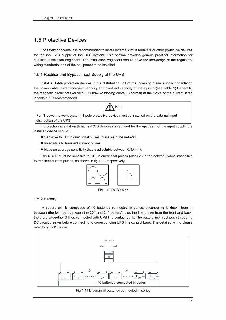
Chapter 1 Installation
12
15 Protective Devices
For safety concerns it is recommended to install external circuit breakers or other protective devices
for the input AC supply of the UPS system This section provides generic practical information for
qualified installation engineers The installation engineers should have the knowledge of the regulatory
wiring standards and of the equipment to be installed
151 Rectifier and Bypass Input Supply of the UPS
Install suitable protective devices in the distribution unit of the incoming mains supply considering
the power cable current-carrying capacity and overload capacity of the system (see Table 1)Generally
the magnetic circuit breaker with IEC60947-2 tripping curve C (normal) at the 125 of the current listed
in table 1-1 is recommended
Note
For IT power network system 4-pole protective device must be installed on the external input
distribution of the UPS
If protection against earth faults (RCD devices) is required for the upstream of the input supply the
installed device should
Sensitive to DC unidirectional pulses (class A) in the network
Insensitive to transient current pulses
Have an average sensitivity that is adjustable between 03A~1A
The RCCB must be sensitive to DC unidirectional pulses (class A) in the network while insensitive
to transient current pulses as shown in fig 1-10 respectively
Fig 1-10 RCCB sign
152 Battery
A battery unit is composed of 40 batteries connected in series a centreline is drawn from in
between (the joint part between the 20th and 21st battery) plus the line drawn from the front and back
there are altogether 3 lines connected with UPS line contact bank The battery line must push through a
DC circuit breaker before connecting to corresponding UPS line contact bank The detailed wiring please
refer to fig 1-11 below
Fig 1-11 Diagram of batteries connected in series
40 batteries connected in series
Chapter 1 Installation
13
153 UPS Output
A main output switch has been installed in UPS the user shall install the over current protective
device on the bypass of each output of the external distribution cabinet
16 Power Cables
Design the cables according to the descriptions in this section and local regulatory wiring standards
and the environmental conditions should be taken into consideration Refer to IEC60950-1 Table 3B
Warning
Prior to cabling the UPS confirm the status and positions of the switches of the UPS rectifier input
power supply bypass power supply and mains power distribution board
Ensure that these switches are opened and attached with WARNING label so as to prevent
unauthorized operation to these switches
161 Maximum stable state current and configuration of cable system please refer to
table 1-2
Table 1-2 Maximum stable state current and configuration of cable system
System Name MD-06010 MD-09015 MD-12020 MD-10010 MD-15015 MD-20020
Capacity
System
capacity 60kVA 90kVA 120kVA 100kVA 150kVA 200kVA
Module
capacity 10kVA 15kVA 20kVA 10kVA 15kVA 20kVA
Cabinet
dimension 6009001600(WDH mm) 6009002000(WDH mm)
Main
Input
Rated
current A 90 136 180 150 227 300
Cable mm2 25 35 50 50 75 75
Output
Rated
current A 90 136 180 150 227 300
Cable mm2 25 35 50 50 75 75
Battery
Rated
current A 106 160 212 178 265 355
Cable mm2 35 50 75 50 75 90
PE Cable mm2 35 50 75 50 75 90
Warning
FAILURE TO FOLLOW ADEQUATE EARTHING PROCEDURES CAN RESULT IN EMI ELECTRIC
SHOCK HAZARD OR RISK OF FIRE
Chapter 1 Installation
14
162 Cable Connection
Note
The operations described in this section must be performed by authorized electricians or qualified
technical personnel If you have any difficulties do not hesitate to contact our Customer Service amp
Support department at the address given at the beginning of this manual
After the equipment has been finally positioned and secured connect the power cables as
described in the following procedures
1 Verify that all the external input distribution switches of the UPS are completely opened and the
UPS internal maintenance bypass switch is opened Attach necessary warning signs to these
switches to prevent unauthorized operation
2 Open the back door of the cabinet remove the cover and then the input and output terminal
battery terminal and earth terminal are visible
3 Connect the input earth wire to input earth terminal Please note the earth wire shall be connected
in accordance with related local or state regulation
4 For common bypass and rectifier inputs connect the AC input supply cables to the UPS input
terminals (Main input A-B-C-N) and connect the output loaded cable to the UPS output terminals
(Output A-B-C-N) and tighten the connections to 13 Nm (M8 Bolt) ENSURE CORRECT PHASE
ROTATION
5 Connect the battery cables between the UPS battery terminals and battery switch ENSURE
CORRECT PHASE ROTATION
Warning-Hazardous battery terminal voltage of 400Vdc
Ensure the correct polarity connection between the battery terminals and the UPS terminals Positive
terminal to positive terminal negative terminal to negative terminal and disconnect one or more than
one cable between every two layers of batteries Do not connect the cables and close the battery
circuit breakers before getting the approval from the commissioning engineer
6 Re-install all the protective covers
17 Control and Communication Cabling
As shown in fig 1-12 the front panel of the bypass module will provide dry contact interface
(J2~J10) communication interface (RS232 485 and SNMP card interface) as well as LBS interface
干接点接口
SNMP卡接口
RS485接口
RS232接口LBS接口
Fig 1-12 Dry contact interface and communication interface
Dry contact
interface
SNMP card port
LBS port RS232 port
RS485 port
Chapter 1 Installation
15
The UPS accepts external signal from zero-voltage (dry) contacts connected through external dry
contact terminals produced and phoenix terminals that are in bypass module Through software
programming these signals become active when these contacts connect to +24V to ground)The cables
connected to DRY terminal must be separated from power cables Moreover these cables should be
double insulated with a typical 05 to 15 mm2
cross-section area for a maximum connection length
between 25 and 50 meters
171 Dry Contact Interface of Battery and Environmental Temperature Detection
The input dry contact J2 and J3 can detect the temperature of batteries and environment
respectively which can be used in environment monitoring and battery temperature compensation 1
J2 and J3 interfaces diagram are shown in fig 1-13 the description of interface is in table 1-3
Fig 1-13 Diagram of J2 and J3 dry contact for temperature detecting
Table 1-3 Description of input dry contact interface J2 and J3
Position Name Purpose
J21 TEMP_BAT Battery temperature detection
J22 GND Power ground
J31 TEMP_ENV Environment temperature detection
J32 GND Power ground
Note Specified temperature sensor is required for temperature detection (R25=5Ohm
B2550=3275) please confirm with the manufacturer or contact local maintenance engineers when
placing an order
172 Remote EPO Input Port
The UPS has an Emergency Power OFF (EPO) function This function can be activated by pressing
a button on the control panel of the UPS or through a remote contact provided by the user The EPO
pushbutton is protected by a hinged plastic cover
J4 is the input port for remote EPO It requires shorting NC and +24v during normal operation and
the EPO is triggered when opening NC and +24v or shorting NO and +24v The port diagram is shown in
fig 1-14 and port description is shown in table 1-4
Chapter 1 Installation
16
Fig 1-14 Diagram of input port for remote EPO
Table 1-4 Description of input port for remote EPO
Position Name Purpose
J41 EPO_NC EPO is activated when disconnecting fromJ42
J42 +12V +24V connect the common terminal of NC and NO
J43 +12V EPO is activated when shorting with J42
The EPO is triggered when shorting pin 2 and 3 or opening pin 2 and 1 of J4
If an external emergency stop facility is required it is connected via the reserved terminals of J4
The external emergency stop facility needs to use shielded cables to connect to the normally
openclosed remote stop switch between these two pins If this facility is not used then pin 3 and pin 4 of
J4 must be open or pin 1 and pin 2 of J4 must be shorted
Note
1 The emergency stop action within the UPS will shut down the rectifier inverter and static bypass
However it does not internally disconnect the mains input power supply To disconnect ALL power to
the UPS open the upstream input circuit breaker(s) when the EPO is activated
2 Pin 1 and 2 of J4 have been shorted before the UPS is delivered
173 Generator Input Dry Contact
J5 is status interface for generator connection Connect pin 2 of J5 with + 24 power supply it
indicates that the generator has been connected with the system The interface diagram is shown in fig
1-15 and interface description is shown in table 1-5
Chapter 1 Installation
17
Fig 1-15 Diagram of status interface and connection of generator
Table 1-5 Description of maintenance bypass switch and output switch status interface
Position Name Purpose
J51 +24V +24V power supply
J52 GEN Connection status of generator
J53 GND Power ground
174 BCB Input Port
J6 and J7 are the ports of BCB The port diagram is shown in fig 1-16 and description is shown in
table 1-6
BC
B_D
RV
BC
B_C
ON
T
J6 J7
BC
B_O
NL
+24V+24V
+24V
Fig 1-16 BCB Port
Table 1-6 Description of BCB port
Position Name Description
J61 BCB_DRV BCB actuating signal provide the actuating signal of +18V 20mA
J62 BCB_CONT BCB contact status connect with the normally open signal of BCB
J71 GND Power ground
J72 BCB_ONL BCB on-linendashinput (normally open) BCB is on-line when the signal
is connecting with GND
175 Battery Warning Output Dry Contact Interface
J8 is the output dry contact interface which outputs the battery warnings of low or excessive
voltage when the battery voltage is lower than set value an auxiliary dry contact signal will be
provided via the isolation of a relay The interface diagram is shown in fig 1-17 and description is
shown in table 1-7
Generator
Chapter 1 Installation
18
Fig 1-17 Battery warning dry contact interface diagram
Table 1-7 Battery warning dry contact interface description Position Name Purpose
J81 BAT_LOW_NC Battery warning relay (normally closed) will be open during warning
J82 BAT_LOW_NO Battery warning relay (normally open) will be closed during warning
J83 GND Center of battery warning relay
176 Integrated Warning Output Dry Contact Interface
J9 is the integrated warning output dry contact interface when one or more than one preset
warning is triggered the system will send an integrated warning information and provide an auxiliary
dry contact signal via the isolation of a relay The interface diagram is shown in fig 1-18 and description
is shown in table 1-8
Fig 1-18 Integrated warning dry contact interface diagram
Table 1-8 Integrated warning dry contact interface description Position Name Purpose
J91 ALARM_NC Integrated warning relay (normally closed) will be open during warning
J92 ALARM_NO Integrated warning relay (normally open) will be closed during warning
J93 GND Centre of integrated warning relay
177 Mains Failure Warning Output Dry Contact Interface
J10 is the output dry contact interface for mains failure warning when the mains fails the system
will send a mains failure warning information and provide an auxiliary dry contact signal via the isolation
of a relay The interface diagram is shown in fig 1-19 and description is shown in table 1-9
Chapter 1 Installation
19
Fig 1-19 Mains failure warning dry contact interface diagram
Table 1-9 Mains failure warning dry contact interface description Position Name Purpose
J91 UTI_FAIL_NC Mains failure warning relay(normally closed) will be open during
warning
J92 UTI_FAIL_NO Mains failure warning relay normally open) will be closed during
warning
J93 GND Centre of mains failure warning relay
178 RS232 Port and SNMP Card Port
RS232 and RS485 Port provide serial data which can be used for commissioning and maintenance
by authorized engineers or maintainers or can be used for networking or integrated monitoring system in
the service room
SNMP Card Port used for field installation of the communication option card(SNMP card)
179 LBS (Load Bus Synchronizer) Port
The dual bus system (DBS) consists of two independent UPS rack module systems as shown in fig
1-20 The dual bus system is configured for high availability and is suitable for powering the load with
dual inputs If the load is single-input load the static transfer switch and LBS control is recommended to
maintain both UPS outputs synchronized for uninterrupted transfers Please install the system according
to the installation descriptions for different system configurations
The dual bus system is supported by UPS it requires connecting the LBS signal cables of two UPS
when constructing the dual bus system please refer to relevant chapter for detailed configuration and
installation and the system software shall be configured as required
UPS 1
LBS
监控旁路模块 UPS 2
LBS
监控旁路模块
Fig 1-20 LBS Connection Diagram
18 Installation Drawing
Please refer to fig 1-21 fig 1-22 fig 1-23 and fig 1-24
UPS 1 monitoring bypass module
UPS 2 monitoring bypass module
Chapter 1 Installation
20
Fig 1-21 Installation Diagram
Chapter 1 Installation
21
顶视图
2m cabinet front view
16 m cabinet (front view)
Fig 1-22 UPS front view (Unit mm)
Top view
Chapter 1 Installation
22
A
2m cabinet
A
16m cabinet
Fig 1-23 UPS back view
Chapter 1 Installation
23
A
A处放大
Fig 1-24 UPS front view
Amplification of A
24 Chapter 2 Operations
24
Chapter 2 Operations
This chapter introduces the basic knowledge of UPS operations including working principle
operation mode battery management and protection
Warning Hazardous mains voltage andor battery voltage present(s)behind the protective cover
The components that can only be accessed by opening the protective cover with tools cannot be
operated by user
Only qualified service personnel are authorized to remove such covers
21 Introduction
UPS provides the critical load (such as communication and data processing equipment) with high
quality uninterruptible AC power The power from UPS is free from voltage and frequency variations and
disturbances (interruption and spike) experienced at the Mains AC input supply
This is achieved through high frequency double conversion power pulse width modulation (PWM)
associated with full digital signal processing control (DSP) which features high reliability and
convenience for use
211 Principle
As shown in fig 2-1 the AC input mains source is supplied at UPS input and converted into a DC
source This DC source feeds the Inverter that converts the DC source into a clean and input
independent AC source The battery powers the load through the inverter in case of an AC input mains
power failure The utility source can also power the load through the static bypass
When the UPS needs maintenance or repair the load can be transferred to maintenance bypass
without interruption and the power module and bypass module can be removed for maintenance
Chapter 2 Operations 25
25
Fig 2-1 System principle framework
212 Bypass Module
The circuit blocks labeled ldquobypass modulerdquo in fig 2-1 contain electronically controlled switching
circuits that enable the critical load to be connected to either the inverter output or to a bypass power
source via the static bypass line During normal system operation the load is connected to the inverter
but in the event of a UPS overload or inverter failure the load is automatically transferred to the static
bypass line
To provide a clean (no-break) load transfer between the inverter output and static bypass line the
inverter output and bypass supply must be fully synchronized during normal operating conditions This is
achieved through the inverter control electronics which makes the inverter frequency track that of the
static bypass supply provided that the bypass remains within an acceptable frequency window
A manually controlled maintenance bypass supply is incorporated into the UPS design It enables
the critical load to be powered from the utility (bypass) supply while the UPS is shut down for routine
maintenance
Note
When the UPS is operating in bypass mode or on maintenance bypass the connected equipment is
not protected from power failures or surges and sags
22 Operation Mode
The MD UPS is an on-line double-conversion reverse-transfer UPS that permits operation in these
modes
Normal mode
26 Chapter 2 Operations
26
Battery mode
Auto-Restart mode
Bypass mode
Maintenance mode (manual bypass)
ECO mode
Frequency converters mode
221 Normal Mode
The UPS inverter power modules continuously supplies the critical AC load The rectifiercharger
derives power from the AC mains input source and supplies DC power to the inverter while
simultaneously FLOAT or BOOST charging its associated backup battery
222 Battery Mode
Upon failure of the AC mains input power the inverter power modules which obtains power from the
battery supplies the critical AC load There is no interruption in power to the critical load upon failure
After restoration of the AC mains input power the ldquoNormal Moderdquo operation will continue automatically
without the necessity of user intervention
Note UPS can also be started through battery (charged) mode via battery cold start function upon
failure of the AC mains Therefore the battery power can be used independently to improve the
utilization rate of UPS
223 Auto-Restart Mode
The battery may become exhausted following an extended AC mains failure The inverter shuts
down when the battery reaches the End of Discharge voltage (EOD) The UPS may be programmed to
ldquoAuto Recovery after EODrdquo after a delay time if the AC mains recovers This mode and any delay time
are programmed by the commissioning engineer
During the process of delay time the battery will be charged by UPS to prevent any risks to load
equipment from future mains failure
224 Bypass Mode
If the inverter overload capacity is exceeded under normal mode or if the inverter becomes
unavailable for any reason the static transfer switch will perform a transfer of the load from the inverter
to the bypass source with no interruption in power to the critical AC load
225 Maintenance Mode
A manual bypass switch is available to ensure continuity of supply to the critical load when the UPS
becomes unavailable eg during a maintenance procedure
Note This manual bypass switch is fitted in all UPS modules Transfer UPS system to bypass
module for power supply first then close maintenance bypass switch Q2 followed by Q1 and Q3
Warning hazard may occur after transferring to maintenance bypass
After UPS being transferred to maintenance bypass power module and bypass module do not work
no display on LCD and input and output terminals as well as N bus are electrically connected
Chapter 2 Operations 27
27
226 ECO Mode
If economical (ECO) mode is selected the double-conversion UPS will stop to work so as to save
energy During the operation of ECO mode the load power will be supplied by bypass preferentially
When bypass power is within the range of normal frequency and voltage load power will be supplied by
bypass or the system will transfer to inverter input followed by load power interruption which extends
within 34 of the utility period Eg when the frequency is 50Hz the interruption time will be less than
15ms when the frequency is 60Hz the time will be less than 125ms
227 Frequency Converters Mode
If the frequency converter configuration is used by UPS it will provide 50Hz or 60Hz stable output
frequency The range of output frequency is 40Hz~70Hz Under this mode static bypass is unavailable
but battery can be selected according to the actual requirements of battery mode
23 Battery Management
231 Normal Function
The following functions should be fitted by commissioning engineers with specified software
1 Constant current boost charging
Current can be set up
2 Constant voltage boost charging
Voltage of boost charging can be set as required by the type of battery
For Valve Regulated Lead Acid (VRLA) batteries maximum boost charge voltage should not
exceed 24V cell
3 Float charge
Voltage of float charging can be set as required by the type of battery
For VRLA float charge voltage should be between 22V to 23V
4 Float charge temperature compensation (optional)
A coefficient of temperature compensation can be set as required by the type of battery
5 End of discharge (EOD) protection
If the battery voltage is lower than the EOD the battery converter will shut down and the battery is
isolated to avoid further battery discharge EOD is adjustable from 16V to 175V per cell (VRLA) or 09
to 11 V per cell
6 Battery low warning time
It is adjustable between 3 and 60 minutes The default is 5 minutes
232 Advanced Functions (Battery Self-checking and Maintenance)
At periodic intervals 20 of the rated capacity of the battery will be discharged automatically and
the actual load must exceed 20 of the rated UPS (KVA) capacity If the load is less than 20
auto-discharge cannot be executed The periodic interval can be set from 30 to 360 days The battery
self-test can be disabled
ConditionsmdashBattery at float charge for at least 5 hours load equal to 20~100 of rated UPS capacity
TriggermdashManually through the command of ldquoBattery Maintenance Testrdquo in LCD panel or automatically
Battery Self-Test Intervalmdash30-360 days (default setting is battery self-test disabled)
28 Chapter 2 Operations
28
24 Battery Protection
The following functions should be fitted by commissioning engineers with specified software
1 Battery Low Pre-warning
The battery under voltage pre-warning occurs before the end of discharge After this pre-warning
the battery should have the capacity for 3 remaining minutes discharging with full load The time is user
configured from 3 to 60 minutes
2 Battery discharge (EOD)off protection
If the battery voltage is lower than the EOD the battery converter will be shut down EOD is
adjustable from 16V to 175V per cell (VRLA) or 09 to 11 V per cell (NiCd)
3 Battery Circuit Breaker (BCB) Alarm
The alarm occurs when the battery disconnect device disconnects The external battery connects to
the UPS through the external battery circuit breaker The circuit breaker is manually closed and tripped
by the UPS control circuit
Chapter 3 Operation Instructions 29
29
Chapter 3 Operating Steps
This chapter describes UPS operation instructions in detail
All functional keys and LED display involved in operation instructions please refer to chapter 4
During operation the buzzer alarm may occur at any time Select ldquomuterdquo on LED to muffle the audible
alarm
Warning-Hazardous mains voltage andor battery voltage present(s)behind the protective cover
1 The components that can only be accessed by opening the protective cover with tools cannot be
operated by user
2 Only qualified service personnel are authorized to remove such covers
31 Power Switches
As shown in fig 3-1 open the front door of UPS the power switch is visible which includes input
switch output switch and maintenance bypass switch (with anti-misoperation stop plate)
输入开关 输出开关
维修旁路开关
Fig 3-1 Power switch location diagram
32 UPS Start-up
The UPS system only has a maintenance bypass isolating switch and all the other transfers are
processed automatically by internal control logics
Input switch Output switch
Maintenance bypass switch
30 Chapter 3 Operating Instructions
30
321 Normal Module Start
This procedure must be followed when turning on the UPS from a fully powered down condition
The operating procedures are as follows
Warning
This procedure results in mains voltage being applied to the UPS output terminals If any load
equipment is connected to the UPS output terminals please check with the load user that it is safe to
apply power If the load is not ready to receive power then ensure that it is safely to close the output
switch of external distribution cabinet
1 Close UPS output switch and input switch in turns
The LCD starts up at this time The Rectifier indicator flashes during the startup of rectifier The
rectifier enters normal operation state and after about 30s the rectifier indicator goes steady green After
initialization the bypass static switch closes The UPS Mimic LEDs will indicate as shown in table 3-1
Table 3-1 Indicator status
LED Status
Rectifier indicator Green
Battery indicator Red
Bypass indicator Green
Inverter indicator Off
Load indicator Green
Status indicator Green
Note
The output circuit breaker must be closed first followed by input circuit breaker or the rectifier cannot
be started and alarm ldquorectifier failurerdquo
The inverter starts up at this time the inverter indicator flashes After the rectifier enters normal
operation state UPS power supply will transfer from bypass to inverter then the bypass indicator turns
off and load indicator lights The status of indicators is shown in table 3-2
Table 3-2 Indicator Status
LED Status
Rectifier indicator Green
Battery indicator Red
Bypass indicator Off
Inverter indicator Green
Load indicator Green
Status indicator Green
Close external battery switch again battery indicator turns off a few minutes later the battery will be
charged by UPS which will enter normal mode operation The indicator status is shown in table 3-3
Table 3-3 Indicator status
LED Status
Rectifier indicator Green
Battery indicator Green
Bypass indicator Off
Inverter indicator Green
Load indicator Green
Status indicator Green
322 Operating steps of Battery cold Start
1 Check if the batteries have been connected close the external battery switch
Chapter 3 Operation Instructions 31
31
2 Press the red start-up button of battery under the rectifier input circuit breaker for 3 seconds (see fig
3-2)
The LCD starts up at this time The green battery indicator flashes The rectifier enters normal
operation states and after about 30s the battery indicator goes steady green
3 The inverter starts up automatically the green inverter indicator flashes The output of inverter
appears after 60s The UPS works on battery mode
32 Chapter 3 Operating Instructions
32
电池启动按钮
Fig 3-2 Position diagram of battery startup button
Battery startup button
Chapter 3 Operation Instructions 33
33
33 Procedure for Switching between Operation Modes
331 Procedure for Switching the UPS into Battery mode from Normal Mode
Open input switch to cut off the mains UPS enters the battery mode If UPS should be switched to
normal mode wait for a few seconds before close input switch so as to supply the mains again 10s
later the rectifier will start up automatically to supply power to the inverter
332 Procedure for Switching the UPS into Bypass mode from Normal Mode
Select ldquoTran Byprdquo on the LCD or press ldquooffrdquo buttons of each power module in turn
Note
In bypass mode the load is directly fed by the mains power instead of the pure AC power from the
inverter
333 Procedure for Switching the UPS into Normal from Bypass Mode
Select exit bypass mode on the LCD
334 Procedure for Switching the UPS into a Maintenance Bypass from Normal Mode
In normal operation this operation instruction will switch the load from inverter input to maintenance
bypass
Caution
Before making this operation read messages on display to be sure that bypass supply is regular and
the inverter is synchronous with it so as not to have a risk of a short interruption in powering the load
1 Press ldquoTran Byprdquo on the LCD or press ldquooffrdquo on each power module in turns
If press rdquoTran Byprdquo on the LCD the inverter indicator will flash green and the buzzer will alarm
If press ldquooffrdquo on each power module in turns the inverter indicator will go off and the buzzer will
alarm
The load will be transferred to static bypass and the inverter is closed
2 Close maintenance bypass switch Q2 the load power will be supplied by maintenance bypass and
then open the inverter circuit breaker Q1 output switch Q3 and battery switch
Warning
If you need to maintain the module wait for 10 minutes to let the DC bus capacitor fully discharge
before removing corresponding module
335 Procedure for Switching the UPS into Normal from a Maintenance Bypass Mode
This procedure can transfer the load to normal main mode when the UPS is operating under the
maintenance bypass mode
1 Close output switch Q3 and main switch Q1
The bypass indicator goes green and the load power will be supplied by bypass and maintenance
bypass
2 Open maintenance bypass switch Q2
34 Chapter 3 Operating Instructions
34
The load power is supplied by bypass In the meantime the rectifier starts up rectifier indicator goes
green 30s later at this time the inverter will start up automatically and transfer to inverter mode 1 min
later automatically
3 Close external battery switch the battery indicator goes off Check if the battery voltage on LCD
display is normal
34 Procedure for Completely Powering down a UPS
If you need to power down the UPS completely follow the procedures in section 334 to transfer the
UPS from normal mode to maintenance bypass mode
If you need to isolate the UPS from the AC power supply you should open the external input switch
35 EPO Procedure
The EPO button on UPS operator control and display panel is designed to switch off the UPS in
emergency conditions (eg fire flood etc)To achieve this just press the EPO button and the system
will turn off the rectifier inverter and stop powering the load immediately (including the inverter and
bypass output) and the battery stops charging or discharging
If the input utility is present the UPS control circuit will remain active however the output will be
turned off To completely isolate the UPS you need to open the external mains input supply to the UPS
rack
36 Language Selection
The LCD is available in two languages Chinese English and Korean
The language can be selected through LCD prompt window
37 Control Password
When the LCD displays ldquoinput control password 1rdquo the initial password is 12345678
Chapter 4 Operator Control and Display Panel 35
35
Chapter 4 Operator Control and Display Panel
This chapter introduces the functions and operation instructions of the parts on UPS operator control
and display panel in detail and provides LCD display information including LCD display types detailed
menu information prompt window information and UPS alarm list
41 Introduction
The operator control and display panel is located on the front panel of the UPS Through this LCD
panel the operator can operate and control the UPS and check all measured parameters UPS and
battery status and event and alarm logs The operator control panel is divided into three functional areas
as shown in fig 4-1 mimic current path LCD display amp Menu keys and Control and Operation Keys The
detailed description of parts on operator control and display panel is shown in table 4-1
Fig 4-1 UPS operator control and display panel
Table 4-1 Description of UPS operator control and display panel
Part No Function Button Function
REC Rectifier indicator EPO EPO switch
BAT Battery indicator TAB switch
BYP Bypass indicator ENTER confirm
INV Inverter indicator ESC exit
OUTPUT Load indicator
STATUS Status indicator
36 Chapter 4 Operator Control and Display Panel
36
411 LED Indicator
The LEDs shown on the mini current path represent the various UPS power paths and show the
current UPS operating status The status description of indicators is shown in table 4-2
Table 4-2 Status description of indicator
Indicator State Purpose
Rectifier
indicator
Steady green Rectifier normal for all modules
Flashing green Rectifier for at least on module normal mains normal
Steady red Rectifier fault
Flashing red Mains abnormal for at least one module
Off Rectifier not operating
Battery
indicator
Steady green Battery charging
Flashing green Battery discharging
Steady red
Battery abnormal (battery failure no battery or battery reverse) or
battery converter abnormal (failure over current or over temperature)
EOD
Flashing red Battery low voltage
Off Battery and battery converter normal battery not charging
Bypass
indicator
Steady green Load power supplied by bypass
Steady red Bypass power abnormal or out of normal range or static bypass
switch fault
Flashing red Bypass voltage abnormal
Off Bypass normal
Inverter
indicator
Steady green Load power supplied by inverter
Flashing green Inverter On start synchronization of standby (ECO mode) for at least
one module
Steady red System power not supplied by inverter inverter fault for at least one
module
Flashing red System power supplied by inverter inverter fault for at least one
module
Off Inverter not operating for all modules
Load
indicator
Steady green UPS output ON and normal
Steady red UPS output overload and overtime or output short or output no power
supply
Flashing red Overload output of UPS
Off No output of UPS
Status
indicator
Steady green Normal operation
Steady red Failure
412 Audible Alarm (buzzer)
There are two different types of audible alarm during UPS operation as shown in table 4-3
Table 4-3 description of audible alarm
Alarm Purpose
Two short alarm with
a long one
when system has general alarm (for example AC fault) this audible alarm
can be heard
Continuous alarm When system has serious faults (for example fuse or hardware fault) this
audible alarm can be heard
Chapter 4 Operator Control and Display Panel 37
37
413 Functional Keys
There are 4 functional keys on operator control and display panel which are used together with LCD
The functions description is shown in table 4-4
Table 4-4 Functions of functional keys
Functional key Functions
EPO switch To cut off the load power to shut down the rectifier inverter static
bypass and battery
TAB switch
ENTER confirm
ESC exit
42 LCD Display Type
Following the self-check of UPS LCD display the main LCD display is shown as fig 4-2 which can
be divided into three display windows system information data command and current record
Fig 4-2 Main LCD display
The description of LCD icon is shown in table 4-5
Table 4-5 Description of LCD icons
Icon Description
Bypass parameter
UPS system
information
window
Data
command
window
Current
record
window
38 Chapter 4 Operator Control and Display Panel
38
Icon Description
Main input parameter
History file system information
Function setting (display calibration password setting time setting date format
communication protocol and language setting) system setting (used by product
maintainers)
Battery data battery parameter setting (used by service staff)
Test (battery self-test battery maintenance)
Functional keys used by service staff (fault clearing history file clearing noise
clearing manual switch of bypass) userrsquos setting (system mode machine
number system ID output voltage adjustment frequency tracing speed
frequency tracing limit)
Output parameter
Load
Noise clearing noise clearing cancel
Log view page updown
Select a icon on LCD as shown in fig 4-3 to view the UPS parameter represented by this icon eg
select the LCD will display the data of system main input
Chapter 4 Operator Control and Display Panel 39
39
Fig 4-3 Select data
Or select and confirm a module as shown in fig 4-4 the LCD will display the
operating status of this module
Fig 4-4 Select a module
40 Chapter 4 Operator Control and Display Panel
40
Select in the operating status of a module to view the main input data of this module
Select in the operating status of a module to view the main output data of this module
Select in the operating status of a module to view the load data of this module
Select in the operating status of a module to view the maintenance code and module
software code of this module
Select to return to the previous page
Select to return to the home page
Default display
During the operation of system if therersquos no alarm in 2 min the system will display default After a
short delay the backlight of LCD display goes off press any key to reactivate the display
43 Detailed Description of Menu Items
The LCD main display shown in fig 4-2 is described in details below
UPS information window
UPS information window display the current time and UPS name The information of the window is
not necessary for the user to operate The information of this window is given in table 4-6
Table 4-6 Description of items in UPS system information window
Display contents Meaning
MD12020 UPS Name
1200 Current Time (format 24 hours hours minute)
UPS menu and data window
UPS menu window displays the menu name of data window while the data window displays the
related contents of selected menu in menu window Select UPS menu and data window to browse
related parameters of UPS and set related functions The details are given in table 4-7
Table 4-7 Item description of UPS menu and data window
Menu name Menu item Meaning
Main input
V phase(V) V phase
I phase(A) I phase
Freq(Hz) Input frequency
PF Power factor
Bypass input
V phase(V) V phase
Freq (Hz) Bypass frequency
I phase(A) I phase
PF Power factor
AC output
V phase(V) V phase
I phase(A) I phase
Freq (Hz) Output frequency
PF Power factor
This UPS Sout (kVA) Sout Apparent Power
Chapter 4 Operator Control and Display Panel 41
41
Menu name Menu item Meaning
modulersquos
load
Pout (kW) Pout Active Power
Qout (kVAR) Qout Reactive Power
Load () Load (The percentage of the UPS rating load)
Battery data
Environmental
Temp Environmental Temp
Battery
voltage(V) Battery bus voltage
Battery current
A) Battery bus current
Battery
Temp() Battery Temp
Remaining Time
(Min) Remaining battery backup time
Battery capacity
() The percentage compared with new battery capacity
battery
equalized
charging
Battery is equalized charging
battery float
charging Battery is float charging
Battery
disconnected Battery is not connected
Current
record (current alarm)
Display all current alarm The alarm list displayed on LCD of
UPS operator control and display panel please refer to table 4-9
History
record (history alarm)
Display all history alarm The alarm list displayed on LCD of
UPS operator control and display panel please refer to table 4-9
Menu
Language
(language
option) 2 languages can be selected
Settings
Display
calibration Adjust the accuracy of LCD display
Date format set MM DD YYYY and YYYY MM DD formats can be selected
Date amp Time DateTime set
Language set User can set the language (Chinese and English)
Communication
mode
Set communication mode MODBUS Power protocol and
company custom protocol modes can be selected Power
protocol mode can be divided into equipment address baud
rate set MODBUS protocol mode can be divided into
communication mode (RTUASCⅡ) equipment address
baud rate and check-bit set Company custom protocol mode
is the customed protocol of the company no option is
available
Control
password set User can modify control password 1
Test
Command
(Battery Test
Control
Battery
maintenance
test
This test will lead to the battery being partly discharged to
activate battery at the same time the approximate battery
capacity will be obtained Bypass must be in normal condition
the battery capacity should be above 25
42 Chapter 4 Operator Control and Display Panel
42
Menu name Menu item Meaning
Battery
self-check test
UPS switches to battery discharge for discharging to test if the
battery is normal Bypass must be in normal condition the
battery capacity should be above 25
Stop testing Manually Stop the test including maintenance test capacity test
UPS system
information
Monitoring
software version Provide monitoring software version
Rectified
software version Provide rectified software version
Inverted
software version Provide inverted software version
Serial No The serial no set when delivery from the factory
Rated
information Network setting of system operating
Module type Type of the module
44 Alarm List
The follow table 4-8 gives the complete list of all the UPS events displayed by history record window
and current record window
Table 4-8 Alarm List
Alarm Explanation
UPS power supply The system is in normal inverted power supply status
Bypass power
supply The system is in bypass power supply status
No power supply System no output
Battery equalized
charging Battery is in boost charging
Battery float
charging Battery is in float charging
Battery discharging The system is operating in battery discharging status
Battery connected Battery is connected
Battery
disconnected Battery is not connected
Maintenance circuit
breaker close Maintenance circuit breaker is close
Maintenance circuit
breaker open Maintenance circuit breaker is open
Emergency
shutdown System emergency shutdownEPO
Generator
connected External generator is connected
Mains abnormal Input mains abnormal
Bypass phase
conversion Bypass input phase converse
Bypass voltage
abnormal Bypass input voltage abnormal
Bypass fault Bypass fault
Bypass overload Bypass output is overload
Up to bypass
overtime of Bypass is overtime of overload
Chapter 4 Operator Control and Display Panel 43
43
Alarm Explanation
overload
Bypass frequency
tracing exceeds Bypass frequency is out of the tracing range
Switch times up to
in this hour
The times of switch between bypass and inverter exceeds 5 times in the latest
hour
Output short System output short
Battery EOD Battery voltage achieves shutdown point
Battery self-check The system enters battery self-check mode
Battery self-check
success Battery normal during system self-check
Battery manual
check failure Battery fault during system self-check
Battery
maintenance The system is in battery maintenance status
Battery
maintenance
success
Battery maintenance status completes
Battery
maintenance failure Battery maintenance process is not normal
Stop testing Battery self-check or battery maintenance status stops
Fault clearing Clear the alarmed fault
Delete history
record Delete all history record
N communication
node connected N module is connected to UPS system
N communication
node disconnected N module is not connected to UPS system
N rectifier fault N module rectifier fault
N inverter fault N module inverter fault
N rectifier
overheat N module rectifier overheat
N fan fault N module fan fault
N output overload N module output overload
N overtime of
overload N module output overtime of overload
N inverter
overheat N module inverter overheat
Inverter power
supply ban Inverter power ban supply
Manual switch of
bypass Switch the system to bypass output manually
Cancel manual
switch of bypass Switch the system from bypass to inverter output manually
Battery low voltage Battery low voltage
Battery reversal Battery polarity reversal
N inverter
protection N module inverter protection
Input N line
disconnected System input N line is not connected
Bypass fan fault Bypass module fan fault
N manual N module manual power off
44 Chapter 4 Operator Control and Display Panel
44
Alarm Explanation
shutdown
Chapter 5 Maintenance 45
45
Chapter 5 Installation of Parallel Operation System
The parallel operation system is installed as required by the installation procedures of the single
system and this chapter
The single devices are put parallel and connected as shown in fig 5-1 and the difference between
the lengths of the output cables of the single devices is not more than 10m It is recommended to use an
external bypass cabinet to facilitate maintenance and system testing
Fig 5-1 Typical 1+N parallel operation system
Note when the load exceeds is the capacity of the single device the maintenance bypass
switch CB3 must be removed
The cables for the parallel operation provide double insulation shielding up to 30m long the control
cables for the parallel operation must be connected with all single devices to form a closed loop as
shown in fig5-2
Other power supplies
Rectifier
Charger Inverter Inverter
Output power supply
Load connected
Mains power input L1 L2 L3 N terminal
Mains power inputL1 L2 L3 N terminal
Rectifier
Charger
46 Chapter 5 Maintenance
46
Fig5-2 parallel cables
Chapter 5 Maintenance 47
47
Chapter 6 Maintenance
This chapter introduces UPS maintenance including the maintenance instructions of power module
monitoring bypass module and the change method of dust filter
61 Instruction to Power Bypass and Output Power Distribution
Module
611 Precautions
1 Only maintaining engineers can maintain the power module and monitoring bypass module
2 In principle the power module and bypass module should be disassembled from top to bottom so
as to prevent any inclination from high gravity centre of the cabinet
3 To ensure the safety before maintaining power module and bypass module be sure to use a
multimeter to measure the DC bus capacitor voltage and ensure the voltage is below 60V before
operation and use a multimeter to measure the voltage between operating parts and the earth to
ensure the voltage is lower than hazardous voltage ie DC voltage is lower than 60Vdc and AC
maximum Voltage is lower than 424Vac
4 Bypass module doesnrsquot support any hot insertion and extraction only when UPS is in maintenance
bypass mode or UPS is completely power off can the bypass module be disassembled
5 The module can be maintained 10 mins after extracting power module and bypass module which
can be inserted into the cabinet 10 mins later
612 Instruction to Power Module
Suppose UPS were in normal mode and bypass were normal a module shall be maintained at
first
1 Press OFF of the module with a pin point or other tiny matter the module will shut down
automatically and exit the system
Note ensure if the remaining module will be overload when exiting a module If therersquos any risk of
overload transfer the whole UPS system to bypass followed by other operations
2 Take off the fixing bolt on the two sides of front and back plate of power module 10 mins later
extract the module from the cabinet
3 After maintaining the module push the module into the equipment cabinet (the interval between
two modules shall be more than 10s) fix the screw on the two sides Then the module will be
connected to UPS system automatically
613 Instruction to Bypass Module
Suppose UPS were in normal mode and the bypass were normal
1 Select LCD touch screen manual switch of bypass the UPS power will be supplied by bypass
2 Close maintenance bypass switch the UPS power will be supplied by maintenance bypass
3 Open UPS output switch and input switch
4 Open external battery switch
48 Chapter 5 Maintenance
48
5 Take off the fixing bolt at the two sides of front board of bypass module extract the front cable
assembly of the module and extract the module from the cabinet
6 After maintaining the module insert the module into the cabinet tighten the screw at the two sides
and connect the front cable assembly of manufacturerrsquos module
7 Close UPS output switch and input switch in turn
2 mins later bypass indicator on the operator control and display panel lights on which indicates
the normal power supply of bypass
8 Open maintenance bypass switch the inverter starts automatically 60s later the UPS will transfer
to normal mode
62 Replacing Dust Screen (optional)
As shown in fig 5-1 there are 3~4 dust filters on the back of UPSrsquo front door each screen is held in
place by a bracket on either side of each filter The procedure of replacing each filter is as follows
1 Open the UPSrsquo front door and locate the filters on the back side of the front door
2 Remove one bracket
3 Remove the dust screen to be replaced and insert the clean one
4 Reinstall the bracket
防尘网固定条
Fig 5-1 Dust screen on the back side of UPS front door
Bracket
Dust screen
Appendix 2 Toxic or Hazardous Materials or Elements Identification Table 49
49
Chapter 7 Product Specification
This chapter provides UPS product specification
71 Applicable Standards
The UPS has been designed to conform to the following European and international standards
Table 6-1 Compliance with European and International Standards
Item Normative reference
General safety requirements for UPS
used in operator access areas EN50091-1-1IEC62040-1-1AS 62040-1-1
Electromagnetic compatibility (EMC)
requirements for UPS EN50091-2IEC62040-2AS 62040-2(C3)
Method of specifying the performance
and test requirements of UPS EN50091-3IEC62040-3AS 62040-3(VFI SS 111)
Note The above mentioned product standards incorporate relevant compliance clauses with generic
IEC and EN standards for safety (IECENAS60950) electromagnetic emission and immunity
(IECEN AS61000 series) and construction (IECENAS60146 series and 60950)
72 Environmental Characteristics
Table 6-2 Environmental Properties
Items Unit Requirements
Acoustic noise level at 1
meter dB 550
Altitude of Operation m le1000m above sea level derate power by 1 per 100m
between 1000m and 2000m
Relative Humidity RH 0 to 95 non condensing
Operating Temperature 0 to 40 deg Battery life is halved for every 10degC increase
above 20degC
UPS Storage-Transport
Temperature -20~70
Recommended Battery
Storage Temperature -20~30 (20degC for optimum battery storage)
73 Mechanical Characteristics
Table 6-3 Mechanical Properties
Cabinet Specification Unit MD6010 MD9015
MD12020
MD10010 MD15015
MD20020
Mechanical Dimension
WtimesDtimesH mm 600times900times1600 600times900times2000
Weight kg 151 182
Color NA Black
Protection Level
IEC(60529) NA IP20
50 Chapter 5 Maintenance
50
Module type Unit MU10 MU15 MU20
Mechanical Dimension
WtimesDtimesH mm 440times590times134
Weight kg 21 22 22
Color NA Black
74 Electrical Characteristics (Input Rectifier)
Table 6-4 Rectifier AC input (mains)
Items Unit Parameter
Rated AC Input
Voltage Vac
380400415(three-phase and sharing neutral with the
bypass input)
Input voltage range Vac -40~+25
Frequency2 Hz 5060(range 40Hz~70Hz)
Power factor kWkVA full load 099
THD THDI 3
75 Electrical Characteristics (Intermediate DC Link)
Table 6-5 Battery
Items Unit Parameters
Battery bus
voltage Vdc Nominal plusmn240V one-side range 198V~288V
Quantity of
lead-acid cells Nominal 40=[1 battery(12V) ] 240=[1 battery(2V) ]
Float charge
voltage Vcell(VRLA)
225Vcell(selectable from 22Vcell~235Vcell)
Constant current and constant voltage charge mode
Temperature
compensation mVcl -30(selectable from 0~-50 25 or 30 or inhibit)
Ripple voltage V float le1
Ripple current C10 le5
equalized
charge voltage VRLA
24Vcell(selectable from 230Vcell~245Vcell)
Constant current and constant voltage charge mode
final
discharging
voltage
Vcell(VRLA)
165Vcell(selectable from 160Vcell ~ 1750Vcell) 06C
discharge current
175Vcell (selectable from 165Vcell ~ 18Vcell) 015C
discharge current
(EOD voltage changes linearly within the set range according to
discharge current)
Battery Charge Vcell 24Vcell(selectable from 23Vcell~245Vcell)
Constant current and constant voltage charge mode
Battery
Charging Power
Max Current
kW 10 UPS capacity (selectable from 0~20 UPS capacity)
Appendix 2 Toxic or Hazardous Materials or Elements Identification Table 51
51
76 Electrical Characteristics (Inverter Output)
Table 6-6 Inverter Output (to important load)
Rated
capacity(kVA) Unit 10~200
Rated AC voltage1 Vac 380400415(three-phase four-wire and sharing neutral with the
bypass)
Freqency2 Hz 5060
overload
110 load 1 hour
125 load 10min
150 load 1min
>150 load 200ms
Fault current 340 short current limitation for 200ms
Non linear load
capability 3 100
Neutral current
capability 170
Steady state
voltage stability
plusmn1(balanced load)
plusmn15(100 imbalance load)
Transient voltage
response 4 plusmn5
THD <15(linear load) <5(non linear load3)
Synchronization -
Window Rated frequency plusmn2Hz(selectable plusmn1~plusmn5Hz)
Max change rate of
synch frequency Hzs 1 selectable 01~5
Inverter voltage
range V(ac) plusmn5
Note
1 Factory setting is 380V Commissioning engineers can set to 400V or 415V
2 Factory setting is 50Hz Commissioning engineers can set to 60Hz
3 EN50091-3(1458) peak value factor is 3 1
4 IEC62040-3EN50091-3 including 0~100~0 load transient the recovery time is half
circle to within 5 of stable output voltage
52 Chapter 5 Maintenance
52
77 Electrical Characteristics(Bypass Mains Input)
Table 6-7 Bypass Mains Input
Rated
capacity(kVA) Unit 60 90 100 120 150 200
Rated AC
Voltage1 Vac
380400415
three-phase four-wire sharing neutral with the rectifier input and providing neutral
reference for the output
Rated current A
91380V
87400V
83415V
136380V
130400V
124415V
151380V
144400V
138415V
182380V
174400V
166415V
227380V
216400V
207415V
302380V
288400V
276415V
Overload
125 load long term
130 load 1 hour
150 load 6min
1000 load 100ms
Superior
protection
bypass line
NA Thermal-magnetic breaker the capacity is 125 of rated current output
IEC60947-2 curve C
Current rating
of neutral cable A 17timesIn
Frequency2 Hz 5060
Switch time
(between
bypass and
inverter)
ms Synchronized switch le1ms
Bypass voltage
tolerance Vac
Upper limit +10+15or+20 default +20
Lower limit -10 -20 -30 or-40 default-20
(acceptable stable bypass voltage delay 10s)
Bypass
frequency
tolerance
plusmn25 plusmn5 plusmn10 or plusmn20 default plusmn10
Synchronizatio
n-Window Hz Rated frequencyplusmn2Hz (selectable from plusmn05Hz~plusmn5Hz)
Note
1 Factory setting is 400V Commissioning engineers can set to 380V or 415V
2 Factory setting is 50Hz Commissioning engineers can set to 60Hz For example UPS is set to frequency
inverter mode and then bypass status will be neglected
78 Efficiency
Table 6-8 Efficiency Loss and Air Exchange
Rated Efficiency (kVA) Unit 10~200kVA
Normal mode(dual conversion) 95
ECO mode 99
Battery discharging efficiency (DCAC) (battery at nominal voltage 480Vdc and full-rated linear load)
battery mode 95
Appendix 2 Toxic or Hazardous Materials or Elements Identification Table 53
53
Appendix A A Guidebook to Ordering and Selection of MU System
MD series UPS module can be divided into equipment cabinet and power module For the cabinet
lectotype please refer to the description in fig 6-1
Fig 6-1 Cabinet Selection
For single power module type please refers to the description in fig 6-2
Fig 6-2 Power Module Selection
Egg the requirements of a plant room are given below
The maximum power supply of the plant room is 120kVA however it is expected to be expanded to
200kVA in 3-5 years Therefore a 200kVA cabinet and 6 20kVA power module can be purchased to
constitute an uninterrupted 120kVA power system which can be expanded to 200kVA on-line The order
symbol is
1 set MD20020
6 set MU20
Option list
MD-SNMP card remote network monitoring card
MD-1600 dust filter dust screen for 16m cabinet
MD-2000 dust filter dust screen for 2m cabinet
Represents the capacity of a single power module
10 represents 10kVA
15 represents 15kVA
20 represents 20kVA
represents a single power module
Represents UPS system capacitypower module
06010 represents 60kVA10kVA
09015 represents 90kVA15kVA
12020 represents 120kVA20kVA
15015 represents 150kVA15kVA
20020 represents 200kVA20kVA
MD represents UPS cabinet
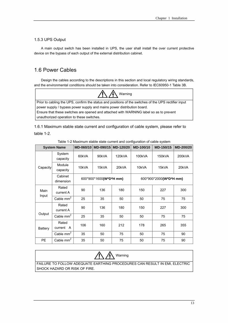
Chapter 1 Installation
13
153 UPS Output
A main output switch has been installed in UPS the user shall install the over current protective
device on the bypass of each output of the external distribution cabinet
16 Power Cables
Design the cables according to the descriptions in this section and local regulatory wiring standards
and the environmental conditions should be taken into consideration Refer to IEC60950-1 Table 3B
Warning
Prior to cabling the UPS confirm the status and positions of the switches of the UPS rectifier input
power supply bypass power supply and mains power distribution board
Ensure that these switches are opened and attached with WARNING label so as to prevent
unauthorized operation to these switches
161 Maximum stable state current and configuration of cable system please refer to
table 1-2
Table 1-2 Maximum stable state current and configuration of cable system
System Name MD-06010 MD-09015 MD-12020 MD-10010 MD-15015 MD-20020
Capacity
System
capacity 60kVA 90kVA 120kVA 100kVA 150kVA 200kVA
Module
capacity 10kVA 15kVA 20kVA 10kVA 15kVA 20kVA
Cabinet
dimension 6009001600(WDH mm) 6009002000(WDH mm)
Main
Input
Rated
current A 90 136 180 150 227 300
Cable mm2 25 35 50 50 75 75
Output
Rated
current A 90 136 180 150 227 300
Cable mm2 25 35 50 50 75 75
Battery
Rated
current A 106 160 212 178 265 355
Cable mm2 35 50 75 50 75 90
PE Cable mm2 35 50 75 50 75 90
Warning
FAILURE TO FOLLOW ADEQUATE EARTHING PROCEDURES CAN RESULT IN EMI ELECTRIC
SHOCK HAZARD OR RISK OF FIRE
Chapter 1 Installation
14
162 Cable Connection
Note
The operations described in this section must be performed by authorized electricians or qualified
technical personnel If you have any difficulties do not hesitate to contact our Customer Service amp
Support department at the address given at the beginning of this manual
After the equipment has been finally positioned and secured connect the power cables as
described in the following procedures
1 Verify that all the external input distribution switches of the UPS are completely opened and the
UPS internal maintenance bypass switch is opened Attach necessary warning signs to these
switches to prevent unauthorized operation
2 Open the back door of the cabinet remove the cover and then the input and output terminal
battery terminal and earth terminal are visible
3 Connect the input earth wire to input earth terminal Please note the earth wire shall be connected
in accordance with related local or state regulation
4 For common bypass and rectifier inputs connect the AC input supply cables to the UPS input
terminals (Main input A-B-C-N) and connect the output loaded cable to the UPS output terminals
(Output A-B-C-N) and tighten the connections to 13 Nm (M8 Bolt) ENSURE CORRECT PHASE
ROTATION
5 Connect the battery cables between the UPS battery terminals and battery switch ENSURE
CORRECT PHASE ROTATION
Warning-Hazardous battery terminal voltage of 400Vdc
Ensure the correct polarity connection between the battery terminals and the UPS terminals Positive
terminal to positive terminal negative terminal to negative terminal and disconnect one or more than
one cable between every two layers of batteries Do not connect the cables and close the battery
circuit breakers before getting the approval from the commissioning engineer
6 Re-install all the protective covers
17 Control and Communication Cabling
As shown in fig 1-12 the front panel of the bypass module will provide dry contact interface
(J2~J10) communication interface (RS232 485 and SNMP card interface) as well as LBS interface
干接点接口
SNMP卡接口
RS485接口
RS232接口LBS接口
Fig 1-12 Dry contact interface and communication interface
Dry contact
interface
SNMP card port
LBS port RS232 port
RS485 port
Chapter 1 Installation
15
The UPS accepts external signal from zero-voltage (dry) contacts connected through external dry
contact terminals produced and phoenix terminals that are in bypass module Through software
programming these signals become active when these contacts connect to +24V to ground)The cables
connected to DRY terminal must be separated from power cables Moreover these cables should be
double insulated with a typical 05 to 15 mm2
cross-section area for a maximum connection length
between 25 and 50 meters
171 Dry Contact Interface of Battery and Environmental Temperature Detection
The input dry contact J2 and J3 can detect the temperature of batteries and environment
respectively which can be used in environment monitoring and battery temperature compensation 1
J2 and J3 interfaces diagram are shown in fig 1-13 the description of interface is in table 1-3
Fig 1-13 Diagram of J2 and J3 dry contact for temperature detecting
Table 1-3 Description of input dry contact interface J2 and J3
Position Name Purpose
J21 TEMP_BAT Battery temperature detection
J22 GND Power ground
J31 TEMP_ENV Environment temperature detection
J32 GND Power ground
Note Specified temperature sensor is required for temperature detection (R25=5Ohm
B2550=3275) please confirm with the manufacturer or contact local maintenance engineers when
placing an order
172 Remote EPO Input Port
The UPS has an Emergency Power OFF (EPO) function This function can be activated by pressing
a button on the control panel of the UPS or through a remote contact provided by the user The EPO
pushbutton is protected by a hinged plastic cover
J4 is the input port for remote EPO It requires shorting NC and +24v during normal operation and
the EPO is triggered when opening NC and +24v or shorting NO and +24v The port diagram is shown in
fig 1-14 and port description is shown in table 1-4
Chapter 1 Installation
16
Fig 1-14 Diagram of input port for remote EPO
Table 1-4 Description of input port for remote EPO
Position Name Purpose
J41 EPO_NC EPO is activated when disconnecting fromJ42
J42 +12V +24V connect the common terminal of NC and NO
J43 +12V EPO is activated when shorting with J42
The EPO is triggered when shorting pin 2 and 3 or opening pin 2 and 1 of J4
If an external emergency stop facility is required it is connected via the reserved terminals of J4
The external emergency stop facility needs to use shielded cables to connect to the normally
openclosed remote stop switch between these two pins If this facility is not used then pin 3 and pin 4 of
J4 must be open or pin 1 and pin 2 of J4 must be shorted
Note
1 The emergency stop action within the UPS will shut down the rectifier inverter and static bypass
However it does not internally disconnect the mains input power supply To disconnect ALL power to
the UPS open the upstream input circuit breaker(s) when the EPO is activated
2 Pin 1 and 2 of J4 have been shorted before the UPS is delivered
173 Generator Input Dry Contact
J5 is status interface for generator connection Connect pin 2 of J5 with + 24 power supply it
indicates that the generator has been connected with the system The interface diagram is shown in fig
1-15 and interface description is shown in table 1-5
Chapter 1 Installation
17
Fig 1-15 Diagram of status interface and connection of generator
Table 1-5 Description of maintenance bypass switch and output switch status interface
Position Name Purpose
J51 +24V +24V power supply
J52 GEN Connection status of generator
J53 GND Power ground
174 BCB Input Port
J6 and J7 are the ports of BCB The port diagram is shown in fig 1-16 and description is shown in
table 1-6
BC
B_D
RV
BC
B_C
ON
T
J6 J7
BC
B_O
NL
+24V+24V
+24V
Fig 1-16 BCB Port
Table 1-6 Description of BCB port
Position Name Description
J61 BCB_DRV BCB actuating signal provide the actuating signal of +18V 20mA
J62 BCB_CONT BCB contact status connect with the normally open signal of BCB
J71 GND Power ground
J72 BCB_ONL BCB on-linendashinput (normally open) BCB is on-line when the signal
is connecting with GND
175 Battery Warning Output Dry Contact Interface
J8 is the output dry contact interface which outputs the battery warnings of low or excessive
voltage when the battery voltage is lower than set value an auxiliary dry contact signal will be
provided via the isolation of a relay The interface diagram is shown in fig 1-17 and description is
shown in table 1-7
Generator
Chapter 1 Installation
18
Fig 1-17 Battery warning dry contact interface diagram
Table 1-7 Battery warning dry contact interface description Position Name Purpose
J81 BAT_LOW_NC Battery warning relay (normally closed) will be open during warning
J82 BAT_LOW_NO Battery warning relay (normally open) will be closed during warning
J83 GND Center of battery warning relay
176 Integrated Warning Output Dry Contact Interface
J9 is the integrated warning output dry contact interface when one or more than one preset
warning is triggered the system will send an integrated warning information and provide an auxiliary
dry contact signal via the isolation of a relay The interface diagram is shown in fig 1-18 and description
is shown in table 1-8
Fig 1-18 Integrated warning dry contact interface diagram
Table 1-8 Integrated warning dry contact interface description Position Name Purpose
J91 ALARM_NC Integrated warning relay (normally closed) will be open during warning
J92 ALARM_NO Integrated warning relay (normally open) will be closed during warning
J93 GND Centre of integrated warning relay
177 Mains Failure Warning Output Dry Contact Interface
J10 is the output dry contact interface for mains failure warning when the mains fails the system
will send a mains failure warning information and provide an auxiliary dry contact signal via the isolation
of a relay The interface diagram is shown in fig 1-19 and description is shown in table 1-9
Chapter 1 Installation
19
Fig 1-19 Mains failure warning dry contact interface diagram
Table 1-9 Mains failure warning dry contact interface description Position Name Purpose
J91 UTI_FAIL_NC Mains failure warning relay(normally closed) will be open during
warning
J92 UTI_FAIL_NO Mains failure warning relay normally open) will be closed during
warning
J93 GND Centre of mains failure warning relay
178 RS232 Port and SNMP Card Port
RS232 and RS485 Port provide serial data which can be used for commissioning and maintenance
by authorized engineers or maintainers or can be used for networking or integrated monitoring system in
the service room
SNMP Card Port used for field installation of the communication option card(SNMP card)
179 LBS (Load Bus Synchronizer) Port
The dual bus system (DBS) consists of two independent UPS rack module systems as shown in fig
1-20 The dual bus system is configured for high availability and is suitable for powering the load with
dual inputs If the load is single-input load the static transfer switch and LBS control is recommended to
maintain both UPS outputs synchronized for uninterrupted transfers Please install the system according
to the installation descriptions for different system configurations
The dual bus system is supported by UPS it requires connecting the LBS signal cables of two UPS
when constructing the dual bus system please refer to relevant chapter for detailed configuration and
installation and the system software shall be configured as required
UPS 1
LBS
监控旁路模块 UPS 2
LBS
监控旁路模块
Fig 1-20 LBS Connection Diagram
18 Installation Drawing
Please refer to fig 1-21 fig 1-22 fig 1-23 and fig 1-24
UPS 1 monitoring bypass module
UPS 2 monitoring bypass module
Chapter 1 Installation
20
Fig 1-21 Installation Diagram
Chapter 1 Installation
21
顶视图
2m cabinet front view
16 m cabinet (front view)
Fig 1-22 UPS front view (Unit mm)
Top view
Chapter 1 Installation
22
A
2m cabinet
A
16m cabinet
Fig 1-23 UPS back view
Chapter 1 Installation
23
A
A处放大
Fig 1-24 UPS front view
Amplification of A
24 Chapter 2 Operations
24
Chapter 2 Operations
This chapter introduces the basic knowledge of UPS operations including working principle
operation mode battery management and protection
Warning Hazardous mains voltage andor battery voltage present(s)behind the protective cover
The components that can only be accessed by opening the protective cover with tools cannot be
operated by user
Only qualified service personnel are authorized to remove such covers
21 Introduction
UPS provides the critical load (such as communication and data processing equipment) with high
quality uninterruptible AC power The power from UPS is free from voltage and frequency variations and
disturbances (interruption and spike) experienced at the Mains AC input supply
This is achieved through high frequency double conversion power pulse width modulation (PWM)
associated with full digital signal processing control (DSP) which features high reliability and
convenience for use
211 Principle
As shown in fig 2-1 the AC input mains source is supplied at UPS input and converted into a DC
source This DC source feeds the Inverter that converts the DC source into a clean and input
independent AC source The battery powers the load through the inverter in case of an AC input mains
power failure The utility source can also power the load through the static bypass
When the UPS needs maintenance or repair the load can be transferred to maintenance bypass
without interruption and the power module and bypass module can be removed for maintenance
Chapter 2 Operations 25
25
Fig 2-1 System principle framework
212 Bypass Module
The circuit blocks labeled ldquobypass modulerdquo in fig 2-1 contain electronically controlled switching
circuits that enable the critical load to be connected to either the inverter output or to a bypass power
source via the static bypass line During normal system operation the load is connected to the inverter
but in the event of a UPS overload or inverter failure the load is automatically transferred to the static
bypass line
To provide a clean (no-break) load transfer between the inverter output and static bypass line the
inverter output and bypass supply must be fully synchronized during normal operating conditions This is
achieved through the inverter control electronics which makes the inverter frequency track that of the
static bypass supply provided that the bypass remains within an acceptable frequency window
A manually controlled maintenance bypass supply is incorporated into the UPS design It enables
the critical load to be powered from the utility (bypass) supply while the UPS is shut down for routine
maintenance
Note
When the UPS is operating in bypass mode or on maintenance bypass the connected equipment is
not protected from power failures or surges and sags
22 Operation Mode
The MD UPS is an on-line double-conversion reverse-transfer UPS that permits operation in these
modes
Normal mode
26 Chapter 2 Operations
26
Battery mode
Auto-Restart mode
Bypass mode
Maintenance mode (manual bypass)
ECO mode
Frequency converters mode
221 Normal Mode
The UPS inverter power modules continuously supplies the critical AC load The rectifiercharger
derives power from the AC mains input source and supplies DC power to the inverter while
simultaneously FLOAT or BOOST charging its associated backup battery
222 Battery Mode
Upon failure of the AC mains input power the inverter power modules which obtains power from the
battery supplies the critical AC load There is no interruption in power to the critical load upon failure
After restoration of the AC mains input power the ldquoNormal Moderdquo operation will continue automatically
without the necessity of user intervention
Note UPS can also be started through battery (charged) mode via battery cold start function upon
failure of the AC mains Therefore the battery power can be used independently to improve the
utilization rate of UPS
223 Auto-Restart Mode
The battery may become exhausted following an extended AC mains failure The inverter shuts
down when the battery reaches the End of Discharge voltage (EOD) The UPS may be programmed to
ldquoAuto Recovery after EODrdquo after a delay time if the AC mains recovers This mode and any delay time
are programmed by the commissioning engineer
During the process of delay time the battery will be charged by UPS to prevent any risks to load
equipment from future mains failure
224 Bypass Mode
If the inverter overload capacity is exceeded under normal mode or if the inverter becomes
unavailable for any reason the static transfer switch will perform a transfer of the load from the inverter
to the bypass source with no interruption in power to the critical AC load
225 Maintenance Mode
A manual bypass switch is available to ensure continuity of supply to the critical load when the UPS
becomes unavailable eg during a maintenance procedure
Note This manual bypass switch is fitted in all UPS modules Transfer UPS system to bypass
module for power supply first then close maintenance bypass switch Q2 followed by Q1 and Q3
Warning hazard may occur after transferring to maintenance bypass
After UPS being transferred to maintenance bypass power module and bypass module do not work
no display on LCD and input and output terminals as well as N bus are electrically connected
Chapter 2 Operations 27
27
226 ECO Mode
If economical (ECO) mode is selected the double-conversion UPS will stop to work so as to save
energy During the operation of ECO mode the load power will be supplied by bypass preferentially
When bypass power is within the range of normal frequency and voltage load power will be supplied by
bypass or the system will transfer to inverter input followed by load power interruption which extends
within 34 of the utility period Eg when the frequency is 50Hz the interruption time will be less than
15ms when the frequency is 60Hz the time will be less than 125ms
227 Frequency Converters Mode
If the frequency converter configuration is used by UPS it will provide 50Hz or 60Hz stable output
frequency The range of output frequency is 40Hz~70Hz Under this mode static bypass is unavailable
but battery can be selected according to the actual requirements of battery mode
23 Battery Management
231 Normal Function
The following functions should be fitted by commissioning engineers with specified software
1 Constant current boost charging
Current can be set up
2 Constant voltage boost charging
Voltage of boost charging can be set as required by the type of battery
For Valve Regulated Lead Acid (VRLA) batteries maximum boost charge voltage should not
exceed 24V cell
3 Float charge
Voltage of float charging can be set as required by the type of battery
For VRLA float charge voltage should be between 22V to 23V
4 Float charge temperature compensation (optional)
A coefficient of temperature compensation can be set as required by the type of battery
5 End of discharge (EOD) protection
If the battery voltage is lower than the EOD the battery converter will shut down and the battery is
isolated to avoid further battery discharge EOD is adjustable from 16V to 175V per cell (VRLA) or 09
to 11 V per cell
6 Battery low warning time
It is adjustable between 3 and 60 minutes The default is 5 minutes
232 Advanced Functions (Battery Self-checking and Maintenance)
At periodic intervals 20 of the rated capacity of the battery will be discharged automatically and
the actual load must exceed 20 of the rated UPS (KVA) capacity If the load is less than 20
auto-discharge cannot be executed The periodic interval can be set from 30 to 360 days The battery
self-test can be disabled
ConditionsmdashBattery at float charge for at least 5 hours load equal to 20~100 of rated UPS capacity
TriggermdashManually through the command of ldquoBattery Maintenance Testrdquo in LCD panel or automatically
Battery Self-Test Intervalmdash30-360 days (default setting is battery self-test disabled)
28 Chapter 2 Operations
28
24 Battery Protection
The following functions should be fitted by commissioning engineers with specified software
1 Battery Low Pre-warning
The battery under voltage pre-warning occurs before the end of discharge After this pre-warning
the battery should have the capacity for 3 remaining minutes discharging with full load The time is user
configured from 3 to 60 minutes
2 Battery discharge (EOD)off protection
If the battery voltage is lower than the EOD the battery converter will be shut down EOD is
adjustable from 16V to 175V per cell (VRLA) or 09 to 11 V per cell (NiCd)
3 Battery Circuit Breaker (BCB) Alarm
The alarm occurs when the battery disconnect device disconnects The external battery connects to
the UPS through the external battery circuit breaker The circuit breaker is manually closed and tripped
by the UPS control circuit
Chapter 3 Operation Instructions 29
29
Chapter 3 Operating Steps
This chapter describes UPS operation instructions in detail
All functional keys and LED display involved in operation instructions please refer to chapter 4
During operation the buzzer alarm may occur at any time Select ldquomuterdquo on LED to muffle the audible
alarm
Warning-Hazardous mains voltage andor battery voltage present(s)behind the protective cover
1 The components that can only be accessed by opening the protective cover with tools cannot be
operated by user
2 Only qualified service personnel are authorized to remove such covers
31 Power Switches
As shown in fig 3-1 open the front door of UPS the power switch is visible which includes input
switch output switch and maintenance bypass switch (with anti-misoperation stop plate)
输入开关 输出开关
维修旁路开关
Fig 3-1 Power switch location diagram
32 UPS Start-up
The UPS system only has a maintenance bypass isolating switch and all the other transfers are
processed automatically by internal control logics
Input switch Output switch
Maintenance bypass switch
30 Chapter 3 Operating Instructions
30
321 Normal Module Start
This procedure must be followed when turning on the UPS from a fully powered down condition
The operating procedures are as follows
Warning
This procedure results in mains voltage being applied to the UPS output terminals If any load
equipment is connected to the UPS output terminals please check with the load user that it is safe to
apply power If the load is not ready to receive power then ensure that it is safely to close the output
switch of external distribution cabinet
1 Close UPS output switch and input switch in turns
The LCD starts up at this time The Rectifier indicator flashes during the startup of rectifier The
rectifier enters normal operation state and after about 30s the rectifier indicator goes steady green After
initialization the bypass static switch closes The UPS Mimic LEDs will indicate as shown in table 3-1
Table 3-1 Indicator status
LED Status
Rectifier indicator Green
Battery indicator Red
Bypass indicator Green
Inverter indicator Off
Load indicator Green
Status indicator Green
Note
The output circuit breaker must be closed first followed by input circuit breaker or the rectifier cannot
be started and alarm ldquorectifier failurerdquo
The inverter starts up at this time the inverter indicator flashes After the rectifier enters normal
operation state UPS power supply will transfer from bypass to inverter then the bypass indicator turns
off and load indicator lights The status of indicators is shown in table 3-2
Table 3-2 Indicator Status
LED Status
Rectifier indicator Green
Battery indicator Red
Bypass indicator Off
Inverter indicator Green
Load indicator Green
Status indicator Green
Close external battery switch again battery indicator turns off a few minutes later the battery will be
charged by UPS which will enter normal mode operation The indicator status is shown in table 3-3
Table 3-3 Indicator status
LED Status
Rectifier indicator Green
Battery indicator Green
Bypass indicator Off
Inverter indicator Green
Load indicator Green
Status indicator Green
322 Operating steps of Battery cold Start
1 Check if the batteries have been connected close the external battery switch
Chapter 3 Operation Instructions 31
31
2 Press the red start-up button of battery under the rectifier input circuit breaker for 3 seconds (see fig
3-2)
The LCD starts up at this time The green battery indicator flashes The rectifier enters normal
operation states and after about 30s the battery indicator goes steady green
3 The inverter starts up automatically the green inverter indicator flashes The output of inverter
appears after 60s The UPS works on battery mode
32 Chapter 3 Operating Instructions
32
电池启动按钮
Fig 3-2 Position diagram of battery startup button
Battery startup button
Chapter 3 Operation Instructions 33
33
33 Procedure for Switching between Operation Modes
331 Procedure for Switching the UPS into Battery mode from Normal Mode
Open input switch to cut off the mains UPS enters the battery mode If UPS should be switched to
normal mode wait for a few seconds before close input switch so as to supply the mains again 10s
later the rectifier will start up automatically to supply power to the inverter
332 Procedure for Switching the UPS into Bypass mode from Normal Mode
Select ldquoTran Byprdquo on the LCD or press ldquooffrdquo buttons of each power module in turn
Note
In bypass mode the load is directly fed by the mains power instead of the pure AC power from the
inverter
333 Procedure for Switching the UPS into Normal from Bypass Mode
Select exit bypass mode on the LCD
334 Procedure for Switching the UPS into a Maintenance Bypass from Normal Mode
In normal operation this operation instruction will switch the load from inverter input to maintenance
bypass
Caution
Before making this operation read messages on display to be sure that bypass supply is regular and
the inverter is synchronous with it so as not to have a risk of a short interruption in powering the load
1 Press ldquoTran Byprdquo on the LCD or press ldquooffrdquo on each power module in turns
If press rdquoTran Byprdquo on the LCD the inverter indicator will flash green and the buzzer will alarm
If press ldquooffrdquo on each power module in turns the inverter indicator will go off and the buzzer will
alarm
The load will be transferred to static bypass and the inverter is closed
2 Close maintenance bypass switch Q2 the load power will be supplied by maintenance bypass and
then open the inverter circuit breaker Q1 output switch Q3 and battery switch
Warning
If you need to maintain the module wait for 10 minutes to let the DC bus capacitor fully discharge
before removing corresponding module
335 Procedure for Switching the UPS into Normal from a Maintenance Bypass Mode
This procedure can transfer the load to normal main mode when the UPS is operating under the
maintenance bypass mode
1 Close output switch Q3 and main switch Q1
The bypass indicator goes green and the load power will be supplied by bypass and maintenance
bypass
2 Open maintenance bypass switch Q2
34 Chapter 3 Operating Instructions
34
The load power is supplied by bypass In the meantime the rectifier starts up rectifier indicator goes
green 30s later at this time the inverter will start up automatically and transfer to inverter mode 1 min
later automatically
3 Close external battery switch the battery indicator goes off Check if the battery voltage on LCD
display is normal
34 Procedure for Completely Powering down a UPS
If you need to power down the UPS completely follow the procedures in section 334 to transfer the
UPS from normal mode to maintenance bypass mode
If you need to isolate the UPS from the AC power supply you should open the external input switch
35 EPO Procedure
The EPO button on UPS operator control and display panel is designed to switch off the UPS in
emergency conditions (eg fire flood etc)To achieve this just press the EPO button and the system
will turn off the rectifier inverter and stop powering the load immediately (including the inverter and
bypass output) and the battery stops charging or discharging
If the input utility is present the UPS control circuit will remain active however the output will be
turned off To completely isolate the UPS you need to open the external mains input supply to the UPS
rack
36 Language Selection
The LCD is available in two languages Chinese English and Korean
The language can be selected through LCD prompt window
37 Control Password
When the LCD displays ldquoinput control password 1rdquo the initial password is 12345678
Chapter 4 Operator Control and Display Panel 35
35
Chapter 4 Operator Control and Display Panel
This chapter introduces the functions and operation instructions of the parts on UPS operator control
and display panel in detail and provides LCD display information including LCD display types detailed
menu information prompt window information and UPS alarm list
41 Introduction
The operator control and display panel is located on the front panel of the UPS Through this LCD
panel the operator can operate and control the UPS and check all measured parameters UPS and
battery status and event and alarm logs The operator control panel is divided into three functional areas
as shown in fig 4-1 mimic current path LCD display amp Menu keys and Control and Operation Keys The
detailed description of parts on operator control and display panel is shown in table 4-1
Fig 4-1 UPS operator control and display panel
Table 4-1 Description of UPS operator control and display panel
Part No Function Button Function
REC Rectifier indicator EPO EPO switch
BAT Battery indicator TAB switch
BYP Bypass indicator ENTER confirm
INV Inverter indicator ESC exit
OUTPUT Load indicator
STATUS Status indicator
36 Chapter 4 Operator Control and Display Panel
36
411 LED Indicator
The LEDs shown on the mini current path represent the various UPS power paths and show the
current UPS operating status The status description of indicators is shown in table 4-2
Table 4-2 Status description of indicator
Indicator State Purpose
Rectifier
indicator
Steady green Rectifier normal for all modules
Flashing green Rectifier for at least on module normal mains normal
Steady red Rectifier fault
Flashing red Mains abnormal for at least one module
Off Rectifier not operating
Battery
indicator
Steady green Battery charging
Flashing green Battery discharging
Steady red
Battery abnormal (battery failure no battery or battery reverse) or
battery converter abnormal (failure over current or over temperature)
EOD
Flashing red Battery low voltage
Off Battery and battery converter normal battery not charging
Bypass
indicator
Steady green Load power supplied by bypass
Steady red Bypass power abnormal or out of normal range or static bypass
switch fault
Flashing red Bypass voltage abnormal
Off Bypass normal
Inverter
indicator
Steady green Load power supplied by inverter
Flashing green Inverter On start synchronization of standby (ECO mode) for at least
one module
Steady red System power not supplied by inverter inverter fault for at least one
module
Flashing red System power supplied by inverter inverter fault for at least one
module
Off Inverter not operating for all modules
Load
indicator
Steady green UPS output ON and normal
Steady red UPS output overload and overtime or output short or output no power
supply
Flashing red Overload output of UPS
Off No output of UPS
Status
indicator
Steady green Normal operation
Steady red Failure
412 Audible Alarm (buzzer)
There are two different types of audible alarm during UPS operation as shown in table 4-3
Table 4-3 description of audible alarm
Alarm Purpose
Two short alarm with
a long one
when system has general alarm (for example AC fault) this audible alarm
can be heard
Continuous alarm When system has serious faults (for example fuse or hardware fault) this
audible alarm can be heard
Chapter 4 Operator Control and Display Panel 37
37
413 Functional Keys
There are 4 functional keys on operator control and display panel which are used together with LCD
The functions description is shown in table 4-4
Table 4-4 Functions of functional keys
Functional key Functions
EPO switch To cut off the load power to shut down the rectifier inverter static
bypass and battery
TAB switch
ENTER confirm
ESC exit
42 LCD Display Type
Following the self-check of UPS LCD display the main LCD display is shown as fig 4-2 which can
be divided into three display windows system information data command and current record
Fig 4-2 Main LCD display
The description of LCD icon is shown in table 4-5
Table 4-5 Description of LCD icons
Icon Description
Bypass parameter
UPS system
information
window
Data
command
window
Current
record
window
38 Chapter 4 Operator Control and Display Panel
38
Icon Description
Main input parameter
History file system information
Function setting (display calibration password setting time setting date format
communication protocol and language setting) system setting (used by product
maintainers)
Battery data battery parameter setting (used by service staff)
Test (battery self-test battery maintenance)
Functional keys used by service staff (fault clearing history file clearing noise
clearing manual switch of bypass) userrsquos setting (system mode machine
number system ID output voltage adjustment frequency tracing speed
frequency tracing limit)
Output parameter
Load
Noise clearing noise clearing cancel
Log view page updown
Select a icon on LCD as shown in fig 4-3 to view the UPS parameter represented by this icon eg
select the LCD will display the data of system main input
Chapter 4 Operator Control and Display Panel 39
39
Fig 4-3 Select data
Or select and confirm a module as shown in fig 4-4 the LCD will display the
operating status of this module
Fig 4-4 Select a module
40 Chapter 4 Operator Control and Display Panel
40
Select in the operating status of a module to view the main input data of this module
Select in the operating status of a module to view the main output data of this module
Select in the operating status of a module to view the load data of this module
Select in the operating status of a module to view the maintenance code and module
software code of this module
Select to return to the previous page
Select to return to the home page
Default display
During the operation of system if therersquos no alarm in 2 min the system will display default After a
short delay the backlight of LCD display goes off press any key to reactivate the display
43 Detailed Description of Menu Items
The LCD main display shown in fig 4-2 is described in details below
UPS information window
UPS information window display the current time and UPS name The information of the window is
not necessary for the user to operate The information of this window is given in table 4-6
Table 4-6 Description of items in UPS system information window
Display contents Meaning
MD12020 UPS Name
1200 Current Time (format 24 hours hours minute)
UPS menu and data window
UPS menu window displays the menu name of data window while the data window displays the
related contents of selected menu in menu window Select UPS menu and data window to browse
related parameters of UPS and set related functions The details are given in table 4-7
Table 4-7 Item description of UPS menu and data window
Menu name Menu item Meaning
Main input
V phase(V) V phase
I phase(A) I phase
Freq(Hz) Input frequency
PF Power factor
Bypass input
V phase(V) V phase
Freq (Hz) Bypass frequency
I phase(A) I phase
PF Power factor
AC output
V phase(V) V phase
I phase(A) I phase
Freq (Hz) Output frequency
PF Power factor
This UPS Sout (kVA) Sout Apparent Power
Chapter 4 Operator Control and Display Panel 41
41
Menu name Menu item Meaning
modulersquos
load
Pout (kW) Pout Active Power
Qout (kVAR) Qout Reactive Power
Load () Load (The percentage of the UPS rating load)
Battery data
Environmental
Temp Environmental Temp
Battery
voltage(V) Battery bus voltage
Battery current
A) Battery bus current
Battery
Temp() Battery Temp
Remaining Time
(Min) Remaining battery backup time
Battery capacity
() The percentage compared with new battery capacity
battery
equalized
charging
Battery is equalized charging
battery float
charging Battery is float charging
Battery
disconnected Battery is not connected
Current
record (current alarm)
Display all current alarm The alarm list displayed on LCD of
UPS operator control and display panel please refer to table 4-9
History
record (history alarm)
Display all history alarm The alarm list displayed on LCD of
UPS operator control and display panel please refer to table 4-9
Menu
Language
(language
option) 2 languages can be selected
Settings
Display
calibration Adjust the accuracy of LCD display
Date format set MM DD YYYY and YYYY MM DD formats can be selected
Date amp Time DateTime set
Language set User can set the language (Chinese and English)
Communication
mode
Set communication mode MODBUS Power protocol and
company custom protocol modes can be selected Power
protocol mode can be divided into equipment address baud
rate set MODBUS protocol mode can be divided into
communication mode (RTUASCⅡ) equipment address
baud rate and check-bit set Company custom protocol mode
is the customed protocol of the company no option is
available
Control
password set User can modify control password 1
Test
Command
(Battery Test
Control
Battery
maintenance
test
This test will lead to the battery being partly discharged to
activate battery at the same time the approximate battery
capacity will be obtained Bypass must be in normal condition
the battery capacity should be above 25
42 Chapter 4 Operator Control and Display Panel
42
Menu name Menu item Meaning
Battery
self-check test
UPS switches to battery discharge for discharging to test if the
battery is normal Bypass must be in normal condition the
battery capacity should be above 25
Stop testing Manually Stop the test including maintenance test capacity test
UPS system
information
Monitoring
software version Provide monitoring software version
Rectified
software version Provide rectified software version
Inverted
software version Provide inverted software version
Serial No The serial no set when delivery from the factory
Rated
information Network setting of system operating
Module type Type of the module
44 Alarm List
The follow table 4-8 gives the complete list of all the UPS events displayed by history record window
and current record window
Table 4-8 Alarm List
Alarm Explanation
UPS power supply The system is in normal inverted power supply status
Bypass power
supply The system is in bypass power supply status
No power supply System no output
Battery equalized
charging Battery is in boost charging
Battery float
charging Battery is in float charging
Battery discharging The system is operating in battery discharging status
Battery connected Battery is connected
Battery
disconnected Battery is not connected
Maintenance circuit
breaker close Maintenance circuit breaker is close
Maintenance circuit
breaker open Maintenance circuit breaker is open
Emergency
shutdown System emergency shutdownEPO
Generator
connected External generator is connected
Mains abnormal Input mains abnormal
Bypass phase
conversion Bypass input phase converse
Bypass voltage
abnormal Bypass input voltage abnormal
Bypass fault Bypass fault
Bypass overload Bypass output is overload
Up to bypass
overtime of Bypass is overtime of overload
Chapter 4 Operator Control and Display Panel 43
43
Alarm Explanation
overload
Bypass frequency
tracing exceeds Bypass frequency is out of the tracing range
Switch times up to
in this hour
The times of switch between bypass and inverter exceeds 5 times in the latest
hour
Output short System output short
Battery EOD Battery voltage achieves shutdown point
Battery self-check The system enters battery self-check mode
Battery self-check
success Battery normal during system self-check
Battery manual
check failure Battery fault during system self-check
Battery
maintenance The system is in battery maintenance status
Battery
maintenance
success
Battery maintenance status completes
Battery
maintenance failure Battery maintenance process is not normal
Stop testing Battery self-check or battery maintenance status stops
Fault clearing Clear the alarmed fault
Delete history
record Delete all history record
N communication
node connected N module is connected to UPS system
N communication
node disconnected N module is not connected to UPS system
N rectifier fault N module rectifier fault
N inverter fault N module inverter fault
N rectifier
overheat N module rectifier overheat
N fan fault N module fan fault
N output overload N module output overload
N overtime of
overload N module output overtime of overload
N inverter
overheat N module inverter overheat
Inverter power
supply ban Inverter power ban supply
Manual switch of
bypass Switch the system to bypass output manually
Cancel manual
switch of bypass Switch the system from bypass to inverter output manually
Battery low voltage Battery low voltage
Battery reversal Battery polarity reversal
N inverter
protection N module inverter protection
Input N line
disconnected System input N line is not connected
Bypass fan fault Bypass module fan fault
N manual N module manual power off
44 Chapter 4 Operator Control and Display Panel
44
Alarm Explanation
shutdown
Chapter 5 Maintenance 45
45
Chapter 5 Installation of Parallel Operation System
The parallel operation system is installed as required by the installation procedures of the single
system and this chapter
The single devices are put parallel and connected as shown in fig 5-1 and the difference between
the lengths of the output cables of the single devices is not more than 10m It is recommended to use an
external bypass cabinet to facilitate maintenance and system testing
Fig 5-1 Typical 1+N parallel operation system
Note when the load exceeds is the capacity of the single device the maintenance bypass
switch CB3 must be removed
The cables for the parallel operation provide double insulation shielding up to 30m long the control
cables for the parallel operation must be connected with all single devices to form a closed loop as
shown in fig5-2
Other power supplies
Rectifier
Charger Inverter Inverter
Output power supply
Load connected
Mains power input L1 L2 L3 N terminal
Mains power inputL1 L2 L3 N terminal
Rectifier
Charger
46 Chapter 5 Maintenance
46
Fig5-2 parallel cables
Chapter 5 Maintenance 47
47
Chapter 6 Maintenance
This chapter introduces UPS maintenance including the maintenance instructions of power module
monitoring bypass module and the change method of dust filter
61 Instruction to Power Bypass and Output Power Distribution
Module
611 Precautions
1 Only maintaining engineers can maintain the power module and monitoring bypass module
2 In principle the power module and bypass module should be disassembled from top to bottom so
as to prevent any inclination from high gravity centre of the cabinet
3 To ensure the safety before maintaining power module and bypass module be sure to use a
multimeter to measure the DC bus capacitor voltage and ensure the voltage is below 60V before
operation and use a multimeter to measure the voltage between operating parts and the earth to
ensure the voltage is lower than hazardous voltage ie DC voltage is lower than 60Vdc and AC
maximum Voltage is lower than 424Vac
4 Bypass module doesnrsquot support any hot insertion and extraction only when UPS is in maintenance
bypass mode or UPS is completely power off can the bypass module be disassembled
5 The module can be maintained 10 mins after extracting power module and bypass module which
can be inserted into the cabinet 10 mins later
612 Instruction to Power Module
Suppose UPS were in normal mode and bypass were normal a module shall be maintained at
first
1 Press OFF of the module with a pin point or other tiny matter the module will shut down
automatically and exit the system
Note ensure if the remaining module will be overload when exiting a module If therersquos any risk of
overload transfer the whole UPS system to bypass followed by other operations
2 Take off the fixing bolt on the two sides of front and back plate of power module 10 mins later
extract the module from the cabinet
3 After maintaining the module push the module into the equipment cabinet (the interval between
two modules shall be more than 10s) fix the screw on the two sides Then the module will be
connected to UPS system automatically
613 Instruction to Bypass Module
Suppose UPS were in normal mode and the bypass were normal
1 Select LCD touch screen manual switch of bypass the UPS power will be supplied by bypass
2 Close maintenance bypass switch the UPS power will be supplied by maintenance bypass
3 Open UPS output switch and input switch
4 Open external battery switch
48 Chapter 5 Maintenance
48
5 Take off the fixing bolt at the two sides of front board of bypass module extract the front cable
assembly of the module and extract the module from the cabinet
6 After maintaining the module insert the module into the cabinet tighten the screw at the two sides
and connect the front cable assembly of manufacturerrsquos module
7 Close UPS output switch and input switch in turn
2 mins later bypass indicator on the operator control and display panel lights on which indicates
the normal power supply of bypass
8 Open maintenance bypass switch the inverter starts automatically 60s later the UPS will transfer
to normal mode
62 Replacing Dust Screen (optional)
As shown in fig 5-1 there are 3~4 dust filters on the back of UPSrsquo front door each screen is held in
place by a bracket on either side of each filter The procedure of replacing each filter is as follows
1 Open the UPSrsquo front door and locate the filters on the back side of the front door
2 Remove one bracket
3 Remove the dust screen to be replaced and insert the clean one
4 Reinstall the bracket
防尘网固定条
Fig 5-1 Dust screen on the back side of UPS front door
Bracket
Dust screen
Appendix 2 Toxic or Hazardous Materials or Elements Identification Table 49
49
Chapter 7 Product Specification
This chapter provides UPS product specification
71 Applicable Standards
The UPS has been designed to conform to the following European and international standards
Table 6-1 Compliance with European and International Standards
Item Normative reference
General safety requirements for UPS
used in operator access areas EN50091-1-1IEC62040-1-1AS 62040-1-1
Electromagnetic compatibility (EMC)
requirements for UPS EN50091-2IEC62040-2AS 62040-2(C3)
Method of specifying the performance
and test requirements of UPS EN50091-3IEC62040-3AS 62040-3(VFI SS 111)
Note The above mentioned product standards incorporate relevant compliance clauses with generic
IEC and EN standards for safety (IECENAS60950) electromagnetic emission and immunity
(IECEN AS61000 series) and construction (IECENAS60146 series and 60950)
72 Environmental Characteristics
Table 6-2 Environmental Properties
Items Unit Requirements
Acoustic noise level at 1
meter dB 550
Altitude of Operation m le1000m above sea level derate power by 1 per 100m
between 1000m and 2000m
Relative Humidity RH 0 to 95 non condensing
Operating Temperature 0 to 40 deg Battery life is halved for every 10degC increase
above 20degC
UPS Storage-Transport
Temperature -20~70
Recommended Battery
Storage Temperature -20~30 (20degC for optimum battery storage)
73 Mechanical Characteristics
Table 6-3 Mechanical Properties
Cabinet Specification Unit MD6010 MD9015
MD12020
MD10010 MD15015
MD20020
Mechanical Dimension
WtimesDtimesH mm 600times900times1600 600times900times2000
Weight kg 151 182
Color NA Black
Protection Level
IEC(60529) NA IP20
50 Chapter 5 Maintenance
50
Module type Unit MU10 MU15 MU20
Mechanical Dimension
WtimesDtimesH mm 440times590times134
Weight kg 21 22 22
Color NA Black
74 Electrical Characteristics (Input Rectifier)
Table 6-4 Rectifier AC input (mains)
Items Unit Parameter
Rated AC Input
Voltage Vac
380400415(three-phase and sharing neutral with the
bypass input)
Input voltage range Vac -40~+25
Frequency2 Hz 5060(range 40Hz~70Hz)
Power factor kWkVA full load 099
THD THDI 3
75 Electrical Characteristics (Intermediate DC Link)
Table 6-5 Battery
Items Unit Parameters
Battery bus
voltage Vdc Nominal plusmn240V one-side range 198V~288V
Quantity of
lead-acid cells Nominal 40=[1 battery(12V) ] 240=[1 battery(2V) ]
Float charge
voltage Vcell(VRLA)
225Vcell(selectable from 22Vcell~235Vcell)
Constant current and constant voltage charge mode
Temperature
compensation mVcl -30(selectable from 0~-50 25 or 30 or inhibit)
Ripple voltage V float le1
Ripple current C10 le5
equalized
charge voltage VRLA
24Vcell(selectable from 230Vcell~245Vcell)
Constant current and constant voltage charge mode
final
discharging
voltage
Vcell(VRLA)
165Vcell(selectable from 160Vcell ~ 1750Vcell) 06C
discharge current
175Vcell (selectable from 165Vcell ~ 18Vcell) 015C
discharge current
(EOD voltage changes linearly within the set range according to
discharge current)
Battery Charge Vcell 24Vcell(selectable from 23Vcell~245Vcell)
Constant current and constant voltage charge mode
Battery
Charging Power
Max Current
kW 10 UPS capacity (selectable from 0~20 UPS capacity)
Appendix 2 Toxic or Hazardous Materials or Elements Identification Table 51
51
76 Electrical Characteristics (Inverter Output)
Table 6-6 Inverter Output (to important load)
Rated
capacity(kVA) Unit 10~200
Rated AC voltage1 Vac 380400415(three-phase four-wire and sharing neutral with the
bypass)
Freqency2 Hz 5060
overload
110 load 1 hour
125 load 10min
150 load 1min
>150 load 200ms
Fault current 340 short current limitation for 200ms
Non linear load
capability 3 100
Neutral current
capability 170
Steady state
voltage stability
plusmn1(balanced load)
plusmn15(100 imbalance load)
Transient voltage
response 4 plusmn5
THD <15(linear load) <5(non linear load3)
Synchronization -
Window Rated frequency plusmn2Hz(selectable plusmn1~plusmn5Hz)
Max change rate of
synch frequency Hzs 1 selectable 01~5
Inverter voltage
range V(ac) plusmn5
Note
1 Factory setting is 380V Commissioning engineers can set to 400V or 415V
2 Factory setting is 50Hz Commissioning engineers can set to 60Hz
3 EN50091-3(1458) peak value factor is 3 1
4 IEC62040-3EN50091-3 including 0~100~0 load transient the recovery time is half
circle to within 5 of stable output voltage
52 Chapter 5 Maintenance
52
77 Electrical Characteristics(Bypass Mains Input)
Table 6-7 Bypass Mains Input
Rated
capacity(kVA) Unit 60 90 100 120 150 200
Rated AC
Voltage1 Vac
380400415
three-phase four-wire sharing neutral with the rectifier input and providing neutral
reference for the output
Rated current A
91380V
87400V
83415V
136380V
130400V
124415V
151380V
144400V
138415V
182380V
174400V
166415V
227380V
216400V
207415V
302380V
288400V
276415V
Overload
125 load long term
130 load 1 hour
150 load 6min
1000 load 100ms
Superior
protection
bypass line
NA Thermal-magnetic breaker the capacity is 125 of rated current output
IEC60947-2 curve C
Current rating
of neutral cable A 17timesIn
Frequency2 Hz 5060
Switch time
(between
bypass and
inverter)
ms Synchronized switch le1ms
Bypass voltage
tolerance Vac
Upper limit +10+15or+20 default +20
Lower limit -10 -20 -30 or-40 default-20
(acceptable stable bypass voltage delay 10s)
Bypass
frequency
tolerance
plusmn25 plusmn5 plusmn10 or plusmn20 default plusmn10
Synchronizatio
n-Window Hz Rated frequencyplusmn2Hz (selectable from plusmn05Hz~plusmn5Hz)
Note
1 Factory setting is 400V Commissioning engineers can set to 380V or 415V
2 Factory setting is 50Hz Commissioning engineers can set to 60Hz For example UPS is set to frequency
inverter mode and then bypass status will be neglected
78 Efficiency
Table 6-8 Efficiency Loss and Air Exchange
Rated Efficiency (kVA) Unit 10~200kVA
Normal mode(dual conversion) 95
ECO mode 99
Battery discharging efficiency (DCAC) (battery at nominal voltage 480Vdc and full-rated linear load)
battery mode 95
Appendix 2 Toxic or Hazardous Materials or Elements Identification Table 53
53
Appendix A A Guidebook to Ordering and Selection of MU System
MD series UPS module can be divided into equipment cabinet and power module For the cabinet
lectotype please refer to the description in fig 6-1
Fig 6-1 Cabinet Selection
For single power module type please refers to the description in fig 6-2
Fig 6-2 Power Module Selection
Egg the requirements of a plant room are given below
The maximum power supply of the plant room is 120kVA however it is expected to be expanded to
200kVA in 3-5 years Therefore a 200kVA cabinet and 6 20kVA power module can be purchased to
constitute an uninterrupted 120kVA power system which can be expanded to 200kVA on-line The order
symbol is
1 set MD20020
6 set MU20
Option list
MD-SNMP card remote network monitoring card
MD-1600 dust filter dust screen for 16m cabinet
MD-2000 dust filter dust screen for 2m cabinet
Represents the capacity of a single power module
10 represents 10kVA
15 represents 15kVA
20 represents 20kVA
represents a single power module
Represents UPS system capacitypower module
06010 represents 60kVA10kVA
09015 represents 90kVA15kVA
12020 represents 120kVA20kVA
15015 represents 150kVA15kVA
20020 represents 200kVA20kVA
MD represents UPS cabinet
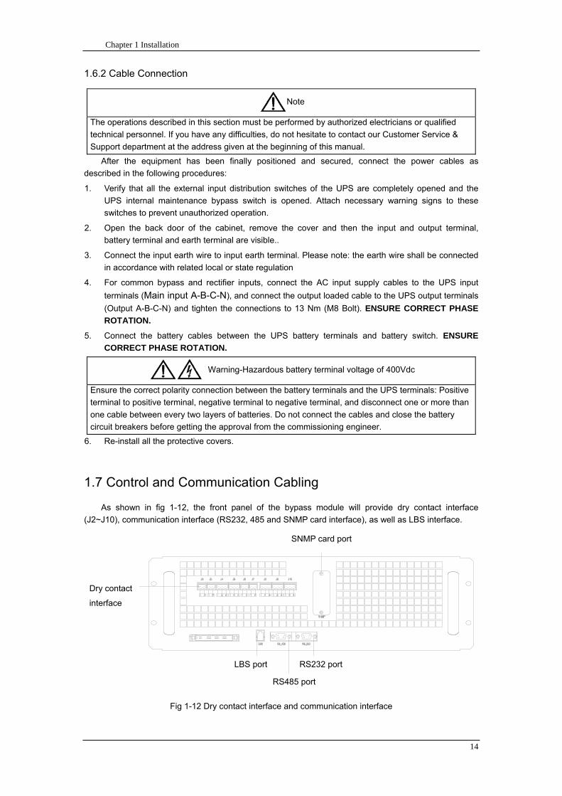
Chapter 1 Installation
14
162 Cable Connection
Note
The operations described in this section must be performed by authorized electricians or qualified
technical personnel If you have any difficulties do not hesitate to contact our Customer Service amp
Support department at the address given at the beginning of this manual
After the equipment has been finally positioned and secured connect the power cables as
described in the following procedures
1 Verify that all the external input distribution switches of the UPS are completely opened and the
UPS internal maintenance bypass switch is opened Attach necessary warning signs to these
switches to prevent unauthorized operation
2 Open the back door of the cabinet remove the cover and then the input and output terminal
battery terminal and earth terminal are visible
3 Connect the input earth wire to input earth terminal Please note the earth wire shall be connected
in accordance with related local or state regulation
4 For common bypass and rectifier inputs connect the AC input supply cables to the UPS input
terminals (Main input A-B-C-N) and connect the output loaded cable to the UPS output terminals
(Output A-B-C-N) and tighten the connections to 13 Nm (M8 Bolt) ENSURE CORRECT PHASE
ROTATION
5 Connect the battery cables between the UPS battery terminals and battery switch ENSURE
CORRECT PHASE ROTATION
Warning-Hazardous battery terminal voltage of 400Vdc
Ensure the correct polarity connection between the battery terminals and the UPS terminals Positive
terminal to positive terminal negative terminal to negative terminal and disconnect one or more than
one cable between every two layers of batteries Do not connect the cables and close the battery
circuit breakers before getting the approval from the commissioning engineer
6 Re-install all the protective covers
17 Control and Communication Cabling
As shown in fig 1-12 the front panel of the bypass module will provide dry contact interface
(J2~J10) communication interface (RS232 485 and SNMP card interface) as well as LBS interface
干接点接口
SNMP卡接口
RS485接口
RS232接口LBS接口
Fig 1-12 Dry contact interface and communication interface
Dry contact
interface
SNMP card port
LBS port RS232 port
RS485 port
Chapter 1 Installation
15
The UPS accepts external signal from zero-voltage (dry) contacts connected through external dry
contact terminals produced and phoenix terminals that are in bypass module Through software
programming these signals become active when these contacts connect to +24V to ground)The cables
connected to DRY terminal must be separated from power cables Moreover these cables should be
double insulated with a typical 05 to 15 mm2
cross-section area for a maximum connection length
between 25 and 50 meters
171 Dry Contact Interface of Battery and Environmental Temperature Detection
The input dry contact J2 and J3 can detect the temperature of batteries and environment
respectively which can be used in environment monitoring and battery temperature compensation 1
J2 and J3 interfaces diagram are shown in fig 1-13 the description of interface is in table 1-3
Fig 1-13 Diagram of J2 and J3 dry contact for temperature detecting
Table 1-3 Description of input dry contact interface J2 and J3
Position Name Purpose
J21 TEMP_BAT Battery temperature detection
J22 GND Power ground
J31 TEMP_ENV Environment temperature detection
J32 GND Power ground
Note Specified temperature sensor is required for temperature detection (R25=5Ohm
B2550=3275) please confirm with the manufacturer or contact local maintenance engineers when
placing an order
172 Remote EPO Input Port
The UPS has an Emergency Power OFF (EPO) function This function can be activated by pressing
a button on the control panel of the UPS or through a remote contact provided by the user The EPO
pushbutton is protected by a hinged plastic cover
J4 is the input port for remote EPO It requires shorting NC and +24v during normal operation and
the EPO is triggered when opening NC and +24v or shorting NO and +24v The port diagram is shown in
fig 1-14 and port description is shown in table 1-4
Chapter 1 Installation
16
Fig 1-14 Diagram of input port for remote EPO
Table 1-4 Description of input port for remote EPO
Position Name Purpose
J41 EPO_NC EPO is activated when disconnecting fromJ42
J42 +12V +24V connect the common terminal of NC and NO
J43 +12V EPO is activated when shorting with J42
The EPO is triggered when shorting pin 2 and 3 or opening pin 2 and 1 of J4
If an external emergency stop facility is required it is connected via the reserved terminals of J4
The external emergency stop facility needs to use shielded cables to connect to the normally
openclosed remote stop switch between these two pins If this facility is not used then pin 3 and pin 4 of
J4 must be open or pin 1 and pin 2 of J4 must be shorted
Note
1 The emergency stop action within the UPS will shut down the rectifier inverter and static bypass
However it does not internally disconnect the mains input power supply To disconnect ALL power to
the UPS open the upstream input circuit breaker(s) when the EPO is activated
2 Pin 1 and 2 of J4 have been shorted before the UPS is delivered
173 Generator Input Dry Contact
J5 is status interface for generator connection Connect pin 2 of J5 with + 24 power supply it
indicates that the generator has been connected with the system The interface diagram is shown in fig
1-15 and interface description is shown in table 1-5
Chapter 1 Installation
17
Fig 1-15 Diagram of status interface and connection of generator
Table 1-5 Description of maintenance bypass switch and output switch status interface
Position Name Purpose
J51 +24V +24V power supply
J52 GEN Connection status of generator
J53 GND Power ground
174 BCB Input Port
J6 and J7 are the ports of BCB The port diagram is shown in fig 1-16 and description is shown in
table 1-6
BC
B_D
RV
BC
B_C
ON
T
J6 J7
BC
B_O
NL
+24V+24V
+24V
Fig 1-16 BCB Port
Table 1-6 Description of BCB port
Position Name Description
J61 BCB_DRV BCB actuating signal provide the actuating signal of +18V 20mA
J62 BCB_CONT BCB contact status connect with the normally open signal of BCB
J71 GND Power ground
J72 BCB_ONL BCB on-linendashinput (normally open) BCB is on-line when the signal
is connecting with GND
175 Battery Warning Output Dry Contact Interface
J8 is the output dry contact interface which outputs the battery warnings of low or excessive
voltage when the battery voltage is lower than set value an auxiliary dry contact signal will be
provided via the isolation of a relay The interface diagram is shown in fig 1-17 and description is
shown in table 1-7
Generator
Chapter 1 Installation
18
Fig 1-17 Battery warning dry contact interface diagram
Table 1-7 Battery warning dry contact interface description Position Name Purpose
J81 BAT_LOW_NC Battery warning relay (normally closed) will be open during warning
J82 BAT_LOW_NO Battery warning relay (normally open) will be closed during warning
J83 GND Center of battery warning relay
176 Integrated Warning Output Dry Contact Interface
J9 is the integrated warning output dry contact interface when one or more than one preset
warning is triggered the system will send an integrated warning information and provide an auxiliary
dry contact signal via the isolation of a relay The interface diagram is shown in fig 1-18 and description
is shown in table 1-8
Fig 1-18 Integrated warning dry contact interface diagram
Table 1-8 Integrated warning dry contact interface description Position Name Purpose
J91 ALARM_NC Integrated warning relay (normally closed) will be open during warning
J92 ALARM_NO Integrated warning relay (normally open) will be closed during warning
J93 GND Centre of integrated warning relay
177 Mains Failure Warning Output Dry Contact Interface
J10 is the output dry contact interface for mains failure warning when the mains fails the system
will send a mains failure warning information and provide an auxiliary dry contact signal via the isolation
of a relay The interface diagram is shown in fig 1-19 and description is shown in table 1-9
Chapter 1 Installation
19
Fig 1-19 Mains failure warning dry contact interface diagram
Table 1-9 Mains failure warning dry contact interface description Position Name Purpose
J91 UTI_FAIL_NC Mains failure warning relay(normally closed) will be open during
warning
J92 UTI_FAIL_NO Mains failure warning relay normally open) will be closed during
warning
J93 GND Centre of mains failure warning relay
178 RS232 Port and SNMP Card Port
RS232 and RS485 Port provide serial data which can be used for commissioning and maintenance
by authorized engineers or maintainers or can be used for networking or integrated monitoring system in
the service room
SNMP Card Port used for field installation of the communication option card(SNMP card)
179 LBS (Load Bus Synchronizer) Port
The dual bus system (DBS) consists of two independent UPS rack module systems as shown in fig
1-20 The dual bus system is configured for high availability and is suitable for powering the load with
dual inputs If the load is single-input load the static transfer switch and LBS control is recommended to
maintain both UPS outputs synchronized for uninterrupted transfers Please install the system according
to the installation descriptions for different system configurations
The dual bus system is supported by UPS it requires connecting the LBS signal cables of two UPS
when constructing the dual bus system please refer to relevant chapter for detailed configuration and
installation and the system software shall be configured as required
UPS 1
LBS
监控旁路模块 UPS 2
LBS
监控旁路模块
Fig 1-20 LBS Connection Diagram
18 Installation Drawing
Please refer to fig 1-21 fig 1-22 fig 1-23 and fig 1-24
UPS 1 monitoring bypass module
UPS 2 monitoring bypass module
Chapter 1 Installation
20
Fig 1-21 Installation Diagram
Chapter 1 Installation
21
顶视图
2m cabinet front view
16 m cabinet (front view)
Fig 1-22 UPS front view (Unit mm)
Top view
Chapter 1 Installation
22
A
2m cabinet
A
16m cabinet
Fig 1-23 UPS back view
Chapter 1 Installation
23
A
A处放大
Fig 1-24 UPS front view
Amplification of A
24 Chapter 2 Operations
24
Chapter 2 Operations
This chapter introduces the basic knowledge of UPS operations including working principle
operation mode battery management and protection
Warning Hazardous mains voltage andor battery voltage present(s)behind the protective cover
The components that can only be accessed by opening the protective cover with tools cannot be
operated by user
Only qualified service personnel are authorized to remove such covers
21 Introduction
UPS provides the critical load (such as communication and data processing equipment) with high
quality uninterruptible AC power The power from UPS is free from voltage and frequency variations and
disturbances (interruption and spike) experienced at the Mains AC input supply
This is achieved through high frequency double conversion power pulse width modulation (PWM)
associated with full digital signal processing control (DSP) which features high reliability and
convenience for use
211 Principle
As shown in fig 2-1 the AC input mains source is supplied at UPS input and converted into a DC
source This DC source feeds the Inverter that converts the DC source into a clean and input
independent AC source The battery powers the load through the inverter in case of an AC input mains
power failure The utility source can also power the load through the static bypass
When the UPS needs maintenance or repair the load can be transferred to maintenance bypass
without interruption and the power module and bypass module can be removed for maintenance
Chapter 2 Operations 25
25
Fig 2-1 System principle framework
212 Bypass Module
The circuit blocks labeled ldquobypass modulerdquo in fig 2-1 contain electronically controlled switching
circuits that enable the critical load to be connected to either the inverter output or to a bypass power
source via the static bypass line During normal system operation the load is connected to the inverter
but in the event of a UPS overload or inverter failure the load is automatically transferred to the static
bypass line
To provide a clean (no-break) load transfer between the inverter output and static bypass line the
inverter output and bypass supply must be fully synchronized during normal operating conditions This is
achieved through the inverter control electronics which makes the inverter frequency track that of the
static bypass supply provided that the bypass remains within an acceptable frequency window
A manually controlled maintenance bypass supply is incorporated into the UPS design It enables
the critical load to be powered from the utility (bypass) supply while the UPS is shut down for routine
maintenance
Note
When the UPS is operating in bypass mode or on maintenance bypass the connected equipment is
not protected from power failures or surges and sags
22 Operation Mode
The MD UPS is an on-line double-conversion reverse-transfer UPS that permits operation in these
modes
Normal mode
26 Chapter 2 Operations
26
Battery mode
Auto-Restart mode
Bypass mode
Maintenance mode (manual bypass)
ECO mode
Frequency converters mode
221 Normal Mode
The UPS inverter power modules continuously supplies the critical AC load The rectifiercharger
derives power from the AC mains input source and supplies DC power to the inverter while
simultaneously FLOAT or BOOST charging its associated backup battery
222 Battery Mode
Upon failure of the AC mains input power the inverter power modules which obtains power from the
battery supplies the critical AC load There is no interruption in power to the critical load upon failure
After restoration of the AC mains input power the ldquoNormal Moderdquo operation will continue automatically
without the necessity of user intervention
Note UPS can also be started through battery (charged) mode via battery cold start function upon
failure of the AC mains Therefore the battery power can be used independently to improve the
utilization rate of UPS
223 Auto-Restart Mode
The battery may become exhausted following an extended AC mains failure The inverter shuts
down when the battery reaches the End of Discharge voltage (EOD) The UPS may be programmed to
ldquoAuto Recovery after EODrdquo after a delay time if the AC mains recovers This mode and any delay time
are programmed by the commissioning engineer
During the process of delay time the battery will be charged by UPS to prevent any risks to load
equipment from future mains failure
224 Bypass Mode
If the inverter overload capacity is exceeded under normal mode or if the inverter becomes
unavailable for any reason the static transfer switch will perform a transfer of the load from the inverter
to the bypass source with no interruption in power to the critical AC load
225 Maintenance Mode
A manual bypass switch is available to ensure continuity of supply to the critical load when the UPS
becomes unavailable eg during a maintenance procedure
Note This manual bypass switch is fitted in all UPS modules Transfer UPS system to bypass
module for power supply first then close maintenance bypass switch Q2 followed by Q1 and Q3
Warning hazard may occur after transferring to maintenance bypass
After UPS being transferred to maintenance bypass power module and bypass module do not work
no display on LCD and input and output terminals as well as N bus are electrically connected
Chapter 2 Operations 27
27
226 ECO Mode
If economical (ECO) mode is selected the double-conversion UPS will stop to work so as to save
energy During the operation of ECO mode the load power will be supplied by bypass preferentially
When bypass power is within the range of normal frequency and voltage load power will be supplied by
bypass or the system will transfer to inverter input followed by load power interruption which extends
within 34 of the utility period Eg when the frequency is 50Hz the interruption time will be less than
15ms when the frequency is 60Hz the time will be less than 125ms
227 Frequency Converters Mode
If the frequency converter configuration is used by UPS it will provide 50Hz or 60Hz stable output
frequency The range of output frequency is 40Hz~70Hz Under this mode static bypass is unavailable
but battery can be selected according to the actual requirements of battery mode
23 Battery Management
231 Normal Function
The following functions should be fitted by commissioning engineers with specified software
1 Constant current boost charging
Current can be set up
2 Constant voltage boost charging
Voltage of boost charging can be set as required by the type of battery
For Valve Regulated Lead Acid (VRLA) batteries maximum boost charge voltage should not
exceed 24V cell
3 Float charge
Voltage of float charging can be set as required by the type of battery
For VRLA float charge voltage should be between 22V to 23V
4 Float charge temperature compensation (optional)
A coefficient of temperature compensation can be set as required by the type of battery
5 End of discharge (EOD) protection
If the battery voltage is lower than the EOD the battery converter will shut down and the battery is
isolated to avoid further battery discharge EOD is adjustable from 16V to 175V per cell (VRLA) or 09
to 11 V per cell
6 Battery low warning time
It is adjustable between 3 and 60 minutes The default is 5 minutes
232 Advanced Functions (Battery Self-checking and Maintenance)
At periodic intervals 20 of the rated capacity of the battery will be discharged automatically and
the actual load must exceed 20 of the rated UPS (KVA) capacity If the load is less than 20
auto-discharge cannot be executed The periodic interval can be set from 30 to 360 days The battery
self-test can be disabled
ConditionsmdashBattery at float charge for at least 5 hours load equal to 20~100 of rated UPS capacity
TriggermdashManually through the command of ldquoBattery Maintenance Testrdquo in LCD panel or automatically
Battery Self-Test Intervalmdash30-360 days (default setting is battery self-test disabled)
28 Chapter 2 Operations
28
24 Battery Protection
The following functions should be fitted by commissioning engineers with specified software
1 Battery Low Pre-warning
The battery under voltage pre-warning occurs before the end of discharge After this pre-warning
the battery should have the capacity for 3 remaining minutes discharging with full load The time is user
configured from 3 to 60 minutes
2 Battery discharge (EOD)off protection
If the battery voltage is lower than the EOD the battery converter will be shut down EOD is
adjustable from 16V to 175V per cell (VRLA) or 09 to 11 V per cell (NiCd)
3 Battery Circuit Breaker (BCB) Alarm
The alarm occurs when the battery disconnect device disconnects The external battery connects to
the UPS through the external battery circuit breaker The circuit breaker is manually closed and tripped
by the UPS control circuit
Chapter 3 Operation Instructions 29
29
Chapter 3 Operating Steps
This chapter describes UPS operation instructions in detail
All functional keys and LED display involved in operation instructions please refer to chapter 4
During operation the buzzer alarm may occur at any time Select ldquomuterdquo on LED to muffle the audible
alarm
Warning-Hazardous mains voltage andor battery voltage present(s)behind the protective cover
1 The components that can only be accessed by opening the protective cover with tools cannot be
operated by user
2 Only qualified service personnel are authorized to remove such covers
31 Power Switches
As shown in fig 3-1 open the front door of UPS the power switch is visible which includes input
switch output switch and maintenance bypass switch (with anti-misoperation stop plate)
输入开关 输出开关
维修旁路开关
Fig 3-1 Power switch location diagram
32 UPS Start-up
The UPS system only has a maintenance bypass isolating switch and all the other transfers are
processed automatically by internal control logics
Input switch Output switch
Maintenance bypass switch
30 Chapter 3 Operating Instructions
30
321 Normal Module Start
This procedure must be followed when turning on the UPS from a fully powered down condition
The operating procedures are as follows
Warning
This procedure results in mains voltage being applied to the UPS output terminals If any load
equipment is connected to the UPS output terminals please check with the load user that it is safe to
apply power If the load is not ready to receive power then ensure that it is safely to close the output
switch of external distribution cabinet
1 Close UPS output switch and input switch in turns
The LCD starts up at this time The Rectifier indicator flashes during the startup of rectifier The
rectifier enters normal operation state and after about 30s the rectifier indicator goes steady green After
initialization the bypass static switch closes The UPS Mimic LEDs will indicate as shown in table 3-1
Table 3-1 Indicator status
LED Status
Rectifier indicator Green
Battery indicator Red
Bypass indicator Green
Inverter indicator Off
Load indicator Green
Status indicator Green
Note
The output circuit breaker must be closed first followed by input circuit breaker or the rectifier cannot
be started and alarm ldquorectifier failurerdquo
The inverter starts up at this time the inverter indicator flashes After the rectifier enters normal
operation state UPS power supply will transfer from bypass to inverter then the bypass indicator turns
off and load indicator lights The status of indicators is shown in table 3-2
Table 3-2 Indicator Status
LED Status
Rectifier indicator Green
Battery indicator Red
Bypass indicator Off
Inverter indicator Green
Load indicator Green
Status indicator Green
Close external battery switch again battery indicator turns off a few minutes later the battery will be
charged by UPS which will enter normal mode operation The indicator status is shown in table 3-3
Table 3-3 Indicator status
LED Status
Rectifier indicator Green
Battery indicator Green
Bypass indicator Off
Inverter indicator Green
Load indicator Green
Status indicator Green
322 Operating steps of Battery cold Start
1 Check if the batteries have been connected close the external battery switch
Chapter 3 Operation Instructions 31
31
2 Press the red start-up button of battery under the rectifier input circuit breaker for 3 seconds (see fig
3-2)
The LCD starts up at this time The green battery indicator flashes The rectifier enters normal
operation states and after about 30s the battery indicator goes steady green
3 The inverter starts up automatically the green inverter indicator flashes The output of inverter
appears after 60s The UPS works on battery mode
32 Chapter 3 Operating Instructions
32
电池启动按钮
Fig 3-2 Position diagram of battery startup button
Battery startup button
Chapter 3 Operation Instructions 33
33
33 Procedure for Switching between Operation Modes
331 Procedure for Switching the UPS into Battery mode from Normal Mode
Open input switch to cut off the mains UPS enters the battery mode If UPS should be switched to
normal mode wait for a few seconds before close input switch so as to supply the mains again 10s
later the rectifier will start up automatically to supply power to the inverter
332 Procedure for Switching the UPS into Bypass mode from Normal Mode
Select ldquoTran Byprdquo on the LCD or press ldquooffrdquo buttons of each power module in turn
Note
In bypass mode the load is directly fed by the mains power instead of the pure AC power from the
inverter
333 Procedure for Switching the UPS into Normal from Bypass Mode
Select exit bypass mode on the LCD
334 Procedure for Switching the UPS into a Maintenance Bypass from Normal Mode
In normal operation this operation instruction will switch the load from inverter input to maintenance
bypass
Caution
Before making this operation read messages on display to be sure that bypass supply is regular and
the inverter is synchronous with it so as not to have a risk of a short interruption in powering the load
1 Press ldquoTran Byprdquo on the LCD or press ldquooffrdquo on each power module in turns
If press rdquoTran Byprdquo on the LCD the inverter indicator will flash green and the buzzer will alarm
If press ldquooffrdquo on each power module in turns the inverter indicator will go off and the buzzer will
alarm
The load will be transferred to static bypass and the inverter is closed
2 Close maintenance bypass switch Q2 the load power will be supplied by maintenance bypass and
then open the inverter circuit breaker Q1 output switch Q3 and battery switch
Warning
If you need to maintain the module wait for 10 minutes to let the DC bus capacitor fully discharge
before removing corresponding module
335 Procedure for Switching the UPS into Normal from a Maintenance Bypass Mode
This procedure can transfer the load to normal main mode when the UPS is operating under the
maintenance bypass mode
1 Close output switch Q3 and main switch Q1
The bypass indicator goes green and the load power will be supplied by bypass and maintenance
bypass
2 Open maintenance bypass switch Q2
34 Chapter 3 Operating Instructions
34
The load power is supplied by bypass In the meantime the rectifier starts up rectifier indicator goes
green 30s later at this time the inverter will start up automatically and transfer to inverter mode 1 min
later automatically
3 Close external battery switch the battery indicator goes off Check if the battery voltage on LCD
display is normal
34 Procedure for Completely Powering down a UPS
If you need to power down the UPS completely follow the procedures in section 334 to transfer the
UPS from normal mode to maintenance bypass mode
If you need to isolate the UPS from the AC power supply you should open the external input switch
35 EPO Procedure
The EPO button on UPS operator control and display panel is designed to switch off the UPS in
emergency conditions (eg fire flood etc)To achieve this just press the EPO button and the system
will turn off the rectifier inverter and stop powering the load immediately (including the inverter and
bypass output) and the battery stops charging or discharging
If the input utility is present the UPS control circuit will remain active however the output will be
turned off To completely isolate the UPS you need to open the external mains input supply to the UPS
rack
36 Language Selection
The LCD is available in two languages Chinese English and Korean
The language can be selected through LCD prompt window
37 Control Password
When the LCD displays ldquoinput control password 1rdquo the initial password is 12345678
Chapter 4 Operator Control and Display Panel 35
35
Chapter 4 Operator Control and Display Panel
This chapter introduces the functions and operation instructions of the parts on UPS operator control
and display panel in detail and provides LCD display information including LCD display types detailed
menu information prompt window information and UPS alarm list
41 Introduction
The operator control and display panel is located on the front panel of the UPS Through this LCD
panel the operator can operate and control the UPS and check all measured parameters UPS and
battery status and event and alarm logs The operator control panel is divided into three functional areas
as shown in fig 4-1 mimic current path LCD display amp Menu keys and Control and Operation Keys The
detailed description of parts on operator control and display panel is shown in table 4-1
Fig 4-1 UPS operator control and display panel
Table 4-1 Description of UPS operator control and display panel
Part No Function Button Function
REC Rectifier indicator EPO EPO switch
BAT Battery indicator TAB switch
BYP Bypass indicator ENTER confirm
INV Inverter indicator ESC exit
OUTPUT Load indicator
STATUS Status indicator
36 Chapter 4 Operator Control and Display Panel
36
411 LED Indicator
The LEDs shown on the mini current path represent the various UPS power paths and show the
current UPS operating status The status description of indicators is shown in table 4-2
Table 4-2 Status description of indicator
Indicator State Purpose
Rectifier
indicator
Steady green Rectifier normal for all modules
Flashing green Rectifier for at least on module normal mains normal
Steady red Rectifier fault
Flashing red Mains abnormal for at least one module
Off Rectifier not operating
Battery
indicator
Steady green Battery charging
Flashing green Battery discharging
Steady red
Battery abnormal (battery failure no battery or battery reverse) or
battery converter abnormal (failure over current or over temperature)
EOD
Flashing red Battery low voltage
Off Battery and battery converter normal battery not charging
Bypass
indicator
Steady green Load power supplied by bypass
Steady red Bypass power abnormal or out of normal range or static bypass
switch fault
Flashing red Bypass voltage abnormal
Off Bypass normal
Inverter
indicator
Steady green Load power supplied by inverter
Flashing green Inverter On start synchronization of standby (ECO mode) for at least
one module
Steady red System power not supplied by inverter inverter fault for at least one
module
Flashing red System power supplied by inverter inverter fault for at least one
module
Off Inverter not operating for all modules
Load
indicator
Steady green UPS output ON and normal
Steady red UPS output overload and overtime or output short or output no power
supply
Flashing red Overload output of UPS
Off No output of UPS
Status
indicator
Steady green Normal operation
Steady red Failure
412 Audible Alarm (buzzer)
There are two different types of audible alarm during UPS operation as shown in table 4-3
Table 4-3 description of audible alarm
Alarm Purpose
Two short alarm with
a long one
when system has general alarm (for example AC fault) this audible alarm
can be heard
Continuous alarm When system has serious faults (for example fuse or hardware fault) this
audible alarm can be heard
Chapter 4 Operator Control and Display Panel 37
37
413 Functional Keys
There are 4 functional keys on operator control and display panel which are used together with LCD
The functions description is shown in table 4-4
Table 4-4 Functions of functional keys
Functional key Functions
EPO switch To cut off the load power to shut down the rectifier inverter static
bypass and battery
TAB switch
ENTER confirm
ESC exit
42 LCD Display Type
Following the self-check of UPS LCD display the main LCD display is shown as fig 4-2 which can
be divided into three display windows system information data command and current record
Fig 4-2 Main LCD display
The description of LCD icon is shown in table 4-5
Table 4-5 Description of LCD icons
Icon Description
Bypass parameter
UPS system
information
window
Data
command
window
Current
record
window
38 Chapter 4 Operator Control and Display Panel
38
Icon Description
Main input parameter
History file system information
Function setting (display calibration password setting time setting date format
communication protocol and language setting) system setting (used by product
maintainers)
Battery data battery parameter setting (used by service staff)
Test (battery self-test battery maintenance)
Functional keys used by service staff (fault clearing history file clearing noise
clearing manual switch of bypass) userrsquos setting (system mode machine
number system ID output voltage adjustment frequency tracing speed
frequency tracing limit)
Output parameter
Load
Noise clearing noise clearing cancel
Log view page updown
Select a icon on LCD as shown in fig 4-3 to view the UPS parameter represented by this icon eg
select the LCD will display the data of system main input
Chapter 4 Operator Control and Display Panel 39
39
Fig 4-3 Select data
Or select and confirm a module as shown in fig 4-4 the LCD will display the
operating status of this module
Fig 4-4 Select a module
40 Chapter 4 Operator Control and Display Panel
40
Select in the operating status of a module to view the main input data of this module
Select in the operating status of a module to view the main output data of this module
Select in the operating status of a module to view the load data of this module
Select in the operating status of a module to view the maintenance code and module
software code of this module
Select to return to the previous page
Select to return to the home page
Default display
During the operation of system if therersquos no alarm in 2 min the system will display default After a
short delay the backlight of LCD display goes off press any key to reactivate the display
43 Detailed Description of Menu Items
The LCD main display shown in fig 4-2 is described in details below
UPS information window
UPS information window display the current time and UPS name The information of the window is
not necessary for the user to operate The information of this window is given in table 4-6
Table 4-6 Description of items in UPS system information window
Display contents Meaning
MD12020 UPS Name
1200 Current Time (format 24 hours hours minute)
UPS menu and data window
UPS menu window displays the menu name of data window while the data window displays the
related contents of selected menu in menu window Select UPS menu and data window to browse
related parameters of UPS and set related functions The details are given in table 4-7
Table 4-7 Item description of UPS menu and data window
Menu name Menu item Meaning
Main input
V phase(V) V phase
I phase(A) I phase
Freq(Hz) Input frequency
PF Power factor
Bypass input
V phase(V) V phase
Freq (Hz) Bypass frequency
I phase(A) I phase
PF Power factor
AC output
V phase(V) V phase
I phase(A) I phase
Freq (Hz) Output frequency
PF Power factor
This UPS Sout (kVA) Sout Apparent Power
Chapter 4 Operator Control and Display Panel 41
41
Menu name Menu item Meaning
modulersquos
load
Pout (kW) Pout Active Power
Qout (kVAR) Qout Reactive Power
Load () Load (The percentage of the UPS rating load)
Battery data
Environmental
Temp Environmental Temp
Battery
voltage(V) Battery bus voltage
Battery current
A) Battery bus current
Battery
Temp() Battery Temp
Remaining Time
(Min) Remaining battery backup time
Battery capacity
() The percentage compared with new battery capacity
battery
equalized
charging
Battery is equalized charging
battery float
charging Battery is float charging
Battery
disconnected Battery is not connected
Current
record (current alarm)
Display all current alarm The alarm list displayed on LCD of
UPS operator control and display panel please refer to table 4-9
History
record (history alarm)
Display all history alarm The alarm list displayed on LCD of
UPS operator control and display panel please refer to table 4-9
Menu
Language
(language
option) 2 languages can be selected
Settings
Display
calibration Adjust the accuracy of LCD display
Date format set MM DD YYYY and YYYY MM DD formats can be selected
Date amp Time DateTime set
Language set User can set the language (Chinese and English)
Communication
mode
Set communication mode MODBUS Power protocol and
company custom protocol modes can be selected Power
protocol mode can be divided into equipment address baud
rate set MODBUS protocol mode can be divided into
communication mode (RTUASCⅡ) equipment address
baud rate and check-bit set Company custom protocol mode
is the customed protocol of the company no option is
available
Control
password set User can modify control password 1
Test
Command
(Battery Test
Control
Battery
maintenance
test
This test will lead to the battery being partly discharged to
activate battery at the same time the approximate battery
capacity will be obtained Bypass must be in normal condition
the battery capacity should be above 25
42 Chapter 4 Operator Control and Display Panel
42
Menu name Menu item Meaning
Battery
self-check test
UPS switches to battery discharge for discharging to test if the
battery is normal Bypass must be in normal condition the
battery capacity should be above 25
Stop testing Manually Stop the test including maintenance test capacity test
UPS system
information
Monitoring
software version Provide monitoring software version
Rectified
software version Provide rectified software version
Inverted
software version Provide inverted software version
Serial No The serial no set when delivery from the factory
Rated
information Network setting of system operating
Module type Type of the module
44 Alarm List
The follow table 4-8 gives the complete list of all the UPS events displayed by history record window
and current record window
Table 4-8 Alarm List
Alarm Explanation
UPS power supply The system is in normal inverted power supply status
Bypass power
supply The system is in bypass power supply status
No power supply System no output
Battery equalized
charging Battery is in boost charging
Battery float
charging Battery is in float charging
Battery discharging The system is operating in battery discharging status
Battery connected Battery is connected
Battery
disconnected Battery is not connected
Maintenance circuit
breaker close Maintenance circuit breaker is close
Maintenance circuit
breaker open Maintenance circuit breaker is open
Emergency
shutdown System emergency shutdownEPO
Generator
connected External generator is connected
Mains abnormal Input mains abnormal
Bypass phase
conversion Bypass input phase converse
Bypass voltage
abnormal Bypass input voltage abnormal
Bypass fault Bypass fault
Bypass overload Bypass output is overload
Up to bypass
overtime of Bypass is overtime of overload
Chapter 4 Operator Control and Display Panel 43
43
Alarm Explanation
overload
Bypass frequency
tracing exceeds Bypass frequency is out of the tracing range
Switch times up to
in this hour
The times of switch between bypass and inverter exceeds 5 times in the latest
hour
Output short System output short
Battery EOD Battery voltage achieves shutdown point
Battery self-check The system enters battery self-check mode
Battery self-check
success Battery normal during system self-check
Battery manual
check failure Battery fault during system self-check
Battery
maintenance The system is in battery maintenance status
Battery
maintenance
success
Battery maintenance status completes
Battery
maintenance failure Battery maintenance process is not normal
Stop testing Battery self-check or battery maintenance status stops
Fault clearing Clear the alarmed fault
Delete history
record Delete all history record
N communication
node connected N module is connected to UPS system
N communication
node disconnected N module is not connected to UPS system
N rectifier fault N module rectifier fault
N inverter fault N module inverter fault
N rectifier
overheat N module rectifier overheat
N fan fault N module fan fault
N output overload N module output overload
N overtime of
overload N module output overtime of overload
N inverter
overheat N module inverter overheat
Inverter power
supply ban Inverter power ban supply
Manual switch of
bypass Switch the system to bypass output manually
Cancel manual
switch of bypass Switch the system from bypass to inverter output manually
Battery low voltage Battery low voltage
Battery reversal Battery polarity reversal
N inverter
protection N module inverter protection
Input N line
disconnected System input N line is not connected
Bypass fan fault Bypass module fan fault
N manual N module manual power off
44 Chapter 4 Operator Control and Display Panel
44
Alarm Explanation
shutdown
Chapter 5 Maintenance 45
45
Chapter 5 Installation of Parallel Operation System
The parallel operation system is installed as required by the installation procedures of the single
system and this chapter
The single devices are put parallel and connected as shown in fig 5-1 and the difference between
the lengths of the output cables of the single devices is not more than 10m It is recommended to use an
external bypass cabinet to facilitate maintenance and system testing
Fig 5-1 Typical 1+N parallel operation system
Note when the load exceeds is the capacity of the single device the maintenance bypass
switch CB3 must be removed
The cables for the parallel operation provide double insulation shielding up to 30m long the control
cables for the parallel operation must be connected with all single devices to form a closed loop as
shown in fig5-2
Other power supplies
Rectifier
Charger Inverter Inverter
Output power supply
Load connected
Mains power input L1 L2 L3 N terminal
Mains power inputL1 L2 L3 N terminal
Rectifier
Charger
46 Chapter 5 Maintenance
46
Fig5-2 parallel cables
Chapter 5 Maintenance 47
47
Chapter 6 Maintenance
This chapter introduces UPS maintenance including the maintenance instructions of power module
monitoring bypass module and the change method of dust filter
61 Instruction to Power Bypass and Output Power Distribution
Module
611 Precautions
1 Only maintaining engineers can maintain the power module and monitoring bypass module
2 In principle the power module and bypass module should be disassembled from top to bottom so
as to prevent any inclination from high gravity centre of the cabinet
3 To ensure the safety before maintaining power module and bypass module be sure to use a
multimeter to measure the DC bus capacitor voltage and ensure the voltage is below 60V before
operation and use a multimeter to measure the voltage between operating parts and the earth to
ensure the voltage is lower than hazardous voltage ie DC voltage is lower than 60Vdc and AC
maximum Voltage is lower than 424Vac
4 Bypass module doesnrsquot support any hot insertion and extraction only when UPS is in maintenance
bypass mode or UPS is completely power off can the bypass module be disassembled
5 The module can be maintained 10 mins after extracting power module and bypass module which
can be inserted into the cabinet 10 mins later
612 Instruction to Power Module
Suppose UPS were in normal mode and bypass were normal a module shall be maintained at
first
1 Press OFF of the module with a pin point or other tiny matter the module will shut down
automatically and exit the system
Note ensure if the remaining module will be overload when exiting a module If therersquos any risk of
overload transfer the whole UPS system to bypass followed by other operations
2 Take off the fixing bolt on the two sides of front and back plate of power module 10 mins later
extract the module from the cabinet
3 After maintaining the module push the module into the equipment cabinet (the interval between
two modules shall be more than 10s) fix the screw on the two sides Then the module will be
connected to UPS system automatically
613 Instruction to Bypass Module
Suppose UPS were in normal mode and the bypass were normal
1 Select LCD touch screen manual switch of bypass the UPS power will be supplied by bypass
2 Close maintenance bypass switch the UPS power will be supplied by maintenance bypass
3 Open UPS output switch and input switch
4 Open external battery switch
48 Chapter 5 Maintenance
48
5 Take off the fixing bolt at the two sides of front board of bypass module extract the front cable
assembly of the module and extract the module from the cabinet
6 After maintaining the module insert the module into the cabinet tighten the screw at the two sides
and connect the front cable assembly of manufacturerrsquos module
7 Close UPS output switch and input switch in turn
2 mins later bypass indicator on the operator control and display panel lights on which indicates
the normal power supply of bypass
8 Open maintenance bypass switch the inverter starts automatically 60s later the UPS will transfer
to normal mode
62 Replacing Dust Screen (optional)
As shown in fig 5-1 there are 3~4 dust filters on the back of UPSrsquo front door each screen is held in
place by a bracket on either side of each filter The procedure of replacing each filter is as follows
1 Open the UPSrsquo front door and locate the filters on the back side of the front door
2 Remove one bracket
3 Remove the dust screen to be replaced and insert the clean one
4 Reinstall the bracket
防尘网固定条
Fig 5-1 Dust screen on the back side of UPS front door
Bracket
Dust screen
Appendix 2 Toxic or Hazardous Materials or Elements Identification Table 49
49
Chapter 7 Product Specification
This chapter provides UPS product specification
71 Applicable Standards
The UPS has been designed to conform to the following European and international standards
Table 6-1 Compliance with European and International Standards
Item Normative reference
General safety requirements for UPS
used in operator access areas EN50091-1-1IEC62040-1-1AS 62040-1-1
Electromagnetic compatibility (EMC)
requirements for UPS EN50091-2IEC62040-2AS 62040-2(C3)
Method of specifying the performance
and test requirements of UPS EN50091-3IEC62040-3AS 62040-3(VFI SS 111)
Note The above mentioned product standards incorporate relevant compliance clauses with generic
IEC and EN standards for safety (IECENAS60950) electromagnetic emission and immunity
(IECEN AS61000 series) and construction (IECENAS60146 series and 60950)
72 Environmental Characteristics
Table 6-2 Environmental Properties
Items Unit Requirements
Acoustic noise level at 1
meter dB 550
Altitude of Operation m le1000m above sea level derate power by 1 per 100m
between 1000m and 2000m
Relative Humidity RH 0 to 95 non condensing
Operating Temperature 0 to 40 deg Battery life is halved for every 10degC increase
above 20degC
UPS Storage-Transport
Temperature -20~70
Recommended Battery
Storage Temperature -20~30 (20degC for optimum battery storage)
73 Mechanical Characteristics
Table 6-3 Mechanical Properties
Cabinet Specification Unit MD6010 MD9015
MD12020
MD10010 MD15015
MD20020
Mechanical Dimension
WtimesDtimesH mm 600times900times1600 600times900times2000
Weight kg 151 182
Color NA Black
Protection Level
IEC(60529) NA IP20
50 Chapter 5 Maintenance
50
Module type Unit MU10 MU15 MU20
Mechanical Dimension
WtimesDtimesH mm 440times590times134
Weight kg 21 22 22
Color NA Black
74 Electrical Characteristics (Input Rectifier)
Table 6-4 Rectifier AC input (mains)
Items Unit Parameter
Rated AC Input
Voltage Vac
380400415(three-phase and sharing neutral with the
bypass input)
Input voltage range Vac -40~+25
Frequency2 Hz 5060(range 40Hz~70Hz)
Power factor kWkVA full load 099
THD THDI 3
75 Electrical Characteristics (Intermediate DC Link)
Table 6-5 Battery
Items Unit Parameters
Battery bus
voltage Vdc Nominal plusmn240V one-side range 198V~288V
Quantity of
lead-acid cells Nominal 40=[1 battery(12V) ] 240=[1 battery(2V) ]
Float charge
voltage Vcell(VRLA)
225Vcell(selectable from 22Vcell~235Vcell)
Constant current and constant voltage charge mode
Temperature
compensation mVcl -30(selectable from 0~-50 25 or 30 or inhibit)
Ripple voltage V float le1
Ripple current C10 le5
equalized
charge voltage VRLA
24Vcell(selectable from 230Vcell~245Vcell)
Constant current and constant voltage charge mode
final
discharging
voltage
Vcell(VRLA)
165Vcell(selectable from 160Vcell ~ 1750Vcell) 06C
discharge current
175Vcell (selectable from 165Vcell ~ 18Vcell) 015C
discharge current
(EOD voltage changes linearly within the set range according to
discharge current)
Battery Charge Vcell 24Vcell(selectable from 23Vcell~245Vcell)
Constant current and constant voltage charge mode
Battery
Charging Power
Max Current
kW 10 UPS capacity (selectable from 0~20 UPS capacity)
Appendix 2 Toxic or Hazardous Materials or Elements Identification Table 51
51
76 Electrical Characteristics (Inverter Output)
Table 6-6 Inverter Output (to important load)
Rated
capacity(kVA) Unit 10~200
Rated AC voltage1 Vac 380400415(three-phase four-wire and sharing neutral with the
bypass)
Freqency2 Hz 5060
overload
110 load 1 hour
125 load 10min
150 load 1min
>150 load 200ms
Fault current 340 short current limitation for 200ms
Non linear load
capability 3 100
Neutral current
capability 170
Steady state
voltage stability
plusmn1(balanced load)
plusmn15(100 imbalance load)
Transient voltage
response 4 plusmn5
THD <15(linear load) <5(non linear load3)
Synchronization -
Window Rated frequency plusmn2Hz(selectable plusmn1~plusmn5Hz)
Max change rate of
synch frequency Hzs 1 selectable 01~5
Inverter voltage
range V(ac) plusmn5
Note
1 Factory setting is 380V Commissioning engineers can set to 400V or 415V
2 Factory setting is 50Hz Commissioning engineers can set to 60Hz
3 EN50091-3(1458) peak value factor is 3 1
4 IEC62040-3EN50091-3 including 0~100~0 load transient the recovery time is half
circle to within 5 of stable output voltage
52 Chapter 5 Maintenance
52
77 Electrical Characteristics(Bypass Mains Input)
Table 6-7 Bypass Mains Input
Rated
capacity(kVA) Unit 60 90 100 120 150 200
Rated AC
Voltage1 Vac
380400415
three-phase four-wire sharing neutral with the rectifier input and providing neutral
reference for the output
Rated current A
91380V
87400V
83415V
136380V
130400V
124415V
151380V
144400V
138415V
182380V
174400V
166415V
227380V
216400V
207415V
302380V
288400V
276415V
Overload
125 load long term
130 load 1 hour
150 load 6min
1000 load 100ms
Superior
protection
bypass line
NA Thermal-magnetic breaker the capacity is 125 of rated current output
IEC60947-2 curve C
Current rating
of neutral cable A 17timesIn
Frequency2 Hz 5060
Switch time
(between
bypass and
inverter)
ms Synchronized switch le1ms
Bypass voltage
tolerance Vac
Upper limit +10+15or+20 default +20
Lower limit -10 -20 -30 or-40 default-20
(acceptable stable bypass voltage delay 10s)
Bypass
frequency
tolerance
plusmn25 plusmn5 plusmn10 or plusmn20 default plusmn10
Synchronizatio
n-Window Hz Rated frequencyplusmn2Hz (selectable from plusmn05Hz~plusmn5Hz)
Note
1 Factory setting is 400V Commissioning engineers can set to 380V or 415V
2 Factory setting is 50Hz Commissioning engineers can set to 60Hz For example UPS is set to frequency
inverter mode and then bypass status will be neglected
78 Efficiency
Table 6-8 Efficiency Loss and Air Exchange
Rated Efficiency (kVA) Unit 10~200kVA
Normal mode(dual conversion) 95
ECO mode 99
Battery discharging efficiency (DCAC) (battery at nominal voltage 480Vdc and full-rated linear load)
battery mode 95
Appendix 2 Toxic or Hazardous Materials or Elements Identification Table 53
53
Appendix A A Guidebook to Ordering and Selection of MU System
MD series UPS module can be divided into equipment cabinet and power module For the cabinet
lectotype please refer to the description in fig 6-1
Fig 6-1 Cabinet Selection
For single power module type please refers to the description in fig 6-2
Fig 6-2 Power Module Selection
Egg the requirements of a plant room are given below
The maximum power supply of the plant room is 120kVA however it is expected to be expanded to
200kVA in 3-5 years Therefore a 200kVA cabinet and 6 20kVA power module can be purchased to
constitute an uninterrupted 120kVA power system which can be expanded to 200kVA on-line The order
symbol is
1 set MD20020
6 set MU20
Option list
MD-SNMP card remote network monitoring card
MD-1600 dust filter dust screen for 16m cabinet
MD-2000 dust filter dust screen for 2m cabinet
Represents the capacity of a single power module
10 represents 10kVA
15 represents 15kVA
20 represents 20kVA
represents a single power module
Represents UPS system capacitypower module
06010 represents 60kVA10kVA
09015 represents 90kVA15kVA
12020 represents 120kVA20kVA
15015 represents 150kVA15kVA
20020 represents 200kVA20kVA
MD represents UPS cabinet
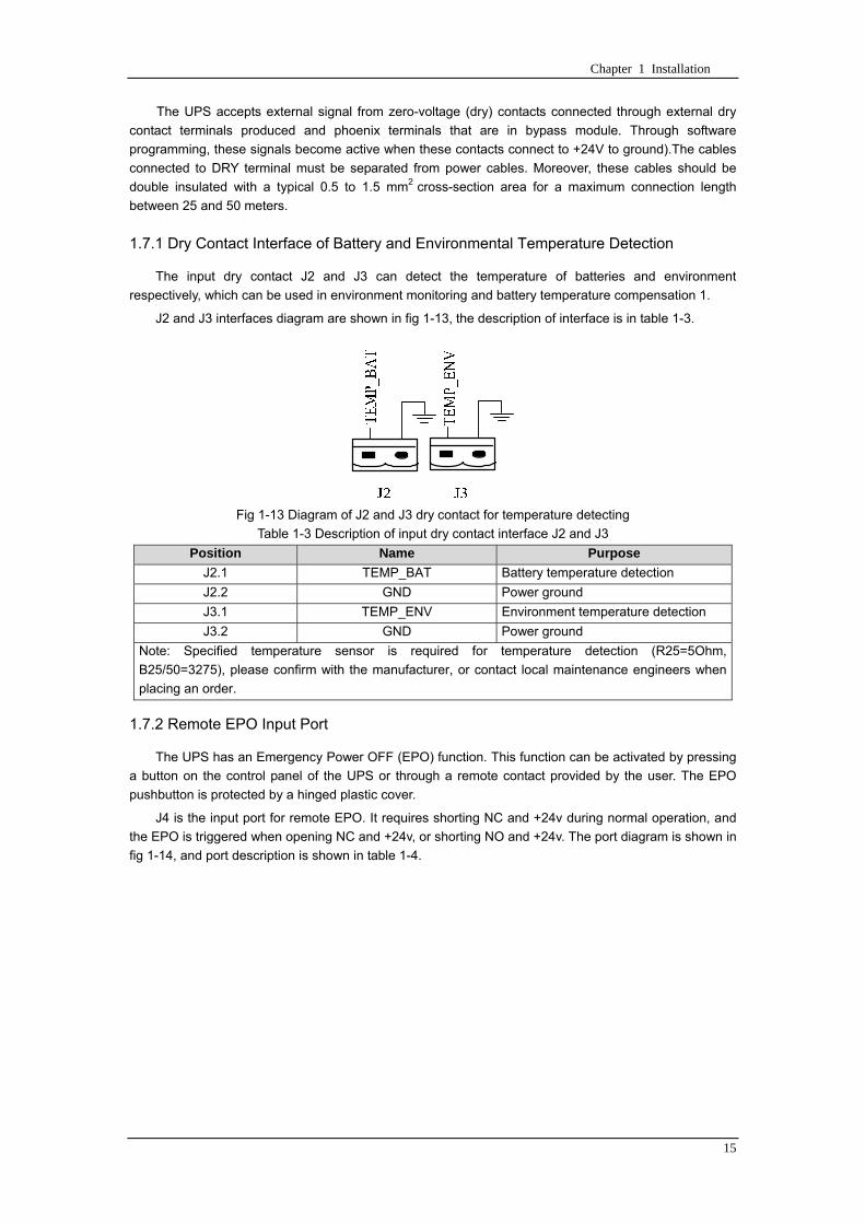
Chapter 1 Installation
15
The UPS accepts external signal from zero-voltage (dry) contacts connected through external dry
contact terminals produced and phoenix terminals that are in bypass module Through software
programming these signals become active when these contacts connect to +24V to ground)The cables
connected to DRY terminal must be separated from power cables Moreover these cables should be
double insulated with a typical 05 to 15 mm2
cross-section area for a maximum connection length
between 25 and 50 meters
171 Dry Contact Interface of Battery and Environmental Temperature Detection
The input dry contact J2 and J3 can detect the temperature of batteries and environment
respectively which can be used in environment monitoring and battery temperature compensation 1
J2 and J3 interfaces diagram are shown in fig 1-13 the description of interface is in table 1-3
Fig 1-13 Diagram of J2 and J3 dry contact for temperature detecting
Table 1-3 Description of input dry contact interface J2 and J3
Position Name Purpose
J21 TEMP_BAT Battery temperature detection
J22 GND Power ground
J31 TEMP_ENV Environment temperature detection
J32 GND Power ground
Note Specified temperature sensor is required for temperature detection (R25=5Ohm
B2550=3275) please confirm with the manufacturer or contact local maintenance engineers when
placing an order
172 Remote EPO Input Port
The UPS has an Emergency Power OFF (EPO) function This function can be activated by pressing
a button on the control panel of the UPS or through a remote contact provided by the user The EPO
pushbutton is protected by a hinged plastic cover
J4 is the input port for remote EPO It requires shorting NC and +24v during normal operation and
the EPO is triggered when opening NC and +24v or shorting NO and +24v The port diagram is shown in
fig 1-14 and port description is shown in table 1-4
Chapter 1 Installation
16
Fig 1-14 Diagram of input port for remote EPO
Table 1-4 Description of input port for remote EPO
Position Name Purpose
J41 EPO_NC EPO is activated when disconnecting fromJ42
J42 +12V +24V connect the common terminal of NC and NO
J43 +12V EPO is activated when shorting with J42
The EPO is triggered when shorting pin 2 and 3 or opening pin 2 and 1 of J4
If an external emergency stop facility is required it is connected via the reserved terminals of J4
The external emergency stop facility needs to use shielded cables to connect to the normally
openclosed remote stop switch between these two pins If this facility is not used then pin 3 and pin 4 of
J4 must be open or pin 1 and pin 2 of J4 must be shorted
Note
1 The emergency stop action within the UPS will shut down the rectifier inverter and static bypass
However it does not internally disconnect the mains input power supply To disconnect ALL power to
the UPS open the upstream input circuit breaker(s) when the EPO is activated
2 Pin 1 and 2 of J4 have been shorted before the UPS is delivered
173 Generator Input Dry Contact
J5 is status interface for generator connection Connect pin 2 of J5 with + 24 power supply it
indicates that the generator has been connected with the system The interface diagram is shown in fig
1-15 and interface description is shown in table 1-5
Chapter 1 Installation
17
Fig 1-15 Diagram of status interface and connection of generator
Table 1-5 Description of maintenance bypass switch and output switch status interface
Position Name Purpose
J51 +24V +24V power supply
J52 GEN Connection status of generator
J53 GND Power ground
174 BCB Input Port
J6 and J7 are the ports of BCB The port diagram is shown in fig 1-16 and description is shown in
table 1-6
BC
B_D
RV
BC
B_C
ON
T
J6 J7
BC
B_O
NL
+24V+24V
+24V
Fig 1-16 BCB Port
Table 1-6 Description of BCB port
Position Name Description
J61 BCB_DRV BCB actuating signal provide the actuating signal of +18V 20mA
J62 BCB_CONT BCB contact status connect with the normally open signal of BCB
J71 GND Power ground
J72 BCB_ONL BCB on-linendashinput (normally open) BCB is on-line when the signal
is connecting with GND
175 Battery Warning Output Dry Contact Interface
J8 is the output dry contact interface which outputs the battery warnings of low or excessive
voltage when the battery voltage is lower than set value an auxiliary dry contact signal will be
provided via the isolation of a relay The interface diagram is shown in fig 1-17 and description is
shown in table 1-7
Generator
Chapter 1 Installation
18
Fig 1-17 Battery warning dry contact interface diagram
Table 1-7 Battery warning dry contact interface description Position Name Purpose
J81 BAT_LOW_NC Battery warning relay (normally closed) will be open during warning
J82 BAT_LOW_NO Battery warning relay (normally open) will be closed during warning
J83 GND Center of battery warning relay
176 Integrated Warning Output Dry Contact Interface
J9 is the integrated warning output dry contact interface when one or more than one preset
warning is triggered the system will send an integrated warning information and provide an auxiliary
dry contact signal via the isolation of a relay The interface diagram is shown in fig 1-18 and description
is shown in table 1-8
Fig 1-18 Integrated warning dry contact interface diagram
Table 1-8 Integrated warning dry contact interface description Position Name Purpose
J91 ALARM_NC Integrated warning relay (normally closed) will be open during warning
J92 ALARM_NO Integrated warning relay (normally open) will be closed during warning
J93 GND Centre of integrated warning relay
177 Mains Failure Warning Output Dry Contact Interface
J10 is the output dry contact interface for mains failure warning when the mains fails the system
will send a mains failure warning information and provide an auxiliary dry contact signal via the isolation
of a relay The interface diagram is shown in fig 1-19 and description is shown in table 1-9
Chapter 1 Installation
19
Fig 1-19 Mains failure warning dry contact interface diagram
Table 1-9 Mains failure warning dry contact interface description Position Name Purpose
J91 UTI_FAIL_NC Mains failure warning relay(normally closed) will be open during
warning
J92 UTI_FAIL_NO Mains failure warning relay normally open) will be closed during
warning
J93 GND Centre of mains failure warning relay
178 RS232 Port and SNMP Card Port
RS232 and RS485 Port provide serial data which can be used for commissioning and maintenance
by authorized engineers or maintainers or can be used for networking or integrated monitoring system in
the service room
SNMP Card Port used for field installation of the communication option card(SNMP card)
179 LBS (Load Bus Synchronizer) Port
The dual bus system (DBS) consists of two independent UPS rack module systems as shown in fig
1-20 The dual bus system is configured for high availability and is suitable for powering the load with
dual inputs If the load is single-input load the static transfer switch and LBS control is recommended to
maintain both UPS outputs synchronized for uninterrupted transfers Please install the system according
to the installation descriptions for different system configurations
The dual bus system is supported by UPS it requires connecting the LBS signal cables of two UPS
when constructing the dual bus system please refer to relevant chapter for detailed configuration and
installation and the system software shall be configured as required
UPS 1
LBS
监控旁路模块 UPS 2
LBS
监控旁路模块
Fig 1-20 LBS Connection Diagram
18 Installation Drawing
Please refer to fig 1-21 fig 1-22 fig 1-23 and fig 1-24
UPS 1 monitoring bypass module
UPS 2 monitoring bypass module
Chapter 1 Installation
20
Fig 1-21 Installation Diagram
Chapter 1 Installation
21
顶视图
2m cabinet front view
16 m cabinet (front view)
Fig 1-22 UPS front view (Unit mm)
Top view
Chapter 1 Installation
22
A
2m cabinet
A
16m cabinet
Fig 1-23 UPS back view
Chapter 1 Installation
23
A
A处放大
Fig 1-24 UPS front view
Amplification of A
24 Chapter 2 Operations
24
Chapter 2 Operations
This chapter introduces the basic knowledge of UPS operations including working principle
operation mode battery management and protection
Warning Hazardous mains voltage andor battery voltage present(s)behind the protective cover
The components that can only be accessed by opening the protective cover with tools cannot be
operated by user
Only qualified service personnel are authorized to remove such covers
21 Introduction
UPS provides the critical load (such as communication and data processing equipment) with high
quality uninterruptible AC power The power from UPS is free from voltage and frequency variations and
disturbances (interruption and spike) experienced at the Mains AC input supply
This is achieved through high frequency double conversion power pulse width modulation (PWM)
associated with full digital signal processing control (DSP) which features high reliability and
convenience for use
211 Principle
As shown in fig 2-1 the AC input mains source is supplied at UPS input and converted into a DC
source This DC source feeds the Inverter that converts the DC source into a clean and input
independent AC source The battery powers the load through the inverter in case of an AC input mains
power failure The utility source can also power the load through the static bypass
When the UPS needs maintenance or repair the load can be transferred to maintenance bypass
without interruption and the power module and bypass module can be removed for maintenance
Chapter 2 Operations 25
25
Fig 2-1 System principle framework
212 Bypass Module
The circuit blocks labeled ldquobypass modulerdquo in fig 2-1 contain electronically controlled switching
circuits that enable the critical load to be connected to either the inverter output or to a bypass power
source via the static bypass line During normal system operation the load is connected to the inverter
but in the event of a UPS overload or inverter failure the load is automatically transferred to the static
bypass line
To provide a clean (no-break) load transfer between the inverter output and static bypass line the
inverter output and bypass supply must be fully synchronized during normal operating conditions This is
achieved through the inverter control electronics which makes the inverter frequency track that of the
static bypass supply provided that the bypass remains within an acceptable frequency window
A manually controlled maintenance bypass supply is incorporated into the UPS design It enables
the critical load to be powered from the utility (bypass) supply while the UPS is shut down for routine
maintenance
Note
When the UPS is operating in bypass mode or on maintenance bypass the connected equipment is
not protected from power failures or surges and sags
22 Operation Mode
The MD UPS is an on-line double-conversion reverse-transfer UPS that permits operation in these
modes
Normal mode
26 Chapter 2 Operations
26
Battery mode
Auto-Restart mode
Bypass mode
Maintenance mode (manual bypass)
ECO mode
Frequency converters mode
221 Normal Mode
The UPS inverter power modules continuously supplies the critical AC load The rectifiercharger
derives power from the AC mains input source and supplies DC power to the inverter while
simultaneously FLOAT or BOOST charging its associated backup battery
222 Battery Mode
Upon failure of the AC mains input power the inverter power modules which obtains power from the
battery supplies the critical AC load There is no interruption in power to the critical load upon failure
After restoration of the AC mains input power the ldquoNormal Moderdquo operation will continue automatically
without the necessity of user intervention
Note UPS can also be started through battery (charged) mode via battery cold start function upon
failure of the AC mains Therefore the battery power can be used independently to improve the
utilization rate of UPS
223 Auto-Restart Mode
The battery may become exhausted following an extended AC mains failure The inverter shuts
down when the battery reaches the End of Discharge voltage (EOD) The UPS may be programmed to
ldquoAuto Recovery after EODrdquo after a delay time if the AC mains recovers This mode and any delay time
are programmed by the commissioning engineer
During the process of delay time the battery will be charged by UPS to prevent any risks to load
equipment from future mains failure
224 Bypass Mode
If the inverter overload capacity is exceeded under normal mode or if the inverter becomes
unavailable for any reason the static transfer switch will perform a transfer of the load from the inverter
to the bypass source with no interruption in power to the critical AC load
225 Maintenance Mode
A manual bypass switch is available to ensure continuity of supply to the critical load when the UPS
becomes unavailable eg during a maintenance procedure
Note This manual bypass switch is fitted in all UPS modules Transfer UPS system to bypass
module for power supply first then close maintenance bypass switch Q2 followed by Q1 and Q3
Warning hazard may occur after transferring to maintenance bypass
After UPS being transferred to maintenance bypass power module and bypass module do not work
no display on LCD and input and output terminals as well as N bus are electrically connected
Chapter 2 Operations 27
27
226 ECO Mode
If economical (ECO) mode is selected the double-conversion UPS will stop to work so as to save
energy During the operation of ECO mode the load power will be supplied by bypass preferentially
When bypass power is within the range of normal frequency and voltage load power will be supplied by
bypass or the system will transfer to inverter input followed by load power interruption which extends
within 34 of the utility period Eg when the frequency is 50Hz the interruption time will be less than
15ms when the frequency is 60Hz the time will be less than 125ms
227 Frequency Converters Mode
If the frequency converter configuration is used by UPS it will provide 50Hz or 60Hz stable output
frequency The range of output frequency is 40Hz~70Hz Under this mode static bypass is unavailable
but battery can be selected according to the actual requirements of battery mode
23 Battery Management
231 Normal Function
The following functions should be fitted by commissioning engineers with specified software
1 Constant current boost charging
Current can be set up
2 Constant voltage boost charging
Voltage of boost charging can be set as required by the type of battery
For Valve Regulated Lead Acid (VRLA) batteries maximum boost charge voltage should not
exceed 24V cell
3 Float charge
Voltage of float charging can be set as required by the type of battery
For VRLA float charge voltage should be between 22V to 23V
4 Float charge temperature compensation (optional)
A coefficient of temperature compensation can be set as required by the type of battery
5 End of discharge (EOD) protection
If the battery voltage is lower than the EOD the battery converter will shut down and the battery is
isolated to avoid further battery discharge EOD is adjustable from 16V to 175V per cell (VRLA) or 09
to 11 V per cell
6 Battery low warning time
It is adjustable between 3 and 60 minutes The default is 5 minutes
232 Advanced Functions (Battery Self-checking and Maintenance)
At periodic intervals 20 of the rated capacity of the battery will be discharged automatically and
the actual load must exceed 20 of the rated UPS (KVA) capacity If the load is less than 20
auto-discharge cannot be executed The periodic interval can be set from 30 to 360 days The battery
self-test can be disabled
ConditionsmdashBattery at float charge for at least 5 hours load equal to 20~100 of rated UPS capacity
TriggermdashManually through the command of ldquoBattery Maintenance Testrdquo in LCD panel or automatically
Battery Self-Test Intervalmdash30-360 days (default setting is battery self-test disabled)
28 Chapter 2 Operations
28
24 Battery Protection
The following functions should be fitted by commissioning engineers with specified software
1 Battery Low Pre-warning
The battery under voltage pre-warning occurs before the end of discharge After this pre-warning
the battery should have the capacity for 3 remaining minutes discharging with full load The time is user
configured from 3 to 60 minutes
2 Battery discharge (EOD)off protection
If the battery voltage is lower than the EOD the battery converter will be shut down EOD is
adjustable from 16V to 175V per cell (VRLA) or 09 to 11 V per cell (NiCd)
3 Battery Circuit Breaker (BCB) Alarm
The alarm occurs when the battery disconnect device disconnects The external battery connects to
the UPS through the external battery circuit breaker The circuit breaker is manually closed and tripped
by the UPS control circuit
Chapter 3 Operation Instructions 29
29
Chapter 3 Operating Steps
This chapter describes UPS operation instructions in detail
All functional keys and LED display involved in operation instructions please refer to chapter 4
During operation the buzzer alarm may occur at any time Select ldquomuterdquo on LED to muffle the audible
alarm
Warning-Hazardous mains voltage andor battery voltage present(s)behind the protective cover
1 The components that can only be accessed by opening the protective cover with tools cannot be
operated by user
2 Only qualified service personnel are authorized to remove such covers
31 Power Switches
As shown in fig 3-1 open the front door of UPS the power switch is visible which includes input
switch output switch and maintenance bypass switch (with anti-misoperation stop plate)
输入开关 输出开关
维修旁路开关
Fig 3-1 Power switch location diagram
32 UPS Start-up
The UPS system only has a maintenance bypass isolating switch and all the other transfers are
processed automatically by internal control logics
Input switch Output switch
Maintenance bypass switch
30 Chapter 3 Operating Instructions
30
321 Normal Module Start
This procedure must be followed when turning on the UPS from a fully powered down condition
The operating procedures are as follows
Warning
This procedure results in mains voltage being applied to the UPS output terminals If any load
equipment is connected to the UPS output terminals please check with the load user that it is safe to
apply power If the load is not ready to receive power then ensure that it is safely to close the output
switch of external distribution cabinet
1 Close UPS output switch and input switch in turns
The LCD starts up at this time The Rectifier indicator flashes during the startup of rectifier The
rectifier enters normal operation state and after about 30s the rectifier indicator goes steady green After
initialization the bypass static switch closes The UPS Mimic LEDs will indicate as shown in table 3-1
Table 3-1 Indicator status
LED Status
Rectifier indicator Green
Battery indicator Red
Bypass indicator Green
Inverter indicator Off
Load indicator Green
Status indicator Green
Note
The output circuit breaker must be closed first followed by input circuit breaker or the rectifier cannot
be started and alarm ldquorectifier failurerdquo
The inverter starts up at this time the inverter indicator flashes After the rectifier enters normal
operation state UPS power supply will transfer from bypass to inverter then the bypass indicator turns
off and load indicator lights The status of indicators is shown in table 3-2
Table 3-2 Indicator Status
LED Status
Rectifier indicator Green
Battery indicator Red
Bypass indicator Off
Inverter indicator Green
Load indicator Green
Status indicator Green
Close external battery switch again battery indicator turns off a few minutes later the battery will be
charged by UPS which will enter normal mode operation The indicator status is shown in table 3-3
Table 3-3 Indicator status
LED Status
Rectifier indicator Green
Battery indicator Green
Bypass indicator Off
Inverter indicator Green
Load indicator Green
Status indicator Green
322 Operating steps of Battery cold Start
1 Check if the batteries have been connected close the external battery switch
Chapter 3 Operation Instructions 31
31
2 Press the red start-up button of battery under the rectifier input circuit breaker for 3 seconds (see fig
3-2)
The LCD starts up at this time The green battery indicator flashes The rectifier enters normal
operation states and after about 30s the battery indicator goes steady green
3 The inverter starts up automatically the green inverter indicator flashes The output of inverter
appears after 60s The UPS works on battery mode
32 Chapter 3 Operating Instructions
32
电池启动按钮
Fig 3-2 Position diagram of battery startup button
Battery startup button
Chapter 3 Operation Instructions 33
33
33 Procedure for Switching between Operation Modes
331 Procedure for Switching the UPS into Battery mode from Normal Mode
Open input switch to cut off the mains UPS enters the battery mode If UPS should be switched to
normal mode wait for a few seconds before close input switch so as to supply the mains again 10s
later the rectifier will start up automatically to supply power to the inverter
332 Procedure for Switching the UPS into Bypass mode from Normal Mode
Select ldquoTran Byprdquo on the LCD or press ldquooffrdquo buttons of each power module in turn
Note
In bypass mode the load is directly fed by the mains power instead of the pure AC power from the
inverter
333 Procedure for Switching the UPS into Normal from Bypass Mode
Select exit bypass mode on the LCD
334 Procedure for Switching the UPS into a Maintenance Bypass from Normal Mode
In normal operation this operation instruction will switch the load from inverter input to maintenance
bypass
Caution
Before making this operation read messages on display to be sure that bypass supply is regular and
the inverter is synchronous with it so as not to have a risk of a short interruption in powering the load
1 Press ldquoTran Byprdquo on the LCD or press ldquooffrdquo on each power module in turns
If press rdquoTran Byprdquo on the LCD the inverter indicator will flash green and the buzzer will alarm
If press ldquooffrdquo on each power module in turns the inverter indicator will go off and the buzzer will
alarm
The load will be transferred to static bypass and the inverter is closed
2 Close maintenance bypass switch Q2 the load power will be supplied by maintenance bypass and
then open the inverter circuit breaker Q1 output switch Q3 and battery switch
Warning
If you need to maintain the module wait for 10 minutes to let the DC bus capacitor fully discharge
before removing corresponding module
335 Procedure for Switching the UPS into Normal from a Maintenance Bypass Mode
This procedure can transfer the load to normal main mode when the UPS is operating under the
maintenance bypass mode
1 Close output switch Q3 and main switch Q1
The bypass indicator goes green and the load power will be supplied by bypass and maintenance
bypass
2 Open maintenance bypass switch Q2
34 Chapter 3 Operating Instructions
34
The load power is supplied by bypass In the meantime the rectifier starts up rectifier indicator goes
green 30s later at this time the inverter will start up automatically and transfer to inverter mode 1 min
later automatically
3 Close external battery switch the battery indicator goes off Check if the battery voltage on LCD
display is normal
34 Procedure for Completely Powering down a UPS
If you need to power down the UPS completely follow the procedures in section 334 to transfer the
UPS from normal mode to maintenance bypass mode
If you need to isolate the UPS from the AC power supply you should open the external input switch
35 EPO Procedure
The EPO button on UPS operator control and display panel is designed to switch off the UPS in
emergency conditions (eg fire flood etc)To achieve this just press the EPO button and the system
will turn off the rectifier inverter and stop powering the load immediately (including the inverter and
bypass output) and the battery stops charging or discharging
If the input utility is present the UPS control circuit will remain active however the output will be
turned off To completely isolate the UPS you need to open the external mains input supply to the UPS
rack
36 Language Selection
The LCD is available in two languages Chinese English and Korean
The language can be selected through LCD prompt window
37 Control Password
When the LCD displays ldquoinput control password 1rdquo the initial password is 12345678
Chapter 4 Operator Control and Display Panel 35
35
Chapter 4 Operator Control and Display Panel
This chapter introduces the functions and operation instructions of the parts on UPS operator control
and display panel in detail and provides LCD display information including LCD display types detailed
menu information prompt window information and UPS alarm list
41 Introduction
The operator control and display panel is located on the front panel of the UPS Through this LCD
panel the operator can operate and control the UPS and check all measured parameters UPS and
battery status and event and alarm logs The operator control panel is divided into three functional areas
as shown in fig 4-1 mimic current path LCD display amp Menu keys and Control and Operation Keys The
detailed description of parts on operator control and display panel is shown in table 4-1
Fig 4-1 UPS operator control and display panel
Table 4-1 Description of UPS operator control and display panel
Part No Function Button Function
REC Rectifier indicator EPO EPO switch
BAT Battery indicator TAB switch
BYP Bypass indicator ENTER confirm
INV Inverter indicator ESC exit
OUTPUT Load indicator
STATUS Status indicator
36 Chapter 4 Operator Control and Display Panel
36
411 LED Indicator
The LEDs shown on the mini current path represent the various UPS power paths and show the
current UPS operating status The status description of indicators is shown in table 4-2
Table 4-2 Status description of indicator
Indicator State Purpose
Rectifier
indicator
Steady green Rectifier normal for all modules
Flashing green Rectifier for at least on module normal mains normal
Steady red Rectifier fault
Flashing red Mains abnormal for at least one module
Off Rectifier not operating
Battery
indicator
Steady green Battery charging
Flashing green Battery discharging
Steady red
Battery abnormal (battery failure no battery or battery reverse) or
battery converter abnormal (failure over current or over temperature)
EOD
Flashing red Battery low voltage
Off Battery and battery converter normal battery not charging
Bypass
indicator
Steady green Load power supplied by bypass
Steady red Bypass power abnormal or out of normal range or static bypass
switch fault
Flashing red Bypass voltage abnormal
Off Bypass normal
Inverter
indicator
Steady green Load power supplied by inverter
Flashing green Inverter On start synchronization of standby (ECO mode) for at least
one module
Steady red System power not supplied by inverter inverter fault for at least one
module
Flashing red System power supplied by inverter inverter fault for at least one
module
Off Inverter not operating for all modules
Load
indicator
Steady green UPS output ON and normal
Steady red UPS output overload and overtime or output short or output no power
supply
Flashing red Overload output of UPS
Off No output of UPS
Status
indicator
Steady green Normal operation
Steady red Failure
412 Audible Alarm (buzzer)
There are two different types of audible alarm during UPS operation as shown in table 4-3
Table 4-3 description of audible alarm
Alarm Purpose
Two short alarm with
a long one
when system has general alarm (for example AC fault) this audible alarm
can be heard
Continuous alarm When system has serious faults (for example fuse or hardware fault) this
audible alarm can be heard
Chapter 4 Operator Control and Display Panel 37
37
413 Functional Keys
There are 4 functional keys on operator control and display panel which are used together with LCD
The functions description is shown in table 4-4
Table 4-4 Functions of functional keys
Functional key Functions
EPO switch To cut off the load power to shut down the rectifier inverter static
bypass and battery
TAB switch
ENTER confirm
ESC exit
42 LCD Display Type
Following the self-check of UPS LCD display the main LCD display is shown as fig 4-2 which can
be divided into three display windows system information data command and current record
Fig 4-2 Main LCD display
The description of LCD icon is shown in table 4-5
Table 4-5 Description of LCD icons
Icon Description
Bypass parameter
UPS system
information
window
Data
command
window
Current
record
window
38 Chapter 4 Operator Control and Display Panel
38
Icon Description
Main input parameter
History file system information
Function setting (display calibration password setting time setting date format
communication protocol and language setting) system setting (used by product
maintainers)
Battery data battery parameter setting (used by service staff)
Test (battery self-test battery maintenance)
Functional keys used by service staff (fault clearing history file clearing noise
clearing manual switch of bypass) userrsquos setting (system mode machine
number system ID output voltage adjustment frequency tracing speed
frequency tracing limit)
Output parameter
Load
Noise clearing noise clearing cancel
Log view page updown
Select a icon on LCD as shown in fig 4-3 to view the UPS parameter represented by this icon eg
select the LCD will display the data of system main input
Chapter 4 Operator Control and Display Panel 39
39
Fig 4-3 Select data
Or select and confirm a module as shown in fig 4-4 the LCD will display the
operating status of this module
Fig 4-4 Select a module
40 Chapter 4 Operator Control and Display Panel
40
Select in the operating status of a module to view the main input data of this module
Select in the operating status of a module to view the main output data of this module
Select in the operating status of a module to view the load data of this module
Select in the operating status of a module to view the maintenance code and module
software code of this module
Select to return to the previous page
Select to return to the home page
Default display
During the operation of system if therersquos no alarm in 2 min the system will display default After a
short delay the backlight of LCD display goes off press any key to reactivate the display
43 Detailed Description of Menu Items
The LCD main display shown in fig 4-2 is described in details below
UPS information window
UPS information window display the current time and UPS name The information of the window is
not necessary for the user to operate The information of this window is given in table 4-6
Table 4-6 Description of items in UPS system information window
Display contents Meaning
MD12020 UPS Name
1200 Current Time (format 24 hours hours minute)
UPS menu and data window
UPS menu window displays the menu name of data window while the data window displays the
related contents of selected menu in menu window Select UPS menu and data window to browse
related parameters of UPS and set related functions The details are given in table 4-7
Table 4-7 Item description of UPS menu and data window
Menu name Menu item Meaning
Main input
V phase(V) V phase
I phase(A) I phase
Freq(Hz) Input frequency
PF Power factor
Bypass input
V phase(V) V phase
Freq (Hz) Bypass frequency
I phase(A) I phase
PF Power factor
AC output
V phase(V) V phase
I phase(A) I phase
Freq (Hz) Output frequency
PF Power factor
This UPS Sout (kVA) Sout Apparent Power
Chapter 4 Operator Control and Display Panel 41
41
Menu name Menu item Meaning
modulersquos
load
Pout (kW) Pout Active Power
Qout (kVAR) Qout Reactive Power
Load () Load (The percentage of the UPS rating load)
Battery data
Environmental
Temp Environmental Temp
Battery
voltage(V) Battery bus voltage
Battery current
A) Battery bus current
Battery
Temp() Battery Temp
Remaining Time
(Min) Remaining battery backup time
Battery capacity
() The percentage compared with new battery capacity
battery
equalized
charging
Battery is equalized charging
battery float
charging Battery is float charging
Battery
disconnected Battery is not connected
Current
record (current alarm)
Display all current alarm The alarm list displayed on LCD of
UPS operator control and display panel please refer to table 4-9
History
record (history alarm)
Display all history alarm The alarm list displayed on LCD of
UPS operator control and display panel please refer to table 4-9
Menu
Language
(language
option) 2 languages can be selected
Settings
Display
calibration Adjust the accuracy of LCD display
Date format set MM DD YYYY and YYYY MM DD formats can be selected
Date amp Time DateTime set
Language set User can set the language (Chinese and English)
Communication
mode
Set communication mode MODBUS Power protocol and
company custom protocol modes can be selected Power
protocol mode can be divided into equipment address baud
rate set MODBUS protocol mode can be divided into
communication mode (RTUASCⅡ) equipment address
baud rate and check-bit set Company custom protocol mode
is the customed protocol of the company no option is
available
Control
password set User can modify control password 1
Test
Command
(Battery Test
Control
Battery
maintenance
test
This test will lead to the battery being partly discharged to
activate battery at the same time the approximate battery
capacity will be obtained Bypass must be in normal condition
the battery capacity should be above 25
42 Chapter 4 Operator Control and Display Panel
42
Menu name Menu item Meaning
Battery
self-check test
UPS switches to battery discharge for discharging to test if the
battery is normal Bypass must be in normal condition the
battery capacity should be above 25
Stop testing Manually Stop the test including maintenance test capacity test
UPS system
information
Monitoring
software version Provide monitoring software version
Rectified
software version Provide rectified software version
Inverted
software version Provide inverted software version
Serial No The serial no set when delivery from the factory
Rated
information Network setting of system operating
Module type Type of the module
44 Alarm List
The follow table 4-8 gives the complete list of all the UPS events displayed by history record window
and current record window
Table 4-8 Alarm List
Alarm Explanation
UPS power supply The system is in normal inverted power supply status
Bypass power
supply The system is in bypass power supply status
No power supply System no output
Battery equalized
charging Battery is in boost charging
Battery float
charging Battery is in float charging
Battery discharging The system is operating in battery discharging status
Battery connected Battery is connected
Battery
disconnected Battery is not connected
Maintenance circuit
breaker close Maintenance circuit breaker is close
Maintenance circuit
breaker open Maintenance circuit breaker is open
Emergency
shutdown System emergency shutdownEPO
Generator
connected External generator is connected
Mains abnormal Input mains abnormal
Bypass phase
conversion Bypass input phase converse
Bypass voltage
abnormal Bypass input voltage abnormal
Bypass fault Bypass fault
Bypass overload Bypass output is overload
Up to bypass
overtime of Bypass is overtime of overload
Chapter 4 Operator Control and Display Panel 43
43
Alarm Explanation
overload
Bypass frequency
tracing exceeds Bypass frequency is out of the tracing range
Switch times up to
in this hour
The times of switch between bypass and inverter exceeds 5 times in the latest
hour
Output short System output short
Battery EOD Battery voltage achieves shutdown point
Battery self-check The system enters battery self-check mode
Battery self-check
success Battery normal during system self-check
Battery manual
check failure Battery fault during system self-check
Battery
maintenance The system is in battery maintenance status
Battery
maintenance
success
Battery maintenance status completes
Battery
maintenance failure Battery maintenance process is not normal
Stop testing Battery self-check or battery maintenance status stops
Fault clearing Clear the alarmed fault
Delete history
record Delete all history record
N communication
node connected N module is connected to UPS system
N communication
node disconnected N module is not connected to UPS system
N rectifier fault N module rectifier fault
N inverter fault N module inverter fault
N rectifier
overheat N module rectifier overheat
N fan fault N module fan fault
N output overload N module output overload
N overtime of
overload N module output overtime of overload
N inverter
overheat N module inverter overheat
Inverter power
supply ban Inverter power ban supply
Manual switch of
bypass Switch the system to bypass output manually
Cancel manual
switch of bypass Switch the system from bypass to inverter output manually
Battery low voltage Battery low voltage
Battery reversal Battery polarity reversal
N inverter
protection N module inverter protection
Input N line
disconnected System input N line is not connected
Bypass fan fault Bypass module fan fault
N manual N module manual power off
44 Chapter 4 Operator Control and Display Panel
44
Alarm Explanation
shutdown
Chapter 5 Maintenance 45
45
Chapter 5 Installation of Parallel Operation System
The parallel operation system is installed as required by the installation procedures of the single
system and this chapter
The single devices are put parallel and connected as shown in fig 5-1 and the difference between
the lengths of the output cables of the single devices is not more than 10m It is recommended to use an
external bypass cabinet to facilitate maintenance and system testing
Fig 5-1 Typical 1+N parallel operation system
Note when the load exceeds is the capacity of the single device the maintenance bypass
switch CB3 must be removed
The cables for the parallel operation provide double insulation shielding up to 30m long the control
cables for the parallel operation must be connected with all single devices to form a closed loop as
shown in fig5-2
Other power supplies
Rectifier
Charger Inverter Inverter
Output power supply
Load connected
Mains power input L1 L2 L3 N terminal
Mains power inputL1 L2 L3 N terminal
Rectifier
Charger
46 Chapter 5 Maintenance
46
Fig5-2 parallel cables
Chapter 5 Maintenance 47
47
Chapter 6 Maintenance
This chapter introduces UPS maintenance including the maintenance instructions of power module
monitoring bypass module and the change method of dust filter
61 Instruction to Power Bypass and Output Power Distribution
Module
611 Precautions
1 Only maintaining engineers can maintain the power module and monitoring bypass module
2 In principle the power module and bypass module should be disassembled from top to bottom so
as to prevent any inclination from high gravity centre of the cabinet
3 To ensure the safety before maintaining power module and bypass module be sure to use a
multimeter to measure the DC bus capacitor voltage and ensure the voltage is below 60V before
operation and use a multimeter to measure the voltage between operating parts and the earth to
ensure the voltage is lower than hazardous voltage ie DC voltage is lower than 60Vdc and AC
maximum Voltage is lower than 424Vac
4 Bypass module doesnrsquot support any hot insertion and extraction only when UPS is in maintenance
bypass mode or UPS is completely power off can the bypass module be disassembled
5 The module can be maintained 10 mins after extracting power module and bypass module which
can be inserted into the cabinet 10 mins later
612 Instruction to Power Module
Suppose UPS were in normal mode and bypass were normal a module shall be maintained at
first
1 Press OFF of the module with a pin point or other tiny matter the module will shut down
automatically and exit the system
Note ensure if the remaining module will be overload when exiting a module If therersquos any risk of
overload transfer the whole UPS system to bypass followed by other operations
2 Take off the fixing bolt on the two sides of front and back plate of power module 10 mins later
extract the module from the cabinet
3 After maintaining the module push the module into the equipment cabinet (the interval between
two modules shall be more than 10s) fix the screw on the two sides Then the module will be
connected to UPS system automatically
613 Instruction to Bypass Module
Suppose UPS were in normal mode and the bypass were normal
1 Select LCD touch screen manual switch of bypass the UPS power will be supplied by bypass
2 Close maintenance bypass switch the UPS power will be supplied by maintenance bypass
3 Open UPS output switch and input switch
4 Open external battery switch
48 Chapter 5 Maintenance
48
5 Take off the fixing bolt at the two sides of front board of bypass module extract the front cable
assembly of the module and extract the module from the cabinet
6 After maintaining the module insert the module into the cabinet tighten the screw at the two sides
and connect the front cable assembly of manufacturerrsquos module
7 Close UPS output switch and input switch in turn
2 mins later bypass indicator on the operator control and display panel lights on which indicates
the normal power supply of bypass
8 Open maintenance bypass switch the inverter starts automatically 60s later the UPS will transfer
to normal mode
62 Replacing Dust Screen (optional)
As shown in fig 5-1 there are 3~4 dust filters on the back of UPSrsquo front door each screen is held in
place by a bracket on either side of each filter The procedure of replacing each filter is as follows
1 Open the UPSrsquo front door and locate the filters on the back side of the front door
2 Remove one bracket
3 Remove the dust screen to be replaced and insert the clean one
4 Reinstall the bracket
防尘网固定条
Fig 5-1 Dust screen on the back side of UPS front door
Bracket
Dust screen
Appendix 2 Toxic or Hazardous Materials or Elements Identification Table 49
49
Chapter 7 Product Specification
This chapter provides UPS product specification
71 Applicable Standards
The UPS has been designed to conform to the following European and international standards
Table 6-1 Compliance with European and International Standards
Item Normative reference
General safety requirements for UPS
used in operator access areas EN50091-1-1IEC62040-1-1AS 62040-1-1
Electromagnetic compatibility (EMC)
requirements for UPS EN50091-2IEC62040-2AS 62040-2(C3)
Method of specifying the performance
and test requirements of UPS EN50091-3IEC62040-3AS 62040-3(VFI SS 111)
Note The above mentioned product standards incorporate relevant compliance clauses with generic
IEC and EN standards for safety (IECENAS60950) electromagnetic emission and immunity
(IECEN AS61000 series) and construction (IECENAS60146 series and 60950)
72 Environmental Characteristics
Table 6-2 Environmental Properties
Items Unit Requirements
Acoustic noise level at 1
meter dB 550
Altitude of Operation m le1000m above sea level derate power by 1 per 100m
between 1000m and 2000m
Relative Humidity RH 0 to 95 non condensing
Operating Temperature 0 to 40 deg Battery life is halved for every 10degC increase
above 20degC
UPS Storage-Transport
Temperature -20~70
Recommended Battery
Storage Temperature -20~30 (20degC for optimum battery storage)
73 Mechanical Characteristics
Table 6-3 Mechanical Properties
Cabinet Specification Unit MD6010 MD9015
MD12020
MD10010 MD15015
MD20020
Mechanical Dimension
WtimesDtimesH mm 600times900times1600 600times900times2000
Weight kg 151 182
Color NA Black
Protection Level
IEC(60529) NA IP20
50 Chapter 5 Maintenance
50
Module type Unit MU10 MU15 MU20
Mechanical Dimension
WtimesDtimesH mm 440times590times134
Weight kg 21 22 22
Color NA Black
74 Electrical Characteristics (Input Rectifier)
Table 6-4 Rectifier AC input (mains)
Items Unit Parameter
Rated AC Input
Voltage Vac
380400415(three-phase and sharing neutral with the
bypass input)
Input voltage range Vac -40~+25
Frequency2 Hz 5060(range 40Hz~70Hz)
Power factor kWkVA full load 099
THD THDI 3
75 Electrical Characteristics (Intermediate DC Link)
Table 6-5 Battery
Items Unit Parameters
Battery bus
voltage Vdc Nominal plusmn240V one-side range 198V~288V
Quantity of
lead-acid cells Nominal 40=[1 battery(12V) ] 240=[1 battery(2V) ]
Float charge
voltage Vcell(VRLA)
225Vcell(selectable from 22Vcell~235Vcell)
Constant current and constant voltage charge mode
Temperature
compensation mVcl -30(selectable from 0~-50 25 or 30 or inhibit)
Ripple voltage V float le1
Ripple current C10 le5
equalized
charge voltage VRLA
24Vcell(selectable from 230Vcell~245Vcell)
Constant current and constant voltage charge mode
final
discharging
voltage
Vcell(VRLA)
165Vcell(selectable from 160Vcell ~ 1750Vcell) 06C
discharge current
175Vcell (selectable from 165Vcell ~ 18Vcell) 015C
discharge current
(EOD voltage changes linearly within the set range according to
discharge current)
Battery Charge Vcell 24Vcell(selectable from 23Vcell~245Vcell)
Constant current and constant voltage charge mode
Battery
Charging Power
Max Current
kW 10 UPS capacity (selectable from 0~20 UPS capacity)
Appendix 2 Toxic or Hazardous Materials or Elements Identification Table 51
51
76 Electrical Characteristics (Inverter Output)
Table 6-6 Inverter Output (to important load)
Rated
capacity(kVA) Unit 10~200
Rated AC voltage1 Vac 380400415(three-phase four-wire and sharing neutral with the
bypass)
Freqency2 Hz 5060
overload
110 load 1 hour
125 load 10min
150 load 1min
>150 load 200ms
Fault current 340 short current limitation for 200ms
Non linear load
capability 3 100
Neutral current
capability 170
Steady state
voltage stability
plusmn1(balanced load)
plusmn15(100 imbalance load)
Transient voltage
response 4 plusmn5
THD <15(linear load) <5(non linear load3)
Synchronization -
Window Rated frequency plusmn2Hz(selectable plusmn1~plusmn5Hz)
Max change rate of
synch frequency Hzs 1 selectable 01~5
Inverter voltage
range V(ac) plusmn5
Note
1 Factory setting is 380V Commissioning engineers can set to 400V or 415V
2 Factory setting is 50Hz Commissioning engineers can set to 60Hz
3 EN50091-3(1458) peak value factor is 3 1
4 IEC62040-3EN50091-3 including 0~100~0 load transient the recovery time is half
circle to within 5 of stable output voltage
52 Chapter 5 Maintenance
52
77 Electrical Characteristics(Bypass Mains Input)
Table 6-7 Bypass Mains Input
Rated
capacity(kVA) Unit 60 90 100 120 150 200
Rated AC
Voltage1 Vac
380400415
three-phase four-wire sharing neutral with the rectifier input and providing neutral
reference for the output
Rated current A
91380V
87400V
83415V
136380V
130400V
124415V
151380V
144400V
138415V
182380V
174400V
166415V
227380V
216400V
207415V
302380V
288400V
276415V
Overload
125 load long term
130 load 1 hour
150 load 6min
1000 load 100ms
Superior
protection
bypass line
NA Thermal-magnetic breaker the capacity is 125 of rated current output
IEC60947-2 curve C
Current rating
of neutral cable A 17timesIn
Frequency2 Hz 5060
Switch time
(between
bypass and
inverter)
ms Synchronized switch le1ms
Bypass voltage
tolerance Vac
Upper limit +10+15or+20 default +20
Lower limit -10 -20 -30 or-40 default-20
(acceptable stable bypass voltage delay 10s)
Bypass
frequency
tolerance
plusmn25 plusmn5 plusmn10 or plusmn20 default plusmn10
Synchronizatio
n-Window Hz Rated frequencyplusmn2Hz (selectable from plusmn05Hz~plusmn5Hz)
Note
1 Factory setting is 400V Commissioning engineers can set to 380V or 415V
2 Factory setting is 50Hz Commissioning engineers can set to 60Hz For example UPS is set to frequency
inverter mode and then bypass status will be neglected
78 Efficiency
Table 6-8 Efficiency Loss and Air Exchange
Rated Efficiency (kVA) Unit 10~200kVA
Normal mode(dual conversion) 95
ECO mode 99
Battery discharging efficiency (DCAC) (battery at nominal voltage 480Vdc and full-rated linear load)
battery mode 95
Appendix 2 Toxic or Hazardous Materials or Elements Identification Table 53
53
Appendix A A Guidebook to Ordering and Selection of MU System
MD series UPS module can be divided into equipment cabinet and power module For the cabinet
lectotype please refer to the description in fig 6-1
Fig 6-1 Cabinet Selection
For single power module type please refers to the description in fig 6-2
Fig 6-2 Power Module Selection
Egg the requirements of a plant room are given below
The maximum power supply of the plant room is 120kVA however it is expected to be expanded to
200kVA in 3-5 years Therefore a 200kVA cabinet and 6 20kVA power module can be purchased to
constitute an uninterrupted 120kVA power system which can be expanded to 200kVA on-line The order
symbol is
1 set MD20020
6 set MU20
Option list
MD-SNMP card remote network monitoring card
MD-1600 dust filter dust screen for 16m cabinet
MD-2000 dust filter dust screen for 2m cabinet
Represents the capacity of a single power module
10 represents 10kVA
15 represents 15kVA
20 represents 20kVA
represents a single power module
Represents UPS system capacitypower module
06010 represents 60kVA10kVA
09015 represents 90kVA15kVA
12020 represents 120kVA20kVA
15015 represents 150kVA15kVA
20020 represents 200kVA20kVA
MD represents UPS cabinet
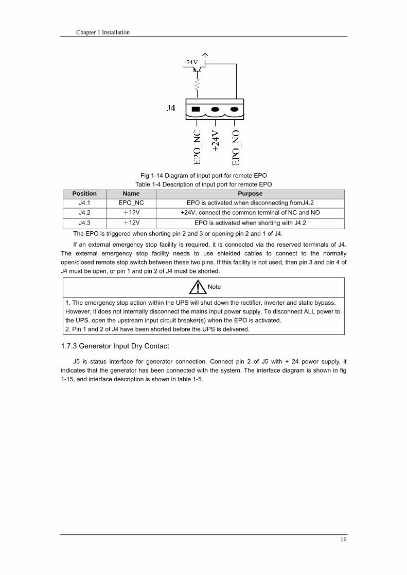
Chapter 1 Installation
16
Fig 1-14 Diagram of input port for remote EPO
Table 1-4 Description of input port for remote EPO
Position Name Purpose
J41 EPO_NC EPO is activated when disconnecting fromJ42
J42 +12V +24V connect the common terminal of NC and NO
J43 +12V EPO is activated when shorting with J42
The EPO is triggered when shorting pin 2 and 3 or opening pin 2 and 1 of J4
If an external emergency stop facility is required it is connected via the reserved terminals of J4
The external emergency stop facility needs to use shielded cables to connect to the normally
openclosed remote stop switch between these two pins If this facility is not used then pin 3 and pin 4 of
J4 must be open or pin 1 and pin 2 of J4 must be shorted
Note
1 The emergency stop action within the UPS will shut down the rectifier inverter and static bypass
However it does not internally disconnect the mains input power supply To disconnect ALL power to
the UPS open the upstream input circuit breaker(s) when the EPO is activated
2 Pin 1 and 2 of J4 have been shorted before the UPS is delivered
173 Generator Input Dry Contact
J5 is status interface for generator connection Connect pin 2 of J5 with + 24 power supply it
indicates that the generator has been connected with the system The interface diagram is shown in fig
1-15 and interface description is shown in table 1-5
Chapter 1 Installation
17
Fig 1-15 Diagram of status interface and connection of generator
Table 1-5 Description of maintenance bypass switch and output switch status interface
Position Name Purpose
J51 +24V +24V power supply
J52 GEN Connection status of generator
J53 GND Power ground
174 BCB Input Port
J6 and J7 are the ports of BCB The port diagram is shown in fig 1-16 and description is shown in
table 1-6
BC
B_D
RV
BC
B_C
ON
T
J6 J7
BC
B_O
NL
+24V+24V
+24V
Fig 1-16 BCB Port
Table 1-6 Description of BCB port
Position Name Description
J61 BCB_DRV BCB actuating signal provide the actuating signal of +18V 20mA
J62 BCB_CONT BCB contact status connect with the normally open signal of BCB
J71 GND Power ground
J72 BCB_ONL BCB on-linendashinput (normally open) BCB is on-line when the signal
is connecting with GND
175 Battery Warning Output Dry Contact Interface
J8 is the output dry contact interface which outputs the battery warnings of low or excessive
voltage when the battery voltage is lower than set value an auxiliary dry contact signal will be
provided via the isolation of a relay The interface diagram is shown in fig 1-17 and description is
shown in table 1-7
Generator
Chapter 1 Installation
18
Fig 1-17 Battery warning dry contact interface diagram
Table 1-7 Battery warning dry contact interface description Position Name Purpose
J81 BAT_LOW_NC Battery warning relay (normally closed) will be open during warning
J82 BAT_LOW_NO Battery warning relay (normally open) will be closed during warning
J83 GND Center of battery warning relay
176 Integrated Warning Output Dry Contact Interface
J9 is the integrated warning output dry contact interface when one or more than one preset
warning is triggered the system will send an integrated warning information and provide an auxiliary
dry contact signal via the isolation of a relay The interface diagram is shown in fig 1-18 and description
is shown in table 1-8
Fig 1-18 Integrated warning dry contact interface diagram
Table 1-8 Integrated warning dry contact interface description Position Name Purpose
J91 ALARM_NC Integrated warning relay (normally closed) will be open during warning
J92 ALARM_NO Integrated warning relay (normally open) will be closed during warning
J93 GND Centre of integrated warning relay
177 Mains Failure Warning Output Dry Contact Interface
J10 is the output dry contact interface for mains failure warning when the mains fails the system
will send a mains failure warning information and provide an auxiliary dry contact signal via the isolation
of a relay The interface diagram is shown in fig 1-19 and description is shown in table 1-9
Chapter 1 Installation
19
Fig 1-19 Mains failure warning dry contact interface diagram
Table 1-9 Mains failure warning dry contact interface description Position Name Purpose
J91 UTI_FAIL_NC Mains failure warning relay(normally closed) will be open during
warning
J92 UTI_FAIL_NO Mains failure warning relay normally open) will be closed during
warning
J93 GND Centre of mains failure warning relay
178 RS232 Port and SNMP Card Port
RS232 and RS485 Port provide serial data which can be used for commissioning and maintenance
by authorized engineers or maintainers or can be used for networking or integrated monitoring system in
the service room
SNMP Card Port used for field installation of the communication option card(SNMP card)
179 LBS (Load Bus Synchronizer) Port
The dual bus system (DBS) consists of two independent UPS rack module systems as shown in fig
1-20 The dual bus system is configured for high availability and is suitable for powering the load with
dual inputs If the load is single-input load the static transfer switch and LBS control is recommended to
maintain both UPS outputs synchronized for uninterrupted transfers Please install the system according
to the installation descriptions for different system configurations
The dual bus system is supported by UPS it requires connecting the LBS signal cables of two UPS
when constructing the dual bus system please refer to relevant chapter for detailed configuration and
installation and the system software shall be configured as required
UPS 1
LBS
监控旁路模块 UPS 2
LBS
监控旁路模块
Fig 1-20 LBS Connection Diagram
18 Installation Drawing
Please refer to fig 1-21 fig 1-22 fig 1-23 and fig 1-24
UPS 1 monitoring bypass module
UPS 2 monitoring bypass module
Chapter 1 Installation
20
Fig 1-21 Installation Diagram
Chapter 1 Installation
21
顶视图
2m cabinet front view
16 m cabinet (front view)
Fig 1-22 UPS front view (Unit mm)
Top view
Chapter 1 Installation
22
A
2m cabinet
A
16m cabinet
Fig 1-23 UPS back view
Chapter 1 Installation
23
A
A处放大
Fig 1-24 UPS front view
Amplification of A
24 Chapter 2 Operations
24
Chapter 2 Operations
This chapter introduces the basic knowledge of UPS operations including working principle
operation mode battery management and protection
Warning Hazardous mains voltage andor battery voltage present(s)behind the protective cover
The components that can only be accessed by opening the protective cover with tools cannot be
operated by user
Only qualified service personnel are authorized to remove such covers
21 Introduction
UPS provides the critical load (such as communication and data processing equipment) with high
quality uninterruptible AC power The power from UPS is free from voltage and frequency variations and
disturbances (interruption and spike) experienced at the Mains AC input supply
This is achieved through high frequency double conversion power pulse width modulation (PWM)
associated with full digital signal processing control (DSP) which features high reliability and
convenience for use
211 Principle
As shown in fig 2-1 the AC input mains source is supplied at UPS input and converted into a DC
source This DC source feeds the Inverter that converts the DC source into a clean and input
independent AC source The battery powers the load through the inverter in case of an AC input mains
power failure The utility source can also power the load through the static bypass
When the UPS needs maintenance or repair the load can be transferred to maintenance bypass
without interruption and the power module and bypass module can be removed for maintenance
Chapter 2 Operations 25
25
Fig 2-1 System principle framework
212 Bypass Module
The circuit blocks labeled ldquobypass modulerdquo in fig 2-1 contain electronically controlled switching
circuits that enable the critical load to be connected to either the inverter output or to a bypass power
source via the static bypass line During normal system operation the load is connected to the inverter
but in the event of a UPS overload or inverter failure the load is automatically transferred to the static
bypass line
To provide a clean (no-break) load transfer between the inverter output and static bypass line the
inverter output and bypass supply must be fully synchronized during normal operating conditions This is
achieved through the inverter control electronics which makes the inverter frequency track that of the
static bypass supply provided that the bypass remains within an acceptable frequency window
A manually controlled maintenance bypass supply is incorporated into the UPS design It enables
the critical load to be powered from the utility (bypass) supply while the UPS is shut down for routine
maintenance
Note
When the UPS is operating in bypass mode or on maintenance bypass the connected equipment is
not protected from power failures or surges and sags
22 Operation Mode
The MD UPS is an on-line double-conversion reverse-transfer UPS that permits operation in these
modes
Normal mode
26 Chapter 2 Operations
26
Battery mode
Auto-Restart mode
Bypass mode
Maintenance mode (manual bypass)
ECO mode
Frequency converters mode
221 Normal Mode
The UPS inverter power modules continuously supplies the critical AC load The rectifiercharger
derives power from the AC mains input source and supplies DC power to the inverter while
simultaneously FLOAT or BOOST charging its associated backup battery
222 Battery Mode
Upon failure of the AC mains input power the inverter power modules which obtains power from the
battery supplies the critical AC load There is no interruption in power to the critical load upon failure
After restoration of the AC mains input power the ldquoNormal Moderdquo operation will continue automatically
without the necessity of user intervention
Note UPS can also be started through battery (charged) mode via battery cold start function upon
failure of the AC mains Therefore the battery power can be used independently to improve the
utilization rate of UPS
223 Auto-Restart Mode
The battery may become exhausted following an extended AC mains failure The inverter shuts
down when the battery reaches the End of Discharge voltage (EOD) The UPS may be programmed to
ldquoAuto Recovery after EODrdquo after a delay time if the AC mains recovers This mode and any delay time
are programmed by the commissioning engineer
During the process of delay time the battery will be charged by UPS to prevent any risks to load
equipment from future mains failure
224 Bypass Mode
If the inverter overload capacity is exceeded under normal mode or if the inverter becomes
unavailable for any reason the static transfer switch will perform a transfer of the load from the inverter
to the bypass source with no interruption in power to the critical AC load
225 Maintenance Mode
A manual bypass switch is available to ensure continuity of supply to the critical load when the UPS
becomes unavailable eg during a maintenance procedure
Note This manual bypass switch is fitted in all UPS modules Transfer UPS system to bypass
module for power supply first then close maintenance bypass switch Q2 followed by Q1 and Q3
Warning hazard may occur after transferring to maintenance bypass
After UPS being transferred to maintenance bypass power module and bypass module do not work
no display on LCD and input and output terminals as well as N bus are electrically connected
Chapter 2 Operations 27
27
226 ECO Mode
If economical (ECO) mode is selected the double-conversion UPS will stop to work so as to save
energy During the operation of ECO mode the load power will be supplied by bypass preferentially
When bypass power is within the range of normal frequency and voltage load power will be supplied by
bypass or the system will transfer to inverter input followed by load power interruption which extends
within 34 of the utility period Eg when the frequency is 50Hz the interruption time will be less than
15ms when the frequency is 60Hz the time will be less than 125ms
227 Frequency Converters Mode
If the frequency converter configuration is used by UPS it will provide 50Hz or 60Hz stable output
frequency The range of output frequency is 40Hz~70Hz Under this mode static bypass is unavailable
but battery can be selected according to the actual requirements of battery mode
23 Battery Management
231 Normal Function
The following functions should be fitted by commissioning engineers with specified software
1 Constant current boost charging
Current can be set up
2 Constant voltage boost charging
Voltage of boost charging can be set as required by the type of battery
For Valve Regulated Lead Acid (VRLA) batteries maximum boost charge voltage should not
exceed 24V cell
3 Float charge
Voltage of float charging can be set as required by the type of battery
For VRLA float charge voltage should be between 22V to 23V
4 Float charge temperature compensation (optional)
A coefficient of temperature compensation can be set as required by the type of battery
5 End of discharge (EOD) protection
If the battery voltage is lower than the EOD the battery converter will shut down and the battery is
isolated to avoid further battery discharge EOD is adjustable from 16V to 175V per cell (VRLA) or 09
to 11 V per cell
6 Battery low warning time
It is adjustable between 3 and 60 minutes The default is 5 minutes
232 Advanced Functions (Battery Self-checking and Maintenance)
At periodic intervals 20 of the rated capacity of the battery will be discharged automatically and
the actual load must exceed 20 of the rated UPS (KVA) capacity If the load is less than 20
auto-discharge cannot be executed The periodic interval can be set from 30 to 360 days The battery
self-test can be disabled
ConditionsmdashBattery at float charge for at least 5 hours load equal to 20~100 of rated UPS capacity
TriggermdashManually through the command of ldquoBattery Maintenance Testrdquo in LCD panel or automatically
Battery Self-Test Intervalmdash30-360 days (default setting is battery self-test disabled)
28 Chapter 2 Operations
28
24 Battery Protection
The following functions should be fitted by commissioning engineers with specified software
1 Battery Low Pre-warning
The battery under voltage pre-warning occurs before the end of discharge After this pre-warning
the battery should have the capacity for 3 remaining minutes discharging with full load The time is user
configured from 3 to 60 minutes
2 Battery discharge (EOD)off protection
If the battery voltage is lower than the EOD the battery converter will be shut down EOD is
adjustable from 16V to 175V per cell (VRLA) or 09 to 11 V per cell (NiCd)
3 Battery Circuit Breaker (BCB) Alarm
The alarm occurs when the battery disconnect device disconnects The external battery connects to
the UPS through the external battery circuit breaker The circuit breaker is manually closed and tripped
by the UPS control circuit
Chapter 3 Operation Instructions 29
29
Chapter 3 Operating Steps
This chapter describes UPS operation instructions in detail
All functional keys and LED display involved in operation instructions please refer to chapter 4
During operation the buzzer alarm may occur at any time Select ldquomuterdquo on LED to muffle the audible
alarm
Warning-Hazardous mains voltage andor battery voltage present(s)behind the protective cover
1 The components that can only be accessed by opening the protective cover with tools cannot be
operated by user
2 Only qualified service personnel are authorized to remove such covers
31 Power Switches
As shown in fig 3-1 open the front door of UPS the power switch is visible which includes input
switch output switch and maintenance bypass switch (with anti-misoperation stop plate)
输入开关 输出开关
维修旁路开关
Fig 3-1 Power switch location diagram
32 UPS Start-up
The UPS system only has a maintenance bypass isolating switch and all the other transfers are
processed automatically by internal control logics
Input switch Output switch
Maintenance bypass switch
30 Chapter 3 Operating Instructions
30
321 Normal Module Start
This procedure must be followed when turning on the UPS from a fully powered down condition
The operating procedures are as follows
Warning
This procedure results in mains voltage being applied to the UPS output terminals If any load
equipment is connected to the UPS output terminals please check with the load user that it is safe to
apply power If the load is not ready to receive power then ensure that it is safely to close the output
switch of external distribution cabinet
1 Close UPS output switch and input switch in turns
The LCD starts up at this time The Rectifier indicator flashes during the startup of rectifier The
rectifier enters normal operation state and after about 30s the rectifier indicator goes steady green After
initialization the bypass static switch closes The UPS Mimic LEDs will indicate as shown in table 3-1
Table 3-1 Indicator status
LED Status
Rectifier indicator Green
Battery indicator Red
Bypass indicator Green
Inverter indicator Off
Load indicator Green
Status indicator Green
Note
The output circuit breaker must be closed first followed by input circuit breaker or the rectifier cannot
be started and alarm ldquorectifier failurerdquo
The inverter starts up at this time the inverter indicator flashes After the rectifier enters normal
operation state UPS power supply will transfer from bypass to inverter then the bypass indicator turns
off and load indicator lights The status of indicators is shown in table 3-2
Table 3-2 Indicator Status
LED Status
Rectifier indicator Green
Battery indicator Red
Bypass indicator Off
Inverter indicator Green
Load indicator Green
Status indicator Green
Close external battery switch again battery indicator turns off a few minutes later the battery will be
charged by UPS which will enter normal mode operation The indicator status is shown in table 3-3
Table 3-3 Indicator status
LED Status
Rectifier indicator Green
Battery indicator Green
Bypass indicator Off
Inverter indicator Green
Load indicator Green
Status indicator Green
322 Operating steps of Battery cold Start
1 Check if the batteries have been connected close the external battery switch
Chapter 3 Operation Instructions 31
31
2 Press the red start-up button of battery under the rectifier input circuit breaker for 3 seconds (see fig
3-2)
The LCD starts up at this time The green battery indicator flashes The rectifier enters normal
operation states and after about 30s the battery indicator goes steady green
3 The inverter starts up automatically the green inverter indicator flashes The output of inverter
appears after 60s The UPS works on battery mode
32 Chapter 3 Operating Instructions
32
电池启动按钮
Fig 3-2 Position diagram of battery startup button
Battery startup button
Chapter 3 Operation Instructions 33
33
33 Procedure for Switching between Operation Modes
331 Procedure for Switching the UPS into Battery mode from Normal Mode
Open input switch to cut off the mains UPS enters the battery mode If UPS should be switched to
normal mode wait for a few seconds before close input switch so as to supply the mains again 10s
later the rectifier will start up automatically to supply power to the inverter
332 Procedure for Switching the UPS into Bypass mode from Normal Mode
Select ldquoTran Byprdquo on the LCD or press ldquooffrdquo buttons of each power module in turn
Note
In bypass mode the load is directly fed by the mains power instead of the pure AC power from the
inverter
333 Procedure for Switching the UPS into Normal from Bypass Mode
Select exit bypass mode on the LCD
334 Procedure for Switching the UPS into a Maintenance Bypass from Normal Mode
In normal operation this operation instruction will switch the load from inverter input to maintenance
bypass
Caution
Before making this operation read messages on display to be sure that bypass supply is regular and
the inverter is synchronous with it so as not to have a risk of a short interruption in powering the load
1 Press ldquoTran Byprdquo on the LCD or press ldquooffrdquo on each power module in turns
If press rdquoTran Byprdquo on the LCD the inverter indicator will flash green and the buzzer will alarm
If press ldquooffrdquo on each power module in turns the inverter indicator will go off and the buzzer will
alarm
The load will be transferred to static bypass and the inverter is closed
2 Close maintenance bypass switch Q2 the load power will be supplied by maintenance bypass and
then open the inverter circuit breaker Q1 output switch Q3 and battery switch
Warning
If you need to maintain the module wait for 10 minutes to let the DC bus capacitor fully discharge
before removing corresponding module
335 Procedure for Switching the UPS into Normal from a Maintenance Bypass Mode
This procedure can transfer the load to normal main mode when the UPS is operating under the
maintenance bypass mode
1 Close output switch Q3 and main switch Q1
The bypass indicator goes green and the load power will be supplied by bypass and maintenance
bypass
2 Open maintenance bypass switch Q2
34 Chapter 3 Operating Instructions
34
The load power is supplied by bypass In the meantime the rectifier starts up rectifier indicator goes
green 30s later at this time the inverter will start up automatically and transfer to inverter mode 1 min
later automatically
3 Close external battery switch the battery indicator goes off Check if the battery voltage on LCD
display is normal
34 Procedure for Completely Powering down a UPS
If you need to power down the UPS completely follow the procedures in section 334 to transfer the
UPS from normal mode to maintenance bypass mode
If you need to isolate the UPS from the AC power supply you should open the external input switch
35 EPO Procedure
The EPO button on UPS operator control and display panel is designed to switch off the UPS in
emergency conditions (eg fire flood etc)To achieve this just press the EPO button and the system
will turn off the rectifier inverter and stop powering the load immediately (including the inverter and
bypass output) and the battery stops charging or discharging
If the input utility is present the UPS control circuit will remain active however the output will be
turned off To completely isolate the UPS you need to open the external mains input supply to the UPS
rack
36 Language Selection
The LCD is available in two languages Chinese English and Korean
The language can be selected through LCD prompt window
37 Control Password
When the LCD displays ldquoinput control password 1rdquo the initial password is 12345678
Chapter 4 Operator Control and Display Panel 35
35
Chapter 4 Operator Control and Display Panel
This chapter introduces the functions and operation instructions of the parts on UPS operator control
and display panel in detail and provides LCD display information including LCD display types detailed
menu information prompt window information and UPS alarm list
41 Introduction
The operator control and display panel is located on the front panel of the UPS Through this LCD
panel the operator can operate and control the UPS and check all measured parameters UPS and
battery status and event and alarm logs The operator control panel is divided into three functional areas
as shown in fig 4-1 mimic current path LCD display amp Menu keys and Control and Operation Keys The
detailed description of parts on operator control and display panel is shown in table 4-1
Fig 4-1 UPS operator control and display panel
Table 4-1 Description of UPS operator control and display panel
Part No Function Button Function
REC Rectifier indicator EPO EPO switch
BAT Battery indicator TAB switch
BYP Bypass indicator ENTER confirm
INV Inverter indicator ESC exit
OUTPUT Load indicator
STATUS Status indicator
36 Chapter 4 Operator Control and Display Panel
36
411 LED Indicator
The LEDs shown on the mini current path represent the various UPS power paths and show the
current UPS operating status The status description of indicators is shown in table 4-2
Table 4-2 Status description of indicator
Indicator State Purpose
Rectifier
indicator
Steady green Rectifier normal for all modules
Flashing green Rectifier for at least on module normal mains normal
Steady red Rectifier fault
Flashing red Mains abnormal for at least one module
Off Rectifier not operating
Battery
indicator
Steady green Battery charging
Flashing green Battery discharging
Steady red
Battery abnormal (battery failure no battery or battery reverse) or
battery converter abnormal (failure over current or over temperature)
EOD
Flashing red Battery low voltage
Off Battery and battery converter normal battery not charging
Bypass
indicator
Steady green Load power supplied by bypass
Steady red Bypass power abnormal or out of normal range or static bypass
switch fault
Flashing red Bypass voltage abnormal
Off Bypass normal
Inverter
indicator
Steady green Load power supplied by inverter
Flashing green Inverter On start synchronization of standby (ECO mode) for at least
one module
Steady red System power not supplied by inverter inverter fault for at least one
module
Flashing red System power supplied by inverter inverter fault for at least one
module
Off Inverter not operating for all modules
Load
indicator
Steady green UPS output ON and normal
Steady red UPS output overload and overtime or output short or output no power
supply
Flashing red Overload output of UPS
Off No output of UPS
Status
indicator
Steady green Normal operation
Steady red Failure
412 Audible Alarm (buzzer)
There are two different types of audible alarm during UPS operation as shown in table 4-3
Table 4-3 description of audible alarm
Alarm Purpose
Two short alarm with
a long one
when system has general alarm (for example AC fault) this audible alarm
can be heard
Continuous alarm When system has serious faults (for example fuse or hardware fault) this
audible alarm can be heard
Chapter 4 Operator Control and Display Panel 37
37
413 Functional Keys
There are 4 functional keys on operator control and display panel which are used together with LCD
The functions description is shown in table 4-4
Table 4-4 Functions of functional keys
Functional key Functions
EPO switch To cut off the load power to shut down the rectifier inverter static
bypass and battery
TAB switch
ENTER confirm
ESC exit
42 LCD Display Type
Following the self-check of UPS LCD display the main LCD display is shown as fig 4-2 which can
be divided into three display windows system information data command and current record
Fig 4-2 Main LCD display
The description of LCD icon is shown in table 4-5
Table 4-5 Description of LCD icons
Icon Description
Bypass parameter
UPS system
information
window
Data
command
window
Current
record
window
38 Chapter 4 Operator Control and Display Panel
38
Icon Description
Main input parameter
History file system information
Function setting (display calibration password setting time setting date format
communication protocol and language setting) system setting (used by product
maintainers)
Battery data battery parameter setting (used by service staff)
Test (battery self-test battery maintenance)
Functional keys used by service staff (fault clearing history file clearing noise
clearing manual switch of bypass) userrsquos setting (system mode machine
number system ID output voltage adjustment frequency tracing speed
frequency tracing limit)
Output parameter
Load
Noise clearing noise clearing cancel
Log view page updown
Select a icon on LCD as shown in fig 4-3 to view the UPS parameter represented by this icon eg
select the LCD will display the data of system main input
Chapter 4 Operator Control and Display Panel 39
39
Fig 4-3 Select data
Or select and confirm a module as shown in fig 4-4 the LCD will display the
operating status of this module
Fig 4-4 Select a module
40 Chapter 4 Operator Control and Display Panel
40
Select in the operating status of a module to view the main input data of this module
Select in the operating status of a module to view the main output data of this module
Select in the operating status of a module to view the load data of this module
Select in the operating status of a module to view the maintenance code and module
software code of this module
Select to return to the previous page
Select to return to the home page
Default display
During the operation of system if therersquos no alarm in 2 min the system will display default After a
short delay the backlight of LCD display goes off press any key to reactivate the display
43 Detailed Description of Menu Items
The LCD main display shown in fig 4-2 is described in details below
UPS information window
UPS information window display the current time and UPS name The information of the window is
not necessary for the user to operate The information of this window is given in table 4-6
Table 4-6 Description of items in UPS system information window
Display contents Meaning
MD12020 UPS Name
1200 Current Time (format 24 hours hours minute)
UPS menu and data window
UPS menu window displays the menu name of data window while the data window displays the
related contents of selected menu in menu window Select UPS menu and data window to browse
related parameters of UPS and set related functions The details are given in table 4-7
Table 4-7 Item description of UPS menu and data window
Menu name Menu item Meaning
Main input
V phase(V) V phase
I phase(A) I phase
Freq(Hz) Input frequency
PF Power factor
Bypass input
V phase(V) V phase
Freq (Hz) Bypass frequency
I phase(A) I phase
PF Power factor
AC output
V phase(V) V phase
I phase(A) I phase
Freq (Hz) Output frequency
PF Power factor
This UPS Sout (kVA) Sout Apparent Power
Chapter 4 Operator Control and Display Panel 41
41
Menu name Menu item Meaning
modulersquos
load
Pout (kW) Pout Active Power
Qout (kVAR) Qout Reactive Power
Load () Load (The percentage of the UPS rating load)
Battery data
Environmental
Temp Environmental Temp
Battery
voltage(V) Battery bus voltage
Battery current
A) Battery bus current
Battery
Temp() Battery Temp
Remaining Time
(Min) Remaining battery backup time
Battery capacity
() The percentage compared with new battery capacity
battery
equalized
charging
Battery is equalized charging
battery float
charging Battery is float charging
Battery
disconnected Battery is not connected
Current
record (current alarm)
Display all current alarm The alarm list displayed on LCD of
UPS operator control and display panel please refer to table 4-9
History
record (history alarm)
Display all history alarm The alarm list displayed on LCD of
UPS operator control and display panel please refer to table 4-9
Menu
Language
(language
option) 2 languages can be selected
Settings
Display
calibration Adjust the accuracy of LCD display
Date format set MM DD YYYY and YYYY MM DD formats can be selected
Date amp Time DateTime set
Language set User can set the language (Chinese and English)
Communication
mode
Set communication mode MODBUS Power protocol and
company custom protocol modes can be selected Power
protocol mode can be divided into equipment address baud
rate set MODBUS protocol mode can be divided into
communication mode (RTUASCⅡ) equipment address
baud rate and check-bit set Company custom protocol mode
is the customed protocol of the company no option is
available
Control
password set User can modify control password 1
Test
Command
(Battery Test
Control
Battery
maintenance
test
This test will lead to the battery being partly discharged to
activate battery at the same time the approximate battery
capacity will be obtained Bypass must be in normal condition
the battery capacity should be above 25
42 Chapter 4 Operator Control and Display Panel
42
Menu name Menu item Meaning
Battery
self-check test
UPS switches to battery discharge for discharging to test if the
battery is normal Bypass must be in normal condition the
battery capacity should be above 25
Stop testing Manually Stop the test including maintenance test capacity test
UPS system
information
Monitoring
software version Provide monitoring software version
Rectified
software version Provide rectified software version
Inverted
software version Provide inverted software version
Serial No The serial no set when delivery from the factory
Rated
information Network setting of system operating
Module type Type of the module
44 Alarm List
The follow table 4-8 gives the complete list of all the UPS events displayed by history record window
and current record window
Table 4-8 Alarm List
Alarm Explanation
UPS power supply The system is in normal inverted power supply status
Bypass power
supply The system is in bypass power supply status
No power supply System no output
Battery equalized
charging Battery is in boost charging
Battery float
charging Battery is in float charging
Battery discharging The system is operating in battery discharging status
Battery connected Battery is connected
Battery
disconnected Battery is not connected
Maintenance circuit
breaker close Maintenance circuit breaker is close
Maintenance circuit
breaker open Maintenance circuit breaker is open
Emergency
shutdown System emergency shutdownEPO
Generator
connected External generator is connected
Mains abnormal Input mains abnormal
Bypass phase
conversion Bypass input phase converse
Bypass voltage
abnormal Bypass input voltage abnormal
Bypass fault Bypass fault
Bypass overload Bypass output is overload
Up to bypass
overtime of Bypass is overtime of overload
Chapter 4 Operator Control and Display Panel 43
43
Alarm Explanation
overload
Bypass frequency
tracing exceeds Bypass frequency is out of the tracing range
Switch times up to
in this hour
The times of switch between bypass and inverter exceeds 5 times in the latest
hour
Output short System output short
Battery EOD Battery voltage achieves shutdown point
Battery self-check The system enters battery self-check mode
Battery self-check
success Battery normal during system self-check
Battery manual
check failure Battery fault during system self-check
Battery
maintenance The system is in battery maintenance status
Battery
maintenance
success
Battery maintenance status completes
Battery
maintenance failure Battery maintenance process is not normal
Stop testing Battery self-check or battery maintenance status stops
Fault clearing Clear the alarmed fault
Delete history
record Delete all history record
N communication
node connected N module is connected to UPS system
N communication
node disconnected N module is not connected to UPS system
N rectifier fault N module rectifier fault
N inverter fault N module inverter fault
N rectifier
overheat N module rectifier overheat
N fan fault N module fan fault
N output overload N module output overload
N overtime of
overload N module output overtime of overload
N inverter
overheat N module inverter overheat
Inverter power
supply ban Inverter power ban supply
Manual switch of
bypass Switch the system to bypass output manually
Cancel manual
switch of bypass Switch the system from bypass to inverter output manually
Battery low voltage Battery low voltage
Battery reversal Battery polarity reversal
N inverter
protection N module inverter protection
Input N line
disconnected System input N line is not connected
Bypass fan fault Bypass module fan fault
N manual N module manual power off
44 Chapter 4 Operator Control and Display Panel
44
Alarm Explanation
shutdown
Chapter 5 Maintenance 45
45
Chapter 5 Installation of Parallel Operation System
The parallel operation system is installed as required by the installation procedures of the single
system and this chapter
The single devices are put parallel and connected as shown in fig 5-1 and the difference between
the lengths of the output cables of the single devices is not more than 10m It is recommended to use an
external bypass cabinet to facilitate maintenance and system testing
Fig 5-1 Typical 1+N parallel operation system
Note when the load exceeds is the capacity of the single device the maintenance bypass
switch CB3 must be removed
The cables for the parallel operation provide double insulation shielding up to 30m long the control
cables for the parallel operation must be connected with all single devices to form a closed loop as
shown in fig5-2
Other power supplies
Rectifier
Charger Inverter Inverter
Output power supply
Load connected
Mains power input L1 L2 L3 N terminal
Mains power inputL1 L2 L3 N terminal
Rectifier
Charger
46 Chapter 5 Maintenance
46
Fig5-2 parallel cables
Chapter 5 Maintenance 47
47
Chapter 6 Maintenance
This chapter introduces UPS maintenance including the maintenance instructions of power module
monitoring bypass module and the change method of dust filter
61 Instruction to Power Bypass and Output Power Distribution
Module
611 Precautions
1 Only maintaining engineers can maintain the power module and monitoring bypass module
2 In principle the power module and bypass module should be disassembled from top to bottom so
as to prevent any inclination from high gravity centre of the cabinet
3 To ensure the safety before maintaining power module and bypass module be sure to use a
multimeter to measure the DC bus capacitor voltage and ensure the voltage is below 60V before
operation and use a multimeter to measure the voltage between operating parts and the earth to
ensure the voltage is lower than hazardous voltage ie DC voltage is lower than 60Vdc and AC
maximum Voltage is lower than 424Vac
4 Bypass module doesnrsquot support any hot insertion and extraction only when UPS is in maintenance
bypass mode or UPS is completely power off can the bypass module be disassembled
5 The module can be maintained 10 mins after extracting power module and bypass module which
can be inserted into the cabinet 10 mins later
612 Instruction to Power Module
Suppose UPS were in normal mode and bypass were normal a module shall be maintained at
first
1 Press OFF of the module with a pin point or other tiny matter the module will shut down
automatically and exit the system
Note ensure if the remaining module will be overload when exiting a module If therersquos any risk of
overload transfer the whole UPS system to bypass followed by other operations
2 Take off the fixing bolt on the two sides of front and back plate of power module 10 mins later
extract the module from the cabinet
3 After maintaining the module push the module into the equipment cabinet (the interval between
two modules shall be more than 10s) fix the screw on the two sides Then the module will be
connected to UPS system automatically
613 Instruction to Bypass Module
Suppose UPS were in normal mode and the bypass were normal
1 Select LCD touch screen manual switch of bypass the UPS power will be supplied by bypass
2 Close maintenance bypass switch the UPS power will be supplied by maintenance bypass
3 Open UPS output switch and input switch
4 Open external battery switch
48 Chapter 5 Maintenance
48
5 Take off the fixing bolt at the two sides of front board of bypass module extract the front cable
assembly of the module and extract the module from the cabinet
6 After maintaining the module insert the module into the cabinet tighten the screw at the two sides
and connect the front cable assembly of manufacturerrsquos module
7 Close UPS output switch and input switch in turn
2 mins later bypass indicator on the operator control and display panel lights on which indicates
the normal power supply of bypass
8 Open maintenance bypass switch the inverter starts automatically 60s later the UPS will transfer
to normal mode
62 Replacing Dust Screen (optional)
As shown in fig 5-1 there are 3~4 dust filters on the back of UPSrsquo front door each screen is held in
place by a bracket on either side of each filter The procedure of replacing each filter is as follows
1 Open the UPSrsquo front door and locate the filters on the back side of the front door
2 Remove one bracket
3 Remove the dust screen to be replaced and insert the clean one
4 Reinstall the bracket
防尘网固定条
Fig 5-1 Dust screen on the back side of UPS front door
Bracket
Dust screen
Appendix 2 Toxic or Hazardous Materials or Elements Identification Table 49
49
Chapter 7 Product Specification
This chapter provides UPS product specification
71 Applicable Standards
The UPS has been designed to conform to the following European and international standards
Table 6-1 Compliance with European and International Standards
Item Normative reference
General safety requirements for UPS
used in operator access areas EN50091-1-1IEC62040-1-1AS 62040-1-1
Electromagnetic compatibility (EMC)
requirements for UPS EN50091-2IEC62040-2AS 62040-2(C3)
Method of specifying the performance
and test requirements of UPS EN50091-3IEC62040-3AS 62040-3(VFI SS 111)
Note The above mentioned product standards incorporate relevant compliance clauses with generic
IEC and EN standards for safety (IECENAS60950) electromagnetic emission and immunity
(IECEN AS61000 series) and construction (IECENAS60146 series and 60950)
72 Environmental Characteristics
Table 6-2 Environmental Properties
Items Unit Requirements
Acoustic noise level at 1
meter dB 550
Altitude of Operation m le1000m above sea level derate power by 1 per 100m
between 1000m and 2000m
Relative Humidity RH 0 to 95 non condensing
Operating Temperature 0 to 40 deg Battery life is halved for every 10degC increase
above 20degC
UPS Storage-Transport
Temperature -20~70
Recommended Battery
Storage Temperature -20~30 (20degC for optimum battery storage)
73 Mechanical Characteristics
Table 6-3 Mechanical Properties
Cabinet Specification Unit MD6010 MD9015
MD12020
MD10010 MD15015
MD20020
Mechanical Dimension
WtimesDtimesH mm 600times900times1600 600times900times2000
Weight kg 151 182
Color NA Black
Protection Level
IEC(60529) NA IP20
50 Chapter 5 Maintenance
50
Module type Unit MU10 MU15 MU20
Mechanical Dimension
WtimesDtimesH mm 440times590times134
Weight kg 21 22 22
Color NA Black
74 Electrical Characteristics (Input Rectifier)
Table 6-4 Rectifier AC input (mains)
Items Unit Parameter
Rated AC Input
Voltage Vac
380400415(three-phase and sharing neutral with the
bypass input)
Input voltage range Vac -40~+25
Frequency2 Hz 5060(range 40Hz~70Hz)
Power factor kWkVA full load 099
THD THDI 3
75 Electrical Characteristics (Intermediate DC Link)
Table 6-5 Battery
Items Unit Parameters
Battery bus
voltage Vdc Nominal plusmn240V one-side range 198V~288V
Quantity of
lead-acid cells Nominal 40=[1 battery(12V) ] 240=[1 battery(2V) ]
Float charge
voltage Vcell(VRLA)
225Vcell(selectable from 22Vcell~235Vcell)
Constant current and constant voltage charge mode
Temperature
compensation mVcl -30(selectable from 0~-50 25 or 30 or inhibit)
Ripple voltage V float le1
Ripple current C10 le5
equalized
charge voltage VRLA
24Vcell(selectable from 230Vcell~245Vcell)
Constant current and constant voltage charge mode
final
discharging
voltage
Vcell(VRLA)
165Vcell(selectable from 160Vcell ~ 1750Vcell) 06C
discharge current
175Vcell (selectable from 165Vcell ~ 18Vcell) 015C
discharge current
(EOD voltage changes linearly within the set range according to
discharge current)
Battery Charge Vcell 24Vcell(selectable from 23Vcell~245Vcell)
Constant current and constant voltage charge mode
Battery
Charging Power
Max Current
kW 10 UPS capacity (selectable from 0~20 UPS capacity)
Appendix 2 Toxic or Hazardous Materials or Elements Identification Table 51
51
76 Electrical Characteristics (Inverter Output)
Table 6-6 Inverter Output (to important load)
Rated
capacity(kVA) Unit 10~200
Rated AC voltage1 Vac 380400415(three-phase four-wire and sharing neutral with the
bypass)
Freqency2 Hz 5060
overload
110 load 1 hour
125 load 10min
150 load 1min
>150 load 200ms
Fault current 340 short current limitation for 200ms
Non linear load
capability 3 100
Neutral current
capability 170
Steady state
voltage stability
plusmn1(balanced load)
plusmn15(100 imbalance load)
Transient voltage
response 4 plusmn5
THD <15(linear load) <5(non linear load3)
Synchronization -
Window Rated frequency plusmn2Hz(selectable plusmn1~plusmn5Hz)
Max change rate of
synch frequency Hzs 1 selectable 01~5
Inverter voltage
range V(ac) plusmn5
Note
1 Factory setting is 380V Commissioning engineers can set to 400V or 415V
2 Factory setting is 50Hz Commissioning engineers can set to 60Hz
3 EN50091-3(1458) peak value factor is 3 1
4 IEC62040-3EN50091-3 including 0~100~0 load transient the recovery time is half
circle to within 5 of stable output voltage
52 Chapter 5 Maintenance
52
77 Electrical Characteristics(Bypass Mains Input)
Table 6-7 Bypass Mains Input
Rated
capacity(kVA) Unit 60 90 100 120 150 200
Rated AC
Voltage1 Vac
380400415
three-phase four-wire sharing neutral with the rectifier input and providing neutral
reference for the output
Rated current A
91380V
87400V
83415V
136380V
130400V
124415V
151380V
144400V
138415V
182380V
174400V
166415V
227380V
216400V
207415V
302380V
288400V
276415V
Overload
125 load long term
130 load 1 hour
150 load 6min
1000 load 100ms
Superior
protection
bypass line
NA Thermal-magnetic breaker the capacity is 125 of rated current output
IEC60947-2 curve C
Current rating
of neutral cable A 17timesIn
Frequency2 Hz 5060
Switch time
(between
bypass and
inverter)
ms Synchronized switch le1ms
Bypass voltage
tolerance Vac
Upper limit +10+15or+20 default +20
Lower limit -10 -20 -30 or-40 default-20
(acceptable stable bypass voltage delay 10s)
Bypass
frequency
tolerance
plusmn25 plusmn5 plusmn10 or plusmn20 default plusmn10
Synchronizatio
n-Window Hz Rated frequencyplusmn2Hz (selectable from plusmn05Hz~plusmn5Hz)
Note
1 Factory setting is 400V Commissioning engineers can set to 380V or 415V
2 Factory setting is 50Hz Commissioning engineers can set to 60Hz For example UPS is set to frequency
inverter mode and then bypass status will be neglected
78 Efficiency
Table 6-8 Efficiency Loss and Air Exchange
Rated Efficiency (kVA) Unit 10~200kVA
Normal mode(dual conversion) 95
ECO mode 99
Battery discharging efficiency (DCAC) (battery at nominal voltage 480Vdc and full-rated linear load)
battery mode 95
Appendix 2 Toxic or Hazardous Materials or Elements Identification Table 53
53
Appendix A A Guidebook to Ordering and Selection of MU System
MD series UPS module can be divided into equipment cabinet and power module For the cabinet
lectotype please refer to the description in fig 6-1
Fig 6-1 Cabinet Selection
For single power module type please refers to the description in fig 6-2
Fig 6-2 Power Module Selection
Egg the requirements of a plant room are given below
The maximum power supply of the plant room is 120kVA however it is expected to be expanded to
200kVA in 3-5 years Therefore a 200kVA cabinet and 6 20kVA power module can be purchased to
constitute an uninterrupted 120kVA power system which can be expanded to 200kVA on-line The order
symbol is
1 set MD20020
6 set MU20
Option list
MD-SNMP card remote network monitoring card
MD-1600 dust filter dust screen for 16m cabinet
MD-2000 dust filter dust screen for 2m cabinet
Represents the capacity of a single power module
10 represents 10kVA
15 represents 15kVA
20 represents 20kVA
represents a single power module
Represents UPS system capacitypower module
06010 represents 60kVA10kVA
09015 represents 90kVA15kVA
12020 represents 120kVA20kVA
15015 represents 150kVA15kVA
20020 represents 200kVA20kVA
MD represents UPS cabinet
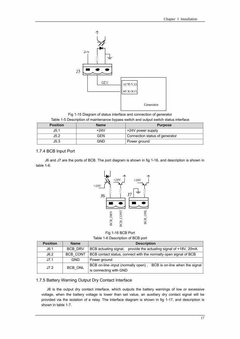
Chapter 1 Installation
17
Fig 1-15 Diagram of status interface and connection of generator
Table 1-5 Description of maintenance bypass switch and output switch status interface
Position Name Purpose
J51 +24V +24V power supply
J52 GEN Connection status of generator
J53 GND Power ground
174 BCB Input Port
J6 and J7 are the ports of BCB The port diagram is shown in fig 1-16 and description is shown in
table 1-6
BC
B_D
RV
BC
B_C
ON
T
J6 J7
BC
B_O
NL
+24V+24V
+24V
Fig 1-16 BCB Port
Table 1-6 Description of BCB port
Position Name Description
J61 BCB_DRV BCB actuating signal provide the actuating signal of +18V 20mA
J62 BCB_CONT BCB contact status connect with the normally open signal of BCB
J71 GND Power ground
J72 BCB_ONL BCB on-linendashinput (normally open) BCB is on-line when the signal
is connecting with GND
175 Battery Warning Output Dry Contact Interface
J8 is the output dry contact interface which outputs the battery warnings of low or excessive
voltage when the battery voltage is lower than set value an auxiliary dry contact signal will be
provided via the isolation of a relay The interface diagram is shown in fig 1-17 and description is
shown in table 1-7
Generator
Chapter 1 Installation
18
Fig 1-17 Battery warning dry contact interface diagram
Table 1-7 Battery warning dry contact interface description Position Name Purpose
J81 BAT_LOW_NC Battery warning relay (normally closed) will be open during warning
J82 BAT_LOW_NO Battery warning relay (normally open) will be closed during warning
J83 GND Center of battery warning relay
176 Integrated Warning Output Dry Contact Interface
J9 is the integrated warning output dry contact interface when one or more than one preset
warning is triggered the system will send an integrated warning information and provide an auxiliary
dry contact signal via the isolation of a relay The interface diagram is shown in fig 1-18 and description
is shown in table 1-8
Fig 1-18 Integrated warning dry contact interface diagram
Table 1-8 Integrated warning dry contact interface description Position Name Purpose
J91 ALARM_NC Integrated warning relay (normally closed) will be open during warning
J92 ALARM_NO Integrated warning relay (normally open) will be closed during warning
J93 GND Centre of integrated warning relay
177 Mains Failure Warning Output Dry Contact Interface
J10 is the output dry contact interface for mains failure warning when the mains fails the system
will send a mains failure warning information and provide an auxiliary dry contact signal via the isolation
of a relay The interface diagram is shown in fig 1-19 and description is shown in table 1-9
Chapter 1 Installation
19
Fig 1-19 Mains failure warning dry contact interface diagram
Table 1-9 Mains failure warning dry contact interface description Position Name Purpose
J91 UTI_FAIL_NC Mains failure warning relay(normally closed) will be open during
warning
J92 UTI_FAIL_NO Mains failure warning relay normally open) will be closed during
warning
J93 GND Centre of mains failure warning relay
178 RS232 Port and SNMP Card Port
RS232 and RS485 Port provide serial data which can be used for commissioning and maintenance
by authorized engineers or maintainers or can be used for networking or integrated monitoring system in
the service room
SNMP Card Port used for field installation of the communication option card(SNMP card)
179 LBS (Load Bus Synchronizer) Port
The dual bus system (DBS) consists of two independent UPS rack module systems as shown in fig
1-20 The dual bus system is configured for high availability and is suitable for powering the load with
dual inputs If the load is single-input load the static transfer switch and LBS control is recommended to
maintain both UPS outputs synchronized for uninterrupted transfers Please install the system according
to the installation descriptions for different system configurations
The dual bus system is supported by UPS it requires connecting the LBS signal cables of two UPS
when constructing the dual bus system please refer to relevant chapter for detailed configuration and
installation and the system software shall be configured as required
UPS 1
LBS
监控旁路模块 UPS 2
LBS
监控旁路模块
Fig 1-20 LBS Connection Diagram
18 Installation Drawing
Please refer to fig 1-21 fig 1-22 fig 1-23 and fig 1-24
UPS 1 monitoring bypass module
UPS 2 monitoring bypass module
Chapter 1 Installation
20
Fig 1-21 Installation Diagram
Chapter 1 Installation
21
顶视图
2m cabinet front view
16 m cabinet (front view)
Fig 1-22 UPS front view (Unit mm)
Top view
Chapter 1 Installation
22
A
2m cabinet
A
16m cabinet
Fig 1-23 UPS back view
Chapter 1 Installation
23
A
A处放大
Fig 1-24 UPS front view
Amplification of A
24 Chapter 2 Operations
24
Chapter 2 Operations
This chapter introduces the basic knowledge of UPS operations including working principle
operation mode battery management and protection
Warning Hazardous mains voltage andor battery voltage present(s)behind the protective cover
The components that can only be accessed by opening the protective cover with tools cannot be
operated by user
Only qualified service personnel are authorized to remove such covers
21 Introduction
UPS provides the critical load (such as communication and data processing equipment) with high
quality uninterruptible AC power The power from UPS is free from voltage and frequency variations and
disturbances (interruption and spike) experienced at the Mains AC input supply
This is achieved through high frequency double conversion power pulse width modulation (PWM)
associated with full digital signal processing control (DSP) which features high reliability and
convenience for use
211 Principle
As shown in fig 2-1 the AC input mains source is supplied at UPS input and converted into a DC
source This DC source feeds the Inverter that converts the DC source into a clean and input
independent AC source The battery powers the load through the inverter in case of an AC input mains
power failure The utility source can also power the load through the static bypass
When the UPS needs maintenance or repair the load can be transferred to maintenance bypass
without interruption and the power module and bypass module can be removed for maintenance
Chapter 2 Operations 25
25
Fig 2-1 System principle framework
212 Bypass Module
The circuit blocks labeled ldquobypass modulerdquo in fig 2-1 contain electronically controlled switching
circuits that enable the critical load to be connected to either the inverter output or to a bypass power
source via the static bypass line During normal system operation the load is connected to the inverter
but in the event of a UPS overload or inverter failure the load is automatically transferred to the static
bypass line
To provide a clean (no-break) load transfer between the inverter output and static bypass line the
inverter output and bypass supply must be fully synchronized during normal operating conditions This is
achieved through the inverter control electronics which makes the inverter frequency track that of the
static bypass supply provided that the bypass remains within an acceptable frequency window
A manually controlled maintenance bypass supply is incorporated into the UPS design It enables
the critical load to be powered from the utility (bypass) supply while the UPS is shut down for routine
maintenance
Note
When the UPS is operating in bypass mode or on maintenance bypass the connected equipment is
not protected from power failures or surges and sags
22 Operation Mode
The MD UPS is an on-line double-conversion reverse-transfer UPS that permits operation in these
modes
Normal mode
26 Chapter 2 Operations
26
Battery mode
Auto-Restart mode
Bypass mode
Maintenance mode (manual bypass)
ECO mode
Frequency converters mode
221 Normal Mode
The UPS inverter power modules continuously supplies the critical AC load The rectifiercharger
derives power from the AC mains input source and supplies DC power to the inverter while
simultaneously FLOAT or BOOST charging its associated backup battery
222 Battery Mode
Upon failure of the AC mains input power the inverter power modules which obtains power from the
battery supplies the critical AC load There is no interruption in power to the critical load upon failure
After restoration of the AC mains input power the ldquoNormal Moderdquo operation will continue automatically
without the necessity of user intervention
Note UPS can also be started through battery (charged) mode via battery cold start function upon
failure of the AC mains Therefore the battery power can be used independently to improve the
utilization rate of UPS
223 Auto-Restart Mode
The battery may become exhausted following an extended AC mains failure The inverter shuts
down when the battery reaches the End of Discharge voltage (EOD) The UPS may be programmed to
ldquoAuto Recovery after EODrdquo after a delay time if the AC mains recovers This mode and any delay time
are programmed by the commissioning engineer
During the process of delay time the battery will be charged by UPS to prevent any risks to load
equipment from future mains failure
224 Bypass Mode
If the inverter overload capacity is exceeded under normal mode or if the inverter becomes
unavailable for any reason the static transfer switch will perform a transfer of the load from the inverter
to the bypass source with no interruption in power to the critical AC load
225 Maintenance Mode
A manual bypass switch is available to ensure continuity of supply to the critical load when the UPS
becomes unavailable eg during a maintenance procedure
Note This manual bypass switch is fitted in all UPS modules Transfer UPS system to bypass
module for power supply first then close maintenance bypass switch Q2 followed by Q1 and Q3
Warning hazard may occur after transferring to maintenance bypass
After UPS being transferred to maintenance bypass power module and bypass module do not work
no display on LCD and input and output terminals as well as N bus are electrically connected
Chapter 2 Operations 27
27
226 ECO Mode
If economical (ECO) mode is selected the double-conversion UPS will stop to work so as to save
energy During the operation of ECO mode the load power will be supplied by bypass preferentially
When bypass power is within the range of normal frequency and voltage load power will be supplied by
bypass or the system will transfer to inverter input followed by load power interruption which extends
within 34 of the utility period Eg when the frequency is 50Hz the interruption time will be less than
15ms when the frequency is 60Hz the time will be less than 125ms
227 Frequency Converters Mode
If the frequency converter configuration is used by UPS it will provide 50Hz or 60Hz stable output
frequency The range of output frequency is 40Hz~70Hz Under this mode static bypass is unavailable
but battery can be selected according to the actual requirements of battery mode
23 Battery Management
231 Normal Function
The following functions should be fitted by commissioning engineers with specified software
1 Constant current boost charging
Current can be set up
2 Constant voltage boost charging
Voltage of boost charging can be set as required by the type of battery
For Valve Regulated Lead Acid (VRLA) batteries maximum boost charge voltage should not
exceed 24V cell
3 Float charge
Voltage of float charging can be set as required by the type of battery
For VRLA float charge voltage should be between 22V to 23V
4 Float charge temperature compensation (optional)
A coefficient of temperature compensation can be set as required by the type of battery
5 End of discharge (EOD) protection
If the battery voltage is lower than the EOD the battery converter will shut down and the battery is
isolated to avoid further battery discharge EOD is adjustable from 16V to 175V per cell (VRLA) or 09
to 11 V per cell
6 Battery low warning time
It is adjustable between 3 and 60 minutes The default is 5 minutes
232 Advanced Functions (Battery Self-checking and Maintenance)
At periodic intervals 20 of the rated capacity of the battery will be discharged automatically and
the actual load must exceed 20 of the rated UPS (KVA) capacity If the load is less than 20
auto-discharge cannot be executed The periodic interval can be set from 30 to 360 days The battery
self-test can be disabled
ConditionsmdashBattery at float charge for at least 5 hours load equal to 20~100 of rated UPS capacity
TriggermdashManually through the command of ldquoBattery Maintenance Testrdquo in LCD panel or automatically
Battery Self-Test Intervalmdash30-360 days (default setting is battery self-test disabled)
28 Chapter 2 Operations
28
24 Battery Protection
The following functions should be fitted by commissioning engineers with specified software
1 Battery Low Pre-warning
The battery under voltage pre-warning occurs before the end of discharge After this pre-warning
the battery should have the capacity for 3 remaining minutes discharging with full load The time is user
configured from 3 to 60 minutes
2 Battery discharge (EOD)off protection
If the battery voltage is lower than the EOD the battery converter will be shut down EOD is
adjustable from 16V to 175V per cell (VRLA) or 09 to 11 V per cell (NiCd)
3 Battery Circuit Breaker (BCB) Alarm
The alarm occurs when the battery disconnect device disconnects The external battery connects to
the UPS through the external battery circuit breaker The circuit breaker is manually closed and tripped
by the UPS control circuit
Chapter 3 Operation Instructions 29
29
Chapter 3 Operating Steps
This chapter describes UPS operation instructions in detail
All functional keys and LED display involved in operation instructions please refer to chapter 4
During operation the buzzer alarm may occur at any time Select ldquomuterdquo on LED to muffle the audible
alarm
Warning-Hazardous mains voltage andor battery voltage present(s)behind the protective cover
1 The components that can only be accessed by opening the protective cover with tools cannot be
operated by user
2 Only qualified service personnel are authorized to remove such covers
31 Power Switches
As shown in fig 3-1 open the front door of UPS the power switch is visible which includes input
switch output switch and maintenance bypass switch (with anti-misoperation stop plate)
输入开关 输出开关
维修旁路开关
Fig 3-1 Power switch location diagram
32 UPS Start-up
The UPS system only has a maintenance bypass isolating switch and all the other transfers are
processed automatically by internal control logics
Input switch Output switch
Maintenance bypass switch
30 Chapter 3 Operating Instructions
30
321 Normal Module Start
This procedure must be followed when turning on the UPS from a fully powered down condition
The operating procedures are as follows
Warning
This procedure results in mains voltage being applied to the UPS output terminals If any load
equipment is connected to the UPS output terminals please check with the load user that it is safe to
apply power If the load is not ready to receive power then ensure that it is safely to close the output
switch of external distribution cabinet
1 Close UPS output switch and input switch in turns
The LCD starts up at this time The Rectifier indicator flashes during the startup of rectifier The
rectifier enters normal operation state and after about 30s the rectifier indicator goes steady green After
initialization the bypass static switch closes The UPS Mimic LEDs will indicate as shown in table 3-1
Table 3-1 Indicator status
LED Status
Rectifier indicator Green
Battery indicator Red
Bypass indicator Green
Inverter indicator Off
Load indicator Green
Status indicator Green
Note
The output circuit breaker must be closed first followed by input circuit breaker or the rectifier cannot
be started and alarm ldquorectifier failurerdquo
The inverter starts up at this time the inverter indicator flashes After the rectifier enters normal
operation state UPS power supply will transfer from bypass to inverter then the bypass indicator turns
off and load indicator lights The status of indicators is shown in table 3-2
Table 3-2 Indicator Status
LED Status
Rectifier indicator Green
Battery indicator Red
Bypass indicator Off
Inverter indicator Green
Load indicator Green
Status indicator Green
Close external battery switch again battery indicator turns off a few minutes later the battery will be
charged by UPS which will enter normal mode operation The indicator status is shown in table 3-3
Table 3-3 Indicator status
LED Status
Rectifier indicator Green
Battery indicator Green
Bypass indicator Off
Inverter indicator Green
Load indicator Green
Status indicator Green
322 Operating steps of Battery cold Start
1 Check if the batteries have been connected close the external battery switch
Chapter 3 Operation Instructions 31
31
2 Press the red start-up button of battery under the rectifier input circuit breaker for 3 seconds (see fig
3-2)
The LCD starts up at this time The green battery indicator flashes The rectifier enters normal
operation states and after about 30s the battery indicator goes steady green
3 The inverter starts up automatically the green inverter indicator flashes The output of inverter
appears after 60s The UPS works on battery mode
32 Chapter 3 Operating Instructions
32
电池启动按钮
Fig 3-2 Position diagram of battery startup button
Battery startup button
Chapter 3 Operation Instructions 33
33
33 Procedure for Switching between Operation Modes
331 Procedure for Switching the UPS into Battery mode from Normal Mode
Open input switch to cut off the mains UPS enters the battery mode If UPS should be switched to
normal mode wait for a few seconds before close input switch so as to supply the mains again 10s
later the rectifier will start up automatically to supply power to the inverter
332 Procedure for Switching the UPS into Bypass mode from Normal Mode
Select ldquoTran Byprdquo on the LCD or press ldquooffrdquo buttons of each power module in turn
Note
In bypass mode the load is directly fed by the mains power instead of the pure AC power from the
inverter
333 Procedure for Switching the UPS into Normal from Bypass Mode
Select exit bypass mode on the LCD
334 Procedure for Switching the UPS into a Maintenance Bypass from Normal Mode
In normal operation this operation instruction will switch the load from inverter input to maintenance
bypass
Caution
Before making this operation read messages on display to be sure that bypass supply is regular and
the inverter is synchronous with it so as not to have a risk of a short interruption in powering the load
1 Press ldquoTran Byprdquo on the LCD or press ldquooffrdquo on each power module in turns
If press rdquoTran Byprdquo on the LCD the inverter indicator will flash green and the buzzer will alarm
If press ldquooffrdquo on each power module in turns the inverter indicator will go off and the buzzer will
alarm
The load will be transferred to static bypass and the inverter is closed
2 Close maintenance bypass switch Q2 the load power will be supplied by maintenance bypass and
then open the inverter circuit breaker Q1 output switch Q3 and battery switch
Warning
If you need to maintain the module wait for 10 minutes to let the DC bus capacitor fully discharge
before removing corresponding module
335 Procedure for Switching the UPS into Normal from a Maintenance Bypass Mode
This procedure can transfer the load to normal main mode when the UPS is operating under the
maintenance bypass mode
1 Close output switch Q3 and main switch Q1
The bypass indicator goes green and the load power will be supplied by bypass and maintenance
bypass
2 Open maintenance bypass switch Q2
34 Chapter 3 Operating Instructions
34
The load power is supplied by bypass In the meantime the rectifier starts up rectifier indicator goes
green 30s later at this time the inverter will start up automatically and transfer to inverter mode 1 min
later automatically
3 Close external battery switch the battery indicator goes off Check if the battery voltage on LCD
display is normal
34 Procedure for Completely Powering down a UPS
If you need to power down the UPS completely follow the procedures in section 334 to transfer the
UPS from normal mode to maintenance bypass mode
If you need to isolate the UPS from the AC power supply you should open the external input switch
35 EPO Procedure
The EPO button on UPS operator control and display panel is designed to switch off the UPS in
emergency conditions (eg fire flood etc)To achieve this just press the EPO button and the system
will turn off the rectifier inverter and stop powering the load immediately (including the inverter and
bypass output) and the battery stops charging or discharging
If the input utility is present the UPS control circuit will remain active however the output will be
turned off To completely isolate the UPS you need to open the external mains input supply to the UPS
rack
36 Language Selection
The LCD is available in two languages Chinese English and Korean
The language can be selected through LCD prompt window
37 Control Password
When the LCD displays ldquoinput control password 1rdquo the initial password is 12345678
Chapter 4 Operator Control and Display Panel 35
35
Chapter 4 Operator Control and Display Panel
This chapter introduces the functions and operation instructions of the parts on UPS operator control
and display panel in detail and provides LCD display information including LCD display types detailed
menu information prompt window information and UPS alarm list
41 Introduction
The operator control and display panel is located on the front panel of the UPS Through this LCD
panel the operator can operate and control the UPS and check all measured parameters UPS and
battery status and event and alarm logs The operator control panel is divided into three functional areas
as shown in fig 4-1 mimic current path LCD display amp Menu keys and Control and Operation Keys The
detailed description of parts on operator control and display panel is shown in table 4-1
Fig 4-1 UPS operator control and display panel
Table 4-1 Description of UPS operator control and display panel
Part No Function Button Function
REC Rectifier indicator EPO EPO switch
BAT Battery indicator TAB switch
BYP Bypass indicator ENTER confirm
INV Inverter indicator ESC exit
OUTPUT Load indicator
STATUS Status indicator
36 Chapter 4 Operator Control and Display Panel
36
411 LED Indicator
The LEDs shown on the mini current path represent the various UPS power paths and show the
current UPS operating status The status description of indicators is shown in table 4-2
Table 4-2 Status description of indicator
Indicator State Purpose
Rectifier
indicator
Steady green Rectifier normal for all modules
Flashing green Rectifier for at least on module normal mains normal
Steady red Rectifier fault
Flashing red Mains abnormal for at least one module
Off Rectifier not operating
Battery
indicator
Steady green Battery charging
Flashing green Battery discharging
Steady red
Battery abnormal (battery failure no battery or battery reverse) or
battery converter abnormal (failure over current or over temperature)
EOD
Flashing red Battery low voltage
Off Battery and battery converter normal battery not charging
Bypass
indicator
Steady green Load power supplied by bypass
Steady red Bypass power abnormal or out of normal range or static bypass
switch fault
Flashing red Bypass voltage abnormal
Off Bypass normal
Inverter
indicator
Steady green Load power supplied by inverter
Flashing green Inverter On start synchronization of standby (ECO mode) for at least
one module
Steady red System power not supplied by inverter inverter fault for at least one
module
Flashing red System power supplied by inverter inverter fault for at least one
module
Off Inverter not operating for all modules
Load
indicator
Steady green UPS output ON and normal
Steady red UPS output overload and overtime or output short or output no power
supply
Flashing red Overload output of UPS
Off No output of UPS
Status
indicator
Steady green Normal operation
Steady red Failure
412 Audible Alarm (buzzer)
There are two different types of audible alarm during UPS operation as shown in table 4-3
Table 4-3 description of audible alarm
Alarm Purpose
Two short alarm with
a long one
when system has general alarm (for example AC fault) this audible alarm
can be heard
Continuous alarm When system has serious faults (for example fuse or hardware fault) this
audible alarm can be heard
Chapter 4 Operator Control and Display Panel 37
37
413 Functional Keys
There are 4 functional keys on operator control and display panel which are used together with LCD
The functions description is shown in table 4-4
Table 4-4 Functions of functional keys
Functional key Functions
EPO switch To cut off the load power to shut down the rectifier inverter static
bypass and battery
TAB switch
ENTER confirm
ESC exit
42 LCD Display Type
Following the self-check of UPS LCD display the main LCD display is shown as fig 4-2 which can
be divided into three display windows system information data command and current record
Fig 4-2 Main LCD display
The description of LCD icon is shown in table 4-5
Table 4-5 Description of LCD icons
Icon Description
Bypass parameter
UPS system
information
window
Data
command
window
Current
record
window
38 Chapter 4 Operator Control and Display Panel
38
Icon Description
Main input parameter
History file system information
Function setting (display calibration password setting time setting date format
communication protocol and language setting) system setting (used by product
maintainers)
Battery data battery parameter setting (used by service staff)
Test (battery self-test battery maintenance)
Functional keys used by service staff (fault clearing history file clearing noise
clearing manual switch of bypass) userrsquos setting (system mode machine
number system ID output voltage adjustment frequency tracing speed
frequency tracing limit)
Output parameter
Load
Noise clearing noise clearing cancel
Log view page updown
Select a icon on LCD as shown in fig 4-3 to view the UPS parameter represented by this icon eg
select the LCD will display the data of system main input
Chapter 4 Operator Control and Display Panel 39
39
Fig 4-3 Select data
Or select and confirm a module as shown in fig 4-4 the LCD will display the
operating status of this module
Fig 4-4 Select a module
40 Chapter 4 Operator Control and Display Panel
40
Select in the operating status of a module to view the main input data of this module
Select in the operating status of a module to view the main output data of this module
Select in the operating status of a module to view the load data of this module
Select in the operating status of a module to view the maintenance code and module
software code of this module
Select to return to the previous page
Select to return to the home page
Default display
During the operation of system if therersquos no alarm in 2 min the system will display default After a
short delay the backlight of LCD display goes off press any key to reactivate the display
43 Detailed Description of Menu Items
The LCD main display shown in fig 4-2 is described in details below
UPS information window
UPS information window display the current time and UPS name The information of the window is
not necessary for the user to operate The information of this window is given in table 4-6
Table 4-6 Description of items in UPS system information window
Display contents Meaning
MD12020 UPS Name
1200 Current Time (format 24 hours hours minute)
UPS menu and data window
UPS menu window displays the menu name of data window while the data window displays the
related contents of selected menu in menu window Select UPS menu and data window to browse
related parameters of UPS and set related functions The details are given in table 4-7
Table 4-7 Item description of UPS menu and data window
Menu name Menu item Meaning
Main input
V phase(V) V phase
I phase(A) I phase
Freq(Hz) Input frequency
PF Power factor
Bypass input
V phase(V) V phase
Freq (Hz) Bypass frequency
I phase(A) I phase
PF Power factor
AC output
V phase(V) V phase
I phase(A) I phase
Freq (Hz) Output frequency
PF Power factor
This UPS Sout (kVA) Sout Apparent Power
Chapter 4 Operator Control and Display Panel 41
41
Menu name Menu item Meaning
modulersquos
load
Pout (kW) Pout Active Power
Qout (kVAR) Qout Reactive Power
Load () Load (The percentage of the UPS rating load)
Battery data
Environmental
Temp Environmental Temp
Battery
voltage(V) Battery bus voltage
Battery current
A) Battery bus current
Battery
Temp() Battery Temp
Remaining Time
(Min) Remaining battery backup time
Battery capacity
() The percentage compared with new battery capacity
battery
equalized
charging
Battery is equalized charging
battery float
charging Battery is float charging
Battery
disconnected Battery is not connected
Current
record (current alarm)
Display all current alarm The alarm list displayed on LCD of
UPS operator control and display panel please refer to table 4-9
History
record (history alarm)
Display all history alarm The alarm list displayed on LCD of
UPS operator control and display panel please refer to table 4-9
Menu
Language
(language
option) 2 languages can be selected
Settings
Display
calibration Adjust the accuracy of LCD display
Date format set MM DD YYYY and YYYY MM DD formats can be selected
Date amp Time DateTime set
Language set User can set the language (Chinese and English)
Communication
mode
Set communication mode MODBUS Power protocol and
company custom protocol modes can be selected Power
protocol mode can be divided into equipment address baud
rate set MODBUS protocol mode can be divided into
communication mode (RTUASCⅡ) equipment address
baud rate and check-bit set Company custom protocol mode
is the customed protocol of the company no option is
available
Control
password set User can modify control password 1
Test
Command
(Battery Test
Control
Battery
maintenance
test
This test will lead to the battery being partly discharged to
activate battery at the same time the approximate battery
capacity will be obtained Bypass must be in normal condition
the battery capacity should be above 25
42 Chapter 4 Operator Control and Display Panel
42
Menu name Menu item Meaning
Battery
self-check test
UPS switches to battery discharge for discharging to test if the
battery is normal Bypass must be in normal condition the
battery capacity should be above 25
Stop testing Manually Stop the test including maintenance test capacity test
UPS system
information
Monitoring
software version Provide monitoring software version
Rectified
software version Provide rectified software version
Inverted
software version Provide inverted software version
Serial No The serial no set when delivery from the factory
Rated
information Network setting of system operating
Module type Type of the module
44 Alarm List
The follow table 4-8 gives the complete list of all the UPS events displayed by history record window
and current record window
Table 4-8 Alarm List
Alarm Explanation
UPS power supply The system is in normal inverted power supply status
Bypass power
supply The system is in bypass power supply status
No power supply System no output
Battery equalized
charging Battery is in boost charging
Battery float
charging Battery is in float charging
Battery discharging The system is operating in battery discharging status
Battery connected Battery is connected
Battery
disconnected Battery is not connected
Maintenance circuit
breaker close Maintenance circuit breaker is close
Maintenance circuit
breaker open Maintenance circuit breaker is open
Emergency
shutdown System emergency shutdownEPO
Generator
connected External generator is connected
Mains abnormal Input mains abnormal
Bypass phase
conversion Bypass input phase converse
Bypass voltage
abnormal Bypass input voltage abnormal
Bypass fault Bypass fault
Bypass overload Bypass output is overload
Up to bypass
overtime of Bypass is overtime of overload
Chapter 4 Operator Control and Display Panel 43
43
Alarm Explanation
overload
Bypass frequency
tracing exceeds Bypass frequency is out of the tracing range
Switch times up to
in this hour
The times of switch between bypass and inverter exceeds 5 times in the latest
hour
Output short System output short
Battery EOD Battery voltage achieves shutdown point
Battery self-check The system enters battery self-check mode
Battery self-check
success Battery normal during system self-check
Battery manual
check failure Battery fault during system self-check
Battery
maintenance The system is in battery maintenance status
Battery
maintenance
success
Battery maintenance status completes
Battery
maintenance failure Battery maintenance process is not normal
Stop testing Battery self-check or battery maintenance status stops
Fault clearing Clear the alarmed fault
Delete history
record Delete all history record
N communication
node connected N module is connected to UPS system
N communication
node disconnected N module is not connected to UPS system
N rectifier fault N module rectifier fault
N inverter fault N module inverter fault
N rectifier
overheat N module rectifier overheat
N fan fault N module fan fault
N output overload N module output overload
N overtime of
overload N module output overtime of overload
N inverter
overheat N module inverter overheat
Inverter power
supply ban Inverter power ban supply
Manual switch of
bypass Switch the system to bypass output manually
Cancel manual
switch of bypass Switch the system from bypass to inverter output manually
Battery low voltage Battery low voltage
Battery reversal Battery polarity reversal
N inverter
protection N module inverter protection
Input N line
disconnected System input N line is not connected
Bypass fan fault Bypass module fan fault
N manual N module manual power off
44 Chapter 4 Operator Control and Display Panel
44
Alarm Explanation
shutdown
Chapter 5 Maintenance 45
45
Chapter 5 Installation of Parallel Operation System
The parallel operation system is installed as required by the installation procedures of the single
system and this chapter
The single devices are put parallel and connected as shown in fig 5-1 and the difference between
the lengths of the output cables of the single devices is not more than 10m It is recommended to use an
external bypass cabinet to facilitate maintenance and system testing
Fig 5-1 Typical 1+N parallel operation system
Note when the load exceeds is the capacity of the single device the maintenance bypass
switch CB3 must be removed
The cables for the parallel operation provide double insulation shielding up to 30m long the control
cables for the parallel operation must be connected with all single devices to form a closed loop as
shown in fig5-2
Other power supplies
Rectifier
Charger Inverter Inverter
Output power supply
Load connected
Mains power input L1 L2 L3 N terminal
Mains power inputL1 L2 L3 N terminal
Rectifier
Charger
46 Chapter 5 Maintenance
46
Fig5-2 parallel cables
Chapter 5 Maintenance 47
47
Chapter 6 Maintenance
This chapter introduces UPS maintenance including the maintenance instructions of power module
monitoring bypass module and the change method of dust filter
61 Instruction to Power Bypass and Output Power Distribution
Module
611 Precautions
1 Only maintaining engineers can maintain the power module and monitoring bypass module
2 In principle the power module and bypass module should be disassembled from top to bottom so
as to prevent any inclination from high gravity centre of the cabinet
3 To ensure the safety before maintaining power module and bypass module be sure to use a
multimeter to measure the DC bus capacitor voltage and ensure the voltage is below 60V before
operation and use a multimeter to measure the voltage between operating parts and the earth to
ensure the voltage is lower than hazardous voltage ie DC voltage is lower than 60Vdc and AC
maximum Voltage is lower than 424Vac
4 Bypass module doesnrsquot support any hot insertion and extraction only when UPS is in maintenance
bypass mode or UPS is completely power off can the bypass module be disassembled
5 The module can be maintained 10 mins after extracting power module and bypass module which
can be inserted into the cabinet 10 mins later
612 Instruction to Power Module
Suppose UPS were in normal mode and bypass were normal a module shall be maintained at
first
1 Press OFF of the module with a pin point or other tiny matter the module will shut down
automatically and exit the system
Note ensure if the remaining module will be overload when exiting a module If therersquos any risk of
overload transfer the whole UPS system to bypass followed by other operations
2 Take off the fixing bolt on the two sides of front and back plate of power module 10 mins later
extract the module from the cabinet
3 After maintaining the module push the module into the equipment cabinet (the interval between
two modules shall be more than 10s) fix the screw on the two sides Then the module will be
connected to UPS system automatically
613 Instruction to Bypass Module
Suppose UPS were in normal mode and the bypass were normal
1 Select LCD touch screen manual switch of bypass the UPS power will be supplied by bypass
2 Close maintenance bypass switch the UPS power will be supplied by maintenance bypass
3 Open UPS output switch and input switch
4 Open external battery switch
48 Chapter 5 Maintenance
48
5 Take off the fixing bolt at the two sides of front board of bypass module extract the front cable
assembly of the module and extract the module from the cabinet
6 After maintaining the module insert the module into the cabinet tighten the screw at the two sides
and connect the front cable assembly of manufacturerrsquos module
7 Close UPS output switch and input switch in turn
2 mins later bypass indicator on the operator control and display panel lights on which indicates
the normal power supply of bypass
8 Open maintenance bypass switch the inverter starts automatically 60s later the UPS will transfer
to normal mode
62 Replacing Dust Screen (optional)
As shown in fig 5-1 there are 3~4 dust filters on the back of UPSrsquo front door each screen is held in
place by a bracket on either side of each filter The procedure of replacing each filter is as follows
1 Open the UPSrsquo front door and locate the filters on the back side of the front door
2 Remove one bracket
3 Remove the dust screen to be replaced and insert the clean one
4 Reinstall the bracket
防尘网固定条
Fig 5-1 Dust screen on the back side of UPS front door
Bracket
Dust screen
Appendix 2 Toxic or Hazardous Materials or Elements Identification Table 49
49
Chapter 7 Product Specification
This chapter provides UPS product specification
71 Applicable Standards
The UPS has been designed to conform to the following European and international standards
Table 6-1 Compliance with European and International Standards
Item Normative reference
General safety requirements for UPS
used in operator access areas EN50091-1-1IEC62040-1-1AS 62040-1-1
Electromagnetic compatibility (EMC)
requirements for UPS EN50091-2IEC62040-2AS 62040-2(C3)
Method of specifying the performance
and test requirements of UPS EN50091-3IEC62040-3AS 62040-3(VFI SS 111)
Note The above mentioned product standards incorporate relevant compliance clauses with generic
IEC and EN standards for safety (IECENAS60950) electromagnetic emission and immunity
(IECEN AS61000 series) and construction (IECENAS60146 series and 60950)
72 Environmental Characteristics
Table 6-2 Environmental Properties
Items Unit Requirements
Acoustic noise level at 1
meter dB 550
Altitude of Operation m le1000m above sea level derate power by 1 per 100m
between 1000m and 2000m
Relative Humidity RH 0 to 95 non condensing
Operating Temperature 0 to 40 deg Battery life is halved for every 10degC increase
above 20degC
UPS Storage-Transport
Temperature -20~70
Recommended Battery
Storage Temperature -20~30 (20degC for optimum battery storage)
73 Mechanical Characteristics
Table 6-3 Mechanical Properties
Cabinet Specification Unit MD6010 MD9015
MD12020
MD10010 MD15015
MD20020
Mechanical Dimension
WtimesDtimesH mm 600times900times1600 600times900times2000
Weight kg 151 182
Color NA Black
Protection Level
IEC(60529) NA IP20
50 Chapter 5 Maintenance
50
Module type Unit MU10 MU15 MU20
Mechanical Dimension
WtimesDtimesH mm 440times590times134
Weight kg 21 22 22
Color NA Black
74 Electrical Characteristics (Input Rectifier)
Table 6-4 Rectifier AC input (mains)
Items Unit Parameter
Rated AC Input
Voltage Vac
380400415(three-phase and sharing neutral with the
bypass input)
Input voltage range Vac -40~+25
Frequency2 Hz 5060(range 40Hz~70Hz)
Power factor kWkVA full load 099
THD THDI 3
75 Electrical Characteristics (Intermediate DC Link)
Table 6-5 Battery
Items Unit Parameters
Battery bus
voltage Vdc Nominal plusmn240V one-side range 198V~288V
Quantity of
lead-acid cells Nominal 40=[1 battery(12V) ] 240=[1 battery(2V) ]
Float charge
voltage Vcell(VRLA)
225Vcell(selectable from 22Vcell~235Vcell)
Constant current and constant voltage charge mode
Temperature
compensation mVcl -30(selectable from 0~-50 25 or 30 or inhibit)
Ripple voltage V float le1
Ripple current C10 le5
equalized
charge voltage VRLA
24Vcell(selectable from 230Vcell~245Vcell)
Constant current and constant voltage charge mode
final
discharging
voltage
Vcell(VRLA)
165Vcell(selectable from 160Vcell ~ 1750Vcell) 06C
discharge current
175Vcell (selectable from 165Vcell ~ 18Vcell) 015C
discharge current
(EOD voltage changes linearly within the set range according to
discharge current)
Battery Charge Vcell 24Vcell(selectable from 23Vcell~245Vcell)
Constant current and constant voltage charge mode
Battery
Charging Power
Max Current
kW 10 UPS capacity (selectable from 0~20 UPS capacity)
Appendix 2 Toxic or Hazardous Materials or Elements Identification Table 51
51
76 Electrical Characteristics (Inverter Output)
Table 6-6 Inverter Output (to important load)
Rated
capacity(kVA) Unit 10~200
Rated AC voltage1 Vac 380400415(three-phase four-wire and sharing neutral with the
bypass)
Freqency2 Hz 5060
overload
110 load 1 hour
125 load 10min
150 load 1min
>150 load 200ms
Fault current 340 short current limitation for 200ms
Non linear load
capability 3 100
Neutral current
capability 170
Steady state
voltage stability
plusmn1(balanced load)
plusmn15(100 imbalance load)
Transient voltage
response 4 plusmn5
THD <15(linear load) <5(non linear load3)
Synchronization -
Window Rated frequency plusmn2Hz(selectable plusmn1~plusmn5Hz)
Max change rate of
synch frequency Hzs 1 selectable 01~5
Inverter voltage
range V(ac) plusmn5
Note
1 Factory setting is 380V Commissioning engineers can set to 400V or 415V
2 Factory setting is 50Hz Commissioning engineers can set to 60Hz
3 EN50091-3(1458) peak value factor is 3 1
4 IEC62040-3EN50091-3 including 0~100~0 load transient the recovery time is half
circle to within 5 of stable output voltage
52 Chapter 5 Maintenance
52
77 Electrical Characteristics(Bypass Mains Input)
Table 6-7 Bypass Mains Input
Rated
capacity(kVA) Unit 60 90 100 120 150 200
Rated AC
Voltage1 Vac
380400415
three-phase four-wire sharing neutral with the rectifier input and providing neutral
reference for the output
Rated current A
91380V
87400V
83415V
136380V
130400V
124415V
151380V
144400V
138415V
182380V
174400V
166415V
227380V
216400V
207415V
302380V
288400V
276415V
Overload
125 load long term
130 load 1 hour
150 load 6min
1000 load 100ms
Superior
protection
bypass line
NA Thermal-magnetic breaker the capacity is 125 of rated current output
IEC60947-2 curve C
Current rating
of neutral cable A 17timesIn
Frequency2 Hz 5060
Switch time
(between
bypass and
inverter)
ms Synchronized switch le1ms
Bypass voltage
tolerance Vac
Upper limit +10+15or+20 default +20
Lower limit -10 -20 -30 or-40 default-20
(acceptable stable bypass voltage delay 10s)
Bypass
frequency
tolerance
plusmn25 plusmn5 plusmn10 or plusmn20 default plusmn10
Synchronizatio
n-Window Hz Rated frequencyplusmn2Hz (selectable from plusmn05Hz~plusmn5Hz)
Note
1 Factory setting is 400V Commissioning engineers can set to 380V or 415V
2 Factory setting is 50Hz Commissioning engineers can set to 60Hz For example UPS is set to frequency
inverter mode and then bypass status will be neglected
78 Efficiency
Table 6-8 Efficiency Loss and Air Exchange
Rated Efficiency (kVA) Unit 10~200kVA
Normal mode(dual conversion) 95
ECO mode 99
Battery discharging efficiency (DCAC) (battery at nominal voltage 480Vdc and full-rated linear load)
battery mode 95
Appendix 2 Toxic or Hazardous Materials or Elements Identification Table 53
53
Appendix A A Guidebook to Ordering and Selection of MU System
MD series UPS module can be divided into equipment cabinet and power module For the cabinet
lectotype please refer to the description in fig 6-1
Fig 6-1 Cabinet Selection
For single power module type please refers to the description in fig 6-2
Fig 6-2 Power Module Selection
Egg the requirements of a plant room are given below
The maximum power supply of the plant room is 120kVA however it is expected to be expanded to
200kVA in 3-5 years Therefore a 200kVA cabinet and 6 20kVA power module can be purchased to
constitute an uninterrupted 120kVA power system which can be expanded to 200kVA on-line The order
symbol is
1 set MD20020
6 set MU20
Option list
MD-SNMP card remote network monitoring card
MD-1600 dust filter dust screen for 16m cabinet
MD-2000 dust filter dust screen for 2m cabinet
Represents the capacity of a single power module
10 represents 10kVA
15 represents 15kVA
20 represents 20kVA
represents a single power module
Represents UPS system capacitypower module
06010 represents 60kVA10kVA
09015 represents 90kVA15kVA
12020 represents 120kVA20kVA
15015 represents 150kVA15kVA
20020 represents 200kVA20kVA
MD represents UPS cabinet
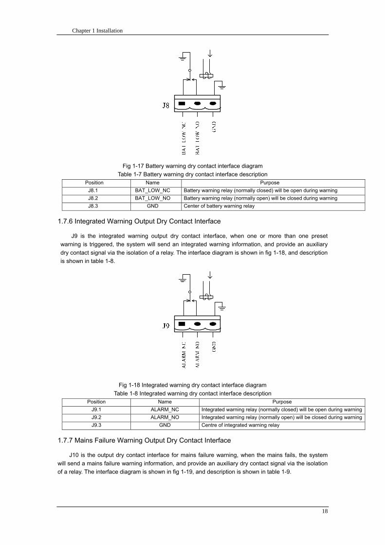
Chapter 1 Installation
18
Fig 1-17 Battery warning dry contact interface diagram
Table 1-7 Battery warning dry contact interface description Position Name Purpose
J81 BAT_LOW_NC Battery warning relay (normally closed) will be open during warning
J82 BAT_LOW_NO Battery warning relay (normally open) will be closed during warning
J83 GND Center of battery warning relay
176 Integrated Warning Output Dry Contact Interface
J9 is the integrated warning output dry contact interface when one or more than one preset
warning is triggered the system will send an integrated warning information and provide an auxiliary
dry contact signal via the isolation of a relay The interface diagram is shown in fig 1-18 and description
is shown in table 1-8
Fig 1-18 Integrated warning dry contact interface diagram
Table 1-8 Integrated warning dry contact interface description Position Name Purpose
J91 ALARM_NC Integrated warning relay (normally closed) will be open during warning
J92 ALARM_NO Integrated warning relay (normally open) will be closed during warning
J93 GND Centre of integrated warning relay
177 Mains Failure Warning Output Dry Contact Interface
J10 is the output dry contact interface for mains failure warning when the mains fails the system
will send a mains failure warning information and provide an auxiliary dry contact signal via the isolation
of a relay The interface diagram is shown in fig 1-19 and description is shown in table 1-9
Chapter 1 Installation
19
Fig 1-19 Mains failure warning dry contact interface diagram
Table 1-9 Mains failure warning dry contact interface description Position Name Purpose
J91 UTI_FAIL_NC Mains failure warning relay(normally closed) will be open during
warning
J92 UTI_FAIL_NO Mains failure warning relay normally open) will be closed during
warning
J93 GND Centre of mains failure warning relay
178 RS232 Port and SNMP Card Port
RS232 and RS485 Port provide serial data which can be used for commissioning and maintenance
by authorized engineers or maintainers or can be used for networking or integrated monitoring system in
the service room
SNMP Card Port used for field installation of the communication option card(SNMP card)
179 LBS (Load Bus Synchronizer) Port
The dual bus system (DBS) consists of two independent UPS rack module systems as shown in fig
1-20 The dual bus system is configured for high availability and is suitable for powering the load with
dual inputs If the load is single-input load the static transfer switch and LBS control is recommended to
maintain both UPS outputs synchronized for uninterrupted transfers Please install the system according
to the installation descriptions for different system configurations
The dual bus system is supported by UPS it requires connecting the LBS signal cables of two UPS
when constructing the dual bus system please refer to relevant chapter for detailed configuration and
installation and the system software shall be configured as required
UPS 1
LBS
监控旁路模块 UPS 2
LBS
监控旁路模块
Fig 1-20 LBS Connection Diagram
18 Installation Drawing
Please refer to fig 1-21 fig 1-22 fig 1-23 and fig 1-24
UPS 1 monitoring bypass module
UPS 2 monitoring bypass module
Chapter 1 Installation
20
Fig 1-21 Installation Diagram
Chapter 1 Installation
21
顶视图
2m cabinet front view
16 m cabinet (front view)
Fig 1-22 UPS front view (Unit mm)
Top view
Chapter 1 Installation
22
A
2m cabinet
A
16m cabinet
Fig 1-23 UPS back view
Chapter 1 Installation
23
A
A处放大
Fig 1-24 UPS front view
Amplification of A
24 Chapter 2 Operations
24
Chapter 2 Operations
This chapter introduces the basic knowledge of UPS operations including working principle
operation mode battery management and protection
Warning Hazardous mains voltage andor battery voltage present(s)behind the protective cover
The components that can only be accessed by opening the protective cover with tools cannot be
operated by user
Only qualified service personnel are authorized to remove such covers
21 Introduction
UPS provides the critical load (such as communication and data processing equipment) with high
quality uninterruptible AC power The power from UPS is free from voltage and frequency variations and
disturbances (interruption and spike) experienced at the Mains AC input supply
This is achieved through high frequency double conversion power pulse width modulation (PWM)
associated with full digital signal processing control (DSP) which features high reliability and
convenience for use
211 Principle
As shown in fig 2-1 the AC input mains source is supplied at UPS input and converted into a DC
source This DC source feeds the Inverter that converts the DC source into a clean and input
independent AC source The battery powers the load through the inverter in case of an AC input mains
power failure The utility source can also power the load through the static bypass
When the UPS needs maintenance or repair the load can be transferred to maintenance bypass
without interruption and the power module and bypass module can be removed for maintenance
Chapter 2 Operations 25
25
Fig 2-1 System principle framework
212 Bypass Module
The circuit blocks labeled ldquobypass modulerdquo in fig 2-1 contain electronically controlled switching
circuits that enable the critical load to be connected to either the inverter output or to a bypass power
source via the static bypass line During normal system operation the load is connected to the inverter
but in the event of a UPS overload or inverter failure the load is automatically transferred to the static
bypass line
To provide a clean (no-break) load transfer between the inverter output and static bypass line the
inverter output and bypass supply must be fully synchronized during normal operating conditions This is
achieved through the inverter control electronics which makes the inverter frequency track that of the
static bypass supply provided that the bypass remains within an acceptable frequency window
A manually controlled maintenance bypass supply is incorporated into the UPS design It enables
the critical load to be powered from the utility (bypass) supply while the UPS is shut down for routine
maintenance
Note
When the UPS is operating in bypass mode or on maintenance bypass the connected equipment is
not protected from power failures or surges and sags
22 Operation Mode
The MD UPS is an on-line double-conversion reverse-transfer UPS that permits operation in these
modes
Normal mode
26 Chapter 2 Operations
26
Battery mode
Auto-Restart mode
Bypass mode
Maintenance mode (manual bypass)
ECO mode
Frequency converters mode
221 Normal Mode
The UPS inverter power modules continuously supplies the critical AC load The rectifiercharger
derives power from the AC mains input source and supplies DC power to the inverter while
simultaneously FLOAT or BOOST charging its associated backup battery
222 Battery Mode
Upon failure of the AC mains input power the inverter power modules which obtains power from the
battery supplies the critical AC load There is no interruption in power to the critical load upon failure
After restoration of the AC mains input power the ldquoNormal Moderdquo operation will continue automatically
without the necessity of user intervention
Note UPS can also be started through battery (charged) mode via battery cold start function upon
failure of the AC mains Therefore the battery power can be used independently to improve the
utilization rate of UPS
223 Auto-Restart Mode
The battery may become exhausted following an extended AC mains failure The inverter shuts
down when the battery reaches the End of Discharge voltage (EOD) The UPS may be programmed to
ldquoAuto Recovery after EODrdquo after a delay time if the AC mains recovers This mode and any delay time
are programmed by the commissioning engineer
During the process of delay time the battery will be charged by UPS to prevent any risks to load
equipment from future mains failure
224 Bypass Mode
If the inverter overload capacity is exceeded under normal mode or if the inverter becomes
unavailable for any reason the static transfer switch will perform a transfer of the load from the inverter
to the bypass source with no interruption in power to the critical AC load
225 Maintenance Mode
A manual bypass switch is available to ensure continuity of supply to the critical load when the UPS
becomes unavailable eg during a maintenance procedure
Note This manual bypass switch is fitted in all UPS modules Transfer UPS system to bypass
module for power supply first then close maintenance bypass switch Q2 followed by Q1 and Q3
Warning hazard may occur after transferring to maintenance bypass
After UPS being transferred to maintenance bypass power module and bypass module do not work
no display on LCD and input and output terminals as well as N bus are electrically connected
Chapter 2 Operations 27
27
226 ECO Mode
If economical (ECO) mode is selected the double-conversion UPS will stop to work so as to save
energy During the operation of ECO mode the load power will be supplied by bypass preferentially
When bypass power is within the range of normal frequency and voltage load power will be supplied by
bypass or the system will transfer to inverter input followed by load power interruption which extends
within 34 of the utility period Eg when the frequency is 50Hz the interruption time will be less than
15ms when the frequency is 60Hz the time will be less than 125ms
227 Frequency Converters Mode
If the frequency converter configuration is used by UPS it will provide 50Hz or 60Hz stable output
frequency The range of output frequency is 40Hz~70Hz Under this mode static bypass is unavailable
but battery can be selected according to the actual requirements of battery mode
23 Battery Management
231 Normal Function
The following functions should be fitted by commissioning engineers with specified software
1 Constant current boost charging
Current can be set up
2 Constant voltage boost charging
Voltage of boost charging can be set as required by the type of battery
For Valve Regulated Lead Acid (VRLA) batteries maximum boost charge voltage should not
exceed 24V cell
3 Float charge
Voltage of float charging can be set as required by the type of battery
For VRLA float charge voltage should be between 22V to 23V
4 Float charge temperature compensation (optional)
A coefficient of temperature compensation can be set as required by the type of battery
5 End of discharge (EOD) protection
If the battery voltage is lower than the EOD the battery converter will shut down and the battery is
isolated to avoid further battery discharge EOD is adjustable from 16V to 175V per cell (VRLA) or 09
to 11 V per cell
6 Battery low warning time
It is adjustable between 3 and 60 minutes The default is 5 minutes
232 Advanced Functions (Battery Self-checking and Maintenance)
At periodic intervals 20 of the rated capacity of the battery will be discharged automatically and
the actual load must exceed 20 of the rated UPS (KVA) capacity If the load is less than 20
auto-discharge cannot be executed The periodic interval can be set from 30 to 360 days The battery
self-test can be disabled
ConditionsmdashBattery at float charge for at least 5 hours load equal to 20~100 of rated UPS capacity
TriggermdashManually through the command of ldquoBattery Maintenance Testrdquo in LCD panel or automatically
Battery Self-Test Intervalmdash30-360 days (default setting is battery self-test disabled)
28 Chapter 2 Operations
28
24 Battery Protection
The following functions should be fitted by commissioning engineers with specified software
1 Battery Low Pre-warning
The battery under voltage pre-warning occurs before the end of discharge After this pre-warning
the battery should have the capacity for 3 remaining minutes discharging with full load The time is user
configured from 3 to 60 minutes
2 Battery discharge (EOD)off protection
If the battery voltage is lower than the EOD the battery converter will be shut down EOD is
adjustable from 16V to 175V per cell (VRLA) or 09 to 11 V per cell (NiCd)
3 Battery Circuit Breaker (BCB) Alarm
The alarm occurs when the battery disconnect device disconnects The external battery connects to
the UPS through the external battery circuit breaker The circuit breaker is manually closed and tripped
by the UPS control circuit
Chapter 3 Operation Instructions 29
29
Chapter 3 Operating Steps
This chapter describes UPS operation instructions in detail
All functional keys and LED display involved in operation instructions please refer to chapter 4
During operation the buzzer alarm may occur at any time Select ldquomuterdquo on LED to muffle the audible
alarm
Warning-Hazardous mains voltage andor battery voltage present(s)behind the protective cover
1 The components that can only be accessed by opening the protective cover with tools cannot be
operated by user
2 Only qualified service personnel are authorized to remove such covers
31 Power Switches
As shown in fig 3-1 open the front door of UPS the power switch is visible which includes input
switch output switch and maintenance bypass switch (with anti-misoperation stop plate)
输入开关 输出开关
维修旁路开关
Fig 3-1 Power switch location diagram
32 UPS Start-up
The UPS system only has a maintenance bypass isolating switch and all the other transfers are
processed automatically by internal control logics
Input switch Output switch
Maintenance bypass switch
30 Chapter 3 Operating Instructions
30
321 Normal Module Start
This procedure must be followed when turning on the UPS from a fully powered down condition
The operating procedures are as follows
Warning
This procedure results in mains voltage being applied to the UPS output terminals If any load
equipment is connected to the UPS output terminals please check with the load user that it is safe to
apply power If the load is not ready to receive power then ensure that it is safely to close the output
switch of external distribution cabinet
1 Close UPS output switch and input switch in turns
The LCD starts up at this time The Rectifier indicator flashes during the startup of rectifier The
rectifier enters normal operation state and after about 30s the rectifier indicator goes steady green After
initialization the bypass static switch closes The UPS Mimic LEDs will indicate as shown in table 3-1
Table 3-1 Indicator status
LED Status
Rectifier indicator Green
Battery indicator Red
Bypass indicator Green
Inverter indicator Off
Load indicator Green
Status indicator Green
Note
The output circuit breaker must be closed first followed by input circuit breaker or the rectifier cannot
be started and alarm ldquorectifier failurerdquo
The inverter starts up at this time the inverter indicator flashes After the rectifier enters normal
operation state UPS power supply will transfer from bypass to inverter then the bypass indicator turns
off and load indicator lights The status of indicators is shown in table 3-2
Table 3-2 Indicator Status
LED Status
Rectifier indicator Green
Battery indicator Red
Bypass indicator Off
Inverter indicator Green
Load indicator Green
Status indicator Green
Close external battery switch again battery indicator turns off a few minutes later the battery will be
charged by UPS which will enter normal mode operation The indicator status is shown in table 3-3
Table 3-3 Indicator status
LED Status
Rectifier indicator Green
Battery indicator Green
Bypass indicator Off
Inverter indicator Green
Load indicator Green
Status indicator Green
322 Operating steps of Battery cold Start
1 Check if the batteries have been connected close the external battery switch
Chapter 3 Operation Instructions 31
31
2 Press the red start-up button of battery under the rectifier input circuit breaker for 3 seconds (see fig
3-2)
The LCD starts up at this time The green battery indicator flashes The rectifier enters normal
operation states and after about 30s the battery indicator goes steady green
3 The inverter starts up automatically the green inverter indicator flashes The output of inverter
appears after 60s The UPS works on battery mode
32 Chapter 3 Operating Instructions
32
电池启动按钮
Fig 3-2 Position diagram of battery startup button
Battery startup button
Chapter 3 Operation Instructions 33
33
33 Procedure for Switching between Operation Modes
331 Procedure for Switching the UPS into Battery mode from Normal Mode
Open input switch to cut off the mains UPS enters the battery mode If UPS should be switched to
normal mode wait for a few seconds before close input switch so as to supply the mains again 10s
later the rectifier will start up automatically to supply power to the inverter
332 Procedure for Switching the UPS into Bypass mode from Normal Mode
Select ldquoTran Byprdquo on the LCD or press ldquooffrdquo buttons of each power module in turn
Note
In bypass mode the load is directly fed by the mains power instead of the pure AC power from the
inverter
333 Procedure for Switching the UPS into Normal from Bypass Mode
Select exit bypass mode on the LCD
334 Procedure for Switching the UPS into a Maintenance Bypass from Normal Mode
In normal operation this operation instruction will switch the load from inverter input to maintenance
bypass
Caution
Before making this operation read messages on display to be sure that bypass supply is regular and
the inverter is synchronous with it so as not to have a risk of a short interruption in powering the load
1 Press ldquoTran Byprdquo on the LCD or press ldquooffrdquo on each power module in turns
If press rdquoTran Byprdquo on the LCD the inverter indicator will flash green and the buzzer will alarm
If press ldquooffrdquo on each power module in turns the inverter indicator will go off and the buzzer will
alarm
The load will be transferred to static bypass and the inverter is closed
2 Close maintenance bypass switch Q2 the load power will be supplied by maintenance bypass and
then open the inverter circuit breaker Q1 output switch Q3 and battery switch
Warning
If you need to maintain the module wait for 10 minutes to let the DC bus capacitor fully discharge
before removing corresponding module
335 Procedure for Switching the UPS into Normal from a Maintenance Bypass Mode
This procedure can transfer the load to normal main mode when the UPS is operating under the
maintenance bypass mode
1 Close output switch Q3 and main switch Q1
The bypass indicator goes green and the load power will be supplied by bypass and maintenance
bypass
2 Open maintenance bypass switch Q2
34 Chapter 3 Operating Instructions
34
The load power is supplied by bypass In the meantime the rectifier starts up rectifier indicator goes
green 30s later at this time the inverter will start up automatically and transfer to inverter mode 1 min
later automatically
3 Close external battery switch the battery indicator goes off Check if the battery voltage on LCD
display is normal
34 Procedure for Completely Powering down a UPS
If you need to power down the UPS completely follow the procedures in section 334 to transfer the
UPS from normal mode to maintenance bypass mode
If you need to isolate the UPS from the AC power supply you should open the external input switch
35 EPO Procedure
The EPO button on UPS operator control and display panel is designed to switch off the UPS in
emergency conditions (eg fire flood etc)To achieve this just press the EPO button and the system
will turn off the rectifier inverter and stop powering the load immediately (including the inverter and
bypass output) and the battery stops charging or discharging
If the input utility is present the UPS control circuit will remain active however the output will be
turned off To completely isolate the UPS you need to open the external mains input supply to the UPS
rack
36 Language Selection
The LCD is available in two languages Chinese English and Korean
The language can be selected through LCD prompt window
37 Control Password
When the LCD displays ldquoinput control password 1rdquo the initial password is 12345678
Chapter 4 Operator Control and Display Panel 35
35
Chapter 4 Operator Control and Display Panel
This chapter introduces the functions and operation instructions of the parts on UPS operator control
and display panel in detail and provides LCD display information including LCD display types detailed
menu information prompt window information and UPS alarm list
41 Introduction
The operator control and display panel is located on the front panel of the UPS Through this LCD
panel the operator can operate and control the UPS and check all measured parameters UPS and
battery status and event and alarm logs The operator control panel is divided into three functional areas
as shown in fig 4-1 mimic current path LCD display amp Menu keys and Control and Operation Keys The
detailed description of parts on operator control and display panel is shown in table 4-1
Fig 4-1 UPS operator control and display panel
Table 4-1 Description of UPS operator control and display panel
Part No Function Button Function
REC Rectifier indicator EPO EPO switch
BAT Battery indicator TAB switch
BYP Bypass indicator ENTER confirm
INV Inverter indicator ESC exit
OUTPUT Load indicator
STATUS Status indicator
36 Chapter 4 Operator Control and Display Panel
36
411 LED Indicator
The LEDs shown on the mini current path represent the various UPS power paths and show the
current UPS operating status The status description of indicators is shown in table 4-2
Table 4-2 Status description of indicator
Indicator State Purpose
Rectifier
indicator
Steady green Rectifier normal for all modules
Flashing green Rectifier for at least on module normal mains normal
Steady red Rectifier fault
Flashing red Mains abnormal for at least one module
Off Rectifier not operating
Battery
indicator
Steady green Battery charging
Flashing green Battery discharging
Steady red
Battery abnormal (battery failure no battery or battery reverse) or
battery converter abnormal (failure over current or over temperature)
EOD
Flashing red Battery low voltage
Off Battery and battery converter normal battery not charging
Bypass
indicator
Steady green Load power supplied by bypass
Steady red Bypass power abnormal or out of normal range or static bypass
switch fault
Flashing red Bypass voltage abnormal
Off Bypass normal
Inverter
indicator
Steady green Load power supplied by inverter
Flashing green Inverter On start synchronization of standby (ECO mode) for at least
one module
Steady red System power not supplied by inverter inverter fault for at least one
module
Flashing red System power supplied by inverter inverter fault for at least one
module
Off Inverter not operating for all modules
Load
indicator
Steady green UPS output ON and normal
Steady red UPS output overload and overtime or output short or output no power
supply
Flashing red Overload output of UPS
Off No output of UPS
Status
indicator
Steady green Normal operation
Steady red Failure
412 Audible Alarm (buzzer)
There are two different types of audible alarm during UPS operation as shown in table 4-3
Table 4-3 description of audible alarm
Alarm Purpose
Two short alarm with
a long one
when system has general alarm (for example AC fault) this audible alarm
can be heard
Continuous alarm When system has serious faults (for example fuse or hardware fault) this
audible alarm can be heard
Chapter 4 Operator Control and Display Panel 37
37
413 Functional Keys
There are 4 functional keys on operator control and display panel which are used together with LCD
The functions description is shown in table 4-4
Table 4-4 Functions of functional keys
Functional key Functions
EPO switch To cut off the load power to shut down the rectifier inverter static
bypass and battery
TAB switch
ENTER confirm
ESC exit
42 LCD Display Type
Following the self-check of UPS LCD display the main LCD display is shown as fig 4-2 which can
be divided into three display windows system information data command and current record
Fig 4-2 Main LCD display
The description of LCD icon is shown in table 4-5
Table 4-5 Description of LCD icons
Icon Description
Bypass parameter
UPS system
information
window
Data
command
window
Current
record
window
38 Chapter 4 Operator Control and Display Panel
38
Icon Description
Main input parameter
History file system information
Function setting (display calibration password setting time setting date format
communication protocol and language setting) system setting (used by product
maintainers)
Battery data battery parameter setting (used by service staff)
Test (battery self-test battery maintenance)
Functional keys used by service staff (fault clearing history file clearing noise
clearing manual switch of bypass) userrsquos setting (system mode machine
number system ID output voltage adjustment frequency tracing speed
frequency tracing limit)
Output parameter
Load
Noise clearing noise clearing cancel
Log view page updown
Select a icon on LCD as shown in fig 4-3 to view the UPS parameter represented by this icon eg
select the LCD will display the data of system main input
Chapter 4 Operator Control and Display Panel 39
39
Fig 4-3 Select data
Or select and confirm a module as shown in fig 4-4 the LCD will display the
operating status of this module
Fig 4-4 Select a module
40 Chapter 4 Operator Control and Display Panel
40
Select in the operating status of a module to view the main input data of this module
Select in the operating status of a module to view the main output data of this module
Select in the operating status of a module to view the load data of this module
Select in the operating status of a module to view the maintenance code and module
software code of this module
Select to return to the previous page
Select to return to the home page
Default display
During the operation of system if therersquos no alarm in 2 min the system will display default After a
short delay the backlight of LCD display goes off press any key to reactivate the display
43 Detailed Description of Menu Items
The LCD main display shown in fig 4-2 is described in details below
UPS information window
UPS information window display the current time and UPS name The information of the window is
not necessary for the user to operate The information of this window is given in table 4-6
Table 4-6 Description of items in UPS system information window
Display contents Meaning
MD12020 UPS Name
1200 Current Time (format 24 hours hours minute)
UPS menu and data window
UPS menu window displays the menu name of data window while the data window displays the
related contents of selected menu in menu window Select UPS menu and data window to browse
related parameters of UPS and set related functions The details are given in table 4-7
Table 4-7 Item description of UPS menu and data window
Menu name Menu item Meaning
Main input
V phase(V) V phase
I phase(A) I phase
Freq(Hz) Input frequency
PF Power factor
Bypass input
V phase(V) V phase
Freq (Hz) Bypass frequency
I phase(A) I phase
PF Power factor
AC output
V phase(V) V phase
I phase(A) I phase
Freq (Hz) Output frequency
PF Power factor
This UPS Sout (kVA) Sout Apparent Power
Chapter 4 Operator Control and Display Panel 41
41
Menu name Menu item Meaning
modulersquos
load
Pout (kW) Pout Active Power
Qout (kVAR) Qout Reactive Power
Load () Load (The percentage of the UPS rating load)
Battery data
Environmental
Temp Environmental Temp
Battery
voltage(V) Battery bus voltage
Battery current
A) Battery bus current
Battery
Temp() Battery Temp
Remaining Time
(Min) Remaining battery backup time
Battery capacity
() The percentage compared with new battery capacity
battery
equalized
charging
Battery is equalized charging
battery float
charging Battery is float charging
Battery
disconnected Battery is not connected
Current
record (current alarm)
Display all current alarm The alarm list displayed on LCD of
UPS operator control and display panel please refer to table 4-9
History
record (history alarm)
Display all history alarm The alarm list displayed on LCD of
UPS operator control and display panel please refer to table 4-9
Menu
Language
(language
option) 2 languages can be selected
Settings
Display
calibration Adjust the accuracy of LCD display
Date format set MM DD YYYY and YYYY MM DD formats can be selected
Date amp Time DateTime set
Language set User can set the language (Chinese and English)
Communication
mode
Set communication mode MODBUS Power protocol and
company custom protocol modes can be selected Power
protocol mode can be divided into equipment address baud
rate set MODBUS protocol mode can be divided into
communication mode (RTUASCⅡ) equipment address
baud rate and check-bit set Company custom protocol mode
is the customed protocol of the company no option is
available
Control
password set User can modify control password 1
Test
Command
(Battery Test
Control
Battery
maintenance
test
This test will lead to the battery being partly discharged to
activate battery at the same time the approximate battery
capacity will be obtained Bypass must be in normal condition
the battery capacity should be above 25
42 Chapter 4 Operator Control and Display Panel
42
Menu name Menu item Meaning
Battery
self-check test
UPS switches to battery discharge for discharging to test if the
battery is normal Bypass must be in normal condition the
battery capacity should be above 25
Stop testing Manually Stop the test including maintenance test capacity test
UPS system
information
Monitoring
software version Provide monitoring software version
Rectified
software version Provide rectified software version
Inverted
software version Provide inverted software version
Serial No The serial no set when delivery from the factory
Rated
information Network setting of system operating
Module type Type of the module
44 Alarm List
The follow table 4-8 gives the complete list of all the UPS events displayed by history record window
and current record window
Table 4-8 Alarm List
Alarm Explanation
UPS power supply The system is in normal inverted power supply status
Bypass power
supply The system is in bypass power supply status
No power supply System no output
Battery equalized
charging Battery is in boost charging
Battery float
charging Battery is in float charging
Battery discharging The system is operating in battery discharging status
Battery connected Battery is connected
Battery
disconnected Battery is not connected
Maintenance circuit
breaker close Maintenance circuit breaker is close
Maintenance circuit
breaker open Maintenance circuit breaker is open
Emergency
shutdown System emergency shutdownEPO
Generator
connected External generator is connected
Mains abnormal Input mains abnormal
Bypass phase
conversion Bypass input phase converse
Bypass voltage
abnormal Bypass input voltage abnormal
Bypass fault Bypass fault
Bypass overload Bypass output is overload
Up to bypass
overtime of Bypass is overtime of overload
Chapter 4 Operator Control and Display Panel 43
43
Alarm Explanation
overload
Bypass frequency
tracing exceeds Bypass frequency is out of the tracing range
Switch times up to
in this hour
The times of switch between bypass and inverter exceeds 5 times in the latest
hour
Output short System output short
Battery EOD Battery voltage achieves shutdown point
Battery self-check The system enters battery self-check mode
Battery self-check
success Battery normal during system self-check
Battery manual
check failure Battery fault during system self-check
Battery
maintenance The system is in battery maintenance status
Battery
maintenance
success
Battery maintenance status completes
Battery
maintenance failure Battery maintenance process is not normal
Stop testing Battery self-check or battery maintenance status stops
Fault clearing Clear the alarmed fault
Delete history
record Delete all history record
N communication
node connected N module is connected to UPS system
N communication
node disconnected N module is not connected to UPS system
N rectifier fault N module rectifier fault
N inverter fault N module inverter fault
N rectifier
overheat N module rectifier overheat
N fan fault N module fan fault
N output overload N module output overload
N overtime of
overload N module output overtime of overload
N inverter
overheat N module inverter overheat
Inverter power
supply ban Inverter power ban supply
Manual switch of
bypass Switch the system to bypass output manually
Cancel manual
switch of bypass Switch the system from bypass to inverter output manually
Battery low voltage Battery low voltage
Battery reversal Battery polarity reversal
N inverter
protection N module inverter protection
Input N line
disconnected System input N line is not connected
Bypass fan fault Bypass module fan fault
N manual N module manual power off
44 Chapter 4 Operator Control and Display Panel
44
Alarm Explanation
shutdown
Chapter 5 Maintenance 45
45
Chapter 5 Installation of Parallel Operation System
The parallel operation system is installed as required by the installation procedures of the single
system and this chapter
The single devices are put parallel and connected as shown in fig 5-1 and the difference between
the lengths of the output cables of the single devices is not more than 10m It is recommended to use an
external bypass cabinet to facilitate maintenance and system testing
Fig 5-1 Typical 1+N parallel operation system
Note when the load exceeds is the capacity of the single device the maintenance bypass
switch CB3 must be removed
The cables for the parallel operation provide double insulation shielding up to 30m long the control
cables for the parallel operation must be connected with all single devices to form a closed loop as
shown in fig5-2
Other power supplies
Rectifier
Charger Inverter Inverter
Output power supply
Load connected
Mains power input L1 L2 L3 N terminal
Mains power inputL1 L2 L3 N terminal
Rectifier
Charger
46 Chapter 5 Maintenance
46
Fig5-2 parallel cables
Chapter 5 Maintenance 47
47
Chapter 6 Maintenance
This chapter introduces UPS maintenance including the maintenance instructions of power module
monitoring bypass module and the change method of dust filter
61 Instruction to Power Bypass and Output Power Distribution
Module
611 Precautions
1 Only maintaining engineers can maintain the power module and monitoring bypass module
2 In principle the power module and bypass module should be disassembled from top to bottom so
as to prevent any inclination from high gravity centre of the cabinet
3 To ensure the safety before maintaining power module and bypass module be sure to use a
multimeter to measure the DC bus capacitor voltage and ensure the voltage is below 60V before
operation and use a multimeter to measure the voltage between operating parts and the earth to
ensure the voltage is lower than hazardous voltage ie DC voltage is lower than 60Vdc and AC
maximum Voltage is lower than 424Vac
4 Bypass module doesnrsquot support any hot insertion and extraction only when UPS is in maintenance
bypass mode or UPS is completely power off can the bypass module be disassembled
5 The module can be maintained 10 mins after extracting power module and bypass module which
can be inserted into the cabinet 10 mins later
612 Instruction to Power Module
Suppose UPS were in normal mode and bypass were normal a module shall be maintained at
first
1 Press OFF of the module with a pin point or other tiny matter the module will shut down
automatically and exit the system
Note ensure if the remaining module will be overload when exiting a module If therersquos any risk of
overload transfer the whole UPS system to bypass followed by other operations
2 Take off the fixing bolt on the two sides of front and back plate of power module 10 mins later
extract the module from the cabinet
3 After maintaining the module push the module into the equipment cabinet (the interval between
two modules shall be more than 10s) fix the screw on the two sides Then the module will be
connected to UPS system automatically
613 Instruction to Bypass Module
Suppose UPS were in normal mode and the bypass were normal
1 Select LCD touch screen manual switch of bypass the UPS power will be supplied by bypass
2 Close maintenance bypass switch the UPS power will be supplied by maintenance bypass
3 Open UPS output switch and input switch
4 Open external battery switch
48 Chapter 5 Maintenance
48
5 Take off the fixing bolt at the two sides of front board of bypass module extract the front cable
assembly of the module and extract the module from the cabinet
6 After maintaining the module insert the module into the cabinet tighten the screw at the two sides
and connect the front cable assembly of manufacturerrsquos module
7 Close UPS output switch and input switch in turn
2 mins later bypass indicator on the operator control and display panel lights on which indicates
the normal power supply of bypass
8 Open maintenance bypass switch the inverter starts automatically 60s later the UPS will transfer
to normal mode
62 Replacing Dust Screen (optional)
As shown in fig 5-1 there are 3~4 dust filters on the back of UPSrsquo front door each screen is held in
place by a bracket on either side of each filter The procedure of replacing each filter is as follows
1 Open the UPSrsquo front door and locate the filters on the back side of the front door
2 Remove one bracket
3 Remove the dust screen to be replaced and insert the clean one
4 Reinstall the bracket
防尘网固定条
Fig 5-1 Dust screen on the back side of UPS front door
Bracket
Dust screen
Appendix 2 Toxic or Hazardous Materials or Elements Identification Table 49
49
Chapter 7 Product Specification
This chapter provides UPS product specification
71 Applicable Standards
The UPS has been designed to conform to the following European and international standards
Table 6-1 Compliance with European and International Standards
Item Normative reference
General safety requirements for UPS
used in operator access areas EN50091-1-1IEC62040-1-1AS 62040-1-1
Electromagnetic compatibility (EMC)
requirements for UPS EN50091-2IEC62040-2AS 62040-2(C3)
Method of specifying the performance
and test requirements of UPS EN50091-3IEC62040-3AS 62040-3(VFI SS 111)
Note The above mentioned product standards incorporate relevant compliance clauses with generic
IEC and EN standards for safety (IECENAS60950) electromagnetic emission and immunity
(IECEN AS61000 series) and construction (IECENAS60146 series and 60950)
72 Environmental Characteristics
Table 6-2 Environmental Properties
Items Unit Requirements
Acoustic noise level at 1
meter dB 550
Altitude of Operation m le1000m above sea level derate power by 1 per 100m
between 1000m and 2000m
Relative Humidity RH 0 to 95 non condensing
Operating Temperature 0 to 40 deg Battery life is halved for every 10degC increase
above 20degC
UPS Storage-Transport
Temperature -20~70
Recommended Battery
Storage Temperature -20~30 (20degC for optimum battery storage)
73 Mechanical Characteristics
Table 6-3 Mechanical Properties
Cabinet Specification Unit MD6010 MD9015
MD12020
MD10010 MD15015
MD20020
Mechanical Dimension
WtimesDtimesH mm 600times900times1600 600times900times2000
Weight kg 151 182
Color NA Black
Protection Level
IEC(60529) NA IP20
50 Chapter 5 Maintenance
50
Module type Unit MU10 MU15 MU20
Mechanical Dimension
WtimesDtimesH mm 440times590times134
Weight kg 21 22 22
Color NA Black
74 Electrical Characteristics (Input Rectifier)
Table 6-4 Rectifier AC input (mains)
Items Unit Parameter
Rated AC Input
Voltage Vac
380400415(three-phase and sharing neutral with the
bypass input)
Input voltage range Vac -40~+25
Frequency2 Hz 5060(range 40Hz~70Hz)
Power factor kWkVA full load 099
THD THDI 3
75 Electrical Characteristics (Intermediate DC Link)
Table 6-5 Battery
Items Unit Parameters
Battery bus
voltage Vdc Nominal plusmn240V one-side range 198V~288V
Quantity of
lead-acid cells Nominal 40=[1 battery(12V) ] 240=[1 battery(2V) ]
Float charge
voltage Vcell(VRLA)
225Vcell(selectable from 22Vcell~235Vcell)
Constant current and constant voltage charge mode
Temperature
compensation mVcl -30(selectable from 0~-50 25 or 30 or inhibit)
Ripple voltage V float le1
Ripple current C10 le5
equalized
charge voltage VRLA
24Vcell(selectable from 230Vcell~245Vcell)
Constant current and constant voltage charge mode
final
discharging
voltage
Vcell(VRLA)
165Vcell(selectable from 160Vcell ~ 1750Vcell) 06C
discharge current
175Vcell (selectable from 165Vcell ~ 18Vcell) 015C
discharge current
(EOD voltage changes linearly within the set range according to
discharge current)
Battery Charge Vcell 24Vcell(selectable from 23Vcell~245Vcell)
Constant current and constant voltage charge mode
Battery
Charging Power
Max Current
kW 10 UPS capacity (selectable from 0~20 UPS capacity)
Appendix 2 Toxic or Hazardous Materials or Elements Identification Table 51
51
76 Electrical Characteristics (Inverter Output)
Table 6-6 Inverter Output (to important load)
Rated
capacity(kVA) Unit 10~200
Rated AC voltage1 Vac 380400415(three-phase four-wire and sharing neutral with the
bypass)
Freqency2 Hz 5060
overload
110 load 1 hour
125 load 10min
150 load 1min
>150 load 200ms
Fault current 340 short current limitation for 200ms
Non linear load
capability 3 100
Neutral current
capability 170
Steady state
voltage stability
plusmn1(balanced load)
plusmn15(100 imbalance load)
Transient voltage
response 4 plusmn5
THD <15(linear load) <5(non linear load3)
Synchronization -
Window Rated frequency plusmn2Hz(selectable plusmn1~plusmn5Hz)
Max change rate of
synch frequency Hzs 1 selectable 01~5
Inverter voltage
range V(ac) plusmn5
Note
1 Factory setting is 380V Commissioning engineers can set to 400V or 415V
2 Factory setting is 50Hz Commissioning engineers can set to 60Hz
3 EN50091-3(1458) peak value factor is 3 1
4 IEC62040-3EN50091-3 including 0~100~0 load transient the recovery time is half
circle to within 5 of stable output voltage
52 Chapter 5 Maintenance
52
77 Electrical Characteristics(Bypass Mains Input)
Table 6-7 Bypass Mains Input
Rated
capacity(kVA) Unit 60 90 100 120 150 200
Rated AC
Voltage1 Vac
380400415
three-phase four-wire sharing neutral with the rectifier input and providing neutral
reference for the output
Rated current A
91380V
87400V
83415V
136380V
130400V
124415V
151380V
144400V
138415V
182380V
174400V
166415V
227380V
216400V
207415V
302380V
288400V
276415V
Overload
125 load long term
130 load 1 hour
150 load 6min
1000 load 100ms
Superior
protection
bypass line
NA Thermal-magnetic breaker the capacity is 125 of rated current output
IEC60947-2 curve C
Current rating
of neutral cable A 17timesIn
Frequency2 Hz 5060
Switch time
(between
bypass and
inverter)
ms Synchronized switch le1ms
Bypass voltage
tolerance Vac
Upper limit +10+15or+20 default +20
Lower limit -10 -20 -30 or-40 default-20
(acceptable stable bypass voltage delay 10s)
Bypass
frequency
tolerance
plusmn25 plusmn5 plusmn10 or plusmn20 default plusmn10
Synchronizatio
n-Window Hz Rated frequencyplusmn2Hz (selectable from plusmn05Hz~plusmn5Hz)
Note
1 Factory setting is 400V Commissioning engineers can set to 380V or 415V
2 Factory setting is 50Hz Commissioning engineers can set to 60Hz For example UPS is set to frequency
inverter mode and then bypass status will be neglected
78 Efficiency
Table 6-8 Efficiency Loss and Air Exchange
Rated Efficiency (kVA) Unit 10~200kVA
Normal mode(dual conversion) 95
ECO mode 99
Battery discharging efficiency (DCAC) (battery at nominal voltage 480Vdc and full-rated linear load)
battery mode 95
Appendix 2 Toxic or Hazardous Materials or Elements Identification Table 53
53
Appendix A A Guidebook to Ordering and Selection of MU System
MD series UPS module can be divided into equipment cabinet and power module For the cabinet
lectotype please refer to the description in fig 6-1
Fig 6-1 Cabinet Selection
For single power module type please refers to the description in fig 6-2
Fig 6-2 Power Module Selection
Egg the requirements of a plant room are given below
The maximum power supply of the plant room is 120kVA however it is expected to be expanded to
200kVA in 3-5 years Therefore a 200kVA cabinet and 6 20kVA power module can be purchased to
constitute an uninterrupted 120kVA power system which can be expanded to 200kVA on-line The order
symbol is
1 set MD20020
6 set MU20
Option list
MD-SNMP card remote network monitoring card
MD-1600 dust filter dust screen for 16m cabinet
MD-2000 dust filter dust screen for 2m cabinet
Represents the capacity of a single power module
10 represents 10kVA
15 represents 15kVA
20 represents 20kVA
represents a single power module
Represents UPS system capacitypower module
06010 represents 60kVA10kVA
09015 represents 90kVA15kVA
12020 represents 120kVA20kVA
15015 represents 150kVA15kVA
20020 represents 200kVA20kVA
MD represents UPS cabinet
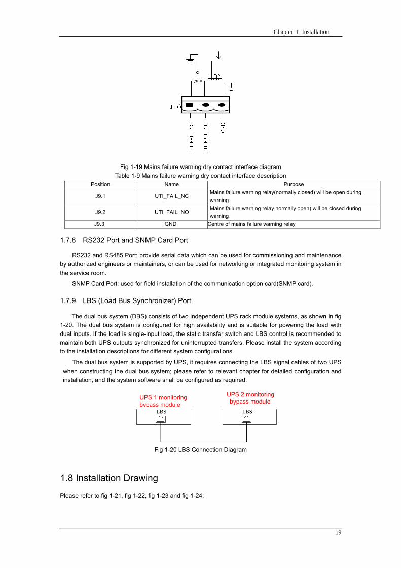
Chapter 1 Installation
19
Fig 1-19 Mains failure warning dry contact interface diagram
Table 1-9 Mains failure warning dry contact interface description Position Name Purpose
J91 UTI_FAIL_NC Mains failure warning relay(normally closed) will be open during
warning
J92 UTI_FAIL_NO Mains failure warning relay normally open) will be closed during
warning
J93 GND Centre of mains failure warning relay
178 RS232 Port and SNMP Card Port
RS232 and RS485 Port provide serial data which can be used for commissioning and maintenance
by authorized engineers or maintainers or can be used for networking or integrated monitoring system in
the service room
SNMP Card Port used for field installation of the communication option card(SNMP card)
179 LBS (Load Bus Synchronizer) Port
The dual bus system (DBS) consists of two independent UPS rack module systems as shown in fig
1-20 The dual bus system is configured for high availability and is suitable for powering the load with
dual inputs If the load is single-input load the static transfer switch and LBS control is recommended to
maintain both UPS outputs synchronized for uninterrupted transfers Please install the system according
to the installation descriptions for different system configurations
The dual bus system is supported by UPS it requires connecting the LBS signal cables of two UPS
when constructing the dual bus system please refer to relevant chapter for detailed configuration and
installation and the system software shall be configured as required
UPS 1
LBS
监控旁路模块 UPS 2
LBS
监控旁路模块
Fig 1-20 LBS Connection Diagram
18 Installation Drawing
Please refer to fig 1-21 fig 1-22 fig 1-23 and fig 1-24
UPS 1 monitoring bypass module
UPS 2 monitoring bypass module
Chapter 1 Installation
20
Fig 1-21 Installation Diagram
Chapter 1 Installation
21
顶视图
2m cabinet front view
16 m cabinet (front view)
Fig 1-22 UPS front view (Unit mm)
Top view
Chapter 1 Installation
22
A
2m cabinet
A
16m cabinet
Fig 1-23 UPS back view
Chapter 1 Installation
23
A
A处放大
Fig 1-24 UPS front view
Amplification of A
24 Chapter 2 Operations
24
Chapter 2 Operations
This chapter introduces the basic knowledge of UPS operations including working principle
operation mode battery management and protection
Warning Hazardous mains voltage andor battery voltage present(s)behind the protective cover
The components that can only be accessed by opening the protective cover with tools cannot be
operated by user
Only qualified service personnel are authorized to remove such covers
21 Introduction
UPS provides the critical load (such as communication and data processing equipment) with high
quality uninterruptible AC power The power from UPS is free from voltage and frequency variations and
disturbances (interruption and spike) experienced at the Mains AC input supply
This is achieved through high frequency double conversion power pulse width modulation (PWM)
associated with full digital signal processing control (DSP) which features high reliability and
convenience for use
211 Principle
As shown in fig 2-1 the AC input mains source is supplied at UPS input and converted into a DC
source This DC source feeds the Inverter that converts the DC source into a clean and input
independent AC source The battery powers the load through the inverter in case of an AC input mains
power failure The utility source can also power the load through the static bypass
When the UPS needs maintenance or repair the load can be transferred to maintenance bypass
without interruption and the power module and bypass module can be removed for maintenance
Chapter 2 Operations 25
25
Fig 2-1 System principle framework
212 Bypass Module
The circuit blocks labeled ldquobypass modulerdquo in fig 2-1 contain electronically controlled switching
circuits that enable the critical load to be connected to either the inverter output or to a bypass power
source via the static bypass line During normal system operation the load is connected to the inverter
but in the event of a UPS overload or inverter failure the load is automatically transferred to the static
bypass line
To provide a clean (no-break) load transfer between the inverter output and static bypass line the
inverter output and bypass supply must be fully synchronized during normal operating conditions This is
achieved through the inverter control electronics which makes the inverter frequency track that of the
static bypass supply provided that the bypass remains within an acceptable frequency window
A manually controlled maintenance bypass supply is incorporated into the UPS design It enables
the critical load to be powered from the utility (bypass) supply while the UPS is shut down for routine
maintenance
Note
When the UPS is operating in bypass mode or on maintenance bypass the connected equipment is
not protected from power failures or surges and sags
22 Operation Mode
The MD UPS is an on-line double-conversion reverse-transfer UPS that permits operation in these
modes
Normal mode
26 Chapter 2 Operations
26
Battery mode
Auto-Restart mode
Bypass mode
Maintenance mode (manual bypass)
ECO mode
Frequency converters mode
221 Normal Mode
The UPS inverter power modules continuously supplies the critical AC load The rectifiercharger
derives power from the AC mains input source and supplies DC power to the inverter while
simultaneously FLOAT or BOOST charging its associated backup battery
222 Battery Mode
Upon failure of the AC mains input power the inverter power modules which obtains power from the
battery supplies the critical AC load There is no interruption in power to the critical load upon failure
After restoration of the AC mains input power the ldquoNormal Moderdquo operation will continue automatically
without the necessity of user intervention
Note UPS can also be started through battery (charged) mode via battery cold start function upon
failure of the AC mains Therefore the battery power can be used independently to improve the
utilization rate of UPS
223 Auto-Restart Mode
The battery may become exhausted following an extended AC mains failure The inverter shuts
down when the battery reaches the End of Discharge voltage (EOD) The UPS may be programmed to
ldquoAuto Recovery after EODrdquo after a delay time if the AC mains recovers This mode and any delay time
are programmed by the commissioning engineer
During the process of delay time the battery will be charged by UPS to prevent any risks to load
equipment from future mains failure
224 Bypass Mode
If the inverter overload capacity is exceeded under normal mode or if the inverter becomes
unavailable for any reason the static transfer switch will perform a transfer of the load from the inverter
to the bypass source with no interruption in power to the critical AC load
225 Maintenance Mode
A manual bypass switch is available to ensure continuity of supply to the critical load when the UPS
becomes unavailable eg during a maintenance procedure
Note This manual bypass switch is fitted in all UPS modules Transfer UPS system to bypass
module for power supply first then close maintenance bypass switch Q2 followed by Q1 and Q3
Warning hazard may occur after transferring to maintenance bypass
After UPS being transferred to maintenance bypass power module and bypass module do not work
no display on LCD and input and output terminals as well as N bus are electrically connected
Chapter 2 Operations 27
27
226 ECO Mode
If economical (ECO) mode is selected the double-conversion UPS will stop to work so as to save
energy During the operation of ECO mode the load power will be supplied by bypass preferentially
When bypass power is within the range of normal frequency and voltage load power will be supplied by
bypass or the system will transfer to inverter input followed by load power interruption which extends
within 34 of the utility period Eg when the frequency is 50Hz the interruption time will be less than
15ms when the frequency is 60Hz the time will be less than 125ms
227 Frequency Converters Mode
If the frequency converter configuration is used by UPS it will provide 50Hz or 60Hz stable output
frequency The range of output frequency is 40Hz~70Hz Under this mode static bypass is unavailable
but battery can be selected according to the actual requirements of battery mode
23 Battery Management
231 Normal Function
The following functions should be fitted by commissioning engineers with specified software
1 Constant current boost charging
Current can be set up
2 Constant voltage boost charging
Voltage of boost charging can be set as required by the type of battery
For Valve Regulated Lead Acid (VRLA) batteries maximum boost charge voltage should not
exceed 24V cell
3 Float charge
Voltage of float charging can be set as required by the type of battery
For VRLA float charge voltage should be between 22V to 23V
4 Float charge temperature compensation (optional)
A coefficient of temperature compensation can be set as required by the type of battery
5 End of discharge (EOD) protection
If the battery voltage is lower than the EOD the battery converter will shut down and the battery is
isolated to avoid further battery discharge EOD is adjustable from 16V to 175V per cell (VRLA) or 09
to 11 V per cell
6 Battery low warning time
It is adjustable between 3 and 60 minutes The default is 5 minutes
232 Advanced Functions (Battery Self-checking and Maintenance)
At periodic intervals 20 of the rated capacity of the battery will be discharged automatically and
the actual load must exceed 20 of the rated UPS (KVA) capacity If the load is less than 20
auto-discharge cannot be executed The periodic interval can be set from 30 to 360 days The battery
self-test can be disabled
ConditionsmdashBattery at float charge for at least 5 hours load equal to 20~100 of rated UPS capacity
TriggermdashManually through the command of ldquoBattery Maintenance Testrdquo in LCD panel or automatically
Battery Self-Test Intervalmdash30-360 days (default setting is battery self-test disabled)
28 Chapter 2 Operations
28
24 Battery Protection
The following functions should be fitted by commissioning engineers with specified software
1 Battery Low Pre-warning
The battery under voltage pre-warning occurs before the end of discharge After this pre-warning
the battery should have the capacity for 3 remaining minutes discharging with full load The time is user
configured from 3 to 60 minutes
2 Battery discharge (EOD)off protection
If the battery voltage is lower than the EOD the battery converter will be shut down EOD is
adjustable from 16V to 175V per cell (VRLA) or 09 to 11 V per cell (NiCd)
3 Battery Circuit Breaker (BCB) Alarm
The alarm occurs when the battery disconnect device disconnects The external battery connects to
the UPS through the external battery circuit breaker The circuit breaker is manually closed and tripped
by the UPS control circuit
Chapter 3 Operation Instructions 29
29
Chapter 3 Operating Steps
This chapter describes UPS operation instructions in detail
All functional keys and LED display involved in operation instructions please refer to chapter 4
During operation the buzzer alarm may occur at any time Select ldquomuterdquo on LED to muffle the audible
alarm
Warning-Hazardous mains voltage andor battery voltage present(s)behind the protective cover
1 The components that can only be accessed by opening the protective cover with tools cannot be
operated by user
2 Only qualified service personnel are authorized to remove such covers
31 Power Switches
As shown in fig 3-1 open the front door of UPS the power switch is visible which includes input
switch output switch and maintenance bypass switch (with anti-misoperation stop plate)
输入开关 输出开关
维修旁路开关
Fig 3-1 Power switch location diagram
32 UPS Start-up
The UPS system only has a maintenance bypass isolating switch and all the other transfers are
processed automatically by internal control logics
Input switch Output switch
Maintenance bypass switch
30 Chapter 3 Operating Instructions
30
321 Normal Module Start
This procedure must be followed when turning on the UPS from a fully powered down condition
The operating procedures are as follows
Warning
This procedure results in mains voltage being applied to the UPS output terminals If any load
equipment is connected to the UPS output terminals please check with the load user that it is safe to
apply power If the load is not ready to receive power then ensure that it is safely to close the output
switch of external distribution cabinet
1 Close UPS output switch and input switch in turns
The LCD starts up at this time The Rectifier indicator flashes during the startup of rectifier The
rectifier enters normal operation state and after about 30s the rectifier indicator goes steady green After
initialization the bypass static switch closes The UPS Mimic LEDs will indicate as shown in table 3-1
Table 3-1 Indicator status
LED Status
Rectifier indicator Green
Battery indicator Red
Bypass indicator Green
Inverter indicator Off
Load indicator Green
Status indicator Green
Note
The output circuit breaker must be closed first followed by input circuit breaker or the rectifier cannot
be started and alarm ldquorectifier failurerdquo
The inverter starts up at this time the inverter indicator flashes After the rectifier enters normal
operation state UPS power supply will transfer from bypass to inverter then the bypass indicator turns
off and load indicator lights The status of indicators is shown in table 3-2
Table 3-2 Indicator Status
LED Status
Rectifier indicator Green
Battery indicator Red
Bypass indicator Off
Inverter indicator Green
Load indicator Green
Status indicator Green
Close external battery switch again battery indicator turns off a few minutes later the battery will be
charged by UPS which will enter normal mode operation The indicator status is shown in table 3-3
Table 3-3 Indicator status
LED Status
Rectifier indicator Green
Battery indicator Green
Bypass indicator Off
Inverter indicator Green
Load indicator Green
Status indicator Green
322 Operating steps of Battery cold Start
1 Check if the batteries have been connected close the external battery switch
Chapter 3 Operation Instructions 31
31
2 Press the red start-up button of battery under the rectifier input circuit breaker for 3 seconds (see fig
3-2)
The LCD starts up at this time The green battery indicator flashes The rectifier enters normal
operation states and after about 30s the battery indicator goes steady green
3 The inverter starts up automatically the green inverter indicator flashes The output of inverter
appears after 60s The UPS works on battery mode
32 Chapter 3 Operating Instructions
32
电池启动按钮
Fig 3-2 Position diagram of battery startup button
Battery startup button
Chapter 3 Operation Instructions 33
33
33 Procedure for Switching between Operation Modes
331 Procedure for Switching the UPS into Battery mode from Normal Mode
Open input switch to cut off the mains UPS enters the battery mode If UPS should be switched to
normal mode wait for a few seconds before close input switch so as to supply the mains again 10s
later the rectifier will start up automatically to supply power to the inverter
332 Procedure for Switching the UPS into Bypass mode from Normal Mode
Select ldquoTran Byprdquo on the LCD or press ldquooffrdquo buttons of each power module in turn
Note
In bypass mode the load is directly fed by the mains power instead of the pure AC power from the
inverter
333 Procedure for Switching the UPS into Normal from Bypass Mode
Select exit bypass mode on the LCD
334 Procedure for Switching the UPS into a Maintenance Bypass from Normal Mode
In normal operation this operation instruction will switch the load from inverter input to maintenance
bypass
Caution
Before making this operation read messages on display to be sure that bypass supply is regular and
the inverter is synchronous with it so as not to have a risk of a short interruption in powering the load
1 Press ldquoTran Byprdquo on the LCD or press ldquooffrdquo on each power module in turns
If press rdquoTran Byprdquo on the LCD the inverter indicator will flash green and the buzzer will alarm
If press ldquooffrdquo on each power module in turns the inverter indicator will go off and the buzzer will
alarm
The load will be transferred to static bypass and the inverter is closed
2 Close maintenance bypass switch Q2 the load power will be supplied by maintenance bypass and
then open the inverter circuit breaker Q1 output switch Q3 and battery switch
Warning
If you need to maintain the module wait for 10 minutes to let the DC bus capacitor fully discharge
before removing corresponding module
335 Procedure for Switching the UPS into Normal from a Maintenance Bypass Mode
This procedure can transfer the load to normal main mode when the UPS is operating under the
maintenance bypass mode
1 Close output switch Q3 and main switch Q1
The bypass indicator goes green and the load power will be supplied by bypass and maintenance
bypass
2 Open maintenance bypass switch Q2
34 Chapter 3 Operating Instructions
34
The load power is supplied by bypass In the meantime the rectifier starts up rectifier indicator goes
green 30s later at this time the inverter will start up automatically and transfer to inverter mode 1 min
later automatically
3 Close external battery switch the battery indicator goes off Check if the battery voltage on LCD
display is normal
34 Procedure for Completely Powering down a UPS
If you need to power down the UPS completely follow the procedures in section 334 to transfer the
UPS from normal mode to maintenance bypass mode
If you need to isolate the UPS from the AC power supply you should open the external input switch
35 EPO Procedure
The EPO button on UPS operator control and display panel is designed to switch off the UPS in
emergency conditions (eg fire flood etc)To achieve this just press the EPO button and the system
will turn off the rectifier inverter and stop powering the load immediately (including the inverter and
bypass output) and the battery stops charging or discharging
If the input utility is present the UPS control circuit will remain active however the output will be
turned off To completely isolate the UPS you need to open the external mains input supply to the UPS
rack
36 Language Selection
The LCD is available in two languages Chinese English and Korean
The language can be selected through LCD prompt window
37 Control Password
When the LCD displays ldquoinput control password 1rdquo the initial password is 12345678
Chapter 4 Operator Control and Display Panel 35
35
Chapter 4 Operator Control and Display Panel
This chapter introduces the functions and operation instructions of the parts on UPS operator control
and display panel in detail and provides LCD display information including LCD display types detailed
menu information prompt window information and UPS alarm list
41 Introduction
The operator control and display panel is located on the front panel of the UPS Through this LCD
panel the operator can operate and control the UPS and check all measured parameters UPS and
battery status and event and alarm logs The operator control panel is divided into three functional areas
as shown in fig 4-1 mimic current path LCD display amp Menu keys and Control and Operation Keys The
detailed description of parts on operator control and display panel is shown in table 4-1
Fig 4-1 UPS operator control and display panel
Table 4-1 Description of UPS operator control and display panel
Part No Function Button Function
REC Rectifier indicator EPO EPO switch
BAT Battery indicator TAB switch
BYP Bypass indicator ENTER confirm
INV Inverter indicator ESC exit
OUTPUT Load indicator
STATUS Status indicator
36 Chapter 4 Operator Control and Display Panel
36
411 LED Indicator
The LEDs shown on the mini current path represent the various UPS power paths and show the
current UPS operating status The status description of indicators is shown in table 4-2
Table 4-2 Status description of indicator
Indicator State Purpose
Rectifier
indicator
Steady green Rectifier normal for all modules
Flashing green Rectifier for at least on module normal mains normal
Steady red Rectifier fault
Flashing red Mains abnormal for at least one module
Off Rectifier not operating
Battery
indicator
Steady green Battery charging
Flashing green Battery discharging
Steady red
Battery abnormal (battery failure no battery or battery reverse) or
battery converter abnormal (failure over current or over temperature)
EOD
Flashing red Battery low voltage
Off Battery and battery converter normal battery not charging
Bypass
indicator
Steady green Load power supplied by bypass
Steady red Bypass power abnormal or out of normal range or static bypass
switch fault
Flashing red Bypass voltage abnormal
Off Bypass normal
Inverter
indicator
Steady green Load power supplied by inverter
Flashing green Inverter On start synchronization of standby (ECO mode) for at least
one module
Steady red System power not supplied by inverter inverter fault for at least one
module
Flashing red System power supplied by inverter inverter fault for at least one
module
Off Inverter not operating for all modules
Load
indicator
Steady green UPS output ON and normal
Steady red UPS output overload and overtime or output short or output no power
supply
Flashing red Overload output of UPS
Off No output of UPS
Status
indicator
Steady green Normal operation
Steady red Failure
412 Audible Alarm (buzzer)
There are two different types of audible alarm during UPS operation as shown in table 4-3
Table 4-3 description of audible alarm
Alarm Purpose
Two short alarm with
a long one
when system has general alarm (for example AC fault) this audible alarm
can be heard
Continuous alarm When system has serious faults (for example fuse or hardware fault) this
audible alarm can be heard
Chapter 4 Operator Control and Display Panel 37
37
413 Functional Keys
There are 4 functional keys on operator control and display panel which are used together with LCD
The functions description is shown in table 4-4
Table 4-4 Functions of functional keys
Functional key Functions
EPO switch To cut off the load power to shut down the rectifier inverter static
bypass and battery
TAB switch
ENTER confirm
ESC exit
42 LCD Display Type
Following the self-check of UPS LCD display the main LCD display is shown as fig 4-2 which can
be divided into three display windows system information data command and current record
Fig 4-2 Main LCD display
The description of LCD icon is shown in table 4-5
Table 4-5 Description of LCD icons
Icon Description
Bypass parameter
UPS system
information
window
Data
command
window
Current
record
window
38 Chapter 4 Operator Control and Display Panel
38
Icon Description
Main input parameter
History file system information
Function setting (display calibration password setting time setting date format
communication protocol and language setting) system setting (used by product
maintainers)
Battery data battery parameter setting (used by service staff)
Test (battery self-test battery maintenance)
Functional keys used by service staff (fault clearing history file clearing noise
clearing manual switch of bypass) userrsquos setting (system mode machine
number system ID output voltage adjustment frequency tracing speed
frequency tracing limit)
Output parameter
Load
Noise clearing noise clearing cancel
Log view page updown
Select a icon on LCD as shown in fig 4-3 to view the UPS parameter represented by this icon eg
select the LCD will display the data of system main input
Chapter 4 Operator Control and Display Panel 39
39
Fig 4-3 Select data
Or select and confirm a module as shown in fig 4-4 the LCD will display the
operating status of this module
Fig 4-4 Select a module
40 Chapter 4 Operator Control and Display Panel
40
Select in the operating status of a module to view the main input data of this module
Select in the operating status of a module to view the main output data of this module
Select in the operating status of a module to view the load data of this module
Select in the operating status of a module to view the maintenance code and module
software code of this module
Select to return to the previous page
Select to return to the home page
Default display
During the operation of system if therersquos no alarm in 2 min the system will display default After a
short delay the backlight of LCD display goes off press any key to reactivate the display
43 Detailed Description of Menu Items
The LCD main display shown in fig 4-2 is described in details below
UPS information window
UPS information window display the current time and UPS name The information of the window is
not necessary for the user to operate The information of this window is given in table 4-6
Table 4-6 Description of items in UPS system information window
Display contents Meaning
MD12020 UPS Name
1200 Current Time (format 24 hours hours minute)
UPS menu and data window
UPS menu window displays the menu name of data window while the data window displays the
related contents of selected menu in menu window Select UPS menu and data window to browse
related parameters of UPS and set related functions The details are given in table 4-7
Table 4-7 Item description of UPS menu and data window
Menu name Menu item Meaning
Main input
V phase(V) V phase
I phase(A) I phase
Freq(Hz) Input frequency
PF Power factor
Bypass input
V phase(V) V phase
Freq (Hz) Bypass frequency
I phase(A) I phase
PF Power factor
AC output
V phase(V) V phase
I phase(A) I phase
Freq (Hz) Output frequency
PF Power factor
This UPS Sout (kVA) Sout Apparent Power
Chapter 4 Operator Control and Display Panel 41
41
Menu name Menu item Meaning
modulersquos
load
Pout (kW) Pout Active Power
Qout (kVAR) Qout Reactive Power
Load () Load (The percentage of the UPS rating load)
Battery data
Environmental
Temp Environmental Temp
Battery
voltage(V) Battery bus voltage
Battery current
A) Battery bus current
Battery
Temp() Battery Temp
Remaining Time
(Min) Remaining battery backup time
Battery capacity
() The percentage compared with new battery capacity
battery
equalized
charging
Battery is equalized charging
battery float
charging Battery is float charging
Battery
disconnected Battery is not connected
Current
record (current alarm)
Display all current alarm The alarm list displayed on LCD of
UPS operator control and display panel please refer to table 4-9
History
record (history alarm)
Display all history alarm The alarm list displayed on LCD of
UPS operator control and display panel please refer to table 4-9
Menu
Language
(language
option) 2 languages can be selected
Settings
Display
calibration Adjust the accuracy of LCD display
Date format set MM DD YYYY and YYYY MM DD formats can be selected
Date amp Time DateTime set
Language set User can set the language (Chinese and English)
Communication
mode
Set communication mode MODBUS Power protocol and
company custom protocol modes can be selected Power
protocol mode can be divided into equipment address baud
rate set MODBUS protocol mode can be divided into
communication mode (RTUASCⅡ) equipment address
baud rate and check-bit set Company custom protocol mode
is the customed protocol of the company no option is
available
Control
password set User can modify control password 1
Test
Command
(Battery Test
Control
Battery
maintenance
test
This test will lead to the battery being partly discharged to
activate battery at the same time the approximate battery
capacity will be obtained Bypass must be in normal condition
the battery capacity should be above 25
42 Chapter 4 Operator Control and Display Panel
42
Menu name Menu item Meaning
Battery
self-check test
UPS switches to battery discharge for discharging to test if the
battery is normal Bypass must be in normal condition the
battery capacity should be above 25
Stop testing Manually Stop the test including maintenance test capacity test
UPS system
information
Monitoring
software version Provide monitoring software version
Rectified
software version Provide rectified software version
Inverted
software version Provide inverted software version
Serial No The serial no set when delivery from the factory
Rated
information Network setting of system operating
Module type Type of the module
44 Alarm List
The follow table 4-8 gives the complete list of all the UPS events displayed by history record window
and current record window
Table 4-8 Alarm List
Alarm Explanation
UPS power supply The system is in normal inverted power supply status
Bypass power
supply The system is in bypass power supply status
No power supply System no output
Battery equalized
charging Battery is in boost charging
Battery float
charging Battery is in float charging
Battery discharging The system is operating in battery discharging status
Battery connected Battery is connected
Battery
disconnected Battery is not connected
Maintenance circuit
breaker close Maintenance circuit breaker is close
Maintenance circuit
breaker open Maintenance circuit breaker is open
Emergency
shutdown System emergency shutdownEPO
Generator
connected External generator is connected
Mains abnormal Input mains abnormal
Bypass phase
conversion Bypass input phase converse
Bypass voltage
abnormal Bypass input voltage abnormal
Bypass fault Bypass fault
Bypass overload Bypass output is overload
Up to bypass
overtime of Bypass is overtime of overload
Chapter 4 Operator Control and Display Panel 43
43
Alarm Explanation
overload
Bypass frequency
tracing exceeds Bypass frequency is out of the tracing range
Switch times up to
in this hour
The times of switch between bypass and inverter exceeds 5 times in the latest
hour
Output short System output short
Battery EOD Battery voltage achieves shutdown point
Battery self-check The system enters battery self-check mode
Battery self-check
success Battery normal during system self-check
Battery manual
check failure Battery fault during system self-check
Battery
maintenance The system is in battery maintenance status
Battery
maintenance
success
Battery maintenance status completes
Battery
maintenance failure Battery maintenance process is not normal
Stop testing Battery self-check or battery maintenance status stops
Fault clearing Clear the alarmed fault
Delete history
record Delete all history record
N communication
node connected N module is connected to UPS system
N communication
node disconnected N module is not connected to UPS system
N rectifier fault N module rectifier fault
N inverter fault N module inverter fault
N rectifier
overheat N module rectifier overheat
N fan fault N module fan fault
N output overload N module output overload
N overtime of
overload N module output overtime of overload
N inverter
overheat N module inverter overheat
Inverter power
supply ban Inverter power ban supply
Manual switch of
bypass Switch the system to bypass output manually
Cancel manual
switch of bypass Switch the system from bypass to inverter output manually
Battery low voltage Battery low voltage
Battery reversal Battery polarity reversal
N inverter
protection N module inverter protection
Input N line
disconnected System input N line is not connected
Bypass fan fault Bypass module fan fault
N manual N module manual power off
44 Chapter 4 Operator Control and Display Panel
44
Alarm Explanation
shutdown
Chapter 5 Maintenance 45
45
Chapter 5 Installation of Parallel Operation System
The parallel operation system is installed as required by the installation procedures of the single
system and this chapter
The single devices are put parallel and connected as shown in fig 5-1 and the difference between
the lengths of the output cables of the single devices is not more than 10m It is recommended to use an
external bypass cabinet to facilitate maintenance and system testing
Fig 5-1 Typical 1+N parallel operation system
Note when the load exceeds is the capacity of the single device the maintenance bypass
switch CB3 must be removed
The cables for the parallel operation provide double insulation shielding up to 30m long the control
cables for the parallel operation must be connected with all single devices to form a closed loop as
shown in fig5-2
Other power supplies
Rectifier
Charger Inverter Inverter
Output power supply
Load connected
Mains power input L1 L2 L3 N terminal
Mains power inputL1 L2 L3 N terminal
Rectifier
Charger
46 Chapter 5 Maintenance
46
Fig5-2 parallel cables
Chapter 5 Maintenance 47
47
Chapter 6 Maintenance
This chapter introduces UPS maintenance including the maintenance instructions of power module
monitoring bypass module and the change method of dust filter
61 Instruction to Power Bypass and Output Power Distribution
Module
611 Precautions
1 Only maintaining engineers can maintain the power module and monitoring bypass module
2 In principle the power module and bypass module should be disassembled from top to bottom so
as to prevent any inclination from high gravity centre of the cabinet
3 To ensure the safety before maintaining power module and bypass module be sure to use a
multimeter to measure the DC bus capacitor voltage and ensure the voltage is below 60V before
operation and use a multimeter to measure the voltage between operating parts and the earth to
ensure the voltage is lower than hazardous voltage ie DC voltage is lower than 60Vdc and AC
maximum Voltage is lower than 424Vac
4 Bypass module doesnrsquot support any hot insertion and extraction only when UPS is in maintenance
bypass mode or UPS is completely power off can the bypass module be disassembled
5 The module can be maintained 10 mins after extracting power module and bypass module which
can be inserted into the cabinet 10 mins later
612 Instruction to Power Module
Suppose UPS were in normal mode and bypass were normal a module shall be maintained at
first
1 Press OFF of the module with a pin point or other tiny matter the module will shut down
automatically and exit the system
Note ensure if the remaining module will be overload when exiting a module If therersquos any risk of
overload transfer the whole UPS system to bypass followed by other operations
2 Take off the fixing bolt on the two sides of front and back plate of power module 10 mins later
extract the module from the cabinet
3 After maintaining the module push the module into the equipment cabinet (the interval between
two modules shall be more than 10s) fix the screw on the two sides Then the module will be
connected to UPS system automatically
613 Instruction to Bypass Module
Suppose UPS were in normal mode and the bypass were normal
1 Select LCD touch screen manual switch of bypass the UPS power will be supplied by bypass
2 Close maintenance bypass switch the UPS power will be supplied by maintenance bypass
3 Open UPS output switch and input switch
4 Open external battery switch
48 Chapter 5 Maintenance
48
5 Take off the fixing bolt at the two sides of front board of bypass module extract the front cable
assembly of the module and extract the module from the cabinet
6 After maintaining the module insert the module into the cabinet tighten the screw at the two sides
and connect the front cable assembly of manufacturerrsquos module
7 Close UPS output switch and input switch in turn
2 mins later bypass indicator on the operator control and display panel lights on which indicates
the normal power supply of bypass
8 Open maintenance bypass switch the inverter starts automatically 60s later the UPS will transfer
to normal mode
62 Replacing Dust Screen (optional)
As shown in fig 5-1 there are 3~4 dust filters on the back of UPSrsquo front door each screen is held in
place by a bracket on either side of each filter The procedure of replacing each filter is as follows
1 Open the UPSrsquo front door and locate the filters on the back side of the front door
2 Remove one bracket
3 Remove the dust screen to be replaced and insert the clean one
4 Reinstall the bracket
防尘网固定条
Fig 5-1 Dust screen on the back side of UPS front door
Bracket
Dust screen
Appendix 2 Toxic or Hazardous Materials or Elements Identification Table 49
49
Chapter 7 Product Specification
This chapter provides UPS product specification
71 Applicable Standards
The UPS has been designed to conform to the following European and international standards
Table 6-1 Compliance with European and International Standards
Item Normative reference
General safety requirements for UPS
used in operator access areas EN50091-1-1IEC62040-1-1AS 62040-1-1
Electromagnetic compatibility (EMC)
requirements for UPS EN50091-2IEC62040-2AS 62040-2(C3)
Method of specifying the performance
and test requirements of UPS EN50091-3IEC62040-3AS 62040-3(VFI SS 111)
Note The above mentioned product standards incorporate relevant compliance clauses with generic
IEC and EN standards for safety (IECENAS60950) electromagnetic emission and immunity
(IECEN AS61000 series) and construction (IECENAS60146 series and 60950)
72 Environmental Characteristics
Table 6-2 Environmental Properties
Items Unit Requirements
Acoustic noise level at 1
meter dB 550
Altitude of Operation m le1000m above sea level derate power by 1 per 100m
between 1000m and 2000m
Relative Humidity RH 0 to 95 non condensing
Operating Temperature 0 to 40 deg Battery life is halved for every 10degC increase
above 20degC
UPS Storage-Transport
Temperature -20~70
Recommended Battery
Storage Temperature -20~30 (20degC for optimum battery storage)
73 Mechanical Characteristics
Table 6-3 Mechanical Properties
Cabinet Specification Unit MD6010 MD9015
MD12020
MD10010 MD15015
MD20020
Mechanical Dimension
WtimesDtimesH mm 600times900times1600 600times900times2000
Weight kg 151 182
Color NA Black
Protection Level
IEC(60529) NA IP20
50 Chapter 5 Maintenance
50
Module type Unit MU10 MU15 MU20
Mechanical Dimension
WtimesDtimesH mm 440times590times134
Weight kg 21 22 22
Color NA Black
74 Electrical Characteristics (Input Rectifier)
Table 6-4 Rectifier AC input (mains)
Items Unit Parameter
Rated AC Input
Voltage Vac
380400415(three-phase and sharing neutral with the
bypass input)
Input voltage range Vac -40~+25
Frequency2 Hz 5060(range 40Hz~70Hz)
Power factor kWkVA full load 099
THD THDI 3
75 Electrical Characteristics (Intermediate DC Link)
Table 6-5 Battery
Items Unit Parameters
Battery bus
voltage Vdc Nominal plusmn240V one-side range 198V~288V
Quantity of
lead-acid cells Nominal 40=[1 battery(12V) ] 240=[1 battery(2V) ]
Float charge
voltage Vcell(VRLA)
225Vcell(selectable from 22Vcell~235Vcell)
Constant current and constant voltage charge mode
Temperature
compensation mVcl -30(selectable from 0~-50 25 or 30 or inhibit)
Ripple voltage V float le1
Ripple current C10 le5
equalized
charge voltage VRLA
24Vcell(selectable from 230Vcell~245Vcell)
Constant current and constant voltage charge mode
final
discharging
voltage
Vcell(VRLA)
165Vcell(selectable from 160Vcell ~ 1750Vcell) 06C
discharge current
175Vcell (selectable from 165Vcell ~ 18Vcell) 015C
discharge current
(EOD voltage changes linearly within the set range according to
discharge current)
Battery Charge Vcell 24Vcell(selectable from 23Vcell~245Vcell)
Constant current and constant voltage charge mode
Battery
Charging Power
Max Current
kW 10 UPS capacity (selectable from 0~20 UPS capacity)
Appendix 2 Toxic or Hazardous Materials or Elements Identification Table 51
51
76 Electrical Characteristics (Inverter Output)
Table 6-6 Inverter Output (to important load)
Rated
capacity(kVA) Unit 10~200
Rated AC voltage1 Vac 380400415(three-phase four-wire and sharing neutral with the
bypass)
Freqency2 Hz 5060
overload
110 load 1 hour
125 load 10min
150 load 1min
>150 load 200ms
Fault current 340 short current limitation for 200ms
Non linear load
capability 3 100
Neutral current
capability 170
Steady state
voltage stability
plusmn1(balanced load)
plusmn15(100 imbalance load)
Transient voltage
response 4 plusmn5
THD <15(linear load) <5(non linear load3)
Synchronization -
Window Rated frequency plusmn2Hz(selectable plusmn1~plusmn5Hz)
Max change rate of
synch frequency Hzs 1 selectable 01~5
Inverter voltage
range V(ac) plusmn5
Note
1 Factory setting is 380V Commissioning engineers can set to 400V or 415V
2 Factory setting is 50Hz Commissioning engineers can set to 60Hz
3 EN50091-3(1458) peak value factor is 3 1
4 IEC62040-3EN50091-3 including 0~100~0 load transient the recovery time is half
circle to within 5 of stable output voltage
52 Chapter 5 Maintenance
52
77 Electrical Characteristics(Bypass Mains Input)
Table 6-7 Bypass Mains Input
Rated
capacity(kVA) Unit 60 90 100 120 150 200
Rated AC
Voltage1 Vac
380400415
three-phase four-wire sharing neutral with the rectifier input and providing neutral
reference for the output
Rated current A
91380V
87400V
83415V
136380V
130400V
124415V
151380V
144400V
138415V
182380V
174400V
166415V
227380V
216400V
207415V
302380V
288400V
276415V
Overload
125 load long term
130 load 1 hour
150 load 6min
1000 load 100ms
Superior
protection
bypass line
NA Thermal-magnetic breaker the capacity is 125 of rated current output
IEC60947-2 curve C
Current rating
of neutral cable A 17timesIn
Frequency2 Hz 5060
Switch time
(between
bypass and
inverter)
ms Synchronized switch le1ms
Bypass voltage
tolerance Vac
Upper limit +10+15or+20 default +20
Lower limit -10 -20 -30 or-40 default-20
(acceptable stable bypass voltage delay 10s)
Bypass
frequency
tolerance
plusmn25 plusmn5 plusmn10 or plusmn20 default plusmn10
Synchronizatio
n-Window Hz Rated frequencyplusmn2Hz (selectable from plusmn05Hz~plusmn5Hz)
Note
1 Factory setting is 400V Commissioning engineers can set to 380V or 415V
2 Factory setting is 50Hz Commissioning engineers can set to 60Hz For example UPS is set to frequency
inverter mode and then bypass status will be neglected
78 Efficiency
Table 6-8 Efficiency Loss and Air Exchange
Rated Efficiency (kVA) Unit 10~200kVA
Normal mode(dual conversion) 95
ECO mode 99
Battery discharging efficiency (DCAC) (battery at nominal voltage 480Vdc and full-rated linear load)
battery mode 95
Appendix 2 Toxic or Hazardous Materials or Elements Identification Table 53
53
Appendix A A Guidebook to Ordering and Selection of MU System
MD series UPS module can be divided into equipment cabinet and power module For the cabinet
lectotype please refer to the description in fig 6-1
Fig 6-1 Cabinet Selection
For single power module type please refers to the description in fig 6-2
Fig 6-2 Power Module Selection
Egg the requirements of a plant room are given below
The maximum power supply of the plant room is 120kVA however it is expected to be expanded to
200kVA in 3-5 years Therefore a 200kVA cabinet and 6 20kVA power module can be purchased to
constitute an uninterrupted 120kVA power system which can be expanded to 200kVA on-line The order
symbol is
1 set MD20020
6 set MU20
Option list
MD-SNMP card remote network monitoring card
MD-1600 dust filter dust screen for 16m cabinet
MD-2000 dust filter dust screen for 2m cabinet
Represents the capacity of a single power module
10 represents 10kVA
15 represents 15kVA
20 represents 20kVA
represents a single power module
Represents UPS system capacitypower module
06010 represents 60kVA10kVA
09015 represents 90kVA15kVA
12020 represents 120kVA20kVA
15015 represents 150kVA15kVA
20020 represents 200kVA20kVA
MD represents UPS cabinet
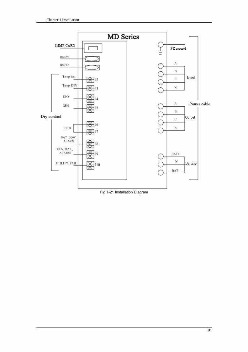
Chapter 1 Installation
20
Fig 1-21 Installation Diagram
Chapter 1 Installation
21
顶视图
2m cabinet front view
16 m cabinet (front view)
Fig 1-22 UPS front view (Unit mm)
Top view
Chapter 1 Installation
22
A
2m cabinet
A
16m cabinet
Fig 1-23 UPS back view
Chapter 1 Installation
23
A
A处放大
Fig 1-24 UPS front view
Amplification of A
24 Chapter 2 Operations
24
Chapter 2 Operations
This chapter introduces the basic knowledge of UPS operations including working principle
operation mode battery management and protection
Warning Hazardous mains voltage andor battery voltage present(s)behind the protective cover
The components that can only be accessed by opening the protective cover with tools cannot be
operated by user
Only qualified service personnel are authorized to remove such covers
21 Introduction
UPS provides the critical load (such as communication and data processing equipment) with high
quality uninterruptible AC power The power from UPS is free from voltage and frequency variations and
disturbances (interruption and spike) experienced at the Mains AC input supply
This is achieved through high frequency double conversion power pulse width modulation (PWM)
associated with full digital signal processing control (DSP) which features high reliability and
convenience for use
211 Principle
As shown in fig 2-1 the AC input mains source is supplied at UPS input and converted into a DC
source This DC source feeds the Inverter that converts the DC source into a clean and input
independent AC source The battery powers the load through the inverter in case of an AC input mains
power failure The utility source can also power the load through the static bypass
When the UPS needs maintenance or repair the load can be transferred to maintenance bypass
without interruption and the power module and bypass module can be removed for maintenance
Chapter 2 Operations 25
25
Fig 2-1 System principle framework
212 Bypass Module
The circuit blocks labeled ldquobypass modulerdquo in fig 2-1 contain electronically controlled switching
circuits that enable the critical load to be connected to either the inverter output or to a bypass power
source via the static bypass line During normal system operation the load is connected to the inverter
but in the event of a UPS overload or inverter failure the load is automatically transferred to the static
bypass line
To provide a clean (no-break) load transfer between the inverter output and static bypass line the
inverter output and bypass supply must be fully synchronized during normal operating conditions This is
achieved through the inverter control electronics which makes the inverter frequency track that of the
static bypass supply provided that the bypass remains within an acceptable frequency window
A manually controlled maintenance bypass supply is incorporated into the UPS design It enables
the critical load to be powered from the utility (bypass) supply while the UPS is shut down for routine
maintenance
Note
When the UPS is operating in bypass mode or on maintenance bypass the connected equipment is
not protected from power failures or surges and sags
22 Operation Mode
The MD UPS is an on-line double-conversion reverse-transfer UPS that permits operation in these
modes
Normal mode
26 Chapter 2 Operations
26
Battery mode
Auto-Restart mode
Bypass mode
Maintenance mode (manual bypass)
ECO mode
Frequency converters mode
221 Normal Mode
The UPS inverter power modules continuously supplies the critical AC load The rectifiercharger
derives power from the AC mains input source and supplies DC power to the inverter while
simultaneously FLOAT or BOOST charging its associated backup battery
222 Battery Mode
Upon failure of the AC mains input power the inverter power modules which obtains power from the
battery supplies the critical AC load There is no interruption in power to the critical load upon failure
After restoration of the AC mains input power the ldquoNormal Moderdquo operation will continue automatically
without the necessity of user intervention
Note UPS can also be started through battery (charged) mode via battery cold start function upon
failure of the AC mains Therefore the battery power can be used independently to improve the
utilization rate of UPS
223 Auto-Restart Mode
The battery may become exhausted following an extended AC mains failure The inverter shuts
down when the battery reaches the End of Discharge voltage (EOD) The UPS may be programmed to
ldquoAuto Recovery after EODrdquo after a delay time if the AC mains recovers This mode and any delay time
are programmed by the commissioning engineer
During the process of delay time the battery will be charged by UPS to prevent any risks to load
equipment from future mains failure
224 Bypass Mode
If the inverter overload capacity is exceeded under normal mode or if the inverter becomes
unavailable for any reason the static transfer switch will perform a transfer of the load from the inverter
to the bypass source with no interruption in power to the critical AC load
225 Maintenance Mode
A manual bypass switch is available to ensure continuity of supply to the critical load when the UPS
becomes unavailable eg during a maintenance procedure
Note This manual bypass switch is fitted in all UPS modules Transfer UPS system to bypass
module for power supply first then close maintenance bypass switch Q2 followed by Q1 and Q3
Warning hazard may occur after transferring to maintenance bypass
After UPS being transferred to maintenance bypass power module and bypass module do not work
no display on LCD and input and output terminals as well as N bus are electrically connected
Chapter 2 Operations 27
27
226 ECO Mode
If economical (ECO) mode is selected the double-conversion UPS will stop to work so as to save
energy During the operation of ECO mode the load power will be supplied by bypass preferentially
When bypass power is within the range of normal frequency and voltage load power will be supplied by
bypass or the system will transfer to inverter input followed by load power interruption which extends
within 34 of the utility period Eg when the frequency is 50Hz the interruption time will be less than
15ms when the frequency is 60Hz the time will be less than 125ms
227 Frequency Converters Mode
If the frequency converter configuration is used by UPS it will provide 50Hz or 60Hz stable output
frequency The range of output frequency is 40Hz~70Hz Under this mode static bypass is unavailable
but battery can be selected according to the actual requirements of battery mode
23 Battery Management
231 Normal Function
The following functions should be fitted by commissioning engineers with specified software
1 Constant current boost charging
Current can be set up
2 Constant voltage boost charging
Voltage of boost charging can be set as required by the type of battery
For Valve Regulated Lead Acid (VRLA) batteries maximum boost charge voltage should not
exceed 24V cell
3 Float charge
Voltage of float charging can be set as required by the type of battery
For VRLA float charge voltage should be between 22V to 23V
4 Float charge temperature compensation (optional)
A coefficient of temperature compensation can be set as required by the type of battery
5 End of discharge (EOD) protection
If the battery voltage is lower than the EOD the battery converter will shut down and the battery is
isolated to avoid further battery discharge EOD is adjustable from 16V to 175V per cell (VRLA) or 09
to 11 V per cell
6 Battery low warning time
It is adjustable between 3 and 60 minutes The default is 5 minutes
232 Advanced Functions (Battery Self-checking and Maintenance)
At periodic intervals 20 of the rated capacity of the battery will be discharged automatically and
the actual load must exceed 20 of the rated UPS (KVA) capacity If the load is less than 20
auto-discharge cannot be executed The periodic interval can be set from 30 to 360 days The battery
self-test can be disabled
ConditionsmdashBattery at float charge for at least 5 hours load equal to 20~100 of rated UPS capacity
TriggermdashManually through the command of ldquoBattery Maintenance Testrdquo in LCD panel or automatically
Battery Self-Test Intervalmdash30-360 days (default setting is battery self-test disabled)
28 Chapter 2 Operations
28
24 Battery Protection
The following functions should be fitted by commissioning engineers with specified software
1 Battery Low Pre-warning
The battery under voltage pre-warning occurs before the end of discharge After this pre-warning
the battery should have the capacity for 3 remaining minutes discharging with full load The time is user
configured from 3 to 60 minutes
2 Battery discharge (EOD)off protection
If the battery voltage is lower than the EOD the battery converter will be shut down EOD is
adjustable from 16V to 175V per cell (VRLA) or 09 to 11 V per cell (NiCd)
3 Battery Circuit Breaker (BCB) Alarm
The alarm occurs when the battery disconnect device disconnects The external battery connects to
the UPS through the external battery circuit breaker The circuit breaker is manually closed and tripped
by the UPS control circuit
Chapter 3 Operation Instructions 29
29
Chapter 3 Operating Steps
This chapter describes UPS operation instructions in detail
All functional keys and LED display involved in operation instructions please refer to chapter 4
During operation the buzzer alarm may occur at any time Select ldquomuterdquo on LED to muffle the audible
alarm
Warning-Hazardous mains voltage andor battery voltage present(s)behind the protective cover
1 The components that can only be accessed by opening the protective cover with tools cannot be
operated by user
2 Only qualified service personnel are authorized to remove such covers
31 Power Switches
As shown in fig 3-1 open the front door of UPS the power switch is visible which includes input
switch output switch and maintenance bypass switch (with anti-misoperation stop plate)
输入开关 输出开关
维修旁路开关
Fig 3-1 Power switch location diagram
32 UPS Start-up
The UPS system only has a maintenance bypass isolating switch and all the other transfers are
processed automatically by internal control logics
Input switch Output switch
Maintenance bypass switch
30 Chapter 3 Operating Instructions
30
321 Normal Module Start
This procedure must be followed when turning on the UPS from a fully powered down condition
The operating procedures are as follows
Warning
This procedure results in mains voltage being applied to the UPS output terminals If any load
equipment is connected to the UPS output terminals please check with the load user that it is safe to
apply power If the load is not ready to receive power then ensure that it is safely to close the output
switch of external distribution cabinet
1 Close UPS output switch and input switch in turns
The LCD starts up at this time The Rectifier indicator flashes during the startup of rectifier The
rectifier enters normal operation state and after about 30s the rectifier indicator goes steady green After
initialization the bypass static switch closes The UPS Mimic LEDs will indicate as shown in table 3-1
Table 3-1 Indicator status
LED Status
Rectifier indicator Green
Battery indicator Red
Bypass indicator Green
Inverter indicator Off
Load indicator Green
Status indicator Green
Note
The output circuit breaker must be closed first followed by input circuit breaker or the rectifier cannot
be started and alarm ldquorectifier failurerdquo
The inverter starts up at this time the inverter indicator flashes After the rectifier enters normal
operation state UPS power supply will transfer from bypass to inverter then the bypass indicator turns
off and load indicator lights The status of indicators is shown in table 3-2
Table 3-2 Indicator Status
LED Status
Rectifier indicator Green
Battery indicator Red
Bypass indicator Off
Inverter indicator Green
Load indicator Green
Status indicator Green
Close external battery switch again battery indicator turns off a few minutes later the battery will be
charged by UPS which will enter normal mode operation The indicator status is shown in table 3-3
Table 3-3 Indicator status
LED Status
Rectifier indicator Green
Battery indicator Green
Bypass indicator Off
Inverter indicator Green
Load indicator Green
Status indicator Green
322 Operating steps of Battery cold Start
1 Check if the batteries have been connected close the external battery switch
Chapter 3 Operation Instructions 31
31
2 Press the red start-up button of battery under the rectifier input circuit breaker for 3 seconds (see fig
3-2)
The LCD starts up at this time The green battery indicator flashes The rectifier enters normal
operation states and after about 30s the battery indicator goes steady green
3 The inverter starts up automatically the green inverter indicator flashes The output of inverter
appears after 60s The UPS works on battery mode
32 Chapter 3 Operating Instructions
32
电池启动按钮
Fig 3-2 Position diagram of battery startup button
Battery startup button
Chapter 3 Operation Instructions 33
33
33 Procedure for Switching between Operation Modes
331 Procedure for Switching the UPS into Battery mode from Normal Mode
Open input switch to cut off the mains UPS enters the battery mode If UPS should be switched to
normal mode wait for a few seconds before close input switch so as to supply the mains again 10s
later the rectifier will start up automatically to supply power to the inverter
332 Procedure for Switching the UPS into Bypass mode from Normal Mode
Select ldquoTran Byprdquo on the LCD or press ldquooffrdquo buttons of each power module in turn
Note
In bypass mode the load is directly fed by the mains power instead of the pure AC power from the
inverter
333 Procedure for Switching the UPS into Normal from Bypass Mode
Select exit bypass mode on the LCD
334 Procedure for Switching the UPS into a Maintenance Bypass from Normal Mode
In normal operation this operation instruction will switch the load from inverter input to maintenance
bypass
Caution
Before making this operation read messages on display to be sure that bypass supply is regular and
the inverter is synchronous with it so as not to have a risk of a short interruption in powering the load
1 Press ldquoTran Byprdquo on the LCD or press ldquooffrdquo on each power module in turns
If press rdquoTran Byprdquo on the LCD the inverter indicator will flash green and the buzzer will alarm
If press ldquooffrdquo on each power module in turns the inverter indicator will go off and the buzzer will
alarm
The load will be transferred to static bypass and the inverter is closed
2 Close maintenance bypass switch Q2 the load power will be supplied by maintenance bypass and
then open the inverter circuit breaker Q1 output switch Q3 and battery switch
Warning
If you need to maintain the module wait for 10 minutes to let the DC bus capacitor fully discharge
before removing corresponding module
335 Procedure for Switching the UPS into Normal from a Maintenance Bypass Mode
This procedure can transfer the load to normal main mode when the UPS is operating under the
maintenance bypass mode
1 Close output switch Q3 and main switch Q1
The bypass indicator goes green and the load power will be supplied by bypass and maintenance
bypass
2 Open maintenance bypass switch Q2
34 Chapter 3 Operating Instructions
34
The load power is supplied by bypass In the meantime the rectifier starts up rectifier indicator goes
green 30s later at this time the inverter will start up automatically and transfer to inverter mode 1 min
later automatically
3 Close external battery switch the battery indicator goes off Check if the battery voltage on LCD
display is normal
34 Procedure for Completely Powering down a UPS
If you need to power down the UPS completely follow the procedures in section 334 to transfer the
UPS from normal mode to maintenance bypass mode
If you need to isolate the UPS from the AC power supply you should open the external input switch
35 EPO Procedure
The EPO button on UPS operator control and display panel is designed to switch off the UPS in
emergency conditions (eg fire flood etc)To achieve this just press the EPO button and the system
will turn off the rectifier inverter and stop powering the load immediately (including the inverter and
bypass output) and the battery stops charging or discharging
If the input utility is present the UPS control circuit will remain active however the output will be
turned off To completely isolate the UPS you need to open the external mains input supply to the UPS
rack
36 Language Selection
The LCD is available in two languages Chinese English and Korean
The language can be selected through LCD prompt window
37 Control Password
When the LCD displays ldquoinput control password 1rdquo the initial password is 12345678
Chapter 4 Operator Control and Display Panel 35
35
Chapter 4 Operator Control and Display Panel
This chapter introduces the functions and operation instructions of the parts on UPS operator control
and display panel in detail and provides LCD display information including LCD display types detailed
menu information prompt window information and UPS alarm list
41 Introduction
The operator control and display panel is located on the front panel of the UPS Through this LCD
panel the operator can operate and control the UPS and check all measured parameters UPS and
battery status and event and alarm logs The operator control panel is divided into three functional areas
as shown in fig 4-1 mimic current path LCD display amp Menu keys and Control and Operation Keys The
detailed description of parts on operator control and display panel is shown in table 4-1
Fig 4-1 UPS operator control and display panel
Table 4-1 Description of UPS operator control and display panel
Part No Function Button Function
REC Rectifier indicator EPO EPO switch
BAT Battery indicator TAB switch
BYP Bypass indicator ENTER confirm
INV Inverter indicator ESC exit
OUTPUT Load indicator
STATUS Status indicator
36 Chapter 4 Operator Control and Display Panel
36
411 LED Indicator
The LEDs shown on the mini current path represent the various UPS power paths and show the
current UPS operating status The status description of indicators is shown in table 4-2
Table 4-2 Status description of indicator
Indicator State Purpose
Rectifier
indicator
Steady green Rectifier normal for all modules
Flashing green Rectifier for at least on module normal mains normal
Steady red Rectifier fault
Flashing red Mains abnormal for at least one module
Off Rectifier not operating
Battery
indicator
Steady green Battery charging
Flashing green Battery discharging
Steady red
Battery abnormal (battery failure no battery or battery reverse) or
battery converter abnormal (failure over current or over temperature)
EOD
Flashing red Battery low voltage
Off Battery and battery converter normal battery not charging
Bypass
indicator
Steady green Load power supplied by bypass
Steady red Bypass power abnormal or out of normal range or static bypass
switch fault
Flashing red Bypass voltage abnormal
Off Bypass normal
Inverter
indicator
Steady green Load power supplied by inverter
Flashing green Inverter On start synchronization of standby (ECO mode) for at least
one module
Steady red System power not supplied by inverter inverter fault for at least one
module
Flashing red System power supplied by inverter inverter fault for at least one
module
Off Inverter not operating for all modules
Load
indicator
Steady green UPS output ON and normal
Steady red UPS output overload and overtime or output short or output no power
supply
Flashing red Overload output of UPS
Off No output of UPS
Status
indicator
Steady green Normal operation
Steady red Failure
412 Audible Alarm (buzzer)
There are two different types of audible alarm during UPS operation as shown in table 4-3
Table 4-3 description of audible alarm
Alarm Purpose
Two short alarm with
a long one
when system has general alarm (for example AC fault) this audible alarm
can be heard
Continuous alarm When system has serious faults (for example fuse or hardware fault) this
audible alarm can be heard
Chapter 4 Operator Control and Display Panel 37
37
413 Functional Keys
There are 4 functional keys on operator control and display panel which are used together with LCD
The functions description is shown in table 4-4
Table 4-4 Functions of functional keys
Functional key Functions
EPO switch To cut off the load power to shut down the rectifier inverter static
bypass and battery
TAB switch
ENTER confirm
ESC exit
42 LCD Display Type
Following the self-check of UPS LCD display the main LCD display is shown as fig 4-2 which can
be divided into three display windows system information data command and current record
Fig 4-2 Main LCD display
The description of LCD icon is shown in table 4-5
Table 4-5 Description of LCD icons
Icon Description
Bypass parameter
UPS system
information
window
Data
command
window
Current
record
window
38 Chapter 4 Operator Control and Display Panel
38
Icon Description
Main input parameter
History file system information
Function setting (display calibration password setting time setting date format
communication protocol and language setting) system setting (used by product
maintainers)
Battery data battery parameter setting (used by service staff)
Test (battery self-test battery maintenance)
Functional keys used by service staff (fault clearing history file clearing noise
clearing manual switch of bypass) userrsquos setting (system mode machine
number system ID output voltage adjustment frequency tracing speed
frequency tracing limit)
Output parameter
Load
Noise clearing noise clearing cancel
Log view page updown
Select a icon on LCD as shown in fig 4-3 to view the UPS parameter represented by this icon eg
select the LCD will display the data of system main input
Chapter 4 Operator Control and Display Panel 39
39
Fig 4-3 Select data
Or select and confirm a module as shown in fig 4-4 the LCD will display the
operating status of this module
Fig 4-4 Select a module
40 Chapter 4 Operator Control and Display Panel
40
Select in the operating status of a module to view the main input data of this module
Select in the operating status of a module to view the main output data of this module
Select in the operating status of a module to view the load data of this module
Select in the operating status of a module to view the maintenance code and module
software code of this module
Select to return to the previous page
Select to return to the home page
Default display
During the operation of system if therersquos no alarm in 2 min the system will display default After a
short delay the backlight of LCD display goes off press any key to reactivate the display
43 Detailed Description of Menu Items
The LCD main display shown in fig 4-2 is described in details below
UPS information window
UPS information window display the current time and UPS name The information of the window is
not necessary for the user to operate The information of this window is given in table 4-6
Table 4-6 Description of items in UPS system information window
Display contents Meaning
MD12020 UPS Name
1200 Current Time (format 24 hours hours minute)
UPS menu and data window
UPS menu window displays the menu name of data window while the data window displays the
related contents of selected menu in menu window Select UPS menu and data window to browse
related parameters of UPS and set related functions The details are given in table 4-7
Table 4-7 Item description of UPS menu and data window
Menu name Menu item Meaning
Main input
V phase(V) V phase
I phase(A) I phase
Freq(Hz) Input frequency
PF Power factor
Bypass input
V phase(V) V phase
Freq (Hz) Bypass frequency
I phase(A) I phase
PF Power factor
AC output
V phase(V) V phase
I phase(A) I phase
Freq (Hz) Output frequency
PF Power factor
This UPS Sout (kVA) Sout Apparent Power
Chapter 4 Operator Control and Display Panel 41
41
Menu name Menu item Meaning
modulersquos
load
Pout (kW) Pout Active Power
Qout (kVAR) Qout Reactive Power
Load () Load (The percentage of the UPS rating load)
Battery data
Environmental
Temp Environmental Temp
Battery
voltage(V) Battery bus voltage
Battery current
A) Battery bus current
Battery
Temp() Battery Temp
Remaining Time
(Min) Remaining battery backup time
Battery capacity
() The percentage compared with new battery capacity
battery
equalized
charging
Battery is equalized charging
battery float
charging Battery is float charging
Battery
disconnected Battery is not connected
Current
record (current alarm)
Display all current alarm The alarm list displayed on LCD of
UPS operator control and display panel please refer to table 4-9
History
record (history alarm)
Display all history alarm The alarm list displayed on LCD of
UPS operator control and display panel please refer to table 4-9
Menu
Language
(language
option) 2 languages can be selected
Settings
Display
calibration Adjust the accuracy of LCD display
Date format set MM DD YYYY and YYYY MM DD formats can be selected
Date amp Time DateTime set
Language set User can set the language (Chinese and English)
Communication
mode
Set communication mode MODBUS Power protocol and
company custom protocol modes can be selected Power
protocol mode can be divided into equipment address baud
rate set MODBUS protocol mode can be divided into
communication mode (RTUASCⅡ) equipment address
baud rate and check-bit set Company custom protocol mode
is the customed protocol of the company no option is
available
Control
password set User can modify control password 1
Test
Command
(Battery Test
Control
Battery
maintenance
test
This test will lead to the battery being partly discharged to
activate battery at the same time the approximate battery
capacity will be obtained Bypass must be in normal condition
the battery capacity should be above 25
42 Chapter 4 Operator Control and Display Panel
42
Menu name Menu item Meaning
Battery
self-check test
UPS switches to battery discharge for discharging to test if the
battery is normal Bypass must be in normal condition the
battery capacity should be above 25
Stop testing Manually Stop the test including maintenance test capacity test
UPS system
information
Monitoring
software version Provide monitoring software version
Rectified
software version Provide rectified software version
Inverted
software version Provide inverted software version
Serial No The serial no set when delivery from the factory
Rated
information Network setting of system operating
Module type Type of the module
44 Alarm List
The follow table 4-8 gives the complete list of all the UPS events displayed by history record window
and current record window
Table 4-8 Alarm List
Alarm Explanation
UPS power supply The system is in normal inverted power supply status
Bypass power
supply The system is in bypass power supply status
No power supply System no output
Battery equalized
charging Battery is in boost charging
Battery float
charging Battery is in float charging
Battery discharging The system is operating in battery discharging status
Battery connected Battery is connected
Battery
disconnected Battery is not connected
Maintenance circuit
breaker close Maintenance circuit breaker is close
Maintenance circuit
breaker open Maintenance circuit breaker is open
Emergency
shutdown System emergency shutdownEPO
Generator
connected External generator is connected
Mains abnormal Input mains abnormal
Bypass phase
conversion Bypass input phase converse
Bypass voltage
abnormal Bypass input voltage abnormal
Bypass fault Bypass fault
Bypass overload Bypass output is overload
Up to bypass
overtime of Bypass is overtime of overload
Chapter 4 Operator Control and Display Panel 43
43
Alarm Explanation
overload
Bypass frequency
tracing exceeds Bypass frequency is out of the tracing range
Switch times up to
in this hour
The times of switch between bypass and inverter exceeds 5 times in the latest
hour
Output short System output short
Battery EOD Battery voltage achieves shutdown point
Battery self-check The system enters battery self-check mode
Battery self-check
success Battery normal during system self-check
Battery manual
check failure Battery fault during system self-check
Battery
maintenance The system is in battery maintenance status
Battery
maintenance
success
Battery maintenance status completes
Battery
maintenance failure Battery maintenance process is not normal
Stop testing Battery self-check or battery maintenance status stops
Fault clearing Clear the alarmed fault
Delete history
record Delete all history record
N communication
node connected N module is connected to UPS system
N communication
node disconnected N module is not connected to UPS system
N rectifier fault N module rectifier fault
N inverter fault N module inverter fault
N rectifier
overheat N module rectifier overheat
N fan fault N module fan fault
N output overload N module output overload
N overtime of
overload N module output overtime of overload
N inverter
overheat N module inverter overheat
Inverter power
supply ban Inverter power ban supply
Manual switch of
bypass Switch the system to bypass output manually
Cancel manual
switch of bypass Switch the system from bypass to inverter output manually
Battery low voltage Battery low voltage
Battery reversal Battery polarity reversal
N inverter
protection N module inverter protection
Input N line
disconnected System input N line is not connected
Bypass fan fault Bypass module fan fault
N manual N module manual power off
44 Chapter 4 Operator Control and Display Panel
44
Alarm Explanation
shutdown
Chapter 5 Maintenance 45
45
Chapter 5 Installation of Parallel Operation System
The parallel operation system is installed as required by the installation procedures of the single
system and this chapter
The single devices are put parallel and connected as shown in fig 5-1 and the difference between
the lengths of the output cables of the single devices is not more than 10m It is recommended to use an
external bypass cabinet to facilitate maintenance and system testing
Fig 5-1 Typical 1+N parallel operation system
Note when the load exceeds is the capacity of the single device the maintenance bypass
switch CB3 must be removed
The cables for the parallel operation provide double insulation shielding up to 30m long the control
cables for the parallel operation must be connected with all single devices to form a closed loop as
shown in fig5-2
Other power supplies
Rectifier
Charger Inverter Inverter
Output power supply
Load connected
Mains power input L1 L2 L3 N terminal
Mains power inputL1 L2 L3 N terminal
Rectifier
Charger
46 Chapter 5 Maintenance
46
Fig5-2 parallel cables
Chapter 5 Maintenance 47
47
Chapter 6 Maintenance
This chapter introduces UPS maintenance including the maintenance instructions of power module
monitoring bypass module and the change method of dust filter
61 Instruction to Power Bypass and Output Power Distribution
Module
611 Precautions
1 Only maintaining engineers can maintain the power module and monitoring bypass module
2 In principle the power module and bypass module should be disassembled from top to bottom so
as to prevent any inclination from high gravity centre of the cabinet
3 To ensure the safety before maintaining power module and bypass module be sure to use a
multimeter to measure the DC bus capacitor voltage and ensure the voltage is below 60V before
operation and use a multimeter to measure the voltage between operating parts and the earth to
ensure the voltage is lower than hazardous voltage ie DC voltage is lower than 60Vdc and AC
maximum Voltage is lower than 424Vac
4 Bypass module doesnrsquot support any hot insertion and extraction only when UPS is in maintenance
bypass mode or UPS is completely power off can the bypass module be disassembled
5 The module can be maintained 10 mins after extracting power module and bypass module which
can be inserted into the cabinet 10 mins later
612 Instruction to Power Module
Suppose UPS were in normal mode and bypass were normal a module shall be maintained at
first
1 Press OFF of the module with a pin point or other tiny matter the module will shut down
automatically and exit the system
Note ensure if the remaining module will be overload when exiting a module If therersquos any risk of
overload transfer the whole UPS system to bypass followed by other operations
2 Take off the fixing bolt on the two sides of front and back plate of power module 10 mins later
extract the module from the cabinet
3 After maintaining the module push the module into the equipment cabinet (the interval between
two modules shall be more than 10s) fix the screw on the two sides Then the module will be
connected to UPS system automatically
613 Instruction to Bypass Module
Suppose UPS were in normal mode and the bypass were normal
1 Select LCD touch screen manual switch of bypass the UPS power will be supplied by bypass
2 Close maintenance bypass switch the UPS power will be supplied by maintenance bypass
3 Open UPS output switch and input switch
4 Open external battery switch
48 Chapter 5 Maintenance
48
5 Take off the fixing bolt at the two sides of front board of bypass module extract the front cable
assembly of the module and extract the module from the cabinet
6 After maintaining the module insert the module into the cabinet tighten the screw at the two sides
and connect the front cable assembly of manufacturerrsquos module
7 Close UPS output switch and input switch in turn
2 mins later bypass indicator on the operator control and display panel lights on which indicates
the normal power supply of bypass
8 Open maintenance bypass switch the inverter starts automatically 60s later the UPS will transfer
to normal mode
62 Replacing Dust Screen (optional)
As shown in fig 5-1 there are 3~4 dust filters on the back of UPSrsquo front door each screen is held in
place by a bracket on either side of each filter The procedure of replacing each filter is as follows
1 Open the UPSrsquo front door and locate the filters on the back side of the front door
2 Remove one bracket
3 Remove the dust screen to be replaced and insert the clean one
4 Reinstall the bracket
防尘网固定条
Fig 5-1 Dust screen on the back side of UPS front door
Bracket
Dust screen
Appendix 2 Toxic or Hazardous Materials or Elements Identification Table 49
49
Chapter 7 Product Specification
This chapter provides UPS product specification
71 Applicable Standards
The UPS has been designed to conform to the following European and international standards
Table 6-1 Compliance with European and International Standards
Item Normative reference
General safety requirements for UPS
used in operator access areas EN50091-1-1IEC62040-1-1AS 62040-1-1
Electromagnetic compatibility (EMC)
requirements for UPS EN50091-2IEC62040-2AS 62040-2(C3)
Method of specifying the performance
and test requirements of UPS EN50091-3IEC62040-3AS 62040-3(VFI SS 111)
Note The above mentioned product standards incorporate relevant compliance clauses with generic
IEC and EN standards for safety (IECENAS60950) electromagnetic emission and immunity
(IECEN AS61000 series) and construction (IECENAS60146 series and 60950)
72 Environmental Characteristics
Table 6-2 Environmental Properties
Items Unit Requirements
Acoustic noise level at 1
meter dB 550
Altitude of Operation m le1000m above sea level derate power by 1 per 100m
between 1000m and 2000m
Relative Humidity RH 0 to 95 non condensing
Operating Temperature 0 to 40 deg Battery life is halved for every 10degC increase
above 20degC
UPS Storage-Transport
Temperature -20~70
Recommended Battery
Storage Temperature -20~30 (20degC for optimum battery storage)
73 Mechanical Characteristics
Table 6-3 Mechanical Properties
Cabinet Specification Unit MD6010 MD9015
MD12020
MD10010 MD15015
MD20020
Mechanical Dimension
WtimesDtimesH mm 600times900times1600 600times900times2000
Weight kg 151 182
Color NA Black
Protection Level
IEC(60529) NA IP20
50 Chapter 5 Maintenance
50
Module type Unit MU10 MU15 MU20
Mechanical Dimension
WtimesDtimesH mm 440times590times134
Weight kg 21 22 22
Color NA Black
74 Electrical Characteristics (Input Rectifier)
Table 6-4 Rectifier AC input (mains)
Items Unit Parameter
Rated AC Input
Voltage Vac
380400415(three-phase and sharing neutral with the
bypass input)
Input voltage range Vac -40~+25
Frequency2 Hz 5060(range 40Hz~70Hz)
Power factor kWkVA full load 099
THD THDI 3
75 Electrical Characteristics (Intermediate DC Link)
Table 6-5 Battery
Items Unit Parameters
Battery bus
voltage Vdc Nominal plusmn240V one-side range 198V~288V
Quantity of
lead-acid cells Nominal 40=[1 battery(12V) ] 240=[1 battery(2V) ]
Float charge
voltage Vcell(VRLA)
225Vcell(selectable from 22Vcell~235Vcell)
Constant current and constant voltage charge mode
Temperature
compensation mVcl -30(selectable from 0~-50 25 or 30 or inhibit)
Ripple voltage V float le1
Ripple current C10 le5
equalized
charge voltage VRLA
24Vcell(selectable from 230Vcell~245Vcell)
Constant current and constant voltage charge mode
final
discharging
voltage
Vcell(VRLA)
165Vcell(selectable from 160Vcell ~ 1750Vcell) 06C
discharge current
175Vcell (selectable from 165Vcell ~ 18Vcell) 015C
discharge current
(EOD voltage changes linearly within the set range according to
discharge current)
Battery Charge Vcell 24Vcell(selectable from 23Vcell~245Vcell)
Constant current and constant voltage charge mode
Battery
Charging Power
Max Current
kW 10 UPS capacity (selectable from 0~20 UPS capacity)
Appendix 2 Toxic or Hazardous Materials or Elements Identification Table 51
51
76 Electrical Characteristics (Inverter Output)
Table 6-6 Inverter Output (to important load)
Rated
capacity(kVA) Unit 10~200
Rated AC voltage1 Vac 380400415(three-phase four-wire and sharing neutral with the
bypass)
Freqency2 Hz 5060
overload
110 load 1 hour
125 load 10min
150 load 1min
>150 load 200ms
Fault current 340 short current limitation for 200ms
Non linear load
capability 3 100
Neutral current
capability 170
Steady state
voltage stability
plusmn1(balanced load)
plusmn15(100 imbalance load)
Transient voltage
response 4 plusmn5
THD <15(linear load) <5(non linear load3)
Synchronization -
Window Rated frequency plusmn2Hz(selectable plusmn1~plusmn5Hz)
Max change rate of
synch frequency Hzs 1 selectable 01~5
Inverter voltage
range V(ac) plusmn5
Note
1 Factory setting is 380V Commissioning engineers can set to 400V or 415V
2 Factory setting is 50Hz Commissioning engineers can set to 60Hz
3 EN50091-3(1458) peak value factor is 3 1
4 IEC62040-3EN50091-3 including 0~100~0 load transient the recovery time is half
circle to within 5 of stable output voltage
52 Chapter 5 Maintenance
52
77 Electrical Characteristics(Bypass Mains Input)
Table 6-7 Bypass Mains Input
Rated
capacity(kVA) Unit 60 90 100 120 150 200
Rated AC
Voltage1 Vac
380400415
three-phase four-wire sharing neutral with the rectifier input and providing neutral
reference for the output
Rated current A
91380V
87400V
83415V
136380V
130400V
124415V
151380V
144400V
138415V
182380V
174400V
166415V
227380V
216400V
207415V
302380V
288400V
276415V
Overload
125 load long term
130 load 1 hour
150 load 6min
1000 load 100ms
Superior
protection
bypass line
NA Thermal-magnetic breaker the capacity is 125 of rated current output
IEC60947-2 curve C
Current rating
of neutral cable A 17timesIn
Frequency2 Hz 5060
Switch time
(between
bypass and
inverter)
ms Synchronized switch le1ms
Bypass voltage
tolerance Vac
Upper limit +10+15or+20 default +20
Lower limit -10 -20 -30 or-40 default-20
(acceptable stable bypass voltage delay 10s)
Bypass
frequency
tolerance
plusmn25 plusmn5 plusmn10 or plusmn20 default plusmn10
Synchronizatio
n-Window Hz Rated frequencyplusmn2Hz (selectable from plusmn05Hz~plusmn5Hz)
Note
1 Factory setting is 400V Commissioning engineers can set to 380V or 415V
2 Factory setting is 50Hz Commissioning engineers can set to 60Hz For example UPS is set to frequency
inverter mode and then bypass status will be neglected
78 Efficiency
Table 6-8 Efficiency Loss and Air Exchange
Rated Efficiency (kVA) Unit 10~200kVA
Normal mode(dual conversion) 95
ECO mode 99
Battery discharging efficiency (DCAC) (battery at nominal voltage 480Vdc and full-rated linear load)
battery mode 95
Appendix 2 Toxic or Hazardous Materials or Elements Identification Table 53
53
Appendix A A Guidebook to Ordering and Selection of MU System
MD series UPS module can be divided into equipment cabinet and power module For the cabinet
lectotype please refer to the description in fig 6-1
Fig 6-1 Cabinet Selection
For single power module type please refers to the description in fig 6-2
Fig 6-2 Power Module Selection
Egg the requirements of a plant room are given below
The maximum power supply of the plant room is 120kVA however it is expected to be expanded to
200kVA in 3-5 years Therefore a 200kVA cabinet and 6 20kVA power module can be purchased to
constitute an uninterrupted 120kVA power system which can be expanded to 200kVA on-line The order
symbol is
1 set MD20020
6 set MU20
Option list
MD-SNMP card remote network monitoring card
MD-1600 dust filter dust screen for 16m cabinet
MD-2000 dust filter dust screen for 2m cabinet
Represents the capacity of a single power module
10 represents 10kVA
15 represents 15kVA
20 represents 20kVA
represents a single power module
Represents UPS system capacitypower module
06010 represents 60kVA10kVA
09015 represents 90kVA15kVA
12020 represents 120kVA20kVA
15015 represents 150kVA15kVA
20020 represents 200kVA20kVA
MD represents UPS cabinet
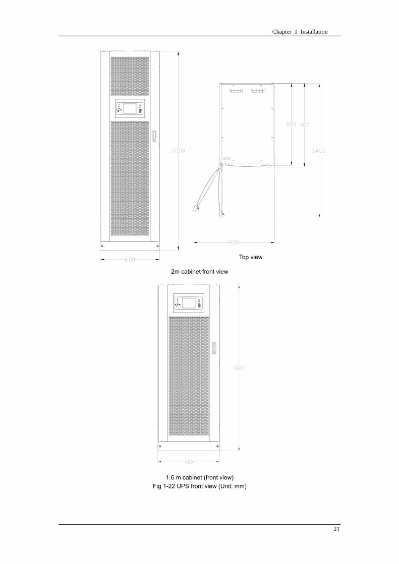
Chapter 1 Installation
21
顶视图
2m cabinet front view
16 m cabinet (front view)
Fig 1-22 UPS front view (Unit mm)
Top view
Chapter 1 Installation
22
A
2m cabinet
A
16m cabinet
Fig 1-23 UPS back view
Chapter 1 Installation
23
A
A处放大
Fig 1-24 UPS front view
Amplification of A
24 Chapter 2 Operations
24
Chapter 2 Operations
This chapter introduces the basic knowledge of UPS operations including working principle
operation mode battery management and protection
Warning Hazardous mains voltage andor battery voltage present(s)behind the protective cover
The components that can only be accessed by opening the protective cover with tools cannot be
operated by user
Only qualified service personnel are authorized to remove such covers
21 Introduction
UPS provides the critical load (such as communication and data processing equipment) with high
quality uninterruptible AC power The power from UPS is free from voltage and frequency variations and
disturbances (interruption and spike) experienced at the Mains AC input supply
This is achieved through high frequency double conversion power pulse width modulation (PWM)
associated with full digital signal processing control (DSP) which features high reliability and
convenience for use
211 Principle
As shown in fig 2-1 the AC input mains source is supplied at UPS input and converted into a DC
source This DC source feeds the Inverter that converts the DC source into a clean and input
independent AC source The battery powers the load through the inverter in case of an AC input mains
power failure The utility source can also power the load through the static bypass
When the UPS needs maintenance or repair the load can be transferred to maintenance bypass
without interruption and the power module and bypass module can be removed for maintenance
Chapter 2 Operations 25
25
Fig 2-1 System principle framework
212 Bypass Module
The circuit blocks labeled ldquobypass modulerdquo in fig 2-1 contain electronically controlled switching
circuits that enable the critical load to be connected to either the inverter output or to a bypass power
source via the static bypass line During normal system operation the load is connected to the inverter
but in the event of a UPS overload or inverter failure the load is automatically transferred to the static
bypass line
To provide a clean (no-break) load transfer between the inverter output and static bypass line the
inverter output and bypass supply must be fully synchronized during normal operating conditions This is
achieved through the inverter control electronics which makes the inverter frequency track that of the
static bypass supply provided that the bypass remains within an acceptable frequency window
A manually controlled maintenance bypass supply is incorporated into the UPS design It enables
the critical load to be powered from the utility (bypass) supply while the UPS is shut down for routine
maintenance
Note
When the UPS is operating in bypass mode or on maintenance bypass the connected equipment is
not protected from power failures or surges and sags
22 Operation Mode
The MD UPS is an on-line double-conversion reverse-transfer UPS that permits operation in these
modes
Normal mode
26 Chapter 2 Operations
26
Battery mode
Auto-Restart mode
Bypass mode
Maintenance mode (manual bypass)
ECO mode
Frequency converters mode
221 Normal Mode
The UPS inverter power modules continuously supplies the critical AC load The rectifiercharger
derives power from the AC mains input source and supplies DC power to the inverter while
simultaneously FLOAT or BOOST charging its associated backup battery
222 Battery Mode
Upon failure of the AC mains input power the inverter power modules which obtains power from the
battery supplies the critical AC load There is no interruption in power to the critical load upon failure
After restoration of the AC mains input power the ldquoNormal Moderdquo operation will continue automatically
without the necessity of user intervention
Note UPS can also be started through battery (charged) mode via battery cold start function upon
failure of the AC mains Therefore the battery power can be used independently to improve the
utilization rate of UPS
223 Auto-Restart Mode
The battery may become exhausted following an extended AC mains failure The inverter shuts
down when the battery reaches the End of Discharge voltage (EOD) The UPS may be programmed to
ldquoAuto Recovery after EODrdquo after a delay time if the AC mains recovers This mode and any delay time
are programmed by the commissioning engineer
During the process of delay time the battery will be charged by UPS to prevent any risks to load
equipment from future mains failure
224 Bypass Mode
If the inverter overload capacity is exceeded under normal mode or if the inverter becomes
unavailable for any reason the static transfer switch will perform a transfer of the load from the inverter
to the bypass source with no interruption in power to the critical AC load
225 Maintenance Mode
A manual bypass switch is available to ensure continuity of supply to the critical load when the UPS
becomes unavailable eg during a maintenance procedure
Note This manual bypass switch is fitted in all UPS modules Transfer UPS system to bypass
module for power supply first then close maintenance bypass switch Q2 followed by Q1 and Q3
Warning hazard may occur after transferring to maintenance bypass
After UPS being transferred to maintenance bypass power module and bypass module do not work
no display on LCD and input and output terminals as well as N bus are electrically connected
Chapter 2 Operations 27
27
226 ECO Mode
If economical (ECO) mode is selected the double-conversion UPS will stop to work so as to save
energy During the operation of ECO mode the load power will be supplied by bypass preferentially
When bypass power is within the range of normal frequency and voltage load power will be supplied by
bypass or the system will transfer to inverter input followed by load power interruption which extends
within 34 of the utility period Eg when the frequency is 50Hz the interruption time will be less than
15ms when the frequency is 60Hz the time will be less than 125ms
227 Frequency Converters Mode
If the frequency converter configuration is used by UPS it will provide 50Hz or 60Hz stable output
frequency The range of output frequency is 40Hz~70Hz Under this mode static bypass is unavailable
but battery can be selected according to the actual requirements of battery mode
23 Battery Management
231 Normal Function
The following functions should be fitted by commissioning engineers with specified software
1 Constant current boost charging
Current can be set up
2 Constant voltage boost charging
Voltage of boost charging can be set as required by the type of battery
For Valve Regulated Lead Acid (VRLA) batteries maximum boost charge voltage should not
exceed 24V cell
3 Float charge
Voltage of float charging can be set as required by the type of battery
For VRLA float charge voltage should be between 22V to 23V
4 Float charge temperature compensation (optional)
A coefficient of temperature compensation can be set as required by the type of battery
5 End of discharge (EOD) protection
If the battery voltage is lower than the EOD the battery converter will shut down and the battery is
isolated to avoid further battery discharge EOD is adjustable from 16V to 175V per cell (VRLA) or 09
to 11 V per cell
6 Battery low warning time
It is adjustable between 3 and 60 minutes The default is 5 minutes
232 Advanced Functions (Battery Self-checking and Maintenance)
At periodic intervals 20 of the rated capacity of the battery will be discharged automatically and
the actual load must exceed 20 of the rated UPS (KVA) capacity If the load is less than 20
auto-discharge cannot be executed The periodic interval can be set from 30 to 360 days The battery
self-test can be disabled
ConditionsmdashBattery at float charge for at least 5 hours load equal to 20~100 of rated UPS capacity
TriggermdashManually through the command of ldquoBattery Maintenance Testrdquo in LCD panel or automatically
Battery Self-Test Intervalmdash30-360 days (default setting is battery self-test disabled)
28 Chapter 2 Operations
28
24 Battery Protection
The following functions should be fitted by commissioning engineers with specified software
1 Battery Low Pre-warning
The battery under voltage pre-warning occurs before the end of discharge After this pre-warning
the battery should have the capacity for 3 remaining minutes discharging with full load The time is user
configured from 3 to 60 minutes
2 Battery discharge (EOD)off protection
If the battery voltage is lower than the EOD the battery converter will be shut down EOD is
adjustable from 16V to 175V per cell (VRLA) or 09 to 11 V per cell (NiCd)
3 Battery Circuit Breaker (BCB) Alarm
The alarm occurs when the battery disconnect device disconnects The external battery connects to
the UPS through the external battery circuit breaker The circuit breaker is manually closed and tripped
by the UPS control circuit
Chapter 3 Operation Instructions 29
29
Chapter 3 Operating Steps
This chapter describes UPS operation instructions in detail
All functional keys and LED display involved in operation instructions please refer to chapter 4
During operation the buzzer alarm may occur at any time Select ldquomuterdquo on LED to muffle the audible
alarm
Warning-Hazardous mains voltage andor battery voltage present(s)behind the protective cover
1 The components that can only be accessed by opening the protective cover with tools cannot be
operated by user
2 Only qualified service personnel are authorized to remove such covers
31 Power Switches
As shown in fig 3-1 open the front door of UPS the power switch is visible which includes input
switch output switch and maintenance bypass switch (with anti-misoperation stop plate)
输入开关 输出开关
维修旁路开关
Fig 3-1 Power switch location diagram
32 UPS Start-up
The UPS system only has a maintenance bypass isolating switch and all the other transfers are
processed automatically by internal control logics
Input switch Output switch
Maintenance bypass switch
30 Chapter 3 Operating Instructions
30
321 Normal Module Start
This procedure must be followed when turning on the UPS from a fully powered down condition
The operating procedures are as follows
Warning
This procedure results in mains voltage being applied to the UPS output terminals If any load
equipment is connected to the UPS output terminals please check with the load user that it is safe to
apply power If the load is not ready to receive power then ensure that it is safely to close the output
switch of external distribution cabinet
1 Close UPS output switch and input switch in turns
The LCD starts up at this time The Rectifier indicator flashes during the startup of rectifier The
rectifier enters normal operation state and after about 30s the rectifier indicator goes steady green After
initialization the bypass static switch closes The UPS Mimic LEDs will indicate as shown in table 3-1
Table 3-1 Indicator status
LED Status
Rectifier indicator Green
Battery indicator Red
Bypass indicator Green
Inverter indicator Off
Load indicator Green
Status indicator Green
Note
The output circuit breaker must be closed first followed by input circuit breaker or the rectifier cannot
be started and alarm ldquorectifier failurerdquo
The inverter starts up at this time the inverter indicator flashes After the rectifier enters normal
operation state UPS power supply will transfer from bypass to inverter then the bypass indicator turns
off and load indicator lights The status of indicators is shown in table 3-2
Table 3-2 Indicator Status
LED Status
Rectifier indicator Green
Battery indicator Red
Bypass indicator Off
Inverter indicator Green
Load indicator Green
Status indicator Green
Close external battery switch again battery indicator turns off a few minutes later the battery will be
charged by UPS which will enter normal mode operation The indicator status is shown in table 3-3
Table 3-3 Indicator status
LED Status
Rectifier indicator Green
Battery indicator Green
Bypass indicator Off
Inverter indicator Green
Load indicator Green
Status indicator Green
322 Operating steps of Battery cold Start
1 Check if the batteries have been connected close the external battery switch
Chapter 3 Operation Instructions 31
31
2 Press the red start-up button of battery under the rectifier input circuit breaker for 3 seconds (see fig
3-2)
The LCD starts up at this time The green battery indicator flashes The rectifier enters normal
operation states and after about 30s the battery indicator goes steady green
3 The inverter starts up automatically the green inverter indicator flashes The output of inverter
appears after 60s The UPS works on battery mode
32 Chapter 3 Operating Instructions
32
电池启动按钮
Fig 3-2 Position diagram of battery startup button
Battery startup button
Chapter 3 Operation Instructions 33
33
33 Procedure for Switching between Operation Modes
331 Procedure for Switching the UPS into Battery mode from Normal Mode
Open input switch to cut off the mains UPS enters the battery mode If UPS should be switched to
normal mode wait for a few seconds before close input switch so as to supply the mains again 10s
later the rectifier will start up automatically to supply power to the inverter
332 Procedure for Switching the UPS into Bypass mode from Normal Mode
Select ldquoTran Byprdquo on the LCD or press ldquooffrdquo buttons of each power module in turn
Note
In bypass mode the load is directly fed by the mains power instead of the pure AC power from the
inverter
333 Procedure for Switching the UPS into Normal from Bypass Mode
Select exit bypass mode on the LCD
334 Procedure for Switching the UPS into a Maintenance Bypass from Normal Mode
In normal operation this operation instruction will switch the load from inverter input to maintenance
bypass
Caution
Before making this operation read messages on display to be sure that bypass supply is regular and
the inverter is synchronous with it so as not to have a risk of a short interruption in powering the load
1 Press ldquoTran Byprdquo on the LCD or press ldquooffrdquo on each power module in turns
If press rdquoTran Byprdquo on the LCD the inverter indicator will flash green and the buzzer will alarm
If press ldquooffrdquo on each power module in turns the inverter indicator will go off and the buzzer will
alarm
The load will be transferred to static bypass and the inverter is closed
2 Close maintenance bypass switch Q2 the load power will be supplied by maintenance bypass and
then open the inverter circuit breaker Q1 output switch Q3 and battery switch
Warning
If you need to maintain the module wait for 10 minutes to let the DC bus capacitor fully discharge
before removing corresponding module
335 Procedure for Switching the UPS into Normal from a Maintenance Bypass Mode
This procedure can transfer the load to normal main mode when the UPS is operating under the
maintenance bypass mode
1 Close output switch Q3 and main switch Q1
The bypass indicator goes green and the load power will be supplied by bypass and maintenance
bypass
2 Open maintenance bypass switch Q2
34 Chapter 3 Operating Instructions
34
The load power is supplied by bypass In the meantime the rectifier starts up rectifier indicator goes
green 30s later at this time the inverter will start up automatically and transfer to inverter mode 1 min
later automatically
3 Close external battery switch the battery indicator goes off Check if the battery voltage on LCD
display is normal
34 Procedure for Completely Powering down a UPS
If you need to power down the UPS completely follow the procedures in section 334 to transfer the
UPS from normal mode to maintenance bypass mode
If you need to isolate the UPS from the AC power supply you should open the external input switch
35 EPO Procedure
The EPO button on UPS operator control and display panel is designed to switch off the UPS in
emergency conditions (eg fire flood etc)To achieve this just press the EPO button and the system
will turn off the rectifier inverter and stop powering the load immediately (including the inverter and
bypass output) and the battery stops charging or discharging
If the input utility is present the UPS control circuit will remain active however the output will be
turned off To completely isolate the UPS you need to open the external mains input supply to the UPS
rack
36 Language Selection
The LCD is available in two languages Chinese English and Korean
The language can be selected through LCD prompt window
37 Control Password
When the LCD displays ldquoinput control password 1rdquo the initial password is 12345678
Chapter 4 Operator Control and Display Panel 35
35
Chapter 4 Operator Control and Display Panel
This chapter introduces the functions and operation instructions of the parts on UPS operator control
and display panel in detail and provides LCD display information including LCD display types detailed
menu information prompt window information and UPS alarm list
41 Introduction
The operator control and display panel is located on the front panel of the UPS Through this LCD
panel the operator can operate and control the UPS and check all measured parameters UPS and
battery status and event and alarm logs The operator control panel is divided into three functional areas
as shown in fig 4-1 mimic current path LCD display amp Menu keys and Control and Operation Keys The
detailed description of parts on operator control and display panel is shown in table 4-1
Fig 4-1 UPS operator control and display panel
Table 4-1 Description of UPS operator control and display panel
Part No Function Button Function
REC Rectifier indicator EPO EPO switch
BAT Battery indicator TAB switch
BYP Bypass indicator ENTER confirm
INV Inverter indicator ESC exit
OUTPUT Load indicator
STATUS Status indicator
36 Chapter 4 Operator Control and Display Panel
36
411 LED Indicator
The LEDs shown on the mini current path represent the various UPS power paths and show the
current UPS operating status The status description of indicators is shown in table 4-2
Table 4-2 Status description of indicator
Indicator State Purpose
Rectifier
indicator
Steady green Rectifier normal for all modules
Flashing green Rectifier for at least on module normal mains normal
Steady red Rectifier fault
Flashing red Mains abnormal for at least one module
Off Rectifier not operating
Battery
indicator
Steady green Battery charging
Flashing green Battery discharging
Steady red
Battery abnormal (battery failure no battery or battery reverse) or
battery converter abnormal (failure over current or over temperature)
EOD
Flashing red Battery low voltage
Off Battery and battery converter normal battery not charging
Bypass
indicator
Steady green Load power supplied by bypass
Steady red Bypass power abnormal or out of normal range or static bypass
switch fault
Flashing red Bypass voltage abnormal
Off Bypass normal
Inverter
indicator
Steady green Load power supplied by inverter
Flashing green Inverter On start synchronization of standby (ECO mode) for at least
one module
Steady red System power not supplied by inverter inverter fault for at least one
module
Flashing red System power supplied by inverter inverter fault for at least one
module
Off Inverter not operating for all modules
Load
indicator
Steady green UPS output ON and normal
Steady red UPS output overload and overtime or output short or output no power
supply
Flashing red Overload output of UPS
Off No output of UPS
Status
indicator
Steady green Normal operation
Steady red Failure
412 Audible Alarm (buzzer)
There are two different types of audible alarm during UPS operation as shown in table 4-3
Table 4-3 description of audible alarm
Alarm Purpose
Two short alarm with
a long one
when system has general alarm (for example AC fault) this audible alarm
can be heard
Continuous alarm When system has serious faults (for example fuse or hardware fault) this
audible alarm can be heard
Chapter 4 Operator Control and Display Panel 37
37
413 Functional Keys
There are 4 functional keys on operator control and display panel which are used together with LCD
The functions description is shown in table 4-4
Table 4-4 Functions of functional keys
Functional key Functions
EPO switch To cut off the load power to shut down the rectifier inverter static
bypass and battery
TAB switch
ENTER confirm
ESC exit
42 LCD Display Type
Following the self-check of UPS LCD display the main LCD display is shown as fig 4-2 which can
be divided into three display windows system information data command and current record
Fig 4-2 Main LCD display
The description of LCD icon is shown in table 4-5
Table 4-5 Description of LCD icons
Icon Description
Bypass parameter
UPS system
information
window
Data
command
window
Current
record
window
38 Chapter 4 Operator Control and Display Panel
38
Icon Description
Main input parameter
History file system information
Function setting (display calibration password setting time setting date format
communication protocol and language setting) system setting (used by product
maintainers)
Battery data battery parameter setting (used by service staff)
Test (battery self-test battery maintenance)
Functional keys used by service staff (fault clearing history file clearing noise
clearing manual switch of bypass) userrsquos setting (system mode machine
number system ID output voltage adjustment frequency tracing speed
frequency tracing limit)
Output parameter
Load
Noise clearing noise clearing cancel
Log view page updown
Select a icon on LCD as shown in fig 4-3 to view the UPS parameter represented by this icon eg
select the LCD will display the data of system main input
Chapter 4 Operator Control and Display Panel 39
39
Fig 4-3 Select data
Or select and confirm a module as shown in fig 4-4 the LCD will display the
operating status of this module
Fig 4-4 Select a module
40 Chapter 4 Operator Control and Display Panel
40
Select in the operating status of a module to view the main input data of this module
Select in the operating status of a module to view the main output data of this module
Select in the operating status of a module to view the load data of this module
Select in the operating status of a module to view the maintenance code and module
software code of this module
Select to return to the previous page
Select to return to the home page
Default display
During the operation of system if therersquos no alarm in 2 min the system will display default After a
short delay the backlight of LCD display goes off press any key to reactivate the display
43 Detailed Description of Menu Items
The LCD main display shown in fig 4-2 is described in details below
UPS information window
UPS information window display the current time and UPS name The information of the window is
not necessary for the user to operate The information of this window is given in table 4-6
Table 4-6 Description of items in UPS system information window
Display contents Meaning
MD12020 UPS Name
1200 Current Time (format 24 hours hours minute)
UPS menu and data window
UPS menu window displays the menu name of data window while the data window displays the
related contents of selected menu in menu window Select UPS menu and data window to browse
related parameters of UPS and set related functions The details are given in table 4-7
Table 4-7 Item description of UPS menu and data window
Menu name Menu item Meaning
Main input
V phase(V) V phase
I phase(A) I phase
Freq(Hz) Input frequency
PF Power factor
Bypass input
V phase(V) V phase
Freq (Hz) Bypass frequency
I phase(A) I phase
PF Power factor
AC output
V phase(V) V phase
I phase(A) I phase
Freq (Hz) Output frequency
PF Power factor
This UPS Sout (kVA) Sout Apparent Power
Chapter 4 Operator Control and Display Panel 41
41
Menu name Menu item Meaning
modulersquos
load
Pout (kW) Pout Active Power
Qout (kVAR) Qout Reactive Power
Load () Load (The percentage of the UPS rating load)
Battery data
Environmental
Temp Environmental Temp
Battery
voltage(V) Battery bus voltage
Battery current
A) Battery bus current
Battery
Temp() Battery Temp
Remaining Time
(Min) Remaining battery backup time
Battery capacity
() The percentage compared with new battery capacity
battery
equalized
charging
Battery is equalized charging
battery float
charging Battery is float charging
Battery
disconnected Battery is not connected
Current
record (current alarm)
Display all current alarm The alarm list displayed on LCD of
UPS operator control and display panel please refer to table 4-9
History
record (history alarm)
Display all history alarm The alarm list displayed on LCD of
UPS operator control and display panel please refer to table 4-9
Menu
Language
(language
option) 2 languages can be selected
Settings
Display
calibration Adjust the accuracy of LCD display
Date format set MM DD YYYY and YYYY MM DD formats can be selected
Date amp Time DateTime set
Language set User can set the language (Chinese and English)
Communication
mode
Set communication mode MODBUS Power protocol and
company custom protocol modes can be selected Power
protocol mode can be divided into equipment address baud
rate set MODBUS protocol mode can be divided into
communication mode (RTUASCⅡ) equipment address
baud rate and check-bit set Company custom protocol mode
is the customed protocol of the company no option is
available
Control
password set User can modify control password 1
Test
Command
(Battery Test
Control
Battery
maintenance
test
This test will lead to the battery being partly discharged to
activate battery at the same time the approximate battery
capacity will be obtained Bypass must be in normal condition
the battery capacity should be above 25
42 Chapter 4 Operator Control and Display Panel
42
Menu name Menu item Meaning
Battery
self-check test
UPS switches to battery discharge for discharging to test if the
battery is normal Bypass must be in normal condition the
battery capacity should be above 25
Stop testing Manually Stop the test including maintenance test capacity test
UPS system
information
Monitoring
software version Provide monitoring software version
Rectified
software version Provide rectified software version
Inverted
software version Provide inverted software version
Serial No The serial no set when delivery from the factory
Rated
information Network setting of system operating
Module type Type of the module
44 Alarm List
The follow table 4-8 gives the complete list of all the UPS events displayed by history record window
and current record window
Table 4-8 Alarm List
Alarm Explanation
UPS power supply The system is in normal inverted power supply status
Bypass power
supply The system is in bypass power supply status
No power supply System no output
Battery equalized
charging Battery is in boost charging
Battery float
charging Battery is in float charging
Battery discharging The system is operating in battery discharging status
Battery connected Battery is connected
Battery
disconnected Battery is not connected
Maintenance circuit
breaker close Maintenance circuit breaker is close
Maintenance circuit
breaker open Maintenance circuit breaker is open
Emergency
shutdown System emergency shutdownEPO
Generator
connected External generator is connected
Mains abnormal Input mains abnormal
Bypass phase
conversion Bypass input phase converse
Bypass voltage
abnormal Bypass input voltage abnormal
Bypass fault Bypass fault
Bypass overload Bypass output is overload
Up to bypass
overtime of Bypass is overtime of overload
Chapter 4 Operator Control and Display Panel 43
43
Alarm Explanation
overload
Bypass frequency
tracing exceeds Bypass frequency is out of the tracing range
Switch times up to
in this hour
The times of switch between bypass and inverter exceeds 5 times in the latest
hour
Output short System output short
Battery EOD Battery voltage achieves shutdown point
Battery self-check The system enters battery self-check mode
Battery self-check
success Battery normal during system self-check
Battery manual
check failure Battery fault during system self-check
Battery
maintenance The system is in battery maintenance status
Battery
maintenance
success
Battery maintenance status completes
Battery
maintenance failure Battery maintenance process is not normal
Stop testing Battery self-check or battery maintenance status stops
Fault clearing Clear the alarmed fault
Delete history
record Delete all history record
N communication
node connected N module is connected to UPS system
N communication
node disconnected N module is not connected to UPS system
N rectifier fault N module rectifier fault
N inverter fault N module inverter fault
N rectifier
overheat N module rectifier overheat
N fan fault N module fan fault
N output overload N module output overload
N overtime of
overload N module output overtime of overload
N inverter
overheat N module inverter overheat
Inverter power
supply ban Inverter power ban supply
Manual switch of
bypass Switch the system to bypass output manually
Cancel manual
switch of bypass Switch the system from bypass to inverter output manually
Battery low voltage Battery low voltage
Battery reversal Battery polarity reversal
N inverter
protection N module inverter protection
Input N line
disconnected System input N line is not connected
Bypass fan fault Bypass module fan fault
N manual N module manual power off
44 Chapter 4 Operator Control and Display Panel
44
Alarm Explanation
shutdown
Chapter 5 Maintenance 45
45
Chapter 5 Installation of Parallel Operation System
The parallel operation system is installed as required by the installation procedures of the single
system and this chapter
The single devices are put parallel and connected as shown in fig 5-1 and the difference between
the lengths of the output cables of the single devices is not more than 10m It is recommended to use an
external bypass cabinet to facilitate maintenance and system testing
Fig 5-1 Typical 1+N parallel operation system
Note when the load exceeds is the capacity of the single device the maintenance bypass
switch CB3 must be removed
The cables for the parallel operation provide double insulation shielding up to 30m long the control
cables for the parallel operation must be connected with all single devices to form a closed loop as
shown in fig5-2
Other power supplies
Rectifier
Charger Inverter Inverter
Output power supply
Load connected
Mains power input L1 L2 L3 N terminal
Mains power inputL1 L2 L3 N terminal
Rectifier
Charger
46 Chapter 5 Maintenance
46
Fig5-2 parallel cables
Chapter 5 Maintenance 47
47
Chapter 6 Maintenance
This chapter introduces UPS maintenance including the maintenance instructions of power module
monitoring bypass module and the change method of dust filter
61 Instruction to Power Bypass and Output Power Distribution
Module
611 Precautions
1 Only maintaining engineers can maintain the power module and monitoring bypass module
2 In principle the power module and bypass module should be disassembled from top to bottom so
as to prevent any inclination from high gravity centre of the cabinet
3 To ensure the safety before maintaining power module and bypass module be sure to use a
multimeter to measure the DC bus capacitor voltage and ensure the voltage is below 60V before
operation and use a multimeter to measure the voltage between operating parts and the earth to
ensure the voltage is lower than hazardous voltage ie DC voltage is lower than 60Vdc and AC
maximum Voltage is lower than 424Vac
4 Bypass module doesnrsquot support any hot insertion and extraction only when UPS is in maintenance
bypass mode or UPS is completely power off can the bypass module be disassembled
5 The module can be maintained 10 mins after extracting power module and bypass module which
can be inserted into the cabinet 10 mins later
612 Instruction to Power Module
Suppose UPS were in normal mode and bypass were normal a module shall be maintained at
first
1 Press OFF of the module with a pin point or other tiny matter the module will shut down
automatically and exit the system
Note ensure if the remaining module will be overload when exiting a module If therersquos any risk of
overload transfer the whole UPS system to bypass followed by other operations
2 Take off the fixing bolt on the two sides of front and back plate of power module 10 mins later
extract the module from the cabinet
3 After maintaining the module push the module into the equipment cabinet (the interval between
two modules shall be more than 10s) fix the screw on the two sides Then the module will be
connected to UPS system automatically
613 Instruction to Bypass Module
Suppose UPS were in normal mode and the bypass were normal
1 Select LCD touch screen manual switch of bypass the UPS power will be supplied by bypass
2 Close maintenance bypass switch the UPS power will be supplied by maintenance bypass
3 Open UPS output switch and input switch
4 Open external battery switch
48 Chapter 5 Maintenance
48
5 Take off the fixing bolt at the two sides of front board of bypass module extract the front cable
assembly of the module and extract the module from the cabinet
6 After maintaining the module insert the module into the cabinet tighten the screw at the two sides
and connect the front cable assembly of manufacturerrsquos module
7 Close UPS output switch and input switch in turn
2 mins later bypass indicator on the operator control and display panel lights on which indicates
the normal power supply of bypass
8 Open maintenance bypass switch the inverter starts automatically 60s later the UPS will transfer
to normal mode
62 Replacing Dust Screen (optional)
As shown in fig 5-1 there are 3~4 dust filters on the back of UPSrsquo front door each screen is held in
place by a bracket on either side of each filter The procedure of replacing each filter is as follows
1 Open the UPSrsquo front door and locate the filters on the back side of the front door
2 Remove one bracket
3 Remove the dust screen to be replaced and insert the clean one
4 Reinstall the bracket
防尘网固定条
Fig 5-1 Dust screen on the back side of UPS front door
Bracket
Dust screen
Appendix 2 Toxic or Hazardous Materials or Elements Identification Table 49
49
Chapter 7 Product Specification
This chapter provides UPS product specification
71 Applicable Standards
The UPS has been designed to conform to the following European and international standards
Table 6-1 Compliance with European and International Standards
Item Normative reference
General safety requirements for UPS
used in operator access areas EN50091-1-1IEC62040-1-1AS 62040-1-1
Electromagnetic compatibility (EMC)
requirements for UPS EN50091-2IEC62040-2AS 62040-2(C3)
Method of specifying the performance
and test requirements of UPS EN50091-3IEC62040-3AS 62040-3(VFI SS 111)
Note The above mentioned product standards incorporate relevant compliance clauses with generic
IEC and EN standards for safety (IECENAS60950) electromagnetic emission and immunity
(IECEN AS61000 series) and construction (IECENAS60146 series and 60950)
72 Environmental Characteristics
Table 6-2 Environmental Properties
Items Unit Requirements
Acoustic noise level at 1
meter dB 550
Altitude of Operation m le1000m above sea level derate power by 1 per 100m
between 1000m and 2000m
Relative Humidity RH 0 to 95 non condensing
Operating Temperature 0 to 40 deg Battery life is halved for every 10degC increase
above 20degC
UPS Storage-Transport
Temperature -20~70
Recommended Battery
Storage Temperature -20~30 (20degC for optimum battery storage)
73 Mechanical Characteristics
Table 6-3 Mechanical Properties
Cabinet Specification Unit MD6010 MD9015
MD12020
MD10010 MD15015
MD20020
Mechanical Dimension
WtimesDtimesH mm 600times900times1600 600times900times2000
Weight kg 151 182
Color NA Black
Protection Level
IEC(60529) NA IP20
50 Chapter 5 Maintenance
50
Module type Unit MU10 MU15 MU20
Mechanical Dimension
WtimesDtimesH mm 440times590times134
Weight kg 21 22 22
Color NA Black
74 Electrical Characteristics (Input Rectifier)
Table 6-4 Rectifier AC input (mains)
Items Unit Parameter
Rated AC Input
Voltage Vac
380400415(three-phase and sharing neutral with the
bypass input)
Input voltage range Vac -40~+25
Frequency2 Hz 5060(range 40Hz~70Hz)
Power factor kWkVA full load 099
THD THDI 3
75 Electrical Characteristics (Intermediate DC Link)
Table 6-5 Battery
Items Unit Parameters
Battery bus
voltage Vdc Nominal plusmn240V one-side range 198V~288V
Quantity of
lead-acid cells Nominal 40=[1 battery(12V) ] 240=[1 battery(2V) ]
Float charge
voltage Vcell(VRLA)
225Vcell(selectable from 22Vcell~235Vcell)
Constant current and constant voltage charge mode
Temperature
compensation mVcl -30(selectable from 0~-50 25 or 30 or inhibit)
Ripple voltage V float le1
Ripple current C10 le5
equalized
charge voltage VRLA
24Vcell(selectable from 230Vcell~245Vcell)
Constant current and constant voltage charge mode
final
discharging
voltage
Vcell(VRLA)
165Vcell(selectable from 160Vcell ~ 1750Vcell) 06C
discharge current
175Vcell (selectable from 165Vcell ~ 18Vcell) 015C
discharge current
(EOD voltage changes linearly within the set range according to
discharge current)
Battery Charge Vcell 24Vcell(selectable from 23Vcell~245Vcell)
Constant current and constant voltage charge mode
Battery
Charging Power
Max Current
kW 10 UPS capacity (selectable from 0~20 UPS capacity)
Appendix 2 Toxic or Hazardous Materials or Elements Identification Table 51
51
76 Electrical Characteristics (Inverter Output)
Table 6-6 Inverter Output (to important load)
Rated
capacity(kVA) Unit 10~200
Rated AC voltage1 Vac 380400415(three-phase four-wire and sharing neutral with the
bypass)
Freqency2 Hz 5060
overload
110 load 1 hour
125 load 10min
150 load 1min
>150 load 200ms
Fault current 340 short current limitation for 200ms
Non linear load
capability 3 100
Neutral current
capability 170
Steady state
voltage stability
plusmn1(balanced load)
plusmn15(100 imbalance load)
Transient voltage
response 4 plusmn5
THD <15(linear load) <5(non linear load3)
Synchronization -
Window Rated frequency plusmn2Hz(selectable plusmn1~plusmn5Hz)
Max change rate of
synch frequency Hzs 1 selectable 01~5
Inverter voltage
range V(ac) plusmn5
Note
1 Factory setting is 380V Commissioning engineers can set to 400V or 415V
2 Factory setting is 50Hz Commissioning engineers can set to 60Hz
3 EN50091-3(1458) peak value factor is 3 1
4 IEC62040-3EN50091-3 including 0~100~0 load transient the recovery time is half
circle to within 5 of stable output voltage
52 Chapter 5 Maintenance
52
77 Electrical Characteristics(Bypass Mains Input)
Table 6-7 Bypass Mains Input
Rated
capacity(kVA) Unit 60 90 100 120 150 200
Rated AC
Voltage1 Vac
380400415
three-phase four-wire sharing neutral with the rectifier input and providing neutral
reference for the output
Rated current A
91380V
87400V
83415V
136380V
130400V
124415V
151380V
144400V
138415V
182380V
174400V
166415V
227380V
216400V
207415V
302380V
288400V
276415V
Overload
125 load long term
130 load 1 hour
150 load 6min
1000 load 100ms
Superior
protection
bypass line
NA Thermal-magnetic breaker the capacity is 125 of rated current output
IEC60947-2 curve C
Current rating
of neutral cable A 17timesIn
Frequency2 Hz 5060
Switch time
(between
bypass and
inverter)
ms Synchronized switch le1ms
Bypass voltage
tolerance Vac
Upper limit +10+15or+20 default +20
Lower limit -10 -20 -30 or-40 default-20
(acceptable stable bypass voltage delay 10s)
Bypass
frequency
tolerance
plusmn25 plusmn5 plusmn10 or plusmn20 default plusmn10
Synchronizatio
n-Window Hz Rated frequencyplusmn2Hz (selectable from plusmn05Hz~plusmn5Hz)
Note
1 Factory setting is 400V Commissioning engineers can set to 380V or 415V
2 Factory setting is 50Hz Commissioning engineers can set to 60Hz For example UPS is set to frequency
inverter mode and then bypass status will be neglected
78 Efficiency
Table 6-8 Efficiency Loss and Air Exchange
Rated Efficiency (kVA) Unit 10~200kVA
Normal mode(dual conversion) 95
ECO mode 99
Battery discharging efficiency (DCAC) (battery at nominal voltage 480Vdc and full-rated linear load)
battery mode 95
Appendix 2 Toxic or Hazardous Materials or Elements Identification Table 53
53
Appendix A A Guidebook to Ordering and Selection of MU System
MD series UPS module can be divided into equipment cabinet and power module For the cabinet
lectotype please refer to the description in fig 6-1
Fig 6-1 Cabinet Selection
For single power module type please refers to the description in fig 6-2
Fig 6-2 Power Module Selection
Egg the requirements of a plant room are given below
The maximum power supply of the plant room is 120kVA however it is expected to be expanded to
200kVA in 3-5 years Therefore a 200kVA cabinet and 6 20kVA power module can be purchased to
constitute an uninterrupted 120kVA power system which can be expanded to 200kVA on-line The order
symbol is
1 set MD20020
6 set MU20
Option list
MD-SNMP card remote network monitoring card
MD-1600 dust filter dust screen for 16m cabinet
MD-2000 dust filter dust screen for 2m cabinet
Represents the capacity of a single power module
10 represents 10kVA
15 represents 15kVA
20 represents 20kVA
represents a single power module
Represents UPS system capacitypower module
06010 represents 60kVA10kVA
09015 represents 90kVA15kVA
12020 represents 120kVA20kVA
15015 represents 150kVA15kVA
20020 represents 200kVA20kVA
MD represents UPS cabinet
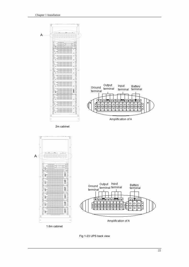
Chapter 1 Installation
22
A
2m cabinet
A
16m cabinet
Fig 1-23 UPS back view
Chapter 1 Installation
23
A
A处放大
Fig 1-24 UPS front view
Amplification of A
24 Chapter 2 Operations
24
Chapter 2 Operations
This chapter introduces the basic knowledge of UPS operations including working principle
operation mode battery management and protection
Warning Hazardous mains voltage andor battery voltage present(s)behind the protective cover
The components that can only be accessed by opening the protective cover with tools cannot be
operated by user
Only qualified service personnel are authorized to remove such covers
21 Introduction
UPS provides the critical load (such as communication and data processing equipment) with high
quality uninterruptible AC power The power from UPS is free from voltage and frequency variations and
disturbances (interruption and spike) experienced at the Mains AC input supply
This is achieved through high frequency double conversion power pulse width modulation (PWM)
associated with full digital signal processing control (DSP) which features high reliability and
convenience for use
211 Principle
As shown in fig 2-1 the AC input mains source is supplied at UPS input and converted into a DC
source This DC source feeds the Inverter that converts the DC source into a clean and input
independent AC source The battery powers the load through the inverter in case of an AC input mains
power failure The utility source can also power the load through the static bypass
When the UPS needs maintenance or repair the load can be transferred to maintenance bypass
without interruption and the power module and bypass module can be removed for maintenance
Chapter 2 Operations 25
25
Fig 2-1 System principle framework
212 Bypass Module
The circuit blocks labeled ldquobypass modulerdquo in fig 2-1 contain electronically controlled switching
circuits that enable the critical load to be connected to either the inverter output or to a bypass power
source via the static bypass line During normal system operation the load is connected to the inverter
but in the event of a UPS overload or inverter failure the load is automatically transferred to the static
bypass line
To provide a clean (no-break) load transfer between the inverter output and static bypass line the
inverter output and bypass supply must be fully synchronized during normal operating conditions This is
achieved through the inverter control electronics which makes the inverter frequency track that of the
static bypass supply provided that the bypass remains within an acceptable frequency window
A manually controlled maintenance bypass supply is incorporated into the UPS design It enables
the critical load to be powered from the utility (bypass) supply while the UPS is shut down for routine
maintenance
Note
When the UPS is operating in bypass mode or on maintenance bypass the connected equipment is
not protected from power failures or surges and sags
22 Operation Mode
The MD UPS is an on-line double-conversion reverse-transfer UPS that permits operation in these
modes
Normal mode
26 Chapter 2 Operations
26
Battery mode
Auto-Restart mode
Bypass mode
Maintenance mode (manual bypass)
ECO mode
Frequency converters mode
221 Normal Mode
The UPS inverter power modules continuously supplies the critical AC load The rectifiercharger
derives power from the AC mains input source and supplies DC power to the inverter while
simultaneously FLOAT or BOOST charging its associated backup battery
222 Battery Mode
Upon failure of the AC mains input power the inverter power modules which obtains power from the
battery supplies the critical AC load There is no interruption in power to the critical load upon failure
After restoration of the AC mains input power the ldquoNormal Moderdquo operation will continue automatically
without the necessity of user intervention
Note UPS can also be started through battery (charged) mode via battery cold start function upon
failure of the AC mains Therefore the battery power can be used independently to improve the
utilization rate of UPS
223 Auto-Restart Mode
The battery may become exhausted following an extended AC mains failure The inverter shuts
down when the battery reaches the End of Discharge voltage (EOD) The UPS may be programmed to
ldquoAuto Recovery after EODrdquo after a delay time if the AC mains recovers This mode and any delay time
are programmed by the commissioning engineer
During the process of delay time the battery will be charged by UPS to prevent any risks to load
equipment from future mains failure
224 Bypass Mode
If the inverter overload capacity is exceeded under normal mode or if the inverter becomes
unavailable for any reason the static transfer switch will perform a transfer of the load from the inverter
to the bypass source with no interruption in power to the critical AC load
225 Maintenance Mode
A manual bypass switch is available to ensure continuity of supply to the critical load when the UPS
becomes unavailable eg during a maintenance procedure
Note This manual bypass switch is fitted in all UPS modules Transfer UPS system to bypass
module for power supply first then close maintenance bypass switch Q2 followed by Q1 and Q3
Warning hazard may occur after transferring to maintenance bypass
After UPS being transferred to maintenance bypass power module and bypass module do not work
no display on LCD and input and output terminals as well as N bus are electrically connected
Chapter 2 Operations 27
27
226 ECO Mode
If economical (ECO) mode is selected the double-conversion UPS will stop to work so as to save
energy During the operation of ECO mode the load power will be supplied by bypass preferentially
When bypass power is within the range of normal frequency and voltage load power will be supplied by
bypass or the system will transfer to inverter input followed by load power interruption which extends
within 34 of the utility period Eg when the frequency is 50Hz the interruption time will be less than
15ms when the frequency is 60Hz the time will be less than 125ms
227 Frequency Converters Mode
If the frequency converter configuration is used by UPS it will provide 50Hz or 60Hz stable output
frequency The range of output frequency is 40Hz~70Hz Under this mode static bypass is unavailable
but battery can be selected according to the actual requirements of battery mode
23 Battery Management
231 Normal Function
The following functions should be fitted by commissioning engineers with specified software
1 Constant current boost charging
Current can be set up
2 Constant voltage boost charging
Voltage of boost charging can be set as required by the type of battery
For Valve Regulated Lead Acid (VRLA) batteries maximum boost charge voltage should not
exceed 24V cell
3 Float charge
Voltage of float charging can be set as required by the type of battery
For VRLA float charge voltage should be between 22V to 23V
4 Float charge temperature compensation (optional)
A coefficient of temperature compensation can be set as required by the type of battery
5 End of discharge (EOD) protection
If the battery voltage is lower than the EOD the battery converter will shut down and the battery is
isolated to avoid further battery discharge EOD is adjustable from 16V to 175V per cell (VRLA) or 09
to 11 V per cell
6 Battery low warning time
It is adjustable between 3 and 60 minutes The default is 5 minutes
232 Advanced Functions (Battery Self-checking and Maintenance)
At periodic intervals 20 of the rated capacity of the battery will be discharged automatically and
the actual load must exceed 20 of the rated UPS (KVA) capacity If the load is less than 20
auto-discharge cannot be executed The periodic interval can be set from 30 to 360 days The battery
self-test can be disabled
ConditionsmdashBattery at float charge for at least 5 hours load equal to 20~100 of rated UPS capacity
TriggermdashManually through the command of ldquoBattery Maintenance Testrdquo in LCD panel or automatically
Battery Self-Test Intervalmdash30-360 days (default setting is battery self-test disabled)
28 Chapter 2 Operations
28
24 Battery Protection
The following functions should be fitted by commissioning engineers with specified software
1 Battery Low Pre-warning
The battery under voltage pre-warning occurs before the end of discharge After this pre-warning
the battery should have the capacity for 3 remaining minutes discharging with full load The time is user
configured from 3 to 60 minutes
2 Battery discharge (EOD)off protection
If the battery voltage is lower than the EOD the battery converter will be shut down EOD is
adjustable from 16V to 175V per cell (VRLA) or 09 to 11 V per cell (NiCd)
3 Battery Circuit Breaker (BCB) Alarm
The alarm occurs when the battery disconnect device disconnects The external battery connects to
the UPS through the external battery circuit breaker The circuit breaker is manually closed and tripped
by the UPS control circuit
Chapter 3 Operation Instructions 29
29
Chapter 3 Operating Steps
This chapter describes UPS operation instructions in detail
All functional keys and LED display involved in operation instructions please refer to chapter 4
During operation the buzzer alarm may occur at any time Select ldquomuterdquo on LED to muffle the audible
alarm
Warning-Hazardous mains voltage andor battery voltage present(s)behind the protective cover
1 The components that can only be accessed by opening the protective cover with tools cannot be
operated by user
2 Only qualified service personnel are authorized to remove such covers
31 Power Switches
As shown in fig 3-1 open the front door of UPS the power switch is visible which includes input
switch output switch and maintenance bypass switch (with anti-misoperation stop plate)
输入开关 输出开关
维修旁路开关
Fig 3-1 Power switch location diagram
32 UPS Start-up
The UPS system only has a maintenance bypass isolating switch and all the other transfers are
processed automatically by internal control logics
Input switch Output switch
Maintenance bypass switch
30 Chapter 3 Operating Instructions
30
321 Normal Module Start
This procedure must be followed when turning on the UPS from a fully powered down condition
The operating procedures are as follows
Warning
This procedure results in mains voltage being applied to the UPS output terminals If any load
equipment is connected to the UPS output terminals please check with the load user that it is safe to
apply power If the load is not ready to receive power then ensure that it is safely to close the output
switch of external distribution cabinet
1 Close UPS output switch and input switch in turns
The LCD starts up at this time The Rectifier indicator flashes during the startup of rectifier The
rectifier enters normal operation state and after about 30s the rectifier indicator goes steady green After
initialization the bypass static switch closes The UPS Mimic LEDs will indicate as shown in table 3-1
Table 3-1 Indicator status
LED Status
Rectifier indicator Green
Battery indicator Red
Bypass indicator Green
Inverter indicator Off
Load indicator Green
Status indicator Green
Note
The output circuit breaker must be closed first followed by input circuit breaker or the rectifier cannot
be started and alarm ldquorectifier failurerdquo
The inverter starts up at this time the inverter indicator flashes After the rectifier enters normal
operation state UPS power supply will transfer from bypass to inverter then the bypass indicator turns
off and load indicator lights The status of indicators is shown in table 3-2
Table 3-2 Indicator Status
LED Status
Rectifier indicator Green
Battery indicator Red
Bypass indicator Off
Inverter indicator Green
Load indicator Green
Status indicator Green
Close external battery switch again battery indicator turns off a few minutes later the battery will be
charged by UPS which will enter normal mode operation The indicator status is shown in table 3-3
Table 3-3 Indicator status
LED Status
Rectifier indicator Green
Battery indicator Green
Bypass indicator Off
Inverter indicator Green
Load indicator Green
Status indicator Green
322 Operating steps of Battery cold Start
1 Check if the batteries have been connected close the external battery switch
Chapter 3 Operation Instructions 31
31
2 Press the red start-up button of battery under the rectifier input circuit breaker for 3 seconds (see fig
3-2)
The LCD starts up at this time The green battery indicator flashes The rectifier enters normal
operation states and after about 30s the battery indicator goes steady green
3 The inverter starts up automatically the green inverter indicator flashes The output of inverter
appears after 60s The UPS works on battery mode
32 Chapter 3 Operating Instructions
32
电池启动按钮
Fig 3-2 Position diagram of battery startup button
Battery startup button
Chapter 3 Operation Instructions 33
33
33 Procedure for Switching between Operation Modes
331 Procedure for Switching the UPS into Battery mode from Normal Mode
Open input switch to cut off the mains UPS enters the battery mode If UPS should be switched to
normal mode wait for a few seconds before close input switch so as to supply the mains again 10s
later the rectifier will start up automatically to supply power to the inverter
332 Procedure for Switching the UPS into Bypass mode from Normal Mode
Select ldquoTran Byprdquo on the LCD or press ldquooffrdquo buttons of each power module in turn
Note
In bypass mode the load is directly fed by the mains power instead of the pure AC power from the
inverter
333 Procedure for Switching the UPS into Normal from Bypass Mode
Select exit bypass mode on the LCD
334 Procedure for Switching the UPS into a Maintenance Bypass from Normal Mode
In normal operation this operation instruction will switch the load from inverter input to maintenance
bypass
Caution
Before making this operation read messages on display to be sure that bypass supply is regular and
the inverter is synchronous with it so as not to have a risk of a short interruption in powering the load
1 Press ldquoTran Byprdquo on the LCD or press ldquooffrdquo on each power module in turns
If press rdquoTran Byprdquo on the LCD the inverter indicator will flash green and the buzzer will alarm
If press ldquooffrdquo on each power module in turns the inverter indicator will go off and the buzzer will
alarm
The load will be transferred to static bypass and the inverter is closed
2 Close maintenance bypass switch Q2 the load power will be supplied by maintenance bypass and
then open the inverter circuit breaker Q1 output switch Q3 and battery switch
Warning
If you need to maintain the module wait for 10 minutes to let the DC bus capacitor fully discharge
before removing corresponding module
335 Procedure for Switching the UPS into Normal from a Maintenance Bypass Mode
This procedure can transfer the load to normal main mode when the UPS is operating under the
maintenance bypass mode
1 Close output switch Q3 and main switch Q1
The bypass indicator goes green and the load power will be supplied by bypass and maintenance
bypass
2 Open maintenance bypass switch Q2
34 Chapter 3 Operating Instructions
34
The load power is supplied by bypass In the meantime the rectifier starts up rectifier indicator goes
green 30s later at this time the inverter will start up automatically and transfer to inverter mode 1 min
later automatically
3 Close external battery switch the battery indicator goes off Check if the battery voltage on LCD
display is normal
34 Procedure for Completely Powering down a UPS
If you need to power down the UPS completely follow the procedures in section 334 to transfer the
UPS from normal mode to maintenance bypass mode
If you need to isolate the UPS from the AC power supply you should open the external input switch
35 EPO Procedure
The EPO button on UPS operator control and display panel is designed to switch off the UPS in
emergency conditions (eg fire flood etc)To achieve this just press the EPO button and the system
will turn off the rectifier inverter and stop powering the load immediately (including the inverter and
bypass output) and the battery stops charging or discharging
If the input utility is present the UPS control circuit will remain active however the output will be
turned off To completely isolate the UPS you need to open the external mains input supply to the UPS
rack
36 Language Selection
The LCD is available in two languages Chinese English and Korean
The language can be selected through LCD prompt window
37 Control Password
When the LCD displays ldquoinput control password 1rdquo the initial password is 12345678
Chapter 4 Operator Control and Display Panel 35
35
Chapter 4 Operator Control and Display Panel
This chapter introduces the functions and operation instructions of the parts on UPS operator control
and display panel in detail and provides LCD display information including LCD display types detailed
menu information prompt window information and UPS alarm list
41 Introduction
The operator control and display panel is located on the front panel of the UPS Through this LCD
panel the operator can operate and control the UPS and check all measured parameters UPS and
battery status and event and alarm logs The operator control panel is divided into three functional areas
as shown in fig 4-1 mimic current path LCD display amp Menu keys and Control and Operation Keys The
detailed description of parts on operator control and display panel is shown in table 4-1
Fig 4-1 UPS operator control and display panel
Table 4-1 Description of UPS operator control and display panel
Part No Function Button Function
REC Rectifier indicator EPO EPO switch
BAT Battery indicator TAB switch
BYP Bypass indicator ENTER confirm
INV Inverter indicator ESC exit
OUTPUT Load indicator
STATUS Status indicator
36 Chapter 4 Operator Control and Display Panel
36
411 LED Indicator
The LEDs shown on the mini current path represent the various UPS power paths and show the
current UPS operating status The status description of indicators is shown in table 4-2
Table 4-2 Status description of indicator
Indicator State Purpose
Rectifier
indicator
Steady green Rectifier normal for all modules
Flashing green Rectifier for at least on module normal mains normal
Steady red Rectifier fault
Flashing red Mains abnormal for at least one module
Off Rectifier not operating
Battery
indicator
Steady green Battery charging
Flashing green Battery discharging
Steady red
Battery abnormal (battery failure no battery or battery reverse) or
battery converter abnormal (failure over current or over temperature)
EOD
Flashing red Battery low voltage
Off Battery and battery converter normal battery not charging
Bypass
indicator
Steady green Load power supplied by bypass
Steady red Bypass power abnormal or out of normal range or static bypass
switch fault
Flashing red Bypass voltage abnormal
Off Bypass normal
Inverter
indicator
Steady green Load power supplied by inverter
Flashing green Inverter On start synchronization of standby (ECO mode) for at least
one module
Steady red System power not supplied by inverter inverter fault for at least one
module
Flashing red System power supplied by inverter inverter fault for at least one
module
Off Inverter not operating for all modules
Load
indicator
Steady green UPS output ON and normal
Steady red UPS output overload and overtime or output short or output no power
supply
Flashing red Overload output of UPS
Off No output of UPS
Status
indicator
Steady green Normal operation
Steady red Failure
412 Audible Alarm (buzzer)
There are two different types of audible alarm during UPS operation as shown in table 4-3
Table 4-3 description of audible alarm
Alarm Purpose
Two short alarm with
a long one
when system has general alarm (for example AC fault) this audible alarm
can be heard
Continuous alarm When system has serious faults (for example fuse or hardware fault) this
audible alarm can be heard
Chapter 4 Operator Control and Display Panel 37
37
413 Functional Keys
There are 4 functional keys on operator control and display panel which are used together with LCD
The functions description is shown in table 4-4
Table 4-4 Functions of functional keys
Functional key Functions
EPO switch To cut off the load power to shut down the rectifier inverter static
bypass and battery
TAB switch
ENTER confirm
ESC exit
42 LCD Display Type
Following the self-check of UPS LCD display the main LCD display is shown as fig 4-2 which can
be divided into three display windows system information data command and current record
Fig 4-2 Main LCD display
The description of LCD icon is shown in table 4-5
Table 4-5 Description of LCD icons
Icon Description
Bypass parameter
UPS system
information
window
Data
command
window
Current
record
window
38 Chapter 4 Operator Control and Display Panel
38
Icon Description
Main input parameter
History file system information
Function setting (display calibration password setting time setting date format
communication protocol and language setting) system setting (used by product
maintainers)
Battery data battery parameter setting (used by service staff)
Test (battery self-test battery maintenance)
Functional keys used by service staff (fault clearing history file clearing noise
clearing manual switch of bypass) userrsquos setting (system mode machine
number system ID output voltage adjustment frequency tracing speed
frequency tracing limit)
Output parameter
Load
Noise clearing noise clearing cancel
Log view page updown
Select a icon on LCD as shown in fig 4-3 to view the UPS parameter represented by this icon eg
select the LCD will display the data of system main input
Chapter 4 Operator Control and Display Panel 39
39
Fig 4-3 Select data
Or select and confirm a module as shown in fig 4-4 the LCD will display the
operating status of this module
Fig 4-4 Select a module
40 Chapter 4 Operator Control and Display Panel
40
Select in the operating status of a module to view the main input data of this module
Select in the operating status of a module to view the main output data of this module
Select in the operating status of a module to view the load data of this module
Select in the operating status of a module to view the maintenance code and module
software code of this module
Select to return to the previous page
Select to return to the home page
Default display
During the operation of system if therersquos no alarm in 2 min the system will display default After a
short delay the backlight of LCD display goes off press any key to reactivate the display
43 Detailed Description of Menu Items
The LCD main display shown in fig 4-2 is described in details below
UPS information window
UPS information window display the current time and UPS name The information of the window is
not necessary for the user to operate The information of this window is given in table 4-6
Table 4-6 Description of items in UPS system information window
Display contents Meaning
MD12020 UPS Name
1200 Current Time (format 24 hours hours minute)
UPS menu and data window
UPS menu window displays the menu name of data window while the data window displays the
related contents of selected menu in menu window Select UPS menu and data window to browse
related parameters of UPS and set related functions The details are given in table 4-7
Table 4-7 Item description of UPS menu and data window
Menu name Menu item Meaning
Main input
V phase(V) V phase
I phase(A) I phase
Freq(Hz) Input frequency
PF Power factor
Bypass input
V phase(V) V phase
Freq (Hz) Bypass frequency
I phase(A) I phase
PF Power factor
AC output
V phase(V) V phase
I phase(A) I phase
Freq (Hz) Output frequency
PF Power factor
This UPS Sout (kVA) Sout Apparent Power
Chapter 4 Operator Control and Display Panel 41
41
Menu name Menu item Meaning
modulersquos
load
Pout (kW) Pout Active Power
Qout (kVAR) Qout Reactive Power
Load () Load (The percentage of the UPS rating load)
Battery data
Environmental
Temp Environmental Temp
Battery
voltage(V) Battery bus voltage
Battery current
A) Battery bus current
Battery
Temp() Battery Temp
Remaining Time
(Min) Remaining battery backup time
Battery capacity
() The percentage compared with new battery capacity
battery
equalized
charging
Battery is equalized charging
battery float
charging Battery is float charging
Battery
disconnected Battery is not connected
Current
record (current alarm)
Display all current alarm The alarm list displayed on LCD of
UPS operator control and display panel please refer to table 4-9
History
record (history alarm)
Display all history alarm The alarm list displayed on LCD of
UPS operator control and display panel please refer to table 4-9
Menu
Language
(language
option) 2 languages can be selected
Settings
Display
calibration Adjust the accuracy of LCD display
Date format set MM DD YYYY and YYYY MM DD formats can be selected
Date amp Time DateTime set
Language set User can set the language (Chinese and English)
Communication
mode
Set communication mode MODBUS Power protocol and
company custom protocol modes can be selected Power
protocol mode can be divided into equipment address baud
rate set MODBUS protocol mode can be divided into
communication mode (RTUASCⅡ) equipment address
baud rate and check-bit set Company custom protocol mode
is the customed protocol of the company no option is
available
Control
password set User can modify control password 1
Test
Command
(Battery Test
Control
Battery
maintenance
test
This test will lead to the battery being partly discharged to
activate battery at the same time the approximate battery
capacity will be obtained Bypass must be in normal condition
the battery capacity should be above 25
42 Chapter 4 Operator Control and Display Panel
42
Menu name Menu item Meaning
Battery
self-check test
UPS switches to battery discharge for discharging to test if the
battery is normal Bypass must be in normal condition the
battery capacity should be above 25
Stop testing Manually Stop the test including maintenance test capacity test
UPS system
information
Monitoring
software version Provide monitoring software version
Rectified
software version Provide rectified software version
Inverted
software version Provide inverted software version
Serial No The serial no set when delivery from the factory
Rated
information Network setting of system operating
Module type Type of the module
44 Alarm List
The follow table 4-8 gives the complete list of all the UPS events displayed by history record window
and current record window
Table 4-8 Alarm List
Alarm Explanation
UPS power supply The system is in normal inverted power supply status
Bypass power
supply The system is in bypass power supply status
No power supply System no output
Battery equalized
charging Battery is in boost charging
Battery float
charging Battery is in float charging
Battery discharging The system is operating in battery discharging status
Battery connected Battery is connected
Battery
disconnected Battery is not connected
Maintenance circuit
breaker close Maintenance circuit breaker is close
Maintenance circuit
breaker open Maintenance circuit breaker is open
Emergency
shutdown System emergency shutdownEPO
Generator
connected External generator is connected
Mains abnormal Input mains abnormal
Bypass phase
conversion Bypass input phase converse
Bypass voltage
abnormal Bypass input voltage abnormal
Bypass fault Bypass fault
Bypass overload Bypass output is overload
Up to bypass
overtime of Bypass is overtime of overload
Chapter 4 Operator Control and Display Panel 43
43
Alarm Explanation
overload
Bypass frequency
tracing exceeds Bypass frequency is out of the tracing range
Switch times up to
in this hour
The times of switch between bypass and inverter exceeds 5 times in the latest
hour
Output short System output short
Battery EOD Battery voltage achieves shutdown point
Battery self-check The system enters battery self-check mode
Battery self-check
success Battery normal during system self-check
Battery manual
check failure Battery fault during system self-check
Battery
maintenance The system is in battery maintenance status
Battery
maintenance
success
Battery maintenance status completes
Battery
maintenance failure Battery maintenance process is not normal
Stop testing Battery self-check or battery maintenance status stops
Fault clearing Clear the alarmed fault
Delete history
record Delete all history record
N communication
node connected N module is connected to UPS system
N communication
node disconnected N module is not connected to UPS system
N rectifier fault N module rectifier fault
N inverter fault N module inverter fault
N rectifier
overheat N module rectifier overheat
N fan fault N module fan fault
N output overload N module output overload
N overtime of
overload N module output overtime of overload
N inverter
overheat N module inverter overheat
Inverter power
supply ban Inverter power ban supply
Manual switch of
bypass Switch the system to bypass output manually
Cancel manual
switch of bypass Switch the system from bypass to inverter output manually
Battery low voltage Battery low voltage
Battery reversal Battery polarity reversal
N inverter
protection N module inverter protection
Input N line
disconnected System input N line is not connected
Bypass fan fault Bypass module fan fault
N manual N module manual power off
44 Chapter 4 Operator Control and Display Panel
44
Alarm Explanation
shutdown
Chapter 5 Maintenance 45
45
Chapter 5 Installation of Parallel Operation System
The parallel operation system is installed as required by the installation procedures of the single
system and this chapter
The single devices are put parallel and connected as shown in fig 5-1 and the difference between
the lengths of the output cables of the single devices is not more than 10m It is recommended to use an
external bypass cabinet to facilitate maintenance and system testing
Fig 5-1 Typical 1+N parallel operation system
Note when the load exceeds is the capacity of the single device the maintenance bypass
switch CB3 must be removed
The cables for the parallel operation provide double insulation shielding up to 30m long the control
cables for the parallel operation must be connected with all single devices to form a closed loop as
shown in fig5-2
Other power supplies
Rectifier
Charger Inverter Inverter
Output power supply
Load connected
Mains power input L1 L2 L3 N terminal
Mains power inputL1 L2 L3 N terminal
Rectifier
Charger
46 Chapter 5 Maintenance
46
Fig5-2 parallel cables
Chapter 5 Maintenance 47
47
Chapter 6 Maintenance
This chapter introduces UPS maintenance including the maintenance instructions of power module
monitoring bypass module and the change method of dust filter
61 Instruction to Power Bypass and Output Power Distribution
Module
611 Precautions
1 Only maintaining engineers can maintain the power module and monitoring bypass module
2 In principle the power module and bypass module should be disassembled from top to bottom so
as to prevent any inclination from high gravity centre of the cabinet
3 To ensure the safety before maintaining power module and bypass module be sure to use a
multimeter to measure the DC bus capacitor voltage and ensure the voltage is below 60V before
operation and use a multimeter to measure the voltage between operating parts and the earth to
ensure the voltage is lower than hazardous voltage ie DC voltage is lower than 60Vdc and AC
maximum Voltage is lower than 424Vac
4 Bypass module doesnrsquot support any hot insertion and extraction only when UPS is in maintenance
bypass mode or UPS is completely power off can the bypass module be disassembled
5 The module can be maintained 10 mins after extracting power module and bypass module which
can be inserted into the cabinet 10 mins later
612 Instruction to Power Module
Suppose UPS were in normal mode and bypass were normal a module shall be maintained at
first
1 Press OFF of the module with a pin point or other tiny matter the module will shut down
automatically and exit the system
Note ensure if the remaining module will be overload when exiting a module If therersquos any risk of
overload transfer the whole UPS system to bypass followed by other operations
2 Take off the fixing bolt on the two sides of front and back plate of power module 10 mins later
extract the module from the cabinet
3 After maintaining the module push the module into the equipment cabinet (the interval between
two modules shall be more than 10s) fix the screw on the two sides Then the module will be
connected to UPS system automatically
613 Instruction to Bypass Module
Suppose UPS were in normal mode and the bypass were normal
1 Select LCD touch screen manual switch of bypass the UPS power will be supplied by bypass
2 Close maintenance bypass switch the UPS power will be supplied by maintenance bypass
3 Open UPS output switch and input switch
4 Open external battery switch
48 Chapter 5 Maintenance
48
5 Take off the fixing bolt at the two sides of front board of bypass module extract the front cable
assembly of the module and extract the module from the cabinet
6 After maintaining the module insert the module into the cabinet tighten the screw at the two sides
and connect the front cable assembly of manufacturerrsquos module
7 Close UPS output switch and input switch in turn
2 mins later bypass indicator on the operator control and display panel lights on which indicates
the normal power supply of bypass
8 Open maintenance bypass switch the inverter starts automatically 60s later the UPS will transfer
to normal mode
62 Replacing Dust Screen (optional)
As shown in fig 5-1 there are 3~4 dust filters on the back of UPSrsquo front door each screen is held in
place by a bracket on either side of each filter The procedure of replacing each filter is as follows
1 Open the UPSrsquo front door and locate the filters on the back side of the front door
2 Remove one bracket
3 Remove the dust screen to be replaced and insert the clean one
4 Reinstall the bracket
防尘网固定条
Fig 5-1 Dust screen on the back side of UPS front door
Bracket
Dust screen
Appendix 2 Toxic or Hazardous Materials or Elements Identification Table 49
49
Chapter 7 Product Specification
This chapter provides UPS product specification
71 Applicable Standards
The UPS has been designed to conform to the following European and international standards
Table 6-1 Compliance with European and International Standards
Item Normative reference
General safety requirements for UPS
used in operator access areas EN50091-1-1IEC62040-1-1AS 62040-1-1
Electromagnetic compatibility (EMC)
requirements for UPS EN50091-2IEC62040-2AS 62040-2(C3)
Method of specifying the performance
and test requirements of UPS EN50091-3IEC62040-3AS 62040-3(VFI SS 111)
Note The above mentioned product standards incorporate relevant compliance clauses with generic
IEC and EN standards for safety (IECENAS60950) electromagnetic emission and immunity
(IECEN AS61000 series) and construction (IECENAS60146 series and 60950)
72 Environmental Characteristics
Table 6-2 Environmental Properties
Items Unit Requirements
Acoustic noise level at 1
meter dB 550
Altitude of Operation m le1000m above sea level derate power by 1 per 100m
between 1000m and 2000m
Relative Humidity RH 0 to 95 non condensing
Operating Temperature 0 to 40 deg Battery life is halved for every 10degC increase
above 20degC
UPS Storage-Transport
Temperature -20~70
Recommended Battery
Storage Temperature -20~30 (20degC for optimum battery storage)
73 Mechanical Characteristics
Table 6-3 Mechanical Properties
Cabinet Specification Unit MD6010 MD9015
MD12020
MD10010 MD15015
MD20020
Mechanical Dimension
WtimesDtimesH mm 600times900times1600 600times900times2000
Weight kg 151 182
Color NA Black
Protection Level
IEC(60529) NA IP20
50 Chapter 5 Maintenance
50
Module type Unit MU10 MU15 MU20
Mechanical Dimension
WtimesDtimesH mm 440times590times134
Weight kg 21 22 22
Color NA Black
74 Electrical Characteristics (Input Rectifier)
Table 6-4 Rectifier AC input (mains)
Items Unit Parameter
Rated AC Input
Voltage Vac
380400415(three-phase and sharing neutral with the
bypass input)
Input voltage range Vac -40~+25
Frequency2 Hz 5060(range 40Hz~70Hz)
Power factor kWkVA full load 099
THD THDI 3
75 Electrical Characteristics (Intermediate DC Link)
Table 6-5 Battery
Items Unit Parameters
Battery bus
voltage Vdc Nominal plusmn240V one-side range 198V~288V
Quantity of
lead-acid cells Nominal 40=[1 battery(12V) ] 240=[1 battery(2V) ]
Float charge
voltage Vcell(VRLA)
225Vcell(selectable from 22Vcell~235Vcell)
Constant current and constant voltage charge mode
Temperature
compensation mVcl -30(selectable from 0~-50 25 or 30 or inhibit)
Ripple voltage V float le1
Ripple current C10 le5
equalized
charge voltage VRLA
24Vcell(selectable from 230Vcell~245Vcell)
Constant current and constant voltage charge mode
final
discharging
voltage
Vcell(VRLA)
165Vcell(selectable from 160Vcell ~ 1750Vcell) 06C
discharge current
175Vcell (selectable from 165Vcell ~ 18Vcell) 015C
discharge current
(EOD voltage changes linearly within the set range according to
discharge current)
Battery Charge Vcell 24Vcell(selectable from 23Vcell~245Vcell)
Constant current and constant voltage charge mode
Battery
Charging Power
Max Current
kW 10 UPS capacity (selectable from 0~20 UPS capacity)
Appendix 2 Toxic or Hazardous Materials or Elements Identification Table 51
51
76 Electrical Characteristics (Inverter Output)
Table 6-6 Inverter Output (to important load)
Rated
capacity(kVA) Unit 10~200
Rated AC voltage1 Vac 380400415(three-phase four-wire and sharing neutral with the
bypass)
Freqency2 Hz 5060
overload
110 load 1 hour
125 load 10min
150 load 1min
>150 load 200ms
Fault current 340 short current limitation for 200ms
Non linear load
capability 3 100
Neutral current
capability 170
Steady state
voltage stability
plusmn1(balanced load)
plusmn15(100 imbalance load)
Transient voltage
response 4 plusmn5
THD <15(linear load) <5(non linear load3)
Synchronization -
Window Rated frequency plusmn2Hz(selectable plusmn1~plusmn5Hz)
Max change rate of
synch frequency Hzs 1 selectable 01~5
Inverter voltage
range V(ac) plusmn5
Note
1 Factory setting is 380V Commissioning engineers can set to 400V or 415V
2 Factory setting is 50Hz Commissioning engineers can set to 60Hz
3 EN50091-3(1458) peak value factor is 3 1
4 IEC62040-3EN50091-3 including 0~100~0 load transient the recovery time is half
circle to within 5 of stable output voltage
52 Chapter 5 Maintenance
52
77 Electrical Characteristics(Bypass Mains Input)
Table 6-7 Bypass Mains Input
Rated
capacity(kVA) Unit 60 90 100 120 150 200
Rated AC
Voltage1 Vac
380400415
three-phase four-wire sharing neutral with the rectifier input and providing neutral
reference for the output
Rated current A
91380V
87400V
83415V
136380V
130400V
124415V
151380V
144400V
138415V
182380V
174400V
166415V
227380V
216400V
207415V
302380V
288400V
276415V
Overload
125 load long term
130 load 1 hour
150 load 6min
1000 load 100ms
Superior
protection
bypass line
NA Thermal-magnetic breaker the capacity is 125 of rated current output
IEC60947-2 curve C
Current rating
of neutral cable A 17timesIn
Frequency2 Hz 5060
Switch time
(between
bypass and
inverter)
ms Synchronized switch le1ms
Bypass voltage
tolerance Vac
Upper limit +10+15or+20 default +20
Lower limit -10 -20 -30 or-40 default-20
(acceptable stable bypass voltage delay 10s)
Bypass
frequency
tolerance
plusmn25 plusmn5 plusmn10 or plusmn20 default plusmn10
Synchronizatio
n-Window Hz Rated frequencyplusmn2Hz (selectable from plusmn05Hz~plusmn5Hz)
Note
1 Factory setting is 400V Commissioning engineers can set to 380V or 415V
2 Factory setting is 50Hz Commissioning engineers can set to 60Hz For example UPS is set to frequency
inverter mode and then bypass status will be neglected
78 Efficiency
Table 6-8 Efficiency Loss and Air Exchange
Rated Efficiency (kVA) Unit 10~200kVA
Normal mode(dual conversion) 95
ECO mode 99
Battery discharging efficiency (DCAC) (battery at nominal voltage 480Vdc and full-rated linear load)
battery mode 95
Appendix 2 Toxic or Hazardous Materials or Elements Identification Table 53
53
Appendix A A Guidebook to Ordering and Selection of MU System
MD series UPS module can be divided into equipment cabinet and power module For the cabinet
lectotype please refer to the description in fig 6-1
Fig 6-1 Cabinet Selection
For single power module type please refers to the description in fig 6-2
Fig 6-2 Power Module Selection
Egg the requirements of a plant room are given below
The maximum power supply of the plant room is 120kVA however it is expected to be expanded to
200kVA in 3-5 years Therefore a 200kVA cabinet and 6 20kVA power module can be purchased to
constitute an uninterrupted 120kVA power system which can be expanded to 200kVA on-line The order
symbol is
1 set MD20020
6 set MU20
Option list
MD-SNMP card remote network monitoring card
MD-1600 dust filter dust screen for 16m cabinet
MD-2000 dust filter dust screen for 2m cabinet
Represents the capacity of a single power module
10 represents 10kVA
15 represents 15kVA
20 represents 20kVA
represents a single power module
Represents UPS system capacitypower module
06010 represents 60kVA10kVA
09015 represents 90kVA15kVA
12020 represents 120kVA20kVA
15015 represents 150kVA15kVA
20020 represents 200kVA20kVA
MD represents UPS cabinet
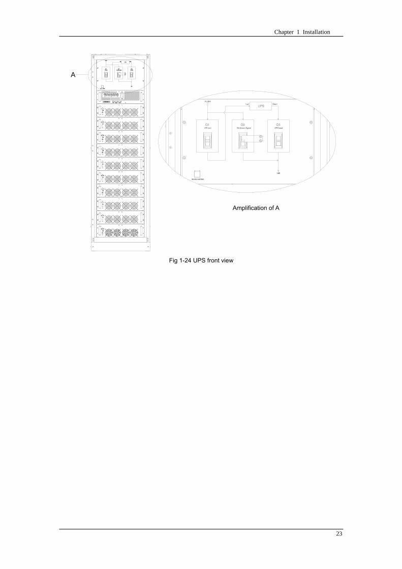
Chapter 1 Installation
23
A
A处放大
Fig 1-24 UPS front view
Amplification of A
24 Chapter 2 Operations
24
Chapter 2 Operations
This chapter introduces the basic knowledge of UPS operations including working principle
operation mode battery management and protection
Warning Hazardous mains voltage andor battery voltage present(s)behind the protective cover
The components that can only be accessed by opening the protective cover with tools cannot be
operated by user
Only qualified service personnel are authorized to remove such covers
21 Introduction
UPS provides the critical load (such as communication and data processing equipment) with high
quality uninterruptible AC power The power from UPS is free from voltage and frequency variations and
disturbances (interruption and spike) experienced at the Mains AC input supply
This is achieved through high frequency double conversion power pulse width modulation (PWM)
associated with full digital signal processing control (DSP) which features high reliability and
convenience for use
211 Principle
As shown in fig 2-1 the AC input mains source is supplied at UPS input and converted into a DC
source This DC source feeds the Inverter that converts the DC source into a clean and input
independent AC source The battery powers the load through the inverter in case of an AC input mains
power failure The utility source can also power the load through the static bypass
When the UPS needs maintenance or repair the load can be transferred to maintenance bypass
without interruption and the power module and bypass module can be removed for maintenance
Chapter 2 Operations 25
25
Fig 2-1 System principle framework
212 Bypass Module
The circuit blocks labeled ldquobypass modulerdquo in fig 2-1 contain electronically controlled switching
circuits that enable the critical load to be connected to either the inverter output or to a bypass power
source via the static bypass line During normal system operation the load is connected to the inverter
but in the event of a UPS overload or inverter failure the load is automatically transferred to the static
bypass line
To provide a clean (no-break) load transfer between the inverter output and static bypass line the
inverter output and bypass supply must be fully synchronized during normal operating conditions This is
achieved through the inverter control electronics which makes the inverter frequency track that of the
static bypass supply provided that the bypass remains within an acceptable frequency window
A manually controlled maintenance bypass supply is incorporated into the UPS design It enables
the critical load to be powered from the utility (bypass) supply while the UPS is shut down for routine
maintenance
Note
When the UPS is operating in bypass mode or on maintenance bypass the connected equipment is
not protected from power failures or surges and sags
22 Operation Mode
The MD UPS is an on-line double-conversion reverse-transfer UPS that permits operation in these
modes
Normal mode
26 Chapter 2 Operations
26
Battery mode
Auto-Restart mode
Bypass mode
Maintenance mode (manual bypass)
ECO mode
Frequency converters mode
221 Normal Mode
The UPS inverter power modules continuously supplies the critical AC load The rectifiercharger
derives power from the AC mains input source and supplies DC power to the inverter while
simultaneously FLOAT or BOOST charging its associated backup battery
222 Battery Mode
Upon failure of the AC mains input power the inverter power modules which obtains power from the
battery supplies the critical AC load There is no interruption in power to the critical load upon failure
After restoration of the AC mains input power the ldquoNormal Moderdquo operation will continue automatically
without the necessity of user intervention
Note UPS can also be started through battery (charged) mode via battery cold start function upon
failure of the AC mains Therefore the battery power can be used independently to improve the
utilization rate of UPS
223 Auto-Restart Mode
The battery may become exhausted following an extended AC mains failure The inverter shuts
down when the battery reaches the End of Discharge voltage (EOD) The UPS may be programmed to
ldquoAuto Recovery after EODrdquo after a delay time if the AC mains recovers This mode and any delay time
are programmed by the commissioning engineer
During the process of delay time the battery will be charged by UPS to prevent any risks to load
equipment from future mains failure
224 Bypass Mode
If the inverter overload capacity is exceeded under normal mode or if the inverter becomes
unavailable for any reason the static transfer switch will perform a transfer of the load from the inverter
to the bypass source with no interruption in power to the critical AC load
225 Maintenance Mode
A manual bypass switch is available to ensure continuity of supply to the critical load when the UPS
becomes unavailable eg during a maintenance procedure
Note This manual bypass switch is fitted in all UPS modules Transfer UPS system to bypass
module for power supply first then close maintenance bypass switch Q2 followed by Q1 and Q3
Warning hazard may occur after transferring to maintenance bypass
After UPS being transferred to maintenance bypass power module and bypass module do not work
no display on LCD and input and output terminals as well as N bus are electrically connected
Chapter 2 Operations 27
27
226 ECO Mode
If economical (ECO) mode is selected the double-conversion UPS will stop to work so as to save
energy During the operation of ECO mode the load power will be supplied by bypass preferentially
When bypass power is within the range of normal frequency and voltage load power will be supplied by
bypass or the system will transfer to inverter input followed by load power interruption which extends
within 34 of the utility period Eg when the frequency is 50Hz the interruption time will be less than
15ms when the frequency is 60Hz the time will be less than 125ms
227 Frequency Converters Mode
If the frequency converter configuration is used by UPS it will provide 50Hz or 60Hz stable output
frequency The range of output frequency is 40Hz~70Hz Under this mode static bypass is unavailable
but battery can be selected according to the actual requirements of battery mode
23 Battery Management
231 Normal Function
The following functions should be fitted by commissioning engineers with specified software
1 Constant current boost charging
Current can be set up
2 Constant voltage boost charging
Voltage of boost charging can be set as required by the type of battery
For Valve Regulated Lead Acid (VRLA) batteries maximum boost charge voltage should not
exceed 24V cell
3 Float charge
Voltage of float charging can be set as required by the type of battery
For VRLA float charge voltage should be between 22V to 23V
4 Float charge temperature compensation (optional)
A coefficient of temperature compensation can be set as required by the type of battery
5 End of discharge (EOD) protection
If the battery voltage is lower than the EOD the battery converter will shut down and the battery is
isolated to avoid further battery discharge EOD is adjustable from 16V to 175V per cell (VRLA) or 09
to 11 V per cell
6 Battery low warning time
It is adjustable between 3 and 60 minutes The default is 5 minutes
232 Advanced Functions (Battery Self-checking and Maintenance)
At periodic intervals 20 of the rated capacity of the battery will be discharged automatically and
the actual load must exceed 20 of the rated UPS (KVA) capacity If the load is less than 20
auto-discharge cannot be executed The periodic interval can be set from 30 to 360 days The battery
self-test can be disabled
ConditionsmdashBattery at float charge for at least 5 hours load equal to 20~100 of rated UPS capacity
TriggermdashManually through the command of ldquoBattery Maintenance Testrdquo in LCD panel or automatically
Battery Self-Test Intervalmdash30-360 days (default setting is battery self-test disabled)
28 Chapter 2 Operations
28
24 Battery Protection
The following functions should be fitted by commissioning engineers with specified software
1 Battery Low Pre-warning
The battery under voltage pre-warning occurs before the end of discharge After this pre-warning
the battery should have the capacity for 3 remaining minutes discharging with full load The time is user
configured from 3 to 60 minutes
2 Battery discharge (EOD)off protection
If the battery voltage is lower than the EOD the battery converter will be shut down EOD is
adjustable from 16V to 175V per cell (VRLA) or 09 to 11 V per cell (NiCd)
3 Battery Circuit Breaker (BCB) Alarm
The alarm occurs when the battery disconnect device disconnects The external battery connects to
the UPS through the external battery circuit breaker The circuit breaker is manually closed and tripped
by the UPS control circuit
Chapter 3 Operation Instructions 29
29
Chapter 3 Operating Steps
This chapter describes UPS operation instructions in detail
All functional keys and LED display involved in operation instructions please refer to chapter 4
During operation the buzzer alarm may occur at any time Select ldquomuterdquo on LED to muffle the audible
alarm
Warning-Hazardous mains voltage andor battery voltage present(s)behind the protective cover
1 The components that can only be accessed by opening the protective cover with tools cannot be
operated by user
2 Only qualified service personnel are authorized to remove such covers
31 Power Switches
As shown in fig 3-1 open the front door of UPS the power switch is visible which includes input
switch output switch and maintenance bypass switch (with anti-misoperation stop plate)
输入开关 输出开关
维修旁路开关
Fig 3-1 Power switch location diagram
32 UPS Start-up
The UPS system only has a maintenance bypass isolating switch and all the other transfers are
processed automatically by internal control logics
Input switch Output switch
Maintenance bypass switch
30 Chapter 3 Operating Instructions
30
321 Normal Module Start
This procedure must be followed when turning on the UPS from a fully powered down condition
The operating procedures are as follows
Warning
This procedure results in mains voltage being applied to the UPS output terminals If any load
equipment is connected to the UPS output terminals please check with the load user that it is safe to
apply power If the load is not ready to receive power then ensure that it is safely to close the output
switch of external distribution cabinet
1 Close UPS output switch and input switch in turns
The LCD starts up at this time The Rectifier indicator flashes during the startup of rectifier The
rectifier enters normal operation state and after about 30s the rectifier indicator goes steady green After
initialization the bypass static switch closes The UPS Mimic LEDs will indicate as shown in table 3-1
Table 3-1 Indicator status
LED Status
Rectifier indicator Green
Battery indicator Red
Bypass indicator Green
Inverter indicator Off
Load indicator Green
Status indicator Green
Note
The output circuit breaker must be closed first followed by input circuit breaker or the rectifier cannot
be started and alarm ldquorectifier failurerdquo
The inverter starts up at this time the inverter indicator flashes After the rectifier enters normal
operation state UPS power supply will transfer from bypass to inverter then the bypass indicator turns
off and load indicator lights The status of indicators is shown in table 3-2
Table 3-2 Indicator Status
LED Status
Rectifier indicator Green
Battery indicator Red
Bypass indicator Off
Inverter indicator Green
Load indicator Green
Status indicator Green
Close external battery switch again battery indicator turns off a few minutes later the battery will be
charged by UPS which will enter normal mode operation The indicator status is shown in table 3-3
Table 3-3 Indicator status
LED Status
Rectifier indicator Green
Battery indicator Green
Bypass indicator Off
Inverter indicator Green
Load indicator Green
Status indicator Green
322 Operating steps of Battery cold Start
1 Check if the batteries have been connected close the external battery switch
Chapter 3 Operation Instructions 31
31
2 Press the red start-up button of battery under the rectifier input circuit breaker for 3 seconds (see fig
3-2)
The LCD starts up at this time The green battery indicator flashes The rectifier enters normal
operation states and after about 30s the battery indicator goes steady green
3 The inverter starts up automatically the green inverter indicator flashes The output of inverter
appears after 60s The UPS works on battery mode
32 Chapter 3 Operating Instructions
32
电池启动按钮
Fig 3-2 Position diagram of battery startup button
Battery startup button
Chapter 3 Operation Instructions 33
33
33 Procedure for Switching between Operation Modes
331 Procedure for Switching the UPS into Battery mode from Normal Mode
Open input switch to cut off the mains UPS enters the battery mode If UPS should be switched to
normal mode wait for a few seconds before close input switch so as to supply the mains again 10s
later the rectifier will start up automatically to supply power to the inverter
332 Procedure for Switching the UPS into Bypass mode from Normal Mode
Select ldquoTran Byprdquo on the LCD or press ldquooffrdquo buttons of each power module in turn
Note
In bypass mode the load is directly fed by the mains power instead of the pure AC power from the
inverter
333 Procedure for Switching the UPS into Normal from Bypass Mode
Select exit bypass mode on the LCD
334 Procedure for Switching the UPS into a Maintenance Bypass from Normal Mode
In normal operation this operation instruction will switch the load from inverter input to maintenance
bypass
Caution
Before making this operation read messages on display to be sure that bypass supply is regular and
the inverter is synchronous with it so as not to have a risk of a short interruption in powering the load
1 Press ldquoTran Byprdquo on the LCD or press ldquooffrdquo on each power module in turns
If press rdquoTran Byprdquo on the LCD the inverter indicator will flash green and the buzzer will alarm
If press ldquooffrdquo on each power module in turns the inverter indicator will go off and the buzzer will
alarm
The load will be transferred to static bypass and the inverter is closed
2 Close maintenance bypass switch Q2 the load power will be supplied by maintenance bypass and
then open the inverter circuit breaker Q1 output switch Q3 and battery switch
Warning
If you need to maintain the module wait for 10 minutes to let the DC bus capacitor fully discharge
before removing corresponding module
335 Procedure for Switching the UPS into Normal from a Maintenance Bypass Mode
This procedure can transfer the load to normal main mode when the UPS is operating under the
maintenance bypass mode
1 Close output switch Q3 and main switch Q1
The bypass indicator goes green and the load power will be supplied by bypass and maintenance
bypass
2 Open maintenance bypass switch Q2
34 Chapter 3 Operating Instructions
34
The load power is supplied by bypass In the meantime the rectifier starts up rectifier indicator goes
green 30s later at this time the inverter will start up automatically and transfer to inverter mode 1 min
later automatically
3 Close external battery switch the battery indicator goes off Check if the battery voltage on LCD
display is normal
34 Procedure for Completely Powering down a UPS
If you need to power down the UPS completely follow the procedures in section 334 to transfer the
UPS from normal mode to maintenance bypass mode
If you need to isolate the UPS from the AC power supply you should open the external input switch
35 EPO Procedure
The EPO button on UPS operator control and display panel is designed to switch off the UPS in
emergency conditions (eg fire flood etc)To achieve this just press the EPO button and the system
will turn off the rectifier inverter and stop powering the load immediately (including the inverter and
bypass output) and the battery stops charging or discharging
If the input utility is present the UPS control circuit will remain active however the output will be
turned off To completely isolate the UPS you need to open the external mains input supply to the UPS
rack
36 Language Selection
The LCD is available in two languages Chinese English and Korean
The language can be selected through LCD prompt window
37 Control Password
When the LCD displays ldquoinput control password 1rdquo the initial password is 12345678
Chapter 4 Operator Control and Display Panel 35
35
Chapter 4 Operator Control and Display Panel
This chapter introduces the functions and operation instructions of the parts on UPS operator control
and display panel in detail and provides LCD display information including LCD display types detailed
menu information prompt window information and UPS alarm list
41 Introduction
The operator control and display panel is located on the front panel of the UPS Through this LCD
panel the operator can operate and control the UPS and check all measured parameters UPS and
battery status and event and alarm logs The operator control panel is divided into three functional areas
as shown in fig 4-1 mimic current path LCD display amp Menu keys and Control and Operation Keys The
detailed description of parts on operator control and display panel is shown in table 4-1
Fig 4-1 UPS operator control and display panel
Table 4-1 Description of UPS operator control and display panel
Part No Function Button Function
REC Rectifier indicator EPO EPO switch
BAT Battery indicator TAB switch
BYP Bypass indicator ENTER confirm
INV Inverter indicator ESC exit
OUTPUT Load indicator
STATUS Status indicator
36 Chapter 4 Operator Control and Display Panel
36
411 LED Indicator
The LEDs shown on the mini current path represent the various UPS power paths and show the
current UPS operating status The status description of indicators is shown in table 4-2
Table 4-2 Status description of indicator
Indicator State Purpose
Rectifier
indicator
Steady green Rectifier normal for all modules
Flashing green Rectifier for at least on module normal mains normal
Steady red Rectifier fault
Flashing red Mains abnormal for at least one module
Off Rectifier not operating
Battery
indicator
Steady green Battery charging
Flashing green Battery discharging
Steady red
Battery abnormal (battery failure no battery or battery reverse) or
battery converter abnormal (failure over current or over temperature)
EOD
Flashing red Battery low voltage
Off Battery and battery converter normal battery not charging
Bypass
indicator
Steady green Load power supplied by bypass
Steady red Bypass power abnormal or out of normal range or static bypass
switch fault
Flashing red Bypass voltage abnormal
Off Bypass normal
Inverter
indicator
Steady green Load power supplied by inverter
Flashing green Inverter On start synchronization of standby (ECO mode) for at least
one module
Steady red System power not supplied by inverter inverter fault for at least one
module
Flashing red System power supplied by inverter inverter fault for at least one
module
Off Inverter not operating for all modules
Load
indicator
Steady green UPS output ON and normal
Steady red UPS output overload and overtime or output short or output no power
supply
Flashing red Overload output of UPS
Off No output of UPS
Status
indicator
Steady green Normal operation
Steady red Failure
412 Audible Alarm (buzzer)
There are two different types of audible alarm during UPS operation as shown in table 4-3
Table 4-3 description of audible alarm
Alarm Purpose
Two short alarm with
a long one
when system has general alarm (for example AC fault) this audible alarm
can be heard
Continuous alarm When system has serious faults (for example fuse or hardware fault) this
audible alarm can be heard
Chapter 4 Operator Control and Display Panel 37
37
413 Functional Keys
There are 4 functional keys on operator control and display panel which are used together with LCD
The functions description is shown in table 4-4
Table 4-4 Functions of functional keys
Functional key Functions
EPO switch To cut off the load power to shut down the rectifier inverter static
bypass and battery
TAB switch
ENTER confirm
ESC exit
42 LCD Display Type
Following the self-check of UPS LCD display the main LCD display is shown as fig 4-2 which can
be divided into three display windows system information data command and current record
Fig 4-2 Main LCD display
The description of LCD icon is shown in table 4-5
Table 4-5 Description of LCD icons
Icon Description
Bypass parameter
UPS system
information
window
Data
command
window
Current
record
window
38 Chapter 4 Operator Control and Display Panel
38
Icon Description
Main input parameter
History file system information
Function setting (display calibration password setting time setting date format
communication protocol and language setting) system setting (used by product
maintainers)
Battery data battery parameter setting (used by service staff)
Test (battery self-test battery maintenance)
Functional keys used by service staff (fault clearing history file clearing noise
clearing manual switch of bypass) userrsquos setting (system mode machine
number system ID output voltage adjustment frequency tracing speed
frequency tracing limit)
Output parameter
Load
Noise clearing noise clearing cancel
Log view page updown
Select a icon on LCD as shown in fig 4-3 to view the UPS parameter represented by this icon eg
select the LCD will display the data of system main input
Chapter 4 Operator Control and Display Panel 39
39
Fig 4-3 Select data
Or select and confirm a module as shown in fig 4-4 the LCD will display the
operating status of this module
Fig 4-4 Select a module
40 Chapter 4 Operator Control and Display Panel
40
Select in the operating status of a module to view the main input data of this module
Select in the operating status of a module to view the main output data of this module
Select in the operating status of a module to view the load data of this module
Select in the operating status of a module to view the maintenance code and module
software code of this module
Select to return to the previous page
Select to return to the home page
Default display
During the operation of system if therersquos no alarm in 2 min the system will display default After a
short delay the backlight of LCD display goes off press any key to reactivate the display
43 Detailed Description of Menu Items
The LCD main display shown in fig 4-2 is described in details below
UPS information window
UPS information window display the current time and UPS name The information of the window is
not necessary for the user to operate The information of this window is given in table 4-6
Table 4-6 Description of items in UPS system information window
Display contents Meaning
MD12020 UPS Name
1200 Current Time (format 24 hours hours minute)
UPS menu and data window
UPS menu window displays the menu name of data window while the data window displays the
related contents of selected menu in menu window Select UPS menu and data window to browse
related parameters of UPS and set related functions The details are given in table 4-7
Table 4-7 Item description of UPS menu and data window
Menu name Menu item Meaning
Main input
V phase(V) V phase
I phase(A) I phase
Freq(Hz) Input frequency
PF Power factor
Bypass input
V phase(V) V phase
Freq (Hz) Bypass frequency
I phase(A) I phase
PF Power factor
AC output
V phase(V) V phase
I phase(A) I phase
Freq (Hz) Output frequency
PF Power factor
This UPS Sout (kVA) Sout Apparent Power
Chapter 4 Operator Control and Display Panel 41
41
Menu name Menu item Meaning
modulersquos
load
Pout (kW) Pout Active Power
Qout (kVAR) Qout Reactive Power
Load () Load (The percentage of the UPS rating load)
Battery data
Environmental
Temp Environmental Temp
Battery
voltage(V) Battery bus voltage
Battery current
A) Battery bus current
Battery
Temp() Battery Temp
Remaining Time
(Min) Remaining battery backup time
Battery capacity
() The percentage compared with new battery capacity
battery
equalized
charging
Battery is equalized charging
battery float
charging Battery is float charging
Battery
disconnected Battery is not connected
Current
record (current alarm)
Display all current alarm The alarm list displayed on LCD of
UPS operator control and display panel please refer to table 4-9
History
record (history alarm)
Display all history alarm The alarm list displayed on LCD of
UPS operator control and display panel please refer to table 4-9
Menu
Language
(language
option) 2 languages can be selected
Settings
Display
calibration Adjust the accuracy of LCD display
Date format set MM DD YYYY and YYYY MM DD formats can be selected
Date amp Time DateTime set
Language set User can set the language (Chinese and English)
Communication
mode
Set communication mode MODBUS Power protocol and
company custom protocol modes can be selected Power
protocol mode can be divided into equipment address baud
rate set MODBUS protocol mode can be divided into
communication mode (RTUASCⅡ) equipment address
baud rate and check-bit set Company custom protocol mode
is the customed protocol of the company no option is
available
Control
password set User can modify control password 1
Test
Command
(Battery Test
Control
Battery
maintenance
test
This test will lead to the battery being partly discharged to
activate battery at the same time the approximate battery
capacity will be obtained Bypass must be in normal condition
the battery capacity should be above 25
42 Chapter 4 Operator Control and Display Panel
42
Menu name Menu item Meaning
Battery
self-check test
UPS switches to battery discharge for discharging to test if the
battery is normal Bypass must be in normal condition the
battery capacity should be above 25
Stop testing Manually Stop the test including maintenance test capacity test
UPS system
information
Monitoring
software version Provide monitoring software version
Rectified
software version Provide rectified software version
Inverted
software version Provide inverted software version
Serial No The serial no set when delivery from the factory
Rated
information Network setting of system operating
Module type Type of the module
44 Alarm List
The follow table 4-8 gives the complete list of all the UPS events displayed by history record window
and current record window
Table 4-8 Alarm List
Alarm Explanation
UPS power supply The system is in normal inverted power supply status
Bypass power
supply The system is in bypass power supply status
No power supply System no output
Battery equalized
charging Battery is in boost charging
Battery float
charging Battery is in float charging
Battery discharging The system is operating in battery discharging status
Battery connected Battery is connected
Battery
disconnected Battery is not connected
Maintenance circuit
breaker close Maintenance circuit breaker is close
Maintenance circuit
breaker open Maintenance circuit breaker is open
Emergency
shutdown System emergency shutdownEPO
Generator
connected External generator is connected
Mains abnormal Input mains abnormal
Bypass phase
conversion Bypass input phase converse
Bypass voltage
abnormal Bypass input voltage abnormal
Bypass fault Bypass fault
Bypass overload Bypass output is overload
Up to bypass
overtime of Bypass is overtime of overload
Chapter 4 Operator Control and Display Panel 43
43
Alarm Explanation
overload
Bypass frequency
tracing exceeds Bypass frequency is out of the tracing range
Switch times up to
in this hour
The times of switch between bypass and inverter exceeds 5 times in the latest
hour
Output short System output short
Battery EOD Battery voltage achieves shutdown point
Battery self-check The system enters battery self-check mode
Battery self-check
success Battery normal during system self-check
Battery manual
check failure Battery fault during system self-check
Battery
maintenance The system is in battery maintenance status
Battery
maintenance
success
Battery maintenance status completes
Battery
maintenance failure Battery maintenance process is not normal
Stop testing Battery self-check or battery maintenance status stops
Fault clearing Clear the alarmed fault
Delete history
record Delete all history record
N communication
node connected N module is connected to UPS system
N communication
node disconnected N module is not connected to UPS system
N rectifier fault N module rectifier fault
N inverter fault N module inverter fault
N rectifier
overheat N module rectifier overheat
N fan fault N module fan fault
N output overload N module output overload
N overtime of
overload N module output overtime of overload
N inverter
overheat N module inverter overheat
Inverter power
supply ban Inverter power ban supply
Manual switch of
bypass Switch the system to bypass output manually
Cancel manual
switch of bypass Switch the system from bypass to inverter output manually
Battery low voltage Battery low voltage
Battery reversal Battery polarity reversal
N inverter
protection N module inverter protection
Input N line
disconnected System input N line is not connected
Bypass fan fault Bypass module fan fault
N manual N module manual power off
44 Chapter 4 Operator Control and Display Panel
44
Alarm Explanation
shutdown
Chapter 5 Maintenance 45
45
Chapter 5 Installation of Parallel Operation System
The parallel operation system is installed as required by the installation procedures of the single
system and this chapter
The single devices are put parallel and connected as shown in fig 5-1 and the difference between
the lengths of the output cables of the single devices is not more than 10m It is recommended to use an
external bypass cabinet to facilitate maintenance and system testing
Fig 5-1 Typical 1+N parallel operation system
Note when the load exceeds is the capacity of the single device the maintenance bypass
switch CB3 must be removed
The cables for the parallel operation provide double insulation shielding up to 30m long the control
cables for the parallel operation must be connected with all single devices to form a closed loop as
shown in fig5-2
Other power supplies
Rectifier
Charger Inverter Inverter
Output power supply
Load connected
Mains power input L1 L2 L3 N terminal
Mains power inputL1 L2 L3 N terminal
Rectifier
Charger
46 Chapter 5 Maintenance
46
Fig5-2 parallel cables
Chapter 5 Maintenance 47
47
Chapter 6 Maintenance
This chapter introduces UPS maintenance including the maintenance instructions of power module
monitoring bypass module and the change method of dust filter
61 Instruction to Power Bypass and Output Power Distribution
Module
611 Precautions
1 Only maintaining engineers can maintain the power module and monitoring bypass module
2 In principle the power module and bypass module should be disassembled from top to bottom so
as to prevent any inclination from high gravity centre of the cabinet
3 To ensure the safety before maintaining power module and bypass module be sure to use a
multimeter to measure the DC bus capacitor voltage and ensure the voltage is below 60V before
operation and use a multimeter to measure the voltage between operating parts and the earth to
ensure the voltage is lower than hazardous voltage ie DC voltage is lower than 60Vdc and AC
maximum Voltage is lower than 424Vac
4 Bypass module doesnrsquot support any hot insertion and extraction only when UPS is in maintenance
bypass mode or UPS is completely power off can the bypass module be disassembled
5 The module can be maintained 10 mins after extracting power module and bypass module which
can be inserted into the cabinet 10 mins later
612 Instruction to Power Module
Suppose UPS were in normal mode and bypass were normal a module shall be maintained at
first
1 Press OFF of the module with a pin point or other tiny matter the module will shut down
automatically and exit the system
Note ensure if the remaining module will be overload when exiting a module If therersquos any risk of
overload transfer the whole UPS system to bypass followed by other operations
2 Take off the fixing bolt on the two sides of front and back plate of power module 10 mins later
extract the module from the cabinet
3 After maintaining the module push the module into the equipment cabinet (the interval between
two modules shall be more than 10s) fix the screw on the two sides Then the module will be
connected to UPS system automatically
613 Instruction to Bypass Module
Suppose UPS were in normal mode and the bypass were normal
1 Select LCD touch screen manual switch of bypass the UPS power will be supplied by bypass
2 Close maintenance bypass switch the UPS power will be supplied by maintenance bypass
3 Open UPS output switch and input switch
4 Open external battery switch
48 Chapter 5 Maintenance
48
5 Take off the fixing bolt at the two sides of front board of bypass module extract the front cable
assembly of the module and extract the module from the cabinet
6 After maintaining the module insert the module into the cabinet tighten the screw at the two sides
and connect the front cable assembly of manufacturerrsquos module
7 Close UPS output switch and input switch in turn
2 mins later bypass indicator on the operator control and display panel lights on which indicates
the normal power supply of bypass
8 Open maintenance bypass switch the inverter starts automatically 60s later the UPS will transfer
to normal mode
62 Replacing Dust Screen (optional)
As shown in fig 5-1 there are 3~4 dust filters on the back of UPSrsquo front door each screen is held in
place by a bracket on either side of each filter The procedure of replacing each filter is as follows
1 Open the UPSrsquo front door and locate the filters on the back side of the front door
2 Remove one bracket
3 Remove the dust screen to be replaced and insert the clean one
4 Reinstall the bracket
防尘网固定条
Fig 5-1 Dust screen on the back side of UPS front door
Bracket
Dust screen
Appendix 2 Toxic or Hazardous Materials or Elements Identification Table 49
49
Chapter 7 Product Specification
This chapter provides UPS product specification
71 Applicable Standards
The UPS has been designed to conform to the following European and international standards
Table 6-1 Compliance with European and International Standards
Item Normative reference
General safety requirements for UPS
used in operator access areas EN50091-1-1IEC62040-1-1AS 62040-1-1
Electromagnetic compatibility (EMC)
requirements for UPS EN50091-2IEC62040-2AS 62040-2(C3)
Method of specifying the performance
and test requirements of UPS EN50091-3IEC62040-3AS 62040-3(VFI SS 111)
Note The above mentioned product standards incorporate relevant compliance clauses with generic
IEC and EN standards for safety (IECENAS60950) electromagnetic emission and immunity
(IECEN AS61000 series) and construction (IECENAS60146 series and 60950)
72 Environmental Characteristics
Table 6-2 Environmental Properties
Items Unit Requirements
Acoustic noise level at 1
meter dB 550
Altitude of Operation m le1000m above sea level derate power by 1 per 100m
between 1000m and 2000m
Relative Humidity RH 0 to 95 non condensing
Operating Temperature 0 to 40 deg Battery life is halved for every 10degC increase
above 20degC
UPS Storage-Transport
Temperature -20~70
Recommended Battery
Storage Temperature -20~30 (20degC for optimum battery storage)
73 Mechanical Characteristics
Table 6-3 Mechanical Properties
Cabinet Specification Unit MD6010 MD9015
MD12020
MD10010 MD15015
MD20020
Mechanical Dimension
WtimesDtimesH mm 600times900times1600 600times900times2000
Weight kg 151 182
Color NA Black
Protection Level
IEC(60529) NA IP20
50 Chapter 5 Maintenance
50
Module type Unit MU10 MU15 MU20
Mechanical Dimension
WtimesDtimesH mm 440times590times134
Weight kg 21 22 22
Color NA Black
74 Electrical Characteristics (Input Rectifier)
Table 6-4 Rectifier AC input (mains)
Items Unit Parameter
Rated AC Input
Voltage Vac
380400415(three-phase and sharing neutral with the
bypass input)
Input voltage range Vac -40~+25
Frequency2 Hz 5060(range 40Hz~70Hz)
Power factor kWkVA full load 099
THD THDI 3
75 Electrical Characteristics (Intermediate DC Link)
Table 6-5 Battery
Items Unit Parameters
Battery bus
voltage Vdc Nominal plusmn240V one-side range 198V~288V
Quantity of
lead-acid cells Nominal 40=[1 battery(12V) ] 240=[1 battery(2V) ]
Float charge
voltage Vcell(VRLA)
225Vcell(selectable from 22Vcell~235Vcell)
Constant current and constant voltage charge mode
Temperature
compensation mVcl -30(selectable from 0~-50 25 or 30 or inhibit)
Ripple voltage V float le1
Ripple current C10 le5
equalized
charge voltage VRLA
24Vcell(selectable from 230Vcell~245Vcell)
Constant current and constant voltage charge mode
final
discharging
voltage
Vcell(VRLA)
165Vcell(selectable from 160Vcell ~ 1750Vcell) 06C
discharge current
175Vcell (selectable from 165Vcell ~ 18Vcell) 015C
discharge current
(EOD voltage changes linearly within the set range according to
discharge current)
Battery Charge Vcell 24Vcell(selectable from 23Vcell~245Vcell)
Constant current and constant voltage charge mode
Battery
Charging Power
Max Current
kW 10 UPS capacity (selectable from 0~20 UPS capacity)
Appendix 2 Toxic or Hazardous Materials or Elements Identification Table 51
51
76 Electrical Characteristics (Inverter Output)
Table 6-6 Inverter Output (to important load)
Rated
capacity(kVA) Unit 10~200
Rated AC voltage1 Vac 380400415(three-phase four-wire and sharing neutral with the
bypass)
Freqency2 Hz 5060
overload
110 load 1 hour
125 load 10min
150 load 1min
>150 load 200ms
Fault current 340 short current limitation for 200ms
Non linear load
capability 3 100
Neutral current
capability 170
Steady state
voltage stability
plusmn1(balanced load)
plusmn15(100 imbalance load)
Transient voltage
response 4 plusmn5
THD <15(linear load) <5(non linear load3)
Synchronization -
Window Rated frequency plusmn2Hz(selectable plusmn1~plusmn5Hz)
Max change rate of
synch frequency Hzs 1 selectable 01~5
Inverter voltage
range V(ac) plusmn5
Note
1 Factory setting is 380V Commissioning engineers can set to 400V or 415V
2 Factory setting is 50Hz Commissioning engineers can set to 60Hz
3 EN50091-3(1458) peak value factor is 3 1
4 IEC62040-3EN50091-3 including 0~100~0 load transient the recovery time is half
circle to within 5 of stable output voltage
52 Chapter 5 Maintenance
52
77 Electrical Characteristics(Bypass Mains Input)
Table 6-7 Bypass Mains Input
Rated
capacity(kVA) Unit 60 90 100 120 150 200
Rated AC
Voltage1 Vac
380400415
three-phase four-wire sharing neutral with the rectifier input and providing neutral
reference for the output
Rated current A
91380V
87400V
83415V
136380V
130400V
124415V
151380V
144400V
138415V
182380V
174400V
166415V
227380V
216400V
207415V
302380V
288400V
276415V
Overload
125 load long term
130 load 1 hour
150 load 6min
1000 load 100ms
Superior
protection
bypass line
NA Thermal-magnetic breaker the capacity is 125 of rated current output
IEC60947-2 curve C
Current rating
of neutral cable A 17timesIn
Frequency2 Hz 5060
Switch time
(between
bypass and
inverter)
ms Synchronized switch le1ms
Bypass voltage
tolerance Vac
Upper limit +10+15or+20 default +20
Lower limit -10 -20 -30 or-40 default-20
(acceptable stable bypass voltage delay 10s)
Bypass
frequency
tolerance
plusmn25 plusmn5 plusmn10 or plusmn20 default plusmn10
Synchronizatio
n-Window Hz Rated frequencyplusmn2Hz (selectable from plusmn05Hz~plusmn5Hz)
Note
1 Factory setting is 400V Commissioning engineers can set to 380V or 415V
2 Factory setting is 50Hz Commissioning engineers can set to 60Hz For example UPS is set to frequency
inverter mode and then bypass status will be neglected
78 Efficiency
Table 6-8 Efficiency Loss and Air Exchange
Rated Efficiency (kVA) Unit 10~200kVA
Normal mode(dual conversion) 95
ECO mode 99
Battery discharging efficiency (DCAC) (battery at nominal voltage 480Vdc and full-rated linear load)
battery mode 95
Appendix 2 Toxic or Hazardous Materials or Elements Identification Table 53
53
Appendix A A Guidebook to Ordering and Selection of MU System
MD series UPS module can be divided into equipment cabinet and power module For the cabinet
lectotype please refer to the description in fig 6-1
Fig 6-1 Cabinet Selection
For single power module type please refers to the description in fig 6-2
Fig 6-2 Power Module Selection
Egg the requirements of a plant room are given below
The maximum power supply of the plant room is 120kVA however it is expected to be expanded to
200kVA in 3-5 years Therefore a 200kVA cabinet and 6 20kVA power module can be purchased to
constitute an uninterrupted 120kVA power system which can be expanded to 200kVA on-line The order
symbol is
1 set MD20020
6 set MU20
Option list
MD-SNMP card remote network monitoring card
MD-1600 dust filter dust screen for 16m cabinet
MD-2000 dust filter dust screen for 2m cabinet
Represents the capacity of a single power module
10 represents 10kVA
15 represents 15kVA
20 represents 20kVA
represents a single power module
Represents UPS system capacitypower module
06010 represents 60kVA10kVA
09015 represents 90kVA15kVA
12020 represents 120kVA20kVA
15015 represents 150kVA15kVA
20020 represents 200kVA20kVA
MD represents UPS cabinet
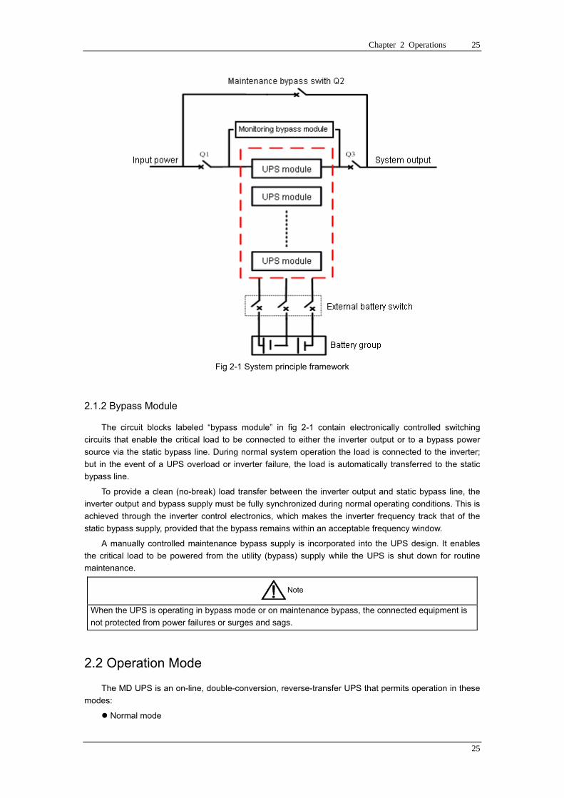
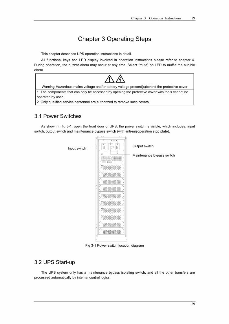
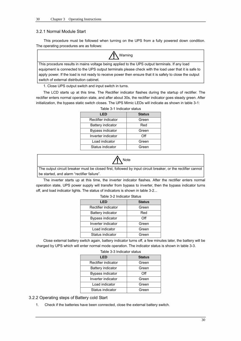
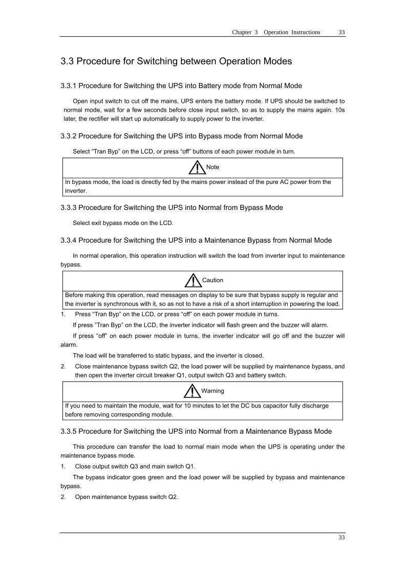
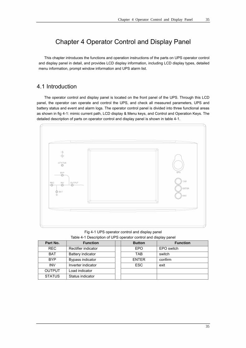
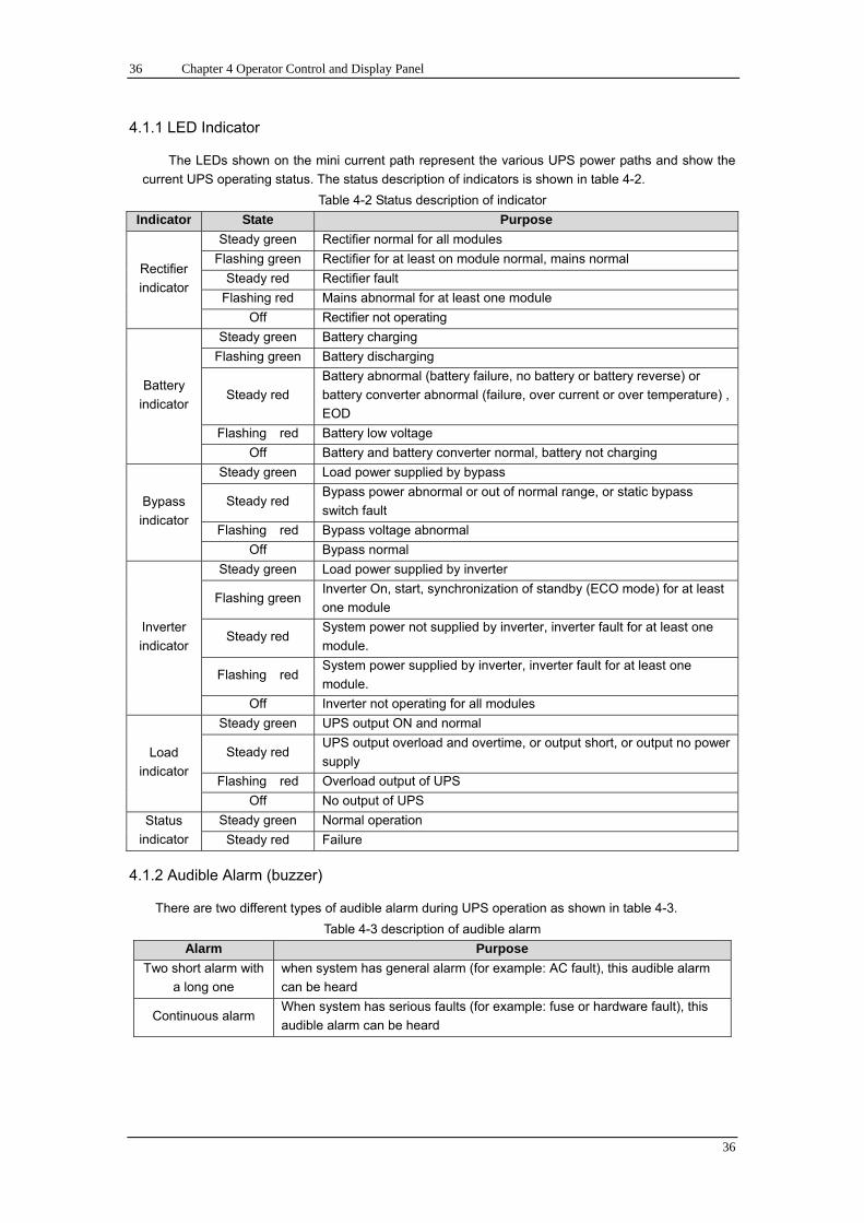
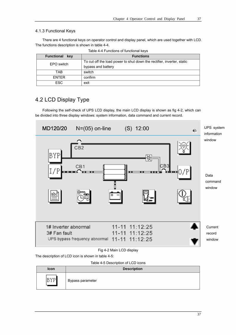
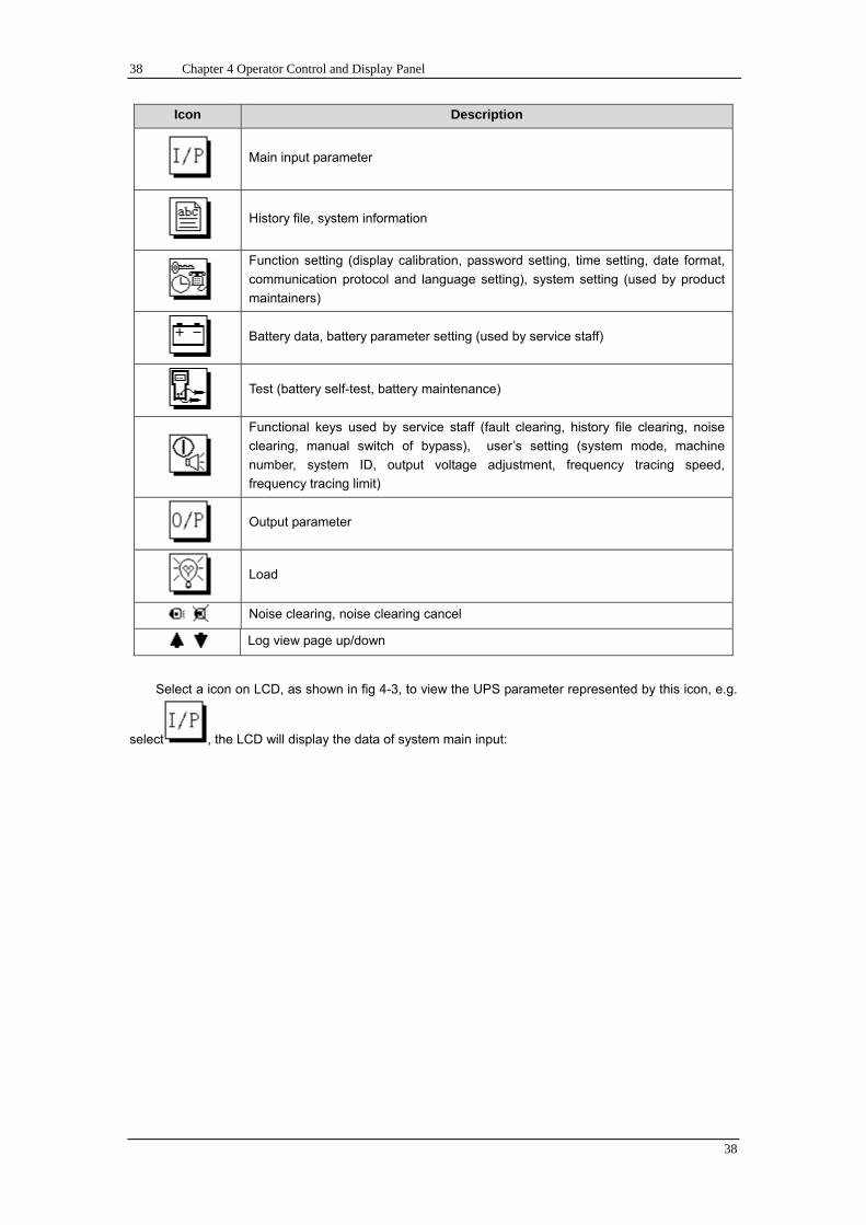
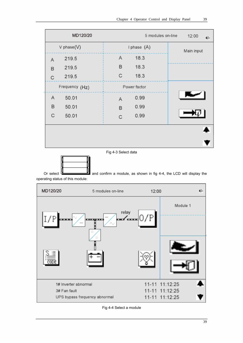
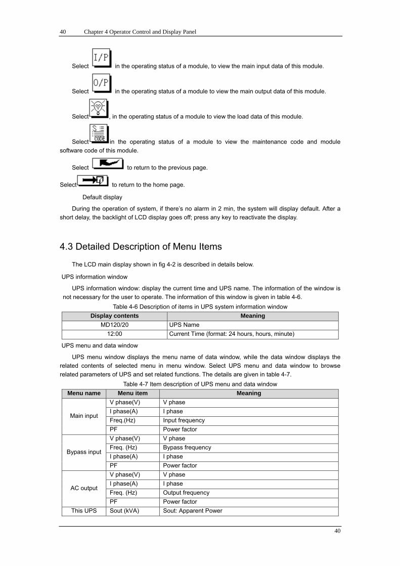
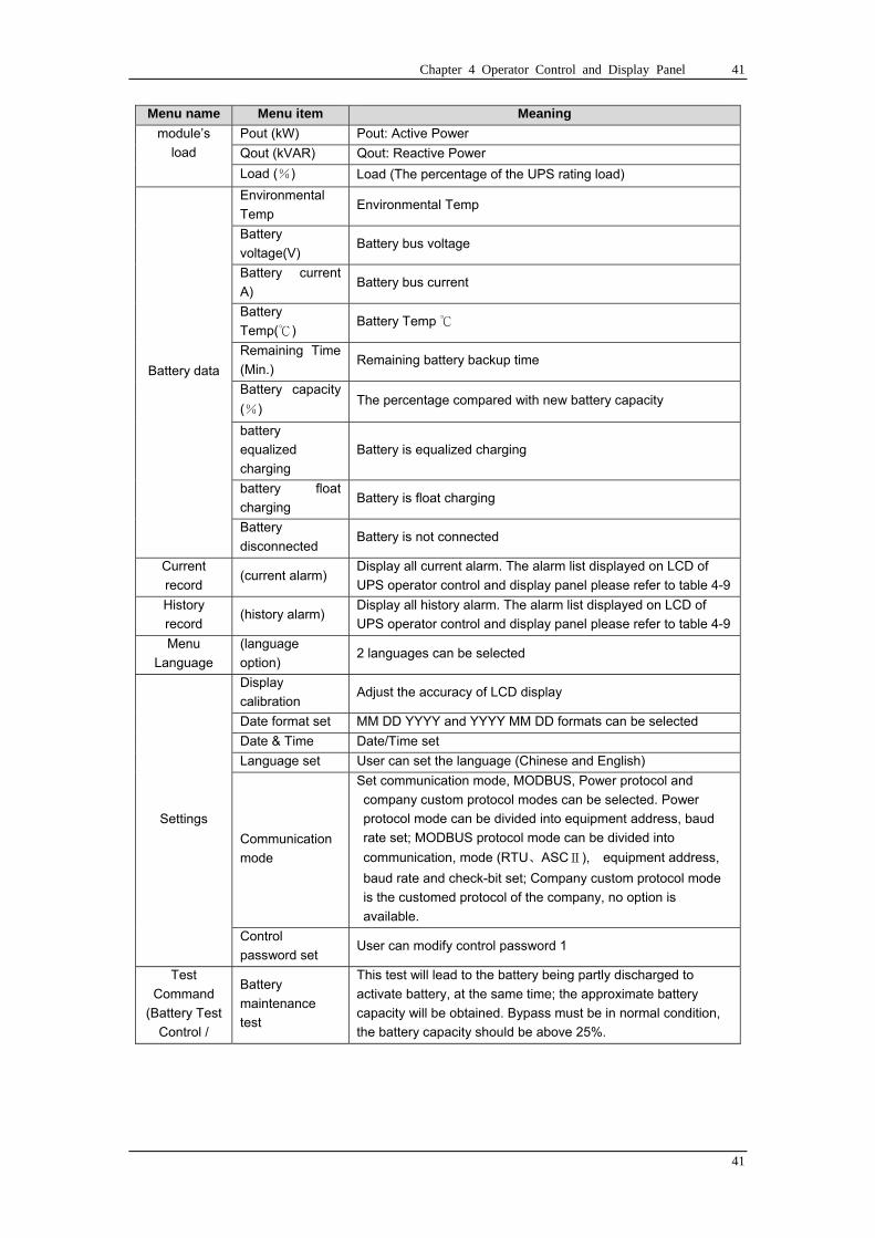
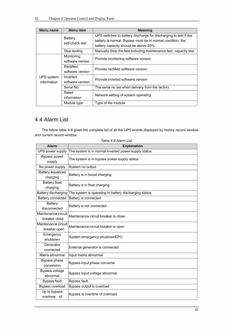
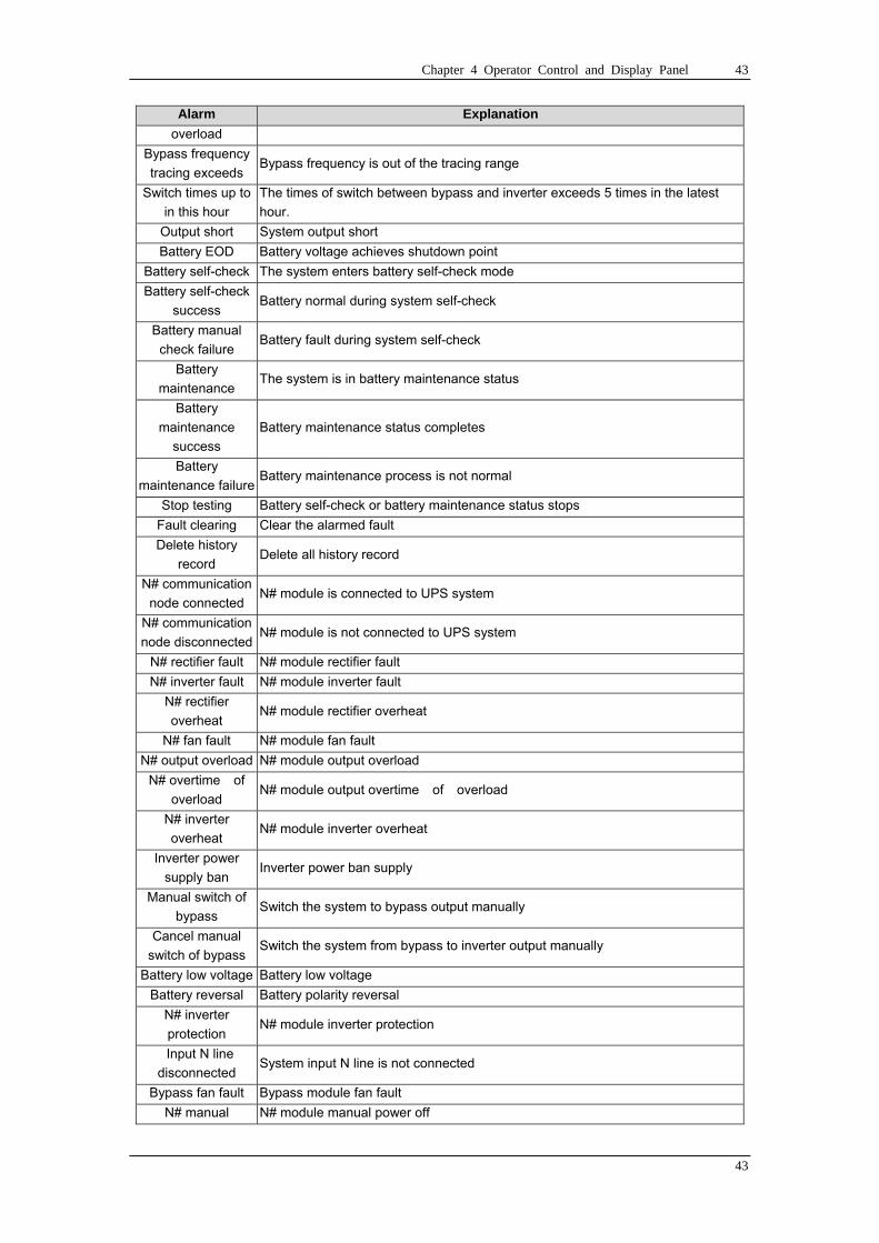
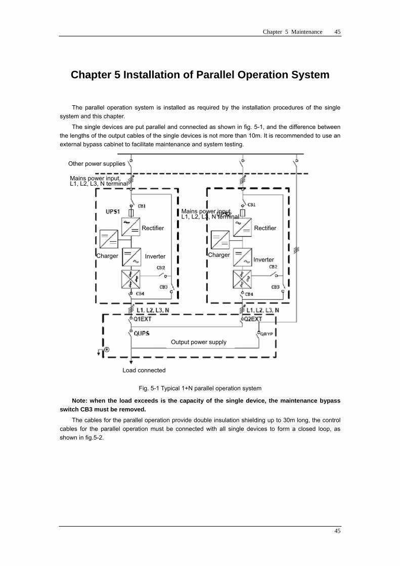
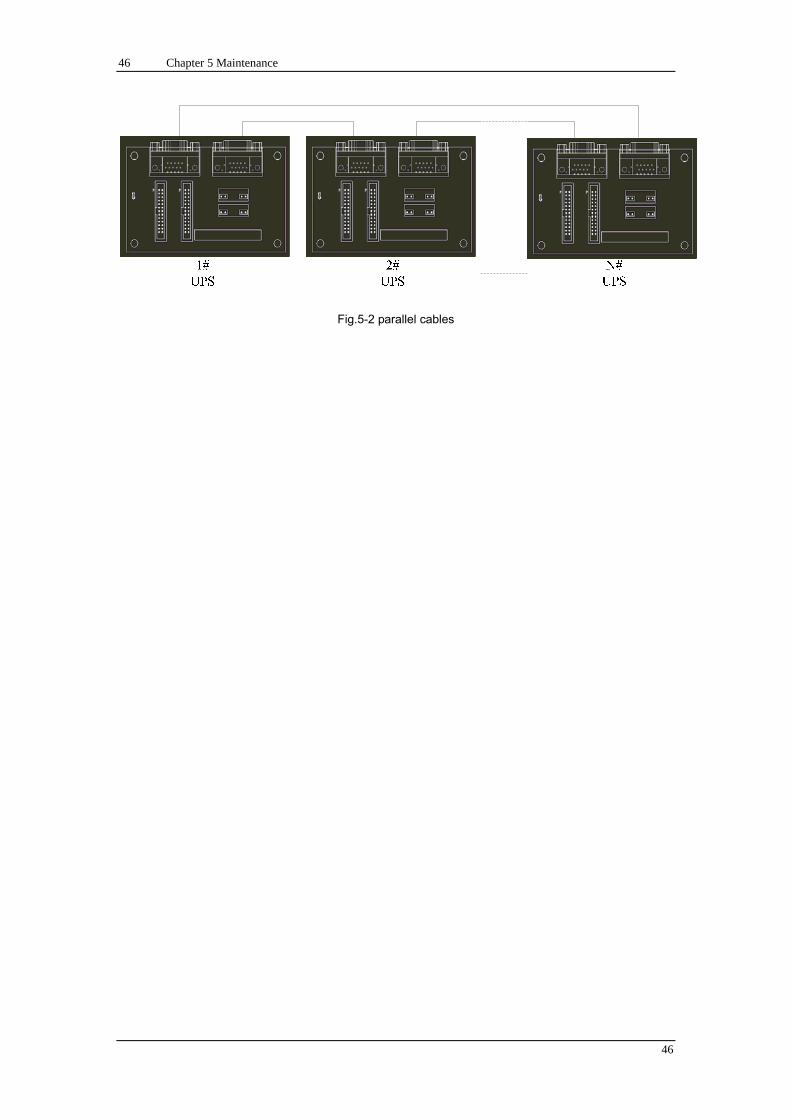
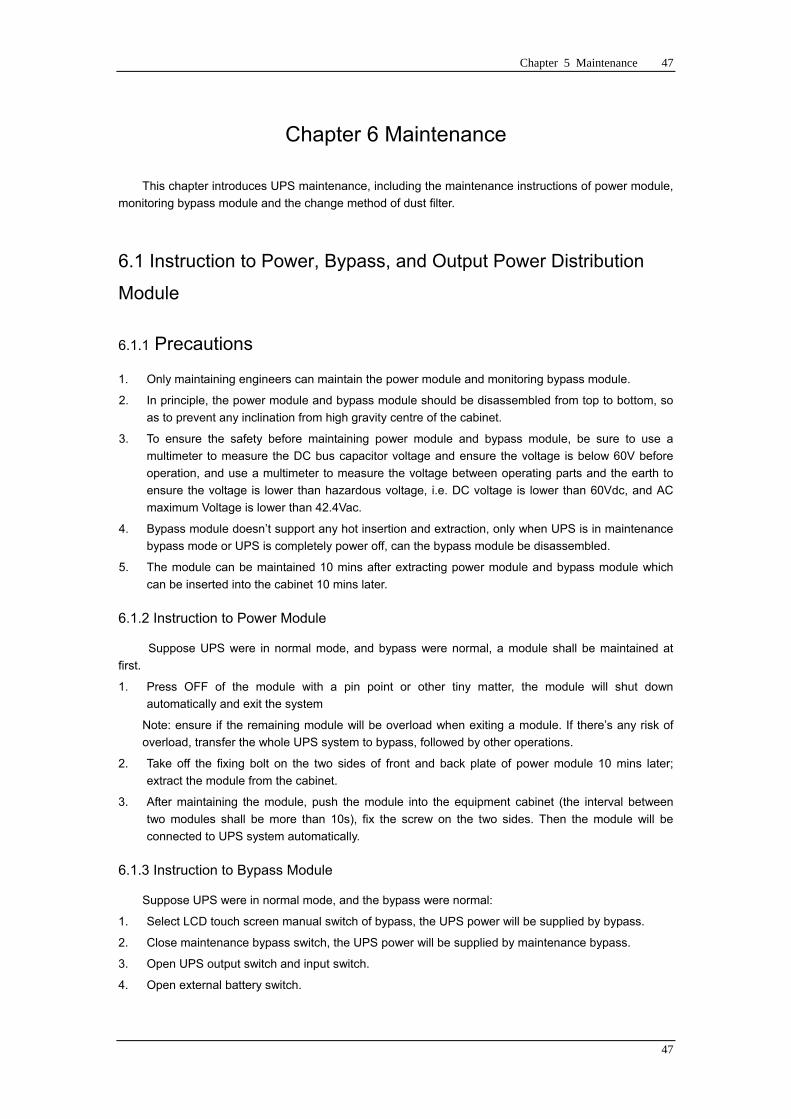
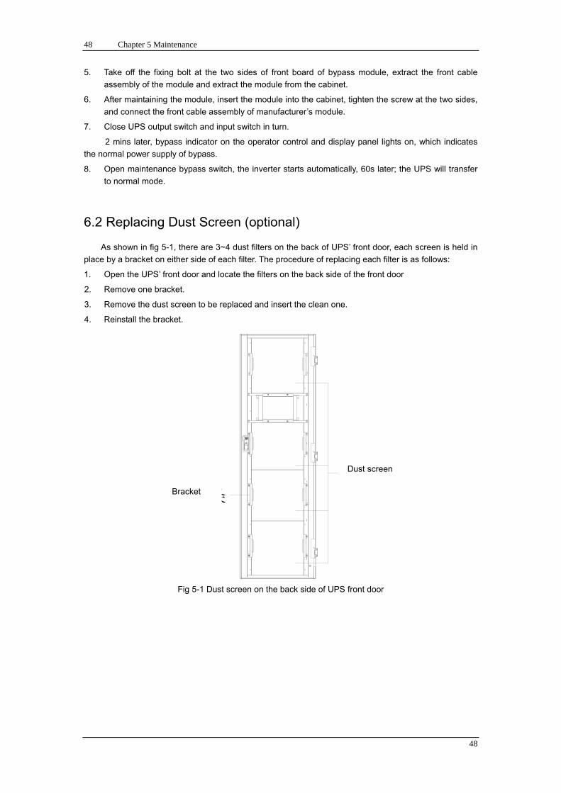
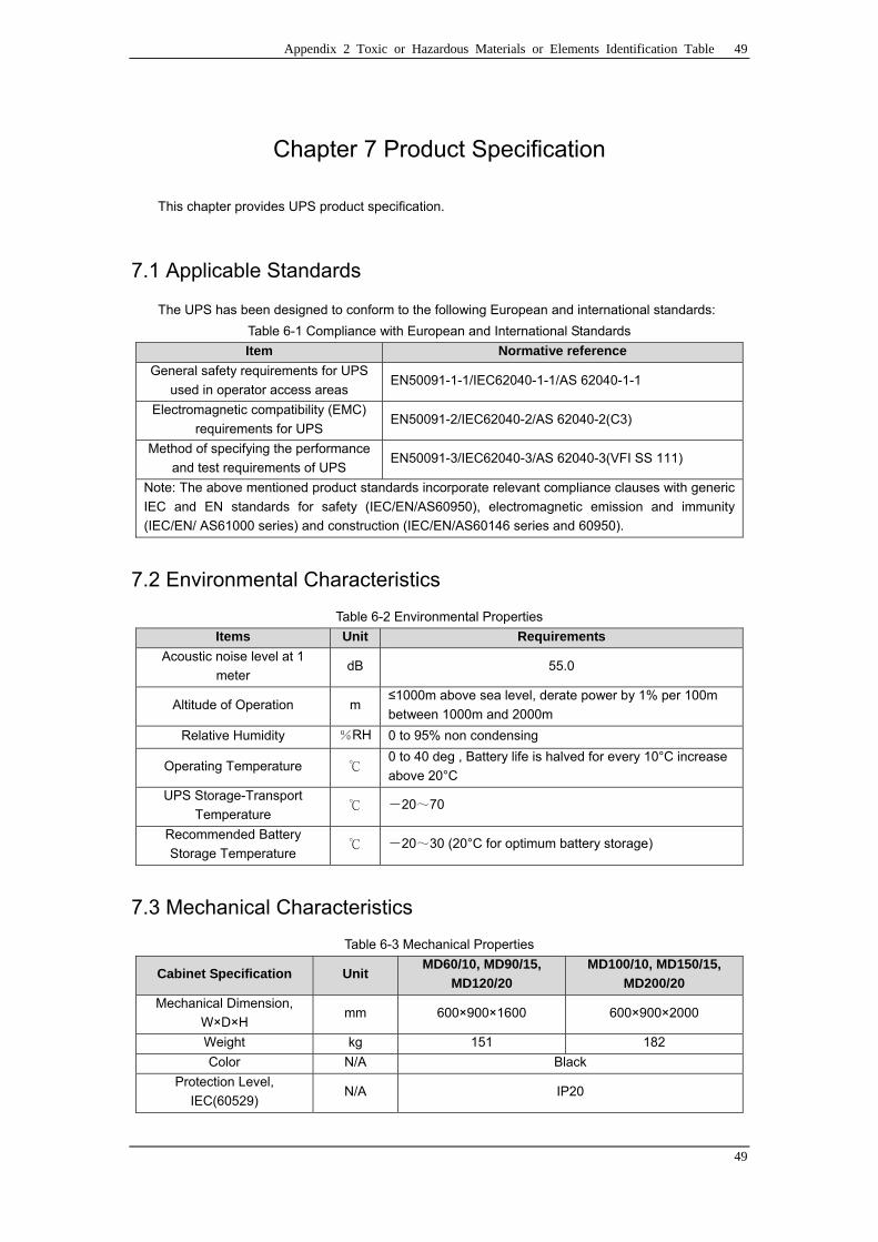
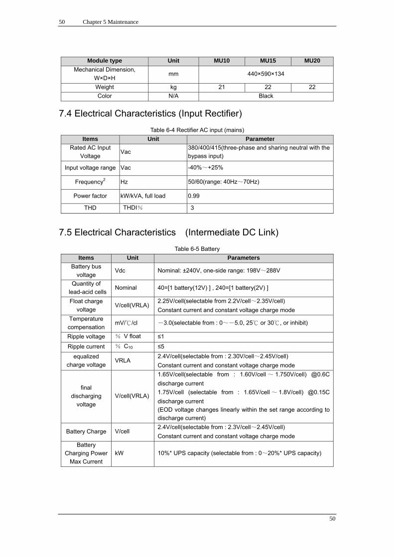
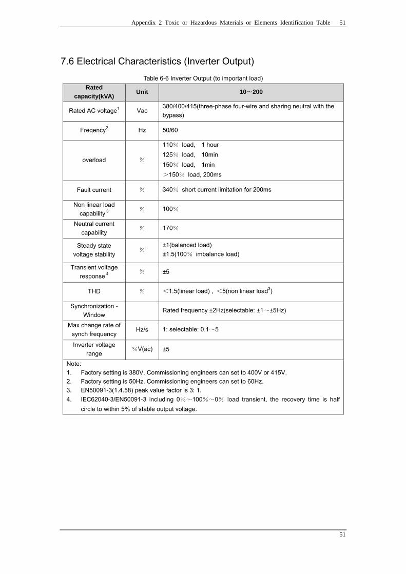
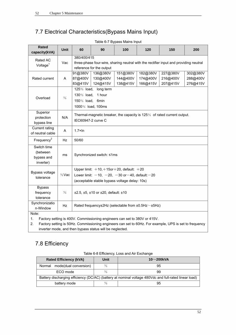
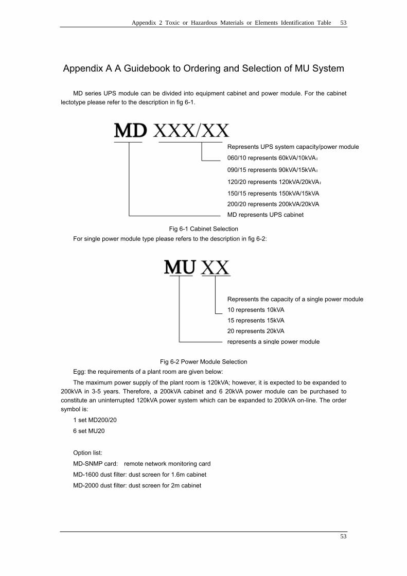