Embed Size (px)
Citation preview

PASSION FOR POWER.
ENYSTAR
Modular VTPN Distribution Board System up to 250 A
according to IEC 61439-3
for commercial and industrial buildings
Download at www.hensel.in
+assembled in
INDIAdesigned in
GERMANY
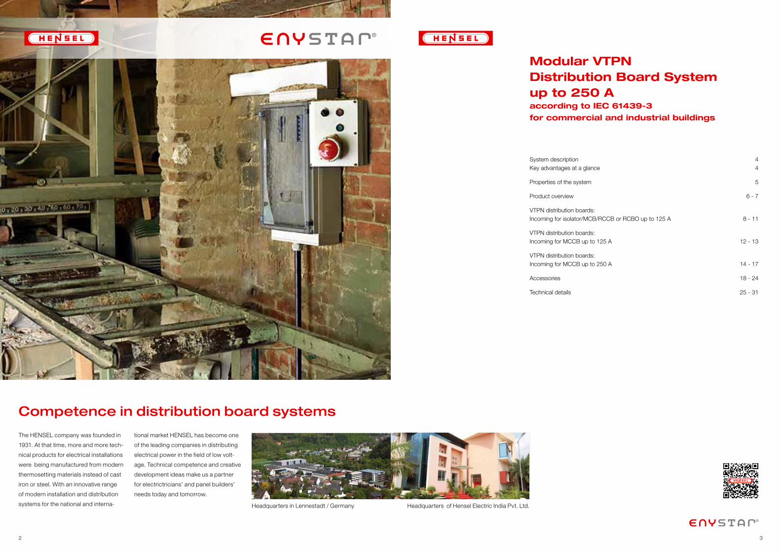
Competence in distribution board systems
The HENSEL company was founded in
1931. At that time, more and more tech-
nical products for electrical installations
were being manufactured from modern
thermosetting materials instead of cast
iron or steel. With an innovative range
of modern installation and distribution
systems for the national and interna-
tional market HENSEL has become one
of the leading companies in distributing
electrical power in the field of low volt-
age. Technical competence and creative
development ideas make us a partner
for electrictricians’ and panel builders’
needs today and tomorrow.
Headquarters of Hensel Electric India Pvt. Ltd. Headquarters in Lennestadt / Germany
Modular VTPN Distribution Board Systemup to 250 Aaccording to IEC 61439-3
for commercial and industrial buildings
System description 4 Key advantages at a glance 4
Properties of the system 5
Product overview 6 - 7
VTPN distribution boards: Incoming for isolator/MCB/RCCB or RCBO up to 125 A 8 - 11
VTPN distribution boards: Incoming for MCCB up to 125 A 12 - 13
VTPN distribution boards: Incoming for MCCB up to 250 A 14 - 17
Accessories 18 - 24
Technical details 25 - 31
32
wiSilicone- and halogene-free
VTPN Distribution Board System up to 250 A
54
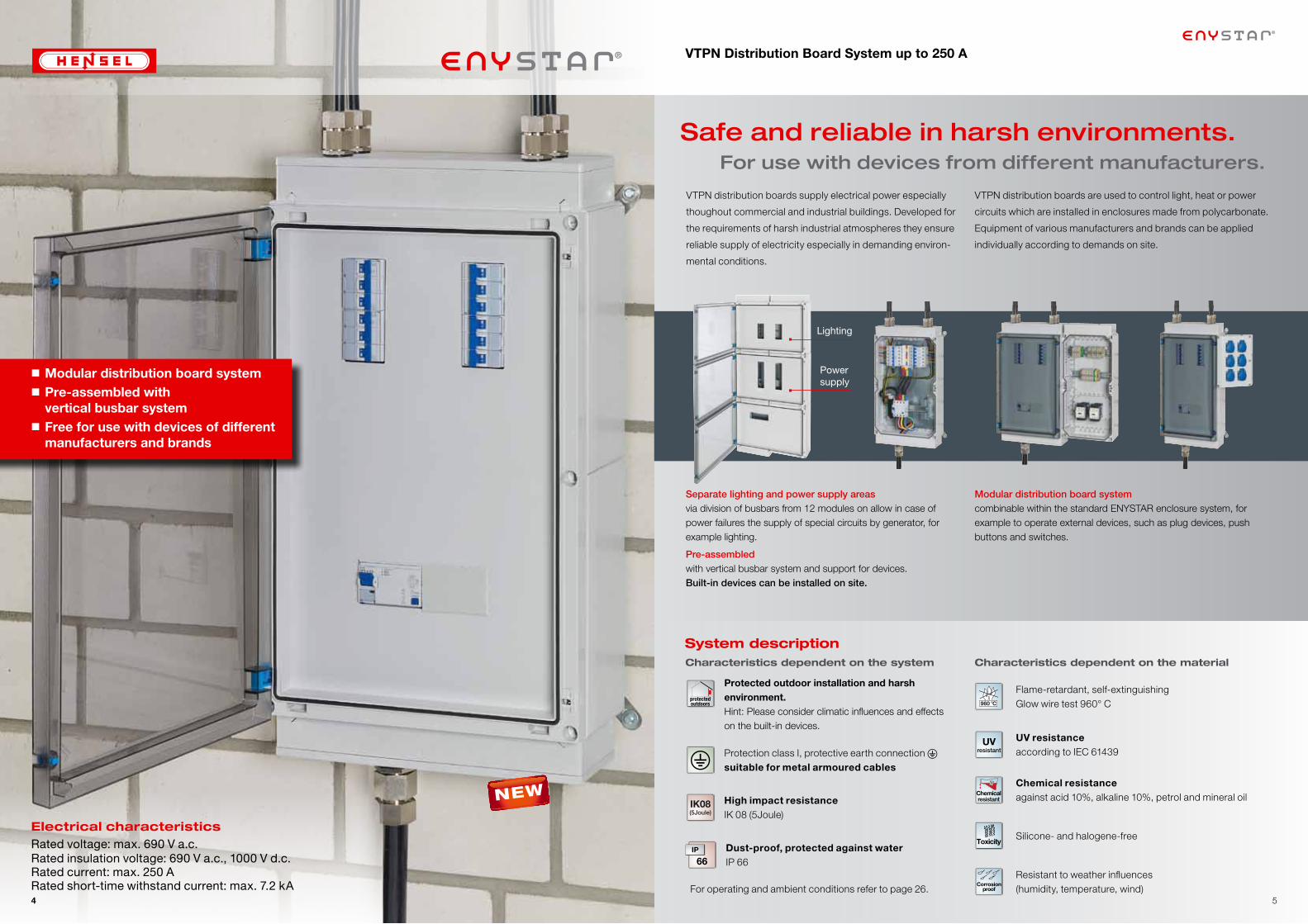
Electrical characteristicsRated voltage: max. 690 V a.c.Rated insulation voltage: 690 V a.c., 1000 V d.c.Rated current: max. 250 ARated short-time withstand current: max. 7.2 kA
NEW
Safe and reliable in harsh environments. For use with devices from different manufacturers.
System descriptionCharacteristics dependent on the system
Dust-proof, protected against waterIP 66
High impact resistanceIK 08 (5Joule)
IK08(5Joule)
Protected outdoor installation and harsh environment. Hint: Please consider climatic influences and effects on the built-in devices.
protectedoutdoors
Protection class I, protective earth connection suitable for metal armoured cables �
Separate lighting and power supply areasvia division of busbars from 12 modules on allow in case of power failures the supply of special circuits by generator, for example lighting.
Pre-assembled with vertical busbar system and support for devices. Built-in devices can be installed on site.
Lighting
Power supply
Characteristics dependent on the material
Flame-retardant, self-extinguishing Glow wire test 960° C
Resistant to weather influences (humidity, temperature, wind)
Corrosionproof
Silicone- and halogene-freeToxicity
UV resistance according to IEC 61439
UVresistant
Chemical resistance against acid 10%, alkaline 10%, petrol and mineral oilChemical
resistant
Modular distribution board systemcombinable within the standard ENYSTAR enclosure system, for example to operate external devices, such as plug devices, push buttons and switches.
VTPN distribution boards are used to control light, heat or power
circuits which are installed in enclosures made from polycarbonate.
Equipment of various manufacturers and brands can be applied
individually according to demands on site.
VTPN distribution boards supply electrical power especially
thoughout commercial and industrial buildings. Developed for
the requirements of harsh industrial atmospheres they ensure
reliable supply of electricity especially in demanding environ-
mental conditions.
For operating and ambient conditions refer to page 26.
Modular distribution board system Pre-assembled with
vertical busbar system Free for use with devices of different
manufacturers and brands
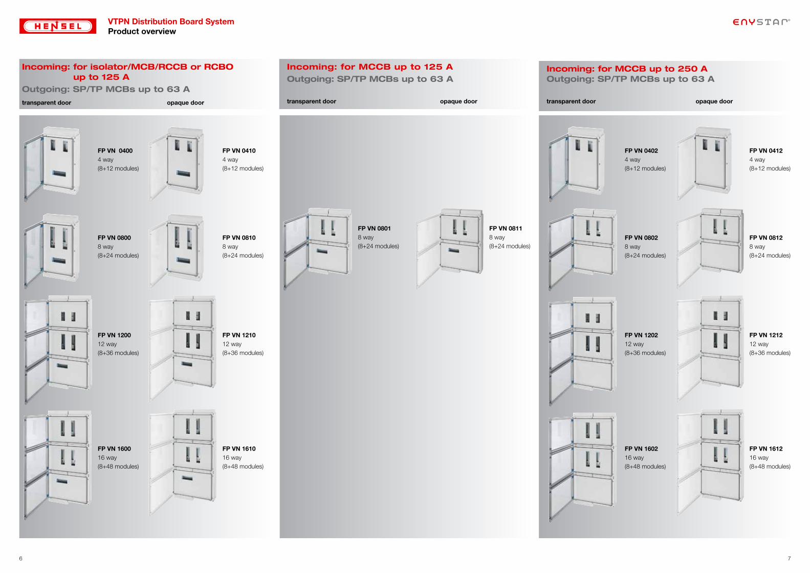
VTPN Distribution Board System Product overview
Incoming: for isolator/MCB/RCCB or RCBO up to 125 A
Outgoing: SP/TP MCBs up to 63 A
transparent door opaque door
Incoming: for MCCB up to 125 AOutgoing: SP/TP MCBs up to 63 A
transparent door opaque door
Incoming: for MCCB up to 250 A Outgoing: SP/TP MCBs up to 63 A
transparent door opaque door
76
FP VN 04004 way (8+12 modules)
FP VN 120012 way (8+36 modules)
FP VN 08008 way (8+24 modules)
FP VN 160016 way (8+48 modules)
FP VN 04104 way (8+12 modules)
FP VN 121012 way (8+36 modules)
FP VN 08108 way (8+24 modules)
FP VN 161016 way (8+48 modules)
FP VN 08018 way (8+24 modules)
FP VN 08118 way (8+24 modules)
FP VN 04024 way (8+12 modules)
FP VN 160216 way (8+48 modules)
FP VN 08028 way (8+24 modules)
FP VN 120212 way (8+36 modules)
FP VN 04124 way (8+12 modules)
FP VN 161216 way (8+48 modules)
FP VN 08128 way (8+24 modules)
FP VN 121212 way (8+36 modules)
8 9
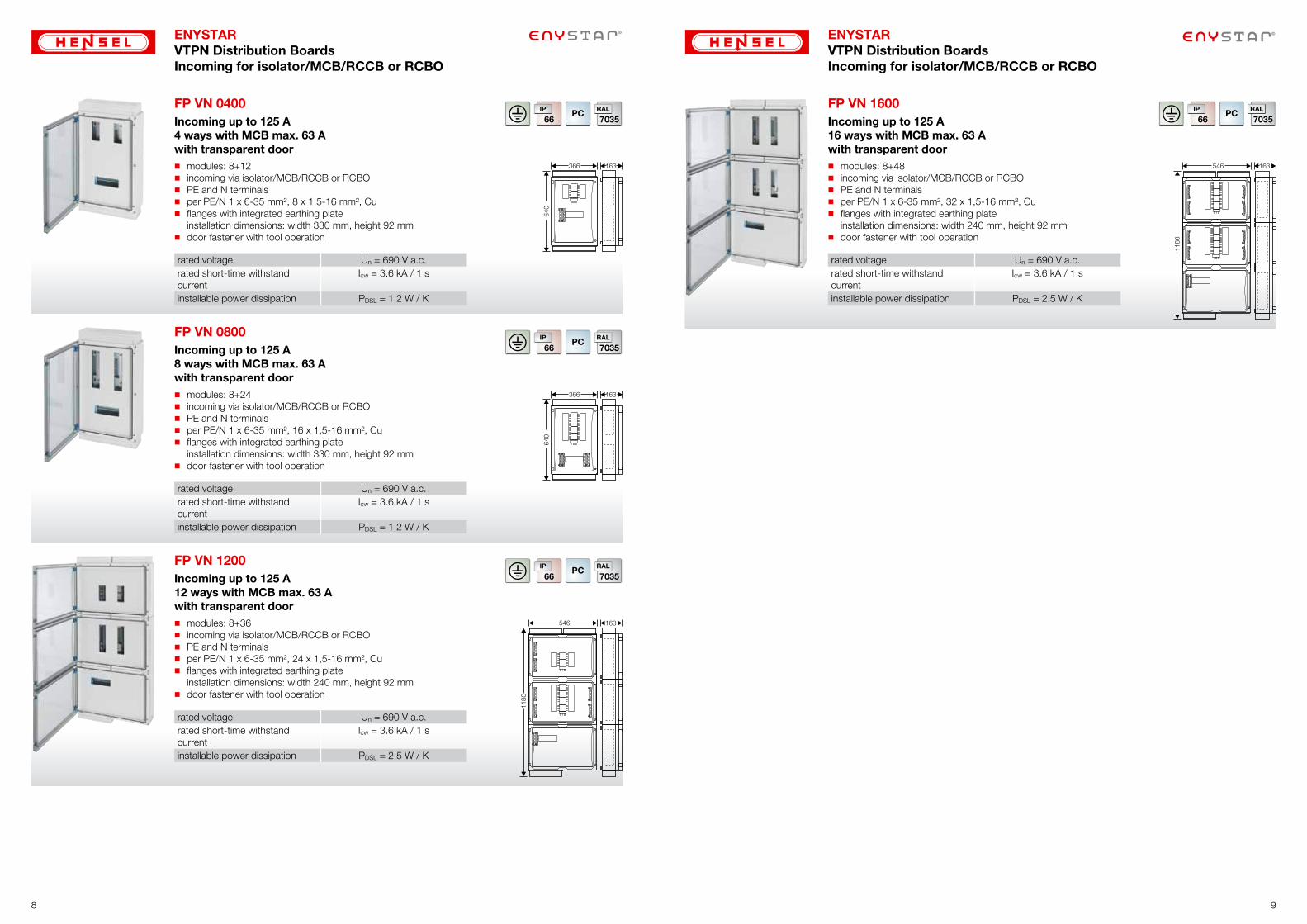
ENYSTARVTPN Distribution BoardsIncoming for isolator/MCB/RCCB or RCBO
ENYSTARVTPN Distribution BoardsIncoming for isolator/MCB/RCCB or RCBO
FP VN 0400 � Incoming up to 125 A
4 ways with MCB max. 63 Awith transparent door� modules: 8+12� incoming via isolator/MCB/RCCB or RCBO� PE and N terminals� per PE/N 1 x 6-35 mm², 8 x 1,5-16 mm², Cu� flanges with integrated earthing plate
installation dimensions: width 330 mm, height 92 mm� door fastener with tool operation
rated voltage Un = 690 V a.c.rated short-time withstand current
Icw = 3.6 kA / 1 s
installable power dissipation PDSL = 1.2 W / K
163
640
366
FP VN 0800 � Incoming up to 125 A
8 ways with MCB max. 63 Awith transparent door� modules: 8+24� incoming via isolator/MCB/RCCB or RCBO� PE and N terminals� per PE/N 1 x 6-35 mm², 16 x 1,5-16 mm², Cu� flanges with integrated earthing plate
installation dimensions: width 330 mm, height 92 mm� door fastener with tool operation
rated voltage Un = 690 V a.c.rated short-time withstand current
Icw = 3.6 kA / 1 s
installable power dissipation PDSL = 1.2 W / K
163
640
366
FP VN 1200 � Incoming up to 125 A
12 ways with MCB max. 63 Awith transparent door� modules: 8+36� incoming via isolator/MCB/RCCB or RCBO� PE and N terminals� per PE/N 1 x 6-35 mm², 24 x 1,5-16 mm², Cu� flanges with integrated earthing plate
installation dimensions: width 240 mm, height 92 mm� door fastener with tool operation
rated voltage Un = 690 V a.c.rated short-time withstand current
Icw = 3.6 kA / 1 s
installable power dissipation PDSL = 2.5 W / K
163546
1180
FP VN 1600 � Incoming up to 125 A
16 ways with MCB max. 63 Awith transparent door� modules: 8+48� incoming via isolator/MCB/RCCB or RCBO� PE and N terminals� per PE/N 1 x 6-35 mm², 32 x 1,5-16 mm², Cu� flanges with integrated earthing plate
installation dimensions: width 240 mm, height 92 mm� door fastener with tool operation
rated voltage Un = 690 V a.c.rated short-time withstand current
Icw = 3.6 kA / 1 s
installable power dissipation PDSL = 2.5 W / K
163546
1180
10 11
ENYSTARVTPN Distribution BoardsIncoming for isolator/MCB/RCCB or RCBO
ENYSTARVTPN Distribution BoardsIncoming for isolator/MCB/RCCB or RCBO
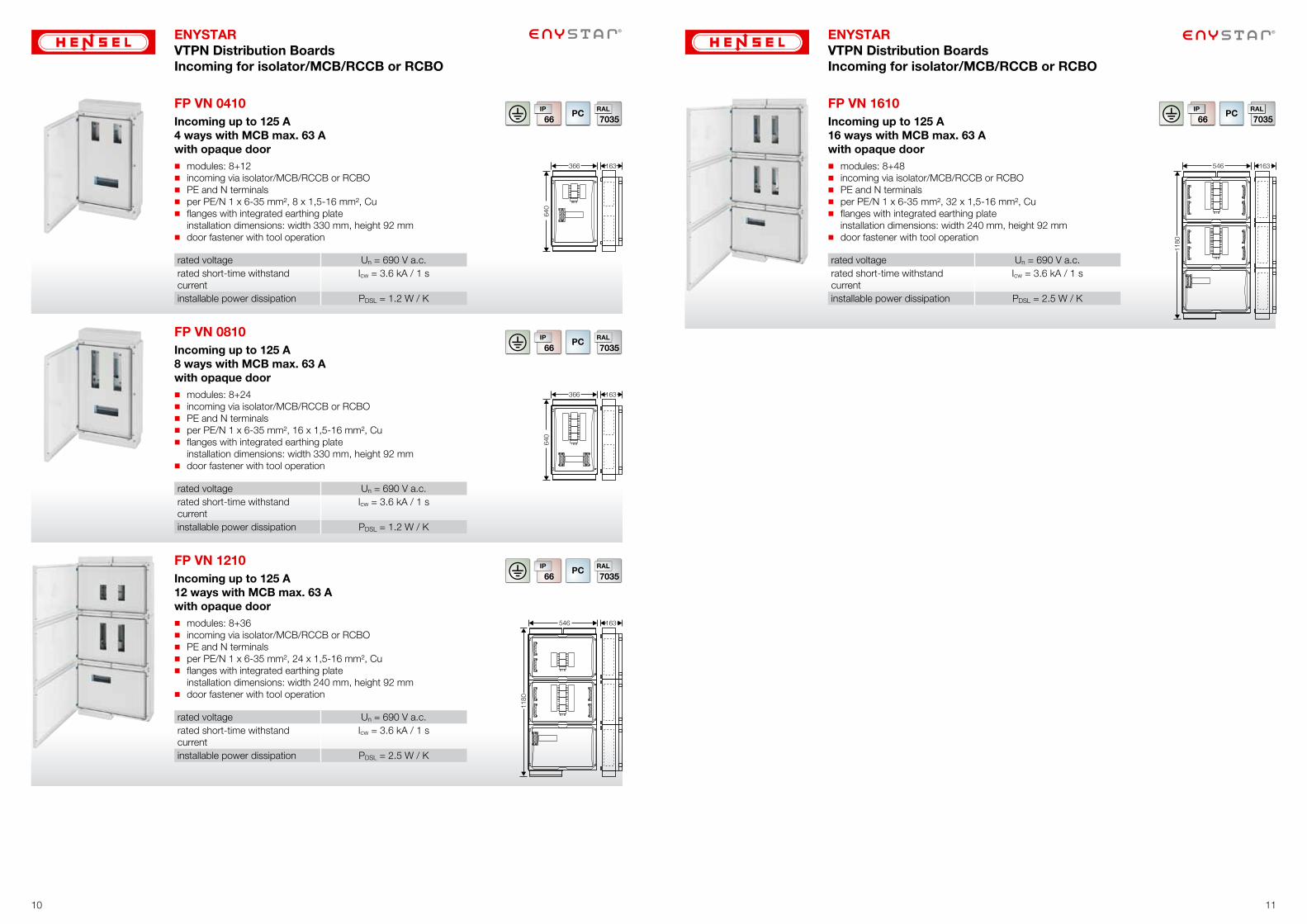
FP VN 0410 � Incoming up to 125 A
4 ways with MCB max. 63 Awith opaque door� modules: 8+12� incoming via isolator/MCB/RCCB or RCBO� PE and N terminals� per PE/N 1 x 6-35 mm², 8 x 1,5-16 mm², Cu� flanges with integrated earthing plate
installation dimensions: width 330 mm, height 92 mm� door fastener with tool operation
rated voltage Un = 690 V a.c.rated short-time withstand current
Icw = 3.6 kA / 1 s
installable power dissipation PDSL = 1.2 W / K
163
640
366
FP VN 0810 � Incoming up to 125 A
8 ways with MCB max. 63 Awith opaque door� modules: 8+24� incoming via isolator/MCB/RCCB or RCBO� PE and N terminals� per PE/N 1 x 6-35 mm², 16 x 1,5-16 mm², Cu� flanges with integrated earthing plate
installation dimensions: width 330 mm, height 92 mm� door fastener with tool operation
rated voltage Un = 690 V a.c.rated short-time withstand current
Icw = 3.6 kA / 1 s
installable power dissipation PDSL = 1.2 W / K
163
640
366
FP VN 1210 � Incoming up to 125 A
12 ways with MCB max. 63 Awith opaque door� modules: 8+36� incoming via isolator/MCB/RCCB or RCBO� PE and N terminals� per PE/N 1 x 6-35 mm², 24 x 1,5-16 mm², Cu� flanges with integrated earthing plate
installation dimensions: width 240 mm, height 92 mm� door fastener with tool operation
rated voltage Un = 690 V a.c.rated short-time withstand current
Icw = 3.6 kA / 1 s
installable power dissipation PDSL = 2.5 W / K
163546
1180
FP VN 1610 � Incoming up to 125 A
16 ways with MCB max. 63 Awith opaque door� modules: 8+48� incoming via isolator/MCB/RCCB or RCBO� PE and N terminals� per PE/N 1 x 6-35 mm², 32 x 1,5-16 mm², Cu� flanges with integrated earthing plate
installation dimensions: width 240 mm, height 92 mm� door fastener with tool operation
rated voltage Un = 690 V a.c.rated short-time withstand current
Icw = 3.6 kA / 1 s
installable power dissipation PDSL = 2.5 W / K
163546
1180
12 13
ENYSTARVTPN Distribution BoardsIncoming for MCCB
ENYSTARVTPN Distribution BoardsIncoming for MCCB
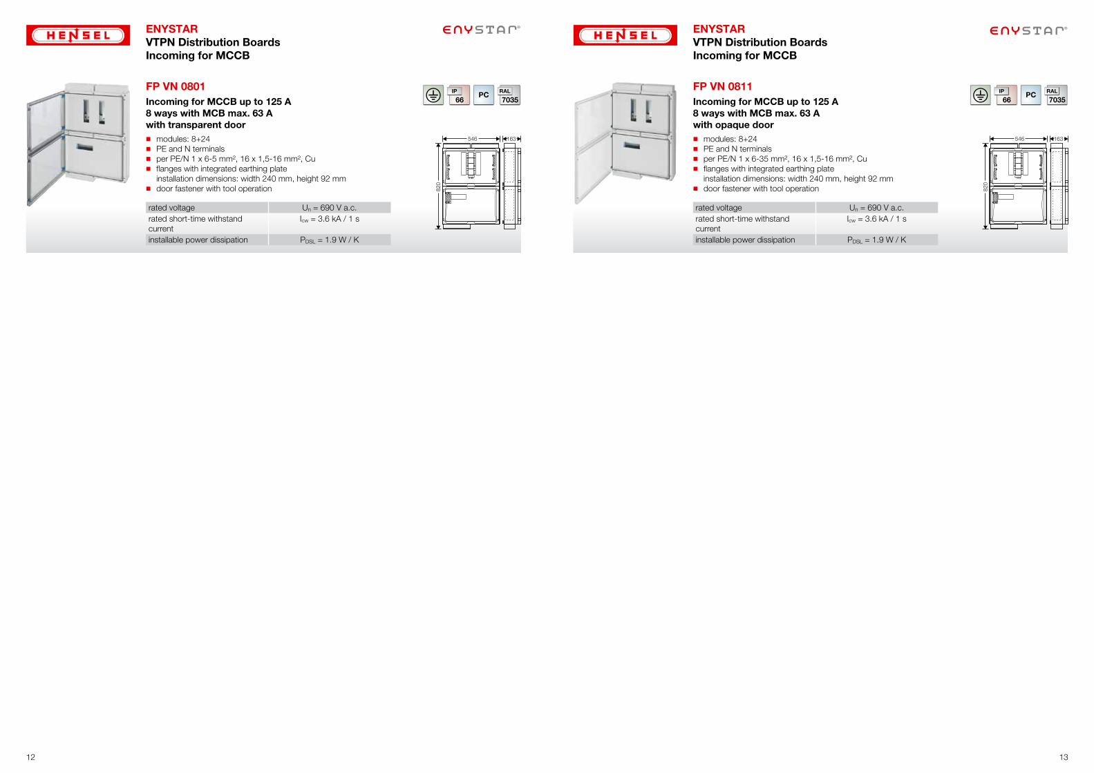
FP VN 0801 � Incoming for MCCB up to 125 A
8 ways with MCB max. 63 Awith transparent door� modules: 8+24� PE and N terminals� per PE/N 1 x 6-5 mm², 16 x 1,5-16 mm², Cu� flanges with integrated earthing plate
installation dimensions: width 240 mm, height 92 mm� door fastener with tool operation
rated voltage Un = 690 V a.c.rated short-time withstand current
Icw = 3.6 kA / 1 s
installable power dissipation PDSL = 1.9 W / K
163546
820
FP VN 0811 � Incoming for MCCB up to 125 A
8 ways with MCB max. 63 Awith opaque door� modules: 8+24� PE and N terminals� per PE/N 1 x 6-35 mm², 16 x 1,5-16 mm², Cu� flanges with integrated earthing plate
installation dimensions: width 240 mm, height 92 mm� door fastener with tool operation
rated voltage Un = 690 V a.c.rated short-time withstand current
Icw = 3.6 kA / 1 s
installable power dissipation PDSL = 1.9 W / K
163546
820
14 15
ENYSTARVTPN Distribution BoardsIncoming for MCCB
ENYSTARVTPN Distribution BoardsIncoming for MCCB
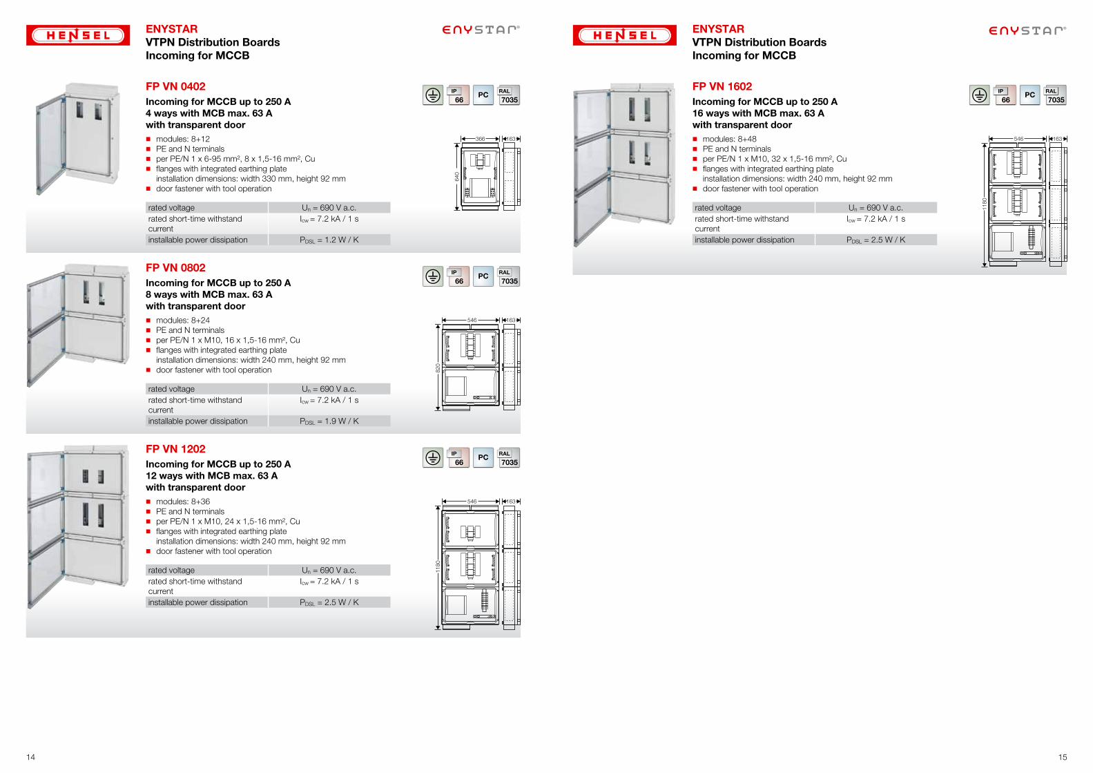
FP VN 0402 � Incoming for MCCB up to 250 A
4 ways with MCB max. 63 Awith transparent door� modules: 8+12� PE and N terminals� per PE/N 1 x 6-95 mm², 8 x 1,5-16 mm², Cu� flanges with integrated earthing plate
installation dimensions: width 330 mm, height 92 mm� door fastener with tool operation
rated voltage Un = 690 V a.c.rated short-time withstand current
Icw = 7.2 kA / 1 s
installable power dissipation PDSL = 1.2 W / K
163
640
366
FP VN 0802 � Incoming for MCCB up to 250 A
8 ways with MCB max. 63 Awith transparent door� modules: 8+24� PE and N terminals� per PE/N 1 x M10, 16 x 1,5-16 mm², Cu� flanges with integrated earthing plate
installation dimensions: width 240 mm, height 92 mm� door fastener with tool operation
rated voltage Un = 690 V a.c.rated short-time withstand current
Icw = 7.2 kA / 1 s
installable power dissipation PDSL = 1.9 W / K
163546
820
FP VN 1202
�
Incoming for MCCB up to 250 A12 ways with MCB max. 63 Awith transparent door� modules: 8+36� PE and N terminals� per PE/N 1 x M10, 24 x 1,5-16 mm², Cu� flanges with integrated earthing plate
installation dimensions: width 240 mm, height 92 mm� door fastener with tool operation
rated voltage Un = 690 V a.c.rated short-time withstand current
Icw = 7.2 kA / 1 s
installable power dissipation PDSL = 2.5 W / K
163546
1180
FP VN 1602 � Incoming for MCCB up to 250 A
16 ways with MCB max. 63 Awith transparent door� modules: 8+48� PE and N terminals� per PE/N 1 x M10, 32 x 1,5-16 mm², Cu� flanges with integrated earthing plate
installation dimensions: width 240 mm, height 92 mm� door fastener with tool operation
rated voltage Un = 690 V a.c.rated short-time withstand current
Icw = 7.2 kA / 1 s
installable power dissipation PDSL = 2.5 W / K
163546
1180
16 17
ENYSTARVTPN Distribution BoardsIncoming for MCCB
ENYSTARVTPN Distribution BoardsIncoming for MCCB
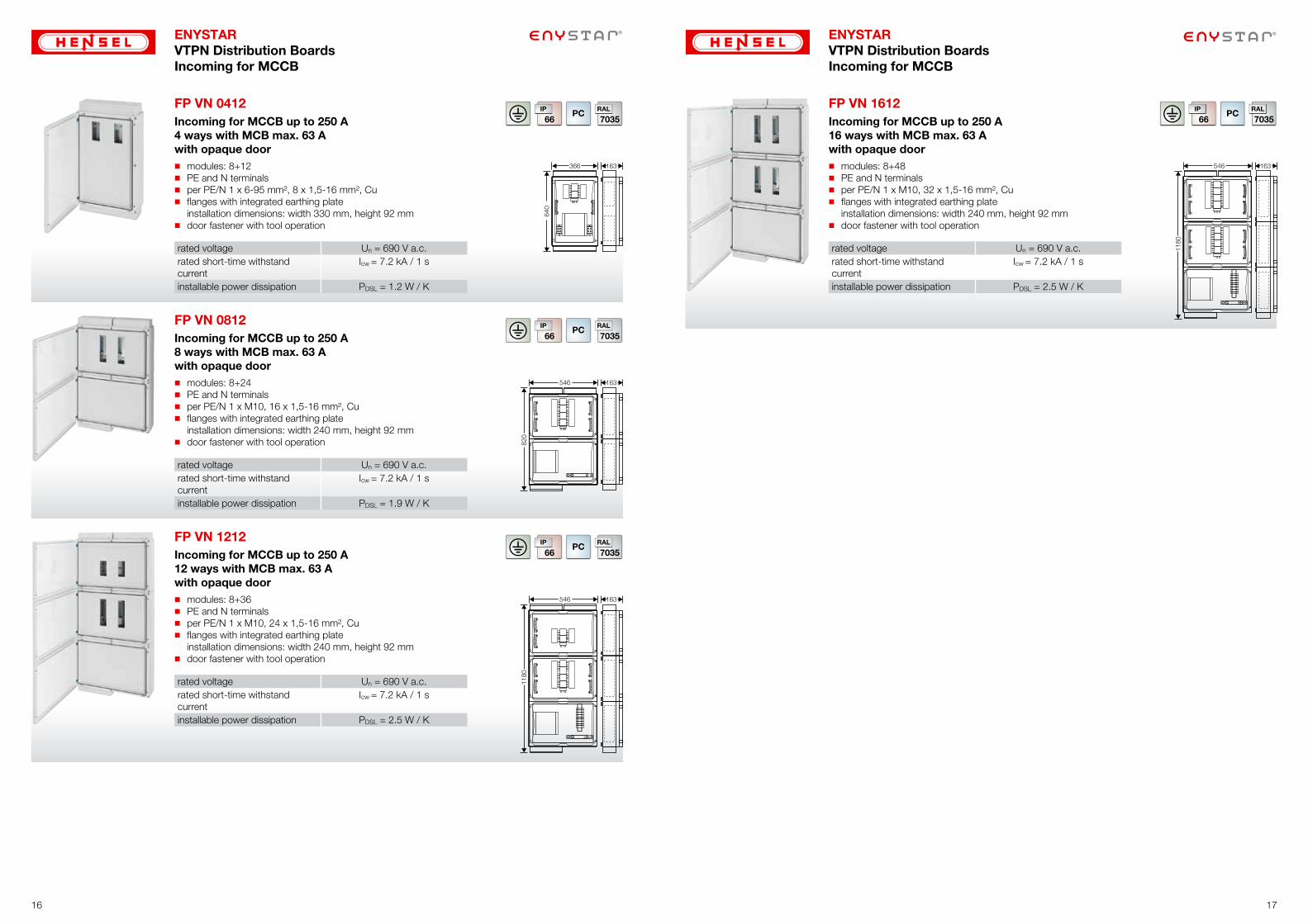
FP VN 0412 � Incoming for MCCB up to 250 A
4 ways with MCB max. 63 Awith opaque door� modules: 8+12� PE and N terminals� per PE/N 1 x 6-95 mm², 8 x 1,5-16 mm², Cu� flanges with integrated earthing plate
installation dimensions: width 330 mm, height 92 mm� door fastener with tool operation
rated voltage Un = 690 V a.c.rated short-time withstand current
Icw = 7.2 kA / 1 s
installable power dissipation PDSL = 1.2 W / K
163
640
366
FP VN 0812 � Incoming for MCCB up to 250 A
8 ways with MCB max. 63 Awith opaque door� modules: 8+24� PE and N terminals� per PE/N 1 x M10, 16 x 1,5-16 mm², Cu� flanges with integrated earthing plate
installation dimensions: width 240 mm, height 92 mm� door fastener with tool operation
rated voltage Un = 690 V a.c.rated short-time withstand current
Icw = 7.2 kA / 1 s
installable power dissipation PDSL = 1.9 W / K
163546
820
FP VN 1212 � Incoming for MCCB up to 250 A
12 ways with MCB max. 63 Awith opaque door� modules: 8+36� PE and N terminals� per PE/N 1 x M10, 24 x 1,5-16 mm², Cu� flanges with integrated earthing plate
installation dimensions: width 240 mm, height 92 mm� door fastener with tool operation
rated voltage Un = 690 V a.c.rated short-time withstand current
Icw = 7.2 kA / 1 s
installable power dissipation PDSL = 2.5 W / K
163546
1180
FP VN 1612 � Incoming for MCCB up to 250 A
16 ways with MCB max. 63 Awith opaque door� modules: 8+48� PE and N terminals� per PE/N 1 x M10, 32 x 1,5-16 mm², Cu� flanges with integrated earthing plate
installation dimensions: width 240 mm, height 92 mm� door fastener with tool operation
rated voltage Un = 690 V a.c.rated short-time withstand current
Icw = 7.2 kA / 1 s
installable power dissipation PDSL = 2.5 W / K
163546
1180
ENYSTARAccessories
Connection Box 19
Sealing device for covers, blanking strips 20
Closing plates, metal insert for closing plates 21
Flanges for cable entry 22
Ventilation flanges 23
Fixing devices 24
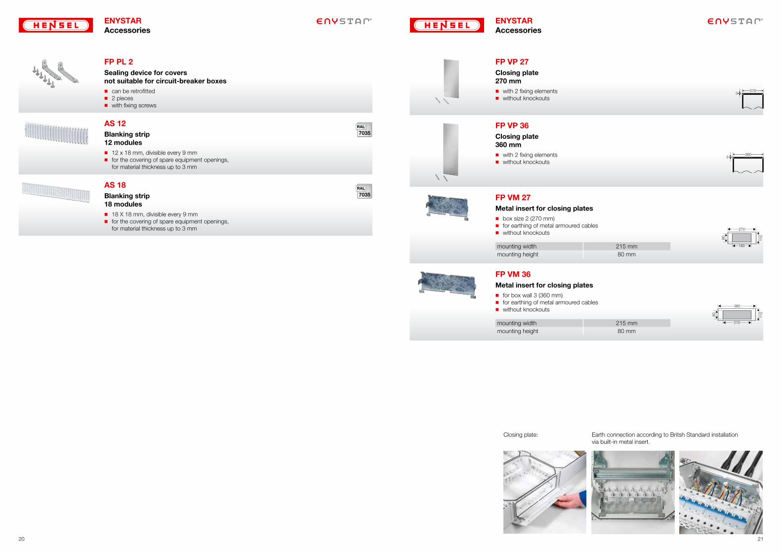
Example:The Connection Box allows a simple and fast instal-lation of devices that must be operated externally, such as plug devices, push buttons and switches.
1918
ENYSTARAccessories
FP CB 210
Connection Box
� for mounting on box walls (270 mm)� hinged mounting area� for the installation of devices that must be operated externally,
such as plug devices, push buttons and switches
270215
158
180
45
125
FP PL 2Sealing device for coversnot suitable for circuit-breaker boxes� can be retrofitted� 2 pieces� with fixing screws
AS 12
Blanking strip12 modules� 12 x 18 mm, divisible every 9 mm� for the covering of spare equipment openings,
for material thickness up to 3 mm
AS 18
Blanking strip18 modules� 18 X 18 mm, divisible every 9 mm� for the covering of spare equipment openings,
for material thickness up to 3 mm
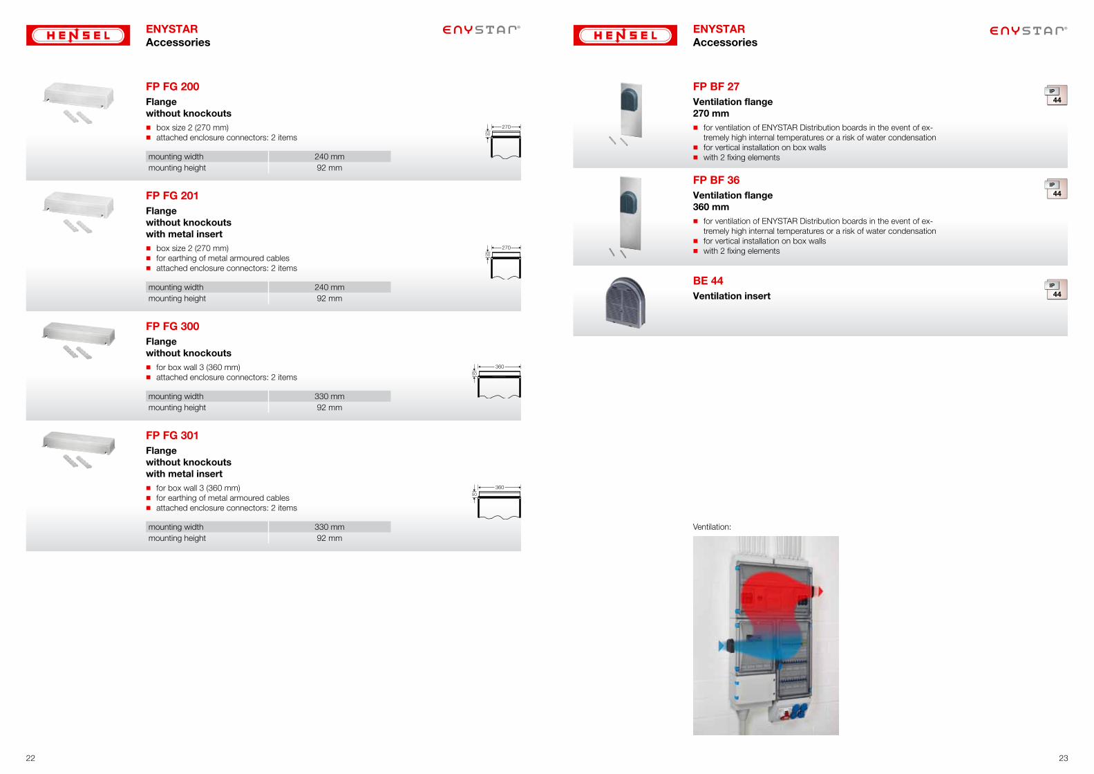
FP VP 27Closing plate270 mm� with 2 fixing elements� without knockouts
FP VP 36Closing plate360 mm� with 2 fixing elements� without knockouts
FP VM 27Metal insert for closing plates� box size 2 (270 mm)� for earthing of metal armoured cables� without knockouts
mounting width 215 mmmounting height 80 mm
���
���
���
��
FP VM 36Metal insert for closing plates� for box wall 3 (360 mm)� for earthing of metal armoured cables� without knockouts
mounting width 215 mmmounting height 80 mm
���
���
���
��
Closing plate: Earth connection according to Britsh Standard installation via built-in metal insert.
2120
ENYSTARAccessories
ENYSTARAccessories
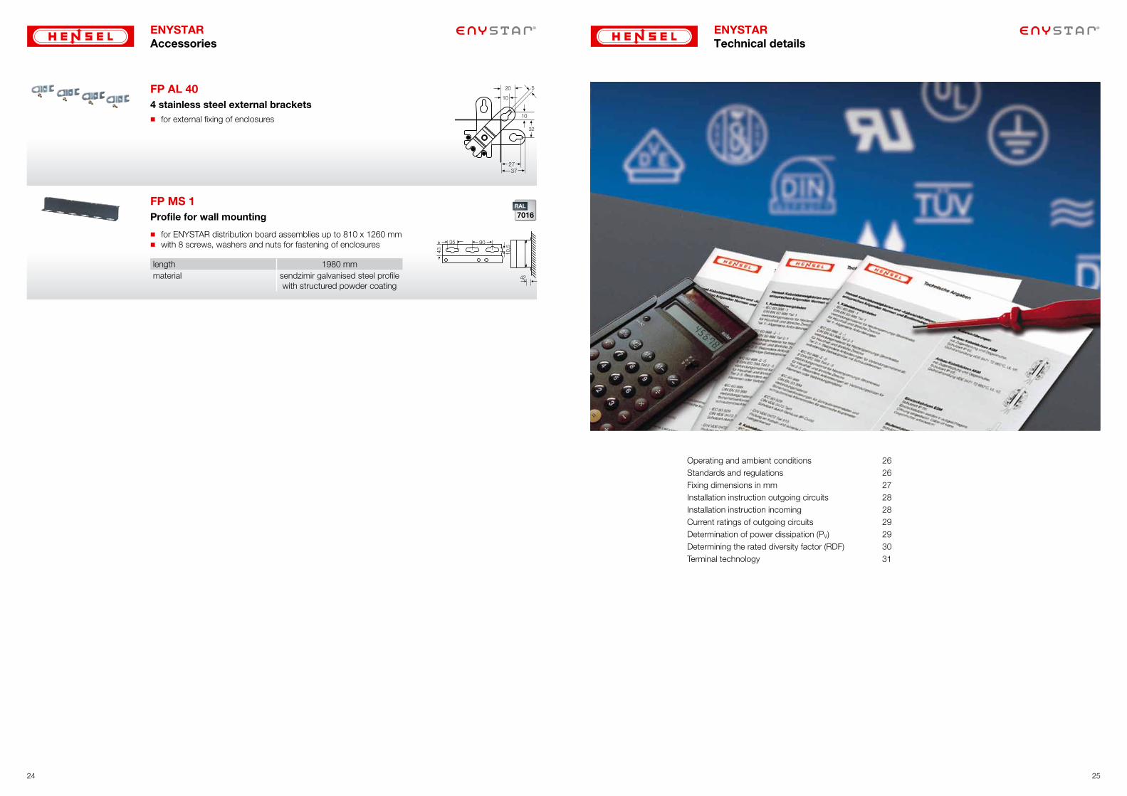
Ventilation:
22 23
ENYSTARAccessories
FP FG 200Flangewithout knockouts� box size 2 (270 mm)� attached enclosure connectors: 2 items
mounting width 240 mmmounting height 92 mm
FP FG 201Flangewithout knockoutswith metal insert� box size 2 (270 mm)� for earthing of metal armoured cables� attached enclosure connectors: 2 items
mounting width 240 mmmounting height 92 mm
FP FG 300Flangewithout knockouts� for box wall 3 (360 mm)� attached enclosure connectors: 2 items
mounting width 330 mmmounting height 92 mm
FP FG 301Flangewithout knockoutswith metal insert� for box wall 3 (360 mm)� for earthing of metal armoured cables� attached enclosure connectors: 2 items
mounting width 330 mmmounting height 92 mm
ENYSTARAccessories
FP BF 36
Ventilation flange360 mm� for ventilation of ENYSTAR Distribution boards in the event of ex-
tremely high internal temperatures or a risk of water condensation� for vertical installation on box walls� with 2 fixing elements
FP BF 27
Ventilation flange270 mm� for ventilation of ENYSTAR Distribution boards in the event of ex-
tremely high internal temperatures or a risk of water condensation� for vertical installation on box walls� with 2 fixing elements
BE 44
Ventilation insert
ENYSTARTechnical details
Operating and ambient conditions 26Standards and regulations 26Fixing dimensions in mm 27Installation instruction outgoing circuits 28 Installation instruction incoming 28Current ratings of outgoing circuits 29Determination of power dissipation (PV) 29Determining the rated diversity factor (RDF) 30Terminal technology 31
2524
FP AL 40
2737
4 stainless steel external brackets� for external fixing of enclosures
FP MS 1
Profile for wall mounting
� for ENYSTAR distribution board assemblies up to 810 x 1260 mm� with 8 screws, washers and nuts for fastening of enclosures
length 1980 mmmaterial sendzimir galvanised steel profile
with structured powder coating
ENYSTARAccessories
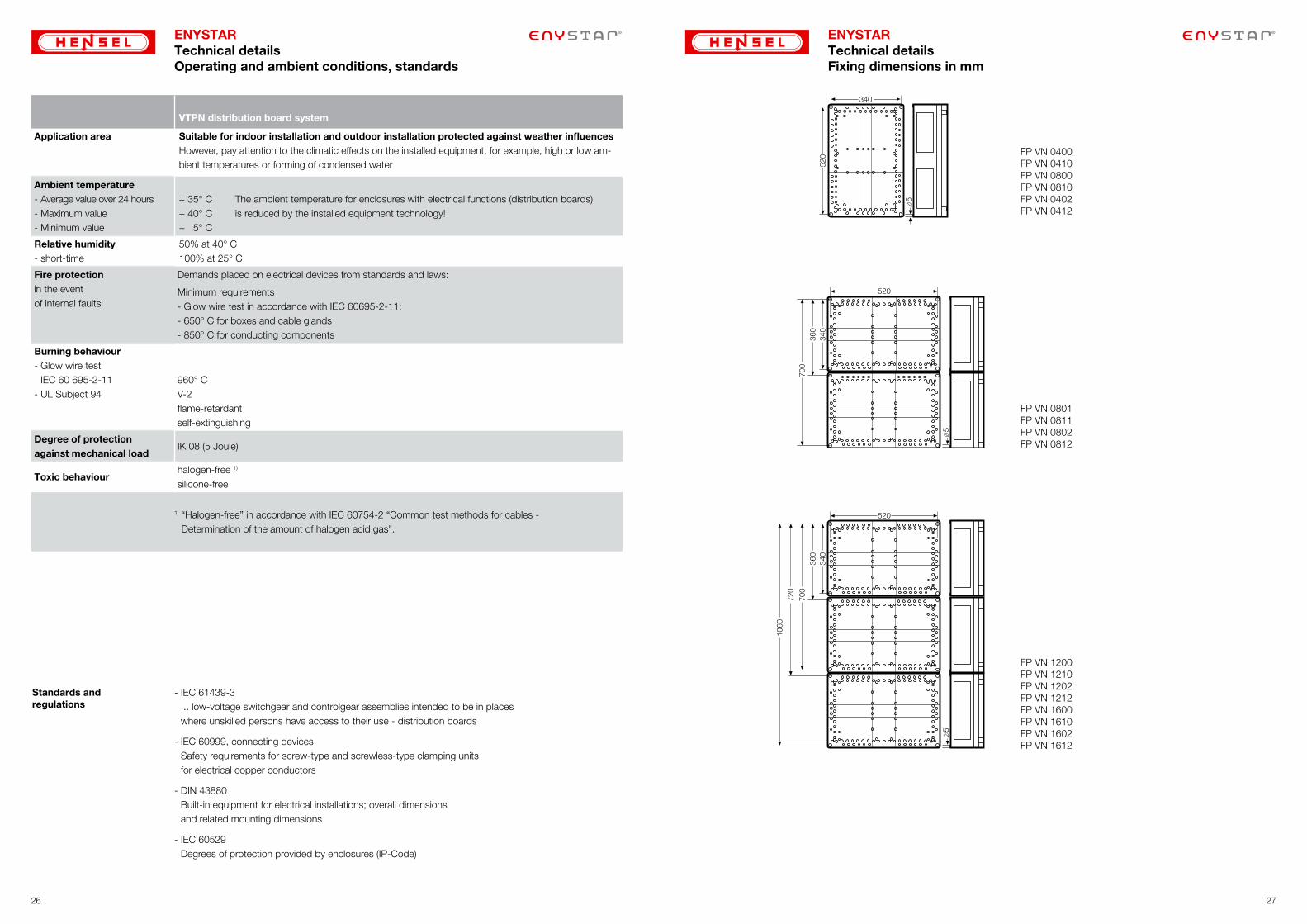
ENYSTARTechnical detailsOperating and ambient conditions, standards
VTPN distribution board system
Application area Suitable for indoor installation and outdoor installation protected against weather influencesHowever, pay attention to the climatic effects on the installed equipment, for example, high or low am-bient temperatures or forming of condensed water
Ambient temperature- Average value over 24 hours- Maximum value- Minimum value
+ 35° C+ 40° C− 5° C
The ambient temperature for enclosures with electrical functions (distribution boards) is reduced by the installed equipment technology!
Relative humidity- short-time
50% at 40° C100% at 25° C
Fire protectionin the event of internal faults
Demands placed on electrical devices from standards and laws:
Minimum requirements- Glow wire test in accordance with IEC 60695-2-11:- 650° C for boxes and cable glands - 850° C for conducting components
Burning behaviour- Glow wire test
IEC 60 695-2-11- UL Subject 94
960° CV-2flame-retardantself-extinguishing
Degree of protection against mechanical load
IK 08 (5 Joule)
Toxic behaviourhalogen-free 1)
silicone-free
1) “Halogen-free” in accordance with IEC 60754-2 “Common test methods for cables - Determination of the amount of halogen acid gas”.
- IEC 61439-3 ... low-voltage switchgear and controlgear assemblies intended to be in places where unskilled persons have access to their use - distribution boards
- IEC 60999, connecting devices Safety requirements for screw-type and screwless-type clamping units for electrical copper conductors
- DIN 43880 Built-in equipment for electrical installations; overall dimensions and related mounting dimensions
- IEC 60529 Degrees of protection provided by enclosures (IP-Code)
Standards and regulations
ENYSTARTechnical detailsFixing dimensions in mm
FP VN 0400FP VN 0410FP VN 0800FP VN 0810FP VN 0402FP VN 0412
FP VN 0801FP VN 0811FP VN 0802FP VN 0812
700
700
720
1060
FP VN 1200FP VN 1210FP VN 1202FP VN 1212FP VN 1600FP VN 1610FP VN 1602FP VN 1612
2726
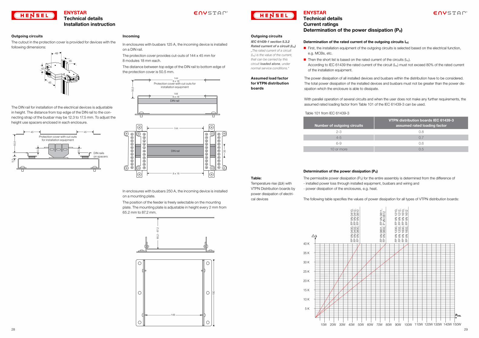
The cutout in the protection cover is provided for devices with the following dimensions:
The DIN rail for installation of the electrical devices is adjustable in height. The distance from top edge of the DIN rail to the con-necting strap of the busbar may be 12.3 to 17.5 mm. To adjust the height use spacers enclosed in each enclosure.
50,5
5,2
12,3
12,3
45 45
Protection cover with cut outs for installation equipment
DIN rails on spacers
ENYSTARTechnical detailsInstallation instruction
Outgoing circuits
In enclosures with busbars 250 A, the incoming device is installed on a mounting plate.
The position of the feeder is freely selectable on the mounting plate. The mounting plate is adjustable in height every 2 mm from 65.2 mm to 87.2 mm.
180
148
65,2
- 8
7,2
In enclosures with busbars 125 A, the incoming device is installed on a DIN rail.
The protection cover provides cut-outs of 144 x 45 mm for 8 modules 18 mm each.
The distance between top edge of the DIN rail to bottom edge of the protection cover is 50.5 mm.
144
8 x 18
35DIN rail
50,5
1448 x 18
1448 x 18
Protection cover with cut outs for installation equipment
DIN rail
Incoming
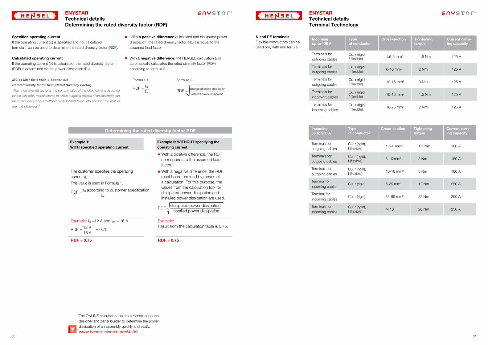
ENYSTARTechnical detailsCurrent ratingsDetermination of the power dissipation (PV)
First, the installation equipment of the outgoing circuits is selected based on the electrical function, e.g. MCBs, etc.
Then the short list is based on the rated current of the circuits (Inc). According to IEC 61439 the rated current of the circuit (Inc) must not exceed 80% of the rated current of the installation equipment.
Determination of the rated current of the outgoing circuits InC
Outgoing circuits
IEC 61439-1 section 5.3.2 Rated current of a circuit (Inc) „The rated current of a circuit (Inc) is the value of the current, that can be carried by this circuit loaded alone, under normal service conditions.“
Table 101 from IEC 61439-3
VTPN distribution boards IEC 61439-3Number of outgoing circuits assumed rated loading factor
2-3 0.8
4-5 0.7
6-9 0.6
10 or more 0.5
Assumed load factor for VTPN distribution boards
The power dissipation of all installed devices and busbars within the distribution have to be considered. The total power dissipation of the installed devices and busbars must not be greater than the power dis-sipation which the enclosure is able to dissipate.
With parallel operation of several circuits and when the user does not make any further requirements, the assumed rated loading factor from Table 101 of the IEC 61439-3 can be used.
DSL
FP V
N 1
200,
FP
VN
121
0,
FP V
N 1
202,
FP
VN
121
2,FP
VN
160
0, F
P V
N 1
610,
FP V
N 1
602,
FP
VN
161
2
FP V
N 0
801,
FP
VN
081
1,FP
VN
080
2, P
VN
081
2
FP V
N 0
400,
FP
VN
041
0,FP
VN
040
2, F
P V
N 0
412,
FP V
N 0
800,
FP
VN
081
0
110W 120W 130W 140W 150W
The permissible power dissipation (PV) for the entire assembly is determined from the difference of - installed power loss through installed equipment, busbars and wiring and- power dissipation of the enclosures, e.g. heat.
The following table specifies the values of power dissipation for all types of VTPN distribution boards:
Table:Temperature rise (∆J) with VTPN Distribution boards by power dissipation of electri-cal devices
Determination of the power dissipation (PV)
2928
ENYSTARTechnical detailsDetermining the rated diversity factor (RDF)
Determining the rated diversity factor RDF
Example 1:WITH specified operating current
Example 2: WITHOUT specifying the operating current
The customer specifies the operating current IB.
This value is used in Formula 1.
RDF = IB according to customer specification Inc
With a positive difference, the RDF corresponds to the assumed load factor.
With a negative difference, the RDF must be determined by means of a calculation. For this purpose, the values from the calculation tool for dissipated power dissipation and installed power dissipation are used.
RDF= dissipated power dissipation
installed power dissipation
Example: IB =12 A and Inc = 16 A
RDF = 12 A = 0.75 16 A
Example: Result from the calculation table is 0.75.
RDF = 0.75 RDF = 0.75
IEC 61439 / EN 61439 -1 Section 5.4
Rated diversity factor RDF (Rated Diversity Factor)
"The rated diversity factor is the per unit value of the rated current, assigned
by the assembly manufacturer, to which outgoing circuits of an assembly can
be continuously and simultaneaously loaded taken into account the mutual
thermal influences."
Specified operating current If the operating current (IB) is specified and not calculated, formula 1 can be used to determine the rated diversity factor (RDF).
Calculated operating current If the operating current (IB) is calculated, the rated diversity factor (RDF) is determined via the power dissipation (PV).
Formula 1:
RDF = IB Inc RDF =
dissipated power dissipation
installed power dissipation
Formula 2:
� With a positive difference of installed and dissipated power dissipation, the rated diversity factor (RDF) is equal to the assumed load factor.
� With a negative difference, the HENSEL calculation tool automatically calculates the rated diversity factor (RDF) according to formula 2.
The ONLINE calculation tool from Hensel supports designer and panel builder to determine the power dissipation of an assembly quickly and easily. www.hensel-electric.de/61439
ENYSTARTechnical detailsTerminal Technology
Incoming up to 125 A
Type of conductor
Cross-section Tightening torque
Current carry-ing capacity
Terminals for outgoing cables
Cu, r (rigid), f (flexible)
1,5-6 mm² 1,5 Nm 125 A
Terminals for outgoing cables
Cu, r (rigid), f (flexible)
6-10 mm² 2 Nm 125 A
Terminals for outgoing cables
Cu, r (rigid), f (flexible)
10-16 mm² 3 Nm 125 A
Terminals for incoming cables
Cu, r (rigid), f (flexible)
10-16 mm² 1.5 Nm 125 A
Terminals for incoming cables
Cu, r (rigid), f (flexible)
16-25 mm² 2 Nm 125 A
N and PE terminalsFlexible conductors can be used only with end ferrule!
Incoming up to 250 A
Type of conductor
Cross-section Tightening torque
Current carry-ing capacity
Terminals for outgoing cables
Cu, r (rigid), f (flexible)
1,5-6 mm² 1,5 Nm 160 A
Terminals for outgoing cables
Cu, r (rigid), f (flexible)
6-10 mm² 2 Nm 160 A
Terminals for outgoing cables
Cu, r (rigid), f (flexible)
10-16 mm² 3 Nm 160 A
Terminal for incoming cables
Cu, r (rigid) 6-25 mm² 12 Nm 250 A
Terminal for incoming cables
Cu, r (rigid) 35-95 mm² 22 Nm 250 A
Terminals for incoming cables
Cu, r (rigid), f (flexible)
M 10 20 Nm 250 A
3130

+assembled in
INDIAdesigned in
GERMANY
Hensel Electric India Pvt LtdIndustrial Electrical Power Distribution Systems
35 Kunnam Village, Sunguvarchathram Walajabad RoadSriperumbudur - 631 604Kanchipuram Dist., Tamil NaduINDIA
Phone: +91-44-3727 0202Fax: +91-44-3727 0200E-Mail: [email protected]
Headquarters of Hensel Electric India Pvt. Ltd.
As at 08/2015/INDIA