Embed Size (px)
Citation preview

Description, Specifications, and Installation Manual
25500059Rev. A1 1117Printed in U.S.A.© Copyright 2017 Federal Signal Corporation
Modulator® High-PoweredOmni Speaker
Model: MOD Series
Shown with optional QuadraFlare lights

Limited Warranty This product is subject to and covered by a limited warranty, a copy of which can be found at www.fedsig.com/SSG-Warranty. A copy of this limited warranty can also be obtained by written request to Federal Signal Corporation, 2645 Federal Signal Drive, University Park, IL 60484, email to [email protected] or call +1 708-534-3400.
This limited warranty is in lieu of all other warranties, express or implied, contractual or statutory, including, but not limited to the warranty of merchantability, warranty of fitness for a particular purpose and any warranty against failure of its essential purpose.
2645 Federal Signal DriveUniversity Park, Illinois 60484-3617
www.fedsig.com
Customer Support 800-548-7229 • +1 708 534-3400 Technical Support 800-524-3021 • +1 708 534-3400
All other product names or trademarks are properties of their respective owners.All products indicated are trademarks of Federal Signal Corporation.
3Description, Specifications, and Installation Manual
Contents
Safety Messages......................................................................................................................................................5
General Description ................................................................................................................................................7
Introduction .........................................................................................................................................................7
Features ..............................................................................................................................................................7
Specifications ..........................................................................................................................................................8
Installation ..............................................................................................................................................................10
Determining a Suitable Location .......................................................................................................................10
Installing the Sirens ...........................................................................................................................................12
Connecting the Driver Wires .....................................................................................................................12
Wooden Pole Mounting .....................................................................................................................................12
Steel Pole Mounting ..........................................................................................................................................15
Flat Surface Mount ............................................................................................................................................17
Speaker Connections (excluding MOD6032) ....................................................................................................17
Installing Lights on the Siren .............................................................................................................................20
Installing the Top Light Kit .........................................................................................................................20
Installing the Side Light Kit ........................................................................................................................20
Pre-Operation Checkout ...................................................................................................................................21
Maintenance ...........................................................................................................................................................22
Replacing the Driver .........................................................................................................................................22
Parts Lists ..............................................................................................................................................................23
Ordering Parts ...................................................................................................................................................32
Getting Service ......................................................................................................................................................32
Tables
Table 1 MOD Models Sound Output .......................................................................................................................7
Table 2 General Specifications ...............................................................................................................................8
Table 3 MOD1004B ..................................................................................................................................................9
Table 4 MOD2008B ..................................................................................................................................................9
Table 5 MOD3012B ..................................................................................................................................................9
Table 6 MOD4016B ..................................................................................................................................................9
4 Modulator High-Powered Omni Speaker (MOD Series)
Table 7 MOD5020B ................................................................................................................................................10
Table 8 MOD6024B ................................................................................................................................................10
Table 9 MOD8032B ................................................................................................................................................10
Table 10 Sound levels predictions ....................................................................................................................... 11
Table 11 Number of Wires per Module .................................................................................................................18
Table 12 Top Light Kit ...........................................................................................................................................20
Table 13 Side Light Kit (Model MOD-QF-KIT) ......................................................................................................21
Table 14 MOD 1004B Parts List ............................................................................................................................23
Table 15 MOD 2008B Parts List ............................................................................................................................24
Table 16 MOD 3012B Parts List ............................................................................................................................25
Table 17 MOD 4016B Parts List ............................................................................................................................27
Table 18 MOD 5020B Parts List ............................................................................................................................28
Table 19 MOD 6024B Parts List ............................................................................................................................29
Table 20 MOD 8032B Parts List ............................................................................................................................31
Table 21 Replacement Parts .................................................................................................................................32
Figures
Figure 1 Modulator Speaker ...................................................................................................................................8
Figure 2 Typical Wooden Pole-mounted Installation .........................................................................................13
Figure 3 Siren Leg Assembly ...............................................................................................................................14
Figure 4 Steel Pole Mounting ...............................................................................................................................16
Figure 5 Siren Base Plate .....................................................................................................................................16
Figure 6 Driver Orientation (excluding MOD8032B) ...........................................................................................17
Figure 7 MOD8032B Driver Orientation ...............................................................................................................19
Figure 8 Top Light .................................................................................................................................................20
Figure 9 Side Light ................................................................................................................................................21
5
Safety Messages
Description, Specifications, and Installation Manual
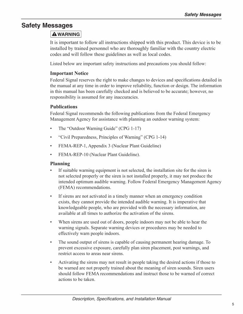
Safety Messages
It is important to follow all instructions shipped with this product. This device is to be installed by trained personnel who are thoroughly familiar with the country electric codes and will follow these guidelines as well as local codes.
Listed below are important safety instructions and precautions you should follow:
Important NoticeFederal Signal reserves the right to make changes to devices and specifications detailed in the manual at any time in order to improve reliability, function or design. The information in this manual has been carefully checked and is believed to be accurate; however, no responsibility is assumed for any inaccuracies.
PublicationsFederal Signal recommends the following publications from the Federal Emergency Management Agency for assistance with planning an outdoor warning system:
• The “Outdoor Warning Guide” (CPG 1-17)
• “Civil Preparedness, Principles of Warning” (CPG 1-14)
• FEMA-REP-1, Appendix 3 (Nuclear Plant Guideline)
• FEMA-REP-10 (Nuclear Plant Guideline).
Planning• If suitable warning equipment is not selected, the installation site for the siren is
not selected properly or the siren is not installed properly, it may not produce the intended optimum audible warning. Follow Federal Emergency Management Agency (FEMA) recommendations.
• If sirens are not activated in a timely manner when an emergency condition exists, they cannot provide the intended audible warning. It is imperative that knowledgeable people, who are provided with the necessary information, are available at all times to authorize the activation of the sirens.
• When sirens are used out of doors, people indoors may not be able to hear the warning signals. Separate warning devices or procedures may be needed to effectively warn people indoors.
• The sound output of sirens is capable of causing permanent hearing damage. To prevent excessive exposure, carefully plan siren placement, post warnings, and restrict access to areas near sirens.
• Activating the sirens may not result in people taking the desired actions if those to be warned are not properly trained about the meaning of siren sounds. Siren users should follow FEMA recommendations and instruct those to be warned of correct actions to be taken.
6
Safety Messages
Modulator High-Powered Omni Speaker (MOD Series)
• After installation, service, or maintenance, test the siren system to confirm that it is operating properly. Test the system regularly to confirm that it will be operational in an emergency.
• If future service and operating personnel do not have these instructions to refer to, the siren system may not provide the intended audible warning and service personnel may be exposed to death, permanent hearing loss, or other bodily injury. File these instructions in a safe place and refer to them periodically. Give a copy of these instructions to new recruits and trainees. Also give a copy to anyone who is going to service or repair the siren.
Installation and Service• Electrocution or severe personal injury can occur when performing various
installation and service functions such as making electrical connections, drilling holes, or lifting equipment. Therefore only experienced electricians should install this product in accordance with national, state and any other electrical codes having jurisdiction. Perform all work under the direction of the installation or service crew safety foreman.
• The sound output of sirens is capable of causing permanent hearing damage. To prevent excessive exposure, carefully plan siren placement, post warnings and restrict access to areas near the sirens. Sirens may be operated from remote control points. Whenever possible, disconnect all siren power including batteries before working near the siren.
• After installation or service, test the siren system to confirm that it is operating properly. Test the system regularly to confirm that it will be operational in an emergency.
• If future service personnel do not have these warnings and all other instructions shipped with the equipment to refer to, the siren system may not provide the intended audible warning and service personnel may be exposed to death, permanent hearing loss, or other bodily injury. File these instructions in a safe place and refer to them periodically. Give a copy of these instructions to new recruits and trainees. Also, give a copy to anyone who is going to service or repair the sirens.
OperationFailure to understand the capabilities and limitations of your siren system could result in permanent hearing loss, other serious injuries or death to persons too close to the sirens when you activate them or to those you need to warn. Carefully read and thoroughly understand all safety notices in this manual and all operations-related-items in all instruction manuals shipped with equipment. Thoroughly discuss all contingency plans with those responsible for warning people in your community, company, or jurisdiction.
Read and understand the information contained in this manual before attempting to install or service the siren.
Pay careful attention to the notice located on the equipment.
7
General Description
Description, Specifications, and Installation Manual
General DescriptionIntroduction
Federal Signal’s Modulator Series siren products are a family of electronic sirens that are capable of producing high intensity warning signals over a large area. The siren consists of a speaker array and a Control/Battery Cabinets. A highly efficient design enables the siren to produce a high sound level, while making moderate demands on the power source.
Modulator models purchased after September, 2017, are preconfigured to support top and side lights kits for visual signaling options that can enhance the proven technology of the Modulator’s intelligible voice communication and signaling.
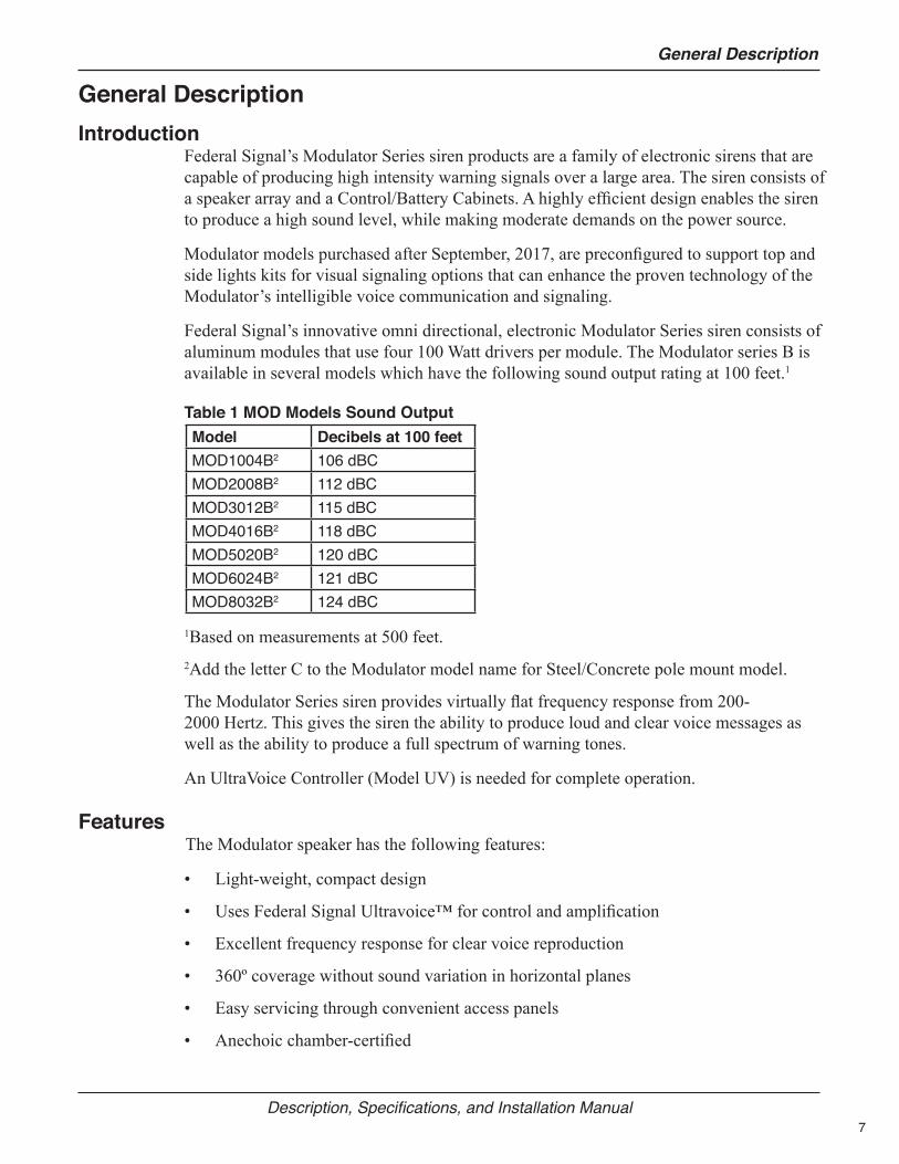
Federal Signal’s innovative omni directional, electronic Modulator Series siren consists of aluminum modules that use four 100 Watt drivers per module. The Modulator series B is available in several models which have the following sound output rating at 100 feet.1
Table 1 MOD Models Sound OutputModel Decibels at 100 feetMOD1004B2 106 dBCMOD2008B2 112 dBCMOD3012B2 115 dBCMOD4016B2 118 dBCMOD5020B2 120 dBCMOD6024B2 121 dBCMOD8032B2 124 dBC
1Based on measurements at 500 feet.2Add the letter C to the Modulator model name for Steel/Concrete pole mount model.
The Modulator Series siren provides virtually flat frequency response from 200-2000 Hertz. This gives the siren the ability to produce loud and clear voice messages as well as the ability to produce a full spectrum of warning tones.
An UltraVoice Controller (Model UV) is needed for complete operation.
FeaturesThe Modulator speaker has the following features:
• Light-weight, compact design
• Uses Federal Signal Ultravoice™ for control and amplification
• Excellent frequency response for clear voice reproduction
• 360º coverage without sound variation in horizontal planes
• Easy servicing through convenient access panels
• Anechoic chamber-certified
8
Specifications
Modulator High-Powered Omni Speaker (MOD Series)
• Optional visual signaling options that enhance the Modulator’s intelligible voice communication and signaling
• New models offer steel/concrete pole mounting solution
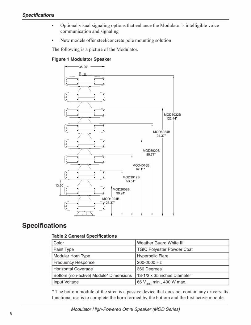
The following is a picture of the Modulator.
Figure 1 Modulator Speaker
MOD1004B26.37"
MOD2008B39.91"
MOD3012B53.51"
MOD4016B67.11"
MOD5020B80.71"
MOD6024B94.37"
MOD8032B122.44"
35.00"
13.60
SpecificationsTable 2 General SpecificationsColor Weather Guard White IIIPaint Type TGIC Polyester Powder CoatModular Horn Type Hyperbolic FlareFrequency Response 200-2000 HzHorizontal Coverage 360 DegreesBottom (non-active) Module* Dimensions 13-1/2 x 35 inches DiameterInput Voltage 66 VRMS min., 400 W max.
* The bottom module of the siren is a passive device that does not contain any drivers. Its functional use is to complete the horn formed by the bottom and the first active module.
9
Specifications
Description, Specifications, and Installation Manual
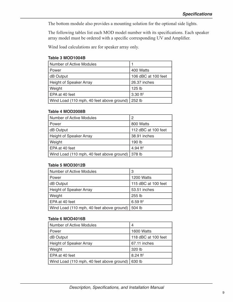
The bottom module also provides a mounting solution for the optional side lights.
The following tables list each MOD model number with its specifications. Each speaker array model must be ordered with a specific corresponding UV and Amplifier.
Wind load calculations are for speaker array only.
Table 3 MOD1004BNumber of Active Modules 1Power 400 WattsdB Output 106 dBC at 100 feetHeight of Speaker Array 26.37 inchesWeight 125 lbEPA at 40 feet 3.30 ft2
Wind Load (110 mph, 40 feet above ground) 252 lb
Table 4 MOD2008BNumber of Active Modules 2Power 800 WattsdB Output 112 dBC at 100 feetHeight of Speaker Array 38.91 inchesWeight 190 lbEPA at 40 feet 4.94 ft2
Wind Load (110 mph, 40 feet above ground) 378 lb
Table 5 MOD3012BNumber of Active Modules 3Power 1200 WattsdB Output 115 dBC at 100 feetHeight of Speaker Array 53.51 inchesWeight 255 lbEPA at 40 feet 6.59 ft2
Wind Load (110 mph, 40 feet above ground) 504 lb
Table 6 MOD4016BNumber of Active Modules 4Power 1600 WattsdB Output 118 dBC at 100 feetHeight of Speaker Array 67.11 inchesWeight 320 lbEPA at 40 feet 8.24 ft2
Wind Load (110 mph, 40 feet above ground) 630 lb
10
Installation
Modulator High-Powered Omni Speaker (MOD Series)
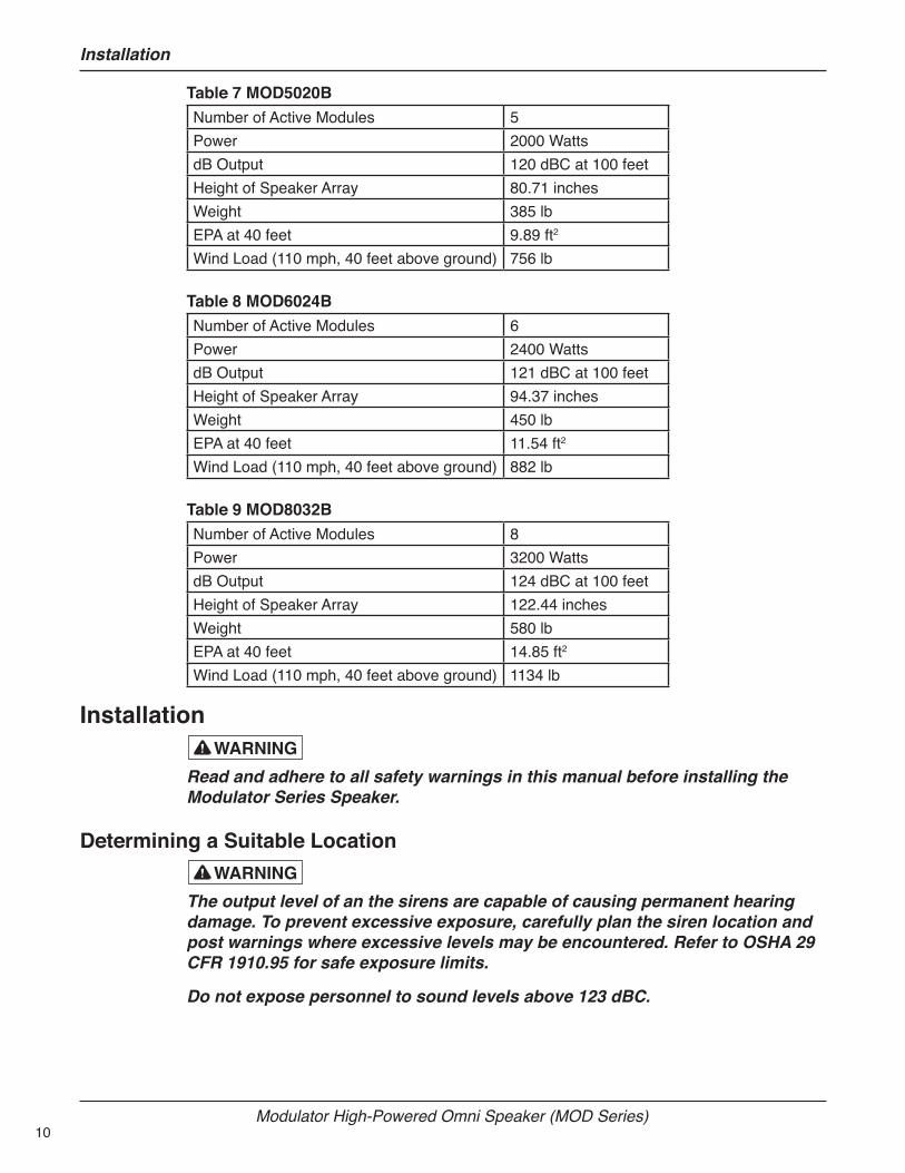
Table 7 MOD5020BNumber of Active Modules 5Power 2000 WattsdB Output 120 dBC at 100 feetHeight of Speaker Array 80.71 inchesWeight 385 lbEPA at 40 feet 9.89 ft2
Wind Load (110 mph, 40 feet above ground) 756 lb
Table 8 MOD6024BNumber of Active Modules 6Power 2400 WattsdB Output 121 dBC at 100 feetHeight of Speaker Array 94.37 inchesWeight 450 lbEPA at 40 feet 11.54 ft2
Wind Load (110 mph, 40 feet above ground) 882 lb
Table 9 MOD8032BNumber of Active Modules 8Power 3200 WattsdB Output 124 dBC at 100 feetHeight of Speaker Array 122.44 inchesWeight 580 lbEPA at 40 feet 14.85 ft2
Wind Load (110 mph, 40 feet above ground) 1134 lb
Installation
Read and adhere to all safety warnings in this manual before installing the Modulator Series Speaker.
Determining a Suitable Location
The output level of an the sirens are capable of causing permanent hearing damage. To prevent excessive exposure, carefully plan the siren location and post warnings where excessive levels may be encountered. Refer to OSHA 29 CFR 1910.95 for safe exposure limits.
Do not expose personnel to sound levels above 123 dBC.
11
Installation
Description, Specifications, and Installation Manual
Careful consideration of the factors affecting the propagation of sound from the siren and the response of the human ear to the sound will optimize the ability of the siren to effectively warn the community. Follow Federal Emergency Management Agency (FEMA) guidelines when designing the warning system.
The reduction of signal intensity, as the distance from the siren increases and the minimum desired signal level at the fringe of the area to be covered are important considerations when choosing a siren installation site. As the distance from the siren increases, sound level losses accumulate. These losses are a result of weather conditions, the terrain, obstructions in the sound path, the pitch of the sound and the height of the siren.
Optimum sound propagation conditions occur when no obstructions exist in the sound path, the terrain is hard and flat, and the air is blowing away from the source. Under these conditions, you can expect a 6 dB loss per distance doubled. A loss per distance doubled of 10 dB is typically experienced because atmosphere is rarely calm, terrain may not be flat, and buildings or other obstructions are frequently present in the sound path.
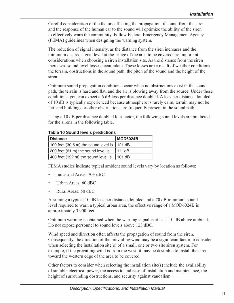
Using a 10 dB per distance doubled loss factor, the following sound levels are predicted for the sirens in the following table.
Table 10 Sound levels predictionsDistance MOD6024B100 feet (30.5 m) the sound level is 121 dB200 feet (61 m) the sound level is 111 dB400 feet (122 m) the sound level is 101 dB
FEMA studies indicate typical ambient sound levels vary by location as follows:
• Industrial Areas: 70+ dBC
• Urban Areas: 60 dBC
• Rural Areas: 50 dBC
Assuming a typical 10 dB loss per distance doubled and a 70 dB minimum sound level required to warn a typical urban area, the effective range of a MOD6024B is approximately 3,900 feet.
Optimum warning is obtained when the warning signal is at least 10 dB above ambient. Do not expose personnel to sound levels above 123 dBC.
Wind speed and direction often affects the propagation of sound from the siren. Consequently, the direction of the prevailing wind may be a significant factor to consider when selecting the installation site(s) of a small, one or two site siren system. For example, if the prevailing wind is from the west, it may be desirable to install the siren toward the western edge of the area to be covered.
Other factors to consider when selecting the installation site(s) include the availability of suitable electrical power, the access to and ease of installation and maintenance, the height of surrounding obstructions, and security against vandalism.
12
Installation
Modulator High-Powered Omni Speaker (MOD Series)
Installing the Sirens
Electrocution or severe personal injury can occur when making electrical connections, drilling holes, or lifting equipment. Therefore, experienced electricians in accordance with national and local electrical codes, acting under the direction of the installation crew safety foreman, should perform installation.
Most siren installations are one of two types: Pole Mount or Flat Surface Mount. These two configurations make it possible to install a siren in almost any situation. If the installations in this section are not suitable, modification of one of the configurations may be practical.
A siren is typically installed 40 to 50 feet above the ground. If the installation is located less than 40 feet above the ground, the sound intensity at close range may increase, but at the same time the effective range of the siren may be reduced. Conversely, if the siren is located more than 50 feet above ground, the effective range of the siren may increase, but the sound may skip over areas closer to the siren. These variables may make it desirable to test the sound coverage of the siren at various heights and locations whenever possible.
NOTE: To protect the speaker arrays from damage during shipping, all models have been shipped without drivers installed.
Connecting the Driver WiresAfter uncrating the siren, connect the driver wires:
1. Remove the four (4) inspection doors from each individual active module by removing the four (4) bolt and washer sets of each door. Note the position of the flat washer and lock washer.
2. The drivers should be threaded clockwise onto the horn throats.
3. Hand tighten approximately 1/2 turn after gasket engagement.
4. Locate the two (2) wires tie wrapped near the end of the horn throat. Note the label on the back of the drivers and connect the solid wire to terminal 1 and the striped wire to terminal 2 and white jumpers from 1 to 2 as shown in Figures 6 and 7. Driver Orientation.
Connecting driver wires out of phase may cause severe reduction in sound output.
Wooden Pole MountingA typical wooden pole-mounted siren installation is shown in Figure 2. The siren is mounted on a Class 2 utility pole (ANSI type wooden pole or equivalent) with a minimum horizontal ground stress rating of 3,700 pounds (1682 kg). Insure that soil loads will conform to this size utility pole. It is attached to the pole by means of legs, as shown in Figure 3.

13
Installation
Description, Specifications, and Installation Manual
Figure 2 Typical Wooden Pole-mounted Installation
REFER TO
REFER TOCONTRACTSPECS.
CONTRACT SPEC.
(CUSTOMER SUPPLIED)
GROUND LEVEL
CONCRETE FOOTING OPTIONALCONTRACT SPECIFICATIONS DETERMINE
AND NATIONAL ELECTRICAL BUILDING CODESBEFORE PROCEEDING WITH INSTALLATION.
INSTALLATION ALWAYS REFER TO LOCALNOTE: DRAWING DEPICTS A TYPICAL
NOTE: CERTAIN SOIL CONDITIONS MAYREQUIRE GUYING FOR THE POLE.
CLASS II UTILITY POLE(CUSTOMER SUPPLIED)
(CUSTOMER SUPPLIED)
GROUND ROD TO BE 8 FT.#4 COPPER WITH CLAMP
1-1/4" CRANE LIFT HOLE(CONTROL UNIT & BATTERY BOX)
ULTRAVOICE CONTROL
CONTROL UNIT GROUND WIRE
BATTERY BOX
SERVICE DISCONNECT
BETWEEN ANGLE LEGS & POLE.
(CUSTOMER SUPPLIED)
(CUSTOMER SUPPLIED)(IF REQUIRED)
INSTALL 5/8" LAG BOLTS & SHIMS(CUSTOMER SUPPLIED) AS REQUIRED
SPEAKER ASSEMBLY GROUNDWIRE, #4 COPPER, CONNECT
RADIO ANTENNA (IF REQ'D)
TO GROUND ROD DIRECTLY.
CONDUIT & CLAMPS(CUSTOMER SUPPLIED)
40' SPEAKER CABLE (LONGER OPTIONAL) (FEDERAL SUPPLIED)
CRANE LIFT EYEBOLT
100W DRIVER (4 PER ACTIVE CELL)
(SHOWN POLE MOUNTED)MOD6024
DRIVER ACCESS DOOR
291275B

14
Installation
Modulator High-Powered Omni Speaker (MOD Series)
Figure 3 Siren Leg Assembly
1/2-13 HEX NUTS (8)
SPLIT LOCKWASHERS (8)
1/2-13 HEX HD. BOLTS (8)
LEGS (4)
MODULATOR SIRENBASE PLATE
LEGS (4)SEE DETAIL
BELOW
291274A
RUBBERINSULATOR
8570081
Using the 3 feet. long angle iron legs, the siren is mounted on the Class 2 utility pole as follows:
1. Uncrate the siren and remove the nuts that hold the siren on the shipping base. Install drivers if needed. Lift the siren approximately 3-1/2 feet with a crane or hoist.
NOTE: To protect the speaker arrays from damage during shipping, all models have been shipped without drivers installed.
2. If you ordered optional top and side lights, see Installing Lights on the Siren. You may want to install lights prior to placing onto poll.
3. Install the four legs on the siren mounting plate, as shown in Figure 3. Use two stainless steel 1/2-inch bolts, nuts and lock washers (provided) for each leg. All mounting hardware needed is supplied in the hardware kit shipped with this manual. Do not tighten the bolts completely.
The eyebolt does NOT have sufficient strength to support the combined weight of the siren and a utility pole. Therefore, do NOT attempt to erect the pole and siren together using the eyebolt as a lifting point.
15
Installation
Description, Specifications, and Installation Manual
4. Erect the utility pole in accordance with accepted practices and FEMA guidelines (refer to warning). Be sure the pole extends at least 40 feet above the ground.
5. Raise the siren to the necessary height, and lower it over the pole. Maintain tension on lifting chain until all bolts are tightened.
6. Adjust the legs and insert shims, if necessary, between the siren legs and pole. Bolt the siren to the pole using two user supplied 5/8 in lag bolts, at least four inches long for each leg. Tighten all bolts, including those from step 2.
Steel Pole MountingIn a typical steel pole-mounted siren installation the MOD1004BC, MOD2008BC and MOD3012BC sirens are mounted on a Grade A Standard galvanized steel pole. The MOD4016BC, MOD5020BC, MOD6024BC, and MOD8032BC are mounted on a Grade A Heavy galvanized steel pole. (Insure that soil loads will conform to this size utility pole).
NOTE: The siren leg assembly is not included with the steel/concrete pole models.
1. Erect the steel utility pole in accordance with accepted practices and FEMA guidelines.
2. Uncrate the siren. Remove and dispose of any hardware that holds the siren on the shipping base. Install drivers (see NOTE on previous page). Lift the siren with a crane or hoist to the necessary height and lower it over the pole. Maintain tension on lifting chain until all bolts are tightened.
3. If you ordered optional top and side lights, see Installing Lights on the Siren. You may want to install lights prior to placing onto poll.
NOTE: Siren cable is run through the center of the mounting plate through the steel pole. Siren cable can be pre-assembled through center of mounting plate for no conduit install.
The eyebolt does NOT have sufficient strength to support the combined weight of the siren and a utility pole. Therefore, do NOT attempt to erect the pole and siren together using the eyebolt as a lifting point.
16
Installation
Modulator High-Powered Omni Speaker (MOD Series)
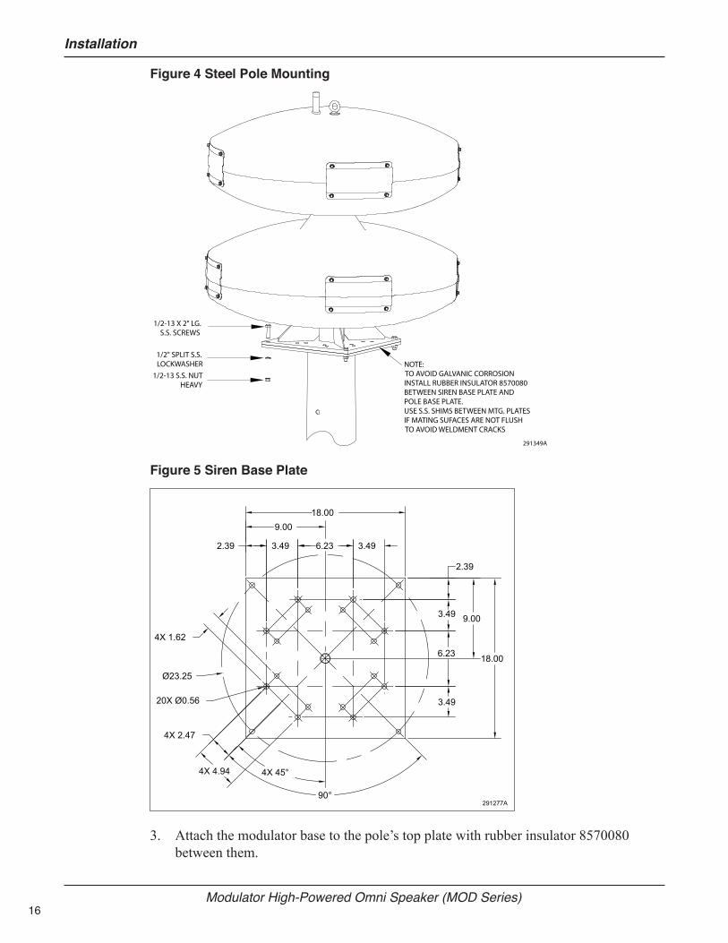
Figure 4 Steel Pole Mounting
1/2-13 X 2" LG. S.S. SCREWS
1/2" SPLIT S.S.LOCKWASHER
1/2-13 S.S. NUTHEAVY
NOTE:TO AVOID GALVANIC CORROSIONINSTALL RUBBER INSULATOR 8570080BETWEEN SIREN BASE PLATE ANDPOLE BASE PLATE.USE S.S. SHIMS BETWEEN MTG. PLATESIF MATING SUFACES ARE NOT FLUSHTO AVOID WELDMENT CRACKS
291349A
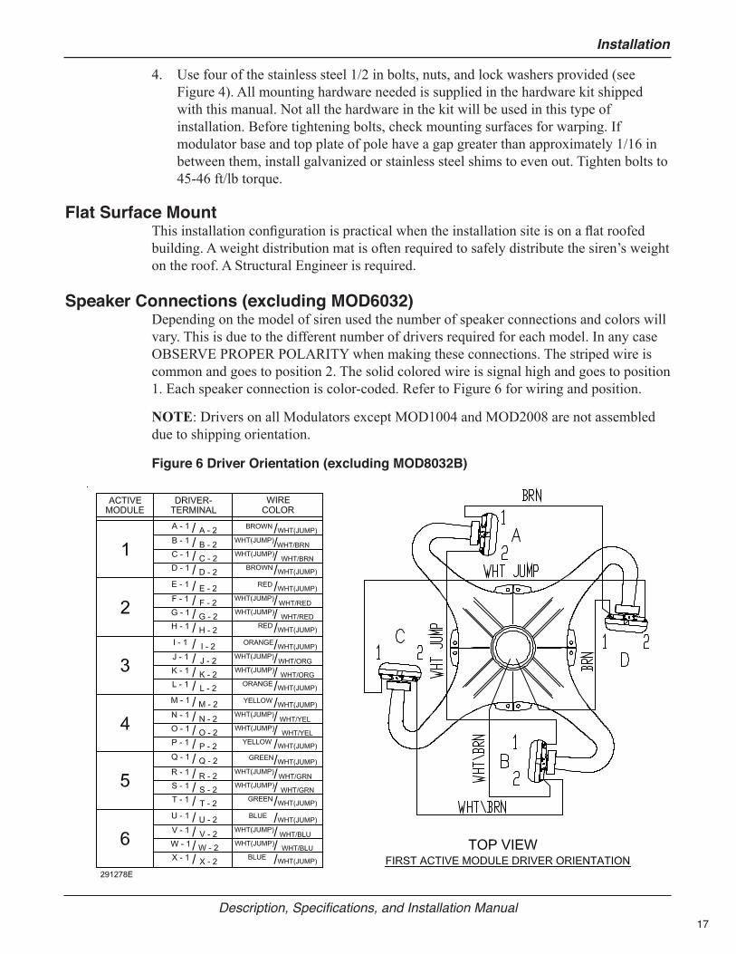
Figure 5 Siren Base Plate
291277A
3.49
9.00
3.49
3.49
2.39
18.00
90°
4X 1.62
4X 45°
4X 2.47
4X 4.94
2.39
9.00
6.233.49
18.006.23
Ø23.25
20X Ø0.56
3. Attach the modulator base to the pole’s top plate with rubber insulator 8570080 between them.
17
Installation
Description, Specifications, and Installation Manual
4. Use four of the stainless steel 1/2 in bolts, nuts, and lock washers provided (see Figure 4). All mounting hardware needed is supplied in the hardware kit shipped with this manual. Not all the hardware in the kit will be used in this type of installation. Before tightening bolts, check mounting surfaces for warping. If modulator base and top plate of pole have a gap greater than approximately 1/16 in between them, install galvanized or stainless steel shims to even out. Tighten bolts to 45-46 ft/lb torque.
Flat Surface MountThis installation configuration is practical when the installation site is on a flat roofed building. A weight distribution mat is often required to safely distribute the siren’s weight on the roof. A Structural Engineer is required.
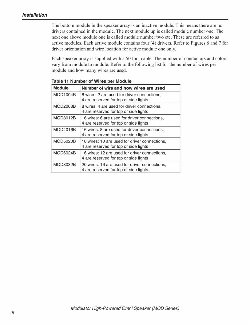
Speaker Connections (excluding MOD6032)Depending on the model of siren used the number of speaker connections and colors will vary. This is due to the different number of drivers required for each model. In any case OBSERVE PROPER POLARITY when making these connections. The striped wire is common and goes to position 2. The solid colored wire is signal high and goes to position 1. Each speaker connection is color-coded. Refer to Figure 6 for wiring and position.
NOTE: Drivers on all Modulators except MOD1004 and MOD2008 are not assembled due to shipping orientation.
Figure 6 Driver Orientation (excluding MOD8032B)
18
Installation
Modulator High-Powered Omni Speaker (MOD Series)
The bottom module in the speaker array is an inactive module. This means there are no drivers contained in the module. The next module up is called module number one. The next one above module one is called module number two etc. These are referred to as active modules. Each active module contains four (4) drivers. Refer to Figures 6 and 7 for driver orientation and wire location for active module one only.
Each speaker array is supplied with a 50 foot cable. The number of conductors and colors vary from module to module. Refer to the following list for the number of wires per module and how many wires are used.
Table 11 Number of Wires per ModuleModule Number of wire and how wires are usedMOD1004B 8 wires: 2 are used for driver connections,
4 are reserved for top or side lightsMOD2008B 8 wires: 4 are used for driver connections,
4 are reserved for top or side lightsMOD3012B 16 wires: 6 are used for driver connections,
4 are reserved for top or side lightsMOD4016B 16 wires: 8 are used for driver connections,
4 are reserved for top or side lightsMOD5020B 16 wires: 10 are used for driver connections,
4 are reserved for top or side lightsMOD6024B 16 wires: 12 are used for driver connections,
4 are reserved for top or side lightsMOD8032B 20 wires: 16 are used for driver connections,
4 are reserved for top or side lights.
19
Installation
Description, Specifications, and Installation Manual
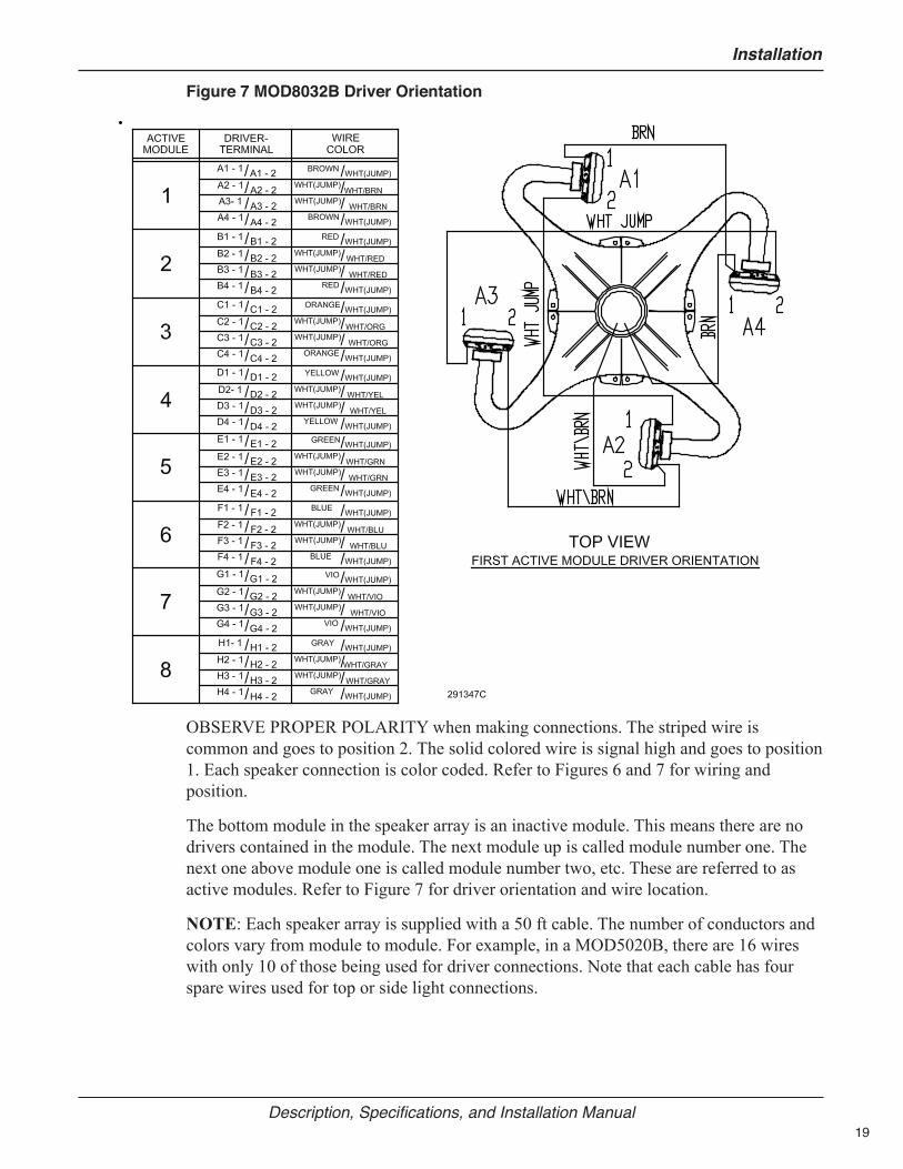
Figure 7 MOD8032B Driver Orientation
OBSERVE PROPER POLARITY when making connections. The striped wire is common and goes to position 2. The solid colored wire is signal high and goes to position 1. Each speaker connection is color coded. Refer to Figures 6 and 7 for wiring and position.
The bottom module in the speaker array is an inactive module. This means there are no drivers contained in the module. The next module up is called module number one. The next one above module one is called module number two, etc. These are referred to as active modules. Refer to Figure 7 for driver orientation and wire location.
NOTE: Each speaker array is supplied with a 50 ft cable. The number of conductors and colors vary from module to module. For example, in a MOD5020B, there are 16 wires with only 10 of those being used for driver connections. Note that each cable has four spare wires used for top or side light connections.
20
Installation
Modulator High-Powered Omni Speaker (MOD Series)
Installing Lights on the SirenModulator models can be ordered with optional top lights and/or side lights. If not ordered with the Modulator siren, they can be added later by purchasing the Top Light Kit (Federal Signal part number 191XL-024R) or Side Light Kit (Federal Signal part number MOD-QF-KIT). Modulator models purchased after September, 2017, are preconfigured to support Top Light and Side Light Kits.
NOTE: The standard light referenced is the color red, but other colors are available.
The following instructions refer to the configuration of the Modulators that have been preconfigured.
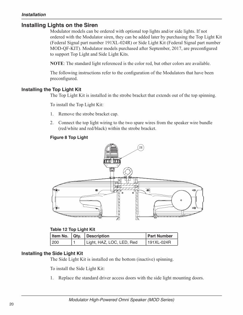
Installing the Top Light KitThe Top Light Kit is installed in the strobe bracket that extends out of the top spinning.
To install the Top Light Kit:
1. Remove the strobe bracket cap.
2. Connect the top light wiring to the two spare wires from the speaker wire bundle (red/white and red/black) within the strobe bracket.
Figure 8 Top Light
Table 12 Top Light KitItem No. Qty. Description Part Number200 1 Light, HAZ, LOC, LED, Red 191XL-024R
Installing the Side Light KitThe Side Light Kit is installed on the bottom (inactive) spinning.
To install the Side Light Kit:
1. Replace the standard driver access doors with the side light mounting doors.
21
Installation
Description, Specifications, and Installation Manual
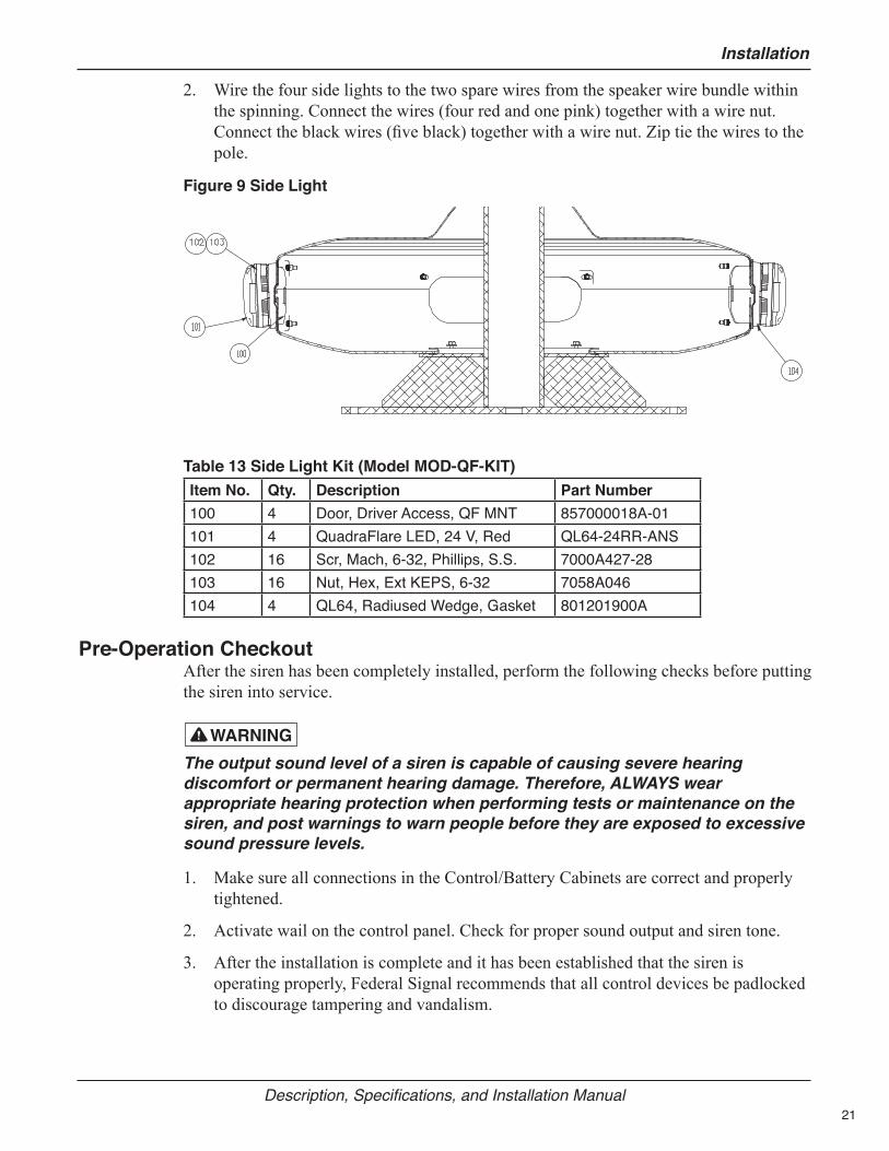
2. Wire the four side lights to the two spare wires from the speaker wire bundle within the spinning. Connect the wires (four red and one pink) together with a wire nut. Connect the black wires (five black) together with a wire nut. Zip tie the wires to the pole.
Figure 9 Side Light
Table 13 Side Light Kit (Model MOD-QF-KIT)Item No. Qty. Description Part Number100 4 Door, Driver Access, QF MNT 857000018A-01101 4 QuadraFlare LED, 24 V, Red QL64-24RR-ANS102 16 Scr, Mach, 6-32, Phillips, S.S. 7000A427-28103 16 Nut, Hex, Ext KEPS, 6-32 7058A046104 4 QL64, Radiused Wedge, Gasket 801201900A
Pre-Operation CheckoutAfter the siren has been completely installed, perform the following checks before putting the siren into service.
The output sound level of a siren is capable of causing severe hearing discomfort or permanent hearing damage. Therefore, ALWAYS wear appropriate hearing protection when performing tests or maintenance on the siren, and post warnings to warn people before they are exposed to excessive sound pressure levels.
1. Make sure all connections in the Control/Battery Cabinets are correct and properly tightened.
2. Activate wail on the control panel. Check for proper sound output and siren tone.
3. After the installation is complete and it has been established that the siren is operating properly, Federal Signal recommends that all control devices be padlocked to discourage tampering and vandalism.

22
Maintenance
Modulator High-Powered Omni Speaker (MOD Series)
Maintenance
Service or maintenance should be performed by qualified personnel familiar with the siren, associated controls, and power sources being used.
The sound output of the siren is capable of causing permanent hearing damage. Use adequate hearing protection and avoid excessive exposure.
Before servicing or maintaining, ensure that remote activation cannot occur and disconnect power to the siren and its controls.
The output level of a Modulator Series Siren is capable of causing permanent hearing damage. Therefore, ALWAYS wear hearing protection when performing tests or maintenance on the siren.
To prevent the siren from sounding always turn off the power to the siren at the disconnect switch and remove any DC power being supplied by the battery box before inspecting or maintaining the siren.
Test the siren for proper operation at least once a month. A daily test at noon, curfew, or other selected time is preferred. This not only enhances the usefulness of the siren and verifies that it remains ready for use in an emergency, but instills public confidence in the reliability of the warning system.
In order to minimize the possibility of siren failure, annual inspection and maintenance is desirable.
Perform a driver inspection as described in the next section.
Replacing the DriverTo determine if a driver is defective, refer to the procedure outlined in the installation instruction for the amplifier control unit or remove the speaker circuit from the terminal block and measure the impedance of the circuit. The impedance of each 400 W cell of the siren will measure approximately 4.5 ohms. If the reading is higher, (9 ohms), one driver is bad. If the circuit is open, then either multiple drivers are bad or a wire has been severed. The impedance of a single driver should be 2.25 ohms.
To determine the location of the bad driver refer to Figures 6 and 7.
To replace a defective driver:
1. Remove the four hex head 1/4 inch mounting bolts that are holding the inspection plate. Make sure the flat washer and split washer are not misplaced. Note the color and location of the wires going to the driver.
2. Remove the wire from the terminals on the driver.
3. Remove the driver by turning it counterclockwise.

23
Parts Lists
Description, Specifications, and Installation Manual
4. Add new driver by turning it clockwise.
5. Make sure that the male threads are greased.
6. Reconnect the wires as previously noted.
Parts ListsTable 14 MOD 1004B Parts ListItem Number Quantity Description150A146A 4.0000 TIE WRAP, 8" LG,UV STABILIZED161693A 2.0000 DECAL, LABL, FS LOGO161A507A 2.0000 LABEL, WARNING, HEARING LOS17501517A-50 1.0000 CABLE, SPKR.MOD1004B/25500059A 1.0000 MANUAL, MODULATOR, SERIES B2561043A .0000 SHT., MOD SRN. CHECK LIST7000A338-88 2.0000 SCREW,1/2-13 HEX HD.7000A345-16 36.0000 SCREW, MACH HEX HD 1/4-207003A000-24 1.0000 EYEBOLT,1/2-13,STL,1.50"7004A004-32 2.0000 BOLT, CRG RD HD STL 3/8-167004A004-56 6.0000 BOLT, CRG STL 3/8-16 X 3-17057A032 8.0000 NUT, HEX DBL CHAM STL7058A010 8.0000 NUT, EL STOP HEX LT SS7059A077 2.0000 NUT, HEX, STL,CAD,1/2-137065A049A 20.0000 RIVNUT, 1/4-207072A024 44.0000 WASH, FLT, SS, .266 X 11/167072A036 8.0000 WASHER, FLAT 3/8 IN. NOM I7072A038 1.0000 WASH, FLT, RBR, .9/16 X 1-3/47072A095 1.0000 WASH, FLT, STL, 1/2 X 1-3/47072A148A 4.0000 WASH, FLT NEOPRENE 5/8 OD7074A025 2.0000 LKWASH, SPLIT STL 1/2 SCR7074A067 32.0000 LKWASHER, SPLIT, SS7099A103-15 2.0000 RIVET, POP, ALUM,1/8HD, .26581461331A-14 1.0000 NAMEPLATE, MOD1004B8283A452 4.0000 WASHER, RUBBER8291B016 1.0000 BAG, POLY, RL,14 X 16857000011A 1.0000 SPIN, TOP, MACH'D857000012A-01 1.0000 SPIN, FEMALE, MACH'D, BOTTOM857000013A 1.0000 SPIN, MALE, MACH'D857000013A-01 1.0000 SPIN, MALE, MACH'D, BOTTOM857000017A-01 1.0000 PIPE, WELDMENT, MOD1004B857000018A 4.0000 DOOR, ACCESS WHT857000034A 4.0000 HORN THROAT ASSY857000057A-01 .0000 FINAL ASSY.MOD1004B

24
Parts Lists
Modulator High-Powered Omni Speaker (MOD Series)
Item Number Quantity Description8570010C 1.0000 SCREEN, HORN, MOD28570011A 2.0000 GASKET, U, SPINNING857000123A 4.0000 GASKET, SPINNING8570026A 4.0000 RUBBER PAD 2 X 1 X. 068570053A-01 1.0000 BRKT, ASSY, SIREN LIFTING8570081A 4.0000 INSULATOR, SIREN LEGR42-04-01 11.6700 GASKET, DOOR, .38 X.25R70-08-03 1.2500 ADHESIVE, RTV 6708R72-02-01 .0100 LOCTITE,#271 HIGH STRENGTR81-11-01 .0400 GREASE, NTOGEL, 759G, ELEC.CT300214-09-009 2.0000 T-WIRE, 48" (5/16NT:5/16NT)78000069A 1.0000 PALLET, 38" X 35"78000107A 1.0000 SKID, TOP, 38" X 35"8549A083A 1.0000 ACCY KIT, MTG HDW, 6128549A170A 4.0000 BRACKET ASSY, POLE MOUNTI8570063A 4.0000 100 W NEO DRIVER
Table 15 MOD 2008B Parts ListItem Number Quantity Description150A146A 8.0000 TIE WRAP, 8" LG,UV STABILIZED161693A 2.0000 DECAL, LABL, FS LOGO161A507A 2.0000 LABEL, WARNING, HEARING LOS17501517A-50 1.0000 CABLE, SPKR.MOD1004B/25500059A 1.0000 MANUAL, MODULATOR, SERIES B2561043A .0000 SHT., MOD SRN.CHECK LIST7000A338-88 2.0000 SCREW, 1/2-13 HEX HD.7000A345-16 64.0000 SCREW, MACH HEX HD 1/4-207003A000-24 1.0000 EYEBOLT,1/2-13, STL,1.50"7004A004-32 2.0000 BOLT, CRG RD HD STL 3/8-167004A004-56 6.0000 BOLT, CRG STL 3/8-16 X 3-17057A032 8.0000 NUT, HEX DBL CHAM STL7058A010 16.0000 NUT, EL STOP HEX LT SS7059A077 2.0000 NUT, HEX, STL,CAD,1/2-137065A049A 36.0000 RIVNUT, 1/4-207072A024 80.0000 WASH, FLT, SS, .266 X 11/167072A036 8.0000 WASHER, FLAT 3/8 IN. NOM I7072A038 1.0000 WASH, FLT, RBR, .9/16 X 1-3/47072A095 1.0000 WASH, FLT, STL,1/2 X 1-3/47072A148A 8.0000 WASH, FLT NEOPRENE 5/8 OD7074A025 2.0000 LKWASH, SPLIT STL 1/2 SCR7074A067 48.0000 LKWASHER, SPLIT, SS

25
Parts Lists
Description, Specifications, and Installation Manual
Item Number Quantity Description7099A103-15 2.0000 RIVET, POP, ALUM,1/8HD, .26581461331A-15 1.0000 NAMEPLATE, MOD2008B8283A452 8.0000 WASHER, RUBBER8291B016 1.0000 BAG, POLY, RL,14 X 16857000011A 1.0000 SPIN, TOP, MACH'D857000012A 1.0000 SPIN, FEMALE, MACH'D857000012A-01 1.0000 SPIN, FEMALE, MACH'D, BOTTOM857000013A 2.0000 SPIN, MALE, MACH'D857000013A-01 1.0000 SPIN, MALE, MACH'D, BOTTOM857000017A-02 1.0000 PIPE, WELDMENT, MOD2008B857000018A 8.0000 DOOR, ACCESS WHT857000034A 8.0000 HORN THROAT ASSY857000057A-02 .0000 FINAL ASSY.MOD2008B857000123A 8.0000 GASKET, SPINNING8570010C 2.0000 SCREEN, HORN, MOD28570011A 2.0000 GASKET, U, SPINNING8570026A 8.0000 RUBBER PAD 2 X 1 X .068570053A-01 1.0000 BRKT, ASSY, SIREN LIFTING8570081A 4.0000 INSULATOR, SIREN LEGR42-04-01 23.3400 GASKET, DOOR, .38 X.25R70-08-03 2.5000 ADHESIVE, RTV 6708R72-02-01 .0100 LOCTITE, #271 HIGH STRENGTR81-11-01 .0600 GREASE, NTOGEL, 759G, ELEC.CT300214-09-009 4.0000 T-WIRE, 48" (5/16NT:5/16NT)78000069A 1.0000 PALLET, 38" X 35"78000107A 1.0000 SKID, TOP, 38" X 35"8549A083A 1.0000 ACCY KIT, MTG HDW, 6128549A170A 4.0000 BRACKET ASSY, POLE MOUNTI8570063A 8.0000 100W NEO DRIVER
Table 16 MOD 3012B Parts ListItem Number Quantity Description150A146A 12.0000 TIE WRAP, 8" LG, UV STABILIZED161693A 2.0000 DECAL, LABL, FS LOGO161A507A 2.0000 LABEL, WARNING, HEARING LOS17501518A-52 1.0000 CABLE, SPKR.MOD3012B THRU25500059A 1.0000 MANUAL, MODULATOR, SERIES B2561043A .0000 SHT., MOD SRN.CHECK LIST7000A338-88 2.0000 SCREW, 1/2-13 HEX HD.7000A345-16 92.0000 SCREW, MACH HEX HD 1/4-207003A000-24 1.0000 EYEBOLT,1/2-13, STL,1.50"

26
Parts Lists
Modulator High-Powered Omni Speaker (MOD Series)
Item Number Quantity Description7004A004-32 2.0000 BOLT, CRG RD HD STL 3/8-167004A004-56 6.0000 BOLT, CRG STL 3/8-16 X 3-17057A032 8.0000 NUT,HEX DBL CHAM STL7058A010 24.0000 NUT, EL STOP HEX LT SS7059A077 2.0000 NUT, HEX, STL, CAD, 1/2-137065A049A 52.0000 RIVNUT, 1/4-207072A024 116.0000 WASH, FLT, SS, .266 X 11/167072A036 8.0000 WASHER, FLAT 3/8 IN. NOM I7072A038 1.0000 WASH, FLT, RBR,.9/16 X 1-3/47072A095 1.0000 WASH, FLT, STL,1/2 X 1-3/47072A148A 12.0000 WASH, FLT NEOPRENE 5/8 OD7074A025 2.0000 LKWASH, SPLIT STL 1/2 SCR7074A067 80.0000 LKWASHER, SPLIT, SS7099A103-15 2.0000 RIVET, POP, ALUM, 1/8 HD, .26581461331A-16 1.0000 NAMEPLATE, MOD3012B8283A452 12.0000 WASHER, RUBBER8291B016 1.0000 BAG, POLY, RL,14 X 16857000011A 1.0000 SPIN, TOP, MACH'D857000012A 2.0000 SPIN, FEMALE, MACH'D857000012A-01 1.0000 SPIN, FEMALE, MACH'D, BOTTOM857000013A 3.0000 SPIN, MALE, MACH'D857000013A-01 1.0000 SPIN, MALE, MACH'D, BOTTOM857000017A-03 1.0000 PIPE, WELDMENT, MOD3012B857000018A 12.0000 DOOR, ACCESS WHT857000034A 12.0000 HORN THROAT ASSY857000057A-03 .0000 FINAL ASSY.MOD3012B857000123A 12.0000 GASKET, SPINNING8570010C 3.0000 SCREEN, HORN, MOD28570011A 2.0000 GASKET, U, SPINNING8570026A 12.0000 RUBBER PAD 2 X 1 X .068570053A-01 1.0000 BRKT, ASSY, SIREN LIFTING8570081A 4.0000 INSULATOR, SIREN LEGR42-04-01 35.0000 GASKET, DOOR, .38 X .25R70-08-03 3.7500 ADHESIVE, RTV 6708R72-02-01 .0100 LOCTITE, #271 HIGH STRENGTR81-11-01 .0600 GREASE, NTOGEL, 759G, ELEC.CT300214-09-009 6.0000 T-WIRE, 48" (5/16NT:5/16NT)78000069A 1.0000 PALLET, 38" X 35"78000107A 1.0000 SKID, TOP, 38" X 35"8549A083A 1.0000 ACCY KIT, MTG HDW, 6128549A170A 4.0000 BRACKET ASSY, POLE MOUNTI
27
Parts Lists
Description, Specifications, and Installation Manual
Item Number Quantity Description8570063A 12.0000 100 W NEO DRIVER
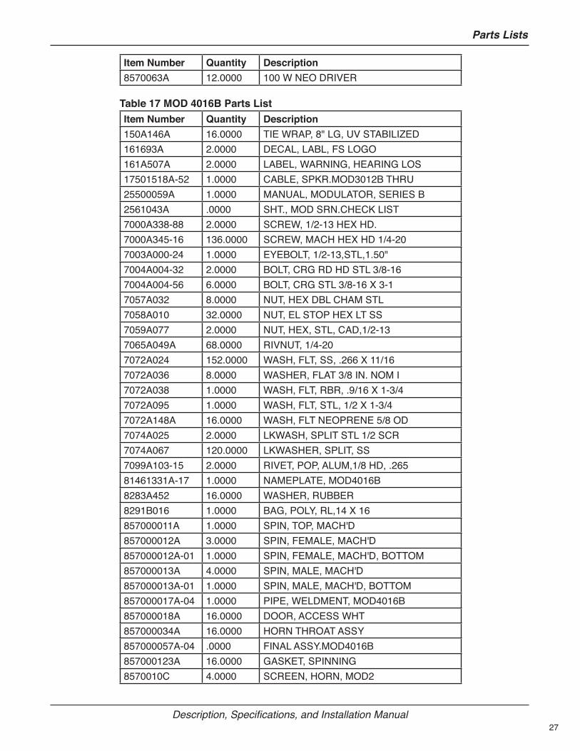
Table 17 MOD 4016B Parts ListItem Number Quantity Description150A146A 16.0000 TIE WRAP, 8" LG, UV STABILIZED161693A 2.0000 DECAL, LABL, FS LOGO161A507A 2.0000 LABEL, WARNING, HEARING LOS17501518A-52 1.0000 CABLE, SPKR.MOD3012B THRU25500059A 1.0000 MANUAL, MODULATOR, SERIES B2561043A .0000 SHT., MOD SRN.CHECK LIST7000A338-88 2.0000 SCREW, 1/2-13 HEX HD.7000A345-16 136.0000 SCREW, MACH HEX HD 1/4-207003A000-24 1.0000 EYEBOLT, 1/2-13,STL,1.50"7004A004-32 2.0000 BOLT, CRG RD HD STL 3/8-167004A004-56 6.0000 BOLT, CRG STL 3/8-16 X 3-17057A032 8.0000 NUT, HEX DBL CHAM STL7058A010 32.0000 NUT, EL STOP HEX LT SS7059A077 2.0000 NUT, HEX, STL, CAD,1/2-137065A049A 68.0000 RIVNUT, 1/4-207072A024 152.0000 WASH, FLT, SS, .266 X 11/167072A036 8.0000 WASHER, FLAT 3/8 IN. NOM I7072A038 1.0000 WASH, FLT, RBR, .9/16 X 1-3/47072A095 1.0000 WASH, FLT, STL, 1/2 X 1-3/47072A148A 16.0000 WASH, FLT NEOPRENE 5/8 OD7074A025 2.0000 LKWASH, SPLIT STL 1/2 SCR7074A067 120.0000 LKWASHER, SPLIT, SS7099A103-15 2.0000 RIVET, POP, ALUM,1/8 HD, .26581461331A-17 1.0000 NAMEPLATE, MOD4016B8283A452 16.0000 WASHER, RUBBER8291B016 1.0000 BAG, POLY, RL,14 X 16857000011A 1.0000 SPIN, TOP, MACH'D857000012A 3.0000 SPIN, FEMALE, MACH'D857000012A-01 1.0000 SPIN, FEMALE, MACH'D, BOTTOM857000013A 4.0000 SPIN, MALE, MACH'D857000013A-01 1.0000 SPIN, MALE, MACH'D, BOTTOM857000017A-04 1.0000 PIPE, WELDMENT, MOD4016B857000018A 16.0000 DOOR, ACCESS WHT857000034A 16.0000 HORN THROAT ASSY857000057A-04 .0000 FINAL ASSY.MOD4016B857000123A 16.0000 GASKET, SPINNING8570010C 4.0000 SCREEN, HORN, MOD2

28
Parts Lists
Modulator High-Powered Omni Speaker (MOD Series)
Item Number Quantity Description8570011A 2.0000 GASKET, U, SPINNING8570026A 16.0000 RUBBER PAD 2 X 1 X .068570053A-01 1.0000 BRKT, ASSY, SIREN LIFTING8570081A 4.0000 INSULATOR,SIREN LEGR42-04-01 46.6800 GASKET, DOOR, .38 X .25R70-08-03 5.0000 ADHESIVE, RTV 6708R72-02-01 .0100 LOCTITE, #271 HIGH STRENGTR81-11-01 .1600 GREASE, NTOGEL, 759G, ELEC.CT300214-09-009 4.0000 T-WIRE, 48" (5/16NT:5/16NT)78000069A 1.0000 PALLET, 38" X 35"78000070A 2.0000 SADDLE, FOAM, MOD278000107A 1.0000 SKID, TOP, 38" X 35"8549A083A 1.0000 ACCY KIT, MTG HDW, 6128549A170A 4.0000 BRACKET ASSY, POLE MOUNTI8570063A 16.0000 100W NEO DRIVER
Table 18 MOD 5020B Parts ListItem Number Quantity Description150A146A 20.0000 TIE WRAP,8" LG, UV STABILIZED161693A 2.0000 DECAL, LABL, FS LOGO161A507A 2.0000 LABEL, WARNING, HEARING LOS17501518A-52 1.0000 CABLE, SPKR.MOD3012B THRU25500059A 1.0000 MANUAL, MODULATOR, SERIES B2561043A .0000 SHT., MOD SRN.CHECK LIST7000A338-88 2.0000 SCREW,1/2-13 HEX HD.7000A345-16 148.0000 SCREW, MACH HEX HD 1/4-207003A000-24 1.0000 EYEBOLT,1/2-13, STL,1.50"7004A004-32 2.0000 BOLT, CRG RD HD STL 3/8-167004A004-56 6.0000 BOLT, CRG STL 3/8-16 X 3-17057A032 8.0000 NUT, HEX DBL CHAM STL7058A010 40.0000 NUT, EL STOP HEX LT SS7059A077 2.0000 NUT, HEX, STL, CAD,1/2-137065A049A 84.0000 RIVNUT, 1/4-207072A024 188.0000 WASH, FLT, SS, .266 X 11/167072A036 8.0000 WASHER, FLAT 3/8 IN. NOM I7072A038 1.0000 WASH, FLT, RBR, .9/16 X 1-3/47072A095 1.0000 WASH, FLT, STL,1/2 X 1-3/47072A148A 20.0000 WASH, FLT NEOPRENE 5/8 OD7074A025 2.0000 LKWASH, SPLIT STL 1/2 SCR7074A067 128.0000 LKWASHER, SPLIT, SS7099A103-15 2.0000 RIVET, POP, ALUM,1/8 HD, .265
29
Parts Lists
Description, Specifications, and Installation Manual
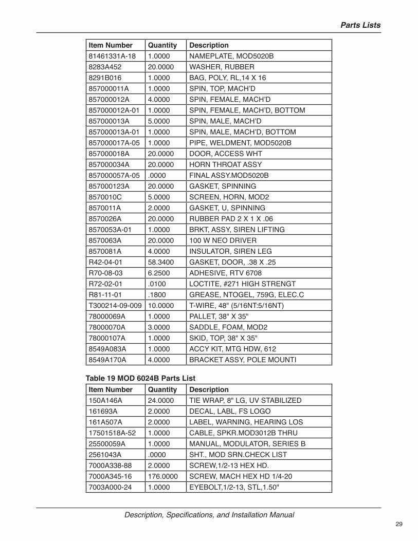
Item Number Quantity Description81461331A-18 1.0000 NAMEPLATE, MOD5020B8283A452 20.0000 WASHER, RUBBER8291B016 1.0000 BAG, POLY, RL,14 X 16857000011A 1.0000 SPIN, TOP, MACH’D857000012A 4.0000 SPIN, FEMALE, MACH’D857000012A-01 1.0000 SPIN, FEMALE, MACH’D, BOTTOM857000013A 5.0000 SPIN, MALE, MACH’D857000013A-01 1.0000 SPIN, MALE, MACH’D, BOTTOM857000017A-05 1.0000 PIPE, WELDMENT, MOD5020B857000018A 20.0000 DOOR, ACCESS WHT857000034A 20.0000 HORN THROAT ASSY857000057A-05 .0000 FINAL ASSY.MOD5020B857000123A 20.0000 GASKET, SPINNING8570010C 5.0000 SCREEN, HORN, MOD28570011A 2.0000 GASKET, U, SPINNING8570026A 20.0000 RUBBER PAD 2 X 1 X .068570053A-01 1.0000 BRKT, ASSY, SIREN LIFTING8570063A 20.0000 100 W NEO DRIVER8570081A 4.0000 INSULATOR, SIREN LEGR42-04-01 58.3400 GASKET, DOOR, .38 X .25R70-08-03 6.2500 ADHESIVE, RTV 6708R72-02-01 .0100 LOCTITE, #271 HIGH STRENGTR81-11-01 .1800 GREASE, NTOGEL, 759G, ELEC.CT300214-09-009 10.0000 T-WIRE, 48" (5/16NT:5/16NT)78000069A 1.0000 PALLET, 38" X 35"78000070A 3.0000 SADDLE, FOAM, MOD278000107A 1.0000 SKID, TOP, 38" X 35"8549A083A 1.0000 ACCY KIT, MTG HDW, 6128549A170A 4.0000 BRACKET ASSY, POLE MOUNTI
Table 19 MOD 6024B Parts ListItem Number Quantity Description150A146A 24.0000 TIE WRAP, 8" LG, UV STABILIZED161693A 2.0000 DECAL, LABL, FS LOGO161A507A 2.0000 LABEL, WARNING, HEARING LOS17501518A-52 1.0000 CABLE, SPKR.MOD3012B THRU25500059A 1.0000 MANUAL, MODULATOR, SERIES B2561043A .0000 SHT., MOD SRN.CHECK LIST7000A338-88 2.0000 SCREW,1/2-13 HEX HD.7000A345-16 176.0000 SCREW, MACH HEX HD 1/4-207003A000-24 1.0000 EYEBOLT,1/2-13, STL,1.50"

30
Parts Lists
Modulator High-Powered Omni Speaker (MOD Series)
Item Number Quantity Description7004A004-32 2.0000 BOLT, CRG RD HD STL 3/8-167004A004-56 6.0000 BOLT, CRG STL 3/8-16 X 3-17057A032 8.0000 NUT, HEX DBL CHAM STL7058A010 48.0000 NUT, EL STOP HEX LT SS7059A077 2.0000 NUT, HEX, STL, CAD,1/2-137065A049A 100.0000 RIVNUT, 1/4-207072A024 224.0000 WASH, FLT, SS, .266 X 11/167072A036 8.0000 WASHER, FLAT 3/8 IN. NOM I7072A038 1.0000 WASH, FLT, RBR, .9/16 X 1-3/47072A095 1.0000 WASH, FLT, STL, 1/2 X 1-3/47072A148A 24.0000 WASH, FLT NEOPRENE 5/8 OD7074A025 2.0000 LKWASH, SPLIT STL 1/2 SCR7074A067 152.0000 LKWASHER, SPLIT, SS7099A103-15 2.0000 RIVET, POP, ALUM,1/8 HD, .26581461331A-19 1.0000 NAMEPLATE, MOD6024B8283A452 24.0000 WASHER, RUBBER8291B016 1.0000 BAG, POLY, RL,14 X 16857000011A 1.0000 SPIN, TOP, MACH’D857000012A 5.0000 SPIN, FEMALE, MACH’D857000012A-01 1.0000 SPIN, FEMALE, MACH’D, BOTTOM857000013A 6.0000 SPIN, MALE, MACH’D857000013A-01 1.0000 SPIN, MALE, MACH’D, BOTTOM857000017A-06 1.0000 PIPE, WELDMENT, MOD6024B857000018A 24.0000 DOOR, ACCESS WHT857000034A 24.0000 HORN THROAT ASSY857000057A-06 .0000 FINAL ASSY.MOD6024B857000123A 24.0000 GASKET, SPINNING8570010C 6.0000 SCREEN, HORN, MOD28570011A 2.0000 GASKET, U, SPINNING8570026A 24.0000 RUBBER PAD 2 X 1 X .068570053A-01 1.0000 BRKT, ASSY, SIREN LIFTING8570081A 4.0000 INSULATOR, SIREN LEGR42-04-01 70.0000 GASKET, DOOR, .38 X .25R70-08-03 7.5000 ADHESIVE, RTV 6708R72-02-01 .0100 LOCTITE, #271 HIGH STRENGTR81-11-01 .2000 GREASE, NTOGEL, 759G, ELEC.CT300214-09-009 12.0000 T-WIRE, 48" (5/16NT:5/16NT)78000069A 1.0000 PALLET, 38" X 35"78000070A 3.0000 SADDLE, FOAM, MOD278000107A 1.0000 SKID, TOP, 38" X 35"8549A083A 1.0000 ACCY KIT, MTG HDW, 612
31
Parts Lists
Description, Specifications, and Installation Manual
Item Number Quantity Description8549A170A 4.0000 BRACKET ASSY, POLE MOUNTI8570063A 24.0000 100 W NEO DRIVER
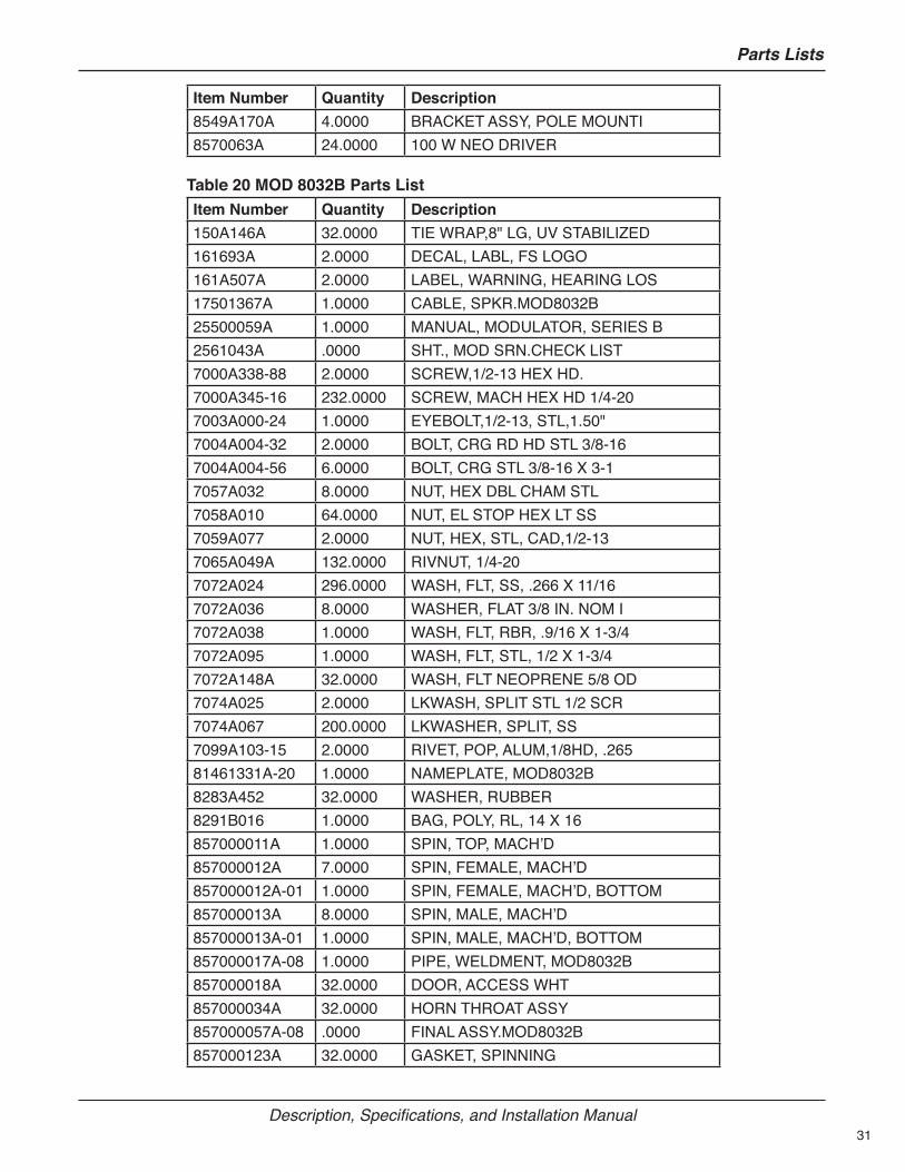
Table 20 MOD 8032B Parts ListItem Number Quantity Description150A146A 32.0000 TIE WRAP,8" LG, UV STABILIZED161693A 2.0000 DECAL, LABL, FS LOGO161A507A 2.0000 LABEL, WARNING, HEARING LOS17501367A 1.0000 CABLE, SPKR.MOD8032B25500059A 1.0000 MANUAL, MODULATOR, SERIES B2561043A .0000 SHT., MOD SRN.CHECK LIST7000A338-88 2.0000 SCREW,1/2-13 HEX HD.7000A345-16 232.0000 SCREW, MACH HEX HD 1/4-207003A000-24 1.0000 EYEBOLT,1/2-13, STL,1.50"7004A004-32 2.0000 BOLT, CRG RD HD STL 3/8-167004A004-56 6.0000 BOLT, CRG STL 3/8-16 X 3-17057A032 8.0000 NUT, HEX DBL CHAM STL7058A010 64.0000 NUT, EL STOP HEX LT SS7059A077 2.0000 NUT, HEX, STL, CAD,1/2-137065A049A 132.0000 RIVNUT, 1/4-207072A024 296.0000 WASH, FLT, SS, .266 X 11/167072A036 8.0000 WASHER, FLAT 3/8 IN. NOM I7072A038 1.0000 WASH, FLT, RBR, .9/16 X 1-3/47072A095 1.0000 WASH, FLT, STL, 1/2 X 1-3/47072A148A 32.0000 WASH, FLT NEOPRENE 5/8 OD7074A025 2.0000 LKWASH, SPLIT STL 1/2 SCR7074A067 200.0000 LKWASHER, SPLIT, SS7099A103-15 2.0000 RIVET, POP, ALUM,1/8HD, .26581461331A-20 1.0000 NAMEPLATE, MOD8032B8283A452 32.0000 WASHER, RUBBER8291B016 1.0000 BAG, POLY, RL, 14 X 16857000011A 1.0000 SPIN, TOP, MACH’D857000012A 7.0000 SPIN, FEMALE, MACH’D857000012A-01 1.0000 SPIN, FEMALE, MACH’D, BOTTOM857000013A 8.0000 SPIN, MALE, MACH’D857000013A-01 1.0000 SPIN, MALE, MACH’D, BOTTOM857000017A-08 1.0000 PIPE, WELDMENT, MOD8032B857000018A 32.0000 DOOR, ACCESS WHT857000034A 32.0000 HORN THROAT ASSY857000057A-08 .0000 FINAL ASSY.MOD8032B857000123A 32.0000 GASKET, SPINNING

32
Getting Service
Modulator High-Powered Omni Speaker (MOD Series)
Item Number Quantity Description8570010C 8.0000 SCREEN, HORN, MOD28570011A 2.0000 GASKET, U, SPINNING8570026A 32.0000 RUBBER PAD 2 X 1 X .068570053A-01 1.0000 BRKT, ASSY, SIREN LIFTING8570081A 4.0000 INSULATOR, SIREN LEGR42-04-01 78.0000 GASKET, DOOR, .38 X .25R70-08-03 10.0000 ADHESIVE, RTV 6708R72-02-01 .0100 LOCTITE, #271 HIGH STRENGTR81-11-01 .2400 GREASE, NTOGEL,759G, ELEC.CT300214-09-009 16.0000 T-WIRE, 48" (5/16NT:5/16NT)78000069A 1.0000 PALLET, 38" X 35"78000070A 4.0000 SADDLE, FOAM, MOD278000107A 1.0000 SKID, TOP, 38" X 35"8549A083A 1.0000 ACCY KIT, MTG HDW, 6128549A170A 4.0000 BRACKET ASSY, POLE MOUNTI8570063A 32.0000 100 W NEO DRIVER
Ordering PartsTo order replacement parts, call Customer Care. See Getting Service.
Table 21 Replacement PartsDescription Part NumberTop Light Kit 191XL-024RSide Light Kit MOD-QF-KIT
Getting ServiceIf you are experiencing any difficulties, contact Federal Signal Customer Care at: 800-548-7229 or 708-534-3400 extension 5822 or Technical Support at: 800-524-3021 or 708-534-3400 extension 7329 or through e-mail at: [email protected]. For instruction manuals and information on related products, visit: http://www.fedsig.com/