Embed Size (px)
Citation preview

MODULE 1
1. INTRODUCTION
WHAT IS A COMPUTER NETWORK?
o Computer Network is a group of computers connected with each other through wires,
optical fibres or optical links so that various devices can interact with each other
through a network.
o The aim of the computer network is the sharing of resources among various devices.
o In the case of computer network technology, there are several types of networks that
vary from simple to complex level.
Following are the advantages
o Security: It provides limited interaction that a user can have with the entire system. For
example, a bank allows the users to access their own accounts through an ATM without
allowing them to access the bank's entire database.
o Faster problem solving: Multiple computers can solve the problem faster than a single
machine working alone.
o Security through redundancy: Multiple computers running the same program at the
same time can provide the security through redundancy. For example, if four computers
run the same program and any computer has a hardware error, then other computers can
override it.
Major components of a computer network are:
NIC(Network interface card)
NIC is a device that helps the computer to communicate with another device. The network
interface card contains the hardware addresses, the data-link layer protocol use this address to
identify the system on the network so that it transfers the data to the correct destination.
There are two types of NIC: wireless NIC and wired NIC.
o Wireless NIC: All the modern laptops use the wireless NIC. In Wireless NIC, a
connection is made using the antenna that employs the radio wave technology.

o Wired NIC: Cables use the wired NIC to transfer the data over the medium.
Hub: Hub is a central device that splits the network connection into multiple devices. When
computer requests for information from a computer, it sends the request to the Hub. Hub
distributes this request to all the interconnected computers.
Switches: Switch is a networking device that groups all the devices over the network to transfer
the data to another device. A switch is better than Hub as it does not broadcast the message
over the network, i.e., it sends the message to the device for which it belongs to. Therefore, we
can say that switch sends the message directly from source to the destination.
Cables and connectors: Cable is a transmission media that transmits the communication
signals. There are three types of cables:
o Twisted pair cable: It is a high-speed cable that transmits the data over 1Gbps or
more.
o Coaxial cable: Coaxial cable resembles like a TV installation cable. Coaxial cable is
more expensive than twisted pair cable, but it provides the high data transmission speed.
o Fibre optic cable: Fibre optic cable is a high-speed cable that transmits the data using
light beams. It provides high data transmission speed as compared to other cables. It is
more expensive as compared to other cables, so it is installed at the government level.
Router: Router is a device that connects the LAN to the internet. The router is mainly used to
connect the distinct networks or connect the internet to multiple computers.
Modem: Modem connects the computer to the internet over the existing telephone line. A
modem is not integrated with the computer motherboard. A modem is a separate part on the
PC slot found on the motherboard.
Uses of Computer Network
o Resource sharing: Resource sharing is the sharing of resources such as programs,
printers, and data among the users on the network without the requirement of the
physical location of the resource and user.
o Server-Client model: Computer networking is used in the server-client model. A
server is a central computer used to store the information and maintained by the system

administrator. Clients are the machines used to access the information stored in the
server remotely.
o Communication medium: Computer network behaves as a communication medium
among the users. For example, a company contains more than one computer has an
email system which the employees use for daily communication.
o E-commerce: Computer network is also important in businesses. We can do the
business over the internet. For example, amazon.com is doing their business over the
internet, i.e., they are doing their business over the internet.
Features Of Computer network
A list Of Computer network features is given below.
o Communication speed
o File sharing
o Back up and Roll back is easy
o Software and Hardware sharing
o Security
o Scalability
o Reliability
Communication speed: Network provides us to communicate over the network in a fast and
efficient manner. For example, we can do video conferencing, email messaging, etc. over the
internet. Therefore, the computer network is a great way to share our knowledge and ideas.
File sharing: File sharing is one of the major advantage of the computer network. Computer
network provides us to share the files with each other.
Back up and Roll back is easy: Since the files are stored in the main server which is centrally
located. Therefore, it is easy to take the back up from the main server.

Software and Hardware sharing: We can install the applications on the main server,
therefore, the user can access the applications centrally. So, we do not need to install the
software on every machine. Similarly, hardware can also be shared.
Security: Network allows the security by ensuring that the user has the right to access the
certain files and applications.
Scalability:Scalability means that we can add the new components on the network. Network
must be scalable so that we can extend the network by adding new devices. But, it decreases
the speed of the connection and data of the transmission speed also decreases, this increases
the chances of error occurring. This problem can be overcome by using the routing or switching
devices.
Reliability: Computer network can use the alternative source for the data communication in
case of any hardware failure.
COMPUTER NETWORK TYPES
A computer network is a group of computers linked to each other that enables the computer to
communicate with another computer and share their resources, data, and applications.A
computer network can be categorized by their size. A computer network is mainly of four
types
o LAN(Local Area Network)
o PAN(Personal Area Network)
o MAN(Metropolitan Area Network)
o WAN(Wide Area Network)
LAN(Local Area Network)
o Local Area Network is a group of computers connected to each other in a small area
such as building, office.
o LAN is used for connecting two or more personal computers through a communication
medium such as twisted pair, coaxial cable, etc.

o It is less costly as it is built with inexpensive hardware such as hubs, network adapters,
and ethernet cables.
o The data is transferred at an extremely faster rate in Local Area Network.
o Local Area Network provides higher security.
PAN(Personal Area Network)
o Personal Area Network is a network arranged within an individual person, typically
within a range of 10 meters.
o Personal Area Network is used for connecting the computer devices of personal use is
known as Personal Area Network.
o Thomas Zimmerman was the first research scientist to bring the idea of the Personal
Area Network.
o Personal Area Network covers an area of 30 feet.
o Personal computer devices that are used to develop the personal area network are the
laptop, mobile phones, media player and play stations.
There are two types of Personal Area Network:
o Wired Personal Area Network
o Wireless Personal Area Network
Wireless Personal Area Network: Wireless Personal Area Network is developed by simply
using wireless technologies such as WiFi, Bluetooth. It is a low range network.
Wired Personal Area Network: Wired Personal Area Network is created by using the USB.
Examples Of Personal Area Network:
o Body Area Network: Body Area Network is a network that moves with a person. For
example, a mobile network moves with a person. Suppose a person establishes a
network connection and then creates a connection with another device to share the
information.
o Offline Network: An offline network can be created inside the home, so it is also
known as a home network. A home network is designed to integrate the devices such
as printers, computer, television but they are not connected to the internet.

o Small Home Office: It is used to connect a variety of devices to the internet and to a
corporate network using a VPN
MAN(Metropolitan Area Network)
o A metropolitan area network is a network that covers a larger geographic area by
interconnecting a different LAN to form a larger network.
o Government agencies use MAN to connect to the citizens and private industries.
o In MAN, various LANs are connected to each other through a telephone exchange line.
o The most widely used protocols in MAN are RS-232, Frame Relay, ATM, ISDN, OC-
3, ADSL, etc.
o It has a higher range than Local Area Network(LAN).
Uses Of Metropolitan Area Network:
o MAN is used in communication between the banks in a city.
o It can be used in an Airline Reservation.
o It can be used in a college within a city.
o It can also be used for communication in the military.
WAN(Wide Area Network)
o A Wide Area Network is a network that extends over a large geographical area such as
states or countries.
o A Wide Area Network is quite bigger network than the LAN.
o A Wide Area Network is not limited to a single location, but it spans over a large
geographical area through a telephone line, fibre optic cable or satellite links.
o The internet is one of the biggest WAN in the world.
o A Wide Area Network is widely used in the field of Business, government, and
education.
Examples Of Wide Area Network:
o Mobile Broadband: A 4G network is widely used across a region or country.

o Last mile: A telecom company is used to provide the internet services to the customers
in hundreds of cities by connecting their home with fiber.
o Private network: A bank provides a private network that connects the 44 offices. This
network is made by using the telephone leased line provided by the telecom company.
Advantages Of Wide Area Network:
o Geographical area: A Wide Area Network provides a large geographical area.
Suppose if the branch of our office is in a different city then we can connect with them
through WAN. The internet provides a leased line through which we can connect with
another branch.
o Centralized data: In case of WAN network, data is centralized. Therefore, we do not
need to buy the emails, files or back up servers.
o Get updated files: Software companies work on the live server. Therefore, the
programmers get the updated files within seconds.
o Exchange messages: In a WAN network, messages are transmitted fast. The web
application like Facebook, Whatsapp, Skype allows you to communicate with friends.
o Sharing of software and resources: In WAN network, we can share the software and
other resources like a hard drive, RAM.
o Global business: We can do the business over the internet globally.
o High bandwidth: If we use the leased lines for our company then this gives the high
bandwidth. The high bandwidth increases the data transfer rate which in turn increases
the productivity of our company.
Disadvantages of Wide Area Network::
o Security issue: A WAN network has more security issues as compared to LAN and
MAN network as all the technologies are combined together that creates the security
problem.
o Needs Firewall & antivirus software: The data is transferred on the internet which
can be changed or hacked by the hackers, so the firewall needs to be used. Some people
can inject the virus in our system so antivirus is needed to protect from such a virus.
o High Setup cost: An installation cost of the WAN network is high as it involves the
purchasing of routers, switches.

o Troubleshooting problems: It covers a large area so fixing the problem is difficult.
2. PROTOCOLS
"Protocols" which are set of rules that help in governing the way a particular technology will
function for communication.
1. Transmission Control Protocol (TCP)
2. Internet Protocol (IP)
3. User Datagram Protocol (UDP)
4. Post office Protocol (POP)
5. Simple mail transport Protocol (SMTP)
6. File Transfer Protocol (FTP)
7. Hyper Text Transfer Protocol (HTTP)
8. Hyper Text Transfer Protocol Secure (HTTPS)
9. Telnet
10. Gopher
1. Transmission Control Protocol (TCP): TCP is a popular communication protocol which is
used for communicating over a network. It divides any message into series of packets that are
sent from source to destination and there it gets reassembled at the destination.
2. Internet Protocol (IP): IP is designed explicitly as addressing protocol. It is mostly used
with TCP. The IP addresses in packets help in routing them through different nodes in a
network until it reaches the destination system. TCP/IP is the most popular protocol
connecting the networks.
3. User Datagram Protocol (UDP): UDP is a substitute communication protocol to
Transmission Control Protocol implemented primarily for creating loss-tolerating and low-
latency linking between different applications.
4. Post office Protocol (POP): POP3 is designed for receiving incoming E-mails.

5. Simple mail transport Protocol (SMTP): SMTP is designed to send and distribute outgoing
E-Mail.
6. File Transfer Protocol (FTP): FTP allows users to transfer files from one machine to
another. Types of files may include program files, multimedia files, text files, and documents,
etc.
7. Hyper Text Transfer Protocol (HTTP): HTTP is designed for transferring a hypertext
among two or more systems. HTML tags are used for creating links. These links may be in
any form like text or images. HTTP is designed on Client-server principles which allow a
client system for establishing a connection with the server machine for making a request. The
server acknowledges the request initiated by the client and responds accordingly.
8. Hyper Text Transfer Protocol Secure (HTTPS): HTTPS is abbreviated as Hyper Text
Transfer Protocol Secure is a standard protocol to secure the communication among two
computers one using the browser and other fetching data from web server. HTTP is used for
transferring data between the client browser (request) and the web server (response) in the
hypertext format, same in case of HTTPS except that the transferring of data is done in an
encrypted format. So it can be said that https thwart hackers from interpretation or
modification of data throughout the transfer of packets.
9. Telnet: Telnet is a set of rules designed for connecting one system with another. The
connecting process here is termed as remote login. The system which requests for connection
is the local computer, and the system which accepts the connection is the remote computer.
10. Gopher: Gopher is a collection of rules implemented for searching, retrieving as well as
displaying documents from isolated sites. Gopher also works on the client/server principle.
PROTOCOL LAYERING
Protocol layering is a common technique to simplify networking designs by dividing them into
functional layers, and assigning protocols to perform each layer's task.
For example, it is common to separate the functions of data delivery and connection
management into separate layers, and therefore separate protocols. Thus, one protocol is
designed to perform data delivery, and another protocol, layered above the first, performs
connection management. The data delivery protocol is fairly simple and knows nothing of

connection management. The connection management protocol is also fairly simple, since it
doesn't need to concern itself with data delivery.
Protocol layering produces simple protocols, each with a few well-defined tasks. These
protocols can then be assembled into a useful whole. Individual protocols can also be removed
or replaced as needed for particular applications.
The most important layered protocol designs are the Internet's original DoD model, and the
OSI Seven Layer Model. The modern Internet represents a fusion of both models.
• DoD Four-Layer Model
• OSI Seven layer model
DoD Four-Layer Model
The Department of Defense Four-Layer Model was developed in the 1970s for the DARPA
Internetwork Project that eventually grew into the Internet. The core Internet protocols adhere
to this model, although the OSI Seven Layer Model is justly preferred for new designs.
The four layers in the DoD model, from bottom to top, are:
1. The Network Access Layer is responsible for delivering data over the particular
hardware media in use. Different protocols are selected from this layer, depending on
the type of physical network.
2. The Internet Layer is responsible for delivering data across a series of different
physical networks that interconnect a source and destination machine. Routing
protocols are most closely associated with this layer, as is the IP Protocol, the Internet's
fundamental protocol.

3. The Host-to-Host Layer handles connection rendezvous, flow control, retransmission
of lost data, and other generic data flow management. The mutually exclusive TCP and
UDP protocols are this layer's most important members.
4. The Process Layer contains protocols that implement user-level functions, such as
mail delivery, file transfer and remote login
3. OSI Model
OSI stands for Open Systems Interconnection. It has been developed by ISO –
‘International Organization of Standardization‘, in the year 1984. It is a 7 layer
architecture with each layer having specific functionality to perform. All these 7 layers work
collaboratively to transmit the data from one person to another across the globe.
1. Physical Layer (Layer 1) :
The lowest layer of the OSI reference model is the physical layer. It is responsible for the
actual physical connection between the devices. The physical layer contains information in
the form of bits. It is responsible for transmitting individual bits from one node to the next.
When receiving data, this layer will get the signal received and convert it into 0s and 1s and
send them to the Data Link layer, which will put the frame back together.

The functions of the physical layer are :
1. Bit synchronization: The physical layer provides the synchronization of the bits by
providing a clock. This clock controls both sender and receiver thus providing
synchronization at bit level.
2. Bit rate control: The Physical layer also defines the transmission rate i.e. the number of
bits sent per second.
3. Physical topologies: Physical layer specifies the way in which the different,
devices/nodes are arranged in a network i.e. bus, star or mesh topolgy.
4. Transmission mode: Physical layer also defines the way in which the data flows between
the two connected devices. The various transmission modes possible are: Simplex, half-
duplex and full-duplex.
* Hub, Repeater, Modem, Cables are Physical Layer devices.
** Network Layer, Data Link Layer and Physical Layer are also known as Lower
Layers or Hardware Layers.
2. Data Link Layer (DLL) (Layer 2) :
The data link layer is responsible for the node to node delivery of the message. The main
function of this layer is to make sure data transfer is error-free from one node to another, over
the physical layer. When a packet arrives in a network, it is the responsibility of DLL to
transmit it to the Host using its MAC address.
Data Link Layer is divided into two sub layers :
1. Logical Link Control (LLC)
2. Media Access Control (MAC)

The functions of the data Link layer are :
1. Framing: Framing is a function of the data link layer. It provides a way for a sender to
transmit a set of bits that are meaningful to the receiver. This can be accomplished by
attaching special bit patterns to the beginning and end of the frame.
2. Physical addressing: After creating frames, Data link layer adds physical addresses
(MAC address) of sender and/or receiver in the header of each frame.
3. Error control: Data link layer provides the mechanism of error control in which it
detects and retransmits damaged or lost frames.
4. Flow Control: The data rate must be constant on both sides else the data may get
corrupted thus , flow control coordinates that amount of data that can be sent before
receiving acknowledgement.
5. Access control: When a single communication channel is shared by multiple devices,
MAC sub-layer of data link layer helps to determine which device has control over the
channel at a given time.
* Packet in Data Link layer is referred as Frame.
** Data Link layer is handled by the NIC (Network Interface Card) and device drivers of
host machines.
*** Switch & Bridge are Data Link Layer devices.
3. Network Layer (Layer 3) :
Network layer works for the transmission of data from one host to the other located in
different networks. It also takes care of packet routing i.e. selection of the shortest path
to transmit the packet, from the number of routes available. The sender & receiver’s IP
address are placed in the header by the network layer.
The functions of the Network layer are :

1. Routing: The network layer protocols determine which route is suitable from source to
destination. This function of network layer is known as routing.
2. Logical Addressing: In order to identify each device on internetwork uniquely, network
layer defines an addressing scheme. The sender & receiver’s IP address are placed in the
header by network layer. Such an address distinguishes each device uniquely and
universally.
* Segment in Network layer is referred as Packet.
** Network layer is implemented by networking devices such as routers.
4. Transport Layer (Layer 4) :
Transport layer provides services to application layer and takes services from network layer.
The data in the transport layer is referred to as Segments. It is responsible for the End to End
Delivery of the complete message. The transport layer also provides the acknowledgement
of the successful data transmission and re-transmits the data if an error is found.
• At sender’s side:Transport layer receives the formatted data from the upper layers,
performs Segmentation and also implements Flow & Error control to ensure proper data
transmission. It also adds Source and Destination port number in its header and forwards the
segmented data to the Network Layer.
Note: The sender need to know the port number associated with the receiver’s application.
Generally, this destination port number is configured, either by default or manually. For
example, when a web application makes a request to a web server, it typically uses port
number 80, because this is the default port assigned to web applications. Many applications
have default port assigned
• At receiver’s side:Transport Layer reads the port number from its header and forwards the
Data which it has received to the respective application. It also performs sequencing and
reassembling of the segmented data.
The functions of the transport layer are :
1. Segmentation and Reassembly: This layer accepts the message from the (session) layer
, breaks the message into smaller units . Each of the segment produced has a header
associated with it. The transport layer at the destination station reassembles the message.
2. Service Point Addressing: In order to deliver the message to correct process, transport
layer header includes a type of address called service point address or port address. Thus
by specifying this address, transport layer makes sure that the message is delivered to the
correct process.
The services provided by the transport layer :
1. Connection Oriented Service:
2. It is a three-phase process which include
–Connection Establishment
–Data Transfer
–Termination / disconnection
In this type of transmission, the receiving device sends an acknowledgement, back to
the source after a packet or group of packet is received. This type of transmission is
reliable and secure.
3. Connection less service: It is a one-phase process and includes Data Transfer. In this
type of transmission, the receiver does not acknowledge receipt of a packet. This
approach allows for much faster communication between devices. Connection-oriented
service is more reliable than connectionless Service.
* Data in the Transport Layer is called as Segments.
** Transport layer is operated by the Operating System. It is a part of the OS and
communicates with the Application Layer by making system calls.
Transport Layer is called as Heart of OSI model.
5. Session Layer (Layer 5) :
This layer is responsible for establishment of connection, maintenance of sessions,
authentication and also ensures security.
The functions of the session layer are :

1. Session establishment, maintenance and termination: The layer allows the two
processes to establish, use and terminate a connection.
2. Synchronization : This layer allows a process to add checkpoints which are considered
as synchronization points into the data. These synchronization point help to identify the
error so that the data is re-synchronized properly, and ends of the messages are not cut
prematurely and data loss is avoided.
3. Dialog Controller : The session layer allows two systems to start communication with
each other in half-duplex or full-duplex.
**All the below 3 layers(including Session Layer) are integrated as a single layer in the
TCP/IP model as “Application Layer”.
**Implementation of these 3 layers is done by the network application itself. These are also
known as Upper Layers or Software Layers.
SCENARIO:
Let’s consider a scenario where a user wants to send a message through some Messenger
application running in his browser. The “Messenger” here acts as the application layer which
provides the user with an interface to create the data. This message or so-called Data is
compressed, encrypted (if any secure data) and converted into bits (0’s and 1’s) so that it can
be transmitted.
6. Presentation Layer (Layer 6) :
Presentation layer is also called the Translation layer.The data from the application layer is
extracted here and manipulated as per the required format to transmit over the network.
The functions of the presentation layer are :
1. Translation : For example, ASCII to EBCDIC.
2. Encryption/ Decryption : Data encryption translates the data into another form or code.
The encrypted data is known as the cipher text and the decrypted data is known as plain
text. A key value is used for encrypting as well as decrypting data.
3. Compression: Reduces the number of bits that need to be transmitted on the network.
7. Application Layer (Layer 7) :
At the very top of the OSI Reference Model stack of layers, we find Application layer which
is implemented by the network applications. These applications produce the data, which has
to be transferred over the network. This layer also serves as a window for the application
services to access the network and for displaying the received information to the user.
Ex: Application – Browsers, Skype Messenger etc.
**Application Layer is also called as Desktop Layer.
The functions of the Application layer are :
1. Network Virtual Terminal
2. FTAM-File transfer access and management
3. Mail Services
4. Directory Services
OSI model acts as a reference model and is not implemented in the Internet because of its
late invention. Current model being used is the TCP/IP model.
4. TCP/IP Model
o The TCP/IP model was developed prior to the OSI model.
o The TCP/IP model is not exactly similar to the OSI model.
o The TCP/IP model consists of five layers: the application layer, transport layer, network
layer, data link layer and physical layer.
o The first four layers provide physical standards, network interface, internetworking,
and transport functions that correspond to the first four layers of the OSI model and
these four layers are represented in TCP/IP model by a single layer called the
application layer.
o TCP/IP is a hierarchical protocol made up of interactive modules, and each of them
provides specific functionality.
Here, hierarchical means that each upper-layer protocol is supported by two or more lower-
level protocols.
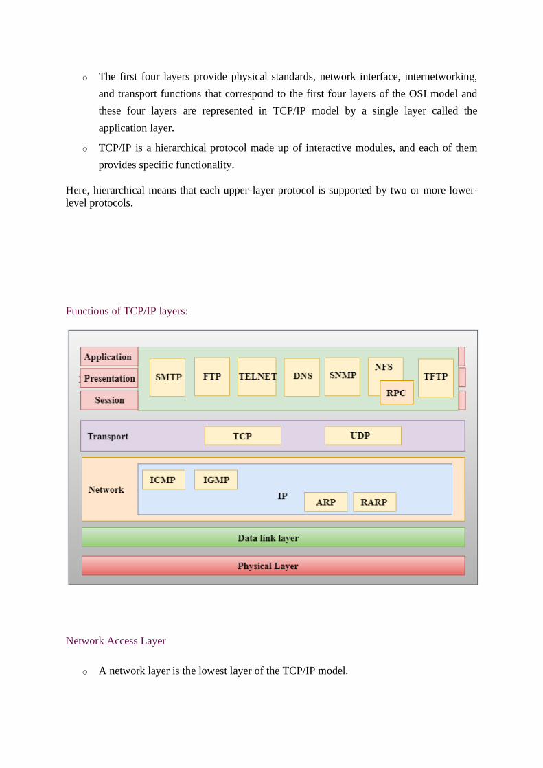
Functions of TCP/IP layers:
Network Access Layer
o A network layer is the lowest layer of the TCP/IP model.

o A network layer is the combination of the Physical layer and Data Link layer defined
in the OSI reference model.
o It defines how the data should be sent physically through the network.
o This layer is mainly responsible for the transmission of the data between two devices
on the same network.
o The functions carried out by this layer are encapsulating the IP datagram into frames
transmitted by the network and mapping of IP addresses into physical addresses.
o The protocols used by this layer are ethernet, token ring, FDDI, X.25, frame relay.
Internet Layer
o An internet layer is the second layer of the TCP/IP model.
o An internet layer is also known as the network layer.
o The main responsibility of the internet layer is to send the packets from any network,
and they arrive at the destination irrespective of the route they take.
Following are the protocols used in this layer are:
IP Protocol: IP protocol is used in this layer, and it is the most significant part of the entire
TCP/IP suite.
Following are the responsibilities of this protocol:
o IP Addressing: This protocol implements logical host addresses known as IP
addresses. The IP addresses are used by the internet and higher layers to identify the
device and to provide internetwork routing.
o Host-to-host communication: It determines the path through which the data is to be
transmitted.
o Data Encapsulation and Formatting: An IP protocol accepts the data from the
transport layer protocol. An IP protocol ensures that the data is sent and received
securely, it encapsulates the data into message known as IP datagram.
o Fragmentation and Reassembly: The limit imposed on the size of the IP datagram by
data link layer protocol is known as Maximum Transmission unit (MTU). If the size of
IP datagram is greater than the MTU unit, then the IP protocol splits the datagram into
smaller units so that they can travel over the local network. Fragmentation can be done
by the sender or intermediate router. At the receiver side, all the fragments are
reassembled to form an original message.

o Routing: When IP datagram is sent over the same local network such as LAN, MAN,
WAN, it is known as direct delivery. When source and destination are on the distant
network, then the IP datagram is sent indirectly. This can be accomplished by routing
the IP datagram through various devices such as routers.
ARP Protocol
o ARP stands for Address Resolution Protocol.
o ARP is a network layer protocol which is used to find the physical address from the IP
address.
o The two terms are mainly associated with the ARP Protocol:
o ARP request: When a sender wants to know the physical address of the device,
it broadcasts the ARP request to the network.
o ARP reply: Every device attached to the network will accept the ARP request
and process the request, but only recipient recognize the IP address and sends
back its physical address in the form of ARP reply. The recipient adds the
physical address both to its cache memory and to the datagram header
ICMP Protocol
o ICMP stands for Internet Control Message Protocol.
o It is a mechanism used by the hosts or routers to send notifications regarding datagram
problems back to the sender.
o A datagram travels from router-to-router until it reaches its destination. If a router is
unable to route the data because of some unusual conditions such as disabled links, a
device is on fire or network congestion, then the ICMP protocol is used to inform the
sender that the datagram is undeliverable.
o An ICMP protocol mainly uses two terms:
o ICMP Test: ICMP Test is used to test whether the destination is reachable or
not.
o ICMP Reply: ICMP Reply is used to check whether the destination device is
responding or not.
o The core responsibility of the ICMP protocol is to report the problems, not correct them.
The responsibility of the correction lies with the sender.
o ICMP can send the messages only to the source, but not to the intermediate routers
because the IP datagram carries the addresses of the source and destination but not of
the router that it is passed to.

Transport Layer
The transport layer is responsible for the reliability, flow control, and correction of data which
is being sent over the network.
The two protocols used in the transport layer are User Datagram protocol and Transmission
control protocol.
o User Datagram Protocol (UDP)
o It provides connectionless service and end-to-end delivery of transmission.
o It is an unreliable protocol as it discovers the errors but not specify the error.
o User Datagram Protocol discovers the error, and ICMP protocol reports the
error to the sender that user datagram has been damaged.
o UDP consists of the following fields:
Source port address: The source port address is the address of the application
program that has created the message.
Destination port address: The destination port address is the address of the
application program that receives the message.
Total length: It defines the total number of bytes of the user datagram in bytes.
Checksum: The checksum is a 16-bit field used in error detection.
o UDP does not specify which packet is lost. UDP contains only checksum; it
does not contain any ID of a data segment.
o Transmission Control Protocol (TCP)
o It provides a full transport layer services to applications.
o It creates a virtual circuit between the sender and receiver, and it is active for
the duration of the transmission.

o TCP is a reliable protocol as it detects the error and retransmits the damaged
frames. Therefore, it ensures all the segments must be received and
acknowledged before the transmission is considered to be completed and a
virtual circuit is discarded.
o At the sending end, TCP divides the whole message into smaller units known
as segment, and each segment contains a sequence number which is required
for reordering the frames to form an original message.
o At the receiving end, TCP collects all the segments and reorders them based on
sequence numbers.
Application Layer
o An application layer is the topmost layer in the TCP/IP model.
o It is responsible for handling high-level protocols, issues of representation.
o This layer allows the user to interact with the application.
o When one application layer protocol wants to communicate with another application
layer, it forwards its data to the transport layer.
o There is an ambiguity occurs in the application layer. Every application cannot be
placed inside the application layer except those who interact with the communication
system. For example: text editor cannot be considered in application layer while web
browser using HTTP protocol to interact with the network where HTTP protocol is an
application layer protocol.
Following are the main protocols used in the application layer:
o HTTP: HTTP stands for Hypertext transfer protocol. This protocol allows us to access
the data over the world wide web. It transfers the data in the form of plain text, audio,
video. It is known as a Hypertext transfer protocol as it has the efficiency to use in a
hypertext environment where there are rapid jumps from one document to another.
o SNMP: SNMP stands for Simple Network Management Protocol. It is a framework
used for managing the devices on the internet by using the TCP/IP protocol suite.
o SMTP: SMTP stands for Simple mail transfer protocol. The TCP/IP protocol that
supports the e-mail is known as a Simple mail transfer protocol. This protocol is used
to send the data to another e-mail address.

o DNS: DNS stands for Domain Name System. An IP address is used to identify the
connection of a host to the internet uniquely. But, people prefer to use the names instead
of addresses. Therefore, the system that maps the name to the address is known as
Domain Name System.
o TELNET: It is an abbreviation for Terminal Network. It establishes the connection
between the local computer and remote computer in such a way that the local terminal
appears to be a terminal at the remote system.
o FTP: FTP stands for File Transfer Protocol. FTP is a standard internet protocol used
for transmitting the files from one computer to another computer.
5. SWITCHING TECHNIQUES
In large networks, there can be multiple paths from sender to receiver. The switching
technique will decide the best route for data transmission.
Switching technique is used to connect the systems for making one-to-one communication.
Classification Of Switching Techniques

Circuit Switching
o Circuit switching is a switching technique that establishes a dedicated path between
sender and receiver.
o In the Circuit Switching Technique, once the connection is established then the
dedicated path will remain to exist until the connection is terminated.
o Circuit switching in a network operates in a similar way as the telephone works.
o A complete end-to-end path must exist before the communication takes place.
o In case of circuit switching technique, when any user wants to send the data, voice,
video, a request signal is sent to the receiver then the receiver sends back the
acknowledgment to ensure the availability of the dedicated path. After receiving the
acknowledgment, dedicated path transfers the data.
o Circuit switching is used in public telephone network. It is used for voice
transmission.
o Fixed data can be transferred at a time in circuit switching technology.
Communication through circuit switching has 3 phases:
o Circuit establishment
o Data transfer
o Circuit Disconnect

Circuit Switching can use either of the two technologies:
Space Division Switches:
o Space Division Switching is a circuit switching technology in which a single
transmission path is accomplished in a switch by using a physically separate set of
crosspoints.
o Space Division Switching can be achieved by using crossbar switch. A crossbar
switch is a metallic crosspoint or semiconductor gate that can be enabled or disabled
by a control unit.
o The Crossbar switch is made by using the semiconductor. For example, Xilinx
crossbar switch using FPGAs.
o Space Division Switching has high speed, high capacity, and nonblocking switches.
Space Division Switches can be categorized in two ways:
o Crossbar Switch
o Multistage Switch
Crossbar Switch
The Crossbar switch is a switch that has n input lines and n output lines. The crossbar switch
has n2 intersection points known as crosspoints.
Disadvantage of Crossbar switch:
The number of crosspoints increases as the number of stations is increased. Therefore, it
becomes very expensive for a large switch. The solution to this is to use a multistage switch.
Multistage Switch
o Multistage Switch is made by splitting the crossbar switch into the smaller units and
then interconnecting them.

o It reduces the number of crosspoints.
o If one path fails, then there will be an availability of another path.
Advantages Of Circuit Switching:
o In the case of Circuit Switching technique, the communication channel is dedicated.
o It has fixed bandwidth.
Disadvantages Of Circuit Switching:
o Once the dedicated path is established, the only delay occurs in the speed of data
transmission.
o It takes a long time to establish a connection approx 10 seconds during which no data
can be transmitted.
o It is more expensive than other switching techniques as a dedicated path is required
for each connection.
o It is inefficient to use because once the path is established and no data is transferred,
then the capacity of the path is wasted.
o In this case, the connection is dedicated therefore no other data can be transferred
even if the channel is free.
Message Switching
o Message Switching is a switching technique in which a message is transferred as a
complete unit and routed through intermediate nodes at which it is stored and
forwarded.
o In Message Switching technique, there is no establishment of a dedicated path
between the sender and receiver.
o The destination address is appended to the message. Message Switching provides a
dynamic routing as the message is routed through the intermediate nodes based on the
information available in the message.
o Message switches are programmed in such a way so that they can provide the most
efficient routes.
o Each and every node stores the entire message and then forward it to the next node.
This type of network is known as store and forward network.
o Message switching treats each message as an independent entity.

Advantages Of Message Switching
o Data channels are shared among the communicating devices that improve the
efficiency of using available bandwidth.
o Traffic congestion can be reduced because the message is temporarily stored in the
nodes.
o Message priority can be used to manage the network.
o The size of the message which is sent over the network can be varied. Therefore, it
supports the data of unlimited size.
Disadvantages Of Message Switching
o The message switches must be equipped with sufficient storage to enable them to
store the messages until the message is forwarded.
o The Long delay can occur due to the storing and forwarding facility provided by the
message switching technique.
Packet Switching
o The packet switching is a switching technique in which the message is sent in one go,
but it is divided into smaller pieces, and they are sent individually.
o The message splits into smaller pieces known as packets and packets are given a
unique number to identify their order at the receiving end.
o Every packet contains some information in its headers such as source address,
destination address and sequence number.
o Packets will travel across the network, taking the shortest path as possible.
o All the packets are reassembled at the receiving end in correct order.
o If any packet is missing or corrupted, then the message will be sent to resend the
message.

o If the correct order of the packets is reached, then the acknowledgment message will
be sent.
Approaches Of Packet Switching:
There are two approaches to Packet Switching:
Datagram Packet switching:
o It is a packet switching technology in which packet is known as a datagram, is
considered as an independent entity. Each packet contains the information about the
destination and switch uses this information to forward the packet to the correct
destination.
o The packets are reassembled at the receiving end in correct order.
o In Datagram Packet Switching technique, the path is not fixed.
o Intermediate nodes take the routing decisions to forward the packets.
o Datagram Packet Switching is also known as connectionless switching.
Virtual Circuit Switching
o Virtual Circuit Switching is also known as connection-oriented switching.
o In the case of Virtual circuit switching, a preplanned route is established before the
messages are sent.
o Call request and call accept packets are used to establish the connection between
sender and receiver.
o In this case, the path is fixed for the duration of a logical connection.

Let's understand the concept of virtual circuit switching through a diagram:
o In the above diagram, A and B are the sender and receiver respectively. 1 and 2 are
the nodes.
o Call request and call accept packets are used to establish a connection between the
sender and receiver.
o When a route is established, data will be transferred.
o After transmission of data, an acknowledgment signal is sent by the receiver that the
message has been received.
o If the user wants to terminate the connection, a clear signal is sent for the termination.
Differences b/w Datagram approach and Virtual Circuit approach
Advantages Of Packet Switching:
o Cost-effective: In packet switching technique, switching devices do not require
massive secondary storage to store the packets, so cost is minimized to some extent.
Datagram approach Virtual Circuit approach
Node takes routing decisions to forward the
packets.
Node does not take any routing decision.
Congestion cannot occur as all the packets travel
in different directions.
Congestion can occur when the node is busy, and it does not
allow other packets to pass through.
It is more flexible as all the packets are treated as
an independent entity.
It is not very flexible.

Therefore, we can say that the packet switching technique is a cost-effective
technique.
o Reliable: If any node is busy, then the packets can be rerouted. This ensures that the
Packet Switching technique provides reliable communication.
o Efficient: Packet Switching is an efficient technique. It does not require any
established path prior to the transmission, and many users can use the same
communication channel simultaneously, hence makes use of available bandwidth very
efficiently.
Disadvantages Of Packet Switch
o Packet Switching technique cannot be implemented in those applications that
require low delay and high-quality services.
o The protocols used in a packet switching technique are very complex and
requires high implementation cost.
o If the network is overloaded or corrupted, then it requires retransmission of
lost packets. It can also lead to the loss of critical information if errors are nor
recovered.
6. DELAYS IN COMPUTER NETWORK
The delays, here, means the time for which the processing of a particular packet takes place.
We have the following types of delays in computer network:
1.TransmissionDelay:
The time taken to transmit a packet from the host to the transmission medium is called
Transmission delay.
For example, if bandwidth is 1 bps (every second 1 bit can be transmitted on to the transmission
medium) and data size is 20 bits then what is the transmission delay ? If in one second, 1 bit
can be transmitted. To transmit 20 bits, 20 seconds would be required.
Let B bps is the bandwidth and L bit is the size of the data then transmission delay is,

Tt = L/B
This delay depends upon the following factors:
• If there are multiple active sessions, delay will become significant.
• Increasing bandwidth decreases transmission delay.
• MAC protocol largely influence the delay if link is shared among multiple devices.
• Sending and receiving a packet involves context switch in the operating system, which
takes finite time.
2.Propagation delay:
After the packet is transmitted to the transmission medium, it has to go through the medium
to reach the destination. Hence the time taken by the last bit of the packet to reach the
destination is called propagation delay.
Factors affecting propagation delay:
1. Distance – It takes more time to reach the destination if the distance of the medium is
longer.
2. Velocity – If the velocity(speed) of the signal is higher, the packet will be received faster.
Tp = Distance / Velocity
Note:
Velocity =3 X 10⁸ m/s (for air)
Velocity= 2.1 X 10⁸ m/s (for optical fibre)
3. Queueing delay:
Let the packet is received by the destination, the packet will not be processed by the destination
immediately. It has to wait in queue in something called as buffer. So the amount of time it
waits in queue before being processed is called queueing delay.
In general we can’t calculate queueing delay because we don’t have any formula for that.
This delay depends upon the following factors:
• If size of queue is large, the queuing delay will be huge. If queue is empty there will be less
or no delay.
• If more number of packets are arriving in a short or no time interval, queuing delay will be
large.
• Less the number of servers/links, greater is the queuing delay.
4. Processing delay:
Now the packet will be taken for processing which is called processing delay.
Time taken to process the data packet by processor that is time required by intermediate routers
to decide where to forward the packet, update TTL, perform header checksum calculations.
It also doesn’t have any formula since it depends upon the speed of the processor and speed
of the processor varies from computer to computer.
Note: Both queueing delay and processing delay doesn’t have any formula because they
depend on the speed of the processor
This delay depends upon the following factors:
• It depends on the speed of processor.
Ttotal = Tt + Tp + Tq + Tpro
Ttotal = Tt+Tp
(when taking Tq and Tpro equals to 0)
7. QUALITY-OF-SERVICE (QOS)
refers to traffic control mechanisms that seek to either differentiate performance based on
application or network-operator requirements or provide predictable or guaranteed
performance to applications, sessions or traffic aggregates. Basic phenomenon for QoS means
in terms of packet delay and losses of various kinds.
Need for QoS –
• Video and audio conferencing require bounded delay and loss rate.
• Video and audio streaming requires bounded packet loss rate, it may not be so sensitive to
delay.

• Time-critical applications (real-time control) in which bounded delay is considered to be
an important factor.
• Valuable applications should be provided better services than less valuable applications.
QoS Specification –
QoS requirements can be specified as:
1. Delay
2. Delay Variation(Jitter)
3. Throughput
4. Error Rate
There are two types of QoS Solutions:
1. Stateless Solutions –
Routers maintain no fine grained state about traffic, one positive factor of it is that it is
scalable and robust. But it has weak services as there is no guarantee about kind of delay
or performance in a particular application which we have to encounter.
2. Stateful Solutions –
Routers maintain per flow state as flow is very important in providing the Quality-of-Service
i.e. providing powerful services such as guaranteed services and high resource utilization,
provides protection and is much less scalable and robust.
Integrated Services(IntServ) –
1. An architecture for providing QoS guarantees in IP networks for individual application
sessions.
2. Relies on resource reservation, and routers need to maintain state information of allocated
resources and respond to new call setup requests.
3. Network decides whether to admit or deny a new call setup request.
IntServ QoS Components –
• Resource reservation: call setup signaling, traffic, QoS declaration, per-element admission
control.
• QoS-sensitive scheduling e.g WFQ queue discipline.
• QoS-sensitive routing algorithm(QSPF)

• QoS-sensitive packet discard strategy.
RSVP-Internet Signaling –
It creates and maintains distributed reservation state, initiated by the receiver and scales for
multicast, needs to be refreshed otherwise reservation times out as it is in soft state. Latest paths
discovered through “PATH” messages (forward direction) and used by RESV messages
(reserve direction).
Call Admission –
• Session must first declare it’s QoS requirement and characterize the traffic it will send
through the network.
• R-specification: defines the QoS being requested, i.e. what kind of bound we want on the
delay, what kind of packet loss is acceptable, etc.
• T-specification: defines the traffic characteristics like bustiness in the traffic.
• A signaling protocol is needed to carry the R-spec and T-spec to the routers where
reservation is required.
• Routers will admit calls based on their R-spec, T-spec and based on the current resource
allocated at the routers to other calls.
Diff-Serv –
Differentiated Service is a stateful solution in which each flow doesn’t means a different state.
It provides reduced state services i.e. maintain state only for larger granular flows rather than
end-to-end flows tries to achieve best of both worlds.
Intended to address the following difficulties with IntServ and RSVP:
1. Flexible Service Models:
IntServ has only two classes, want to provide more qualitative service classes: want to
provide ‘relative’ service distinction.
2. Simpler signaling:
Many applications and users may only want to specify a more qualitative notion of service.


![COMPUTER NETWORK UNIT-I - rgpvonline.com · COMPUTER NETWORK UNIT-I Lecture-1 Computer Network: Definitions [RGPV June 2013] A computer network or data network is a …](https://img.pdfslide.net/doc/110x75/5b0418927f8b9a0a548d0f9a/computer-network-unit-i-network-unit-i-lecture-1-computer-network-definitions.jpg)