Embed Size (px)
Citation preview
4/30/2015
1
Module 10: Flow-Measuring Devices
AWWAHydraulics
When you complete this lesson, you should be able to:
Calculate flow rate in open‐channel and full‐flowing pipes.
Introduction
Flow rates in water supply operations are measured by various metering devices, such as weirs or Parshall flumes for open‐channel flow, and venturi meters and orifice meters for closed conduit flow. Graphs and tables are used to help determine flow rates through these devices. By determining flow rate, you can determine the volumetric flow rate entering or leaving a plant, as well as calibrate instrumentation.
Introduction

4/30/2015
2
Weirs may be used to calculate open‐channel flow rates. The two most commonly used weirs are the V‐notch weir and the rectangular weir.
Weirs
V‐notch Weirs
The discharge equation for v‐notch weir overflow is generally expressed as
Weirs
To read a flow rate graph or table pertaining to a weir, you must know two measurements: 1) the height H of the water above the weir crest, and 2) the angle of the weir (for a v‐notch weir) or the length of the crest (for a rectangular weir).
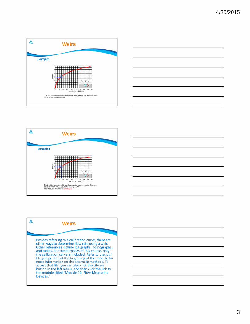
Example1 This example uses a graph of a calibration curve to
solve this problem: Given the discharge curve (calibration curve) for a 60° v‐notch weir, shown below, what is the flow rate in gallons per day when the height of the water above the weir crest is 3 in?
Since the height, or head above the weir crest, is 3 in, begin at the 3 on the Head scale and draw a line until it intersects the calibration curve.
Weirs
4/30/2015
3
Example1
Weirs
Example1
Weirs
Besides referring to a calibration curve, there are other ways to determine flow rate using a weir. Other references include log graphs, nomographs, and tables. For the purposes of this course, only the calibration curve is included. Refer to the .pdffile you printed at the beginning of this module for more information on the alternate methods. To access that file, you can also click the Library button in the left menu, and then click the link to the module titled "Module 10: Flow‐Measuring Devices."
Weirs
4/30/2015
4
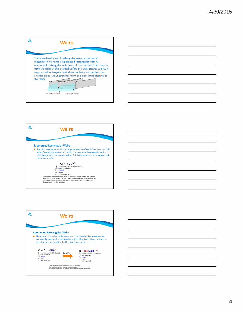
There are two types of rectangular weirs: a contracted rectangular weir and a suppressed rectangular weir. A contracted rectangular weir has end contractions that come in from the sides of the channel before the crest cutout begins. A suppressed rectangular weir does not have end contractions, and the crest cutout stretches from one side of the channel to the other.
Weirs
Suppressed Rectangular Weirs The discharge equation for rectangular weir overflow differs from v‐notch
weirs. Suppressed rectangular weirs and contracted rectangular weirs both take length into consideration. This is the equation for a suppressed rectangular weir.
Weirs
Contracted Rectangular Weirs Because a contracted rectangular weir is somewhat like a suppressed
rectangular weir with a rectangular notch cut out of it, its equation is a variation on the equation for the suppressed weir.
Modify
Weirs
4/30/2015
5
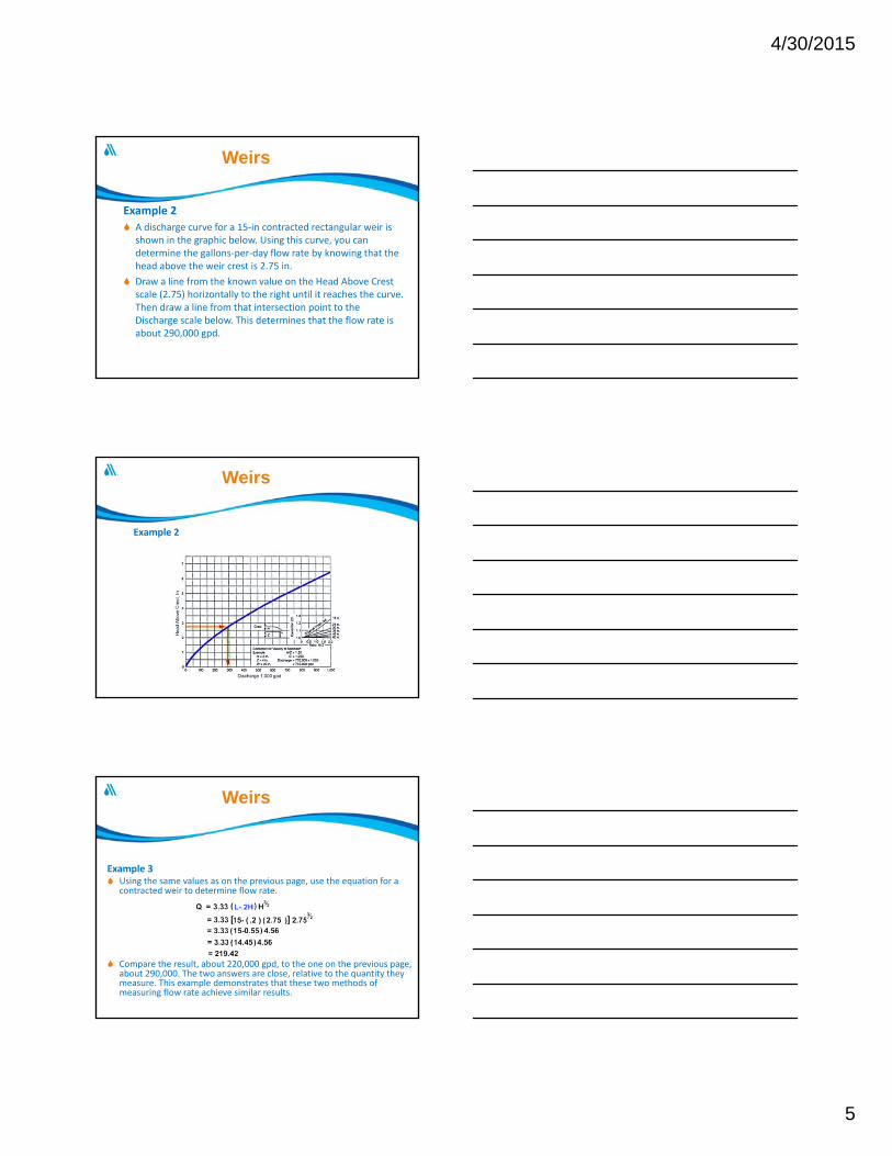
Example 2
A discharge curve for a 15‐in contracted rectangular weir is shown in the graphic below. Using this curve, you can determine the gallons‐per‐day flow rate by knowing that the head above the weir crest is 2.75 in.
Draw a line from the known value on the Head Above Crest scale (2.75) horizontally to the right until it reaches the curve. Then draw a line from that intersection point to the Discharge scale below. This determines that the flow rate is about 290,000 gpd.
Weirs
Example 2
Weirs
Example 3 Using the same values as on the previous page, use the equation for a
contracted weir to determine flow rate.
Compare the result, about 220,000 gpd, to the one on the previous page, about 290,000. The two answers are close, relative to the quantity they measure. This example demonstrates that these two methods of measuring flow rate achieve similar results.
Weirs
4/30/2015
6
Parshall Flumes
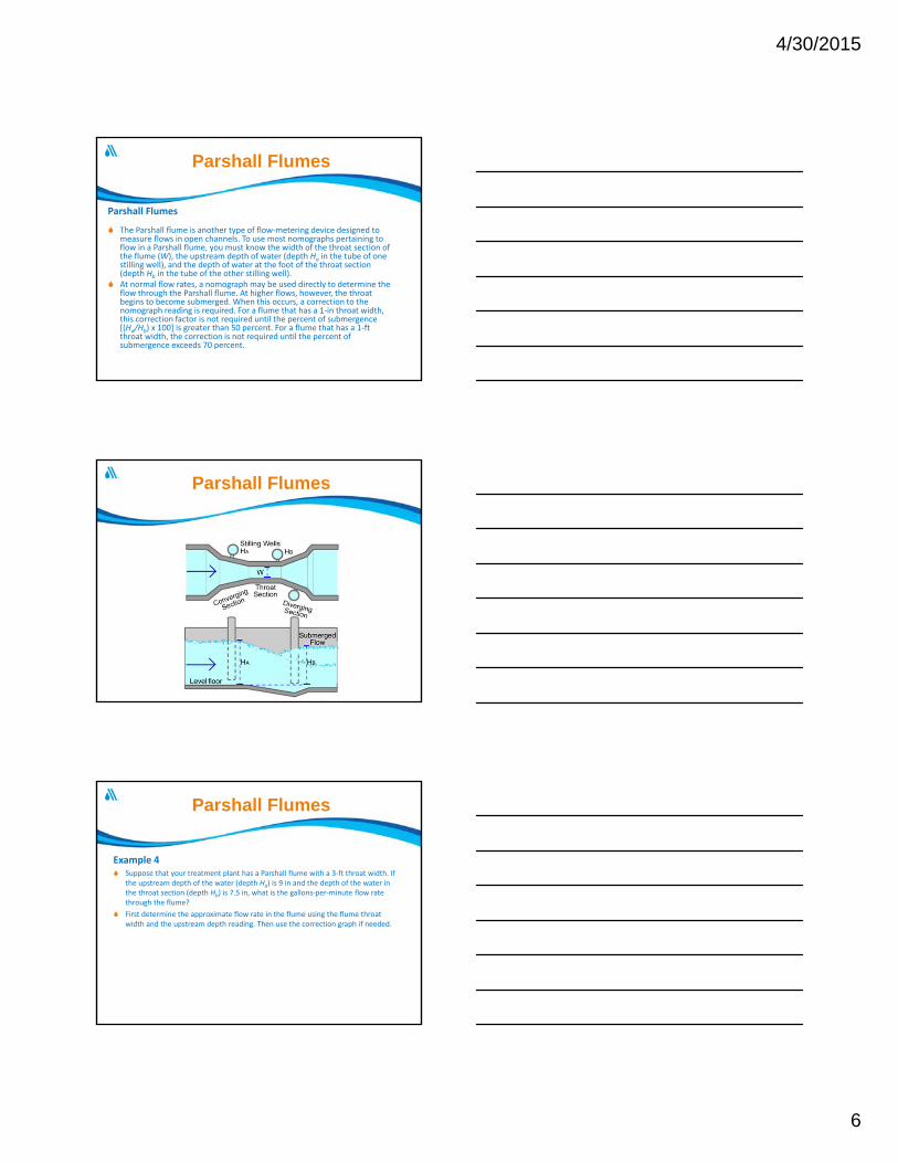
The Parshall flume is another type of flow‐metering device designed to measure flows in open channels. To use most nomographs pertaining to flow in a Parshall flume, you must know the width of the throat section of the flume (W), the upstream depth of water (depth Ha in the tube of one stilling well), and the depth of water at the foot of the throat section (depth Hb in the tube of the other stilling well).
At normal flow rates, a nomograph may be used directly to determine the flow through the Parshall flume. At higher flows, however, the throat begins to become submerged. When this occurs, a correction to the nomograph reading is required. For a flume that has a 1‐in throat width, this correction factor is not required until the percent of submergence [(Ha/Hb) x 100] is greater than 50 percent. For a flume that has a 1‐ft throat width, the correction is not required until the percent of submergence exceeds 70 percent.
Parshall Flumes
Parshall Flumes
Example 4 Suppose that your treatment plant has a Parshall flume with a 3‐ft throat width. If
the upstream depth of the water (depth Ha) is 9 in and the depth of the water in the throat section (depth Hb) is 7.5 in, what is the gallons‐per‐minute flow rate through the flume?
First determine the approximate flow rate in the flume using the flume throat width and the upstream depth reading. Then use the correction graph if needed.
Parshall Flumes
4/30/2015
7
Example 4
Example 4
Parshall Flumes
Example 4
Parshall Flumes

4/30/2015
8
Example 4
Parshall Flumes
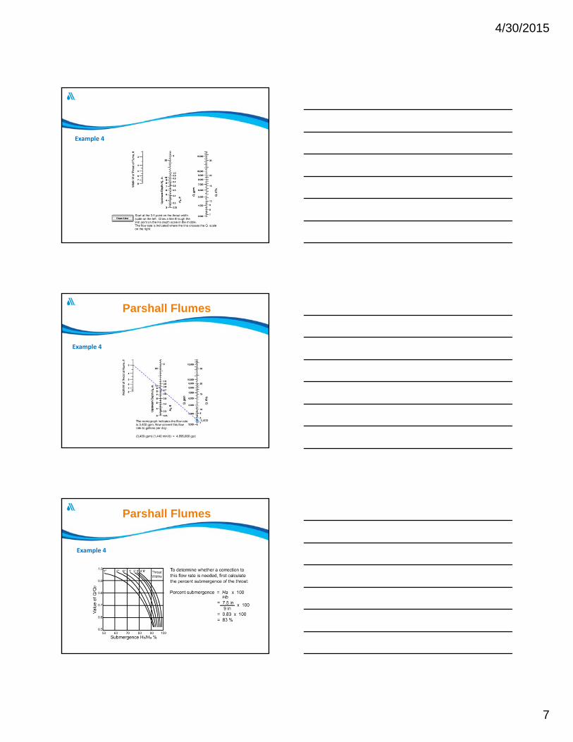
Example 4
Parshall Flumes
Example 4
Parshall Flumes
4/30/2015
9
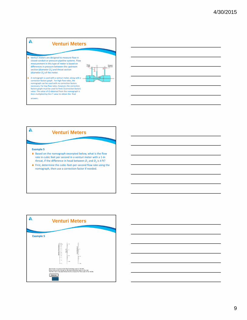
Venturi meters are designed to measure flow in closed‐conduit or pressure pipeline systems. Flow measurement in this type of meter is based on differences in pressure between the upstream section (diameter D1) and throat section (diameter D2) of the meter.
A nomograph is used with a venturi meter, along with a correction factors graph. For high flow rates, the nomograph can be used with no correction factors necessary. For low flow rates, however, the correction factors graph must be used to find C‘(correction factor) value. The value of Q obtained from the nomograph is then multiplied by the C' value to obtain the final
answer.
Venturi Meters
Example 5
Based on the nomograph excerpted below, what is the flow rate in cubic feet per second in a venturi meter with a 1‐in throat, if the difference in head between D1 and D2 is 4 ft?
First, determine the cubic‐feet‐per‐second flow rate using the nomograph, then use a correction factor if needed.
Venturi Meters
Example 5
Venturi Meters

4/30/2015
10
Example 5
Venturi Meters
Example 5
Venturi Meters
Example 5
Venturi Meters

4/30/2015
11
Orifice Meters
Orifice meters are another type of head differential meter designed for use in closed conduits. There is a pressure tap on each side of the orifice plate, and flow rate calculations are based on the difference in pressure between the upstream (high‐pressure) tap (D1) and the downstream (low‐pressure) tap (D2). A nomographcan be used to estimate the flow in orifice meters.
Orifice Meters
Example 6
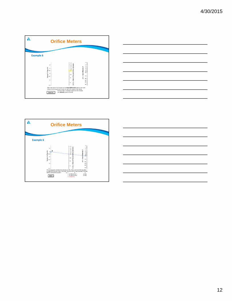
If the head differential between pressure taps 1 and 2 is 10.2 ft, the diameter of the pipe is 6 in, and the diameter of the orifice is 3 in, what is the flow rate in the pipeline in cubic feet per second?
First calculate the ratio of the pipe diameter to the orifice diameter and locate the result on the right side of the middle scale of the nomograph excerpted below.
Orifice Meters
Example 6
Orifice Meters
4/30/2015
12
Example 6
Orifice Meters
Example 6
Orifice Meters