Embed Size (px)
Citation preview
Basic Mechatronics WorkshopModule 1:Introduction to Mechatronics
Lecture-2Basic concepts of control systems
(Pilot & Memory, Sequence, Time Schedule)
1
Dr. Mohamed AbdalbarLecturer, Mechatronics Department,
Egyptian-Korean Faculty of Technological Industry and Energy,
Beni Suef Technological UniversityEmail: [email protected]
Objectives
Upon completion of this chapter, Student should be able to
1. Understand the basic concepts of control of systems.
2. Understand manual and automatic control operation
3. List the criteria for a working and control medium.
4. Understand Control types according to DIN 19226
5. Understand the basic concepts of pilot & memory, sequence, time schedule.
6. State the control system development.
Lecture-2Basic concepts of control systems
(Pilot & Memory, Sequence, Time Schedule)
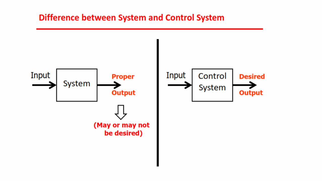
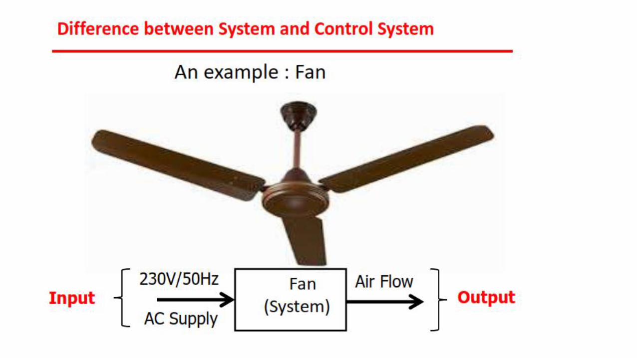
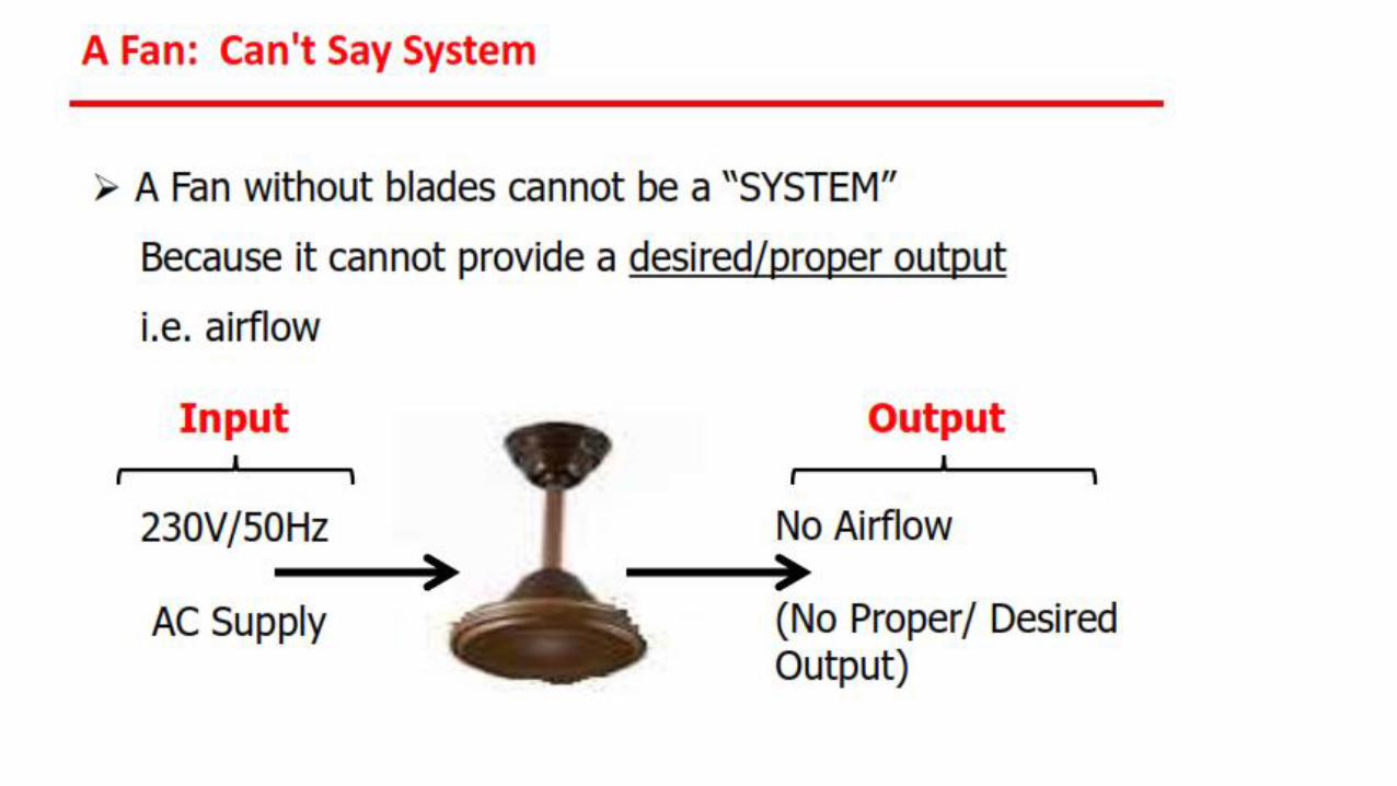
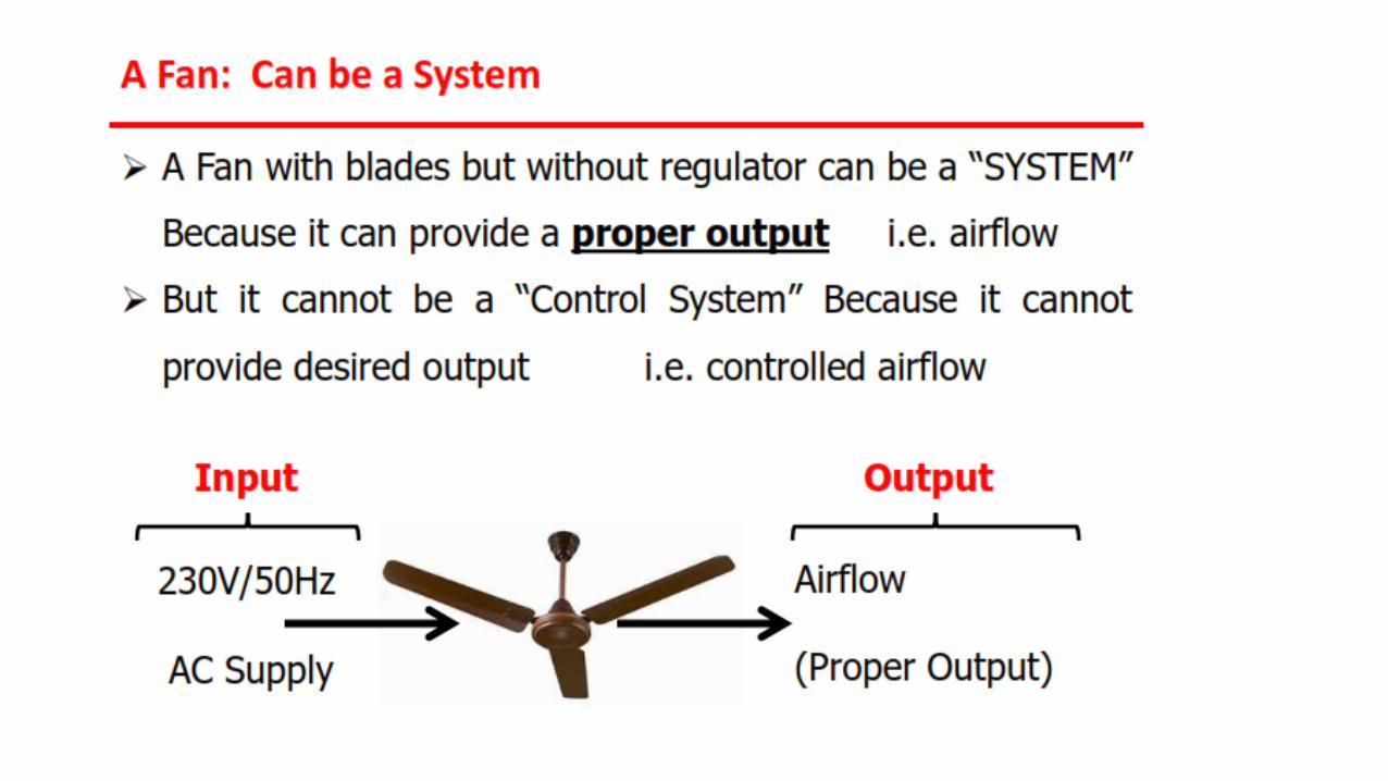
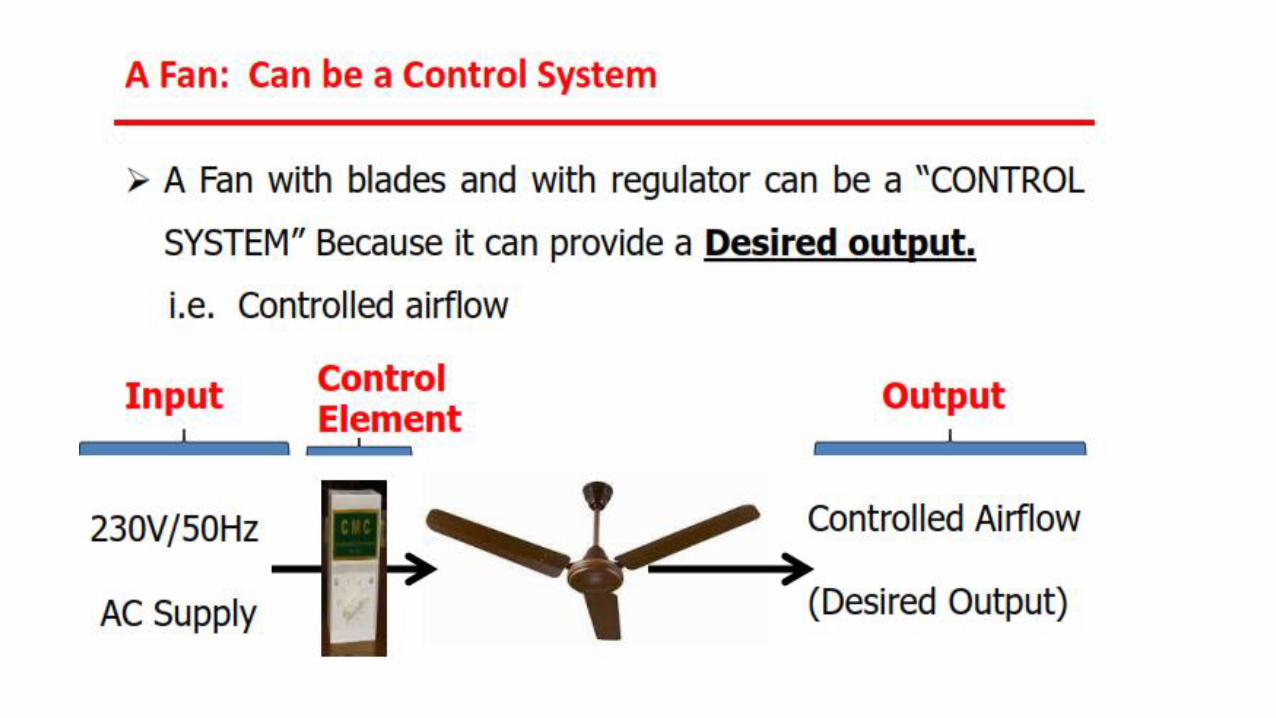
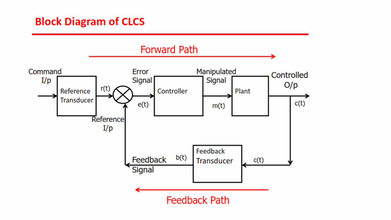
Control System Overview
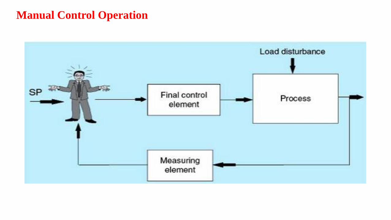
Manual Control Operation
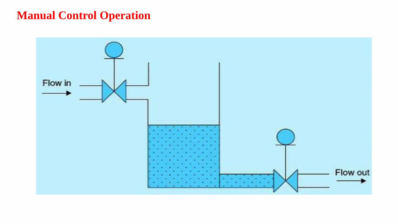
Manual Control Operation
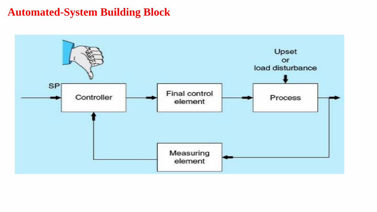
Automated-System Building Block
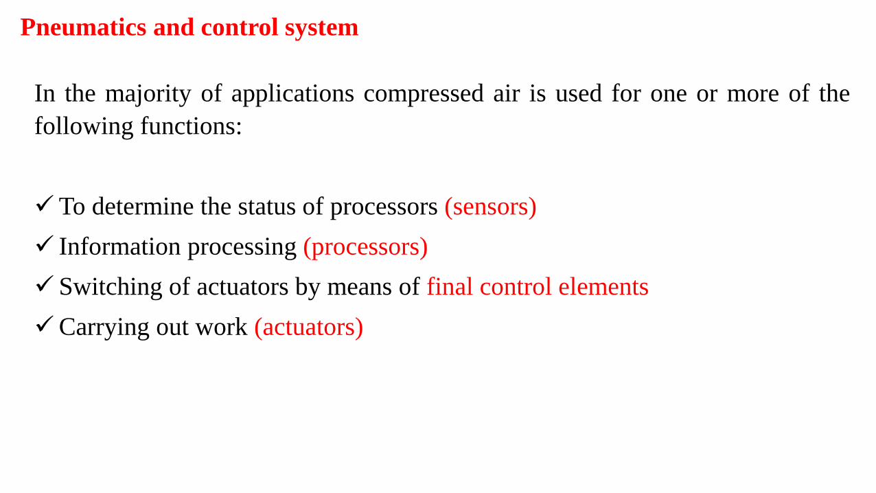
Pneumatics and control system
In the majority of applications compressed air is used for one or more of the
following functions:
✓To determine the status of processors (sensors)
✓ Information processing (processors)
✓ Switching of actuators by means of final control elements
✓Carrying out work (actuators)
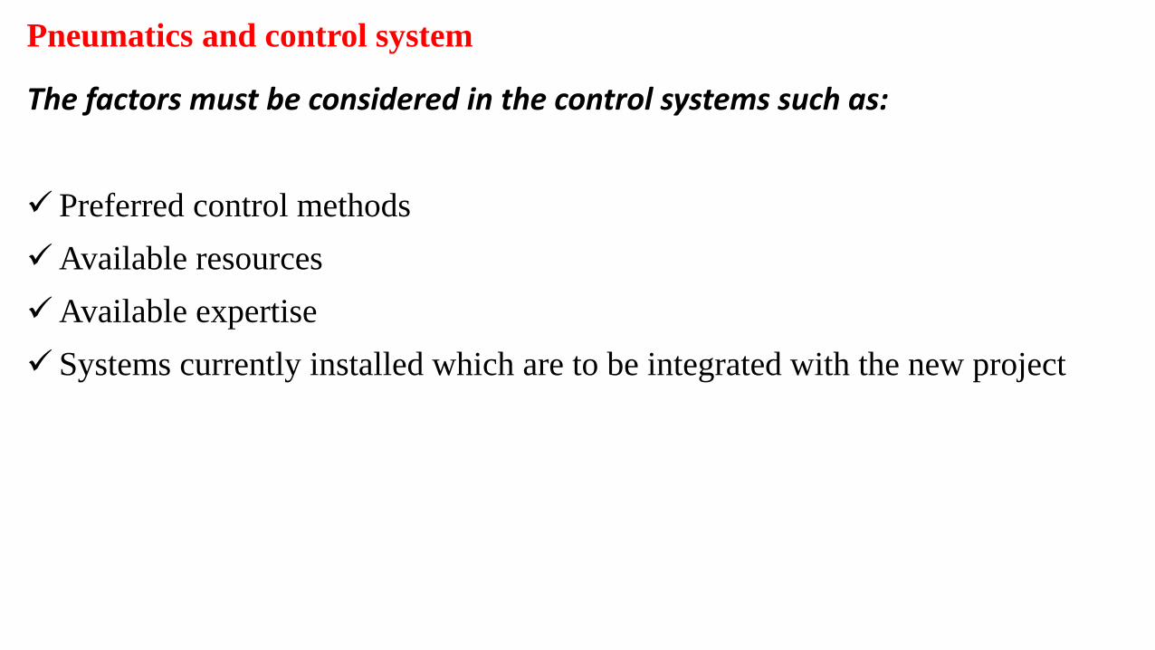
Pneumatics and control system
The factors must be considered in the control systems such as:
✓ Preferred control methods
✓Available resources
✓Available expertise
✓ Systems currently installed which are to be integrated with the new project
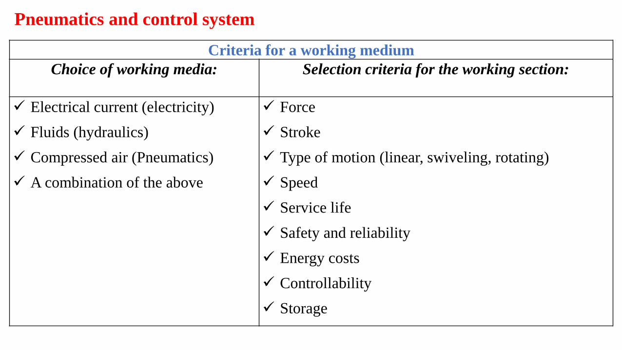
Pneumatics and control system
Criteria for a working medium
Choice of working media: Selection criteria for the working section:
✓ Electrical current (electricity)
✓ Fluids (hydraulics)
✓ Compressed air (Pneumatics)
✓ A combination of the above
✓ Force
✓ Stroke
✓ Type of motion (linear, swiveling, rotating)
✓ Speed
✓ Service life
✓ Safety and reliability
✓ Energy costs
✓ Controllability
✓ Storage
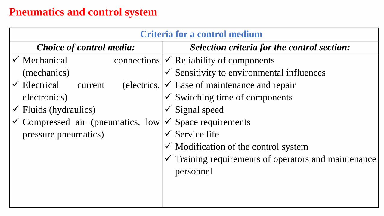
Pneumatics and control system
Criteria for a control medium
Choice of control media: Selection criteria for the control section:
✓ Mechanical connections
(mechanics)
✓ Electrical current (electrics,
electronics)
✓ Fluids (hydraulics)
✓ Compressed air (pneumatics, low
pressure pneumatics)
✓ Reliability of components
✓ Sensitivity to environmental influences
✓ Ease of maintenance and repair
✓ Switching time of components
✓ Signal speed
✓ Space requirements
✓ Service life
✓ Modification of the control system
✓ Training requirements of operators and maintenance
personnel
Pneumatics and control system
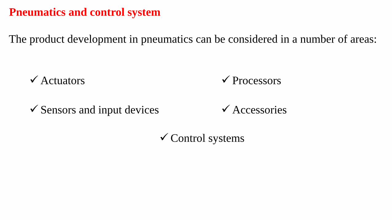
✓Actuators
✓ Sensors and input devices
✓ Processors
✓Accessories
✓Control systems
The product development in pneumatics can be considered in a number of areas:
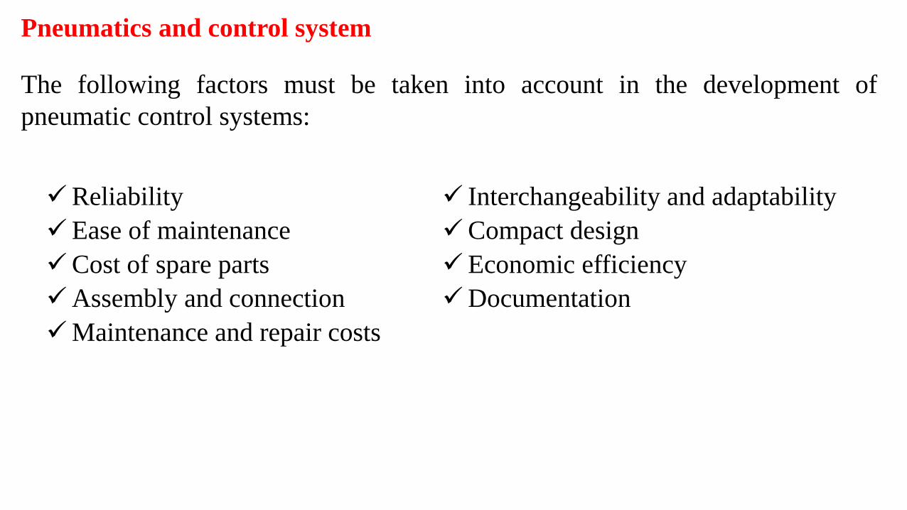
✓Reliability
✓Ease of maintenance
✓Cost of spare parts
✓Assembly and connection
✓Maintenance and repair costs
✓ Interchangeability and adaptability
✓Compact design
✓Economic efficiency
✓Documentation
The following factors must be taken into account in the development of
pneumatic control systems:
Pneumatics and control system
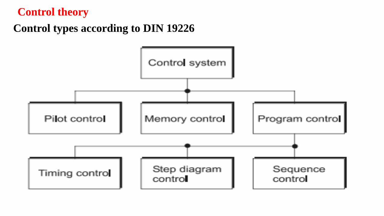
Control theory
Control types according to DIN 19226
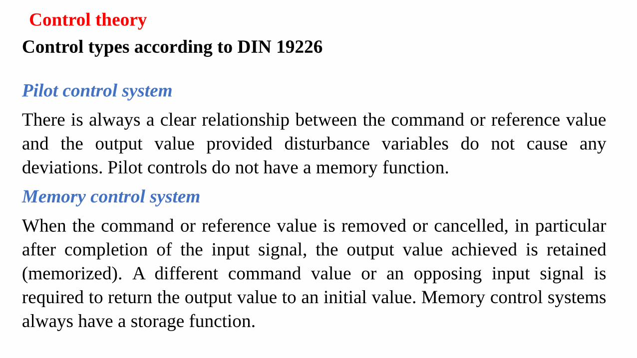
Control theory
Control types according to DIN 19226
Pilot control system
There is always a clear relationship between the command or reference value
and the output value provided disturbance variables do not cause any
deviations. Pilot controls do not have a memory function.
Memory control system
When the command or reference value is removed or cancelled, in particular
after completion of the input signal, the output value achieved is retained
(memorized). A different command value or an opposing input signal is
required to return the output value to an initial value. Memory control systems
always have a storage function.
Control theory
Control types according to DIN 19226
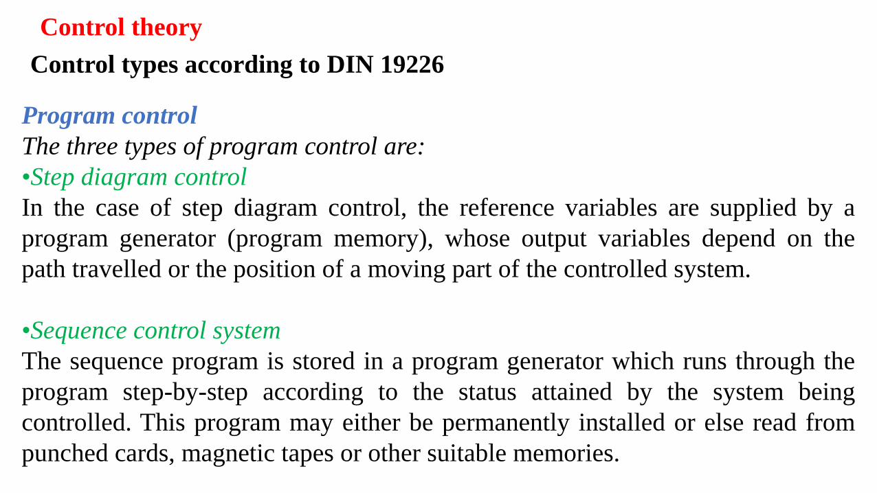
Program control
The three types of program control are:
•Step diagram control
In the case of step diagram control, the reference variables are supplied by a
program generator (program memory), whose output variables depend on the
path travelled or the position of a moving part of the controlled system.
•Sequence control system
The sequence program is stored in a program generator which runs through the
program step-by-step according to the status attained by the system being
controlled. This program may either be permanently installed or else read from
punched cards, magnetic tapes or other suitable memories.
Control theory
Control types according to DIN 19226
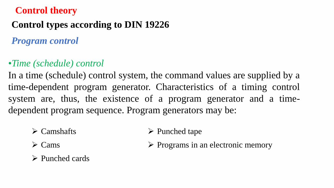
➢ Camshafts
➢ Cams
➢ Punched cards
➢ Punched tape
➢ Programs in an electronic memory
•Time (schedule) control
In a time (schedule) control system, the command values are supplied by a
time-dependent program generator. Characteristics of a timing control
system are, thus, the existence of a program generator and a time-
dependent program sequence. Program generators may be:
Program control
Control theory
Control system types
Differentiation between the control systems can be made on the basis of different
viewpoints. According to these standard, distinguishing features for control
systems are in the form of the representation of information and in the form of
signal processing.
✓Form of information representation
✓Form of signal processing
Control theory
Control system types Form of information representation
Control theory
Control system types
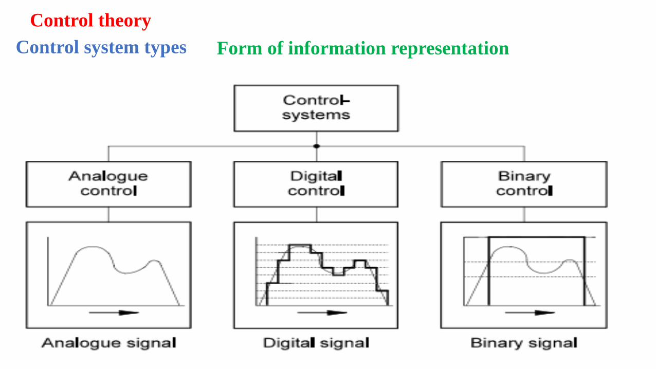
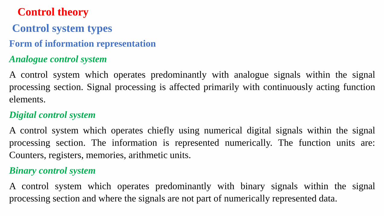
Form of information representation
Analogue control system
A control system which operates predominantly with analogue signals within the signal
processing section. Signal processing is affected primarily with continuously acting function
elements.
Digital control system
A control system which operates chiefly using numerical digital signals within the signal
processing section. The information is represented numerically. The function units are:
Counters, registers, memories, arithmetic units.
Binary control system
A control system which operates predominantly with binary signals within the signal
processing section and where the signals are not part of numerically represented data.
Control theory
Control system types Form of signal processing
Control theory
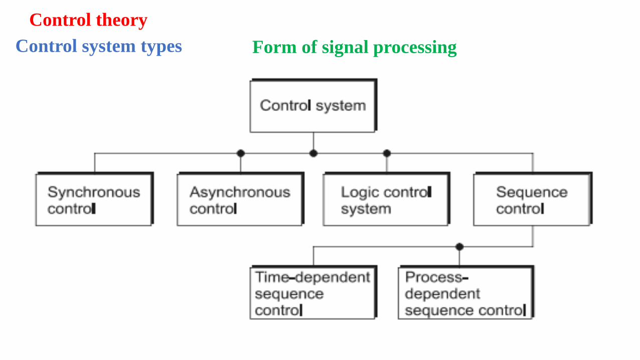
Control system types
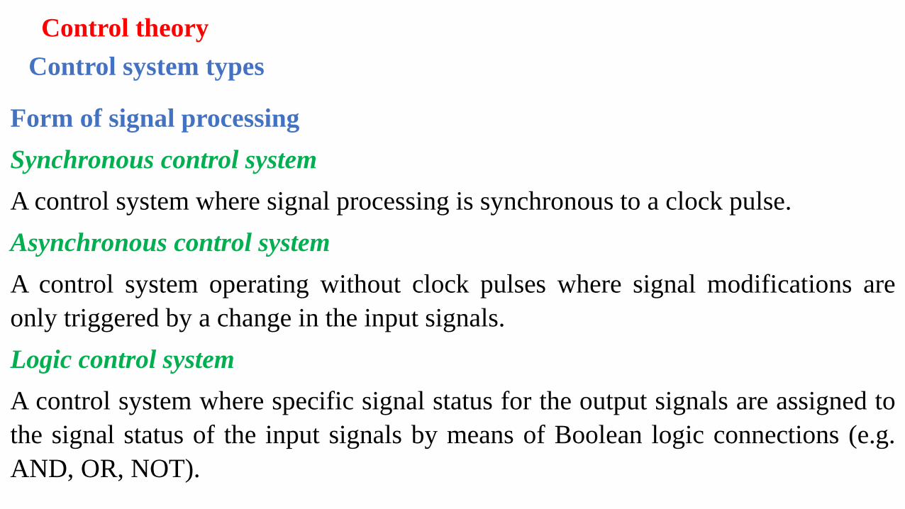
Form of signal processing
Synchronous control system
A control system where signal processing is synchronous to a clock pulse.
Asynchronous control system
A control system operating without clock pulses where signal modifications are
only triggered by a change in the input signals.
Logic control system
A control system where specific signal status for the output signals are assigned to
the signal status of the input signals by means of Boolean logic connections (e.g.
AND, OR, NOT).
Control theory
Control system types
Form of signal processing
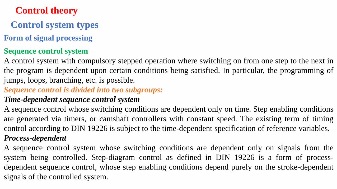
Sequence control system
A control system with compulsory stepped operation where switching on from one step to the next in
the program is dependent upon certain conditions being satisfied. In particular, the programming of
jumps, loops, branching, etc. is possible.
Sequence control is divided into two subgroups:
Time-dependent sequence control system
A sequence control whose switching conditions are dependent only on time. Step enabling conditions
are generated via timers, or camshaft controllers with constant speed. The existing term of timing
control according to DIN 19226 is subject to the time-dependent specification of reference variables.
Process-dependent
A sequence control system whose switching conditions are dependent only on signals from the
system being controlled. Step-diagram control as defined in DIN 19226 is a form of process-
dependent sequence control, whose step enabling conditions depend purely on the stroke-dependent
signals of the controlled system.
Control theory
Control system development
✓ Positional sketch
✓Displacement-step diagram
✓Control chart
✓ Function diagram
✓ Function chart
✓Circuit diagram
The development of the control system solution requires that the problem is
defined clearly. There are many ways of representing the problem in a
descriptive or graphical form. The methods of representing the control
problem include:
Control theory
Control system development Positional sketch
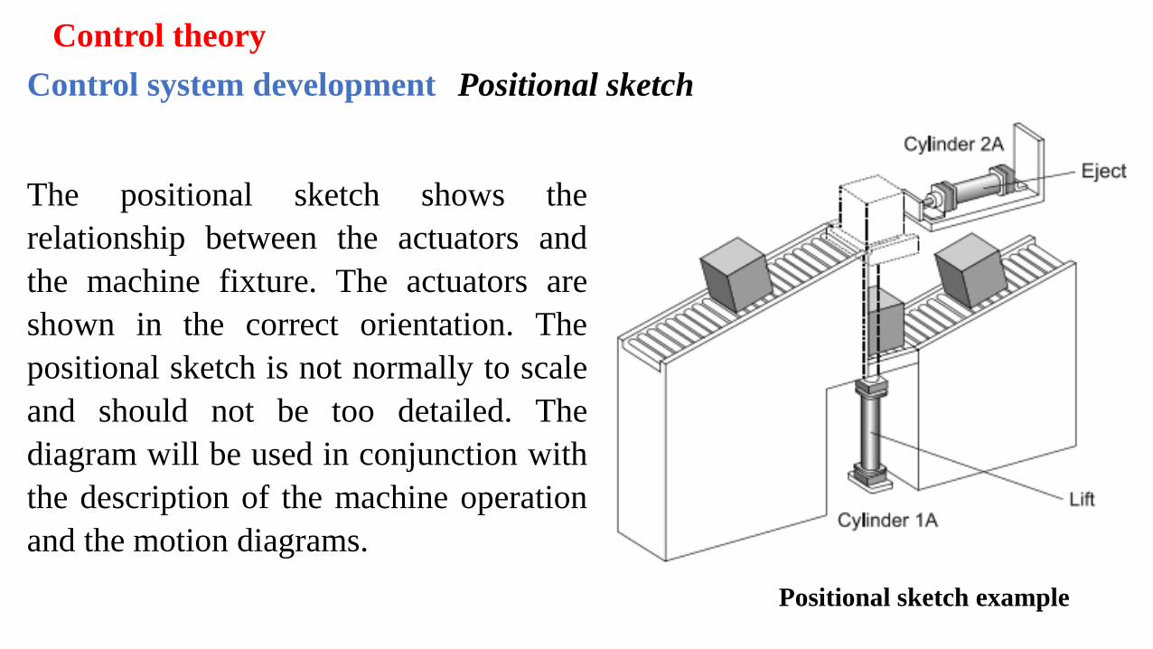
Positional sketch example
The positional sketch shows the
relationship between the actuators and
the machine fixture. The actuators are
shown in the correct orientation. The
positional sketch is not normally to scale
and should not be too detailed. The
diagram will be used in conjunction with
the description of the machine operation
and the motion diagrams.
Control theory
Control system development Displacement-step diagram
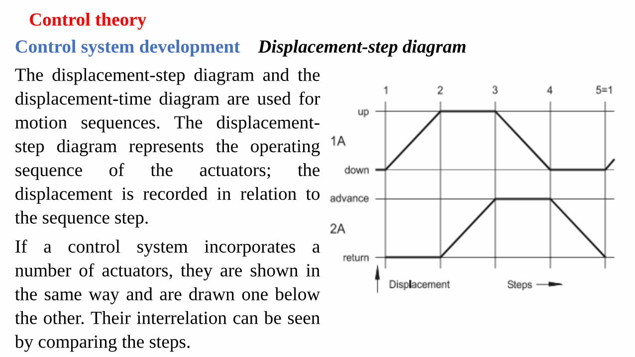
The displacement-step diagram and the
displacement-time diagram are used for
motion sequences. The displacement-
step diagram represents the operating
sequence of the actuators; the
displacement is recorded in relation to
the sequence step.
If a control system incorporates a
number of actuators, they are shown in
the same way and are drawn one below
the other. Their interrelation can be seen
by comparing the steps.
Control theory
Control system development Displacement-time diagram
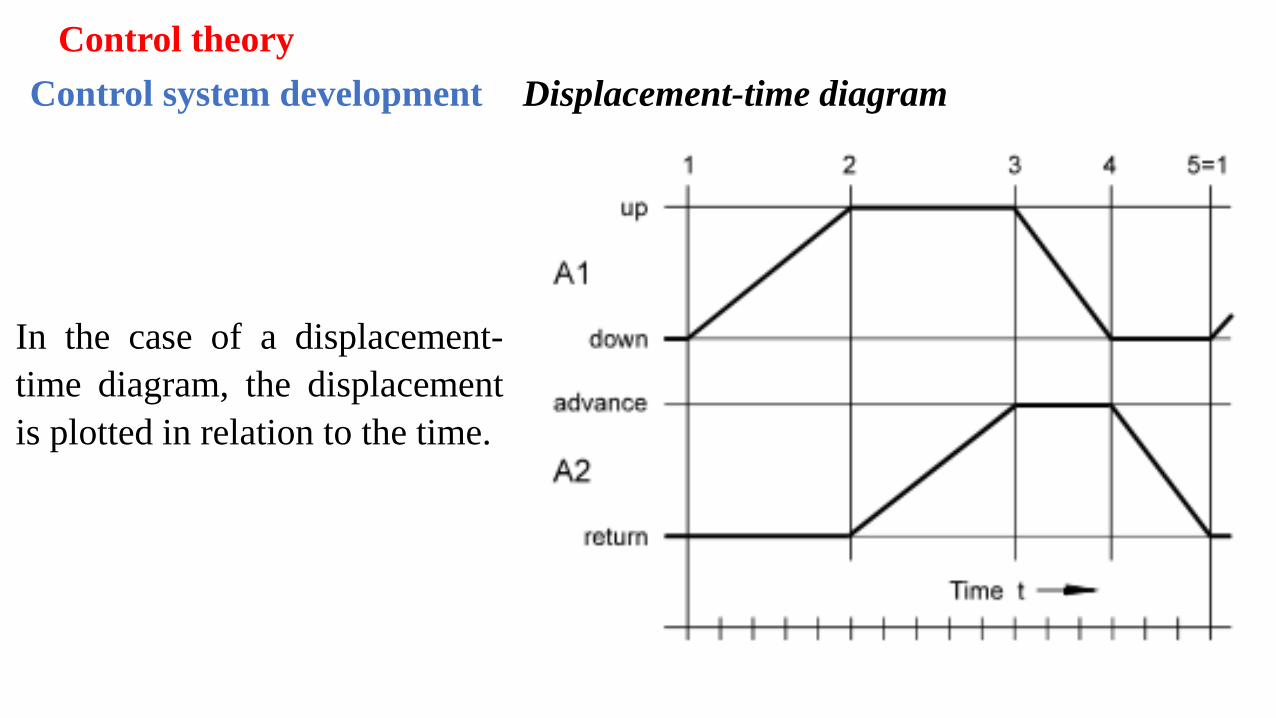
In the case of a displacement-
time diagram, the displacement
is plotted in relation to the time.
Control theory
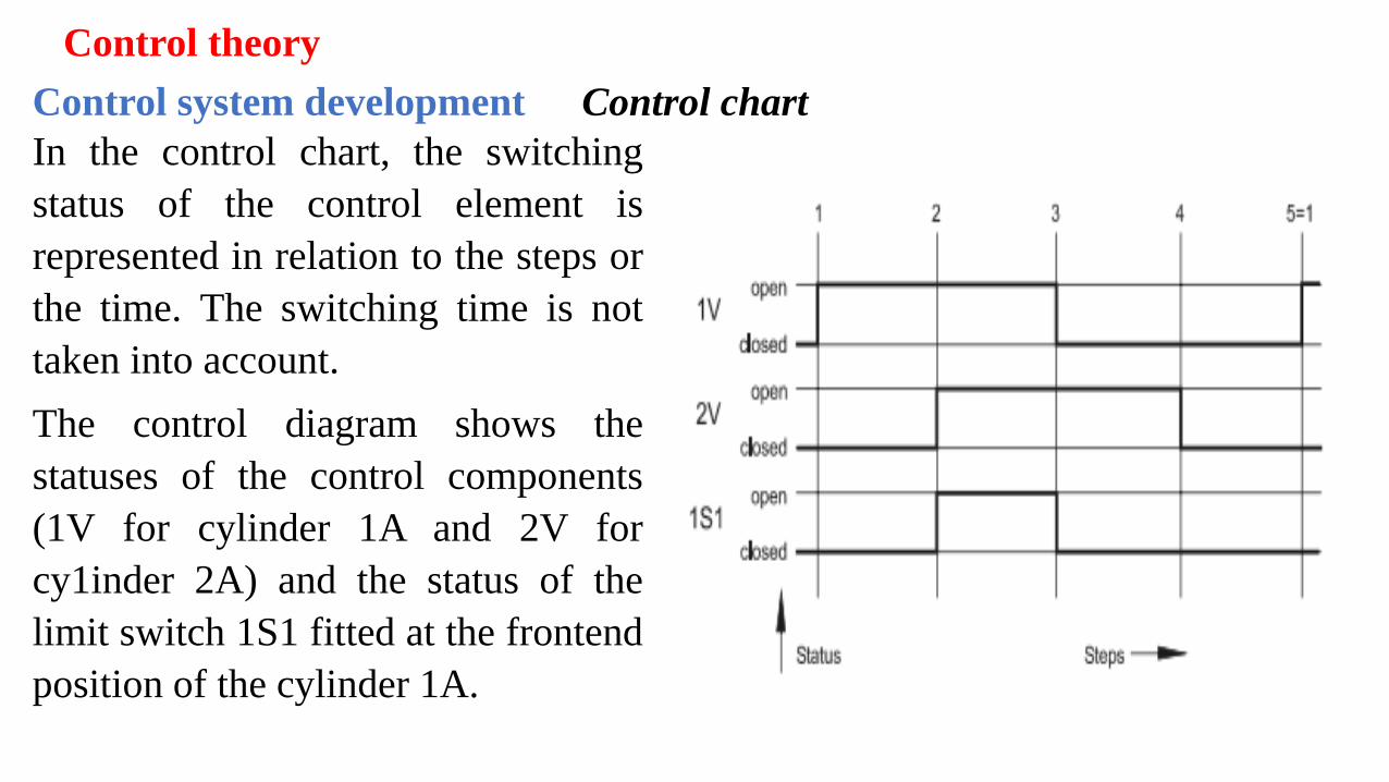
Control system development Control chart
In the control chart, the switching
status of the control element is
represented in relation to the steps or
the time. The switching time is not
taken into account.
The control diagram shows the
statuses of the control components
(1V for cylinder 1A and 2V for
cy1inder 2A) and the status of the
limit switch 1S1 fitted at the frontend
position of the cylinder 1A.
Control theory
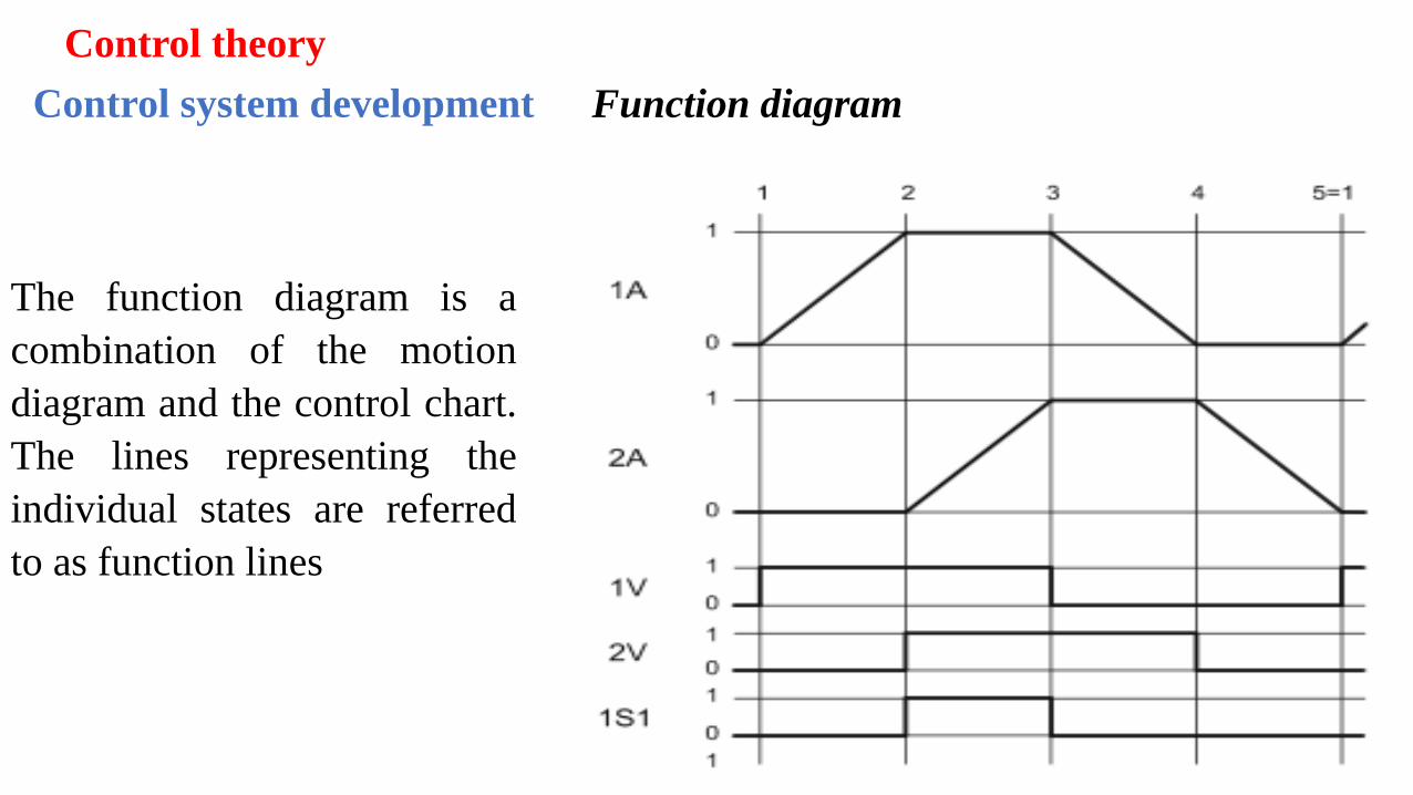
Control system development Function diagram
The function diagram is a
combination of the motion
diagram and the control chart.
The lines representing the
individual states are referred
to as function lines
Control theory
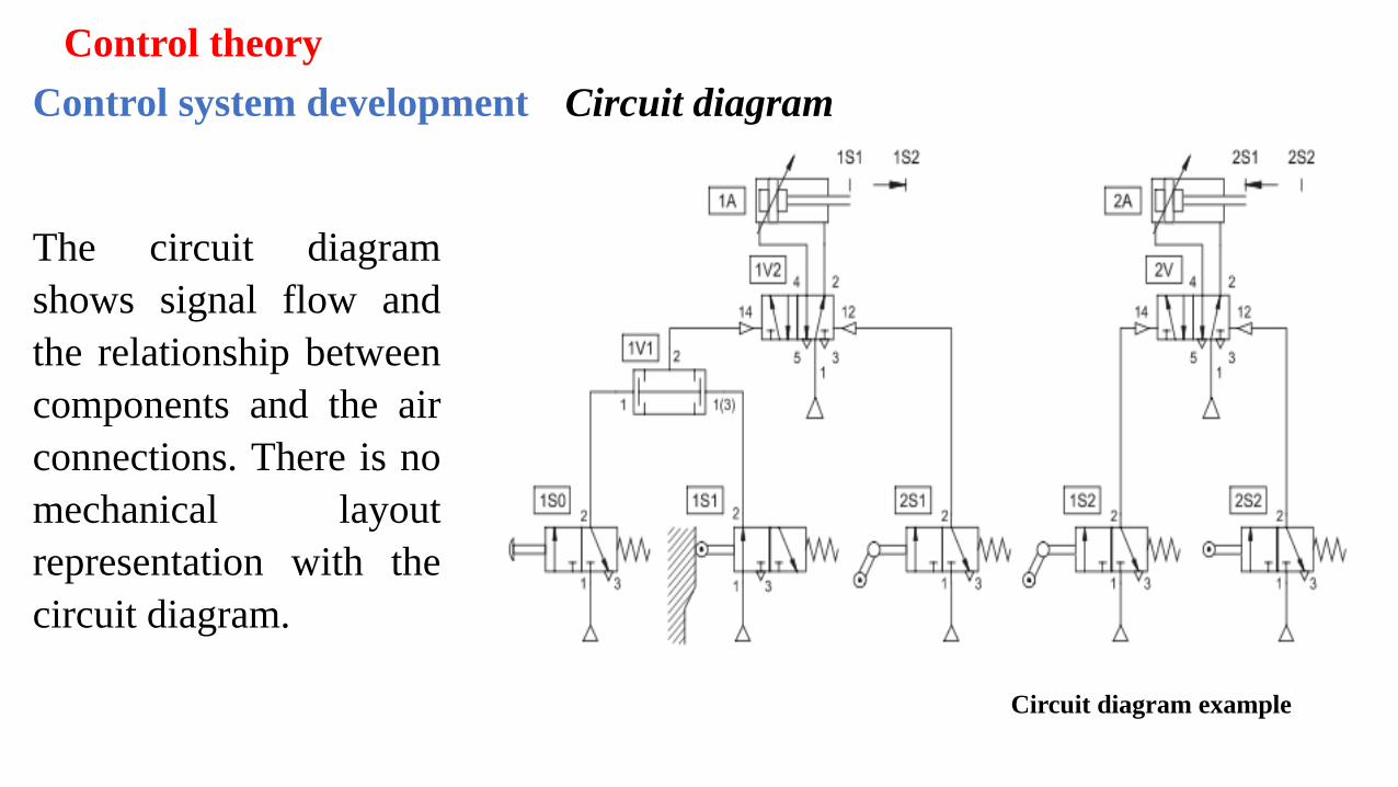
Control system development Circuit diagram
The circuit diagram
shows signal flow and
the relationship between
components and the air
connections. There is no
mechanical layout
representation with the
circuit diagram.
Circuit diagram example