Embed Size (px)
Citation preview

Module 8 : Laser- IILecture : Laser- I
Part-I
Objectives In this lecture you will learn the following
Maser
Rate Equations for a Two Level System
Three Level Laser
Rate Equations for a Three Level System
Four Level Laser
Rate Equations for a Four Level System
Fabry - Perot Cavity and Laser Oscillation
Gain Saturation
Properties of Laser Beam
Spatial Coherence
2.7 MASER:
The frequency of microwave photons is Hz, corresponding to an energy of the order of0.01 eV. The energy is of the same order as that of the thermal energy of air molecules. Insuch a case, the population of the excited states is comparable to that of the ground stateat room temperatures. The process of stimulated emission can then be used to amplifymicrowave signal. MASER is an acronym for Microwave Amplification by StimulatedEmission of Radiation .
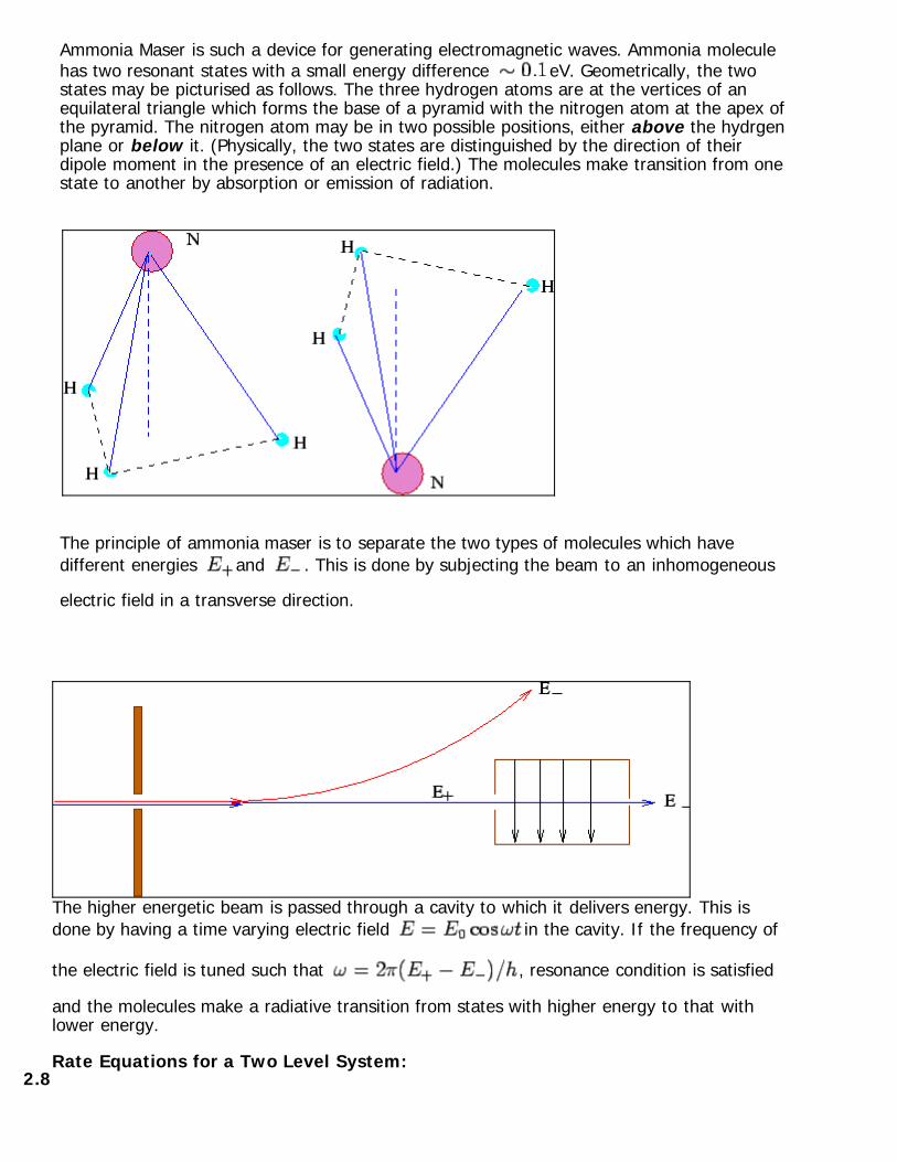
Ammonia Maser is such a device for generating electromagnetic waves. Ammonia moleculehas two resonant states with a small energy difference eV. Geometrically, the twostates may be picturised as follows. The three hydrogen atoms are at the vertices of anequilateral triangle which forms the base of a pyramid with the nitrogen atom at the apex ofthe pyramid. The nitrogen atom may be in two possible positions, either above the hydrgenplane or below it. (Physically, the two states are distinguished by the direction of theirdipole moment in the presence of an electric field.) The molecules make transition from onestate to another by absorption or emission of radiation.
The principle of ammonia maser is to separate the two types of molecules which havedifferent energies and . This is done by subjecting the beam to an inhomogeneous
electric field in a transverse direction.
The higher energetic beam is passed through a cavity to which it delivers energy. This isdone by having a time varying electric field in the cavity. If the frequency of
the electric field is tuned such that , resonance condition is satisfied
and the molecules make a radiative transition from states with higher energy to that withlower energy.
2.8Rate Equations for a Two Level System:

Consider a two level system with the upper level and the ground level . In order that
laser transition may occur, we need a population inversion. As at normal temperatures, thepopulation of lower level is more than that at the upper level, atoms must be pumped intothe upper level by providing them energy equal to the energy difference between the twolevels.
If is the pumping induced transition rate for or and is the natural
lifetime of atoms in the upper level, the rate equation for the two levels may be written asfollows :
where . In the steady state, the time derivatives vanish, and
we have
In order that a population inversion may take place, we must have . However,
one sees that as the intensity is increased the population in the upper level at bestapproaches this number as its maximum. Thus population inversion is not possible ina two level system.
2.9
Three Level Laser:
For optical frequencies, population inversion cannot be achieved in a two level system. In1956 Bloembergen proposed a mechanism in which atoms are pumped into an excitedstate by an external source of energy ( such as by an electric pulse or by opticalillumination).

The system, in addition to the state , has an excited state which is a metastablestate, i.e. a state in which the atom has a long life time. Atoms from the upperlevel decays spontaneously to this metastable state . Life time in the level is such that therate of spontaneous decay from level to the ground level is slower than the rate at
which atoms decay from to . This results in a population inversion between themetastable level and the ground state.
The emitted photons are confined to a laser cavity to stimulate further emission from theexcited atoms. Ruby laser works on the principle of a three level system. The pumpingpower required for such a system is very high because more than half of the ground stateatoms have to be pumped into the upper level to achieve population inversion.
A few additional points to be noted about the three level system are :
As and , once the population inversion is achieved,

the power required to maintain it is small.
transition is generally radiationless, the energy being given away to the lattice.
As more than half of the atoms are to be raised to the level , the probability ofspontaneous emission is also much higher.
Laser transition occurs from the metastable state to the lowest possible state which arewell separated. This leads to low efficiency.
2.9.1Rate Equations for a Three Level System :
In a three level system, the laser transition is from the metastable state to the groundstate . In the following analysis, we will ignore the effects of degeneracy.
As in the case of two level system, we denote by , the transition rate induced by
pumping from the ground state ( ) to the top level or vice versa. is clearly
proportional to the pumping rate. As the metastable state is long lived, we assume that is much smaller than either or , where denotes the lifetime of transition
. As a result, the population of the upper level is nearly zero, and correspondingly,
The rate equation for the level may be written as

the equation for the metastable level is
The rate equation for the ground state is obtained from the above two equations by numberconservation
In the steady state, each of the time derivatives is zero, which gives
The equation for population inversion becomes
where
For population inversion to occur, the numerator of eqn. (A) must be positive, , i.e.,

From (B), as the lifetime for transition is longer than that for
transition. Thus is a sufficient condition for population inversion. A minimum
pumping power determined by (C) is required to ensure population inversion. For ,
As is ground level, its value is initially very large and at least atoms must be
transferred to the upper level achieve population inversion. Hence a three level system is notvery energy efficient.
2.10Four Level Laser :
One of the most popular and low cost lasers is helium-neon laser, which works on the basisof a four level system with two levels intermediate between the ground state and the
pumpng level .
The ground state atoms are electrically pumped to a short lived state . Atoms from this
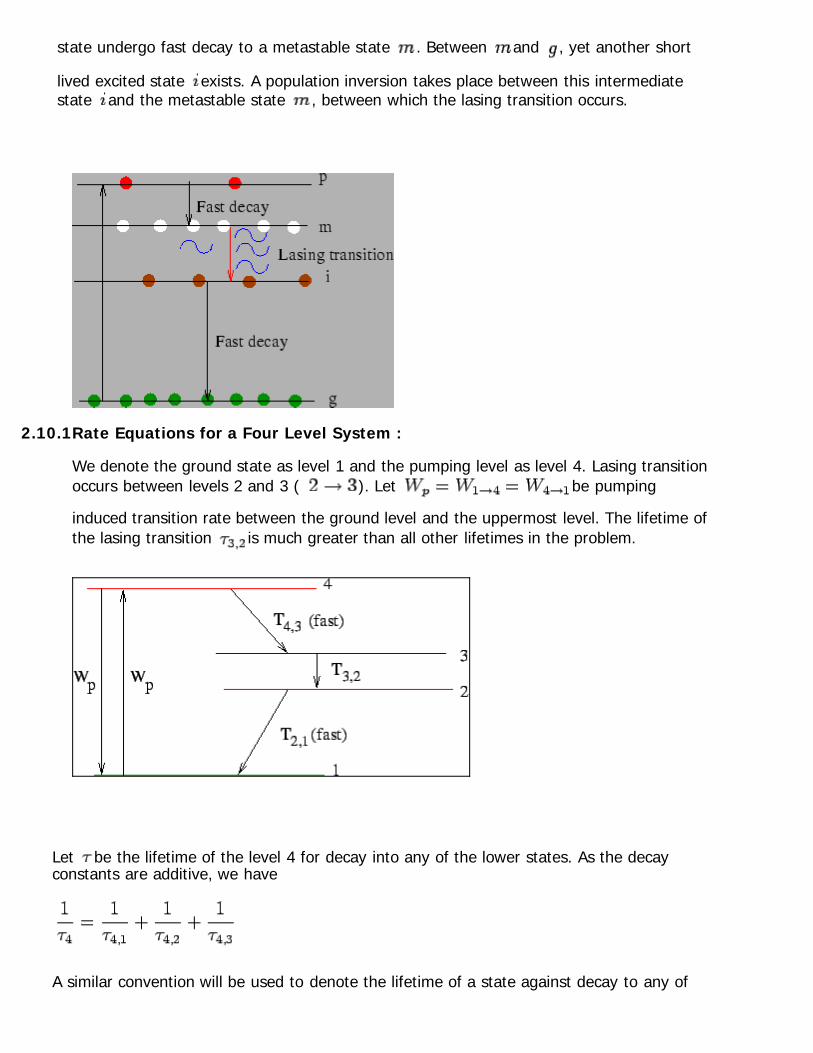
state undergo fast decay to a metastable state . Between and , yet another short
lived excited state exists. A population inversion takes place between this intermediatestate and the metastable state , between which the lasing transition occurs.
2.10.1Rate Equations for a Four Level System :
We denote the ground state as level 1 and the pumping level as level 4. Lasing transitionoccurs between levels 2 and 3 ( ). Let be pumping
induced transition rate between the ground level and the uppermost level. The lifetime ofthe lasing transition is much greater than all other lifetimes in the problem.
Let be the lifetime of the level 4 for decay into any of the lower states. As the decayconstants are additive, we have
A similar convention will be used to denote the lifetime of a state against decay to any of
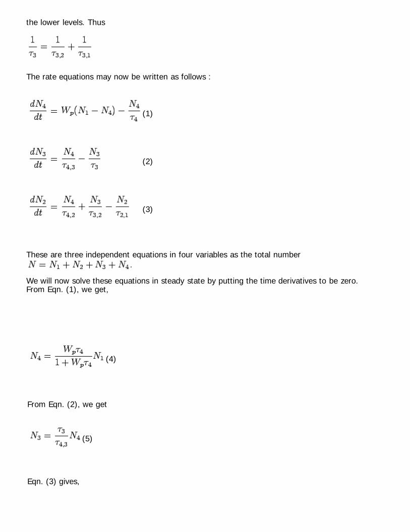
the lower levels. Thus
The rate equations may now be written as follows :
(1)
(2)
(3)
These are three independent equations in four variables as the total number .
We will now solve these equations in steady state by putting the time derivatives to be zero.From Eqn. (1), we get,
(4)
From Eqn. (2), we get
(5)
Eqn. (3) gives,

(6)
where
(7)
If , there will be more population in the upper laser level than in the lower one,
leading to a population inversion. Using the above, and after straight forwardsimplification, we get
and the population difference given by
Combining the above two equations
Let us define Quantum Efficiency as the fraction of atoms excited from the ground
state (1) which ultimately results in stimulated emission. is thus a product of the fraction
which arrives at the upper laser level (3) and the fraction of atoms in the upper laser levelwhich make radiative transition to the lower laser level (2).

Fraction of atoms in level 4 which arrive at level 3 is given by the ratio and the
fraction of atoms in level 3 which radiatively make a transition to level 2 is . We
have used a superscript rad to indicate that only the radiative component of the transitionfrom 3 to 2 is considered. Thus
Substituting this in the previous equation, we get, for
To ensure that most of the atoms excited by pumping participate in laser transition, the lifetime in the level 3 must be the longest. Using , we may ignore this term in the
denominator of the above. Further, . Using these, one can see that is small
and approaches zero.
Thus ramains positive and population inversion occurs even for very small pumping
power. For , the expression for is given by

2.11Fabry - Perot Cavity and Laser Oscillation:
Optical resonators play an important role in amplifying laser beam. Fabry-Perot resonators (etalons ) are optical cavities which are used for the purpose. A simple Fabry-Perot etalon consists of two partially reflecting parallel mirrors withreflectances and separated by a length . For simplicity, consider an
electromagnetic wave of amplitude incident normally on one of the faces of the etalon.
The ray sufferes multiple reflection, bouncing to and fro between the mirrors. At eachreflection, the field amplitude gets reduced by a factor or as the
case may be.
In addition, if the wave vector of the field is , the wave suffers a phase change (thisis in addition to the phase change due to reflection) If and are the transmission
coefficients of the mirror, the transmitted amplitude is given by
The transmitted intensity is given by

where and are the transmittance. If the reflectances of both the mirrors are the
same, and, using , we have
is called finesse . is known as Airy function . For
non-normal incidence, a similar expression is valid with being replaced by where is the angle of incidence. The intensity pattern for three values of reflectance isshown.

Note that at the resonance, i.e., when , the transmission intensity is maximum.The FWHM of the intensity pattern can be obtained by looking at any of the peaks sincethe shape of intensity function repeats itself. Consider the peak near . For largevalues of , the peak is very sharp and we may replace by itself. Thus FWHMis given by
which gives , so that FWHM is .
A Fabry-Perot cavity can, therefore, be used to select wavelength by suitably adjusting themirror separation, the wavelengths at which resonances occur are given by
where are integers. As increases, the wavelengths decrease. Using the speed of light
in the medium to be , where is the refractive index of the medium, the resonance
frequencies are
which are eqi-spaced. Each possible standing wave satisfying the above is called a cavitymode being the mode number .
If now, an active medium with a gain coefficient is put inside the Fabry-Perot cavity, in
one round trip the optical power is
Optical amplification occurs if , i.e., if
The righthand side of the above is termed threshold gain .

2.12Gain Saturation:
Clearly, gain cannot continue indefinitely. For each photon added to the field, one atom isremoved from the upper laser level and one is added to the lower level. Thus populationinversion reduces, which in turn, reduces gain. There is a competition between pumpingand stimulated emission rate. Pumping builds up population of the upper level till thresholdis reached and stimulated emission starts. Let us consider a simple rate equation for the population of the upper level. Let be the
number density of photons per unit time. In a gain medium . The population
of the upper level is given by
where, is the pumping rate to the upper level, is the natural lifetime of the excited
atoms and is the gain cross section.
In the absence of stimulated emission , so that the population in the steady state isguven by
The population reaches the steady state in an exponential fashion
In the presence of light, the steady state solution to equation (A) is obtained by equatingthe right hand side of (A) to zero. The steady state population of the upper level is given

by
We may rewrite the above as
where is the saturation intensity, which is equal to the intensity for which the gain is
reduced by a factor of 2.
2.13Properties of Laser Beam:
Laser beams are characterized by the following special properties :Coherence: Laser beam is highly coherent, i.e, different parts of the beam maintain aphase relationship bfor a long time. this results in interference effect. When a laser beamreflects off a surface, the reflected light can be seen to have bright regions separated bydark regions. Temporal Coherence: One can define a coherence time after which the phase correlation between twowaves which were initially in phase ( or between two points in the same wave which had aknown phase difference) drops significantly. The reason for loss of coherence is than an optical source does not emit a continuouswave for all time to come. Thermal sources, for instance, have a typical life time of
seconds so thata wave which seems continuous, actually consists of asequence of waves which are typically m long which no phase correlationbetween parts of one wave train and another. Temporal coherence is essentially a measure of monochromaticity of the beam. To see thisconsider a wave train which is emitted for a finite duration. Let the wave disturbance berepresented by
The wave is not strictly monochromatics, as would have been the case if the wave trainwas for indefinite duration. The spread in frequency in the wave is found by taking aFourier transform of the wave train,
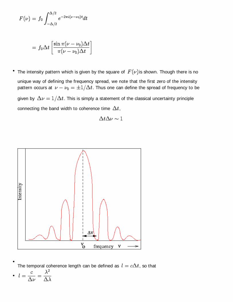
The intensity pattern which is given by the square of is shown. Though there is no
unique way of defining the frequency spread, we note that the first zero of the intensitypattern occurs at . Thus one can define the spread of frequency to be
given by . This is simply a statement of the classical uncertainty principle
connecting the band width to coherence time ,
The temporal coherence length can be defined as , so that

where is the mean wavelength and is the spread of wavelengths about this mean,which is also a measure of the degree of monochromaticity of the wave.
Exercise : A He-Ne laser operating at 630 nm has an emission width of nm. Calculate the
temporal coherence length.(Ans. 400 m) It may be noted that a laser beam is highly monochromatic with the spread of wavelengthbeing very small.
Exercise:
An Argon laser operating in single mode has a linewidth of 7.5 MHz. Calculate its coherencelength. (Ans. 40 m)
Spatial Coherence: Spatial coherence describes the distance over which phase correlation exists between
different points in the same wave in a direction perpendicular to the direction of observation.Spatial correlation arises because a source is never really a point source. Consider two point
sources S and S at a distance from each other along the y-axis, as shown.
Suppose the waves arriving at the point P which is at a distance along the directionperpendicular to the line joining the sources are coherent. The phase difference betweenwaves arriving at the point Q which is at a lateral distance is . Using
straightforward geometry, we can see that the path difference is given by
We may arbitrarily define the spatial coherence length to be the lateral distance atwhich the waves are out of phase by . Thus
The spatial coherence length is given by

Using the above argument, if we have a source of circular shape of diameter , thelateral coherence length is
As an illustration, we note that a source of 100 m diameter emitting at 100 nm has
a spatial coherence length of m.
Directionality: Laser beam is highly collimated and can travel long distances withoutsignificant spread in the beam cross section. As the collimated beam propagates, thebeam spreads out. The full angle beam divergence is defined as the amount by
which the beam diameter (D) increases over a distance after leaving the source
Taking the beam profile to be gaussian, the intensity varies as , where is the
distance from the centre of the beam where the intensity ( ) is maximum. We define
beam radius as the radial distance over which the intensity decreases by a factor from its maximum value at the centre. Thus nearly 94% of the energy is
concentrated within the beam radius.
The angular divergence of the beam is given by
where is the radius of the beam at the point where the beam leaves the laser. The
radius of the beam varies with the distance as
where .

Example: A 10 mW He-Ne laser operating at 633 nm has a spot size of 10mm. Assuming a Gaussian
beam find the beam radius and intensity at a distance of 100m from the source.
Solution:
The beam radius is half the spot size. The beam divergence (half angle) is given by
The radius increases with distance as
Area of the spot is (mm) . The intensity of the spot =
W/m .

Recap In this lecture you have learnt the following
Maser
Rate Equations for a Two Level System
Three Level Laser
Rate Equations for a Three Level System
Four Level Laser
Rate Equations for a Four Level System
Fabry - Perot Cavity and Laser Oscillation
Gain Saturation
Properties of Laser Beam
Spatial Coherence
Part-II
Objectives In this lecture you will learn the following
Types of Lasers and Applications
Helium-Neon Laser
Carbon dioxide Laser
Argon-ion Laser
Semiconductor Lasers
Homojunction Laser (Laser Diode)

Heterojunction Laser
Properties of GaAs Laser
Vertical Surface Emitting Laser
Noise in a Laser Source
2.14 Types of Lasers and Applications: Lasers have found wide applications in areas as diverse as optical communications,
medical surgery, welding technology, entertainment electronics etc. What makes suchveritable use of lasers possible is the highly collimated nature of the laser beams and theconsequent possibility of delivering a very high energy density in a limited region ofspace. Depending on the material used for the active medium , lasers are broadlyclassified as (i) conventional or gas lasers (ii) solid state lasers (iii) liquid lasers and (iv)semiconductor lasers. Among the gas lasers, some of the most commonly used ones areHelium - Neon laser, Carbon dioxide laser and Argon- ion laser.
2.14.1Helium-Neon Laser:
Helium-neon laser consists of an active medium of a gas mixture with about 80% He and20% Ne, kept in a glass chamber at at low pressure. The ends of the chamber aresilvered with one end having a perfectly reflecting mirror while the other end has amirror which reflects 98%.
Pumping helium atoms to their excited states is provided by electrical discharge at about1 keV. The mirrors reflect light back and forth extending the path travelled by by lightwhich increases the probability of stimulated emission. The emergent laser light isprimarily in the red region of spectrum at nm. The principle of lasing is asfollows.

Among many excited states of helium, one of the states is a metastable (long lived) statewith an energy which is 20.6 eV above the ground level. (An electron in this level is notpermitted to return to the ground state by emission of a photon as it would violateconservation of angular momentum.) The ground state of neon has an electronicconfiguration of . Neon atoms have various excited levels of which there is a set of
levels corresponding to a configuration which are coincidentally removed from the
ground state of neon by 20.6 eV with a small spread of 0.04 eV. Helium atoms which arepumped into the excited state may collide with the neon atoms in their ground states andtransfer their energy to the neon atoms, taking the latter to their excited levels. The smallenergy spread of 0.04 eV can be accounted for by the kinetic energy of colliding atoms. Thefollowing figure shows the transitions that takes place. (The figure shows additional energylevels of helium and neons which are also involved, the principle, however, remains thesame.)

Neon has lower lying energy levels at about 18.7 eV above its ground statecorresponding to the atomic configuration . At any instant there are more atoms in
the than in any of the lower levels, resulting in a population inversion. Lasing
transition takes place between the level and the level which emits in the
red at a wavelength of 632.8 nm. Lasing also occurs in infrared and far infrared withemissions at 3.39 m and 1.15 m as shown in the figure. Less prominent emissions in
the green part of the spectrum (543 nm) also takes place. Helium-neon laser, which is a low cost device is not particularly an energy efficientdevice, its energy output being a few milliwatts whereas the pumping power is between10 to 100 watts. However, its primary utility lies in the coherence and directionality of thebeam as well as the energy that can be delivered over a small area because the power,though small, is concentrated over a small beam diameter giving a power densitybetween 0.1 to 1 kW/m . Coherence of the beam is useful in interferometric andholographic applications. Collimation and the ability to traverse traverse long distances isused in measuring and sensing devices, as barcode scanners etc. As the emission is inthe red - green region of the visible region, He-Ne lasers are used as tools in advertisingin light shows and in entertainment electronics.
2.14.2Carbon dioxide Laser:
Carbon dioxide laser was invented by C. K. N. Patel of Bell Laboratories in 1964. It isbasically a three level system, though a fourth level is also involved in the transition. It
contains a mixture of gases of CO , N and He, approximately in the ratio 1:1:8. Note
that inspite of the name, the primary constituent is helium. In case of CO laser, inaddition to the quantized electronic levels of the atoms, the vibrational and the rotationalstates of the molecules are also involved in the transition. Electrical discharge is used toexcite the nitrogen molecules to higher excited states, which are long lived and cannotdecay by emission of photons. The excited nitrogen molecules collide with carbon dioxidemolecules which happen to have a second excited level (the pumping level) precisely atthe excitation energy of the nitrogen molecules. A population inversion occurs and lasingtransition takes place in far infrared ( m) and also at m. Helium has an
important role to play in the laser operation. Carbon dioxide molecules to return to theground state by collision with helium atoms. In addition, helium improves the thermalconductivity of the gas mixture without which the gas would become hotter and wouldhave an increased population in the excited levels negating the effect of populationinversion.
Exercise: The adjacent figure shows the energy levels of nitrogen and carbon dioxide molecules.
Using this, explain laser action in CO lasers.

Nitrogen-carbon dioxide laseer system is the most efficient and powerful among all the
lasers, the output efficiency being about 12%. Because of such high power, CO lasers areused in industrial applications like cutting and welding. It has been used extensively inmilitary applications for rangefinding through a technology called LIDAR (Light Detectionand Ranging), which is very similar to RADAR which uses radio waves in that the distanceof an approaching aircraft may be determined by measuring time delay in arrival of a laser
pulse at its source after reflection. CO lasers have been used in medical applications inthoracic and retinal surgery.
2.14.3Argon-ion Laser :
Argon-ion laser is an example of a continuous wave (CW) laser, which is a type oflaser in which a coherent beam is generated continuously as an output. Because of this ithas applications in communication technology. It can be operated in CW mode at about25 different wavelengths from 350 nm in the ultraviolet to 520 nm in the blue green, butthe strongest lines are 488 nm and 514 nm. Because of such prominent lines in thevisible region, the laser is used in light shows. The energy levels of neutral argon as well as that of a singly ionized argon (Ar ) isshown alongside. The neutral atom is pumped into its excited state. As we are dealingwith noble gases, the excitation energy is very high. Ionization of neutral Ar atomsrequires a voltage pulse of about 10 kV. The process of ionization creates argon ions intheir ground as well as excited states. The ground state of Ar , which has aconfiguration of , is about 15.75 eV above the ground level of neutral Ar.
Stimulated emission occurs between the excited state of the ion and the
excited of the ion. The ion in the latter excited state drops to the ground state
of the ion by a spontaneous emission at 74 nm. From this state electron capture returnsthe ion to the ground state of the neutral atom.
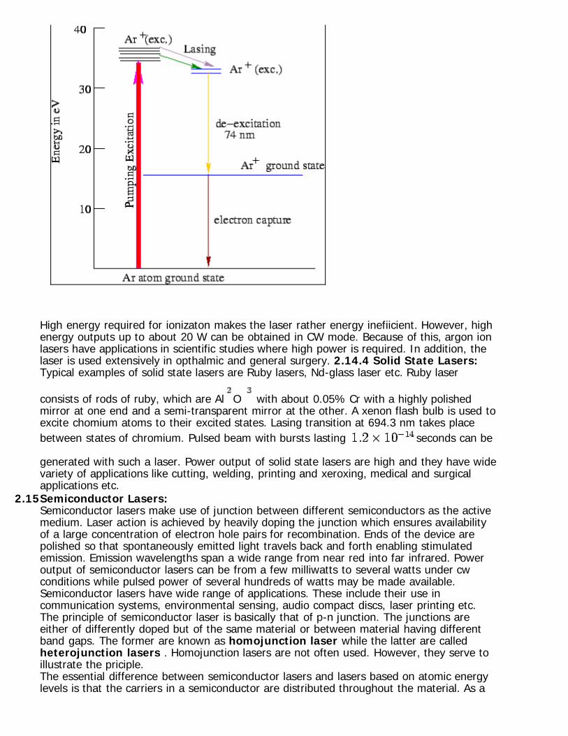
High energy required for ionizaton makes the laser rather energy inefiicient. However, highenergy outputs up to about 20 W can be obtained in CW mode. Because of this, argon ionlasers have applications in scientific studies where high power is required. In addition, thelaser is used extensively in opthalmic and general surgery. 2.14.4 Solid State Lasers: Typical examples of solid state lasers are Ruby lasers, Nd-glass laser etc. Ruby laser
consists of rods of ruby, which are Al O with about 0.05% Cr with a highly polishedmirror at one end and a semi-transparent mirror at the other. A xenon flash bulb is used toexcite chomium atoms to their excited states. Lasing transition at 694.3 nm takes placebetween states of chromium. Pulsed beam with bursts lasting seconds can be
generated with such a laser. Power output of solid state lasers are high and they have widevariety of applications like cutting, welding, printing and xeroxing, medical and surgicalapplications etc.
2.15Semiconductor Lasers: Semiconductor lasers make use of junction between different semiconductors as the active
medium. Laser action is achieved by heavily doping the junction which ensures availabilityof a large concentration of electron hole pairs for recombination. Ends of the device arepolished so that spontaneously emitted light travels back and forth enabling stimulatedemission. Emission wavelengths span a wide range from near red into far infrared. Poweroutput of semiconductor lasers can be from a few milliwatts to several watts under cwconditions while pulsed power of several hundreds of watts may be made available.Semiconductor lasers have wide range of applications. These include their use incommunication systems, environmental sensing, audio compact discs, laser printing etc.The principle of semiconductor laser is basically that of p-n junction. The junctions areeither of differently doped but of the same material or between material having differentband gaps. The former are known as homojunction laser while the latter are calledheterojunction lasers . Homojunction lasers are not often used. However, they serve toillustrate the priciple.
The essential difference between semiconductor lasers and lasers based on atomic energylevels is that the carriers in a semiconductor are distributed throughout the material. As a

result, while in case of a collection of atoms, the system interacts only with a probe beamwhose frequency is equal to the energy difference between atomic levels, a semiconductorwould interact with a probe (photon) as long as the energy of the photon is greater thanthe band gap. If is the incodent frequency and is the band gap, the absorptioncoefficient is proportional to the density of states at the energy , i.e., to
. The intensity of the probe beam diminishes, following Beer's law (
).
Suppose we use an optical pump to promote electrons from the valence band to theconduction band so that there is an appreciable population of electrons in the conductionband and holes in the valence band, up to the levels marked and in the
diagram. If we send a probe signal of frequency such that through
the material, the probe would see a population inversion in the sense that there aremore electrons in the upper level than in the lower level resulting in a gain.
2.15.1Homojunction Laser (Laser Diode):
Homojunction lasers are made of p-n junctions of either the same material or of materialhaving similar bandwidth. Population inversion can be achieved by heavily doping a p-type material with electrons or n-type material with holes.
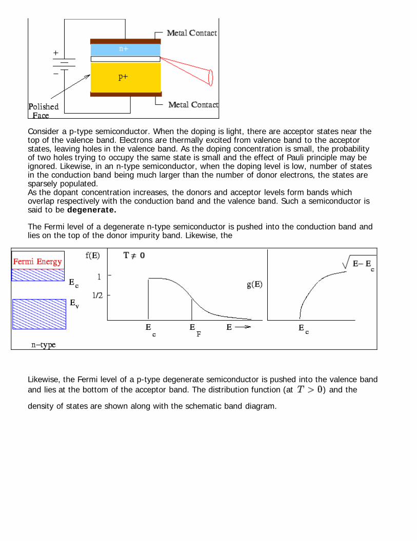
Consider a p-type semiconductor. When the doping is light, there are acceptor states near thetop of the valence band. Electrons are thermally excited from valence band to the acceptorstates, leaving holes in the valence band. As the doping concentration is small, the probabilityof two holes trying to occupy the same state is small and the effect of Pauli principle may beignored. Likewise, in an n-type semiconductor, when the doping level is low, number of statesin the conduction band being much larger than the number of donor electrons, the states aresparsely populated. As the dopant concentration increases, the donors and acceptor levels form bands whichoverlap respectively with the conduction band and the valence band. Such a semiconductor issaid to be degenerate.
The Fermi level of a degenerate n-type semiconductor is pushed into the conduction band andlies on the top of the donor impurity band. Likewise, the
Likewise, the Fermi level of a p-type degenerate semiconductor is pushed into the valence bandand lies at the bottom of the acceptor band. The distribution function (at ) and the
density of states are shown along with the schematic band diagram.

Consider a p-type degenerate semiconductor. is the probability that a state of energy
is occupied by an electron. It follows that is the probability that a state of energy
is occupied by a hole. Recalling that
if , the denominator is large. is, therefore, small. Thus, if the Fermilevel is
inside the valence band, for , the probability of holes can be large. Likewise, for an
type degenerate semiconductor, the probability of occupation of electrons in the conductionband can be large.
i p-n Junction of Degenerate Semiconductor : Consider a p-n junction of degeneratesemiconductors with a heavily doped n-type on one side and a heavily doped p-type on theother. In the absence of an applied voltage, the Fermi level is the same throughout, i.e,
. The Fermi level lies inside the valence band of the p-side and inside
the conduction band of the n-side. A contact potential is built across the
junction which prevents electrons on the n-side to diffuse into the conduction band on thep-side. Similarly, the holes on the p-side of the junction face a barrier to diffuse to the n-side.

When a forward bias is applied (i.e., p-side positive and n-side negative) is lowered
and is raised, the separation . The barrier potential is reduced and
electrons from the degenerate n-side diffuse to the p-region through the depletion layer.Similarly, the holes from the p-side move towards n-side.
As a result the junction is no longer depleted. Near the junction an incoming signal sees apopulation inversion with more electrons at a higher level. If the signal frequency is largerthan the frequency corresponding to the band gap, there will be gain for frequencies smallerthan and absorption for larger frequencies.

Gain is proportional to the carrier population above the threshold value. Since diodecurrent is proportional to the carrier density, one can define a threshold current
above which lasing occurs. The problem of homojunction laser is that the threshold current density is rather large (
A/mm ) which would require a good heat sink for continuous removal ofgenerated heat. Homojunction lasers are, therefore, used in "pulsed mode" or attemperature below 100 K. Another disadvantage of homojunction laser is that the junction region is wide whichresults in a divergent beam.
2.15.2Heterojunction Laser:
We have seen that homojunction lasers suffer from two disadvantages.
Wide beam widthLarge threshold current requiring low operating temperatures.
Reduction of threshold current may be achieved by confining carriers to a small regionaround the junction.

A heterojunction consists of two single crystal semiconductors with different bandgapenergies. Because of different refractive index on either side of the junction, the carriers areconfined in the junction layer and recombine. The choice of material for junction is decidedby lattice matching. GaAs with a lattice constant of 5.65 Å has nearly the same latticeconstant as AlAs which has a lattice constant of 5.66 Å. Thus in Al Ga As, the Al atoms
occupy Ga sites.
In the single heterojunction shown above, the difference between the refractive indices ofn-type and p-type GaAs is small. A double heterojunction is generally preferred as it leadsto better confinement.
In the schematic double heterojunction shown here the intermediate GaAs layer has higherbandwidth material Al Ga As on either side. This results in the carriers getting
confined to the central layer as the electrons which diffuse to the junction from the n-sidefind a barrier which stops them from diffusing to the left. Similarly, the holes are preventedfrom diffusing to the right.
The figure below shows a schematic figure of a double heterojunction laser with stripe

geometry. In this geometry the top electrode does not cover the top surface of thestructure. Instead, the top is covered with an insulating layer of silicon dioxide and thecontact of the electrode is made over a narrow channel roughly 10 microns wide.
2.15.3Buried Heterostructure Laser :
Laser confinement can be further improved by index guided mechanism in which theoptical power is confined by a lateral variation of the refractive index. The principle is thesame as for obtaining vertical confinement in DH laser in that a higher band gap material(AlGaAs) is etched both latewrally and vertically. As the active layer is surrounded by amaterial of lower refractive index, it provides a waveguide. The threshold current is

reduced to less than 10 mA because of further reduction in stripe width.
2.16 Properties of GaAs Laser:
Modes in Laser Cavity: The stripe geometry essentially implies that the active region is a rectangular cavity oflength , width and height . This results in only certain modes being excited.
The resonance condition is given by the dimension of the cavity along any of the threedirections being equal to multiple of half wavelength. For a longitudinal mode, the conditionis given by
where is the wavelength in the medium and is an integer. In terms of the free space
wavelength and refractive index , the condition is

Similar conditions apply in the other two directions.
Each mode is, therefore, described by a set of three integers . When and are
sufficiently small, only the lowest transverse mode (TEM ) is excited.
Example:
A heterostructure diode has a cavity length of 500 microns. The peak wavelength ofradiation is at 870 nm and the refractive index is 4. Find the index of the longitudinal modeand the separation .
Solution: Using , we get . is given by the wavelength separation
between two consecutive modes
Substituting values, nm.
The number of modes excited depends on the FWHM above the gain threshold. An indexguided structure has a shorter cavity length which increases the spacing between adjacentmode frequencies so that fewer modes can be supported within the envelope of the opticalgain.
Example: The gain envelope of a DH structure has FWHM of 5 nm wavelength. Use the data of theprevious example to compute the number of longitudinal modes that may be excited in thecavity. Solution: From the previous example, we have, nm. As FWHM is 5 nm, the number ofmodes is . The following exercise shows that the number of modes is reduced
if the cavity length is decreased.
Exercise: Determine the number of longitudinal modes excited if the cavity length in the aboveexample is reduced to 200 microns.(Ans. 11) When the diode current increases, the optical power also increases. Above the thresholdregion, the spectrum becomes sharper with the increase in optical power and fewer modesare excited. GaAs laser does not have as good directionality and monochromaticity

properties as for a gas laser. However, they have certain advantages which make themattractive :
2.17Vertical Surface Emitting Laser :
Vertical Surface Emitting Laser (VCSEL, pronounced Vixel ) is a semiconductor devicewhich emits beam of a small circular cross section perpendicular to the substrate.
The device consists of a vertical sandwitch of a p-type multilayer, an active region and ann-type multilayer. The two multilayers provide mirrors for resonant cavity and are calleddistributed Bragg reflectors. Wavelength tuning is possible by a proper choice ofsemiconductors and dopants while fabricating the multilayers. The features of VCSEL are asfollows:
System has high gain and low turn on voltage. By high speed turning on and off itcan be modulated to a speed greater than 10 Gbps.As the output beam has circular cross section, it is easy to couple to a fiber.The beam has low divergence.

Emission takes place from surface rather than from the edge.A thinner active region leads to a lower threshold current.
2.18Noise in a Laser Source :
The process of optical communication has three essential components, viz., the source, themedium of propagation (fiber) and the detection mechanism. Each one of these contributeto corruption of the signal because of noise associated with it. The operating characteristics of laser diodes cause three types of noise, which, in turn, willaffect the receiver output. The primary noise sources for the transmitter are :
Modal or speckle noise.Mode-partition noise.reflection noise.
Speckle Noise :
When light from a coherent laser source is launched into a multimode fiber, several modesare simultaneously excited in the fiber. As long as these modes maintain their relativephase coherence, the radiation pattern in any plane is due to interference between suchmodes. The interference pattern takes the shape of speckle , as shown in the figure.
The number of speckles is approximately equal to the number of modes propagating. Laser
speckles appear whenever an optically rough surface is illuminated by a highly coherentlight provided the roughness of the surface is at least of the order of wavelength of lightused.

The optical disturbance at any point along the path consists of wavelets arising from adifferent element of the surface. Because of different sizes of surface granularities, suchwavelets have different phases. Speckles look like noise, but in reality, they are not.According to Gabor, winner of Nobel prize for invention of holography, ``it is not reallynoise, it is information that we do not want." In this case, the unwanted information is thegranularity of the surface. Speckle is not without its use. A new branch of opticalmeasurement technique, known as speckle metrology uses speckle pattern in non-destructive testing of a surface.
Speckle noise, therefore, is not speckle itself but a variation in the speckle pattern due totemporal variation of the coherent optical signal. A second cause of such noise is presenceof elements which make propagation mode-selective. Such time varying speckle patternfalling on a photodetector produces a time varying noise in the received signal,which degrades its performance.
The way to eliminate modal noise is to use single mode fibers for coupling to laser sourcesand to use LEDs for multimode fibers (which do not produce speckles).
Mode-Partition Noise :
Mode partition noise is due to intensity fluctuations in the longitudinal modes of a laserdiode. We have seen that the cavity modes in a laser (not to be confused with fiber modes)are defined by a unique wavelength given by
where is the refractive index of the medium and isthe length of the laser cavity. Output from a laser diode could be from more than onelongitudinal mode. The total power output coupled to the fiber is constant in time but thedistribution of power among various cavity modes changes with time. This fluctuation inpower at various times is called the mode partition noise. This is the primary source of noisein a single mode fiber.
Reflection Noise :
Light coupled to a fiber may be reflected back from various surfaces, like fiber junctions,and re-enter the laser cavity. Such reflected light can couple with the cavity modes andchange their phase. Reflection noise can be eliminated by using index-matching fluids at thejoints.
Spontaneous Emission Noise :
In addition to above, a laser source has noise due to spontaneous emission of radiationbetween the lasing levels. Unlike stimulated emission, such emissions are not coherent.Spontaneous emissions cause a spectral width to the laser output and also reduces SNR atthe output of laser amplifiers.

References :
1. S.O. Kasap, Optoelectronics and Photonics, Prentice Hall, N.J. (2001)
2. A. Yariv, Introduction to Optical Electronics, Holt, Rinehart and Winston, Inc. (1991)
3. K. A. Jones, Introduction to Optical Electronics, Harper & Row (1987)
4. C. R. Pollock, Fundamentals of Optoelectronics, Irwin (1995)
5. J. Wilson and J. F. B. Hawkers, Optoelectronics - An Introduction, Prentice Hall (1993)
6. J. T. Verdeyen, Laser Electronics, Prentice Hall (1989)
7. W. T. Silvast, Laser Fundamentals, Cambridge (2004)
Recap In this lecture you have learnt the following
Types of Lasers and Applications
Helium-Neon Laser
Carbon dioxide Laser
Argon-ion Laser
Semiconductor Lasers
Homojunction Laser (Laser Diode)
Heterojunction Laser
Properties of GaAs Laser
Vertical Surface Emitting Laser
Noise in a Laser Source