Embed Size (px)
Citation preview
Logic synthesis
Module: Electronics, 3rd year
Digital Systems Design withHardware Description Languages
1Rajda & Kasperek © 2019 Dept. of Electronics, AGH UST
Agenda
• Introduction to the synthesis
• Synthesis of the basic elements
• Hardware representationof VHDL objects
• Synthesis of complex circuits
• Synthesis of types
• Non-synthesizable structures
2Rajda & Kasperek © 2019 Dept. of Electronics, AGH UST
Logic Syntesis
Literature
• „A VHDL Synthesis primer” J.Bhasker,
• „VHDL A Logic Synthesis Approach” D.Naylor, S.Jones,
• „VHDL Coding and Logic Synthesis with SYNOPSIS”W.F.Lee,
• „Reuse Methodology Manual” M.Keating, P.Bricaud,
• „Synthesis and Simulation Design Guide” (Xilinx manual)
• „Xilinx Synthesis Technology (XST) User Guide”(Xilinx manual)
• „Digital System Design with VHDL”M.Zwoliński(translated: „Projektowanie układów cyfrowych
z wykorzystaniem języka VHDL”)
3Rajda & Kasperek © 2019 Dept. of Electronics, AGH UST
Synthesis & implementation
Xilinx CPLD/FPGA Design
4Rajda & Kasperek © 2019 Dept. of Electronics, AGH UST
Synthesis & implementation
Design in Active-HDL environment
5Rajda & Kasperek © 2019 Dept. of Electronics, AGH UST
Synthesis & implementation
Design in Active-HDL environment: Design Flow
External toolsfor synthesisand implementation
Graphical shell by selecting option:
Tools/Preferences/Environment/Flows/Integrated Tools
and
View/Flow
6Rajda & Kasperek © 2019 Dept. of Electronics, AGH UST
Synthesis of the basic elements
Arithmetic and logical operators
architecture behavioral of AND_gate isbegin
process (A, B) -- synthesized AND gatebegin
if A = ‘1’ and B = ‘1’ thenX <= ‘1’ ;
elseX <= ‘0’ ;
end if ;end behavioral;
architecture inferred of AND_gate isbegin -- inferred AND gate
X <= A and B; -- from the library of end inferred; -- presynthesized elements
Inferred and or xor not nor nand xnoroperators : + - * / = /= > >= < <= ...
7Rajda & Kasperek © 2019 Dept. of Electronics, AGH UST
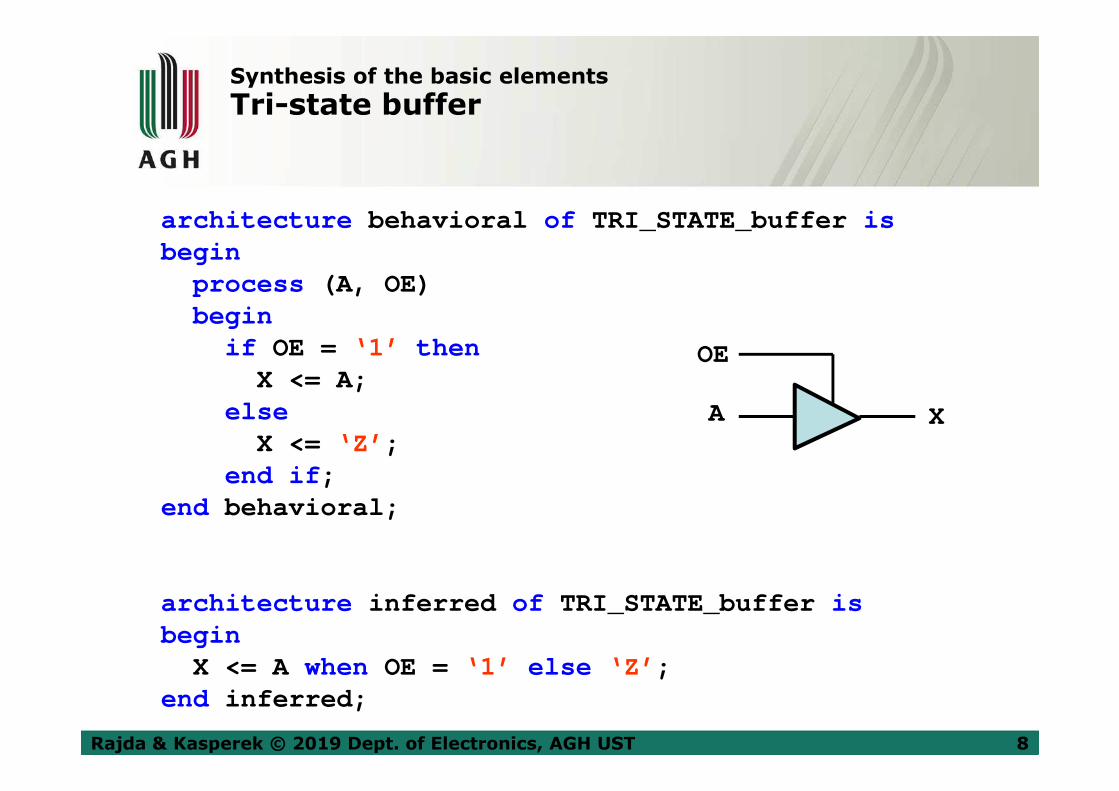
Synthesis of the basic elements
Tri-state buffer
architecture behavioral of TRI_STATE_buffer isbegin
process (A, OE)begin
if OE = ‘1’ thenX <= A;
elseX <= ‘Z’ ;
end if ;end behavioral;
architecture inferred of TRI_STATE_buffer isbegin
X <= A when OE = ‘1’ else ‘Z’ ; end inferred;
OE
XA
8Rajda & Kasperek © 2019 Dept. of Electronics, AGH UST
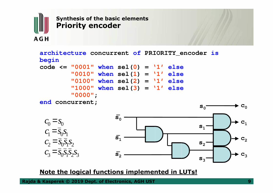
Synthesis of the basic elements
Priority encoder
architecture concurrent of PRIORITY_encoder isbegincode <= "0001" when sel( 0) = ‘1’ else
"0010" when sel( 1) = ‘1’ else"0100" when sel( 2) = ‘1’ else"1000" when sel( 3) = ‘1’ else"0000" ;
end concurrent;
Note the logical functions implemented in LUTs!
32103 ssssc =2102 sssc =
101 ssc =00 sc = s0
s1
s2
s0
s1
s3
s2
c0
c1
c3
c2
9Rajda & Kasperek © 2019 Dept. of Electronics, AGH UST
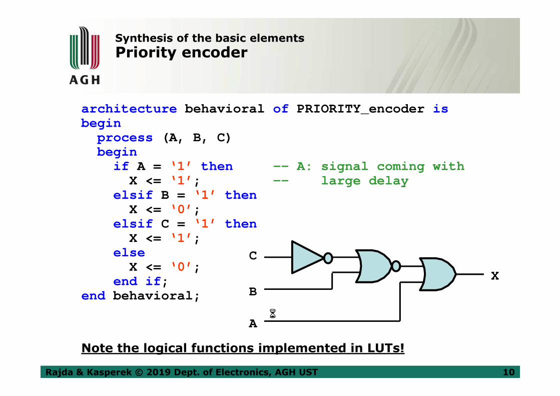
Synthesis of the basic elements
Priority encoder
architecture behavioral of PRIORITY_encoder isbegin
process (A, B, C)begin
if A = ‘1’ then -- A: signal coming withX <= ‘1’ ; -- large delay
elsif B = ‘1’ thenX <= ‘0’ ;
elsif C = ‘1’ thenX <= ‘1’ ;
else X <= ‘0’ ;
end if ;end behavioral;
A
BX
C
�
Note the logical functions implemented in LUTs!
10Rajda & Kasperek © 2019 Dept. of Electronics, AGH UST
Logic synthesis
Hardware representation of VHDL objects
An object - signal or variable - may be represented as:
• flip-flop(edge-triggered memory element)
• latch(level-triggered memory element)
• wire(combinatorial element)
11Rajda & Kasperek © 2019 Dept. of Electronics, AGH UST
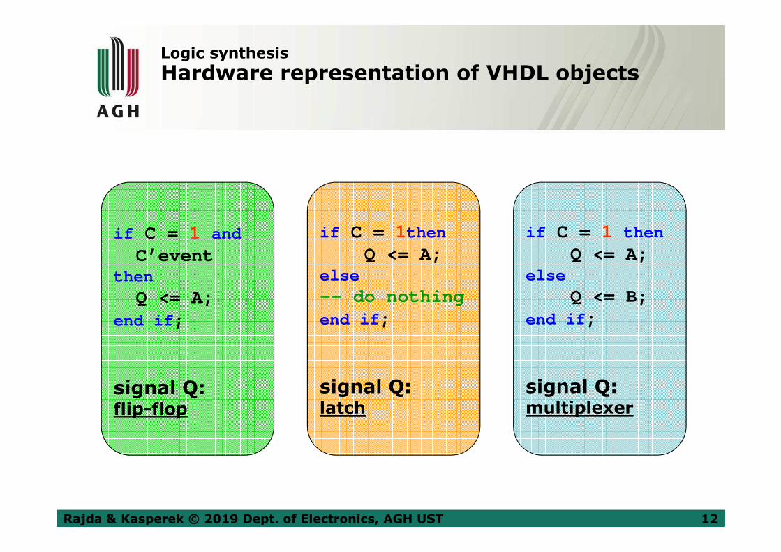
Logic synthesis
Hardware representation of VHDL objects
if C = 1 and
C’eventthen
Q <= A;end if ;
signal Q: flip-flop
if C = 1then
Q <= A;else-- do nothingend if ;
signal Q:latch
if C = 1 then
Q <= A;else
Q <= B;end if ;
signal Q: multiplexer
12Rajda & Kasperek © 2019 Dept. of Electronics, AGH UST
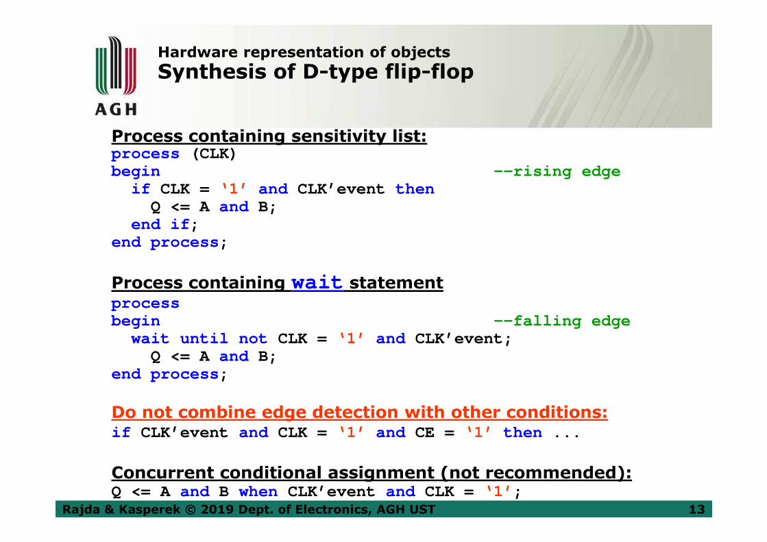
Hardware representation of objects
Synthesis of D-type flip-flop
Process containing sensitivity list:process (CLK)begin --rising edge
if CLK = ‘1’ and CLK’event thenQ <= A and B;
end if ;end process ;
Process containing wait statementprocessbegin --falling edge
wait until not CLK = ‘1’ and CLK’event; Q <= A and B;
end process ;
Do not combine edge detection with other conditions:if CLK’event and CLK = ‘1’ and CE = ‘1’ then ...
Concurrent conditional assignment (not recommended):Q <= A and B when CLK’event and CLK = ‘1’ ;
13Rajda & Kasperek © 2019 Dept. of Electronics, AGH UST
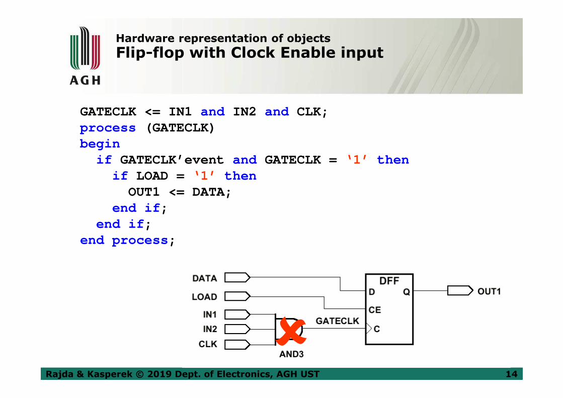
Hardware representation of objects
Flip-flop with Clock Enable input
GATECLK <= IN1 and IN2 and CLK;process (GATECLK)begin
if GATECLK’event and GATECLK = ‘1’ thenif LOAD = ‘1’ then
OUT1 <= DATA;end if ;
end if ;end process ;
�14Rajda & Kasperek © 2019 Dept. of Electronics, AGH UST
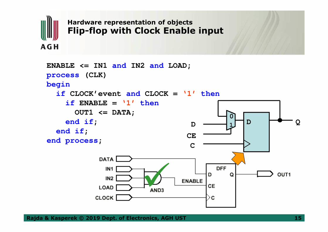
Hardware representation of objects
Flip-flop with Clock Enable input
ENABLE <= IN1 and IN2 and LOAD;process (CLK)begin
if CLOCK’event and CLOCK = ‘1’ thenif ENABLE = ‘1’ then
OUT1 <= DATA;end if ;
end if ;end process ;
D
CEC
QD01
�15Rajda & Kasperek © 2019 Dept. of Electronics, AGH UST
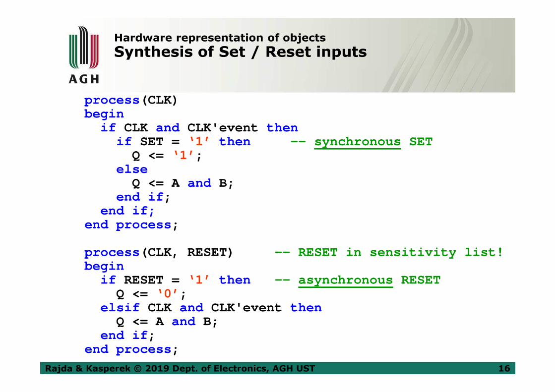
Hardware representation of objects
Synthesis of Set / Reset inputs
process (CLK) begin
if CLK and CLK'event thenif SET = ‘1’ then -- synchronous SET
Q <= ‘1’ ; else
Q <= A and B;end if ;
end if;end process ;
process (CLK, RESET) -- RESET in sensitivity list!begin
if RESET = ‘1’ then -- asynchronous RESETQ <= ‘0’ ;
elsif CLK and CLK'event thenQ <= A and B;
end if ;end process ;
16Rajda & Kasperek © 2019 Dept. of Electronics, AGH UST
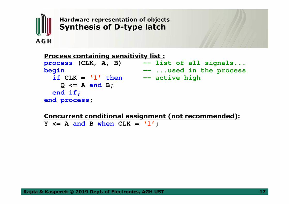
Hardware representation of objects
Synthesis of D-type latch
Process containing sensitivity list :process (CLK, A, B) -- list of all signals...begin -- ... used in the process
if CLK = ‘1’ then -- active highQ <= A and B;
end if;end process ;
Concurrent conditional assignment (not recommended): Y <= A and B when CLK = ‘1’ ;
17Rajda & Kasperek © 2019 Dept. of Electronics, AGH UST
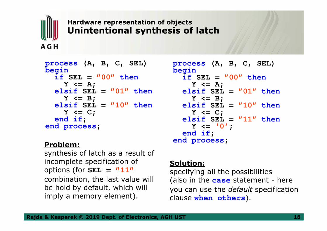
Hardware representation of objects
Unintentional synthesis of latch
process (A, B, C, SEL)begin
if SEL = ”00” thenY <= A;
elsif SEL = ”01” thenY <= B;
elsif SEL = ”10” thenY <= C;
end if ;end process ;
process (A, B, C, SEL)begin
if SEL = ”00” thenY <= A;
elsif SEL = ”01” thenY <= B;
elsif SEL = ”10” thenY <= C;
elsif SEL = ”11” thenY <= ‘0’ ;
end if ;end process ;
Solution:specifying all the possibilities(also in the case statement - here
you can use the default specification clause when others ).
Problem:synthesis of latch as a result of incomplete specification of options (for SEL = ”11”combination, the last value will be hold by default, which will imply a memory element).
18Rajda & Kasperek © 2019 Dept. of Electronics, AGH UST
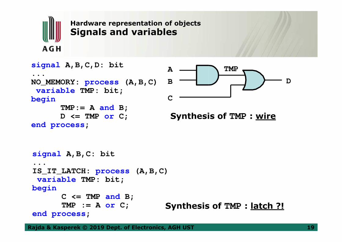
Hardware representation of objects
Signals and variables
signal A,B,C,D: bit...NO_MEMORY:process (A,B,C)
variable TMP: bit;begin
TMP:= A and B;D <= TMP or C;
end process ;
signal A,B,C: bit...IS_IT_LATCH: process (A,B,C)
variable TMP: bit;begin
C <= TMP and B;TMP := A or C;
end process ;
A
B D
C
TMP
Synthesis of TMP: wire
Synthesis of TMP: latch ?!
19Rajda & Kasperek © 2019 Dept. of Electronics, AGH UST
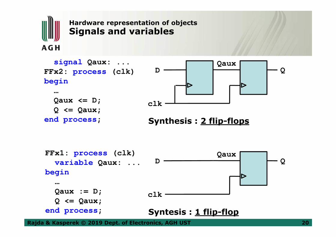
Hardware representation of objects
Signals and variables
signal Qaux: ...FFx2: process (clk)begin
…Qaux <= D;Q <= Qaux;
end process ;
FFx1: process (clk)variable Qaux: ...
begin…Qaux := D;Q <= Qaux;
end process ; Syntesis : 1 flip-flop
D
clk
QauxQ
Synthesis : 2 flip-flops
D
clk
QauxQ
20Rajda & Kasperek © 2019 Dept. of Electronics, AGH UST
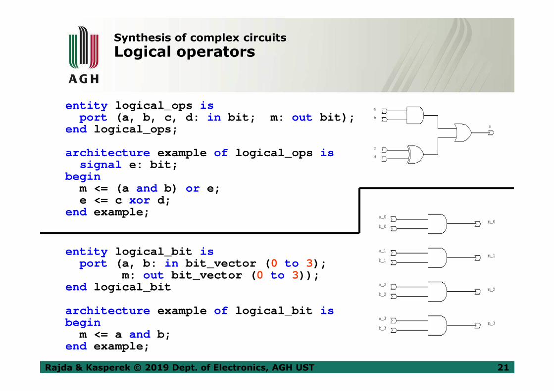
Synthesis of complex circuits
Logical operators
entity logical_ops isport (a, b, c, d: in bit; m: out bit);
end logical_ops;
architecture example of logical_ops issignal e: bit;
beginm <= (a and b) or e; e <= c xor d;
end example;
entity logical_bit isport (a, b: in bit_vector ( 0 to 3);
m: out bit_vector ( 0 to 3));end logical_bit
architecture example of logical_bit isbegin
m <= a and b;end example;
21Rajda & Kasperek © 2019 Dept. of Electronics, AGH UST
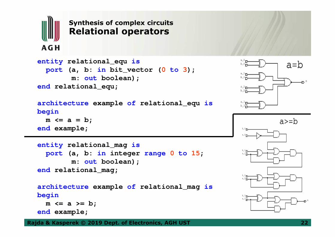
Synthesis of complex circuits
Relational operators
entity relational_equ isport (a, b: in bit_vector ( 0 to 3);
m: out boolean);end relational_equ;
architecture example of relational_equ isbegin
m <= a = b;end example;
entity relational_mag isport (a, b: in integer range 0 to 15;
m: out boolean);end relational_mag;
architecture example of relational_mag isbegin
m <= a >= b; end example;
22Rajda & Kasperek © 2019 Dept. of Electronics, AGH UST
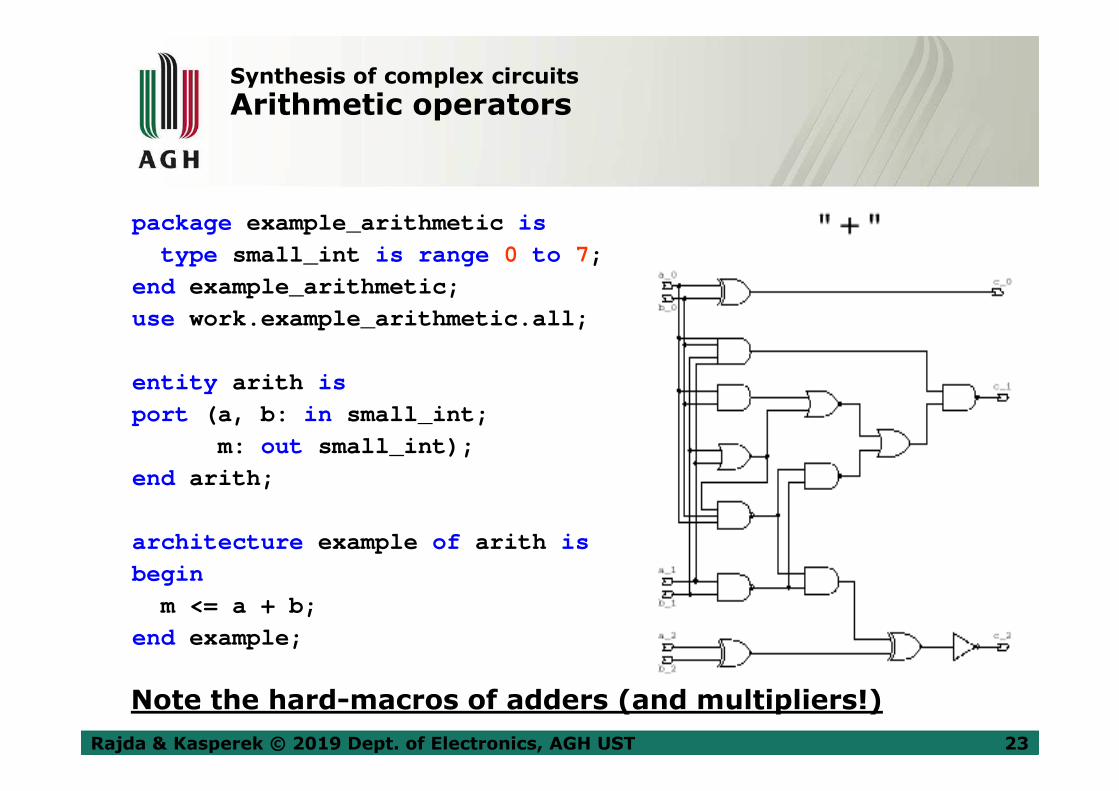
Synthesis of complex circuits
Arithmetic operators
package example_arithmetic is
type small_int is range 0 to 7;
end example_arithmetic;
use work.example_arithmetic.all;
entity arith is
port (a, b: in small_int;
m: out small_int);
end arith;
architecture example of arith is
begin
m <= a + b;
end example;
Note the hard-macros of adders (and multipliers!)
23Rajda & Kasperek © 2019 Dept. of Electronics, AGH UST

Synthesis of complex circuits
Selection statements
Sequential selection statements• conditional signal assignment: if ...• selected signal assignment: case ...
Concurrent selection statements• conditional signal assignment: when...• selected signal assignment: with ...
24Rajda & Kasperek © 2019 Dept. of Electronics, AGH UST
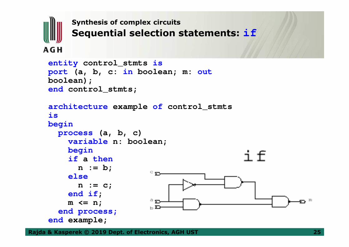
Synthesis of complex circuits
Sequential selection statements: if
entity control_stmts isport (a, b, c: in boolean; m: out boolean);end control_stmts;
architecture example of control_stmts isbegin
process (a, b, c)variable n: boolean;beginif a then
n := b;else
n := c;end if ;m <= n;
end process;end example;
25Rajda & Kasperek © 2019 Dept. of Electronics, AGH UST
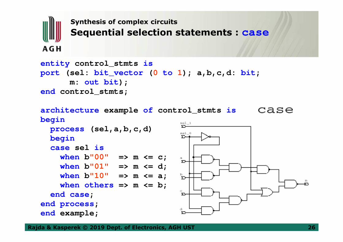
Synthesis of complex circuits
Sequential selection statements : case
entity control_stmts isport (sel: bit_vector ( 0 to 1); a,b,c,d: bit ;
m: out bit );end control_stmts;
architecture example of control_stmts isbegin
process (sel,a,b,c,d)begincase sel is
when b"00" => m <= c;when b"01" => m <= d;when b"10" => m <= a;when others => m <= b;
end case ;end process ;end example;
26Rajda & Kasperek © 2019 Dept. of Electronics, AGH UST
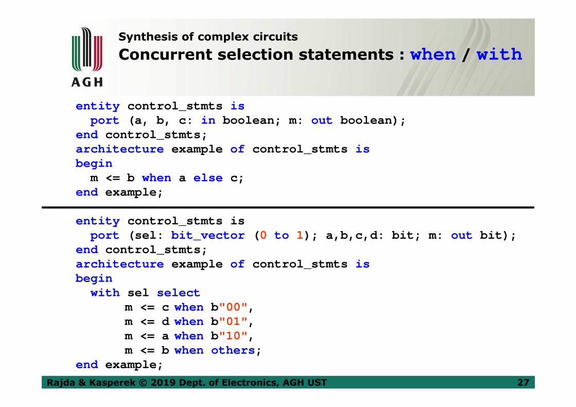
Synthesis of complex circuits
Concurrent selection statements : when / with
entity control_stmts isport (a, b, c: in boolean; m: out boolean);
end control_stmts;architecture example of control_stmts isbegin
m <= b when a else c;end example;
entity control_stmts isport (sel: bit_vector ( 0 to 1); a,b,c,d: bit; m: out bit);
end control_stmts;architecture example of control_stmts isbegin
with sel selectm <= c when b"00" ,m <= d when b"01" ,m <= a when b"10" ,m <= b when others ;
end example;
27Rajda & Kasperek © 2019 Dept. of Electronics, AGH UST
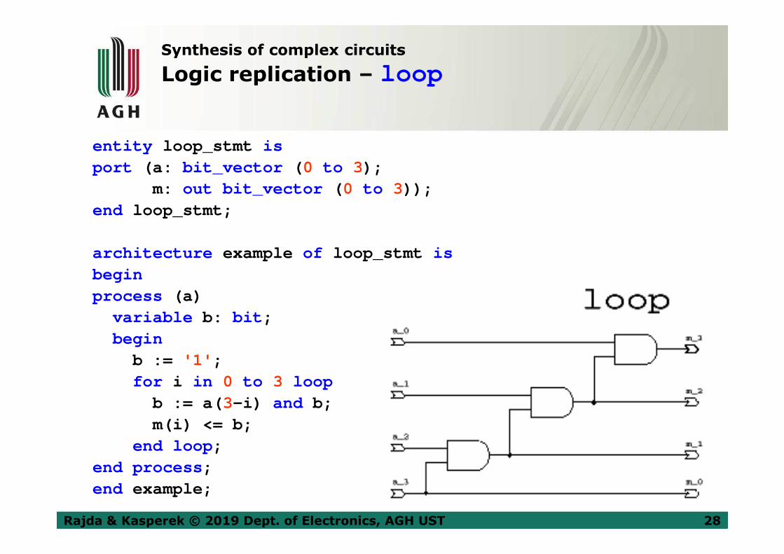
Synthesis of complex circuits
Logic replication – loop
entity loop_stmt isport (a: bit_vector ( 0 to 3);
m: out bit_vector ( 0 to 3));end loop_stmt;
architecture example of loop_stmt isbeginprocess (a)
variable b: bit ;begin
b := '1' ;for i in 0 to 3 loop
b := a( 3-i) and b;m(i) <= b;
end loop ;end process ;end example;
28Rajda & Kasperek © 2019 Dept. of Electronics, AGH UST
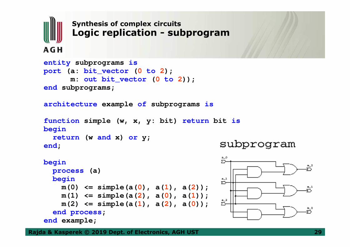
Synthesis of complex circuits
Logic replication - subprogram
entity subprograms isport (a: bit_vector ( 0 to 2);
m: out bit_vector ( 0 to 2));end subprograms;
architecture example of subprograms is
function simple (w, x, y: bit) return bit isbegin
return (w and x) or y;end ;
beginprocess (a)begin
m(0) <= simple(a( 0), a( 1), a( 2));m(1) <= simple(a( 2), a( 0), a( 1));m(2) <= simple(a( 1), a( 2), a( 0));
end process ;end example;
29Rajda & Kasperek © 2019 Dept. of Electronics, AGH UST
Synthesis of complex circuits
Shifters
Sequential (shift register):• with concatenation operator (&)
shreg <= shreg ( 6 downto 0) & SI;• with loop statemnet for ... loop
for i in 0 to 6 loopshreg(i+ 1) <= shreg(i);
end loop ;shreg( 0) <= SI;
• with shift operators (sll , srl , ... )
Combinatorial (barrel shifter):• with shift operators (sll , srl , ... )
with SEL selectSO <= DI when "00" ,
DI sll 1 when "01" ,DI sll 2 when "10" ,DI sll 3 when others ;
• with concatenation operator (&)
30Rajda & Kasperek © 2019 Dept. of Electronics, AGH UST
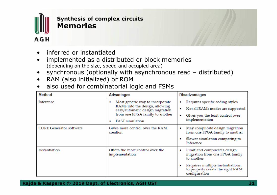
Synthesis of complex circuits
Memories
• inferred or instantiated• implemented as a distributed or block memories
(depending on the size, speed and occupied area)
• synchronous (optionally with asynchronous read – distributed)• RAM (also initialized) or ROM• also used for combinatorial logic and FSMs
31Rajda & Kasperek © 2019 Dept. of Electronics, AGH UST
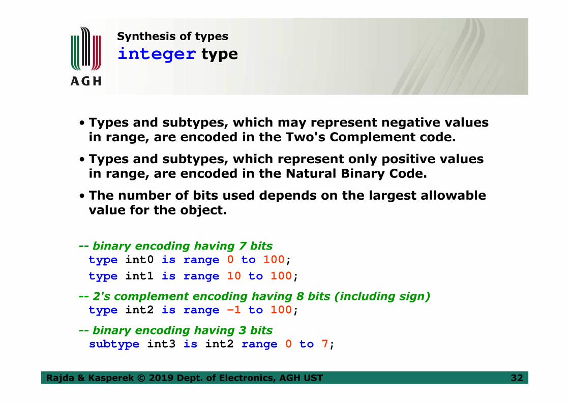
Synthesis of types
integer type
• Types and subtypes, which may represent negative values in range, are encoded in the Two's Complement code.
• Types and subtypes, which represent only positive values in range, are encoded in the Natural Binary Code.
• The number of bits used depends on the largest allowable value for the object.
-- binary encoding having 7 bits
type int0 is range 0 to 100 ;
type int1 is range 10 to 100 ;
-- 2's complement encoding having 8 bits (including sign)
type int2 is range -1 to 100 ;
-- binary encoding having 3 bits
subtype int3 is int2 range 0 to 7;
32Rajda & Kasperek © 2019 Dept. of Electronics, AGH UST
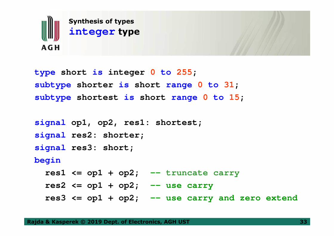
Synthesis of types
integer type
type short is integer 0 to 255 ;
subtype shorter is short range 0 to 31;
subtype shortest is short range 0 to 15;
signal op1, op2, res1: shortest;
signal res2: shorter;
signal res3: short;
begin
res1 <= op1 + op2; -- truncate carry
res2 <= op1 + op2; -- use carry
res3 <= op1 + op2; -- use carry and zero extend
33Rajda & Kasperek © 2019 Dept. of Electronics, AGH UST
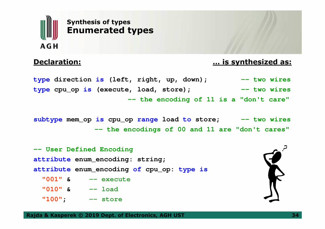
Synthesis of types
Enumerated types
Declaration: … is synthesized as:
type direction is (left, right, up, down); -- two wires
type cpu_op is (execute, load, store); -- two wires
-- the encoding of 11 is a "don't care"
subtype mem_op is cpu_op range load to store; -- two wires
-- the encodings of 00 and 11 are "don't cares"
-- User Defined Encoding
attribute enum_encoding: string;
attribute enum_encoding of cpu_op: type is
"001" & -- execute
"010" & -- load
"100" ; -- store
34Rajda & Kasperek © 2019 Dept. of Electronics, AGH UST
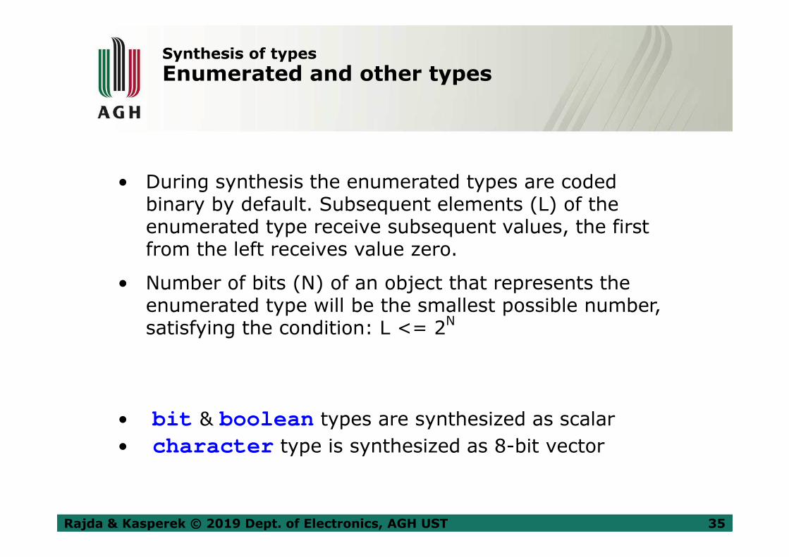
Synthesis of types
Enumerated and other types
• During synthesis the enumerated types are coded binary by default. Subsequent elements (L) of the enumerated type receive subsequent values, the first from the left receives value zero.
• Number of bits (N) of an object that represents the enumerated type will be the smallest possible number, satisfying the condition: L <= 2
N
• bit & boolean types are synthesized as scalar
• character type is synthesized as 8-bit vector
35Rajda & Kasperek © 2019 Dept. of Electronics, AGH UST
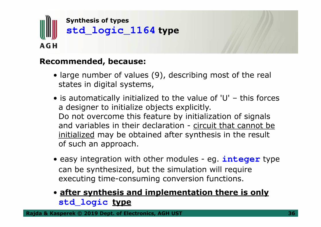
Synthesis of types
std_logic_1164 type
Recommended, because:
• large number of values (9), describing most of the realstates in digital systems,
• is automatically initialized to the value of 'U' – this forcesa designer to initialize objects explicitly.Do not overcome this feature by initialization of signals and variables in their declaration - circuit that cannot be initialized may be obtained after synthesis in the resultof such an approach.
• easy integration with other modules - eg. integer type
can be synthesized, but the simulation will requireexecuting time-consuming conversion functions.
• after synthesis and implementation there is only
std_logic type
36Rajda & Kasperek © 2019 Dept. of Electronics, AGH UST
Synthesis of FSMs
FSM states encoding algorithms
• Autoselects the needed optimization algorithms during the synthesis process
• One-Hotensures that an individual state register is dedicated to one state. Only one flip-flopis active (hot) at any time. Very appropriate with most FPGAs where a large numberof flip-flops are available. Also a good alternative to optimize speed or to reduce power.
• Compactminimizes the number of state variables and flip-flops. Appropriate when optimizing area.
• Sequentialconsists of identifying long paths and applying successive radix two codesto the states on these paths. Next state equations are minimized
• Grayguarantees that only one state variable switches between two consecutive states. Appropriate for controllers exhibiting long paths without branching
• Johnsonmuch like Gray option. Shows benefits with FSM containing long paths with no branching.
• Usercauses the synthesis tool to use the encoding defined in the source file
• Speed1oriented for speed optimization. The number of bits for a state register depends on the particular FSM, but generally it is greater than the number of FSM states.
37Rajda & Kasperek © 2019 Dept. of Electronics, AGH UST
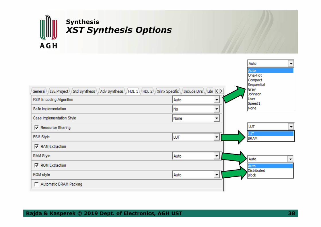
Synthesis
XST Synthesis Options
38Rajda & Kasperek © 2019 Dept. of Electronics, AGH UST
Synthesis
Non-synthesizable structures
• timing clauses:
- assignments (after , transport , inertial )
- wait for
• floating-point data types (real )
• file operations – reduced:
- read : memory initialization from file
- write : debug
39Rajda & Kasperek © 2019 Dept. of Electronics, AGH UST
To be continued…
40Rajda & Kasperek © 2019 Dept. of Electronics, AGH UST