Embed Size (px)
Citation preview
7/23/2019 MODULE TAXATION 1
http://slidepdf.com/reader/full/module-taxation-1 1/2
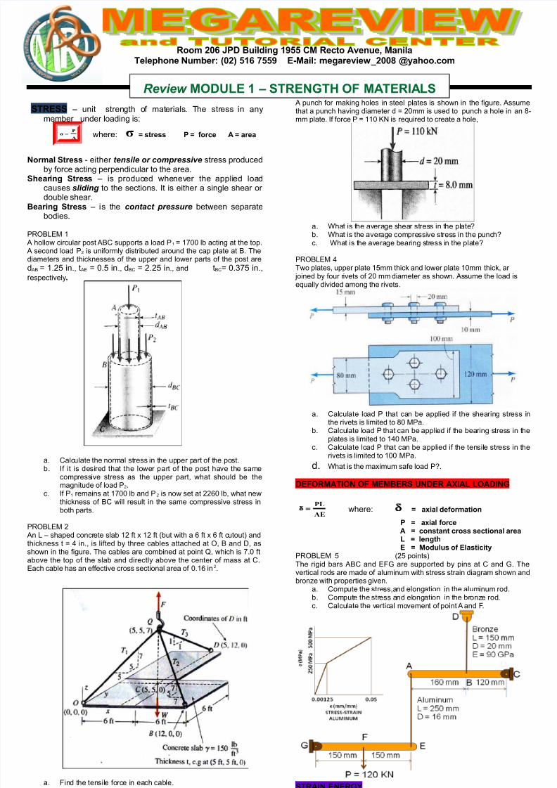
Room 206 JPD Building 1955 CM Recto Avenue, ManilaTelepone !um"e#$ %02& 516 '559 ()Mail$ mega#evie*+200 -.aoo/com
TR( unit strength of materials. The stress in anymember under loading is:
A
Pσ =
where: σ 3t#e33 P 4o#ce A a#ea
!o#mal t#e33 - either tensile or compressive stress producedby force acting perpendicular to the area.
ea#ing t#e33 – is produced whenever the applied loadcauses sliding to the sections. It is either a single shear or double shear.
Bea#ing t#e33 – is the contact pressure between separatebodies.
PRO!"# $ % hollow circular post %& supports a load P$ ' $()) lb acting at the top. % second load P* is uniformly distributed around the cap plate at . Thediameters and thic+nesses of the upper and lower parts of the post are
d % ' $.*, in. t % ' )., in. d& ' *.*, in. and t&' ).(, in.
r espectively/
a. &alculate the normal stress in the upper part of the post.b. If it is desired that the lower part of the post have the same
compressive stress as the upper part what should be themagnitude of load P*.
c. If P$ remains at $()) lb and P* is now set at **/) lb what newthic+ness of & will result in the same compressive stress inboth parts.
PRO!"# * %n ! – shaped concrete slab $* ft 0 $* ft 1but with a / ft 0 / ft cutout2 andthic+ness t ' 3 in. is lifted by three cables attached at O and 4 as
shown in the figure. The cables are combined at point 5 which is (.) ftabove the top of the slab and directly above the center of mass at &."ach cable has an effective cross sectional area of ).$/ in*.
a. 6ind the tensile force in each cable.b. 6ind the average stress in each cable.
PRO!"#
% punch for ma+ing holes in steel plates is shown in the figure. %ssumethat a punch having diameter d ' *)mm is used to punch a hole in an 7-mm plate. If force P ' $$) 89 is reuired to create a hole
a. ;hat is the average shear stress in the plate<b. ;hat is the average compressive stress in the punch<c. ;hat is the average bearing stress in the plate<
PRO!"# 3Two plates upper plate $,mm thic+ and lower plate $)mm thic+ ar
=oined by four rivets of *) mm diameter as shown. %ssume the load iseually divided among the rivets.
a. &alculate load P that can be applied if the shearing stress inthe rivets is limited to 7) #Pa.
b. &alculate load P that can be applied if the bearing stress in theplates is limited to $3) #Pa.
c. &alculate load P that can be applied if the tensile stress in therivets is limited to $)) #Pa.
d. ;hat is the ma0imum safe load P<.
D(7RMAT87! 7 M(MB(R !D(R A:8A; ;7AD8!<
AE
PL where: a=ial de4o#mation
P a=ial 4o#ce A con3tant c#o33 3ectional a#ea ; lengt
( Modulu3 o4 (la3ticit.PRO!"# , 1*, points2The rigid bars %& and "6> are supported by pins at & and >. Thevertical rods are made of aluminum with stress strain diagram shown andbron?e with properties given.
a. &ompute the stressand elongation in the aluminum rod.b. &ompute the stress and elongation in the bron?e rod.c. &alculate the vertical movement of point % and 6.
TRA8! (!(R<>
Review M7D;( 1 TR(!<T? 7 MAT(R8A;
7/23/2019 MODULE TAXATION 1
http://slidepdf.com/reader/full/module-taxation-1 2/2
Room 206 JPD Building 1955 CM Recto Avenue, ManilaTelepone !um"e#$ %02& 516 '559 ()Mail$ mega#evie*+200 -.aoo/com
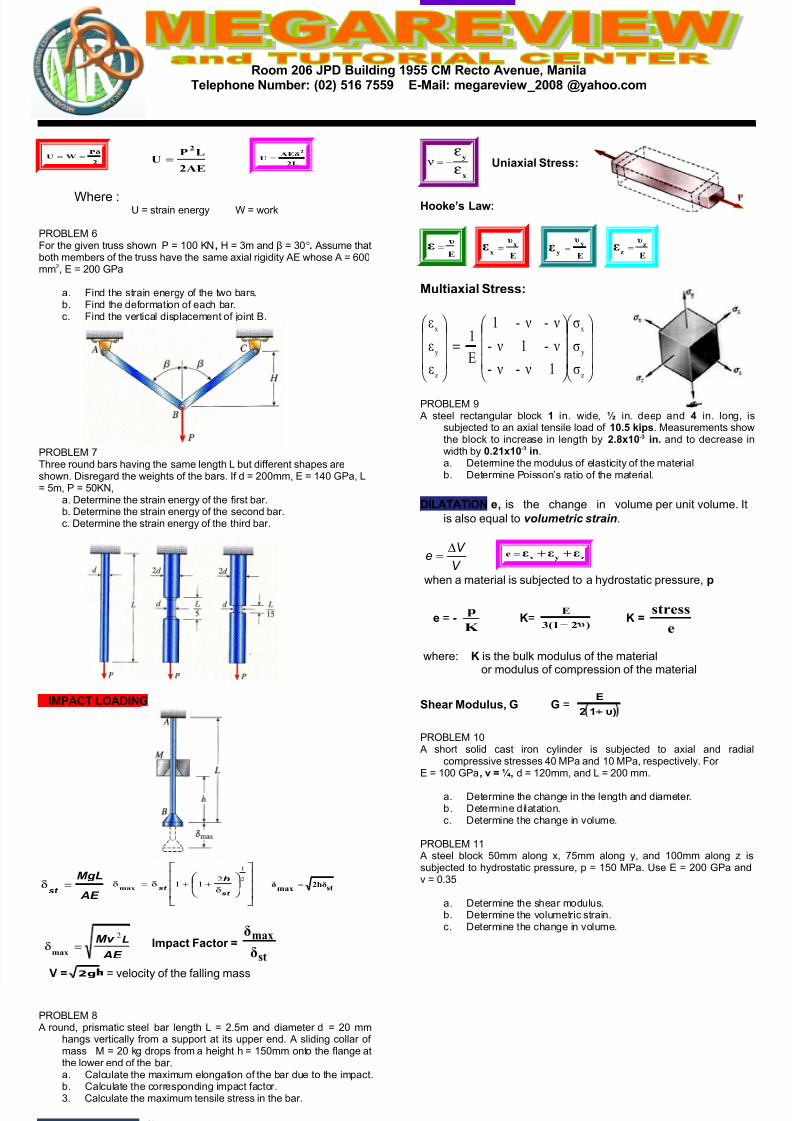
2
PδWU ==
2AE
LPU
2
= 2L
AEδU
2
=
;here :@ ' strain energy ; ' wor+
PRO!"# /6or the given truss shown P ' $)) 89, A ' m and B ' )o/ %ssume thatboth members of the truss have the same a0ial rigidity %" whose % ' /))mm* " ' *)) >Pa
a. 6ind the strain energy of the two bars.b. 6ind the deformation of each bar.c. 6ind the vertical displacement of =oint .
PRO!"# (Three round bars having the same length ! but different shapes areshown. 4isregard the weights of the bars. If d ' *))mm " ' $3) >Pa !' ,m P ' ,)89
a. 4etermine the strain energy of the first bar.b. 4etermine the strain energy of the second bar.c. 4etermine the strain energy of the third bar.
8MPACT ;7AD8!<
AE
MgL
st =δ
δ++δ=δ
2
1
211
st
st
h
max st2hδmax
δ =
AE
Mv L2=δ
max 8mpact acto#
st
max
δ
δ
@ 2g ' velocity of the falling mass
PRO!"# 7 % round prismatic steel bar length ! ' *.,m and diameter d ' *) mm
hangs vertically from a support at its upper end. % sliding collar of mass # ' *) +g drops from a height h ' $,)mm onto the flange atthe lower end of the bar.a. &alculate the ma0imum elongation of the bar due to the impact.b. &alculate the corresponding impact factor.. &alculate the ma0imum tensile stress in the bar.
P787! RAT87 υ ) lateral strain C a0ial strain
x
y
ε
ε−= ν nia=ial t#e33$
?ooe3 ;a*$
E
υε =
E
υx
xε =
E
υy
yε =
E
υz
zε =
Multia=ial t#e33$
=
z
y
x
z
y
x
σ
σ
σ
1 ν- ν-
ν-1 ν-
ν- ν-1
E
1
ε
ε
ε
PRO!"# D % steel rectangular bloc+ 1 in. wide in. deep and in. long is
sub=ected to an a0ial tensile load of 10/5 ip3. #easurements showthe bloc+ to increase in length by 2/=10) in/ and to decrease inwidth by 0/21=10) in.a. 4etermine the modulus of elasticity of the materialb. 4etermine PoissonEs ratio of the material.
D8;ATAT87! e is the change in volume per unit volume. It
is also eual to volumetric strain.
V
eV
∆= zyx
εεεe ++=
when a material is sub=ected to a hydrostatic pressure p
e ' )K
p E'
)21(3
E
υ
E e
stress
where: E is the bul+ modulus of the material or modulus of compression of the material
ea# Modulu3, < < 'F&12
(
PRO!"# $) % short solid cast iron cylinder is sub=ected to a0ial and radial
compressive stresses 3) #Pa and $) #Pa respectively. 6or" ' $)) >Pa, v G, d ' $*)mm and ! ' *)) mm.
a. 4etermine the change in the length and diameter.b. 4etermine dilatation.c. 4etermine the change in volume.
PRO!"# $$ % steel bloc+ ,)mm along 0 (,mm along y and $))mm along ? issub=ected to hydrostatic pressure p ' $,) #Pa. @se " ' *)) >Pa andv ' ).,
a. 4etermine the shear modulus.b. 4etermine the volumetric strain.c. 4etermine the change in volume.