Embed Size (px)
Citation preview
DESIGN ANALYSIS AND STRUCTURAL OPTIMISATION OF A RIGID ANKLE FOOT
ORTHOSIS
MOHD YASHIM WONG PAUL TZE
Master of Science
UNIVERSITI MALAYSIA PAHANG
SUPERVISOR’S DECLARATION
I hereby declare that I have checked this thesis and in my opinion, this thesis is adequate
in terms of scope and quality for the award of the degree of Master of Science.
_______________________________
(Supervisor’s Signature)
Full Name : PROF DR ZAHARI BIN TAHA
Position : PROFESSOR
Date :
_______________________________
(Co-supervisor’s Signature)
Full Name :
Position :
Date :
STUDENT’S DECLARATION
I hereby declare that the work in this thesis is based on my original work except for
quotations and citations which have been duly acknowledged. I also declare that it has
not been previously or concurrently submitted for any other degree at Universiti Malaysia
Pahang or any other institutions.
_______________________________
(Student’s Signature)
Full Name : MOHD YASHIM WONG PAUL TZE
ID Number : MFM14001
Date :

DESIGN ANALYSIS AND STRUCTURAL OPTIMISATION OF A RIGID ANKLE FOOT ORTHOSIS
MOHD YASHIM WONG PAUL TZE
Thesis was submitted in fulfillment of the requirements for the award of the degree of
Master of Science
Faculty of Manufacturing
UNIVERSITI MALAYSIA PAHANG
AUGUST 2018

ii
ACKNOWLEDGEMENTS
First and foremost, my gratitude to Allah SWT the Cherisher and Sustainer of worlds,
Most Gracious, Most Merciful for His countless blessings which had enabled me to
perform this research and to write this thesis to completion. Alhamdulillah.
Deepest gratitude to my supervisor Prof. Dr. Zahari bin Taha for his guidance and
continuous support throughout my Masters research. His insight and advice had altered
the way I perceive research as well as altered my habits to be the best version of a
researcher I could possibly be. Thank you for being patient with my antics throughout
my studies and for not giving up on me when I was at my lowest.
Thank you to all the members of the Innovative Manufacturing, Mechatronics and Sports
(iMAMS) lab be it members of the past and especially present members for their
continuous assistance along the journey of this research. The members have provided
much-needed assistance as well as moral support during the journey and I cannot imagine
completing this study without their assistance.
Special thanks to Universiti Malaya for awarding the High Impact Research Grant which
had provided financial support for this research project.
I would like to extend my heartfelt gratitude to my family; my mother Rosnah binti Mohd
Yassin as well as my father Mohd Yaacob Wong Yong Wen for their continuous
encouragement and financial support throughout my studies.
My wife, Nur Suhaila for always being the light in my darkness, for being there during
all the ups and downs.
iii
ABSTRAK
Ortosis sendi-buku lali (AFO) yang ideal bagi merawat masalah anggota bawah badan adalah ortosis yang diperbuat mengikut acuan antropometri pemakai. Ortosis yang terdapat dipasaran sedia ada kebanyakannya tidak memenuhi ciri ideal tersebut. Namun begitu tidak dinafikan ortosis dipasaran kini mempunyai kos yang rendah. Penghasilan ortosis yang ideal pula, selain melibatkan kos yang tinggi, turut memerlukan masa pembuatan yang panjang kerana darjah kerumitan yang tinggi. Ia juga turut memerlukan kecekapan, ketelitian dan pengalaman yang tinggi seorang tukang ortosis. Bagi menyelesaikan masalah yang dinyatakan tadi, tesis ini mencadangkan satu metodologi rangkakerja menyeluruh bagi pembangunan suatu ortosis dari peringkat rekabentuk hinggalah peringkat pembuatan. Metodologi rangka kerja ini bertujuan untuk menyelesaikan permasalahan kos dan kerumitan proses pembuatan orthosis dengan mengintegrasi solusi berkos rendah ke dalam fasa reka bentuk dan pembuatan. Dalam fasa reka bentuk, untuk mendapatkan ukuran antropometri yang jitu pemakai ortosis satu mesin pengimbas 3D berkos rendah telah digunakan. Data antropometri ini seterusnya digunakan untuk merekabentuk satu prototaip didalam perisian reka bentuk bantuan computer (CAD) komersial Autodesk Inventor. Sebelum prototaip ini direalisasikan melalui mesin pembentukan pengendapan terlakur (FDM), sifat mekanik bahan berdasarkan parameter cetakan perlu dikaji untuk memastikan hasil cetakan yang optimum. Hasil cetakan (Zortrax Acrylonitrile Butadiene Styrene (ABS)) menggunakan parameter cetakan yang berbeza seperti orientasi komponen, ketumpatan dan ketebalan lapisan diuji dengan ujian tegangan untuk mengenal pasti integriti struktur yang signifikan bagi pembuatan ortosis. Berdasarkan hasil ujian ini, parameter percetakan yang optimum dilaksanakan ke dalam Model Unsur Terhad (FEM) untuk mengkaji integriti struktur reka bentuk ortosis tersebut. Penilaian integriti struktur ortosis adalah penting untuk mengkaji ketersauran penggunaan mesin pembentukan pengendapan terlakur (FDM) dalam menghasilkan ortosis. Kajian Model Unsur Terhad (FEM) turut menjalankan pengoptimuman topologi bagi mengurangkan berat ortosis serta meminimumkan penggunaan bahan ketika penghasilan ortosis tanpa menjejaskan integriti struktur ortosis tersebut. Hasil daripada pengoptimuman topologi ini, pengurangkan kos sebanyak 3% dan pengingkatan kekuatan struktur dari faktor keselamatan dari 0.289 ke 4.671 telah dicapai. Berdasarkan keputusan kajian ini, metodologi rangka kerja yang dicadangkan adalah terbukti lebih efisien dalam mengurangkan kos serta meningkatkan kekuatan bagi penghasilan ortosis yang spesifik kepada ukuran antropometri individu.

iv
ABSTRACT
The ideal type of Ankle Foot Orthosis (AFO) for treating patients with lower limb impairments are those that closely follow the wearer’s anthropometry. Most mass-produced AFO that are available in the market does not cater the aforementioned requirements nonetheless it is cost-effective. Conversely, the existing AFO that does conform to individual anthropometry is expensive due to complex geometry, requiring skilled and experienced orthotist. Adding to this cost is the long lead time required to produce a unit of orthosis. In order to mitigate the aforementioned problems of mass produced and individual-specific AFO, this thesis proposes a methodological framework that addresses these issues from the design phase to the fabrication phase. This methodological framework aims to rectify the cost and complexity issue by integrating inexpensive solutions into the design and fabrication stage. In the design phase, a low-cost 3D scanning is adopted to obtain an accurate 3D capture of an individual’s anthropometry. An initial AFO prototype is modelled based on this 3D capture data through the use of a commercially available Computer Aided Design (CAD) software package, Autodesk Inventor. Subsequently a tensile test was performed to investigate different mechanical properties arising from varying printing parameters namely; material orientation, build density and print layer thickness of Zortrax Acrylonitrile Butadiene Styrene (ABS) material which is the material used in the fabrication stage employing the use of a low cost Zotrax M200 3D printer. This experimental investigation is not trivial as it provides significant insight on the mechanical characteristics of the varying parameters mentioned above. Based upon the experimental investigation, the best printing parameters were fed into the Finite Element Model to further investigate the structural integrity of the design as well as to carry out the proposed Topology Optimisation method. The evaluation of the structural integrity is important in order to weigh the feasibility of using the Fused Deposition Modelling (FDM) process in the manufacture of tailor made AFO. A structural optimisation is carried out to reduce the weigh and subsequently the cost of production without comprising the structural integrity of the AFO. From the study, by the implementing structural optimisation, specifically the topology method, the end design exhibits a cost reduction 3% and an actual improvement in structural integrity particularly the factor of safety from 0.289 before optimization to 4.671 after optimization suggesting a marked improvement. Therefore, this study has contributed to the body of knowledge by demonstrating that the proposed methodological framework is sound in the manufacture of individually customised AFO.

v
TABLE OF CONTENT
DECLARATION
TITLE PAGE
ACKNOWLEDGEMENTS ii
ABSTRAK iii
ABSTRACT iv
TABLE OF CONTENT v
LIST OF TABLES viii
LIST OF FIGURES x
LIST OF SYMBOLS xiv
LIST OF ABBREVIATIONS xvi
CHAPTER 1 INTRODUCTION 1
1.1 Background of Research 1
1.2 Problem Statement 3
1.3 Objective of Study 4
1.4 Hypothesis of Study 4
1.5 Thesis Outline 5
CHAPTER 2 LITERATURE REVIEW 6
2.1 Introduction 6
2.2 General Characteristics of Ankle Foot Orthosis 7
2.3 Traditional AFO Design and Fabrication Methods 9
2.4 Additive Manufacturing Methods in AFO Fabrication 11

vi
2.4.1 Selective Laser Sintering (SLS) 13
2.4.2 Fused Deposition Modelling (FDM) 16
2.4.3 Stereolithography (SLA) 18
2.4.4 Comparison of SLS, FDM and SLA Processes in Efficacy of
AFO Fabrication 21
2.5 Structural Optimization 22
2.5.1 Types of Structural Optimization 24
2.5.2 Application of Structural Optimisation in AFO Design 25
2.5.3 Considerations for Implementation of Structural Optimisation for
Parts Fabricated using Fused Deposition Modelling 27
CHAPTER 3 METHODOLOGY 30
3.1 Introduction 30
3.2 Ankle-Foot Region Scanning 31
3.3 FDM Material Characterization 34
3.3.1 Fabrication and Preparation of Specimens 34
3.3.2 Tensile Test Procedures 38
3.4 Modelling of the AFO 40
3.4.1 Geometrical Model 40
3.4.2 Material Properties 44
3.4.3 Boundary Conditions – Loads and Constraints 45
3.5 Topology Optimisation 54
3.6 Cost Model for Fabrication of AFO using the FDM Process 55
CHAPTER 4 RESULTS AND DISCUSSION 60
4.1 Scanned Limb 3D Geometry and Initial AFO Design 60

vii
4.2 Tensile Test Results of FDM Printed Specimens for Different Printing
Parameters 63
4.2.1 Tensile Test Results for Specimens of Different Layer Thickness 63
4.2.2 Tensile Test Results for Specimens of Different Infill Densities 73
4.2.3 Summary of Tensile Test Findings and Selection of Process
Parameters for Fabrication of AFO 79
4.3 AFO Finite Element Analysis 84
4.3.1 Heel Strike Gait Phase AFO FEA Results 84
4.3.2 Midstance Gait Phase AFO FEA Results 86
4.3.3 Push Off Gait Phase AFO FEA Results 89
4.4 AFO Topology Optimization Results 91
4.5 AFO Cost Estimation 94
CHAPTER 5 CONCLUSION 96
5.1 Conclusion 96
5.2 Limitation of Research Work 97
5.3 Recommendations for Future Works 97
REFERENCES 99
APPENDIX A BLACK TO WHITE RATIO MATLAB CODE 105
APPENDIX B ANKLE FOOT ORTHOSIS PROTOTYPE DIMENSIONS 106
APPENDIX C MODULUS OF ELASTICITY – FILAMENT THICKNESS A 107
APPENDIX C MODULUS OF ELASTICITY – FILAMENT THICKNESS B 109
APPENDIX D MODULUS OF ELASTICITY – FILAMENT THICKNESS C 111

viii
LIST OF TABLES
Table 2.1 Summary of Research on the Application of SLS in AFO Fabrication 14
Table 2.2 Summary of Research on the Application of the FDM Process in AFO Fabrication 17
Table 2.3 Summary of Research on the Application of the SLA Process in AFO Fabrication 20
Table 2.4 Comparison of Process Characteristics between SLS, FDM and SLA. Green table shading denotes desirable properties. 21
Table 2.5 Summary of Research Works Applying Structural Optimisation 26
Table 2.6 Summary on Research Investigating Mechanical Properties of Fused Deposition Modelling Components 28
Table 3.1 Microsoft Kinect 360 Technical Specifications 31
Table 3.2 Build Settings Density Calculation Using Black and White Image Mapping Method 37
Table 3.3 Specimen Build Parameters and Specimen Numbers 38
Table 3.4 INSTRON UTS Machine Testing Parameters 39
Table 3.5 Convergence Analysis Settings 41
Table 3.6 AFO Mesh Parameters 43
Table 3.7 Body Mean Segment Weight (Based on Percentage Value, Adapted from (Plagenhoef et al., 1983) for Lower Limb Segments) 46
Table 3.8 Foot Pressure Profile Adapted from. Park et al.'s (2009) 49
Table 3.9 Force Boundary Condition for Mid-stance Phase 52
Table 3.10 Force Boundary Condition for Mid-stance Phase 53
Table 3.11 Topology Optimization Configuration 54
Table 3.12 Mesh Configuration for Topology Optimisation Process 54
Table 4.1 Comparison of Measurements Between Scanned and Actual Limb 60
Table 4.2 Dimensions for Trimline 61
Table 4.3 A-Build Orientation, Low Density Z-ABS Material Properties for Different Layer Thickness (N = 5 Samples for Each Layer Thickness). Values of Properties are of Average Value for 5 Samples. 64
Table 4.4 B-Build Orientation, Low Density Z-ABS Material Properties for Different Layer Thickness (N = 5 Samples for Each Layer Thickness). Values of Properties are of Average Value for 5 Samples. 68
ix
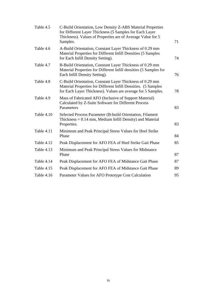
Table 4.5 C-Build Orientation, Low Density Z-ABS Material Properties for Different Layer Thickness (5 Samples for Each Layer Thickness). Values of Properties are of Average Value for 5 Samples. 71
Table 4.6 A-Build Orientation, Constant Layer Thickness of 0.29 mm Material Properties for Different Infill Densities (5 Samples for Each Infill Density Setting). 74
Table 4.7 B-Build Orientation, Constant Layer Thickness of 0.29 mm Material Properties for Different Infill densities (5 Samples for Each Infill Density Setting). 76
Table 4.8 C-Build Orientation, Constant Layer Thickness of 0.29 mm Material Properties for Different Infill Densities. (5 Samples for Each Layer Thickness). Values are average for 5 Samples. 78
Table 4.9 Mass of Fabricated AFO (Inclusive of Support Material) Calculated by Z-Suite Software for Different Process Parameters 83
Table 4.10 Selected Process Parameter (B-build Orientation, Filament Thickness = 0.14 mm, Medium Infill Density) and Material Properties. 83
Table 4.11 Minimum and Peak Principal Stress Values for Heel Strike Phase 84
Table 4.12 Peak Displacement for AFO FEA of Heel Strike Gait Phase 85
Table 4.13 Minimum and Peak Principal Stress Values for Midstance Phase 87
Table 4.14 Peak Displacement for AFO FEA of Midstance Gait Phase 87
Table 4.15 Peak Displacement for AFO FEA of Midstance Gait Phase 89
Table 4.16 Parameter Values for AFO Prototype Cost Calculation 95
x
LIST OF FIGURES
Figure 1.1 Number of 3D Printers (Priced under $5,000) Sold Worldwide From The Year 2007 to 2015. Source: (Wohlers, 2015) 2
Figure 2.1 Flexible AFO (Left) and Limb Movement that FAFO Assists Upon (Right) 7
Figure 2.2 Rigid Ankle Foot Orthosis 8
Figure 2.3 Fabrication Stages for Customised Foot Orthosis 9
Figure 2.4 Measurement Stage in the Fabrication of AFOs from Negative Cast (A) till Positive Cast (F). Source: Becker Orthopedic Appliance (2003) 10
Figure 2.5 Standard Trim Line Dimension for Rigid AFO Source: ICRC (2010) 11
Figure 2.6 Summary of General Additive Manufacturing Steps Source: European Powder Metallurgy Association (2015) 12
Figure 2.7 Selective Laser Sintering Process Schematics Source: Kalyani & Bansal (2016) 13
Figure 2.8 Rigid AFO with Single Strut Designed using Topology Optimisation (Faustini et al., 2008) 15
Figure 2.9 Fused Deposition Modelling (FDM) Process Schematics 16
Figure 2.10 Stereolithography (SLA) Process Schematics 18
Figure 2.11 Fitting of the AFO Fabricated via the Stereolithography Process Source: Mavroidis et al. (2011). 19
Figure 2.12 Sizing Optimization on a Truss Structure Source: Olason & Tidman (2010) 24
Figure 2.13 Shape Optimization on a Structure with Circular Holes Source: Olason & Tidman (2010) 24
Figure 2.14 Topology Optimization Performed on a Structure with only Boundary Parameters Source: Olason & Tidman (2010) 25
Figure 2.15 Mechanical Properties - Tensile Strength [MPa] caused by (a) building direction, (b) infill percentage, (c) printing speed, (d) infill patterns, (e) extrusion temperature and (f) layer height, where E is young's modulus, Sy is the yield strength and Ts is the tensile strength Source: Ahn et al. ( 2002). 27
Figure 2.16 Standardised Axes Used to Describe Build Orientation Across Literature 29
Figure 3.1 Research Flow Chart 30
Figure 3.2 Major Components of a Microsoft 360 Kinect Device 32
Figure 3.3 Kinect 3D Scanning Setup 32
Figure 3.4 Post-Processed 3D Geometry of Scanned Limb 33

xi
Figure 3.5 Foot Anthropometry Measurements 34
Figure 3.6 Zortrax M200 3D Printer 35
Figure 3.7 Tensile Test Specimen Dimensions for Z-ABS Material 35
Figure 3.8 Build Orientations with Respect to AFO and Coordinate System 36
Figure 3.9 Printing Location of Z-ABS Test Specimens 36
Figure 3.10 Infill Density Settings (From Left; Low, Medium and High Settings Respectively) 37
Figure 3.11 Test Specimens Conditioned in a Dry Cabinet with Temperature Control 38
Figure 3.12 INSTRON 3300 UTS Machine and Test Setup 39
Figure 3.13 Parabolic-Tetrahedron Element Nodes (10 Nodes Total) 40
Figure 3.14 Parabolic-Tetrahedron (CTETRA) Element Coordinate System 41
Figure 3.15 Convergence Plot for different Mesh Iterations (Top – Von Mises Stress, Bottom – Displacement) 42
Figure 3.16 Meshed AFO Geometry (From Left; Isometric, Side, Front and Back View Respectively). 44
Figure 3.17: Free-Body Diagram for The Heel Strike Gait Phase 46
Figure 3.18 Free-Body Diagram for the Mid Stance Gait Phase 47
Figure 3.19 Free-Body Diagram for the Push Off Gait Phase 48
Figure 3.20 Obtaining Foot Feature Coordinates from 3D Foot Scan 48
Figure 3.21 Traced Geometry of Scanned Foot. The Yellow Dot Represents the Origin of the Coordinates. 49
Figure 3.22 Foot Pressure Boundary Condition Applied on Midstance Gait Phase FE Model (Left – Top View, Right- Isometric View) 50
Figure 3.23 Location of Fixed Constraint in the AFO Model for the Midstance Gait Phase. 50
Figure 3.24 Obtained Shank Profile (Left-Feature Tracing, Right-Resultant Geometry) 51
Figure 3.25 Location of Force FE Model Definition during Heel Strike Gait Phase 51
Figure 3.26 Loadings and Constraints Applied to Heel Strike Phase AFO FE Model (Left - Fixed Constraint , Right – Loads). 52
Figure 3.27 Location of Force FE Model Definition during Push Off Gait Phase 53
Figure 3.28 Push off Gait Phase FE Model Boundary Conditions 53
Figure 3.29 Boundary Condition for AFO Topology Optimisation 55
Figure 4.1 Dimensions for Construction of Trim line (M. A Arnold, 1999) 61
Figure 4.2 AFO Design Process - Splitting of the Geometries 62

xii
Figure 4.3 Initial Prototype of Ankle Foot Orthosis Designed Based on Scanned Geometry. 62
Figure 4.4 A Build Orientation Specimen Stress-Strain Curves for Layer Thickness of 0.09mm, 0.14mm, 0.19mm and 0.29mm (From top to bottom respectively) 63
Figure 4.5 Direction of Forces, N to A-Build Orientation Filament Arrangement 65
Figure 4.6 Failure Mode of A-Build Orientation for Each Layer Thickness 66
Figure 4.7 B Build Orientation Specimen Stress-Strain Curves for Layer Thickness of 0.09mm, 0.14mm, 0.19mm and 0.29mm (From top to bottom respectively) 67
Figure 4.8 Direction of Forces, N to B-Build Orientation Filament Arrangement 69
Figure 4.9 Failure Mode of B-Build Orientation for Each Layer Thickness 69
Figure 4.10 C Build Orientation Specimen Stress-Strain Curves for Layer Thickness of 0.09mm, 0.14mm, 0.19mm and 0.29mm (From top to bottom respectively) 70
Figure 4.11 Direction of Forces, N to C-Build Orientation Filament Arrangement 71
Figure 4.12 Failure Mode of C-Build Orientation for Each Layer Thickness 72
Figure 4.13 A Orientation Specimen Stress Strain Curves for Low, Medium and High Infill Densities (From top to bottom respectively.) 73
Figure 4.14 B Orientation Specimen Stress Strain Curves for Low, Medium and High Infill Densities (From top to bottom respectively.) 75
Figure 4.15 C-Orientation Specimen Stress Strain Curves for Low, Medium and High Densities (From top to bottom respectively.) 77
Figure 4.16 Average Maximum Stress (MPa) Across Varying Layer Thickness (mm) 79
Figure 4.17 Average Elastic Modulus (MPa) Across Varying Layer Thickness Size (mm) 79
Figure 4.18 Tensile Stress Standard Deviation (MPa) Across Varying Filament Thickness (mm) 80
Figure 4.19 Average Maximum Stress (MPa) Across Varying Infill Density Settings (kg/m3) 80
Figure 4.20 Average Elastic Modulus (MPa) Across Varying Infill density Settings (kg/m3) 81

xiii
Figure 4.21 Tensile Stress Standard Deviation (MPa) Across Varying Infill density Settings (kg/m3) 81
Figure 4.22 Final Printing Geometry with Support Structure Generated by 3D Printer Software (A, B and C Build Orientation Respectively.) 82
Figure 4.23 Von Misses Stress of AFO During Heel Strike Gait Phase 84
Figure 4.24 Displacement of AFO During Heel Strike Gait Phase 85
Figure 4.25 Factor of Safety Plot of AFO During Heel Strike Gait Phase 86
Figure 4.26 Von Misses Stress of AFO During Midstance Gait Phase 87
Figure 4.27 Displacement of AFO During Midstance Gait Phase 88
Figure 4.28 Factor of Safety Plot of AFO During Midstance Gait Phase 88
Figure 4.29 Von Misses Stress of AFO During Push Off Gait Phase 89
Figure 4.30 Displacement of AFO During Push Off Gait Phase 90
Figure 4.31 Factor of Safety Plot of AFO During Heel Strike Gait Phase 90
Figure 4.32 Front View Element Removal Process of the AFO Geometry Across Simulation Time (From Left) till Convergence (Right) 91
Figure 4.33 Side View Element Removal Process of the AFO Geometry Across Simulation Time (From Left) till Convergence (Right) 91
Figure 4.34 Original AFO Geometry (Left) and Optimised Geometry (Right). 92
Figure 4.35 Support Material for Original Geometry (Left) and Optimised Geometry (Right) 92
Figure 4.36 Optimised AFO Von Misses Stress 93
Figure 4.37 Optimised AFO Displacement (Left) and FOS (Right) Plot 94

xiv
LIST OF SYMBOLS
𝐶𝐶𝑒𝑒 Execution Cost
𝐶𝐶𝑓𝑓𝑓𝑓 Prototype Cost
𝐶𝐶𝑚𝑚 Material Cost
𝐶𝐶𝑓𝑓 Processing Cost
𝐶𝐶𝑓𝑓𝑝𝑝 Personal Computer
𝐶𝐶𝑓𝑓𝑓𝑓 Post-Processing Cost
𝐶𝐶𝑠𝑠𝑠𝑠 Software License Cost
𝐹𝐹𝐵𝐵𝐵𝐵 Body Weight Force
𝐹𝐹𝐶𝐶𝐶𝐶𝐶𝐶 Leg to Shank Contact Force
𝐹𝐹𝑅𝑅 Ground Reaction Force
𝐹𝐹𝑎𝑎 Ankle Stabilising Force
𝐿𝐿ℎ𝑖𝑖𝑖𝑖𝑖𝑖 End of Heel Moment Length
𝑀𝑀𝑎𝑎 Ankle Stabilising Moment
𝑀𝑀𝑏𝑏 Push Off Moment
𝑀𝑀𝑚𝑚 Maintenance Cost Per Month
𝑃𝑃𝐶𝐶𝑒𝑒 PC Energy Consumption Hour Rate
𝑃𝑃𝑏𝑏𝑓𝑓 Bowl Price
𝑃𝑃𝑒𝑒 Machine Energy Consumption Rate Per Hour
𝑃𝑃𝑘𝑘ℎ Local Average Energy Specific Cost
𝑃𝑃𝑘𝑘ℎ Local Average Energy Specific Cost
𝑃𝑃𝑚𝑚 Specific Cost Per Model Material Volume
𝑃𝑃𝑚𝑚𝑎𝑎𝑚𝑚 Specific Material Cost Per Spool
𝑃𝑃𝑚𝑚𝑓𝑓 Machine Price
𝑃𝑃𝑠𝑠 Specific Cost Per Support Material Volume
𝑃𝑃𝑢𝑢𝑏𝑏 Energy Consumption Rate Per Hour for the Ultrasonic Bowl
𝑅𝑅𝑥𝑥 Rotation in X-Axis
𝑅𝑅𝑦𝑦 Rotation in Y-Axis
𝑅𝑅𝑧𝑧 Rotation in Z-Axis
𝑆𝑆𝑝𝑝 Soap Cost Per Washing Time at Post-Processing
𝑆𝑆𝑟𝑟 Soap Rate Per Package

xv
𝑇𝑇𝑓𝑓 Designer Processing Time
𝑇𝑇𝑓𝑓𝑚𝑚 Model Permenance Time Inside the Ultrasonic Bowl
𝑇𝑇𝑥𝑥 Translation in X-Axis
𝑇𝑇𝑦𝑦 Translation in Y-Axis
𝑇𝑇𝑧𝑧 Translation in Z-Axis
𝑉𝑉𝑝𝑝 Model/Support Material Volume Per Cartridge
𝑉𝑉𝑚𝑚 Model Volume Utilised
𝑉𝑉𝑠𝑠 Support Volume Utilised
𝑉𝑉𝑚𝑚𝑡𝑡𝑚𝑚𝑎𝑎𝑠𝑠 Total Weight Per Spool
𝑉𝑉𝑢𝑢𝑚𝑚𝑖𝑖𝑠𝑠 Total Material Utilised
𝑊𝑊𝑎𝑎𝑚𝑚 Bowl Availability Time Per Year
𝑊𝑊𝑎𝑎𝑚𝑚 Machine Availability Time Per Year
𝑊𝑊𝑎𝑎𝑚𝑚 PC Availability
𝑚𝑚𝑠𝑠𝑒𝑒𝑙𝑙 Leg Shank Mass
𝑟𝑟𝑓𝑓′ Machine Running Cost Per Hour
𝜃𝜃1 Shank Contact Angel
𝜃𝜃2 Dorsiflexion Angle
𝜎𝜎𝑀𝑀𝑀𝑀𝑀𝑀 Maximum Stress
𝜎𝜎𝑌𝑌𝑌𝑌𝑌𝑌𝑌𝑌𝑌𝑌 Yield Stress
𝜔𝜔0 Operator Cost Per Hour
𝜔𝜔𝑖𝑖 Designer Cost Per Hour
𝐿𝐿 Moment Arm Length

xvi
LIST OF ABBREVIATIONS
ABS Acrylonitrile Butadiene Styrene
AFO Ankle Foot Orthosis
AM Additive Manufacturing
CAD Computer Aided Design
CMM Coordinate Measurement Machine
EMG Electromyography
FDM Fused Deposition Modelling
FEA Finite Element Analysis
PA Polyamide
PC Personal Computer
SLA Stereo lithography
SLS Selective Laser Sintering
SO Structural Optimisation
STL Stereo lithography File Format
UTS Universal Testing System
UV Ultraviolet

99
REFERENCES
Ahn, S., Montero, M., Odell, D., Roundy, S., & Wright, P. K. (2002). Anisotropic material properties of fused deposition modeling ABS. Rapid Prototyping Journal, 8(4), 248–257. https://doi.org/10.1108/13552540210441166
Ashtankar, K. M., Kuthe, A. M., & Rathour, B. S. (2013). Effect of Build Orientation on Mechanical Properties of Rapid Prototyping (Fused Deposition Modelling) Made Acrylonitrile Butadiene Styrene (ABS) Parts. In Volume 11: Emerging Technologies (Vol. 11, p. V011T06A017), 1-7. https://doi.org/10.1115/IMECE2013-63146
Becker Orthopedic Appliance. (2003). Thermoforming Guide.Troy, Michigan: Becker Orthopedic
Belegundu, A., & Chandrupatla, T. (2011). Optimization Concepts and Applications in Engineering. Upper Saddle River, NJ: Prentice Hall.
Bellini, A., & Güçeri, S. (2003). Mechanical characterization of parts fabricated using fused deposition modeling. Rapid Prototyping Journal, 9(4), 252–264. https://doi.org/10.1108/13552540310489631
Bendsoe, M. P., & Bendsoe, M. P. (1995). Optimization of Structural Topology, Shape and Material. Retrieved 12 March, 2017, from http://www.ltu.se/omltu/ledigajobb/d21826/d21828/1.48687
Castiblanco, O., & Shareef, I. (2017). Optimization of StepLock ® Orthotic Knee Joint Design. Procedia Manufacturing, 10, 622-633. doi:10.1016/j.promfg.2017.07.065
Cai, L., Byrd, P., Zhang, H., Schlarman, K., Zhang, Y., Golub, M., & Zhang, J. (2016). Effect of Printing Orientation on Strength of 3D Printed ABS Plastics. TMS 2016: 145thAnnual Meeting & Exhibition: Supplemental Proceedings, 199-204. doi:10.1002/9781119274896.ch25
Center for Economics and Business Research Ltd. (2011). The Economic Impact of Improved Orthotic Services Provision. London: British Healthcare Trades Association.
Das, S. C., Ranganathan, R., & N., M. (2018). Effect of build orientation on the strength and cost of PolyJet 3D printed parts. Rapid Prototyping Journal. doi:10.1108/rpj-08-2016-0137

100
European Powder Metallurgy Association. (2015). Introduction To Additive Manufacturing Technology (1st ed.). Retrieved 21 December, 2016 from https://www.epma.com/640-introduction-to-additive-manufacturing-technology-brochure
Faustini, M. C., Neptune, R. R., Crawford, R. H., & Stanhope, S. J. (2008). Manufacture of Passive Dynamic Ankle–Foot Orthoses Using Selective Laser Sintering. IEEE Transactions on Biomedical Engineering, 55(2), 784-790. https://doi.org/10.1109/tbme.2007.912638
Gibson, I., & Bártolo, P. J. (2011). History of Stereolithographic Process. Boston, MA: Springer. https://doi.org/10.1007/978-0-387-92904-0
Gibson, K. S., Woodburn, J., Porter, D., & Telfer, S. (2014). Functionally optimized orthoses for early rheumatoid arthritis foot disease: A study of mechanisms and patient experience. Arthritis Care and Research, 66(10), 1456–1464. https://doi.org/10.1002/acr.22060
Hawke, F., Burns, J., Radford, J., & du Toit, V. (2008). Custom foot orthoses for the treatment of foot pain: a systematic review. Journal of Foot and Ankle Research, 11(1), 43-46. https://doi.org/10.1186/1757-1146-1-S1-O46
Mello, Martins, Parra, B., Pamplona, Salgado, E., & Seguso, R. (2010). Systematic proposal to calculate price of prototypes manufactured through rapid prototyping an FDM 3D printer in a university lab. Rapid Prototyping Journal, 16(6), 411–416. https://doi.org/10.1108/13552541011083326
Hopkinson, N., & Dickens, P. (2003). Analysis of rapid manufacturing - Using layer manufacturing processes for production. Proceedings of the Institution of Mechanical Engineers, Part C: Journal of Mechanical Engineering Science, 217(1), 31–39. https://doi.org/10.1243/095440603762554596
Hull, C. (1986). United States Patent No. 4,575,330.
ICRC. (2010). Manufacturing Guidelines Ankle-Foot Orthosis. International Committee of the Red Cross, ICRC. Retrieved 3 July, 2016 from https://www.icrc.org/eng/assets/files/other/eng-afo-2010.pdf
Jang, G. W., Kim, K. J., & Kim, Y. Y. (2008). Integrated topology and shape optimization software for compliant MEMS mechanism design. Advances in Engineering Software, 39(1), 1–14. https://doi.org/10.1016/j.advengsoft.2006.12.003

101
Jin, Y. A., Plott, J., Chen, R., Wensman, J., & Shih, A. (2015). Additive manufacturing of custom orthoses and prostheses - A review. Procedia CIRP, 36, 199–204. https://doi.org/10.1016/j.procir.2015.02.125
Jumani, M. S., Shaikh, S., & Khaliqdina, J. H. (2013). Stereolithography Technique for Fabrication of Custom Foot Orthoses: A Cost Benefit Analysis. Sindh University Research Journal - SURJ (Science Series), 45(4), 749–754.
Kalyani, V. L., & Bansal, D. (2016). Future Communication Technology : A Comparison Between Claytronics And 3-D Printing, 564(2015), 8–28. Retrieved from http://oaji.net/articles/2016/2725-1472722726.pdf
Kilian, S., Zander, U., & Talke, F. E. (2003). Suspension modeling and optimization using finite element analysis. Tribology International, 36(4–6), 317–324. https://doi.org/10.1016/S0301-679X(02)00204-9
Krone, R., & Schuster, P. (2006). An Investigation on the Importance of Material Anisotropy in Finite-Element Modeling of the Human Femur. SAE Technical Paper Series, 3(1), 18-24. https://doi.org/10.4271/2006-01-0064
Lin, Y., Lin, K., & Chen, C. (2017). Evaluation of the walking performance between 3D-printed and traditional fabricated ankle-foot orthoses— A prospective study. Gait & Posture, 3(1), 1–2. https://doi.org/10.1016/j.gaitpost.2017.06.471
Marro, A., Bandukwala, T., & Mak, W. (2016). Three-Dimensional Printing and Medical Imaging: A Review of the Methods and Applications. Current Problems in Diagnostic Radiology, 45(1). https://doi.org/10.1067/j.cpradiol.2015.07.009
Martins, E. (2003). Contabilidade de Custos. São Paulo (SP): Atlas.
Matthew, C., Mary-Ellen, A., & Keith, R. (2011). Reliability of capturing foot parameters using digital scanning and the neutral suspension casting technique. Journal of Foot and Ankle Research, 4(1), 9. https://doi.org/10.1186/1757-1146-4-9
Mavroidis, C., Ranky, R. G., Sivak, M. L., Patritti, B. L., DiPisa, J., Caddle, A., Bonato, P. (2011). Patient specific ankle-foot orthoses using rapid prototyping. Journal of Neuro Engineering and Rehabilitation, 8(1), 1. https://doi.org/10.1186/1743-0003-8-1
Olason, A., & Tidman, D. (2010). Methodology for Topology and Shape Optimization in the Design Process, 74 - 106. Göteborg: Chalmers University of Technology.
102
Organisation Internationale de Normalisation (ISO). (1989). Prosthetics and orthotics : vocabulary. Part 1, General terms for external limb prostheses and external orthoses = Prothèses et orthèses : vocabulaire. Partie 1, Termes généraux pour prothèses de membre et orthèses externes. TT - (1st ed.). International standard ISO= Norme internationale ISO; 8549-1; Normes ISO (Organisation internationale de normalisation); 8549-1. TA -. Genève, Switzerland : International Organization for Standardization,.
Palermo, E. (2013). Fused Deposition Modeling: Most Common 3D Printing Method, 2016(11th March). Retrieved March 11, 2017, from http://www.livescience.com/39810-fused-deposition-modeling.html
Pallari, J. H. P., Dalgarno, K. W., & Woodburn, J. (2010). Mass customization of foot orthoses for rheumatoid arthritis using selective laser sintering. IEEE Transactions on Biomedical Engineering, 57(7), 1750–1756. https://doi.org/10.1109/TBME.2010.2044178
Park, J. H., Noh, S. C., Jang, H. S., Yu, W. J., Park, M. K., & Choi, H. H. (2009). The Study of Correlation between Foot-pressure Distribution and Scoliosis. IFMBE Proceedings 13th International Conference on Biomedical Engineering, 974-978. https://doi.org/10.1007/978-3-540-92841-6_241
Peter W. Christensen, A. K. (2009). An Introduction to Structural Optimization. Berlin: Springer Netherland.
Plagenhoef, S., Evans, F. G., & Abdelnour, T. (1983). Anatomical Data for Analyzing Human Motion. Research Quarterly for Exercise and Sport, 54(2), 169–178. https://doi.org/10.1080/02701367.1983.10605290
Pucci, J. U., Christophe, B. R., Sisti, J. A., & Connolly, E. S. (2017). Three-dimensional printing: technologies, applications, and limitations in neurosurgery. Biotechnology Advances, 35(5), 521–529. https://doi.org/10.1016/j.biotechadv.2017.05.007
Rao, N., Wening, J., Hasso, D., Gnanapragasam, G., Perera, P., Srigiriraju, P., & Aruin, A. S. (2014). The Effects of Two Different Ankle-Foot Orthoses on Gait of Patients with Acute Hemiparetic Cerebrovascular Accident. Rehabilitation Research and Practice, 2014, 1–7. https://doi.org/10.1155/2014/301469
Saleh, J. M. (2013). Cost Modelling of Rapid Manufacturing Based Mass Customisation System For Fabrication of Custom Foot Orthoses (Doctoral Dissertation). Retrieved 7 February, 2016, from https://theses.ncl.ac.uk/dspace/handle/10443/2193

103
Schmid, M., Kleijnen, R., Vetterli, M., & Wegener, K. (2017). Influence of the Origin of Polyamide 12 Powder on the Laser Sintering Process and Laser Sintered Parts. Journal of Applied Sciences, 7(5), 462. https://doi.org/10.3390/app7050462
Schrank, E. S., & Stanhope, S. J. (2011). Dimensional accuracy of ankle-foot orthoses constructed by rapid customization and manufacturing framework. Journal of Rehabilitation Research and Development, 48(1), 31–42. https://doi.org/10.1682/JRRD.2009.12.0195
Singh, S., Sachdeva, A., & Sharma, V. S. V. (2012). Investigation of Dimensional Accuracy / Mechanical Properties of Part Produced by Selective Laser Sintering. International Journal of Applied Science and Engineering, 1, 59–68. https://doi.org/10.1081/j.asce.39941
Singiresu S. Rao. (2009). Engineering Optimization: Theory and Practice. New Jersey: John Wiley & Sons
Sutradhar, A., Paulino, G. H., Miller, M. J., & Nguyen, T. H. (2010). Topological optimization for designing patient-specific large craniofacial segmental bone replacements. Proceedings of the National Academy of Sciences, 107(30), 13222–13227. https://doi.org/10.1073/pnas.1001208107
Taha, Z., Aris, M. A., Ahmad, Z., Hassan, M. H. A., & Sahim, N. N. (2013). A Low Cost 3D Foot Scanner for Custom-Made Sports Shoes. Applied Mechanics and Materials, 440, 369–372. https://doi.org/10.4028/www.scientific.net/AMM.440.369
Telfer, S., Abbott, M., Steultjens, M., Rafferty, D., & Woodburn, J. (2013). Dose-response effects of customised foot orthoses on lower limb muscle activity and plantar pressures in pronated foot type. Gait and Posture, 38(3), 443–449. https://doi.org/10.1016/j.gaitpost.2013.01.012
Telfer, S., Pallari, J., Munguia, J., Dalgarno, K., McGeough, M., & Woodburn, J. (2012). Embracing additive manufacture: implications for foot and ankle orthosis design. BMC Musculoskeletal Disorders, 13(1), 84-91. https://doi.org/10.1186/1471-2474-13-84
Telfer, S., & Woodburn, J. (2010). The use of 3D surface scanning for the measurement and assessment of the human foot. Journal of Foot and Ankle Research, 3(1), 19. https://doi.org/10.1186/1757-1146-3-19
Tenaga Nasional Berhad. (2014). TNB Electricity Tariff Rates. Retrieved March 3, 2017, from

104
https://www.tnb.com.my/assets/files/Tariff_Rate_Final_01.Jan.2014.pdf
Trotter, L. C., & Pierrynowski, M. R. (2008). The short-term effectiveness of full-contact custom-made foot orthoses and prefabricated shoe inserts on lower-extremity musculoskeletal pain: a randomized clinical trial. Journal of the American Podiatric Medical Association, 98(5), 357–363. https://doi.org/98/5/357 [pii]
Tymrak, B. M., Kreiger, M., & Pearce, J. M. (2014). Mechanical properties of components fabricated with open-source 3-D printers under realistic environmental conditions. Materials and Design, 58, 242–246. https://doi.org/10.1016/j.matdes.2014.02.038
Upadhyay, K., Dwivedi, R., & Singh, A. K. (2017). Determination and Comparison of the Anisotropic Strengths of Fused Deposition Modelling P400 ABS. Advances in 3D Printing & Additive Manufacturing Technologies, 9-28. https://doi.org/10.1007/978-981-10-0812-2
Vidakis, N., Vairis, A., Petousis, M., Savvakis, K., & Kechagias, J. (2016). Fused Deposition Modelling Parts Tensile Strength Characterisation. Academic Journal of Manufacturing Engineering, 14(2), 87–94.
Walbran, M., Turner, K., & McDaid, A. J. (2016). Customized 3D printed ankle-foot orthosis with adaptable carbon fibre composite spring joint. Cogent Engineering, 3(1), 1–11. https://doi.org/10.1080/23311916.2016.1227022
Wong, M., Wong, D., & Wong, A. (2010). A Review of Ankle Foot Orthotic Interventions for Patients with Stroke. The Internet Journal of Rehabilitation, 1(1), 2-4. https://doi.org/10.5580/26b3
Wong, K. V., & Hernandez, A. (2012). A Review of Additive Manufacturing. ISRN Mechanical Engineering, 2012, 1–10. https://doi.org/10.5402/2012/208760
Xu, F., Wong, Y. S., & Loh, H. T. (2000). Toward generic models for comparative evaluation and process selection in rapid prototyping and manufacturing. (2002). Journal of Manufacturing Systems, 21(6), 471. httsp://doi.org/10.1016/s0278-6125(02)80076-0.
Yasuhiro Mine, Takamichi Takashima, H. F. (2006). Study of the Design Method of an Ankle-Foot-Orthosis. Mechatronics for Safety, Security and Dependability in a New Era. Elsevier Ltd. https://doi.org/10.1016/B978-008044963-0/50007-2