Embed Size (px)
Citation preview

DELIVERY OF THERAPEUTIC
MOLECULES USING ELECTROSPRAYED
POLYMERIC PARTICLES FOR
APPLICATIONS IN TISSUE ENGINEERING
Nathalie Bock
M.Sc.
Submitted in fulfilment of the requirements for the degree of
Doctor of Philosophy
Institute of Health and Biomedical Innovation (IHBI)
Science and Engineering Faculty (SEF)
Queensland University of Technology (QUT)
July 2014

- i -
Abstract
The delivery of growth factors (GFs) from tissue engineered scaffolds is an emerging
strategy for guiding cells towards enhanced regeneration of tissues. Dosage,
however, is critical and GF delivery profiles that mimic natural release profiles are
the holy grail of delivery therapies. Despite this target, currently available products
deliver supraphysiological doses of GFs, generating health concerns associated with
possible tissue formation outside the targeted site and even potential tumour
development. Biodegradable polymeric carriers represent a suitable vehicle for GF
delivery upon matrix degradation, but whilst this is a promising concept in theory, in
practice, processing difficulties arise when encapsulating GFs due to harsh
processing conditions, which in turn may affect GF bioactivity. In this thesis,
electrospraying is hypothesised to be a superior technique to efficiently encapsulate
and reproducibly deliver active GFs from biodegradable polymeric microparticles.
The possibility of dry encapsulation of GFs allows preservation of GF bioactivity
and the identification of key processing parameters enables tailoring of particle size
and morphology, critical in dictating GF release patterns. Firstly, electrospraying was
used to develop polycaprolactone (PCL)- and poly(lactic-co-glycolic acid) 85:15
(PLGA)-based particle formulations containing a model protein, serum albumin (SA)
for optimisation. Following this, the encapsulation of vascular endothelial growth
factor (VEGF) and bone morphogenetic protein-7 (BMP-7), both GFs with proven
effects in bone tissue regeneration, were investigated. The use of poly(ethylene
glycol) (PEG) as an additive within electrosprayed particle formulations was proven
to be efficient in micronising proteins prior to dry encapsulation, and protecting the
bioactivity of GFs. The addition of PEG required optimisation of key variables,
which have been identified to be the electrospraying flow rate coupled with the
polymer solution properties, including concentration and molecular weight. Such
tailoring had a strong effect on particle size distributions, shown to be the most
determinant factor in controlling release profiles, in particular burst release.
Significant difficulties arose during in vitro characterisation due to GF interactions
with other GF molecules and the polymer matrix; this had a marked effect on GF
- ii -
quantification. The use of surfactants in solution was able to partially address this
issue, but may not be sufficient to enable full characterisation of electrosprayed
polymeric particles loaded with GFs. Cells assays were appropriate in assessing GF
bioactivity after various processing steps involved in electrospraying, and showed
that both VEGF and BMP-7 were highly bioactive, even after extended contact with
organic solvent (83% and 98% bioactivity, respectively). When electrosprayed
particles containing BMP-7 were placed in contact with pre-osteoblast cells in vitro,
significant osteogenic differentiation was observed up to three weeks. Finally, melt
electrospun meshes were used as a substrate onto which direct electrospraying of
loaded particles was undertaken, and they were shown to provide an ideal structure
with high porosity and pore size, enabling homogeneous coating throughout the
structure. Electrosprayed particles were shown to be non-toxic in contact with
fibroblast and osteoblast cells and the composite constructs (meshes plus particles)
elicited a positive effect in contact with osteoblast cells, essential pre-requisites for
tissue engineering (TE) applications. This PhD project has contributed new
knowledge for the fabrication and characterisation of electrosprayed particles loaded
with GFs and presents an innovative scaffold design for GF delivery. These findings
are important first steps in applying electrospraying technology in the field of TE,
and demonstrating much promise for the future of GF delivery strategies.
Keywords: albumin, bioactivity, bone morphogenetic protein, controlled release,
drug delivery, electrospraying, encapsulation, growth factor, in vitro characterisation,
melt electrospinning, microfibres, microparticles, microspheres, polycaprolactone,
poly(ethylene glycol), poly(lactic-co-glycolic acid), protein-polymer interactions,
scaffold, vascular endothelial growth factor, tissue engineering.
- iii -
List of Publications
Manuscripts Published
Chapter 2: Electrospraying of Polymers with Therapeutic Molecules: State of the Art
Bock N., Dargaville T. R., Woodruff M. A. (2012)
Progress in Polymer Science 37(11): 1510-1551
Chapter 3: Electrospraying, a Reproducible Method for Production of Polymeric
Microspheres for Biomedical Applications
Bock N., Woodruff M. A., Hutmacher D. W., Dargaville T. R. (2010)
Polymers 3(1): 131-149
Chapter 4: Controlling Microencapsulation and Release of Micronised Proteins
using Poly(Ethylene Glycol) and Electrospraying
Bock N., Dargaville T. R., Woodruff M. A. (2014)
European Journal of Pharmaceutics and Biopharmaceutics - DOI:
10.1016/j.ejpb.2014.03.008
Chapter 6: Composites for Delivery of Therapeutics: Combining Melt Electrospun
Scaffolds with Loaded Electrosprayed Microparticles
Bock N., Woodruff M. A., Steck R., Hutmacher D. W., Farrugia B. L.,
Dargaville T. R. (2014)
Macromolecular Bioscience 14(2): 202-214
- iv -
Scaffolds for Growth Factor Delivery as Applied to Bone Tissue Engineering
Blackwood, K. A., Bock N.*, Dargaville T. R., Woodruff M. A. (2012)
International Journal of Polymer Science - DOI: 17494210.1155/2012/1749
Manuscript Submitted
Chapter 5: Growth Factors Loaded into Electrosprayed Microparticles: Detection
and Bioactivity Discrepancies with In Vitro Assays.
Bock N., Dargaville T. R., Kirby G. T. S., Hutmacher D. W., Woodruff M. A. (2014)
* Co-first author
- v -
List of International Conferences
23rd
Annual Australian Society for Biomaterials and Tissue Engineering
(ASBTE) Conference
AUSTRALIA, Lorne. April 2014.
Bock N., Woodruff M. A., Hutmacher D. W., Dargaville T. R.
Delivery of Growth Factors using Electrosprayed Polymeric Microparticles for
Applications in Bone Tissue Engineering (Oral)
European Society for Biomaterials (ESB) Conference
SPAIN, Madrid. September 2013.
Bock N., Farrugia B. L., Hutmacher D. W., Dargaville T. R., Woodruff M.A.
Polymer Composite Constructs for Drug Delivery: Combining Melt Electrospun
Scaffolds with Electrosprayed Loaded Microparticles (Oral)
ESB Conference
IRELAND, Dublin. September 2011.
Bock N., Dargaville T. R., Hutmacher D. W., Woodruff M. A.
Controlled Release of Bioactive Molecules from PCL Microspheres Produced Using
Electrospraying Technologies (Poster and Short Oral)
ASBTE Conference
NEW ZEALAND, Queenstown. April 2011.
Bock N., Woodruff M. A., Hutmacher D. W., Dargaville T. R.
Electrospraying, a Reproducible Method for Production of Polymeric Microspheres
for Protein Delivery (Oral)
Tissue Engineering and Regenerative Medicine International Society – Asia
Pacific (TERMIS-AP) Conference
AUSTRALIA, Sydney. September 2010.
Bock N., Dargaville T. R., Hutmacher D. W., Woodruff M. A.
Electrospraying, a Reproducible and Non-Toxic Method for Production of
Microspheres Loaded with Growth Factors (Poster)
- vi -
List of Postgraduate Conferences
Australian Society for Medical Research (ASMR) Conference
AUSTRALIA, Brisbane. May 2014.
Bock N., Dargaville T. R., Hutmacher D. W., Woodruff M. A.
Growth-Factor Loaded Electrosprayed Microparticles for Targeted Bone Tissue
Regeneration (Oral)
Institute of Health and Biomedical Innovation (IHBI) Inspires Conference
AUSTRALIA, Brisbane. November 2013.
Bock N., Dargaville T. R., Hutmacher D. W., Woodruff M. A.
Delivery of Therapeutic Molecules using Electrosprayed Polymeric Particles for
Tissue Engineering (Oral)
Royal Australian Chemical Institute (RACI) Queensland, Polymer Group
Student Symposium
AUSTRALIA, Brisbane. November 2013.
Bock N., Woodruff M. A., Hutmacher D. W., Dargaville T. R.
Delivery of Therapeutic Molecules using Electrosprayed Polymeric Particles for
Tissue Engineering (Oral)
IHBI Inspires Conference
AUSTRALIA, Brisbane. November 2011.
Bock N., Dargaville T. R., Hutmacher D. W., Woodruff M. A.
Electrospraying, a Reproducible Method for Production of Polymeric Microspheres
for Protein Delivery (Poster)
RACI Queensland, Polymer Group Student Symposium
AUSTRALIA, Brisbane. August 2011.
Bock N., Woodruff M. A., Hutmacher D. W., Dargaville T. R.
Electrospraying, a Reproducible Method for Production of Polymeric Microspheres
for Protein Delivery (Short Oral)
- vii -
ASMR Conference
AUSTRALIA, Brisbane. May 2011.
Bock N., Woodruff M. A., Hutmacher D. W., Dargaville T. R.
Electrospraying, a Reproducible Method for Production of Polymeric Microspheres
for Protein Delivery (Poster)
IHBI Inspires Conference
AUSTRALIA, Gold Coast. November 2010.
Bock N., Dargaville T. R., Hutmacher D. W., Woodruff M. A.
Electrospraying, a Reproducible Method for Production of Microspheres (Poster)

- viii -
List of Scholarships and Awards
Scholarships
Supervisor Scholarship (2013) – $3,000 pa
Funded by A/Prof. Maria A. Woodruff and Dr. Tim R. Dargaville at Queensland
University of Technology (QUT)
Deputy Vice-Chancellor (DVC)'s Initiative Scholarship (2011-2013) – $6,000 pa
Funded by QUT at QUT
Australian Postgraduate Award (APA) Scholarship (2011-2013) – $22,860 pa
Funded by Dept of Education, Science and Training at QUT
Built Environment and Engineering (BEE) Faculty Living Allowance (2010) –
$22,500 pa
Funded by the Medical Devices Domain of the Institute of Health and Biomedical
Innovation (IHBI) and the Tissue Repair and Regeneration Program at QUT
Awards
ASMR Postgraduate Finalist ASMR Postgraduate
Conference
2014
Travel Award 23rd
ASBTE Conference 2014
Judge’s Prize for Best Oral Presentation,
Runner Up
IHBI Inspires Postgraduate
Conference
2013
Higher Degree Research Student of the
Month Award
Science and Engineering
Faculty (SEF), QUT
2013
PhD Career Start Award, Nominated Women in Technology 2013
Best Student Oral Presentation, 1st place 21
st ASBTE Conference 2011
Travel Award 21st ASBTE Conference 2011
Best Short Oral Presentation, Runner Up RACI Queensland,
Polymer Group Student
Symposium
2011
Outstanding Higher Degree Research
Student of the Month Award
Built Engineering
Environment (BEE)
Faculty, QUT
2010
- ix -
Table of Contents
Abstract ................................................................................................................................ i
List of Publications ............................................................................................................ iii
List of International Conferences ........................................................................................ v
List of Postgraduate Conferences ...................................................................................... vi
List of Scholarships and Awards ..................................................................................... viii
Table of Contents ............................................................................................................... ix
List of Abbreviations ....................................................................................................... xiii
Statement of Original Authorship .................................................................................... xvi
Acknowledgements ......................................................................................................... xvii
CHAPTER 1: GENERAL INTRODUCTION .................................................................... 1
1.1 Overview ...................................................................................................................... 1
1.2 Research Problem ........................................................................................................ 5
1.3 Aims and Outline of the Thesis .................................................................................... 5
1.4 Notes ............................................................................................................................ 6
CHAPTER 2: LITERATURE REVIEW: ELECTROSPRAYING OF POLYMERS
WITH THERAPEUTIC MOLECULES: STATE OF THE ART ...................................... 7
2.1 Abstract ........................................................................................................................ 9
2.2 Keywords ..................................................................................................................... 9
2.3 Introduction .................................................................................................................. 9
2.4 The Technique of Electrospraying ............................................................................. 12
2.4.1 Electrospraying Principles ...............................................................................12
2.4.2 Fabrication Techniques ....................................................................................13
2.5 Control of Particle Characteristics with Electrospraying Parameters ........................ 21
2.5.1 Importance of Electrospraying Parameters ......................................................21
2.5.2 Tailoring of Electrosprayed Particle Characteristics .......................................34
2.6 Electrospraying and Drug Release Characteristics .................................................... 43
2.6.1 Choice of Molecules ........................................................................................43
2.6.2 Loading and Encapsulation ..............................................................................47
2.6.3 Molecule Dispersion ........................................................................................51
2.6.4 Release Kinetics ...............................................................................................54
2.6.5 Denaturation ....................................................................................................64
2.6.6 Bioactivity ........................................................................................................66
2.6.7 In Vivo Performance ........................................................................................69
2.7 The Use of Electrosprayed Particles in Electrospun Scaffolds .................................. 72
2.7.1 Electrospun Nanofibres and Drug Delivery .....................................................72
2.7.2 Electrospun Nanofibres and Particles for Drug Delivery ................................74
2.8 Conclusions ................................................................................................................ 89
2.9 Acknowledgements .................................................................................................... 89
- x -
CHAPTER 3: ELECTROSPRAYING, A REPRODUCIBLE METHOD FOR
PRODUCTION OF POLYMERIC MICROSPHERES FOR BIOMEDICAL
APPLICATIONS .................................................................................................................. 91
3.1 Abstract ..................................................................................................................... 93
3.2 Keywords ................................................................................................................... 94
3.3 Introduction ............................................................................................................... 94
3.4 Experimental Section ................................................................................................. 98
3.4.1 Materials .......................................................................................................... 98
3.4.2 Microsphere Production .................................................................................. 98
3.4.3 Physical Characterisation .............................................................................. 100
3.4.4 Biological Effect of Microspheres ................................................................ 100
3.5 Results and Discussion ............................................................................................ 101
3.5.1 Physical Characterisation .............................................................................. 101
3.5.2 Biological Effect of Microspheres ................................................................ 109
3.6 Conclusions ............................................................................................................. 111
3.7 Acknowledgements ................................................................................................. 112
3.8 References and Notes .............................................................................................. 112
CHAPTER 4: CONTROLLING MICROENCAPSULATION AND RELEASE OF
MICRONISED PROTEINS USING POLY(ETHYLENE GLYCOL) AND
ELECTROSPRAYING...................................................................................................... 113
4.1 Abstract ................................................................................................................... 115
4.2 Keywords ................................................................................................................. 115
4.3 Introduction ............................................................................................................. 115
4.4 Experimental Section ............................................................................................... 118
4.4.1 Materials ........................................................................................................ 118
4.4.2 Particle Fabrication ....................................................................................... 118
4.4.3 Physical Characterisation .............................................................................. 121
4.4.4 In Vitro Characterisation ............................................................................... 121
4.5 Results and Discussion ............................................................................................ 122
4.5.1 Physical Characterisation .............................................................................. 122
4.5.2 In Vitro Characterisation ............................................................................... 136
4.6 Conclusions ............................................................................................................. 142
4.7 Acknowledgements ................................................................................................. 143
CHAPTER 5: GROWTH FACTORS LOADED INTO ELECTROSPRAYED
MICROPARTICLES: DETECTION AND BIOACTIVITY DISCREPANCIES WITH
IN VITRO ASSAYS.. ......................................................................................................... 145
5.1 Abstract ................................................................................................................... 147
5.2 Keywords ................................................................................................................. 147
5.3 Introduction ............................................................................................................. 147
5.4 Experimental Section ............................................................................................... 151
5.4.1 Materials ........................................................................................................ 151
5.4.2 Particle Fabrication ....................................................................................... 151
5.4.3 Particle Characterisation ............................................................................... 152
- xi -
5.4.4 In Vitro Characterisation ................................................................................152
5.4.5 Statistical Analysis .........................................................................................156
5.5 Results ...................................................................................................................... 156
5.5.1 Particle Microstructure ..................................................................................156
5.5.2 GF Encapsulation Efficiency .........................................................................157
5.5.3 GF Recovery through In Vitro Processing .....................................................158
5.5.4 In Vitro GF Release .......................................................................................159
5.5.5 In Vitro GF Bioactivity ..................................................................................160
5.5.6 In Vitro Microparticle 2D Culture .................................................................164
5.6 Discussion ................................................................................................................ 167
5.6.1 GF Quantification with In Vitro Assays ........................................................167
5.6.2 The Use of Surfactants in In Vitro Assays .....................................................168
5.6.3 The Use of Stabilisers in Microparticle Formulations ...................................169
5.6.4 Bioactivity of GF through In Vitro Processing ..............................................171
5.6.5 GF Delivery in an In Vitro 2D Culture ..........................................................172
5.7 Conclusions .............................................................................................................. 173
5.8 Acknowledgements .................................................................................................. 174
5.9 Supporting Information ............................................................................................ 174
5.9.1 Culture Conditions for GF Bioactivity Assessment .......................................174
5.9.2 Particle Microstructure ..................................................................................177
5.9.3 In Vitro GF Release .......................................................................................178
5.9.4 The Effect of Freeze-Drying on BMP-7 ........................................................178
5.9.5 In Vitro Microparticle 2D Culture .................................................................178
CHAPTER 6: COMPOSITES FOR DELIVERY OF THERAPEUTICS:
COMBINING MELT ELECTROSPUN SCAFFOLDS WITH LOADED
ELECTROSPRAYED MICROPARTICLES .................................................................. 181
6.1 Abstract .................................................................................................................... 183
6.2 Keywords ................................................................................................................. 183
6.3 Introduction .............................................................................................................. 183
6.4 Experimental Section ............................................................................................... 185
6.4.1 Scaffold Fabrication .......................................................................................185
6.4.2 Physical Characterisation ...............................................................................186
6.4.3 In Vitro Characterisation ................................................................................187
6.4.4 Biological Evaluation ....................................................................................189
6.5 Results and Discussion ............................................................................................. 190
6.5.1 Fabrication and Physical Characterisation .....................................................190
6.5.2 Protein Release and Polymer Degradation ....................................................195
6.5.3 Biological Effects ..........................................................................................202
6.6 Conclusions .............................................................................................................. 204
6.7 Supporting Information ............................................................................................ 205
6.7.1 Electrospraying Setup ....................................................................................205
6.7.2 Particle Size Distributions and Morphologies ...............................................205
6.7.3 Morphology of Composite Scaffolds .............................................................207
- xii -
6.7.4 Glass Transition ............................................................................................ 208
6.7.5 Molecular Weight, Polydispersity, Mass ...................................................... 208
6.8 Acknowledgements ................................................................................................. 210
CHAPTER 7: SUMMARY AND FUTURE DIRECTIONS .......................................... 211
BIBLIOGRAPHY .............................................................................................................. 217
- xiii -
List of Abbreviations
ALP alkaline phosphatase
ANOVA analysis of variance
AV applied voltage
BDNF brain-derived neurotrophic factor
BDP beclomethasone dipropionate
BMP bone morphogenetic protein
bSOD superoxide dismutase
C6 coumarin-6
CD circular dichroism
Chi chitosan
CLSM confocal laser scanning microscopy
CS chondroitin sulphate
Da Dalton unit (1 Da = 1 g/mol, 1 kDa = 1,000 g/mol )
DCM dichloromethane
DD direct dissolution
DDPS drug delivery particulate systems
DMEM Dulbecco's modified Eagle medium
DMF N,N-dimethylformamide
DMSO dimethyl sulfoxide
DOX doxorubicin
DSC differential scanning calorimetry
DTAB didodecyltrimethylammonium bromide
EBM-20 endothelial media
ECGS endothelial cell growth supplement
ECM extracellular matrix
EE encapsulation efficiency
EGF epidermal growth factor
ELISA enzyme-linked immunosorbent assay
ELP elastin-like polypeptides
EtOH ethanol
EX extraction
FCS foetal calf serum
FDA Food and Drug Administration
FDAC fluorescein diacetate
FITC fluorescein isothiocyanate
FGF fibroblast growth factor
FR flow rate
FTIR Fourier transform infrared
GC group contribution
GPC gel permeation chromatography
GF growth factor
GFR growth factor recovery
H&E hematoxylin and eosin
HA hydroxyapatite
HFIP hexafluoro-2-propanol
HMDS hexamethyldisilazane
HUVEC human umbilical vein endothelial cell
HRP horseradish perodixase
HSP Hansen solubility parameter

- xiv -
HyA hyaluronic acid
HV high voltage
ID internal diameter
IGF-1 insulin-like growth factor-1
IL-1α interleukin 1 alpha
KOW octanol/water partition coefficient
LC loading capacity
LF lung fibroblasts
L:G lactide:glycolide
MPHB methylparahydroxybenzoate
MSC mesenchymal stem cell
µBCA micro-bicinchoninic acid
µCT micro-computed tomography
MW molecular weight
MWD molecular weight distribution
NGF nerve growth factor
NHEF human epidermal fibroblasts
NHEK human epidermal keratinocytes
NIH National Institutes of Health
o/o/w oil-in-oil-in-water
o/w oil-in-water
PAA poly(amidoamines)
PBS phosphate buffer saline
PCL polycaprolactone
PDGF platelet-derived growth factor
PDI polydispersity index
PEG poly(ethylene glycol)
PEO poly(ethylene oxide)
PEUU poly(ester urethane) urea
PI propidium iodide
PLA polylactide
PLACL poly(L-lactic acid)-co-polycaprolactone
PLGA poly(lactic-co-glycolic acid)
PLL poly(ε-carbobenzoxy-L-lysine)
PLLA poly-L-lactide
PMMA poly(methyl methacrylate)
pNP p-nitrophenol
pNPP para-nitrophenyl phosphate
PPE-EA polyamino ethyl ethylene phosphate
P/S penicillin/streptomycin
PS20 polysorbate 20, Tween 20®
PSU polysulfone
PTMC poly(trimethylene carbonate)
PU polyurethane
PUU polyurethaneurea
PVA poly(vinyl alcohol)
PVC poly(vinyl chloride)
RED relative energy difference
Rg, radius of gyration
RHOB rhodamine B
RHOBOEP rhodamine B octadecyl ester perchlorate
RS release study
SA serum albumin
SD standard deviation
SDS sodium dodecyl sulphate
- xv -
SDS-PAGE sodium dodecyl sulphate-polyacrylamide gel electrophoresis
SE standard error
SEM scanning electron microscope
SMC smooth muscle cell
s/o/o solid-in-oil-in-oil
s/o/w solid-in-oil-in-water
SS salbutamol-sulfate
TE tissue engineering
TEC tissue-engineered construct
TET tetracycline hydrochloride
TFE 2,2,2-trifluoroethanol
TGF-β transforming growth factor beta
TPP tripolyphosphate
TTC tip-to-collector
UV ultraviolet
VEGF vascular endothelial growth factor
vWF von Willebrand factor
w/o water-in-oil
w/o/w water-in-oil-in-water
XPS X-ray photoelectron spectroscopy
XRD X-ray diffractometry
% wt Weight per weight percentage
% wt/v Weight per volume percentage

- xvi -
Statement of Original Authorship
The work contained in this thesis has not been previously submitted to meet
requirements for an award at this or any other higher education institution. To the
best of my knowledge and belief, the thesis contains no material previously
published or written by another person except where due reference is made.
Signature:
Date:
QUT Verified Signature

- xvii -
Acknowledgements
I thank my supervisors, Dr. Tim Dargaville and A/Prof. Mia Woodruff, for their
support, encouragement, help and advice throughout my PhD. In particular, I am
grateful for the freedom and trust they granted me since the start, letting me bring the
electrospraying technology in the picture and supporting all of my ideas, both
intellectually and financially. This attitude was very valuable, helping me grow as an
autonomous and confident researcher. Many thanks also go to Prof. Dietmar
Hutmacher, as an inspirational supervisor associated to this project, helping me to
think ‘outside the box’ while envisioning the big picture.
The execution of this PhD would not have been possible without the great facilities
available at IHBI and QUT and their administrative and technical facilitators; they
hold a great part in making the work pleasant and fruitful. Numerous sources of
funding which are mentioned hereafter are also part of this PhD success, but in
particular I would like to thank the Australasian Society of Biomaterials and Tissue
Engineering for funding my travel to their annual conference in New Zealand in
2011, which was a highlight of this PhD with excellent scientific brainstorming and
remarkable good fun with fellow scientists.
I also thank the members of the Regenerative Medicine group, Biomaterials and
Tissue Morphology group, Tissue Regeneration and Repair group and IHBI
community for advice, help, inspiration and companionship. In particular, thanks to
Brooke Farrugia, for being an amazing friend, attentive listener, and perspicacious
advisor in both my personal life and laboratory undertakings, always there for me
when things hit a rough patch.
Coming from Europe and doing a PhD in Australia was not the easiest decision to
make, but I thank my family for understanding and supporting this choice. Here is
the place and time to acknowledge the education I received from them all, but in
particular from my parents, Pascale and Patrick, and grand-mother Simone (dec.),
which brought me here today. I thank them for trusting and supporting my choices,
encouraging me achieve challenges that sounded impossible for women in their

- xviii -
times. Also thanks to my sister and goddaughter, Mélanie and Espérance, for helping
in keeping this whole doctorate thing not too serious.
Finally, I want to express my most profound gratitude to my partner Luigi, for his
unconditional love, patience, support, encouragement and scientific advice over the
last ten years. Going through a PhD together and holding a common passion for
materials (thanks to EEIGM) made the experience incredibly rich and gave me a lot
of strength. I thank him for always believing in me in any situation and making me
believe that I could achieve anything. Having a child together during this PhD was
something I could not have done without Luigi’s precious qualities and he made the
journey easy, natural and marvellous.
Last, but not least, I thank my son Owen for being the biggest joy in my life. His
good nature and all the wonderful moments we spent together made this time in
Australia a priceless treasure that I will cherish forever, thank you!
- 1 -
Chapter 1: General Introduction
1.1 OVERVIEW
Towards the end of the past millenary, the most significant science discoveries have
paved the way to a progressive but tremendous improvement in the quality of life of
the human species. From the discovery of the cell in the 17th
century by Hooke,
followed by the principle of mass conservation by Lavoisier in the 18th
century, the
19th
century was then the cradle of electromagnetism and thermodynamics laws,
opening the horizons of physics, chemistry and materials sciences, which were
completely rethought throughout the 20th
century. Biological and medical
breakthroughs overflew the last half of the 20th
century, with the discovery of the
structure of DNA, various vaccines and other key discoveries in molecular biology.
At the dawn of the 21st century, the map of genetic information for humans has been
completed, providing insights into one of the major challenges of this new millenary;
the diagnosis and treatment of diseases.
Health concerns are an increasing burden in today’s world, where an ageing
population with unhealthier lifestyle is most likely to face injury, trauma,
degenerative diseases, or tumours in the course of their lifetime. Thanks to the
progresses of science, it is now possible with the medical technologies available
today, to evaluate, treat, augment or replace faulty tissues, organs or functions in the
body by the implantation of materials intended to interface with biological systems
[1]. These materials are termed ‘biomaterials’ and imply a non-toxic response from
the human body. However, while the quality of life of many people has been
improved by biomaterials, most materials are still inert and non-resorbable, made of
metallic, polymeric, or ceramic materials and used as temporary or permanent
prosthesis, which will never perform as well as the natural, original tissue or organ.
Transplantation has shown to be another alternative to tissue repair but is associated
with limited availability and immunological rejection, when coming from another
donor. This increasing need for better therapies has driven the commencement of
tissue engineering therapies in the 1980s [2].
Chapter 1 General Introduction
- 2 -
The concept of tissue engineering (TE) was first introduced by Langer and
Vacanti and refers to a relatively new and interdisciplinary field that applies the
principles of engineering sciences and life sciences [3]. Tissue engineering aims to
develop constructs that promote the repair, restoration or regeneration of cells or
tissues by combining a matrix, often bio-resorbable, with living cells or therapeutic
molecules [4]. The strategies for TE include the growth of functional tissues in vitro
or the regeneration of tissues in vivo and they are aimed at treating skeletal tissues
like bone and cartilage, neural tissue, muscle tissue in the heart, smooth and skeletal
areas, liver tissue and skin [5].
Growth factors (GFs) are central molecules during natural tissue formation and
repair. Cells secrete these polypeptidic molecules in situ to modulate cellular
activities, and a complex and orchestrated delivery of numerous GFs have been
shown to direct tissue growth [6]. GFs are either released on external stimuli for
immediate signalling or are embedded in the extracellular matrix (ECM) and further
released as the ECM degrades [7]. The GFs initiate their action by binding to specific
receptors on the surface of target cells [6] and this action can further activate various
responses, such as directing the phenotype of certain cells, triggering their
proliferation, activating macrophage action and inducing morphogenesis [5, 7]. For
example, while vascular endothelial GF (VEGF) and platelet-derived GF (PDGF)
induce angiogenesis (the formation and maturation of blood vessels) fibroblast GF
(FGF), keratinocyte GF (KGF), interleukin 1 alpha (IL-1α) are involved in skin
regeneration, and bone morphogenetic proteins (BMPs) such as BMP-2 and BMP-7
and transforming GF beta (TGF-β) are key molecules in bone regeneration. The
presence of GFs can be traced during the formation or repair of every tissue within
the body [5] and act in a concentration- and time-dependent manner, often requiring
minute quantities to elicit biological activity [7]. In the case of tissue repair, it is the
repair progress that triggers and controls the timing and location of GF release [5].
Tissue engineers are thus faced with the significant challenge of providing systems
that mimic the natural GF production in a spatial and temporal manner [5].
Current technologies enable GFs to be recombinantly constructed by host
organisms in vitro, at very high cost, but in clinical practice, only a few GFs have
been authorised by regulatory federal agencies, such as the American Food and Drug
Administration (FDA). Approved products include PDGF for the treatments of
diabetic foot ulcers [8] and BMP-2 and BMP-7 for oral maxillofacial applications
Section 1.1 Overview
- 3 -
and spinal fusion [9]. Those products use supra-physiological amounts delivered
from a biodegradable carrier, to obtain a substantial healing response, since GFs have
a short half-life in solution. For example, two products from the market leaders in
orthopaedic GF delivery, Medtronic and Olympus, provide several milligrams of
recombinant BMP-2 (INFUSE®) and BMP-7 (OP-1®), respectively, reconstituted
and added to a collagen sponge immediately prior to implantation into a bone defect
site, in the clinic. Only nanogram levels are actually required to stimulate cells,
hence the massive dose of BMPs present in the sponges, that diffuse away from the
site within minutes of implantation, create increased cost and may lead to
complications [7-11]. BMPs are a potent stimulator of bone formation [12] and
because every cell in the body presents a BMP receptor, there is a serious concern
that BMPs could cause bone to form outside the fusion area (ectopic bone
formation), in places where it may be harmful. These safety concerns were feverishly
brought to light in 2011 with an entire issue of the Spine journal dedicated to the
BMP debate, where it is generally acknowledged that these dangers are associated
with high doses and off label use [13-15].
Several strategies have been implemented to deliver physiologically relevant
quantities of GFs by using polymeric systems intended to encapsulate and deliver
GFs in a sustained and controlled manner, while at the same time protecting the GFs
from their environment [6, 7, 16, 17]. These systems include biodegradable
microspheres, hydrogels, porous soft scaffolds and three dimensional (3D) hard
scaffolds, and can be made from natural or synthetic polymers [17, 18]. The choice
of matrix is important to the success of the tissue-engineered construct and often
fibre-based scaffolds have been used; nanofibres in particular can mimic the
architecture of natural tissue constituents like collagen [19]. Fibre scaffolds, in
general, provide favourable chemical and topographical structures for cells to attach
and proliferate but also favourable physical properties, such as porosity and
interconnectivity for cell infiltration and maturation into a specific tissue [20, 21].
Their lack of biological stimulation has been addressed by tissue-inductive coatings
or incorporation of GFs directly into the fibres, available for cellular uptake upon
matrix degradation [22-24]. However, GFs should ideally be sustainably released
over many weeks, while the fibre construct can still maintain its structural function
[25]. The addition of GFs directly into fibres also leads to deteriorated mesh
properties which, taken collectively, may lead to non-optimum constructs. To
Chapter 1 General Introduction
- 4 -
overcome these limitations, the addition of a separate release system to a fibre
scaffold represents a more suitable solution, allowing the tailoring of the release
system separately from the scaffold [24].
The use of biodegradable microparticles, in particular, has shown a lot of potential
for GF delivery applications [17, 18]; they somewhat mimic cells by releasing
smaller but more effective amounts of GFs, closer to physiological doses [18]. Many
techniques exist for producing GF-loaded particles with emulsion/evaporation-based
methods being the most extensively used [26]. However, to date, very few of these
techniques have been effectively translated to the clinic. This lack of translational
research is mainly attributed to shortfalls associated with conventional production
methods, including GF degradation during processing, mostly due to the use of
organic solvents and emulsions [11]. Electrospraying is rapidly emerging as a
potentially superior technology for the production of polymeric particles containing
therapeutic molecules, able to reduce denaturation of proteins and drugs [27].
Electrospraying also affords enhanced regulation over particle size/morphology,
which is essential in controlling release profiles. While the concept of
electrospraying is relatively simple, involving electrohydrodynamic atomization of a
polymer solution [28], understanding and optimising the technique is still in its early
years in respect to biological loading, with less than 100 reports in the last 20 years.
Most studies focus on small molecule drugs for antibiotic, anti-cancer, anti-
inflammatory and asthma treatments and few reports are on proteins, and even less
on growth factors (less than 10 [29-33]) mostly for angiogenic and chrondrogenic
applications. Proteins and growth factors are, however, fundamentally different
structures from small molecule drugs, with an increased degree of complexity, due to
their polypeptidic structure, and may trigger different behaviours when loaded and
delivered from electrosprayed particles. Importantly with electrospraying, the
technique allows for dry encapsulation of GFs, which is now recognised to better
maintain GF activity during processing and delivery [34, 35].
The development of electrosprayed particles reproducibly loaded with GFs
relevant to bone tissue may be an appropriate alternative to the current products in
the market, by delivering physiological doses of active BMPs over time, in a
reproducible way. The versatility of electrospraying may enable tailoring of specific
release profiles for different GFs and applications, while delivering fully active GFs
to the injury site, in turn lowering the initial dose needed. This should result in a
Section 1.2 Research Problem
- 5 -
decrease of the associated complications arising when patients receive a ‘critically
too high’ dose of GFs, enhancing the treatments of musculoskeletal disorders. The
use of a fibre scaffold as a carrier for this release system may be particularly
beneficial for this application, where a soft mesh containing GF-loaded particles may
drape the surface of a defected bone for disease treatment or may be integrated in a
bone substitute for bone regeneration, following injury or trauma.
1.2 RESEARCH PROBLEM
In this thesis, it is hypothesised that the electrospraying technology may be used to
produce biodegradable microparticles encapsulating and delivering growth factors
relevant in bone tissue engineering.
1.3 AIMS AND OUTLINE OF THE THESIS
The research problem of this thesis will be addressed by the following aims:
understanding and tailoring the processing parameters involved in
electrosprayed particle formation,
developing electrosprayed particle formulations for reproducible and efficient
GF encapsulation,
characterising GF-loaded formulations for in vitro release and bioactivity,
investigating the potential of loaded electrosprayed microparticles used in
association with a porous fibre scaffold in vitro, as a suitable construct for
tissue engineering.
In this thesis, Chapter 1 introduces the background, rationale and aims of delivering
growth factors using electrosprayed polymeric particles for applications in tissue
engineering. Chapter 2 reviews the literature on this topic, reporting the principles
of the electrospraying technique and presenting the characteristics of particles loaded
with therapeutic molecules, from a physical, pharmaceutical and biological
perspective. In addition, the use of electrosprayed particles in fibre scaffolds for
tissue engineering is reported. Chapters 3 to 6 consist of the experimental chapters
that cover different aspects of the thesis topic. The first objective is the
understanding of reproducible microparticle production via electrospraying, hence
Chapter 3 details the production and optimisation of GF-free electrosprayed
Chapter 1 General Introduction
- 6 -
polycaprolactone (PCL) microparticles. Key parameters are identified with regards to
reproducibility and control of particle size and morphology. Furthermore,
cytocompatibility of optimised microparticles is assessed in vitro. The next step
involves encapsulation of proteins, as model GFs, into electrosprayed microparticles,
which is the focus of Chapter 4. This chapter investigates the use of PCL and
poly(lactic-co-glycolic acid) (PLGA) in association with an additive; poly(ethylene
glycol) (PEG), for the encapsulation of a model protein, serum albumin (SA). The
influence of PEG on the physical and in vitro characteristics of loaded microparticles
is discussed. In Chapter 5, the optimised encapsulation technique with PEG is
extended to encapsulating GFs relevant in bone tissue engineering; namely VEGF
and BMP-7. The release, detection and bioactivity of GFs are assessed in vitro with
an emphasis on GF interactions with the environment. Finally, the application of
loaded electrosprayed particles in tissue engineering is addressed in Chapter 6. This
final experimental chapter describes the fabrication of a new type of composite
scaffold comprising PCL microfibres produced by melt electrospinning and
electrosprayed PLGA microparticles loaded with SA. The composites are
characterised by their physical and degradation properties, and for their ability to
support cell growth in vitro. To conclude, Chapter 7 summaries the findings of the
thesis and provides an outlook on the research topic, looking to the future.
1.4 NOTES
This thesis is presented by publications, where chapters 2, 3, 4 and 6 have already
been published and chapter 5 is under review. Due to the layout required for thesis
by published papers, a few alterations from the published versions have been made
for ease of the reader. These changes include:
renumbering of figures and tables,
change of American spelling to British spelling,
compilation of all references into one combined list for the entire thesis,
homogenisation of abbreviations and units for consistency,
minor additions to emphasise specific points relevant to the thesis topic.
- 7 -
Chapter 2: Literature Review:
Electrospraying of Polymers with
Therapeutic Molecules: State of the Art
Nathalie Bock1,2,3
, Tim R. Dargaville1, Maria A. Woodruff
2
Published in Progress in Polymer Science, Volume 37, Issue 11, 2012, Pages 1510-
1551.
© 2012 Elsevier Ltd. All rights reserved.
Statement of contribution of co-authors for thesis by published papers
Contributors Statement of contribution
Nathalie Bock Searched and read the literature
Designed the review outline
Wrote the manuscript
Tim R. Dargaville* Involved in the conception of the project
Provided feedback on manuscript
Maria A. Woodruff* Involved in the conception of the project
Provided feedback on manuscript
1 Tissue Repair and Regeneration Group
2 Biomaterials and Tissue Morphology Group
3 Regenerative Medicine Group
Institute of Health and Biomedical Innovation, Queensland University of Technology,
60 Musk Avenue, Kelvin Grove, QLD 4059, Australia
Chapter 2 A Literature Review on Electrospraying Applied to Tissue Engineering
- 8 -
The authors listed above have certified* that:
1. they meet the criteria for authorship in that they have participated in the
conception, execution, or interpretation, of at least that part of the publication in
their field of expertise;
2. they take public responsibility for their part of the publication, except for the
responsible author who accepts overall responsibility for the publication;
3. there are no other authors of the publication according to these criteria;
4. potential conflicts of interest have been disclosed to (a) granting bodies, (b) the
editor or publisher of journals or other publications, and (c) the head of the
responsible academic unit, and
5. they agree to the use of the publication in the student’s thesis and its publication
on the QUT ePrints database consistent with any limitations set by publisher
requirements.
Principal Supervisor Confirmation
I have sighted email or other correspondence from all Co-authors confirming their
certifying authorship.
Section 2.1 Abstract
- 9 -
2.1 ABSTRACT
The encapsulation and release of bioactive molecules from polymeric vehicles
represents the holy grail of drug and growth factor delivery therapies, whereby
sustained and controlled release is crucial in eliciting a positive therapeutic effect. To
this end, electrospraying is rapidly emerging as a popular technology for the
production of polymeric particles containing bioactive molecules. Compared with
traditional emulsion fabrication techniques, electrospraying has the potential to
reduce denaturation of protein drugs and affords tighter regulation over particle size
distribution and morphology. In this article, we review the importance of
the electrospraying parameters that enable reproducible tailoring of the particles’
physical and in vitro drug release characteristics, along with discussion of existing in
vivo data. Controlled morphology and monodispersity of particles can be achieved
with electrospraying, with high encapsulation efficiencies and without
unfavourable denaturation of bioactive molecules throughout the process. Finally, the
combination of electrospraying with electrospun scaffolds, with an emphasis on
tissue regeneration is reviewed, depicting a technique in its relative infancy but
holding great promise for the future of regenerative medicine.
2.2 KEYWORDS
Electrospraying, microparticles, encapsulation, drug delivery, controlled release,
tissue engineering, electrospinning.
2.3 INTRODUCTION
The need for controlled delivery of therapeutic molecules has prompted the
investigation of polymeric particles as biodegradable reservoirs which are designed
to degrade at a determined rate, thereby releasing their encapsulated molecules for
sustained and site-specific delivery [17, 18]. This approach could potentially
overcome the limitations of bolus delivery and has drawn much research attention in
the last decades, particularly in the fields of cancer therapies, hormonal treatments,
asthma delivery, and tissue engineering, for which tailored and multiple-molecule
delivery is necessary for therapeutic effect [36]. Many techniques exist for producing
these drug delivery particulate systems (DDPS) with emulsion/evaporation-based
Chapter 2 A Literature Review on Electrospraying Applied to Tissue Engineering
- 10 -
methods being the most extensively used [26]. In this context, the term ‘drug’ refers
to any type of molecule that has a therapeutic effect. Coacervation, spray-drying,
nanoprecipitation and microfluidics are additional techniques each presenting their
own specific advantages and they are broadly described in the literature [37-40].
However, to date, very few of the DDPS generated using these techniques have been
effectively translated to the clinic, with few devices being commercialised each year.
This lack of translational research is mainly attributed to several shortfalls associated
with these production methods [11]. For instance, there are issues surrounding
molecule degradation (such as denaturation of proteins) and instability during the
processes. In emulsion techniques, the aqueous/organic interface and shear stresses
are the first source of limitation [35]. Moreover, entrapped molecules differ in terms
of therapeutic function and physicochemical properties, demonstrating a different
degree of stability and sensitivity to stress. In other techniques, prolonged exposure
to organic solvents and residual traces of solvents or other processing agents in the
final DDPS are of concern. Such factors can affect the nature and stability of the
encapsulated therapeutic molecules, limiting their performance both in vitro and in
vivo, and thus limiting their clinical use. Furthermore, different applications require
different therapeutic molecule release profiles matching the need of a specific treated
tissue, and ideally mimicking the in vivo release profiles generated by the cells from
such tissues. For this to happen, it is critical to have a thorough grasp of the complex
interplay of fabrication parameters which govern the resultant particle characteristics.
Particle size and morphology for example ultimately dictate the degradation, and
hence release profiles from DDPS, although it should be noted that tight control is
currently limited in the traditional fabrication techniques.
One approach to overcome these drawbacks is the technique of electrospraying.
Although electrospraying is a well-established technique in the field of mass
spectrometry and ink-jet printing, it has only been applied to the loading of
therapeutic molecules in the last 20 years and its understanding and optimisation are
still in their relative infancy with respect to biological loading [27, 28, 41]. Briefly,
in electrospraying, a high voltage is applied to a liquid infused through a capillary
nozzle. The electric charge generated on the droplet competes with the surface
tension of the droplet, causing the droplet to break up in nano- to micro-droplets,
which undergo solvent evaporation. The resulting dried particles can then be
collected [42]. Therapeutic molecules can be incorporated into the polymer solution
Section 2.3 Introduction
- 11 -
prior to electrospraying resulting in loaded particles. There are numerous advantages
to electrospraying including the following: the use of an emulsion is optional but not
required; there is no use of high temperature such as in spray-drying; there is no
further drying step required since particles are instantaneously dried during the
process; and there is an enhanced control over the size distribution of particles with
the possibility of producing quasi-monodisperse particles [43]. The latter is
particularly desirable in drug delivery since monodispersity provides more
controlled, and hence reproducible release profiles, which may in turn be more easily
customised for a desired application [44]. Furthermore, in the specific case of
nanoparticles, size affects cellular uptake and thus uncontrolled size distribution may
lead to different biological responses [45, 46]. Control of size is thus of paramount
importance when producing loaded polymeric particles and electrospraying is a
technique which can provide such control over and above that achieved with
traditional techniques, when appropriate parameters are used [47].
Electrospraying also holds potential to reduce denaturation by limiting exposure
to organic solvents and is highly versatile in terms of the choice of polymers,
apparatus, and therapeutic molecules. For instance, if the therapeutic molecule is
highly sensitive to solvents, such as enzymes and DNA molecules, coaxial
electrospraying may be employed. In this way, core-shell capsules are formed and
the protein resides in the core of the capsule in an aqueous solution while the
polymer matrix composes the shell of the capsule [48]. Finally, although
electrospraying through one nozzle has a low throughput, the flexibility of the
technique would enable the use of several nozzles in parallel for a multiplexed
system, ideal for scale-up [49, 50]. To date, therapeutic molecules such as antibiotics
(ampicillin [51], rifampicin [52]), anti-cancer agents (paclitaxel [53-60], doxorubicin
[61], suramin [58], cisplatin [62]), inhalation drugs (beclomethasone dipropionate
(BDP) [63], salbutamol-sulfate (SS) [64]), anti-inflammatory drugs (celecoxib [65],
budesonide [66], naproxen [67]), drugs for hormonal treatments (β-oestradiol [68],
tamoxifen [69, 70]), model proteins (serum albumin (SA) [71-74]) and growth
factors (GFs) (insulin-like GF-1 (IGF-1) [29], vascular endothelial growth factor
(VEGF) and platelet-derived GF (PDGF) [30]) have been loaded in electrosprayed
particles and these studies will be discussed hereafter.
Here we present a comprehensive review of the current state of the art in
electrospraying technology for the controlled release of therapeutic molecules from
Chapter 2 A Literature Review on Electrospraying Applied to Tissue Engineering
- 12 -
polymeric particles. We review the methods used for producing electrosprayed
particles and encapsulating therapeutic molecules, including important
considerations to enable both the physical properties and in vitro drug release
profiles of the particles to be tailored and optimised. The focus of the review is on in
vitro data since very little in vivo data is available yet in the literature, although
discussion of existing in vivo data is also provided. The various applications of
electrospraying with electrospinning technologies, with an emphasis on tissue
engineering, are also reviewed, for a portrayal of the latest techniques used to
produce scaffolds in the diverse and fascinating field of regenerative medicine.
2.4 THE TECHNIQUE OF ELECTROSPRAYING
2.4.1 Electrospraying Principles
Electrospraying is a method of liquid atomization, also known as
electrohydrodynamic atomization. The principle of electrospraying is based on the
theory of charged droplets; stating that an electric field applied to a liquid droplet
exiting a capillary is able to deform the interface of the droplet [28]. The electric
charge generates an electrostatic force inside the droplet which competes with the
surface tension of the droplet, forming the Taylor cone, characteristic of a charged
droplet. Eventually, the electrostatic force, generated by the use of high voltage on
the capillary, is able to overcome the surface tension of the droplet. The excess
charge then needs to be dissipated and smaller charged droplets on the micro to
nano-scale are ejected from the primary droplet, thus reducing its charge without
significantly reducing its mass. Due to Coulomb repulsion of the charges, the
droplets disperse well and do not coalesce during their flight towards the collector
[43]. Several spraying modes can occur during electrospraying; the most desired
being the single cone-jet mode, due to its stability and reproducibility [42].
The various theories of electrospraying physics have been summarised elsewhere
with reviews on the recent advances and applications of the technology [27, 28]
however limited literature exists pertaining to theoretical and practical inclusion of
bioactive molecules in this process. Briefly, the two major parameters that
characterise the electrosprayed aerosol are the size of droplets and electric charge.
The latter is difficult to determine, due to parasitic electrical discharge, although the
Section 2.4 The Technique of Electrospraying
- 13 -
maximum surface charge of a droplet, q, has been identified as a function of the
surface tension, γ, and radius of droplet, R, expressed in Equation 2.1 [75]:
√ (2.1)
From the surface charge, the Rayleigh limit, LR, can be identified, which
determines the charge leading to droplet break-up (Coulomb fission) and is
expressed in Equation 2.2, where ε is the permittivity of the surrounding medium:
( ) (2.2)
Coulomb fission is an unwanted phenomenon by which the charged
electrosprayed droplet emits a cloud of small highly charged droplets, called
‘offsprings’. This occurs if the droplet holds more charge than the Rayleigh limit, as
determined by electrical stresses and surface tension. Droplets produced by
electrospraying are highly charged, usually close to half of the Rayleigh limit [28].
Similarly, the jet break-up mechanism is shown to be dependent on the ratio of
the electrical normal stress over the surface tension stress. It is dependent on the
viscosity and surface charge as in the Rayleigh limit (Equation 2.2), but also on the
acceleration of the jet. With increasing flow rate, the current increases and the stress
ratio of the jet increases, above a threshold value whereby the jet starts to whip,
leading to the production of heterogeneously sized droplets. Ideally, a sufficient
stress ratio value must be employed to allow for jet break-up, but still a minimal
value must be obtained for limiting droplet break-up for production of monodisperse
and homogeneous particles [42].
2.4.2 Fabrication Techniques
The electrospraying setup can be simple and inexpensive; a polymer solution is
loaded into a syringe fitted with a conductive nozzle, and infused at a desired rate
generally implemented by a syringe pump. The nozzle is subjected to high voltage
(in the order of kilovolts and mostly positive) and various types of collectors, often
grounded or more rarely negatively charged, are placed at a distance ranging from a
few centimetres to several tens of centimetres from the nozzle. Once the droplets are
ejected from the Taylor cone according to the theory of charged droplets, solvent
evaporation leads to the progressive contraction and solidification of droplets
resulting in solid polymeric particles impacting onto the collector. While particles are
Chapter 2 A Literature Review on Electrospraying Applied to Tissue Engineering
- 14 -
generally assumed to be dry or proven to contain residual solvent falling within the
limit of safety standards [76], many studies also use subsequent vacuum treatment to
ensure all residual solvent is removed. In the context of loading, the biologically
active molecule (biomolecule) is generally mixed into the polymer solution before
electrospraying; this approach is covered in section 2.4.2.2.
2.4.2.1 Electrospraying Apparatus
Electrospraying and drug loading characteristics can be tailored by changes in the
choice and configuration of the equipment. One type of apparatus involves the use of
nozzle-ring devices (Figure 2.1A) which are placed inside glass chambers and
subjected to a stream of air/nitrogen (Figure 2.1B). This setup is sometimes referred
as the ‘Delft type’ (from the Technical University of Delft, The Netherlands) [60]. A
potential difference is generated between the nozzle and a ring placed around the
nozzle [55, 59, 60, 71]. Usually the high voltage is applied on the nozzle and the
lower voltage on the ring, respectively. The use of a ring stabilises the
electrospraying process [60], enabling better control over the desired spraying pattern
[59]. For instance, in the single cone-jet mode, more uniform particles are produced
[56]. The use of a ring is recommended when using water as the solvent since a
stable cone-jet mode is harder to achieve with water [61]. A corona discharge is
generated by a grounded needle placed opposite the charged nozzle in order to
discharge the highly charged droplets. Particles can be collected through filters,
transported by an air/nitrogen flow applied in the chamber [59], or collected around
the grounded needle in a Petri dish [71]. The use of a chamber reduces solvent
evaporation rate and smaller particles may be produced [56], however, yield is
lowered in this configuration due to deposition of particles in the glass wells of the
chamber (where up to 30% can be deposited) before collection in the filter [59, 73].
Consequently, this setup is not recommended for loading of molecules where losses
cannot be afforded. However it can be optimised by improving vacuum aspiration
and efficient discharging of particles [59] to reach up to 80% yield. Furthermore, the
reduction of solvent evaporation rate generated by using an enclosed chamber can
lead to smoother microparticle morphologies due to enhanced polymer relaxation
and thus better organisation of polymer chains within the evaporating droplet [77],
which, in turn, allow more homogenous particle degradation and release.
Section 2.4 The Technique of Electrospraying
- 15 -
An alternative method for collection involves electrospraying loaded droplets into
a liquid, within a beaker containing an immersed grounded collector [72, 73, 78] or a
wire wrapped around the beaker [64] (Figure 2.1C-D). Collection media include
distilled water [72, 73], ice-water/methanol [79], anhydrous ethanol [58], or 70%
ethanol supplemented with surfactants (such as 0.01% to 0.1% (v/v) Polysorbate 80
(Tween 80®) [64]), to lower the surface tension of the solution and prevent the
aggregation or coalescence of particles [39]. However, it should be noted that high
surfactant concentrations (such as > 0.1% of Tween 80®) have been shown to
broaden the size distribution of particles which reduces consistency between batches
[64]. Stronger solvents such as acetone may also be used, in order to neutralise
residual solvent from the spraying solution [78]. After collection in the liquid,
particles can be further filtered and dried. The major disadvantage of this collection
technique is the loss of surface-adsorbed drugs which may be desorbed into the
media. There is, therefore, no burst release of biomolecules (from the surface of
electrosprayed particles) seen with these systems, and a proportional amount of
molecules is lost, which again is a concern for loading efficiency and cost. An
alternative is to use a collection media in which the particles have poor solubility, as
seen for polylactide (PLA) particles electrosprayed into 70% ethanol, preventing the
leakage of the drug [64]. The use of additives in the collection media has also been
utilised for cross-linking of serum albumin-loaded chitosan capsules electrosprayed
into an aqueous tripolyphosphate solution, to improve the mechanical properties of
capsules [72]. Agglomeration in solution is a potential issue with hydrophobic
polymers when electrospraying in aqueous solutions. Coating is one approach to
enable better stabilisation of individual particles as seen for poly(lactic-co-glycolic
acid) (PLGA) particles electrosprayed into a poly(vinyl alcohol) (PVA) solution [50].

Chapter 2 A Literature Review on Electrospraying Applied to Tissue Engineering
- 16 -
Figure 2.1. Electrospraying apparatus. (A) Formation of the Taylor cone in a nozzle-ring setup. (B)
Electrospraying via a nozzle-ring setup inside a glass chamber under air flow [60]. (C,D) Coaxial
electrospraying in a solution with size measurement by laser optical spectrometer [78]. (E) Single and
multiplexed electrospray setup on grounded collectors [49]. Adapted from [49, 60, 78] with
permission. 2006, 2010 Elsevier Science Ltd. [49, 60]; 2006 Royal Society [78].
When solid matrices, such as hydrogels, have been used to entrap particles, as
seen in cancer treatment where the containment of particles may be necessary, loaded
electrosprayed microspheres could be electrosprayed for a second time, from an
aqueous solution containing alginate, directly into a calcium chloride, CaCl2,
solution. The instantaneous gelation resulted in calcium-cross-linked hydrogel
macrobeads that held the microspheres within the matrix. Low voltages were used in
A B
D
E
Inner solution feed
Outer solution feed
Droplets irradiated by laser
Collection liquid
C
PC
Camera
Stirrer
High voltage supply
Syringe pump 2Outer liquid
Syringe pump 1Inner liquid
Syringe pump
High voltage supplies
To particle collector
HeaterDischarge electrode
Air inlet
ReservoirLiquid
Liquid Liquid
• Reservoir•Nozzle chip• Spacer• Extractor
• Additional extractor
• Voltage metre • Voltage metre
• Collector • Collector
V V
HV3
HV2
•Metallic nozzle
HV HV1
Glass chamber
Section 2.4 The Technique of Electrospraying
- 17 -
this context so that the dripping mode of electrospraying occurred, generating
macrobeads with millimeter sizes. This mode is usually unwanted when
electrospraying nano/microparticles due to the macro-size outcome, but it does
present an interesting alternative for generating larger particles such as hydrogel
macrobeads that act as holding matrices. Again, the use of a surfactant such as
Tween 80® in the alginate solution is recommended so that the highly hydrophobic
microspheres stay uniformly suspended during dripping. According to gelation time,
CaCl2 concentration and microsphere loading, different release kinetics may be
obtained with this setup [53].
The most common collector for electrospraying polymer solutions containing
biomolecules remains a conductive and grounded collector such as an aluminium or
copper substrate [51, 52, 61, 63, 77] (Figure 2.1E). The use of a conductive substrate
restricts the deposition of particles to the charged area, limiting losses and does not
require any subsequent washing or filtering step.
In practice, despite electrospraying enabling better control over size and
morphology of particles compared to the traditional fabrication techniques, it is not
without associated drawbacks, including the low-throughput of the technique and
yields in the order of milligrams/hour [28]. This can be overcome with multiple
electrospray sources as seen in Figure 2.1E. An extractor is essential in this type of
setup to minimise interference between sources and to localise the electric field.
Morphology and size of microparticles were similar to that of the single setup and
particle production could be increased from milligrams to grams per hour using 19
parallel nozzles [49].
2.4.2.2 Encapsulation of Biomolecules
Conventional medication via oral or bolus administration typically does not provide
spatially or temporally controlled release of therapeutic molecules. The short half-
lives in solution of most of these molecules also imply that they lose their bioactivity
quickly following ingestion or implantation, or are rapidly cleared by the metabolism
in the body [11]. Such shortfalls require high doses of therapeutic molecules to be
used, resulting in increased cost and possible complications due to levels potentially
toxic for cells and tissues [9].
In recent years, the encapsulation of therapeutic molecules has become a powerful
tool for delivering controlled amounts to target cell populations and tissue sites, with
Chapter 2 A Literature Review on Electrospraying Applied to Tissue Engineering
- 18 -
minimal signal propagation to non-targeted cells and tissues. Encapsulation can be
obtained by the processing of biodegradable polymers which maintain integrity and
relative long-term biological activity of therapeutic molecules. Polymeric devices
can finally provide an exposure for extended periods ranging from hours to months
by gradual polymer degradation allowing a specific release pattern of biomolecules
for treatment [7].
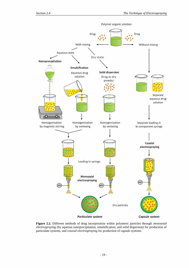
Several methods can be employed for the encapsulation of biomolecules (also
referred as drugs) into electrosprayed polymeric particles, as shown in Figure 2.2.
The resultant particles may be categorised into two distinct groups:
- particulate systems, where the drug is intimately distributed within the polymer
structure;
- capsules, where the shell is made of the polymer while the aqueous drug solution
is located in the core.
Capsules may be obtained by coaxial electrospraying shown in Figure 2.2, where
the aqueous core solution and organic shell solution are extruded independently
through two concentric nozzles leading to the electrospraying of particles with a
distinct core-shell structure. The bi-component syringe may be connected via tubing
to separate syringes with independent flow using two syringe pumps [28, 48].
Section 2.4 The Technique of Electrospraying
- 19 -
Figure 2.2. Different methods of drug incorporation within polymeric particles through monoaxial
electrospraying (by aqueous nanoprecipitation, emulsification, and solid dispersion) for production of
particulate systems, and coaxial electrospraying for production of capsule systems.
Chapter 2 A Literature Review on Electrospraying Applied to Tissue Engineering
- 20 -
Particulate systems may be obtained by monoaxial electrospraying where the drug
is mixed with the polymer solution before electrospraying commences, shown in
Figure 2.2. In the course of electrospraying the solvent evaporates from the droplet
and the drug remains entrapped within the polymer structure, ideally randomly
distributed. The drug can be mixed in its solid state, where it is directly dispersed in
the polymer solution and vortexed before electrospraying. The drug may also be
dissolved in an aqueous solution before mixing with the polymer solution, by
emulsification or nanoprecipitation as shown in Figure 2.2. Emulsions are widely
used in traditional encapsulation methods with the water-in-oil-in-water (w/o/w)
double emulsion being the most common used, since it provides access to a wide
range of particle sizes by adjusting the conditions of the process. For electrospraying,
a single water-in-oil emulsion (w/o) may be performed where hydrophilic molecules
are first dissolved in water before encapsulation. Different surfactants may be added
to tailor the encapsulation efficiency (EE) and release profiles [71]. However, the
interface between the organic and aqueous phases may result in protein denaturation
and aggregation, which is the main drawback of all emulsion-based methods [35,
77]. Nanoprecipitation, on the other hand, avoids the denaturation problem since
high shearing rates and interfaces are absent. However it can lead to agglomeration
and is not suitable for hydrophilic biomolecules due to leakage in the aqueous phase
[40]. Solid dispersion may thus remain the most attractive option in monoaxial
electrospraying, with no or limited denaturation and high versatility of drugs that
may be incorporated (both hydrophilic and hydrophobic, small molecule and protein
drug types).
Advantages of coaxial electrospraying include high drug encapsulation
efficiencies within the capsules and the assurance that the drug has minimum contact
with the organic solvent from the polymer solution, meaning less risk of drug
degradation. Nevertheless, the biomolecules remain in aqueous solution within the
capsules before delivery, which happen when the shell starts to degrade and channels
open for release. This is an issue since the stability of some biomolecules in the
aqueous state is known to be lower compared to the dry state, which may
consequently result in loss of bioactivity [71]. Nevertheless coaxial electrospraying
supposedly allows better control over release kinetics due to an increased number of
variable parameters [48, 80, 81].
Section 2.5 Control of Particle Characteristics with Electrospraying Parameters
- 21 -
More complex devices such as tri-needle coaxial devices can allow for more drugs
to be loaded within separated layers of the capsule for sequential and multiple release
[79, 82]. This can also be achieved with normal coaxial electrospraying with loading
of a second drug in the polymer core. However it was previously shown that the
polarity of the drug is of importance and capsules that contain a hydrophobic drug in
the core and a hydrophilic drug in the shell can easily be made, whereas the opposite
configuration is more difficult to achieve [58].
2.5 CONTROL OF PARTICLE CHARACTERISTICS WITH
ELECTROSPRAYING PARAMETERS
2.5.1 Importance of Electrospraying Parameters
Although electrospraying is accepted as a technique which can produce particles with
monodisperse size distributions and reproducible morphologies by controlling the
electrospraying parameters [49, 83], producing particles with very specific
requirements remains challenging due to the large number of variables involved in
the process and their complex inter-dependence. The primary pre-requisite for
reproducible electrospraying and monodisperse size production is the stable cone-jet
mode, for which the working window can be found by tailoring the field strength,
conductivity and flow rate of the polymer solution. Morphology and size can be
further controlled by adjusting additional parameters, such as the polymer
concentration and molecular weight, the solvent vapour pressure, the flow rate, the
electrospraying distance and chamber environment.
2.5.1.1 Polymers
2.5.1.1.1 Polymer Types
Currently, the most common synthetic biodegradable polymer used in the field of
drug delivery and also most commonly used in electrospraying is poly(lactic-co-
glycolic acid). This aliphatic polyester is approved by the American Food and Drug
Administration (FDA) and it is widely used in several medical devices (sutures,
grafts, prostheses) and drug delivery devices [7]. PLGA degrades mainly through
hydrolysis, which distinguishes it from natural biodegradable materials such as fibrin
and collagen which are actively degraded enzymatically in the presence of cells. The
natural products arising from degradation (lactic and glycolic acid) are then cleared
Chapter 2 A Literature Review on Electrospraying Applied to Tissue Engineering
- 22 -
by metabolic pathways [84]. In contrast, the degradation of PLGA via hydrolysis
results in the generation of acidic species which can provoke inflammation of tissues
and generate problems for long-term stability when encapsulating bioactive
molecules. For instance, in vitro simulations of the polymer microclimate of PLGA
microparticles produced using traditional methods revealed a highly acidic
environment (pH < 3), further triggering unfolding of encapsulated serum albumin
(SA), resulting in peptide bond hydrolysis and non-covalent aggregation [85]. Anti-
acid excipients such as magnesium carbonate (MgCO3) or magnesium hydroxide
(Mg(OH)2) can be used in the microparticle fabrication process to buffer the pH [86].
SA structural losses and aggregation were indeed prevented for over one month with
Mg(OH)2 from PLGA microparticles and this strategy was further employed for
delivering angiogenic basic fibroblast GF and bone-regenerating morphogenetic
protein-2 [85]. However no studies so far have tested these anti-acids in
electrosprayed particles, where microclimate pH was mentioned but not addressed
[71], although PLGA remains the most utilised polymer for electrosprayed particles
[52-59, 71].
Polylactides (PLAs) have similar properties to PLGAs but they afford a more
crystalline structure responsible for a slower degradation [58]. Select studies have
chosen pure PLAs over the PLGA copolymers for monoaxially electrosprayed
particles [60, 64, 73, 74], or simultaneously in coaxial electrospraying with PLA as
the core and PLGA as the shell to ensure that the drug in the core was not released
prematurely by choosing a core of slower degrading material than the shell [58, 87].
Very different molecular weights (MW), such as 2 kDa [64] and 175 kDa [73], have
been chosen when electrospraying PLAs. MW has a great influence on degradation
and thus subsequent release of encapsulated biomolecules; PLA 2 kDa degrades
quicker in vivo and is more soluble than higher MW PLAs [64].
The biodegradable polyester polycaprolactone (PCL) is an interesting candidate
for drug delivery and has also been used in electrospraying [55, 59, 66, 68, 71].
Compared to PLGA and PLA, PCL is semi-crystalline with a melting temperature of
approximately 60°C and a glass transition temperature around -60°C (compared to
40 to 65°C for PLGA/PLA) conferring superior viscoelastic properties and easy
formability [88, 89]. PCL is also FDA-approved and various drugs have been
encapsulated in PCL microspheres and nanospheres since PCL is highly permeable
to small drug molecules. Due to its crystallinity and lower ester concentration, PCL
Section 2.5 Control of Particle Characteristics with Electrospraying Parameters
- 23 -
presents the advantage of a less acidic environment being generated during
degradation as compared to PLGA-based polymers [68, 90]. Nevertheless, the high
hydrophobicity of PCL remains a concern for encapsulation of hydrophilic
substances such as peptides, enzymes and other proteins [18].
Although all the aforementioned biodegradable polyesters, PLGA, PLA and PCL,
have generated considerable interest in the last decades as potential matrices for drug
delivery, overall concerns remain, particularly with regard to slow degradation and
hydrophobicity (in the case of PCL) and acidic environment generation (in the case
of PLGA and PLA) leading to possible instability, aggregation and structural
changes of the loaded drug/protein. The introduction of functional groups can
provide these polymers with tunable crystallinity and enhanced hydrophilicity. The
description of such functional polymers and use so far in the field of drug delivery
has been recently summarised in the review by the group of Hennink [91].
An elegant approach to improve the utility of PCL is to copolymerise with a more
hydrophilic commoner. For example, PCL has been functionalised with hydrophilic
components such as polyamino ethyl ethylene phosphate (PPE-EA), in order to
improve hydrophobicity. The amphiphilic block copolymer, PCL-PPE-EA, was
indeed shown to encapsulate SA more efficiently than PCL alone [92]. During the
w/o emulsion procedure, when the protein is introduced into the polymer solution,
micelles are formed around the protein with the hydrophilic part of the polymer
(PPE-EA) in contact with the protein. Such micelle-derived electrosprayed particles
encapsulating SA were 3 µm in diameter and exhibited a linear release profile for 20
days whereas no protein was released from PCL only particles. Unfortunately, the
formulation and processing parameters of PCL particles loaded with SA were not
described in the study and the release data was not normalised to the amount of
loaded protein, rendering the assessment of the system delicate [92].
Natural polymers have also been electrosprayed, including elastin-like
polypeptides (ELP) [61, 93], a bioresponsive biopolymer that can be dissolved in
water, an advantage compared to polyester-based polymers that require organic
solvents to dissolve them. ELP are inspired by the amino acid sequence of natural
elastin and can be synthesised by recombinant DNA methods, allowing for a control
over the ELP sequence and thus over its biofunctionality [94]. Chitosan is another
natural polymer that has been electrosprayed. Chitosan comes from the alkaline
deacetylation of chitin and its main advantage is that it is hydrophilic, which
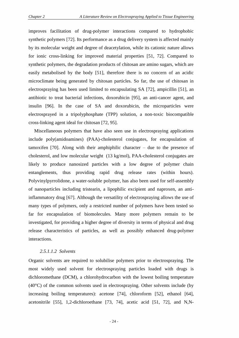
Chapter 2 A Literature Review on Electrospraying Applied to Tissue Engineering
- 24 -
improves facilitation of drug-polymer interactions compared to hydrophobic
synthetic polymers [72]. Its performance as a drug delivery system is affected mainly
by its molecular weight and degree of deacetylation, while its cationic nature allows
for ionic cross-linking for improved material properties [51, 72]. Compared to
synthetic polymers, the degradation products of chitosan are amino sugars, which are
easily metabolised by the body [51], therefore there is no concern of an acidic
microclimate being generated by chitosan particles. So far, the use of chitosan in
electrospraying has been used limited to encapsulating SA [72], ampicillin [51], an
antibiotic to treat bacterial infections, doxorubicin [95], an anti-cancer agent, and
insulin [96]. In the case of SA and doxorubicin, the microparticles were
electrosprayed in a tripolyphosphate (TPP) solution, a non-toxic biocompatible
cross-linking agent ideal for chitosan [72, 95].
Miscellaneous polymers that have also seen use in electrospraying applications
include poly(amidoamines) (PAA)-cholesterol conjugates, for encapsulation of
tamoxifen [70]. Along with their amphiphilic character – due to the presence of
cholesterol, and low molecular weight (13 kg/mol), PAA-cholesterol conjugates are
likely to produce nanosized particles with a low degree of polymer chain
entanglements, thus providing rapid drug release rates (within hours).
Polyvinylpyrrolidone, a water-soluble polymer, has also been used for self-assembly
of nanoparticles including tristearin, a lipophilic excipient and naproxen, an anti-
inflammatory drug [67]. Although the versatility of electrospraying allows the use of
many types of polymers, only a restricted number of polymers have been tested so
far for encapsulation of biomolecules. Many more polymers remain to be
investigated, for providing a higher degree of diversity in terms of physical and drug
release characteristics of particles, as well as possibly enhanced drug-polymer
interactions.
2.5.1.1.2 Solvents
Organic solvents are required to solubilise polymers prior to electrospraying. The
most widely used solvent for electrospraying particles loaded with drugs is
dichloromethane (DCM), a chlorohydrocarbon with the lowest boiling temperature
(40°C) of the common solvents used in electrospraying. Other solvents include (by
increasing boiling temperatures): acetone [74], chloroform [52], ethanol [64],
acetonitrile [55], 1,2-dichloroethane [73, 74], acetic acid [51, 72], and N,N-
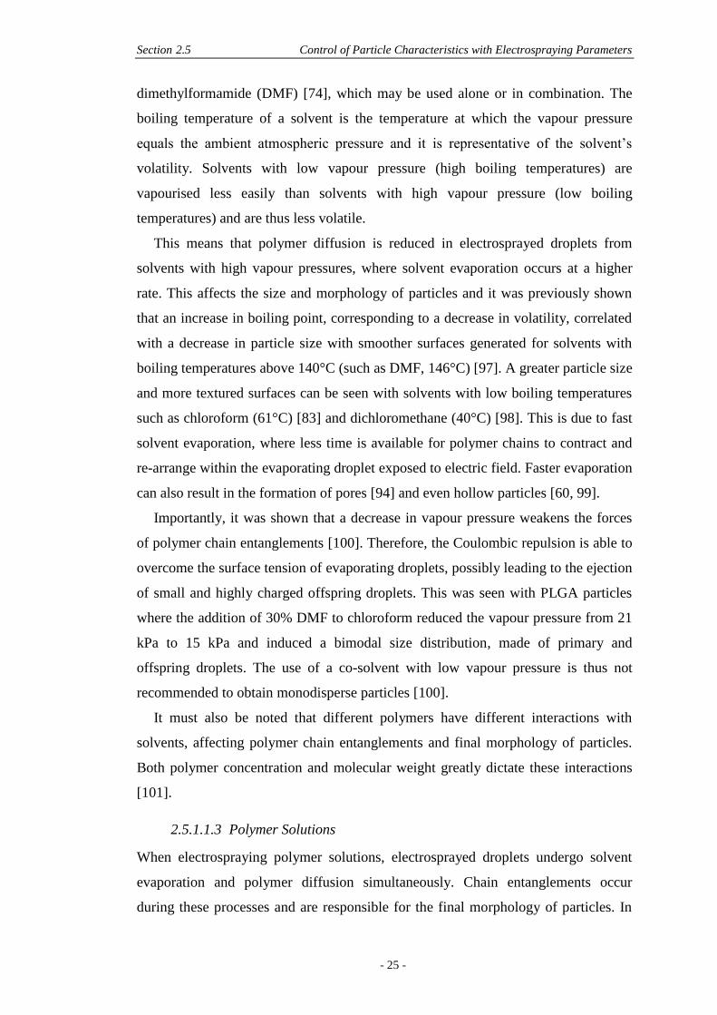
Section 2.5 Control of Particle Characteristics with Electrospraying Parameters
- 25 -
dimethylformamide (DMF) [74], which may be used alone or in combination. The
boiling temperature of a solvent is the temperature at which the vapour pressure
equals the ambient atmospheric pressure and it is representative of the solvent’s
volatility. Solvents with low vapour pressure (high boiling temperatures) are
vapourised less easily than solvents with high vapour pressure (low boiling
temperatures) and are thus less volatile.
This means that polymer diffusion is reduced in electrosprayed droplets from
solvents with high vapour pressures, where solvent evaporation occurs at a higher
rate. This affects the size and morphology of particles and it was previously shown
that an increase in boiling point, corresponding to a decrease in volatility, correlated
with a decrease in particle size with smoother surfaces generated for solvents with
boiling temperatures above 140°C (such as DMF, 146°C) [97]. A greater particle size
and more textured surfaces can be seen with solvents with low boiling temperatures
such as chloroform (61°C) [83] and dichloromethane (40°C) [98]. This is due to fast
solvent evaporation, where less time is available for polymer chains to contract and
re-arrange within the evaporating droplet exposed to electric field. Faster evaporation
can also result in the formation of pores [94] and even hollow particles [60, 99].
Importantly, it was shown that a decrease in vapour pressure weakens the forces
of polymer chain entanglements [100]. Therefore, the Coulombic repulsion is able to
overcome the surface tension of evaporating droplets, possibly leading to the ejection
of small and highly charged offspring droplets. This was seen with PLGA particles
where the addition of 30% DMF to chloroform reduced the vapour pressure from 21
kPa to 15 kPa and induced a bimodal size distribution, made of primary and
offspring droplets. The use of a co-solvent with low vapour pressure is thus not
recommended to obtain monodisperse particles [100].
It must also be noted that different polymers have different interactions with
solvents, affecting polymer chain entanglements and final morphology of particles.
Both polymer concentration and molecular weight greatly dictate these interactions
[101].
2.5.1.1.3 Polymer Solutions
When electrospraying polymer solutions, electrosprayed droplets undergo solvent
evaporation and polymer diffusion simultaneously. Chain entanglements occur
during these processes and are responsible for the final morphology of particles. In
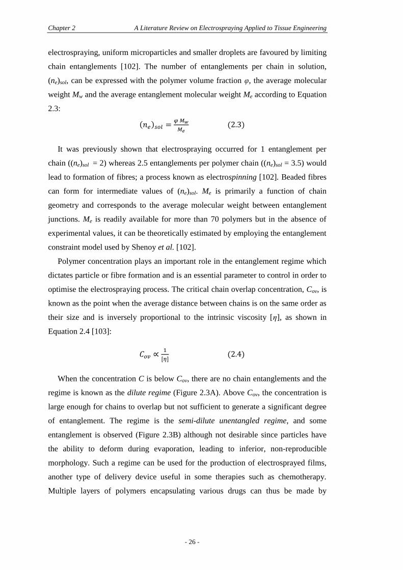
Chapter 2 A Literature Review on Electrospraying Applied to Tissue Engineering
- 26 -
electrospraying, uniform microparticles and smaller droplets are favoured by limiting
chain entanglements [102]. The number of entanglements per chain in solution,
(ne)sol, can be expressed with the polymer volume fraction φ, the average molecular
weight Mw and the average entanglement molecular weight Me according to Equation
2.3:
( )
(2.3)
It was previously shown that electrospraying occurred for 1 entanglement per
chain ((ne)sol = 2) whereas 2.5 entanglements per polymer chain ((ne)sol = 3.5) would
lead to formation of fibres; a process known as electrospinning [102]. Beaded fibres
can form for intermediate values of (ne)sol. Me is primarily a function of chain
geometry and corresponds to the average molecular weight between entanglement
junctions. Me is readily available for more than 70 polymers but in the absence of
experimental values, it can be theoretically estimated by employing the entanglement
constraint model used by Shenoy et al. [102].
Polymer concentration plays an important role in the entanglement regime which
dictates particle or fibre formation and is an essential parameter to control in order to
optimise the electrospraying process. The critical chain overlap concentration, Cov, is
known as the point when the average distance between chains is on the same order as
their size and is inversely proportional to the intrinsic viscosity [η], as shown in
Equation 2.4 [103]:
(2.4)
When the concentration C is below Cov, there are no chain entanglements and the
regime is known as the dilute regime (Figure 2.3A). Above Cov, the concentration is
large enough for chains to overlap but not sufficient to generate a significant degree
of entanglement. The regime is the semi-dilute unentangled regime, and some
entanglement is observed (Figure 2.3B) although not desirable since particles have
the ability to deform during evaporation, leading to inferior, non-reproducible
morphology. Such a regime can be used for the production of electrosprayed films,
another type of delivery device useful in some therapies such as chemotherapy.
Multiple layers of polymers encapsulating various drugs can thus be made by
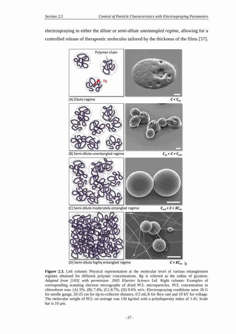
Section 2.5 Control of Particle Characteristics with Electrospraying Parameters
- 27 -
electrospraying in either the dilute or semi-dilute unentangled regime, allowing for a
controlled release of therapeutic molecules tailored by the thickness of the films [57].
b
Figure 2.3. Left column: Physical representation at the molecular level of various entanglement
regimes obtained for different polymer concentrations. Rg is referred as the radius of gyration.
Adapted from [103] with permission. 2005 Elsevier Science Ltd. Right column: Examples of
corresponding scanning electron micrographs of dried PCL microparticles. PCL concentration in
chloroform was: (A) 5%, (B) 7.4%, (C) 8.7%, (D) 9.6% wt/v. Electrospraying conditions were 26 G
for needle gauge, 20-25 cm for tip-to-collector distance, 0.5 mL/h for flow rate and 10 kV for voltage.
The molecular weight of PCL on average was 130 kg/mol with a polydispersity index of 1.45. Scale
bar is 10 µm.
Polymer chain
Rg
(A) Dilute regime C < Cov
(B) Semi-dilute unentangled regime Cov < C < Cent
(C) Semi-dilute moderately entangled regime Cent < C < 3Cov
(D) Semi-dilute highly entangled regime C > 3Cov
Chapter 2 A Literature Review on Electrospraying Applied to Tissue Engineering
- 28 -
For electrospraying of particles, the regime of choice is the semi-dilute moderately
entangled regime. It happens for Cent, the crossover from the semi-dilute unentangled
regime to the semi-dilute moderately entangled regime, where a significant degree of
entanglement is observed and dense, solid and reproducible particles can be
produced (Figure 2.3C). However, for C/Cov>3, molecular cohesion is generally too
high for electrospraying and beaded fibres or fibres are electrospun, corresponding to
the semi-dilute highly entangled regime (Figure 2.3D). For optimal particle
electrospraying, it is thus essential to work above Cent but not overcome C/Cov>3.
The molecular weight and molecular weight distribution (MWD) do affect Cov due to
differences in intrinsic viscosity, and it was demonstrated that an increase in MW
reduces the C/Cov ratio, narrowing the working window of the semi-dilute moderately
entangled regime, thus narrowing the range of appropriate concentrations for
reproducible electrospraying. On the other hand, for broader MWD, the ratio C/Cov
required to obtain the semi-dilute highly entangled regime was shown to be higher
than 3, broadening the working window of the semi-dilute moderately entangled
regime where reproducible electrospraying can be obtained [103].
2.5.1.2 Processing Parameters
2.5.1.2.1 Spraying Modes
Different spraying modes can take place in the course of electrospraying and they
vary according to the field strength and flow rate of the polymer solution. The
magnitude of the field strength is a key to reproducible spraying patterns [59] and its
variation leads to different spraying modes, starting from the dripping mode and
moving to cone-jet modes with increasing applied voltage [28]. When sufficient
voltage is applied to the droplet to form the Taylor cone (corresponding to the
change-over from dripping mode to cone-jet mode), the ejection of small and highly
charged droplets assumes the form of a cone which proportionally increases with an
increase in the tip-to-collector distance. This single cone-jet mode seen for moderate
field strengths is stable and fairly consistent from one replicate to the next [68].
Conversely, when increasing the field strengths, multiple cone-jets are formed, which
are unstable and unpredictable, and importantly can vary throughout the course of
electrospraying [59]. Such modes can be found in all types of electrospraying setups
and are also observed for the nozzle-ring setup when increasing the potential
difference between the nozzle and ring [55]. The multiple cone-jet mode needs to be
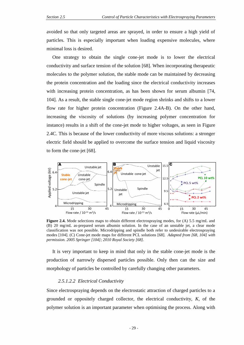
Section 2.5 Control of Particle Characteristics with Electrospraying Parameters
- 29 -
avoided so that only targeted areas are sprayed, in order to ensure a high yield of
particles. This is especially important when loading expensive molecules, where
minimal loss is desired.
One strategy to obtain the single cone-jet mode is to lower the electrical
conductivity and surface tension of the solution [68]. When incorporating therapeutic
molecules to the polymer solution, the stable mode can be maintained by decreasing
the protein concentration and the loading since the electrical conductivity increases
with increasing protein concentration, as has been shown for serum albumin [74,
104]. As a result, the stable single cone-jet mode region shrinks and shifts to a lower
flow rate for higher protein concentration (Figure 2.4A-B). On the other hand,
increasing the viscosity of solutions (by increasing polymer concentration for
instance) results in a shift of the cone-jet mode to higher voltages, as seen in Figure
2.4C. This is because of the lower conductivity of more viscous solutions: a stronger
electric field should be applied to overcome the surface tension and liquid viscosity
to form the cone-jet [68].
Figure 2.4. Mode selections maps to obtain different electrospraying modes, for (A) 5.5 mg/mL and
(B) 20 mg/mL as-prepared serum albumin solution. In the case of an unstable jet, a clear mode
classification was not possible. Microdripping and spindle both refer to undesirable electrospraying
modes [104]. (C) Cone-jet mode maps for different PCL solutions [68]. Adapted from [68, 104] with
permission. 2005 Springer [104]; 2010 Royal Society [68].
It is very important to keep in mind that only in the stable cone-jet mode is the
production of narrowly dispersed particles possible. Only then can the size and
morphology of particles be controlled by carefully changing other parameters.
2.5.1.2.2 Electrical Conductivity
Since electrospraying depends on the electrostatic attraction of charged particles to a
grounded or oppositely charged collector, the electrical conductivity, K, of the
polymer solution is an important parameter when optimising the process. Along with
Flow rate (µL/min)0 15 30 45
6.5
9.5
12.5
15.5
PCL 10 wt%
PCL 5 wt%
PCL 2 wt%
C
45
5.2
6.4
15 30Flow rate / 10-11 m3/s
Unstable jet
Unstable cone-jet
Spindle
Unstable jet
Stable cone-jet
Microdripping4
A
Ap
plie
d v
olt
age
(kV
)
15 30 45
Unstable jet
SpindleUnstable jet
Microdripping
Unstable cone-jet
Stable cone-jet
5.2
6.4
Flow rate / 10-11 m3/s
4
B
Chapter 2 A Literature Review on Electrospraying Applied to Tissue Engineering
- 30 -
flow rate, electrical conductivity provides a powerful means to control the
electrosprayed particle size, as demonstrated by the scaling laws from Gañan-Calvo,
where a higher conductivity leads to a decrease in size [105].
An increased conductivity of a solution implies that more charge is carried by the
electrospraying jet. In general, a low electrical conductivity is preferred to obtain
quasi-monodisperse particles [100] since a higher conductivity may favour elongated
particles or even fibres if the polymer concentration is high enough [106].
Correlating with viscosity, stable electrospraying is known to be achieved only when
viscosity is high or conductivity is low [107]. Changes in electrical conductivity can
be obtained by changing the electrospraying solvent or using co-solvents, although
this latter case may be detrimental to size distribution and morphology of particles
[74, 100]. Organic solvents are generally less conductive than aqueous solvents and
their conductivity can be increased by the addition of electrolytes, such
didodecyltrimethylammonium bromide (DTAB) [56] or ammonium hydroxide [64],
which can increase conductivity by orders of magnitude. For instance the
conductivity of a 5% wt/v PLGA solution in acetonitrile containing 10% wt
paclitaxel was shown to increase from 0.51 μS/cm to 116.5 μS/cm by the addition of
2 mM DTAB. This led to a particle size decrease from around 1.2 μm to 355 nm
[56]. Compared to pure solvents, it must be kept in mind that the addition of a
polymer will most likely decrease the electrical conductivity, although remaining in
the same order of magnitude [108].
When the electrical conductivity of the solution is lower than 0.01 µS/m, it is
likely that insufficient current can flow, and the liquid cannot be electrosprayed,
although too a high conductivity value leads to unstable electrospraying [59]. The
bending instability of the jet becomes more important when more charges are present
due to increased conductivity, leading to a wider deposition of particles on the
collector. With higher electrical conductivity, the Coulombic repulsion forces are
higher and compete with the viscoelastic forces of the solution, disentangling more
easily the polymer network which is being formed during electrospraying. In other
words, increasing conductivity makes it easier for the solution to be broken up into
smaller droplets. Therefore for the same polymer dissolved at the same concentration
in a higher conductive solvent (or the same solvent but supplemented with organic
salts), disentanglement may take place during electrospraying, in turn reducing the
final particle size. Furthermore, if the Coulombic repulsion forces are sufficiently
Section 2.5 Control of Particle Characteristics with Electrospraying Parameters
- 31 -
high to overcome the entanglement forces, then Coulomb fission occurs before
strong entanglements can form, and smaller offsprings are ejected from the primary
droplet. This will provide a bimodal size distribution, with particles presenting
various types of morphologies, mostly unwanted and further discussed in the section
2.5.2. Low electrical conductivity may thus be more favourable for electrospraying
of quasi-monodispere microparticles.
When nanoparticles are required, increasing conductivity may be a good means of
reducing particle size, although sufficient viscosity needs to be ensured so that
entanglement forces remain higher than Coulomb forces, and the ejection of
offspring droplets is avoided. Higher flow rates can also be used to produce
nanoparticles – if higher salt concentration is used to increase solution conductivity
[56]. In the context of electrospraying emulsions, the organic/aqueous volume ratio is
another significant factor influencing the electrical conductivity whereby addition of
water to the organic phase significantly increases the electrical conductivity of the
resulting emulsions [73].
2.5.1.2.3 Flow Rate
After the selection of polymer solutions, flow rate is arguably the second most
important parameter in electrospraying and together with the solution parameters
(polymer MW, concentration, solvent, and conductivity) can control polymer
entanglements and Coulomb fission [49]. Flow rate thus has consequences for both
the morphology and size of particles and must be judiciously chosen since both these
characteristics will influence the drug dispersion within the polymer matrix,
ultimately affecting drug release.
Firstly, it is essential to use a flow rate that allows for complete solvent
evaporation, which is not possible with high flow rates. Particles are partially
solvated when they impact the collector leading to a deformed and non-consistent
morphology [55, 83]. Furthermore, too high flow rates can confer a bimodal or
polydisperse character to the size of electrosprayed particles. This is explained by the
processes involved in solvent evaporation from the charged droplet, based on φRay,
the polymer volume fraction in a droplet at the Rayleigh limit, and expressed in
Equation 2.5:
(
)
(2.5)

Chapter 2 A Literature Review on Electrospraying Applied to Tissue Engineering
- 32 -
where Q is the liquid flow rate (m3/s), I the current, εair the permittivity of air, γ the
surface tension of solution in ambient air, and d the initial droplet diameter. I/Q and d
can be determined as a function of Q and the polymer solution properties.
Considering φent as the critical entanglement polymer volume fraction and φov as
the critical chain overlap polymer volume fraction, it was shown by Almería et al.
that for φov < φRay < φent in the semi-dilute unentangled regime mentioned previously,
the polymer network can preserve some droplet integrity, but is not strong enough to
preserve the particle from deforming via stretching during the fission process, while
droplets are stabilised from such rupture when φRay > φent [49]. For φRay < φov, the
droplets behave like a pure liquid and there are no entanglements, leading to the
ejection of offspring droplets from the primary droplet, a consequence of Coulomb
fission. In order to obtain a spherical morphology and monodispersity, it is important
that sufficient entanglements are present before the Rayleigh limit is reached so that
the droplet cannot be disrupted by Coulomb fission, ensuring that φRay > φent.
According to Equation 2.5, flow rate has a significant influence on φRay and it was
shown for the morphology of PLGA particles that larger flow rates decreased φRay,
generating non-spherical morphology with the possible formation of offspring
droplets and extruded fibres when concentration was sufficiently high [49].
In addition to offspring droplets that can form, high flow rates can also generate
secondary droplets, even in an entangled network, due to the perturbation amplitude
of the electrospraying jet, which is increased with increased flow rates [100]. This
can be explained by the phenomena occurring when the droplets are ejected from the
Taylor cone. Initially, a filament unites 2 droplets, but it is further broken up by the
charge. Once broken from the farthest droplet, the filament flows back to the nearest
droplet from the cone, and monodisperse particles can be achieved, for relatively low
flow rates. At increased rates, there is more distance between evaporating droplets.
Thus the filament may not reach the former droplet anymore and instead it breaks,
forming a secondary smaller droplet. At even higher flow rates, a filament between
primary and secondary can form, which, being unable to reach back to the primary
droplet, turns into a satellite droplet (even smaller than secondary droplets) [42]. If
the solvent has a high evaporation rate, it is even possible that the filament remains
frozen, leading not only to polydisperse sizes but also leading to elongated particles
[49].
Section 2.5 Control of Particle Characteristics with Electrospraying Parameters
- 33 -
The same rules apply for coaxial electrospraying where the inner and outer flow
rates may strongly affect the properties of electrosprayed capsules. Usually the flow
rate of the core solution is much lower than the shell solution [77], resulting in
uniform sizes. In contrast, for a shell flow rate slower or equal to that of the core
flow rate, irregular morphologies are obtained, while for increasing ratios of
shell:core flow rates, the shell becomes thicker [80]. This presents a useful tool for
the tailoring of release kinetics.
2.5.1.2.4 Other Parameters
Effect of Gauge
The diameter of a needle is commonly expressed in gauge (G), each gauge size
arbitrarily correlating to multiples of 0.001 inches [109]. For the electrospraying of
particles loaded with bioactive molecules, these diameters range from 18 G (internal
diameter (ID) of 1.27 mm) [73, 74] to 29 G (ID of 0.33 mm) [56]. Prior to
electrospraying, beveled needles are typically shortened and given a flat end for
homogeneous spraying, although characterisation of the needle tip, while important,
is often overlooked. The effect of gauge has little effect on morphology or size of
particles. For instance when comparing the size of PCL particles made with 21 G
versus 26 G, the average size was equivalent for both gauges, however the size
distribution was slightly broader for the bigger gauge (21 G) with standard deviation
(SD) of 3.42 while SD was 2.40 for 26 G, suggesting that a smaller gauge can
produce a narrower size distribution [83]. A similar result was observed in the 20 to
26 G range when electrospraying ampicillin-loaded chitosan nanoparticles, where the
use of the 20 G led to sputtering only, 22 G led to a mixture of particles and
sputtering, while 24 and 26 G led to spherical particles with no sputtering and with
reduced polydispersity for the smallest gauge (26 G) [51].
Effect of Voltage
The main incidence of voltage is on spraying modes as described previously in
section 2.5.1.2.1. Within the single cone-jet mode, size is not significantly affected
by voltage where only a slight decrease in size is observed when voltage is increased
[52]. Morphology however will be changed as stated by Shenoy et al., since as the
voltage is increased, the morphology changes from spherical particles to elongated
particles or beaded fibres to eventually only fibres if concentration is sufficiently
high [102]. This is due to more charge acting on droplets with increased voltage,
Chapter 2 A Literature Review on Electrospraying Applied to Tissue Engineering
- 34 -
leading to stretching and elongation of droplets. It is therefore recommended to use
moderate voltages that allow for the single cone-jet mode to take place while
maintaining the spherical morphology of particles.
Effect of Tip-To-Collector (TTC) Distance
The lower limit of distance is determined by electric discharge. A small TTC
distance can impair full solvent evaporation and consequently, wet microspheres
impact the collector, leading to collapsing, coalescence and broad size distributions
[51]. Increasing the distance leads to more spherical morphologies since polymer
chains have sufficient time to diffuse within the droplet [83] and thus also reduced
polydispersity. At constant voltage, a decrease in the TTC distance leads to an
increase in the strength of the electric field, thus leading to a decrease in particle size
[108]. Depending on the type of solvent used, an increase in TTC distance may also
be detrimental for morphology as shown with polyacrylonitrile microspheres in DMF
where at 10 cm, the evaporation rate of DMF allowed round spheres to be formed,
while at 20 cm, the round spheres collapsed into half-hollow spheres. The authors
stated that the evaporation rate was excessive. However this result was not clearly
evident in the images shown by the authors, and no explanation was proposed [110].
2.5.2 Tailoring of Electrosprayed Particle Characteristics
2.5.2.1 Morphology
The morphology of electrosprayed particles is controlled by solvent evaporation and
polymer diffusion [49]. The polymer solution thus plays a determinant role in these
mechanisms, where the nature of polymer (solubility, molecular weight,
concentration) and solvent (vapour pressure, miscibility, conductivity of solution)
coupled with the solution flow rate form the levers of morphology tailoring [83]. As
explained previously in the section 2.5.1.1.3, regarding polymer solutions,
concentration and molecular weight can dictate the entanglement regime taking
place, leading to reproducible and solid electrosprayed particles, when a certain
degree of chain entanglement is obtained. Therefore in most studies, morphology is
initially linked to polymer concentration and molecular weight, where a decrease in
concentration or an increase in molecular weight induces non-spherical morphologies
such as shell-like, wrinkled, hollow particles, beaded fibres or particles with tails
(Figure 2.5A-B). However, as seen in the section 2.5.1.2.3, flow rate also has a
significant influence on morphology through φRay, the polymer volume fraction in a
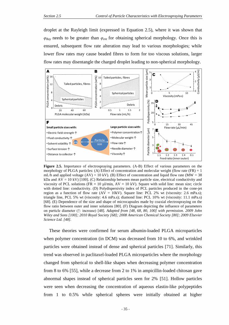
Section 2.5 Control of Particle Characteristics with Electrospraying Parameters
- 35 -
droplet at the Rayleigh limit (expressed in Equation 2.5), where it was shown that
φRay needs to be greater than φent for obtaining spherical morphology. Once this is
ensured, subsequent flow rate alteration may lead to various morphologies; while
lower flow rates may cause beaded fibres to form for too viscous solutions, larger
flow rates may disentangle the charged droplet leading to non-spherical morphology.
Figure 2.5. Importance of electrospraying parameters. (A-B) Effect of various parameters on the
morphology of PLGA particles: (A) Effect of concentration and molecular weight (flow rate (FR) = 1
mL/h and applied voltage (AV) = 10 kV). (B) Effect of concentration and liquid flow rate (MW = 38
kDa and AV = 10 kV) [100]. (C) Relationship between mean particle size, electrical conductivity and
viscosity of PCL solutions (FR = 10 µl/min, AV = 10 kV). Square with solid line: mean size; circle
with dotted line: conductivity. (D) Polydispersivity index of PCL particles produced in the cone-jet
region as a function of flow rate (AV = 10kV). Square line: PCL 2% wt (viscosity: 2.6 mPa.s);
triangle line, PCL 5% wt (viscosity: 4.6 mPa.s); diamond line: PCL 10% wt (viscosity: 11.1 mPa.s)
[68]. (E) Dependence of the size and shape of microcapsules made by coaxial electrospraying on the
flow ratio between outer and inner solutions [80]. (F) Diagram depicting the influence of parameters
on particle diameter (↑: increase) [48]. Adapted from [48, 68, 80, 100] with permission. 2009 John
Wiley and Sons [100]; 2010 Royal Society [68]; 2008 American Chemical Society [80]; 2009 Elsevier
Science Ltd. [48].
These theories were confirmed for serum albumin-loaded PLGA microparticles
when polymer concentration (in DCM) was decreased from 10 to 6%, and wrinkled
particles were obtained instead of dense and spherical particles [71]. Similarly, this
trend was observed in paclitaxel-loaded PLGA microparticles where the morphology
changed from spherical to shell-like shapes when decreasing polymer concentration
from 8 to 6% [55], while a decrease from 2 to 1% in ampicillin-loaded chitosan gave
abnormal shapes instead of spherical particles seen for 2% [51]. Hollow particles
were seen when decreasing the concentration of aqueous elastin-like polypeptides
from 1 to 0.5% while spherical spheres were initially obtained at higher
Tailed particles, fibres
Spherical particles
Debris2
4
6
8
0
10
PLG
A c
on
cen
trat
ion
(wt%
)
0.5 1 1.5 2
Flow rate (mL/h)
Particle size
Small particle sizes with:
•Electric field strength ↑
•Fluid conductivity ↑
•Solvent volatility ↑
•Surface tension ↑
•Distance to collector ↑
Large particle sizes with:
•Polymer concentration↑
•Molecular weight ↑
•Flow rate↑
•Needle diameter ↑
•Viscosity↑
A B
F
Me
an p
arti
cle
siz
e (µ
m)
Viscosity (mPa s)
3
1
5
0 5 10 Co
nd
uct
ivit
y (µ
S/m
)
2
0
4
C
PLG
A c
on
cen
trat
ion
(wt%
)
4
8
12
16
020 40 60
Tailed particles, fibres
Spherical particles
Debris
PLGA molecular weight (kDa)
5
3
1
7
Par
ticl
e d
iam
ete
r (µ
m)
0:1
Feed ratio (inner:outer)1:1 1:2 1:3 1:4
E
Po
lyd
isp
ers
ivit
y (%
)
20
5
35
Flow rate (µL/min)0 15 4530
D

Chapter 2 A Literature Review on Electrospraying Applied to Tissue Engineering
- 36 -
concentrations [61]. The effect of polymer concentration was also considered with
MW where a higher MW (70,200 g/mol versus 17,800 g/mol) provided tailed
structures or beaded fibres instead of spherical particles for both concentrations [61].
As explained previously, this is a consequence of high viscosity with stronger
entanglements taking place for high MW polymer chains, impairing full jet break-up.
In coaxial electrospraying, flow rates of both core and shell solutions are
determinant for reproducible morphology and size of capsules, where inner flow
rates are required to be lower than outer flow rates. Decreasing the inner flow rates
led to a thicker capsule shell and reduced particle size (Figure 2.5E) [80]. When
loading paclitaxel and suramin in the PLGA shell and poly-L-lactide (PLLA) core of
microcapsules, respectively, it was concluded that a Qcore ranging between 1.0 and
2.0 mL/h and a constant Qshell of 2.0 mL/h may maintain a stable cone-spraying mode
and consequently result in uniform and smooth microspheres with varied core sizes
[58, 87].
In electrospraying of emulsions, a decrease in the organic/aqueous phase volume
ratio (from 20:1 to 6.7:1) led to a degeneration of the spherical shape of particles
with a more wrinkled surface. This was tentatively explained by a corresponding
decrease in viscosity which would hinder the shrinkage of droplets during
evaporation [73].
Similarly, loading of biomolecules into the particles affects the morphology and
wrinkled particles were observed for a 30% - and above - loading of rifampicin in
PLGA particles [52]. This is a consequence of the difference in molecule types:
PLGA is a linear macromolecule whereas rifampicin is a small organic molecule. It
was stated that the addition of rifampicin decreased the diffusion coefficient of
solutes and weakened the intermolecular entanglements of PLGA. When the
concentration of the drug is higher than a critical value, diffusion is slower than
solvent evaporation, resulting in the increase of drug concentration near the front of
the droplets. Drug molecules accumulate and form a layer of semi-solidified skin on
the surface. With further evaporation of solvent, the intermolecular polymer
entanglements in the droplet skin predominate, forcing the semi-solidified skin to
collapse, leading to wrinkles [52].
Section 2.5 Control of Particle Characteristics with Electrospraying Parameters
- 37 -
2.5.2.2 Size
The size of polymeric particles that contain bioactive molecules significantly
influences their therapeutic capabilities. For instance, the release rate increases with a
larger surface to volume ratio of the particles [56] and is dependent on surface
diffusion and degradation. Control of size is therefore essential for tailoring release
properties. The electrospraying technique can produce particles with sizes varying
from tens of micrometers to tens of nanometres [63] and by choosing the right
parameters, low polydispersity can be obtained with relative standard deviations
(RSD) within 2 to 27% of the average size [62, 71]. This is advantageous in drug
delivery since drug distribution within the matrix can be controlled more precisely
with a single known particle size, allowing degradation rates and diffusion of drugs
to be better tailored to fit a desired application [44]. However, this is a constant issue
when microparticles are made from double emulsion fabrication methods where
broad distributions are obtained, ranging from 49 to 110% RSD [50, 64].
When nanoparticles are considered, the control of size and polydispersity
becomes even more important since they can greatly affect cell response mechanisms
where particles are internalised by cells. This involves particles lower than 500 nm
for uptake by epithelia cells for example [46], and lower than 100 nm for
applications such as tumour targeting by the enhanced permeability and retention
(EPR) effect. However, although the electrospraying technique allows the generation
of nanoparticles such as pharmaceutical nanoparticles or non-organic nanoparticles
(for coating for instance), when polymeric carriers were used to encapsulate drugs,
the resulting electrosprayed particles were mainly found to be on the micron to
submicron size. The minimum size reported so far is 116.1 nm with budesonide-
loaded PCL particles [66] and very few studies are found in the 100 to 500 nm range
[56, 61, 64, 70, 95]. This is likely due to polymer chains used in electrospraying of
polymers with drugs since a significant molecular weight and polymer concentration
are needed in order to efficiently encapsulate a drug within the polymeric matrix.
The nanosize of electrosprayed polymer/drug systems is thus less likely and most
systems actually produce micrometric sizes as seen in Table 2.1.
.
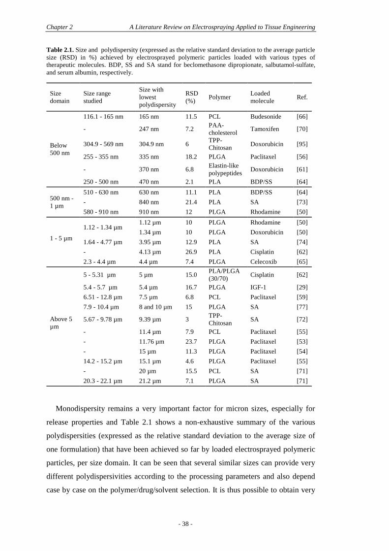
Chapter 2 A Literature Review on Electrospraying Applied to Tissue Engineering
- 38 -
Table 2.1. Size and polydispersity (expressed as the relative standard deviation to the average particle
size (RSD) in %) achieved by electrosprayed polymeric particles loaded with various types of
therapeutic molecules. BDP, SS and SA stand for beclomethasone dipropionate, salbutamol-sulfate,
and serum albumin, respectively.
Size
domain
Size range
studied
Size with
lowest
polydispersity
RSD
(%) Polymer
Loaded
molecule Ref.
Below
500 nm
116.1 - 165 nm 165 nm 11.5 PCL Budesonide [66]
- 247 nm 7.2 PAA-
cholesterol Tamoxifen [70]
304.9 - 569 nm 304.9 nm 6 TPP-
Chitosan Doxorubicin [95]
255 - 355 nm 335 nm 18.2 PLGA Paclitaxel [56]
- 370 nm 6.8 Elastin-like
polypeptides Doxorubicin [61]
250 - 500 nm 470 nm 2.1 PLA BDP/SS [64]
500 nm -
1 µm
510 - 630 nm 630 nm 11.1 PLA BDP/SS [64]
- 840 nm 21.4 PLA SA [73]
580 - 910 nm 910 nm 12 PLGA Rhodamine [50]
1 - 5 µm
1.12 - 1.34 µm 1.12 µm 10 PLGA Rhodamine [50]
1.34 µm 10 PLGA Doxorubicin [50]
1.64 - 4.77 µm 3.95 µm 12.9 PLA SA [74]
- 4.13 µm 26.9 PLA Cisplatin [62]
2.3 - 4.4 µm 4.4 µm 7.4 PLGA Celecoxib [65]
Above 5
µm
5 - 5.31 µm 5 µm 15.0 PLA/PLGA
(30/70) Cisplatin [62]
5.4 - 5.7 µm 5.4 µm 16.7 PLGA IGF-1 [29]
6.51 - 12.8 µm 7.5 µm 6.8 PCL Paclitaxel [59]
7.9 - 10.4 µm 8 and 10 µm 15 PLGA SA [77]
5.67 - 9.78 µm 9.39 µm 3 TPP-
Chitosan SA [72]
- 11.4 µm 7.9 PCL Paclitaxel [55]
- 11.76 µm 23.7 PLGA Paclitaxel [53]
- 15 µm 11.3 PLGA Paclitaxel [54]
14.2 - 15.2 µm 15.1 µm 4.6 PLGA Paclitaxel [55]
- 20 µm 15.5 PCL SA [71]
20.3 - 22.1 µm 21.2 µm 7.1 PLGA SA [71]
Monodispersity remains a very important factor for micron sizes, especially for
release properties and Table 2.1 shows a non-exhaustive summary of the various
polydispersities (expressed as the relative standard deviation to the average size of
one formulation) that have been achieved so far by loaded electrosprayed polymeric
particles, per size domain. It can be seen that several similar sizes can provide very
different polydispersivities according to the processing parameters and also depend
case by case on the polymer/drug/solvent selection. It is thus possible to obtain very
Section 2.5 Control of Particle Characteristics with Electrospraying Parameters
- 39 -
low polydispersivity with electrospraying (as low as 2.1% [64, 71]), by tailoring
electrospraying parameters, but this is a complex undertaking. Monodispersity is
obtained with reduced flow rates, increased polymer concentrations (higher
viscosities), reduced conductivity of the electrosprayed solutions and reduced applied
voltages [68, 111]. This applies for the stable-cone jet mode, known to be the only
one able to produce monodisperse particles, and when parameters such as flow rate
are used in the central cone-jet region. Indeed, when flow rate is used close to the
upper and lower limit of the cone-jet region, the polydispersivity index of particles
increases, as seen in Figure 2.5D [68].
The size of electrosprayed polymer particles is greatly influenced by flow rate and
polymer concentration, where increased particle sizes are most significantly obtained
with an increase in flow rate and polymer concentration and a decrease in
conductivity (Figure 2.5C) [83]. However, at increasing flow rates, the size
distribution also becomes broader [63] and formation of secondary droplets can take
place. This leads to a bimodal size distribution which is quite common in
electrospraying and sometimes unavoidable [28, 52, 59, 83]. Some strategies have
been suggested to separate the two size populations by using a steel plate with a 3 cm
circular hole as the grounded electrode, which serves to collect only the primary
droplet population. Often a spatial separation occurs after the droplet break-up where
two regions of electrospray can be seen during the stable cone-jet mode, since
secondary droplets have a larger surface charge density but less mass than primary
droplets. Therefore primary droplets can be found in the inner core of the
electrospraying cone, while secondary droplets get ejected at the periphery of the
cone [52]. By using a plate with a circular hole as a screen on top of the collector,
secondary droplets thus are left behind and only primary droplets are recovered
ensuring monodispersity, although reduced yield may be of concern. Hartman et al.
measured very small currents (31-57 nA) during electrospraying and found that
another way to reduce the frequency of secondary droplets is to lower the current by
lowering the applied voltage or flow rate [42]. However secondary droplets remain
difficult to eliminate completely [52].
These findings are explained by the relationship between size and electrospraying
variables depicted by Hartman et al. in the stable single cone-jet mode and shown in
Equations 2.6 and 2.7 [42]. The droplet diameter, d, can be modeled using various
equations generated by De La Mora and Loscertales [112] in 1994, Gañan-Calvo et
Chapter 2 A Literature Review on Electrospraying Applied to Tissue Engineering
- 40 -
al. in 1997 [105] and Hartmann in 2000 [42] (Equations 2.6 and 2.7) for the single
cone-jet mode. They are functions of the liquid flow rate, Q, the solution density, ρ,
the current, I, the surface tension in ambient air, γ, and the liquid conductivity, K (α
is a constant):
(
)
(2.6)
( )
(2.7)
Particle size is directly proportional to droplet size, where an increase in particle
size is obtained with increasing flow rate and decreasing surface tension, and is
shown to correspond to an increase in polymer content [110]. However, as stated
earlier, an increase in flow rate is also responsible for broader size distributions [63],
thus a compromise needs to be made between particle size and dispersity. This is
explained in section 2.5.1.2.3, where higher flow rates lead to smaller φRay,
eventually falling in the case where φov < φRay < φent where polymer entanglements
are not strong enough to preserve the droplet integrity during electrospraying,
leading to the ejection of offspring droplets (which are around one fifth of the
primary droplets in size [100]). The first pre-requisite of monodispersity of
electrosprayed particles is thus the use of a flow rate that ensures φRay > φent, where
primary droplets cannot be disrupted by Coulomb fission. As stated by Almeria et
al., if increasing particle size is highly desired, while maintaining monodispersity,
increased flow rates could be coupled with higher polymer concentrations so that the
φRay > φent is still validated [49]. However, the use of a higher flow rate may still lead
to the formation of secondary droplets (one fifth to half of the primary droplets in
size [100]) due to increased jet perturbation, in turn providing a bimodal size
distribution.
When involving the polymer concentration parameter, particle size has been
shown to increase compared to the theoretical calculations for PLGA microparticles
containing paclitaxel made from low polymer concentrations (4, 6 and 8% in
acetonitrile), while it was in good agreement for 10%. This was attributed to the non-
spherical shape and high porosity of particles made from lower concentrations [56].
The increase in particle size as a function of the square root of flow rate was also
shown to be sharper for higher polymer concentrations. An increase in concentration
Section 2.5 Control of Particle Characteristics with Electrospraying Parameters
- 41 -
from 5% to 10% PCL in DCM, however, led only to a slight increase in size, for
paclitaxel-loaded particles from around 9 to 13 µm [59], suggesting that flow rate is
more determinant than polymer concentration for directing the size of loaded
particles. Indeed, increasing the flow rate from 4 to 8 mL/h when electrospraying
chitosan solutions significantly increased the size of microparticles at each chitosan
concentration [72]. However the size did not increase significantly with an increase
in concentration from 1 to 2%. In a similar study, an increase in polymer
concentration from 4 to 8% (PLGA 50:50 in acetonitrile) resulted in a limited change
in the particle size while for 10%, the sizes were considerably larger. This was
explained by the low diffusion rate of PLGA chains where a shell of solid PLGA
would form on the surface of the droplets. For lower polymer concentrations in the 4-
8% range, the shell would be thinner but a similar overall size would be obtained,
while for concentrations higher than 8% a high polymer concentration was
established on the surface of the droplet with less solvent evaporation, resulting in a
larger final particle size [56]. All these results underline the strong effect and inter-
dependence of flow rate coupled with concentration on particle size.
Drug loading was also shown to affect microparticle size; loading up to 15.8% of
the anti-cancer drug paclitaxel increased PLGA particle size from around 13 to 15
µm although the number of particles analysed (n) or the technique for size
measurement was not described in the study [55]. The link between loading and size
is however less evident than previous variables. In the case of electrospraying of
emulsions, the size was shown to first decrease and then increase, for a serum
albumin emulsion, when the SA:PLA weight ratio decreased from 1:2 to 1:6. This
was tentatively explained by a decrease in viscosity from less solid mass in the
emulsion causing the initial decrease in size, and the lower conductivity causing the
subsequent increase [73].
As explained in section 2.5.1.2.2, the electrical conductivity is indeed a potent
parameter for controlling particle size where the scaling laws from Gañan-Calvo
showed that a decrease in particle size can be obtained with an increase in
conductivity, according to Equation 2.8 [105]:
(
)
⁄
(2.8)
Chapter 2 A Literature Review on Electrospraying Applied to Tissue Engineering
- 42 -
The use of a solvent with a higher conductivity can thus decrease particle size as
seen when comparing PLGA particles made using acetonitrile and dichloromethane
as the solvents [108] or when adding acetone to a PLA solution of 1,2-dichloroethane
(1:1) [74] where conductivity was increased from 0.058 to 0.412 µS/cm and particles
decreased in size from 4.8 to 1.6 µm. However, it was shown that the use of co-
solvent with increased conductivity broadened the size distribution with a bimodal
character and reduced the spherical morphology of PLGA particles [100] and PLA
particles [74], respectively. The use of organic salts is more effective to increase
conductivity without causing a concomitant deterioration in the initial morphology of
particles as seen with 2 mM of DTAB added to an acetonitrile solution of PLGA and
paclitaxel [56]. In this case, particle size was decreased from 1.2 µm to 355 nm.
Other possible electrolytes include ammonium hydroxide (0.02 to 0.2% (v/v)) [64].
Although conductivity is pivotal in size tailoring, it must be kept in mind that an
increase in conductivity reduces the region of the stable cone-jet mode and hence
standard deviation tends to increase, broadening the size distribution [63]. Again this
is due to a consequent decrease in φRay which may eventually be smaller than φent
where the ejection of offspring, secondary and satellite droplets from the primary
droplets is possible. Such broadening was also observed with increasing surfactant
concentration, thus conductivity of the solution, as seen for 2-16% Pluronic® F-127
in PLGA solution in acetonitrile, although it did not appreciably reduce the average
particle size [56]. However, for budesonide-loaded PCL particles, a decrease of
Tween 20® from 0.005 to 0.001% led to a decrease from 884 to 116.1 nm under
optimal electrospraying conditions [66].
Emulsions comprising organic/aqueous and protein/polymer phases also have
significant impact on particle size [73]. Particle size increased with organic/aqueous
volume phase ratio. This was due to a corresponding increase in viscosity and
decrease in electrical conductivity which makes it more difficult for the solution to
be broken up into smaller droplets in the course of electrospraying, thus increasing
particle size. Such correlation between size, viscosity and electrical conductivity was
also seen for β-oestradiol-loaded PCL particles where an increase of PCL
concentration from 2 to 10 wt% led to a change in viscosity and electrical
conductivity of the PCL solutions from 2.6 to 11 mPa.s and from 3.4 to 0.8 µS/m,
respectively. This resulted in a mean particle size increase from 0.3 to 4.5 µm [68].
Section 2.6 Electrospraying and Drug Release Characteristics
- 43 -
2.6 ELECTROSPRAYING AND DRUG RELEASE CHARACTERISTICS
2.6.1 Choice of Molecules
Most pharmaceutical drugs and proteins are expensive. For this reason the majority
of drug delivery studies are first undertaken with model drugs or model proteins, to
enable optimisation of parameters and characteristics of particles in the first instance,
before loading fragile and expensive drugs/proteins. A non-exhaustive summary of
various drugs and proteins that have been loaded so far in electrosprayed particles is
presented in Figure 2.6.
As far as proteins are concerned, serum albumin has been widely used for this
‘model’ purpose in traditional encapsulation techniques [113], and to some extent in
electrospraying [71-74, 77, 79, 92, 114]. SA is readily available and it offers high
stability and low cost, which is advantageous in the early stages of optimisation. The
molecular mass of SA is 66.4 kg/mol, which is similar in size to some growth factors
(GFs) used for tissue regeneration, providing a more suitable choice than smaller
model molecules. Serum albumins are also extensively used as an excipient, i.e. as an
inactive substance used as carrier for the molecules of interest, since they have the
ability to bind a wide variety of biological molecules, e.g. cationic, anionic,
hydrophilic, hydrophobic substances. Many drugs, such as anti-coagulants and
anesthetics, are also transported in blood while bound to albumin [104]. Serum
albumins have no adverse effect in most biochemical reactions and they have been
shown to assist decreasing the initial burst release occurring in most particulate
systems [115], and stabilise and protect the bioactivity of molecules during the harsh
conditions of encapsulation [116].
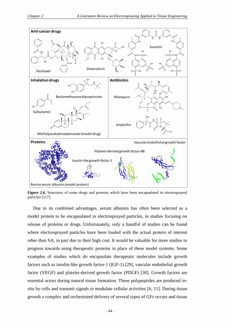
Chapter 2 A Literature Review on Electrospraying Applied to Tissue Engineering
- 44 -
Figure 2.6. Structures of some drugs and proteins which have been encapsulated in electrosprayed
particles [117].
Due to its combined advantages, serum albumin has often been selected as a
model protein to be encapsulated in electrosprayed particles, in studies focusing on
release of proteins or drugs. Unfortunately, only a handful of studies can be found
where electrosprayed particles have been loaded with the actual protein of interest
other than SA, in part due to their high cost. It would be valuable for more studies to
progress towards using therapeutic proteins in place of these model systems. Some
examples of studies which do encapsulate therapeutic molecules include growth
factors such as insulin-like growth factor-1 (IGF-1) [29], vascular endothelial growth
factor (VEGF) and platelet-derived growth factor (PDGF) [30]. Growth factors are
essential actors during natural tissue formation. These polypeptides are produced in-
situ by cells and transmit signals to modulate cellular activities [6, 11]. During tissue
growth a complex and orchestrated delivery of several types of GFs occurs and tissue
Anti-cancer drugs
PaclitaxelDoxorubicin
Suramin
Inhalation drugs
Methylparahydroxybenzoate (model drug)
Beclomethasone dipropionate
Salbutamol
Rifampicin
Antibiotics
Ampicillin
Proteins
Bovine serum albumin (model protein)
Insulin-like growth factor-1
Vascular endothelial growth factor
Platelet-derived growth factor-BB
Section 2.6 Electrospraying and Drug Release Characteristics
- 45 -
growth is dependent on this delivery. Thanks to the current technologies, GFs can
now be recombinantly produced, albeit at very high cost, and have thus attracted a lot
of interest among tissue engineers. Many drug delivery particulate systems (DDPS)
have attempted to encapsulate and release GFs in a sustained manner, mimicking the
normal in vivo production. For GFs that were encapsulated in electrosprayed
particles, we find IGF-1, PDGF and VEGF, which are mostly involved in
angiogenesis. It must be noted that their molecular mass ranges from around 7 (IGF-
1) to 45 kg/mol (VEGF) and are therefore lower than SA (66.4 kg/mol). Compared to
small drugs, proteins are also prone to denaturation, which is often an issue in DDPS
production where organic solvents are used. The technique of electrospraying
however, offers a reduced contact of proteins with solvents and most importantly
does not require the emulsion step present in the traditional fabrication processes.
The aqueous/organic interface is thus avoided along with its respective shear
stresses, mainly responsible for protein denaturation [35]. Electrospraying may thus
prove to be superior to traditional techniques for loading of proteins, sensitive to
denaturation. This is further discussed in sections 2.6.5 and 2.6.6.
As far as small molecules are concerned, various drugs have been loaded in
electrosprayed particles, finding applications in the fields of inhalation therapies,
antibiotic delivery, cancer treatments and hormonal treatments. In inhalation
therapies, the control and monodispersity of particle sizes obtained with
electrospraying allow for more efficient administration of drugs by a reduction of the
required dose and higher drug availability for treatment. The major drugs that have
been utilised to date by direct electrospraying of the drug solutions or by
encapsulation in PLA particles, are beclomethasone dipropionate (BDP) [63, 64] and
salbutamol-sulfate (SS) [64] (commercially known as ventolin) and are delivered
through bronchodilatators. These small molecules (both less than 1 kg/mol) are used
in the treatment of asthma and other chronic obstructive lung diseases and need to be
inhaled for direct effect on bronchial smooth muscle [63]. BDP and SS have very
different properties; for one they are hydrophobic and hydrophilic, respectively. For
this reason electrospraying represents a superior alternative to traditional techniques
since it does not require for the experimental parameters or setup to be changed,
being renowned as a method suited to molecules that do not process well (such as
those with different solubilities) [64]. Methylparahydroxybenzoate (MPHB) is a
model drug that can be used for mimicking BDP and it has been demonstrated that
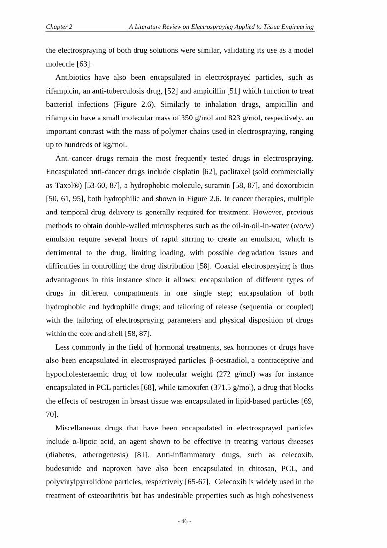
Chapter 2 A Literature Review on Electrospraying Applied to Tissue Engineering
- 46 -
the electrospraying of both drug solutions were similar, validating its use as a model
molecule [63].
Antibiotics have also been encapsulated in electrosprayed particles, such as
rifampicin, an anti-tuberculosis drug, [52] and ampicillin [51] which function to treat
bacterial infections (Figure 2.6). Similarly to inhalation drugs, ampicillin and
rifampicin have a small molecular mass of 350 g/mol and 823 g/mol, respectively, an
important contrast with the mass of polymer chains used in electrospraying, ranging
up to hundreds of kg/mol.
Anti-cancer drugs remain the most frequently tested drugs in electrospraying.
Encaspulated anti-cancer drugs include cisplatin [62], paclitaxel (sold commercially
as Taxol®) [53-60, 87], a hydrophobic molecule, suramin [58, 87], and doxorubicin
[50, 61, 95], both hydrophilic and shown in Figure 2.6. In cancer therapies, multiple
and temporal drug delivery is generally required for treatment. However, previous
methods to obtain double-walled microspheres such as the oil-in-oil-in-water (o/o/w)
emulsion require several hours of rapid stirring to create an emulsion, which is
detrimental to the drug, limiting loading, with possible degradation issues and
difficulties in controlling the drug distribution [58]. Coaxial electrospraying is thus
advantageous in this instance since it allows: encapsulation of different types of
drugs in different compartments in one single step; encapsulation of both
hydrophobic and hydrophilic drugs; and tailoring of release (sequential or coupled)
with the tailoring of electrospraying parameters and physical disposition of drugs
within the core and shell [58, 87].
Less commonly in the field of hormonal treatments, sex hormones or drugs have
also been encapsulated in electrosprayed particles. β-oestradiol, a contraceptive and
hypocholesteraemic drug of low molecular weight (272 g/mol) was for instance
encapsulated in PCL particles [68], while tamoxifen (371.5 g/mol), a drug that blocks
the effects of oestrogen in breast tissue was encapsulated in lipid-based particles [69,
70].
Miscellaneous drugs that have been encapsulated in electrosprayed particles
include α-lipoic acid, an agent shown to be effective in treating various diseases
(diabetes, atherogenesis) [81]. Anti-inflammatory drugs, such as celecoxib,
budesonide and naproxen have also been encapsulated in chitosan, PCL, and
polyvinylpyrrolidone particles, respectively [65-67]. Celecoxib is widely used in the
treatment of osteoarthritis but has undesirable properties such as high cohesiveness
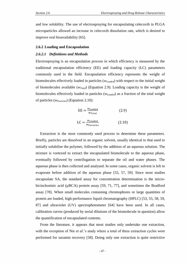
Section 2.6 Electrospraying and Drug Release Characteristics
- 47 -
and low solubility. The use of electrospraying for encapsulating celecoxib in PLGA
microparticles allowed an increase in celecoxib dissolution rate, which is desired to
improve oral bioavailability [65].
2.6.2 Loading and Encapsulation
2.6.2.1 Definitions and Methods
Electrospraying is an encapsulation process in which efficiency is measured by the
traditional encapsulation efficiency (EE) and loading capacity (LC) parameters
commonly used in the field. Encapsulation efficiency represents the weight of
biomolecules effectively loaded in particles (wLoaded) with respect to the initial weight
of biomolecules available (wTotal) (Equation 2.9). Loading capacity is the weight of
biomolecules effectively loaded in particles (wLoaded) as a fraction of the total weight
of particles (wParticles) (Equation 2.10):
(2.9)
(2.10)
Extraction is the most commonly used process to determine these parameters.
Briefly, particles are dissolved in an organic solvent, usually identical to that used to
initially solubilise the polymer, followed by the addition of an aqueous solution. The
mixture is vortexed to extract the encapsulated biomolecule to the aqueous phase,
eventually followed by centrifugation to separate the oil and water phases. The
aqueous phase is then collected and analysed. In some cases, organic solvent is left to
evaporate before addition of the aqueous phase [55, 57, 59]. Since most studies
encapsulate SA, the standard assay for concentration determination is the micro-
bicinchoninic acid (µBCA) protein assay [59, 71, 77], and sometimes the Bradford
assay [78]. When small molecules containing chromophores or large quantities of
protein are loaded, high-performance liquid chromatography (HPLC) [53, 55, 58, 59,
87] and ultraviolet (UV) spectrophotometer [64] have been used. In all cases,
calibration curves (produced by serial dilutions of the biomolecule in question) allow
the quantification of encapsulated contents.
From the literature, it appears that most studies only undertake one extraction,
with the exception of Nie et al.’s study where a total of three extraction cycles were
performed for suramin recovery [58]. Doing only one extraction is quite restrictive
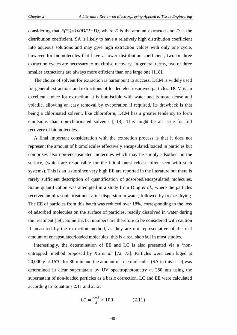
Chapter 2 A Literature Review on Electrospraying Applied to Tissue Engineering
- 48 -
considering that E(%)=100D/(1+D), where E is the amount extracted and D is the
distribution coefficient. SA is likely to have a relatively high distribution coefficient
into aqueous solutions and may give high extraction values with only one cycle,
however for biomolecules that have a lower distribution coefficient, two or three
extraction cycles are necessary to maximise recovery. In general terms, two or three
smaller extractions are always more efficient than one large one [118].
The choice of solvent for extraction is paramount to success. DCM is widely used
for general extractions and extractions of loaded electrosprayed particles. DCM is an
excellent choice for extraction: it is immiscible with water and is more dense and
volatile, allowing an easy removal by evaporation if required. Its drawback is that
being a chlorinated solvent, like chloroform, DCM has a greater tendency to form
emulsions than non-chlorinated solvents [118]. This might be an issue for full
recovery of biomolecules.
A final important consideration with the extraction process is that it does not
represent the amount of biomolecules effectively encapsulated/loaded in particles but
comprises also non-encapsulated molecules which may be simply adsorbed on the
surface, (which are responsible for the initial burst release often seen with such
systems). This is an issue since very high EE are reported in the literature but there is
rarely sufficient description of quantification of adsorbed/encapsulated molecules.
Some quantification was attempted in a study from Ding et al., where the particles
received an ultrasonic treatment after dispersion in water, followed by freeze-drying.
The EE of particles from this batch was reduced over 18%, corresponding to the loss
of adsorbed molecules on the surface of particles, readily dissolved in water during
the treatment [59]. Some EE/LC numbers are therefore to be considered with caution
if measured by the extraction method, as they are not representative of the real
amount of encapsulated/loaded molecules; this is a real shortfall in most studies.
Interestingly, the determination of EE and LC is also presented via a ‘non-
entrapped’ method proposed by Xu et al. [72, 73]. Particles were centrifuged at
20,000 g at 15°C for 30 min and the amount of free molecules (SA in this case) was
determined in clear supernatant by UV spectrophotometry at 280 nm using the
supernatant of non-loaded particles as a basic correction. LC and EE were calculated
according to Equations 2.11 and 2.12:
(2.11)
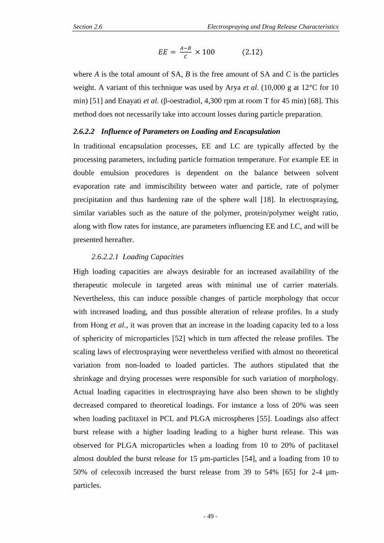
Section 2.6 Electrospraying and Drug Release Characteristics
- 49 -
(2.12)
where A is the total amount of SA, B is the free amount of SA and C is the particles
weight. A variant of this technique was used by Arya et al. (10,000 g at 12°C for 10
min) [51] and Enayati et al. (β-oestradiol, 4,300 rpm at room T for 45 min) [68]. This
method does not necessarily take into account losses during particle preparation.
2.6.2.2 Influence of Parameters on Loading and Encapsulation
In traditional encapsulation processes, EE and LC are typically affected by the
processing parameters, including particle formation temperature. For example EE in
double emulsion procedures is dependent on the balance between solvent
evaporation rate and immiscibility between water and particle, rate of polymer
precipitation and thus hardening rate of the sphere wall [18]. In electrospraying,
similar variables such as the nature of the polymer, protein/polymer weight ratio,
along with flow rates for instance, are parameters influencing EE and LC, and will be
presented hereafter.
2.6.2.2.1 Loading Capacities
High loading capacities are always desirable for an increased availability of the
therapeutic molecule in targeted areas with minimal use of carrier materials.
Nevertheless, this can induce possible changes of particle morphology that occur
with increased loading, and thus possible alteration of release profiles. In a study
from Hong et al., it was proven that an increase in the loading capacity led to a loss
of sphericity of microparticles [52] which in turn affected the release profiles. The
scaling laws of electrospraying were nevertheless verified with almost no theoretical
variation from non-loaded to loaded particles. The authors stipulated that the
shrinkage and drying processes were responsible for such variation of morphology.
Actual loading capacities in electrospraying have also been shown to be slightly
decreased compared to theoretical loadings. For instance a loss of 20% was seen
when loading paclitaxel in PCL and PLGA microspheres [55]. Loadings also affect
burst release with a higher loading leading to a higher burst release. This was
observed for PLGA microparticles when a loading from 10 to 20% of paclitaxel
almost doubled the burst release for 15 µm-particles [54], and a loading from 10 to
50% of celecoxib increased the burst release from 39 to 54% [65] for 2-4 µm-
particles.
Chapter 2 A Literature Review on Electrospraying Applied to Tissue Engineering
- 50 -
In terms of parameters affecting the loading capacity, an increase in
protein/polymer weight ratio dramatically decreased the loading capacity in the case
of emulsions of SA in PLA solution [73], while it increased for solid dispersion of
SA in chitosan solution [72]. In the case of coaxial electrospraying, drug loading
could be increased by increasing inner protein aqueous solution flow rate or
increasing inner protein concentration [77].
2.6.2.2.2 Encapsulation Efficiencies
Electrospraying is known as a technique which can give high encapsulation
efficiencies (EE), and indeed has been shown to reach 100% EE for doxorubicin and
rhodamine-loaded PLGA particles [50]. Electrospraying also presents the great
benefit that encapsulation of both types of drugs, hydrophilic and hydrophobic, are
efficiently obtained compared to traditional methods [50, 64], mainly since there is
no need of an emulsion step. In emulsion-based methods, the presence of both
aqueous and organic phases may indeed lead to preferential diffusion of the drug to
one phase or the other according to their hydrophilicity/hydrophobicity
characteristics and thus reducing final EE. This is avoided with electrospraying
where emulsions are not required.
EE depends case by case on the combination of drug/solvent/polymer selection,
where the hydrophilic nature of these components plays an important role. This may
be illustrated by considering the nature of the polymer itself, for example the
encapsulation of SA in a more hydrophobic polymer such as PCL has led to 28% EE
compared to 40% for PLGA microparticles electrosprayed in the same conditions
[71]. The use of hydrophilic additives should also be considered and it has been
shown that Pluronic® F-127, a highly hydrophilic copolymer used as a surfactant,
increased encapsulations efficiencies from 53.4% to 76.7% by using 5% and 10% of
Pluronic respectively in PLGA microparticles loaded with SA, by enhancing the w/o
emulsion stability. It was further stated that the use of a probe sonication to form the
emulsion could enhance the EE [71].
An increase in loading generally leads to a decrease in EE, as seen in
electrosprayed PLGA films loaded with paclitaxel, where a 5, 10, 15 and 30%
loading respectively led to 80, 71.9, 66.4 and 63% EE [57]. This was attributed to the
partition coefficient, referring to the equilibrium solubility of the drug in the polymer
against the equilibrium solubility of the drug in the solvent and responsible for
Section 2.6 Electrospraying and Drug Release Characteristics
- 51 -
diffusion of the drug into the polymer phase. With paclitaxel being more
hydrophobic and soluble in organic solvents, increasing the loading could have led to
preferential diffusion into the solvent, and thus reduced encapsulation [57]. In a
study from Xie et al., for similar polymer solutions and spraying conditions, an
increase of paclitaxel loading from 8% to 16% slightly decreased EE from 82% to
78% [55] in PLGA microparticles. This was also shown for PLA microparticles
encapsulating SA where EE decreased with increasing SA/PLA ratio and increased
with organic/aqueous phase ratio. This latter may be explained by an increase in
viscosity when increasing the organic/aqueous phase ratio, leading to better
encapsulation [73]. Furthermore, a strong correlation was found between SA/PLA
weight ratio and organic/aqueous phase ratio with respect to encapsulation
efficiencies. Size affects EEs as well, where smaller particle sizes lower the EE [64].
In the case of coaxial electrospraying, higher EE in both core and shell can be
obtained by encapsulating hydrophobic drugs in the core and hydrophilic drugs in the
shell [58]. In monoaxial electrospraying, similar EE were found for hydrophobic and
hydrophilic drugs (54% BDP and 56% SS, respectively) in PLA nanoparticles,
demonstrating the versatility of the technique. Loss of drugs can, however, be an
issue in electrospraying, mainly caused by spreading of the particles to the receiving
vessel walls and other manufacturing equipment. This was measured as 20% for SS-
loaded PLA nanoparticles sprayed in ethanol. When electrospraying in a cross-
linking solution however, an increase in the concentration of the cross-linking agent
(10% against 5%) led to a significant increase in EE of SA [72]. This was due to an
increased intermolecular interaction of the polymer and cross-linking agent when
increasing their respective concentrations, inhibiting the loss of SA into the
collection solution and improving EE. When gelation was incomplete, as seen for
higher flow rates, more SA was lost in the collection solution [72].
2.6.3 Molecule Dispersion
Controlled dispersion of the drug within the polymer matrix is of upmost importance
for consistent release. It was previously stated that drug concentration in a particle
matrix tends to decline as we move outwards from the centre with the increase of the
particle diameter as seen in rifampicin-loaded particles [52]. This is explained by the
diffusion mechanism of solutes, stating that an increase in the droplet size provides a
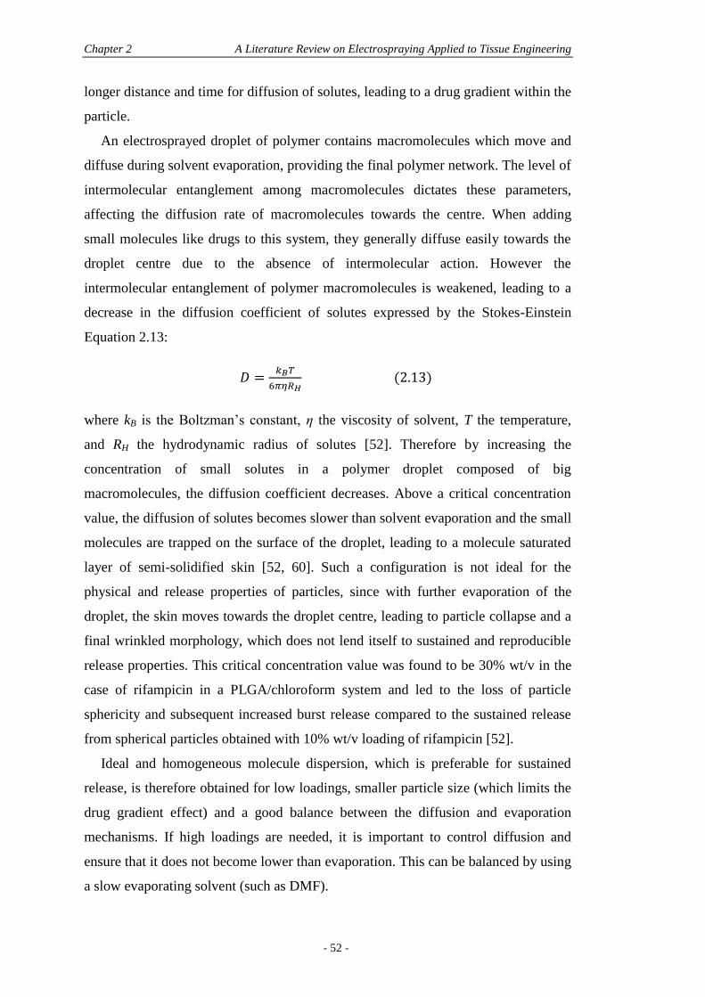
Chapter 2 A Literature Review on Electrospraying Applied to Tissue Engineering
- 52 -
longer distance and time for diffusion of solutes, leading to a drug gradient within the
particle.
An electrosprayed droplet of polymer contains macromolecules which move and
diffuse during solvent evaporation, providing the final polymer network. The level of
intermolecular entanglement among macromolecules dictates these parameters,
affecting the diffusion rate of macromolecules towards the centre. When adding
small molecules like drugs to this system, they generally diffuse easily towards the
droplet centre due to the absence of intermolecular action. However the
intermolecular entanglement of polymer macromolecules is weakened, leading to a
decrease in the diffusion coefficient of solutes expressed by the Stokes-Einstein
Equation 2.13:
(2.13)
where kB is the Boltzman’s constant, η the viscosity of solvent, T the temperature,
and RH the hydrodynamic radius of solutes [52]. Therefore by increasing the
concentration of small solutes in a polymer droplet composed of big
macromolecules, the diffusion coefficient decreases. Above a critical concentration
value, the diffusion of solutes becomes slower than solvent evaporation and the small
molecules are trapped on the surface of the droplet, leading to a molecule saturated
layer of semi-solidified skin [52, 60]. Such a configuration is not ideal for the
physical and release properties of particles, since with further evaporation of the
droplet, the skin moves towards the droplet centre, leading to particle collapse and a
final wrinkled morphology, which does not lend itself to sustained and reproducible
release properties. This critical concentration value was found to be 30% wt/v in the
case of rifampicin in a PLGA/chloroform system and led to the loss of particle
sphericity and subsequent increased burst release compared to the sustained release
from spherical particles obtained with 10% wt/v loading of rifampicin [52].
Ideal and homogeneous molecule dispersion, which is preferable for sustained
release, is therefore obtained for low loadings, smaller particle size (which limits the
drug gradient effect) and a good balance between the diffusion and evaporation
mechanisms. If high loadings are needed, it is important to control diffusion and
ensure that it does not become lower than evaporation. This can be balanced by using
a slow evaporating solvent (such as DMF).
Section 2.6 Electrospraying and Drug Release Characteristics
- 53 -
A few techniques have been used to assess the integration of drugs within the
polymer matrix of electrosprayed particles, although they do not allow for physical
visualisation of drugs within the droplets (although confocal laser scanning
microscopy may be used to look at fluorescently-labelled drugs). Differential
scanning calorimetry (DSC) relies on the fact that if a drug is well dispersed in the
polymer matrix, the melting transition of the drug will be suppressed either partially
or completely [59]. This theory was used for Taxol®-loaded PCL particles where
only a slight heat flow peak of Taxol® was observed in the physical mixture of PCL
and Taxol® [59]. The authors concluded that the drug was well-dispersed within the
matrix. The same theory was used for paclitaxel-loaded PLGA and PCL
microparticles where no peak at all was seen in the 150-250°C temperature range,
while paclitaxel normally has an endothermic peak of melting at 223°C [55]. From
this result, the authors stated that the paclitaxel was in an amorphous or disordered-
crystalline phase of a molecular dispersion or a solid solution state in the polymer
matrix. The same conclusion was made for hydrogel beads encapsulating paclitaxel-
loaded PLGA microspheres [53]. This was further seen in electrosprayed PLGA
films loaded with the same drug [57]. The authors even annealed their samples for 3
days at 60°C to facilitate a higher diffusion rate for dispersed drug molecules, but
still no crystalline peak of paclitaxel was observed for annealed samples, leading to
the conclusion that the drug was in a solid solution state within the matrix, as
compared to a metastable molecular dispersion [57]. A similar theory was used for
BDP and SS-loaded PLA nanoparticles where no melting peak at all was seen for
BDP-loaded particles and only a smaller and broader peak was seen in SS-loaded
particles [64]. The crystallinity of PLA was changed in the presence of both drugs,
namely higher when SS was encapsulated and lower when BDP was encapsulated.
This was tentatively explained by the presence of water, since SS was emulsified
before electrospraying, thus reducing evaporation rate, allowing for more polymer
diffusion and chains re-arrangement, and was thus responsible for the higher value
for crystallinity [64]. The crystallinity of all materials (BDP, SS and PLA) in the
nanoparticle formulations were decreased although the crystalline intensities were
distributed as 80% for BDP and 20% for PLA, or 54% for SS and 46% for PLA.
Importantly, no new peaks were seen in the DSC profiles, indicating no strong
physical or chemical interactions were present between the drugs and polymer. A
similar result was observed for celecoxib-loaded PLGA microparticles, where the
Chapter 2 A Literature Review on Electrospraying Applied to Tissue Engineering
- 54 -
melting endotherms of celecoxib shifted down or disappeared according to decreased
drug content, suggesting that the drug was molecularly dispersed within the PLGA
matrix [65]. The disappearance of the Tamoxifen peak for loaded PAA-Cholesterol
nanoparticles suggested the same result [70].
X-ray diffractometry (XRD) may also be used for determining the physical state
of a drug within polymeric matrices since characteristics of the peaks mark the
degree of crystallisation of the drug with the matrix. XRD previously showed that
paclitaxel was in an amorphous form in the PLGA matrix, even for up to 30% drug
loading, since no peak was seen in the expected range of temperature (200-250°C)
when analysing the polymeric matrix [57].
Analysis of surface chemistry by X-ray photoelectron spectroscopy (XPS) can
also give information regarding the distribution of drugs within microparticles, by
examining the C, N and O element compositions. This technique has been used to
show that paclitaxel was present on the surface layer of PLGA microparticles (with
up to 0.8% atomic mass concentration), a phenomena which is argued to be
responsible for the initial burst release seen in the in vitro release study [55]. XPS
showed that the amount of nitrogen increased with increasing paclitaxel contents (0-
30% loading) in electrosprayed PLGA films, attesting of the presence of the drug.
Confocal laser scanning microscopy (CLSM) is another way of qualitatively
looking at fluorescently labelled biomolecules encapsulated within particles. This
method allows for screening of cross-sections of a loaded particle through the entire
particle, for further 3D reconstruction. This powerful tool proves to be very useful
for visualising in 3D the biomolecule distribution inside the particles after
production, and studying the mechanisms of release from particles. CLSM has been
used successfully for other fabrication methods such as spray-drying [119], however
it has yet to be extensively utilised for visualisation purposes with electrosprayed
particles [50], although it would be very valuable, especially in combination with the
aforementioned analysis techniques for a more thorough characterisation of molecule
dispersion.
2.6.4 Release Kinetics
Polymeric microparticles for controlled drug delivery have been extensively studied
in the last 50 years and various reviews detail their preparation, the factors affecting
the release and the current difficulties faced during processes [17, 18, 26, 35, 120].
Section 2.6 Electrospraying and Drug Release Characteristics
- 55 -
Most of these reviews encompass microparticles made from traditional fabrication
techniques and limited information is available on release kinetics from
electrosprayed particles.
In general terms, release occurs through two different mechanisms; passive
diffusion and polymer degradation. Ideally a controlled release system would show a
zero-order release profile, meaning a constant release rate over time. However, the
release profile from particles is usually split in two distinct processes:
1. The initial burst release of molecules contained on and in the surface of the
particle due to the leaching occurring at the outer wall of the particle as it becomes
hydrated [18].
2. The slower and more constant release of molecule from the inner part of the
particle.
Release profiles can be affected by physical and chemical factors: the nature of
the polymer (molecular weight, blending, crystallinity), the nature of the loaded
molecule, its distribution and activity, the morphology of microspheres, their
porosity and size distribution [17, 18]. In electrospraying, similar parameters are able
to tailor release kinetics and they are discussed in the next section. Table 2.2
illustrates various electrospraying studies with the release profiles and corresponding
morphologies.
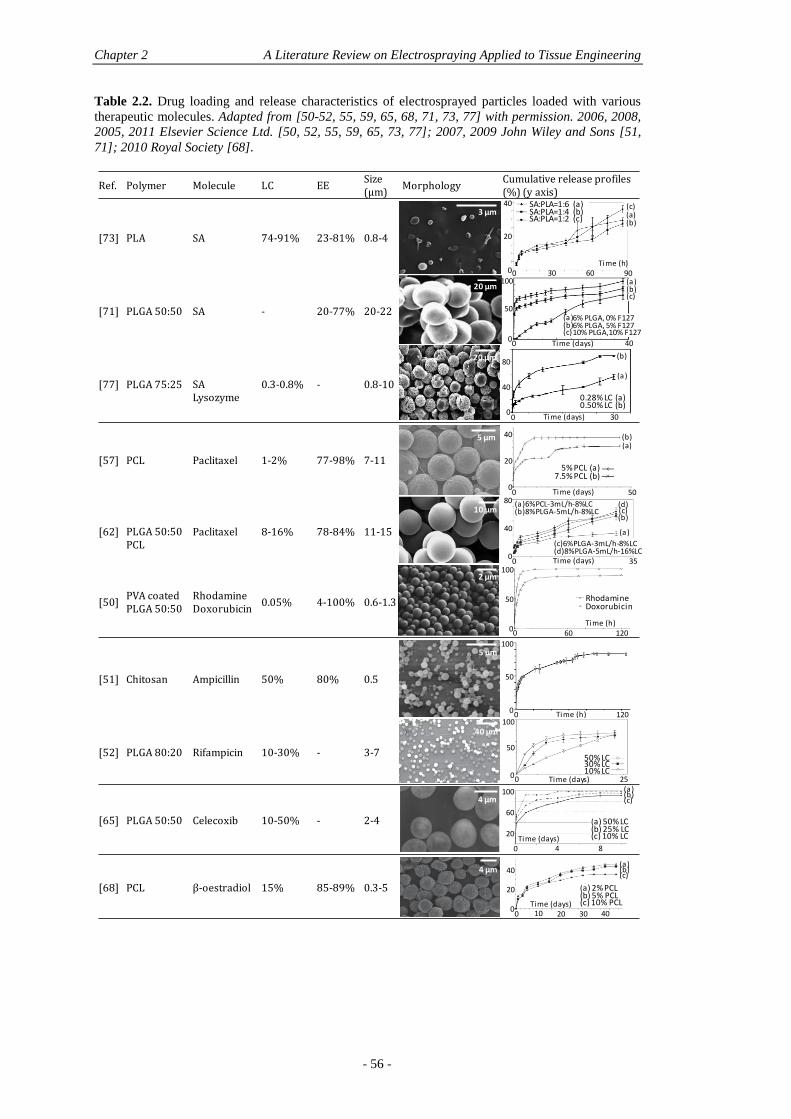
Chapter 2 A Literature Review on Electrospraying Applied to Tissue Engineering
- 56 -
Table 2.2. Drug loading and release characteristics of electrosprayed particles loaded with various
therapeutic molecules. Adapted from [50-52, 55, 59, 65, 68, 71, 73, 77] with permission. 2006, 2008,
2005, 2011 Elsevier Science Ltd. [50, 52, 55, 59, 65, 73, 77]; 2007, 2009 John Wiley and Sons [51,
71]; 2010 Royal Society [68].
Ref. Polymer Molecule LC EE Size (µm)
MorphologyCumulative release profiles (%) (y axis)
[73] PLA SA 74-91% 23-81% 0.8-4
[71] PLGA 50:50 SA - 20-77% 20-22
[77] PLGA 75:25 SA Lysozyme
0.3-0.8% - 0.8-10
[57] PCL Paclitaxel 1-2% 77-98% 7-11
[62] PLGA 50:50PCL
Paclitaxel 8-16% 78-84% 11-15
[50]PVA coated PLGA 50:50
RhodamineDoxorubicin
0.05% 4-100% 0.6-1.3
[51] Chitosan Ampicillin 50% 80% 0.5
[52] PLGA 80:20 Rifampicin 10-30% - 3-7
[65] PLGA 50:50 Celecoxib 10-50% - 2-4
[68] PCL β-oestradiol 15% 85-89% 0.3-5
0
50
100
0 60 120
RhodamineDoxorubicin
Time (h)
0 Time (h) 120
100
50
0
0
100
50
0 25Time (days)
50% LC30% LC10% LC
5 µm
5% PCL (a)7.5% PCL (b)
0 Time (days) 500
40
20
(a)(b)
10 µm
2 µm
5 µm
40 µm
4 µm
0Time (days)
4 8
20
60
100 (a)(b)(c)
(a) 50% LC(b) 25% LC(c) 10% LC
4 µm
0 10 20 30 40Time (days)
(a)(b)(c)
(a) 2% PCL(b) 5% PCL(c) 10% PCL
20
40
0 Time (days) 350
40
80 (a)6%PCL-3mL/h-8%LC(b)8%PLGA-5mL/h-8%LC
(c)6%PLGA-3mL/h-8%LC(d)8%PLGA-5mL/h-16%LC
0 6030 90
v
0
20
40
Time (h)
SA:PLA=1:6 (a)SA:PLA=1:4 (b)SA:PLA=1:2 (c) (a)
(b)
(c)
v50
100
0 40Time (days)0
(a)(b)(c)
6% PLGA, 0% F1276% PLGA, 5% F12710% PLGA,10% F127
(a )(b)(c)
0
40
80
0 Time (days) 30
(a)
(b)
0.28% LC (a)0.50% LC (b)
3 µm
20 µm
20 µm
(a)
(d)(c)(b)
0
Section 2.6 Electrospraying and Drug Release Characteristics
- 57 -
Size
The size of particles which encapsulate bioactive molecules is paramount in tailoring
release profiles. A larger surface area to volume ratio (smaller particles) leads to
faster release since particles are more easily penetrated by fluids, favouring easier
diffusion of drugs and faster degradation of the polymer matrix. However, it is
important to emphasise that it is not size itself that controls the release profiles but it
has more to do with the polymer/drug/solvent selection and processing parameters
that are used in each case, as explained in section 2.5.2.2. Therefore size is a result of
other variables which have an inter-dependent effect and need to be appropriately
correlated to truly control release kinetics.
In a study by Enayati et al. for instance, β-oestradiol-loaded PCL particles had
similar release pattern for mean sizes of 0.34, 0.8 and 4.6 µm, however release was
45, 42 and 36%, respectively, after 45 days, thus showing a reduced release for
increasing particle size [68]. This increase in size was actually due to an increase in
polymer content (2, 5 and 10%, respectively), showing that polymer concentration do
indeed provide bigger particle sizes but may also provide reduced release rates at the
same time. In this study, due to the nature of the polymer (PCL) where degradation is
unlikely to have occurred over a seven-week period, the release was due to diffusion
of β-oestradiol from the particles, proving that drugs loaded in smaller particles
comprising less polymeric bulk material are prone to better diffusion outside the
polymeric matrix and thus enhanced release [68]. However, burst release is also
more likely to happen from smaller particles. This was observed for paclitaxel-
loaded PCL particles where two formulations with similar sizes (9.45 and 9.52 µm)
showed a similar release pattern and amount released, while a slight decrease in size
to 8.68 µm gave the same release pattern but with a higher burst at the beginning
(11% compared to 7% burst within a day). This was again attributed to a higher
polymer concentration (5% PCL in DCM for the smaller size and 7.5% for the larger
size) which influenced the final size, where larger particles had a denser polymer
matrix and thus a reduced rate of diffusion, in turn reducing the initial burst release
[59]. When working with smaller concentrations, size is less affected although
release profiles can still show great differences. For instance, for an increase in
chitosan concentration from 1 to 2%, size was slightly higher, but not significantly
(7.48 and 8.11 µm, respectively), while a higher burst was observed for the reduced
concentration (7 and 2% after 4 days) leading to a final cumulative release of 33%
Chapter 2 A Literature Review on Electrospraying Applied to Tissue Engineering
- 58 -
and 21% for the 1% and 2% concentration formulations, respectively. Although an
increase in polymer concentration is generally shown to increase size and decrease
release rates/burst release at high concentrations, the contrary is seen for loadings.
An increase in loading is generally responsible for increased sizes too, but generates
faster release rates and burst, especially on the submicron scale [72]. This can be
seen for doxorubicin-loaded chitosan nanoparticles for example, where an increase in
loading from 0.25 to 1% doxorubicin increased the resultant particle size from 527.3
to 873 nm and led to 40% burst release within 3 hours while only a 20% burst release
was observed for the smaller sizes [95]. For microparticles, however, size is less
affected by loading although release is affected. For instance, in paclitaxel-loaded
PCL particles, when loading was increased from 7.9 to 15.8%, the resultant size was
very similar (15.2 and 15.2 µm, respectively) although burst release was 10 and 20%
after 1 day, and the final cumulative release reached 57 and 62%, respectively [55].
In the case of emulsions, the organic/aqueous phase factor has little effect on
release profiles although size is significantly affected, as a consequence from
decreased conductivity with increased organic phase, and thus increased size, as
explained in section 2.5.2.2. This was seen for SA-loaded PLA particles where at a
constant ratio of 1:4 SA/PLA, but increased organic/aqueous phase ratio ranging
from 6.7:1 to 20:1, size increased from 0.8 to 1.9 µm but showed similar release
pattern and amount released [73].
Another significant factor affecting release kinetics is the degree of agglomeration
of the particles. The burst release process is mainly diffusion-driven while the second
process providing a slower release is erosion-driven. It was shown by Almería et al.
that the burst release stage was greatly affected by particle agglomeration and
particle size, whereas the slower release part was much less dependent on particle
size [50]. Agglomeration however was shown to affects release kinetics for
hydrophilic biomolecules, since sizes of particle clusters result in orders of
magnitude larger than individual particles. This aggregation compromises the
reproducibility of release profiles and provides less cumulative release than dispersed
particles (Rhodamine B from PLGA electrosprayed particles) [50]. Coating
techniques may thus be used for preventing aggregation when electrospraying in
solution and enables tight control over particle size.
Section 2.6 Electrospraying and Drug Release Characteristics
- 59 -
Morphology
Along with size distribution, morphology is another major contributor for controlling
drug release behaviour and like size, morphology is directed by the
polymer/drug/solvent selection and processing parameters [59]. It was indeed shown
that wrinkled particles led to a burst release of 50% of cumulative release of SA form
PLGA particles in the first day, which was not seen for spherical particles with the
same size distribution (21 ± 2 µm average diameter) [71]. This is a direct
consequence of lower polymer concentration used in wrinkled particles (6%)
compared to dense and spherical particles made of 10% PLGA. More pores were
found in wrinkled particles allowing for molecule adsorption instead of
encapsulation. Water penetration is more accessible in porous particles and leads to
the rapid diffusion of adsorbed molecules, responsible for the high burst release. In
denser particles, the rate of water penetration is reduced, allowing for desirable zero-
order release kinetics.
Similarly to polymer concentration, molecular weight is another important factor
for tailoring particles and their release profiles, since both parameters direct the
viscosity of solutions. This was illustrated with PLGA capsules containing IGF-1,
made of low (5-15 kDa) and high MW (40-75 kDa) [29]. The release profiles were
similar, triphasic in nature, but with an initial burst which was more prevalent for the
low MW formulation, for same PLGA concentration and IGF-1 loading. The burst
was 5.5% compared to 7% and led to a final cumulative release of 10 and 12% for
high and low MW formulations, respectively. The morphology of high MW particles
was spherical while the low MW particles displayed an irregular morphology. This
was a consequence of weaker chain interactions in the low MW PLGA where
packing of polymer chains was looser than that of high MW PLGA, which allowed
the encapsulated IGF-1 to diffuse through the polymer more easily [29].
The solvent is another means to control particle morphology, due to different
evaporation rates that lead to more or less porous structures respectively. This will
ultimately condition the release kinetics as well, as seen with PLGA particles
containing doxorubicin, electrosprayed from a 2,2,2-trifluoroethanol (TFE) solution
and TFE-dimethyl sulfoxide (DMSO) mixture (vapour pressures at room temperature
of TFE and DMSO are 0.08 kPa and 10.09 kPa respectively). As expected, PLGA
particles electrosprayed from TFE were more porous than the ones from TFE-
Chapter 2 A Literature Review on Electrospraying Applied to Tissue Engineering
- 60 -
DMSO, leading to 77% compared to 52% of drug released by diffusion (burst),
respectively [50].
Nature of Polymer
It is accepted that degradation of polymeric particles initially occurs in amorphous
regions, followed by a slower degradation of the crystalline regions of particles [18].
Freiberg et al. stated that low crystallinity allows better drug dispersion and
increased drug-polymer interactions while the degree of crystallinity is also
influenced by the drug loading and the concentration and removal rate of organic
solvent [18]. Therefore, the use of polymers with highly crystalline structures such as
PCL enables the production of microparticles with uniform and reproducible
physical characteristics [83], but might be inadequate for optimal drug dispersion and
release characteristics. For instance, in a study from Ding et al., the cumulative
release of Taxol® from electrosprayed PCL particles (65k) did not exceed 37% of the
total amount of encapsulated Taxol® after 10 days of release (tested up to 50 days),
suggesting that a high percentage of drug aggregated after contact with the polymer
[59]. In a similar fashion, a study by Xie et al. showed that PCL microparticles
loaded with 8.1% paclitaxel were able to release only 32% of this load after 30 days
of in vitro incubation while PLGA microparticles loaded with the same amounts and
electrosprayed with the same conditions reached 60% of cumulative release [55].
Regions of high crystallinity and aggregated protein may likely contribute to the
incomplete release of the protein [91].
Responsive polymers such as elastin-like polypeptides can also release
biomolecules, such as doxorubicin, according to pH variation. However, in all cases
(pH; 2.5, 5.5 and 7.5), all systems suffered from burst release were maximum release
was achieved after 15 min only, and therefore they did not provide sustained release
[61].
Nature of Drug
Interactions between loaded molecules and polymers direct the location of molecules
within the polymer matrix (either encapsulated in the core or adsorbed on the surface
of the particle) and affect the kinetics of release [64]. In the case of coaxial
electrospraying for loading of multiple drugs within microcapsules, it was shown that
the nature of the drugs and their location within the microcapsules affected the
release patterns; loading of hydrophilic drug in the shell and hydrophobic drug in the
Section 2.6 Electrospraying and Drug Release Characteristics
- 61 -
core provided a sequential release, while the opposite led to the drugs being released
in parallel [58].
The physicochemical affinity of the drug with the polymer system has a great
influence on release kinetics. For similar size distributions and loadings, dramatic
differences can be observed when varying the hydrophilicity/hydrophobicity of the
drug encapsulated. For instance when rhodamine B (RHOB) and rhodamine B
octadecyl ester perchlorate (RHOBOEP) were used as hydrophilic and hydrophobic
drug surrogates respectively, 98% of RHOB was released within 1 day, while only
6% of total RHOBOEP was released after 5 days. This was explained by the strong
affinity of RHOBOEP with PLGA, preventing any initial burst release (RHOB and
RHOBOEP have octanol/water partition coefficients such that log KOW = 1.48 and 8-9
respectively). When compared with doxorubicin (DOX) (log KOW = 1.85), an
intermediate behaviour was observed where 60% of the drug was released in the first
24h and further 20% was released after 5 days. This was attributed to the different
partition coefficients of the two substances within PLGA [50]. The release of RHOB
will occur rapidly by diffusion of molecules inside the polymer matrix while DOX -
having a greater partition coefficient within PLGA - remains entrapped longer in the
hydrophobic porous regions of the matrix.
Additives
The use of additives can greatly affect the release kinetics, such as the use of
poly(ethylene glycol) (PEG), commonly used in traditional encapsulation processes.
Due to its hydrophilicity, PEG increases the degradation rate of the main polymer
matrix by rendering the overall polymer network more hydrophilic, increasing
swelling and thus accelerating release [121].
In co-axial electrospinning, for instance, an aqueous PDGF solution was
encapsulated in a blend of PCL:PEG nanofibres [122]. PEG acted as a porogen and
PDGF release reached 100% in 35 days with a relatively linear release profile, while
less than 1% of PDGF was released from the PCL nanofibres with no PEG in the
shell. The rate of protein release was shown to be controlled by the molecular weight
and concentration of PEG [122]. Johnson et al. showed that the amount of PEG co-
lyophilised with PLGA before encapsulation in discs was the dominating factor in
the rate of nerve growth factor (NGF), allowing modulation of the release [123].
Nevertheless, for particle fabrication methods based on emulsions, the efficiency of
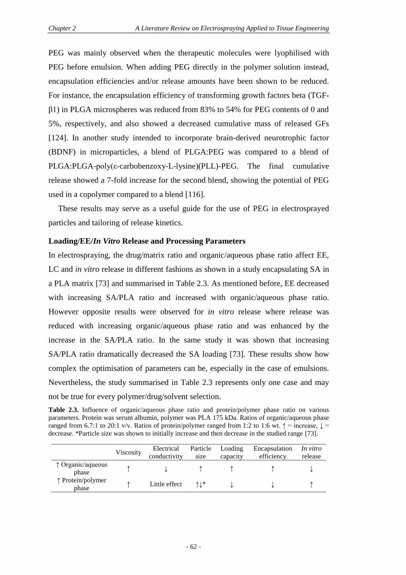
Chapter 2 A Literature Review on Electrospraying Applied to Tissue Engineering
- 62 -
PEG was mainly observed when the therapeutic molecules were lyophilised with
PEG before emulsion. When adding PEG directly in the polymer solution instead,
encapsulation efficiencies and/or release amounts have been shown to be reduced.
For instance, the encapsulation efficiency of transforming growth factors beta (TGF-
β1) in PLGA microspheres was reduced from 83% to 54% for PEG contents of 0 and
5%, respectively, and also showed a decreased cumulative mass of released GFs
[124]. In another study intended to incorporate brain-derived neurotrophic factor
(BDNF) in microparticles, a blend of PLGA:PEG was compared to a blend of
PLGA:PLGA-poly(ε-carbobenzoxy-L-lysine)(PLL)-PEG. The final cumulative
release showed a 7-fold increase for the second blend, showing the potential of PEG
used in a copolymer compared to a blend [116].
These results may serve as a useful guide for the use of PEG in electrosprayed
particles and tailoring of release kinetics.
Loading/EE/In Vitro Release and Processing Parameters
In electrospraying, the drug/matrix ratio and organic/aqueous phase ratio affect EE,
LC and in vitro release in different fashions as shown in a study encapsulating SA in
a PLA matrix [73] and summarised in Table 2.3. As mentioned before, EE decreased
with increasing SA/PLA ratio and increased with organic/aqueous phase ratio.
However opposite results were observed for in vitro release where release was
reduced with increasing organic/aqueous phase ratio and was enhanced by the
increase in the SA/PLA ratio. In the same study it was shown that increasing
SA/PLA ratio dramatically decreased the SA loading [73]. These results show how
complex the optimisation of parameters can be, especially in the case of emulsions.
Nevertheless, the study summarised in Table 2.3 represents only one case and may
not be true for every polymer/drug/solvent selection.
Table 2.3. Influence of organic/aqueous phase ratio and protein/polymer phase ratio on various
parameters. Protein was serum albumin, polymer was PLA 175 kDa. Ratios of organic/aqueous phase
ranged from 6.7:1 to 20:1 v/v. Ratios of protein/polymer ranged from 1:2 to 1:6 wt. ↑ = increase, ↓ =
decrease. *Particle size was shown to initially increase and then decrease in the studied range [73].
Viscosity Electrical
conductivity
Particle
size
Loading
capacity
Encapsulation
efficiency
In vitro
release
↑ Organic/aqueous
phase ↑ ↓ ↑ ↑ ↑ ↓
↑ Protein/polymer
phase ↑ Little effect ↑↓* ↓ ↓ ↑
Section 2.6 Electrospraying and Drug Release Characteristics
- 63 -
High drug contents are generally responsible for faster release rates [72]. For
higher drug loadings, initial rate of drug release increases, as seen for 30 and 50%
loading of rifampicin in PLGA-loaded particles while a 10% loading provided zero-
order release profile. It was stated that the drug concentration affects the drug
distribution in the particle matrix, with a gradual increasing gradient of concentration
present from the centre of the particle towards the surface, which was proportional to
the drug concentration [52]. In the case of microcapsules of PLGA containing an
aqueous solution of SA obtained by coaxial electrospraying, a 0.5% loading indeed
led to an increased burst release (almost double) as compared to the 0.3% loading,
although the release rates were identical once passed the burst release [77]. A similar
result was observed for paclitaxel-loaded PLGA microparticles where 10 and 20%-
loaded particles showed similar release kinetics, with only a higher initial burst
release over the first 2 days for the 20% formulation, followed by identical sustained
release kinetics from both formulations for the remaining 28 days [54]. By increasing
the drug content in a similar matrix type, a higher amount of porosity is created in the
matrix, thus the drug diffuses more easily through though the matrix, generating an
increased burst release [65].
Matrix Use
When loading electrosprayed particles into matrices such as hydrogels, different
release kinetics may be obtained by varying the gelation time, the concentration of
the cross-linking agent and particle loading. For example, paclitaxel-loaded PLGA
microspheres (12 µm average size) loaded in alginate macrobeads (1.61-1.68 mm
average size) provided different release kinetics. Although the authors did not show
the release profiles of non-entrapped microspheres, most alginate formulations
provided zero-order release kinetics of paclitaxel over 60 days reaching over 70%
cumulative release for the best formulation (50% microsphere loading, 5 min
gelation time and 1% CaCl2) [53]. The small burst release (maximum of 10%)
observed for the 50% microsphere-loaded formulations was reduced when alginate
beads were increasingly loaded to 80 and 90% of microspheres. However, overall
kinetics were also reduced reaching a maximum of 50% and 22% cumulative release
after 60 days for 80 and 90% microsphere-loaded formulations respectively. The
extent of cross-linking did not show a clear trend, since for the 50%-loaded
formulation, extended cross-linking resulted in lower release profiles while the
Chapter 2 A Literature Review on Electrospraying Applied to Tissue Engineering
- 64 -
opposite was seen for the 80% formulation and it was not significantly different for
the 90% formulation. This indicates that the microsphere loading in the matrix may
be a more determinant factor in release kinetics than the extent of cross-linking [53].
2.6.5 Denaturation
Electrospraying remains a process that employs organic solvents and therefore the
possibility of drug degradation and protein denaturation needs to be assessed and
compared to traditional encapsulation techniques to prove its superiority. So far,
limited studies have addressed this issue, nonetheless they present promising results.
The techniques generally employed are sodium dodecyl sulphate-polyacrylamide gel
electrophoresis (SDS-PAGE), Fourier transform infrared (FTIR), UV, and circular
dichroism (CD) spectroscopy [71, 77, 78, 104].
In the early stages of denaturation assessment by electrospraying, the model
protein SA was directly electrosprayed from an ethanol solution. Structural changes
were assessed by UV and CD spectroscopy showing that electrospraying of the
protein did not result in significant structural changes of SA, particularly at higher
concentrations (up to 20 mg/mL) [104]. When encapsulating the same protein in
PLGA microcapsules, no alteration in the secondary structure of SA was observed as
confirmed by comparing the CD spectra of SA before and after release from
polymeric microparticles [77]. In a study from Xie and Wang, the authors used SDS-
PAGE to investigate the protein integrity of SA released from PLGA (50:50)
microparticles after 38 days and characterised the secondary nature of SA by FTIR
and CD spectroscopy. They found that the released SA was almost identical to native
SA (after 1 day release) and no protein degradation was observed during the 38 days
release [71].
Although promising progress has been made, more studies are required to assess a
greater variety of molecules (drugs, growth factors, enzymes, DNA) in contact with
various organic solvents, and various polymers, since the purity and source of
molecule, and the nature of polymer can also influence the stability of loaded
molecules. Besides, SA remains a very stable protein which is unlikely to suffer from
denaturation. Typically, protein denaturation is potentially a major problem in
encapsulation processes involving organic solvents and it needs to be more
thoroughly assessed for the electrospraying technique. So far, when therapeutically
relevant proteins such as IGF-1, PDGF and VEGF were loaded in electrosprayed
Section 2.6 Electrospraying and Drug Release Characteristics
- 65 -
particles, authors discussed the bioactivity of the released proteins by performing
cell-proliferation assays rather than using the typical assays for the assessment of
protein degradation (SDS-PAGE, CD, etc.). Since in both studies the released
proteins were shown to be bioactive, i.e. induced cell proliferation, the authors
correlated their results with denaturation, concluding that the electrospraying
technique was efficient in protecting the growth factors from denaturation [29, 30].
This approach is a nice start to degradation assessment, showing that part of the
released proteins was indeed intact; however it remains a qualitative assessment and
does not conclude quantitatively on potential protein structural changes.
Traditionally, with emulsion techniques, additives such as surfactants, carrier
proteins, sugars, salts, amino acids and polymers are considered to protect the loaded
molecules [125]. Hydrophilic additives such as SA as an excipient [126] and
poly(ethylene glycol) (PEG) [123, 127, 128] have demonstrated good protection of
growth factors in traditional emulsion techniques. However such use has not yet been
seen in electrospraying since there is little focus on denaturation of loaded proteins,
where in most studies, loadings, encapsulation efficiencies and in vitro release
profiles of electrosprayed particles remain the most discussed characteristics of these
systems. This approach is not ideal when one considers that denatured proteins will
ultimately not fulfill their intended function, despite whether they have proven to be
ideally loaded, encapsulated or released. As discussed earlier, bioactivity assessment
is an indirect way of assessing denaturation, although it does not provide thorough
description of structural changes of proteins. Therefore, although the denaturation of
protein drugs seem to be minimal through the electrospraying process, as seen with
bioactivity assays, more extensive denaturation studies are required. To this end, the
use of appropriate additives for the electrospraying technique may be identified to
fight any potential degradation of molecules. To date, only Xie et al. have published
the use of Pluronic® F-127 as an additive to tailor and enhance the protection of SA
in PLGA electrosprayed particles [71].
Another potential disadvantage of electrospraying is the use of electric fields,
since they intensify around the highly charged droplets in the course of solvent
evaporation. Such high fields may induce conformational changes of the bioactive
molecule, leading to denaturation and thus loss of bioactivity. It was indeed proven
that electrospinning of collagen out of fluoroalcohols denatured collagen to gelatin
due to the presence of high voltage [129]. Nevertheless, this hypothesis is
Chapter 2 A Literature Review on Electrospraying Applied to Tissue Engineering
- 66 -
counterbalanced in the literature by the fact that, in electrospraying, the droplet size
is on the micro- to nano-scale, allowing for solvent evaporation to occur over
milliseconds, which is considered too short to have significant effects on
denaturation [44].
2.6.6 Bioactivity
The bioactivity of electrosprayed molecules was first assessed by electrospraying
insulin from an acidic water-ethanol solution. Bioactivity was assessed by comparing
the insulin receptor binding properties from electrospray-processed insulin and
control insulin. No significant differences were observed and the authors further
stated that the electrospraying technique was sufficiently ‘gentle’ not to hinder the
insulin biological activity [44]. Progressing towards the bioactivity of molecules
encapsulated within a polymeric matrix, several types of tests involving different cell
lines are presented, according to the type of encapsulated molecule: protein, anti-
cancer drug, anti-bacterial drug, antibiotic, etc.
The most commonly used model protein encapsulated in electrosprayed particles
is SA. However, SA’s bioactivity after encapsulation is rarely studied. Interestingly,
in a study from Xie et al., PLGA microparticles were used to encapsulate SA,
however lysozyme was used as the ‘model protein’ to study the bioactivity of
entrapped molecules, although SA was the focus of all other characterisations in the
paper [71]. The concentration of released lysozyme from lysozyme-loaded PLGA
microparticles was quantified by characterising the rate of lysis of Micrococcus
lysodeikticus cells by lysozyme after one day of incubation with particles. 92% of
bioactivity was calculated and it was stipulated to be much higher than with
traditional encapsulation methods (30-80%) [71]. In a similar study from the same
authors, the same assay was used for PLGA microcapsules made by coaxial
electrospraying and lysozyme bioactivity reached this time 94.6% after in vitro
release [77]. Although promising, both these studies mainly described the
encapsulation of SA (denaturation, encapsulation efficiencies and release) but used
lysozyme for depicting bioactivity. This creates a gap in characterisation since results
may not necessarily directly translate from one molecule to the other: since SA (a
plasma protein) and lysozyme (an enzyme) have different structures and size (66.4
kg/mol and 14.7 kg/mol respectively), thus they may be affected by the
electrospraying process in a different way, likely leading to different results.
Section 2.6 Electrospraying and Drug Release Characteristics
- 67 -
When encapsulating anti-cancer drugs such as paclitaxel, bioactivity is generally
assessed by Coumarin-6 (C6) glioma cells (brain tumour cells) inhibition with cell
cycling analysis and 3-(4,5-dimethylthiazol-2-yl)-5-(3-carboxymethoxyphenyl)-2-(4-
sulfophenyl)-2H-tetrazolium (MTS) assay [55]. In the study from Xie et al., cell
viability was hardly affected by particle concentration but was significantly
decreased with increasing exposure time (1 to 5 days), showing a delayed cytotoxic
effect of particles, equivalent to Taxol® treatment at day 4 and 5 only [55]. The same
cytotoxicity test was used for electrosprayed PLGA films loaded with paclitaxel [57]
where a decrease of C6 glioma cell viability compared to unloaded films was clearly
seen, while an increase in the loading (5 to 30%) showed only a slight decrease in
cell viability (from around 65% to 52% viability) without being statistically
significant. In another study from Nie et al. where paclitaxel and suramin were
coaxially encapsulated in microcapsules, a continued marginal increase in apoptotic
activity of C6 glioma cells was shown after 9 days, proving the efficiency of the
capsule system to deliver anti-cancer agents in a sustained way. Interestingly, cellular
recovery was observed in free drug treated groups, indicative of the limitations of
systemic drug administration, providing only short and acute exposure due to low
terminal half-life of paclitaxel and suramin [58]. In another study the same authors
showed that apoptotic activity was increased with the delivery systems compared to
the free Taxol® groups over 9 days. They also found an increased apoptotic activity
for their co-delivery system compared to single delivery with the combination
‘suramin in the core’ and ‘paclitaxel in the shell’ (S/P) outperforming the opposite
formulation (P/S). This could be correlated with in vitro release results where the S/P
formulation released higher doses of drugs compared to the P/S formulation [87].
A similar result was observed by measuring in vitro cellular apoptosis from
alginate macrobeads containing electrosprayed PLGA microspheres releasing
paclitaxel. Although the Taxol® control group gave high apoptosis of C6 glioma
cells at day 2, it decreased at day 4 and 6 while beads formulations were giving
increased and significantly higher apoptosis over time, demonstrating the potential of
the delivery system to sustain therapeutic levels of paclitaxel [53].
When loading antibiotics to treat antibacterial infections such as ampicillin or
ripamficin in electrosprayed particles, bioactivity can be assessed by measuring the
zone of inhibition in contact with sensitive bacterial strain such as E. coli DH5α in
the case of ampicillin. When using such test, the bioactivity of ampicillin released
Chapter 2 A Literature Review on Electrospraying Applied to Tissue Engineering
- 68 -
from chitosan particles was proven by a similar inhibition zone for loaded particles
and for the same amount of free drug [51]. However a very small inhibition zone was
also observed with unloaded particles, which the authors attributed to the inherent
antibacterial activity of chitosan. This result may be further investigated to ensure the
non-cytotoxicity of unloaded particles before loading of any therapeutic molecule.
For tissue regeneration and mainly angiogenesis, when growth factors such as
IGF-1, PDGF and VEGF were loaded in electrosprayed particles, their bioactivity
was respectively assessed by a smooth muscle cell (SMC) proliferation assay for
IGF-1 [29] and human umbilical vein endothelial cells (HUVECs) and lung
fibroblasts (LF) proliferation assays for VEGF and PDGF respectively [30]. The
SMC viability was assessed by a (3-(4,5-Dimethylthiazol-2-yl)-2,5-
diphenyltetrazolium bromide (MTT) assay and was shown to be significantly
increased over a 4 week period with exposure of released IGF-1. The results showed
that the bioactivity of IGF-1 was dependent on: the amount of IGF-1 loaded; the
amount of PLGA and its molecular weight. Briefly, IGF-1 demonstrated more
bioactivity for higher PLGA concentration, higher IGF-1 loadings and lower
molecular weight PLGA [29]. The viability of HUVECs and fibroblasts used for
determining the bioactivity of PDGF and VEGF was assessed by the PicoGreen®
dsDNA quantitation kit. The bioactivity of both GFs was shown to be high after two
days in vitro indicating minimal changes to the proteins during the electrospraying
process (around 80-90%). Interestingly, bioactivity decreased to less than 21% after
21 days, which authors attributed to the in vitro conditions that were too harsh for
growth factors, prone to oxidation and pH dependent deamidation in the in vitro
context [30].
When encapsulating therapeutic molecules in polymeric devices, the use of PEG
as an additive is shown to affect the release profiles, but also known to protect the
bioactivity of encapsulated molecules. PEG has not been used yet in electrosprayed
particles, although other polymeric devices have proven its benefits. For instance
Morita et al. indicated that co-lyophilisation of PEG and horseradish peroxidase
before exposure to organic solvents increased the retention of bioactivity [127].
Johnson et al. confirmed this theory by showing significantly more retention of nerve
GF (NGF) when PEG was co-lyophilised before encapsulation in PLGA discs [123].
Co-lyophilisation of PEG with therapeutic molecules may thus be considered in
electrospraying when the solid dispersion method is used for enhanced bioactivity.
Section 2.6 Electrospraying and Drug Release Characteristics
- 69 -
2.6.7 In Vivo Performance
Most studies on electrosprayed particles loaded with therapeutic molecules are done
within an in vitro context. This approach is very important so that parameters can be
tailored and optimised in the first instance, before the use of animals to further
validate the optimised formulations. However, in vivo data remains essential for
translation of electrosprayed particles loaded with therapeutic molecules to the clinic.
Owing to electrospraying, as applied to biological loadings, being in its relative
infancy, only limited in vivo data is currently available, although these studies do
show promising results.
Most in vivo studies involve the assessment of tumour treatment by sustained
release of anti-cancer agents such as paclitaxel and suramin [53, 54, 87]. In the study
from Naraharisetti et al. for instance, 10 and 20% wt of paclitaxel were loaded in
PLGA 50:50 particles by electrospraying from a DCM solution, providing final
microparticles of 15.0 µm in diameter within a narrow size distribution of 1.7 µm
[54]. C6 glioma cells were inoculated subcutaneously to BALB/c nude mice and
loaded particles were injected to the tumour in two doses on day 14 and 28 at 0.5 mg
paclitaxel/injection. A control injection of 1 mg of commercial paclitaxel (Taxol®)
was injected only at day 14 for comparison. All the groups showed improved tumour
suppression over the placebo control and cytotoxicity of the microparticles was
evident in the analysis by hematoxylin and eosin staining of the tumour tissue when
compared with the placebo and commercial Taxol® control. Both in vitro release
profiles from 10 and 20%-loaded particles showed similar release kinetics, with an
initial burst release over the first 2 days before sustained release for the further 28
days, with only the burst being higher for the 20% formulation. Such burst release
was shown to be more effective in treating the tumour since the 10% drug-loaded
group performed poorly compared to the 20% drug-loaded group and the Taxol®
control (10% drug-loaded group had to be sacrificed at 14 days due to excessive
tumour volume, and a second injection at 28 days could not therefore be performed)
[54].
In a similar study from Ranganath et al. (Figure 2.7A-C), monodisperse
paclitaxel-loaded PLGA microspheres were obtained by electrospraying, with an
average size of 11.79 ± 2.79 µm and a smooth, spherical morphology [53]. The
loaded microspheres were further loaded in alginate macrobeads (1.61-1.68 mm
average size) (Figure 2.7A) and presented various release profiles according to
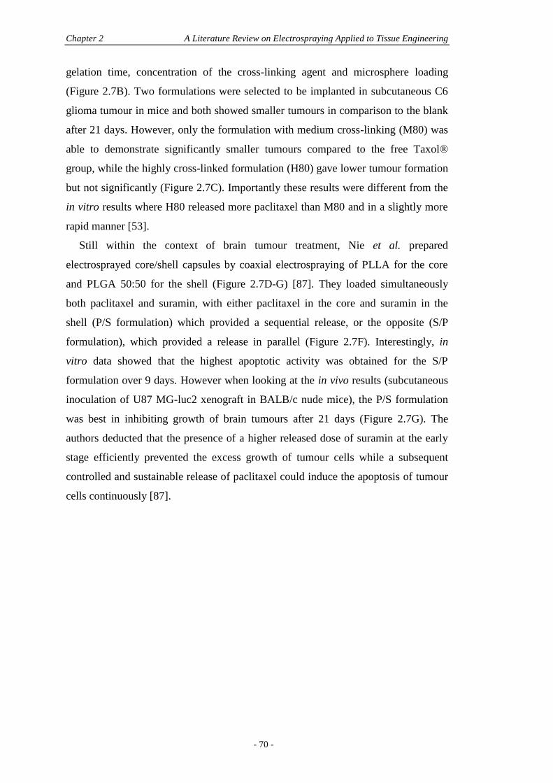
Chapter 2 A Literature Review on Electrospraying Applied to Tissue Engineering
- 70 -
gelation time, concentration of the cross-linking agent and microsphere loading
(Figure 2.7B). Two formulations were selected to be implanted in subcutaneous C6
glioma tumour in mice and both showed smaller tumours in comparison to the blank
after 21 days. However, only the formulation with medium cross-linking (M80) was
able to demonstrate significantly smaller tumours compared to the free Taxol®
group, while the highly cross-linked formulation (H80) gave lower tumour formation
but not significantly (Figure 2.7C). Importantly these results were different from the
in vitro results where H80 released more paclitaxel than M80 and in a slightly more
rapid manner [53].
Still within the context of brain tumour treatment, Nie et al. prepared
electrosprayed core/shell capsules by coaxial electrospraying of PLLA for the core
and PLGA 50:50 for the shell (Figure 2.7D-G) [87]. They loaded simultaneously
both paclitaxel and suramin, with either paclitaxel in the core and suramin in the
shell (P/S formulation) which provided a sequential release, or the opposite (S/P
formulation), which provided a release in parallel (Figure 2.7F). Interestingly, in
vitro data showed that the highest apoptotic activity was obtained for the S/P
formulation over 9 days. However when looking at the in vivo results (subcutaneous
inoculation of U87 MG-luc2 xenograft in BALB/c nude mice), the P/S formulation
was best in inhibiting growth of brain tumours after 21 days (Figure 2.7G). The
authors deducted that the presence of a higher released dose of suramin at the early
stage efficiently prevented the excess growth of tumour cells while a subsequent
controlled and sustainable release of paclitaxel could induce the apoptosis of tumour
cells continuously [87].
Section 2.6 Electrospraying and Drug Release Characteristics
- 71 -
Figure 2.7. (A) Representative scanning electron microscope (SEM) image of paclitaxel-loaded
PLGA microspheres (large arrow) entrapped in an alginate matrix (small arrow). Scale bar is 200 µm.
(B) In vitro release of paclitaxel from different formulations of microspheres entrapped in the alginate
matrix. L80, M80 and H80 correspond to different degrees of cross-linking (low, medium, high) with
1, 5, 15 min gelation time and 0.5, 1, 2% wt) of CaCl2 concentration, respectively. (C) In vivo
subcutaneous C6 tumour volume profiles of mice treated with different groups for 21 days (n = 5).
The control group had no beads and no drug; the placebo group was implanted with alginate
macrobeads but no drug; the Taxol® group received an injection of 180 µg of Taxol® directly in the
tumour mass; and animals in the H80 and M80 were implanted with 2 mg of alginate beads loaded
with microspheres containing an average amount of 162 µg of paclitaxel per animal [53]. (D-E)
Representative SEM images of PLLA/PLGA capsules loaded with (D) P/S formulation (paclitaxel
(PTX) in the core and suramin (SRM) in the shell) and (E) S/P formulation (SRM in the shell and
PTX in the core). Scale bar is 100 µm. (F) In vitro release of PTX and SRM from P/S and S/P
formulations. (G) In vivo subcutaneous U87 MG-luc2 tumour progression profile over the period of
treatment measured as normalised bioluminescence intensity (n = 5). The blank group received no
injection of drug; the placebo group was implanted with blank particles; the S/O group received
particles loaded with only suramin in the core while particles were loaded only with paclitaxel in the
P/O group [87]. Adapted from [53, 87] with permission. 2009 Springer [53]; 2010 Elsevier Science
Ltd. [87].
The results from both these studies underline the versatility of the electrospraying
technique being able to generate different release profiles according to the processing
parameters (in these cases being the drug loading [54], the extent of matrix cross-
linking [53] and the location of loaded drugs [87]) and generating different in vivo
results. Importantly, an initial burst release before the onset of a linear release was
shown to be more effective in tumour suppression and provided important feedback
for tailoring in vitro release profiles, showing that zero-order release kinetics are not
always desired for efficient therapeutic effect [54]. The importance of undergoing in
vivo studies is also shown to be paramount when looking at the study from
Ranganath et al. and Nie et al., where in vivo results may give different results to
what would be extrapolated from the in vitro data [53, 87].
Cu
mu
lati
ve p
aclit
axel
rel
ease
(%
)
100
60
20
0 20 40 60Time (days)
H80M80L80
Sub
cuta
neo
us
tum
ou
r vo
lum
e (m
m3 )0
1000
2000
3000
Treatment period (days)0 7 14 21
ControlPlaceboTaxol
H80
M80
A B C
Weeks after cell inoculation
0.1
10
100
0 1 2 3
BlankPlacebo
S/OP/OS/PP/S
No
rmal
ised
BLI
sig
nal
st
ren
gth
D
E
Time (days)
Cu
mu
lati
ve r
elea
se (
%)
0
20
40
60
80
100
0 6 12 18 24 30
P/SP/SS/PS/P
F G
Chapter 2 A Literature Review on Electrospraying Applied to Tissue Engineering
- 72 -
2.7 THE USE OF ELECTROSPRAYED PARTICLES IN ELECTROSPUN
SCAFFOLDS
2.7.1 Electrospun Nanofibres and Drug Delivery
Amongst the many scaffolds that have been generated to date in the field of tissue
engineering (TE), some of the most promising are the scaffolds produced which
comprise nanofibre structures [19, 130]. The nanoscale could be argued as being the
most realistic scale to approach when mimicking the architecture of natural tissues.
Nanofibre scaffolds are distinctive compared to scaffolds at the micro- or macro-
scale owing to their similarity to natural extracellular matrices, like collagens, which
are the major protein components of many tissues including skin, tendon, ligament
and bone. Collagen is characterised by a fibrillar structure shown to enhance cell
attachment, proliferation and differentiation in tissue culture [19]. For this reason,
engineers aim to mimic its structure whilst fabricating engineered tissues to closely
resemble the native tissues. In addition, the high surface to volume ratio of nanofibre
scaffolds is highly favourable for drug loading, while its high porosity and
interconnected pores facilitates nutrient and waste exchange during tissue
regeneration. These scaffolds can also be further modified by various 3D surface
modification techniques to incorporate other valuable features of the extracellular
matrix [19]. Nanofibre scaffolds are studied in various areas of TE: in neural TE,
where uniaxially aligned nanofibres can be used to guide the growth of neurons
[131], in bone TE, where nanofibres may be mixed with hydroxyapatite (HA) to
mimic the bone extracellular matrix which is mainly composed of collagen and HA
[21, 131], and in cartilage TE, where nanofibre meshes can support cell spreading
and growth of chondrocytes [21].
Three main techniques have recently emerged in the production of nanofibres:
electrospinning, phase separation and self-assembly. The two first techniques mainly
use polymeric materials due to their ease of processability and capacity to provide a
large variety of cost-effective materials. All methods can produce nanofibres, even
though electrospinning has been shown to generate larger diameter nanofibres on the
upper end of the nano-range of natural collagen, rather considered to be submicron
[130]. Electrospinning remains the most widely used technique for production of
nanofibres, due to numerous advantages when compared to the other techniques; it is
simple, cost effective, reproducible and versatile: a wide range of natural and
Section 2.7 The Use of Electrosprayed Particles in Electrospun Scaffolds
- 73 -
synthetic polymer solutions can be used (collagen, silk fibroin, PCL, PLGA,
polyurethane (PU), poly(methyl methacrylate) (PMMA), etc.) and the method allows
for control of fibre diameter and alignment [19, 21, 130, 132] (Examples include 30-
120 nm for silk fibroin [133], 250-800 nm for PCL [134, 135] and 200-1,000 nm for
PLGA [136]).
Electrospinning is an electrohydrodynamic variant of electrospraying which uses
identical apparatus. Compared to electrospraying, solution electrospinning requires
polymer solutions with higher viscosity, which can be obtained by using higher
molecular weights or most generally higher polymer concentrations that ensure at
least 2.5 entanglements per polymer chain [102]. The regime used for
electrospinning must be in the semi-dilute highly entangled regime where ratio C >
3Cov which can be up to 10Cov for obtaining uniform fibres, and which depends on
the molecular weight distribution of the polymer chains in solution [103].
Nanofibres have been investigated as drug delivery vehicles as well, where drugs
could be dissolved or dispersed in the polymer solution before electrospinning [137]
or by using coaxial electrospinning wherein a secondary polymer solution containing
the biomolecules is electrospun within the core of the forming nanofibre [122, 138].
The tissue-conductive only scaffold then becomes a tissue-inductive scaffold by
releasing bioactive agents capable of inducing specific tissue treatment. Nanofibre
scaffolds applied to drug delivery have predominantly been focused on the loading of
antibiotics and anti-cancer agents [23], and there have been several reports regarding
the incorporation of growth factors into these scaffolds [25, 122, 139-142]. More
details on electrospinning and drug delivery can be found to review by Sill and von
Recum [143].
Although direct incorporation of drugs into nanofibres seems promising, there is
presently a lack of characterisation of these systems. For instance some studies have
been done in vitro, while the understanding of scaffold behaviour and effectiveness
in vivo is essential for clinical applicability of these devices [23]. In addition,
drawbacks such as low reproducibility do not allow sufficient control over drug
distribution and thus insufficient control of the release profiles. This impairs both
reproducible pharmacokinetics and pharmacodynamics. Drug aggregation in solution
is another issue which can lead to denaturation and non-homogeneous distribution
within the scaffold after processing [25, 140]. Importantly, when the scaffold is
responsible for load bearing and drug delivery simultaneously, direct incorporation
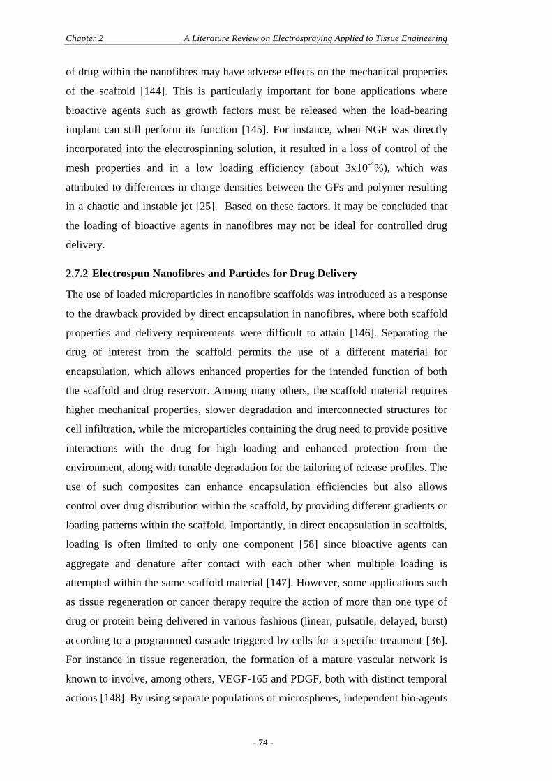
Chapter 2 A Literature Review on Electrospraying Applied to Tissue Engineering
- 74 -
of drug within the nanofibres may have adverse effects on the mechanical properties
of the scaffold [144]. This is particularly important for bone applications where
bioactive agents such as growth factors must be released when the load-bearing
implant can still perform its function [145]. For instance, when NGF was directly
incorporated into the electrospinning solution, it resulted in a loss of control of the
mesh properties and in a low loading efficiency (about 3x10⁻⁴
%), which was
attributed to differences in charge densities between the GFs and polymer resulting
in a chaotic and instable jet [25]. Based on these factors, it may be concluded that
the loading of bioactive agents in nanofibres may not be ideal for controlled drug
delivery.
2.7.2 Electrospun Nanofibres and Particles for Drug Delivery
The use of loaded microparticles in nanofibre scaffolds was introduced as a response
to the drawback provided by direct encapsulation in nanofibres, where both scaffold
properties and delivery requirements were difficult to attain [146]. Separating the
drug of interest from the scaffold permits the use of a different material for
encapsulation, which allows enhanced properties for the intended function of both
the scaffold and drug reservoir. Among many others, the scaffold material requires
higher mechanical properties, slower degradation and interconnected structures for
cell infiltration, while the microparticles containing the drug need to provide positive
interactions with the drug for high loading and enhanced protection from the
environment, along with tunable degradation for the tailoring of release profiles. The
use of such composites can enhance encapsulation efficiencies but also allows
control over drug distribution within the scaffold, by providing different gradients or
loading patterns within the scaffold. Importantly, in direct encapsulation in scaffolds,
loading is often limited to only one component [58] since bioactive agents can
aggregate and denature after contact with each other when multiple loading is
attempted within the same scaffold material [147]. However, some applications such
as tissue regeneration or cancer therapy require the action of more than one type of
drug or protein being delivered in various fashions (linear, pulsatile, delayed, burst)
according to a programmed cascade triggered by cells for a specific treatment [36].
For instance in tissue regeneration, the formation of a mature vascular network is
known to involve, among others, VEGF-165 and PDGF, both with distinct temporal
actions [148]. By using separate populations of microspheres, independent bio-agents
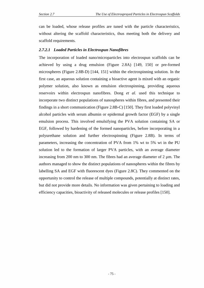
Section 2.7 The Use of Electrosprayed Particles in Electrospun Scaffolds
- 75 -
can be loaded, whose release profiles are tuned with the particle characteristics,
without altering the scaffold characteristics, thus meeting both the delivery and
scaffold requirements.
2.7.2.1 Loaded Particles in Electrospun Nanofibres
The incorporation of loaded nano/microparticles into electrospun scaffolds can be
achieved by using a drug emulsion (Figure 2.8A) [149, 150] or pre-formed
microspheres (Figure 2.8B-D) [144, 151] within the electrospinning solution. In the
first case, an aqueous solution containing a bioactive agent is mixed with an organic
polymer solution, also known as emulsion electrospinning, providing aqueous
reservoirs within electrospun nanofibres. Dong et al. used this technique to
incorporate two distinct populations of nanospheres within fibres, and presented their
findings in a short communication (Figure 2.8B-C) [150]. They first loaded polyvinyl
alcohol particles with serum albumin or epidermal growth factor (EGF) by a single
emulsion process. This involved emulsifying the PVA solution containing SA or
EGF, followed by hardening of the formed nanoparticles, before incorporating in a
polyurethane solution and further electrospinning (Figure 2.8B). In terms of
parameters, increasing the concentration of PVA from 1% wt to 5% wt in the PU
solution led to the formation of larger PVA particles, with an average diameter
increasing from 200 nm to 300 nm. The fibres had an average diameter of 2 µm. The
authors managed to show the distinct populations of nanospheres within the fibres by
labelling SA and EGF with fluorescent dyes (Figure 2.8C). They commented on the
opportunity to control the release of multiple compounds, potentially at distinct rates,
but did not provide more details. No information was given pertaining to loading and
efficiency capacities, bioactivity of released molecules or release profiles [150].
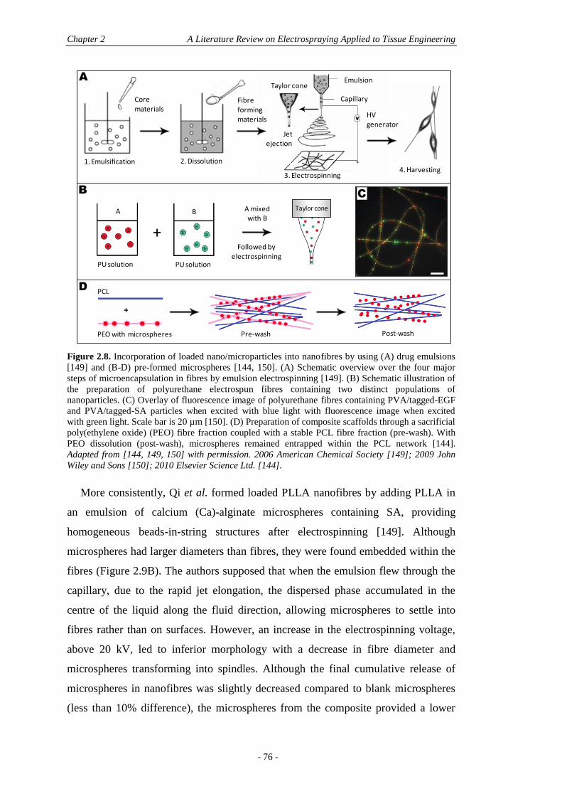
Chapter 2 A Literature Review on Electrospraying Applied to Tissue Engineering
- 76 -
Figure 2.8. Incorporation of loaded nano/microparticles into nanofibres by using (A) drug emulsions
[149] and (B-D) pre-formed microspheres [144, 150]. (A) Schematic overview over the four major
steps of microencapsulation in fibres by emulsion electrospinning [149]. (B) Schematic illustration of
the preparation of polyurethane electrospun fibres containing two distinct populations of
nanoparticles. (C) Overlay of fluorescence image of polyurethane fibres containing PVA/tagged-EGF
and PVA/tagged-SA particles when excited with blue light with fluorescence image when excited
with green light. Scale bar is 20 µm [150]. (D) Preparation of composite scaffolds through a sacrificial
poly(ethylene oxide) (PEO) fibre fraction coupled with a stable PCL fibre fraction (pre-wash). With
PEO dissolution (post-wash), microspheres remained entrapped within the PCL network [144].
Adapted from [144, 149, 150] with permission. 2006 American Chemical Society [149]; 2009 John
Wiley and Sons [150]; 2010 Elsevier Science Ltd. [144].
More consistently, Qi et al. formed loaded PLLA nanofibres by adding PLLA in
an emulsion of calcium (Ca)-alginate microspheres containing SA, providing
homogeneous beads-in-string structures after electrospinning [149]. Although
microspheres had larger diameters than fibres, they were found embedded within the
fibres (Figure 2.9B). The authors supposed that when the emulsion flew through the
capillary, due to the rapid jet elongation, the dispersed phase accumulated in the
centre of the liquid along the fluid direction, allowing microspheres to settle into
fibres rather than on surfaces. However, an increase in the electrospinning voltage,
above 20 kV, led to inferior morphology with a decrease in fibre diameter and
microspheres transforming into spindles. Although the final cumulative release of
microspheres in nanofibres was slightly decreased compared to blank microspheres
(less than 10% difference), the microspheres from the composite provided a lower
C
A
1. Emulsification 2. Dissolution
Core materials
Fibre forming materials
Emulsion
Capillary
Taylor cone
Jet ejection
HV generator
3. Electrospinning4. Harvesting
D
PU solution
A
PU solution
B
B
A mixed with B
Followed by electrospinning
Taylor cone
+
PCL
PEO with microspheres Pre-wash Post-wash
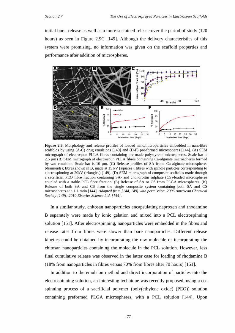
Section 2.7 The Use of Electrosprayed Particles in Electrospun Scaffolds
- 77 -
initial burst release as well as a more sustained release over the period of study (120
hours) as seen in Figure 2.9C [149]. Although the delivery characteristics of this
system were promising, no information was given on the scaffold properties and
performance after addition of microspheres.
Figure 2.9. Morphology and release profiles of loaded nano/microparticles embedded in nanofibre
scaffolds by using (A-C) drug emulsions [149] and (D-F) pre-formed microspheres [144]. (A) SEM
micrograph of electrospun PLLA fibres containing pre-made polystyrene microspheres. Scale bar is
2.5 µm (B) SEM micrograph of electrospun PLLA fibres containing Ca-alginate microspheres formed
by w/o emulsion. Scale bar is 10 µm. (C) Release profiles of SA from: Ca-alginate microspheres
(diamonds); fibres shown in B, made at 15 kV (squares); fibres with spindle particles corresponding to
electrospinning at 20kV (triangles) [149]. (D) SEM micrograph of composite scaffolds made through
a sacrificial PEO fibre fraction containing SA- and chondroitin sulphate (CS)-loaded microspheres
coupled with a stable PCL fibre fraction. (E) Release of SA or CS from PLGA microspheres. (K)
Release of both SA and CS from the single composite system containing both SA and CS
microspheres at a 1:1 ratio [144]. Adapted from [144, 149] with permission. 2006 American Chemical
Society [149]; 2010 Elsevier Science Ltd. [144].
In a similar study, chitosan nanoparticles encapsulating naproxen and rhodamine
B separately were made by ionic gelation and mixed into a PCL electrospinning
solution [151]. After electrospinning, nanoparticles were embedded in the fibres and
release rates from fibres were slower than bare nanoparticles. Different release
kinetics could be obtained by incorporating the raw molecule or incorporating the
chitosan nanoparticles containing the molecule in the PCL solution. However, less
final cumulative release was observed in the latter case for loading of rhodamine B
(18% from nanoparticles in fibres versus 70% from fibres after 70 hours) [151].
In addition to the emulsion method and direct incorporation of particles into the
electrospinning solution, an interesting technique was recently proposed, using a co-
spinning process of a sacrificial polymer (poly(ethylene oxide) (PEO)) solution
containing preformed PLGA microspheres, with a PCL solution [144]. Upon
A C
Cu
mu
lati
ve re
leas
e (%
)
0
100
80
60
40
20
1200 Time (h)40 80
E F
B
D
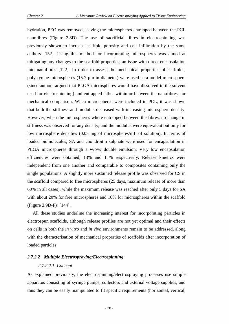
Chapter 2 A Literature Review on Electrospraying Applied to Tissue Engineering
- 78 -
hydration, PEO was removed, leaving the microspheres entrapped between the PCL
nanofibres (Figure 2.8D). The use of sacrificial fibres in electrospinning was
previously shown to increase scaffold porosity and cell infiltration by the same
authors [152]. Using this method for incorporating microspheres was aimed at
mitigating any changes to the scaffold properties, an issue with direct encapsulation
into nanofibres [122]. In order to assess the mechanical properties of scaffolds,
polystyrene microspheres (15.7 µm in diameter) were used as a model microsphere
(since authors argued that PLGA microspheres would have dissolved in the solvent
used for electrospinning) and entrapped either within or between the nanofibres, for
mechanical comparison. When microspheres were included in PCL, it was shown
that both the stiffness and modulus decreased with increasing microsphere density.
However, when the microspheres where entrapped between the fibres, no change in
stiffness was observed for any density, and the modulus were equivalent but only for
low microsphere densities (0.05 mg of microspheres/mL of solution). In terms of
loaded biomolecules, SA and chondroitin sulphate were used for encapsulation in
PLGA microspheres through a w/o/w double emulsion. Very low encapsulation
efficiencies were obtained; 13% and 11% respectively. Release kinetics were
independent from one another and comparable to composites containing only the
single populations. A slightly more sustained release profile was observed for CS in
the scaffold compared to free microspheres (25 days, maximum release of more than
60% in all cases), while the maximum release was reached after only 5 days for SA
with about 20% for free microspheres and 10% for microspheres within the scaffold
(Figure 2.9D-F)) [144].
All these studies underline the increasing interest for incorporating particles in
electrospun scaffolds, although release profiles are not yet optimal and their effects
on cells in both the in vitro and in vivo environments remain to be addressed, along
with the characterisation of mechanical properties of scaffolds after incorporation of
loaded particles.
2.7.2.2 Multiple Electrospraying/Electrospinning
2.7.2.2.1 Concept
As explained previously, the electrospinning/electrospraying processes use simple
apparatus consisting of syringe pumps, collectors and external voltage supplies, and
thus they can be easily manipulated to fit specific requirements (horizontal, vertical,
Section 2.7 The Use of Electrosprayed Particles in Electrospun Scaffolds
- 79 -
or angled setups). For this reason, these apparatus may be easily used in
combination, for the production of composites with an increased number of
properties. Early attempts to electrospray whilst electrospinning consisted of side-by-
side capillaries and a flat collector moving on an x-y stage [153]. Although the
scaffolds yielded were 100 µm in thickness after 45 min, the area of stream
convergence was so small that non-uniform integration was obtained. The authors
attributed this problem to a stream repulsion effect from Coulombic forces, which
they limited by locating the nozzles perpendicular to one another and using a rotating
mandrel translating on its axis. Stream repulsion was minimised and the combination
of rotation and translation of the mandrel target provided an ideal integration of both
components (electrosprayed smooth muscle cells and poly(ester urethane) urea
(PEUU) fibres in this case). Using this configuration, 5 × 5 cm construct sheets
ranging from 300 to 500 nm in thickness were created and scaffold thickness could
be controlled by adjusting polymer flow rate or fabrication time. The authors
concluded that this setup may find other applications in the future as a means to
fabricate more uniform composite scaffolds by electrospinning multiple materials or
introducing drug-laden microspheres between fibres, a setup which has indeed been
used in consecutive years for either multiple electrospinning or simultaneous
electrospraying/electrospinning [153].
2.7.2.2.2 Multiple Electrospinning
Compared with single electrospinning, more versatility in properties can be achieved
with multiple electrospinning. The drug delivery characteristic can indeed be
effectively coupled with desired mechanical properties. This was obtained, for
example, by simultaneously electrospinning PLGA fibres loaded with tetracycline
hydrochloride (TET), for antibacterial activity, with PEUU, that maintained the
required elastomeric properties [154]. The use of a rotating mandrel for collecting
these constructs is the best approach in multiple electrospinning. It allows aligned
fibres, a configuration highly desirable in tissue engineering, since it mimics some of
the fibrous musculoskeletal tissues, like tendons and ligaments. Although fewer
studies on multiple electrospraying/electrospinning are available, they also use a
rotating mandrel collector and most of these studies face similar issues relating to
this mandrel approach.
Chapter 2 A Literature Review on Electrospraying Applied to Tissue Engineering
- 80 -
Fundamentally, the main limitation in aligned fibres obtained by collection onto a
rotating mandrel is the high density fibre packing, since fibres are drawn in parallel
to one another. This becomes an issue for cellular infiltration, where in most cases,
cellular and tissue formation are often limited to the surface of the electrospun
construct, impairing the necessary cell growth within the central architecture of the
construct [30]. The use of a second electrospinning apparatus was proposed for
simultaneous electrospinning of sacrificial fibres that, once they were removed from
the scaffold, conferred an increased porosity, beneficial for cell infiltration, while
maintaining the anisotropy of the scaffold. To this end, PCL and PEO were co-
electrospun onto a rotating mandrel, followed by dissolution of PEO into water after
production (Figure 2.10B) [152]. Importantly, cell infiltration and distribution after
three weeks in culture increased in the starting sacrificial fraction when scaffolds
were seeded with mesenchymal stem cells [152]. On the other hand, limited cell
infiltration was reported when a PCL/collagen blend was co-spun with PEO [155].
Certainly the electrospinning parameters have a great influence in the fibre
deposition and fibre characteristics and must be optimised for effective improvement
in cell infiltration. Another approach to improve cell infiltration was proposed which
involved simultaneously electrospinning microfibres and nanofibres, obtained by
melt and solution electrospinning, respectively (Figure 2.10A). Microfibres increased
the porosity of scaffolds to facilitate cellular infiltration and nanofibres gave an
enhanced effect on cell attachment and growth due to the nanoscale features (Figure
2.10C-E). The so-produced PLGA composite scaffolds provided significantly higher
attachment and spreading of both human epidermal keratinocytes and fibroblasts
(Figure 2.10F-H) [156].
Another drawback of electrospun fibres from synthetic polymers, which may be
overcome by multiple electrospinning, is the lack of biological recognition. For some
applications, however, such as vascular grafts, a cell-responsive surface is
paramount. This has been achieved by simultaneously electrospinning PCL and silk
fibroin, for their respective mechanical and cell-conducive properties, onto a rotating
mandrel, conferring anisotropic properties as well [157]. More than a simple
overlapping of nanofibres, double electrospinning provided a high integration of both
types of fibres and the change of mandrel rotation speed may render the anisotropy
tunable. This may be kept in mind when optimising the electrosprayed/electrospun
constructs.
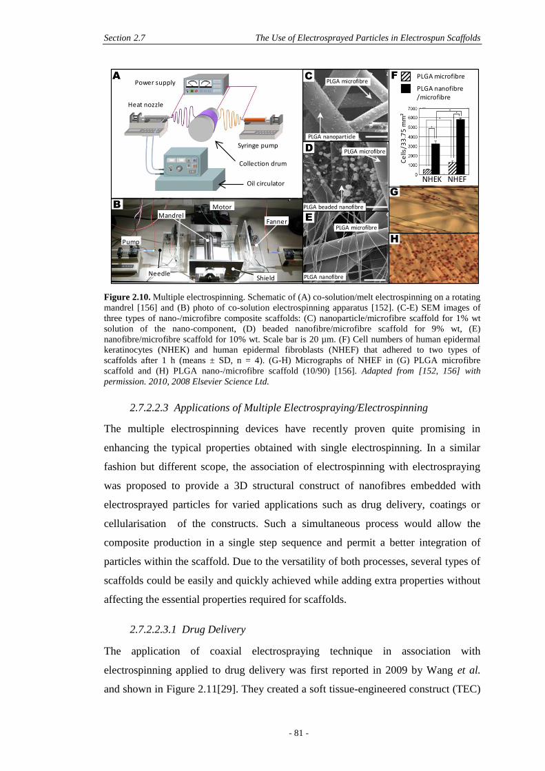
Section 2.7 The Use of Electrosprayed Particles in Electrospun Scaffolds
- 81 -
Figure 2.10. Multiple electrospinning. Schematic of (A) co-solution/melt electrospinning on a rotating
mandrel [156] and (B) photo of co-solution electrospinning apparatus [152]. (C-E) SEM images of
three types of nano-/microfibre composite scaffolds: (C) nanoparticle/microfibre scaffold for 1% wt
solution of the nano-component, (D) beaded nanofibre/microfibre scaffold for 9% wt, (E)
nanofibre/microfibre scaffold for 10% wt. Scale bar is 20 µm. (F) Cell numbers of human epidermal
keratinocytes (NHEK) and human epidermal fibroblasts (NHEF) that adhered to two types of
scaffolds after 1 h (means ± SD, n = 4). (G-H) Micrographs of NHEF in (G) PLGA microfibre
scaffold and (H) PLGA nano-/microfibre scaffold (10/90) [156]. Adapted from [152, 156] with
permission. 2010, 2008 Elsevier Science Ltd.
2.7.2.2.3 Applications of Multiple Electrospraying/Electrospinning
The multiple electrospinning devices have recently proven quite promising in
enhancing the typical properties obtained with single electrospinning. In a similar
fashion but different scope, the association of electrospinning with electrospraying
was proposed to provide a 3D structural construct of nanofibres embedded with
electrosprayed particles for varied applications such as drug delivery, coatings or
cellularisation of the constructs. Such a simultaneous process would allow the
composite production in a single step sequence and permit a better integration of
particles within the scaffold. Due to the versatility of both processes, several types of
scaffolds could be easily and quickly achieved while adding extra properties without
affecting the essential properties required for scaffolds.
2.7.2.2.3.1 Drug Delivery
The application of coaxial electrospraying technique in association with
electrospinning applied to drug delivery was first reported in 2009 by Wang et al.
and shown in Figure 2.11[29]. They created a soft tissue-engineered construct (TEC)
PLGA microfibre
PLGA nanofibre
E
Oil circulator
Heat nozzle
Power supply
Collection drum
Syringe pump
MandrelMotor
Fanner
Pump
NeedleShield
F PLGA microfibre
PLGA nanofibre/microfibre
Ce
lls/3
3.7
5 m
m²
NHEK NHEF
G
PLGA microfibreC
PLGA nanoparticle
H
A
B PLGA beaded nanofibre
D PLGA microfibre
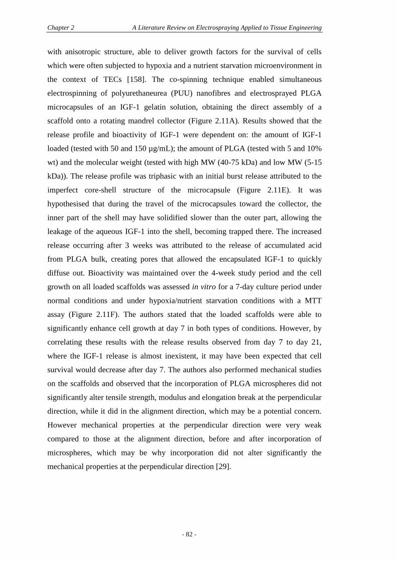
Chapter 2 A Literature Review on Electrospraying Applied to Tissue Engineering
- 82 -
with anisotropic structure, able to deliver growth factors for the survival of cells
which were often subjected to hypoxia and a nutrient starvation microenvironment in
the context of TECs [158]. The co-spinning technique enabled simultaneous
electrospinning of polyurethaneurea (PUU) nanofibres and electrosprayed PLGA
microcapsules of an IGF-1 gelatin solution, obtaining the direct assembly of a
scaffold onto a rotating mandrel collector (Figure 2.11A). Results showed that the
release profile and bioactivity of IGF-1 were dependent on: the amount of IGF-1
loaded (tested with 50 and 150 µg/mL); the amount of PLGA (tested with 5 and 10%
wt) and the molecular weight (tested with high MW (40-75 kDa) and low MW (5-15
kDa)). The release profile was triphasic with an initial burst release attributed to the
imperfect core-shell structure of the microcapsule (Figure 2.11E). It was
hypothesised that during the travel of the microcapsules toward the collector, the
inner part of the shell may have solidified slower than the outer part, allowing the
leakage of the aqueous IGF-1 into the shell, becoming trapped there. The increased
release occurring after 3 weeks was attributed to the release of accumulated acid
from PLGA bulk, creating pores that allowed the encapsulated IGF-1 to quickly
diffuse out. Bioactivity was maintained over the 4-week study period and the cell
growth on all loaded scaffolds was assessed in vitro for a 7-day culture period under
normal conditions and under hypoxia/nutrient starvation conditions with a MTT
assay (Figure 2.11F). The authors stated that the loaded scaffolds were able to
significantly enhance cell growth at day 7 in both types of conditions. However, by
correlating these results with the release results observed from day 7 to day 21,
where the IGF-1 release is almost inexistent, it may have been expected that cell
survival would decrease after day 7. The authors also performed mechanical studies
on the scaffolds and observed that the incorporation of PLGA microspheres did not
significantly alter tensile strength, modulus and elongation break at the perpendicular
direction, while it did in the alignment direction, which may be a potential concern.
However mechanical properties at the perpendicular direction were very weak
compared to those at the alignment direction, before and after incorporation of
microspheres, which may be why incorporation did not alter significantly the
mechanical properties at the perpendicular direction [29].

Section 2.7 The Use of Electrosprayed Particles in Electrospun Scaffolds
- 83 -
Figure 2.11. (A) One-step fabrication of protein loaded microcapsules and nanofibre scaffolds by
simultaneous coaxial electrospraying/electrospinning techniques. (B-D) Structure of the fabricated
microcapsules. FITC-labelled SA was added into the protein solution, and rhodamine-B was loaded
into the PLGA solution before fabrication. The resulting microcapsule showed: (D) a core-shell
structure with (B) protein solution as the core and (C) PLGA as the shell. Scale bars are 2 µm. (E)
IGF-1 release kinetics from scaffolds fabricated with different PLGA concentration and viscosity and
IGF-1 loading at 37°C. (F) Effect of IGF-1 loading on MSC survival under hypoxia/nutrient starvation
conditions. MSCs were cultured for 1 day under normal culture conditions (21% O2, 5% O2, and 20%
fetal calf serum (FCS)) followed by 6 days under hypoxia/nutrient starvation conditions (5% O2, 5%
CO2, and 1% FCS). (G) Surface morphologies of scaffolds embedded with loaded microcapsules.
Abbreviations: HV: 40-75 kDa PLGA, LV: 5-15 kDA PLGA, HV0: scaffolds with no microspheres,
HV5-50: 5% PLGA – 50 µg/mL IGF-1, HV10-50: 10% PLGA – 50 µg/mL IGF-1, HV10-150: 10%
PLGA – 150µg/mL IGF-1, LV10-50: 10% PLGA – 50µg/mL IGF-1. Adapted from [29] with
permission. 2009 American Chemical Society.
2.7.2.2.3.2 Other Applications
Coating
A clear advantage in simultaneous electrospraying and electrospinning can be found
when the application is coating of nanofibres. This is achieved by electrospraying of
hydrogels as well as non-polymeric particles, such as metal oxide nanoparticles,
ceramics, or even cells. Using a simultaneous device for coating was first of all
shown to be more effective as compared to electrospinning and electrospraying in
sequence. In a comparative study, Jaworek et al. assessed the merits of simultaneous
electrospraying during the electrospinning process against electrospraying onto the
same rotating drum after electrospinning was completed and electrospraying onto the
electrospun mat removed from the drum and placed onto a heated table [159]. Metal
0
2
4
6
8
10
12
0 7 14 21 28
HV5-50HV10-50HV10-150LV10-50
14
Cu
mu
lati
ve IG
F-1
co
nce
ntr
atio
n
(ng
/mL)
Release time (days)
E
Gelatin/BSA/IGF-1 solution
PLGA solution
PU solution
Syringe pump A
Syringe pump B
Rotation
Collecting mandrel
Syringe pump C
A
0
20
40
60
80
100
HV10-150 Perc
enta
ge o
f sur
vive
d M
SCs
(% o
f da
y 1v
alue
)
1 day
7 day
HV10-0 (no IGF-1)
F
B C D
G
HV0 HV5-50 HV10-50 LV10-50
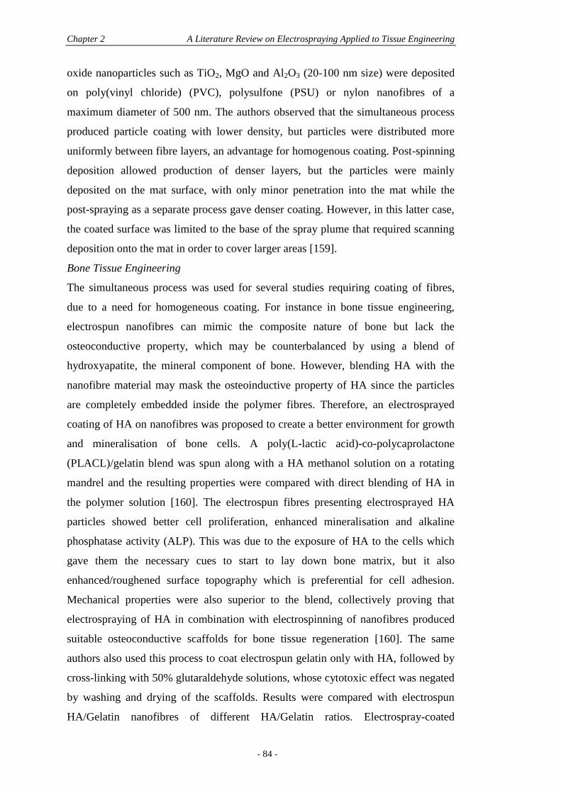
Chapter 2 A Literature Review on Electrospraying Applied to Tissue Engineering
- 84 -
oxide nanoparticles such as TiO2, MgO and Al2O3 (20-100 nm size) were deposited
on poly(vinyl chloride) (PVC), polysulfone (PSU) or nylon nanofibres of a
maximum diameter of 500 nm. The authors observed that the simultaneous process
produced particle coating with lower density, but particles were distributed more
uniformly between fibre layers, an advantage for homogenous coating. Post-spinning
deposition allowed production of denser layers, but the particles were mainly
deposited on the mat surface, with only minor penetration into the mat while the
post-spraying as a separate process gave denser coating. However, in this latter case,
the coated surface was limited to the base of the spray plume that required scanning
deposition onto the mat in order to cover larger areas [159].
Bone Tissue Engineering
The simultaneous process was used for several studies requiring coating of fibres,
due to a need for homogeneous coating. For instance in bone tissue engineering,
electrospun nanofibres can mimic the composite nature of bone but lack the
osteoconductive property, which may be counterbalanced by using a blend of
hydroxyapatite, the mineral component of bone. However, blending HA with the
nanofibre material may mask the osteoinductive property of HA since the particles
are completely embedded inside the polymer fibres. Therefore, an electrosprayed
coating of HA on nanofibres was proposed to create a better environment for growth
and mineralisation of bone cells. A poly(L-lactic acid)-co-polycaprolactone
(PLACL)/gelatin blend was spun along with a HA methanol solution on a rotating
mandrel and the resulting properties were compared with direct blending of HA in
the polymer solution [160]. The electrospun fibres presenting electrosprayed HA
particles showed better cell proliferation, enhanced mineralisation and alkaline
phosphatase activity (ALP). This was due to the exposure of HA to the cells which
gave them the necessary cues to start to lay down bone matrix, but it also
enhanced/roughened surface topography which is preferential for cell adhesion.
Mechanical properties were also superior to the blend, collectively proving that
electrospraying of HA in combination with electrospinning of nanofibres produced
suitable osteoconductive scaffolds for bone tissue regeneration [160]. The same
authors also used this process to coat electrospun gelatin only with HA, followed by
cross-linking with 50% glutaraldehyde solutions, whose cytotoxic effect was negated
by washing and drying of the scaffolds. Results were compared with electrospun
HA/Gelatin nanofibres of different HA/Gelatin ratios. Electrospray-coated
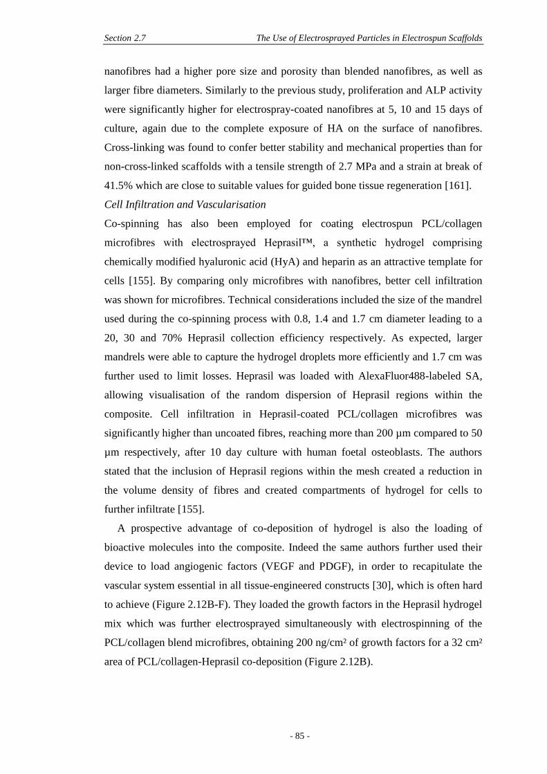
Section 2.7 The Use of Electrosprayed Particles in Electrospun Scaffolds
- 85 -
nanofibres had a higher pore size and porosity than blended nanofibres, as well as
larger fibre diameters. Similarly to the previous study, proliferation and ALP activity
were significantly higher for electrospray-coated nanofibres at 5, 10 and 15 days of
culture, again due to the complete exposure of HA on the surface of nanofibres.
Cross-linking was found to confer better stability and mechanical properties than for
non-cross-linked scaffolds with a tensile strength of 2.7 MPa and a strain at break of
41.5% which are close to suitable values for guided bone tissue regeneration [161].
Cell Infiltration and Vascularisation
Co-spinning has also been employed for coating electrospun PCL/collagen
microfibres with electrosprayed Heprasil™, a synthetic hydrogel comprising
chemically modified hyaluronic acid (HyA) and heparin as an attractive template for
cells [155]. By comparing only microfibres with nanofibres, better cell infiltration
was shown for microfibres. Technical considerations included the size of the mandrel
used during the co-spinning process with 0.8, 1.4 and 1.7 cm diameter leading to a
20, 30 and 70% Heprasil collection efficiency respectively. As expected, larger
mandrels were able to capture the hydrogel droplets more efficiently and 1.7 cm was
further used to limit losses. Heprasil was loaded with AlexaFluor488-labeled SA,
allowing visualisation of the random dispersion of Heprasil regions within the
composite. Cell infiltration in Heprasil-coated PCL/collagen microfibres was
significantly higher than uncoated fibres, reaching more than 200 µm compared to 50
µm respectively, after 10 day culture with human foetal osteoblasts. The authors
stated that the inclusion of Heprasil regions within the mesh created a reduction in
the volume density of fibres and created compartments of hydrogel for cells to
further infiltrate [155].
A prospective advantage of co-deposition of hydrogel is also the loading of
bioactive molecules into the composite. Indeed the same authors further used their
device to load angiogenic factors (VEGF and PDGF), in order to recapitulate the
vascular system essential in all tissue-engineered constructs [30], which is often hard
to achieve (Figure 2.12B-F). They loaded the growth factors in the Heprasil hydrogel
mix which was further electrosprayed simultaneously with electrospinning of the
PCL/collagen blend microfibres, obtaining 200 ng/cm² of growth factors for a 32 cm²
area of PCL/collagen-Heprasil co-deposition (Figure 2.12B).
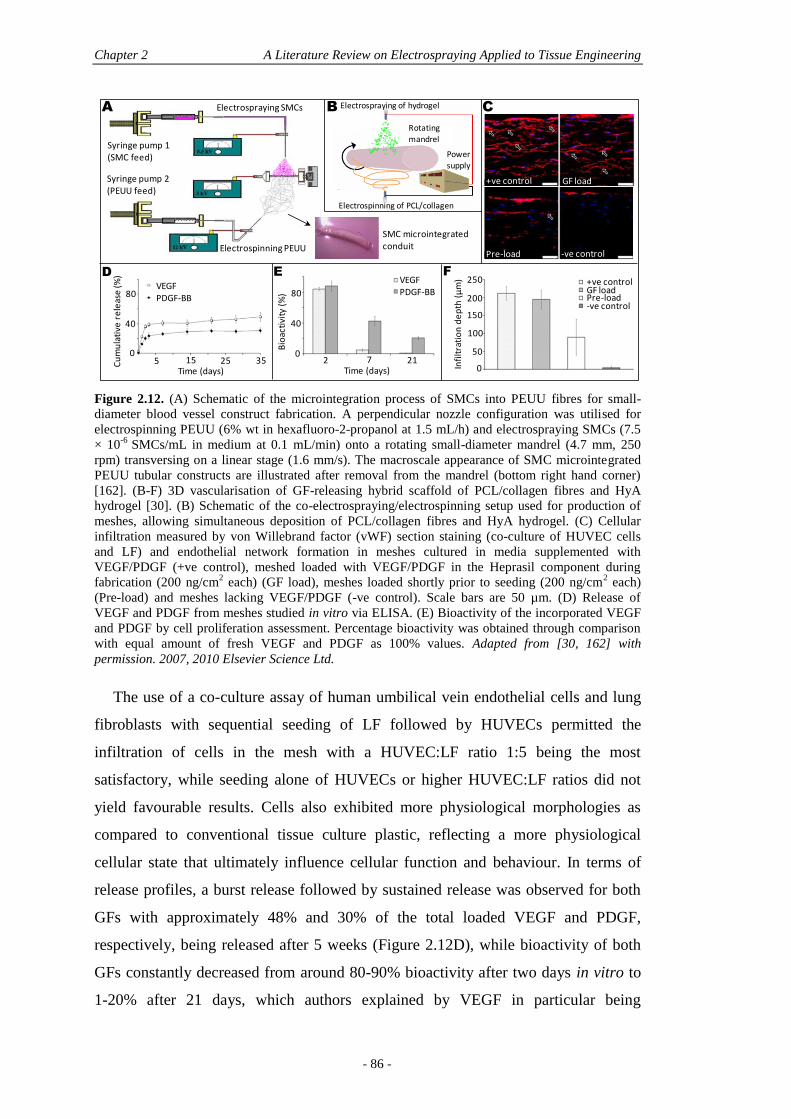
Chapter 2 A Literature Review on Electrospraying Applied to Tissue Engineering
- 86 -
Figure 2.12. (A) Schematic of the microintegration process of SMCs into PEUU fibres for small-
diameter blood vessel construct fabrication. A perpendicular nozzle configuration was utilised for
electrospinning PEUU (6% wt in hexafluoro-2-propanol at 1.5 mL/h) and electrospraying SMCs (7.5
× 10-6
SMCs/mL in medium at 0.1 mL/min) onto a rotating small-diameter mandrel (4.7 mm, 250
rpm) transversing on a linear stage (1.6 mm/s). The macroscale appearance of SMC microintegrated
PEUU tubular constructs are illustrated after removal from the mandrel (bottom right hand corner) [162]. (B-F) 3D vascularisation of GF-releasing hybrid scaffold of PCL/collagen fibres and HyA
hydrogel [30]. (B) Schematic of the co-electrospraying/electrospinning setup used for production of
meshes, allowing simultaneous deposition of PCL/collagen fibres and HyA hydrogel. (C) Cellular
infiltration measured by von Willebrand factor (vWF) section staining (co-culture of HUVEC cells
and LF) and endothelial network formation in meshes cultured in media supplemented with
VEGF/PDGF (+ve control), meshed loaded with VEGF/PDGF in the Heprasil component during
fabrication (200 ng/cm2 each) (GF load), meshes loaded shortly prior to seeding (200 ng/cm
2 each)
(Pre-load) and meshes lacking VEGF/PDGF (-ve control). Scale bars are 50 µm. (D) Release of
VEGF and PDGF from meshes studied in vitro via ELISA. (E) Bioactivity of the incorporated VEGF
and PDGF by cell proliferation assessment. Percentage bioactivity was obtained through comparison
with equal amount of fresh VEGF and PDGF as 100% values. Adapted from [30, 162] with
permission. 2007, 2010 Elsevier Science Ltd.
The use of a co-culture assay of human umbilical vein endothelial cells and lung
fibroblasts with sequential seeding of LF followed by HUVECs permitted the
infiltration of cells in the mesh with a HUVEC:LF ratio 1:5 being the most
satisfactory, while seeding alone of HUVECs or higher HUVEC:LF ratios did not
yield favourable results. Cells also exhibited more physiological morphologies as
compared to conventional tissue culture plastic, reflecting a more physiological
cellular state that ultimately influence cellular function and behaviour. In terms of
release profiles, a burst release followed by sustained release was observed for both
GFs with approximately 48% and 30% of the total loaded VEGF and PDGF,
respectively, being released after 5 weeks (Figure 2.12D), while bioactivity of both
GFs constantly decreased from around 80-90% bioactivity after two days in vitro to
1-20% after 21 days, which authors explained by VEGF in particular being
Syringe pump 1 (SMC feed)
Syringe pump 2 (PEUU feed)
Electrospraying SMCs
Electrospinning PEUU
SMC microintegratedconduit
A B
Electrospinning of PCL/collagen
Electrospraying of hydrogel
Rotating mandrel
Power supply
D E F
Infi
ltra
tio
n d
ep
th (
µm
)
0
50
100
150
200
250 +ve controlGF loadPre-load-ve control
+ve control GF load
Pre-load -ve control
CC
um
ula
tive
re
leas
e (%
)
VEGFPDGF-BB
0
40
80
5 15 25Time (days)
35Time (days)
2 7 21
Bio
acti
vity
(%
)
0
80
40
VEGFPDGF-BB
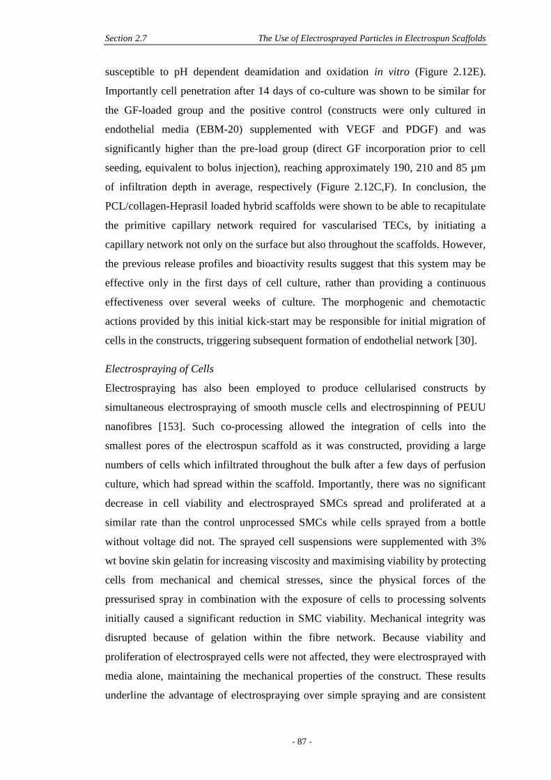
Section 2.7 The Use of Electrosprayed Particles in Electrospun Scaffolds
- 87 -
susceptible to pH dependent deamidation and oxidation in vitro (Figure 2.12E).
Importantly cell penetration after 14 days of co-culture was shown to be similar for
the GF-loaded group and the positive control (constructs were only cultured in
endothelial media (EBM-20) supplemented with VEGF and PDGF) and was
significantly higher than the pre-load group (direct GF incorporation prior to cell
seeding, equivalent to bolus injection), reaching approximately 190, 210 and 85 µm
of infiltration depth in average, respectively (Figure 2.12C,F). In conclusion, the
PCL/collagen-Heprasil loaded hybrid scaffolds were shown to be able to recapitulate
the primitive capillary network required for vascularised TECs, by initiating a
capillary network not only on the surface but also throughout the scaffolds. However,
the previous release profiles and bioactivity results suggest that this system may be
effective only in the first days of cell culture, rather than providing a continuous
effectiveness over several weeks of culture. The morphogenic and chemotactic
actions provided by this initial kick-start may be responsible for initial migration of
cells in the constructs, triggering subsequent formation of endothelial network [30].
Electrospraying of Cells
Electrospraying has also been employed to produce cellularised constructs by
simultaneous electrospraying of smooth muscle cells and electrospinning of PEUU
nanofibres [153]. Such co-processing allowed the integration of cells into the
smallest pores of the electrospun scaffold as it was constructed, providing a large
numbers of cells which infiltrated throughout the bulk after a few days of perfusion
culture, which had spread within the scaffold. Importantly, there was no significant
decrease in cell viability and electrosprayed SMCs spread and proliferated at a
similar rate than the control unprocessed SMCs while cells sprayed from a bottle
without voltage did not. The sprayed cell suspensions were supplemented with 3%
wt bovine skin gelatin for increasing viscosity and maximising viability by protecting
cells from mechanical and chemical stresses, since the physical forces of the
pressurised spray in combination with the exposure of cells to processing solvents
initially caused a significant reduction in SMC viability. Mechanical integrity was
disrupted because of gelation within the fibre network. Because viability and
proliferation of electrosprayed cells were not affected, they were electrosprayed with
media alone, maintaining the mechanical properties of the construct. These results
underline the advantage of electrospraying over simple spraying and are consistent
Chapter 2 A Literature Review on Electrospraying Applied to Tissue Engineering
- 88 -
with literature stating that cells can survive exposure to high voltage [153].
Importantly, the SMC-integrated PEUU composites presented lower tensile strengths
and higher breaking strains, which were explained by the cells disrupting the PEUU
fibre network and replacing elastic PEUU volume with cellular volume. The authors
still concluded that the measured properties were still more than sufficient for the
SMC-integrated PEUU composites to serve as a support structure for soft tissue
growth and mechanical training.
Following these encouraging results, the same authors extended their process to
the fabrication of small-diameter tubular conduits that possess mechanical properties
similar to native blood vessels, after only a few days in culture (Figure 2.12A) [162].
A 4.7 mm diameter mandrel was used in place of the previously employed 19 mm
for sheets [153]. Interestingly they decreased the TTC distance from 5.0 to 4.5 cm
and lowered the mandrel negative charge from -10 to -3 kV to obtain reproducible
and defect free small-diameter tubular constructs. SMC integration was uniform
radially and circumferentially within the conduits after initial static culture, while
conduits were strong and flexible with mechanical properties that mimicked those of
native arteries. Cultures of such cell-based scaffolds are recommended to be
performed in spinner flasks or perfusion rather than static, since in both cases they
led to much higher viable cells and enhanced spreading within the electrospun fibres
[153, 162].
In 2008, mention of simultaneous electrospraying of chondrocytes and
electrospinning of PCL was made in a review by Wu et al. [94]. They stated that
confocal microscopy was used to visualise the living cells embedded in the fibres
after being cultured in the cell media for a set time not mentioned. They also stated
that the experimental results revealed that 80% of the cells were still viable after the
electrohydrodynamic process, while no more information than this was provided (no
description of materials or methods).
Although the futility of the last study, electrospraying of cells with simultaneous
electrospinning of a polymer matrix remains an efficient and rapid method for the
production of tissue-engineered constructs. However, this is by no means a trivial
and straight forward procedure and issues of sterility and time required to produce
thicker scaffolds may potentially limit this application [152].
Section 2.8 Conclusions
- 89 -
2.8 CONCLUSIONS
The controlled and targeted delivery of therapeutic molecules is tantamount to the
success of many medical treatments. With the development of superior treatment
options for cancer, asthma and hormonal therapies there is a concomitant demand to
encapsulate and release the active molecules in a safe, reproducible and effective
manner.
The technique of electrospraying has emerged as a promising technology to
produce particles with entrapped therapeutic molecules which may be released as
the particle degrades. The size and morphology of the particles produced are of
paramount importance to enable batch-to-batch reproducibility and appropriate
efficacy of the system. We have reviewed the many variables and interplays of the
processing parameters which affect the production of microparticles and have
highlighted the shortfalls associated with many current technologies. Importantly we
have also highlighted the need to thoroughly assess and publish the encapsulation
efficiencies, bioactivity and denaturation of the encapsulated biomolecules, both in
vitro and in vivo. Only when all of these considerations are properly tackled can
a delivery system for the use in targeted biomolecule delivery - for example in tissue
engineering, be properly realised and translated to the clinic.
2.9 ACKNOWLEDGEMENTS
Thanks to Dr. Tristan Croll from the Tissue Repair and Regeneration program for
molecule designing, Jaime Nakahara for proof-reading and to the Biomaterials and
Tissue Morphology group, Tissue Repair and Regeneration program, Regenerative
Medicine group, IHBI and the Australian Research Council (ARC) (Discovery grant
no. DP0989000) for financial support.

- 91 -
Chapter 3: Electrospraying, a Reproducible
Method for Production of Polymeric
Microspheres for Biomedical
Applications
Nathalie Bock1,2,3
, Maria A. Woodruff1, Dietmar W. Hutmacher
2, Tim R.
Dargaville3
Published in Polymers, Volume 3, Issue 1, 2010, Pages 131-149.
© 2010 by the authors; licensee MDPI, Basel, Switzerland.
Statement of contribution of co-authors for thesis by published papers
Contributors Statement of contribution
Nathalie Bock Developed the research questions
Designed and performed the experiments
Analysed and interpreted the results
Conceived and wrote the manuscript
Maria A. Woodruff* Involved in the conception of the project
Provided feedback on manuscript
Dietmar W. Hutmacher* Involved in the conception of the project
Provided feedback on manuscript
Tim R. Dargaville* Involved in the conception of the project
Assisted with thermal characterisation
Provided feedback on manuscript
1 Biomaterials and Tissue Morphology Group
2 Regenerative Medicine Group
3 Tissue Repair and Regeneration Group
Institute of Health and Biomedical Innovation, Queensland University of Technology,
60 Musk Avenue, Kelvin Grove, QLD 4059, Australia
Chapter 3 Reproducible Polymeric Microspheres by Electrospraying
- 92 -
The authors listed above have certified* that:
1. they meet the criteria for authorship in that they have participated in the
conception, execution, or interpretation, of at least that part of the publication in
their field of expertise;
2. they take public responsibility for their part of the publication, except for the
responsible author who accepts overall responsibility for the publication;
3. there are no other authors of the publication according to these criteria;
4. potential conflicts of interest have been disclosed to (a) granting bodies, (b) the
editor or publisher of journals or other publications, and (c) the head of the
responsible academic unit, and
5. they agree to the use of the publication in the student’s thesis and its publication
on the QUT ePrints database consistent with any limitations set by publisher
requirements.
Principal Supervisor Confirmation
I have sighted email or other correspondence from all Co-authors confirming their
certifying authorship.
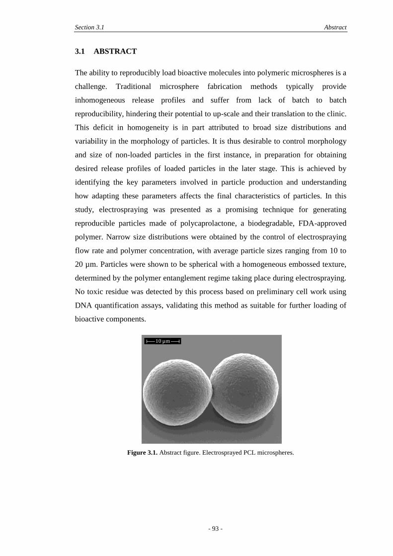
Section 3.1 Abstract
- 93 -
3.1 ABSTRACT
The ability to reproducibly load bioactive molecules into polymeric microspheres is a
challenge. Traditional microsphere fabrication methods typically provide
inhomogeneous release profiles and suffer from lack of batch to batch
reproducibility, hindering their potential to up-scale and their translation to the clinic.
This deficit in homogeneity is in part attributed to broad size distributions and
variability in the morphology of particles. It is thus desirable to control morphology
and size of non-loaded particles in the first instance, in preparation for obtaining
desired release profiles of loaded particles in the later stage. This is achieved by
identifying the key parameters involved in particle production and understanding
how adapting these parameters affects the final characteristics of particles. In this
study, electrospraying was presented as a promising technique for generating
reproducible particles made of polycaprolactone, a biodegradable, FDA-approved
polymer. Narrow size distributions were obtained by the control of electrospraying
flow rate and polymer concentration, with average particle sizes ranging from 10 to
20 µm. Particles were shown to be spherical with a homogeneous embossed texture,
determined by the polymer entanglement regime taking place during electrospraying.
No toxic residue was detected by this process based on preliminary cell work using
DNA quantification assays, validating this method as suitable for further loading of
bioactive components.
Figure 3.1. Abstract figure. Electrosprayed PCL microspheres.
10 µm
Chapter 3 Reproducible Polymeric Microspheres by Electrospraying
- 94 -
3.2 KEYWORDS
Electrospraying, drug delivery, microspheres, polycaprolactone.
3.3 INTRODUCTION
The use of polymeric particles has been of great interest in the biomedical field for
the last 50 years, with a particular niche present in the field of drug delivery [18,
163]. Current technologies allow the production of biodegradable nano- and micro-
sized materials able to encapsulate therapeutic molecules to be gradually released
through diffusion and degradation in vivo. The motivation behind this process is the
possibility to overcome the limitations faced in bolus delivery of molecules,
especially proteins where the harsh in vivo environment can cause denaturation,
shortening their half-life after delivery, and thus reducing action efficacy [35].
Polymeric particles are therefore presented as reservoir systems able to protect the
proteins from their environment, enhancing their long-term biological activity.
Ideally, these systems are also able to provide tailored release rates, required by
certain therapies, by the control of particle morphology, size and polymeric matrix
[17]. Importantly, such particles have the potential to minimise the propagation of
drug payloads to non-targeted areas, limiting unwanted effects and allowing a site-
specific delivery [18, 35, 40, 163].
Several techniques have been presented in the literature for fabrication of
polymeric nano- and microparticles, the most popular being based on emulsion
techniques [40, 84, 120, 126, 164, 165]. Molecules are dispersed or dissolved into a
polymer solution and emulsified to form micro-droplets that are further dried after
solvent removal [26]. However, the use of organic solvents, unless carefully
controlled, is a drawback in many of these techniques since it can lead to
denaturation of protein-based drugs during processing, increasing the variability in
encapsulation efficiencies and loading capacities [126]. Secondly, the size
distributions of particles fabricated by emulsion-based techniques tend to be
inhomogeneous and broad, contributing to their lack of reproducibility, which in turn
hinders their clinical use. Size distribution is a crucial parameter and it was shown
that monodisperse size would enable a better control of release profiles and
bioavailability of the loaded drug in the body [59, 64]. Particle morphology is also
important since it affects the internalisation by non-phagocytic cells and the
Section 3.3 Introduction
- 95 -
degradation of the polymer matrix which, in turn, determines the release kinetics of
the loaded component. Therefore, homogeneity of morphology is also an important
consideration to ensure particles with reproducible characteristics are obtained.
Fabrication of polymer microparticles by electrospraying has the potential to
overcome the limitations of emulsion-based techniques and to provide reproducibly
loaded nano- and microparticles [51]. Electrospraying is a one-step technique which
has potential to generate narrow size distributions of submicrometric particles, with
limited agglomeration of particles and high yields [97]. The principles of
electrospraying are based on the ability of an electric field to deform the interface of
a liquid drop, established by Lord Rayleigh in 1882 [75], further developed by
Zeleny in 1917 [166] and Sir Taylor in 1964 [167]. The theory of charged droplets
states that if an electrified field is applied to any droplet, the electric charge generates
an electrostatic force inside the droplet, known as the Coulomb force, which
competes with the cohesive force intrinsic to the droplet. When the applied Coulomb
force is able to overcome the cohesive force of the droplet manifested in the surface
tension, the droplet will undergo breakup into smaller droplets in the micro- to nano-
scales. This phenomenon begins at the Taylor Cone, referring to the progressive
shrinkage of the unstable, charged macro-droplet into a cone from which the smaller
charged droplets will be ejected as soon as the surface tension is overcome by the
Coulomb force. Once the charged droplet is in flight towards the collector, Rayleigh
predicted a limit where subsequent break-up of the droplet may occur, called the
Rayleigh limit, LR, expressed in Equation 3.1:
( ) (3.1)
Droplet break-up is also known as Coulomb fission and is an unwanted
phenomenon in monodisperse electrospraying, since it generates bimodal size
distributions [49, 52, 110, 168, 169]. LR is a function of q the surface charge of the
droplet, ε the permittivity of the surrounding medium, γ the surface tension of the
liquid and R the radius of the droplet. The maximum surface charge of the droplet is
given by Equation 3.2:
√ (3.2)
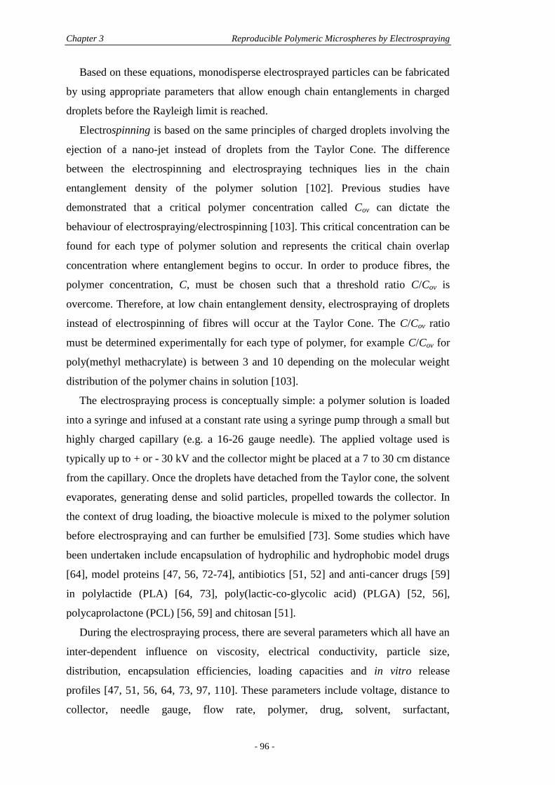
Chapter 3 Reproducible Polymeric Microspheres by Electrospraying
- 96 -
Based on these equations, monodisperse electrosprayed particles can be fabricated
by using appropriate parameters that allow enough chain entanglements in charged
droplets before the Rayleigh limit is reached.
Electrospinning is based on the same principles of charged droplets involving the
ejection of a nano-jet instead of droplets from the Taylor Cone. The difference
between the electrospinning and electrospraying techniques lies in the chain
entanglement density of the polymer solution [102]. Previous studies have
demonstrated that a critical polymer concentration called Cov can dictate the
behaviour of electrospraying/electrospinning [103]. This critical concentration can be
found for each type of polymer solution and represents the critical chain overlap
concentration where entanglement begins to occur. In order to produce fibres, the
polymer concentration, C, must be chosen such that a threshold ratio C/Cov is
overcome. Therefore, at low chain entanglement density, electrospraying of droplets
instead of electrospinning of fibres will occur at the Taylor Cone. The C/Cov ratio
must be determined experimentally for each type of polymer, for example C/Cov for
poly(methyl methacrylate) is between 3 and 10 depending on the molecular weight
distribution of the polymer chains in solution [103].
The electrospraying process is conceptually simple: a polymer solution is loaded
into a syringe and infused at a constant rate using a syringe pump through a small but
highly charged capillary (e.g. a 16-26 gauge needle). The applied voltage used is
typically up to + or - 30 kV and the collector might be placed at a 7 to 30 cm distance
from the capillary. Once the droplets have detached from the Taylor cone, the solvent
evaporates, generating dense and solid particles, propelled towards the collector. In
the context of drug loading, the bioactive molecule is mixed to the polymer solution
before electrospraying and can further be emulsified [73]. Some studies which have
been undertaken include encapsulation of hydrophilic and hydrophobic model drugs
[64], model proteins [47, 56, 72-74], antibiotics [51, 52] and anti-cancer drugs [59]
in polylactide (PLA) [64, 73], poly(lactic-co-glycolic acid) (PLGA) [52, 56],
polycaprolactone (PCL) [56, 59] and chitosan [51].
During the electrospraying process, there are several parameters which all have an
inter-dependent influence on viscosity, electrical conductivity, particle size,
distribution, encapsulation efficiencies, loading capacities and in vitro release
profiles [47, 51, 56, 64, 73, 97, 110]. These parameters include voltage, distance to
collector, needle gauge, flow rate, polymer, drug, solvent, surfactant,
Section 3.3 Introduction
- 97 -
protein/polymer ratio and organic/aqueous ratio. As a consequence, although
electrospraying is a promising technique, the number of parameters to be used can
render its optimisation highly complex. The characteristics of electrosprayed
particles are still not completely understood and it is important to proceed in a step-
wise manner intended to understand the relationship between processing parameters
and characteristics of electrosprayed microparticles before one progresses to the
inclusion of highly fragile and expensive bioactive molecules. This study details the
reproducibility of the process and identifies the key parameters responsible for
particle size, distribution and morphology as a prelude to using the validated
methodologies for the loading of a bioactive molecule.
Previous studies have correlated the effects of key variables of electrospraying
[49, 52, 110, 168, 169]. Most of these studies are PLGA-based, which are well-
known as the most common biodegradable and FDA-approved polymers in tissue
engineering literature. However, in the context of drug delivery for orthopaedic
applications, a slower degrading polymer like polycaprolactone should be
considered. PCL is also FDA-approved and various drugs have been encapsulated in
PCL microspheres and nanospheres [88, 90]. PCL is highly permeable to small drug
molecules and degrades through its ester linkages. As compared to PLGA-based
polymers, it also presents the advantage of a lesser acidic environment being
generated during degradation [90], however, only very few studies have investigated
the production of electrosprayed PCL particles [71, 80, 98]. As aforementioned, the
type of polymer will give different characteristics of electrosprayed particles and due
to the complexity and inter-dependence of variables involved in the process, PLGA
production parameters might not be translatable to PCL. The objective of this study
was therefore to study the morphology and particle size obtained for non-loaded
electrosprayed PCL microspheres and to ensure their reproducibility. Importantly,
the toxicity of so-produced microspheres was assessed in order to ensure that no
toxic residue remained after electrospraying. These are essential steps to be validated
and understood before progressing to protein loading.
Chapter 3 Reproducible Polymeric Microspheres by Electrospraying
- 98 -
3.4 EXPERIMENTAL SECTION
3.4.1 Materials
Polycaprolactone, Mn = 84 kDa (Perstorp Ltd, UK - Capa® 6500C) was used to
produce the microspheres. Ultra-pure chloroform (99.0-99.4%) from Merck,
Germany was used to dissolve PCL. Different concentrations were prepared: 5, 7.5, 9
and 10% wt/v (i.e. for 10% wt/v, 10 g of PCL were dissolved in chloroform and
made up to 100 mL total volume). The polymer solutions were magnetically stirred
for 3 hours at room temperature to allow complete dissolution before
electrospraying.
3.4.2 Microsphere Production
Figure 3.2A shows a typical schematic of the electrospraying setup used to produce
the microspheres. Initially, the electrospraying parameters chosen in this work were
based on previous studies on optimisation of electrosprayed particles [49, 52, 58, 97,
98, 100, 110, 168, 169]. Temperature and relative humidity ranged from 22 to 24°C,
and 44 to 49% respectively. Collectors were made of standard aluminium foils (20 ×
20 cm2). PCL solutions were loaded in a 2.5 mL glass syringe (Hamilton, USA)
fitted with a 21 or 26-gauge stainless steel nozzle (Terumo, Japan and Becton
Dickinson, USA). PCL solutions were extruded through the nozzle at a constant rate
of either 0.2 or 0.5 mL/h using a syringe pump (WPI, USA). The tip-to-collector
(TTC) distance was set to 15, 20 or 25 cm respectively. High-voltage was applied
between the needle and collector ranging from 10 to 18 kV. After electrospraying,
the collectors were placed under vacuum for a further 72 hours, to remove any
chloroform residue from microspheres. The microspheres were then transferred into
glass vials and further evacuated for storage. The different experimental parameters
employed are summarised in Table 3.1. The microspheres produced under each set of
parameters are abbreviated as M, with a number referring to the condition type (a set
of parameters). For example: for condition 1, the produced microspheres are M1-
type.
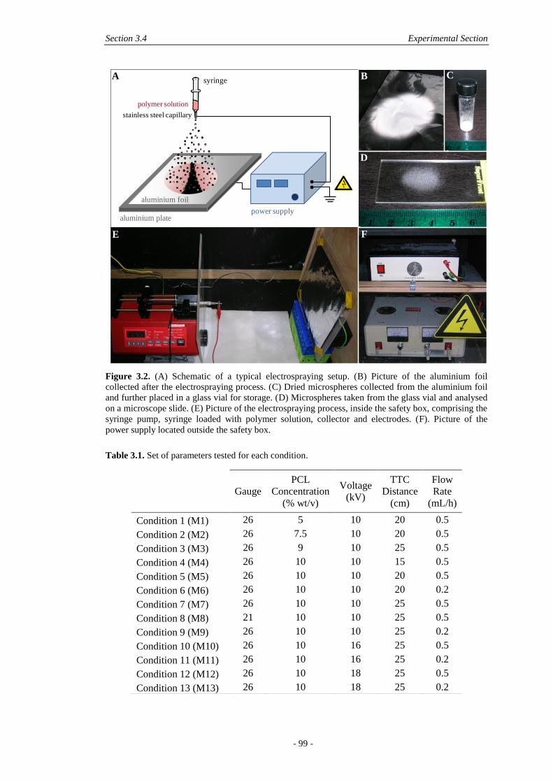
Section 3.4 Experimental Section
- 99 -
Figure 3.2. (A) Schematic of a typical electrospraying setup. (B) Picture of the aluminium foil
collected after the electrospraying process. (C) Dried microspheres collected from the aluminium foil
and further placed in a glass vial for storage. (D) Microspheres taken from the glass vial and analysed
on a microscope slide. (E) Picture of the electrospraying process, inside the safety box, comprising the
syringe pump, syringe loaded with polymer solution, collector and electrodes. (F). Picture of the
power supply located outside the safety box.
Table 3.1. Set of parameters tested for each condition.
polymer solution
aluminium foil
power supply
syringe
stainless steel capillary
aluminium plate
A B C
D
E F
Gauge
PCL
Concentration
(% wt/v)
Voltage
(kV)
TTC
Distance
(cm)
Flow
Rate
(mL/h)
Condition 1 (M1) 26 5 10 20 0.5
Condition 2 (M2) 26 7.5 10 20 0.5
Condition 3 (M3) 26 9 10 25 0.5
Condition 4 (M4) 26 10 10 15 0.5
Condition 5 (M5) 26 10 10 20 0.5
Condition 6 (M6) 26 10 10 20 0.2
Condition 7 (M7) 26 10 10 25 0.5
Condition 8 (M8) 21 10 10 25 0.5
Condition 9 (M9) 26 10 10 25 0.2
Condition 10 (M10) 26 10 16 25 0.5
Condition 11 (M11) 26 10 16 25 0.2
Condition 12 (M12) 26 10 18 25 0.5
Condition 13 (M13) 26 10 18 25 0.2
Chapter 3 Reproducible Polymeric Microspheres by Electrospraying
- 100 -
3.4.3 Physical Characterisation
The morphology and microstructure of electrosprayed microspheres were
characterised with a scanning electron microscope (FEI Quanta 200 SEM) operating
at 10 kV. Micrographs were taken from low and high magnifications, in order to
have overviews of batches and detailed morphology of microspheres respectively.
Microspheres were imaged directly on the microscope slides used for particle size
determination, or after collection from the aluminium foil. In the latter case, particles
were carefully deposited on carbon sticky tape, previously mounted on aluminium
stubs. Both microscope slides and stubs were gold sputtered (BIORAD SC-500
Sputter coater) for 75 s at 30 mA before imaging.
In order to determine particle size of electrosprayed microspheres, a microscope
glass slide was introduced in the electrospraying box and held in contact with the
collector, in the centre of the spraying zone for 5 minutes. The slide was then
removed and analysed by light microscopy (AxoVision, Carl Zeiss MicroImaging
GmbH, Germany). In order to assess the reproducibility of electrospraying, 3
replicates of each condition were generated. Voltage was turned off between
replicates. Particle size was assessed with Image J analysis software (NIH) based on
the micrographs. The results were plotted as box plots and expressed in medians,
with n = 100-1,000 for each replicate, whereas size distribution was shown for all
values obtained per condition.
Electrosprayed particles (M3-type) and unprocessed pellets were characterised by
differential scanning calorimetry (TA Instruments Q100 DSC) by scanning from
0°C 110°C 0°C with a heating and cooling rate of 10°C/min. The initial run
was followed by a repeat run with the thermal history erased.
3.4.4 Biological Effect of Microspheres
The effect of electrosprayed microspheres on cells was assessed by two methods: the
extraction method and direct contact method as per ISO 10993-12. The extraction
method, also known as the elution method, required an extract from the material to
be tested. The extract was placed on a near-confluent monolayer of fibroblast cells
and toxicity was evaluated by observing cell numbers using DNA measures. M3-type
microspheres were used for this experiment, UV sterilised for 40 minutes
immediately before the assay. 0.1 and 1% wt/v of microspheres were placed in
completed Dulbecco's modified Eagle medium (DMEM) (10% foetal calf serum, 1%
Section 3.5 Results and Discussion
- 101 -
penicillin/streptomycin) for 1 and 24 h. The extract solutions were further removed,
filtered and seeded on cells. For the direct contact method, 0.01 and 0.1% wt/v M3-
type microspheres were rinsed in media for 15 minutes and 1 hour, before being
placed on the near-confluent monolayer of fibroblast cells, or left non-rinsed but
incubated for the same amount of time (37°C, 5% C02). In both methods, NIH3T3
cells were cultured for 24 h before exposure to the test solutions for another 48 h
(initial seeding density: 3 × 10⁴ cells). DNA quantification was determined using
CyQUANT® (Invitrogen) (n = 4). Results were expressed in normalised averages ±
standard errors (SE).
3.5 RESULTS AND DISCUSSION
3.5.1 Physical Characterisation
3.5.1.1 Morphology
Electrospraying resulted in either microspheres or flattened particles, both with
textured surfaces. The spherical morphology was obtained only for high polymer
concentrations (9 and 10% wt/v), while flattened morphology and coalescence
between particles was observed for decreased polymer concentrations (5 and 7.5%
wt/v) (Figure 3.3). These results are in accordance with previous studies, where
polymer concentration was often shown to be the most critical parameter in the
morphology of electrosprayed particles [98].
The generation of electrosprayed particles is widely accepted to be controlled by
two main mechanisms: solvent evaporation from droplets en route from the tip to the
collector, and contemporaneous polymer diffusion during evaporation [49]. Rapid
polymer diffusion does not necessarily lead to spherical particles but will ensure
solid, dense particles. Both these mechanisms are dictated by the characteristics of
the electrosprayed polymer solution itself, dependent on molecular weight and
polymer concentration. For conditions 1 and 2 (Table 3.1) for instance, the polymer
solutions are only 5 and 7.5% wt/v, respectively and lead to the flattened morphology
shown in Figure 3.3A-B, rather than a spherical morphology, observed at higher
polymer concentrations (9 and 10% wt/v) as shown in Figure 3.3C-D. The flattened
morphology is even more pronounced for the 5% wt/v particles rather than the 7.5%
wt/v particles, indicating that lower polymer concentration favours the formation of
flat particles instead of spheres. These two cases are a direct consequence of
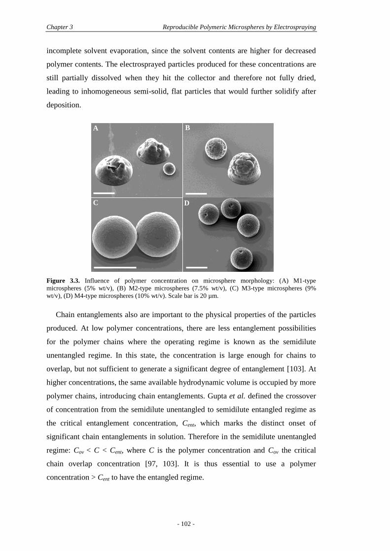
Chapter 3 Reproducible Polymeric Microspheres by Electrospraying
- 102 -
incomplete solvent evaporation, since the solvent contents are higher for decreased
polymer contents. The electrosprayed particles produced for these concentrations are
still partially dissolved when they hit the collector and therefore not fully dried,
leading to inhomogeneous semi-solid, flat particles that would further solidify after
deposition.
Figure 3.3. Influence of polymer concentration on microsphere morphology: (A) M1-type
microspheres (5% wt/v), (B) M2-type microspheres (7.5% wt/v), (C) M3-type microspheres (9%
wt/v), (D) M4-type microspheres (10% wt/v). Scale bar is 20 µm.
Chain entanglements also are important to the physical properties of the particles
produced. At low polymer concentrations, there are less entanglement possibilities
for the polymer chains where the operating regime is known as the semidilute
unentangled regime. In this state, the concentration is large enough for chains to
overlap, but not sufficient to generate a significant degree of entanglement [103]. At
higher concentrations, the same available hydrodynamic volume is occupied by more
polymer chains, introducing chain entanglements. Gupta et al. defined the crossover
of concentration from the semidilute unentangled to semidilute entangled regime as
the critical entanglement concentration, Cent, which marks the distinct onset of
significant chain entanglements in solution. Therefore in the semidilute unentangled
regime: Cov < C < Cent, where C is the polymer concentration and Cov the critical
chain overlap concentration [97, 103]. It is thus essential to use a polymer
concentration > Cent to have the entangled regime.
A B
C D
Section 3.5 Results and Discussion
- 103 -
Reproducibility of electrosprayed particles is a problem when working in the
semidilute unentangled regime where entanglements are less frequent. In order to
obtain reproducible, homogeneous, and solid particles, it is necessary to ensure
complete solvent removal and to use polymer concentrations above Cent. This is
equally important for producing spherical particles as it was shown that if the
evaporating droplets present a sufficiently entangled network before they reach the
Rayleigh limit, the resulting particles will remain monodisperse and spherical, as the
entangled network stabilises the droplet against rupture, reducing the frequency of
smaller offspring particles being emitted [49]. There are some scaling laws to
determine Cent for each type of polymer solution, however it is most likely to be
determined experimentally. In the case of PCL 84 kDa dissolved in chloroform, it
can be deducted from this study that Cent is comprised between 7.5 and 10% wt/v,
where 10% wt/v was sufficient to produce solid particles on the collector, ensuring
homogeneity and sphericity of particles.
The texture observed for spherical particles was previously described as an
‘embossing golf-ball structure of the colloidal surface’ [80]. Another study on the
effect of the solvent properties on electrosprayed polymer particles described how
the morphology can be changed according to the type of solvent used and its
concentration [97]. It was shown that solvents with boiling points > 140°C, like N,N-
dimethylformamide 146°C, or benzaldehyde 178°C, would be able to generate
smooth surfaces during electrospraying. Chloroform has a much lower boiling point
of 61.2°C, explaining the textured surface that was observed. Such texture was also
seen in an even more pronounced way when electrospraying PCL with
dichloromethane [98], which boils at 40°C, corroborating this theory. In the case of
in vivo implantation, it is noted that the topographical complexity of a biomaterial is
preferred for cell attachment since it generates an increased number of anchoring
sites for cells [11]. As a consequence, from this point of view, chloroform can be
considered as an adequate solvent to be used in electrospraying of particles to be
used in vivo.
Figure 3.4 illustrates that some of the electrosprayed microspheres presented a
certain degree of concomitant fibre formation between the particles. This was shown
to occur for the highest polymer concentration (10% wt/v) and was favoured by
lower rates (0.2 versus 0.5 mL/h), indicating that a higher concentration favoured the
formation of fibres. No differences in fibre formation were seen in the 10 to 18 kV
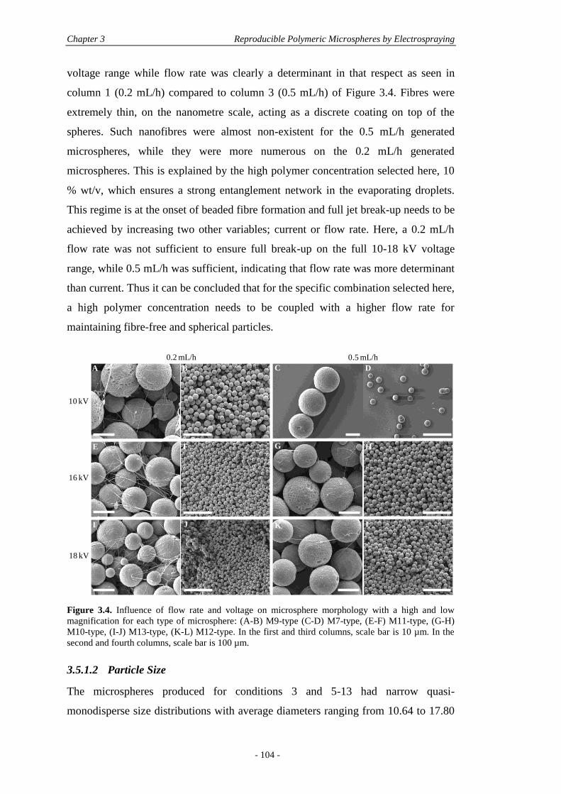
Chapter 3 Reproducible Polymeric Microspheres by Electrospraying
- 104 -
voltage range while flow rate was clearly a determinant in that respect as seen in
column 1 (0.2 mL/h) compared to column 3 (0.5 mL/h) of Figure 3.4. Fibres were
extremely thin, on the nanometre scale, acting as a discrete coating on top of the
spheres. Such nanofibres were almost non-existent for the 0.5 mL/h generated
microspheres, while they were more numerous on the 0.2 mL/h generated
microspheres. This is explained by the high polymer concentration selected here, 10
% wt/v, which ensures a strong entanglement network in the evaporating droplets.
This regime is at the onset of beaded fibre formation and full jet break-up needs to be
achieved by increasing two other variables; current or flow rate. Here, a 0.2 mL/h
flow rate was not sufficient to ensure full break-up on the full 10-18 kV voltage
range, while 0.5 mL/h was sufficient, indicating that flow rate was more determinant
than current. Thus it can be concluded that for the specific combination selected here,
a high polymer concentration needs to be coupled with a higher flow rate for
maintaining fibre-free and spherical particles.
Figure 3.4. Influence of flow rate and voltage on microsphere morphology with a high and low
magnification for each type of microsphere: (A-B) M9-type (C-D) M7-type, (E-F) M11-type, (G-H)
M10-type, (I-J) M13-type, (K-L) M12-type. In the first and third columns, scale bar is 10 µm. In the
second and fourth columns, scale bar is 100 µm.
3.5.1.2 Particle Size
The microspheres produced for conditions 3 and 5-13 had narrow quasi-
monodisperse size distributions with average diameters ranging from 10.64 to 17.80
0.2 mL/h 0.5 mL/h
10 kV
16 kV
18 kV
A B C D
E F G H
I J K L
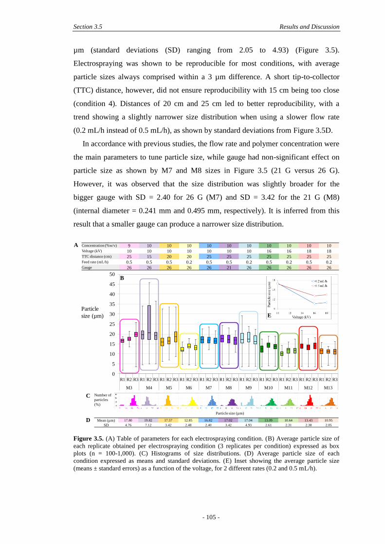
Section 3.5 Results and Discussion
- 105 -
µm (standard deviations (SD) ranging from 2.05 to 4.93) (Figure 3.5).
Electrospraying was shown to be reproducible for most conditions, with average
particle sizes always comprised within a 3 µm difference. A short tip-to-collector
(TTC) distance, however, did not ensure reproducibility with 15 cm being too close
(condition 4). Distances of 20 cm and 25 cm led to better reproducibility, with a
trend showing a slightly narrower size distribution when using a slower flow rate
(0.2 mL/h instead of 0.5 mL/h), as shown by standard deviations from Figure 3.5D.
In accordance with previous studies, the flow rate and polymer concentration were
the main parameters to tune particle size, while gauge had non-significant effect on
particle size as shown by M7 and M8 sizes in Figure 3.5 (21 G versus 26 G).
However, it was observed that the size distribution was slightly broader for the
bigger gauge with SD = 2.40 for 26 G (M7) and SD = 3.42 for the 21 G (M8)
(internal diameter = 0.241 mm and 0.495 mm, respectively). It is inferred from this
result that a smaller gauge can produce a narrower size distribution.
Figure 3.5. (A) Table of parameters for each electrospraying condition. (B) Average particle size of
each replicate obtained per electrospraying condition (3 replicates per condition) expressed as box
plots (n = 100-1,000). (C) Histograms of size distributions. (D) Average particle size of each
condition expressed as means and standard deviations. (E) Inset showing the average particle size
(means ± standard errors) as a function of the voltage, for 2 different rates (0.2 and 0.5 mL/h).
0
5
10
15
20
25
30
35
40
45
50
R1 R2 R3 R1 R2 R3 R1 R2 R3 R1 R2 R3 R1 R2 R3 R1 R2 R3 R1 R2 R3 R1 R2 R3 R1 R2 R3 R1 R2 R3 R1 R2 R3
M3 M4 M5 M6 M7 M8 M9 M10 M11 M12 M13
Concentration (%w/v) 9 10 10 10 10 10 10 10 10 10 10Voltage (kV) 10 10 10 10 10 10 10 16 16 18 18TTC distance (cm) 25 15 20 20 25 25 25 25 25 25 25Feed rate (mL/h) 0.5 0.5 0.5 0.2 0.5 0.5 0.2 0.5 0.2 0.5 0.2Gauge 26 26 26 26 26 21 26 26 26 26 26
Number of
particles
(%)
Particle size (µm)
Particle
size (µm)
A
B
C
E
Mean (µm) 17.80 19.82 17.57 12.85 16.82 17.02 17.04 13.09 10.64 13.43 10.95
SD 4.76 7.12 3.42 2.48 2.40 3.42 4.93 2.61 2.31 2.38 2.05
D
Chapter 3 Reproducible Polymeric Microspheres by Electrospraying
- 106 -
The polymer concentration impacts the surface tension of the solution, affecting
particle size, as reported by Hartman et al. in the cone-jet mode of electrospraying
[42] and shown in Equation 3.3 and 3.4:
(
)
(3.3)
( )
(3.4)
where d is the droplet diameter (m), α is a constant, Q is the liquid flow rate (m3/s), ρ
is the solution density, I is the current, ε0 is the permittivity of vacuum, γ is the
surface tension of solution in ambient air, and K is the liquid conductivity. These
equations indicate that particle size increases with decreasing surface tension and
increases for increasing flow rate, which is in accordance with the results presented
in Figure 3.5D. Yet, for the 9-10% wt/v range studied here, very little differences in
size were observed: for similar electrospraying conditions (M3 and M7), PCL
microspheres made from a 9% wt/v solution led to an average diameter of 17.8 µm
(SD = 4.76) versus 16.8 µm (SD = 2.40) for the 10% wt/v solution. For any drug
release application, such a small size difference would likely not lead to dramatic
differences in release profiles.
Interestingly, although voltage is known to have very little effect on particle size
in PLA-based polymers [100], a significant effect on size was observed from 10 kV
to voltages ≥ 16 kV for PCL microspheres. At 16 and 18 kV, no significant
differences in particle size were observed for each flow rate, as shown by the inset in
Figure 3.5, and as expected from the theory, particle size was only decreased at low
flow rates (0.2 mL/h versus 0.5 mL/h). However, at 10 kV, particle size was
significantly larger than at higher voltages, regardless of flow rates. It might be
inferred that voltage has an influence on particle size, as shown by Equation 3.3
where particle size decreases with increasing current. The reason for this decrease is
the presence of fibres as confirmed by the morphology images (Figure 3.4). In fact,
in Figure 3.4A-D, there is no significant increase in fibre formation for a decreased
flow rate at a fixed voltage of 10 kV, and so there is no significant difference in
particle size for that condition. However at 16 and 18 kV the number of fibres is
increased when decreasing the flow rate and the particle size is decreased
accordingly. Therefore it can be concluded that this decrease in particle size is not
Section 3.5 Results and Discussion
- 107 -
only due to the increased voltage, but it is due to fibre formation occurring for a
combination of lower flow rates and higher voltages. As a consequence, the size of
particles was reduced since a fraction of smaller offspring droplets were ejected from
the initial droplet, drawing extruded fibres along. Using higher voltages are therefore
to be used with care, and a sufficient high flow rate should be chosen to compensate
the need of a high voltage.
From the size distribution plots shown in Figure 3.5C, a bimodal character could
be observed for some conditions, made up of a majority of primary droplets and a
small percentage of smaller particles (less than 5%). These smaller droplets are
offspring droplets caused by Coulomb fission [42, 100]. They are easily ejected from
the primary droplet during shrinkage of droplets occurring during evaporation. The
offspring phenomenon was emphasised for decreased polymer concentration
contents as shown by M3-type microspheres compared to M7-type microspheres (9
and 10% wt/v, respectively). This is likely due to decreased entanglement for
decreased polymer contents, which favours the occurrence of offspring droplets.
However, in this context, the frequency of offspring droplets is extremely low for
most electrospraying conditions and thus would have no significant effect on release
profiles in the case of drug loading.
3.5.1.3 Reproducibility of Electrospraying
To assess reproducibility of particle formation, condition 7 was used, 6 weeks apart.
During this six week break the electrospraying setup was used by other researchers
such that all the parameters had to be reset. The average particle size for the three
runs at week zero was 16.82 µm (n = 330, SD = 2.40) (Figure 3.5) while the repeat at
6 weeks had average particle size of 16.16 µm (n = 289, SD = 3.98) with unchanged
morphology. Apart from non-significant increase in size distribution, the two
conditions were identified as identical.
The same reproducibility was not, however, observed for all conditions. For
instance, conditions, where flat particles were observed (conditions 1 and 2),
intrinsically lacked reproducibility based on same-day repeats. These conditions
reflected the semidilute unentangled regime where smaller offspring droplets were
ejected and droplets were not fully dried.
For semidilute entangled regimes, shown for concentrations > 9% wt/v, more
parameters will influence the reproducibility of electrospraying. For instance, a high
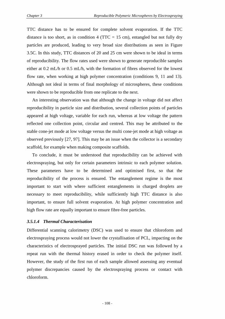
Chapter 3 Reproducible Polymeric Microspheres by Electrospraying
- 108 -
TTC distance has to be ensured for complete solvent evaporation. If the TTC
distance is too short, as in condition 4 (TTC = 15 cm), entangled but not fully dry
particles are produced, leading to very broad size distributions as seen in Figure
3.5C. In this study, TTC distances of 20 and 25 cm were shown to be ideal in terms
of reproducibility. The flow rates used were shown to generate reproducible samples
either at 0.2 mL/h or 0.5 mL/h, with the formation of fibres observed for the lowest
flow rate, when working at high polymer concentration (conditions 9, 11 and 13).
Although not ideal in terms of final morphology of microspheres, these conditions
were shown to be reproducible from one replicate to the next.
An interesting observation was that although the change in voltage did not affect
reproducibility in particle size and distribution, several collection points of particles
appeared at high voltage, variable for each run, whereas at low voltage the pattern
reflected one collection point, circular and centred. This may be attributed to the
stable cone-jet mode at low voltage versus the multi cone-jet mode at high voltage as
observed previously [27, 97]. This may be an issue when the collector is a secondary
scaffold, for example when making composite scaffolds.
To conclude, it must be understood that reproducibility can be achieved with
electrospraying, but only for certain parameters intrinsic to each polymer solution.
These parameters have to be determined and optimised first, so that the
reproducibility of the process is ensured. The entanglement regime is the most
important to start with where sufficient entanglements in charged droplets are
necessary to meet reproducibility, while sufficiently high TTC distance is also
important, to ensure full solvent evaporation. At high polymer concentration and
high flow rate are equally important to ensure fibre-free particles.
3.5.1.4 Thermal Characterisation
Differential scanning calorimetry (DSC) was used to ensure that chloroform and
electrospraying process would not lower the crystallisation of PCL, impacting on the
characteristics of electrosprayed particles. The initial DSC run was followed by a
repeat run with the thermal history erased in order to check the polymer itself.
However, the study of the first run of each sample allowed assessing any eventual
polymer discrepancies caused by the electrospraying process or contact with
chloroform.
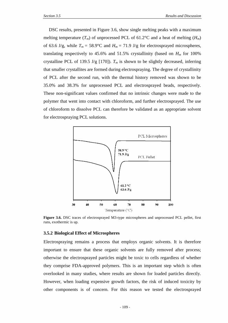
Section 3.5 Results and Discussion
- 109 -
DSC results, presented in Figure 3.6, show single melting peaks with a maximum
melting temperature (Tm) of unprocessed PCL of 61.2°C and a heat of melting (Hm)
of 63.6 J/g, while Tm = 58.9°C and Hm = 71.9 J/g for electrosprayed microspheres,
translating respectively to 45.6% and 51.5% crystallinity (based on Hm for 100%
crystalline PCL of 139.5 J/g [170]). Tm is shown to be slightly decreased, inferring
that smaller crystallites are formed during electrospraying. The degree of crystallinity
of PCL after the second run, with the thermal history removed was shown to be
35.0% and 38.3% for unprocessed PCL and electrosprayed beads, respectively.
These non-significant values confirmed that no intrinsic changes were made to the
polymer that went into contact with chloroform, and further electrosprayed. The use
of chloroform to dissolve PCL can therefore be validated as an appropriate solvent
for electrospraying PCL solutions.
Figure 3.6. DSC traces of electrosprayed M3-type microspheres and unprocessed PCL pellet, first
runs, exothermic is up.
3.5.2 Biological Effect of Microspheres
Electrospraying remains a process that employs organic solvents. It is therefore
important to ensure that these organic solvents are fully removed after process;
otherwise the electrosprayed particles might be toxic to cells regardless of whether
they comprise FDA-approved polymers. This is an important step which is often
overlooked in many studies, where results are shown for loaded particles directly.
However, when loading expensive growth factors, the risk of induced toxicity by
other components is of concern. For this reason we tested the electrosprayed
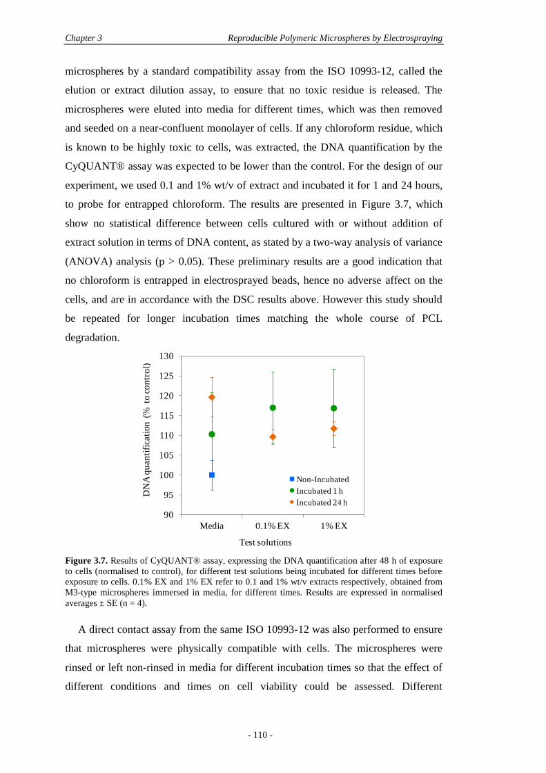
Chapter 3 Reproducible Polymeric Microspheres by Electrospraying
- 110 -
microspheres by a standard compatibility assay from the ISO 10993-12, called the
elution or extract dilution assay, to ensure that no toxic residue is released. The
microspheres were eluted into media for different times, which was then removed
and seeded on a near-confluent monolayer of cells. If any chloroform residue, which
is known to be highly toxic to cells, was extracted, the DNA quantification by the
CyQUANT® assay was expected to be lower than the control. For the design of our
experiment, we used 0.1 and 1% wt/v of extract and incubated it for 1 and 24 hours,
to probe for entrapped chloroform. The results are presented in Figure 3.7, which
show no statistical difference between cells cultured with or without addition of
extract solution in terms of DNA content, as stated by a two-way analysis of variance
(ANOVA) analysis (p > 0.05). These preliminary results are a good indication that
no chloroform is entrapped in electrosprayed beads, hence no adverse affect on the
cells, and are in accordance with the DSC results above. However this study should
be repeated for longer incubation times matching the whole course of PCL
degradation.
Figure 3.7. Results of CyQUANT® assay, expressing the DNA quantification after 48 h of exposure
to cells (normalised to control), for different test solutions being incubated for different times before
exposure to cells. 0.1% EX and 1% EX refer to 0.1 and 1% wt/v extracts respectively, obtained from
M3-type microspheres immersed in media, for different times. Results are expressed in normalised
averages ± SE (n = 4).
A direct contact assay from the same ISO 10993-12 was also performed to ensure
that microspheres were physically compatible with cells. The microspheres were
rinsed or left non-rinsed in media for different incubation times so that the effect of
different conditions and times on cell viability could be assessed. Different
90
95
100
105
110
115
120
125
130
Media 0.1% EX 1% EX
DN
A q
uan
tifi
cati
on (
% t
o c
on
tro
l)
Test solutions
Non-Incubated
Incubated 1 h
Incubated 24 h
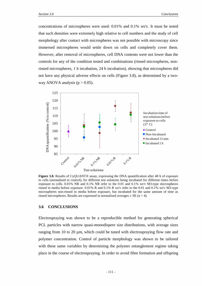
Section 3.6 Conclusions
- 111 -
concentrations of microspheres were used: 0.01% and 0.1% wt/v. It must be noted
that such densities were extremely high relative to cell numbers and the study of cell
morphology after contact with microspheres was not possible with microscopy since
immersed microspheres would settle down on cells and completely cover them.
However, after removal of microspheres, cell DNA contents were not lower than the
controls for any of the condition tested and combinations (rinsed microspheres, non-
rinsed microspheres, 1 h incubation, 24 h incubation), showing that microspheres did
not have any physical adverse effects on cells (Figure 3.8), as determined by a two-
way ANOVA analysis (p > 0.05).
Figure 3.8. Results of CyQUANT® assay, expressing the DNA quantification after 48 h of exposure
to cells (normalised to control), for different test solutions being incubated for different times before
exposure to cells. 0.01% NR and 0.1% NR refer to the 0.01 and 0.1% wt/v M3-type microspheres
rinsed in media before exposure. 0.01% R and 0.1% R wt/v refer to the 0.01 and 0.1% wt/v M3-type
microspheres non-rinsed in media before exposure, but incubated for the same amount of time as
rinsed microspheres. Results are expressed in normalised averages ± SE (n = 4).
3.6 CONCLUSIONS
Electrospraying was shown to be a reproducible method for generating spherical
PCL particles with narrow quasi-monodispere size distributions, with average sizes
ranging from 10 to 20 µm, which could be tuned with electrospraying flow rate and
polymer concentration. Control of particle morphology was shown to be tailored
with these same variables by determining the polymer entanglement regime taking
place in the course of electrospraying. In order to avoid fibre formation and offspring
85
90
95
100
105
110
115
120
125
DN
A q
uan
tifi
cati
on
(%
to
co
ntr
ol)
Test solutions
Control
Non-Incubated
Incubated 15 min
Incubated 1 h
Incubation time of
test solutions before
exposure to cells
(37 C)

Chapter 3 Reproducible Polymeric Microspheres by Electrospraying
- 112 -
droplets, an increased polymer concentration must be coupled with an increased flow
rate, ensuring electrospraying in the semidilute entangled regime, which leads to the
formation of spherical, homogeneous and reproducible particles. Chloroform was
shown to be an appropriate solvent for PCL particles, conferring a reproducible
embossed texture to the electrosprayed microspheres, potentially beneficial for cell
adherence. Chloroform did not act as a plasticiser in contact with PCL and was
inferred to be fully removed after drying. Furthermore, electrosprayed microspheres
showed no adverse effects on cell viability after 48 h exposure. In conclusion, this
study has demonstrated precise control over polymer microsphere characteristics
which may be used as a template for future microsphere-growth factor delivery
systems.
3.7 ACKNOWLEDGEMENTS
T. R. D. acknowledges the Queensland Smart State Fellowship Scheme and Tissue
Therapies Ltd for financial support. M. A. W. is supported by the QUT Vice
Chancellor’s Fellowship Scheme and an ARC Linkage Grant (LP100200084).
Thanks to the ARC (Discovery grant no. DP0989000) for financial support.
3.8 REFERENCES AND NOTES
© 2010 by the authors; licensee MDPI, Basel, Switzerland. This article is an open-
access article distributed under the terms and conditions of the Creative Commons
Attribution license (http://creativecommons.org/licenses/by/3.0/).
- 113 -
Chapter 4: Controlling Microencapsulation and
Release of Micronised Proteins using
Poly(Ethylene Glycol) and
Electrospraying
Nathalie Bock1,2,3
, Tim R. Dargaville1, Maria A. Woodruff
2
Published in the European Journal of Pharmaceutics and Biopharmaceutics,
Volume 87, Issue 2, 2014, Pages 366-377.
© 2014 Elsevier B.V. All rights reserved.
Statement of contribution of co-authors for thesis by published papers
Contributors Statement of contribution
Nathalie Bock Developed the research questions
Designed and performed the experiments
Analysed and interpreted the results
Conceived and wrote the manuscript
Tim R. Dargaville* Involved in the conception of the project
Assisted in reviewing the manuscript
Maria A. Woodruff* Involved in the conception of the project
Assisted in reviewing the manuscript
1 Tissue Repair and Regeneration Group
2 Biomaterials and Tissue Morphology Group
3 Regenerative Medicine Group
Institute of Health and Biomedical Innovation, Queensland University of Technology,
60 Musk Avenue, Kelvin Grove, QLD 4059, Australia

Chapter 4 Microencapsulation of Proteins with PEG and Electrospraying
- 114 -
The authors listed above have certified* that:
1. they meet the criteria for authorship in that they have participated in the
conception, execution, or interpretation, of at least that part of the publication in
their field of expertise;
2. they take public responsibility for their part of the publication, except for the
responsible author who accepts overall responsibility for the publication;
3. there are no other authors of the publication according to these criteria;
4. potential conflicts of interest have been disclosed to (a) granting bodies, (b) the
editor or publisher of journals or other publications, and (c) the head of the
responsible academic unit, and
5. they agree to the use of the publication in the student’s thesis and its publication
on the QUT ePrints database consistent with any limitations set by publisher
requirements.
Principal Supervisor Confirmation
I have sighted email or other correspondence from all Co-authors confirming their
certifying authorship.
Section 4.1 Abstract
- 115 -
4.1 ABSTRACT
The fabrication of tailored microparticles for delivery of therapeutics is a challenge
relying upon a complex interplay between processing parameters and materials
properties. The emerging use of electrospraying allows better tailoring of particle
morphologies and sizes than current techniques, critical to reproducible release
profiles. While dry encapsulation of proteins is essential for the release of active
therapeutics from microparticles, it is currently uncharacterised in electrospraying.
To this end, poly(ethylene glycol) (PEG) was assessed as a micronising and
solubilising agent for dry protein encapsulation and release from electrosprayed
particles made from polycaprolactone (PCL). The physical effect of PEG in protein-
loaded poly(lactic-co-glycolic acid) (PLGA) particles was also studied, for
comparison. The addition of 5-15% wt PEG 6 kDa or 35 kDa resulted in reduced
particle sizes and broadened distributions, which could be improved by tailoring the
electrospraying processing parameters, namely by reducing polymer concentration
and increasing flow rate. Upon micronisation, protein particle size was reduced to the
micrometer domain, resulting in homogenous encapsulation in electrosprayed PCL
microparticles. Microparticle size distributions were shown to be the most
determinant factor for protein release by diffusion, and allowed specific control of
release patterns.
4.2 KEYWORDS
Electrospraying, drug delivery, encapsulation, in vitro release, microparticles,
micronisation, polycaprolactone, poly(ethylene glycol), protein.
4.3 INTRODUCTION
Conventional intravenous delivery of therapeutics suffers from excessive dosage
being administered and poor bio-availability [11]. In response, the encapsulation of
drugs and proteins in carriers has drawn the attention of pharmaceutical research for
many decades, yet the systems developed are far from optimal. A resorbable carrier,
such as a polymer matrix, has the potential to efficiently protect therapeutic
molecules after administration, while providing sustained delivery upon matrix
degradation [125]. However, the processes of encapsulation involve organic solvents,
Chapter 4 Microencapsulation of Proteins with PEG and Electrospraying
- 116 -
shear forces and hydrophobic polymers which may partly denature hydrophilic
protein molecules and affect release kinetics [171]. Dry encapsulation of proteins is a
strategy to minimise protein denaturation by avoiding water-in-oil interfaces used in
traditional techniques, well-acknowledged to denature proteins [35]. While the dry
protein is in contact with organic solvent during processing, the solvent provides
limited molecular mobility for the protein due to the anhydrous environment.
Although the native state of a protein is not favoured thermodynamically in such
solvents, this combination provides a kinetic trap for the protein, which maintains
protein activity [34].
Size reduction of protein aggregates, or micronisation, is critical to ensure high,
homogeneous, and dispersed protein encapsulation in polymeric carriers upon
solvent removal, and represents an intricate challenge in the current protein delivery
systems. Techniques such as spray-drying and ultrasonic atomization have been used
to obtain fine protein particles, but low yields make the techniques unpractical while
harsh stresses (mechanical, heat) may lead to protein denaturation issues [171]. An
easier process was developed by Morita et al., involving co-lyophilisation of the
protein with poly(ethylene glycol) (PEG) [172]. Lyophilisation in the pharmaceutical
field has been subjected to ongoing development and is well-known as an approach
to overcome the physical and chemical instabilities of protein molecules [173]. When
co-lyophilising PEG and a protein solution, PEG effectively raises the energy barrier
for protein molecules to extend their hydrophobic domains to each other, resulting in
reduced aggregation with a progressive shrinkage of protein particles [171, 174].
Extensive protein conformational changes are also prevented by PEG coating at the
surface of proteins, improving both protein stability and delivery capacity [175, 176].
Various proteins have been successfully micronised into spherical microparticles
with diameters less than 5 µm, including serum albumin (SA), superoxide dismutase
(SOD), horseradish peroxidase (HRP) and gelatin, according to different
PEG:protein ratios [127, 172, 177]. Protein aggregate size was found to decrease
linearly with the increase in PEG:protein weight ratio and a critical value was found,
upon which the size decrease was slower. Importantly, the micronisation process did
not alter the protein and full activity was recovered in the case of SOD [127].
Efficient size reduction, less than 1 µm in diameter, improved the encapsulation
efficiency (EE) of active HRP from 24% to 87% [127], and reduced burst release of
SA [178] using solid/emulsion-based microencapsulation techniques. It was also
Section 4.3 Introduction
- 117 -
shown that proteins and PEG could form stable nano-sized complexes in polar
organic solvents by non-covalent interactions, allowing for homogeneous and high
EE when dispersed in a PLGA solution and spray-dried [179].
Bioactivity and release profiles can also be efficiently tailored by the use of PEG
in formulations since the presence of a hydrophilic additive in a hydrophobic
polymer matrix increases diffusion of the encapsulated protein by increasing the
degree of pores in the matrix whilst increasing transport of acidic degradation
products away from the matrix [40, 171, 180]. In a study by Jiang et al., different
concentrations of PEG were indeed shown to affect the release of SA from
polylactide (PLA) microspheres, with increased release rates for 20% of PEG present
in the PLA matrix, compared to 0-10%, but similar profiles were obtained when
comparing the inclusions of PEG 10 kDa and 20 kDa [180]. Protein particle size is
also critical in directing release profiles with larger protein particles leading to burst
release profiles, due to a reduced diffusion of larger protein particles inside a
polymer droplet, resulting in an increased protein concentration near the surface of
polymeric particles [52]. For micronised proteins, a homogeneous and fine
distribution within the particle allows thorough water intrusion, leading to a dense
pore network upon release. Such a feature is essential in enabling sustained,
reproducible and complete release, although it is currently under-assessed [119].
While several techniques allow solid encapsulation, the emerging technique of
electrospraying, in particular, may be highly suited for the efficient encapsulation of
therapeutics in polymeric particles [181]. In electrospraying, the protein may directly
be dispersed in the polymer solution, which, following subjection to high voltage,
results in the extrusion of loaded droplets from a syringe. Droplets undergo solvent
evaporation and can be collected, dry, from a conductive substrate. This simple
process does not require heat or a sophisticated setup, but involves a complex
interplay between processing parameters and polymer solution properties.
Nevertheless, our previous reports have shown that a tight control of particle size and
morphology can be obtained [83, 182], which in combination with dry encapsulation
may be suitable in ensuring reproducible release profiles and active proteins being
released. However, no reports to date, have mentioned or addressed protein
micronisation prior to electrospraying, which is critical for homogeneous
encapsulation of proteins in polymeric particles [181]. Hence, it is hypothesised in
this study that PEG may be used as a micronising agent and a means of tailoring
Chapter 4 Microencapsulation of Proteins with PEG and Electrospraying
- 118 -
release from electrosprayed particles. A model protein, SA, will be micronised by co-
lyophilisation with PEG prior to electrospraying and the effect of PEG in the final
particle formulation comprising polycaprolactone (PCL) and PLGA 85:15, both
FDA-approved polyesters suitable for sustained delivery systems, will be assessed in
terms of miscibility of polymers, particle microstructure, protein encapsulation
efficiency and protein release.
4.4 EXPERIMENTAL SECTION
4.4.1 Materials
Polycaprolactone (Mn = 84 kDa, PDI 1.53) was obtained from Perstorp Ltd, UK.
Poly(lactic-co-glycolic acid) with a lactide:glycolide (L:G) ratio of 85:15 (Mn = 41.3
kDa, PDI 1.6) was purchased from Evonik Industries, USA. Poly(ethylene glycol)
with Mn = 6 kDa and Mn = 35 kDa, referred hereafter as PEG 6k and PEG 35k,
respectively, dichloromethane (DCM), sodium dodecyl sulphate (SDS), serum
albumin (SA) and fluorescein isothiocyanate (FITC)-conjugated SA were purchased
from Sigma-Aldrich, Australia. Chloroform was purchased from Merck, Germany.
4.4.2 Particle Fabrication
4.4.2.1 Solid Dispersion of Dry Protein
First, the protein was micronised [172]. Briefly, a series of solutions containing the
protein (SA or FITC-SA) mixed with PEG (6k or 35k) were freeze-dried. Various
polymer solutions made of PCL or PLGA 85:15 were prepared in chloroform or
DCM and subsequently added to the protein:PEG lyophilisate under magnetic
stirring (see Table 4.1 for details of constituents and ratios). The resultant dispersions
were vortexed for 10 s (after addition of 1 mL of polymer solution and ultimately
probe sonicated for 1 min at 0.5 W (continuous regime, Misonix 3,000, USA) to
ensure protein dispersion in the organic solvent.
4.4.2.2 Electrospraying
Electrospraying was used to produce dried microparticles encapsulating the proteins.
Ambient temperature and relative humidity ranged from 23 to 24°C, and 34 to 49%,
respectively. The polymer dispersions were loaded in a 1 mL glass syringe
(Hamilton, USA) and extruded through stainless steel nozzles ranging from 26 to 21
G (Terumo, Japan and Becton Dickinson, USA) at constant rates ranging from 0.5
Section 4.4 Experimental Section
- 119 -
mL/h to 3 mL/h (see Table 4.1 for details of parameters) using a syringe pump
(World Precision Instruments, USA). A voltage of 10 kV was applied to the needle
tip. The tip-to-collector (TTC) distance was either 15 or 25 cm. Collectors consisted
of standard aluminium foils (20 × 20 cm2) (General purpose, Bulls Eye Food
Services) washed with 70% ethanol. After electrospraying, the collectors were placed
under vacuum for a further 72 hours, to remove any solvent residue. The dry
microparticles were then transferred into glass vials and stored at -18°C until further
analysis.
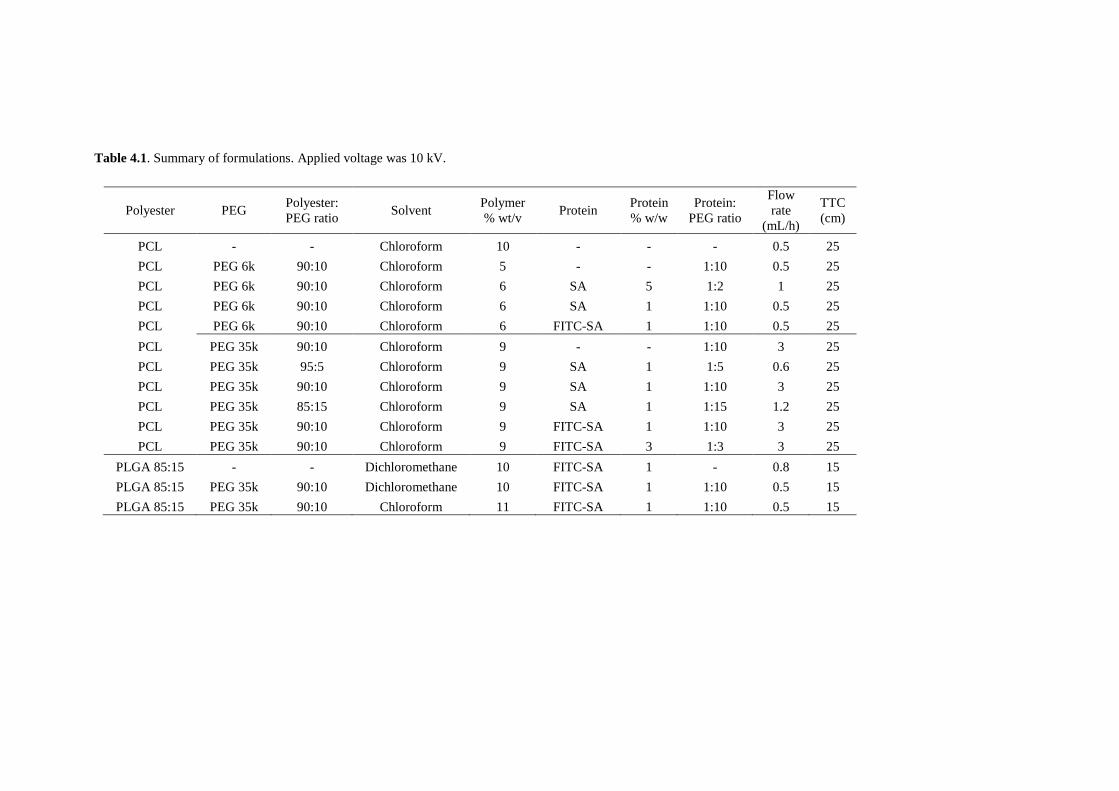
Table 4.1. Summary of formulations. Applied voltage was 10 kV.
Polyester PEG Polyester:
PEG ratio Solvent
Polymer
% wt/v Protein
Protein
% w/w
Protein:
PEG ratio
Flow
rate
(mL/h)
TTC
(cm)
PCL - - Chloroform 10 - - - 0.5 25
PCL PEG 6k 90:10 Chloroform 5 - - 1:10 0.5 25
PCL PEG 6k 90:10 Chloroform 6 SA 5 1:2 1 25
PCL PEG 6k 90:10 Chloroform 6 SA 1 1:10 0.5 25
PCL PEG 6k 90:10 Chloroform 6 FITC-SA 1 1:10 0.5 25
PCL PEG 35k 90:10 Chloroform 9 - - 1:10 3 25
PCL PEG 35k 95:5 Chloroform 9 SA 1 1:5 0.6 25
PCL PEG 35k 90:10 Chloroform 9 SA 1 1:10 3 25
PCL PEG 35k 85:15 Chloroform 9 SA 1 1:15 1.2 25
PCL PEG 35k 90:10 Chloroform 9 FITC-SA 1 1:10 3 25
PCL PEG 35k 90:10 Chloroform 9 FITC-SA 3 1:3 3 25
PLGA 85:15 - - Dichloromethane 10 FITC-SA 1 - 0.8 15
PLGA 85:15 PEG 35k 90:10 Dichloromethane 10 FITC-SA 1 1:10 0.5 15
PLGA 85:15 PEG 35k 90:10 Chloroform 11 FITC-SA 1 1:10 0.5 15
Section 4.4 Experimental Section
- 121 -
4.4.3 Physical Characterisation
4.4.3.1 Proteins
The dispersion of proteins within electrosprayed particles was assessed using
albumin labelled with a florescent dye (FITC). The distribution of FITC-SA within
microparticles was visualised using confocal laser scanning microscopy (CLSM). To
randomly collect FITC-SA-loaded particles, a microscope glass slide was introduced
in the electrospraying apparatus housing and held in contact with the collector, in the
centre of the spraying zone for 5 minutes, while electrospraying. The slide was then
removed and fluorescence images were captured using a Leica TCS SP5 confocal
laser scanning microscope (Leica Microsystems, Wetzlar, Germany), 63× objective
with a 9.7× zoom. Excitation was 488 nm and emission was captured between 495
nm and 633 nm.
4.4.3.2 Electrosprayed Microparticles
Particle morphology was characterised with a FEI Quanta 200 scanning electron
microscope (SEM) operating at 10 kV in high vacuum mode. Microparticles were
gently taped on aluminium stubs and gold coated for 225 s at 30 mA (SC500 sputter
coater, Bio-Rad, Australia). Particle size was assessed with ImageJ analysis software
(National Health Institutes (NIH)) based on light micrographs (AxoVision, Carl
Zeiss MicroImaging GmbH, Germany). Results were plotted as box plots and
expressed in medians with n = 330-570 particles per formulation.
4.4.4 In Vitro Characterisation
4.4.4.1 Encapsulation Efficiency
Protein content in the microparticles was determined using two extraction
procedures. For the first extraction (referred as EX1), particles (8 mg) were dissolved
in DCM (2 mL), n = 3. Phosphate buffer saline (PBS) (3 mL) was then added to the
dispersions and tubes were vortexed for 2 min to extract SA (Vortex Mixer SA3,
Stuart Scientific). The resultant emulsions were centrifuged at 5,000 rpm for 15 min
to separate the aqueous phase containing SA from the organic phase containing
dissolved polymer. The aqueous phase was collected and another extraction cycle
was performed to maximize SA recovery. The collected aqueous phase was analysed
by the micro-bicinchoninic acid (µBCA) assay (Thermo Fisher Scientific, Australia)
using a standard curve prepared by serial dilutions of the supplied SA from 40 to 0
Chapter 4 Encapsulation of Proteins in Electrosprayed Microparticles
- 122 -
µg/mL. A polynomial fit was deducted from the corresponding absorbance readings
at 562 nm (R2 = 0.9991) (Microplate Manager V5.2, Benchmark Plus
spectrophotometer, Bio-Rad, USA). When determining the EE of FITC-SA loaded
microparticles, a separate calibration curve was similarly prepared with FITC-SA to
ensure no interferences with the µBCA assay (absorbance read at λ = 562 nm). The
calibration curve was the same as normal SA, within the linear range up to 20
µg/mL, above which slightly reduced absorbance values were detected.
Encapsulation efficiency (EE) (%) was measured according to EE = Measured SA
content (µg) / Theoretical SA content (µg) × 100. The second extraction procedure
(referred as EX2) was similar than the first one, except that particles (10 mg) were
extracted with PBS (4 mL) supplemented with 5 mM of SDS, n = 5. Only one
extraction cycle was performed with no centrifugation. Protein was quantified using
the µBCA assay.
4.4.4.2 In Vitro Release
Particles (10 mg) were placed in 2 mL screw-capped microtubes (Sarstedt, Germany)
and filled with PBS (1.5 mL) containing 0.02% wt/v sodium azide. Tubes were
agitated at a speed of 8 rpm at 37°C for 81 days. At specific time points, tubes were
centrifuged at 28,000g for 2 min to settle particles before 1 mL of supernatant was
collected and replaced by the same amount of fresh PBS. The supernatant of both
RS1 and RS2 was analysed by the µBCA assay using the same technique described
in the encapsulation efficiency section.
4.5 RESULTS AND DISCUSSION
4.5.1 Physical Characterisation
4.5.1.1 Miscibility Considerations with Hansen Solubility Parameter
Any given mixture is governed by a combination of thermodynamics, kinetics and
evaporation processes. Miscibility, in particular, is very important in electrospraying
since immiscible substances may lead to electrospraying jet instabilities, resulting in
poor chain entanglements and non-spherical/irreproducible morphologies. Hence, in
this section, thermodynamics insights will be considered in regards to the miscibility
of PLGA and PCL with PEG, and with possible solvents used in electrospraying, in
order to determine a suitable combination for optimal protein encapsulation in
electrosprayed particles.
Section 4.5 Results and Discussion
- 123 -
4.5.1.1.1 Definitions
In drug-polymer systems, local interdiffusion is possible and can be expressed by
Flory-Huggins theory [183, 184], and the Hansen solubility parameter (HSP) of a
substance [185, 186]. HSP can be divided into δD, δP and δH, representative of the
non-polar or dispersion (D) forces (such as van der Waals interactions), the polar (P)
forces and the hydrogen (H) bonding nature of species [185] (Equation 4.1):
(4.1)
The closer the parameters of two substances are, the better the miscibility of one
substance in the other [187], and hence solubility parameters are useful in
determining the miscibility of drugs in polymers in drug-polymer binary systems.
For instance Mastumoto et al. used a variant of HSP to predict the presence of
cisplatin and other drugs in the PLGA or PLA phase of blended PLGA:PLA
microspheres with various solvents [188].
The limitation of the solubility parameter and Flory-Huggins theory is that they
cannot be applied to complex structures such as proteins. While proteins can be
characterised by their chain conformation like polymers, they adopt specific native
conformations under different conditions, hence resulting in different atomic and
molecular forces [189]. When mixed in an organic solvent, hydrogen bonding forces
would be significantly affected, and results in even more complex calculations,
although extended Hansen regression models can be used [190]. Gander et al.
showed that the solubility parameters were indeed insufficient for predicting
microsphere properties of spray-dried PLA encapsulating serum albumin, but that
extending the solubility parameters to electrostatic and covalent considerations was
more powerful [191]. Due to the complexities of protein tertiary structure, we have
thus chosen here to use HSP to determine an ideal polymer-solvent combination that
excludes the protein.
The Hansen partial solubilities of a substance can be identified as 3D coordinates
in the ‘Hansen solubility space’, representing the centre of a solubility sphere which
includes the solvents and excludes the non-solvents. While the radius of the sphere
R0 needs to be determined experimentally, R0 of many polymers have been
characterised and can be found in the literature and software databases [185, 186].
Hence, in order to define the miscibility of a polymer (p) in any solvent (s), the
Chapter 4 Encapsulation of Proteins in Electrosprayed Microparticles
- 124 -
‘distance’, Ra, between two materials can be plotted in the Hansen solubility space,
and is expressed in Equation 4.2 [185]:
( )
( )
( )
(4.2)
Materials with similar solubilities will have a small Ra and hence will be more
miscible. Although Ra can be thought as a physical distance in the Hansen solubility
space, it represents energy and is expressed in (J/cm3)1/2
. By dividing Ra by Ro, the
relative energy difference (RED) number can be defined as in Equation 4.3:
(4.3)
A RED number less than 1 indicates miscibility while a number higher than 1
indicate immiscibility. In general, RED numbers progressively higher indicate lower
affinities.
4.5.1.1.2 Applications of Hansen Solubility Parameter
The Hansen partial solubility parameters can be calculated by the group contribution
(GC) method, however this calculation does not take into account the molecular
weight of a polymer, which has been shown to affect to a certain extent the
parameters [192]. As a result, partial solubility parameters can also be assessed
experimentally, by swelling tests, turbidimetric titrations, viscosity measurements
and inverse gas chromatography [192]. While results from swelling are generally in
good agreement with the GC method, δP values obtained by titration methods can be
low and unrealistic [193].
Here, PLGA and PCL were assessed in association with PEG and the possible
solvents used in electrospraying. Table 4.2 summarises the partial solubility
parameters of these materials found in the literature with the closest molecular
weights and L:G ratio (for PLGA) of the polymers used in this study.
Section 4.5 Results and Discussion
- 125 -
Table 4.2. Solubility parameters of selected polymers and solvents obtained by different methods,
expressed in √ .
δD δP δH R0 Method Ref
PCL 17 4.8 8.3 - GC [194]
PCL 14 kDa 17.8 6.1 7.8 7.1 Swelling [194]
PCL 65 kDa 17.8 6.2 7.7 5.5 Swelling [194]
PLGA 85:15 16 9.3 11.4 - GC [193]
PLGA 85:15 75 kDa 17.4 8.3 9.9 8 Swelling [193]
PEO, PEG 17 10 5 8 HSP
database [186]
PEG 17.8 11.1 9.1 - GC [195]
Chloroform 17.8 3.1 5.7 - GC [185]
Dichloromethane 18.2 6.3 6.1 - GC [185]
Ethanol 15.8 8.8 19.4 - GC [185]
Acetone 15.5 10.4 7 - GC [185]
N,N-dimethylformamide 17.4 13.7 11.3 - GC [185]
When plotting a 2D projection of the solubility sphere of the three polymers of
interest and possible solvents used in electrospraying (Figure 4.1), both chloroform
and dichloromethane (DCM) are within all the spheres of PLGA, PCL and PEG.
None of the polymers are miscible with ethanol, but while PLGA and PEG are
miscible with acetone and N,N-dimethylformamide (DMF), it is not the case of PCL.
RED values are presented in Table 4.3, with RED values larger than 1 indicating
immiscibility. From the solvents studied here, RED was shown to be the smallest for
chloroform and DCM.
The association of PEG to PLGA provided similar compatibility to PLGA alone,
but an increase of Ra was observed with the addition of PEG to PCL compared to
PCL alone (Figure 4.2). In all cases these values are low, indicating that the blending
of PEG to PCL or PLGA with both chloroform and dichloromethane did not
dramatically, or not at all, decrease miscibility, and as such they can be considered
good solvents for those blends and will be used hereafter.
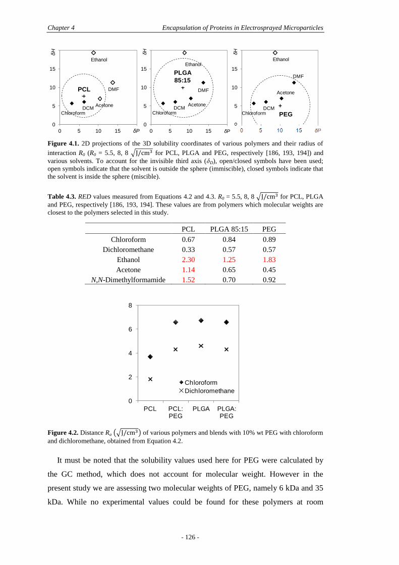
Chapter 4 Encapsulation of Proteins in Electrosprayed Microparticles
- 126 -
Figure 4.1. 2D projections of the 3D solubility coordinates of various polymers and their radius of
interaction R0 (R0 = 5.5, 8, 8 √ for PCL, PLGA and PEG, respectively [186, 193, 194]) and
various solvents. To account for the invisible third axis (δD), open/closed symbols have been used;
open symbols indicate that the solvent is outside the sphere (immiscible), closed symbols indicate that
the solvent is inside the sphere (miscible).
Table 4.3. RED values measured from Equations 4.2 and 4.3. R0 = 5.5, 8, 8 √ for PCL, PLGA
and PEG, respectively [186, 193, 194]. These values are from polymers which molecular weights are
closest to the polymers selected in this study.
PCL PLGA 85:15 PEG
Chloroform 0.67 0.84 0.89
Dichloromethane 0.33 0.57 0.57
Ethanol 2.30 1.25 1.83
Acetone 1.14 0.65 0.45
N,N-Dimethylformamide 1.52 0.70 0.92
Figure 4.2. Distance Ra (√ ) of various polymers and blends with 10% wt PEG with chloroform
and dichloromethane, obtained from Equation 4.2.
It must be noted that the solubility values used here for PEG were calculated by
the GC method, which does not account for molecular weight. However in the
present study we are assessing two molecular weights of PEG, namely 6 kDa and 35
kDa. While no experimental values could be found for these polymers at room
0
5
10
15
20
0 5 10 15 20
δH
δP
ChloroformDCM
Acetone
DMF
Ethanol
0
5
10
15
20
0 5 10 15 20
δH
δP
Acetone
DMF
Ethanol
0
5
10
15
20
0 5 10 15 20
δH
δP
Acetone
DMF
Ethanol
PCL
PLGA
85:15
PEGChloroformDCM
ChloroformDCM
0
2
4
6
8
PCL PCL:PEG
PLGA PLGA:PEG
Chloroform
Dichloromethane
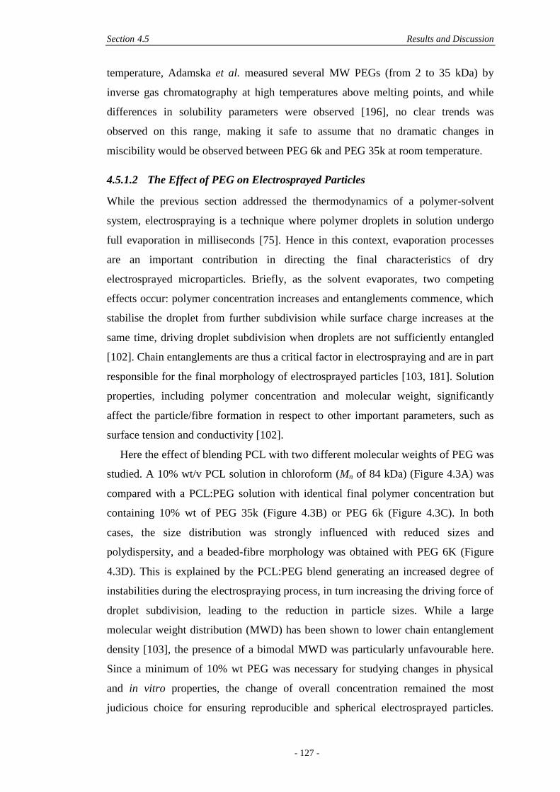
Section 4.5 Results and Discussion
- 127 -
temperature, Adamska et al. measured several MW PEGs (from 2 to 35 kDa) by
inverse gas chromatography at high temperatures above melting points, and while
differences in solubility parameters were observed [196], no clear trends was
observed on this range, making it safe to assume that no dramatic changes in
miscibility would be observed between PEG 6k and PEG 35k at room temperature.
4.5.1.2 The Effect of PEG on Electrosprayed Particles
While the previous section addressed the thermodynamics of a polymer-solvent
system, electrospraying is a technique where polymer droplets in solution undergo
full evaporation in milliseconds [75]. Hence in this context, evaporation processes
are an important contribution in directing the final characteristics of dry
electrosprayed microparticles. Briefly, as the solvent evaporates, two competing
effects occur: polymer concentration increases and entanglements commence, which
stabilise the droplet from further subdivision while surface charge increases at the
same time, driving droplet subdivision when droplets are not sufficiently entangled
[102]. Chain entanglements are thus a critical factor in electrospraying and are in part
responsible for the final morphology of electrosprayed particles [103, 181]. Solution
properties, including polymer concentration and molecular weight, significantly
affect the particle/fibre formation in respect to other important parameters, such as
surface tension and conductivity [102].
Here the effect of blending PCL with two different molecular weights of PEG was
studied. A 10% wt/v PCL solution in chloroform (Mn of 84 kDa) (Figure 4.3A) was
compared with a PCL:PEG solution with identical final polymer concentration but
containing 10% wt of PEG 35k (Figure 4.3B) or PEG 6k (Figure 4.3C). In both
cases, the size distribution was strongly influenced with reduced sizes and
polydispersity, and a beaded-fibre morphology was obtained with PEG 6K (Figure
4.3D). This is explained by the PCL:PEG blend generating an increased degree of
instabilities during the electrospraying process, in turn increasing the driving force of
droplet subdivision, leading to the reduction in particle sizes. While a large
molecular weight distribution (MWD) has been shown to lower chain entanglement
density [103], the presence of a bimodal MWD was particularly unfavourable here.
Since a minimum of 10% wt PEG was necessary for studying changes in physical
and in vitro properties, the change of overall concentration remained the most
judicious choice for ensuring reproducible and spherical electrosprayed particles.
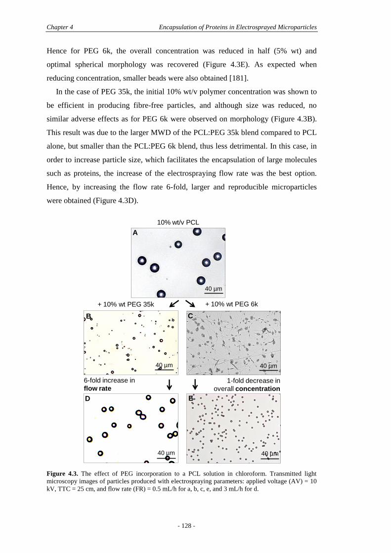
Chapter 4 Encapsulation of Proteins in Electrosprayed Microparticles
- 128 -
Hence for PEG 6k, the overall concentration was reduced in half (5% wt) and
optimal spherical morphology was recovered (Figure 4.3E). As expected when
reducing concentration, smaller beads were also obtained [181].
In the case of PEG 35k, the initial 10% wt/v polymer concentration was shown to
be efficient in producing fibre-free particles, and although size was reduced, no
similar adverse effects as for PEG 6k were observed on morphology (Figure 4.3B).
This result was due to the larger MWD of the PCL:PEG 35k blend compared to PCL
alone, but smaller than the PCL:PEG 6k blend, thus less detrimental. In this case, in
order to increase particle size, which facilitates the encapsulation of large molecules
such as proteins, the increase of the electrospraying flow rate was the best option.
Hence, by increasing the flow rate 6-fold, larger and reproducible microparticles
were obtained (Figure 4.3D).
Figure 4.3. The effect of PEG incorporation to a PCL solution in chloroform. Transmitted light
microscopy images of particles produced with electrospraying parameters: applied voltage (AV) = 10
kV, TTC = 25 cm, and flow rate (FR) = 0.5 mL/h for a, b, c, e, and 3 mL/h for d.
+ 10% wt PEG 35k
1-fold decrease in
overall concentration
6-fold increase in
flow rate
40 µm
A
40 µm
C
40 µm
D
40 µm
E
+ 10% wt PEG 6k
10% wt/v PCL
40 µm
B
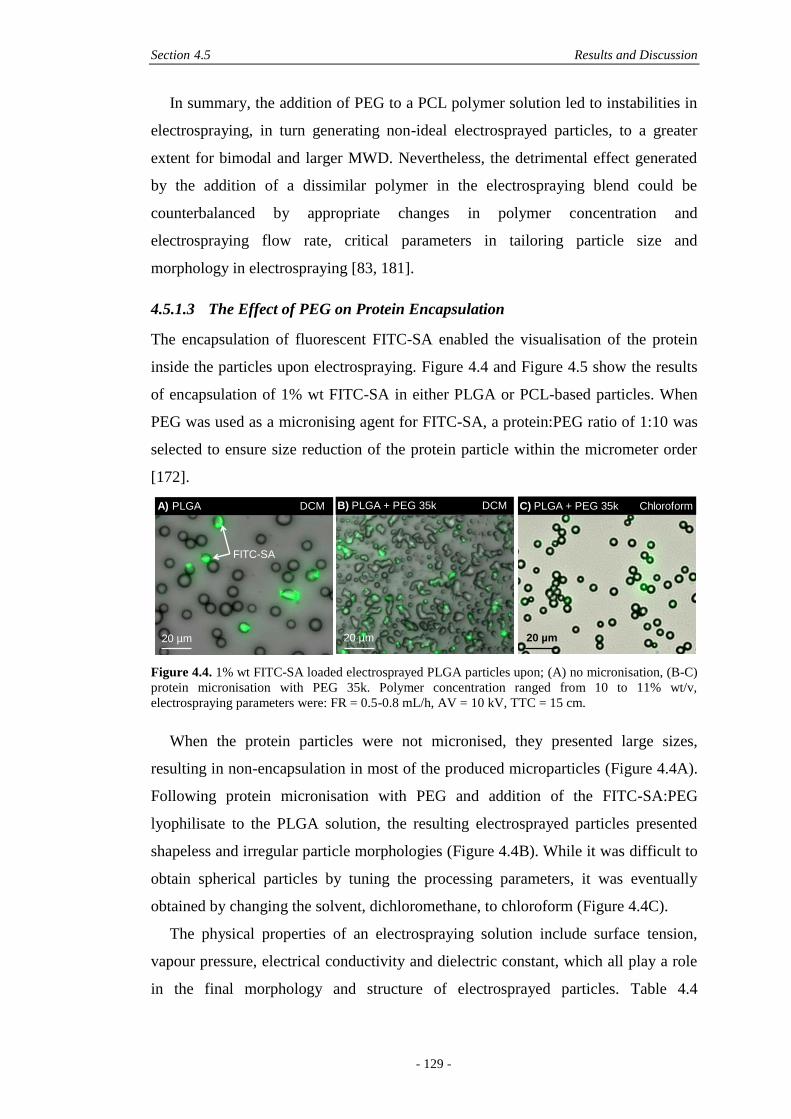
Section 4.5 Results and Discussion
- 129 -
In summary, the addition of PEG to a PCL polymer solution led to instabilities in
electrospraying, in turn generating non-ideal electrosprayed particles, to a greater
extent for bimodal and larger MWD. Nevertheless, the detrimental effect generated
by the addition of a dissimilar polymer in the electrospraying blend could be
counterbalanced by appropriate changes in polymer concentration and
electrospraying flow rate, critical parameters in tailoring particle size and
morphology in electrospraying [83, 181].
4.5.1.3 The Effect of PEG on Protein Encapsulation
The encapsulation of fluorescent FITC-SA enabled the visualisation of the protein
inside the particles upon electrospraying. Figure 4.4 and Figure 4.5 show the results
of encapsulation of 1% wt FITC-SA in either PLGA or PCL-based particles. When
PEG was used as a micronising agent for FITC-SA, a protein:PEG ratio of 1:10 was
selected to ensure size reduction of the protein particle within the micrometer order
[172].
Figure 4.4. 1% wt FITC-SA loaded electrosprayed PLGA particles upon; (A) no micronisation, (B-C)
protein micronisation with PEG 35k. Polymer concentration ranged from 10 to 11% wt/v,
electrospraying parameters were: FR = 0.5-0.8 mL/h, AV = 10 kV, TTC = 15 cm.
When the protein particles were not micronised, they presented large sizes,
resulting in non-encapsulation in most of the produced microparticles (Figure 4.4A).
Following protein micronisation with PEG and addition of the FITC-SA:PEG
lyophilisate to the PLGA solution, the resulting electrosprayed particles presented
shapeless and irregular particle morphologies (Figure 4.4B). While it was difficult to
obtain spherical particles by tuning the processing parameters, it was eventually
obtained by changing the solvent, dichloromethane, to chloroform (Figure 4.4C).
The physical properties of an electrospraying solution include surface tension,
vapour pressure, electrical conductivity and dielectric constant, which all play a role
in the final morphology and structure of electrosprayed particles. Table 4.4
20 µm
A) PLGA DCM B) PLGA + PEG 35k DCM C) PLGA + PEG 35k Chloroform
20 µm 20 µm
FITC-SA
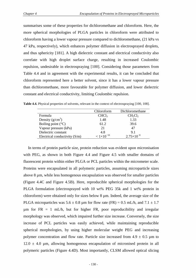
Chapter 4 Encapsulation of Proteins in Electrosprayed Microparticles
- 130 -
summarises some of these properties for dichloromethane and chloroform. Here, the
more spherical morphologies of PLGA particles in chloroform were attributed to
chloroform having a lower vapour pressure compared to dichloromethane, (21 kPa vs
47 kPa, respectively), which enhances polymer diffusion in electrosprayed droplets,
and thus sphericity [181]. A high dielectric constant and electrical conductivity also
correlate with high droplet surface charge, resulting in increased Coulombic
repulsion, undesirable in electrospraying [100]. Considering those parameters from
Table 4.4 and in agreement with the experimental results, it can be concluded that
chloroform represented here a better solvent, since it has a lower vapour pressure
than dichloromethane, more favourable for polymer diffusion, and lower dielectric
constant and electrical conductivity, limiting Coulombic repulsion.
Table 4.4. Physical properties of solvents, relevant in the context of electrospraying [100, 108].
Chloroform Dichloromethane
Formula CHCl3 CH2Cl2
Density (g/cm3) 1.48 1.33
Boiling point (°C) 61.2 39.6
Vapour pressure (kPa) 21 47
Dielectric constant 4.8 9.1
Electrical conductivity (S/m) < 1×10⁻¹⁰
2.75×10⁻⁸
In terms of protein particle size, protein reduction was evident upon micronisation
with PEG, as shown in both Figure 4.4 and Figure 4.5 with smaller domains of
fluorescent protein within either PLGA or PCL particles within the micrometer scale.
Proteins were encapsulated in all polymeric particles, assuming microparticle sizes
above 8 µm, while less homogenous encapsulation was observed for smaller particles
(Figure 4.4C and Figure 4.5B). Here, reproducible spherical morphologies for the
PLGA formulation (electrosprayed with 10 wt% PEG 35k and 1 wt% protein in
chloroform) were obtained only for sizes below 8 µm. Indeed, the average size of the
PLGA microparticles was 5.6 ± 0.8 µm for flow rate (FR) = 0.5 mL/h, and 7.1 ± 1.7
µm for FR = 1 mL/h, but for higher FR, poor reproducibility and irregular
morphology was observed, which impaired further size increase. Conversely, the size
increase of PCL particles was easily achieved, while maintaining reproducible
spherical morphologies, by using higher molecular weight PEG and increasing
polymer concentration and flow rate. Particle size increased from 4.9 ± 0.5 µm to
12.0 ± 4.0 µm, allowing homogenous encapsulation of micronised protein in all
polymeric particles (Figure 4.4D). Most importantly, CLSM allowed optical slicing
Section 4.5 Results and Discussion
- 131 -
of the microparticles, confirming that the protein was actually entrapped within the
particle and not sitting on the particle surface (Figure 4.5F). The inability to increase
the sizes of PLGA microparticles was attributed to the lower glass transition
temperature (Tg) of PLGA compared to PCL (40-50 °C for PLGA 85:15 and -60 °C
for PCL). Hence when electrospraying, which was undertaken at room temperature,
PLGA was in its vitreous state (below Tg) while PCL was in its rubbery state (above
Tg), allowing for reorganisation of chains during the electrospraying process, which
happens even in the presence of minute amounts of solvents for a polymer in his
rubbery state. This characteristic enabled a larger range of particles to be produced in
the case of PCL particles, paving the way for more particle tuning compared to a
polymer like PLGA that is in its vitreous state at room temperature. Such state
allowed less chain reorganisation during electrospraying, hence hindering PLGA
particle size increase, in turn providing non-homogeneous encapsulation which limits
reproducibility of release profiles [181].
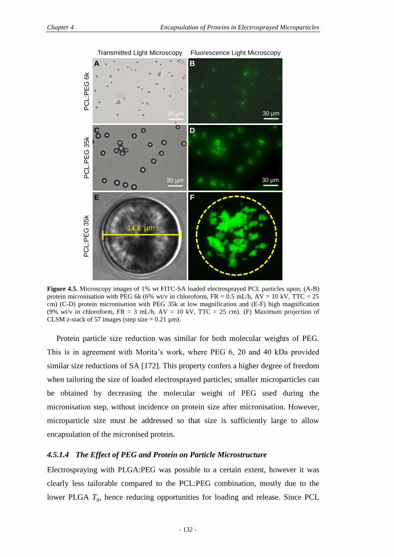
Chapter 4 Encapsulation of Proteins in Electrosprayed Microparticles
- 132 -
Figure 4.5. Microscopy images of 1% wt FITC-SA loaded electrosprayed PCL particles upon; (A-B)
protein micronisation with PEG 6k (6% wt/v in chloroform, FR = 0.5 mL/h, AV = 10 kV, TTC = 25
cm) (C-D) protein micronisation with PEG 35k at low magnification and (E-F) high magnification
(9% wt/v in chloroform, FR = 3 mL/h, AV = 10 kV, TTC = 25 cm). (F) Maximum projection of
CLSM z-stack of 57 images (step size = 0.21 µm).
Protein particle size reduction was similar for both molecular weights of PEG.
This is in agreement with Morita’s work, where PEG 6, 20 and 40 kDa provided
similar size reductions of SA [172]. This property confers a higher degree of freedom
when tailoring the size of loaded electrosprayed particles; smaller microparticles can
be obtained by decreasing the molecular weight of PEG used during the
micronisation step, without incidence on protein size after micronisation. However,
microparticle size must be addressed so that size is sufficiently large to allow
encapsulation of the micronised protein.
4.5.1.4 The Effect of PEG and Protein on Particle Microstructure
Electrospraying with PLGA:PEG was possible to a certain extent, however it was
clearly less tailorable compared to the PCL:PEG combination, mostly due to the
lower PLGA Tg, hence reducing opportunities for loading and release. Since PCL
Transmitted Light Microscopy Fluorescence Light Microscopy
PC
L:P
EG
6k
PC
L:P
EG
35
k
30 µm
PC
L:P
EG
35k
30 µm
30 µm 30 µm
14.6 µm
A B
C D
E F
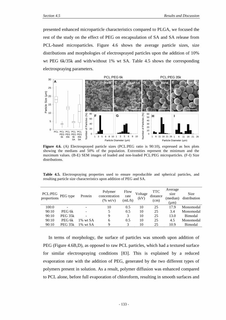
Section 4.5 Results and Discussion
- 133 -
presented enhanced microparticle characteristics compared to PLGA, we focused the
rest of the study on the effect of PEG on encapsulation of SA and SA release from
PCL-based microparticles. Figure 4.6 shows the average particle sizes, size
distributions and morphologies of electrosprayed particles upon the addition of 10%
wt PEG 6k/35k and with/without 1% wt SA. Table 4.5 shows the corresponding
electrospraying parameters.
Figure 4.6. (A) Electrosprayed particle sizes (PCL:PEG ratio is 90:10), expressed as box plots
showing the medians and 50% of the population. Extremities represent the minimum and the
maximum values. (B-E) SEM images of loaded and non-loaded PCL:PEG microparticles. (F-I) Size
distributions.
Table 4.5. Electrospraying properties used to ensure reproducible and spherical particles, and
resulting particle size characteristics upon addition of PEG and SA.
PCL:PEG
proportions PEG type Protein
Polymer
concentration
(% wt/v)
Flow
rate
(mL/h)
Voltage
(kV)
TTC
distance
(cm)
Average
size
(median)
(µm)
Size
distribution
100:0 - - 10 0.5 10 25 17.9 Monomodal
90:10 PEG 6k - 5 0.5 10 25 3.4 Monomodal
90:10 PEG 35k - 9 3 10 25 13.0 Bimodal
90:10 PEG 6k 1% wt SA 6 0.5 10 25 4.5 Monomodal
90:10 PEG 35k 1% wt SA 9 3 10 25 10.9 Bimodal
In terms of morphology, the surface of particles was smooth upon addition of
PEG (Figure 4.6B,D), as opposed to raw PCL particles, which had a textured surface
for similar electrospraying conditions [83]. This is explained by a reduced
evaporation rate with the addition of PEG, generated by the two different types of
polymers present in solution. As a result, polymer diffusion was enhanced compared
to PCL alone, before full evaporation of chloroform, resulting in smooth surfaces and
0
20
40
60
80
1 3 5 6 8 10
Nu
mb
er
of
Part
icle
s (
%)
Particle Diameter (µm)
1 3 5 6 8 10
0
5
10
15
20
25
30
PCL PCLPEG6k
PCLPEG 35k
PCLPEG6kSA
PCLPEG35kSA
Part
icle
Siz
e (
µm
)
PCL:PEG 6k PCL:PEG 35k
20 µm20 µm
A
0
10
20
30
40
50
60
1 6 11 16 21 26
Nu
mb
er
of
Part
icle
s (
%)
Particle Diameter (µm)
1 6 11 16 21 26
20 µm 20 µm 20 µm 20 µm
Blank Blank1% wt SA 1% wt SAB C D E
F G H I
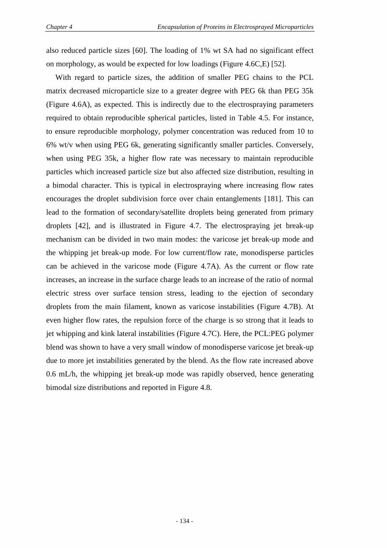
Chapter 4 Encapsulation of Proteins in Electrosprayed Microparticles
- 134 -
also reduced particle sizes [60]. The loading of 1% wt SA had no significant effect
on morphology, as would be expected for low loadings (Figure 4.6C,E) [52].
With regard to particle sizes, the addition of smaller PEG chains to the PCL
matrix decreased microparticle size to a greater degree with PEG 6k than PEG 35k
(Figure 4.6A), as expected. This is indirectly due to the electrospraying parameters
required to obtain reproducible spherical particles, listed in Table 4.5. For instance,
to ensure reproducible morphology, polymer concentration was reduced from 10 to
6% wt/v when using PEG 6k, generating significantly smaller particles. Conversely,
when using PEG 35k, a higher flow rate was necessary to maintain reproducible
particles which increased particle size but also affected size distribution, resulting in
a bimodal character. This is typical in electrospraying where increasing flow rates
encourages the droplet subdivision force over chain entanglements [181]. This can
lead to the formation of secondary/satellite droplets being generated from primary
droplets [42], and is illustrated in Figure 4.7. The electrospraying jet break-up
mechanism can be divided in two main modes: the varicose jet break-up mode and
the whipping jet break-up mode. For low current/flow rate, monodisperse particles
can be achieved in the varicose mode (Figure 4.7A). As the current or flow rate
increases, an increase in the surface charge leads to an increase of the ratio of normal
electric stress over surface tension stress, leading to the ejection of secondary
droplets from the main filament, known as varicose instabilities (Figure 4.7B). At
even higher flow rates, the repulsion force of the charge is so strong that it leads to
jet whipping and kink lateral instabilities (Figure 4.7C). Here, the PCL:PEG polymer
blend was shown to have a very small window of monodisperse varicose jet break-up
due to more jet instabilities generated by the blend. As the flow rate increased above
0.6 mL/h, the whipping jet break-up mode was rapidly observed, hence generating
bimodal size distributions and reported in Figure 4.8.
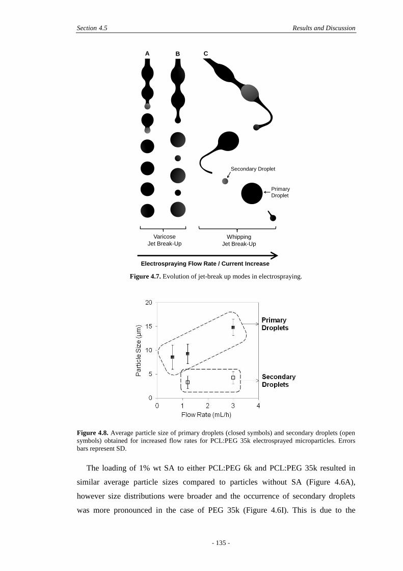
Section 4.5 Results and Discussion
- 135 -
Figure 4.7. Evolution of jet-break up modes in electrospraying.
Figure 4.8. Average particle size of primary droplets (closed symbols) and secondary droplets (open
symbols) obtained for increased flow rates for PCL:PEG 35k electrosprayed microparticles. Errors
bars represent SD.
The loading of 1% wt SA to either PCL:PEG 6k and PCL:PEG 35k resulted in
similar average particle sizes compared to particles without SA (Figure 4.6A),
however size distributions were broader and the occurrence of secondary droplets
was more pronounced in the case of PEG 35k (Figure 4.6I). This is due to the
Varicose
Jet Break-UpWhipping
Jet Break-Up
Electrospraying Flow Rate / Current Increase
Secondary Droplet
Primary
Droplet
A B C
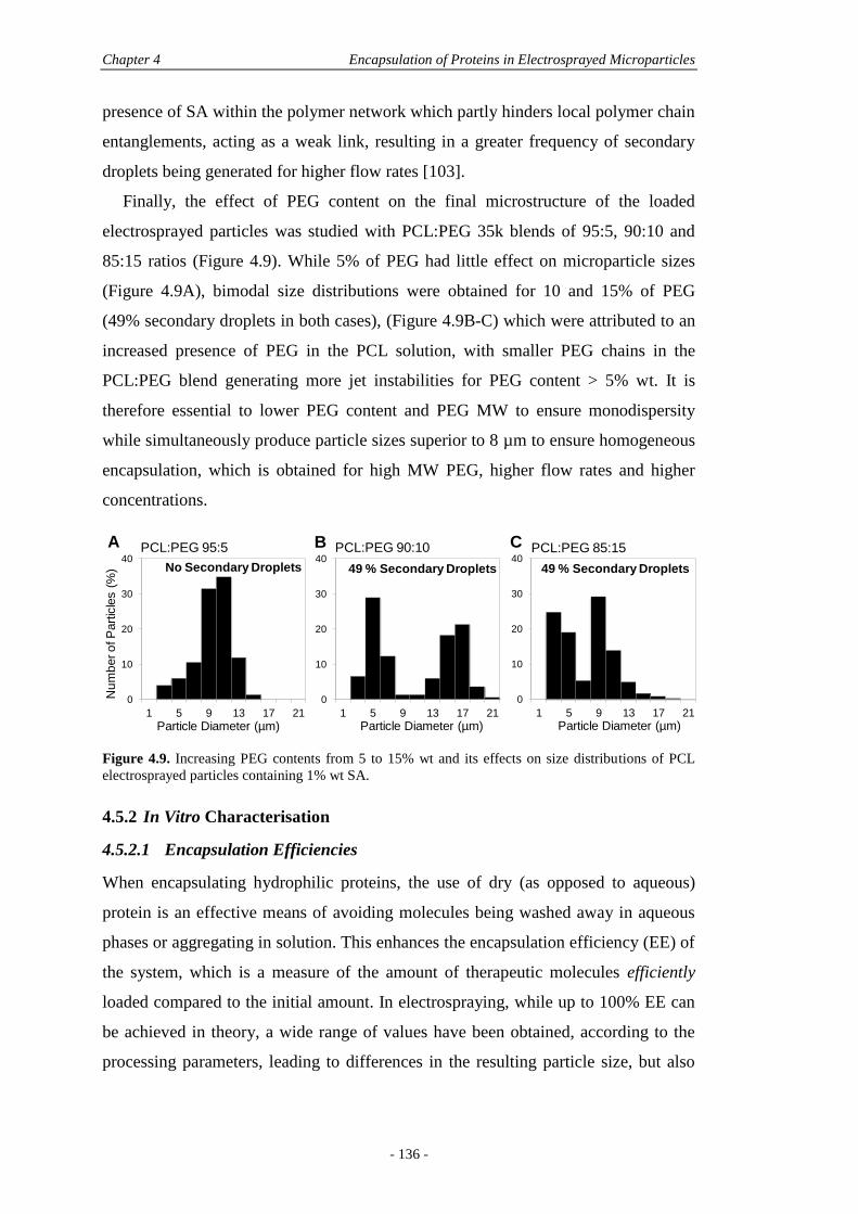
Chapter 4 Encapsulation of Proteins in Electrosprayed Microparticles
- 136 -
presence of SA within the polymer network which partly hinders local polymer chain
entanglements, acting as a weak link, resulting in a greater frequency of secondary
droplets being generated for higher flow rates [103].
Finally, the effect of PEG content on the final microstructure of the loaded
electrosprayed particles was studied with PCL:PEG 35k blends of 95:5, 90:10 and
85:15 ratios (Figure 4.9). While 5% of PEG had little effect on microparticle sizes
(Figure 4.9A), bimodal size distributions were obtained for 10 and 15% of PEG
(49% secondary droplets in both cases), (Figure 4.9B-C) which were attributed to an
increased presence of PEG in the PCL solution, with smaller PEG chains in the
PCL:PEG blend generating more jet instabilities for PEG content > 5% wt. It is
therefore essential to lower PEG content and PEG MW to ensure monodispersity
while simultaneously produce particle sizes superior to 8 µm to ensure homogeneous
encapsulation, which is obtained for high MW PEG, higher flow rates and higher
concentrations.
Figure 4.9. Increasing PEG contents from 5 to 15% wt and its effects on size distributions of PCL
electrosprayed particles containing 1% wt SA.
4.5.2 In Vitro Characterisation
4.5.2.1 Encapsulation Efficiencies
When encapsulating hydrophilic proteins, the use of dry (as opposed to aqueous)
protein is an effective means of avoiding molecules being washed away in aqueous
phases or aggregating in solution. This enhances the encapsulation efficiency (EE) of
the system, which is a measure of the amount of therapeutic molecules efficiently
loaded compared to the initial amount. In electrospraying, while up to 100% EE can
be achieved in theory, a wide range of values have been obtained, according to the
processing parameters, leading to differences in the resulting particle size, but also
0
10
20
30
40
1 5 9 13 17 21
Nu
mb
er o
f P
art
icle
s (
%)
Particle Diameter (µm)
0
10
20
30
40
1 5 9 13 17 21
Particle Diameter (µm)
0
10
20
30
40
1 5 9 13 17 21
Particle Diameter (µm)
PCL:PEG 95:5 PCL:PEG 90:10 PCL:PEG 85:15
49 % Secondary Droplets 49 % Secondary DropletsNo Secondary Droplets
A B C
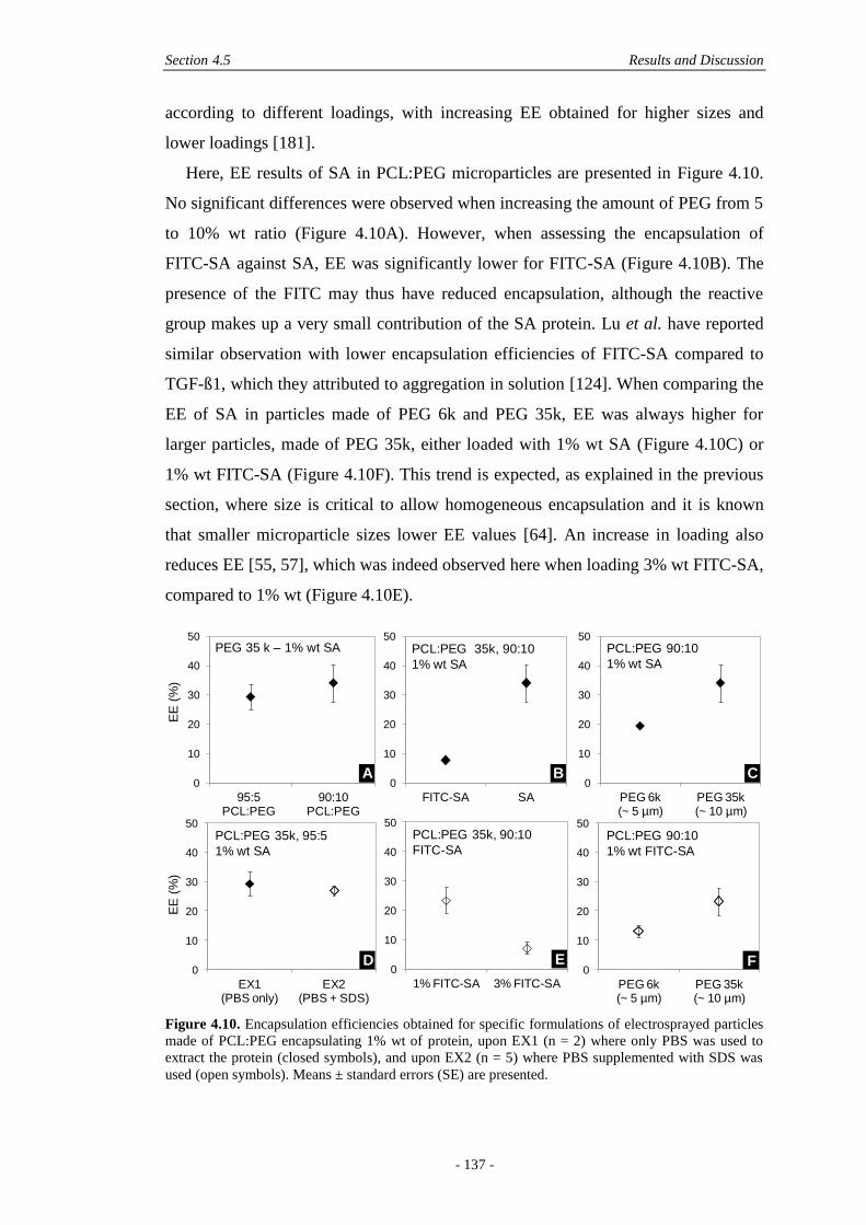
Section 4.5 Results and Discussion
- 137 -
according to different loadings, with increasing EE obtained for higher sizes and
lower loadings [181].
Here, EE results of SA in PCL:PEG microparticles are presented in Figure 4.10.
No significant differences were observed when increasing the amount of PEG from 5
to 10% wt ratio (Figure 4.10A). However, when assessing the encapsulation of
FITC-SA against SA, EE was significantly lower for FITC-SA (Figure 4.10B). The
presence of the FITC may thus have reduced encapsulation, although the reactive
group makes up a very small contribution of the SA protein. Lu et al. have reported
similar observation with lower encapsulation efficiencies of FITC-SA compared to
TGF-ß1, which they attributed to aggregation in solution [124]. When comparing the
EE of SA in particles made of PEG 6k and PEG 35k, EE was always higher for
larger particles, made of PEG 35k, either loaded with 1% wt SA (Figure 4.10C) or
1% wt FITC-SA (Figure 4.10F). This trend is expected, as explained in the previous
section, where size is critical to allow homogeneous encapsulation and it is known
that smaller microparticle sizes lower EE values [64]. An increase in loading also
reduces EE [55, 57], which was indeed observed here when loading 3% wt FITC-SA,
compared to 1% wt (Figure 4.10E).
Figure 4.10. Encapsulation efficiencies obtained for specific formulations of electrosprayed particles
made of PCL:PEG encapsulating 1% wt of protein, upon EX1 (n = 2) where only PBS was used to
extract the protein (closed symbols), and upon EX2 (n = 5) where PBS supplemented with SDS was
used (open symbols). Means ± standard errors (SE) are presented.
0
10
20
30
40
50
1% FITC-SA 3% FITC-SA
0
10
20
30
40
50
FITC-SA SA
0
10
20
30
40
50
95:5 PCL:PEG
90:10 PCL:PEG
EE
(%
)
0
10
20
30
40
50
PEG 6k (~ 5 µm)
PEG 35k(~ 10 µm)
0
10
20
30
40
50
PEG 6k(~ 5 µm)
PEG 35k(~ 10 µm)
0
10
20
30
40
50
EX1 (PBS only)
EX2(PBS + SDS)
EE
(%
)
PCL:PEG 90:10
1% wt SA
PCL:PEG 35k, 90:10
1% wt SA
PCL:PEG 35k, 95:5
1% wt SA
PCL:PEG 90:10
1% wt FITC-SA
PEG 35 k – 1% wt SA
PCL:PEG 35k, 90:10
FITC-SA
A B C
D E F
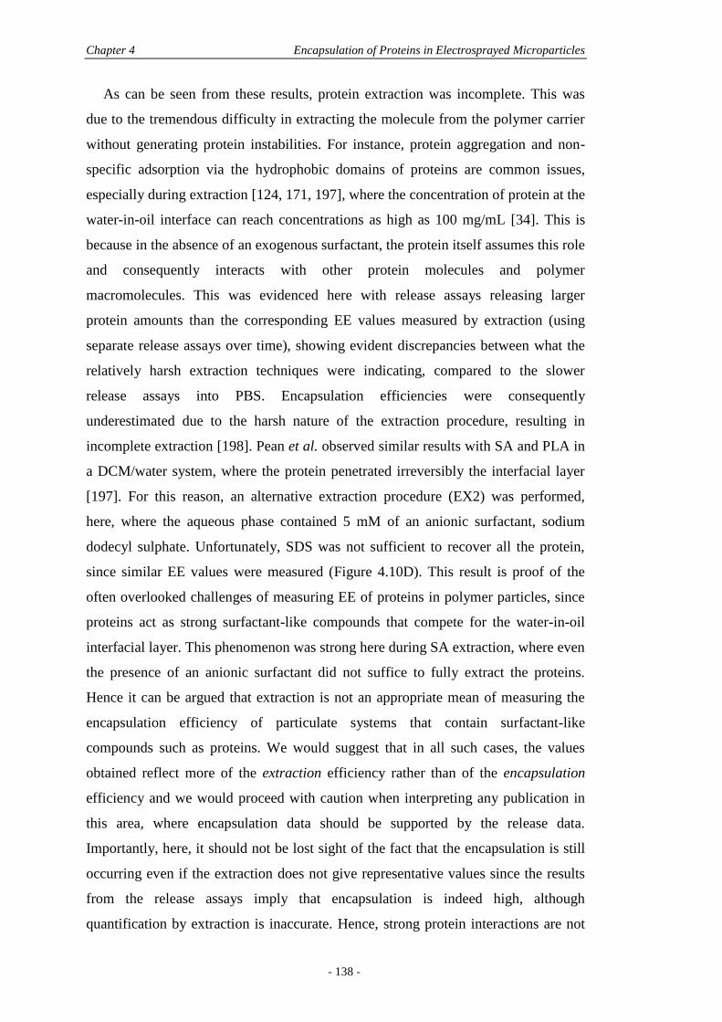
Chapter 4 Encapsulation of Proteins in Electrosprayed Microparticles
- 138 -
As can be seen from these results, protein extraction was incomplete. This was
due to the tremendous difficulty in extracting the molecule from the polymer carrier
without generating protein instabilities. For instance, protein aggregation and non-
specific adsorption via the hydrophobic domains of proteins are common issues,
especially during extraction [124, 171, 197], where the concentration of protein at the
water-in-oil interface can reach concentrations as high as 100 mg/mL [34]. This is
because in the absence of an exogenous surfactant, the protein itself assumes this role
and consequently interacts with other protein molecules and polymer
macromolecules. This was evidenced here with release assays releasing larger
protein amounts than the corresponding EE values measured by extraction (using
separate release assays over time), showing evident discrepancies between what the
relatively harsh extraction techniques were indicating, compared to the slower
release assays into PBS. Encapsulation efficiencies were consequently
underestimated due to the harsh nature of the extraction procedure, resulting in
incomplete extraction [198]. Pean et al. observed similar results with SA and PLA in
a DCM/water system, where the protein penetrated irreversibly the interfacial layer
[197]. For this reason, an alternative extraction procedure (EX2) was performed,
here, where the aqueous phase contained 5 mM of an anionic surfactant, sodium
dodecyl sulphate. Unfortunately, SDS was not sufficient to recover all the protein,
since similar EE values were measured (Figure 4.10D). This result is proof of the
often overlooked challenges of measuring EE of proteins in polymer particles, since
proteins act as strong surfactant-like compounds that compete for the water-in-oil
interfacial layer. This phenomenon was strong here during SA extraction, where even
the presence of an anionic surfactant did not suffice to fully extract the proteins.
Hence it can be argued that extraction is not an appropriate mean of measuring the
encapsulation efficiency of particulate systems that contain surfactant-like
compounds such as proteins. We would suggest that in all such cases, the values
obtained reflect more of the extraction efficiency rather than of the encapsulation
efficiency and we would proceed with caution when interpreting any publication in
this area, where encapsulation data should be supported by the release data.
Importantly, here, it should not be lost sight of the fact that the encapsulation is still
occurring even if the extraction does not give representative values since the results
from the release assays imply that encapsulation is indeed high, although
quantification by extraction is inaccurate. Hence, strong protein interactions are not
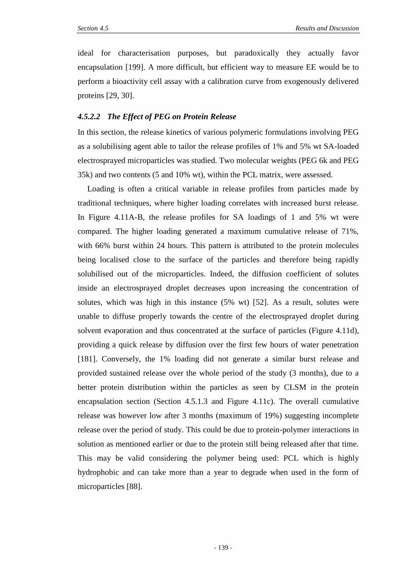
Section 4.5 Results and Discussion
- 139 -
ideal for characterisation purposes, but paradoxically they actually favor
encapsulation [199]. A more difficult, but efficient way to measure EE would be to
perform a bioactivity cell assay with a calibration curve from exogenously delivered
proteins [29, 30].
4.5.2.2 The Effect of PEG on Protein Release
In this section, the release kinetics of various polymeric formulations involving PEG
as a solubilising agent able to tailor the release profiles of 1% and 5% wt SA-loaded
electrosprayed microparticles was studied. Two molecular weights (PEG 6k and PEG
35k) and two contents (5 and 10% wt), within the PCL matrix, were assessed.
Loading is often a critical variable in release profiles from particles made by
traditional techniques, where higher loading correlates with increased burst release.
In Figure 4.11A-B, the release profiles for SA loadings of 1 and 5% wt were
compared. The higher loading generated a maximum cumulative release of 71%,
with 66% burst within 24 hours. This pattern is attributed to the protein molecules
being localised close to the surface of the particles and therefore being rapidly
solubilised out of the microparticles. Indeed, the diffusion coefficient of solutes
inside an electrosprayed droplet decreases upon increasing the concentration of
solutes, which was high in this instance (5% wt) [52]. As a result, solutes were
unable to diffuse properly towards the centre of the electrosprayed droplet during
solvent evaporation and thus concentrated at the surface of particles (Figure 4.11d),
providing a quick release by diffusion over the first few hours of water penetration
[181]. Conversely, the 1% loading did not generate a similar burst release and
provided sustained release over the whole period of the study (3 months), due to a
better protein distribution within the particles as seen by CLSM in the protein
encapsulation section (Section 4.5.1.3 and Figure 4.11c). The overall cumulative
release was however low after 3 months (maximum of 19%) suggesting incomplete
release over the period of study. This could be due to protein-polymer interactions in
solution as mentioned earlier or due to the protein still being released after that time.
This may be valid considering the polymer being used: PCL which is highly
hydrophobic and can take more than a year to degrade when used in the form of
microparticles [88].
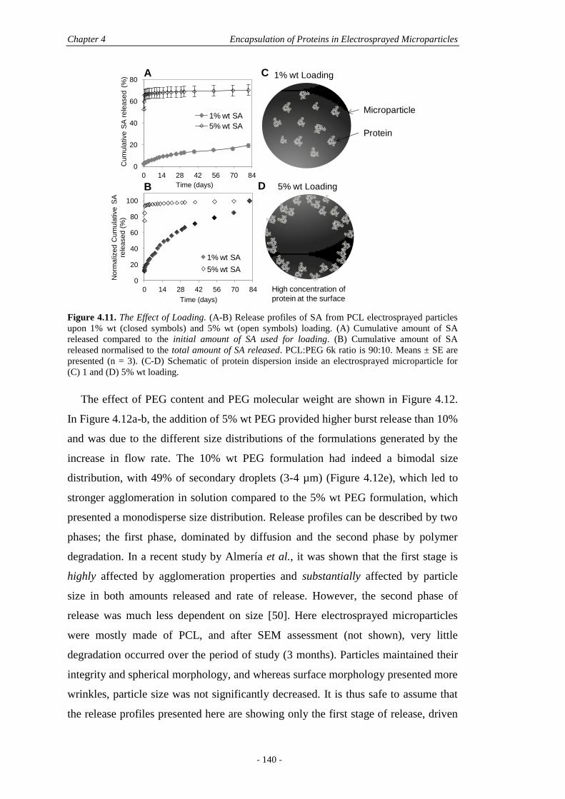
Chapter 4 Encapsulation of Proteins in Electrosprayed Microparticles
- 140 -
Figure 4.11. The Effect of Loading. (A-B) Release profiles of SA from PCL electrosprayed particles
upon 1% wt (closed symbols) and 5% wt (open symbols) loading. (A) Cumulative amount of SA
released compared to the initial amount of SA used for loading. (B) Cumulative amount of SA
released normalised to the total amount of SA released. PCL:PEG 6k ratio is 90:10. Means ± SE are
presented (n = 3). (C-D) Schematic of protein dispersion inside an electrosprayed microparticle for
(C) 1 and (D) 5% wt loading.
The effect of PEG content and PEG molecular weight are shown in Figure 4.12.
In Figure 4.12a-b, the addition of 5% wt PEG provided higher burst release than 10%
and was due to the different size distributions of the formulations generated by the
increase in flow rate. The 10% wt PEG formulation had indeed a bimodal size
distribution, with 49% of secondary droplets (3-4 µm) (Figure 4.12e), which led to
stronger agglomeration in solution compared to the 5% wt PEG formulation, which
presented a monodisperse size distribution. Release profiles can be described by two
phases; the first phase, dominated by diffusion and the second phase by polymer
degradation. In a recent study by Almería et al., it was shown that the first stage is
highly affected by agglomeration properties and substantially affected by particle
size in both amounts released and rate of release. However, the second phase of
release was much less dependent on size [50]. Here electrosprayed microparticles
were mostly made of PCL, and after SEM assessment (not shown), very little
degradation occurred over the period of study (3 months). Particles maintained their
integrity and spherical morphology, and whereas surface morphology presented more
wrinkles, particle size was not significantly decreased. It is thus safe to assume that
the release profiles presented here are showing only the first stage of release, driven
0
20
40
60
80
100
0 14 28 42 56 70 84
Norm
aliz
ed C
um
ula
tive S
A
rele
ased
(%
)
Time (days)
1% wt SA
5% wt SA
0
20
40
60
80
0 14 28 42 56 70 84
Cum
ula
tive S
A r
ele
ased (
%)
Time (days)
1% wt SA
5% wt SA
High concentration of
protein at the surface
Microparticle
Protein
1% wt Loading
5% wt Loading
A
B
C
D
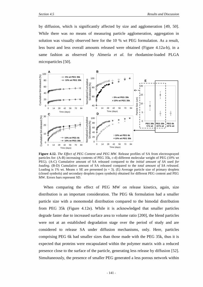
Section 4.5 Results and Discussion
- 141 -
by diffusion, which is significantly affected by size and agglomeration [49, 50].
While there was no means of measuring particle agglomeration, aggregation in
solution was visually observed here for the 10 % wt PEG formulation. As a result,
less burst and less overall amounts released were obtained (Figure 4.12a-b), in a
same fashion as observed by Almería et al. for rhodamine-loaded PLGA
microparticles [50].
Figure 4.12. The Effect of PEG Content and PEG MW. Release profiles of SA from electrosprayed
particles for: (A-B) increasing contents of PEG 35k, c-d) different molecular weight of PEG (10% wt
PEG). (A-C) Cumulative amount of SA released compared to the initial amount of SA used for
loading. (B-D) Cumulative amount of SA released compared to the total amount of SA released.
Loading is 1% wt. Means ± SE are presented (n = 3). (E) Average particle size of primary droplets
(closed symbols) and secondary droplets (open symbols) obtained for different PEG content and PEG
MW. Errors bars represent SD.
When comparing the effect of PEG MW on release kinetics, again, size
distribution is an important consideration. The PEG 6k formulation had a smaller
particle size with a monomodal distribution compared to the bimodal distribution
from PEG 35k (Figure 4.12e). While it is acknowledged that smaller particles
degrade faster due to increased surface area to volume ratio [200], the blend particles
were not at an established degradation stage over the period of study and are
considered to release SA under diffusion mechanisms, only. Here, particles
comprising PEG 6k had smaller sizes than those made with the PEG 35k, thus it is
expected that proteins were encapsulated within the polymer matrix with a reduced
presence close to the surface of the particle, generating less release by diffusion [52].
Simultaneously, the presence of smaller PEG generated a less porous network within
0
5
10
15
20
PEG 35k5 % wt
PEG 35k10 % wt
PEG 6k10 % wt
Part
icle
Siz
e (
um
)
0
10
20
30
0 14 28 42 56 70 84Cum
ula
tive S
A rele
ased (
%)
Time (days)
10% wt PEG 6k
10% wt PEG 35k 0
20
40
60
80
100
0 14 28 42 56 70 84
Norm
aliz
ed C
um
ula
tive
SA
rele
ased (
%)
Time (days)
10% wt PEG 6k
10% wt PEG 35k
0
20
40
60
80
100
0 14 28 42 56 70 84
Cum
ula
tive S
A rele
ased (
%)
Time (days)
5% wt PEG 35k
10% wt PEG 35k
40
60
80
100
0 14 28 42 56 70 84
Norm
aliz
ed C
um
ula
tive
SA
rele
ased (
%)
Time (days)
5% wt PEG 35k
10% wt PEG 35k
A B
C D
E
Chapter 4 Encapsulation of Proteins in Electrosprayed Microparticles
- 142 -
the microparticles, thus reducing the initial burst release of larger protein molecules.
Hence, while overall release was low with PEG 6k, it reached the same amount as
with PEG 35k at 84 days and was sustained over the period of study, with no initial
burst release. Importantly, release had not reached a plateau after 84 days, suggesting
further potential release by degradation (Figure 4.12c-d).
These results suggest that the use of PEG in a microparticle system is not
sufficient to control release kinetics, but involves a complex combination of other
parameters. Compared to traditional fabrication techniques, the influence of PEG has
often shown controversial trends; the amount of PEG is more determinant than a
change in PEG MW, but still less significant than a change in matrix MW (PLGA)
[127], and while PEG is usually known to increase burst release, PEG has also been
shown to decrease cumulative release, due to a more acidic pH resulting in more
protein aggregation in solution [124]. Here, in electrosprayed microparticles, it could
be concluded that a lower MW PEG was efficient in reducing burst release, however
protein-polymer interactions impaired complete release, for any formulation type.
Importantly, release kinetics were a result of the particle size characteristics obtained
from different processing parameters required to electrospray microparticles with
PEG to maintain spherical and reproducible morphology. While a smaller particle led
to reduced burst release, a threshold size needs to be met to allow homogenous
encapsulation of protein, and bimodal size distributions, which can be generated for
too high PEG content or high electrospraying flow rate, can lead to particle
aggregation in solution and decreased cumulative release.
4.6 CONCLUSIONS
In conclusion, we demonstrated here that micronised proteins could be
homogeneously encapsulated in electrosprayed polymeric particles using a non-
aqueous route. The presence of PEG within the electrosprayed microparticle matrix
provided a tight control over the characteristics of particles, with PEG content and
MW but also with electrospraying flow rate. Low protein loading, micronisation with
PEG 6k, particle monodispersity and moderate microparticle sizes were efficient in
providing homogeneous encapsulation, and sustained and burst-free release of SA
from PCL particles up to 84 days. Conversely, PEG 35k allowed for burst release
within 3 days. The results presented here are of particular importance for the delivery
Section 4.7 Acknowledgements
- 143 -
of growth factors in tissue engineering applications, since growth factors are
sensitive molecules requiring different types of delivery, from burst to sustained
delivery, according to their function. For instance, a quick delivery of VEGF is
known to be essential at the early stages of bone repair while a more sustained
delivery of bone morphogenetic proteins is required throughout the process. The
possibility of dry encapsulation and the control of encapsulation and release profiles
obtained here by electrospraying and PEG as a micronising and solubilising agent
may thus be well-suited to address the requirements of growth factor delivery
therapies.
4.7 ACKNOWLEDGEMENTS
The authors would like to thank L.-J. Vandi (University of Queensland) for helpful
discussion on Hansen Solubility Parameter, Dr. Christina Theodoropoulos (QUT) for
help with SEM imaging, Dr. Leonore de Boer (QUT) for help with CLSM imaging.
Thanks to the ARC (Discovery grant no. DP0989000) for financial support.

- 145 -
Chapter 5: Growth Factors Loaded into
Electrosprayed Microparticles:
Detection and Bioactivity Discrepancies
with In Vitro Assays
Nathalie Bock1,2,3
, Tim R. Dargaville1, Giles T. S. Kirby
2, Dietmar W.
Hutmacher3, Maria A. Woodruff
2
Manuscript submitted
© 2014 Nathalie Bock, all rights reserved
Statement of contribution of co-authors for thesis by published papers
Contributors Statement of contribution
Nathalie Bock Developed the research questions
Designed and performed the experiments
Analysed and interpreted the results
Conceived and wrote the manuscript
Tim R. Dargaville* Involved in the conception of the project
Provided feedback on manuscript
Giles T. S. Kirby* Provided technical guidance with cell assays
Assisted in DNA quantification
Dietmar W. Hutmacher* Involved in the conception of the project
Provided feedback on manuscript
Maria A. Woodruff* Involved in the conception of the project
Provided feedback on manuscript
1 Tissue Repair and Regeneration Group
2 Biomaterials and Tissue Morphology Group
3 Regenerative Medicine Group
Institute of Health and Biomedical Innovation, Queensland University of Technology,
60 Musk Avenue, Kelvin Grove, QLD 4059, Australia
Chapter 5 In Vitro Release, Detection and Bioactivity of Growth Factors
- 146 -
The authors listed above have certified* that:
1. they meet the criteria for authorship in that they have participated in the
conception, execution, or interpretation, of at least that part of the publication in
their field of expertise;
2. they take public responsibility for their part of the publication, except for the
responsible author who accepts overall responsibility for the publication;
3. there are no other authors of the publication according to these criteria;
4. potential conflicts of interest have been disclosed to (a) granting bodies, (b) the
editor or publisher of journals or other publications, and (c) the head of the
responsible academic unit, and
5. they agree to the use of the publication in the student’s thesis and its publication
on the QUT ePrints database consistent with any limitations set by publisher
requirements.
Principal Supervisor Confirmation
I have sighted email or other correspondence from all Co-authors confirming their
certifying authorship.
Section 5.1 Abstract
- 147 -
5.1 ABSTRACT
Purpose To provide an efficient growth factor (GF) delivery system that
maintains GF activity and to assess current in vitro means for GF activity
quantification.
Methods Vascular endothelial growth factor (VEGF) and bone morphogenetic
protein 7 (BMP-7) were encapsulated in poly(lactic-co-glycolic acid) (PLGA)
electrosprayed microparticles with poly(ethylene glycol) (PEG) and trehalose, to
assist GF bioactivity. Typical quantification procedures, such as extraction and
release assays using saline buffer were compared with cell bioactivity assays.
Results Saline assays showed that quantification procedures generated a
significant degree of GF interactions, impairing accurate assessment by ELISA
assays, although this shortfall was partially addressed by the use of surfactants in
solution. When both dry BMP-7 and VEGF were vortexed with chloroform, as is the
case during the electrospraying process, reduced concentrations were measured by
ELISA, but the biological effect on myoblast cells (C2C12) or endothelial cells
(HUVECs) was unaffected. When electrosprayed particles containing BMP-7 were
cultured with pre-osteoblasts (MC3T3-E1), significant cell differentiation, assessed
with alkaline phosphatase activity, was observed up to three weeks, contrary to that
predicted by assays in PBS.
Conclusions Electrosprayed particles ensured efficient delivery of fully active GFs
and major discrepancies in quantifying GFs in microparticle systems were
highlighted, when comparing ELISA with cell-based assays.
5.2 KEYWORDS
Bioactivity, bone morphogenetic protein 7, enzyme-linked immunosorbent assay,
electrospraying, microparticles.
5.3 INTRODUCTION
Formulations for the controlled release of therapeutics have been in the spotlight of
the biotechnology industry for many years, and while robust, low molecular weight
drugs have extensively been addressed, developing similar systems for proteins has
proven more challenging [34]. Protein therapeutics are increasingly being explored

Chapter 5 In Vitro Release, Detection and Bioactivity of Growth Factors
- 148 -
and utilised within the field of tissue engineering (TE), since many mechanisms
involved in tissue regeneration are driven by proteins, which need to be delivered
efficiently for maximum benefit [6, 147]. However, development of controlled
release formulations for proteins faces many challenges, due to the relatively large
and complex architecture of most proteins, which incorporate hydrophilic and
hydrophobic domains with numerous reactive groups [171, 176]. The unfolding of
polypeptide chains can expose hydrophobic groups which can interact with other
molecules (aggregation) and with hydrophobic matrices (non-specific adsorption)
(Figure 5.1A) [124, 197, 201]. Hence, proteins are challenging molecules to
encapsulate and deliver from polymeric carriers, but also difficult to quantify. It is in
fact paramount to understand that, while protein encapsulation and in vivo delivery
may be affected by protein denaturation, in vitro experimental conditions and
characterisation methods also account for a significant part of denaturation, leading
to underestimated protein quantification, a vast issue in the field [176]. With this in
mind, two objectives can be set: One is to provide a sustained release formulation
with full preservation of the protein’s native state and the other is to use
representative assays that accurately assess the formulation, both ambitious goals.
In order to address the first objective, protein-carrier formulations require
strategies to preserve the native state and low immunogenicity of proteins [34].
When considering biodegradable polymeric particles, solid encapsulation has
become a superior option compared to aqueous incorporation, which requires a
water-in-oil (w/o) emulsion, and is accepted as a potent cause of protein denaturation
[35] due to the w/o interfacial tension causing protein molecules to unfold [171]. By
using a solid encapsulation process, such as spray-drying or solid emulsion, the
bioactivity of several proteins was improved or maintained [121, 179]. Stabilisers
can also be used to protect proteins [127], by either providing a microenvironment
that reduces the free energy of protein molecules or increases the energy barrier
between the native and denatured states [171]. Micronisation of the protein with
poly(ethylene glycol) (PEG) upon co-lyophilisation [172] and prior to encapsulation,
can effectively lead to a more favorable state of the protein [174-176], as seen for
nerve growth factor [123] and albumin [175], and reduces protein adsorption to the
polymer matrix [176, 197]. Alternatively, the use of saccharides is another approach
to protect proteins [171, 201, 202]. Sugars are small osmolyte molecules which
stabilise proteins via preferential hydration of the native form by hydrogen bonding
Section 5.3 Introduction
- 149 -
during lyophilisation [34, 201] and were shown to protect growth factors (GF) [203]
and proteins [31]. Since low molecular weight sugars dissolve rapidly and are not
retained within the polymer carrier, the presence of PEG would be paramount in
protecting proteins from adsorption onto the polymer matrix once released [171].
Protein denaturation is a key limitation of traditional encapsulation techniques and
has limited the clinical translation. Electrospraying of polymers with therapeutic
molecules is an emerging technique which has been shown to maintain the
bioactivity of some proteins and GFs, including insulin-like GF 1 (IGF-1) [29],
platelet-derived GF (PDGF) [30], transforming GF ß-3 (TGFß-3) and bone
morphogenetic protein 6 (BMP-6) [31]. Although PEG and sugars blended into the
matrix have been widely used for improving protein bioactivity in traditional
techniques [123, 171, 174-176, 199], no studies have investigated their use in
electrospraying.
Further to providing an optimised protein-carrier formulation, accurate
quantification of active proteins is the next challenge. Several techniques can assess
protein denaturation and inform on structural and conformational changes, size and
shape distributions [204]. When encapsulating a protein in a polymeric device,
however, it becomes difficult to assess the protein conformation after extraction or
release in buffer, since irreversible changes can be induced by the processes
themselves (Figure 5.1B) [205]. Buffer saline release conditions, for instance, often
presents an acidic pH and destabilising factors that impair accurate evaluation of
release kinetics. This has been long demonstrated in the literature where polyester-
based microparticles almost always present incomplete release profiles [176] when
assessed with enzyme linked immunosorbent assays (ELISA) and simple protein
assays. The study of GF activity is, hence, more relevant when cell-based assays are
used, which are the best indicator of GF bioactivity. Changes in cell proliferation or
differentiation upon exposure to ‘active’ GFs can be evaluated [181].

Chapter 5 In Vitro Release, Detection and Bioactivity of Growth Factors
- 150 -
Figure 5.1. Schematic description of: (A) growth factor interactions in solution, via hydrophobic
domains (adapted from [171]), and (B) concentration of GF complexes at the water-in-oil interface
upon an extraction procedure.
In order to address the two important challenges of encapsulation and assessment,
we have evaluated two complementary GFs used in bone tissue engineering; bone
morphogenetic protein 7 (BMP-7) and vascular endothelial GF (VEGF) for
encapsulation using an electrospraying technique and assessed the potential of PEG
and trehalose as protective additives within the formulation. We have indeed shown
for the first time, in our previous work, homogeneous loading of micronised proteins
with PEG in electrosprayed polyester particles, and obtained tight control over
particles characteristics [206], making PEG a legitimate choice for further
assessment as a protective agent for GF bioactivity. Here, we have assessed GF
bioactivity at various stages of the encapsulation process with typical buffer assays
using ELISA and compared the results with actual bioactivity results from cell
assays. A direct contact assay of GF-loaded particles with cells was also used to
evaluate the efficiency of the delivery system, and provided key findings regarding
the quantification of GFs in microparticle systems using fundamentally different
assays.
Hydrophilic domains
Hydrophobic domains
Growth Factor (GF)
Hydrophobic
polymer
Non-specific adsorption
Organic droplet
Aqueous droplet
Aqueous phase
Organic phasePolymer chain
GF
Aqueous phase
Organic phase
High concentra-
tion of adsorbed/
aggregated GF
Adsorbed GF-
polymer complex
Covalent/non-covalent aggregation
Aggregated
GF complex
A
B
Section 5.4 Experimental Section
- 151 -
5.4 EXPERIMENTAL SECTION
5.4.1 Materials
Poly(lactic-co-glycolic acid) (PLGA) 85:15 (Mn 41.3 kDa, PDI 1.6) was purchased
from Evonik Industries. Poly(ethylene glycol) (PEG) with Mn = 35 kDa, trehalose,
chloroform, dichloromethane (DCM), polysorbate 20 (PS20), sodium dodecyl
sulphate (SDS), and human serum albumin (SA) were purchased from Sigma-
Aldrich. Recombinant vascular endothelial growth factor (VEGF) was purchased
from ProsSpec-Tany TechnoGene Ltd. via BioNovus Life Sciences. Recombinant
human bone morphogenetic protein-7 (BMP-7) was generously donated by Stryker.
5.4.2 Particle Fabrication
Either SA alone or GF:SA were first micronised to ensure protein particle size
reduction, prior to electrospraying [127, 172, 177]. Aqueous solutions were prepared,
containing SA and PEG, with and without GF, and with and without trehalose. The
GF:SA and (GF:SA):PEG part ratios were maintained at 1:9 and 1:10, respectively
(Table 5.1) [172]. Samples were dissolved in 0.2 µm filtered doubly distilled water
(1 mL) and frozen by immersion in liquid nitrogen. After freeze-drying, PLGA was
dissolved in chloroform and added to the lyophilised GF under magnetic stirring. The
resultant dispersions were probe sonicated for 1 min at 0.5 W (Misonix 3,000). The
final polymer (PLGA:PEG) content was 11% wt/v for a PLGA:PEG part ratio of 9:1.
The dispersions were immediately loaded into 1 mL glass syringes, fitted with a 21 G
stainless steel nozzle and electrosprayed. The dispersions were extruded at a rate of
0.8 mL/h using a syringe pump (World Precision Instruments) and a voltage of 10
kV was applied to the needle tip. The tip-to-collector (TTC) distance was 15 cm and
collectors consisted of aluminium foils (15 × 15 cm2) sterilised with 70% ethanol.
After electrospraying, collectors were placed under vacuum for a further 72 hours.
The microparticles were transferred into glass vials and stored at -18°C until further
analysis.
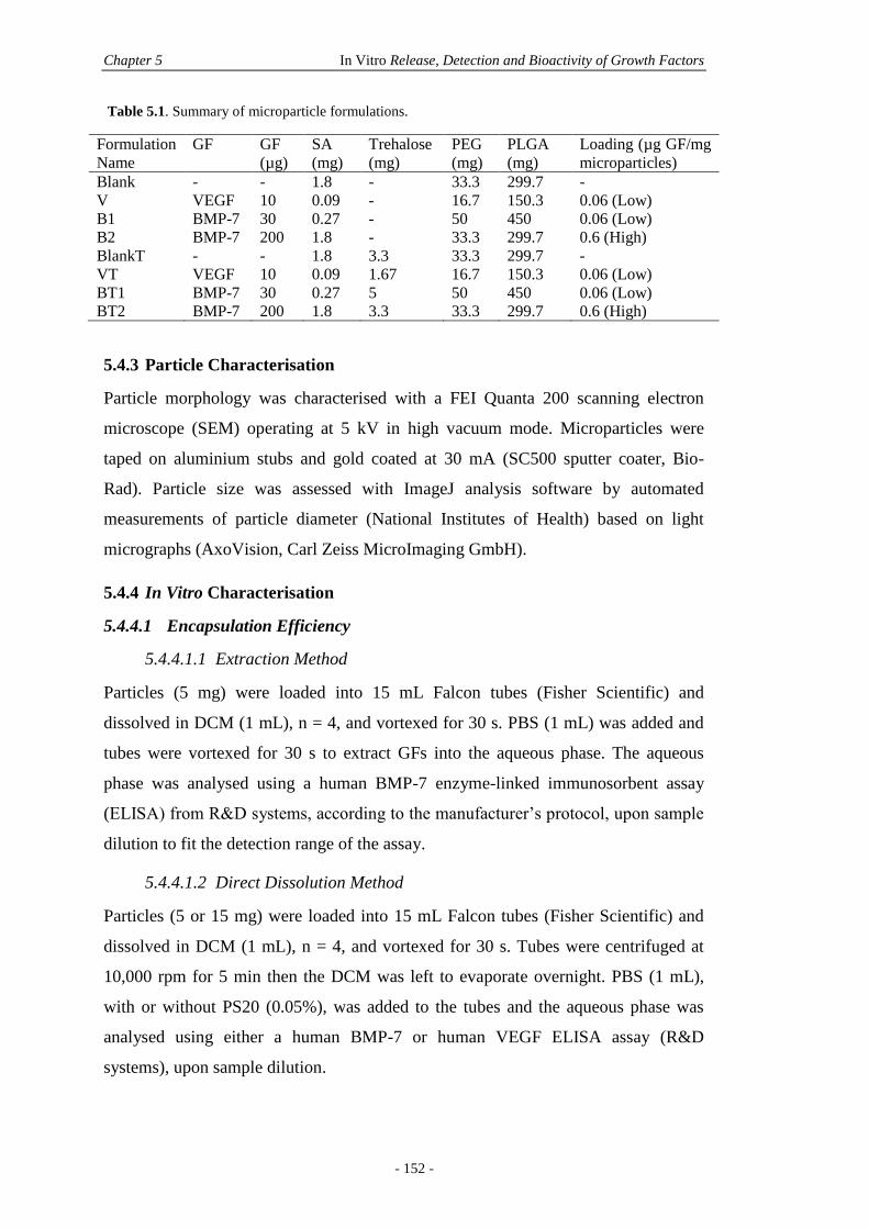
Chapter 5 In Vitro Release, Detection and Bioactivity of Growth Factors
- 152 -
Table 5.1. Summary of microparticle formulations.
Formulation
Name
GF GF
(µg)
SA
(mg)
Trehalose
(mg)
PEG
(mg)
PLGA
(mg)
Loading (µg GF/mg
microparticles)
Blank - - 1.8 - 33.3 299.7 -
V VEGF 10 0.09 - 16.7 150.3 0.06 (Low)
B1 BMP-7 30 0.27 - 50 450 0.06 (Low)
B2 BMP-7 200 1.8 - 33.3 299.7 0.6 (High)
BlankT - - 1.8 3.3 33.3 299.7 -
VT VEGF 10 0.09 1.67 16.7 150.3 0.06 (Low)
BT1 BMP-7 30 0.27 5 50 450 0.06 (Low)
BT2 BMP-7 200 1.8 3.3 33.3 299.7 0.6 (High)
5.4.3 Particle Characterisation
Particle morphology was characterised with a FEI Quanta 200 scanning electron
microscope (SEM) operating at 5 kV in high vacuum mode. Microparticles were
taped on aluminium stubs and gold coated at 30 mA (SC500 sputter coater, Bio-
Rad). Particle size was assessed with ImageJ analysis software by automated
measurements of particle diameter (National Institutes of Health) based on light
micrographs (AxoVision, Carl Zeiss MicroImaging GmbH).
5.4.4 In Vitro Characterisation
5.4.4.1 Encapsulation Efficiency
5.4.4.1.1 Extraction Method
Particles (5 mg) were loaded into 15 mL Falcon tubes (Fisher Scientific) and
dissolved in DCM (1 mL), n = 4, and vortexed for 30 s. PBS (1 mL) was added and
tubes were vortexed for 30 s to extract GFs into the aqueous phase. The aqueous
phase was analysed using a human BMP-7 enzyme-linked immunosorbent assay
(ELISA) from R&D systems, according to the manufacturer’s protocol, upon sample
dilution to fit the detection range of the assay.
5.4.4.1.2 Direct Dissolution Method
Particles (5 or 15 mg) were loaded into 15 mL Falcon tubes (Fisher Scientific) and
dissolved in DCM (1 mL), n = 4, and vortexed for 30 s. Tubes were centrifuged at
10,000 rpm for 5 min then the DCM was left to evaporate overnight. PBS (1 mL),
with or without PS20 (0.05%), was added to the tubes and the aqueous phase was
analysed using either a human BMP-7 or human VEGF ELISA assay (R&D
systems), upon sample dilution.
Section 5.4 Experimental Section
- 153 -
5.4.4.2 Growth Factor Recovery through In Vitro Processing
Using the extraction and direct dissolution procedures stated above, the recovery of
VEGF with and without the presence of unloaded PLGA microparticles was
investigated. A 250 ng/mL VEGF solution (1 mL) (containing 0.1% wt SA) was
lyophilised with and without unloaded microparticles (5 mg), n = 3. The mixtures
were then subjected to the EX or DD procedures and the aqueous phases were
analysed using ELISA, after sample dilution. For BMP-7, recovery upon freeze-
drying and EX procedure that contained surfactants was assessed. Three aqueous
solutions were prepared: PBS, PBS + PS20 (0.05%) and PBS + SDS (0.05%). A 600
ng/mL BMP-7 solution (1 mL) (containing 0.1% wt SA) was lyophilised with and
without unloaded microparticles (5 mg), n = 3. The mixtures were then subjected to
the EX procedure with the various aqueous solutions and the aqueous phases were
analysed using ELISA, after sample dilution. Controls consisted of reconstituted GFs
following freeze-drying, in the same aqueous solutions.
5.4.4.3 In Vitro Release
Particles (10 mg) were placed in 2 mL screw-capped high purity polypropylene
microtubes (Sarstedt), supplemented with the release solution; PBS or PBS + PS20
(0.05%), (1.5 mL). Tubes were agitated at a speed of 8 rpm at 37°C. At specific time
points, microtubes were removed from the incubator and agitation was stopped. After
allowing for natural particle settlement at the bottom of microtubes, the supernatant
(1.3 mL) was collected and replaced by the same amount of fresh release solution.
Supernatants were immediately stored at -20°C for further analysis using ELISA
assays.
5.4.4.4 Growth Factor Bioactivity
5.4.4.4.1 HUVEC Proliferation Assay
The bioactivity of VEGF after micronisation with PEG, SA, trehalose and contact
with organic solvent was studied in vitro with an optimised human umbilical vein
endothelial cell (HUVEC) proliferation assay (section 5.9.1.1, supporting
information). The growth medium consisted of Dulbecco's modified Eagle medium
(DMEM) F12-K nutrient mixture (Invitrogen), 0.1 mg/mL heparin (Sigma), 0.05
mg/mL endothelial cell growth supplement (ECGS) (Millipore), 10% foetal calf
serum (FCS) and 1% penicillin/streptomycin (P/S) (both from Invitrogen). Each
processed VEGF was reconstituted in PBS before assessment with HUVECs, except
Chapter 5 In Vitro Release, Detection and Bioactivity of Growth Factors
- 154 -
for one treatment that included vortexing the VEGF lyophilisate with chloroform, in
order to mimic the process of solid GF dispersion in organic solvent that is
undertaken prior to electrospraying. The solvent was left to evaporate overnight,
before re-dissolution in PBS. A 96-well plate was gelatin-coated and 8,000 cells/well
were seeded. The culture medium contained no ECGS and contained only 5% FCS.
On the first treatment day (24 hours after initial cell seeding and culture in growth
medium), 150 µL of culture medium and 50 µL of VEGF treatments or controls were
added to each well, for a VEGF concentration of 12 ng/mL per well. Cells were then
cultured for 3 days without media change followed by medium removal and freezing
for 48 h, n = 6. After treatment with Proteinase K (Sigma), DNA content was
analysed with the PicoGreen® assay (Invitrogen), according to the manufacturer’s
protocol. In parallel, VEGF concentrations were also measured by ELISA (n = 4).
5.4.4.4.2 C2C12 Differentiation Assay
The bioactivity of BMP-7 was evaluated in vitro using a mouse myoblast cell
(C2C12) differentiation assay. Cells were cultured in DMEM medium (Invitrogen)
supplemented with 10% FCS and 1% P/S. Concentrations of 5,000 cells/well were
seeded in a 48-well plate and incubated for 24 h. First, the effect of BMP-7 dose on
cell proliferation and cell differentiation was studied using doses ranging from 0.7 to
3.3 µg/mL of BMP-7 (section 5.9.1.2, supporting information). Subsequently, the
effect of freeze-drying of BMP-7 (1.4 µg in 1 mL) alone and in the presence of PEG,
SA and trehalose was assessed. In addition, the effect of chloroform was studied by
vortexing the BMP-7 lyophilisate with chloroform and letting the solvent evaporate
overnight, before re-dissolution in PBS (1 mL) and addition to C2C12 cells. The
various treatments were given on day 1, which was replaced by fresh medium
containing identical treatments on day 3. All treatments were removed on day 5 and
cells frozen for 48 h. The number of replicates was 12 per condition, 6 replicates
were used for DNA content quantification by a PicoGreen® assay (Invitrogen) after
Proteinase K treatment (Sigma), and 6 replicates were used for quantification of
alkaline phosphatase (ALP) expression. This latter was measured by adding para-
nitrophenyl phosphate (pNPP) (Sigma) to cells, which is converted to p-nitrophenol
(pNP). The absorbance of pNP was measured at 405 nm with a spectrophotometer
(Bio-Rad). In parallel, the concentrations of BMP-7 were also measured by ELISA
(n = 3).
Section 5.4 Experimental Section
- 155 -
5.4.4.5 In Vitro Microparticle 2D Culture
The ability of PLGA microparticle formulations to deliver active BMP-7 was
assessed via an in vitro direct contact culture with murine calvaria pre-ostoblast
(MC3T3-E1) cells over 3 weeks. High BMP-7 loading formulations were selected
(B2 and B2T, Table 5.1) to probe for an effect from the trehalose. Microparticles that
did not contain BMP-7 were used as a negative control. Cells were cultured in α-
minimum essential medium (α-MEM) supplemented with 10% FCS and 1% P/S as
the standard growth media for all experimental conditions, except the positive
control 1 (PC1), which contained osteogenic media and included 10 mM β-
glycerophosphate, 0.1 mM ascorbate-2-phosphate and 100 nM dexamethasone in
standard growth media. Concentrations of 20,000 cells/well were seeded in 24-well
plates and incubated with growth media for 24h. On the experimental start day,
media was aspirated and cells were treated with different conditions (1 mL, n = 36, N
= 288) summarised in Table 5.2. Briefly, 2.5 mg of microparticles/well were
selected, representing a maximum of 1.5 µg BMP-7, assuming a 100% loading in
microparticles. Two positive controls were used which comprised the same amount
of BMP-7 as in microparticle formulations, but were delivered in two ways;
representing either a bolus delivery or a sustained delivery. The bolus delivery was
represented by 1.5 µg BMP-7 administered once at the start of the experiment,
directly added to the cells in group PC2, which represented a bolus/burst delivery. In
the sustained delivery group, PC3, 1.5 µg BMP-7 was divided into 7 doses, enabling
BMP-7 to be added, fresh, at each media change (7 in total), hence representative of
a sustained delivery of 214 ng BMP-7 per change, done every 3 days (half volume
removed).

Chapter 5 In Vitro Release, Detection and Bioactivity of Growth Factors
- 156 -
Table 5.2. Experimental conditions for in vitro microparticle culture (n = 36 per group, i.e. n = 12 per
time point).
NC Negative Control Standard media
PC1 Positive Control 1 Osteogenic media
PC2 Positive Control 2 Bolus delivery of fresh BMP-7 (1.5 µg/well at start)
PC3 Positive Control 3 Sustained delivery of fresh BMP-7 (214 ng/well at each media
change)
C1 Condition 1 2.5 mg/well BMP-7 loaded microparticles (B2)
C2 Condition 2 2.5 mg/well BMP-7 loaded microparticles (containing 1%
trehalose) (B2T)
C3 Condition 3 2.5 mg/well unloaded particles (Blank)
C4 Condition 4 2.5 mg/well unloaded particles (containing 1% trehalose)
(BlankT)
Cells were assayed at days 7, 14, 21. Twelve replicates per group were selected
for each time point, 6 replicates were used for DNA content quantification using a
PicoGreen® assay after Proteinase K treatment, and 6 replicates were used for
quantification of alkaline phosphatase (ALP) expression as described previously.
Optical microscopy (Nikon Eclipse TS100-PixeLINK) was used to assess cell
morphology and interactions with microparticles. At each time point, a fraction of
the microparticle-cell sheet was recovered and centrifuged at 1500 rpm for 10 min.
Media was removed and the microparticles were rinsed twice with doubly distilled
water. After final centrifugation, microparticles were freeze-dried and imaged with
SEM according to section 5.4.3.
5.4.5 Statistical Analysis
Statistical analysis was performed with PASW Statistics 18 (IBM Corp). For particle
size, analysis was done on medians using a Mann-Whitney non-parametric test, after
Levene’s test confirmed inequality of variances. Elsewhere, analysis was performed
with a two-way analysis of variance (ANOVA), fitting the interactions as well as the
main effects and post-hoc tests were performed using Games-Howell, assuming
unequal variances. The significance level was determined for p < 0.05.
5.5 RESULTS
5.5.1 Particle Microstructure
Polymeric microparticles encapsulating BMP-7 or VEGF were prepared by
electrospraying. The co-lyophilisation of growth factors with PEG prior to
electrospraying was used to form micron-sized GF-particles [127, 172, 177, 206].
Section 5.5 Results
- 157 -
Upon dispersion of the lyophilised protein mixture in PLGA 85:15 solution and
further electrospraying with optimised parameters, spherical and narrowly dispersed
microparticles were obtained with an average size of 5.0 ± 1.3 µm. After
micronisation with 1% wt trehalose and further electrospraying, a slight, but
significant (p < 0.001) increase in average size and size distribution was observed
(5.7 ± 1.6 µm) due to the slight increase of overall concentration of solids and
presence of the additive [181]. Morphologies were similar; spherical and smooth, and
were not affected by incorporation of trehalose (section 5.9.2, supporting
information).
5.5.2 GF Encapsulation Efficiency
The results of GF encapsulation efficiency (EE) into PLGA:PEG microparticles are
presented in Figure 5.2. Details of microparticle formulations can be found in Table
5.1. During the process of electrospraying, solid proteins are dispersed in a polymer
solvent, thus there is no protein dissolution into an aqueous phase and high EE values
are expected. However, all results were below 50%, with high dispersity and with no
clear trend with the addition of trehalose (Figure 5.2). As the extraction procedure
(EX) itself was thought to be the reason for such low readings, the direct dissolution
(DD) procedure was used to avoid the interface by allowing the organic solvent
(DCM) to evaporate, before re-dissolution in PBS. However, EE results were not
significantly different to the EX procedure (p = 0.31), as shown in Figure 5.2A for
BMP-7 loaded microparticles, without trehalose (B1) and with trehalose (BT1)
within the matrix, and presented an even bigger variance than EX results, indicating
a lower reproducibility of the technique. When more particles, 15 mg instead of 5
mg, were used to undergo the DD procedure again, results were significantly lower
(p = 0.007), showing a clear impact of the polymer matrix in solution (Figure 5.2B).
Finally, when a surfactant (PS20) was used as a means to potentially
dissociate/displace aggregated/adsorbed GF (Figure 5.2C), results were even lower
for all formulations (p = 0.006), showing no improvement, in fact detrimental effects
were seen for GF recovery in this case.
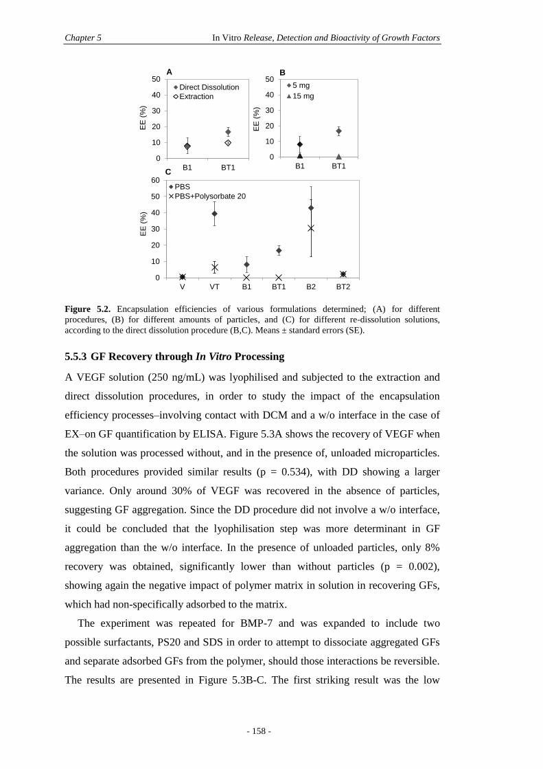
Chapter 5 In Vitro Release, Detection and Bioactivity of Growth Factors
- 158 -
Figure 5.2. Encapsulation efficiencies of various formulations determined; (A) for different
procedures, (B) for different amounts of particles, and (C) for different re-dissolution solutions,
according to the direct dissolution procedure (B,C). Means ± standard errors (SE).
5.5.3 GF Recovery through In Vitro Processing
A VEGF solution (250 ng/mL) was lyophilised and subjected to the extraction and
direct dissolution procedures, in order to study the impact of the encapsulation
efficiency processes–involving contact with DCM and a w/o interface in the case of
EX–on GF quantification by ELISA. Figure 5.3A shows the recovery of VEGF when
the solution was processed without, and in the presence of, unloaded microparticles.
Both procedures provided similar results (p = 0.534), with DD showing a larger
variance. Only around 30% of VEGF was recovered in the absence of particles,
suggesting GF aggregation. Since the DD procedure did not involve a w/o interface,
it could be concluded that the lyophilisation step was more determinant in GF
aggregation than the w/o interface. In the presence of unloaded particles, only 8%
recovery was obtained, significantly lower than without particles (p = 0.002),
showing again the negative impact of polymer matrix in solution in recovering GFs,
which had non-specifically adsorbed to the matrix.
The experiment was repeated for BMP-7 and was expanded to include two
possible surfactants, PS20 and SDS in order to attempt to dissociate aggregated GFs
and separate adsorbed GFs from the polymer, should those interactions be reversible.
The results are presented in Figure 5.3B-C. The first striking result was the low
0
10
20
30
40
50
B1 BT1
EE
(%
)
Direct Dissolution
Extraction
A B
C
0
10
20
30
40
50
B1 BT1
EE
(%
)
5 mg
15 mg
0
10
20
30
40
50
60
V VT B1 BT1 B2 BT2
EE
(%
)
PBS
PBS+Polysorbate 20
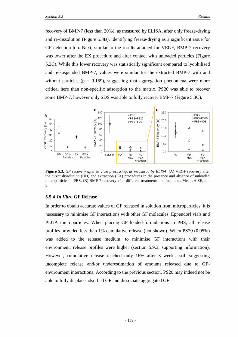
Section 5.5 Results
- 159 -
recovery of BMP-7 (less than 20%), as measured by ELISA, after only freeze-drying
and re-dissolution (Figure 5.3B), identifying freeze-drying as a significant issue for
GF detection too. Next, similar to the results attained for VEGF, BMP-7 recovery
was lower after the EX procedure and after contact with unloaded particles (Figure
5.3C). While this lower recovery was statistically significant compared to lyophilised
and re-suspended BMP-7, values were similar for the extracted BMP-7 with and
without particles (p = 0.159), suggesting that aggregation phenomena were more
critical here than non-specific adsorption to the matrix. PS20 was able to recover
some BMP-7, however only SDS was able to fully recover BMP-7 (Figure 5.3C).
Figure 5.3. GF recovery after in vitro processing, as measured by ELISA. (A) VEGF recovery after
the direct dissolution (DD) and extraction (EX) procedures in the presence and absence of unloaded
microparticles in PBS. (B) BMP-7 recovery after different treatments and mediums. Means ± SE, n =
3.
5.5.4 In Vitro GF Release
In order to obtain accurate values of GF released in solution from microparticles, it is
necessary to minimise GF interactions with other GF molecules, Eppendorf vials and
PLGA microparticles. When placing GF loaded-formulations in PBS, all release
profiles provided less than 1% cumulative release (not shown). When PS20 (0.05%)
was added to the release medium, to minimise GF interactions with their
environment, release profiles were higher (section 5.9.3, supporting information).
However, cumulative release reached only 16% after 3 weeks, still suggesting
incomplete release and/or underestimation of amounts released due to GF-
environment interactions. According to the previous section, PS20 may indeed not be
able to fully displace adsorbed GF and dissociate aggregated GF.
0
20
40
60
80
100
120
140
Solution FD FD+EX
FD+EX
+Particles
BM
P-7
Recovery
(%
)
PBS
PBS+PS20
PBS+SDS
0.0
5.0
10.0
15.0
20.0
25.0
FD FD+EX
FD+EX
+ParticlesB
MP
-7 R
eco
ve
ry (
%)
PBS
PBS+PS20
PBS+SDS
B C
0
10
20
30
40
50
60
DD DD +Particles
EX EX +Particles
VE
GF
Re
co
ve
ry (
%)
A
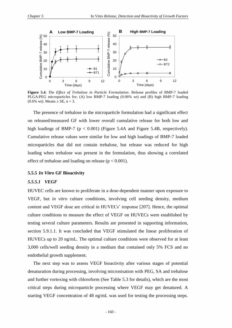
Chapter 5 In Vitro Release, Detection and Bioactivity of Growth Factors
- 160 -
Figure 5.4. The Effect of Trehalose in Particle Formulation. Release profiles of BMP-7 loaded
PLGA:PEG microparticles for; (A) low BMP-7 loading (0.06% wt) and (B) high BMP-7 loading
(0.6% wt). Means ± SE, n = 3.
The presence of trehalose in the microparticle formulation had a significant effect
on released/measured GF with lower overall cumulative release for both low and
high loadings of BMP-7 (p < 0.001) (Figure 5.4A and Figure 5.4B, respectively).
Cumulative release values were similar for low and high loadings of BMP-7 loaded
microparticles that did not contain trehalose, but release was reduced for high
loading when trehalose was present in the formulation, thus showing a correlated
effect of trehalose and loading on release (p < 0.001).
5.5.5 In Vitro GF Bioactivity
5.5.5.1 VEGF
HUVEC cells are known to proliferate in a dose-dependent manner upon exposure to
VEGF, but in vitro culture conditions, involving cell seeding density, medium
content and VEGF dose are critical in HUVECs’ response [207]. Hence, the optimal
culture conditions to measure the effect of VEGF on HUVECs were established by
testing several culture parameters. Results are presented in supporting information,
section 5.9.1.1. It was concluded that VEGF stimulated the linear proliferation of
HUVECs up to 20 ng/mL. The optimal culture conditions were observed for at least
3,000 cells/well seeding density in a medium that contained only 5% FCS and no
endothelial growth supplement.
The next step was to assess VEGF bioactivity after various stages of potential
denaturation during processing, involving micronisation with PEG, SA and trehalose
and further vortexing with chloroform (See Table 5.3 for details), which are the most
critical steps during microparticle processing where VEGF may get denatured. A
starting VEGF concentration of 48 ng/mL was used for testing the processing steps.
A B
0
10
20
30
40
50
0 3 6 9 12
Cum
ula
tive B
MP
-7 r
ele
ase (
%)
Time (days)
B1
BT1
0
10
20
30
40
50
0 3 6 9 12
Cu
mu
lative
BM
P-7
re
lea
se
(%
)
Time (days)
B2
BT2
Low BMP-7 Loading High BMP-7 Loading
Section 5.5 Results
- 161 -
After reconstitution in PBS, VEGF samples were dispensed on cells with a final
concentration in wells of 12 ng/mL. The quantification of VEGF concentration and
HUVEC proliferation are presented in Figure 5.5.
Table 5.3. Summary of treatments on HUVECs.
Name Description
NC1 Culture medium
NC2 Culture medium with 25% PBS + SA
NC3 Culture medium with 25% PBS + SA + PEG
NC4 Culture medium with 25% PBS + SA + PEG + trehalose
NC5 Culture medium with 25% PBS + SA + trehalose after contact with
chloroform
PC Fresh VEGF
T1 Freeze-dried VEGF
T2 Micronised VEGF with PEG and SA and trehalose
T3 Micronised VEGF with PEG, SA and trehalose, subjected to chloroform
First, upon micronisation and unlike BMP-7, it appeared that VEGF was fully
detectable according to ELISA analysis (Figure 5.5a, T1-T2). After contact with
chloroform (T3), however, only 69% VEGF was detected, suggesting GF
aggregation. Strikingly, when compared with the proliferation results, although
proliferation was slightly lower compared to the control (Figure 5.5b), there was no
statistical difference (p = 0.15) between PC and T3 groups. Importantly, the
proliferation result was identical for micronised VEGF before (T2) and after (T3)
contact with chloroform, with around 83% bioactivity (Figure 5.5C) in both cases.
Furthermore, it can be seen from the decreasing histograms in Figure 5.5B that each
subsequent processing step (freeze-drying, micronisation with additives) had an
increasingly negative impact on cell proliferation, although there were no statistical
differences with the control. This suggested that the processing steps themselves
were more critical for the bioactivity of VEGF than the contact of VEGF with
chloroform. Lastly, in order to confirm that it was not the presence of the various
additives (SA, PEG, trehalose) that impaired cell proliferation, HUVECs were
treated with negative controls that did not contain VEGF, but the various additives
(NC2 to NC5, Table 5.3) and results are shown in Figure 5.5D. No statistical
differences were observed between any groups.
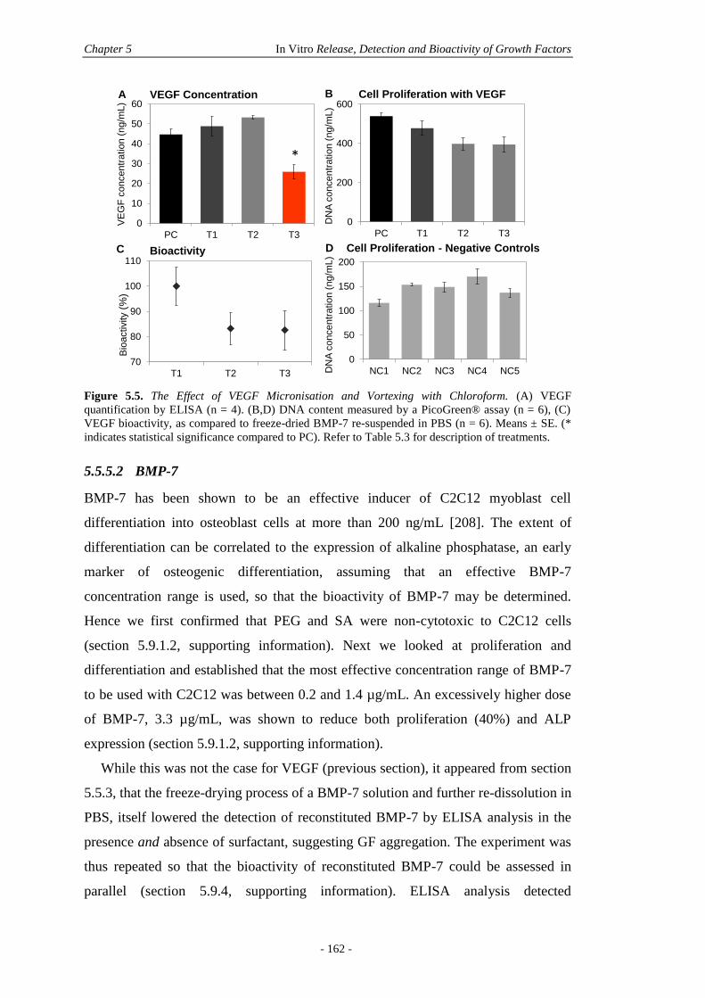
Chapter 5 In Vitro Release, Detection and Bioactivity of Growth Factors
- 162 -
Figure 5.5. The Effect of VEGF Micronisation and Vortexing with Chloroform. (A) VEGF
quantification by ELISA (n = 4). (B,D) DNA content measured by a PicoGreen® assay (n = 6), (C)
VEGF bioactivity, as compared to freeze-dried BMP-7 re-suspended in PBS (n = 6). Means ± SE. (*
indicates statistical significance compared to PC). Refer to Table 5.3 for description of treatments.
5.5.5.2 BMP-7
BMP-7 has been shown to be an effective inducer of C2C12 myoblast cell
differentiation into osteoblast cells at more than 200 ng/mL [208]. The extent of
differentiation can be correlated to the expression of alkaline phosphatase, an early
marker of osteogenic differentiation, assuming that an effective BMP-7
concentration range is used, so that the bioactivity of BMP-7 may be determined.
Hence we first confirmed that PEG and SA were non-cytotoxic to C2C12 cells
(section 5.9.1.2, supporting information). Next we looked at proliferation and
differentiation and established that the most effective concentration range of BMP-7
to be used with C2C12 was between 0.2 and 1.4 µg/mL. An excessively higher dose
of BMP-7, 3.3 µg/mL, was shown to reduce both proliferation (40%) and ALP
expression (section 5.9.1.2, supporting information).
While this was not the case for VEGF (previous section), it appeared from section
5.5.3, that the freeze-drying process of a BMP-7 solution and further re-dissolution in
PBS, itself lowered the detection of reconstituted BMP-7 by ELISA analysis in the
presence and absence of surfactant, suggesting GF aggregation. The experiment was
thus repeated so that the bioactivity of reconstituted BMP-7 could be assessed in
parallel (section 5.9.4, supporting information). ELISA analysis detected
0
10
20
30
40
50
60
PC T1 T2 T3
VE
GF
concentr
ation (
ng
/mL)
0
200
400
600
PC T1 T2 T3
DN
A c
oncentr
ation (
ng
/mL)
A BVEGF Concentration Cell Proliferation with VEGF
70
80
90
100
110
T1 T2 T3
Bio
activity
(%)
C DBioactivity Cell Proliferation - Negative Controls
0
50
100
150
200
NC1 NC2 NC3 NC4 NC5DN
A c
oncentr
ation (
ng/m
L)
*
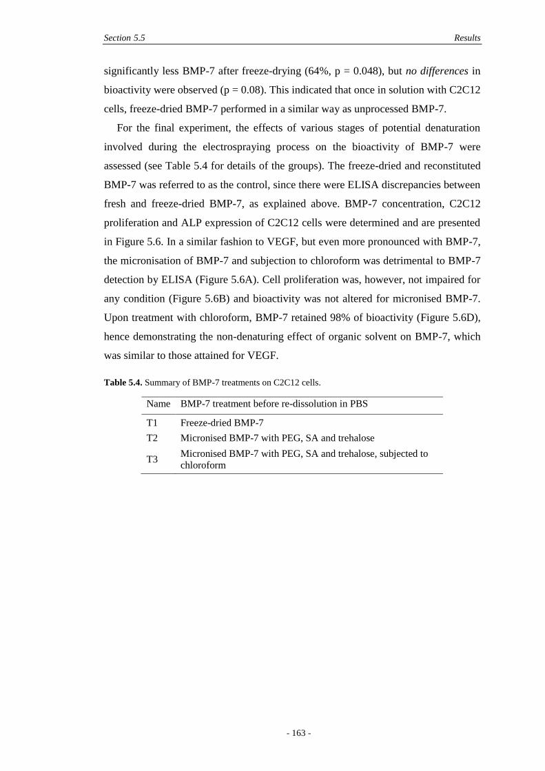
Section 5.5 Results
- 163 -
significantly less BMP-7 after freeze-drying (64%, p = 0.048), but no differences in
bioactivity were observed (p = 0.08). This indicated that once in solution with C2C12
cells, freeze-dried BMP-7 performed in a similar way as unprocessed BMP-7.
For the final experiment, the effects of various stages of potential denaturation
involved during the electrospraying process on the bioactivity of BMP-7 were
assessed (see Table 5.4 for details of the groups). The freeze-dried and reconstituted
BMP-7 was referred to as the control, since there were ELISA discrepancies between
fresh and freeze-dried BMP-7, as explained above. BMP-7 concentration, C2C12
proliferation and ALP expression of C2C12 cells were determined and are presented
in Figure 5.6. In a similar fashion to VEGF, but even more pronounced with BMP-7,
the micronisation of BMP-7 and subjection to chloroform was detrimental to BMP-7
detection by ELISA (Figure 5.6A). Cell proliferation was, however, not impaired for
any condition (Figure 5.6B) and bioactivity was not altered for micronised BMP-7.
Upon treatment with chloroform, BMP-7 retained 98% of bioactivity (Figure 5.6D),
hence demonstrating the non-denaturing effect of organic solvent on BMP-7, which
was similar to those attained for VEGF.
Table 5.4. Summary of BMP-7 treatments on C2C12 cells.
Name BMP-7 treatment before re-dissolution in PBS
T1 Freeze-dried BMP-7
T2 Micronised BMP-7 with PEG, SA and trehalose
T3 Micronised BMP-7 with PEG, SA and trehalose, subjected to
chloroform
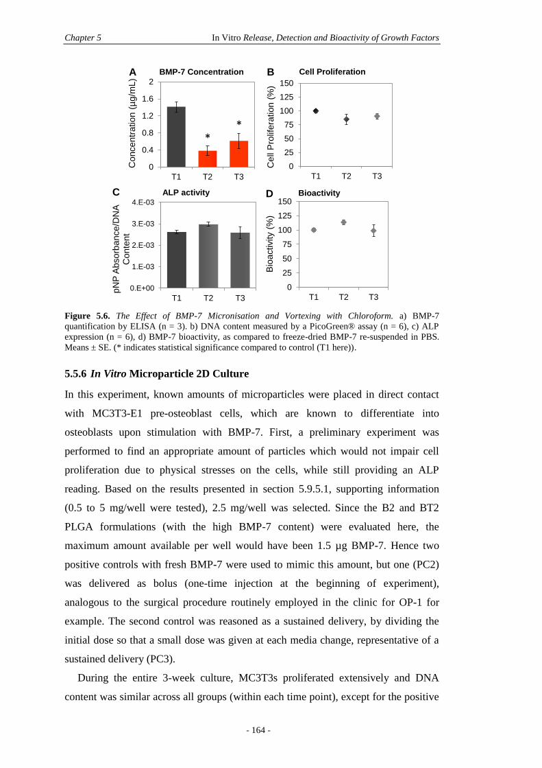
Chapter 5 In Vitro Release, Detection and Bioactivity of Growth Factors
- 164 -
Figure 5.6. The Effect of BMP-7 Micronisation and Vortexing with Chloroform. a) BMP-7
quantification by ELISA (n = 3). b) DNA content measured by a PicoGreen® assay (n = 6), c) ALP
expression (n = 6), d) BMP-7 bioactivity, as compared to freeze-dried BMP-7 re-suspended in PBS.
Means ± SE. (* indicates statistical significance compared to control (T1 here)).
5.5.6 In Vitro Microparticle 2D Culture
In this experiment, known amounts of microparticles were placed in direct contact
with MC3T3-E1 pre-osteoblast cells, which are known to differentiate into
osteoblasts upon stimulation with BMP-7. First, a preliminary experiment was
performed to find an appropriate amount of particles which would not impair cell
proliferation due to physical stresses on the cells, while still providing an ALP
reading. Based on the results presented in section 5.9.5.1, supporting information
(0.5 to 5 mg/well were tested), 2.5 mg/well was selected. Since the B2 and BT2
PLGA formulations (with the high BMP-7 content) were evaluated here, the
maximum amount available per well would have been 1.5 µg BMP-7. Hence two
positive controls with fresh BMP-7 were used to mimic this amount, but one (PC2)
was delivered as bolus (one-time injection at the beginning of experiment),
analogous to the surgical procedure routinely employed in the clinic for OP-1 for
example. The second control was reasoned as a sustained delivery, by dividing the
initial dose so that a small dose was given at each media change, representative of a
sustained delivery (PC3).
During the entire 3-week culture, MC3T3s proliferated extensively and DNA
content was similar across all groups (within each time point), except for the positive
0
0.4
0.8
1.2
1.6
2
T1 T2 T3
Co
nce
ntr
atio
n (
µg/m
L)
BMP-7 Concentration
0
25
50
75
100
125
150
T1 T2 T3
Cell
Pro
lifera
tion (
%)
Cell Proliferation
0.E+00
1.E-03
2.E-03
3.E-03
4.E-03
T1 T2 T3
pN
P A
bsorb
ance/D
NA
C
on
tent
ALP activity
0
25
50
75
100
125
150
T1 T2 T3
Bio
activity (
%)
Bioactivity
BA
C D
**
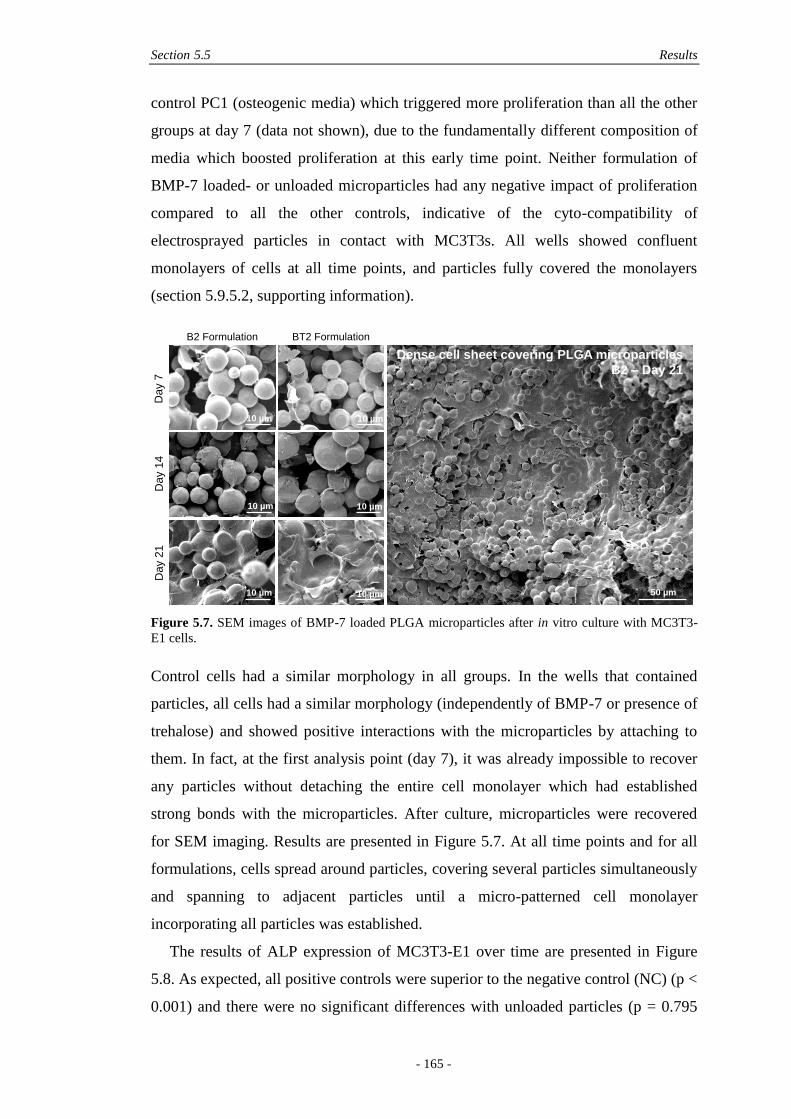
Section 5.5 Results
- 165 -
control PC1 (osteogenic media) which triggered more proliferation than all the other
groups at day 7 (data not shown), due to the fundamentally different composition of
media which boosted proliferation at this early time point. Neither formulation of
BMP-7 loaded- or unloaded microparticles had any negative impact of proliferation
compared to all the other controls, indicative of the cyto-compatibility of
electrosprayed particles in contact with MC3T3s. All wells showed confluent
monolayers of cells at all time points, and particles fully covered the monolayers
(section 5.9.5.2, supporting information).
Figure 5.7. SEM images of BMP-7 loaded PLGA microparticles after in vitro culture with MC3T3-
E1 cells.
Control cells had a similar morphology in all groups. In the wells that contained
particles, all cells had a similar morphology (independently of BMP-7 or presence of
trehalose) and showed positive interactions with the microparticles by attaching to
them. In fact, at the first analysis point (day 7), it was already impossible to recover
any particles without detaching the entire cell monolayer which had established
strong bonds with the microparticles. After culture, microparticles were recovered
for SEM imaging. Results are presented in Figure 5.7. At all time points and for all
formulations, cells spread around particles, covering several particles simultaneously
and spanning to adjacent particles until a micro-patterned cell monolayer
incorporating all particles was established.
The results of ALP expression of MC3T3-E1 over time are presented in Figure
5.8. As expected, all positive controls were superior to the negative control (NC) (p <
0.001) and there were no significant differences with unloaded particles (p = 0.795
Dense cell sheet covering PLGA microparticles
B2 – Day 21
B2 Formulation BT2 Formulation
Da
y 7
Da
y 1
4D
ay 2
1
10 µm 10 µm
10 µm 10 µm
10 µm 10 µm 50 µm
Chapter 5 In Vitro Release, Detection and Bioactivity of Growth Factors
- 166 -
and 0.877 for Blank (no trehalose in formulation) and BlankT (trehalose in
formulation), respectively – See Table 1 for details). Interestingly, while the bolus
delivery (PC2) consisted of only one BMP-7 injection at the beginning of the
experiment, ALP expression was still observed after 3 weeks, although decreasing
over time. Except at day 14, where the sustained delivery (PC3) was higher than the
bolus delivery (p = 0.04), there were no differences at day 7 and day 21, implying
here that there were no long-term benefits in the sustained delivery compared to the
bolus delivery although the effect at 14 days was significant and so proved that a
constant stimulus with fresh BMP up to 2 weeks provided more differentiated cells
than with the bolus delivery.
As can be seen from Figure 5.8, both formulations of BMP-7-loaded particles
(B2/B2T, +/- trehalose) had enhanced readings compared to the negative controls
(NC, C3, C4) at all time points, proving that both formulations could still have a
positive effect on the differentiation of MC3T3-E1 cells up to three weeks, while the
release data (Figure 5.4B) suggested no more release of BMP-7 was detected after
three days. Compared to the sustained delivery control (PC3), readings were however
lower at all time points, suggesting that the dose delivered by microparticles was
inferior to its fresh counterpart. Importantly, contrary to what was suggested by the
release profiles in Figure 5.4, there were no statistical differences between the
trehalose free BMP-7 formulation (B2) and the trehalose BMP-7 formulation (BT2),
which performed in a similar way at all time points.
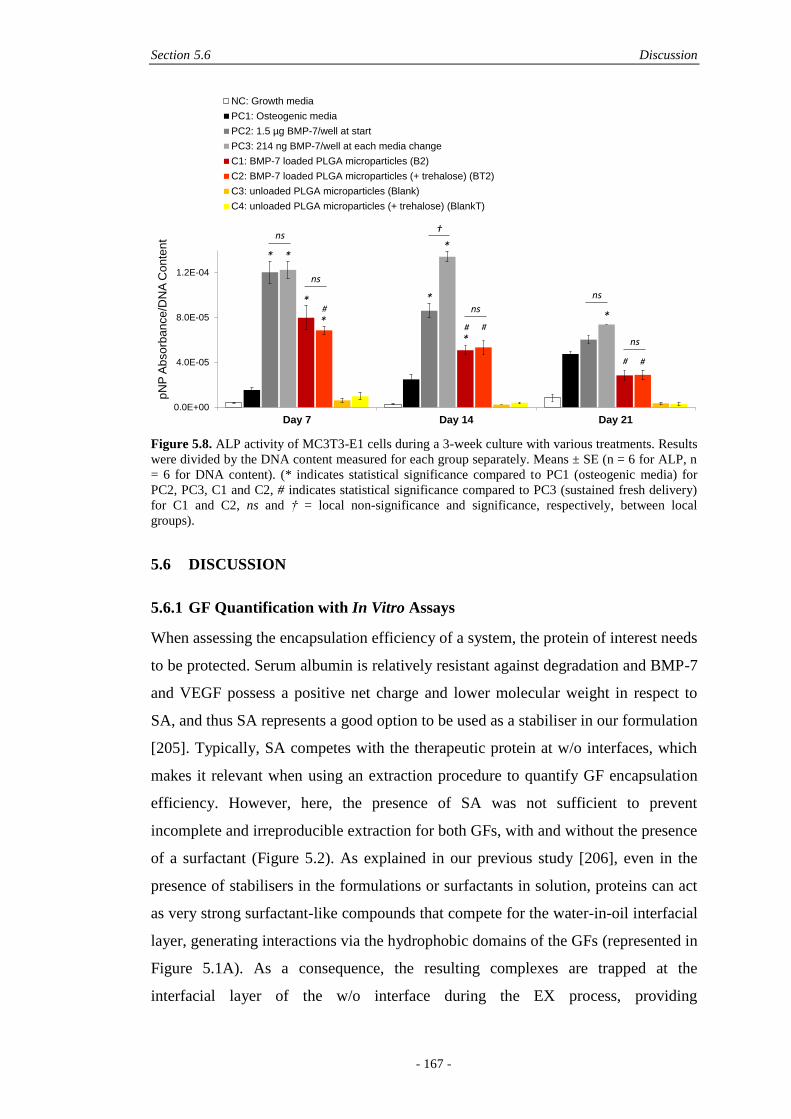
Section 5.6 Discussion
- 167 -
Figure 5.8. ALP activity of MC3T3-E1 cells during a 3-week culture with various treatments. Results
were divided by the DNA content measured for each group separately. Means ± SE (n = 6 for ALP, n
= 6 for DNA content). (* indicates statistical significance compared to PC1 (osteogenic media) for
PC2, PC3, C1 and C2, # indicates statistical significance compared to PC3 (sustained fresh delivery)
for C1 and C2, ns and † = local non-significance and significance, respectively, between local
groups).
5.6 DISCUSSION
5.6.1 GF Quantification with In Vitro Assays
When assessing the encapsulation efficiency of a system, the protein of interest needs
to be protected. Serum albumin is relatively resistant against degradation and BMP-7
and VEGF possess a positive net charge and lower molecular weight in respect to
SA, and thus SA represents a good option to be used as a stabiliser in our formulation
[205]. Typically, SA competes with the therapeutic protein at w/o interfaces, which
makes it relevant when using an extraction procedure to quantify GF encapsulation
efficiency. However, here, the presence of SA was not sufficient to prevent
incomplete and irreproducible extraction for both GFs, with and without the presence
of a surfactant (Figure 5.2). As explained in our previous study [206], even in the
presence of stabilisers in the formulations or surfactants in solution, proteins can act
as very strong surfactant-like compounds that compete for the water-in-oil interfacial
layer, generating interactions via the hydrophobic domains of the GFs (represented in
Figure 5.1A). As a consequence, the resulting complexes are trapped at the
interfacial layer of the w/o interface during the EX process, providing
0.0E+00
4.0E-05
8.0E-05
1.2E-04
Day 7 Day 14 Day 21
pN
PA
bsorb
ance/D
NA
Co
nte
nt
NC: Growth media
PC1: Osteogenic media
PC2: 1.5 µg BMP-7/well at start
PC3: 214 ng BMP-7/well at each media change
C1: BMP-7 loaded PLGA microparticles (B2)
C2: BMP-7 loaded PLGA microparticles (+ trehalose) (BT2)
C3: unloaded PLGA microparticles (Blank)
C4: unloaded PLGA microparticles (+ trehalose) (BlankT)
ns
ns
ns
ns
ns
†
* *
*
*
*
*
*
*#
# #
# #
Chapter 5 In Vitro Release, Detection and Bioactivity of Growth Factors
- 168 -
underestimated EE values (Figure 5.1B). This was further proven in section 5.5.3,
when ‘non-encapsulated’ VEGF and BMP-7 were submitted to the extraction
process, showing first GF aggregation, and then non-specific adsorption to polymer
once unloaded particles were added to both GF solutions (Figure 5.3).
Importantly, BMP-7 showed extensive aggregation during the freeze-drying step
(only 20% recovery), even before any extraction treatment (Figure 5.3), as measured
by ELISA. A similar result was observed by Lochmann et al. where one single
freeze/thaw cycle caused a loss of about one third in ELISA detection of BMP-2,
clearly suggesting that the freezing step was the issue [199]. Remarkably, when
testing here freeze-dried BMP-7 on cells, no bioactivity differences were observed in
vitro in contact with C2C12 cells, compared to control BMP-7 (Figure 5.6). Hence,
while the ELISA assay could have suggested covalent GF aggregation upon freeze-
drying, the bioactivity assay confirmed that the interactions were non-covalent in
nature, since BMP-7 was not denatured and performed equally as well as before
freeze-drying. This result really emphasises the limitations of the ELISA assay,
especially for assessing the ‘bioactivity’ of a GF. For instance Wang et al. showed
that after lyophilisation, they had lost 75% of the BMP-2 detectable by ELISA and
thus increased their in vivo dose for compensation, stating that 75% of the
‘bioactivity’ was lost [209]. This approach is erroneous considering that the ELISA
assay is proven here to be an insufficient and misleading means of ‘bioactivity’
detection, and that cell assays remain a superior method for assessing the bioactivity
of a processed GF.
5.6.2 The Use of Surfactants in In Vitro Assays
Surfactants are amphiphilic molecules commonly used to lower the surface tension
between dissimilar phases. In the presence of proteins, they act by effectively raising
the energy barrier for intermolecular interactions between proteins by surrounding
them with their hydrophilic ends. The alignment of surfactant molecules around the
proteins and the thickness of the surfactant layer are determinant in the surfactant’s
performance [175]. Here, two types of surfactants were investigated in GF recovery,
EE and release assays; a non-ionic surfactant, polysorbate 20 (PS20), and a less
commonly used anionic surfactant, sodium dodecyl sulphate (SDS).
When a BMP-7 solution was subjected to the extraction procedure with and
without the presence of unloaded particles, both surfactants were beneficial in

Section 5.6 Discussion
- 169 -
dissociating non-covalent BMP-7 aggregates and displacing adsorbed BMP-7 from
the polymer matrix (Figure 5.3). SDS was more effective than PS20 for BMP-7, with
fully recovered BMP-7, which is attributed to the ionic and steric differences of the
surfactant’s heads. Importantly, these results proved that the extraction process,
involving GF dispersion in organic solvent and a w/o interface generated only
reversible conformational changes. However, when using PS20 for extracting both
BMP-7 and VEGF from loaded microparticles, lower encapsulation efficiencies than
with PBS only were measured by ELISA (Figure 5.2), when the direct dissolution
(DD) procedure was used. This is explained by the absence of w/o interface in the
DD procedure. In the extraction case, surfactants compete with the GFs for the
interface, hence efficiently shielding the proteins from the interface. In the DD
procedure, upon evaporation of the organic solvent, the dried polymer becomes the
preferential site for GF interactions, hence favouring aggregation and adsorption.
Once these phenomena have happened, the presence of surfactant in the re-
dissolution medium actually favours those interactions, hence inhibiting dissociation
of aggregated and adsorbed BMP-7 [205]. In contrast, when PS20 was added to the
release medium, up to 16% cumulative release was observed for BT1 particles,
compared to less than 1% for PBS only. Thus, contrary to the EE results, PS20
clearly promoted release. This inferred that encapsulated BMP-7 within the
microparticles was less aggregated and less adsorbed to the polymer matrix than it
was upon the DD process, leading to a beneficial effect of PS20 in release media but
not in the EE procedure. Incomplete release and low amounts recovered still
suggested that the protection by PS20 was poor. An ionic surfactant may thus be
more relevant in the context of protein recovery [204, 210].
5.6.3 The Use of Stabilisers in Microparticle Formulations
The use of sugars as stabilising agents for encapsulation of therapeutic molecules
into polymer particles has been incredibly well covered over the last twenty years
[34, 125, 205, 211]. Like other stabilisers, sugars protect proteins by preferential
interactions [201, 204, 205]. However, it is clear from the literature that there is not
always a beneficial effect in using any sugar with any protein, and sugars rather work
on a protein-to-protein basis, possibly drawing ambivalent pictures for different
proteins. Bilati et al. have summarised some recent studies, involving, amongst
others, lysozyme, NGF, IGF-I, with mono- and polysaccharides [125]. They
Chapter 5 In Vitro Release, Detection and Bioactivity of Growth Factors
- 170 -
concluded that trehalose was statistically more effective than other sugars, as
opposed to mannitol, which was largely inefficient. While many studies report
protein stability data, less information is found upon the effect of trehalose on the
actual encapsulation efficiency and release of proteins from polymeric particles. As
mentioned by Wu et al., the influence on release characteristics needs to be
addressed since some stabilisers are compromised with burst release or aggregation
upon release [171].
Here, when 1% wt trehalose was present in the final particle formulations that
contained high amounts of BMP-7, reduced encapsulation efficiency (Figure 5.2) and
burst release followed by incomplete release were observed (Figure 5.4). However,
there were no statistical differences between the trehalose-loaded and trehalose-free
formulations when cultured with MC3T3-E1 cells, which presented similar ALP
values over time and triggered differentiation up to three weeks (Figure 5.8),
contrary to both what the encapsulation efficiency and release assay in solution (no
cells) had predicted. Clearly, the presence of trehalose had no negative impact on the
actual encapsulation and delivery of BMP-7 and its presence in the microparticle
formulation was only detrimental to the detection of BMP-7 in solution. Hence,
trehalose is shown here to promote GF non-covalent aggregation during
lyophilisation, which impaired accurate quantification, but not effectiveness of the
delivery system. This is an important result considering that many studies only
address additives in solution and do not compare results with actual cell assays,
which, as demonstrated here, may show different results. Here, because there was no
actual benefit to use trehalose in the formulation, but rather it led to inaccuracies in
quantification, trehalose may not necessarily need to be used within BMP-7 loaded
electrosprayed PLGA microparticles, since PEG only may have been sufficient to
ensure GF bioactivity. Interestingly, 10% wt PEG in the microparticle formulation
may not have been sufficient to prevent GF aggregation for ELISA readings. In
general, PLGA/PEG blends in traditional microparticles are efficient in reducing
aggregation [176]. However, Jiang and Schwendeman showed that less than 20% wt
PEG content in PLA/PEG microspheres resulted in incomplete and insoluble non-
covalent SA aggregates [180]. A similar issue may have happened here with the
PLGA/PEG formulations. However, increasing the amount of PEG in the
electrospraying solution leads to less reproducible morphologies due to
electrospraying jet instabilities [206].
Section 5.6 Discussion
- 171 -
As stated by Walle et al., while the use of trehalose and PEG is very popular, a
clear need for these additives has not yet emerged and case-by-case basis studies are
required [211]. In electrospraying, we showed that PEG was efficiently used to
homogeneously encapsulate dry proteins and gave tailored protein release profiles,
but PEG was not sufficient to address in vitro quantification assays where non-
covalent aggregation hindered accurate measurements by ELISA.
5.6.4 Bioactivity of GF through In Vitro Processing
In the literature, the bioactivity of proteins (SA) and growth factors (IGF-1, PDGF,
VEGF, BMP-7, TGF-β3) immediately released from electrosprayed particles and
assessed with cell proliferation assays was high (80-90%) [29, 30, 71]. Interestingly,
over time, the bioactivity of released VEGF and PDGF decreased (less than 21%
after 21 days), which the authors attributed to the assay conditions which denatured
the GFs, prone to oxidation and pH-dependent deamidation [30]. This result, in
particular, underlines the unsuitability of PBS assays, where cells are not present, for
assessing released GFs.
Here, when encapsulating GFs into electrosprayed particles, there are two steps
which may potentially denature GFs; first the micronisation with additives, then the
mixing with organic solvent prior to electrospraying. It is thus important to assess the
bioactivity of GFs after those two steps, rather than after release in buffer which in
itself involves denaturing factors. Hence, those conditions were assessed separately
and in combination, for BMP-7 and VEGF. The micronisation step and contact with
solvent were proven non-harmful to BMP-7 bioactivity (98% bioactive), although the
ELISA quantification measured a lower reading for those conditions (only 43% of
the control), (Figure 5.5). This confirmed that the micronisation and contact with
solvent generated a large degree of BMP-7 aggregation, but which was non-covalent
since bioactivity was not impaired. With VEGF, the ELISA analysis detected no
aggregation during the micronisation step, but like BMP-7, the reading for VEGF
was lower after contact with organic solvent (58% of the control), although, as with
the BMP-7, no significant differences in bioactivity were noted (83% bioactive),
(Figure 5.6). These results have thus shown that for both growth factors studied here,
a large degree of aggregation occurred after vortexing with organic solvent, which
biased quantification with an ELISA assay. However aggregated GFs had no
significant impact on both GFs’ bioactivities, and performed equally to controls.

Chapter 5 In Vitro Release, Detection and Bioactivity of Growth Factors
- 172 -
5.6.5 GF Delivery in an In Vitro 2D Culture
The previous sections validated the pre-electrospraying processing steps as safe for
maintaining GF bioactivity but really serve to emphasise the difficulties of GF
quantification. Next, the GF bioactivity post-processing was assessed in combination
with a direct contact assay with cells. Cells actively consume growth factors, either
released in the medium or by direct contact with the microparticles. An in vitro
context with cells has some similarities with the in vivo context, and is fundamentally
better than simple PBS assays where no cells are present to take up released growth
factors, which may fatally get adsorbed or aggregated in solution before analysis.
Therefore it was paramount for assessing the efficiency of the electrosprayed
microparticles to place the microparticles directly in contact with cells in a 2D in
vitro culture, which was done here with BMP-7 loaded formulations in contact with
MC3T3-E1 cells.
Microscopy analysis revealed the positive interactions of particles with cells,
which firmly bonded together to form particle-integrated monolayers (Figure 5.7),
and did not impair cell proliferation. The size of electrosprayed particles was within
the order of size of MC3T3-E1 cells, thus was suitable for cellular stimulation by
topographical cues [212]. Positive interactions were expected considering that
unloaded and protein-loaded electrosprayed microparticles on the 5 to 10 µm size
range had shown positive effects on several cell types including fibroblasts [83] and
pre-osteoblasts [182] but such positive effects were shown here for the first time with
growth-factor loaded electrosprayed particles.
When BMP-7 was freshly delivered in a sustained fashion (PC3), ALP readings
were higher than the readings from electrosprayed particles at all time points (Figure
5.8). This is explained by the particles not being degraded after 21 days as evidenced
by SEM analysis (Figure 5.7) and we hypothesise that more BMP-7 may be released
afterwards. This can only be addressed by a complementary assay done over a longer
time frame, such as alizarin red staining, which highlights mineralised bone-like
tissue, since ALP is only an early marker of osteogenic differentiation. Here, the
dose selection for PC3 was quite high; it was the maximum possible dose
encapsulated in particles, i.e. 1.5 µg, which was evenly dispensed during media
changes, i.e. 214 ng per change. This strategy inferred that the full dose was
dispensed after 3 weeks which could only be rigorously compared to the
microparticles if they had fully degraded, which was not the case. Slow degradation
Section 5.7 Conclusions
- 173 -
was due to the polymer used here, PLGA 85:15, which contained a high lactide
fraction. The 10% PEG in the formulation did not increase degradation significantly
over the 3-week study. To conclude, it is more relevant to compare the ALP readings
from particles with the negative controls (NC), which showed that released BMP-7
was still active and triggering cell differentiation after 3 weeks.
Finally, an interesting result from this study is the similar effect of bolus (PC2)
and sustained delivery (PC3) of fresh BMP-7, which, except at day 14, did not show
statistical differences during the 3-week period (Figure 5.8), implying here that there
were no long-term benefits in the sustained delivery compared to the bolus delivery
in terms of stimulating osteogenic differentiation of MC3T3-E1 cells. However, the
effect of sustained delivery at 14 days was highly significant, proving that a constant
stimulus with fresh BMP-7 up to 2 weeks provided differentiated cells sooner than
with the bolus delivery. This phenomenon is explained by BMP-7 molecules getting
rapidly degraded with the bolus delivery, due to the short half-life of BMPs delivered
in vitro in solution [30]. Ideally, by using release systems such as the electrosprayed
particles presented here, that can lower the daily dose while ensuring bioactivity of
released GFs, we will avoid unnecessary overcrowding within the defect site, and
dispense lower doses of growth factors over longer timeframes than exhibited by
bolus deliveries. This may in turn lead to safer and more efficacious GF treatments,
which are also less expensive owing to containment of lower doses of GF.
5.7 CONCLUSIONS
In this study, bone growth factors; VEGF and BMP-7, were encapsulated into PLGA
85:15 microparticles by electrospraying and assessed by PBS-based assays and
cellular assays. Fundamental differences were observed, where quantification
procedures that did not involve cells led to GF interactions, which impaired accurate
ELISA detection and biased the actual results. When processed GFs were tested with
cells, GF interactions were indicated to be non-covalent since GF bioactivity was
verified at all steps of microparticle processing (involving micronisation and contact
with organic solvent), although ELISA recovery was lower for both VEGF and
BMP-7 after contact with chloroform. Similarly, the presence of trehalose in the
microparticle formulations did not affect GF bioactivity, although it negatively
impacted GF detection via ELISA in encapsulation and release assays in PBS, hence
Chapter 5 In Vitro Release, Detection and Bioactivity of Growth Factors
- 174 -
inferring that PEG was sufficient to protect GF bioactivity in electrosprayed
particles. The positive effect of BMP-7 loaded electrosprayed particles in
differentiating pre-osteoblasts up to 3 weeks provided further proof of the
discrepancies between release assays in PBS and measured by ELISA, and the actual
effectiveness seen with direct contact with cells. Taken together, these important
results highlight the importance of looking at appropriate analysis techniques for GF
delivery, which is a complex undertaking with multiple interactions. A major change
in the assessment of microparticle systems containing intricate molecules such as
growth factors may be needed, hopefully paving the way to further development and
use of cell-based assays to accurately evaluate protein-carrier formulations.
5.8 ACKNOWLEDGEMENTS
The authors wish to thank Prof. George Muscat from the University of Queensland
for providing C2C12 cells and Dr. Mary Wang for help with handling. Thanks to the
Australian Research Council (ARC), LP130100945, for financial support. N.B. also
acknowledges the financial support from QUT in the form of an Australian
Postgraduate Award scholarship, and top-up from the Deputy Vice Chancellor.
M.A.W. acknowledges support from the ARC LP100200084.
5.9 SUPPORTING INFORMATION
5.9.1 Culture Conditions for GF Bioactivity Assessment
5.9.1.1 VEGF
The effect of endothelial growth supplement (ECGS) and foetal calf serum (FCS) on
the proliferation of human umbilical vein endothelial cells (HUVECs) was assessed,
for a starting seeding density of 3,000 cells/well in a 96-well plate and after 3 days of
incubation. Results are presented in Figure S5.9a.

Section 5.9 Supporting Information
- 175 -
Figure S5.9. The Effect of FCS amount, SA and ECGS on Proliferation of HUVECs. Means ± SE, n =
5.
There was a significant impact of ECGS on HUVECs (p < 0.001), where the addition
of the supplement increased cell proliferation in a four-fold manner, for any amount
of FCS (5 or 10%). Without ECGS, the addition of 10% FCS instead of 5% had a
slight, but significant (p = 0.021), negative effect on cells. It could be concluded that
the ECGS supplement was the most critical factor to proliferation of HUVECs cells.
Since serum albumin (SA) was used as an excipient in electrosprayed microparticles,
its effect on cell proliferation was also verified (Figure S5.9b). It was observed that
the presence of SA slightly decreased cell proliferation, but not in significantly
manner (p = 0.4).
Figure S5.10 shows the proliferation results of HUVECs for increasing doses of
fresh VEGF. When ECGS was present in the medium, the addition of extra VEGF
led to a decrease in cell proliferation (Figure S5.10), representative of an excessive
amount of GFs in solution. In the absence of ECGS, the exogenous VEGF delivery
significantly increased cell numbers at all concentrations; 4, 8 and 20 ng/mL, in a
linear dose-dependent manner (Figure S5.10A).
Figure S5.10. The Effect of VEGF Dose on Proliferation of HUVECs. Means ± SE, n = 5.
0
200
400
600
800
1000
(-)ECGS (+)ECGS
DN
A c
on
ce
ntr
atio
n (
ng
/mL
)
5% FCS
10% FCS
0
200
400
600
800
1000
(-)ECGS (+)ECGS
DN
A c
oncentr
ation (
ng/m
L)
5% FCS
5% FCS with SA
A B
A B
100
200
300
400
500
0 4 8 12 16 20 24
DN
A c
oncentr
ation (
ng/m
L)
VEGF Concentration (ng/mL)
(-) ECGS
200
300
400
500
600
700
0 4 8 12 16 20 24
DN
A c
once
ntr
ation (
ng/m
L)
VEGF Concentration (ng/mL)
(+) ECGS
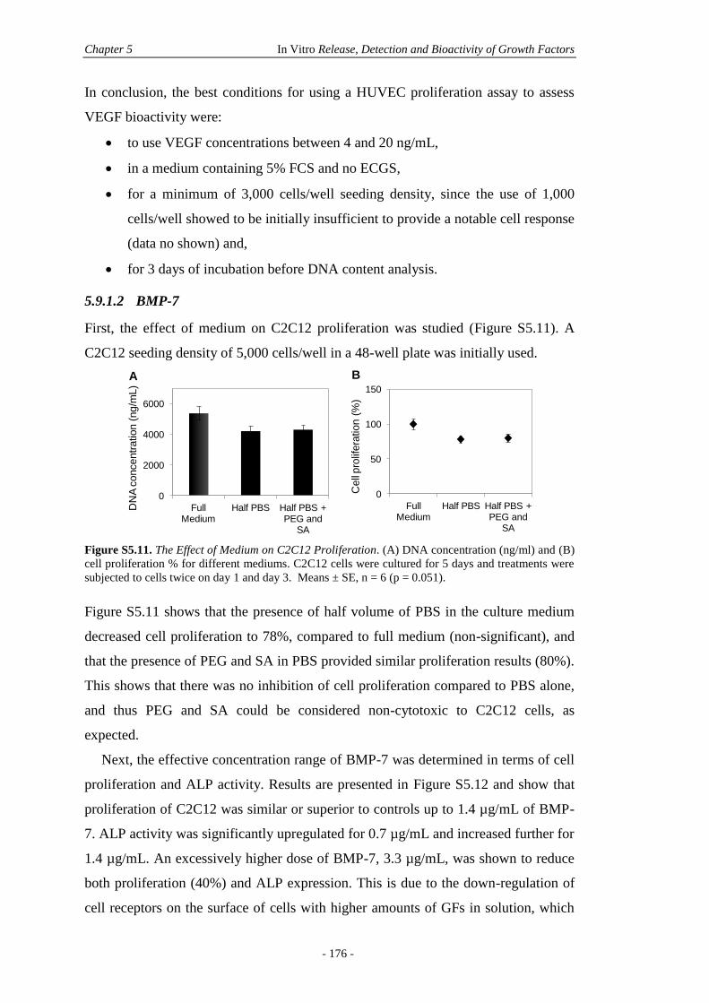
Chapter 5 In Vitro Release, Detection and Bioactivity of Growth Factors
- 176 -
In conclusion, the best conditions for using a HUVEC proliferation assay to assess
VEGF bioactivity were:
to use VEGF concentrations between 4 and 20 ng/mL,
in a medium containing 5% FCS and no ECGS,
for a minimum of 3,000 cells/well seeding density, since the use of 1,000
cells/well showed to be initially insufficient to provide a notable cell response
(data no shown) and,
for 3 days of incubation before DNA content analysis.
5.9.1.2 BMP-7
First, the effect of medium on C2C12 proliferation was studied (Figure S5.11). A
C2C12 seeding density of 5,000 cells/well in a 48-well plate was initially used.
Figure S5.11. The Effect of Medium on C2C12 Proliferation. (A) DNA concentration (ng/ml) and (B)
cell proliferation % for different mediums. C2C12 cells were cultured for 5 days and treatments were
subjected to cells twice on day 1 and day 3. Means ± SE, n = 6 (p = 0.051).
Figure S5.11 shows that the presence of half volume of PBS in the culture medium
decreased cell proliferation to 78%, compared to full medium (non-significant), and
that the presence of PEG and SA in PBS provided similar proliferation results (80%).
This shows that there was no inhibition of cell proliferation compared to PBS alone,
and thus PEG and SA could be considered non-cytotoxic to C2C12 cells, as
expected.
Next, the effective concentration range of BMP-7 was determined in terms of cell
proliferation and ALP activity. Results are presented in Figure S5.12 and show that
proliferation of C2C12 was similar or superior to controls up to 1.4 µg/mL of BMP-
7. ALP activity was significantly upregulated for 0.7 µg/mL and increased further for
1.4 µg/mL. An excessively higher dose of BMP-7, 3.3 µg/mL, was shown to reduce
both proliferation (40%) and ALP expression. This is due to the down-regulation of
cell receptors on the surface of cells with higher amounts of GFs in solution, which
0
2000
4000
6000
Full Medium
Half PBS Half PBS + PEG and
SA
DN
A c
oncentr
ation (
ng/m
L)
0
50
100
150
Full Medium
Half PBS Half PBS + PEG and
SA
Cell
pro
lifera
tion (
%)
A B
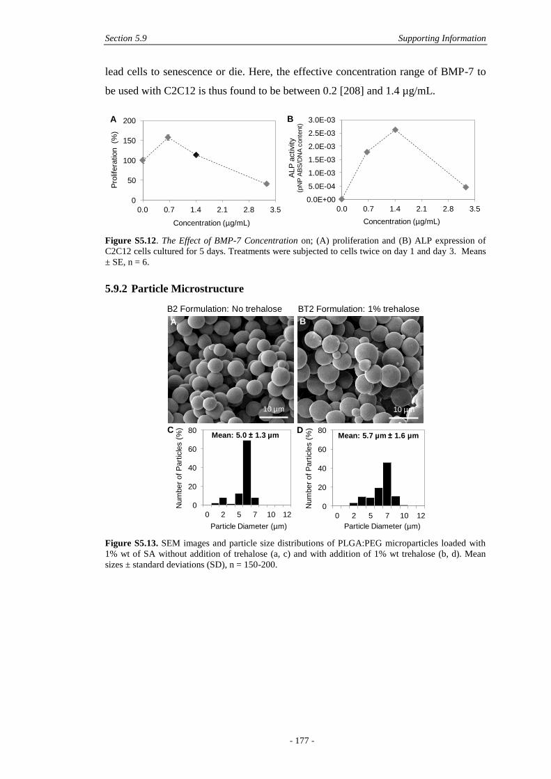
Section 5.9 Supporting Information
- 177 -
lead cells to senescence or die. Here, the effective concentration range of BMP-7 to
be used with C2C12 is thus found to be between 0.2 [208] and 1.4 µg/mL.
Figure S5.12. The Effect of BMP-7 Concentration on; (A) proliferation and (B) ALP expression of
C2C12 cells cultured for 5 days. Treatments were subjected to cells twice on day 1 and day 3. Means
± SE, n = 6.
5.9.2 Particle Microstructure
Figure S5.13. SEM images and particle size distributions of PLGA:PEG microparticles loaded with
1% wt of SA without addition of trehalose (a, c) and with addition of 1% wt trehalose (b, d). Mean
sizes ± standard deviations (SD), n = 150-200.
0
50
100
150
200
0.0 0.7 1.4 2.1 2.8 3.5
Pro
lifera
tion (%
)
Concentration (µg/mL)
0.0E+00
5.0E-04
1.0E-03
1.5E-03
2.0E-03
2.5E-03
3.0E-03
0.0 0.7 1.4 2.1 2.8 3.5
ALP
activity
(pN
PA
BS
/DN
A c
onte
nt)
Concentration (µg/mL)
A B
B2 Formulation: No trehalose BT2 Formulation: 1% trehalose
0
20
40
60
80
0 2 5 7 10 12
Num
ber
of P
art
icle
s (
%)
Particle Diameter (µm)
0
20
40
60
80
0 2 5 7 10 12
Num
ber
of P
art
icle
s (
%)
Particle Diameter (µm)
A B
C DMean: 5.0 1.3 µm Mean: 5.7 µm 1.6 µm
10 µm 10 µm
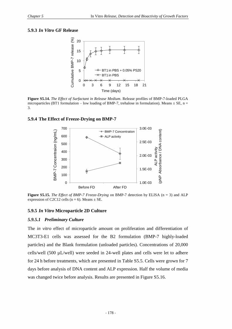
Chapter 5 In Vitro Release, Detection and Bioactivity of Growth Factors
- 178 -
5.9.3 In Vitro GF Release
Figure S5.14. The Effect of Surfactant in Release Medium. Release profiles of BMP-7-loaded PLGA
microparticles (BT1 formulation – low loading of BMP-7, trehalose in formulation). Means ± SE, n =
3.
5.9.4 The Effect of Freeze-Drying on BMP-7
Figure S5.15. The Effect of BMP-7 Freeze-Drying on BMP-7 detection by ELISA (n = 3) and ALP
expression of C2C12 cells (n = 6). Means ± SE.
5.9.5 In Vitro Microparticle 2D Culture
5.9.5.1 Preliminary Culture
The in vitro effect of microparticle amount on proliferation and differentiation of
MC3T3-E1 cells was assessed for the B2 formulation (BMP-7 highly-loaded
particles) and the Blank formulation (unloaded particles). Concentrations of 20,000
cells/well (500 µL/well) were seeded in 24-well plates and cells were let to adhere
for 24 h before treatments, which are presented in Table S5.5. Cells were grown for 7
days before analysis of DNA content and ALP expression. Half the volume of media
was changed twice before analysis. Results are presented in Figure S5.16.
0
5
10
15
20
0 3 6 9 12 15 18 21Cu
mu
lative
BM
P-7
re
lea
se
(%
)
Time (days)
BT1 in PBS + 0.05% PS20
BT1 in PBS
1.0E-03
1.5E-03
2.0E-03
2.5E-03
3.0E-03
0
100
200
300
400
500
600
700
Before FD After FD
AL
P a
ctivity
(pN
P A
bso
rba
nce
/ D
NA
co
nte
nt)
BM
P-7
Co
nce
ntr
aio
n (
ng
/mL
)
BMP-7 Concentration
ALP activity
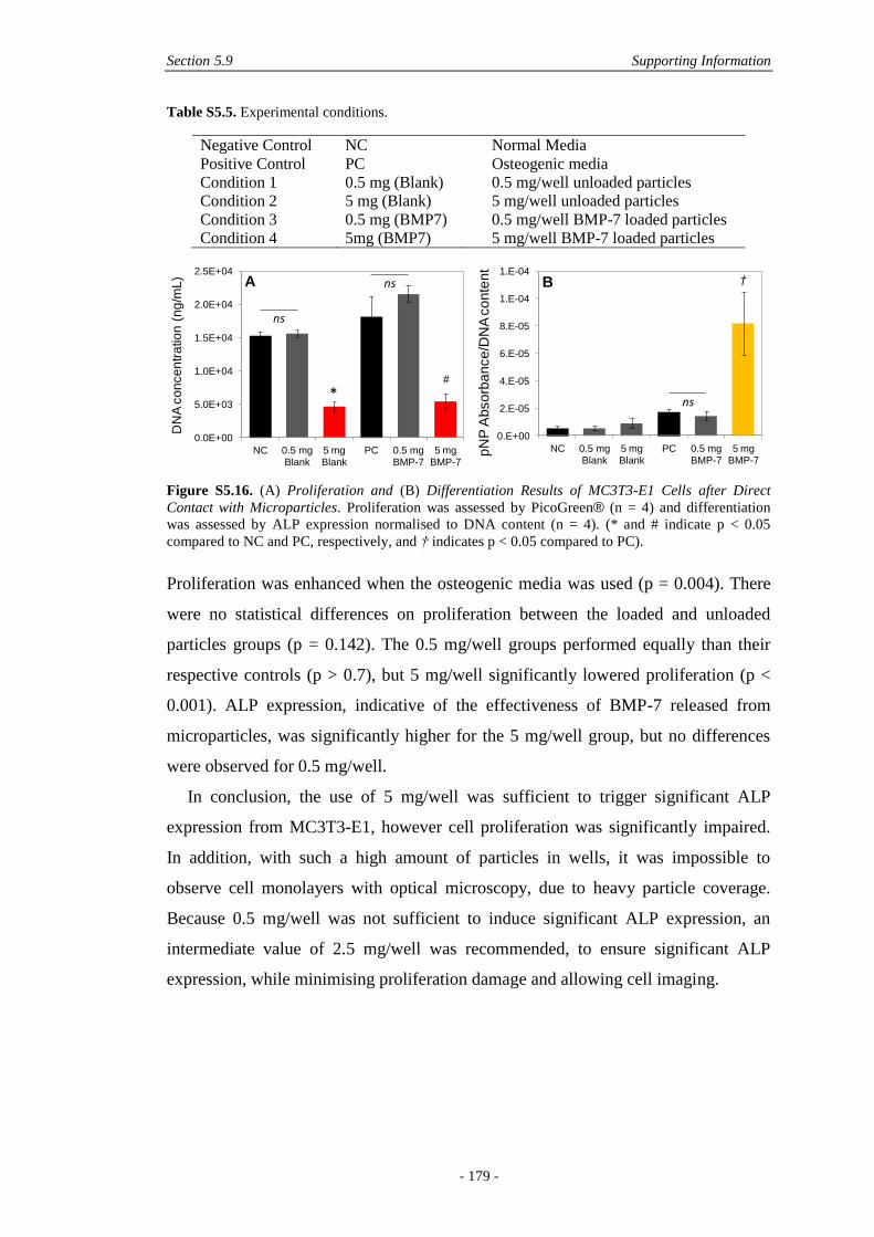
Section 5.9 Supporting Information
- 179 -
Table S5.5. Experimental conditions.
Negative Control NC Normal Media
Positive Control PC Osteogenic media
Condition 1 0.5 mg (Blank) 0.5 mg/well unloaded particles
Condition 2 5 mg (Blank) 5 mg/well unloaded particles
Condition 3 0.5 mg (BMP7) 0.5 mg/well BMP-7 loaded particles
Condition 4 5mg (BMP7) 5 mg/well BMP-7 loaded particles
Figure S5.16. (A) Proliferation and (B) Differentiation Results of MC3T3-E1 Cells after Direct
Contact with Microparticles. Proliferation was assessed by PicoGreen® (n = 4) and differentiation
was assessed by ALP expression normalised to DNA content (n = 4). (* and # indicate p < 0.05
compared to NC and PC, respectively, and † indicates p < 0.05 compared to PC).
Proliferation was enhanced when the osteogenic media was used (p = 0.004). There
were no statistical differences on proliferation between the loaded and unloaded
particles groups (p = 0.142). The 0.5 mg/well groups performed equally than their
respective controls (p > 0.7), but 5 mg/well significantly lowered proliferation (p <
0.001). ALP expression, indicative of the effectiveness of BMP-7 released from
microparticles, was significantly higher for the 5 mg/well group, but no differences
were observed for 0.5 mg/well.
In conclusion, the use of 5 mg/well was sufficient to trigger significant ALP
expression from MC3T3-E1, however cell proliferation was significantly impaired.
In addition, with such a high amount of particles in wells, it was impossible to
observe cell monolayers with optical microscopy, due to heavy particle coverage.
Because 0.5 mg/well was not sufficient to induce significant ALP expression, an
intermediate value of 2.5 mg/well was recommended, to ensure significant ALP
expression, while minimising proliferation damage and allowing cell imaging.
0.0E+00
5.0E+03
1.0E+04
1.5E+04
2.0E+04
2.5E+04
NC 0.5 mg Blank
5 mg Blank
PC 0.5 mg BMP-7
5 mg BMP-7
DN
A c
on
ce
ntr
atio
n (
ng
/mL
)
*#
ns
ns
0.E+00
2.E-05
4.E-05
6.E-05
8.E-05
1.E-04
1.E-04
NC 0.5 mg Blank
5 mg Blank
PC 0.5 mg BMP-7
5 mg BMP-7
pN
P A
bso
rba
nce
/DN
A c
on
ten
t
†
ns
A B
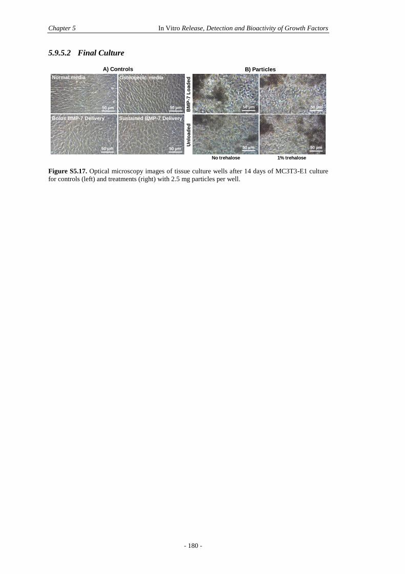
Chapter 5 In Vitro Release, Detection and Bioactivity of Growth Factors
- 180 -
5.9.5.2 Final Culture
Figure S5.17. Optical microscopy images of tissue culture wells after 14 days of MC3T3-E1 culture
for controls (left) and treatments (right) with 2.5 mg particles per well.
Normal media Osteogenic media
Bolus BMP-7 Delivery Sustained BMP-7 Delivery
BM
P-7
Lo
ad
ed
No trehalose
A) Controls B) Particles
Un
loa
de
d
1% trehalose
50 µm 50 µm
50 µm 50 µm
50 µm 50 µm
50 µm 50 µm
- 181 -
Chapter 6: Composites for Delivery of
Therapeutics: Combining Melt
Electrospun Scaffolds with Loaded
Electrosprayed Microparticles
Nathalie Bock1,3,4
, Maria A. Woodruff1, Roland Steck
2, Dietmar W.
Hutmacher3, Brooke L. Farrugia
4, Tim R. Dargaville
4
Published in Macromolecular Bioscience, Volume 14, Issue 2, 2014, Pages 202-
2014.
© 2013 WILEY-VCH Verlag GmbH & Co. KGaA, Weinheim. All rights reserved.
Statement of contribution of co-authors for thesis by published papers
Contributors Statement of contribution
Nathalie Bock Developed the research questions
Designed and performed most experiments
Analysed and interpreted the results
Conceived and wrote the manuscript
Maria A. Woodruff* Involved in the conception of the project
Provided feedback on manuscript
Roland Steck* Performed µCT experiments and analysis
1 Biomaterials and Tissue Morphology Group
2 Trauma Research Group
3 Regenerative Medicine Group
4 Tissue Repair and Regeneration Group
Institute of Health and Biomedical Innovation, Queensland University of Technology,
60 Musk Avenue, Kelvin Grove, QLD 4059, Australia
Chapter 6 Electrosprayed/Electrospun Composites for Delivery ofTherapeutics
- 182 -
Dietmar W. Hutmacher* Involved in the conception of the project
Provided feedback on manuscript
Brooke L. Farrugia* Assisted in release sample collection
Provided some technical guidance
Provided feedback on manuscript
Tim R. Dargaville* Involved in the conception of the project
Conceived aspects of the experimental design
Assisted in GPC and DSC analysis
Provided feedback on manuscript
The authors listed above have certified* that:
6. they meet the criteria for authorship in that they have participated in the
conception, execution, or interpretation, of at least that part of the publication in
their field of expertise;
7. they take public responsibility for their part of the publication, except for the
responsible author who accepts overall responsibility for the publication;
8. there are no other authors of the publication according to these criteria;
9. potential conflicts of interest have been disclosed to (a) granting bodies, (b) the
editor or publisher of journals or other publications, and (c) the head of the
responsible academic unit, and
10. they agree to the use of the publication in the student’s thesis and its publication
on the QUT ePrints database consistent with any limitations set by publisher
requirements.
Principal Supervisor Confirmation
I have sighted email or other correspondence from all Co-authors confirming their
certifying authorship.
Section 6.1 Abstract
- 183 -
6.1 ABSTRACT
Delivery of therapeutics from structural scaffolds is an emerging strategy for guiding
cells towards regeneration of tissues, however difficulties arise when encapsulating
therapeutics directly within scaffolds. Here a novel strategy is reported to produce
polycaprolactone microfibre-scaffolds independently layered with high densities of
poly(lactic-co-glycolic acid) microparticles encapsulating a model protein. The use
of melt electrospun scaffolds confers high porosity while direct electrospraying
provides reproducible scaffold coating throughout the entire architecture. The burst
release is significantly reduced when compared with release from microparticles free
in solution, due to the immobilisation of microparticles on the surface of the scaffold.
The degradation of microparticles is dependent on protein-polymer interactions,
influencing the release mechanisms. The novel composite scaffolds have a positive
biological effect in contact with precursor osteoblast cells up to 18 days in culture.
The scaffold design achieved with the techniques presented here makes these new
composite scaffolds promising templates for growth factor delivery.
6.2 KEYWORDS
Electrospraying, drug delivery, polymer-drug interactions, microstructures, tissue
engineering.
6.3 INTRODUCTION
Biodegradable polymeric scaffolds have become crucial in the arena of tissue
engineering (TE), where they provide a temporary porous structure for a specific
tissue to re-grow [213]. Fibre-based scaffolds have been extensively studied for this
purpose based on the popularity of electrospinning technologies for the fabrication of
fibres on the nano- to micron scale with good control over the physico-chemical
properties [143, 214]. Scaffold porosity and architecture, as well as fibre diameter
and fibre arrangement are essential variables enabling cell invasiveness [21, 131].
Such properties can reproducibly be controlled by electrospinning polymer solutions
and melts [215], in static and direct writing modes [216-218]. While electrospun
matrices may provide physical cues for cells, there is also a need to deliver biological

Chapter 6 Electrosprayed/Electrospun Composites for Delivery ofTherapeutics
- 184 -
cues that effectively direct cellular growth and differentiation, for the regeneration of
complex tissues such as skin, cartilage and bone [219]. This can be achieved by
delivering exogenous bioactive molecules, for instance growth factors (GF), which
are embedded within fibres and available for cellular uptake upon matrix degradation
[22-24]. While many studies have considered this issue, as reviewed by Szentivanyi
et al. [20], the direct incorporation of proteins into fibres is not yet optimised for
load-bearing scaffolds, as required in bone TE for instance, where GFs should ideally
be sustainably released over many weeks, while the scaffold can still maintain its
structural function [145, 220]. The addition of proteins directly to electrospinning
solutions can also result in poor fibre mesh properties and instabilities in the cone-jet
[25, 104]. To overcome these limitations, one approach is to incorporate a separate
release system into the scaffold [24, 181].
Polymeric nano- and microparticles are suitable candidates for incorporation
into/onto TE constructs since both scaffold structure and GF release requirements
can be taken into account [18]. One advantage of encapsulating GFs is that multiple
GF release profiles can be achieved by judicious choice of polymers’ properties and
processing parameters [16]. For instance, bone morphogenetic protein-2 (BMP-2)
and insulin-like GF-1 (IGF-1) have been simultaneously delivered from
microparticles embedded in a hydrogel scaffold demonstrating different release
patterns [146]. The secure fixation of loaded particles to fibre-based scaffolds,
however, remains a challenge, but is an important consideration to prevent particle
loss during implantation [24]. Ionescu et al. have previously reported dual fabrication
techniques that enabled loaded microparticles to be successfully incorporated into
polycaprolactone (PCL) electrospun nanofibres [144]. To do this, they
simultaneously electrospun PCL with a sacrificial solution of polyethylene oxide
(PEO), containing the loaded particles. Upon removal of the PEO, the microparticles
remained entrapped within the PCL nanofibres [144]. Similarly, a co-
electrospraying/electrospinning strategy reported by Wang et al. allowed the direct
formation of a scaffold from polyurethaneurea nanofibres and poly(lactic-co-glycolic
acid) (PLGA) microcapsules containing an IGF-1 gelatin solution [29]. While this
approach provided interesting morphologies, only low densities of particles could be
loaded and thus minimal IGF-1 was released from the nanofibres [29].
Electrospraying is an emerging strategy to load therapeutic molecules into
polymeric particles [181]. While the electrospraying process follows the same
Section 6.4 Experimental Section
- 185 -
principles of solution electrospinning, the polymer concentration used is below a
critical concentration which would be required to form fibres and as such, this results
in the jet breaking up into droplets [102]. Electrospraying provides high control over
particle size distributions and morphology with control of polymer solution and
processing parameters [83, 221]. A large variety of molecules can be encapsulated in
electrosprayed particles, such as anti-cancer and inhalation drugs, antibiotics,
proteins and GFs [64]. In the context of fibre-scaffolds, we hypothesise that
electrospraying may be used to directly coat fibres with loaded particles without the
use of additives, while conferring high control over the characteristics of the final
particles.
Here we present unique composite scaffolds which incorporate a microparticle
protein-delivery system produced using electrospraying directly onto melt
electrospun scaffolds. The use of microfibre-scaffolds produced by melt
electrospinning allows for a greater degree of pore size and interconnectivity
available for particle loading than is possible with solution electrospun nanofibres
[218], meaning that high densities of loaded microparticles can be incorporated into
the final scaffolds. The steps involved in optimising a homogenous coating and high
yield of PLGA microparticles loaded with serum albumin (SA) onto PCL microfibres
and the final physical properties of the constructs are described hereafter. SA release
profiles and degradation characteristics of composite scaffolds in solution are
reported over 4 months and compared with free electrosprayed particles which are
not attached to the scaffolds. Preliminary positive biological effects of composites
scaffolds on precursor osteoblast cells are assessed in vitro up to 18 days.
6.4 EXPERIMENTAL SECTION
6.4.1 Scaffold Fabrication
6.4.1.1 Materials
Poly(lactic-co-glycolic acid) 85:15 (Mn 41.3 kg/mol, PDI 1.6) was purchased from
Evonik Industries, USA. Dichloromethane (DCM) and serum albumin (SA) were
purchased from Sigma-Aldrich, Australia. Polycaprolactone (Mn 41 kg/mol, PDI
1.78) was donated by Perstorp Ltd, UK.
Chapter 6 Electrosprayed/Electrospun Composites for Delivery ofTherapeutics
- 186 -
6.4.1.2 Raw Scaffold Fabrication
Melt PCL scaffolds (14 mm diameter) were produced using an in–house built
apparatus with a circulating water system as a heater described elsewhere [222]. PCL
was heated at 70°C, electrospun at a 10 µL/h flow rate from a plastic Luer-lock 2 mL
syringe (B-Braun, Australia) fitted with a blunt 23 G needle placed 30 mm above a
grounded aluminium plate while a voltage of 6 kV was applied to the needle tip. The
resultant scaffolds were placed in 70% ethanol (EtOH) for 30 min under vacuum,
followed by immersion in sodium hydroxide (NaOH) 2 M for 1 h at 37°C to reduce
surface hydrophobicity. The scaffolds were then rinsed with deionised water until the
pH level dropped to 7. Finally, scaffolds were placed in phosphate buffer saline
(PBS) for 30 min and dried.
6.4.1.3 Composite Scaffold Fabrication
Composite scaffolds were obtained by direct electrospraying onto melt scaffolds.
Five PCL scaffolds were fixed with conductive double-face carbon tape on a
grounded aluminium disc, 48 mm in diameter, or 150 × 150 mm2 aluminium plate
recovered with aluminium foil, placed 150 mm away from the tip (depicted
schematically in Figure S6.8, supporting information). Reproducible PLGA
microparticles were generated by working in the semi-dilute entangled regime of
electrospraying [181]. Briefly, PLGA was dissolved in DCM (10% wt/v), loaded in a
1 mL glass syringe (Hamilton, USA) and extruded through a 21 G blunt needle at a
rate of 0.8 mL/h from a syringe pump (WPI, USA), while a voltage of 10 kV was
applied to the needle tip. For SA loading, the PLGA solution was added to
lyophilised SA under magnetic stirring (10% wt/v PLGA loaded with 1% wt SA).
The resultant dispersion was probe sonicated for 60 s at 0.5 W (Misonix 3,000,
USA). Conductivity was measured using a conductivity meter (TPS 900C,
Australia). The dispersion was electrosprayed in the same conditions as the SA-free
polymer solution. All scaffolds and particles were placed in a dessicator under pump-
aided vacuum overnight and stored at -18°C until further use.
6.4.2 Physical Characterisation
6.4.2.1 Size
Particle size was assessed with ImageJ analysis software (National Institutes of
Health (NIH)) based on scanning electron microscope (SEM) micrographs. 6 random
composite scaffolds were selected per condition and 30 particles were measured per
Section 6.4 Experimental Section
- 187 -
scaffold (n = 30/scaffold). 4 random samples of collected particles were selected and
45 particles were measured (n = 45/sample). Fibre size was measured identically on
raw PCL scaffolds, where 6 scaffolds were selected and 40 fibres were measured (n
= 40/scaffold).
6.4.2.2 Morphology and Microstructure
Morphology was assessed by SEM and micro-computed tomography (µCT). For
SEM, materials were taped on aluminium stubs and gold coated for 225 s at 30 mA
(SC500, Bio-Rad, Australia). The morphology and microstructure of scaffolds were
characterised with a FEI Quanta 200 SEM operating at 10 kV in high vacuum mode.
For µCT, scaffolds were scanned (µCT 40, Scanco Medical, Switzerland) in air at an
energy of 45 kVp and intensity of 177 µA with 300 ms integration time. The scans
were reconstructed to 3D datasets with an isotropic voxel size of 6 µm. After
segmentation, the average fibre spacing was determined by applying a bone
morphometric analysis algorithm using the distance transformation method [223]
with the scanner’s software (µCT Evaluation Program V6.5-1, Scanco Medical,
Switzerland). Scaffold porosity was obtained by determining the ratio of volume
occupied by the fibres and particles to the total volume scanned. The results were
expressed as means ± 1 standard deviation (SD).
6.4.3 In Vitro Characterisation
6.4.3.1 SA Content
SA content in the particles was determined by an extraction procedure. Particles (20
mg) were dissolved in DCM (1 mL), n = 4. PBS (3 mL) was added to the dispersions
and tubes were vortexed for 30 s to extract the SA. The resultant emulsions were
centrifuged at 5,000 rpm for 15 min and left overnight. The aqueous phase was
collected and another extraction cycle was performed. SA content was determined by
the micro-bicinchoninic acid (µBCA) assay (Thermo Fisher Scientific, USA).
Encapsulation efficiency (%) was measured as: [Actual SA content
(µg)]/[Theoretical SA content]×100.
6.4.3.2 Release Studies
In vitro release studies were performed by placing particles and composites that
contained the same amount of particles (8.5 mg), SA-free and SA-loaded, in 2 mL
screw-capped microtubes with PBS (1 mL), n = 3. Tubes were agitated at a speed of
Chapter 6 Electrosprayed/Electrospun Composites for Delivery ofTherapeutics
- 188 -
8 rpm at 37°C for 130 days. At specific time points, tubes were centrifuged at 14,000
rpm for 5 min to settle particles before 970 µL of supernatant was collected and
replaced by the same amount of fresh PBS. The supernatant was analysed by the
µBCA assay (Thermo Fisher Scientific, USA). A standard curve was prepared by
serial dilutions of the supplied SA from 40 to 0 µg/mL. A polynomial fit was
deducted from the corresponding absorbance readings at 562 nm (R2 = 0.9989)
(Microplate Manager V5.2, Benchmark Plus spectrophotometer, Bio-Rad, USA).
The absorbance measured from released SA was normalised to the reading from SA-
free particles/scaffolds degraded to the same time point, in order to account for the
presence of PLGA degradation products in the release media.
6.4.3.3 Polymer Degradation
Degradation was assessed by placing the same materials and amounts as for release
studies in PBS, under the same conditions. 3 scaffolds and 3 samples of collected
particles were assessed at each time point (n = 3) and uncoated raw PCL scaffolds
were assessed as well. While 970 µL of PBS was replaced for all samples at all time
points, the samples from each specific time point were washed twice with water,
centrifuged at 14,000 rpm for 5 min, and vacuum-dried. Mass loss was determined
gravimetrically as % Mass Loss = [(M1-M2)/M1] ×100, where M1 was the initial mass
and M2 the final mass of particles. Number-average molecular weight (Mn), weight-
average molecular weight (Mw) and polydispersity were determined by gel
permeation chromatography (GPC) in chloroform. All samples were dissolved in
chloroform and SA-loaded samples were further filtered (0.45 µm pore). Solutions
were injected (250 µL) onto Styragel HR columns with a flow rate operating at 1
mL/min. Calibration was done by the use of polystyrene standards ranging from
1,350 to 382.1 kg/mol. Glass transitions of free particles were measured by
differential scanning calorimetry (DSC) on a TA instruments Q100 DSC instrument.
Samples (1-6 mg) were scanned twice from 0°C to 250°C at a heating/cooling rate of
20°C/min. Degraded morphology was assessed by SEM under the same conditions as
non-degraded samples.
6.4.3.4 Statistical Analysis
Statistical analysis was performed with PASW Statistics 18. For size, analysis was
done on means using an independent Student’s t-test assuming equal variances, after
Levene’s test confirmed equality of variances (0.411). For SA content, a Mann-
Section 6.4 Experimental Section
- 189 -
Whitney non-parametric test was done on medians. The significance level was
determined for p < 0.05.
6.4.4 Biological Evaluation
6.4.4.1 Cell Culture
The biological effect of scaffolds produced here was assessed with a mouse
osteoblast precursor cell line, MC3T3-E1 (passage 9). Prior to cell seeding, MC3T3
cells were cultured in growth medium: α-MEM cell culture medium supplemented
with 10% foetal calf serum (FCS), and 1% penicillin/streptomycin (P/S) (all from
Invitrogen, Australia) at 37°C and 5% CO2. All scaffolds were cut into 3 symmetrical
samples and weighed. Scaffolds were rinsed with 70% EtOH and sterilised under
ultraviolet (UV) radiation for 20 min on each side. Dry, sterile scaffolds were
transferred into 24-well plates and incubated each for 1 h with 20 µL of serum-free
medium. MC3T3 cells (4,500) suspended in culture medium (40 µL) were equally
distributed onto each scaffold using a top seeding static method. Cell-scaffold
constructs were incubated for 2 h at 37°C, during which initial cell attachment to the
scaffolds occurred. Culture medium (1 mL) was then carefully added to each well.
MC3T3 cells were maintained in 5% CO2 at 37°C for 18 days in a humidified
incubator. Medium was changed every 2-3 days and selected constructs were fixed
and prepared for analysis as described below after 24 h, 9 days and 18 days of cell
culture.
6.4.4.2 Cell Viability
Cell viability was assessed by a LIVE/DEAD staining assay with fluorescein
diacetate (FDAC) and propidium iodide (PI) (both from Invitrogen).[224] Cell-
scaffold constructs were washed twice with PBS, followed by incubation in FDAC
(0.67 µg/mL) and PI (5 µg/mL) solution (1 mL) for 5 min at 37°C in the dark. After
washing with PBS, specimens were immediately imaged using a Zeiss Axio M2
Imager (Zeiss, Germany) fluorescent microscope.
6.4.4.3 Cell Morphology
The morphology of actin fibres and nuclei of MC3T3 cells on the scaffolds was
visualised using confocal laser scanning microscopy (CLSM). Cell-scaffold
constructs were removed from the media, washed twice with PBS (containing Mg2+
and Ca2+
), fixed in paraformaldehyde (4%) for 20 min at room temperature (RT),
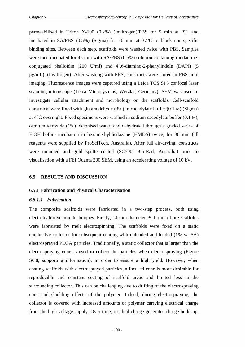
Chapter 6 Electrosprayed/Electrospun Composites for Delivery ofTherapeutics
- 190 -
permeabilised in Triton X-100 (0.2%) (Invitrogen)/PBS for 5 min at RT, and
incubated in SA/PBS (0.5%) (Sigma) for 10 min at 37°C to block non-specific
binding sites. Between each step, scaffolds were washed twice with PBS. Samples
were then incubated for 45 min with SA/PBS (0.5%) solution containing rhodamine-
conjugated phalloidin (200 U/ml) and 4’,6-diamino-2-phenylindole (DAPI) (5
μg/mL), (Invitrogen). After washing with PBS, constructs were stored in PBS until
imaging. Fluorescence images were captured using a Leica TCS SP5 confocal laser
scanning microscope (Leica Microsystems, Wetzlar, Germany). SEM was used to
investigate cellular attachment and morphology on the scaffolds. Cell-scaffold
constructs were fixed with glutaraldehyde (3%) in cacodylate buffer (0.1 M) (Sigma)
at 4°C overnight. Fixed specimens were washed in sodium cacodylate buffer (0.1 M),
osmium tetroxide (1%), deionised water, and dehydrated through a graded series of
EtOH before incubation in hexamethyldisilazane (HMDS) twice, for 30 min (all
reagents were supplied by ProSciTech, Australia). After full air-drying, constructs
were mounted and gold sputter-coated (SC500, Bio-Rad, Australia) prior to
visualisation with a FEI Quanta 200 SEM, using an accelerating voltage of 10 kV.
6.5 RESULTS AND DISCUSSION
6.5.1 Fabrication and Physical Characterisation
6.5.1.1 Fabrication
The composite scaffolds were fabricated in a two-step process, both using
electrohydrodynamic techniques. Firstly, 14 mm diameter PCL microfibre scaffolds
were fabricated by melt electrospinning. The scaffolds were fixed on a static
conductive collector for subsequent coating with unloaded and loaded (1% wt SA)
electrosprayed PLGA particles. Traditionally, a static collector that is larger than the
electrospraying cone is used to collect the particles when electrospraying (Figure
S6.8, supporting information), in order to ensure a high yield. However, when
coating scaffolds with electrosprayed particles, a focused cone is more desirable for
reproducible and constant coating of scaffold areas and limited loss to the
surrounding collector. This can be challenging due to drifting of the electrospraying
cone and shielding effects of the polymer. Indeed, during electrospraying, the
collector is covered with increased amounts of polymer carrying electrical charge
from the high voltage supply. Over time, residual charge generates charge build-up,
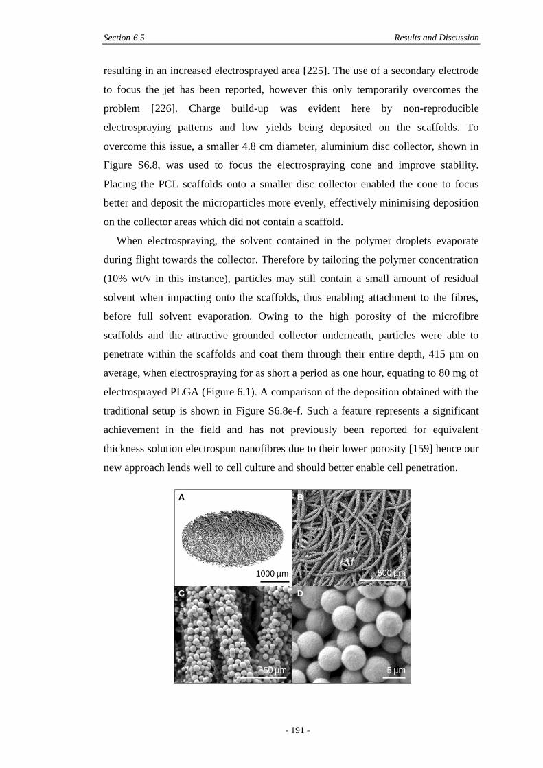
Section 6.5 Results and Discussion
- 191 -
resulting in an increased electrosprayed area [225]. The use of a secondary electrode
to focus the jet has been reported, however this only temporarily overcomes the
problem [226]. Charge build-up was evident here by non-reproducible
electrospraying patterns and low yields being deposited on the scaffolds. To
overcome this issue, a smaller 4.8 cm diameter, aluminium disc collector, shown in
Figure S6.8, was used to focus the electrospraying cone and improve stability.
Placing the PCL scaffolds onto a smaller disc collector enabled the cone to focus
better and deposit the microparticles more evenly, effectively minimising deposition
on the collector areas which did not contain a scaffold.
When electrospraying, the solvent contained in the polymer droplets evaporate
during flight towards the collector. Therefore by tailoring the polymer concentration
(10% wt/v in this instance), particles may still contain a small amount of residual
solvent when impacting onto the scaffolds, thus enabling attachment to the fibres,
before full solvent evaporation. Owing to the high porosity of the microfibre
scaffolds and the attractive grounded collector underneath, particles were able to
penetrate within the scaffolds and coat them through their entire depth, 415 µm on
average, when electrospraying for as short a period as one hour, equating to 80 mg of
electrosprayed PLGA (Figure 6.1). A comparison of the deposition obtained with the
traditional setup is shown in Figure S6.8e-f. Such a feature represents a significant
achievement in the field and has not previously been reported for equivalent
thickness solution electrospun nanofibres due to their lower porosity [159] hence our
new approach lends well to cell culture and should better enable cell penetration.
1000 µm 500 µm
5 µm
A B
C D
50 µm
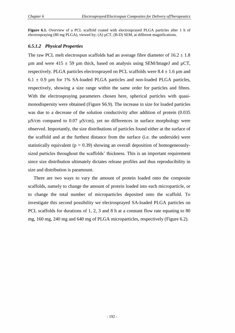
Chapter 6 Electrosprayed/Electrospun Composites for Delivery ofTherapeutics
- 192 -
Figure 6.1. Overview of a PCL scaffold coated with electrosprayed PLGA particles after 1 h of
electrospraying (80 mg PLGA), viewed by; (A) µCT, (B-D) SEM, at different magnifications.
6.5.1.2 Physical Properties
The raw PCL melt electrospun scaffolds had an average fibre diameter of 16.2 ± 1.8
µm and were 415 ± 59 µm thick, based on analysis using SEM/ImageJ and µCT,
respectively. PLGA particles electrosprayed on PCL scaffolds were 8.4 ± 1.6 µm and
6.1 ± 0.9 µm for 1% SA-loaded PLGA particles and non-loaded PLGA particles,
respectively, showing a size range within the same order for particles and fibres.
With the electrospraying parameters chosen here, spherical particles with quasi-
monodispersity were obtained (Figure S6.9). The increase in size for loaded particles
was due to a decrease of the solution conductivity after addition of protein (0.035
µS/cm compared to 0.07 µS/cm), yet no differences in surface morphology were
observed. Importantly, the size distributions of particles found either at the surface of
the scaffold and at the furthest distance from the surface (i.e. the underside) were
statistically equivalent (p = 0.39) showing an overall deposition of homogeneously-
sized particles throughout the scaffolds’ thickness. This is an important requirement
since size distribution ultimately dictates release profiles and thus reproducibility in
size and distribution is paramount.
There are two ways to vary the amount of protein loaded onto the composite
scaffolds, namely to change the amount of protein loaded into each microparticle, or
to change the total number of microparticles deposited onto the scaffold. To
investigate this second possibility we electrosprayed SA-loaded PLGA particles on
PCL scaffolds for durations of 1, 2, 3 and 8 h at a constant flow rate equating to 80
mg, 160 mg, 240 mg and 640 mg of PLGA microparticles, respectively (Figure 6.2).
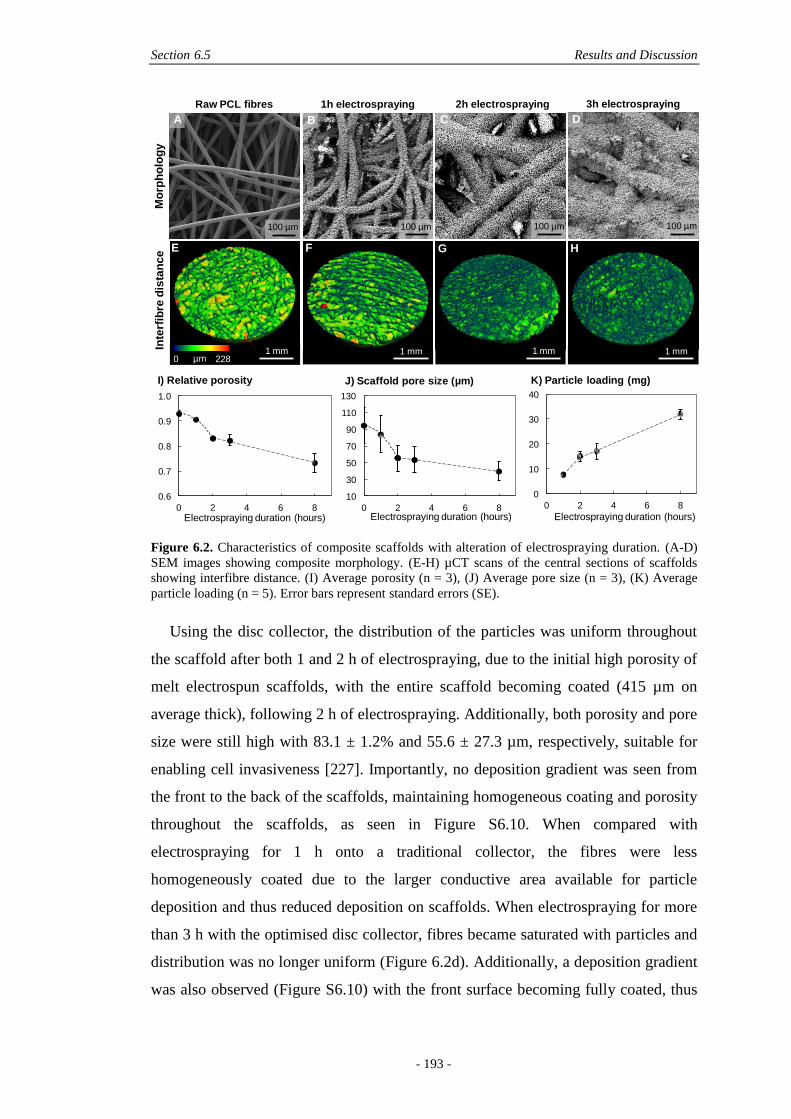
Section 6.5 Results and Discussion
- 193 -
Figure 6.2. Characteristics of composite scaffolds with alteration of electrospraying duration. (A-D)
SEM images showing composite morphology. (E-H) µCT scans of the central sections of scaffolds
showing interfibre distance. (I) Average porosity (n = 3), (J) Average pore size (n = 3), (K) Average
particle loading (n = 5). Error bars represent standard errors (SE).
Using the disc collector, the distribution of the particles was uniform throughout
the scaffold after both 1 and 2 h of electrospraying, due to the initial high porosity of
melt electrospun scaffolds, with the entire scaffold becoming coated (415 µm on
average thick), following 2 h of electrospraying. Additionally, both porosity and pore
size were still high with 83.1 ± 1.2% and 55.6 ± 27.3 µm, respectively, suitable for
enabling cell invasiveness [227]. Importantly, no deposition gradient was seen from
the front to the back of the scaffolds, maintaining homogeneous coating and porosity
throughout the scaffolds, as seen in Figure S6.10. When compared with
electrospraying for 1 h onto a traditional collector, the fibres were less
homogeneously coated due to the larger conductive area available for particle
deposition and thus reduced deposition on scaffolds. When electrospraying for more
than 3 h with the optimised disc collector, fibres became saturated with particles and
distribution was no longer uniform (Figure 6.2d). Additionally, a deposition gradient
was also observed (Figure S6.10) with the front surface becoming fully coated, thus
0
10
20
30
40
0 2 4 6 8
Electrospraying duration (hours)
10
30
50
70
90
110
130
0 2 4 6 8Electrospraying duration (hours)
Raw PCL fibres 1h electrospraying 2h electrospraying 3h electrospraying
0 228µm
Mo
rph
olo
gy
Inte
rfib
red
ista
nc
e
100 µm
1 mm 1 mm 1 mm 1 mm
0.6
0.7
0.8
0.9
1.0
0 2 4 6 8Electrospraying duration (hours)
A B C D
E F G H
I) Relative porosity J) Scaffold pore size (µm) K) Particle loading (mg)
100 µm 100 µm 100 µm
Chapter 6 Electrosprayed/Electrospun Composites for Delivery ofTherapeutics
- 194 -
blocking the porosity which would otherwise enable further coating of deeper parts
of the scaffolds. This could be correlated with µCT measurements (Figure 6.2e-k)
where a decrease in porosity and pore size was observed for the first 2 hours of
electrospraying (160 mg of electrosprayed PLGA) but slowed following further
electrospraying, attributed to the surface porosity reduction not allowing particles to
penetrate through to the centre of the scaffolds. This was evidenced by measuring the
total yield YT, which refers to the amount of particles deposited on the collector
compared to the initial amount of electrosprayed material (Equation 6.1):
( ) ( )
( ) (6.1)
YT was similar for 1, 2 and 3 h of electrospraying, namely 68.9%, 72.6%, and 67.6%,
respectively, however, a yield of only 47.6% was measured for electrospraying for 8
h, showing that fewer particles were deposited onto the collector for prolonged
coating. This phenomenon was attributed to charge build-up, since the collector was
heavily coated with particles at this stage, resulting in particle deposition on non-
charged surfaces, i.e. apparatus housing and surrounding equipment. Importantly,
particle size and morphology remained identical for any given electrospraying
duration and were not affected by charge build-up.
The electrospraying process efficiency was assessed by considering the scaffold
yield, YS, which is the amount of particles on the scaffold area compared to the total
amount of particles deposited on the collector (Equation 6.2):
( ) ( )
( ) (6.2)
When electrospraying on a traditional 150 × 150 mm2 aluminium foil collector
(Figure S6.8b), YS was higher for SA-free particles (YS = 12.4%) compared with SA-
loaded particles (YS = 3.9%) after electrospraying for 1 h. These low yields illustrate
an effect from the type of solution electrosprayed (loaded, non-loaded) due to
conductivity differences. However, when the small disc collector was used, YS was
higher, namely 44.0 ± 5.1% and 42.0 ± 4.4% for SA-free and SA-loaded particles,
respectively, thus independent of solution conductivity and also independent of
electrospraying duration. This was consistent with the area occupied by scaffolds,
namely 42.5% of the collector, showing homogenous and non-preferential coating of
both scaffolds and collector areas.
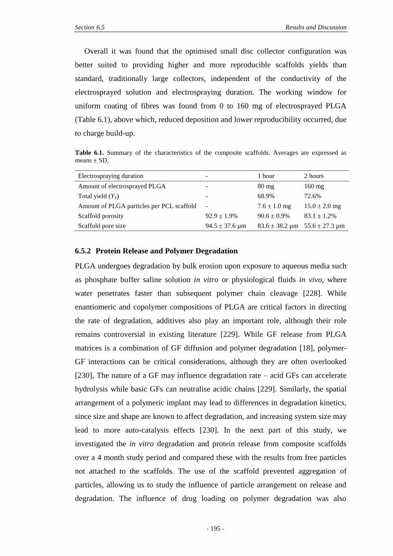
Section 6.5 Results and Discussion
- 195 -
Overall it was found that the optimised small disc collector configuration was
better suited to providing higher and more reproducible scaffolds yields than
standard, traditionally large collectors, independent of the conductivity of the
electrosprayed solution and electrospraying duration. The working window for
uniform coating of fibres was found from 0 to 160 mg of electrosprayed PLGA
(Table 6.1), above which, reduced deposition and lower reproducibility occurred, due
to charge build-up.
Table 6.1. Summary of the characteristics of the composite scaffolds. Averages are expressed as
means ± SD.
Electrospraying duration - 1 hour 2 hours
Amount of electrosprayed PLGA - 80 mg 160 mg
Total yield (YT) - 68.9% 72.6%
Amount of PLGA particles per PCL scaffold - 7.6 ± 1.0 mg 15.0 ± 2.0 mg
Scaffold porosity 92.9 ± 1.9% 90.6 ± 0.9% 83.1 ± 1.2%
Scaffold pore size 94.5 ± 37.6 µm 83.6 ± 38.2 µm 55.6 ± 27.3 µm
6.5.2 Protein Release and Polymer Degradation
PLGA undergoes degradation by bulk erosion upon exposure to aqueous media such
as phosphate buffer saline solution in vitro or physiological fluids in vivo, where
water penetrates faster than subsequent polymer chain cleavage [228]. While
enantiomeric and copolymer compositions of PLGA are critical factors in directing
the rate of degradation, additives also play an important role, although their role
remains controversial in existing literature [229]. While GF release from PLGA
matrices is a combination of GF diffusion and polymer degradation [18], polymer-
GF interactions can be critical considerations, although they are often overlooked
[230], The nature of a GF may influence degradation rate – acid GFs can accelerate
hydrolysis while basic GFs can neutralise acidic chains [229]. Similarly, the spatial
arrangement of a polymeric implant may lead to differences in degradation kinetics,
since size and shape are known to affect degradation, and increasing system size may
lead to more auto-catalysis effects [230]. In the next part of this study, we
investigated the in vitro degradation and protein release from composite scaffolds
over a 4 month study period and compared these with the results from free particles
not attached to the scaffolds. The use of the scaffold prevented aggregation of
particles, allowing us to study the influence of particle arrangement on release and
degradation. The influence of drug loading on polymer degradation was also
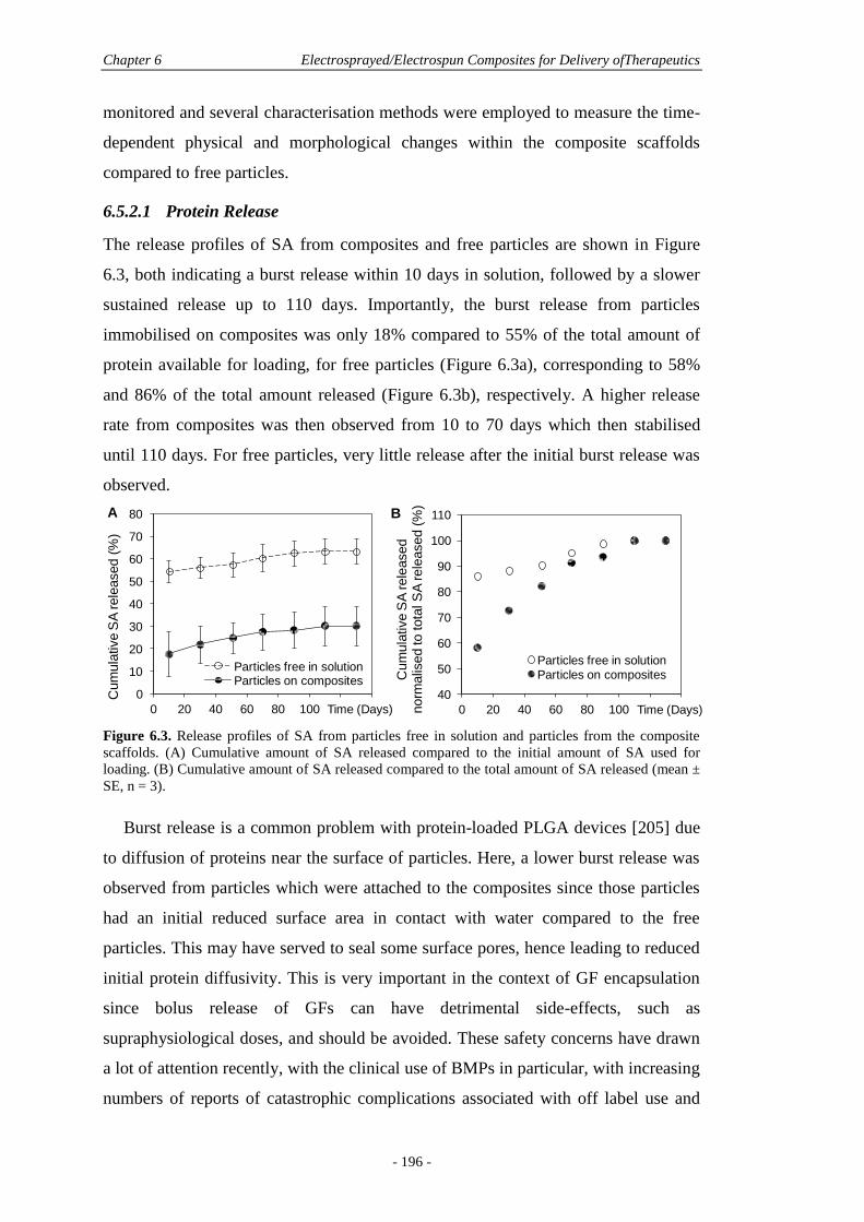
Chapter 6 Electrosprayed/Electrospun Composites for Delivery ofTherapeutics
- 196 -
monitored and several characterisation methods were employed to measure the time-
dependent physical and morphological changes within the composite scaffolds
compared to free particles.
6.5.2.1 Protein Release
The release profiles of SA from composites and free particles are shown in Figure
6.3, both indicating a burst release within 10 days in solution, followed by a slower
sustained release up to 110 days. Importantly, the burst release from particles
immobilised on composites was only 18% compared to 55% of the total amount of
protein available for loading, for free particles (Figure 6.3a), corresponding to 58%
and 86% of the total amount released (Figure 6.3b), respectively. A higher release
rate from composites was then observed from 10 to 70 days which then stabilised
until 110 days. For free particles, very little release after the initial burst release was
observed.
Figure 6.3. Release profiles of SA from particles free in solution and particles from the composite
scaffolds. (A) Cumulative amount of SA released compared to the initial amount of SA used for
loading. (B) Cumulative amount of SA released compared to the total amount of SA released (mean ±
SE, n = 3).
Burst release is a common problem with protein-loaded PLGA devices [205] due
to diffusion of proteins near the surface of particles. Here, a lower burst release was
observed from particles which were attached to the composites since those particles
had an initial reduced surface area in contact with water compared to the free
particles. This may have served to seal some surface pores, hence leading to reduced
initial protein diffusivity. This is very important in the context of GF encapsulation
since bolus release of GFs can have detrimental side-effects, such as
supraphysiological doses, and should be avoided. These safety concerns have drawn
a lot of attention recently, with the clinical use of BMPs in particular, with increasing
numbers of reports of catastrophic complications associated with off label use and
0
10
20
30
40
50
60
70
80
0 20 40 60 80 100 120 140
Cum
ula
tive S
A rele
ased (
%)
Time (Days)
Particles free in solutionParticles on composites
A B
40
50
60
70
80
90
100
110
0 20 40 60 80 100 120 140
Cum
ula
tive S
A rele
ased
norm
alis
ed
to tota
l S
A rele
ased (
%)
Time (Days)
Particles free in solutionParticles on composites
Section 6.5 Results and Discussion
- 197 -
high doses [13, 14]. For instance, in a study by Mannion et al., one third of the
smallest commercially available dose of BMP-2 was used for lumbar fusion (1.4 mg
instead of 4.2 mg) and soaked in a collagen sponge before insertion in the disc space
[15]. However, even this lower dose was still too high and generated one case of
vertebral body osteolysis, two cases of asymptomatic heterotopic ossification and
two cases of perineural cyst formation, out of 36 patients [15]. This is not surprising
considering; that BMP is a potent stimulator of new bone formation, that every cell
in the body possesses a BMP receptor, and that only nanogram levels of BMP are
required for cellular stimulation [12]. The possibility of producing coatings using
electrospraying thus presents potential to load smaller quantities of GFs, specific to a
particular application, and reduce initial burst release.
On average, a composite scaffold loaded with 15 mg of electrosprayed PLGA
particles was able to release 46.5 µg of detectable SA, which would be considered
sufficient in most delivery devices that require only a few micrograms for therapeutic
effect. For instance the physiologically active range of vascular endothelial GF
(VEGF) necessary for angiogenesis is 2 to 6 ng/mL [121]. For chondrogenesis of
stem cells, only 5 ng/day of BMP-6 and transforming GF-ß3 are required [231].
However, in traditional fabrication techniques, a higher than necessary dose is used,
since there are issues with loss of bioactivity during processing [35]. Electrospraying
is more promising in this regard, since the process does not require water-in-oil
emulsions, known to be the main factor of protein denaturation in many
encapsulation approaches [35]. Thus, minute but efficient doses can be incorporated
when electrospraying which is a promising novel method for rapidly and
reproducibly adding therapeutic release systems to fibre-scaffolds.
6.5.2.2 Polymer Degradation
The composites scaffolds were made with two biodegradable polymers; PCL for the
fibres and PLGA 85:15 for the particles. While both polymers undergo bulk
degradation, PCL is semi-crystalline and PLGA amorphous, conferring a slower
(over years) and faster (over months) degradation pattern, respectively [91]. As a
result, PCL degradation was negligible over the period of study [232]. When placed
in PBS, all PLGA particles demonstrated a reduction in surface roughness by 10 days
and started coalescing from 30 days onwards, as shown with SEM observation
(Figure 6.4d and i). At each incubation time point, more coalescence and smoother
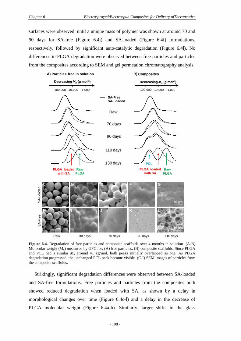
Chapter 6 Electrosprayed/Electrospun Composites for Delivery ofTherapeutics
- 198 -
surfaces were observed, until a unique mass of polymer was shown at around 70 and
90 days for SA-free (Figure 6.4j) and SA-loaded (Figure 6.4f) formulations,
respectively, followed by significant auto-catalytic degradation (Figure 6.4l). No
differences in PLGA degradation were observed between free particles and particles
from the composites according to SEM and gel permeation chromatography analysis.
Figure 6.4. Degradation of free particles and composite scaffolds over 4 months in solution. (A-B)
Molecular weight (Mn) measured by GPC for; (A) free particles, (B) composite scaffolds. Since PLGA
and PCL had a similar Mn around 41 kg/mol, both peaks initially overlapped as one. As PLGA
degradation progressed, the unchanged PCL peak became visible. (C-I) SEM images of particles from
the composite scaffolds.
Strikingly, significant degradation differences were observed between SA-loaded
and SA-free formulations. Free particles and particles from the composites both
showed reduced degradation when loaded with SA, as shown by a delay in
morphological changes over time (Figure 6.4c-l) and a delay in the decrease of
PLGA molecular weight (Figure 6.4a-b). Similarly, larger shifts in the glass
BSA-FreeBSA-Loaded
Raw
70 days
90 days
110 days
130 days
100,000 10,000 1,000
Decreasing Mn (g mol-1)
A)
PLGA loaded
with SA
Raw
PLGA
Particles free in solution
PCL
PLGA loaded
with SARaw
PLGA
Raw 30 days 70 days 90 days
SA
-Load
ed
SA
-Fre
e
C
H
B) Composites
100,000 10,000 1,000
Decreasing Mn (g mol-1)
10 µm
D E F G
I J K L
10 µm
110 days
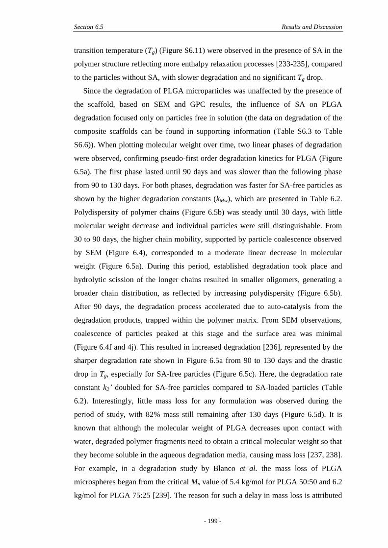
Section 6.5 Results and Discussion
- 199 -
transition temperature (Tg) (Figure S6.11) were observed in the presence of SA in the
polymer structure reflecting more enthalpy relaxation processes [233-235], compared
to the particles without SA, with slower degradation and no significant Tg drop.
Since the degradation of PLGA microparticles was unaffected by the presence of
the scaffold, based on SEM and GPC results, the influence of SA on PLGA
degradation focused only on particles free in solution (the data on degradation of the
composite scaffolds can be found in supporting information (Table S6.3 to Table
S6.6)). When plotting molecular weight over time, two linear phases of degradation
were observed, confirming pseudo-first order degradation kinetics for PLGA (Figure
6.5a). The first phase lasted until 90 days and was slower than the following phase
from 90 to 130 days. For both phases, degradation was faster for SA-free particles as
shown by the higher degradation constants (kMw), which are presented in Table 6.2.
Polydispersity of polymer chains (Figure 6.5b) was steady until 30 days, with little
molecular weight decrease and individual particles were still distinguishable. From
30 to 90 days, the higher chain mobility, supported by particle coalescence observed
by SEM (Figure 6.4), corresponded to a moderate linear decrease in molecular
weight (Figure 6.5a). During this period, established degradation took place and
hydrolytic scission of the longer chains resulted in smaller oligomers, generating a
broader chain distribution, as reflected by increasing polydispersity (Figure 6.5b).
After 90 days, the degradation process accelerated due to auto-catalysis from the
degradation products, trapped within the polymer matrix. From SEM observations,
coalescence of particles peaked at this stage and the surface area was minimal
(Figure 6.4f and 4j). This resulted in increased degradation [236], represented by the
sharper degradation rate shown in Figure 6.5a from 90 to 130 days and the drastic
drop in Tg, especially for SA-free particles (Figure 6.5c). Here, the degradation rate
constant k2’ doubled for SA-free particles compared to SA-loaded particles (Table
6.2). Interestingly, little mass loss for any formulation was observed during the
period of study, with 82% mass still remaining after 130 days (Figure 6.5d). It is
known that although the molecular weight of PLGA decreases upon contact with
water, degraded polymer fragments need to obtain a critical molecular weight so that
they become soluble in the aqueous degradation media, causing mass loss [237, 238].
For example, in a degradation study by Blanco et al. the mass loss of PLGA
microspheres began from the critical Mn value of 5.4 kg/mol for PLGA 50:50 and 6.2
kg/mol for PLGA 75:25 [239]. The reason for such a delay in mass loss is attributed
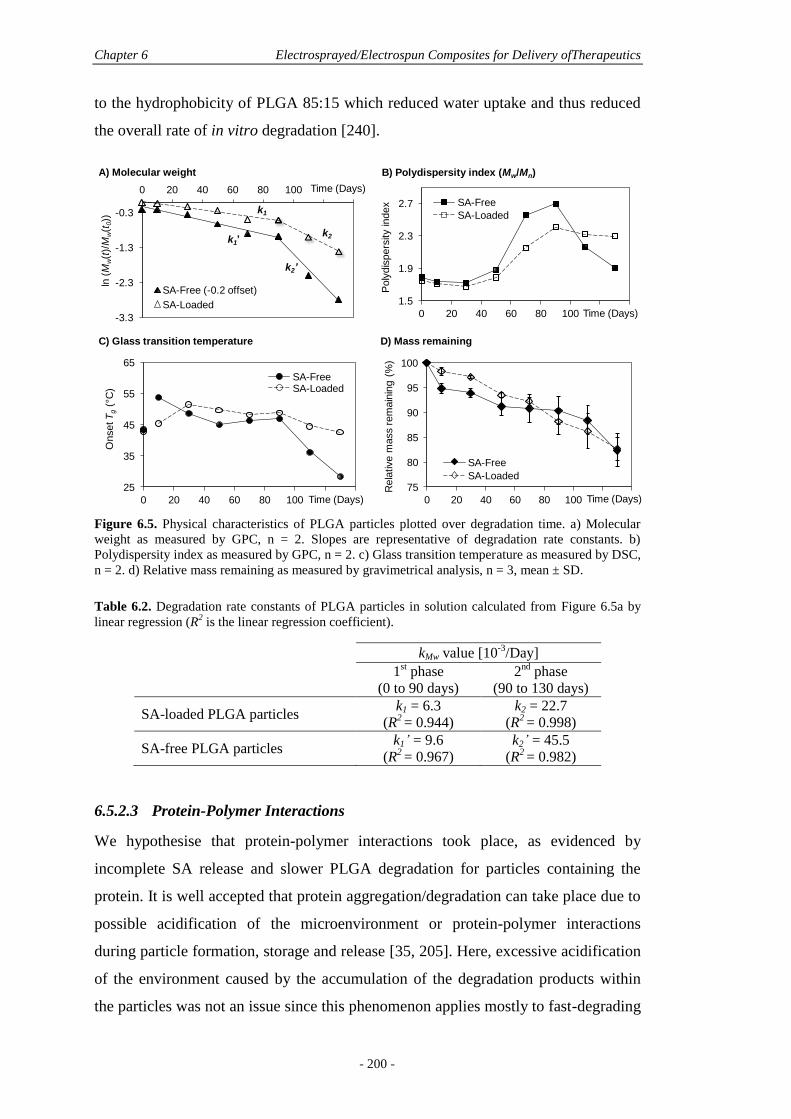
Chapter 6 Electrosprayed/Electrospun Composites for Delivery ofTherapeutics
- 200 -
to the hydrophobicity of PLGA 85:15 which reduced water uptake and thus reduced
the overall rate of in vitro degradation [240].
Figure 6.5. Physical characteristics of PLGA particles plotted over degradation time. a) Molecular
weight as measured by GPC, n = 2. Slopes are representative of degradation rate constants. b)
Polydispersity index as measured by GPC, n = 2. c) Glass transition temperature as measured by DSC,
n = 2. d) Relative mass remaining as measured by gravimetrical analysis, n = 3, mean ± SD.
Table 6.2. Degradation rate constants of PLGA particles in solution calculated from Figure 6.5a by
linear regression (R2 is the linear regression coefficient).
kMw value [10-3
/Day]
1st phase
(0 to 90 days)
2nd
phase
(90 to 130 days)
SA-loaded PLGA particles k1 = 6.3
(R2 = 0.944)
k2 = 22.7
(R2 = 0.998)
SA-free PLGA particles k1’ = 9.6
(R2 = 0.967)
k2’ = 45.5
(R2 = 0.982)
6.5.2.3 Protein-Polymer Interactions
We hypothesise that protein-polymer interactions took place, as evidenced by
incomplete SA release and slower PLGA degradation for particles containing the
protein. It is well accepted that protein aggregation/degradation can take place due to
possible acidification of the microenvironment or protein-polymer interactions
during particle formation, storage and release [35, 205]. Here, excessive acidification
of the environment caused by the accumulation of the degradation products within
the particles was not an issue since this phenomenon applies mostly to fast-degrading
75
80
85
90
95
100
0 20 40 60 80 100 120 140
Rela
tive m
ass r
em
ain
ing (
%)
SA-Free
SA-Loaded25
35
45
55
65
0 20 40 60 80 100 120 140
Onset T
g(°
C)
SA-FreeSA-Loaded
1.5
1.9
2.3
2.7
0 20 40 60 80 100 120 140
Poly
dis
pers
ity index SA-Free
SA-Loaded
-3.3
-2.3
-1.3
-0.3
0 20 40 60 80 100 120 140
ln(M
w(t
)/M
w(t
0))
SA-Free (-0.2 offset)
SA-Loaded
Time (Days)
Time (Days)
Time (Days)
A) Molecular weight
k1
k1’k2
k2’
B) Polydispersity index (Mw/Mn)
C) Glass transition temperature D) Mass remaining
Time (Days)

Section 6.5 Results and Discussion
- 201 -
PLGAs. This was not the case here, since PLGA 85:15 showed overall slow
degradation (> 5 months) and little mass loss (< 20%) so we can negate this as
contributing factor. In parallel, the monitoring of pH confirmed that pH remained at
7.4 throughout the degradation study, thus confirming the protein-polymer
interactions hypothesis.
When encapsulating proteins with methods that involve water/oil interfaces such
as multiple emulsion processes, protein degradation through non-covalent
aggregation is the main interaction taking place [241]. Alternatively, when using
electrospraying, protein-loaded particles can be produced without the use of
emulsions, by dispersing the protein directly into the organic polymer solution.
Indeed, the encapsulation efficiency of the SA-loaded PLGA particles free in
solution, measured through an extraction process involving water/oil interface was
measured as 46.4 ± 3.1%. This was lower than the total detected SA released (63.5 ±
9.9%) showing evident discrepancies (p = 0.02). This difference was attributed to the
non-covalent aggregation of SA at the water/oil interface during the encapsulation
efficiency assay. This phenomenon did not take place during electrospraying or
while the SA was released in solution, consequently a higher amount of SA may be
measured during the release study.
Boury et al. have also observed slower degradation of PLGA 50:50 in the
presence of SA and were able to show that the released SA non-specifically adsorbed
back onto the PLGA surface [242]. This resulted in a hydrophobic coating on the
surface of the polymer, hence reducing water uptake and slowing hydrolytic
degradation. This same phenomenon may be occurring on the electrosprayed
particles, although contact angle measurements were not possible owing to their size,
and we propose this phenomenon to be responsible for incomplete SA release. An
approach to limit non-specific adsorption is to use an anionic surfactant, such as
sodium dodecyl sulfate, in the release medium which can displace adsorbed albumin
from the PLGA. Crotts et al. indeed showed that up to 20% more protein were
released over eight weeks of incubation from PLGA 50:50 microparticles, compared
to when PLGA microparticles were incubated in PBS alone [210].
Overall, the protein release appears to be governed by diffusion, polymer
degradation, and protein-polymer interactions. This study emphasises the in vitro
limitations and further studies are thus required that look at the in vivo situation
Chapter 6 Electrosprayed/Electrospun Composites for Delivery ofTherapeutics
- 202 -
where different conditions, such as particle mobility, viscosity and enzymatic
participation, may trigger different behaviours.
6.5.3 Biological Effects
Here we evaluated the effect of PCL and composite scaffolds on MC3T3 precursor
osteoblast cells in vitro. MC3T3s have the potential to differentiate into osteoblasts
under osteogenic stimuli. To examine the influence of the scaffolds on cell viability
and morphology, we seeded MC3T3s onto the scaffolds and allowed them to culture
for 18 days.
The live/dead staining showed high viability and even distribution of cells across
both PCL and composite scaffolds after 1 day of culture (data not shown). After 9
and 18 days, high cell viability throughout the cell culture study showed that none of
the constructs were cytotoxic to MC3T3s (Figure 6.6a-b), and thus incorporation of
PLGA particles did not lead to reduced cell viability, an essential pre-requisite in TE
applications. Higher resolution confocal laser scanning microscopy (CLSM) (Figure
6.6c-d) and SEM images (Figure 6.7) showed a characteristic spreading morphology.
Cells attached to both fibres and particles and spanned adjacent fibres and particles.
The cells on raw PCL scaffolds exhibited a typical elongated morphology, and grew
along fibres. Interestingly, the cells on composite scaffolds showed a different
growth pattern, wrapping around the coated fibres rather than along their axes
(Figure 6.6c-d). This was likely due to the presence of particles which roughened the
topography [212]. The isotropic growth direction of cells was confirmed by SEM
where numerous filopodia of MC3T3 cells reached neighbouring particles (Figure
6.7b), while cells on the fibres alone showed preferential growth along the fibres axis
(Figure 6.7a) and across fibres at fibre crossover points (Figure 6.7d). After initial
contact with a small region on the top of neighbouring microparticles, cells then
spread around particles, covering several particles at a time, while also penetrating
between adjacent particles. Topographical features such as curvature are critical
parameters for cell locomotion. While cells prefer to extend in horizontal planes due
to limited flexibility of the cytoskeleton, they possess the ability to still make
successful protrusion and contact in any given direction [243, 244], and are more
stimulated by micropatterned surfaces than flat surfaces [212]. Importantly, here no
differences were seen between SA-loaded and SA-free composites, showing similar
cell morphology and attachment on both types of scaffold.
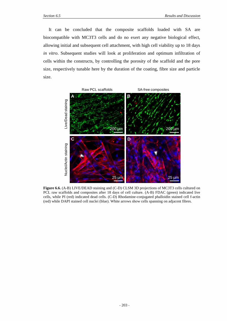
Section 6.5 Results and Discussion
- 203 -
It can be concluded that the composite scaffolds loaded with SA are
biocompatible with MC3T3 cells and do no exert any negative biological effect,
allowing initial and subsequent cell attachment, with high cell viability up to 18 days
in vitro. Subsequent studies will look at proliferation and optimum infiltration of
cells within the constructs, by controlling the porosity of the scaffold and the pore
size, respectively tunable here by the duration of the coating, fibre size and particle
size.
Figure 6.6. (A-B) LIVE/DEAD staining and (C-D) CLSM 3D projections of MC3T3 cells cultured on
PCL raw scaffolds and composites after 18 days of cell culture. (A-B) FDAC (green) indicated live
cells, while PI (red) indicated dead cells. (C-D) Rhodamine-conjugated phalloidin stained cell f-actin
(red) while DAPI stained cell nuclei (blue). White arrows show cells spanning on adjacent fibres.
200 µm
Raw PCL scaffolds SA-free composites
Liv
e/D
ea
d s
tain
ing
Nu
cle
i/A
ctin
sta
inin
g
200 µm
25 µm 25 µm
A B
C D
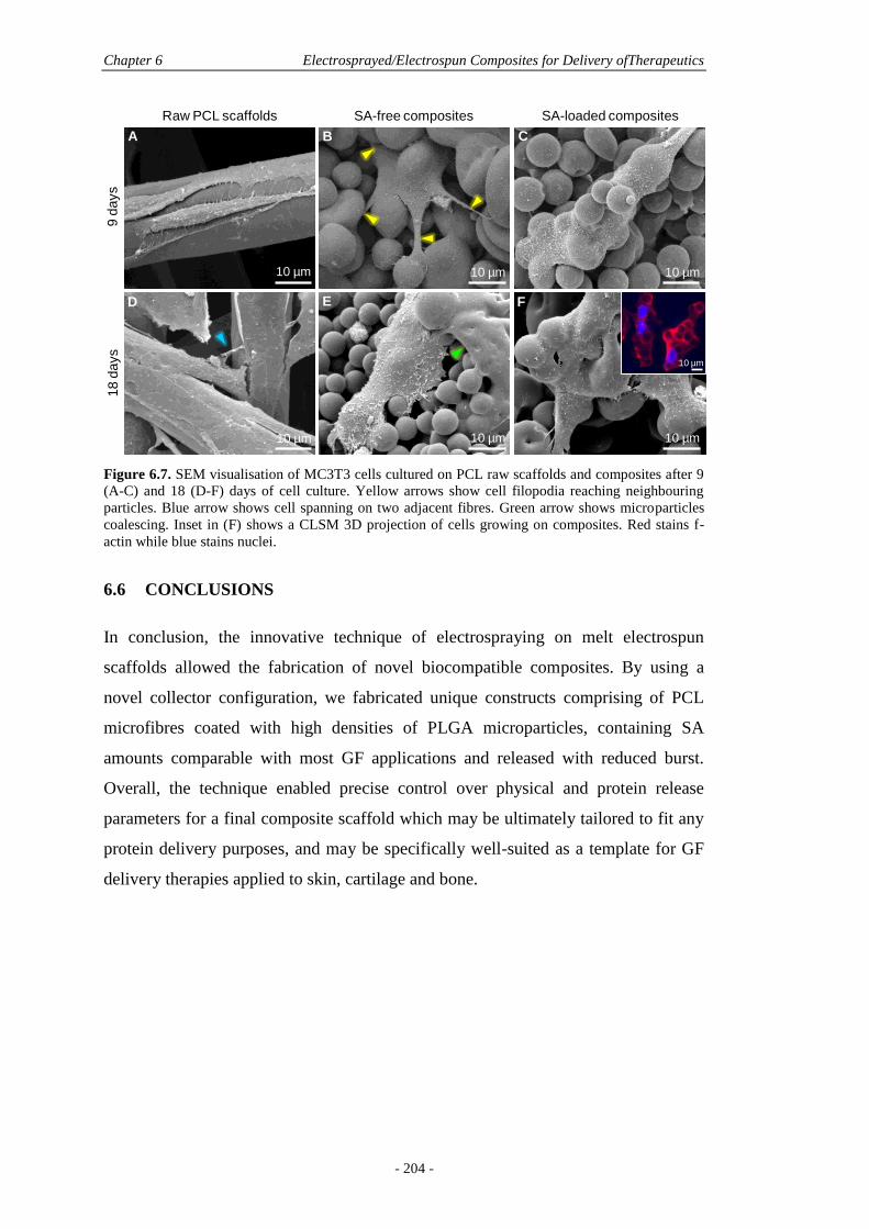
Chapter 6 Electrosprayed/Electrospun Composites for Delivery ofTherapeutics
- 204 -
Figure 6.7. SEM visualisation of MC3T3 cells cultured on PCL raw scaffolds and composites after 9
(A-C) and 18 (D-F) days of cell culture. Yellow arrows show cell filopodia reaching neighbouring
particles. Blue arrow shows cell spanning on two adjacent fibres. Green arrow shows microparticles
coalescing. Inset in (F) shows a CLSM 3D projection of cells growing on composites. Red stains f-
actin while blue stains nuclei.
6.6 CONCLUSIONS
In conclusion, the innovative technique of electrospraying on melt electrospun
scaffolds allowed the fabrication of novel biocompatible composites. By using a
novel collector configuration, we fabricated unique constructs comprising of PCL
microfibres coated with high densities of PLGA microparticles, containing SA
amounts comparable with most GF applications and released with reduced burst.
Overall, the technique enabled precise control over physical and protein release
parameters for a final composite scaffold which may be ultimately tailored to fit any
protein delivery purposes, and may be specifically well-suited as a template for GF
delivery therapies applied to skin, cartilage and bone.
10 µm
F
Raw PCL scaffolds SA-free composites SA-loaded composites9
days
18
da
ys
10 µm 10 µm 10 µm
10 µm 10 µm
A B C
D E
10 µm
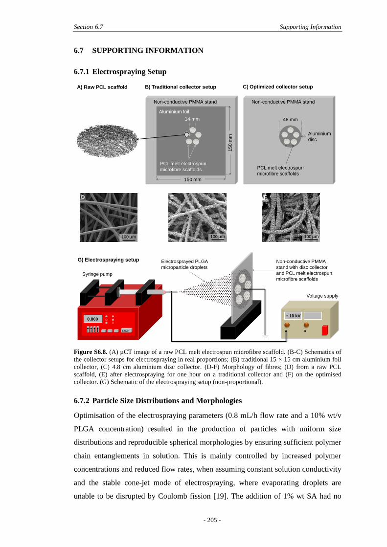
Section 6.7 Supporting Information
- 205 -
6.7 SUPPORTING INFORMATION
6.7.1 Electrospraying Setup
Figure S6.8. (A) µCT image of a raw PCL melt electrospun microfibre scaffold. (B-C) Schematics of
the collector setups for electrospraying in real proportions; (B) traditional 15 × 15 cm aluminium foil
collector, (C) 4.8 cm aluminium disc collector. (D-F) Morphology of fibres; (D) from a raw PCL
scaffold, (E) after electrospraying for one hour on a traditional collector and (F) on the optimised
collector. (G) Schematic of the electrospraying setup (non-proportional).
6.7.2 Particle Size Distributions and Morphologies
Optimisation of the electrospraying parameters (0.8 mL/h flow rate and a 10% wt/v
PLGA concentration) resulted in the production of particles with uniform size
distributions and reproducible spherical morphologies by ensuring sufficient polymer
chain entanglements in solution. This is mainly controlled by increased polymer
concentrations and reduced flow rates, when assuming constant solution conductivity
and the stable cone-jet mode of electrospraying, where evaporating droplets are
unable to be disrupted by Coulomb fission [19]. The addition of 1% wt SA had no
100 µm 100 µm
B) Traditional collector setup
0.800
START
+ 10 kV
G) Electrospraying setup
Syringe pump
Voltage supply
Non-conductive PMMA
stand with disc collector
and PCL melt electrospun
microfibre scaffolds
Electrosprayed PLGA
microparticle droplets
Aluminium
disc
48 mm
Non-conductive PMMA stand
PCL melt electrospun
microfibre scaffolds
Non-conductive PMMA stand
PCL melt electrospun
microfibre scaffolds
14 mm
150 mm
15
0 m
m
Aluminium foil
C) Optimized collector setupA) Raw PCL scaffold
100 µm
D E F

Chapter 6 Electrosprayed/Electrospun Composites for Delivery ofTherapeutics
- 206 -
discernible effect on the morphology of particles and was similar to SA-free
particles. Morphology of particles collected either on the collector or coated on the
fibres were identical, also no change was observed when moving to the new collector
configuration, either with or without the addition of SA, confirming the
electrospraying processing parameters and configuration chosen here as highly
homogenous.
Figure S6.9. (A) Comparison of particle size distributions of SA-loaded and SA-free particles within
scaffolds (µm). (B) Comparison of particle size distributions of SA-free particles collected on the
collector and SA-free particles embedded within the scaffolds (µm). (C-D) SEM images of SA-free
particles found; (C) within scaffolds and; (D) collected from the aluminium disc. The wider size
distribution for particles collected on the aluminium foil is due to the presence of smaller satellite
particles at the periphery of the cone formed when particles divide en route to the collector.
Conversely, the scaffolds were placed more centrally on the collector and as such deposition of
satellite particles was minimised.
0.0
0.1
0.2
0.3
0.4
0.5
0.6
1.0 2.3 3.7 5.0 6.3 7.7 9.0
Fra
ctio
n o
f p
op
ula
tio
n
Particle diameter (µm)
BSA-free particles: From the collector
BSA-free particles: Embedded within scaffolds
0.0
0.1
0.2
0.3
0.4
0.5
0.6
0.7
0.8
1.0 3.0 5.0 7.0 9.0 11.0 13.0Fra
ctio
n o
f p
op
ula
tio
n
Particle diameter (µm)
Within scaffolds: BSA-loaded particlesWithin scaffolds: BSA-free particles
A B
C D
10 µm 10 µm
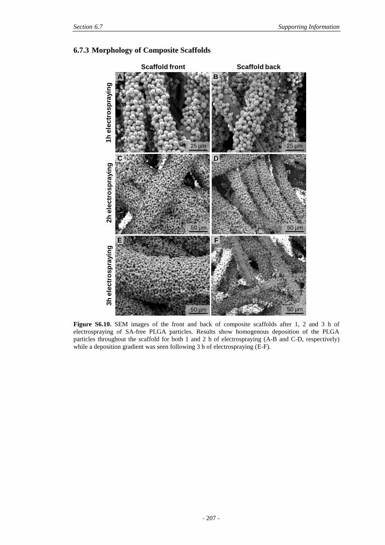
Section 6.7 Supporting Information
- 207 -
6.7.3 Morphology of Composite Scaffolds
Figure S6.10. SEM images of the front and back of composite scaffolds after 1, 2 and 3 h of
electrospraying of SA-free PLGA particles. Results show homogenous deposition of the PLGA
particles throughout the scaffold for both 1 and 2 h of electrospraying (A-B and C-D, respectively)
while a deposition gradient was seen following 3 h of electrospraying (E-F).
50 µm
25 µm
50 µm
50 µm 50 µm
25 µm
Scaffold front Scaffold back
1h
ele
ctr
osp
rayin
g2h
ele
ctr
osp
rayin
g3h
ele
ctr
osp
rayin
g
A B
C D
E F
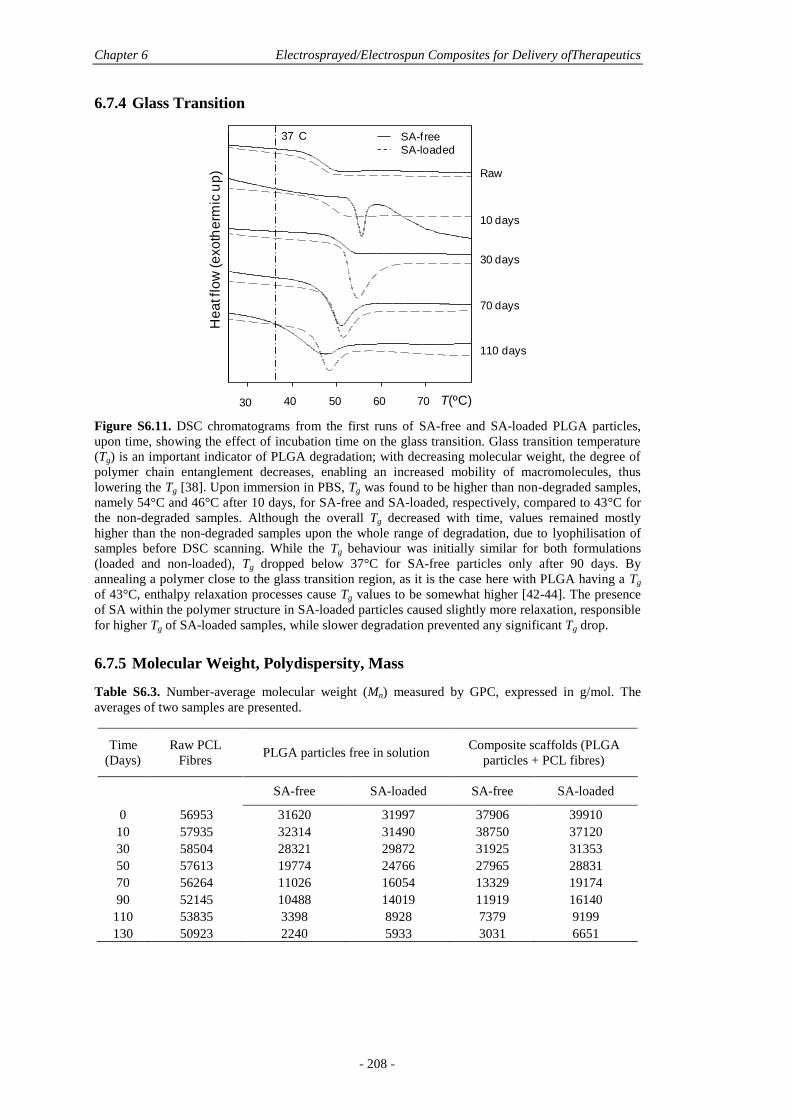
Chapter 6 Electrosprayed/Electrospun Composites for Delivery ofTherapeutics
- 208 -
6.7.4 Glass Transition
Figure S6.11. DSC chromatograms from the first runs of SA-free and SA-loaded PLGA particles,
upon time, showing the effect of incubation time on the glass transition. Glass transition temperature
(Tg) is an important indicator of PLGA degradation; with decreasing molecular weight, the degree of
polymer chain entanglement decreases, enabling an increased mobility of macromolecules, thus
lowering the Tg [38]. Upon immersion in PBS, Tg was found to be higher than non-degraded samples,
namely 54°C and 46°C after 10 days, for SA-free and SA-loaded, respectively, compared to 43°C for
the non-degraded samples. Although the overall Tg decreased with time, values remained mostly
higher than the non-degraded samples upon the whole range of degradation, due to lyophilisation of
samples before DSC scanning. While the Tg behaviour was initially similar for both formulations
(loaded and non-loaded), Tg dropped below 37°C for SA-free particles only after 90 days. By
annealing a polymer close to the glass transition region, as it is the case here with PLGA having a Tg
of 43°C, enthalpy relaxation processes cause Tg values to be somewhat higher [42-44]. The presence
of SA within the polymer structure in SA-loaded particles caused slightly more relaxation, responsible
for higher Tg of SA-loaded samples, while slower degradation prevented any significant Tg drop.
6.7.5 Molecular Weight, Polydispersity, Mass
Table S6.3. Number-average molecular weight (Mn) measured by GPC, expressed in g/mol. The
averages of two samples are presented.
Time
(Days)
Raw PCL
Fibres PLGA particles free in solution
Composite scaffolds (PLGA
particles + PCL fibres)
SA-free SA-loaded SA-free SA-loaded
0 56953 31620 31997 37906 39910
10 57935 32314 31490 38750 37120
30 58504 28321 29872 31925 31353
50 57613 19774 24766 27965 28831
70 56264 11026 16054 13329 19174
90 52145 10488 14019 11919 16140
110 53835 3398 8928 7379 9199
130 50923 2240 5933 3031 6651
Raw
10 days
30 days
70 days
110 days
He
at f
low
(e
xo
the
rmic
up
)
-3.5
-2.5
-1.5
-0.5
Hea
t Flo
w (W
/g)
25 45 65 85 105 125 145 165
Temperature (°C)Exo Up Universal V4.5A TA Instruments
30 40 50 60 70 T(ºC)
SA-freeSA-loaded
37 C

Section 6.7 Supporting Information
- 209 -
Table S6.4. Weight-average molecular weight (Mw) measured by GPC, expressed in g/mol. The
averages of two samples are presented.
Time
(Days)
Raw PCL
Fibres PLGA particles free in solution
Composite scaffolds (PLGA
particles + PCL fibres)
SA-free SA-loaded SA-free SA-loaded
0 80315 56570 55940 61600 63649
10 81652 56121 53979 62587 60905
30 81579 48682 50070 55425 55427
50 81867 37131 44333 51487 53731
70 82755 28119 34082 45434 50450
90 81089 26340 33739 41169 48631
110 80883 8535 20676 38369 39665
130 79950 4271 13628 32394 38075
Table S6.5. Polydispersity index, representative of Mw/Mn, measured by GPC. The averages of two
samples are presented.
Time
(Days)
Raw PCL
Fibres PLGA particles free in solution
Composite scaffolds (PLGA
particles + PCL fibres)
SA-free SA-loaded SA-free SA-loaded
0 1.41 1.59 1.59 1.79 1.75
10 1.41 1.64 1.64 1.74 1.71
30 1.39 1.74 1.77 1.72 1.68
50 1.42 1.84 1.86 1.88 1.79
70 1.47 3.41 2.63 2.56 2.15
90 1.57 3.49 3.01 2.69 2.41
110 1.50 5.20 4.33 2.17 2.32
130 1.57 10.69 5.73 1.90 2.30
Table S6.6. Average mass remaining (%) measured by gravimetrical analysis. The averages of three
samples are presented.
Time (Days)
0 10 30 50 70 90 110 130
Raw PCL fibres
100 100 100 100 100 100 100 100
PLGA particles free in
solution
SA-free 100 94.8 93.9 91.2 90.8 90.3 88.4 82.4
SA-loaded 100 98.3 97.1 93.5 92.3 88.2 86.2 82.6
Composite scaffolds (PLGA
particles + PCL fibres)
SA-free 100 95.3 96.3 94.1 93.4 92.9 92.3 89.0
SA-loaded 100 97.8 97.3 95.2 93.6 93.8 92.7 90.3
Chapter 6 Electrosprayed/Electrospun Composites for Delivery ofTherapeutics
- 210 -
6.8 ACKNOWLEDGEMENTS
The authors would like to thank Dr. Rachel Hancock (QUT) for biological sample
preparation for SEM analysis. N.B. acknowledges the financial support from QUT in
the form of an Australian Postgraduate Award scholarship, and top-up from the
Deputy Vice Chancellor. B.F. acknowledges support from the Wound Management
Innovation CRC. This work was supported by the Australian Research Council
(Linkage grant LP110200082).

- 211 -
Chapter 7: Summary and Future Directions
Here, the outcomes of this thesis are discussed, with respect to the research problem
and aims stated in Chapter 1. It was hypothesised that the electrospraying
technology may be used to produce biodegradable microparticles encapsulating and
delivering growth factors (GFs) relevant in bone tissue engineering.
The aims addressing this research problem were; to understand and tailor the
processing parameters involved in electrosprayed particle formation, to develop
electrosprayed particle formulations for reproducible and efficient GF encapsulation,
to characterise GF-loaded formulations for in vitro release and bioactivity, and to
investigate the potential of loaded electrosprayed microparticles used in association
with a porous fibre scaffold in vitro, as a suitable construct for tissue engineering.
Development of electrosprayed particles containing growth factors
A review of the literature (Chapter 2) collates and summarises the current body of
research surrounding the use of the electrospraying technique applied to the loading
of therapeutic molecules for delivery from biodegradable polymeric particles. The
chapter suggests that electrospraying is a promising technology for drug delivery
applications, yet is scarcely used and characterised for the encapsulation of proteins
and GFs for applications in tissue engineering.
A key to reproducible electrospraying is the understanding of the complex
interplay between materials and electrospraying processing parameters (Chapter 3
and 4), which direct the size distributions and morphology of particles – two
essential parameters to efficiently encapsulate and deliver GFs. Electrospraying
requires a strict control over processing parameters which are inter-dependently
linked (Chapter 3). The polymer entanglement regime taking place in the course of
the electrospraying process is essential to reproducible, spherical and narrowly
distributed particles, otherwise leading to shapeless particles, fibres, and
offspring/secondary droplets, responsible for irreproducible morphologies and
bimodal size distributions. The two strongest parameters to control the entanglement
regime are electrospraying flow rate and polymer concentration whereas less
significant variables include tip-to-collector distance, voltage and needle gauge. For
Chapter 7 Summary and Future Directions
- 212 -
a standard FDA-approved biodegradable polymer, such as polycaprolactone (PCL)
(84 kDa) dissolved in chloroform, the optimum conditions involve a 9-10% wt/v
concentration and flow rates above 0.5 mL/h, generating average particle sizes
between 10 and 20 µm.
While a single polymer/solvent combination is more easily optimisable, the
blending with an additional polymer can create instabilities during the
electrospraying process, influencing the polymer entanglements and final
characteristics of particles (Chapter 4). When PCL and poly(lactic-co-glycolic acid)
(PLGA) are mixed with 10% wt of poly(ethylene glycol) (PEG), a spread of particle
sizes and morphologies are obtained. Here, flow rate and concentration, along with
molecular weight of the additive are important variables to control in order to obtain
spherical and monodisperse particles. However, not all combinations are able to
provide sufficiently large particle sizes, which are required for homogeneous, dry
encapsulation of large GF clusters. PEG is an efficient protective agent for proteins
and GFs (Chapter 5) and good microniser (Chapter 4) prior to dry encapsulation in
electrosprayed particles, yet encapsulation of a model protein, serum albumin (SA),
is improved for increasing particle sizes. In general, higher molecular weight PEG,
close to the molecular weight of the matrix polymer and higher electrospraying flow
rates (here up to 3 mL/h) should be considered, for increased particle sizes. An
increase in flow rate, however, correlates with bimodal size distributions being
generated, comprising 50% of primary and 50% secondary droplets (which are
approximately half the size of the primary droplets).
Compared to the amount and molecular weight of PEG used here, particle size
distributions are more determinant in influencing the release profiles of SA, with
broader distributions generating more particle aggregation in solution. Aggregation
reduces burst release, providing more sustained but less overall release of the protein
during the diffusion stage of release. Hence, to avoid bimodal size distributions, flow
rates need to be reduced, in turn also lowering the final average particle size. When
applied to an FDA-approved polymer such as PLGA 85:15, which presents a
degradation profile more suited to GF delivery applications than PCL due to a faster
degradation, optimised parameters for GF encapsulation are obtained using a
polymer concentration of 11% wt/v and a flow rate of 0.8 mL/h (Chapter 5). This
generates quasi-monodisperse particles of around 6 µm in size, which allows
Chapter 7 Summary and Future Directions
- 213 -
reproducible and efficient encapsulation of dry bone morphogenetic protein 7 (BMP-
7) and vascular endothelial GF (VEGF), following micronisation with PEG.
Characterisation of growth factors in vitro
The in vitro characterisation of a drug release system is helpful in understanding
performance in vivo, and is a pre-requisite to any expensive and complex experiment.
Here, a challenge lies in detecting protein drugs encapsulated and released from
polymeric electrosprayed particles in vitro, due to significant interactions with the
environment (Chapter 4, 5, 6). Due to the presence of hydrophobic domains in
proteins and growth factors, they tend to aggregate together and non-specifically
adsorb to the polymer matrix, which is hydrophobic in nature. This can happen at
several stages of processing, from micronisation up until delivery, but also during
post-encapsulation quantification.
An important finding here is that in the course of GF processing, especially
involving drying after contact with organic and aqueous solvents, a significant
degree of aggregation between GFs takes place. GF dissociation is not fully achieved
by re-dissolution in an aqueous solvent, as evidenced by lower GF concentrations in
solution measured by the enzyme-linked immunosorbent assay (ELISA) assay.
Strikingly, these processed GFs present a full bioactivity when placed in contact with
cells (Chapter 5). This result indicates that the nature of aggregation obtained
through processing relative to electrospraying, is non-covalent and does not affect
protein stability.
During characterisation of GFs in vitro, non-covalent aggregation is accompanied
by a degree of non-specific adsorption to the hydrophobic polymer matrix, which the
electrosprayed particles are made of. This is shown to lower GF detection but also
affect particle degradation during in vitro release, which in turn may alter the release
profiles (Chapter 6). This generates complications in characterisation; a strategy to
overcome this involves the use of surfactants. Here, Tween 20® and sodium dodecyl
sulphate (SDS) are efficient in displacing adsorbed growth factors from hydrophobic
matrices to some extent. However, they are unable to fully dissociate aggregated
proteins, as seen with SA (Chapter 4), and growth factors, such as VEGF and BMP-
7 (Chapter 5).
Chapter 7 Summary and Future Directions
- 214 -
Assessing the encapsulation efficiency by extraction procedures, which involve
the dissolution of loaded electrosprayed particles in an organic solvent, is mostly
affected by GF aggregation, generating results lower than 50%, sometimes lower
than the total amounts detected during release assays, as measured by ELISA. The in
vitro release profiles of SA, VEGF and BMP-7 are highly dependent on the in vitro
conditions rather than particle formulations, involving the amount of particles studied
and the presence of surfactant in solution. Non-specific adsorption to polymer is
dominant during release and is better counterbalanced by the use of SDS, an anionic
surfactant, than Tween 20®, a non-ionic surfactant (Chapter 5). All profiles are
affected by incomplete release due to GF interactions with their environment, which
the presence of surfactant in solution but also the presence of PEG, SA, and trehalose
in the particle formulation do not fully impair. Trehalose, in particular (1% wt of the
particle formulation), leads to reduced burst release of BMP-7 from electrosprayed
particles, but also reduces overall release due to promotion of BMP-7 aggregates
during the micronisation step which further reduces detection in solution, as
measured by ELISA. Conversely, similar bioactivity is measured in vitro on pre-
osteoblasts when either the formulation with or without the trehalose is used,
showing the discrepancies of release assays in PBS and measured by ELISA, and the
actual effectiveness seen with direct contact with cells.
Here it becomes clear that in vitro assays may be limited in truly assessing
electrosprayed particles loaded and releasing GFs. An in vivo experiment may be
more suitable, whereby the environment offers further possible interactions and is the
only environment whereby the GF action can be truly measured via assessing the
new tissue formation/regeneration. This could be, for instance, assessed by an
ectopic bone model in mice.
Potential of electrospraying for tissue engineering
In order to validate electrosprayed particles loaded with GFs to be used for
applications in tissue engineering, particles must be non-toxic and minimise potential
GF denaturation during processing. The electrospraying process indeed requires
organic solvents that come in contact with GFs, which may be a potential source of
GF denaturation and toxicity for tissue engineering applications. Here, GF-free PCL
electrosprayed microparticles have no adverse effects on fibroblast cells up to 48 h
Chapter 7 Summary and Future Directions
- 215 -
after direct exposure (Chapter 3), inferring that the organic solvent is fully removed
following the electrospraying process.
Next, when BMP-7 and VEGF are freeze-dried, micronised with PEG, and
vortexed with the organic solvent, which are the most critical steps during the
electrospraying process, it is shown that both GFs perform in an unaltered manner in
vitro in contact with cells (Chapter 5). When microparticles loaded with BMP-7 are
placed in vitro in direct contact with pre-osteoblasts, significant cell differentiation is
observed up to three weeks due to active BMP-7 being released from microparticles,
hence validating the technique for the specific bone tissue engineering application.
The electrospraying process is an atomization process, the final particles produced
are dry and do not need extra treatment after production. Due to the nature of the
fabrication method, particles are also delivered with a natural homogenous
distribution on a collector. This is a great advantage for applications in tissue
engineering, where scaffolds and other matrices can homogeneously be coated with
particles, when placed under the electrospraying cone (Chapter 6). Here, PCL melt
electrospun meshes provide a suitable substrate with high porosity and pore size
allowing scaffold coating throughout the structure. Interestingly, due to the
immobilisation of PLGA particles on the surface of the meshes, burst release of SA
is reduced, compared to particles free in solution. As seen with particle size
distributions (Chapter 4), particle aggregation is, again, paramount in tailoring the
release profiles of GF from electrosprayed particles. In terms of suitability of the
electrosprayed/electrospun composites developed here, they have a positive effect in
contact with precursor osteoblast cells up to 18 days in culture, which is an
encouraging result for further consideration as a construct for bone tissue
engineering.
Future Directions
In this thesis, the potential of the electrospraying technology for producing
biodegradable microparticles encapsulating and delivering growth factors relevant in
bone tissue engineering, namely VEGF and BMP-7, is discussed. While positive
results lean towards this goal with the use of simple polyester polymers such as
PLGA and PCL, several areas still need to be addressed. Particle size distributions
and particle configuration, involving aggregation in solution or immobilisation on a
Chapter 7 Summary and Future Directions
- 216 -
scaffold, seem to be key in directing the release of GFs from electrosprayed particles
and may be an important variable to contend with for the tissue engineering
application. Importantly, these parameters seem more dominant over the actual
particle formulation, with the additives and amounts studied here (10% wt PEG and
1% wt trehalose). GF interactions are a significant issue in the in vitro
characterisation of electrosprayed particles loaded with VEGF and BMP-7, and may
be similar for any type of GF. The optimisation of the in vitro environment is
essential to achieve accurate quantification but may actually be difficult to achieve,
which here becomes a strong argument in favour of in vivo assessment instead,
although this remains controversial with increased costs.
While burst release is often regarded negatively in the field of drug delivery in
general, it is not the specific case of GF delivery, where burst delivery is as
beneficial and necessary as sustained delivery. Indeed, a complex cascade of
numerous growth factors need to occur to allow full tissue reconstruction and the
burst release of specific growth factors during this process is also essential, for
instance in triggering the recruitment of natural growth factors. Hence, in the field of
GF delivery, burst release should be regarded as complementary to sustained
delivery and rather than avoiding it, a thorough control and tailoring of all types of
profiles (burst and sustained) would be more useful.
Finally, the use of electrospraying with GFs on fibre scaffolds is established as a
successful solution for turning inert fibres into tissue-inductive materials, but will
require more characterisation to be fully translated to the bone tissue engineering
application. More specifically, the possibility of simultaneously electrospraying and
electrospinning the scaffold material should provide an ideal construct with more
tailoring possibilities for wider applications in the biomedical field.
- 217 -
Bibliography
[1] Williams, D. F., The Williams Dictionary of Biomaterials. Liverpool
University Press: 1999.
[2] MacNeil, S., Progress and opportunities for tissue-engineered skin. Nature
2007, 445, 874-880.
[3] Langer, R.; Vacanti, J. P., Tissue Engineering. Science 1993, 260, 920-926.
[4] Hutmacher, D. W.; Garcia, A. J., Scaffold-based bone engineering by using
genetically modified cells. Gene 2005, 347, 1-10.
[5] Whitaker, M. J.; Quirk, R. A.; Howdle, S. M.; Shakesheff, K. M., Growth
factor release from tissue engineering scaffolds. J. Pharm. Pharmacol. 2001,
53, 1427-1437.
[6] Babensee, J. E.; McIntire, L. V.; Mikos, A. G., Growth factor delivery for
tissue engineering. Pharm. Res. 2000, 17, 497-504.
[7] Chen, R. R.; Mooney, D. J., Polymeric growth factor delivery strategies for
tissue engineering. Pharm. Res. 2003, 20, 1103-1112.
[8] Nagai, M. K.; Embil, J. M., Becaplermin: recombinant platelet derived
growth factor, a new treatment for healing diabetic foot ulcers. Exp. Op.
Biolog. Ther. 2002, 2, 211-218.
[9] Cahill, K. S.; Chi, J. H.; Day, A.; Claus, E. B., Prevalence, Complications,
and Hospital Charges Associated With Use of Bone-Morphogenetic Proteins
in Spinal Fusion Procedures. JAMA 2009, 302, 58-66.
[10] Lysaght, M. J.; Jaklenec, A.; Deweerd, E., Great expectations: Private sector
activity in tissue engineering, regenerative medicine, and stem cell
therapeutics. Tissue Eng. A 2008, 14, 305-357.
[11] Place, E. S.; Evans, N. D.; Stevens, M. M., Complexity in biomaterials for
tissue engineering. Nat. Mater. 2009, 8, 457-470.
[12] Bessa, P. C.; Casal, M.; Reis, R. L., Bone morphogenetic proteins in tissue
engineering: the road from the laboratory to the clinic, part I (basic
concepts). J. Tissue Eng. Regen. M. 2008, 2, 1-13.
[13] Kang, J. D., Commentary: Another complication associated with rhBMP-2?
Spine J. 2011, 11, 517-519.
[14] Carragee, E. J.; Hurwitz, E. L.; Weiner, B. K., A critical review of
recombinant human bone morphogenetic protein-2 trials in spinal surgery:
emerging safety concerns and lessons learned. Spine J. 2011, 11, 471-491.
[15] Mannion, R. J.; Nowitzke, A. M.; Wood, M. J., Promoting fusion in
minimally invasive lumbar interbody stabilization with low-dose bone
morphogenic protein-2-but what is the cost? Spine J. 2011, 11, 527-533.
[16] Vasita, R.; Katti, D. S., Growth factor-delivery systems for tissue
engineering: a materials perspective. Expert Rev. Med. Dev. 2006, 3, 29-47.
[17] Sokolsky-Papkov, M.; Agashi, K.; Olaye, A.; Shakesheff, K.; Domb, A. J.,
Polymer carriers for drug delivery in tissue engineering. Adv. Drug Deliver.
Rev. 2007, 59, 187-206.
[18] Freiberg, S.; Zhu, X., Polymer microspheres for controlled drug release. Int.
J. Pharm. 2004, 282, 1-18.
- 218 -
[19] Smith, L. A.; Liu, X. H.; Ma, P. X., Tissue engineering with nano-fibrous
scaffolds. Soft Matter 2008, 4, 2144-2149.
[20] Szentivanyi, A.; Chakradeo, T.; Zernetsch, H.; Glasmacher, B., Electrospun
cellular microenvironments: Understanding controlled release and scaffold
structure. Adv. Drug Deliver. Rev. 2011, 63, 209-220.
[21] Venugopal, J.; Low, S.; Choon, A. T.; Ramakrishna, S., Interaction of cells
and nanofiber scaffolds in tissue engineering. J. Biomed. Mater. Res. B 2008,
84B, 34-48.
[22] Chung, H. J.; Park, T. G., Surface engineered and drug releasing pre-
fabricated scaffolds for tissue engineering. Adv. Drug Deliver. Rev. 2007,
59, 249-262.
[23] Hadjiargyrou, M.; Chiu, J. B., Enhanced composite electrospun nanofiber
scaffolds for use in drug delivery. Exp. Op. Drug Deliv. 2008, 5, 1093-1106.
[24] Tessmar, J. K.; Goepferich, A. M., Matrices and scaffolds for protein
delivery in tissue engineering. Adv. Drug Deliver. Rev. 2007, 59, 274-291.
[25] Chew, S. Y.; Wen, J.; Yim, E. K. F.; Leong, K. W., Sustained Release of
Proteins from Electrospun Biodegradable Fibers. Biomacromolecules 2005,
6, 2017-2024.
[26] Freitas, S.; Merkle, H. P.; Gander, B., Microencapsulation by solvent
extraction/evaporation: reviewing the state of the art of microsphere
preparation process technology. J. Control. Release 2005, 102, 313-332.
[27] Jaworek, A.; Sobczyk, A. T., Electrospraying route to nanotechnology: An
overview. J. Electrostat. 2008, 66, 197-219.
[28] Jaworek, A., Electrostatic micro- and nanoencapsulation and
electroemulsification: A brief review. J. Microencapsul. 2008, 25, 443-468.
[29] Wang, F.; Li, Z. Q.; Tamama, K.; Sen, C. K.; Guan, J. J., Fabrication and
Characterization of Prosurvival Growth Factor Releasing, Anisotropic
Scaffolds for Enhanced Mesenchymal Stem Cell Survival/Growth and
Orientation. Biomacromolecules 2009, 10, 2609-2618.
[30] Ekaputra, A. K.; Prestwich, G. D.; Cool, S. M.; Hutmacher, D. W., The three-
dimensional vascularization of growth factor-releasing hybrid scaffold of
poly (ɛ-caprolactone)/collagen fibers and hyaluronic acid hydrogel.
Biomaterials 2011, 32, 8108-8117.
[31] Sukarto, A.; Amsden, B. G., Low melting point amphiphilic microspheres for
delivery of bone morphogenetic protein-6 and transforming growth factor-β3
in a hydrogel matrix. J. Control. Release 2012, 158, 53-62.
[32] Sukarto, A.; Yu, C.; Flynn, L. E.; Amsden, B. G., Co-delivery of Adipose-
Derived Stem Cells and Growth Factor-Loaded Microspheres in RGD-
Grafted N-Methacrylate Glycol Chitosan Gels for Focal Chondral Repair.
Biomacromolecules 2012, 13, 2490-2502.
[33] Soran, Z.; Aydin, R. S. T.; Gumusderelioglu, M., Chitosan scaffolds with
BMP-6 loaded alginate microspheres for periodontal tissue engineering. J.
Microencapsul. 2012, 29, 770-780.
[34] Putney, S. D.; Burke, P. A., Improving protein therapeutics with sustained-
release formulations. Nat. Biotechnol. 1998, 16, 153-157.
[35] Ye, M.; Kim, S.; Park, K., Issues in long-term protein delivery using
biodegradable microparticles. J. Control. Release 2010, 146, 241-260.
[36] Chen, F.-M.; Zhang, M.; Wu, Z.-F., Toward delivery of multiple growth
factors in tissue engineering. Biomaterials 2010, 31, 6279-6308.
- 219 -
[37] Li, H. F.; Zhang, H. M.; Guo, X. L., Preparation of Micro-/Nano-
Nonspherical Polymer Particles. Prog. Chem. 2011, 23, 1196-1210.
[38] Chan, H.-K.; Kwok, P. C. L., Production methods for nanodrug particles
using the bottom-up approach. Adv. Drug Deliver. Rev. 2011, 63, 406-416.
[39] Peltonen, L.; Valo, H.; Kolakovic, R.; Laaksonen, T.; Hirvonen, J.,
Electrospraying, spray drying and related techniques for production and
formulation of drug nanoparticles. Exp. Op. Drug Deliv. 2010, 7, 705-719.
[40] Lassalle, V.; Ferreira, M. L., PLA nano- and microparticles for drug delivery:
An overview of the methods of preparation. Macromol. Biosci. 2007, 7, 767-
783.
[41] Ciach, T., Application of electro-hydro-dynamic atomization in drug delivery.
J. Drug. Deliv. Sci. Tech. 2007, 17, 367-375.
[42] Hartman, R. P. A.; Brunner, D. J.; Camelot, D. M. A.; Marijnissen, J. C. M.;
Scarlett, B., Jet break-up in electrohydrodynamic atomization in the cone-jet
mode. J. Aerosol Sci. 2000, 31, 65-95.
[43] Brandenberger, H.; Nussli, D.; Piech, V.; Widmer, F., Monodisperse particle
production: A method to prevent drop coalescence using electrostatic forces.
J. Electrostat. 1999, 45, 227-238.
[44] Gomez, A.; Bingham, D.; Juan, L. d.; Tang, K., Production of protein
nanoparticles by electrospray drying. J. Aerosol Sci. 1998, 29, 561-574.
[45] Yue, H.; Wei, W.; Yue, Z.; Lv, P.; Wang, L.; Ma, G.; Su, Z., Particle size
affects the cellular response in macrophages. Eur. J. Pharm. Sci. 2010, 41,
650-657.
[46] Xie, Y. B.; Castracane, J., High-Voltage, Electric Field-Driven
Micro/Nanofabrication for Polymeric Drug Delivery Systems Electrostatic
Techniques and Biomedical Application. IEEE Eng. Med. Biol. Mag. 2009,
28, 23-30.
[47] Amsden, B. G.; Goosen, M. F. A., An examination of factors affecting the
size, distribution and release characteristics of polymer microbeads made
using electrostatics. J. Control. Release 1997, 43, 183-196.
[48] Chakraborty, S.; Liao, I. C.; Adler, A.; Leong, K. W., Electrohydrodynamics:
A facile technique to fabricate drug delivery systems. Adv. Drug Deliver.
Rev. 2009, 61, 1043-1054.
[49] Almeria, B.; Deng, W. W.; Fahmy, T. M.; Gomez, A., Controlling the
morphology of electrospray-generated PLGA microparticles for drug
delivery. J. Colloid Interf. Sci. 2010, 343, 125-133.
[50] Almería, B.; Fahmy, T. M.; Gomez, A., A multiplexed electrospray process
for single-step synthesis of stabilized polymer particles for drug delivery. J.
Control. Release 2011, 154, 203-210.
[51] Arya, N.; Chakraborty, S.; Dube, N.; Katti, D. S., Electrospraying: A Facile
Technique for Synthesis of Chitosan-Based Micro/Nanospheres for Drug
Delivery Applications. J. Biomed. Mater. Res. B 2009, 88B, 17-31.
[52] Hong, Y. L.; Li, Y. Y.; Yin, Y. Z.; Li, D. M.; Zou, G. T.,
Electrohydrodynamic atomization of quasi-monodisperse drug-loaded
spherical/wrinkled microparticles. J. Aerosol Sci. 2008, 39, 525-536.
[53] Ranganath, S. H.; Kee, I.; Krantz, W. B.; Chow, P. K. H.; Wang, C. H.,
Hydrogel Matrix Entrapping PLGA-Paclitaxel Microspheres: Drug Delivery
with Near Zero-Order Release and Implantability Advantages for Malignant
Brain Tumour Chemotherapy. Pharm. Res. 2009, 26, 2101-2114.
- 220 -
[54] Naraharisetti, P. K.; Ong, B. Y. S.; Xie, J. W.; Lee, T. K. Y.; Wang, C. H.;
Sahinidis, N. V., In vivo performance of implantable biodegradable
preparations delivering Paclitaxel and Etanidazole for the treatment of
glioma. Biomaterials 2007, 28, 886-894.
[55] Xie, J.; Marijnissen, J. C. M.; Wang, C.-H., Microparticles developed by
electrohydrodynamic atomization for the local delivery of anticancer drug to
treat C6 glioma in vitro. Biomaterials 2006, 27, 3321-3332.
[56] Xie, J. W.; Lim, L. K.; Phua, Y. Y.; Hua, J. S.; Wang, C. H.,
Electrohydrodynamic atomization for biodegradable polymeric particle
production. J. Colloid Interf. Sci. 2006, 302, 103-112.
[57] Xie, J. W.; Tan, J. C.; Wang, C. H., Biodegradable films developed by
electrospray deposition for sustained drug delivery. J. Pharm. Sci. 2008, 97,
3109-3122.
[58] Nie, H.; Dong, Z.; Arifin, D. Y.; Hu, Y.; Wang, C.-H., Core/shell
microspheres via coaxial electrohydrodynamic atomization for sequential
and parallel release of drugs. J. Biomed. Mater. Res. A 2010, 95A, 709-716.
[59] Ding, L.; Lee, T.; Wang, C. H., Fabrication of monodispersed Taxol-loaded
particles using electrohydrodynamic atomization. J. Control. Release 2005,
102, 395-413.
[60] Ciach, T., Microencapsulation of drugs by electro-hydro-dynamic
atomization. Int. J. Pharm. 2006, 324, 51-55.
[61] Wu, Y. Q.; MacKay, J. A.; McDaniel, J. R.; Chilkoti, A.; Clark, R. L.,
Fabrication of Elastin-Like polypeptide Nanoparticles for Drug Delivery by
Electrospraying. Biomacromolecules 2009, 10, 19-24.
[62] Xie, J. W.; Tan, R. S.; Wang, C. H., Biodegradable microparticles and fiber
fabrics for sustained delivery of cisplatin to treat C6 glioma in vitro. J.
Biomed. Mater. Res. A 2008, 85A, 897-908.
[63] Ijsebaert, J. C.; Geerse, K. B.; Marijnissen, J. C. M.; Lammers, J. W. J.;
Zanen, P., Electro-hydrodynamic atomization of drug solutions for inhalation
purposes. J. Appl. Physiol. 2001, 91, 2735-2741.
[64] Valo, H.; Peltonen, L.; Vehvilainen, S.; Karjalainen, M.; Kostiainen, R.;
Laaksonen, T.; Hirvonen, J., Electrospray Encapsulation of Hydrophilic and
Hydrophobic Drugs in Poly(L-lactic acid) Nanoparticles. Small 2009, 5,
1791-1798.
[65] Bohr, A.; Kristensen, J.; Stride, E.; Dyas, M.; Edirisinghe, M., Preparation of
microspheres containing low solubility drug compound by
electrohydrodynamic spraying. Int. J. Pharm. 2011, 412, 59-67.
[66] Midhun, B. T.; Shalumon, K. T.; Manzoor, K.; Jayakumar, R.; Nair, S. V.;
Deepthy, M., Preparation of Budesonide-Loaded Polycaprolactone
Nanobeads by Electrospraying for Controlled Drug Release. J. Biomater. Sci.
Polym. Ed. 2011, 22, 2431-2444.
[67] Yu, D.-G.; Williams, G. R.; Yang, J.-H.; Wang, X.; Yang, J.-M.; Li, X.-Y.,
Solid lipid nanoparticles self-assembled from electrosprayed polymer-based
microparticles. J. Mater. Chem. 2011, 21, 15957-15961.
[68] Enayati, M.; Ahmad, Z.; Stride, E.; Edirisinghe, M., Size mapping of electric
field-assisted production of polycaprolactone particles. J. R. Soc. Interface
2010, 7, S393-S402.
[69] Trotta, M.; Cavalli, R.; Trotta, C.; Bussano, R.; Costa, L., Electrospray
technique for solid lipid-based particle production. Drug Dev. Ind. Pharm.
2010, 36, 431-438.
- 221 -
[70] Cavalli, R.; Bisazza, A.; Bussano, R.; Trotta, M.; Civra, A.; Lembo, D.;
Ranucci, E.; Ferruti, P., Poly(amidoamine)-Cholesterol Conjugate
Nanoparticles Obtained by Electrospraying as Novel Tamoxifen Delivery
System. J. Drug Deliv. 2011, 2011, 587604.
[71] Xie, J. W.; Wang, C. H., Encapsulation of proteins in biodegradable
polymeric microparticles using electrospray in the Taylor Cone-Jet mode.
Biotechnol. Bioeng. 2007, 97, 1278-1290.
[72] Xu, Y. X.; Hanna, M. A., Electrosprayed bovine serum albumin-loaded
tripolyphosphate cross-linked chitosan capsules: Synthesis and
characterization. J. Microencapsul. 2007, 24, 143-151.
[73] Xu, Y. X.; Hanna, M. A., Electrospray encapsulation of water-soluble
protein with polylactide - Effects of formulations on morphology,
encapsulation efficiency and release profile of particles. Int. J. Pharm. 2006,
320, 30-36.
[74] Xu, Y. X.; Skotak, M.; Hanna, M., Electrospray encapsulation of water-
soluble protein with polylactide. I. Effects of formulations and process on
morphology and particle size. J. Microencapsul. 2006, 23, 69-78.
[75] Rayleigh, L., XX. On the equilibrium of liquid conducting masses charged
with electricity. Philo. Mag. S5 1882, 14, 184-186.
[76] Rezvanpour, A.; Attia, A. B. E.; Wang, C. H., Enhancement of Particle
Collection Efficiency in Electrohydrodynamic Atomization Process for
Pharmaceutical Particle Fabrication. Ind. Eng. Chem. Res. 2010, 49, 12620-
12631.
[77] Xie, J. W.; Ng, W. J.; Lee, L. Y.; Wang, C. H., Encapsulation of protein
drugs in biodegradable microparticles by co-axial electrospray. J. Colloid
Interf. Sci. 2008, 317, 469-476.
[78] Pareta, R.; Edirisinghe, M. J., A novel method for the preparation of
biodegradable microspheres for protein drug delivery. J. R. Soc. Interface
2006, 3, 573-582.
[79] Ahmad, Z.; Zhang, H. B.; Farook, U.; Edirisinghe, M.; Stride, E.; Colombo,
P., Generation of multilayered structures for biomedical applications using a
novel tri-needle coaxial device and electrohydrodynamic flow. J. R. Soc.
Interface 2008, 5, 1255-1261.
[80] Hwang, Y. K.; Jeong, U.; Cho, E. C., Production of uniform-sized polymer
core-shell microcapsules by coaxial electrospraying. Langmuir 2008, 24,
2446-2451.
[81] Park, S.; Hwang, S.; Lee, J., pH-responsive hydrogels from moldable
composite microparticles prepared by coaxial electro-spray drying. Chem.
Eng. J. 2011, 169, 348-357.
[82] Kim, W.; Kim, S. S., Multishell Encapsulation Using a Triple Coaxial
Electrospray System. Anal. Chem. 2010, 82, 4644-4647.
[83] Bock, N.; Woodruff, M. A.; Hutmacher, D. W.; Dargaville, T. R.,
Electrospraying, a Reproducible Method for Production of Polymeric
Microspheres for Biomedical Applications. Polymers 2010, 3, 131-149.
[84] Cohen, S.; Yoshioka, T.; Lucarelli, M.; Hwang, L. H.; Langer, R., Controlled
Delivery Systems for Proteins Based on Poly(Lactic Glycolic Acid)
Microspheres. Pharm. Res. 1991, 8, 713-720.
[85] Zhu, G. Z.; Mallery, S. R.; Schwendeman, S. P., Stabilization of proteins
encapsulated in injectable poly (lactide-co-glycolide). Nat. Biotechnol. 2000,
18, 52-57.
- 222 -
[86] Li, L.; Schwendeman, S. P., Mapping neutral microclimate pH in PLGA
microspheres. J. Control. Release 2005, 101, 163-173.
[87] Nie, H. M.; Fu, Y. L.; Wang, C. H., Paclitaxel and suramin-loaded core/shell
microspheres in the treatment of brain tumors. Biomaterials 2010, 31, 8732-
8740.
[88] Woodruff, M. A.; Hutmacher, D. W., The return of a forgotten polymer--
Polycaprolactone in the 21st century. Prog. Polym. Sci. 2010, 35, 1217-1256.
[89] Cipitria, A.; Skelton, A.; Dargaville, T. R.; Dalton, P. D.; Hutmacher, D. W.,
Design, fabrication and characterization of PCL electrospun scaffolds-a
review. J. Mater. Chem. 2011, 21, 9419-9453.
[90] Sinha, V. R.; Bansal, K.; Kaushik, R.; Kumria, R.; Trehan, A., Poly-epsilon-
caprolactone microspheres and nanospheres: an overview. Int. J. Pharm.
2004, 278, 1-23.
[91] Seyednejad, H.; Ghassemi, A. H.; van Nostrum, C. F.; Vermonden, T.;
Hennink, W. E., Functional aliphatic polyesters for biomedical and
pharmaceutical applications. J. Control. Release 2011, 152, 168-176.
[92] Wu, Y.; Liao, I. C.; Kennedy, S. J.; Du, J.; Wang, J.; Leong, K. W.; Clark, R.
L., Electrosprayed core-shell microspheres for protein delivery. Chem.
Commun. 2010, 46, 4743-4745.
[93] Anumolu, R.; Gustafson, J. A.; Magda, J. J.; Cappello, J.; Ghandehari, H.;
Pease, L. F., Fabrication of Highly Uniform Nanoparticles from Recombinant
Silk-Elastin-like Protein Polymers for Therapeutic Agent Delivery. ACS
Nano 2011, 5, 5374-5382.
[94] Wu, Y. Q.; Clark, R. L., Electrohydrodynamic atomization: a versatile
process for preparing materials for biomedical applications. J. Biomater. Sci.
Polym. Ed. 2008, 19, 573-601.
[95] Songsurang, K.; Praphairaksit, N.; Siraleartmukul, K.; Muangsin, N.,
Electrospray Fabrication of Doxorubicin-Chitosan-Tripolyphosphate
Nanoparticles for Delivery of Doxorubicin. Arch. Pharm. Res. 2011, 34, 583-
592.
[96] Kim, S. Y.; Lee, H.; Cho, S.; Park, J. W.; Park, J.; Hwane, J., Size Control of
Chitosan Capsules Containing Insulin for Oral Drug Delivery via a
Combined Process of Ionic Gelation with Electrohydrodynamic Atomization.
Ind. Eng. Chem. Res. 2011, 50, 13762-13770.
[97] Park, C. H.; Lee, J., Electrosprayed Polymer Particles: Effect of the Solvent
Properties. J Appl Polym Sci 2009, 114, 430-437.
[98] Wu, Y. Q.; Kennedy, S. J.; Clark, R. L., Polymeric Particle Formation
Through Electrospraying at Low Atmospheric Pressure. J. Biomed. Mater.
Res. B 2009, 90B, 381-387.
[99] Chang, M. W.; Stride, E.; Edirisinghe, M., Controlling the thickness of
hollow polymeric microspheres prepared by electrohydrodynamic
atomization. J. R. Soc. Interface 2010, 7, S451-S460.
[100] Meng, F. Z.; Jiang, Y.; Sun, Z. H.; Yin, Y. Z.; Li, Y. Y.,
Electrohydrodynamic Liquid Atomization of Biodegradable Polymer
Microparticles: Effect of Electrohydrodynamic Liquid Atomization Variables
on Microparticles. J. Appl. Polym. Sci. 2009, 113, 526-534.
[101] Xue, L. W.; Mao, L. X.; Cai, Q.; Yang, X. P.; Jin, R. G., Preparation of
amino acid ester substituted polyphosphazene microparticles via
electrohydrodynamic atomization. Polym. Adv. Technol. 2011, 22, 2009-
2016.
- 223 -
[102] Shenoy, S. L.; Bates, W. D.; Frisch, H. L.; Wnek, G. E., Role of chain
entanglements on fiber formation during electrospinning of polymer
solutions: good solvent, non-specific polymer-polymer interaction limit.
Polymer 2005, 46, 3372-3384.
[103] Gupta, P.; Elkins, C.; Long, T. E.; Wilkes, G. L., Electrospinning of linear
homopolymers of poly(methyl methacrylate): exploring relationships between
fiber formation, viscosity, molecular weight and concentration in a good
solvent. Polymer 2005, 46, 4799-4810.
[104] Pareta, R.; Brindley, A.; Edirisinghe, M. J.; Jayasinghe, S. N.; Luklinska, Z.
B., Electrohydrodynamic atomization of protein (bovine serum albumin). J.
Mater. Sci.-Mater. Med. 2005, 16, 919-925.
[105] GananCalvo, A. M.; Davila, J.; Barrero, A., Current and droplet size in the
electrospraying of liquids. Scaling laws. J. Aerosol Sci. 1997, 28, 249-275.
[106] Ramakrishna, S., An Introduction to Electrospinning and Nanofibers. World
Scientific: 2005.
[107] Zhang, S. L.; Kawakami, K., One-step preparation of chitosan solid
nanoparticles by electrospray deposition. Int. J. Pharm. 2010, 397, 211-217.
[108] Yao, J.; Lim, L. K.; Xie, J. W.; Hua, J. S.; Wang, C. H., Characterization of
electrospraying process for polymeric particle fabrication. J. Aerosol Sci.
2008, 39, 987-1002.
[109] Iserson, K. V., The origins of the gauge system for medical equipment. JEM
1987, 5, 45-48.
[110] Hao, X. F.; Lu, X. F.; Li, Z. Y.; Zhao, Y. Y.; Shang, T. C.; Yang, Q. B.;
Wang, C.; Li, L. J., Effects of the electrospray ionization parameters on the
formation and morphology of colloidal microspheres of polyacrylonitrile. J.
Appl. Polym. Sci. 2006, 102, 2889-2893.
[111] Enayati, M.; Farook, U.; Edirisinghe, M.; Stride, E., Electrohydrodynamic
preparation of polymeric drug-carrier particles: Mapping of the process. Int.
J. Pharm. 2011, 404, 110-115.
[112] Delamora, J. F.; Loscertales, I. G., The current emitted by highly conducting
Taylor cones. J. Fluid Mech. 1994, 260, 155-184.
[113] Kinam, P., Albumin: A versatile carrier for drug delivery. J. Control. Release
2012, 157, 3.
[114] Yoo, J. Y.; Kim, M.; Lee, J., Electrospraying of micro/nano particles for
protein drug delivery. Polymer-Korea 2007, 31, 215-220.
[115] Jaklenec, A.; Hinckfuss, A.; Bilgen, B.; Ciombor, D. M.; Aaron, R.;
Mathiowitz, E., Sequential release of bioactive IGF-I and TGF-beta(1) from
PLGA microsphere-based scaffolds. Biomaterials 2008, 29, 1518-1525.
[116] Bertram, J. P.; Rauch, M. F.; Chang, K.; Lavik, E. B., Using Polymer
Chemistry to Modulate the Delivery of Neurotrophic Factors from
Degradable Microspheres: Delivery of BDNF. Pharm. Res. 2010, 27, 82-91.
[117] Humphrey, W.; Dalke, A.; Schulten, K., VMD: Visual molecular dynamics. J.
Mol. Graph. Model. 1996, 14, 33-38.
[118] Harwood, L. M.; Moody, C. J., Experimental Organic Chemistry Principles
and Practice. Blackwell Science: 1989.
[119] Zaky, A.; Elbakry, A.; Ehmer, A.; Breunig, M.; Goepferich, A., The
mechanism of protein release from triglyceride microspheres. J. Control.
Release 2010, 147, 202-210.
[120] Mundargi, R. C.; Babu, V. R.; Rangaswamy, V.; Patel, P.; Aminabhavi, T.
M., Nano/micro technologies for delivering macromolecular therapeutics
- 224 -
using poly(D,L-lactide-co-glycolide) and its derivatives. J. Control. Release
2008, 125, 193-209.
[121] King, T. W.; Patrick, C. W., Development and in vitro characterization of
vascular endothelial growth factor (VEGF)-loaded poly(DL-lactic-co-
glycolic acid)/poly(ethylene glycol) microspheres using a solid
encapsulation/single emulsion/solvent extraction technique. J. Biomed.
Mater. Res. 2000, 51, 383-390.
[122] Liao, I.; Chew, S.; Leong, K., Aligned core–shell nanofibers delivering
bioactive proteins. Nanomedicine 2006, 1, 465-471.
[123] Johnson, P. J.; Skornia, S. L.; Stabenfetdt, S. E.; Willits, R. K., Maintaining
bioactivity of NGF for controlled release from PLGA using PEG. J. Biomed.
Mater. Res. A 2008, 86A, 420-427.
[124] Lu, L.; Stamatas, G. N.; Mikos, A. G., Controlled release of transforming
growth factor beta 1 from biodegradable polymer microparticles. J. Biomed.
Mater. Res. 2000, 50, 440-451.
[125] Bilati, U.; Allemann, E.; Doelker, E., Strategic approaches for overcoming
peptide and protein instability within biodegradable nano- and
microparticles. Eur. J. Pharm. Biopharm. 2005, 59, 375-388.
[126] Yang, Y. Y.; Chung, T. S.; Bai, X. L.; Chan, W. K., Effect of preparation
conditions on morphology and release profiles of biodegradable polymeric
microspheres containing protein fabricated by double-emulsion method.
Chem. Eng. J. 2000, 55, 2223-2236.
[127] Morita, T.; Sakamura, Y.; Horikiri, Y.; Suzuki, T.; Yoshino, H., Protein
encapsulation into biodegradable microspheres by a novel S/O/W emulsion
method using poly(ethylene glycol) as a protein micronization adjuvant. J.
Control. Release 2000, 69, 435-444.
[128] Mann, B. K.; Schmedlen, R. H.; West, J. L., Tethered-TGF-beta increases
extracellular matrix production of vascular smooth muscle cells. Biomaterials
2001, 22, 439-444.
[129] Zeugolis, D. I.; Khew, S. T.; Yew, E. S. Y.; Ekaputra, A. K.; Tong, Y. W.;
Yung, L.-Y. L.; Hutmacher, D. W.; Sheppard, C.; Raghunath, M., Electro-
spinning of pure collagen nano-fibres - Just an expensive way to make
gelatin? Biomaterials 2008, 29, 2293-2305.
[130] Smith, L. A.; Ma, P. X., Nano-fibrous scaffolds for tissue engineering.
Colloids Surf B Biointerfaces 2004, 39, 125-131.
[131] Xie, J. W.; Li, X. R.; Xia, Y. N., Putting Electrospun Nanofibers to Work for
Biomedical Research. Macromol. Rapid Commun. 2008, 29, 1775-1792.
[132] Pham, Q. P.; Sharma, U.; Mikos, A. G., Electrospinning of polymeric
nanofibers for tissue engineering applications: A review. Tissue Eng. 2006,
12, 1197-1211.
[133] Min, B. M.; Lee, G.; Kim, S. H.; Nam, Y. S.; Lee, T. S.; Park, W. H.,
Electrospinning of silk fibroin nanofibers and its effect on the adhesion and
spreading of normal human keratinocytes and fibroblasts in vitro.
Biomaterials 2004, 25, 1289-1297.
[134] Shin, M.; Ishii, O.; Sueda, T.; Vacanti, J. P., Contractile cardiac grafts using
a novel nanofibrous mesh. Biomaterials 2004, 25, 3717-3723.
[135] Piskin, E.; Isoglu, I. A.; Bolgen, N.; Vargel, I.; Griffiths, S.; Cavusoglu, T.;
Korkusuz, P.; Guzel, E.; Cartmell, S., In vivo performance of simvastatin-
loaded electrospun spiral-wound polycaprolactone scaffolds in
- 225 -
reconstruction of cranial bone defects in the rat model. J. Biomed. Mater.
Res. A 2009, 90A, 1137-1151.
[136] Zhao, L.; He, C. G.; Gao, Y. J.; Cen, L.; Cui, L.; Cao, Y. L., Preparation and
cytocompatibility of PLGA scaffolds with controllable fiber morphology and
diameter using electrospinning method. J. Biomed. Mater. Res. B 2008, 87B,
26-34.
[137] Sanders, E. H.; Kloefkorn, R.; Bowlin, G. L.; Simpson, D. G.; Wnek, G. E.,
Two-phase electrospinning from a single electrified jet: Microencapsulation
of aqueous reservoirs in poly(ethylene-co-vinyl acetate) fibers.
Macromolecules 2003, 36, 3803-3805.
[138] Jiang, H.; Hu, Y.; Li, Y.; Zhao, P.; Zhu, K.; Chen, W., A facile technique to
prepare biodegradable coaxial electrospun nanofibers for controlled release
of bioactive agents. J. Control. Release 2005, 108, 237-243.
[139] Nie, H.; Soh, B. W.; Fu, Y. C.; Wang, C. H., Three-dimensional fibrous
PLGA/HAp composite scaffold for BMP-2 delivery. Biotechnol. Bioeng.
2008, 99, 223-234.
[140] Li, C. M.; Vepari, C.; Jin, H. J.; Kim, H. J.; Kaplan, D. L., Electrospun silk-
BMP-2 scaffolds for bone tissue engineering. Biomaterials 2006, 27, 3115-
3124.
[141] Fu, Y. C.; Nie, H.; Ho, M. L.; Wang, C. K.; Wang, C. H., Optimized bone
regeneration based on sustained release from three-dimensional fibrous
PLGA/HAp composite scaffolds loaded with BMP-2. Biotechnol. Bioeng.
2008, 99, 996-1006.
[142] Choi, J. S.; Leong, K. W.; Yoo, H. S., In vivo wound healing of diabetic
ulcers using electrospun nanofibers immobilized with human epidermal
growth factor (EGF). Biomaterials 2008, 29, 587-596.
[143] Sill, T. J.; von Recum, H. A., Electrospinning: Applications in drug delivery
and tissue engineering. Biomaterials 2008, 29, 1989-2006.
[144] Ionescu, L. C.; Lee, G. C.; Sennett, B. J.; Burdick, J. A.; Mauck, R. L., An
anisotropic nanofiber/microsphere composite with controlled release of
biomolecules for fibrous tissue engineering. Biomaterials 2010, 31, 4113-
4120.
[145] Porter, J. R.; Ruckh, T. T.; Popat, K. C., Bone Tissue Engineering: A Review
in Bone Biomimetics and Drug Delivery Strategies. Biotechnol. Prog. 2009,
25, 1539-1560.
[146] Chen, F. M.; Chen, R.; Wang, X. J.; Sun, H. H.; Wu, Z. F., In vitro cellular
responses to scaffolds containing two microencapulated growth factors.
Biomaterials 2009, 30, 5215-5224.
[147] Biondi, M.; Ungaro, F.; Quaglia, F.; Netti, P. A., Controlled drug delivery in
tissue engineering. Adv. Drug Deliver. Rev. 2008, 60, 229-242.
[148] Richardson, T. P.; Peters, M. C.; Ennett, A. B.; Mooney, D. J., Polymeric
system for dual growth factor delivery. Nat. Biotechnol. 2001, 19, 1029-1034.
[149] Qi, H. X.; Hu, P.; Xu, J.; Wang, A. J., Encapsulation of drug reservoirs in
fibers by emulsion electrospinning: Morphology characterization and
preliminary release assessment. Biomacromolecules 2006, 7, 2327-2330.
[150] Dong, B.; Smith, M. E.; Wnek, G. E., Encapsulation of Multiple Biological
Compounds Within a Single Electrospun Fiber. Small 2009, 5, 1508-1512.
[151] Wang, Y. Z.; Qiao, W. L.; Wang, B. C.; Zhang, Y. Q.; Shao, P. Y.; Yin, T.
Y., Electrospun composite nanofibers containing nanoparticles for the
programmable release of dual drugs. Polymer J. 2011, 43, 478-483.
- 226 -
[152] Baker, B. M.; Gee, A. O.; Metter, R. B.; Nathan, A. S.; Marklein, R. A.;
Burdick, J. A.; Mauck, R. L., The potential to improve cell infiltration in
composite fiber-aligned electrospun scaffolds by the selective removal of
sacrificial fibers. Biomaterials 2008, 29, 2348-2358.
[153] Stankus, J. J.; Guan, J.; Fujimoto, K.; Wagner, W. R., Microintegrating
smooth muscle cells into a biodegradable, elastomeric fiber matrix.
Biomaterials 2006, 27, 735-744.
[154] Hong, Y.; Fujimoto, K.; Hashizume, R.; Guan, J.; Stankus, J. J.; Tobita, K.;
Wagner, W. R., Generating elastic, biodegradable polyurethane/poly(lactide-
co-glycolide) fibrous sheets with controlled antibiotic release via two-stream
electrospinning. Biomacromolecules 2008, 9, 1200-1207.
[155] Ekaputra, A. K.; Prestwich, G. D.; Cool, S. M.; Hutmacher, D. W.,
Combining electrospun scaffolds with electrosprayed hydrogels leads to
three-dimensional cellularization of hybrid constructs. Biomacromolecules
2008, 9, 2097-2103.
[156] Kim, S. J.; Jang, D. H.; Park, W. H.; Min, B. M., Fabrication and
characterization of 3-dimensional PLGA nanofiber/microfiber composite
scaffolds. Polymer 2010, 51, 1320-1327.
[157] Bonani, W.; Maniglio, D.; Motta, A.; Tan, W.; Migliaresi, C., Biohybrid
nanofiber constructs with anisotropic biomechanical properties. J. Biomed.
Mater. Res. B 2011, 96B, 276-286.
[158] Malda, J.; Klein, T. J.; Upton, Z., The roles of hypoxia in the In vitro
engineering of tissues. Tissue Eng. 2007, 13, 2153-2162.
[159] Jaworek, A.; Krupa, A.; Lackowski, M.; Sobczyk, A. T.; Czech, T.;
Ramakrishna, S.; Sundarrajan, S.; Pliszka, D., Nanocomposite fabric
formation by electrospinning and electrospraying technologies. J. Electrostat.
2009, 67, 435-438.
[160] Gupta, D.; Venugopal, J.; Mitra, S.; Giri Dev, V. R.; Ramakrishna, S.,
Nanostructured biocomposite substrates by electrospinning and
electrospraying for the mineralization of osteoblasts. Biomaterials 2009, 30,
2085-2094.
[161] Francis, L.; Venugopal, J.; Prabhakaran, M. P.; Thavasi, V.; Marsano, E.;
Ramakrishna, S., Simultaneous electrospin-electrosprayed biocomposite
nanofibrous scaffolds for bone tissue regeneration. Acta Biomater. 2010, 6,
4100-4109.
[162] Stankus, J. J.; Soletti, L.; Fujimoto, K.; Hong, Y.; Vorp, D. A.; Wagner, W.
R., Fabrication of cell microintegrated blood vessel constructs through
electrohydrodynamic atomization. Biomaterials 2007, 28, 2738-2746.
[163] Park, J. S.; Lee, J. H.; Shin, H. S.; Lee, T. W.; Kim, M. S.; Khang, G.; Rhee,
J. M.; Lee, H. K.; Lee, H. B., Biodegradable polymer microspheres for
controlled drug release. Tissue Eng. Regen. Med. 2007, 4, 347-359.
[164] Kempen, D. H. R.; Kim, C. W.; Lu, L.; Dhert, W. J. A.; Currier, B. L.;
Yaszemski, M. J., Controlled release from poly(lactic-co-glycolic acid)
microspheres embedded in an injectable, biodegradable scaffold for bone
tissue engineering. In Thermec'2003, Pts 1-5, Chandra, T.; Torralba, J. M.;
Sakai, T., Eds. Trans Tech Publications Ltd: Zurich-Uetikon, 2003; 426-4,
3151-3156.
[165] Carrascosa, C.; Torres-Aleman, I.; Lopez-Lopez, C.; Carro, E.; Espejo, L.;
Torrado, S.; Torrado, J. J., Microspheres containing insulin-like growth

- 227 -
factor I for treatment of chronic neurodegeneration. Biomaterials 2004, 25,
707-714.
[166] Zeleny, J., The Electrical Discharge from Liquid Points, and a Hydrostatic
Method of Measuring the Electric Intensity at Their Surfaces. Physic. Rev.
1914, 3, 69.
[167] Taylor, G., Disintegration of Water Drops in an Electric Field. Proceedings
of the Royal Society of London. Series A, Mathematical and Physical
Sciences 1964, 280, 383-397.
[168] Fantini, D.; Zanetti, M.; Costa, L., Polystyrene microspheres and
nanospheres produced by electrospray. Macromol. Rapid Commun. 2006,
27, 2038-2042.
[169] Loscertales, I. G.; Barrero, A.; Guerrero, I.; Cortijo, R.; Marquez, M.; Ganan-
Calvo, A. M., Micro/nano encapsutation via electrified coaxial liquid jets.
Science 2002, 295, 1695-1698.
[170] Crescenzi, V.; Manzini, G.; Calzolari, G.; Borri, C., Thermodynamics of
fusion of poly-[beta]-propiolactone and poly-[epsilon]-caprolactone.
comparative analysis of the melting of aliphatic polylactone and polyester
chains. Eur. Polym. J. 1972, 8, 449-463.
[171] Wu, F.; Jin, T., Polymer-Based Sustained-Release Dosage Forms for Protein
Drugs, Challenges, and Recent Advances. AAPS PharmSciTech 2008, 9,
1218-1229.
[172] Morita, T.; Horikiri, Y.; Yamahara, H.; Suzuki, T.; Yoshino, H., Formation
and isolation of spherical fine protein microparticles through lyophilization
of protein-poly(ethylene glycol) aqueous mixture. Pharm. Res. 2000, 17,
1367-1373.
[173] Kasper, J. C.; Winter, G.; Friess, W., Recent advances and further challenges
in lyophilization. Eur. J. Pharm. Biopharm. 2013, 85, 162-169.
[174] Carpenter, J. F.; Crowe, J. H., The Mechanism of Cryoprotection of Proteins
by Solutes. Cryobiology 1988, 25, 244-255.
[175] Rawat, S.; Kohli, N.; Suri, C. R.; Sahoo, D. K., Molecular Mechanism of
improved Structural Integrity of Protein in Polymer Based Microsphere
Delivery System. Mol. Pharm. 2012, 9, 2403-2414.
[176] Giteau, A.; Venier-Julienne, M. C.; Aubert-Pouëssel, A.; Benoit, J. P., How
to achieve sustained and complete protein release from PLGA-based
microparticles? Int. J. Pharm. 2008, 350, 14-26.
[177] Morita, T.; Horikiri, Y.; Suzuki, T.; Yoshino, H., Preparation of gelatin
microparticles by co-lyophilization with poly(ethylene glycol):
characterization and application to entrapment into biodegradable
microspheres. Int. J. Pharm. 2001, 219, 127-137.
[178] Al-Azzam, W.; Pastrana, E. A.; Griebenow, K., Co-lyophilization of bovine
serum albumin (BSA) with poly(ethylene glycol) improves efficiency of BSA
encapsulation and stability in polyester microspheres by a solid-in-oil-in-oil
technique. Biotechnol. Lett. 2002, 24, 1367-1374.
[179] Mok, H.; Park, T. G., Water-free microencapsulation of proteins within
PLGA microparticles by spray drying using PEG-assisted protein
solubilization technique in organic solvent. Eur. J. Pharm. Biopharm. 2008,
70, 137-144.
[180] Jiang, W. L.; Schwendeman, S. P., Stabilization and controlled release of
bovine serum albumin encapsulated in poly(D, L-lactide) and poly(ethylene
glycol) microsphere blends. Pharm. Res. 2001, 18, 878-885.
- 228 -
[181] Bock, N.; Dargaville, T. R.; Woodruff, M. A., Electrospraying of polymers
with therapeutic molecules: State of the art. Prog. Polym. Sci. 2012, 37,
1510-1551.
[182] Bock, N.; Woodruff, M. A.; Steck, R.; Hutmacher, D. W.; Farrugia, B. L.;
Dargaville, T. R., Composites for Delivery of Therapeutics: Combining Melt
Electrospun Scaffolds with Loaded Electrosprayed Microparticles.
Macromol. Biosci. 2013, 14, 202-214.
[183] Flory, P. J., Citation Classic - Thermodynamics of High Polymer-Solutions.
Current Contents/Engineering Technology & Applied Sciences 1985, 18-18.
[184] Huggins, M. L., Thermodynamic Properties of Solutions of Long-chain
Compounds. New York Academy of Sciences: 1942.
[185] Hansen, C. M., Hansen solubility parameters : a user's handbook. CRC
Press: Boca Raton, Fla., 2000.
[186] Hansen, C. M.; Abbott, S., Hansen Solubility Parameters in Practice.
Hansen-Solubility.com: 2008; p 111.
[187] Hildebrand, J. H., Solubility of Non-electrolytes. Reinhold Publishing
Corporation: 1936.
[188] Matsumoto, A.; Matsukawa, Y.; Suzuki, T.; Yoshino, H.; Kobayashi, M., The
polymer-alloys method as a new preparation method of biodegradable
microspheres: principle and application to cisplatin-loaded microspheres. J.
Control. Release 1997, 48, 19-27.
[189] Masuelli, M. A., Study of Bovine Serum Albumin Solubility in Aqueous
Solutions by Intrinsic Viscosity Measurements. Advances in Physical
Chemistry 2013, 2013, 8.
[190] Vay, K.; Scheler, S.; Friess, W., Application of Hansen solubility parameters
for understanding and prediction of drug distribution in microspheres. Int. J.
Pharm. 2011, 416, 202-209.
[191] Gander, B.; Johansen, P.; NamTran, H.; Merkle, H. P., Thermodynamic
approach to protein microencapsulation into poly(D,L-lactide) by spray
drying. Int. J. Pharm. 1996, 129, 51-61.
[192] Barton, A. F. M., CRC Handbook of Solubility Parameters and Other
Cohesion Parameters. CRC Press: 1991.
[193] Schenderlein, S.; Luck, M.; Muller, B. W., Partial solubility parameters of
poly(D,L-lactide-co-glycolide). Int. J. Pharm. 2004, 286, 19-26.
[194] Bordes, C.; Fréville, V.; Ruffin, E.; Marote, P.; Gauvrit, J. Y.; Briançon, S.;
Lantéri, P., Determination of poly(ɛ-caprolactone) solubility parameters:
Application to solvent substitution in a microencapsulation process. Int. J.
Pharm. 2010, 383, 236-243.
[195] Thakral, S.; Thakral, N. K., Prediction of drug-polymer miscibility through
the use of solubility parameter based flory-huggins interaction parameter and
the experimental validation: PEG as model polymer. J. Pharm. Sci. 2013,
102, 2254-2263.
[196] Adamska, K.; Voelkel, A., Hansen solubility parameters for polyethylene
glycols by inverse gas chromatography. J. Chromatogr. A 2006, 1132, 260-
267.
[197] Pean, J. M.; Boury, F.; Venier-Julienne, M. C.; Menei, P.; Proust, J. E.;
Benoit, J. P., Why does PEG 400 co-encapsulation improve NGF stability
and release from PLGA biodegradable microspheres? Pharm. Res. 1999, 16,
1294-1299.
- 229 -
[198] Sah, H. K., A new strategy to determine the actual protein content of
poly(lactide-co-glycolide) microspheres. J. Pharm. Sci. 1997, 86, 1315-1318.
[199] Lochmann, A.; Nitzsche, H.; von Einem, S.; Schwarz, E.; Mäder, K., The
influence of covalently linked and free polyethylene glycol on the structural
and release properties of rhBMP-2 loaded microspheres. J. Control. Release
2010, 147, 92-100.
[200] Anderson, J. M.; Shive, M. S., Biodegradation and biocompatibility of PLA
and PLGA microspheres. Adv. Drug Deliver. Rev. 2012, 64, Supplement, 72-
82.
[201] Arakawa, T.; Prestrelski, S. J.; Kenney, W. C.; Carpenter, J. F., Factors
affecting short-term and long-term stabilities of proteins. Adv. Drug Deliver.
Rev. 2001, 46, 307-326.
[202] Cleland, J. L.; Duenas, E. T.; Park, A.; Daugherty, A.; Kahn, J.; Kowalski, J.;
Cuthbertson, A., Development of poly-(D,L-lactide-coglycolide) microsphere
formulations containing recombinant human vascular endothelial growth
factor to promote local angiogenesis. J. Control. Release 2001, 72, 13-24.
[203] Amsden, B. G.; Timbart, L.; Marecak, D.; Chapanian, R.; Tse, M. Y.; Pang,
S. C., VEGF-induced angiogenesis following localized delivery via
injectable, low viscosity poly(trimethylene carbonate). J. Control. Release
2010, 145, 109-115.
[204] Expert Opinion on Drug DeliveryWang, W., Protein aggregation and its
inhibition in biopharmaceutics. Int. J. Pharm. 2005, 289, 1-30.
[205] van de Weert, M.; Hennink, W. E.; Jiskoot, W., Protein Instability in
Poly(Lactic-co-Glycolic Acid) Microparticles. Pharma. Res. 2000, 17, 1159-
1167.
[206] Bock, N.; Dargaville, T. R.; Woodruff, M. A., Controlling
Microencapsulation and Release of Micronized Proteins using Poly(Ethylene
Glycol) and Electrospraying Eur. J. Pharm. Biopharm. 2014, n/a.
[207] Rui, J.; Dadsetan, M.; Runge, M. B.; Spinner, R. J.; Yaszemski, M. J.;
Windebank, A. J.; Wang, H., Controlled release of vascular endothelial
growth factor using poly-lactic-co-glycolic acid microspheres: In vitro
characterization and application in polycaprolactone fumarate nerve
conduits. Acta Biomater. 2012, 8, 511-518.
[208] Yeh, L. C. C.; Tsai, A. D.; Lee, J. C., Osteogenic protein-1 (OP-1, BMP-7)
induces osteoblastic cell differentiation of the pluripotent mesenchymal cell
line C2C12. J. Cell. Biochem. 2002, 87, 292-304.
[209] Wang, C.-K.; Ho, M.-L.; Wang, G.-J.; Chang, J.-K.; Chen, C.-H.; Fu, Y.-C.;
Fu, H.-H., Controlled-release of rhBMP-2 carriers in the regeneration of
osteonecrotic bone. Biomaterials 2009, 30, 4178-4186.
[210] Crotts, G.; Park, T. G., Stability and release of bovine serum albumin
encapsulated within poly(D,L-lactide-co-glycolide) microparticles. J.
Control. Release 1997, 44, 123-134.
[211] van der Walle, C. F.; Sharma, G.; Kumar, M. N. V. R., Current approaches
to stabilising and analysing proteins during microencapsulation in PLGA.
Exp. Op. Drug Deliv. 2009, 6, 177-186.
[212] Miyaki, M.; Fujimoto, K.; Kawaguchi, H., Cell response to micropatterned
surfaces produced with polymeric microspheres. Colloid Surface A 1999,
153, 603-608.
[213] Hollister, S. J., Porous scaffold design for tissue engineering. Nat. Mater.
2005, 4, 518-524.
- 230 -
[214] Murugan, R.; Ramakrishna, S., Nano-featured scaffolds for tissue
engineering: A review of spinning methodologies. Tissue Eng. 2006, 12, 435-
447.
[215] Reneker, D. H.; Yarin, A. L.; Zussman, E.; Xu, H., Electrospinning of
nanofibers from polymer solutions and melts. In Adv. Appl. Mech., Aref, H.;
VanDerGiessen, E., Eds. 2007; 41, 43-195.
[216] Brown, T. D.; Dalton, P. D.; Hutmacher, D. W., Direct Writing By Way of
Melt Electrospinning. Adv. Mater. 2011, 23, 5651-5657.
[217] Farrugia, B. L.; Brown, T. D.; Upton, Z.; Hutmacher, D. W.; Dalton, P. D.;
Dargaville, T. R., Dermal fibroblast infiltration of poly(ε-caprolactone)
scaffolds fabricated by melt electrospinning in a direct writing mode.
Biofabrication 2013, 5, 025001.
[218] Dalton, P. D.; Vaquette, C.; Farrugia, B. L.; Dargaville, T. R.; Brown, T. D.;
Hutmacher, D. W., Electrospinning and additive manufacturing: converging
technologies. Biomater. Sci. 2013, 1, 171-185.
[219] Lee, S.-H.; Shin, H., Matrices and scaffolds for delivery of bioactive
molecules in bone and cartilage tissue engineering. Adv. Drug Deliver. Rev.
2007, 59, 339-359.
[220] Blackwood, K. A.; Bock, N.; Dargaville, T. R.; Woodruff, M. A., Scaffolds
for Growth Factor Delivery as Applied to Bone Tissue Engineering.
International Journal of Polymer Science 2012.
[221] Bhaskar, S.; Pollock, K. M.; Yoshida, M.; Lahann, J., Towards Designer
Microparticles: Simultaneous Control of Anisotropy, Shape, and Size. Small
2010, 6, 404-411.
[222] Brown, T. D.; Slotosch, A.; Thibaudeau, L.; Taubenberger, A.; Loessner, D.;
Vaquette, C.; Dalton, P. D.; Hutmacher, D. W., Design and Fabrication of
Tubular Scaffolds via Direct Writing in a Melt Electrospinning Mode.
Biointerphases 2012, 7.
[223] Hildebrand, T.; Ruegsegger, P., A new method for the model-independent
assessment of thickness in three-dimensional images. J. Microsc. 1997, 185,
67-75.
[224] Jones, K. H.; Senft, J. A., An improved method to determine cell viability by
simultaneous staining with fluorescien diacetate propidium iodide. J.
Histochem. Cytochem. 1985, 33, 77-79.
[225] Vaquette, C.; Cooper-White, J., A simple method for fabricating 3-D
multilayered composite scaffolds. Acta Biomater. 2013, 9, 4599-4608.
[226] Vaquette, C.; Cooper-White, J., The use of an electrostatic lens to enhance
the efficiency of the electrospinning process. Cell Tissue Res. 2012, 347, 815-
826.
[227] Vaquette, C.; Cooper-White, J. J., Increasing electrospun scaffold pore size
with tailored collectors for improved cell penetration. Acta Biomater. 2011,
7, 2544-2557.
[228] von Burkersroda, F.; Schedl, L.; Göpferich, A., Why degradable polymers
undergo surface erosion or bulk erosion. Biomaterials 2002, 23, 4221-4231.
[229] Li, S. M.; GirodHolland, S.; Vert, M., Hydrolytic degradation of poly(DL-
lactic acid) in the presence of caffeine base. J. Control. Release 1996, 40, 41-
53.
[230] Siepmann, J.; Elkharraz, K.; Siepmann, F.; Klose, D., How Autocatalysis
Accelerates Drug Release from PLGA-Based Microparticles: A Quantitative
Treatment. Biomacromolecules 2005, 6, 2312-2319.
- 231 -
[231] Diekman, B. O.; Rowland, C. R.; Lennon, D. P.; Caplan, A. I.; Guilak, F.,
Chondrogenesis of Adult Stem Cells from Adipose Tissue and Bone Marrow:
Induction by Growth Factors and Cartilage-Derived Matrix. Tissue Eng. A
2010, 16, 523-533.
[232] Nair, L. S.; Laurencin, C. T., Biodegradable polymers as biomaterials. Prog.
Polym. Sci. 2007, 32, 762-798.
[233] Ivan S. Gutzow, O. V. M., Jürn W. P. Schmelzer, Snejana V. Todorova, Boris
B. Petroff, Alexander I. Priven, Glasses and the Glass Transition. 2011.
[234] Wunderlich, B., Thermal Analysis of Polymeric Materials. Springer: 2005.
[235] Castelli, F.; Gilbert, S. M.; Caruso, S.; MacCarrone, D. E.; Fisichella, S.,
Thermoanalytical characterization of high molecular weight glutenin
subunits: Water effect on their glass transition. Thermochim. Acta 2000, 346,
153-160.
[236] Dunne, M.; Corrigan, O. I.; Ramtoola, Z., Influence of particle size and
dissolution conditions on the degradation properties of polylactide-co-
glycolide particles. Biomaterials 2000, 21, 1659-1668.
[237] Hausberger, A. G.; DeLuca, P. P., Characterization of biodegradable
poly(d,l-lactide-co-glycolide) polymers and microspheres. J. Pharmaceut.
Biomed. 1995, 13, 747-760.
[238] Park, T. G., Degradation of poly(lactic-co-glycolic acid) microspheres: effect
of copolymer composition. Biomaterials 1995, 16, 1123-1130.
[239] Blanco, M. D.; Sastre, R. L.; Teijon, C.; Olmo, R.; Teijon, J. M., Degradation
behaviour of microspheres prepared by spray-drying poly(D,L-lactide) and
poly(D,L-lactide-co-glycolide) polymers. Inter. J. Pharm. 2006, 326, 139-147.
[240] Lemoine, D.; Francois, C.; Kedzierewicz, F.; Preat, W.; Hoffman, M.;
Maincent, P., Stability study of nanoparticles of poly(epsilon-caprolactone),
poly(D,L-lactide) and poly(D,L-lactide-co-glycolide). Biomaterials 1996, 17,
2191-2197.
[241] Lu, W.; Park, T. G., Protein release from poly(lactic-co-glycolic acid)
microspheres: Protein stability problems. PDA J. Pharm. Sci. Tech. 1995, 49,
13-19.
[242] Boury, F.; Marchais, H.; Proust, J. E.; Benoit, J. P., Bovine serum albumin
release from poly(α-hydroxy acid) microspheres: effects of polymer
molecular weight and surface properties. J. Control. Release 1997, 45, 75-86.
[243] Clark, P.; Connolly, P.; Curtis, A. S. G.; Dow, J. A. T.; Wilkinson, C. D. W.,
Topographical control of cell behavior .1. Simple step cues. Development
1987, 99, 439-448.
[244] Curtis, A.; Wilkinson, C., Topographical control of cells. Biomaterials 1997,
18, 1573-1583.