Embed Size (px)
Citation preview
CZASOPISMO INŻYNIERII LĄDOWEJ, ŚRODOWISKA I ARCHITEKTURY JOURNAL OF CIVIL ENGINEERING, ENVIRONMENT AND ARCHITECTURE
JCEEA, t. XXXIII, z. 63 (4/16), październik-grudzień 2016, s. 539-551
Krzysztof TROJNAR 1 Aleksander DUDA2
MONITORING OF DISPLACEMENT ABUTMENTS OF MOTORWAY VIADUCT
The aim of the paper is controlling the behavior of the bridge supports of the motor-way viaduct WA-164 on strengthened subsoil using soil-cement columns made in DSM technology. Monitoring of the construction was carried out for a period of 16 months by measuring the settlement and rotation of the structure. The settlements were measured by means of the geodesic precision leveling method. Changes in the rotation of the supports were recorded using a inclinometer sensors installed on the walls of the abutments. For mapping of the construction work, numerical models of span and abutments were performed. The abutment was modeled in computer pro-gram SOFiSTiK. The stiffness of subsoil was calibrated with regard to the measured settlement of the abutment on DSM columns. The results of field measurements shows that after backfilling the abutments, it leaned in the embankments direction. This is also confirmed by numerical analysis. Monitoring conducted in 2014 showed that settlement is stabilized, and the measured values are safe and lower than the SLS limit stage. Numerical modeling along with geotechnical and geodetic monitoring has enabled a better understanding of the behavior of the bridge foundation on strengthened subsoil and verify the calculation assumptions taken at the stage of de-sign calculations.
Keywords: displacement of bridge abutment, strengthened subsoil, numerical analysis, field measurements
1. Introduction
A valuable source of information about the behavior of bridges after their construction is monitoring of the structure. On podkarpackie section of the A4 motorway Rzeszow - Jarosław, Department of Roads and Bridges Rzeszow Uni-versity of Technology conducts, on behalf of the General Directorate for Nation-al Roads and Motorways, displacement monitoring of 10 bridges, they are bridg-es, viaducts and culverts. The reason for control measurements are primarily
1 Autor do korespondencji / corresponding author: Krzysztof Trojnar, dr hab. inż, prof. PRz, Politech-
nika Rzeszowska, ul. Powstańców Warszawy 12, 35-959 Rzeszów, [email protected] 2 Aleksander Duda, mgr inż, Politechnika Rzeszowska, ul. Powstańców Warszawy 12,
35-959 Rzeszów, [email protected]
540 K. Trojnar, A. Duda
foundation supports problems on weak subsoil. Due to the variety of subsoil types, its full diagnosis is not possible, and knowledge about them we get only from a few places where samples were taken. This also applies to strengthened subsoil whose assessment after the construction of objects is only possible by using geodetic and geotechnical monitoring. Continuous monitoring of objects since their construction is very valuable.
2. Description of the motorway viaduct WA-164
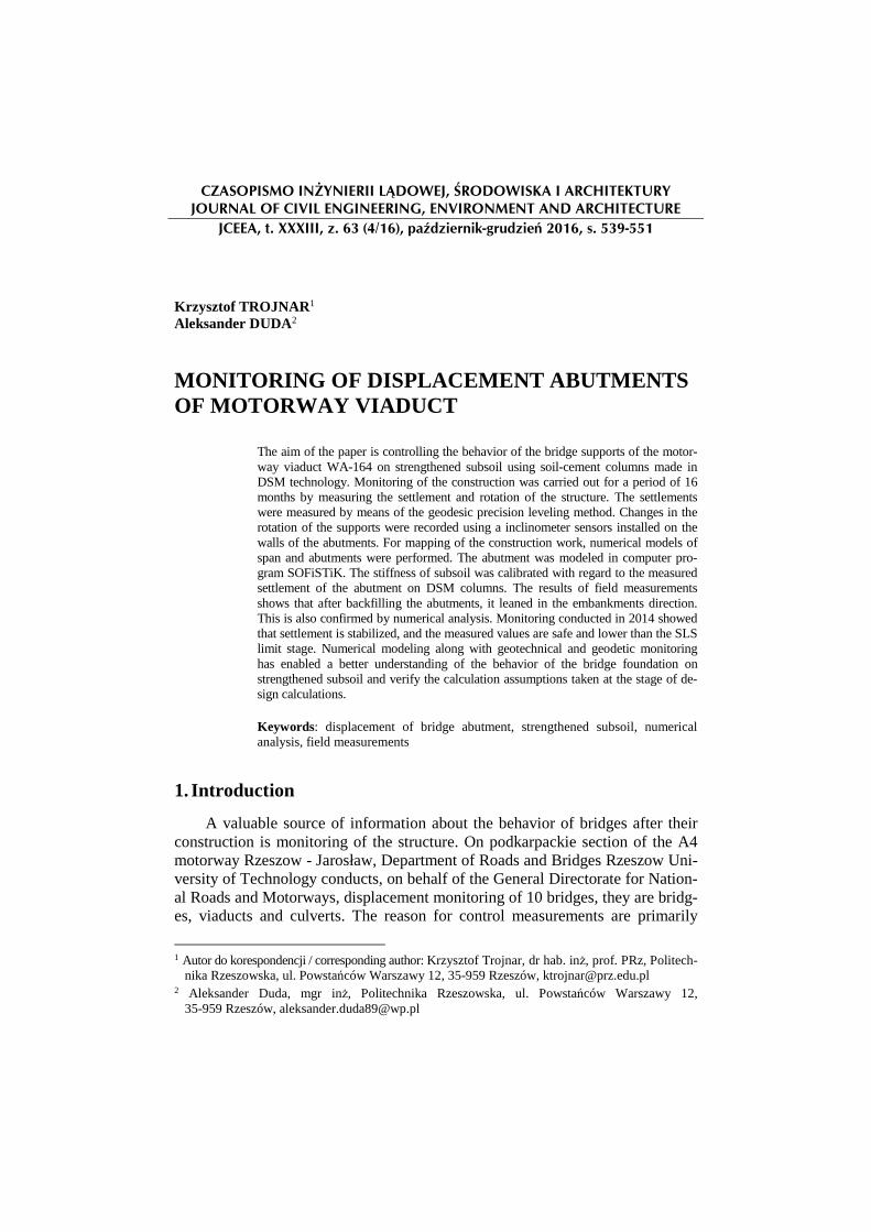
Road viaduct WA-164 is located within the A4 motorway between Rzeszow - Jarosław in km 582+247.98. There is a passage of local road 1384R under the viaduct between Terliczka - Trzebownisko. The communication sys-tem in the area of the object is shown on Fig. 1.
Fig. 1. The viaduct WA-164 A4 motorway
Rys. 1. Wiadukt WA-164 w ciągu autostrady A4
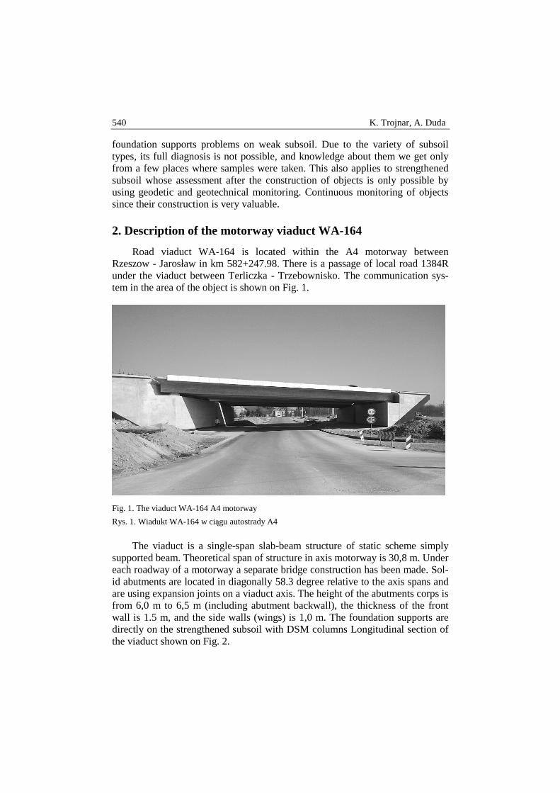
The viaduct is a single-span slab-beam structure of static scheme simply supported beam. Theoretical span of structure in axis motorway is 30,8 m. Under each roadway of a motorway a separate bridge construction has been made. Sol-id abutments are located in diagonally 58.3 degree relative to the axis spans and are using expansion joints on a viaduct axis. The height of the abutments corps is from 6,0 m to 6,5 m (including abutment backwall), the thickness of the front wall is 1.5 m, and the side walls (wings) is 1,0 m. The foundation supports are directly on the strengthened subsoil with DSM columns Longitudinal section of the viaduct shown on Fig. 2.
Monitoring of displacement abutments of motorway viaduct 541
Fig. 2. Longitudinal section of the viaduct WA-164
Rys. 2. Przekrój podłuiżny wiaduktu WA-164
Abu
tmen
t A
Abu
tmen
t B
DS
M c
olu
mn
DS
M c
olu
mn
542 K. Trojnar, A. Duda
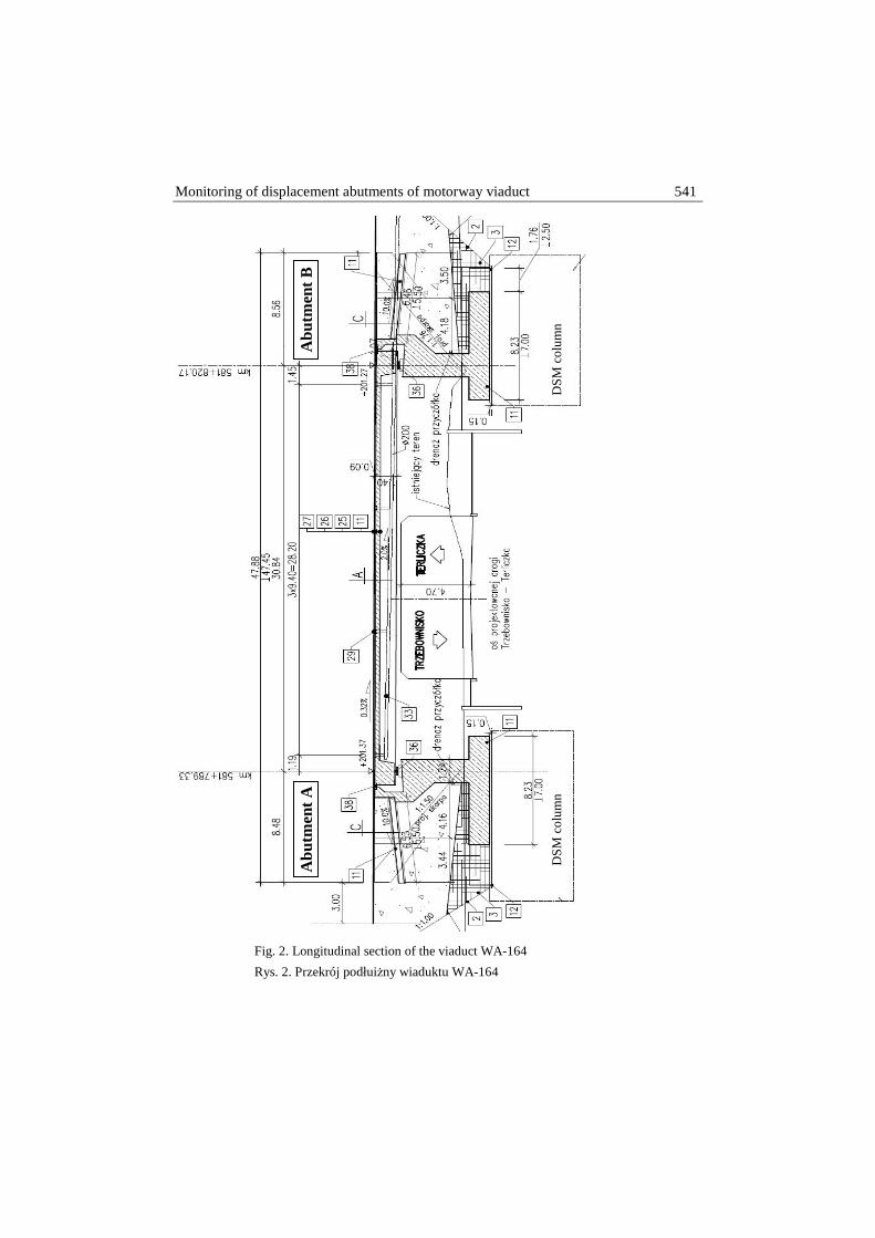
Fig. 3. Cross section of the viaduct and view the abutment A with an indication weak soil layer on geotechnical profile
Rys. 3. Przekrój poprzeczny wiaduktu oraz widok przyczółka A, z zaznaczeniem warstw słabego podłoża w profile geotechnicznym
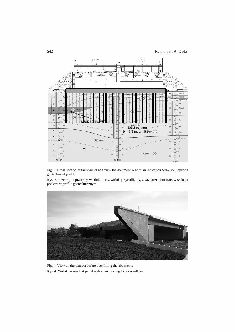
Fig. 4. View on the viaduct before backfilling the abutments
Rys. 4. Widok na wiadukt przed wykonaniem zasypki przyczółków
DSM column D = 0.8 m, L = 5.5 m
Monitoring of displacement abutments of motorway viaduct 543
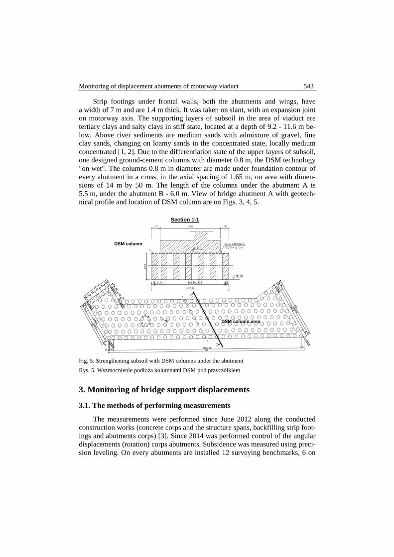
Strip footings under frontal walls, both the abutments and wings, have a width of 7 m and are 1.4 m thick. It was taken on slant, with an expansion joint on motorway axis. The supporting layers of subsoil in the area of viaduct are tertiary clays and salty clays in stiff state, located at a depth of 9.2 - 11.6 m be-low. Above river sediments are medium sands with admixture of gravel, fine clay sands, changing on loamy sands in the concentrated state, locally medium concentrated [1, 2]. Due to the differentiation state of the upper layers of subsoil, one designed ground-cement columns with diameter 0.8 m, the DSM technology "on wet". The columns 0.8 m in diameter are made under foundation contour of every abutment in a cross, in the axial spacing of 1.65 m, on area with dimen-sions of 14 m by 50 m. The length of the columns under the abutment A is 5.5 m, under the abutment B - 6.0 m. View of bridge abutment A with geotech-nical profile and location of DSM column are on Figs. 3, 4, 5.
Fig. 5. Strengthening subsoil with DSM columns under the abutment
Rys. 5. Wszmocnienie podłoża kolumnami DSM pod przyczółkiem
3. Monitoring of bridge support displacements
3.1. The methods of performing measurements
The measurements were performed since June 2012 along the conducted construction works (concrete corps and the structure spans, backfilling strip foot-ings and abutments corps) [3]. Since 2014 was performed control of the angular displacements (rotation) corps abutments. Subsidence was measured using preci-sion leveling. On every abutments are installed 12 surveying benchmarks, 6 on
DSM column area
Section 1-1
DSM column
544 K. Trojnar, A. Duda
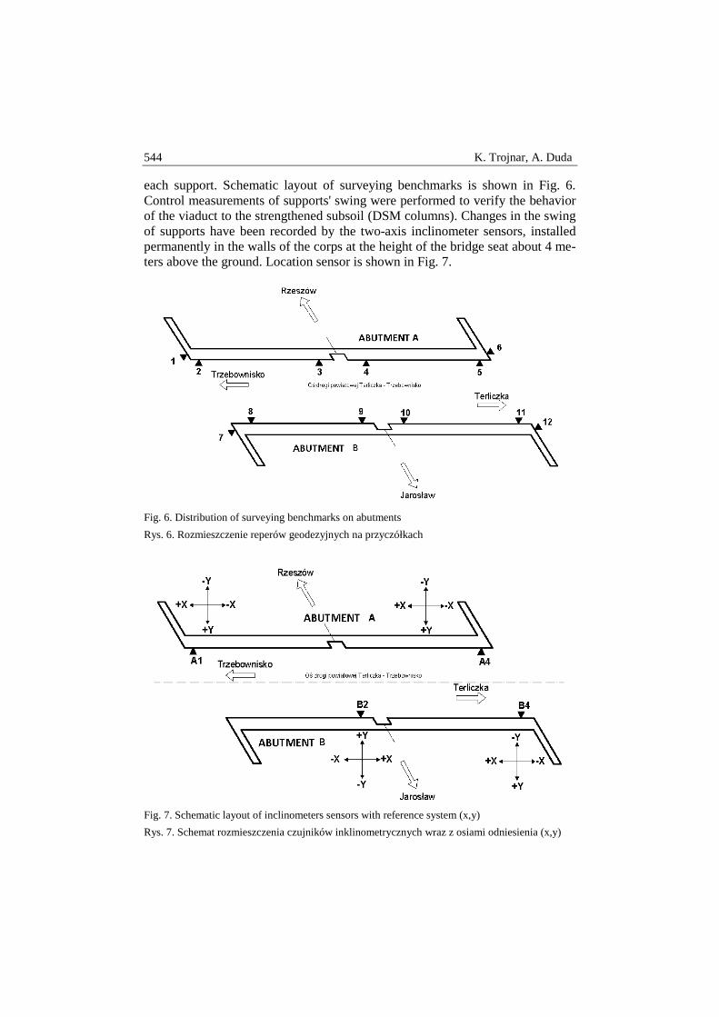
each support. Schematic layout of surveying benchmarks is shown in Fig. 6. Control measurements of supports' swing were performed to verify the behavior of the viaduct to the strengthened subsoil (DSM columns). Changes in the swing of supports have been recorded by the two-axis inclinometer sensors, installed permanently in the walls of the corps at the height of the bridge seat about 4 me-ters above the ground. Location sensor is shown in Fig. 7.
Fig. 6. Distribution of surveying benchmarks on abutments
Rys. 6. Rozmieszczenie reperów geodezyjnych na przyczółkach
Fig. 7. Schematic layout of inclinometers sensors with reference system (x,y)
Rys. 7. Schemat rozmieszczenia czujników inklinometrycznych wraz z osiami odniesienia (x,y)
Monitoring of displacement abutments of motorway viaduct 545
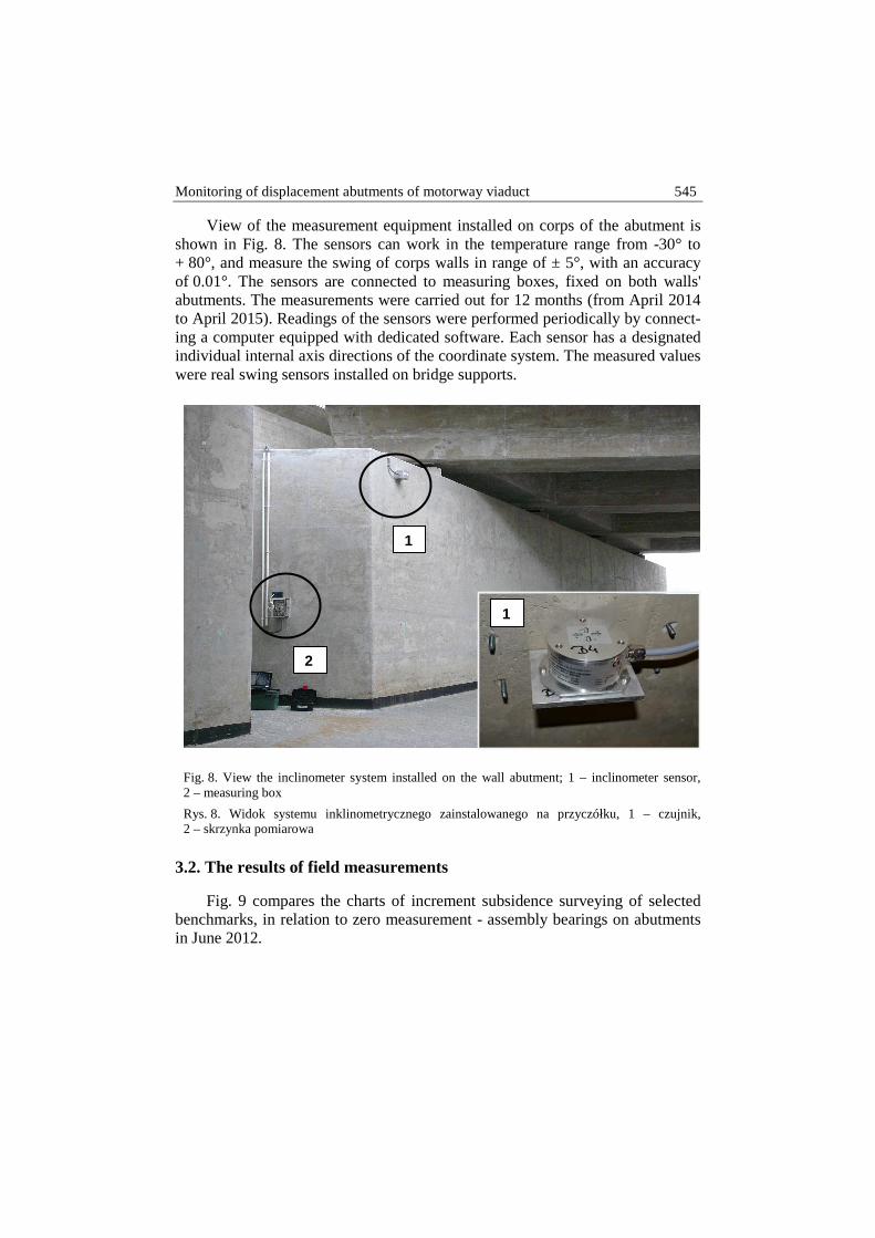
View of the measurement equipment installed on corps of the abutment is shown in Fig. 8. The sensors can work in the temperature range from -30° to + 80°, and measure the swing of corps walls in range of ± 5°, with an accuracy of 0.01°. The sensors are connected to measuring boxes, fixed on both walls' abutments. The measurements were carried out for 12 months (from April 2014 to April 2015). Readings of the sensors were performed periodically by connect-ing a computer equipped with dedicated software. Each sensor has a designated individual internal axis directions of the coordinate system. The measured values were real swing sensors installed on bridge supports.
Fig. 8. View the inclinometer system installed on the wall abutment; 1 – inclinometer sensor, 2 – measuring box
Rys. 8. Widok systemu inklinometrycznego zainstalowanego na przyczółku, 1 – czujnik, 2 – skrzynka pomiarowa
3.2. The results of field measurements
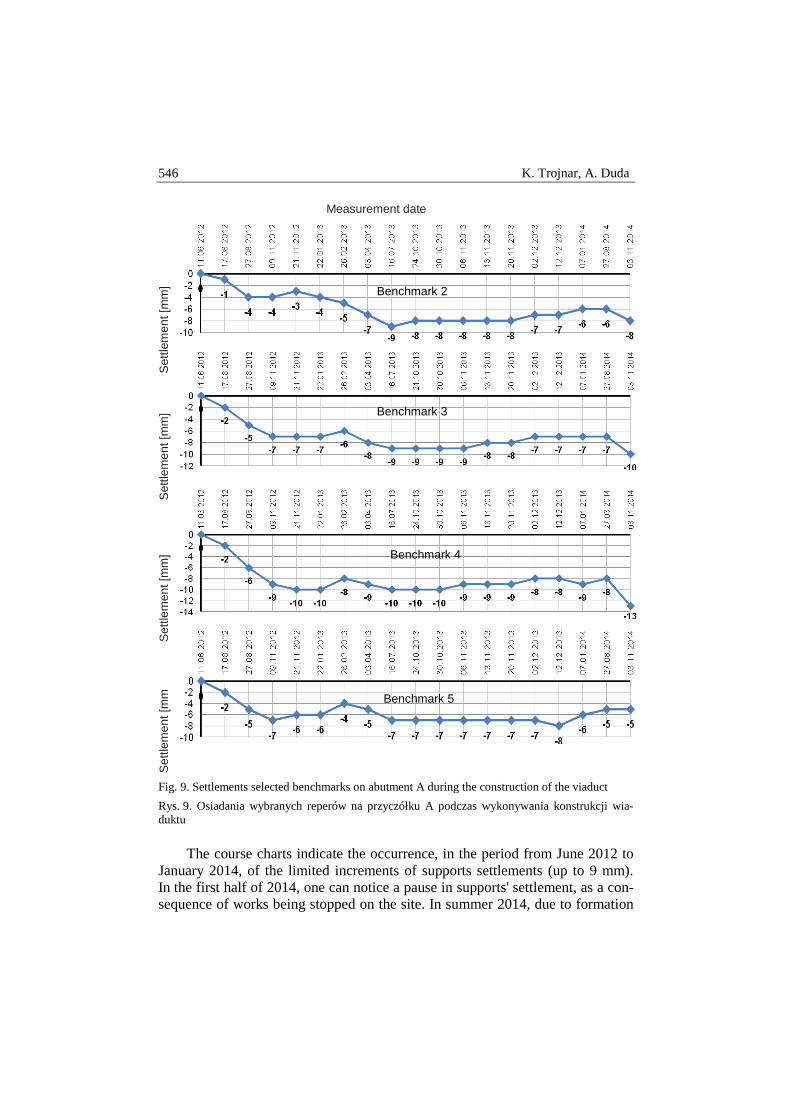
Fig. 9 compares the charts of increment subsidence surveying of selected benchmarks, in relation to zero measurement - assembly bearings on abutments in June 2012.
1
2
1
546 K. Trojnar, A. Duda
Fig. 9. Settlements selected benchmarks on abutment A during the construction of the viaduct
Rys. 9. Osiadania wybranych reperów na przyczółku A podczas wykonywania konstrukcji wia-duktu
The course charts indicate the occurrence, in the period from June 2012 to January 2014, of the limited increments of supports settlements (up to 9 mm). In the first half of 2014, one can notice a pause in supports' settlement, as a con-sequence of works being stopped on the site. In summer 2014, due to formation
Measurement date
Set
tlem
ent [
mm
] S
ettle
men
t [m
m]
Set
tlem
ent [
mm
] S
ettle
men
t [m
m
Benchmark 2
Benchmark 3
Benchmark 4
Benchmark 5
Monitoring of displacement abutments of motorway viaduct 547
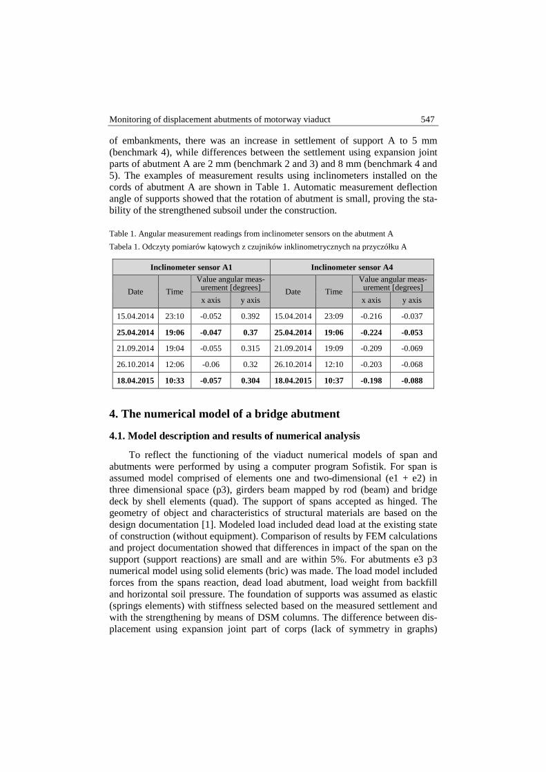
of embankments, there was an increase in settlement of support A to 5 mm (benchmark 4), while differences between the settlement using expansion joint parts of abutment A are 2 mm (benchmark 2 and 3) and 8 mm (benchmark 4 and 5). The examples of measurement results using inclinometers installed on the cords of abutment A are shown in Table 1. Automatic measurement deflection angle of supports showed that the rotation of abutment is small, proving the sta-bility of the strengthened subsoil under the construction.
Table 1. Angular measurement readings from inclinometer sensors on the abutment A
Tabela 1. Odczyty pomiarów kątowych z czujników inklinometrycznych na przyczółku A
Inclinometer sensor A1 Inclinometer sensor A4
Date Time
Value angular meas-urement [degrees] Date Time
Value angular meas-urement [degrees]
x axis y axis x axis y axis
15.04.2014 23:10 -0.052 0.392 15.04.2014 23:09 -0.216 -0.037
25.04.2014 19:06 -0.047 0.37 25.04.2014 19:06 -0.224 -0.053
21.09.2014 19:04 -0.055 0.315 21.09.2014 19:09 -0.209 -0.069
26.10.2014 12:06 -0.06 0.32 26.10.2014 12:10 -0.203 -0.068
18.04.2015 10:33 -0.057 0.304 18.04.2015 10:37 -0.198 -0.088
4. The numerical model of a bridge abutment
4.1. Model description and results of numerical analysis
To reflect the functioning of the viaduct numerical models of span and abutments were performed by using a computer program Sofistik. For span is assumed model comprised of elements one and two-dimensional (e1 + e2) in three dimensional space (p3), girders beam mapped by rod (beam) and bridge deck by shell elements (quad). The support of spans accepted as hinged. The geometry of object and characteristics of structural materials are based on the design documentation [1]. Modeled load included dead load at the existing state of construction (without equipment). Comparison of results by FEM calculations and project documentation showed that differences in impact of the span on the support (support reactions) are small and are within 5%. For abutments e3 p3 numerical model using solid elements (bric) was made. The load model included forces from the spans reaction, dead load abutment, load weight from backfill and horizontal soil pressure. The foundation of supports was assumed as elastic (springs elements) with stiffness selected based on the measured settlement and with the strengthening by means of DSM columns. The difference between dis-placement using expansion joint part of corps (lack of symmetry in graphs)
548 K. Trojnar, A. Duda
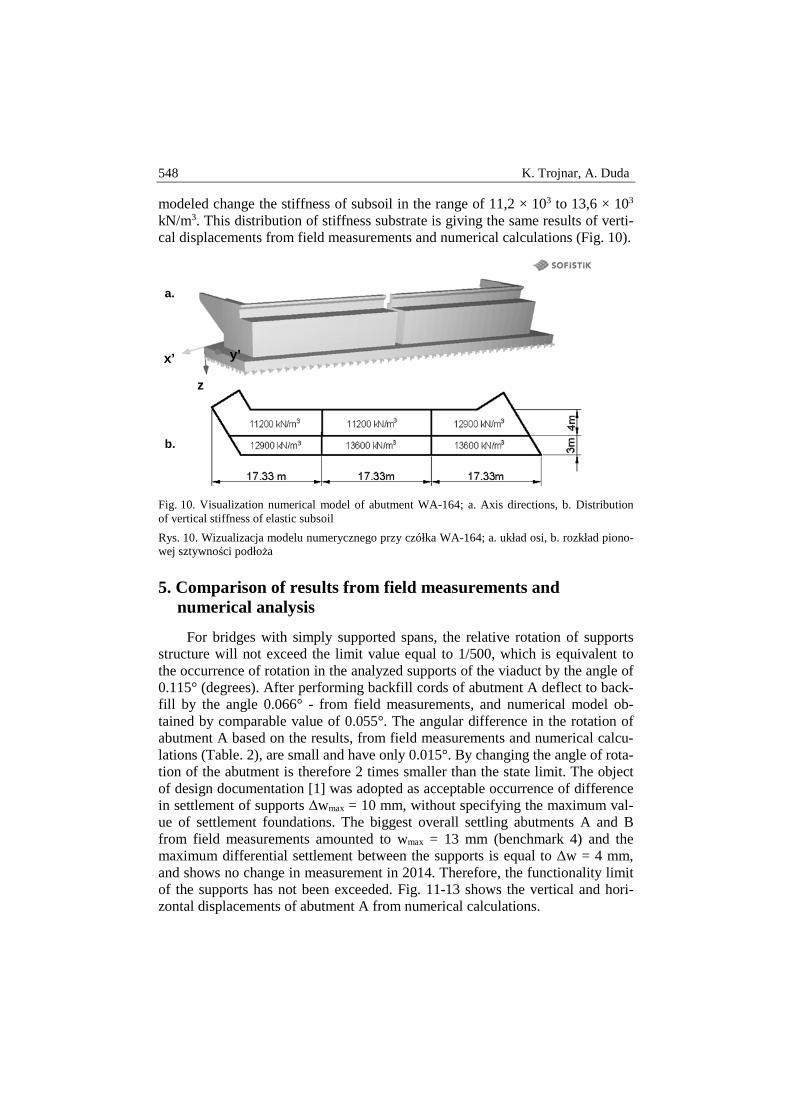
modeled change the stiffness of subsoil in the range of 11,2 × 10³ to 13,6 × 10³ kN/m3. This distribution of stiffness substrate is giving the same results of verti-cal displacements from field measurements and numerical calculations (Fig. 10).
Fig. 10. Visualization numerical model of abutment WA-164; a. Axis directions, b. Distribution of vertical stiffness of elastic subsoil
Rys. 10. Wizualizacja modelu numerycznego przy czółka WA-164; a. układ osi, b. rozkład piono-wej sztywności podłoża
5. Comparison of results from field measurements and numerical analysis
For bridges with simply supported spans, the relative rotation of supports structure will not exceed the limit value equal to 1/500, which is equivalent to the occurrence of rotation in the analyzed supports of the viaduct by the angle of 0.115° (degrees). After performing backfill cords of abutment A deflect to back-fill by the angle 0.066° - from field measurements, and numerical model ob-tained by comparable value of 0.055°. The angular difference in the rotation of abutment A based on the results, from field measurements and numerical calcu-lations (Table. 2), are small and have only 0.015°. By changing the angle of rota-tion of the abutment is therefore 2 times smaller than the state limit. The object of design documentation [1] was adopted as acceptable occurrence of difference in settlement of supports ∆wmax = 10 mm, without specifying the maximum val-ue of settlement foundations. The biggest overall settling abutments A and B from field measurements amounted to wmax = 13 mm (benchmark 4) and the maximum differential settlement between the supports is equal to ∆w = 4 mm, and shows no change in measurement in 2014. Therefore, the functionality limit of the supports has not been exceeded. Fig. 11-13 shows the vertical and hori-zontal displacements of abutment A from numerical calculations.
z
y’ x’
a.
b.
Monitoring of displacement abutments of motorway viaduct 549
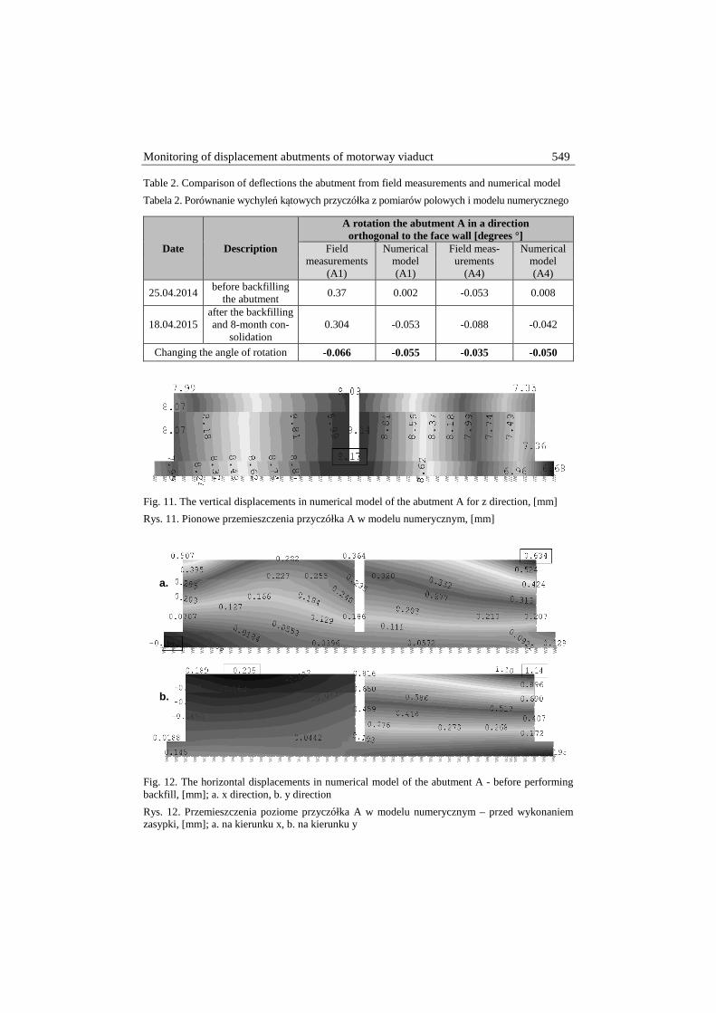
Table 2. Comparison of deflections the abutment from field measurements and numerical model
Tabela 2. Porównanie wychyleń kątowych przyczółka z pomiarów polowych i modelu numerycznego
Date Description
A rotation the abutment A in a direction orthogonal to the face wall [degrees °]
Field measurements
(A1)
Numerical model (A1)
Field meas-urements
(A4)
Numerical model (A4)
25.04.2014 before backfilling
the abutment 0.37 0.002 -0.053 0.008
18.04.2015 after the backfilling and 8-month con-
solidation 0.304 -0.053 -0.088 -0.042
Changing the angle of rotation -0.066 -0.055 -0.035 -0.050
Fig. 11. The vertical displacements in numerical model of the abutment A for z direction, [mm]
Rys. 11. Pionowe przemieszczenia przyczółka A w modelu numerycznym, [mm]
Fig. 12. The horizontal displacements in numerical model of the abutment A - before performing backfill, [mm]; a. x direction, b. y direction
Rys. 12. Przemieszczenia poziome przyczółka A w modelu numerycznym – przed wykonaniem zasypki, [mm]; a. na kierunku x, b. na kierunku y
a.
b.
550 K. Trojnar, A. Duda
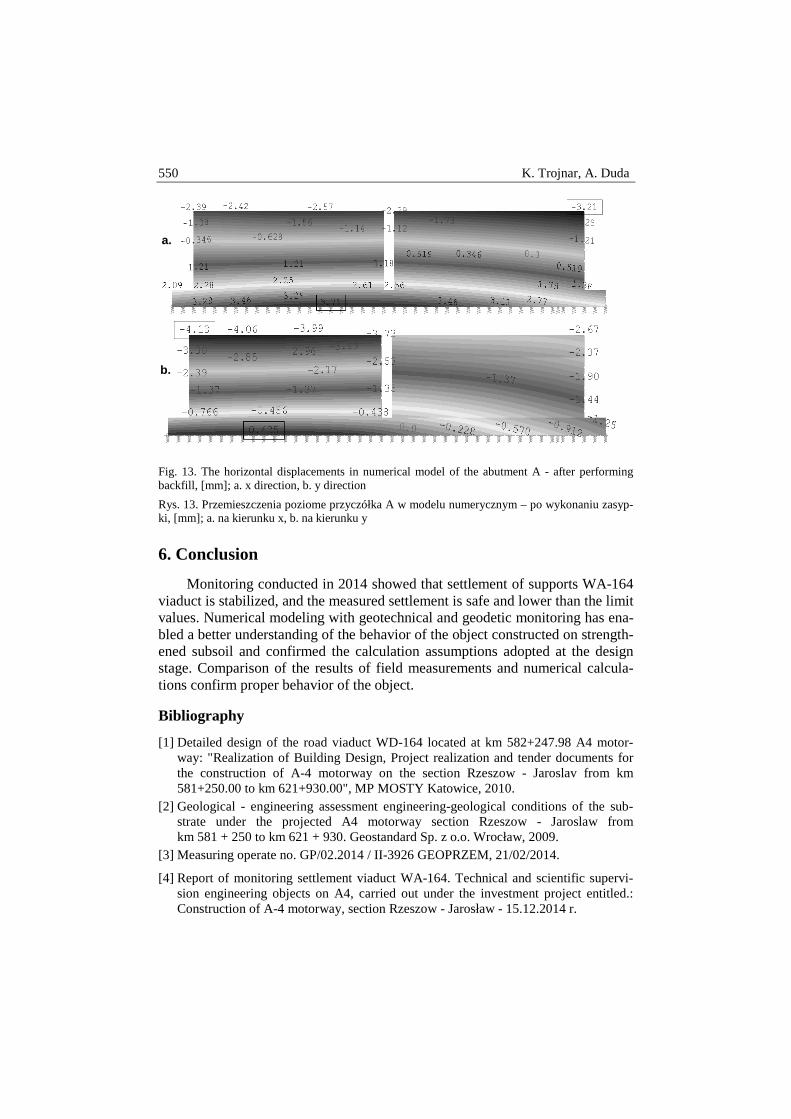
Fig. 13. The horizontal displacements in numerical model of the abutment A - after performing backfill, [mm]; a. x direction, b. y direction
Rys. 13. Przemieszczenia poziome przyczółka A w modelu numerycznym – po wykonaniu zasyp-ki, [mm]; a. na kierunku x, b. na kierunku y
6. Conclusion
Monitoring conducted in 2014 showed that settlement of supports WA-164 viaduct is stabilized, and the measured settlement is safe and lower than the limit values. Numerical modeling with geotechnical and geodetic monitoring has ena-bled a better understanding of the behavior of the object constructed on strength-ened subsoil and confirmed the calculation assumptions adopted at the design stage. Comparison of the results of field measurements and numerical calcula-tions confirm proper behavior of the object.
Bibliography
[1] Detailed design of the road viaduct WD-164 located at km 582+247.98 A4 motor-way: "Realization of Building Design, Project realization and tender documents for the construction of A-4 motorway on the section Rzeszow - Jaroslav from km 581+250.00 to km 621+930.00", MP MOSTY Katowice, 2010.
[2] Geological - engineering assessment engineering-geological conditions of the sub-strate under the projected A4 motorway section Rzeszow - Jaroslaw from km 581 + 250 to km 621 + 930. Geostandard Sp. z o.o. Wrocław, 2009.
[3] Measuring operate no. GP/02.2014 / II-3926 GEOPRZEM, 21/02/2014.
[4] Report of monitoring settlement viaduct WA-164. Technical and scientific supervi-sion engineering objects on A4, carried out under the investment project entitled.: Construction of A-4 motorway, section Rzeszow - Jarosław - 15.12.2014 r.
a.
b.
Monitoring of displacement abutments of motorway viaduct 551
MONITORING PRZEMIESZCZE Ń PRZYCZÓŁKU WIADUKTU AUTOSTRADOWEGO
S t r e s z c z e n i e
Celem referatu jest kontrola zachowania się podpór mostowych, wiaduktu autostradowego WA-164 na wzmocnionym podłożu, poprzez kolumny gruntowo – cementowe wykonane w tech-nologii DSM. Monitoring konstrukcji prowadzono przez okres 16 miesięcy, mierząc osiadania i obroty konstrukcji. Osiadania były mierzone metodą niwelacji precyzyjnej. Zmiana obrotów podpór była rejestrowana przy pomocy czujników inklinometrycznych, zainstalowanych na ścia-nie przyczółku. Dla odwzorowania pracy konstrukcji wykonano model numeryczny przęsła oraz przyczółku. Przyczółek zamodelowano w programie komputerowym SOFiSTiK. Sztywność pod-łoża była kalibrowana w odniesieniu do pomiarów osiadania przyczółka na kolumnach DSM. Po-miary polowe pokazują, że po wykonaniu zasypki przyczółka, wychylił się on w stronę nasypu. Potwierdza to również analiza numeryczna. Monitoring prowadzony w roku 2014 pokazał, że osiadania są stabilne, a pomierzone wartości bezpieczne i mniejsze niż dopuszczalne dla stanu granicznego użytkowania. Modelowanie numeryczne wraz z geotechnicznym i geodezyjnym mo-nitoringiem pozwala lepiej zrozumieć zachowanie się fundamentu mostowego na wzmocnionym podłożu oraz zweryfikować założenia obliczeniowe podjęte na etapie projektowania. Słowa kluczowe: przemieszczenia przyczółku mostowego, wzmocnione podłoże, numeryczna analiza, pomiary polowe DOI:10.7862/rb.2016.298 Przesłano do redakcji: 5.12.2016 r. Przyjęto do druku: 20.12.2016 r.

552 K. Trojnar, A. Duda


![Smart motorway design guide - Roads and Maritime Services · 2017-04-21 · Smart [1]Motorway Technical Direction and the Smart Motorway Guidelines[2]. 1.2 Smart motorway document](https://img.pdfslide.net/doc/110x75/5e764c607cf5f006800a1c9a/smart-motorway-design-guide-roads-and-maritime-services-2017-04-21-smart-1motorway.jpg)