Embed Size (px)
Citation preview
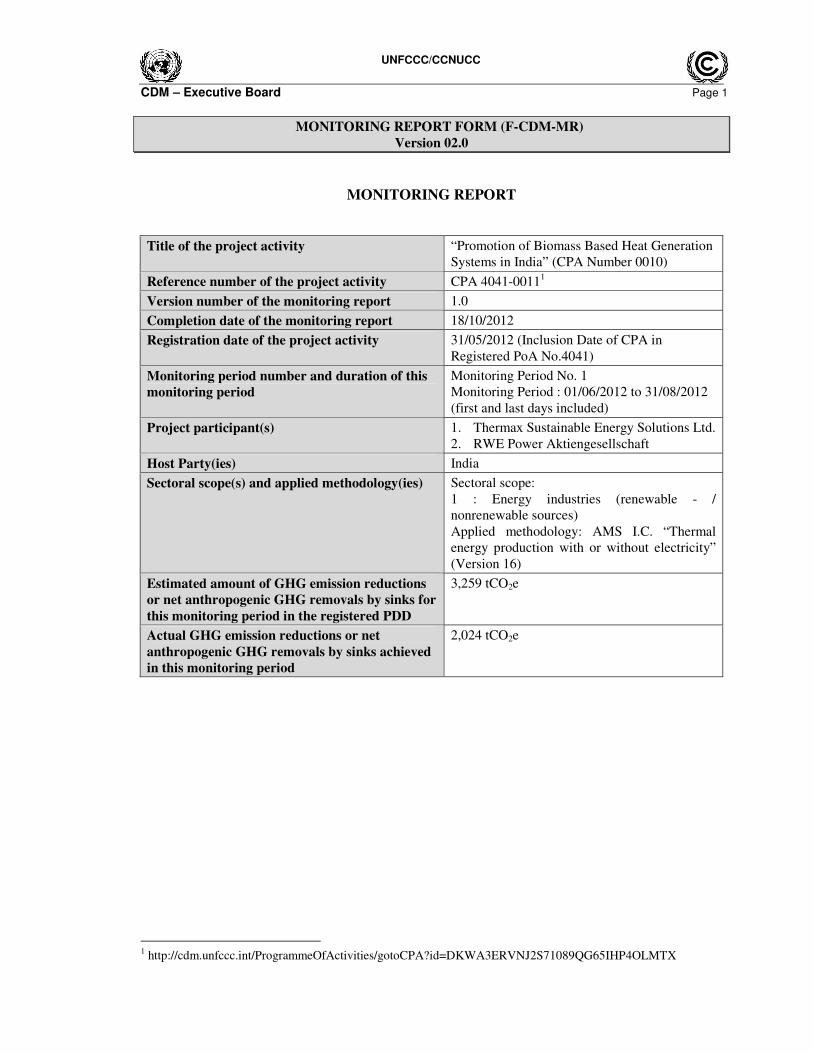
UNFCCC/CCNUCC
CDM – Executive Board Page 1
MONITORING REPORT FORM (F-CDM-MR)
Version 02.0
MONITORING REPORT
Title of the project activity “Promotion of Biomass Based Heat Generation
Systems in India” (CPA Number 0010)
Reference number of the project activity CPA 4041-00111
Version number of the monitoring report 1.0
Completion date of the monitoring report 18/10/2012
Registration date of the project activity 31/05/2012 (Inclusion Date of CPA in
Registered PoA No.4041)
Monitoring period number and duration of this
monitoring period
Monitoring Period No. 1
Monitoring Period : 01/06/2012 to 31/08/2012
(first and last days included)
Project participant(s) 1. Thermax Sustainable Energy Solutions Ltd.
2. RWE Power Aktiengesellschaft
Host Party(ies) India
Sectoral scope(s) and applied methodology(ies) Sectoral scope:
1 : Energy industries (renewable - /
nonrenewable sources)
Applied methodology: AMS I.C. “Thermal
energy production with or without electricity”
(Version 16)
Estimated amount of GHG emission reductions
or net anthropogenic GHG removals by sinks for
this monitoring period in the registered PDD
3,259 tCO2e
Actual GHG emission reductions or net
anthropogenic GHG removals by sinks achieved
in this monitoring period
2,024 tCO2e
1 http://cdm.unfccc.int/ProgrammeOfActivities/gotoCPA?id=DKWA3ERVNJ2S71089QG65IHP4OLMTX
UNFCCC/CCNUCC
CDM – Executive Board Page 2
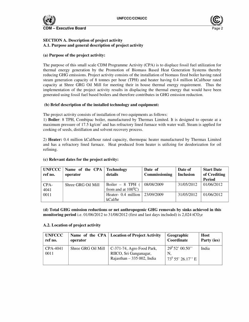
SECTION A. Description of project activity
A.1. Purpose and general description of project activity
(a) Purpose of the project activity:
The purpose of this small scale CDM Programme Activity (CPA) is to displace fossil fuel utilization for
thermal energy generation by the Promotion of Biomass Based Heat Generation Systems thereby
reducing GHG emissions. Project activity consists of the installation of biomass fired boiler having rated
steam generation capacity of 8 tonnes per hour (TPH) and heater having 0.4 million kCal/hour rated
capacity at Shree GRG Oil Mill for meeting their in house thermal energy requirement. Thus the
implementation of the project activity results in displacing the thermal energy that would have been
generated using fossil fuel based boilers and therefore contributes in GHG emission reduction.
(b) Brief description of the installed technology and equipment:
The project activity consists of installation of two equipments as follows:
1) Boiler: 8 TPH, Combipac boiler, manufactured by Thermax Limited. It is designed to operate at a
maximum pressure of 17.5 kg/cm2 and has refractory lined furnace with water wall. Steam is applied for
cooking of seeds, distillation and solvent recovery process.
2) Heater: 0.4 million kCal/hour rated capacity, thermopac heater manufactured by Thermax Limited
and has a refractory lined furnace. Heat produced from heater is utilizing for deodorization for oil
refining.
(c) Relevant dates for the project activity:
UNFCCC
ref no.
Name of the CPA
operator
Technology
details
Date of
Commissioning
Date of
Inclusion
Start Date
of Crediting
Period
Boiler – 8 TPH (
from and at 1000C)
08/08/2009 31/05/2012 01/06/2012 CPA-
4041
0011
Shree GRG Oil Mill
Heater- 0.4 million
kCal/hr
23/09/2009 31/05/2012 01/06/2012
(d) Total GHG emission reductions or net anthropogenic GHG removals by sinks achieved in this
monitoring period i.e. 01/06/2012 to 31/08/2012 (first and last days included) is 2,024 tCO2e
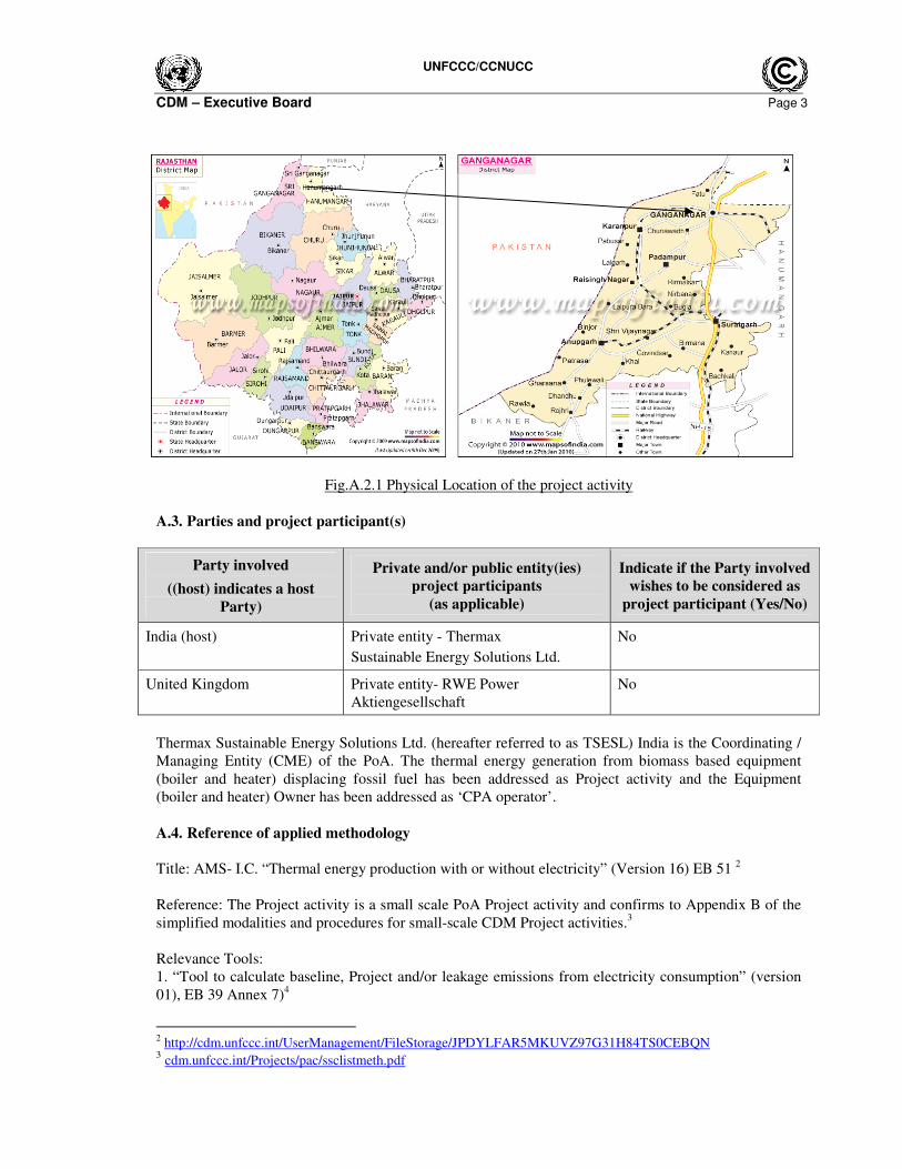
A.2. Location of project activity
UNFCCC
ref no.
Name of the CPA
operator
Location of Project Activity Geographic
Coordinate
Host
Party (ies)
CPA-4041
0011
Shree GRG Oil Mill C-371-74, Agro Food Park,
RIICO, Sri Ganganagar,
Rajasthan – 335 002, India
290 52’ 00.50’’
N,
730 55’ 26.17’’ E
India
UNFCCC/CCNUCC
CDM – Executive Board Page 3
Fig.A.2.1 Physical Location of the project activity
A.3. Parties and project participant(s)
Party involved
((host) indicates a host
Party)
Private and/or public entity(ies)
project participants
(as applicable)
Indicate if the Party involved
wishes to be considered as
project participant (Yes/No)
India (host) Private entity - Thermax
Sustainable Energy Solutions Ltd.
No
United Kingdom Private entity- RWE Power
Aktiengesellschaft
No
Thermax Sustainable Energy Solutions Ltd. (hereafter referred to as TSESL) India is the Coordinating /
Managing Entity (CME) of the PoA. The thermal energy generation from biomass based equipment
(boiler and heater) displacing fossil fuel has been addressed as Project activity and the Equipment
(boiler and heater) Owner has been addressed as ‘CPA operator’.
A.4. Reference of applied methodology
Title: AMS- I.C. “Thermal energy production with or without electricity” (Version 16) EB 51 2
Reference: The Project activity is a small scale PoA Project activity and confirms to Appendix B of the
simplified modalities and procedures for small-scale CDM Project activities.3
Relevance Tools:
1. “Tool to calculate baseline, Project and/or leakage emissions from electricity consumption” (version
01), EB 39 Annex 7)4
2 http://cdm.unfccc.int/UserManagement/FileStorage/JPDYLFAR5MKUVZ97G31H84TS0CEBQN
3 cdm.unfccc.int/Projects/pac/ssclistmeth.pdf

UNFCCC/CCNUCC
CDM – Executive Board Page 4
2. “Tool to calculate the emission factor for an electricity system” (Version 02), EB 50 Annex 145
3. “General Guidance on leakage in Biomass Project activities” (Version 03); EB 47; Annex 286
4. “Tool to calculate Project or leakage CO2 emissions from fossil fuel combustion” (version 02) EB 41
Annex 117
A.5. Crediting period of project activity
Type: Fixed Crediting period
Start date of Crediting Period: 01/06/2012
Length of the crediting period: 10 Years
SECTION B. Implementation of project activity
B.1. Description of implemented registered project activity
i. Description of installed technology:
The thermal energy generated from biomass firing in the boiler furnace is transferred to the boiler water,
through the heat transfer surfaces of pressure parts, which is converted to steam. This steam acts as a
medium of transfer of thermal energy in the process for heating.
The biomass fired heaters consist of thermic fluid / thermal oil heaters, pressurized and non pressurized
hot water generators, which work on closed loop pipe line system, for transferring the thermal energy
indirectly, to the process through the heat transfer medium like thermic fluids / thermal oil or pressurized
/ non pressurized water. The biomass fired heaters are similar to the boilers, as both pick up the heat
from the biomass fuel combustion & transfer it to the process/heat utilities. The heaters transfer the
thermal energy in the form of heat to the user which could be a process or heat utilities in a closed loop
piping system.
4 http://cdm.unfccc.int/methodologies/PAmethodologies/tools/am-tool-05-v1.pdf
5 http://cdm.unfccc.int/EB/050/eb50_repan14.pdf
6 http://cdm.unfccc.int/EB/047/eb47_repan28.pdf
7 http://cdm.unfccc.int/EB/041/eb41_repan11.pdf
UNFCCC/CCNUCC
CDM – Executive Board Page 5
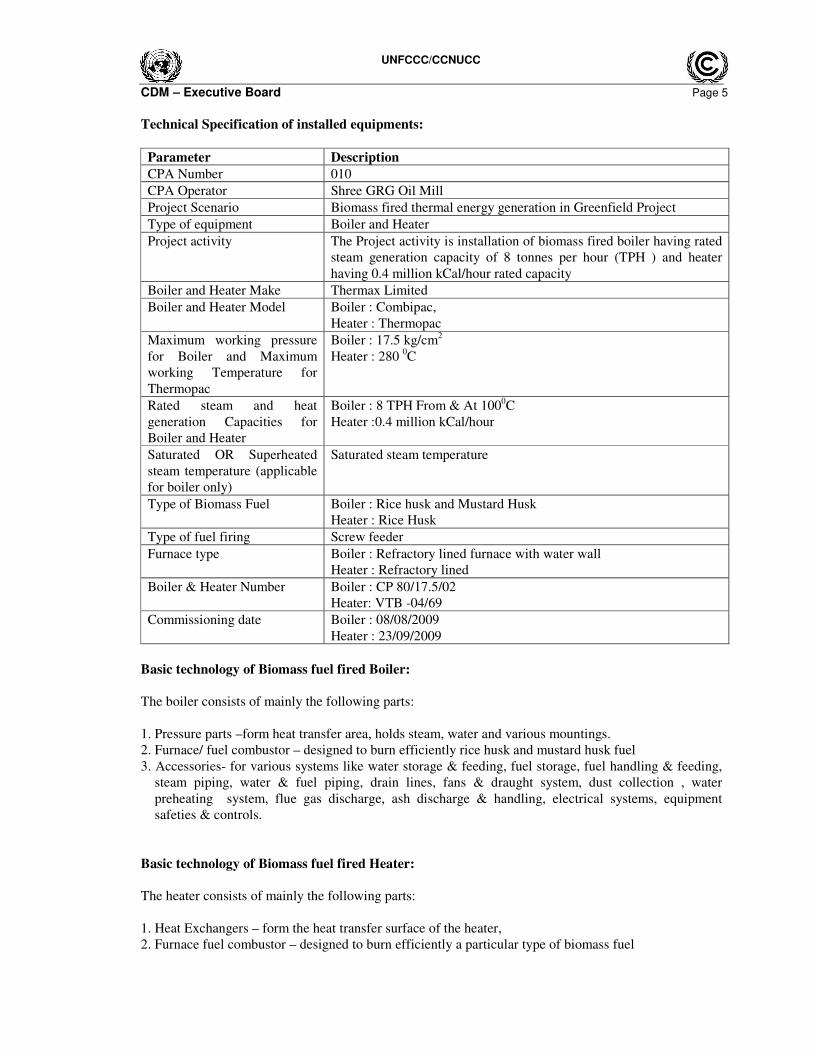
Technical Specification of installed equipments:
Parameter Description
CPA Number 010
CPA Operator Shree GRG Oil Mill
Project Scenario Biomass fired thermal energy generation in Greenfield Project
Type of equipment Boiler and Heater
Project activity The Project activity is installation of biomass fired boiler having rated
steam generation capacity of 8 tonnes per hour (TPH ) and heater
having 0.4 million kCal/hour rated capacity
Boiler and Heater Make Thermax Limited
Boiler and Heater Model Boiler : Combipac,
Heater : Thermopac
Maximum working pressure
for Boiler and Maximum
working Temperature for
Thermopac
Boiler : 17.5 kg/cm2
Heater : 280 0C
Rated steam and heat
generation Capacities for
Boiler and Heater
Boiler : 8 TPH From & At 1000C
Heater :0.4 million kCal/hour
Saturated OR Superheated
steam temperature (applicable
for boiler only)
Saturated steam temperature
Type of Biomass Fuel Boiler : Rice husk and Mustard Husk
Heater : Rice Husk
Type of fuel firing Screw feeder
Furnace type Boiler : Refractory lined furnace with water wall
Heater : Refractory lined
Boiler & Heater Number Boiler : CP 80/17.5/02
Heater: VTB -04/69
Commissioning date Boiler : 08/08/2009
Heater : 23/09/2009
Basic technology of Biomass fuel fired Boiler:
The boiler consists of mainly the following parts:
1. Pressure parts –form heat transfer area, holds steam, water and various mountings.
2. Furnace/ fuel combustor – designed to burn efficiently rice husk and mustard husk fuel
3. Accessories- for various systems like water storage & feeding, fuel storage, fuel handling & feeding,
steam piping, water & fuel piping, drain lines, fans & draught system, dust collection , water
preheating system, flue gas discharge, ash discharge & handling, electrical systems, equipment
safeties & controls.
Basic technology of Biomass fuel fired Heater:
The heater consists of mainly the following parts:
1. Heat Exchangers – form the heat transfer surface of the heater,
2. Furnace fuel combustor – designed to burn efficiently a particular type of biomass fuel
UNFCCC/CCNUCC
CDM – Executive Board Page 6
3. Accessories - for various systems like fuel storage, fuel handling & feeding, heat transfer fluid/water
pipe lines, fans & draught system, flue gas discharge, ash discharge & handling, electrical system,
equipment safety & controls, de-aerator & expansion Tank, heat transfer fluid/treated water system and
storage.
The CPA operator has utilized biomasses for heat generation i.e. Rice Husk and Mustard Husk which is
in compliance with “Definition of Renewable Biomass Annex 18 of EB 23” and “Glossary of CDM
Terms – Version -05.
This CPA involves no technology transfer from Annex 1 country to the host country.
ii.Actual operation of the project activity during this monitoring period:
The project is currently operational as per the registered monitoring plan and is implemented in
compliance with the registered CPA-DD. The project complied with all legal requirements during the
current monitoring period. The project performance is normal and there was no any such major events
occurred during the monitoring period, which affects the monitoring plan of the project activity like
equipment retrofitting, Capacity addition etc.
B.2. Post registration changes
B.2.1. Temporary deviations from registered monitoring plan or applied methodology
There are no temporary deviations applied for the registered monitoring plan during this monitoring
period
B.2.2. Corrections
There are no corrections to project information or parameters fixed at validation that have been
approved during this monitoring period or submitted with this monitoring report.
B.2.3. Permanent changes from registered monitoring plan or applied methodology
There are no permanent changes from the registered monitoring plan or applied methodology that have
been approved during this monitoring period or submitted with this monitoring report.
B.2.4. Changes to project design of registered project activity
There are no changes to the project design of the project activity that have been approved during this
monitoring period or submitted with this monitoring report.
B.2.5. Changes to start date of crediting period
There are no changes to the start date of the crediting period that have been approved during this
monitoring period or submitted with this monitoring report.
B.2.6. Types of changes specific to afforestation or reforestation project activity
Not applicable
SECTION C. Description of monitoring system
The biomass based Steam & Heat generation system parameters are monitored using Field Instruments,
Hardware & Software installed at Project site and Manual data recording in the log book. Measuring
instruments used for Monitoring Parameters are listed as follows
UNFCCC/CCNUCC
CDM – Executive Board Page 7
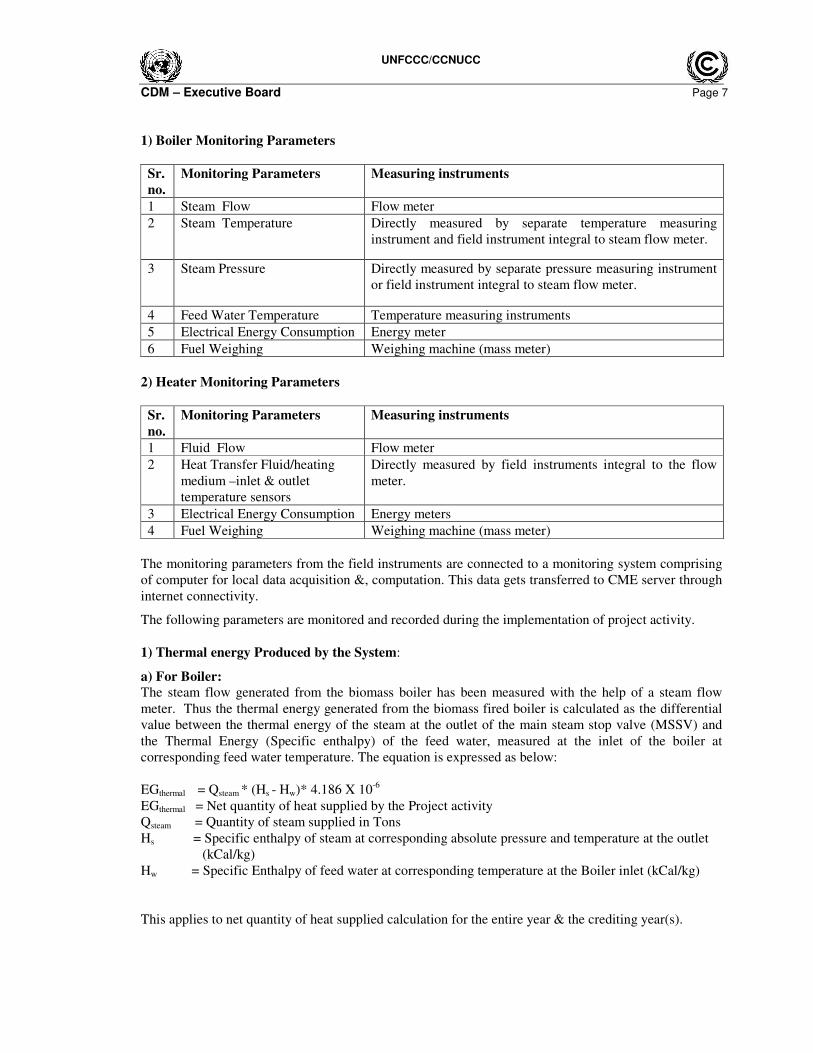
1) Boiler Monitoring Parameters
Sr.
no.
Monitoring Parameters Measuring instruments
1 Steam Flow Flow meter
2 Steam Temperature Directly measured by separate temperature measuring
instrument and field instrument integral to steam flow meter.
3 Steam Pressure Directly measured by separate pressure measuring instrument
or field instrument integral to steam flow meter.
4 Feed Water Temperature Temperature measuring instruments
5 Electrical Energy Consumption Energy meter
6 Fuel Weighing Weighing machine (mass meter)
2) Heater Monitoring Parameters
Sr.
no.
Monitoring Parameters Measuring instruments
1 Fluid Flow Flow meter
2 Heat Transfer Fluid/heating
medium –inlet & outlet
temperature sensors
Directly measured by field instruments integral to the flow
meter.
3 Electrical Energy Consumption Energy meters
4 Fuel Weighing Weighing machine (mass meter)
The monitoring parameters from the field instruments are connected to a monitoring system comprising
of computer for local data acquisition &, computation. This data gets transferred to CME server through
internet connectivity.
The following parameters are monitored and recorded during the implementation of project activity.
1) Thermal energy Produced by the System:
a) For Boiler:
The steam flow generated from the biomass boiler has been measured with the help of a steam flow
meter. Thus the thermal energy generated from the biomass fired boiler is calculated as the differential
value between the thermal energy of the steam at the outlet of the main steam stop valve (MSSV) and
the Thermal Energy (Specific enthalpy) of the feed water, measured at the inlet of the boiler at
corresponding feed water temperature. The equation is expressed as below:
EGthermal = Qsteam * (Hs - Hw)* 4.186 X 10⁻⁶
EGthermal = Net quantity of heat supplied by the Project activity
Qsteam = Quantity of steam supplied in Tons
Hs = Specific enthalpy of steam at corresponding absolute pressure and temperature at the outlet
(kCal/kg)
Hw = Specific Enthalpy of feed water at corresponding temperature at the Boiler inlet (kCal/kg)
This applies to net quantity of heat supplied calculation for the entire year & the crediting year(s).
UNFCCC/CCNUCC
CDM – Executive Board Page 8
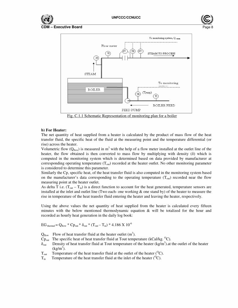
Fig. C.1.1 Schematic Representation of monitoring plan for a boiler
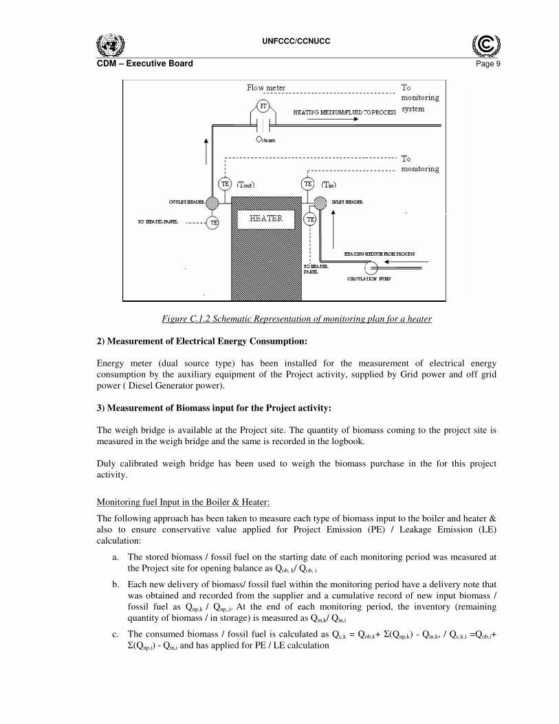
b) For Heater:
The net quantity of heat supplied from a heater is calculated by the product of mass flow of the heat
transfer fluid, the specific heat of the fluid at the measuring point and the temperature differential (or
rise) across the heater.
Volumetric flow (Qflow) is measured in m3 with the help of a flow meter installed at the outlet line of the
heater, the flow obtained is then converted to mass flow by multiplying with density (δ) which is
computed in the monitoring system which is determined based on data provided by manufacturer at
corresponding operating temperature (Tout) recorded at the heater outlet. No other monitoring parameter
is considered to determine this parameter.
Similarly the Cp, specific heat, of the heat transfer fluid is also computed in the monitoring system based
on the manufacturer’s data corresponding to the operating temperature (Tout) recorded near the flow
measuring point at the heater outlet.
As delta T i.e. (Tout – Tin) is a direct function to account for the heat generated, temperature sensors are
installed at the inlet and outlet line (Two each- one working & one stand by) of the heater to measure the
rise in temperature of the heat transfer fluid entering the heater and leaving the heater, respectively.
Using the above values the net quantity of heat supplied from the heater is calculated every fifteen
minutes with the below mentioned thermodynamic equation & will be totalized for the hour and
recorded as hourly heat generation in the daily log book:
EG thermal = Qflow * Cpout * δout * (Tout – Tin) * 4.186 X 10⁻⁶
Qflow Flow of heat transfer fluid at the heater outlet (m3).
Cpout The specific heat of heat transfer fluid at Tout temperature (kCal/kg. OC).
δout Density of heat transfer fluid at Tout temperature of the heater (kg/m3).at the outlet of the heater
(kg/m3).
Tout Temperature of the heat transfer fluid at the outlet of the heater (OC).
Tin Temperature of the heat transfer fluid at the inlet of the heater (OC).
UNFCCC/CCNUCC
CDM – Executive Board Page 9
Figure C.1.2 Schematic Representation of monitoring plan for a heater
2) Measurement of Electrical Energy Consumption:
Energy meter (dual source type) has been installed for the measurement of electrical energy
consumption by the auxiliary equipment of the Project activity, supplied by Grid power and off grid
power ( Diesel Generator power).
3) Measurement of Biomass input for the Project activity:
The weigh bridge is available at the Project site. The quantity of biomass coming to the project site is
measured in the weigh bridge and the same is recorded in the logbook.
Duly calibrated weigh bridge has been used to weigh the biomass purchase in the for this project
activity.
Monitoring fuel Input in the Boiler & Heater:
The following approach has been taken to measure each type of biomass input to the boiler and heater &
also to ensure conservative value applied for Project Emission (PE) / Leakage Emission (LE)
calculation:
a. The stored biomass / fossil fuel on the starting date of each monitoring period was measured at
the Project site for opening balance as Qob, k/ Qob, i
b. Each new delivery of biomass/ fossil fuel within the monitoring period have a delivery note that
was obtained and recorded from the supplier and a cumulative record of new input biomass /
fossil fuel as Qnp,k / Qnp,,i. At the end of each monitoring period, the inventory (remaining
quantity of biomass / in storage) is measured as Qin,k/ Qin,i
c. The consumed biomass / fossil fuel is calculated as Qc,k = Qob,k+ Σ(Qnp,k) - Qin,k, / Qc,k,i =Qob,i+
Σ(Qnp,i) - Qin,i and has applied for PE / LE calculation
UNFCCC/CCNUCC
CDM – Executive Board Page 10
Moisture gain or loss by the biomass is season dependent. Moisture sample is monitored on a monthly
basis. The above measurement method ensures the practical method for monitoring biomass / fossil fuel.
4) Measurement of Fossil fuel input for the Project activity:
The monitoring of the quantity of fossil fuel input is also based on above method (Sr. no. 3) of
measurement. However there was no fossil fuel consumed during the monitoring period for this project
activity.
Description of the Monitoring procedure:
1) Manual recording: The boiler & heater parameters have been manually recorded as indicated
above by the boiler & heater operational staff at site (CPA operator).This manual record of boiler
and heater log book has been maintained at site by CPA operator.
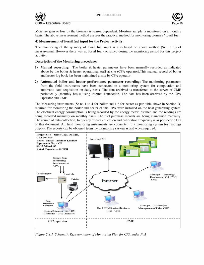
2) Automated boiler and heater performance parameter recording: The monitoring parameters
from the field instruments have been connected to a monitoring system for computation and
automatic data acquisition on daily basis. The data archived is transferred to the server of CME
periodically (monthly basis) using internet connection. The data has been archived by the CPA
Operator and CME.
The Measuring instruments (Sr no 1 to 4 for boiler and 1,2 for heater as per table above in Section D)
required for monitoring the boiler and heater of this CPA were installed on the heat generating system.
The electrical energy consumption is being recorded by the energy meter installed and the readings are
being recorded manually on monthly basis. The fuel purchase records are being maintained manually.
The source of data collection, frequency of data collection and calibration frequency is as per section D.2
of this document. All field monitoring instruments are connected to a monitoring system for readings
display. The reports can be obtained from the monitoring system as and when required.
Figure C.1.1 Schematic Representation of Monitoring Plan for CPA under PoA
UNFCCC/CCNUCC
CDM – Executive Board Page 11
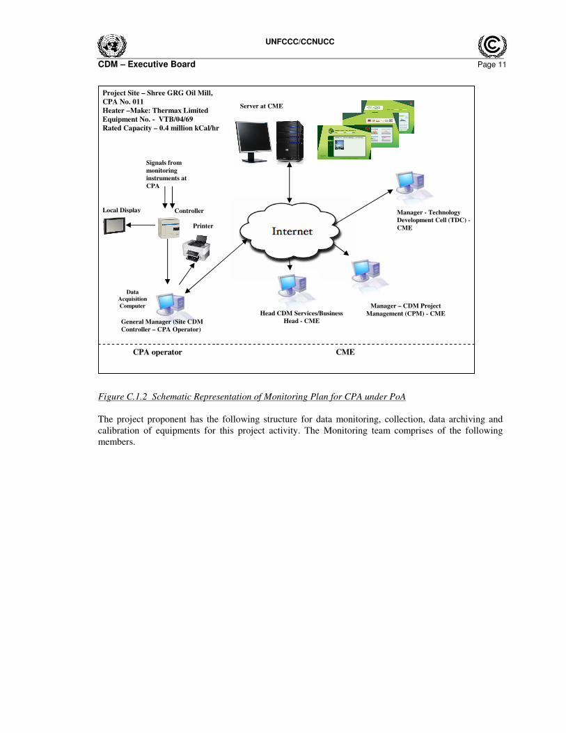
Figure C.1.2 Schematic Representation of Monitoring Plan for CPA under PoA
The project proponent has the following structure for data monitoring, collection, data archiving and
calibration of equipments for this project activity. The Monitoring team comprises of the following
members.
Server at CME
Controller
Data
Acquisition
Computer
Local Display
Manager – CDM Project
Management (CPM) - CME
Manager - Technology
Development Cell (TDC) -
CME
Head CDM Services/Business
Head - CME
Project Site – Shree GRG Oil Mill,
CPA No. 011
Heater –Make: Thermax Limited
Equipment No. - VTB/04/69
Rated Capacity – 0.4 million kCal/hr
General Manager (Site CDM
Controller – CPA Operator)
Signals from
monitoring
instruments at
CPA
Printer
CPA operator CME
UNFCCC/CCNUCC
CDM – Executive Board Page 12
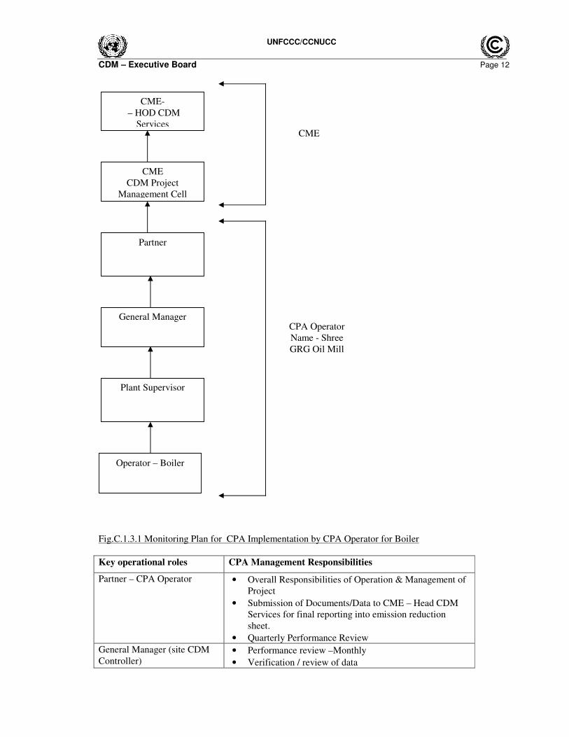
Fig.C.1.3.1 Monitoring Plan for CPA Implementation by CPA Operator for Boiler
Key operational roles CPA Management Responsibilities
Partner – CPA Operator
• Overall Responsibilities of Operation & Management of
Project
• Submission of Documents/Data to CME – Head CDM
Services for final reporting into emission reduction
sheet.
• Quarterly Performance Review
General Manager (site CDM
Controller) • Performance review –Monthly
• Verification / review of data
General Manager
Partner
Plant Supervisor
Operator – Boiler
CME-
– HOD CDM
Services
CME
CDM Project
Management Cell
CME
CPA Operator
Name - Shree
GRG Oil Mill

UNFCCC/CCNUCC
CDM – Executive Board Page 13
• Internal audits
• Review of corrective actions
Plant Supervisor • Verifying & Archiving the data
• Checking of monitored data
• Calibration of key monitoring equipment
• Maintenance of key monitoring equipment
• Implementation of corrective action
Operator – Boiler
• Operation and maintenance of boiler
• Recording/Collection of Data
• Daily Logbook data maintenance
UNFCCC/CCNUCC
CDM – Executive Board Page 14
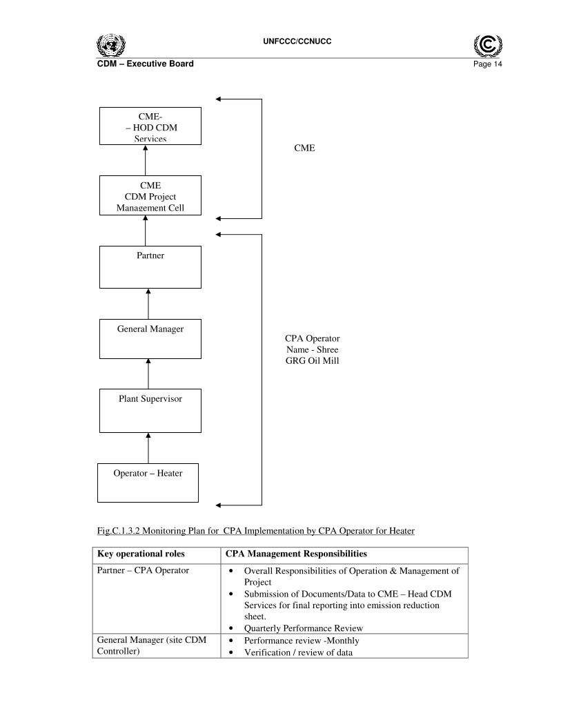
Fig.C.1.3.2 Monitoring Plan for CPA Implementation by CPA Operator for Heater
Key operational roles CPA Management Responsibilities
Partner – CPA Operator
• Overall Responsibilities of Operation & Management of
Project
• Submission of Documents/Data to CME – Head CDM
Services for final reporting into emission reduction
sheet.
• Quarterly Performance Review
General Manager (site CDM
Controller) • Performance review -Monthly
• Verification / review of data
General Manager
Partner
Plant Supervisor
Operator – Heater
CME-
– HOD CDM
Services
CME
CDM Project
Management Cell
CME
CPA Operator
Name - Shree
GRG Oil Mill
UNFCCC/CCNUCC
CDM – Executive Board Page 15
• Internal audits
• Review of corrective actions
Plant Supervisor • Verifying & Archiving the data
• Checking of monitored data
• Calibration of key monitoring equipment
• Maintenance of key monitoring equipment
• Implementation of corrective action
Operator – Heater
• Operation and maintenance of heater
• Recording/Collection of Data
• Daily Logbook data maintenance
3) Emergency Preparedness Plan: Boiler & Heater Monitoring Data Collection and Archiving:
This plan is prepared in case of partial or total monitoring system failure:
a) Emergency Preparedness Plan for Boiler:
i) Steam flow measurement system failure:
In case of Steam flow measurement system failure, the thermal energy supplied by the Project activity
will be estimated based on the most conservative approach theoretically possible.
ii) Failure of RTD/ Temperature Transmitter:
In case of failure of the RTD/ Temp Transmitter, the boiler operational staff (CPA operator) will
manually record the reading on hourly basis in the log book from the temperature gauge already installed
on feed water/steam line of the boiler. The temperature gauge shall be calibrated as per local/national
standard or as per manufacturer’s specifications. If local/national standards and manufacturer’s
specification is not available, it will be as per international standard, but at least once in 3 years.
Calibration will be carried out by independent accredited third party entity
iii) Failure of Pressure Transmitter:
For pressure transmitter failure, the pressure shall be manually noted from the installed pressure gauges
already provided which shall be considered for calculation of emission reduction. The pressure gauge
shall be calibrated as per local/national standard or as per manufacturer’s specifications. If local/national
standards and manufacturer’s specification is not available, it will be as per international standard, but at
least once in 3 years. Calibration shall be carried out by independent accredited third party entity
iv) Failure of Energy Meter:
In case of failure of energy meter, the CPA operator will record the failure period of the energy meter.
The energy (kWh) consumed in the absence of meter will be calculated considering failure hours and the
auxiliary electrical connected load of the boiler i.e. Failure hours*Electrical connected load*Grid/Diesel
Generator (DG) emission factor. The time lost in the meter correction / replacement will be recorded in
log book and this shall be used for emission reduction calculation.
UNFCCC/CCNUCC
CDM – Executive Board Page 16
b) Emergency Preparedness Plan for Heater:
i) Heat flow measurement system failure:
In case of heat flow measurement system failure, the heat will be estimated based on the most
conservative approach theoretically possible.
ii) Failure of Temperature sensors:
In case of failure of the RTD/ Temp Transmitter, the heater operational staff (CPA operator) will
manually record the reading on hourly basis in the log book from the temperature gauge already installed
on inlet and outlet line of the heater. The temperature gauge shall be calibrated as per local/national
standard or as per manufacturer’s specifications. If local/national standards and manufacturer’s
specification is not available, it will be as per international standard, but at least once in 3 years.
Calibration will be carried out by independent accredited third party entity
iii) Failure of Energy Meter:
In case of failure of energy meter, the CPA operator will record the failure period of the energy meter.
The energy (kWh) consumed in the absence of meter will be calculated considering failure hours and the
auxiliary electrical connected load of the heater i. e. Failure hours*Electrical connected
load*Grid/Diesel Generator (DG) emission factor.
The time lost in the meter correction / replacement will be recorded in log book and this shall be used
for emission reduction calculation.
4) No data transfer to CME’s server or Hardware, Software failure at Project Site:
In this case, Project site will continue to record the data automatically. CPA Operator will copy the
locally archived data and send it to CME.
During this monitoring period there was no any partial or total monitoring system failure occurred.
SECTION D. Data and Parameters
D.1. Data and parameters fixed ex ante or at renewal of crediting period
Data/Parameter CAPboiler
Unit Tons/hr
Description Rated capacity (thermal output) of the boiler of the Project activity.
Source of data Manufacturer’s specification
Value(s) applied 8 (value applicable for the Project activity as per CPA 010)
Purpose of data Baseline Emission calculation
Additional comment This data will be archived up to 2 years after the completion of crediting
period or last issuance whichever is later.
UNFCCC/CCNUCC
CDM – Executive Board Page 17
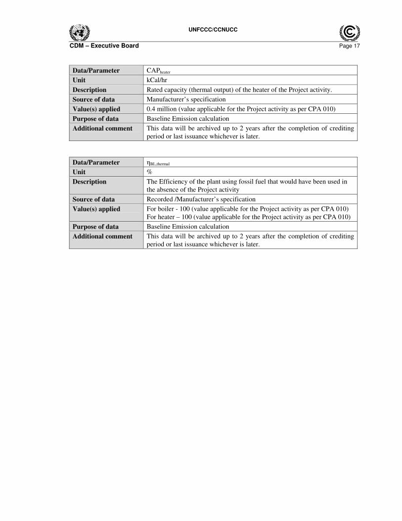
Data/Parameter CAPheater
Unit kCal/hr
Description Rated capacity (thermal output) of the heater of the Project activity.
Source of data Manufacturer’s specification
Value(s) applied 0.4 million (value applicable for the Project activity as per CPA 010)
Purpose of data Baseline Emission calculation
Additional comment This data will be archived up to 2 years after the completion of crediting
period or last issuance whichever is later.
Data/Parameter ηBL,thermal
Unit %
Description The Efficiency of the plant using fossil fuel that would have been used in
the absence of the Project activity
Source of data Recorded /Manufacturer’s specification
Value(s) applied For boiler - 100 (value applicable for the Project activity as per CPA 010)
For heater – 100 (value applicable for the Project activity as per CPA 010)
Purpose of data Baseline Emission calculation
Additional comment This data will be archived up to 2 years after the completion of crediting
period or last issuance whichever is later.
UNFCCC/CCNUCC
CDM – Executive Board Page 18
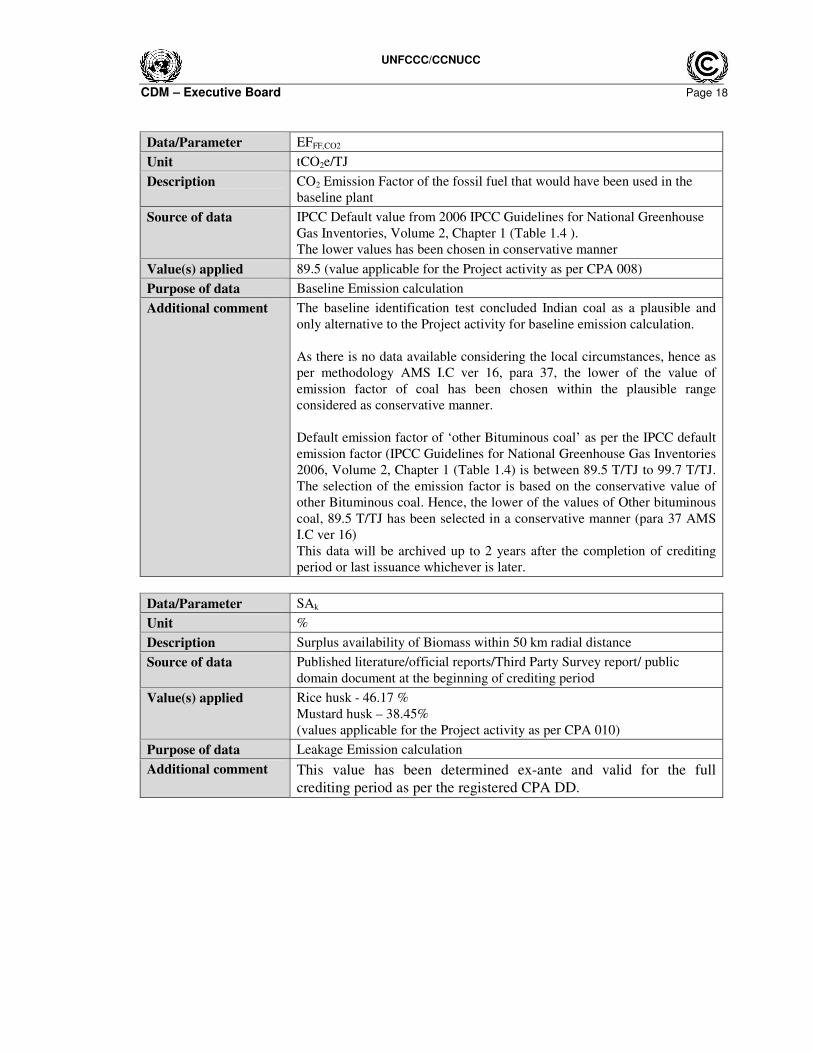
Data/Parameter EFFF,CO2
Unit tCO2e/TJ
Description CO2 Emission Factor of the fossil fuel that would have been used in the
baseline plant
Source of data IPCC Default value from 2006 IPCC Guidelines for National Greenhouse
Gas Inventories, Volume 2, Chapter 1 (Table 1.4 ).
The lower values has been chosen in conservative manner
Value(s) applied 89.5 (value applicable for the Project activity as per CPA 008)
Purpose of data Baseline Emission calculation
Additional comment The baseline identification test concluded Indian coal as a plausible and
only alternative to the Project activity for baseline emission calculation.
As there is no data available considering the local circumstances, hence as
per methodology AMS I.C ver 16, para 37, the lower of the value of
emission factor of coal has been chosen within the plausible range
considered as conservative manner.
Default emission factor of ‘other Bituminous coal’ as per the IPCC default
emission factor (IPCC Guidelines for National Greenhouse Gas Inventories
2006, Volume 2, Chapter 1 (Table 1.4) is between 89.5 T/TJ to 99.7 T/TJ.
The selection of the emission factor is based on the conservative value of
other Bituminous coal. Hence, the lower of the values of Other bituminous
coal, 89.5 T/TJ has been selected in a conservative manner (para 37 AMS
I.C ver 16)
This data will be archived up to 2 years after the completion of crediting
period or last issuance whichever is later.
Data/Parameter SAk
Unit %
Description Surplus availability of Biomass within 50 km radial distance
Source of data Published literature/official reports/Third Party Survey report/ public
domain document at the beginning of crediting period
Value(s) applied Rice husk - 46.17 %
Mustard husk – 38.45%
(values applicable for the Project activity as per CPA 010)
Purpose of data Leakage Emission calculation
Additional comment This value has been determined ex-ante and valid for the full
crediting period as per the registered CPA DD.
UNFCCC/CCNUCC
CDM – Executive Board Page 19
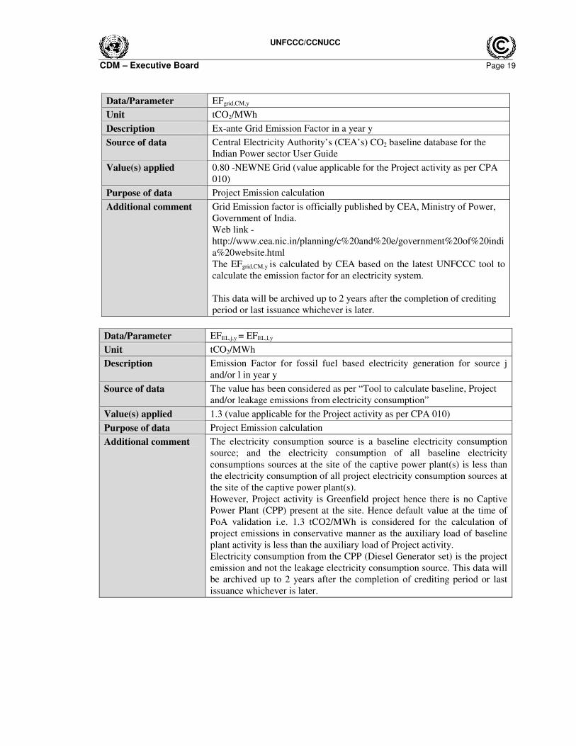
Data/Parameter EFgrid,CM,y
Unit tCO2/MWh
Description Ex-ante Grid Emission Factor in a year y
Source of data Central Electricity Authority’s (CEA’s) CO2 baseline database for the
Indian Power sector User Guide
Value(s) applied 0.80 -NEWNE Grid (value applicable for the Project activity as per CPA
010)
Purpose of data Project Emission calculation
Additional comment Grid Emission factor is officially published by CEA, Ministry of Power,
Government of India.
Web link -
http://www.cea.nic.in/planning/c%20and%20e/government%20of%20indi
a%20website.html
The EFgrid,CM,y is calculated by CEA based on the latest UNFCCC tool to
calculate the emission factor for an electricity system.
This data will be archived up to 2 years after the completion of crediting
period or last issuance whichever is later.
Data/Parameter EFEL,j,y = EFEL,l,y
Unit tCO2/MWh
Description Emission Factor for fossil fuel based electricity generation for source j
and/or l in year y
Source of data The value has been considered as per “Tool to calculate baseline, Project
and/or leakage emissions from electricity consumption”
Value(s) applied 1.3 (value applicable for the Project activity as per CPA 010)
Purpose of data Project Emission calculation
Additional comment The electricity consumption source is a baseline electricity consumption
source; and the electricity consumption of all baseline electricity
consumptions sources at the site of the captive power plant(s) is less than
the electricity consumption of all project electricity consumption sources at
the site of the captive power plant(s).
However, Project activity is Greenfield project hence there is no Captive
Power Plant (CPP) present at the site. Hence default value at the time of
PoA validation i.e. 1.3 tCO2/MWh is considered for the calculation of
project emissions in conservative manner as the auxiliary load of baseline
plant activity is less than the auxiliary load of Project activity.
Electricity consumption from the CPP (Diesel Generator set) is the project
emission and not the leakage electricity consumption source. This data will
be archived up to 2 years after the completion of crediting period or last
issuance whichever is later.
UNFCCC/CCNUCC
CDM – Executive Board Page 20
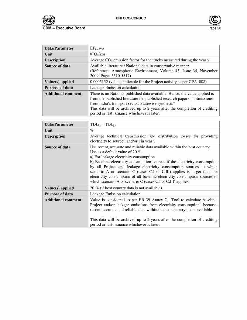
Data/Parameter EFkm,CO2
Unit tCO2/km
Description Average CO2 emission factor for the trucks measured during the year y
Source of data Available literature / National data in conservative manner
(Reference: Atmospheric Environment, Volume 43, Issue 34, November
2009, Pages 5510-5517)
Value(s) applied 0.0005152 (value applicable for the Project activity as per CPA 008)
Purpose of data Leakage Emission calculation
Additional comment There is no National published data available. Hence, the value applied is
from the published literature i.e. published research paper on “Emissions
from India’s transport sector: Statewise synthesis”
This data will be archived up to 2 years after the completion of crediting
period or last issuance whichever is later.
Data/Parameter TDLl,y = TDLj,y
Unit %
Description Average technical transmission and distribution losses for providing
electricity to source l and/or j in year y
Source of data Use recent, accurate and reliable data available within the host country;
Use as a default value of 20 % ,
a) For leakage electricity consumption.
b) Baseline electricity consumption sources if the electricity consumption
by all Project and leakage electricity consumption sources to which
scenario A or scenario C (cases C.I or C.III) applies is larger than the
electricity consumption of all baseline electricity consumption sources to
which scenario A or scenario C (cases C.I or C.III) applies
Value(s) applied 20 % (if host country data is not available)
Purpose of data Leakage Emission calculation
Additional comment Value is considered as per EB 39 Annex 7, “Tool to calculate baseline,
Project and/or leakage emissions from electricity consumption” because,
recent, accurate and reliable data within the host country is not available.
This data will be archived up to 2 years after the completion of crediting
period or last issuance whichever is later.
UNFCCC/CCNUCC
CDM – Executive Board Page 21
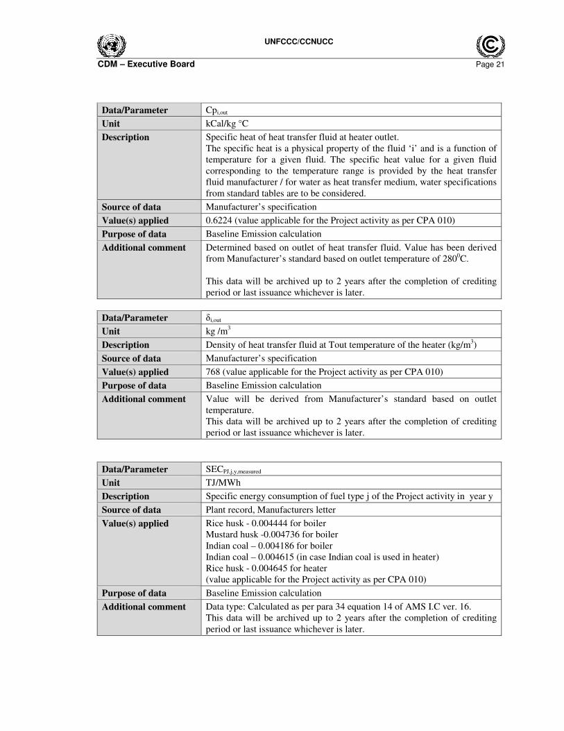
Data/Parameter Cpi,out
Unit kCal/kg °C
Description Specific heat of heat transfer fluid at heater outlet.
The specific heat is a physical property of the fluid ‘i’ and is a function of
temperature for a given fluid. The specific heat value for a given fluid
corresponding to the temperature range is provided by the heat transfer
fluid manufacturer / for water as heat transfer medium, water specifications
from standard tables are to be considered.
Source of data Manufacturer’s specification
Value(s) applied 0.6224 (value applicable for the Project activity as per CPA 010)
Purpose of data Baseline Emission calculation
Additional comment Determined based on outlet of heat transfer fluid. Value has been derived
from Manufacturer’s standard based on outlet temperature of 2800C.
This data will be archived up to 2 years after the completion of crediting
period or last issuance whichever is later.
Data/Parameter δi,out
Unit kg /m3
Description Density of heat transfer fluid at Tout temperature of the heater (kg/m3)
Source of data Manufacturer’s specification
Value(s) applied 768 (value applicable for the Project activity as per CPA 010)
Purpose of data Baseline Emission calculation
Additional comment Value will be derived from Manufacturer’s standard based on outlet
temperature.
This data will be archived up to 2 years after the completion of crediting
period or last issuance whichever is later.
Data/Parameter SECPJ,j,y,measured
Unit TJ/MWh
Description Specific energy consumption of fuel type j of the Project activity in year y
Source of data Plant record, Manufacturers letter
Value(s) applied Rice husk - 0.004444 for boiler
Mustard husk -0.004736 for boiler
Indian coal – 0.004186 for boiler
Indian coal – 0.004615 (in case Indian coal is used in heater)
Rice husk - 0.004645 for heater
(value applicable for the Project activity as per CPA 010)
Purpose of data Baseline Emission calculation
Additional comment Data type: Calculated as per para 34 equation 14 of AMS I.C ver. 16.
This data will be archived up to 2 years after the completion of crediting
period or last issuance whichever is later.
UNFCCC/CCNUCC
CDM – Executive Board Page 22
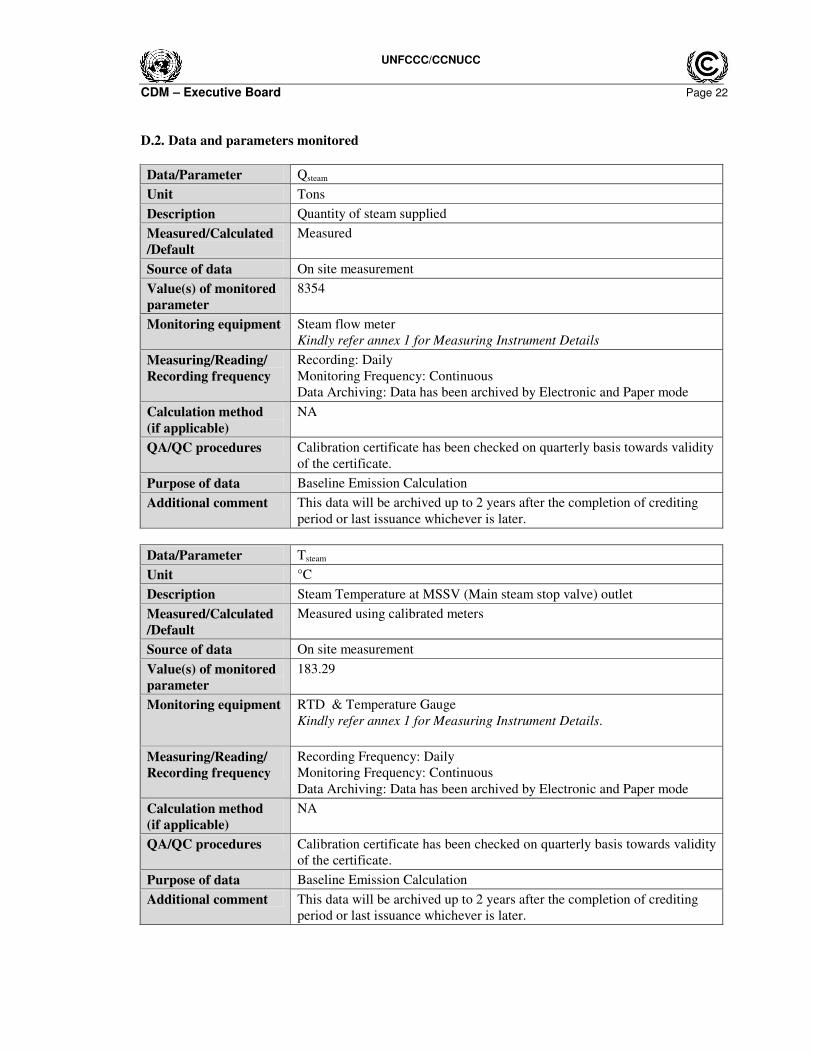
D.2. Data and parameters monitored
Data/Parameter Qsteam
Unit Tons
Description Quantity of steam supplied
Measured/Calculated
/Default
Measured
Source of data On site measurement
Value(s) of monitored
parameter
8354
Monitoring equipment Steam flow meter
Kindly refer annex 1 for Measuring Instrument Details
Measuring/Reading/
Recording frequency
Recording: Daily
Monitoring Frequency: Continuous
Data Archiving: Data has been archived by Electronic and Paper mode
Calculation method
(if applicable)
NA
QA/QC procedures Calibration certificate has been checked on quarterly basis towards validity
of the certificate.
Purpose of data Baseline Emission Calculation
Additional comment This data will be archived up to 2 years after the completion of crediting
period or last issuance whichever is later.
Data/Parameter Tsteam
Unit °C
Description Steam Temperature at MSSV (Main steam stop valve) outlet
Measured/Calculated
/Default
Measured using calibrated meters
Source of data On site measurement
Value(s) of monitored
parameter
183.29
Monitoring equipment RTD & Temperature Gauge
Kindly refer annex 1 for Measuring Instrument Details.
Measuring/Reading/
Recording frequency
Recording Frequency: Daily
Monitoring Frequency: Continuous
Data Archiving: Data has been archived by Electronic and Paper mode
Calculation method
(if applicable)
NA
QA/QC procedures Calibration certificate has been checked on quarterly basis towards validity
of the certificate.
Purpose of data Baseline Emission Calculation
Additional comment This data will be archived up to 2 years after the completion of crediting
period or last issuance whichever is later.
UNFCCC/CCNUCC
CDM – Executive Board Page 23
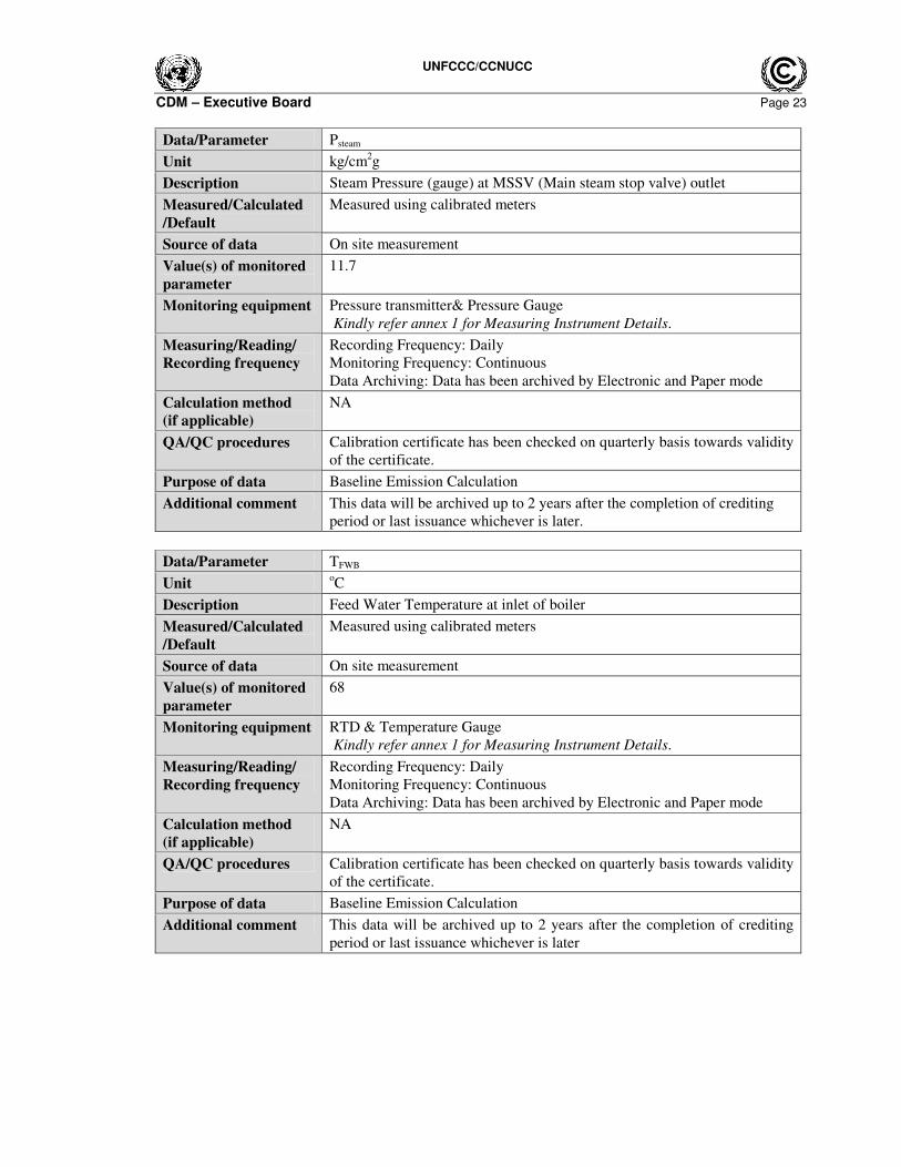
Data/Parameter Psteam
Unit kg/cm2g
Description Steam Pressure (gauge) at MSSV (Main steam stop valve) outlet
Measured/Calculated
/Default
Measured using calibrated meters
Source of data On site measurement
Value(s) of monitored
parameter
11.7
Monitoring equipment Pressure transmitter& Pressure Gauge
Kindly refer annex 1 for Measuring Instrument Details.
Measuring/Reading/
Recording frequency
Recording Frequency: Daily
Monitoring Frequency: Continuous
Data Archiving: Data has been archived by Electronic and Paper mode
Calculation method
(if applicable)
NA
QA/QC procedures Calibration certificate has been checked on quarterly basis towards validity
of the certificate.
Purpose of data Baseline Emission Calculation
Additional comment This data will be archived up to 2 years after the completion of crediting
period or last issuance whichever is later.
Data/Parameter TFWB
Unit oC
Description Feed Water Temperature at inlet of boiler
Measured/Calculated
/Default
Measured using calibrated meters
Source of data On site measurement
Value(s) of monitored
parameter
68
Monitoring equipment RTD & Temperature Gauge
Kindly refer annex 1 for Measuring Instrument Details.
Measuring/Reading/
Recording frequency
Recording Frequency: Daily
Monitoring Frequency: Continuous
Data Archiving: Data has been archived by Electronic and Paper mode
Calculation method
(if applicable)
NA
QA/QC procedures Calibration certificate has been checked on quarterly basis towards validity
of the certificate.
Purpose of data Baseline Emission Calculation
Additional comment This data will be archived up to 2 years after the completion of crediting
period or last issuance whichever is later
UNFCCC/CCNUCC
CDM – Executive Board Page 24
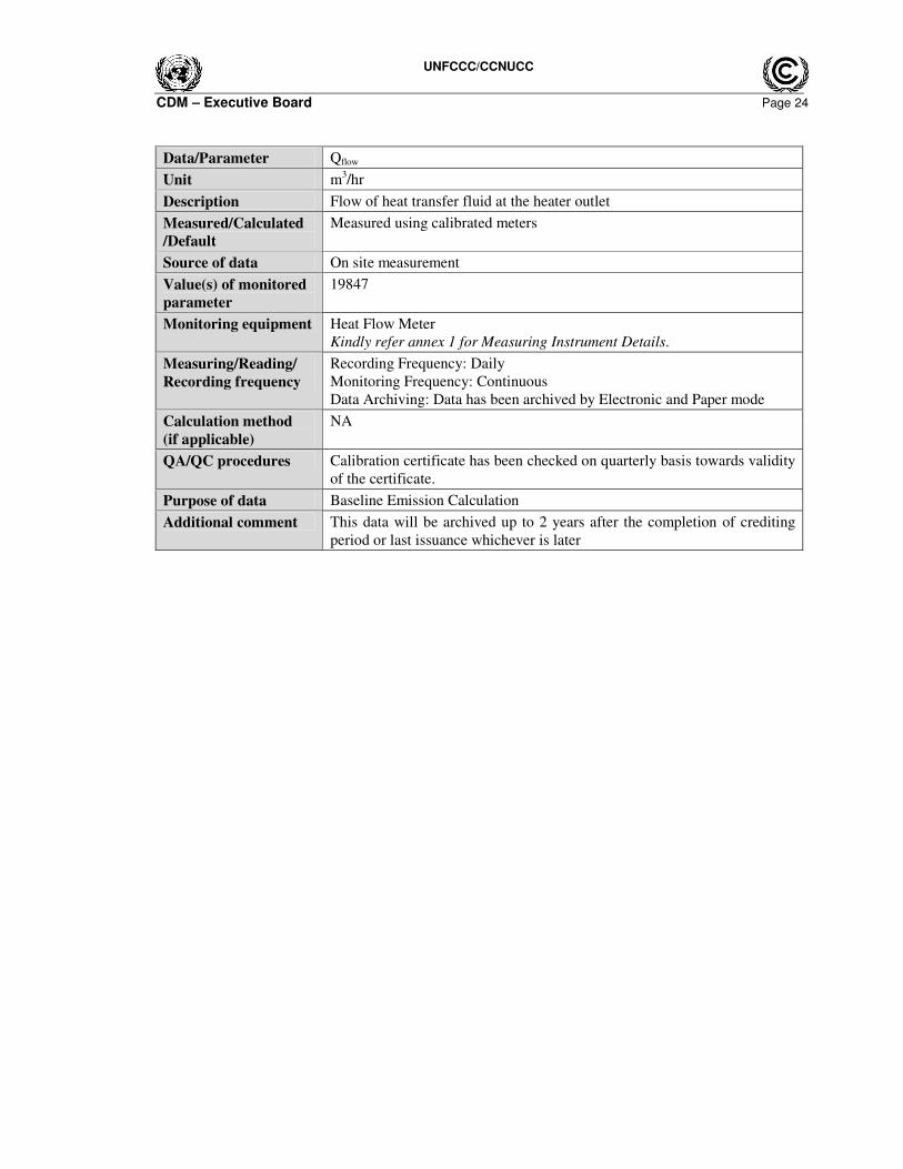
Data/Parameter Qflow
Unit m3/hr
Description Flow of heat transfer fluid at the heater outlet
Measured/Calculated
/Default
Measured using calibrated meters
Source of data On site measurement
Value(s) of monitored
parameter
19847
Monitoring equipment Heat Flow Meter
Kindly refer annex 1 for Measuring Instrument Details.
Measuring/Reading/
Recording frequency
Recording Frequency: Daily
Monitoring Frequency: Continuous
Data Archiving: Data has been archived by Electronic and Paper mode
Calculation method
(if applicable)
NA
QA/QC procedures Calibration certificate has been checked on quarterly basis towards validity
of the certificate.
Purpose of data Baseline Emission Calculation
Additional comment This data will be archived up to 2 years after the completion of crediting
period or last issuance whichever is later
UNFCCC/CCNUCC
CDM – Executive Board Page 25
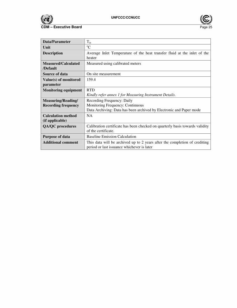
Data/Parameter Tin
Unit oC
Description Average Inlet Temperature of the heat transfer fluid at the inlet of the
heater
Measured/Calculated
/Default
Measured using calibrated meters
Source of data On site measurement
Value(s) of monitored
parameter
159.4
Monitoring equipment RTD
Kindly refer annex 1 for Measuring Instrument Details.
Measuring/Reading/
Recording frequency
Recording Frequency: Daily
Monitoring Frequency: Continuous
Data Archiving: Data has been archived by Electronic and Paper mode
Calculation method
(if applicable)
NA
QA/QC procedures Calibration certificate has been checked on quarterly basis towards validity
of the certificate.
Purpose of data Baseline Emission Calculation
Additional comment This data will be archived up to 2 years after the completion of crediting
period or last issuance whichever is later
UNFCCC/CCNUCC
CDM – Executive Board Page 26
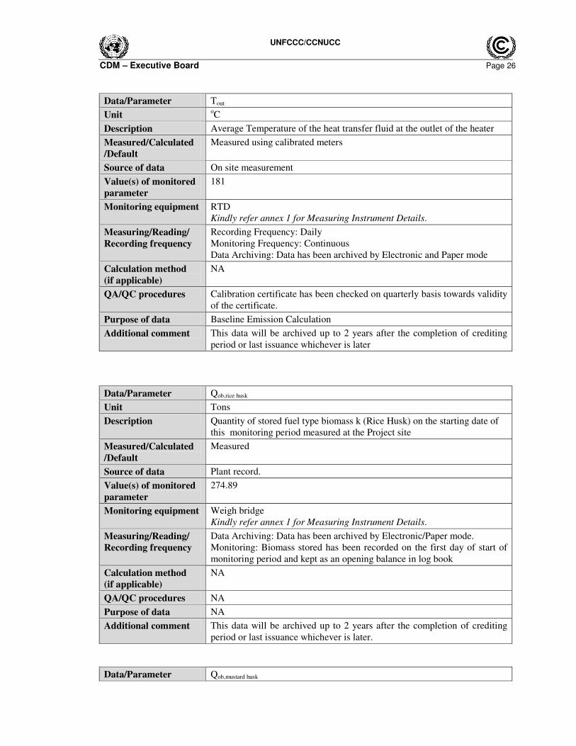
Data/Parameter Tout
Unit oC
Description Average Temperature of the heat transfer fluid at the outlet of the heater
Measured/Calculated
/Default
Measured using calibrated meters
Source of data On site measurement
Value(s) of monitored
parameter
181
Monitoring equipment RTD
Kindly refer annex 1 for Measuring Instrument Details.
Measuring/Reading/
Recording frequency
Recording Frequency: Daily
Monitoring Frequency: Continuous
Data Archiving: Data has been archived by Electronic and Paper mode
Calculation method
(if applicable)
NA
QA/QC procedures Calibration certificate has been checked on quarterly basis towards validity
of the certificate.
Purpose of data Baseline Emission Calculation
Additional comment This data will be archived up to 2 years after the completion of crediting
period or last issuance whichever is later
Data/Parameter Qob,rice husk
Unit Tons
Description Quantity of stored fuel type biomass k (Rice Husk) on the starting date of
this monitoring period measured at the Project site
Measured/Calculated
/Default
Measured
Source of data Plant record.
Value(s) of monitored
parameter
274.89
Monitoring equipment Weigh bridge
Kindly refer annex 1 for Measuring Instrument Details.
Measuring/Reading/
Recording frequency
Data Archiving: Data has been archived by Electronic/Paper mode.
Monitoring: Biomass stored has been recorded on the first day of start of
monitoring period and kept as an opening balance in log book
Calculation method
(if applicable)
NA
QA/QC procedures NA
Purpose of data NA
Additional comment This data will be archived up to 2 years after the completion of crediting
period or last issuance whichever is later.
Data/Parameter Qob,mustard husk

UNFCCC/CCNUCC
CDM – Executive Board Page 27
Unit Tons
Description Quantity of stored fuel type biomass k (Mustard Husk) on the starting date
of this monitoring period measured at the Project site
Measured/Calculated
/Default
Measured
Source of data Plant record.
Value(s) of monitored
parameter
1202.59
Monitoring equipment Weigh bridge
Kindly refer annex 1 for Measuring Instrument Details.
Measuring/Reading/
Recording frequency
Data Archiving: Data has been archived by Electronic and Paper mode.
Monitoring: Biomass stored has been recorded on the first day of start of
monitoring period and kept as an opening balance in log book
Calculation method
(if applicable)
NA
QA/QC procedures NA
Purpose of data NA
Additional comment This data will be archived up to 2 years after the completion of crediting
period or last issuance whichever is later.
Data/Parameter Qnp, rice husk
Unit Tons
Description Quantity of subsequent delivery of fuel type k (Rice Husk) biomass at the
Project site
Measured/Calculated
/Default
Measured
Source of data Weigh bridge slip and Plant record.
Value(s) of monitored
parameter
0
Monitoring equipment Weigh bridge
Kindly refer annex 1 for Measuring Instrument Details.
Measuring/Reading/
Recording frequency
Data Archiving: Data has been archived by Electronic and Paper mode.
Monitoring: Biomass delivery note obtained from the fuel supplier.
Calculation method
(if applicable)
NA
QA/QC procedures NA
Purpose of data NA
Additional comment CPA operator has not procured the rice husk during this monitoring period
hence value has mentioned not applicable. This data will be archived up to
2 years after the completion of crediting period or last issuance whichever
is later.
UNFCCC/CCNUCC
CDM – Executive Board Page 28
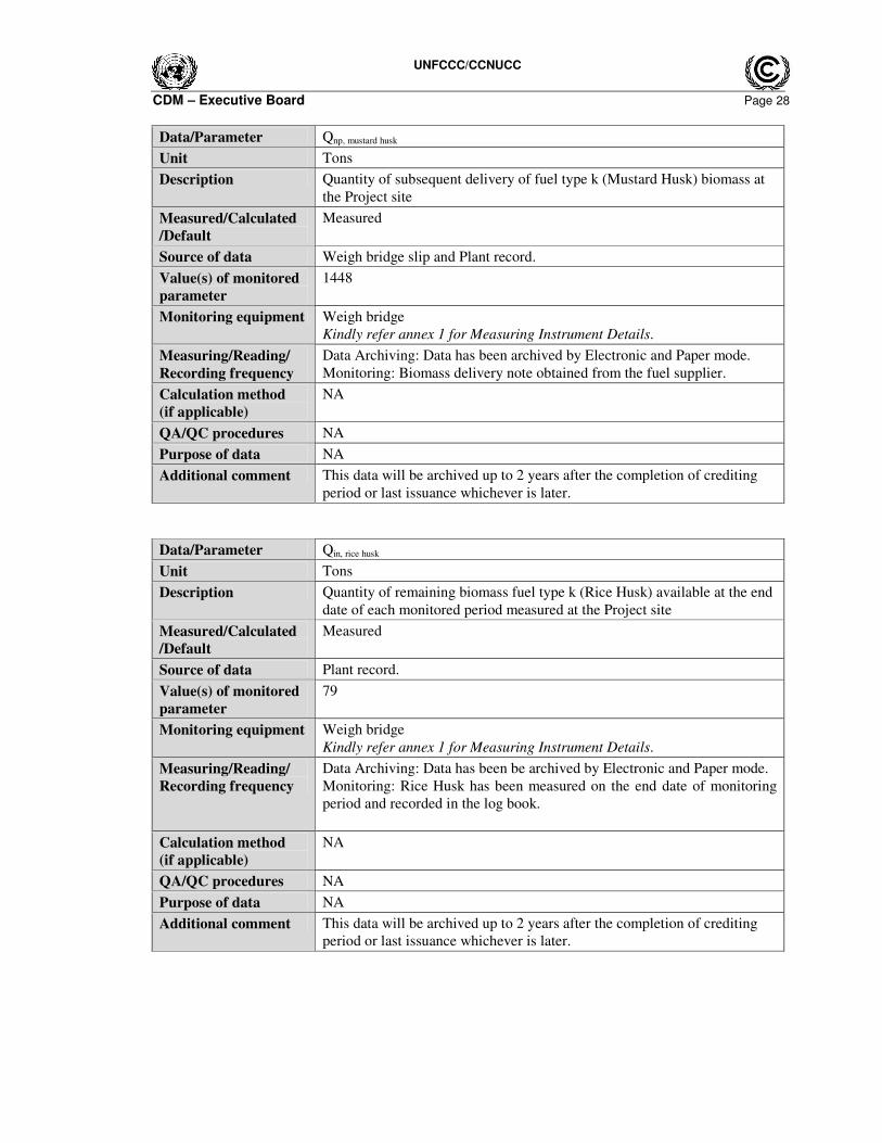
Data/Parameter Qnp, mustard husk
Unit Tons
Description Quantity of subsequent delivery of fuel type k (Mustard Husk) biomass at
the Project site
Measured/Calculated
/Default
Measured
Source of data Weigh bridge slip and Plant record.
Value(s) of monitored
parameter
1448
Monitoring equipment Weigh bridge
Kindly refer annex 1 for Measuring Instrument Details.
Measuring/Reading/
Recording frequency
Data Archiving: Data has been archived by Electronic and Paper mode.
Monitoring: Biomass delivery note obtained from the fuel supplier.
Calculation method
(if applicable)
NA
QA/QC procedures NA
Purpose of data NA
Additional comment This data will be archived up to 2 years after the completion of crediting
period or last issuance whichever is later.
Data/Parameter Qin, rice husk
Unit Tons
Description Quantity of remaining biomass fuel type k (Rice Husk) available at the end
date of each monitored period measured at the Project site
Measured/Calculated
/Default
Measured
Source of data Plant record.
Value(s) of monitored
parameter
79
Monitoring equipment Weigh bridge
Kindly refer annex 1 for Measuring Instrument Details.
Measuring/Reading/
Recording frequency
Data Archiving: Data has been be archived by Electronic and Paper mode.
Monitoring: Rice Husk has been measured on the end date of monitoring
period and recorded in the log book.
Calculation method
(if applicable)
NA
QA/QC procedures NA
Purpose of data NA
Additional comment This data will be archived up to 2 years after the completion of crediting
period or last issuance whichever is later.
UNFCCC/CCNUCC
CDM – Executive Board Page 29
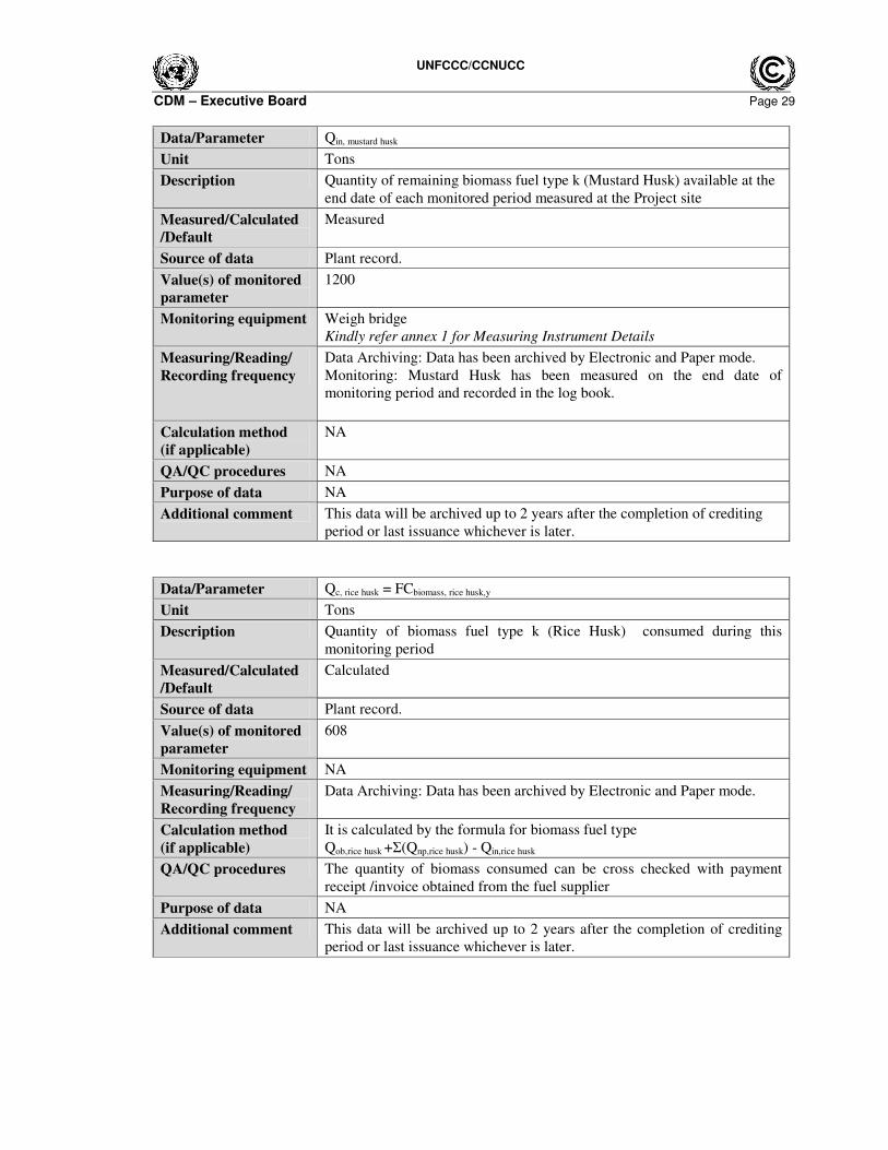
Data/Parameter Qin, mustard husk
Unit Tons
Description Quantity of remaining biomass fuel type k (Mustard Husk) available at the
end date of each monitored period measured at the Project site
Measured/Calculated
/Default
Measured
Source of data Plant record.
Value(s) of monitored
parameter
1200
Monitoring equipment Weigh bridge
Kindly refer annex 1 for Measuring Instrument Details
Measuring/Reading/
Recording frequency
Data Archiving: Data has been archived by Electronic and Paper mode.
Monitoring: Mustard Husk has been measured on the end date of
monitoring period and recorded in the log book.
Calculation method
(if applicable)
NA
QA/QC procedures NA
Purpose of data NA
Additional comment This data will be archived up to 2 years after the completion of crediting
period or last issuance whichever is later.
Data/Parameter Qc, rice husk = FCbiomass, rice husk,y
Unit Tons
Description Quantity of biomass fuel type k (Rice Husk) consumed during this
monitoring period
Measured/Calculated
/Default
Calculated
Source of data Plant record.
Value(s) of monitored
parameter
608
Monitoring equipment NA
Measuring/Reading/
Recording frequency
Data Archiving: Data has been archived by Electronic and Paper mode.
Calculation method
(if applicable)
It is calculated by the formula for biomass fuel type
Qob,rice husk +Σ(Qnp,rice husk) - Qin,rice husk
QA/QC procedures The quantity of biomass consumed can be cross checked with payment
receipt /invoice obtained from the fuel supplier
Purpose of data NA
Additional comment This data will be archived up to 2 years after the completion of crediting
period or last issuance whichever is later.
UNFCCC/CCNUCC
CDM – Executive Board Page 30
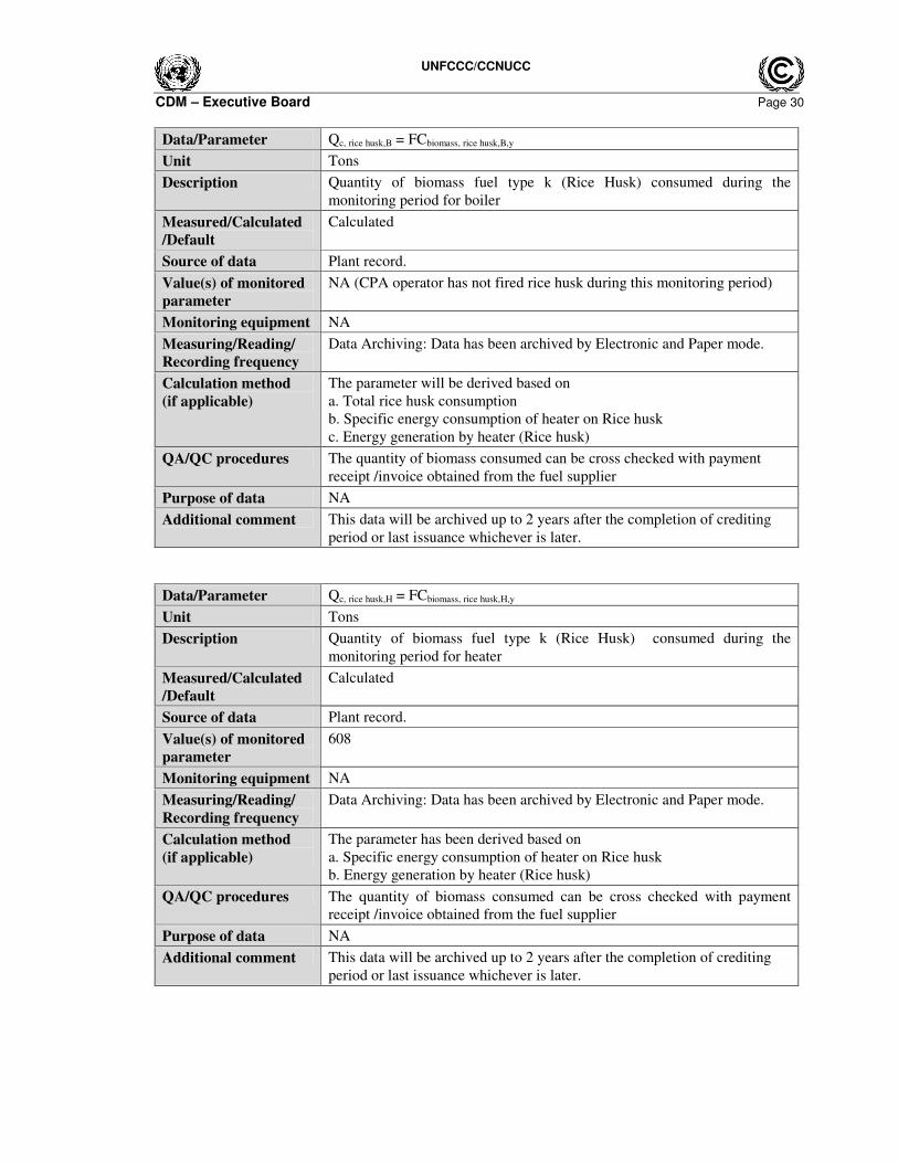
Data/Parameter Qc, rice husk,B = FCbiomass, rice husk,B,y
Unit Tons
Description Quantity of biomass fuel type k (Rice Husk) consumed during the
monitoring period for boiler
Measured/Calculated
/Default
Calculated
Source of data Plant record.
Value(s) of monitored
parameter
NA (CPA operator has not fired rice husk during this monitoring period)
Monitoring equipment NA
Measuring/Reading/
Recording frequency
Data Archiving: Data has been archived by Electronic and Paper mode.
Calculation method
(if applicable)
The parameter will be derived based on
a. Total rice husk consumption
b. Specific energy consumption of heater on Rice husk
c. Energy generation by heater (Rice husk)
QA/QC procedures The quantity of biomass consumed can be cross checked with payment
receipt /invoice obtained from the fuel supplier
Purpose of data NA
Additional comment This data will be archived up to 2 years after the completion of crediting
period or last issuance whichever is later.
Data/Parameter Qc, rice husk,H = FCbiomass, rice husk,H,y
Unit Tons
Description Quantity of biomass fuel type k (Rice Husk) consumed during the
monitoring period for heater
Measured/Calculated
/Default
Calculated
Source of data Plant record.
Value(s) of monitored
parameter
608
Monitoring equipment NA
Measuring/Reading/
Recording frequency
Data Archiving: Data has been archived by Electronic and Paper mode.
Calculation method
(if applicable)
The parameter has been derived based on
a. Specific energy consumption of heater on Rice husk
b. Energy generation by heater (Rice husk)
QA/QC procedures The quantity of biomass consumed can be cross checked with payment
receipt /invoice obtained from the fuel supplier
Purpose of data NA
Additional comment This data will be archived up to 2 years after the completion of crediting
period or last issuance whichever is later.
UNFCCC/CCNUCC
CDM – Executive Board Page 31
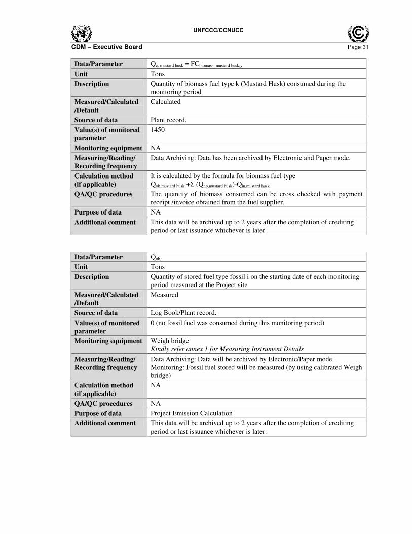
Data/Parameter Qc, mustard husk = FCbiomass, mustard husk,y
Unit Tons
Description Quantity of biomass fuel type k (Mustard Husk) consumed during the
monitoring period
Measured/Calculated
/Default
Calculated
Source of data Plant record.
Value(s) of monitored
parameter
1450
Monitoring equipment NA
Measuring/Reading/
Recording frequency
Data Archiving: Data has been archived by Electronic and Paper mode.
Calculation method
(if applicable)
It is calculated by the formula for biomass fuel type
Qob,mustard husk +Σ (Qnp,mustard husk)-Qin,mustard husk
QA/QC procedures The quantity of biomass consumed can be cross checked with payment
receipt /invoice obtained from the fuel supplier.
Purpose of data NA
Additional comment This data will be archived up to 2 years after the completion of crediting
period or last issuance whichever is later.
Data/Parameter Qob,i
Unit Tons
Description Quantity of stored fuel type fossil i on the starting date of each monitoring
period measured at the Project site
Measured/Calculated
/Default
Measured
Source of data Log Book/Plant record.
Value(s) of monitored
parameter
0 (no fossil fuel was consumed during this monitoring period)
Monitoring equipment Weigh bridge
Kindly refer annex 1 for Measuring Instrument Details
Measuring/Reading/
Recording frequency
Data Archiving: Data will be archived by Electronic/Paper mode.
Monitoring: Fossil fuel stored will be measured (by using calibrated Weigh
bridge)
Calculation method
(if applicable)
NA
QA/QC procedures NA
Purpose of data Project Emission Calculation
Additional comment This data will be archived up to 2 years after the completion of crediting
period or last issuance whichever is later.
UNFCCC/CCNUCC
CDM – Executive Board Page 32
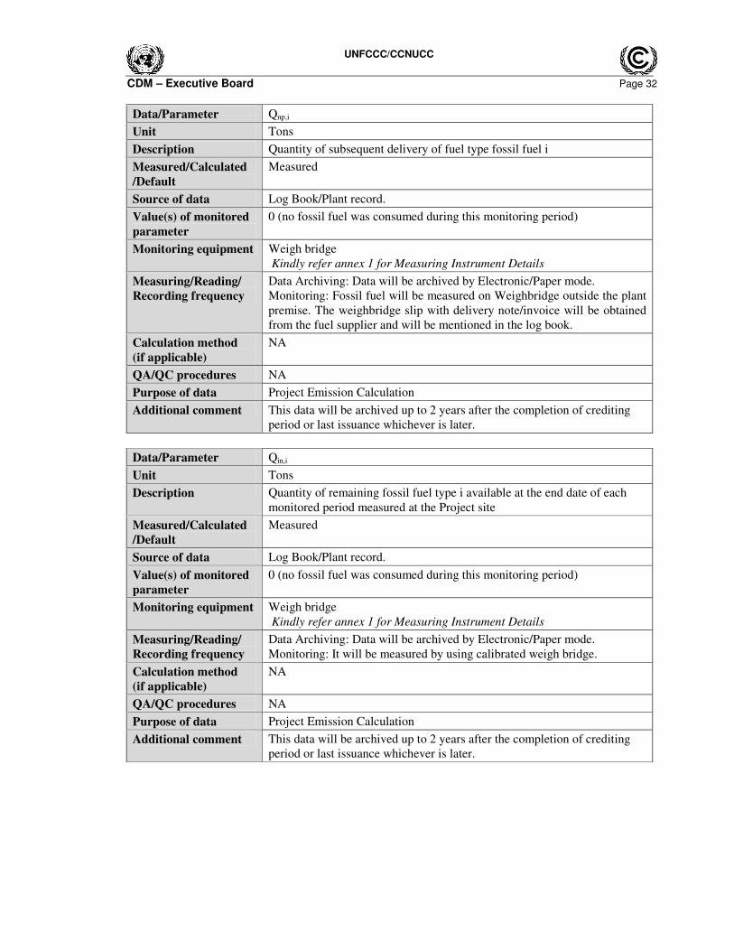
Data/Parameter Qnp,i
Unit Tons
Description Quantity of subsequent delivery of fuel type fossil fuel i
Measured/Calculated
/Default
Measured
Source of data Log Book/Plant record.
Value(s) of monitored
parameter
0 (no fossil fuel was consumed during this monitoring period)
Monitoring equipment Weigh bridge
Kindly refer annex 1 for Measuring Instrument Details
Measuring/Reading/
Recording frequency
Data Archiving: Data will be archived by Electronic/Paper mode.
Monitoring: Fossil fuel will be measured on Weighbridge outside the plant
premise. The weighbridge slip with delivery note/invoice will be obtained
from the fuel supplier and will be mentioned in the log book.
Calculation method
(if applicable)
NA
QA/QC procedures NA
Purpose of data Project Emission Calculation
Additional comment This data will be archived up to 2 years after the completion of crediting
period or last issuance whichever is later.
Data/Parameter Qin,i
Unit Tons
Description Quantity of remaining fossil fuel type i available at the end date of each
monitored period measured at the Project site
Measured/Calculated
/Default
Measured
Source of data Log Book/Plant record.
Value(s) of monitored
parameter
0 (no fossil fuel was consumed during this monitoring period)
Monitoring equipment Weigh bridge
Kindly refer annex 1 for Measuring Instrument Details
Measuring/Reading/
Recording frequency
Data Archiving: Data will be archived by Electronic/Paper mode.
Monitoring: It will be measured by using calibrated weigh bridge.
Calculation method
(if applicable)
NA
QA/QC procedures NA
Purpose of data Project Emission Calculation
Additional comment This data will be archived up to 2 years after the completion of crediting
period or last issuance whichever is later.
UNFCCC/CCNUCC
CDM – Executive Board Page 33
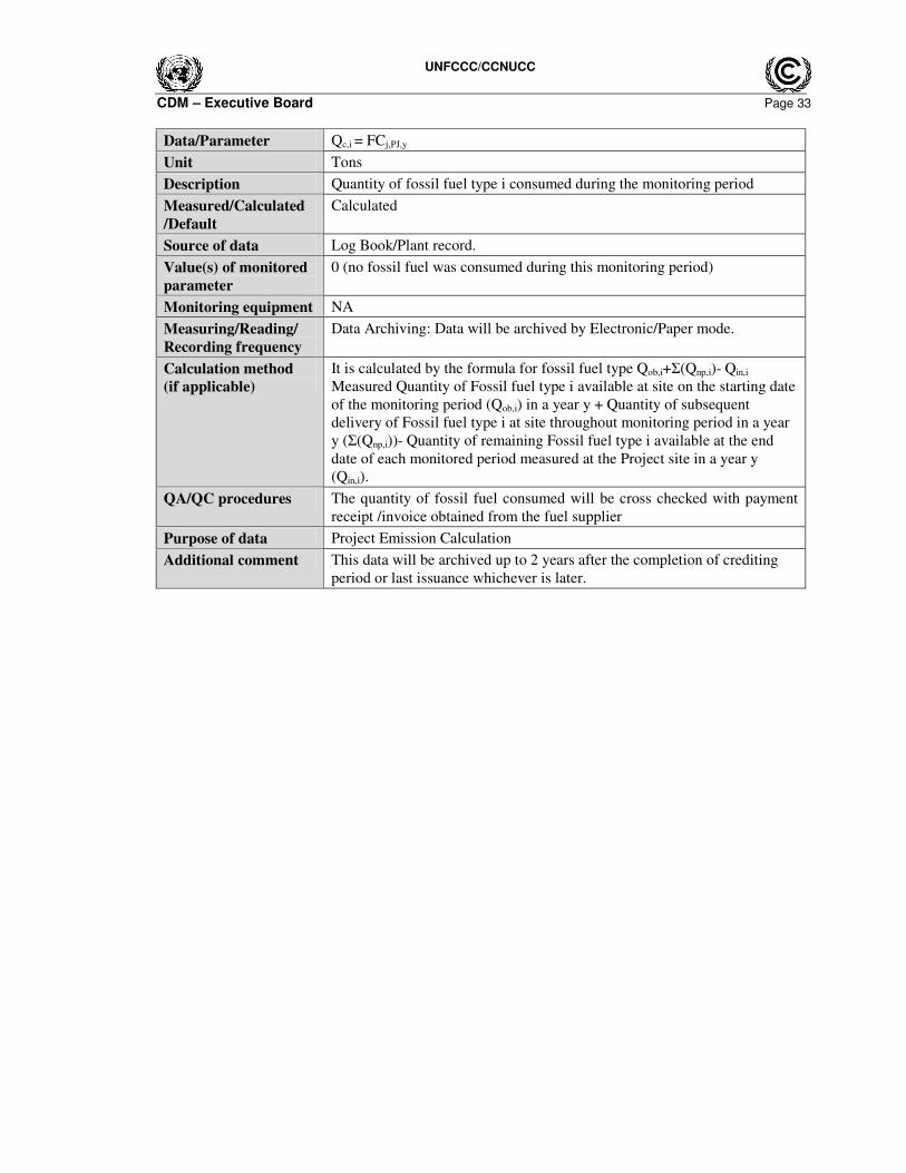
Data/Parameter Qc,i = FCj,PJ,y
Unit Tons
Description Quantity of fossil fuel type i consumed during the monitoring period
Measured/Calculated
/Default
Calculated
Source of data Log Book/Plant record.
Value(s) of monitored
parameter
0 (no fossil fuel was consumed during this monitoring period)
Monitoring equipment NA
Measuring/Reading/
Recording frequency
Data Archiving: Data will be archived by Electronic/Paper mode.
Calculation method
(if applicable)
It is calculated by the formula for fossil fuel type Qob,i+Σ(Qnp,i)- Qin,i
Measured Quantity of Fossil fuel type i available at site on the starting date
of the monitoring period (Qob,i) in a year y + Quantity of subsequent
delivery of Fossil fuel type i at site throughout monitoring period in a year
y (Σ(Qnp,i))- Quantity of remaining Fossil fuel type i available at the end
date of each monitored period measured at the Project site in a year y
(Qin,i).
QA/QC procedures The quantity of fossil fuel consumed will be cross checked with payment
receipt /invoice obtained from the fuel supplier
Purpose of data Project Emission Calculation
Additional comment This data will be archived up to 2 years after the completion of crediting
period or last issuance whichever is later.
UNFCCC/CCNUCC
CDM – Executive Board Page 34
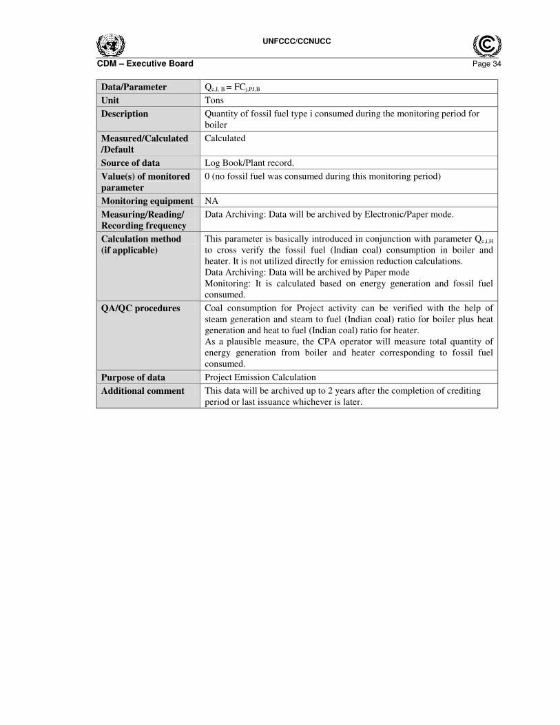
Data/Parameter Qc,I, B = FCj,PJ,B
Unit Tons
Description Quantity of fossil fuel type i consumed during the monitoring period for
boiler
Measured/Calculated
/Default
Calculated
Source of data Log Book/Plant record.
Value(s) of monitored
parameter
0 (no fossil fuel was consumed during this monitoring period)
Monitoring equipment NA
Measuring/Reading/
Recording frequency
Data Archiving: Data will be archived by Electronic/Paper mode.
Calculation method
(if applicable)
This parameter is basically introduced in conjunction with parameter Qc,i,H
to cross verify the fossil fuel (Indian coal) consumption in boiler and
heater. It is not utilized directly for emission reduction calculations.
Data Archiving: Data will be archived by Paper mode
Monitoring: It is calculated based on energy generation and fossil fuel
consumed.
QA/QC procedures Coal consumption for Project activity can be verified with the help of
steam generation and steam to fuel (Indian coal) ratio for boiler plus heat
generation and heat to fuel (Indian coal) ratio for heater.
As a plausible measure, the CPA operator will measure total quantity of
energy generation from boiler and heater corresponding to fossil fuel
consumed.
Purpose of data Project Emission Calculation
Additional comment This data will be archived up to 2 years after the completion of crediting
period or last issuance whichever is later.
UNFCCC/CCNUCC
CDM – Executive Board Page 35
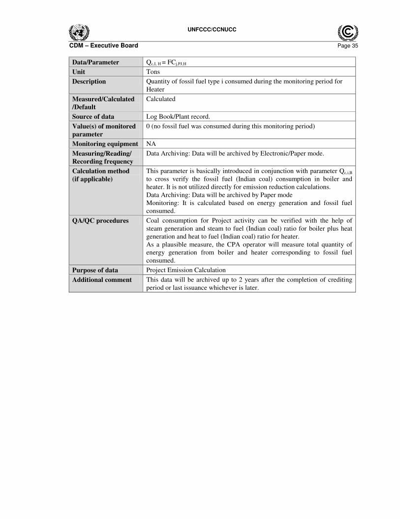
Data/Parameter Qc,I, H = FCj,PJ,H
Unit Tons
Description Quantity of fossil fuel type i consumed during the monitoring period for
Heater
Measured/Calculated
/Default
Calculated
Source of data Log Book/Plant record.
Value(s) of monitored
parameter
0 (no fossil fuel was consumed during this monitoring period)
Monitoring equipment NA
Measuring/Reading/
Recording frequency
Data Archiving: Data will be archived by Electronic/Paper mode.
Calculation method
(if applicable)
This parameter is basically introduced in conjunction with parameter Qc,i,B
to cross verify the fossil fuel (Indian coal) consumption in boiler and
heater. It is not utilized directly for emission reduction calculations.
Data Archiving: Data will be archived by Paper mode
Monitoring: It is calculated based on energy generation and fossil fuel
consumed.
QA/QC procedures Coal consumption for Project activity can be verified with the help of
steam generation and steam to fuel (Indian coal) ratio for boiler plus heat
generation and heat to fuel (Indian coal) ratio for heater.
As a plausible measure, the CPA operator will measure total quantity of
energy generation from boiler and heater corresponding to fossil fuel
consumed.
Purpose of data Project Emission Calculation
Additional comment This data will be archived up to 2 years after the completion of crediting
period or last issuance whichever is later.
UNFCCC/CCNUCC
CDM – Executive Board Page 36
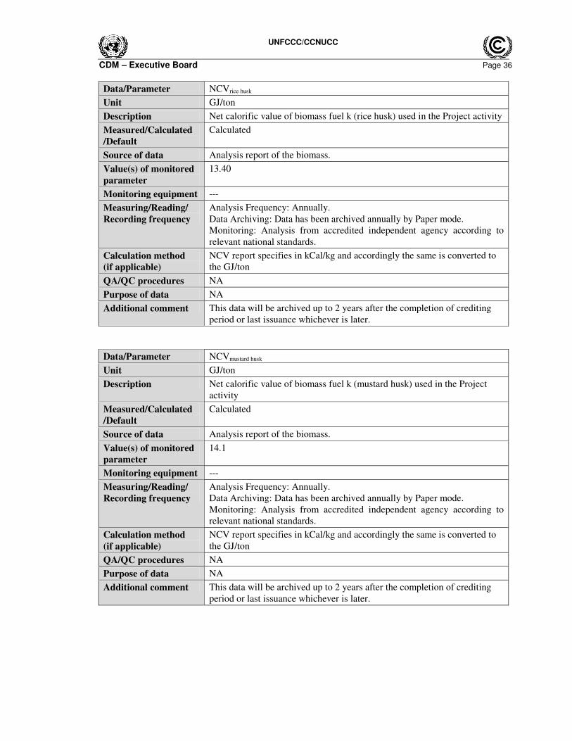
Data/Parameter NCVrice husk
Unit GJ/ton
Description Net calorific value of biomass fuel k (rice husk) used in the Project activity
Measured/Calculated
/Default
Calculated
Source of data Analysis report of the biomass.
Value(s) of monitored
parameter
13.40
Monitoring equipment ---
Measuring/Reading/
Recording frequency
Analysis Frequency: Annually.
Data Archiving: Data has been archived annually by Paper mode.
Monitoring: Analysis from accredited independent agency according to
relevant national standards.
Calculation method
(if applicable)
NCV report specifies in kCal/kg and accordingly the same is converted to
the GJ/ton
QA/QC procedures NA
Purpose of data NA
Additional comment This data will be archived up to 2 years after the completion of crediting
period or last issuance whichever is later.
Data/Parameter NCVmustard husk
Unit GJ/ton
Description Net calorific value of biomass fuel k (mustard husk) used in the Project
activity
Measured/Calculated
/Default
Calculated
Source of data Analysis report of the biomass.
Value(s) of monitored
parameter
14.1
Monitoring equipment ---
Measuring/Reading/
Recording frequency
Analysis Frequency: Annually.
Data Archiving: Data has been archived annually by Paper mode.
Monitoring: Analysis from accredited independent agency according to
relevant national standards.
Calculation method
(if applicable)
NCV report specifies in kCal/kg and accordingly the same is converted to
the GJ/ton
QA/QC procedures NA
Purpose of data NA
Additional comment This data will be archived up to 2 years after the completion of crediting
period or last issuance whichever is later.
UNFCCC/CCNUCC
CDM – Executive Board Page 37
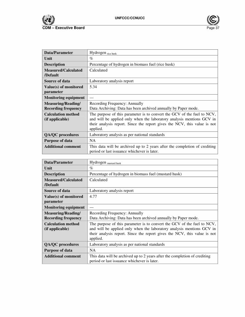
Data/Parameter Hydrogen rice husk
Unit %
Description Percentage of hydrogen in biomass fuel (rice husk)
Measured/Calculated
/Default
Calculated
Source of data Laboratory analysis report
Value(s) of monitored
parameter
5.34
Monitoring equipment ---
Measuring/Reading/
Recording frequency
Recording Frequency: Annually
Data Archiving: Data has been archived annually by Paper mode.
Calculation method
(if applicable)
The purpose of this parameter is to convert the GCV of the fuel to NCV,
and will be applied only when the laboratory analysis mentions GCV in
their analysis report. Since the report gives the NCV, this value is not
applied.
QA/QC procedures Laboratory analysis as per national standards
Purpose of data NA
Additional comment This data will be archived up to 2 years after the completion of crediting
period or last issuance whichever is later.
Data/Parameter Hydrogen mustard husk
Unit %
Description Percentage of hydrogen in biomass fuel (mustard husk)
Measured/Calculated
/Default
Calculated
Source of data Laboratory analysis report
Value(s) of monitored
parameter
4.77
Monitoring equipment ---
Measuring/Reading/
Recording frequency
Recording Frequency: Annually
Data Archiving: Data has been archived annually by Paper mode.
Calculation method
(if applicable)
The purpose of this parameter is to convert the GCV of the fuel to NCV,
and will be applied only when the laboratory analysis mentions GCV in
their analysis report. Since the report gives the NCV, this value is not
applied.
QA/QC procedures Laboratory analysis as per national standards
Purpose of data NA
Additional comment This data will be archived up to 2 years after the completion of crediting
period or last issuance whichever is later.
UNFCCC/CCNUCC
CDM – Executive Board Page 38
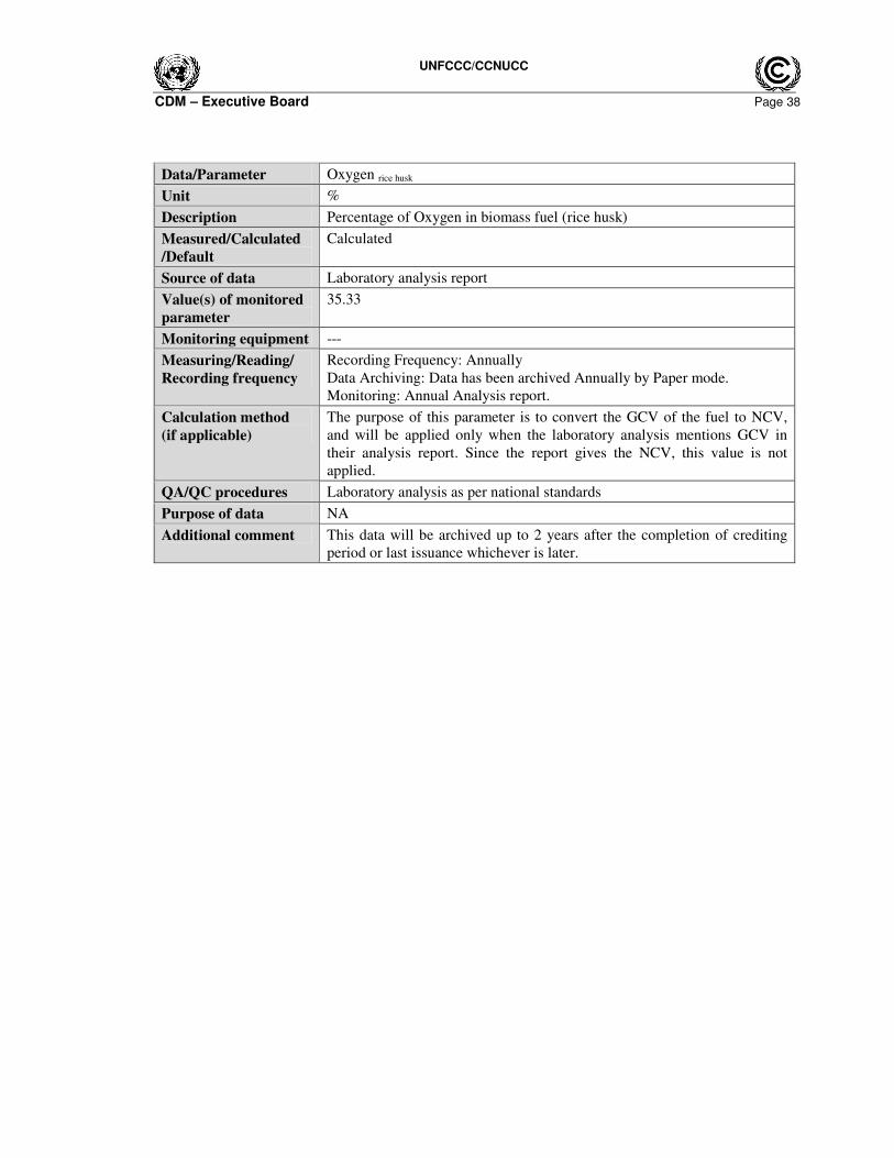
Data/Parameter Oxygen rice husk
Unit %
Description Percentage of Oxygen in biomass fuel (rice husk)
Measured/Calculated
/Default
Calculated
Source of data Laboratory analysis report
Value(s) of monitored
parameter
35.33
Monitoring equipment ---
Measuring/Reading/
Recording frequency
Recording Frequency: Annually
Data Archiving: Data has been archived Annually by Paper mode.
Monitoring: Annual Analysis report.
Calculation method
(if applicable)
The purpose of this parameter is to convert the GCV of the fuel to NCV,
and will be applied only when the laboratory analysis mentions GCV in
their analysis report. Since the report gives the NCV, this value is not
applied.
QA/QC procedures Laboratory analysis as per national standards
Purpose of data NA
Additional comment This data will be archived up to 2 years after the completion of crediting
period or last issuance whichever is later.
UNFCCC/CCNUCC
CDM – Executive Board Page 39
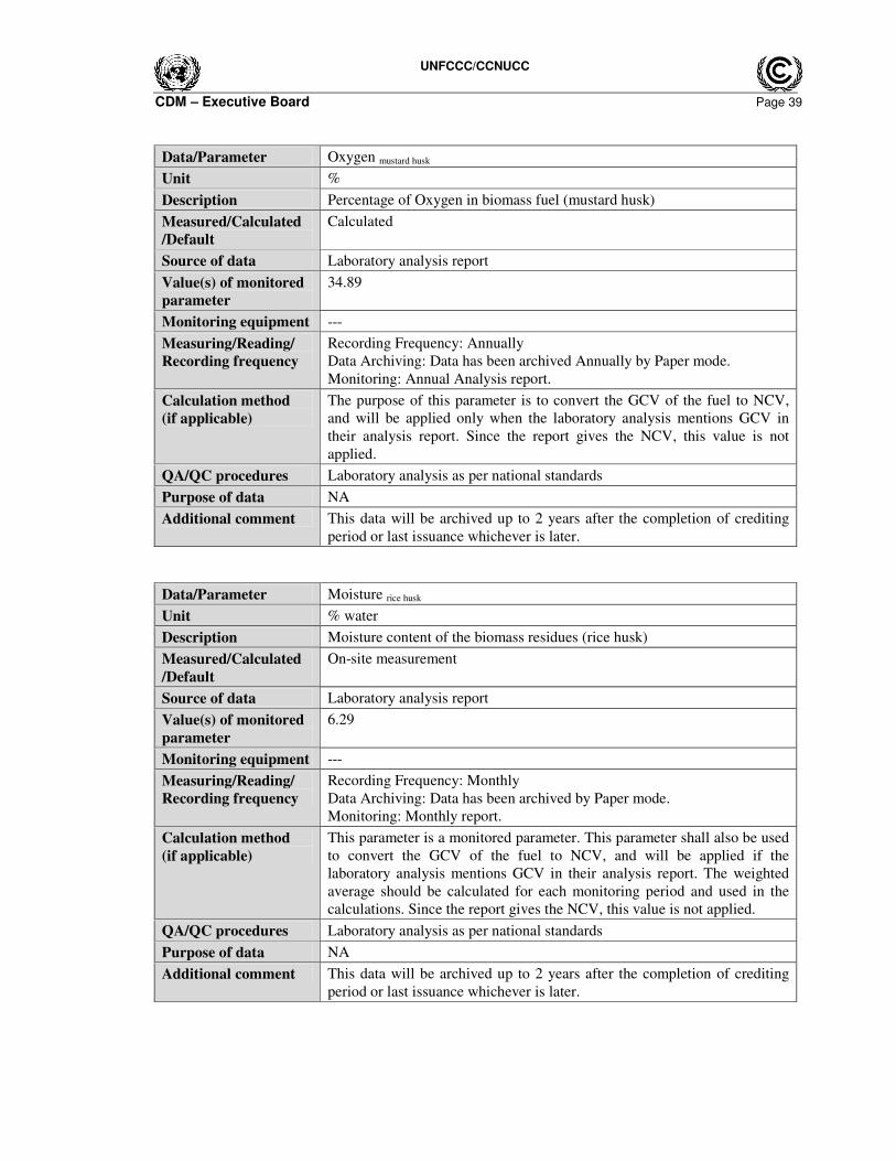
Data/Parameter Oxygen mustard husk
Unit %
Description Percentage of Oxygen in biomass fuel (mustard husk)
Measured/Calculated
/Default
Calculated
Source of data Laboratory analysis report
Value(s) of monitored
parameter
34.89
Monitoring equipment ---
Measuring/Reading/
Recording frequency
Recording Frequency: Annually
Data Archiving: Data has been archived Annually by Paper mode.
Monitoring: Annual Analysis report.
Calculation method
(if applicable)
The purpose of this parameter is to convert the GCV of the fuel to NCV,
and will be applied only when the laboratory analysis mentions GCV in
their analysis report. Since the report gives the NCV, this value is not
applied.
QA/QC procedures Laboratory analysis as per national standards
Purpose of data NA
Additional comment This data will be archived up to 2 years after the completion of crediting
period or last issuance whichever is later.
Data/Parameter Moisture rice husk
Unit % water
Description Moisture content of the biomass residues (rice husk)
Measured/Calculated
/Default
On-site measurement
Source of data Laboratory analysis report
Value(s) of monitored
parameter
6.29
Monitoring equipment ---
Measuring/Reading/
Recording frequency
Recording Frequency: Monthly
Data Archiving: Data has been archived by Paper mode.
Monitoring: Monthly report.
Calculation method
(if applicable)
This parameter is a monitored parameter. This parameter shall also be used
to convert the GCV of the fuel to NCV, and will be applied if the
laboratory analysis mentions GCV in their analysis report. The weighted
average should be calculated for each monitoring period and used in the
calculations. Since the report gives the NCV, this value is not applied.
QA/QC procedures Laboratory analysis as per national standards
Purpose of data NA
Additional comment This data will be archived up to 2 years after the completion of crediting
period or last issuance whichever is later.
UNFCCC/CCNUCC
CDM – Executive Board Page 40
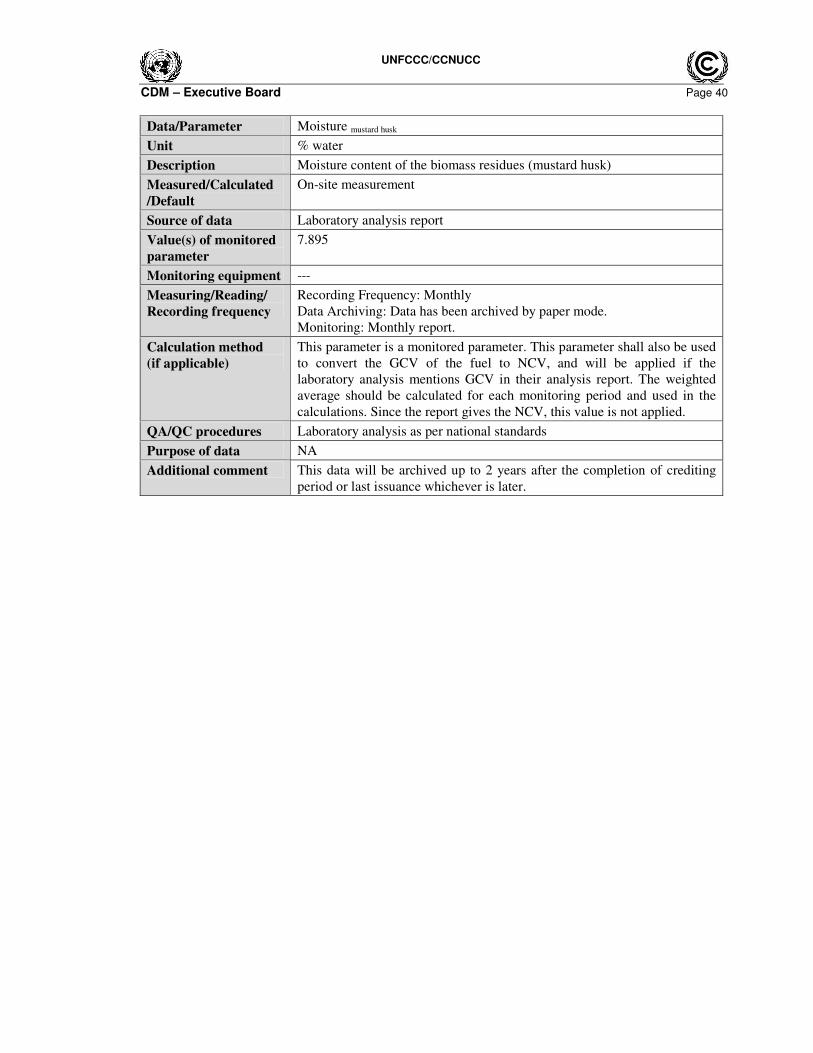
Data/Parameter Moisture mustard husk
Unit % water
Description Moisture content of the biomass residues (mustard husk)
Measured/Calculated
/Default
On-site measurement
Source of data Laboratory analysis report
Value(s) of monitored
parameter
7.895
Monitoring equipment ---
Measuring/Reading/
Recording frequency
Recording Frequency: Monthly
Data Archiving: Data has been archived by paper mode.
Monitoring: Monthly report.
Calculation method
(if applicable)
This parameter is a monitored parameter. This parameter shall also be used
to convert the GCV of the fuel to NCV, and will be applied if the
laboratory analysis mentions GCV in their analysis report. The weighted
average should be calculated for each monitoring period and used in the
calculations. Since the report gives the NCV, this value is not applied.
QA/QC procedures Laboratory analysis as per national standards
Purpose of data NA
Additional comment This data will be archived up to 2 years after the completion of crediting
period or last issuance whichever is later.
UNFCCC/CCNUCC
CDM – Executive Board Page 41
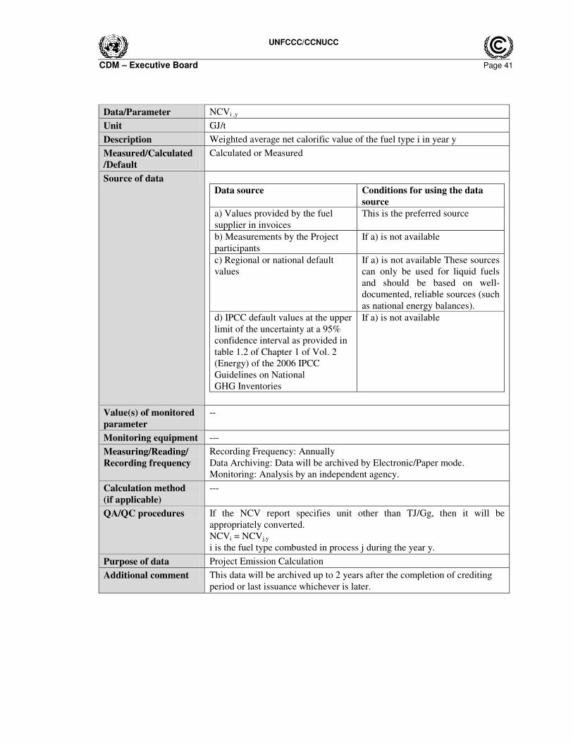
Data/Parameter NCVi ,y
Unit GJ/t
Description Weighted average net calorific value of the fuel type i in year y
Measured/Calculated
/Default
Calculated or Measured
Source of data
Data source Conditions for using the data
source
a) Values provided by the fuel
supplier in invoices
This is the preferred source
b) Measurements by the Project
participants
If a) is not available
c) Regional or national default
values
If a) is not available These sources
can only be used for liquid fuels
and should be based on well-
documented, reliable sources (such
as national energy balances).
d) IPCC default values at the upper
limit of the uncertainty at a 95%
confidence interval as provided in
table 1.2 of Chapter 1 of Vol. 2
(Energy) of the 2006 IPCC
Guidelines on National
GHG Inventories
If a) is not available
Value(s) of monitored
parameter
--
Monitoring equipment ---
Measuring/Reading/
Recording frequency
Recording Frequency: Annually
Data Archiving: Data will be archived by Electronic/Paper mode.
Monitoring: Analysis by an independent agency.
Calculation method
(if applicable)
---
QA/QC procedures If the NCV report specifies unit other than TJ/Gg, then it will be
appropriately converted.
NCVi = NCVj,y
i is the fuel type combusted in process j during the year y.
Purpose of data Project Emission Calculation
Additional comment This data will be archived up to 2 years after the completion of crediting
period or last issuance whichever is later.
UNFCCC/CCNUCC
CDM – Executive Board Page 42
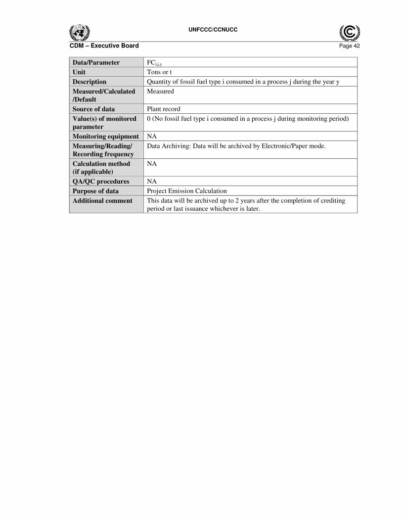
Data/Parameter FCi,j,y
Unit Tons or t
Description Quantity of fossil fuel type i consumed in a process j during the year y
Measured/Calculated
/Default
Measured
Source of data Plant record
Value(s) of monitored
parameter
0 (No fossil fuel type i consumed in a process j during monitoring period)
Monitoring equipment NA
Measuring/Reading/
Recording frequency
Data Archiving: Data will be archived by Electronic/Paper mode.
Calculation method
(if applicable)
NA
QA/QC procedures NA
Purpose of data Project Emission Calculation
Additional comment This data will be archived up to 2 years after the completion of crediting
period or last issuance whichever is later.
UNFCCC/CCNUCC
CDM – Executive Board Page 43
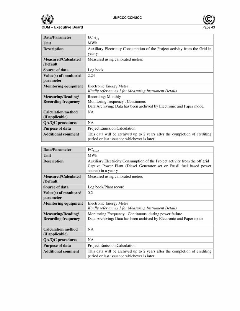
Data/Parameter EC,PJ,j,y
Unit MWh
Description Auxiliary Electricity Consumption of the Project activity from the Grid in
year y
Measured/Calculated
/Default
Measured using calibrated meters
Source of data Log book
Value(s) of monitored
parameter
2.24
Monitoring equipment Electronic Energy Meter
Kindly refer annex 1 for Measuring Instrument Details
Measuring/Reading/
Recording frequency
Recording: Monthly
Monitoring frequency : Continuous
Data Archiving: Data has been archived by Electronic and Paper mode.
Calculation method
(if applicable)
NA
QA/QC procedures NA
Purpose of data Project Emission Calculation
Additional comment This data will be archived up to 2 years after the completion of crediting
period or last issuance whichever is later.
Data/Parameter ECEL,j,y
Unit MWh
Description Auxiliary Electricity Consumption of the Project activity from the off grid
Captive Power Plant (Diesel Generator set or Fossil fuel based power
source) in a year y
Measured/Calculated
/Default
Measured using calibrated meters
Source of data Log book/Plant record
Value(s) of monitored
parameter
0.2
Monitoring equipment Electronic Energy Meter
Kindly refer annex 1 for Measuring Instrument Details
Measuring/Reading/
Recording frequency
Monitoring Frequency : Continuous, during power failure
Data Archiving: Data has been archived by Electronic and Paper mode
Calculation method
(if applicable)
NA
QA/QC procedures NA
Purpose of data Project Emission Calculation
Additional comment This data will be archived up to 2 years after the completion of crediting
period or last issuance whichever is later.
UNFCCC/CCNUCC
CDM – Executive Board Page 44
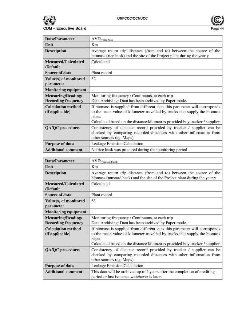
Data/Parameter AVD,y rice husk
Unit Km
Description Average return trip distance (from and to) between the source of the
biomass (rice husk) and the site of the Project plant during the year y
Measured/Calculated
/Default
Calculated
Source of data Plant record
Value(s) of monitored
parameter
32
Monitoring equipment -
Measuring/Reading/
Recording frequency
Monitoring frequency : Continuous, at each trip
Data Archiving: Data has been archived by Paper mode.
Calculation method
(if applicable)
If biomass is supplied from different sites this parameter will corresponds
to the mean value of kilometer travelled by trucks that supply the biomass
plant.
Calculated based on the distance kilometres provided buy trucker / supplier
QA/QC procedures Consistency of distance record provided by trucker / supplier can be
checked by comparing recorded distances with other information from
other sources (eg. Maps)
Purpose of data Leakage Emission Calculation
Additional comment No rice husk was procured during the monitoring period
Data/Parameter AVD,y mustard husk
Unit Km
Description Average return trip distance (from and to) between the source of the
biomass (mustard husk) and the site of the Project plant during the year y
Measured/Calculated
/Default
Calculated
Source of data Plant record
Value(s) of monitored
parameter
63
Monitoring equipment -
Measuring/Reading/
Recording frequency
Monitoring frequency : Continuous, at each trip
Data Archiving: Data has been archived by Paper mode.
Calculation method
(if applicable)
If biomass is supplied from different sites this parameter will corresponds
to the mean value of kilometer travelled by trucks that supply the biomass
plant.
Calculated based on the distance kilometres provided buy trucker / supplier
QA/QC procedures Consistency of distance record provided by trucker / supplier can be
checked by comparing recorded distances with other information from
other sources (eg. Maps)
Purpose of data Leakage Emission Calculation
Additional comment This data will be archived up to 2 years after the completion of crediting
period or last issuance whichever is later.
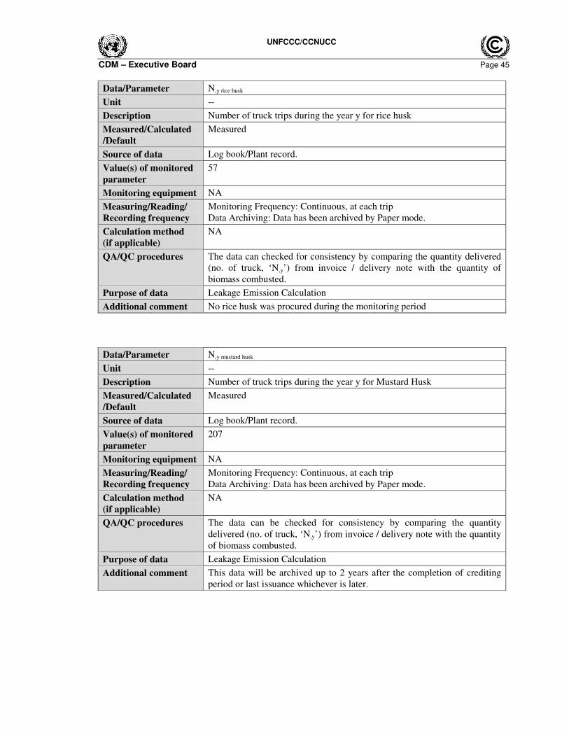
UNFCCC/CCNUCC
CDM – Executive Board Page 45
Data/Parameter N,y rice husk
Unit --
Description Number of truck trips during the year y for rice husk
Measured/Calculated
/Default
Measured
Source of data Log book/Plant record.
Value(s) of monitored
parameter
57
Monitoring equipment NA
Measuring/Reading/
Recording frequency
Monitoring Frequency: Continuous, at each trip
Data Archiving: Data has been archived by Paper mode.
Calculation method
(if applicable)
NA
QA/QC procedures The data can checked for consistency by comparing the quantity delivered
(no. of truck, ‘N,y’) from invoice / delivery note with the quantity of
biomass combusted.
Purpose of data Leakage Emission Calculation
Additional comment No rice husk was procured during the monitoring period
Data/Parameter N,y mustard husk
Unit --
Description Number of truck trips during the year y for Mustard Husk
Measured/Calculated
/Default
Measured
Source of data Log book/Plant record.
Value(s) of monitored
parameter
207
Monitoring equipment NA
Measuring/Reading/
Recording frequency
Monitoring Frequency: Continuous, at each trip
Data Archiving: Data has been archived by Paper mode.
Calculation method
(if applicable)
NA
QA/QC procedures The data can be checked for consistency by comparing the quantity
delivered (no. of truck, ‘N,y’) from invoice / delivery note with the quantity
of biomass combusted.
Purpose of data Leakage Emission Calculation
Additional comment This data will be archived up to 2 years after the completion of crediting
period or last issuance whichever is later.
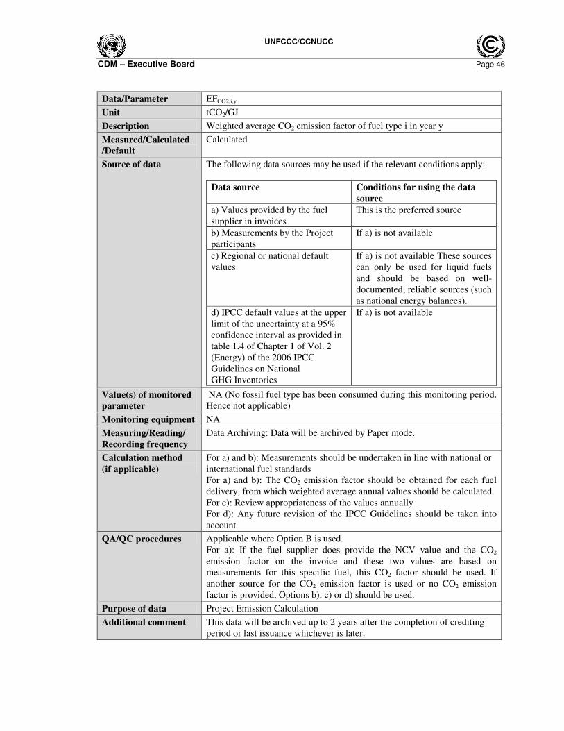
UNFCCC/CCNUCC
CDM – Executive Board Page 46
Data/Parameter EFCO2,i,y
Unit tCO2/GJ
Description Weighted average CO2 emission factor of fuel type i in year y
Measured/Calculated
/Default
Calculated
Source of data The following data sources may be used if the relevant conditions apply:
Data source Conditions for using the data
source
a) Values provided by the fuel
supplier in invoices
This is the preferred source
b) Measurements by the Project
participants
If a) is not available
c) Regional or national default
values
If a) is not available These sources
can only be used for liquid fuels
and should be based on well-
documented, reliable sources (such
as national energy balances).
d) IPCC default values at the upper
limit of the uncertainty at a 95%
confidence interval as provided in
table 1.4 of Chapter 1 of Vol. 2
(Energy) of the 2006 IPCC
Guidelines on National
GHG Inventories
If a) is not available
Value(s) of monitored
parameter
NA (No fossil fuel type has been consumed during this monitoring period.
Hence not applicable)
Monitoring equipment NA
Measuring/Reading/
Recording frequency
Data Archiving: Data will be archived by Paper mode.
Calculation method
(if applicable)
For a) and b): Measurements should be undertaken in line with national or
international fuel standards
For a) and b): The CO2 emission factor should be obtained for each fuel
delivery, from which weighted average annual values should be calculated.
For c): Review appropriateness of the values annually
For d): Any future revision of the IPCC Guidelines should be taken into
account
QA/QC procedures Applicable where Option B is used.
For a): If the fuel supplier does provide the NCV value and the CO2
emission factor on the invoice and these two values are based on
measurements for this specific fuel, this CO2 factor should be used. If
another source for the CO2 emission factor is used or no CO2 emission
factor is provided, Options b), c) or d) should be used.
Purpose of data Project Emission Calculation
Additional comment This data will be archived up to 2 years after the completion of crediting
period or last issuance whichever is later.

UNFCCC/CCNUCC
CDM – Executive Board Page 47
D.3. Implementation of sampling plan
No sampling plan needed over the monitoring period since 100% data are monitored and reported
SECTION E. Calculation of emission reductions or GHG removals by sinks
E.1. Calculation of baseline emissions or baseline net GHG removals by sinks
The baseline emissions are calculated as per paragraph 15 of the methodology:
For steam/heat produced using fossil fuels the baseline emissions are calculated as below:
22 ,,,,, *)( COFFthermalBLythermalyCOthermal EFEGBE η=
yCOthermalBE ,, 2 The baseline emissions from steam/heat displaced by the Project activity during
the year y (tCO2)
ythermalEG , The net quantity of steam/heat supplied by the Project activity during the year y
(TJ)
2, COFFEF
The CO2 emission factor of the fossil fuel that would have been used in the
baseline plant; tCO2 / TJ, obtained from reliable local or national data if
available, otherwise, IPCC default emission factors are used
thermalBL,η
The efficiency of the plant using fossil fuel that would have been used in the
absence of the Project activity
a) For Boiler:
EGthermal,boiler = Qsteam * (Hs - Hw )* 4.186 X 10⁻⁶
EGthermal Net quantity of heat supplied by the Project activity (TJ)
Qsteam Quantity of steam supplied in Tons
Hs Specific enthalpy of steam at corresponding absolute pressure and temperature at
the outlet (kCal/kg)
Hw Specific Enthalpy of feed water at corresponding temperature at the Boiler inlet
(kCal/kg)
Qsteam : 8354 Tons
Hs : 665.19 kCal/Kg
Hw : 68 kCal/Kg
ηBL,Thermal : 100 %
EFFF,CO2 : 89.5 tCO2/TJ
22 ,,,,, *)( COFFthermalBLythermalyCOthermal EFEGBE η=
EGthermal = 8354 * (665.19- 68) *4.186 X 10-6
= 20.885 TJ
Hence;
yCOthermalBE ,, 2 = (20.885 /100 %) * 89.5
= 1,869 tCO2e
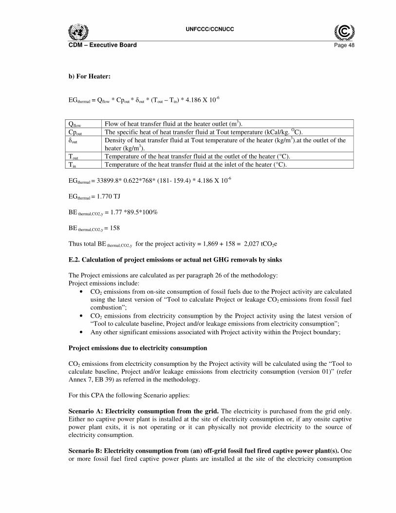
UNFCCC/CCNUCC
CDM – Executive Board Page 48
b) For Heater:
EGthermal = Qflow * Cpout * δout * (Tout – Tin) * 4.186 X 10⁻⁶
Qflow Flow of heat transfer fluid at the heater outlet (m3).
Cpout The specific heat of heat transfer fluid at Tout temperature (kCal/kg. OC).
δout Density of heat transfer fluid at Tout temperature of the heater (kg/m3).at the outlet of the
heater (kg/m3).
Tout Temperature of the heat transfer fluid at the outlet of the heater (°C).
Tin Temperature of the heat transfer fluid at the inlet of the heater (°C).
EGthermal = 33899.8* 0.622*768* (181- 159.4) * 4.186 X 10-6
EGthermal = 1.770 TJ
BE thermal,CO2,y = 1.77 *89.5*100%
BE thermal,CO2,y = 158
Thus total BE thermal,CO2,y for the project activity = 1,869 + 158 = 2,027 tCO2e
E.2. Calculation of project emissions or actual net GHG removals by sinks
The Project emissions are calculated as per paragraph 26 of the methodology:
Project emissions include:
• CO2 emissions from on-site consumption of fossil fuels due to the Project activity are calculated
using the latest version of “Tool to calculate Project or leakage CO2 emissions from fossil fuel
combustion”;
• CO2 emissions from electricity consumption by the Project activity using the latest version of
“Tool to calculate baseline, Project and/or leakage emissions from electricity consumption”;
• Any other significant emissions associated with Project activity within the Project boundary;
Project emissions due to electricity consumption
CO2 emissions from electricity consumption by the Project activity will be calculated using the “Tool to
calculate baseline, Project and/or leakage emissions from electricity consumption (version 01)” (refer
Annex 7, EB 39) as referred in the methodology.
For this CPA the following Scenario applies:
Scenario A: Electricity consumption from the grid. The electricity is purchased from the grid only.
Either no captive power plant is installed at the site of electricity consumption or, if any onsite captive
power plant exits, it is not operating or it can physically not provide electricity to the source of
electricity consumption.
Scenario B: Electricity consumption from (an) off-grid fossil fuel fired captive power plant(s). One
or more fossil fuel fired captive power plants are installed at the site of the electricity consumption
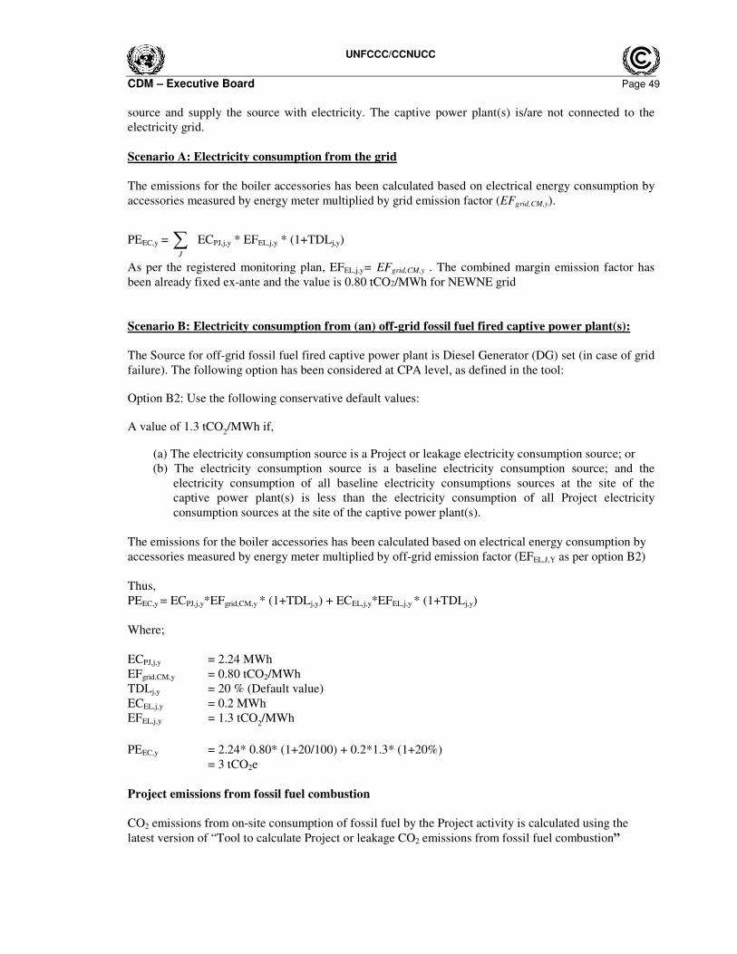
UNFCCC/CCNUCC
CDM – Executive Board Page 49
source and supply the source with electricity. The captive power plant(s) is/are not connected to the
electricity grid.
Scenario A: Electricity consumption from the grid
The emissions for the boiler accessories has been calculated based on electrical energy consumption by
accessories measured by energy meter multiplied by grid emission factor (EFgrid,CM,y).
PEEC,y = ∑J
ECPJ,j,y * EFEL,j,y * (1+TDLj,y)
As per the registered monitoring plan, EFEL,j,y= EFgrid,CM,y . The combined margin emission factor has
been already fixed ex-ante and the value is 0.80 tCO2/MWh for NEWNE grid
Scenario B: Electricity consumption from (an) off-grid fossil fuel fired captive power plant(s):
The Source for off-grid fossil fuel fired captive power plant is Diesel Generator (DG) set (in case of grid
failure). The following option has been considered at CPA level, as defined in the tool:
Option B2: Use the following conservative default values:
A value of 1.3 tCO2/MWh if,
(a) The electricity consumption source is a Project or leakage electricity consumption source; or
(b) The electricity consumption source is a baseline electricity consumption source; and the
electricity consumption of all baseline electricity consumptions sources at the site of the
captive power plant(s) is less than the electricity consumption of all Project electricity
consumption sources at the site of the captive power plant(s).
The emissions for the boiler accessories has been calculated based on electrical energy consumption by
accessories measured by energy meter multiplied by off-grid emission factor (EFEL,J,Y as per option B2)
Thus,
PEEC,y = ECPJ,j,y*EFgrid,CM,y * (1+TDLj,y) + ECEL,j,y*EFEL,j,y * (1+TDLj,y)
Where;
ECPJ,j,y = 2.24 MWh
EFgrid,CM,y = 0.80 tCO2/MWh
TDLj,y = 20 % (Default value)
ECEL,j,y = 0.2 MWh
EFEL,j,y = 1.3 tCO2/MWh
PEEC,y = 2.24* 0.80* (1+20/100) + 0.2*1.3* (1+20%)
= 3 tCO2e
Project emissions from fossil fuel combustion
CO2 emissions from on-site consumption of fossil fuel by the Project activity is calculated using the
latest version of “Tool to calculate Project or leakage CO2 emissions from fossil fuel combustion”
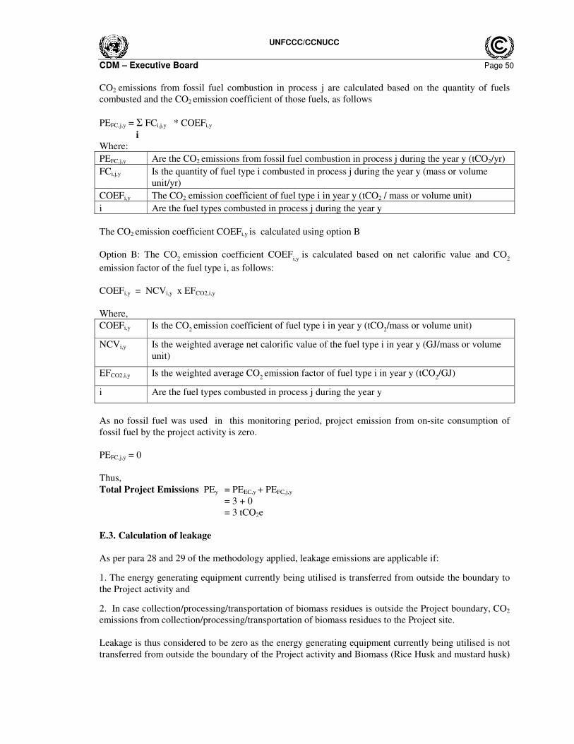
UNFCCC/CCNUCC
CDM – Executive Board Page 50
CO2 emissions from fossil fuel combustion in process j are calculated based on the quantity of fuels
combusted and the CO2 emission coefficient of those fuels, as follows
PEFC,j,y = Σ FCi,j,y * COEFi,y
i
Where:
I. PEFC,j,y II. Are the CO2 emissions from fossil fuel combustion in process j during the year y (tCO2/yr)
III. FCi,j,y IV. Is the quantity of fuel type i combusted in process j during the year y (mass or volume
unit/yr)
V. COEFi,y VI. The CO2 emission coefficient of fuel type i in year y (tCO2 / mass or volume unit)
VII. i VIII. Are the fuel types combusted in process j during the year y
The CO2 emission coefficient COEFi,y is calculated using option B
Option B: The CO2
emission coefficient COEFi,y
is calculated based on net calorific value and CO2
emission factor of the fuel type i, as follows:
COEFi,y = NCVi,y x EFCO2,i,y
Where,
COEFi,y Is the CO2 emission coefficient of fuel type i in year y (tCO
2/mass or volume unit)
NCVi,y Is the weighted average net calorific value of the fuel type i in year y (GJ/mass or volume
unit)
EFCO2,i,y Is the weighted average CO2 emission factor of fuel type i in year y (tCO
2/GJ)
i Are the fuel types combusted in process j during the year y
As no fossil fuel was used in this monitoring period, project emission from on-site consumption of
fossil fuel by the project activity is zero.
PEFC,j,y = 0
Thus,
Total Project Emissions PEy = PEEC,y + PEFC,j,y
= 3 + 0
= 3 tCO2e
E.3. Calculation of leakage
As per para 28 and 29 of the methodology applied, leakage emissions are applicable if:
1. The energy generating equipment currently being utilised is transferred from outside the boundary to
the Project activity and
2. In case collection/processing/transportation of biomass residues is outside the Project boundary, CO2
emissions from collection/processing/transportation of biomass residues to the Project site.
Leakage is thus considered to be zero as the energy generating equipment currently being utilised is not
transferred from outside the boundary of the Project activity and Biomass (Rice Husk and mustard husk)
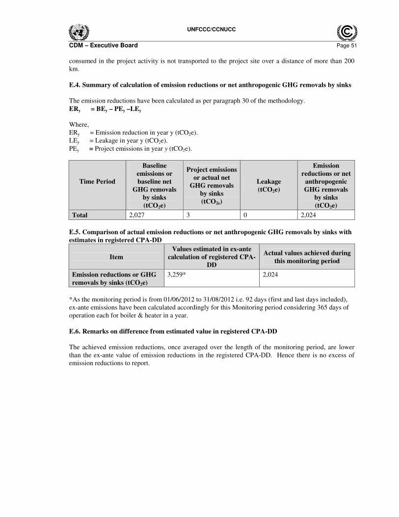
UNFCCC/CCNUCC
CDM – Executive Board Page 51
consumed in the project activity is not transported to the project site over a distance of more than 200
km.
E.4. Summary of calculation of emission reductions or net anthropogenic GHG removals by sinks
The emission reductions have been calculated as per paragraph 30 of the methodology.
ERy = BEy – PEy –LEy
Where,
ERy = Emission reduction in year y (tCO2e).
LEy = Leakage in year y (tCO2e).
PEy = Project emissions in year y (tCO2e).
Time Period
Baseline
emissions or
baseline net
GHG removals
by sinks
(tCO2e)
Project emissions
or actual net
GHG removals
by sinks
(tCO2e)
Leakage
(tCO2e)
Emission
reductions or net
anthropogenic
GHG removals
by sinks
(tCO2e)
Total 2,027 3 0 2,024
E.5. Comparison of actual emission reductions or net anthropogenic GHG removals by sinks with
estimates in registered CPA-DD
Item
Values estimated in ex-ante
calculation of registered CPA-
DD
Actual values achieved during
this monitoring period
Emission reductions or GHG
removals by sinks (tCO2e)
3,259* 2,024
*As the monitoring period is from 01/06/2012 to 31/08/2012 i.e. 92 days (first and last days included),
ex-ante emissions have been calculated accordingly for this Monitoring period considering 365 days of
operation each for boiler & heater in a year.
E.6. Remarks on difference from estimated value in registered CPA-DD
The achieved emission reductions, once averaged over the length of the monitoring period, are lower
than the ex-ante value of emission reductions in the registered CPA-DD. Hence there is no excess of
emission reductions to report.

UNFCCC/CCNUCC
CDM – Executive Board Page 52
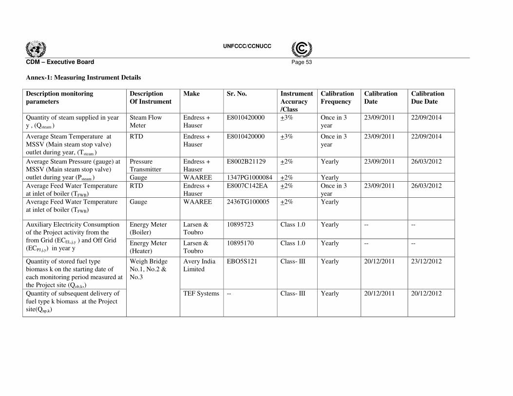
UNFCCC/CCNUCC
CDM – Executive Board Page 53
Annex-1: Measuring Instrument Details
Description monitoring
parameters
Description
Of Instrument
Make Sr. No. Instrument
Accuracy
/Class
Calibration
Frequency
Calibration
Date
Calibration
Due Date
Quantity of steam supplied in year
y , (Qsteam )
Steam Flow
Meter
Endress +
Hauser
E8010420000 +3% Once in 3
year
23/09/2011 22/09/2014
Average Steam Temperature at
MSSV (Main steam stop valve)
outlet during year, (Tsteam )
RTD Endress +
Hauser
E8010420000 +3% Once in 3
year
23/09/2011 22/09/2014
Pressure
Transmitter
Endress +
Hauser
E8002B21129 +2% Yearly 23/09/2011 26/03/2012 Average Steam Pressure (gauge) at
MSSV (Main steam stop valve)
outlet during year (Psteam ) Gauge WAAREE 1347PG1000084 +2% Yearly
Average Feed Water Temperature
at inlet of boiler (TFWB)
RTD Endress +
Hauser
E8007C142EA +2% Once in 3
year
23/09/2011 26/03/2012
Average Feed Water Temperature
at inlet of boiler (TFWB)
Gauge WAAREE 2436TG100005 +2% Yearly
Energy Meter
(Boiler)
Larsen &
Toubro
10895723 Class 1.0 Yearly -- -- Auxiliary Electricity Consumption
of the Project activity from the
from Grid (ECEL,j,y ) and Off Grid
(ECPJ,j,y) in year y Energy Meter
(Heater)
Larsen &
Toubro
10895170 Class 1.0 Yearly -- --
Quantity of stored fuel type
biomass k on the starting date of
each monitoring period measured at
the Project site (Qob,k,)
Avery India
Limited
EBO5S121
Class- III
Yearly 20/12/2011
23/12/2012
Quantity of subsequent delivery of
fuel type k biomass at the Project
site(Qnp,k)
Weigh Bridge
No.1, No.2 &
No.3
TEF Systems -- Class- III
Yearly 20/12/2011
20/12/2012
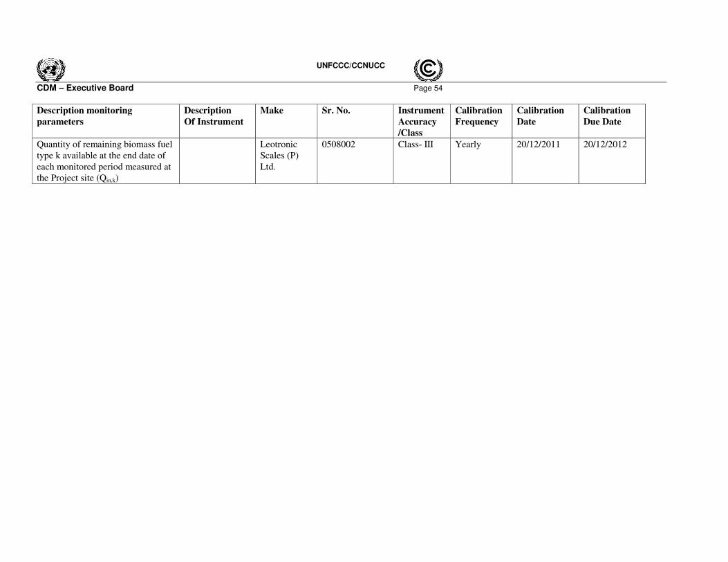
UNFCCC/CCNUCC
CDM – Executive Board Page 54
Description monitoring
parameters
Description
Of Instrument
Make Sr. No. Instrument
Accuracy
/Class
Calibration
Frequency
Calibration
Date
Calibration
Due Date
Quantity of remaining biomass fuel
type k available at the end date of
each monitored period measured at
the Project site (Qin,k)
Leotronic
Scales (P)
Ltd.
0508002 Class- III
Yearly 20/12/2011 20/12/2012

UNFCCC/CCNUCC
CDM – Executive Board Page 55
History of the document
Version Date Nature of revision
02.0 EB 66 13 March 2012
Revision required to ensure consistency with the "Guidelines for completing the monitoring report form" (EB 66, Annex 20).
01 EB 54, Annex 34 28 May 2010
Initial adoption.
Decision Class: Regulatory Document Type: Form
Business Function: Issuance