Embed Size (px)
Citation preview
Monson 1Peer Review – 24 October 2013
SPP/FIELDS LNPSPEER REVIEW
Steven Monson
University of Minnesota
Monson 2Peer Review – 24 October 2013
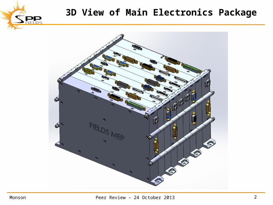
3D View of Main Electronics Package
Monson 3Peer Review – 24 October 2013
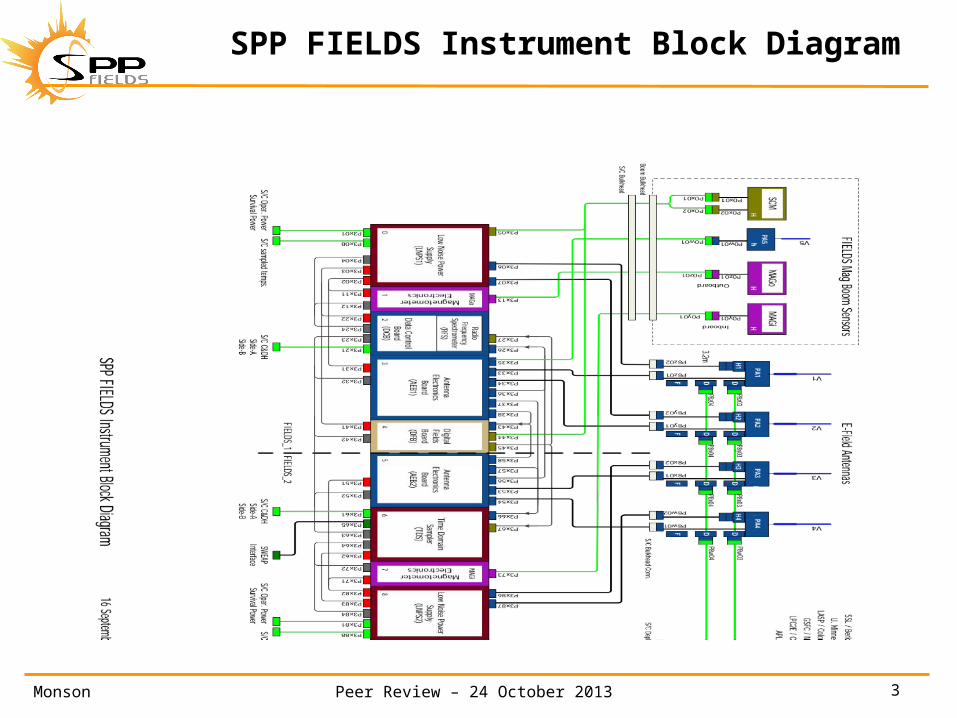
SPP FIELDS Instrument Block Diagram
Monson 4Peer Review – 24 October 2013
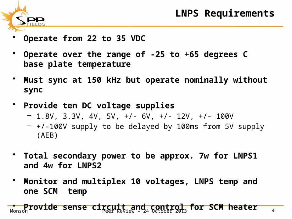
LNPS Requirements
• Operate from 22 to 35 VDC
• Operate over the range of -25 to +65 degrees C base plate temperature
• Must sync at 150 kHz but operate nominally without sync
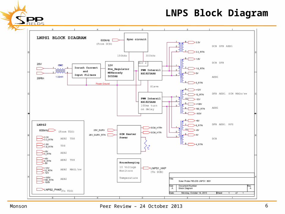
• Provide ten DC voltage supplies– 1.8V, 3.3V, 4V, 5V, +/- 6V, +/- 12V, +/- 100V– +/-100V supply to be delayed by 100ms from 5V supply (AEB)
• Total secondary power to be approx. 7w for LNPS1 and 4w for LNPS2
• Monitor and multiplex 10 voltages, LNPS temp and one SCM temp
• Provide sense circuit and control for SCM heater
• Provide pass through of some additional lines– Primary heater power for MAG and Preamps– Temperature feedback for MAG and Preamps

Monson 5Peer Review – 24 October 2013
Comparison
• STEREO/WAVES SPP/FIELDS
15 watts primary 11 watts primary LNPS1 (14w hot)
7 watts primary LNPS2 (9w hot)
100 kHz 150 kHz
LTC1149 switching regulator MSKennedy 5055RH(plastic) (LT3845A rad
hard dice)
HS1825ARH pulse width modulator same
25 degree C 55 degree C
Monson 6Peer Review – 24 October 2013
LNPS Block Diagram
Monson 7Peer Review – 24 October 2013
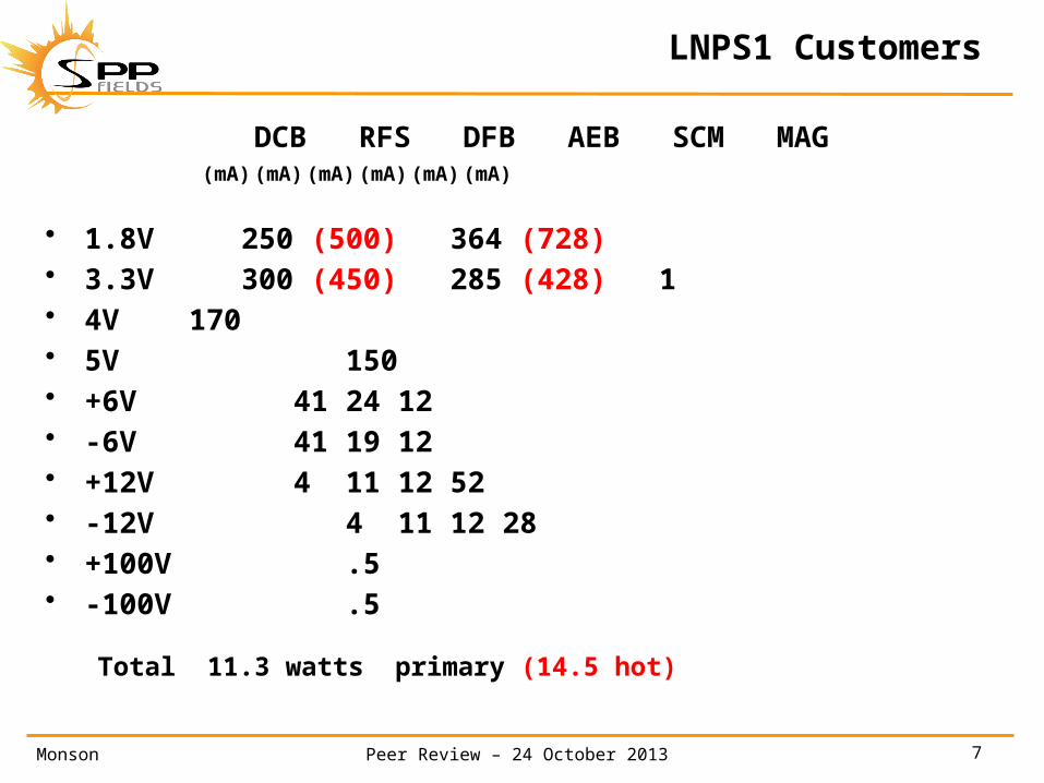
LNPS1 Customers
DCB RFS DFB AEB SCM MAG(mA) (mA) (mA) (mA) (mA) (mA)
• 1.8V 250 (500) 364 (728)• 3.3V 300 (450) 285 (428) 1• 4V 170• 5V 150• +6V 41 24 12• -6V 41 19 12• +12V 4 11 12 52• -12V 4 11 12 28• +100V .5• -100V .5
Total 11.3 watts primary (14.5 hot)
Monson 8Peer Review – 24 October 2013
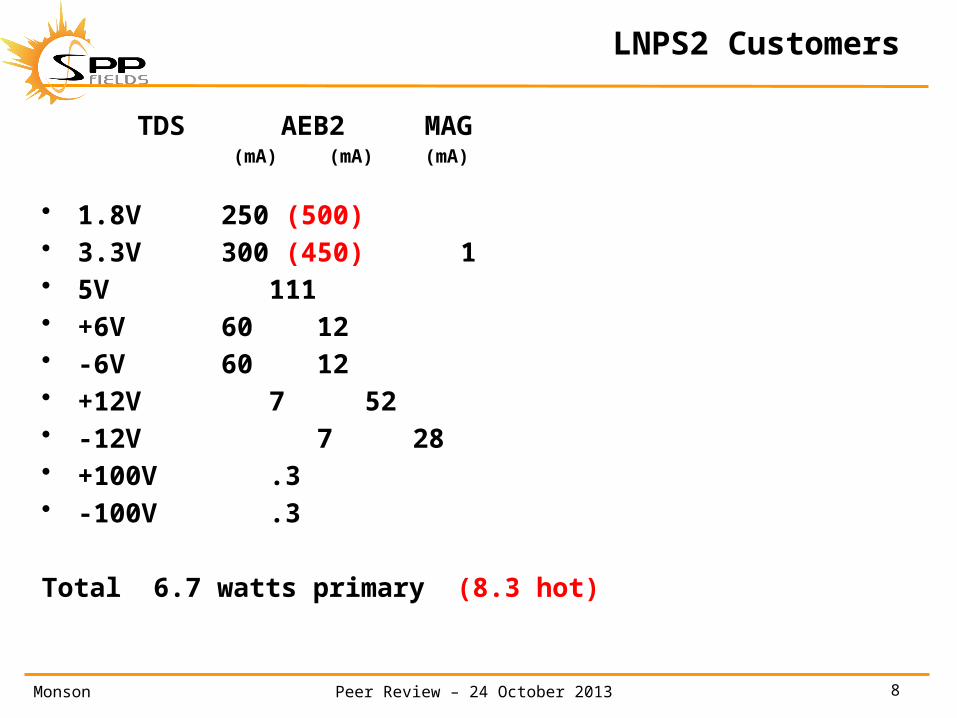
LNPS2 Customers
TDS AEB2 MAG(mA) (mA) (mA)
• 1.8V 250 (500)• 3.3V 300 (450) 1• 5V 111• +6V 60 12• -6V 60 12• +12V 7 52• -12V 7 28• +100V .3• -100V .3
Total 6.7 watts primary (8.3 hot)
Monson 9Peer Review – 24 October 2013
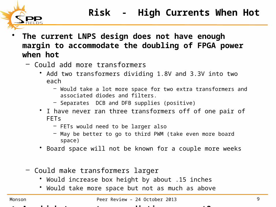
Risk - High Currents When Hot
• The current LNPS design does not have enough margin to accommodate the doubling of FPGA power when hot– Could add more transformers
• Add two transformers dividing 1.8V and 3.3V into two each– Would take a lot more space for two extra transformers and associated
diodes and filters.– Separates DCB and DFB supplies (positive)
• I have never ran three transformers off of one pair of FETs– FETs would need to be larger also– May be better to go to third PWM (take even more board space)
• Board space will not be known for a couple more weeks
– Could make transformers larger• Would increase box height by about .15 inches• Would take more space but not as much as above
• Are high temperature predictions correct?
Monson 10Peer Review – 24 October 2013
SYNC at 150 kHz
• Pre-Regulator and PWMs free run at 135kHz
• 600 kHz square wave clock– generated by DCB for LNPS1– generated by TDS for LNPS2
• Binary counter (HC4024) makes 150kHz for Pre-
Regulator and 300kHz for first PWM • Second PWM slaved from the first • All 3 operate in sync from 16V to 40V input. • In the event of sync failure, all 3 free run at 135kHz
whether sync stops up, stops down, or is removed completely.
Monson 11Peer Review – 24 October 2013
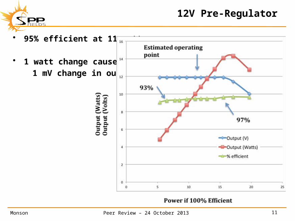
• 95% efficient at 11 watts
• 1 watt change causes only 1 mV change in output
12V Pre-Regulator
Monson 12Peer Review – 24 October 2013
1.8V / 3.3V Voltage Variations
• FPGA currents will go up when hot (LNPS1)– 614 mA could go to 1228 mA for 1.8V supply
• Transformer output will drop .1V• Two diode drops will decrease output .25V• Filter inductor looses .05V• CMC for +V and RTN drops another .24V
• Total change could be .64V– Need 1.84V minimum– Will need 2.48V out of transformer for quiet room-temperature
conditions
• Can we eliminate CMCs on the 1.8V and 3.3V supplies?
Monson 13Peer Review – 24 October 2013
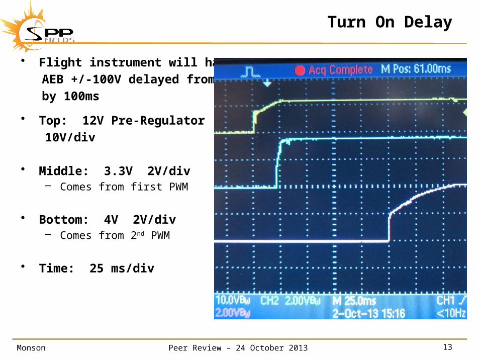
Turn On Delay
• Flight instrument will haveAEB +/-100V delayed from +5Vby 100ms
• Top: 12V Pre-Regulator 10V/div
• Middle: 3.3V 2V/div– Comes from first PWM
• Bottom: 4V 2V/div– Comes from 2nd PWM
• Time: 25 ms/div
Monson 14Peer Review – 24 October 2013
Voltage Ripple
• Not able to measure until we have a working EM in box
• Will depend on how much loads vary
• Measurements from STEREO/WAVES of complete operating instrument with true RMS meter (300kHz bandwidth):– 12V Pre-Regulator 25 mV– +/- 8V 20mV– +5V 30 mV– +5V DPU 100 mV
Monson 15Peer Review – 24 October 2013
Low Voltage Turn 0n
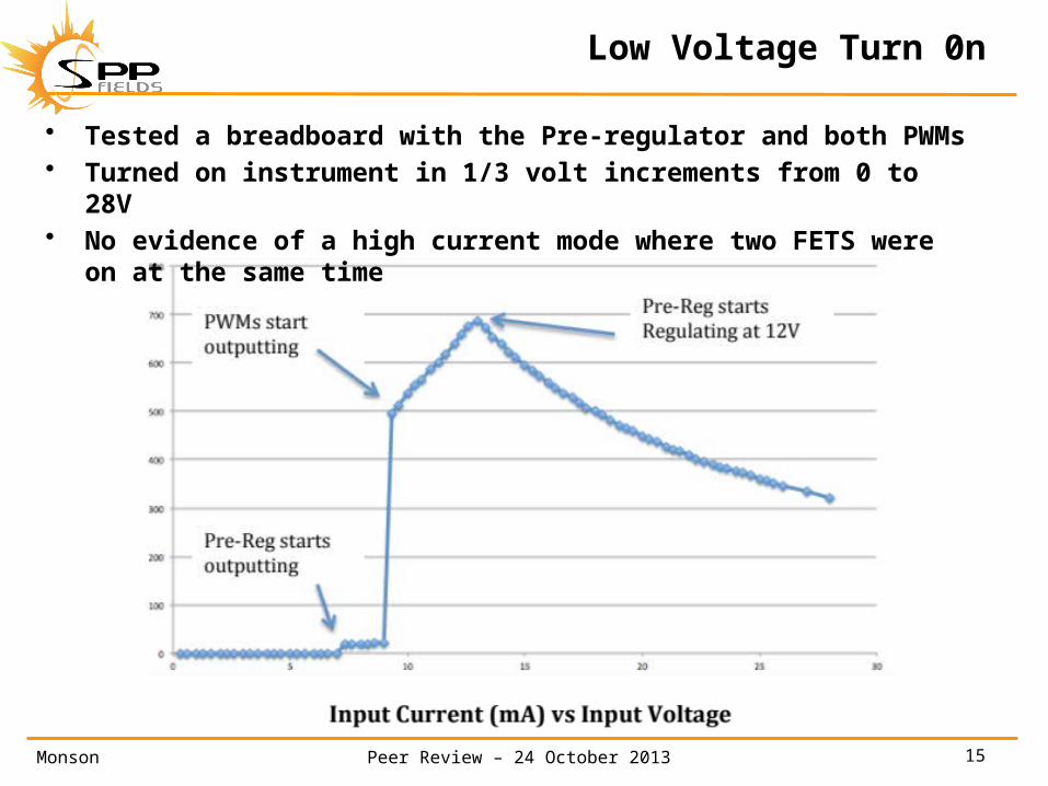
• Tested a breadboard with the Pre-regulator and both PWMs
• Turned on instrument in 1/3 volt increments from 0 to 28V • No evidence of a high current mode where two FETS were
on at the same time
Monson 16Peer Review – 24 October 2013
Inrush current
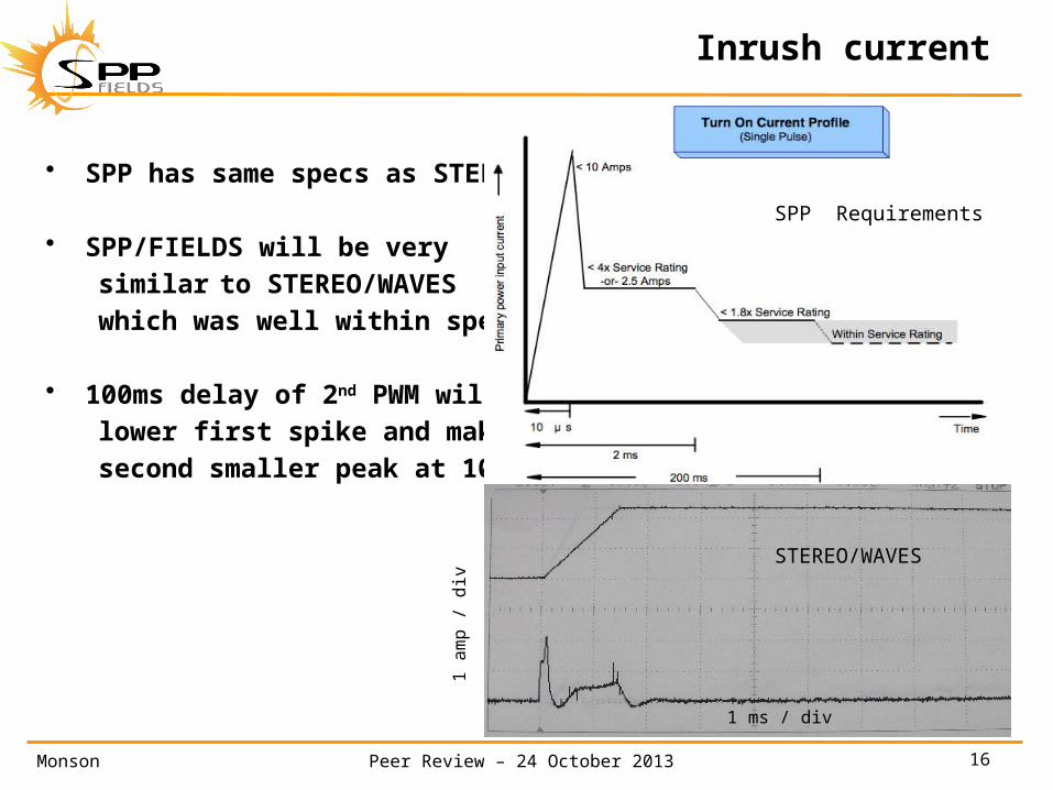
• SPP has same specs as STEREO
• SPP/FIELDS will be very similar to STEREO/WAVES which was well within spec
• 100ms delay of 2nd PWM will lower first spike and make a second smaller peak at 100ms
1 ms / div
1 a
mp /
div
STEREO/WAVES
SPP Requirements