Embed Size (px)
Citation preview
1. TECHNICAL SPECIFICATIONS – MECHANICAL ASPECTS
1.1. GeneralUnless otherwise specifically described, the mechanical installations to be installed comprise all plant required for the proper functioning of the WWTP. These installations are described in this chapter as well as on the P&ID’s and the drawings shown in Appendix I. Further general technical specifications are elaborated in volume 3C of these Employer’s Requirements and apply to these installations.
Sufficient piping and valves shall be provided to ensure easy maintenance of the facilities without interrupting the wastewater treatment capacity (maximum design capacity).
In some cases “package units” are specified. A package unit is an autonomously working unit with data communication with the process automation system.
1.2. Demolition WorksAll mechanical components which are no longer used in the rehabilitated plant (see Civil Aspects – structures to be demolished), shall be demolished by the Contractor. Section 5.1 of Volume 3A is applicable.
1.3. InletThe influent from Sibiu and the influent from Selimbar, Cisnadie and Mohu are collected in the inlet chamber of the Wastewater Treatment Plant (WWTP). After the inlet chamber at the WWTP inlet structure a static coarse screen shall be installed. Before the inlet chambers an overflow weir is located to discharge influent to the Cibin River in case of calamity. A slide damper will dampen turbulence in the main influent flow
Mechanical installations for the inlet comprise, but are not limited to, the following equipment:- Static coarse screen (at the WWTP inlet structure).- Adjustable overflow weir (at the main weir gate).- Slide damper (at the main weir gate).
general system requirements
Static coarse screenAmount [-] : 1Mesh size [mm] : 100Material : AISI 304 L
Adjustable overflow to Cibin River :Amount [-] : 1Length [mm] : See drawing Rom32.1.3.103Material : AISI 304 L
Slide damperAmount [-] : 1Length [mm] : See drawing Rom32.1.3.103Material : AISI 304 L
1.4. Automatic coarse and fine screens with screenings washing and handlingThe inlet of the waterline is provided with coarse screening to 25mm and fine screening to 6mm. Two automatic coarse screens and two automatic fine screens shall be installed. Two screenings conditioning units shall be provided operating as duty/duty with each unit sized to
take 100 % of the total flow. Each screening “street” shall be able to be operated individually, when the other “street” is out of operation.
The screens shall be automatically cleaned by washing and brushing or by raking. The cleaning cycle shall operate on the differential water level across the screens. Non-potable water shall be used for flushing of the screening material. Reject water shall gravitate to the channels of the screens. Screenings of the fine and the coarse screens are washed, pressed and collected in two separate containers for removal. Isolation of the screens is effected via manually actuated penstocks. Two isolation penstocks shall be provided to allow full isolation of each set of coarse and fine screens. Penstock frames shall be of stainless steel with doors of a suitable composite plastic material.
Containers shall be covered by an air extraction hood during filling to minimise obnoxious smells and connected to a stainless steel ventilation duct connected to the ventilation system. The requirements for the screening containers are that they must be draining through a screen at the bottom and that the water shall be discharged through a 60 mm stopcock above a large floor drain.
The mechanical installation of the screens comprises, but is not limited to, the following equipment:- 2 coarse screens;- 2 fine screens;- 2 screw conveyers;- 4 connecting pieces between screens and conveyers;- 2 compactors with press-pipes;- 2 screenings washing systems using non-potable-water supplied from the non-potable-
water system (could be combined with compactor);- 3 containers (2 duty, 1 exchange).
general system requirements
Automatic coarse screensAmount [-] : 2Mesh size [mm] : 25Maximum velocity between bars [m/s] : 1.0Minimum velocity between bars [m/s] : 0.25Minimum flow coarse screen [m3/h/piece] : Approx. 2.300, See PFDMaximum flow coarse screen [m3/h/piece] : Approx. 4.500, See PFDMaterial screens : AISI 304 L
Automatic fine screensAmount [-] : 2Mesh size [mm] : 6Maximum velocity between bars [m/s] : 1.0Minimum velocity between bars [m/s] : 0.25Minimum flow fine screen [m3/h/piece] : Approx. 2.300, See PFDMaximum flow fine screen [m3/h/piece] : 4.500, See PFDMaterial screens : AISI 304 L
Transport screwsAmount [-] : 2Diameter [mm] : 300 Capacity [m3/h] : 5
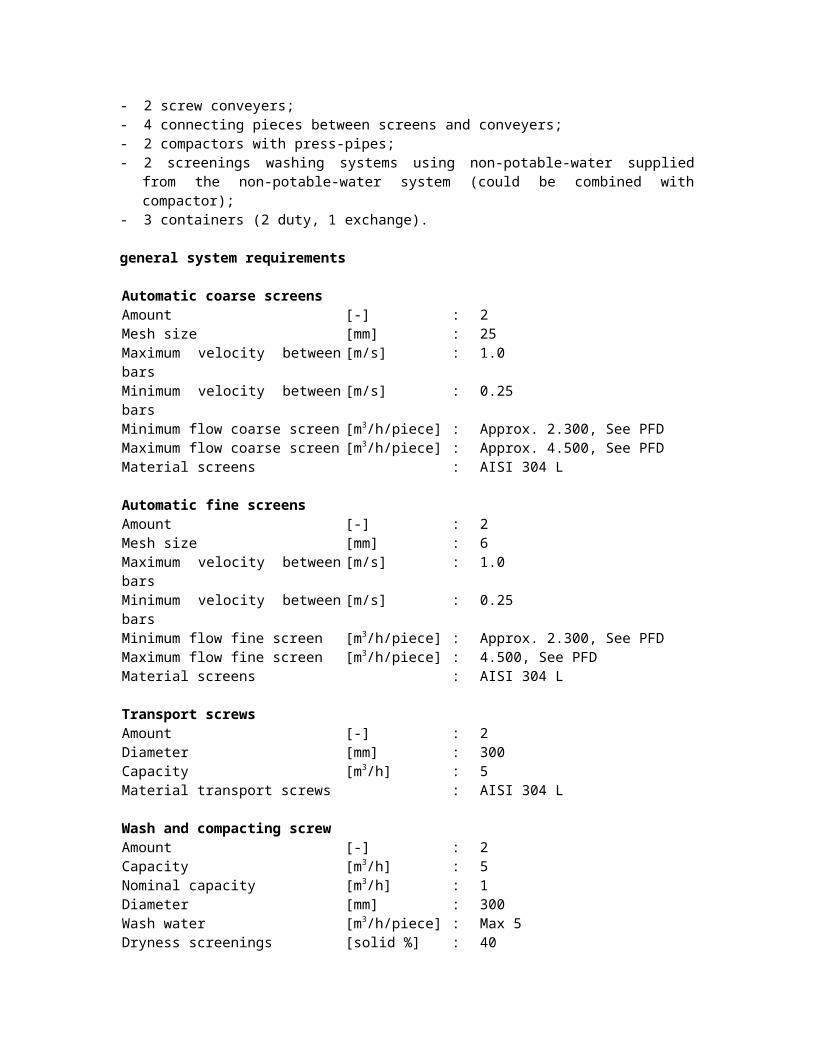
Material transport screws : AISI 304 L
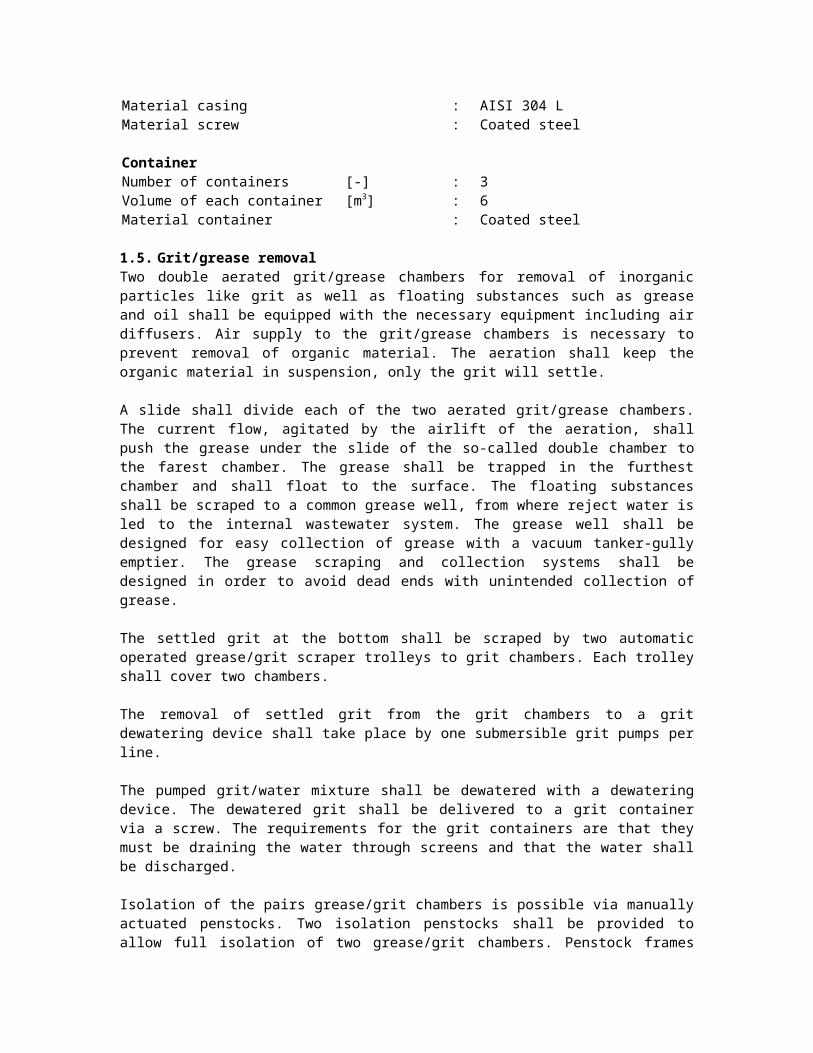
Wash and compacting screwAmount [-] : 2Capacity [m3/h] : 5Nominal capacity [m3/h] : 1Diameter [mm] : 300 Wash water [m3/h/piece] : Max 5Dryness screenings [solid %] : 40Material casing : AISI 304 LMaterial screw : Coated steel
ContainerNumber of containers [-] : 3Volume of each container [m3] : 6 Material container : Coated steel
1.5. Grit/grease removalTwo double aerated grit/grease chambers for removal of inorganic particles like grit as well as floating substances such as grease and oil shall be equipped with the necessary equipment including air diffusers. Air supply to the grit/grease chambers is necessary to prevent removal of organic material. The aeration shall keep the organic material in suspension, only the grit will settle.
A slide shall divide each of the two aerated grit/grease chambers. The current flow, agitated by the airlift of the aeration, shall push the grease under the slide of the so-called double chamber to the farest chamber. The grease shall be trapped in the furthest chamber and shall float to the surface. The floating substances shall be scraped to a common grease well, from where reject water is led to the internal wastewater system. The grease well shall be designed for easy collection of grease with a vacuum tanker-gully emptier. The grease scraping and collection systems shall be designed in order to avoid dead ends with unintended collection of grease.
The settled grit at the bottom shall be scraped by two automatic operated grease/grit scraper trolleys to grit chambers. Each trolley shall cover two chambers.
The removal of settled grit from the grit chambers to a grit dewatering device shall take place by one submersible grit pumps per line.
The pumped grit/water mixture shall be dewatered with a dewatering device. The dewatered grit shall be delivered to a grit container via a screw. The requirements for the grit containers are that they must be draining the water through screens and that the water shall be discharged.
Isolation of the pairs grease/grit chambers is possible via manually actuated penstocks. Two isolation penstocks shall be provided to allow full isolation of two grease/grit chambers. Penstock frames shall be of stainless steel with doors of a suitable composite plastic material.
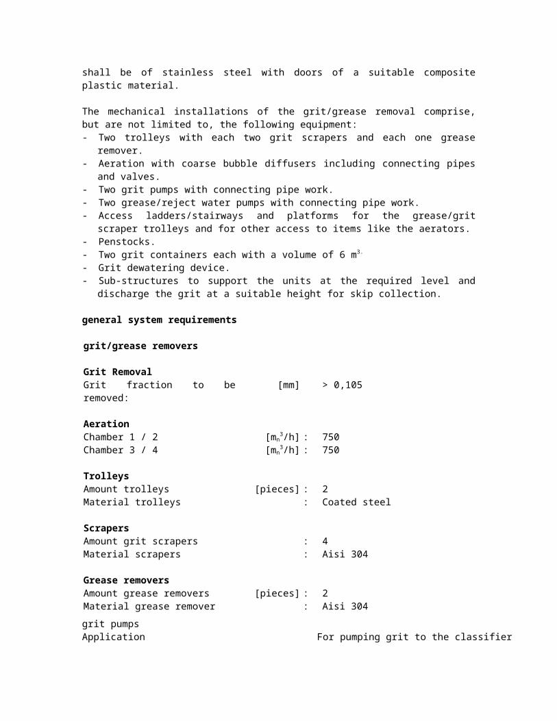
The mechanical installations of the grit/grease removal comprise, but are not limited to, the following equipment:- Two trolleys with each two grit scrapers and each one grease remover.- Aeration with coarse bubble diffusers including connecting pipes and valves.
- Two grit pumps with connecting pipe work.- Two grease/reject water pumps with connecting pipe work.- Access ladders/stairways and platforms for the grease/grit scraper trolleys and for other
access to items like the aerators.- Penstocks.- Two grit containers each with a volume of 6 m3.
- Grit dewatering device.- Sub-structures to support the units at the required level and discharge the grit at a
suitable height for skip collection.
general system requirements
grit/grease removers
Grit RemovalGrit fraction to be removed: [mm] > 0,105
AerationChamber 1 / 2 [mn
3/h] : 750Chamber 3 / 4 [mn
3/h] : 750
TrolleysAmount trolleys [pieces] : 2Material trolleys : Coated steel
ScrapersAmount grit scrapers : 4Material scrapers : Aisi 304
Grease removersAmount grease removers [pieces] : 2Material grease remover : Aisi 304
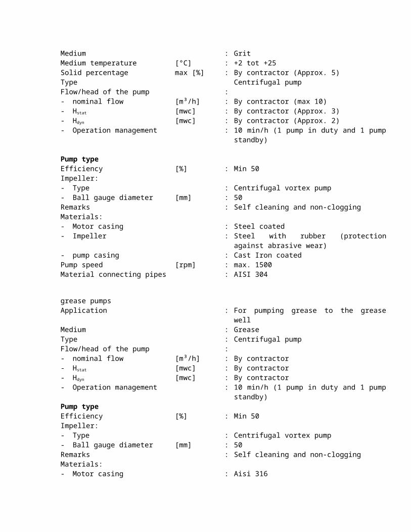
grit pumpsApplication For pumping grit to the classifierMedium : GritMedium temperature [°C] : +2 tot +25Solid percentage max [%] : By contractor (Approx. 5)Type Centrifugal pumpFlow/head of the pump :- nominal flow [m³/h] : By contractor (max 10)- Hstat [mwc] : By contractor (Approx. 3)- Hdyn [mwc] : By contractor (Approx. 2) - Operation management : 10 min/h (1 pump in duty and 1 pump standby)
Pump typeEfficiency [%] : Min 50Impeller:- Type : Centrifugal vortex pump- Ball gauge diameter [mm] : 50Remarks : Self cleaning and non-cloggingMaterials:- Motor casing : Steel coated
- Impeller : Steel with rubber (protection against abrasive wear)
- pump casing : Cast Iron coatedPump speed [rpm] : max. 1500Material connecting pipes : AISI 304
grease pumpsApplication : For pumping grease to the grease wellMedium : GreaseType : Centrifugal pumpFlow/head of the pump :- nominal flow [m³/h] : By contractor - Hstat [mwc] : By contractor - Hdyn [mwc] : By contractor - Operation management : 10 min/h (1 pump in duty and 1 pump standby)Pump typeEfficiency [%] : Min 50Impeller:- Type : Centrifugal vortex pump- Ball gauge diameter [mm] : 50Remarks : Self cleaning and non-cloggingMaterials:- Motor casing : Aisi 316- Impeller : Cr-steel- pump casing : Aisi 316Pump speed [rpm] : max. 1500Material connecting pipes : AISI 304L
Grit DewateringAmount [-] : 1Capacity [m3/h] : Max flow of a grit pumpDiameter [mm] : 300 Dewatering capacity [m3/h] : Max 5Material casing : AISI 304 LMaterial screw : Coated steelOther technical arrangements : High level grit dewatering
Grit ContainerAmount [-] : 2Volume [m3] : 6 Drainage water outlet [mm] : Min 60 Material container : Coated steel
1.5.1. Blower Station for Grit/Grease ChambersTwo blowers of the lobe type shall be installed for the air supply to the Grit/Grease Chambers and to the possible air lift pumps for the grit removal. A minimum of 100 % reserve capacity of the total aeration capacity shall be installed.
Blower Station for Grit/Grease comprises, but is not limited to, the following equipment:- Complete blower installation existing of two blowers with connections to the piping
system.
- Noise hoods.- The foundation of the blowers, and connections to piping system shall be installed with
necessary compensatory and vibration-absorbing arrangements.
general system requirementsApplication : Aeration for the grit/grease removersNumber compressors in operation:- Minimum : 1- Maximum : 2Capacity / compressor: [mn
3/h] : 750Maximum discharge pressure [bar absolute] : By contractor (approx. 1,3)Medium : atmospheric air
1.6. Distribution Chamber No. 1The return sludge and the incoming influent are mixed in the distribution chamber No1 (static mixer). The flow is divided to the three activated sludge tanks. The weir plates in the distribution chamber for the Aeration Tanks shall be adjustable in height to obtain equal distribution of the wastewater to the tanks.
The installation comprises, but is not limited to, the following equipment:- 3 adjustable weir plates;
The adjustable weirs are manually actuated. A closed weir shall be provided to allow full isolation of an activated sludge tank. The overflow weirs shall be made of stainless steel with a minimum wall thickness of 2.5 mm. The lengths of the weir plates are indicated on the enclosed drawings. Stationary bridges are assumed to be necessary for operation of the weirs.
1.7. Activated Sludge TanksEach Activated Sludge Tank is divided in different zones:- 1 x Denitrification zone.- 3 x Nitrification zone.
The nitrification zones of the three Activated Sludge Tanks shall be aerated with fine bubble aeration by disc or plate diffusers. Mixers in denitrification zones shall keep the sludge suspended and prevent precipitation of the sludge.
The aeration sections and mixers shall be placed thus that the best possible aeration and mixing is achieved and sediments and scum are minimised. The rotational speed of the mixers shall not disturb the biological process.
Disc diffusers/Plate diffusers shall be installed in the nitrification zones. The membranes shall be made of EPDM/poly-urethane based rubbers. No ceramic disc diffuser shall be used. The disc diffusers/plate diffusers shall be mounted on plastic or stainless steel pipe work. The minimum lifetime guarantee of the manufacturer of the diffusers shall be 10 years.
The design of the aeration system shall be based on the required oxygen quantity.
Installations for the Activated Sludge Tanks comprise, but are not limited to, the following equipment:- air supply pipes; - aeration headers; - 12 mixers;
- 3 recirculation pumps;- outlet weirs; - platforms; - stairs;- lifting equipment;
general system requirements Activated Sludge TankActivated sludge tankAmount [-] : 3Water depth [m] : 4,5Volume per tank [m3] : 5.730Total activated sludge volume [m3] : 17.200Sludge content [kg/m3] : 4,5BOD sludge loading rate [kg BOD/(kg MLSS d)] : 0.11Recirculation flow [m3/h] : 6.000, See PFD
Oxygen demandOxygen demand alpha OC [kg O2/h] : 1.266Alpha factor [-] : 0,65Required oxygen quantity [kg O2/h] : 1.947Specific oxygen transfer [g O2/mn
3 m-1] : 17 Required volume of air [mn
3/h] : 25.500
1.7.1. MixersMixers shall keep the sludge in the denitrification zones in suspension. The amount of mixers is indicative.
general system requirements mixersPropeller- Amount blades : 3Jetring : NoMaterials- Propeller : Stainless steel AISI 316- bolts and nuts : Stainless steel AISI 316- motor casing : Stainless steel AISI 316Propellor speed [rpm] : max. 315Sealing : Maintainable double mechanical sealsOil chamber : Water in oil detection with relaisAdditional : Leading beamMaterial leading beam : Stainless steel AISI 316
1.7.2. Recirculation PumpsOne recirculation pump in each activated sludge tank shall recirculate the activated sludge mixture from the end of the oxic zones to the beginning of the anoxic zone. Each recirculation pump shall be installed with a non-return valve and a short pressure pipe. The pumps shall be axial, submersible pumps.
general system requirements Recirculation PumpsApplication : Recirculation activated sludge mixture in
activated sludge tanksMedium : Activated sludgeMedium temperature [°C] : +2 tot +25Type : Horizontal submersible axial impeller pumps
Flow/head of the pump :- Nominal flow [m³/h] : 2.000, See PFD- Hstat [mwc] : By contractor (Approx. 0,1)- Hdyn [mwc] : By contractor (Approx. 1) - Operation management : Continuous
Pump typeEfficiency [%] : Min. 40 %Impeller:- Type : Axial impeller- Diameter [mm] :Remarks : Self cleaning and non cloggingMaterials:- Motor casing : Stainless steel AISI 316- Impeller : Stainless steel AISI 316- Pump casing : Cast Iron coatedPump speed [rpm] : Max. 1000Sealing : Double mechanical sealOil chamber : Water in oil detection with relay
1.7.3. Additional PumpA portable submersible pump with enough capacity including flexible hoses (6 bar) for emptying one tank in 48 hours shall be included in the supply.
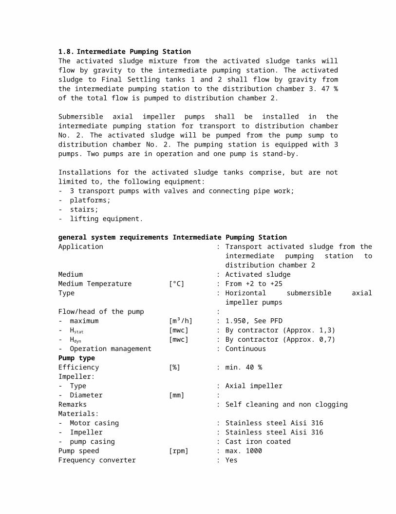
1.8. Intermediate Pumping StationThe activated sludge mixture from the activated sludge tanks will flow by gravity to the intermediate pumping station. The activated sludge to Final Settling tanks 1 and 2 shall flow by gravity from the intermediate pumping station to the distribution chamber 3. 47 % of the total flow is pumped to distribution chamber 2.
Submersible axial impeller pumps shall be installed in the intermediate pumping station for transport to distribution chamber No. 2. The activated sludge will be pumped from the pump sump to distribution chamber No. 2. The pumping station is equipped with 3 pumps. Two pumps are in operation and one pump is stand-by.
Installations for the activated sludge tanks comprise, but are not limited to, the following equipment:- 3 transport pumps with valves and connecting pipe work;- platforms; - stairs;- lifting equipment.
general system requirements Intermediate Pumping StationApplication : Transport activated sludge from the intermediate
pumping station to distribution chamber 2Medium : Activated sludgeMedium Temperature [°C] : From +2 to +25Type : Horizontal submersible axial impeller pumpsFlow/head of the pump :- maximum [m³/h] : 1.950, See PFD- Hstat [mwc] : By contractor (Approx. 1,3)- Hdyn [mwc] : By contractor (Approx. 0,7) - Operation management : Continuous
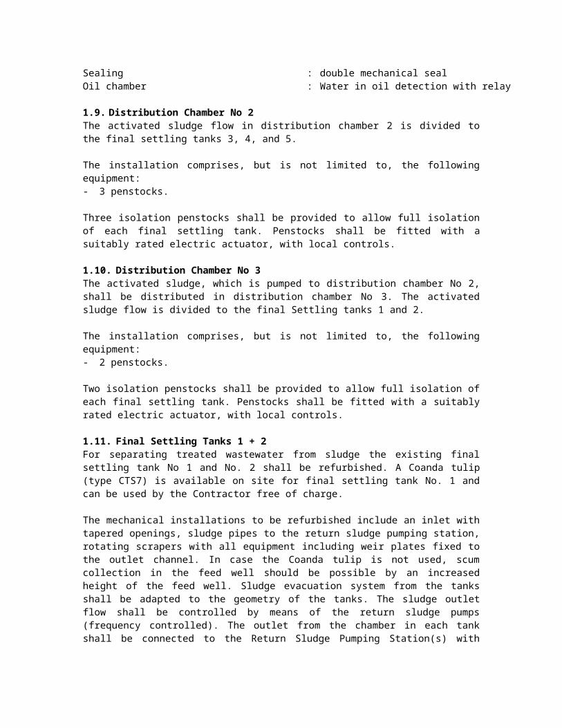
Pump typeEfficiency [%] : min. 40 %Impeller:- Type : Axial impeller- Diameter [mm] :Remarks : Self cleaning and non cloggingMaterials:- Motor casing : Stainless steel Aisi 316- Impeller : Stainless steel Aisi 316- pump casing : Cast iron coatedPump speed [rpm] : max. 1000Frequency converter : YesSealing : double mechanical sealOil chamber : Water in oil detection with relay
1.9. Distribution Chamber No 2The activated sludge flow in distribution chamber 2 is divided to the final settling tanks 3, 4, and 5.
The installation comprises, but is not limited to, the following equipment:- 3 penstocks.
Three isolation penstocks shall be provided to allow full isolation of each final settling tank. Penstocks shall be fitted with a suitably rated electric actuator, with local controls.
1.10. Distribution Chamber No 3The activated sludge, which is pumped to distribution chamber No 2, shall be distributed in distribution chamber No 3. The activated sludge flow is divided to the final Settling tanks 1 and 2.
The installation comprises, but is not limited to, the following equipment:- 2 penstocks.
Two isolation penstocks shall be provided to allow full isolation of each final settling tank. Penstocks shall be fitted with a suitably rated electric actuator, with local controls.
1.11. Final Settling Tanks 1 + 2For separating treated wastewater from sludge the existing final settling tank No 1 and No. 2 shall be refurbished. A Coanda tulip (type CTS7) is available on site for final settling tank No. 1 and can be used by the Contractor free of charge.
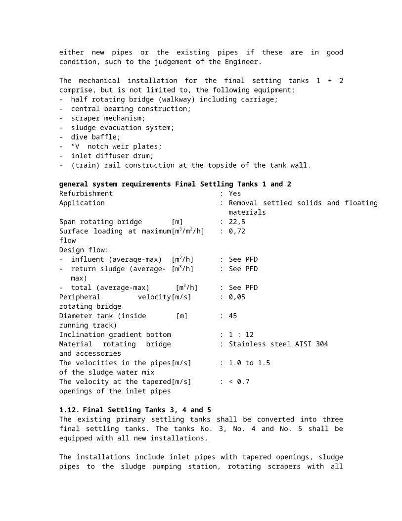
The mechanical installations to be refurbished include an inlet with tapered openings, sludge pipes to the return sludge pumping station, rotating scrapers with all equipment including weir plates fixed to the outlet channel. In case the Coanda tulip is not used, scum collection in the feed well should be possible by an increased height of the feed well. Sludge evacuation system from the tanks shall be adapted to the geometry of the tanks. The sludge outlet flow shall be controlled by means of the return sludge pumps (frequency controlled). The outlet from the chamber in each tank shall be connected to the Return Sludge Pumping Station(s) with either new pipes or the existing pipes if these are in good condition, such to the judgement of the Engineer.
The mechanical installation for the final setting tanks 1 + 2 comprise, but is not limited to, the following equipment:
- half rotating bridge (walkway) including carriage;- central bearing construction;- scraper mechanism;- sludge evacuation system;- dive baffle;- “V” notch weir plates;- inlet diffuser drum;- (train) rail construction at the topside of the tank wall.
general system requirements Final Settling Tanks 1 and 2Refurbishment : YesApplication : Removal settled solids and floating materialsSpan rotating bridge [m] : 22,5Surface loading at maximum flow [m3/m2/h] : 0,72Design flow:- influent (average-max) [m3/h] : See PFD- return sludge (average-max) [m3/h] : See PFD- total (average-max) [m3/h] : See PFDPeripheral velocity rotating bridge [m/s] : 0,05Diameter tank (inside running track) [m] : 45Inclination gradient bottom : 1 : 12Material rotating bridge and accessories
: Stainless steel AISI 304
The velocities in the pipes of the sludge water mix
[m/s] : 1.0 to 1.5
The velocity at the tapered openings of the inlet pipes
[m/s] : < 0.7
1.12. Final Settling Tanks 3, 4 and 5The existing primary settling tanks shall be converted into three final settling tanks. The tanks No. 3, No. 4 and No. 5 shall be equipped with all new installations.
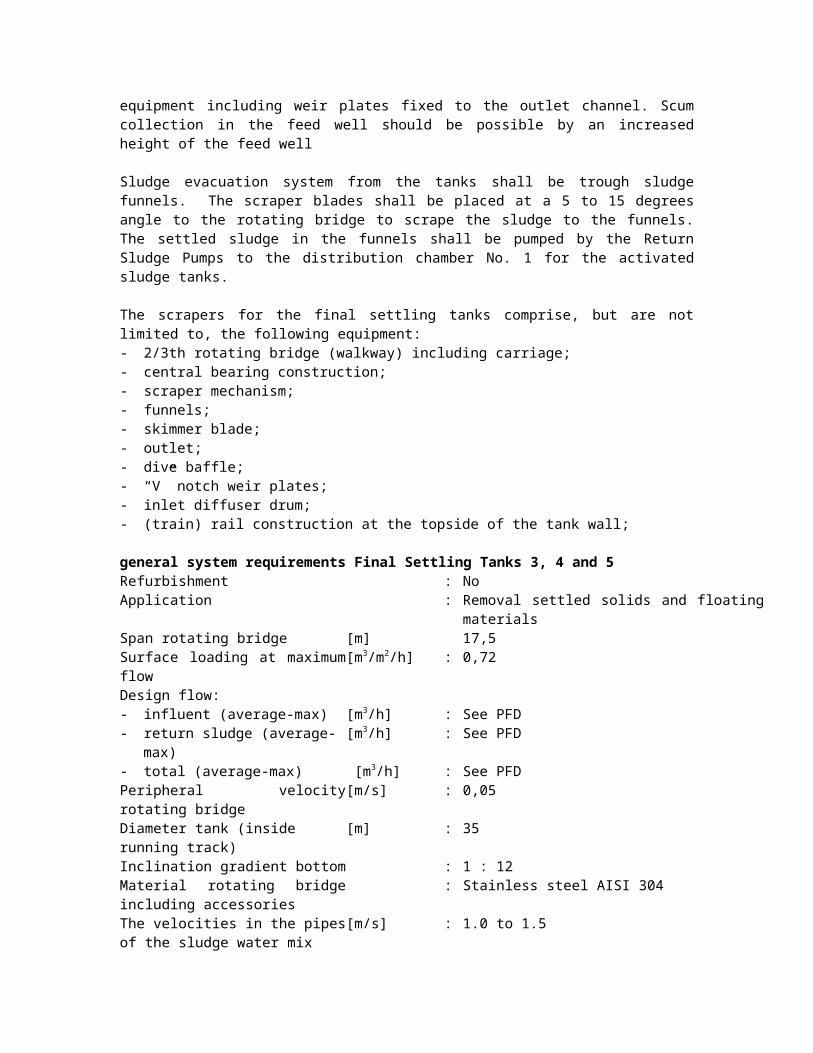
The installations include inlet pipes with tapered openings, sludge pipes to the sludge pumping station, rotating scrapers with all equipment including weir plates fixed to the outlet channel. Scum collection in the feed well should be possible by an increased height of the feed well
Sludge evacuation system from the tanks shall be trough sludge funnels. The scraper blades shall be placed at a 5 to 15 degrees angle to the rotating bridge to scrape the sludge to the funnels. The settled sludge in the funnels shall be pumped by the Return Sludge Pumps to the distribution chamber No. 1 for the activated sludge tanks.
The scrapers for the final settling tanks comprise, but are not limited to, the following equipment:- 2/3th rotating bridge (walkway) including carriage;- central bearing construction;- scraper mechanism;- funnels;- skimmer blade;- outlet;- dive baffle;- “V” notch weir plates;- inlet diffuser drum;
- (train) rail construction at the topside of the tank wall;
general system requirements Final Settling Tanks 3, 4 and 5Refurbishment : NoApplication : Removal settled solids and floating materialsSpan rotating bridge [m] 17,5Surface loading at maximum flow [m3/m2/h] : 0,72Design flow:- influent (average-max) [m3/h] : See PFD- return sludge (average-max) [m3/h] : See PFD- total (average-max) [m3/h] : See PFDPeripheral velocity rotating bridge [m/s] : 0,05Diameter tank (inside running track) [m] : 35Inclination gradient bottom : 1 : 12Material rotating bridge including accessories
: Stainless steel AISI 304
The velocities in the pipes of the sludge water mix
[m/s] : 1.0 to 1.5
The velocity at the tapered openings of the inlet pipes
[m/s] : < 0.7
1.13. Return sludge pumping station No 1The sludge is flowing by gravity from the Final Settling tanks No 1 and No 2 to an existing pump sump (return sludge pumping station No 1). The existing two sludge/water pumps shall be replaced by three (1 service, 1 stand-by) new pumps for return sludge being pumped to the Distribution Chamber 1 for the Activated Sludge Tanks.
general system requirements Return Sludge PumpNumber [pieces] : 1 duty and 1 standbyApplication : Return sludge from the final settling tanks 1 and
2 to distribution chamber 1.Type : Submersible centrifugal pumpType :Medium : SludgeEfficiency [%] : min. 60Capacity – flow: [m3/h] : See PFDCapacity – pressure [mwc] : to be defined by ContractorMaximum speed [1/min] : 1.500Material : pump casing: grey cast iron 20
impeller: chrome steel (material 4R)Location : Return sludge buildingSpecific requirements : - double mechanical seal;Motor : the pump/motor unit shall be suitable for variable
speed drive over the entire power curve of the pump.
1.14. Return sludge pumps final settling tanks 3, 4 and 5Three pumps shall be installed for return sludge being pumped to the Distribution Chamber 1 for the Activated Sludge Tanks.
general system requirements Return Sludge PumpNumber [pieces] : 3 x 2 (1 duty and 1 standby each tank)Application : Return sludge from the final settling tanks 3, 4,
and 5 to distribution chamber 1.Type : Axial pumpMedium : SludgeEfficiency [%] : min. 45Capacity – flow: [m3/h] : See PFDCapacity – pressure [mwc] : to be defined by ContractorMaximum speed [1/min] : 1.500Material : pump casing: grey cast iron 20
impeller: chrome steel (material 4R)Location : Return sludge buildingSpecific requirements : - mechanical seal;
- manometer and test cockMotor : - the pump/motor unit shall be suitable for
variable speed drive over the entire power curve of the pump.- one frequency controller for two pump/motor combinations.
1.15. Surplus sludge pumping stationTwo submersible pumps will transport surplus sludge from final settling tank 1&2 to the gravitational Sludge Thickener.
general system requirements Surplus Sludge PumpNumber [pieces] : 1 duty and 1 standbyApplication : Surplus sludge from the sludge pumping station
to the gravitational thickener.Type : Centrifugal pumpMedium : SludgeEfficiency [%] : min. 60capacity – flow: [m3/h] : See PFDcapacity – pressure [mwc] : to be defined by Contractormaximum speed [1/min] : 1500Material : pump casing: grey cast iron 20
impeller: chrome steel (material 4R)Location : Return sludge buildingspecific requirements : - mechanical seal;
- manometer and test cockMotor : the electric motor shall be direct driven.
The velocities in the pipes of the sludge water mixture shall be between 1.0 and 1.5 m/s.
1.16. Centrifugal compressors
1.16.1. DesignCentrifugal compressors shall be installed in the compressor building for the air supply to the Activated Sludge Tanks. Alternatively, lobe type air compressors are allowed to be applied conform the general mechanical specifications.
The compressors shall keep the pressure in the header within a narrow bandwidth (constant pressure loop). The volume flow will be controlled by means of inlet guide vanes and diffuser vanes of the compressor.
The capacity shall be controlled between 45 % - 100 % of the maximum capacity.
volume flow and reserve capacityApplication : Aeration of the activated sludge tanksNumber of compressors : 3Number compressors in operation:- Minimum : 1- Maximum : 3 dutyCapacity / compressor:- Minimum volume flow [mn
3/h] : 5.000- Maximum intake volume (0C,
1,013 bar)[mn
3/h] : 25.500
Electrical consumption [kWel] : app. 500Medium : atmospheric airIntake temperature:- Minimum [C] : -/- 40- Average [C] : 15- Maximum [C] : 35Intake pressure : atmospheric Relative humidity [%] :Maximum discharge pressure [bar absolute] : Contractor, app. 1,6
The compressor-installations for the fine bubble aeration comprise, but are not limited to, the following equipment:- compressors with drive unit, start-up unloading device, pressure relief valve;- frame with vibration isolators;- pressure protection;- piping and isolation piping;- inlet filter, inlet silencer, start-up silencer;- acoustic enclosure;- control valves, non return valves, start-up valves;- calculations, inspection and tests;- LCP-units and MCP-unit, connecting to all the necessary measurements- all necessary protections, limit switches, etc. to ensure a safely operating and protected
installation.
In case one compressor is out of operation, the other two shall be able to provide 70% of the required maximum capacity.
general system requirements CompressorsType : Single stage centrifugal compressor
Diffuser : YesPre-rotation : YesGearbox YesConstruction : - material rotor and shaft : Duraluminium, one piece- sealing labyrinth (male) Chrome steel- sealing labyrinth (female) AluminiumCooling : Oil coolingElectric motor :Construction : three-phase asynchronous motor, pole
reversibleStarting features : soft starting / star delta switchTherminal protection circuits : YesSeparate cooling fan : Yes
general system requirements Automatic valves for air supply Amount [pieces] : 9Type : Plate valve with V-NotchMaterial sealing : EPDMProtection class : IP 67Signals : - Max moment switches;
- Open/close signal- Valve position signal
: - Local manually actuatedSafety Protection by means of heating element and
thermo contactLocation : Outside on the activated sludge tanks
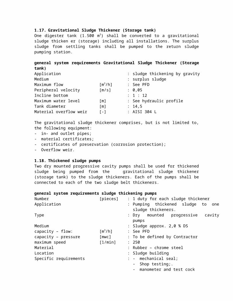
1.17. Gravitational Sludge Thickener (Storage tank)One digester tank (1.500 m3) shall be converted to a gravitational sludge thicken er (storage) including all installations. The surplus sludge from settling tanks shall be pumped to the return sludge pumping station.
general system requirements Gravitational Sludge Thickener (Storage tank)Application : sludge thickening by gravityMedium : surplus sludgeMaximum flow [m3/h] : See PFDPeripheral velocity [m/s] : 0,05Incline bottom : 1 : 12Maximum water level [m] : See hydraulic profileTank diameter [m] : 14,5Material overflow weir [-] : AISI 304 L
The gravitational sludge thickener comprises, but is not limited to, the following equipment:- in- and outlet pipes;- material certificates;- certificates of preservation (corrosion protection);- Overflow weir.
1.18. Thickened sludge pumpsTwo dry mounted progressive cavity pumps shall be used for thickened sludge being pumped from the gravitational sludge thickener (storage tank) to the sludge thickeners. Each of the pumps shall be connected to each of the two sludge belt thickeners.
general system requirements sludge thickening pumpsNumber [pieces] : 1 duty for each sludge thickenerApplication : Pumping thickened sludge to one sludge
thickeners.Type : Dry mounted progressive cavity pumpsMedium : Sludge approx. 2,0 % DScapacity – flow: [m3/h] : See PFDcapacity – pressure [mwc] : To be defined by Contractormaximum speed [1/min] : 250
Material : Rubber – chrome steelLocation : Sludge building Specific requirements : - mechanical seal;
- Shop testing;.- manometer and test cock
Motor : The electric motor shall be direct driven.
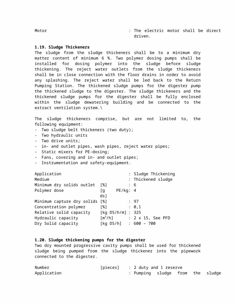
1.19. Sludge ThickenersThe sludge from the sludge thickeners shall be to a minimum dry matter content of minimum 6 %. Two polymer dosing pumps shall be installed for dosing polymer into the sludge before sludge thickening. The reject water outlets from the sludge thickeners shall be in close connection with the floor drains in order to avoid any splashing. The reject water shall be led back to the Return Pumping Station. The thickened sludge pumps for the digester pump the thickened sludge to the digester. The sludge thickeners and the thickened sludge pumps for the digester shall be fully enclosed within the sludge dewatering building and be connected to the extract ventilation system.\
The sludge thickeners comprise, but are not limited to, the following equipment:- Two sludge belt thickeners (two duty);- Two hydraulic units- Two drive units;- in- and outlet pipes, wash pipes, reject water pipes;- Static mixers for PE-dosing;- Fans, covering and in- and outlet pipes;- Instrumentation and safety-equipment.
Application : Sludge ThickeningMedium : Thickened sludgeMinimum dry solids outlet [%] : 6Polymer dose [g PE/kg ds] : 4Minimum capture dry solids [%] : 97Concentration polymer [%] : 0,1Relative solid capacity [kg DS/h/m] : 325Hydraulic capacity [m3/h] : 2 x 15, See PFDDry Solid capacity [kg DS/h] : 600 – 700
1.20. Sludge thickening pumps for the digesterTwo dry mounted progressive cavity pumps shall be used for thickened sludge being pumped from the sludge thickener into the pipework connected to the digester.
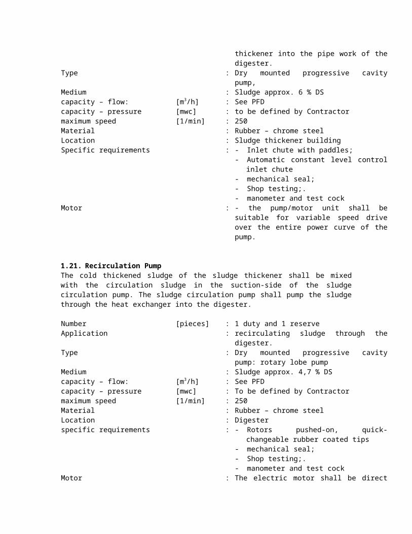
Number [pieces] : 2 duty and 1 reserveApplication : Pumping sludge from the sludge thickener into
the pipe work of the digester.Type : Dry mounted progressive cavity pump, Medium : Sludge approx. 6 % DScapacity – flow: [m3/h] : See PFDcapacity – pressure [mwc] : to be defined by Contractormaximum speed [1/min] : 250Material : Rubber – chrome steelLocation : Sludge thickener buildingSpecific requirements : - Inlet chute with paddles;
- Automatic constant level control inlet chute
- mechanical seal;- Shop testing;.- manometer and test cock
Motor : - the pump/motor unit shall be suitable for variable speed drive over the entire power curve of the pump.
1.21. Recirculation PumpThe cold thickened sludge of the sludge thickener shall be mixed with the circulation sludge in the suction-side of the sludge circulation pump. The sludge circulation pump shall pump the sludge through the heat exchanger into the digester.
Number [pieces] : 1 duty and 1 reserveApplication : recirculating sludge through the digester.Type : Dry mounted progressive cavity pump: rotary
lobe pump Medium : Sludge approx. 4,7 % DScapacity – flow: [m3/h] : See PFDcapacity – pressure [mwc] : To be defined by Contractormaximum speed [1/min] : 250Material : Rubber – chrome steelLocation : Digester specific requirements : - Rotors pushed-on, quick-changeable rubber
coated tips- mechanical seal;- Shop testing;.- manometer and test cock
Motor : The electric motor shall be direct driven.
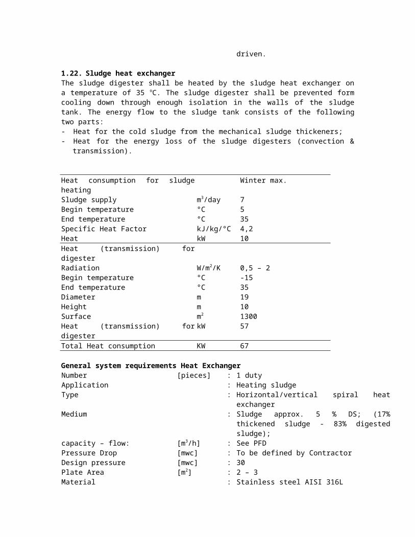
1.22. Sludge heat exchangerThe sludge digester shall be heated by the sludge heat exchanger on a temperature of 35 oC. The sludge digester shall be prevented form cooling down through enough isolation in the walls of the sludge tank. The energy flow to the sludge tank consists of the following two parts:- Heat for the cold sludge from the mechanical sludge thickeners;- Heat for the energy loss of the sludge digesters (convection & transmission). Heat consumption for sludge heating Winter max.Sludge supply m3/day 7Begin temperature °C 5End temperature °C 35Specific Heat Factor kJ/kg/°C 4,2Heat kW 10Heat (transmission) for digesterRadiation W/m2/K 0,5 – 2Begin temperature °C -15End temperature °C 35Diameter m 19Height m 10Surface m2 1300Heat (transmission) for digester kW 57
Total Heat consumption KW 67
General system requirements Heat ExchangerNumber [pieces] : 1 duty Application : Heating sludgeType : Horizontal/vertical spiral heat exchangerMedium : Sludge approx. 5 % DS; (17% thickened sludge
- 83% digested sludge);capacity – flow: [m3/h] : See PFDPressure Drop [mwc] : To be defined by ContractorDesign pressure [mwc] : 30Plate Area [m2] : 2 – 3Material : Stainless steel AISI 316L Location : Digester Specific requirements : 50 oC - 70 oC; temperature range heating water.
1.23. DigesterThe sludge in the digester shall be stirred by a horizontal mixer. The mixing arrangement shall ensure that the entire contents of the digester are uniformly agitated and no short-circuiting occurs. The horizontal mixer shall keep the sludge in the denitrification zones in suspension. The sludge shall spend at least 20 days in the digester.
general system requirements horizontal mixer in digesterMaterials- Propeller : Stainless steel AISI 316- bolts and nuts : Stainless steel AISI 316- motor casing : Stainless steel AISI 316Propellor speed [rpm] : Specific requirements : The mixer is removable out of the digester in
parts by a mobile crane.
The sludge digester will be protected by the following necessary safeties.
Safety cut–out devicesTemperature:- Minimum/Maximum [C] : from -30 to 35.Specific requirements : - hydraulic over- and under pressure device
(protected against frost);- hydraulic overflow protection by means of a
sludge siphon; - gas overpressure protection by means of a
sludge siphon.
1.24. Digested sludge pumping stationThree dry mounted progressive cavity pumps shall be used for thickened sludge, digested and DWTP-sludge being pumped to the Sludge Dewatering Station and to the sludge drying bed.
Each pump shall be connected to each of the two belt presses. If the belt presses are not available, the digested sludge shall be pumped to the sludge drying beds.
general system requirements Digested Sludge PumpsNumber [pieces] : 2 duty and 1 stand-by
(2 service and 1 stand-by for WWTP sludge;1 service for DWTP sludge and 1 service for WWTP sludge and 1 stand-by)
Application : Pumping thickened sludge or DWTP-sludge to drying bed and to the belt presses.
Type : Dry mounted progressive cavity pumpsMedium : Sludge approx. 2,0 % DS, and
: Drinking water sludge approx. 4 % DScapacity – flow: [m3/h] : See PFDcapacity – pressure [mwc] : to be defined by Contractormaximum speed [1/min] : 250Material : Rubber – chrome steelLocation : Thickened sludge building specific requirements : - mechanical seal;
- Shop testing;.- manometer and test cock
Motor : the pump/motor shall be suitable for variable speed drive over the entire power curve of the pump.
1.25. Drainage water pitTwo submersible pumps shall be used for drainage water/sludge being pumped to the Gravitational Sludge Thickener or to the return sludge building.
general system requirements Drainage Water PumpsNumber [pieces] : 1 duty and 1 standbyApplication : Drainage water from the sludge drying beds to
the storage tank.Type : centrifugal pumpMedium : Sludgecapacity – flow: [m3/h] : 20capacity – pressure [mwc] : to be defined by Contractormaximum speed [1/min] : 1.500Material : pump casing: grey cast iron 20
impeller: chrome steel (material 4R)Location : Return sludge buildingspecific requirements : - mechanical seal;
- testing in accordance with ISO 9906.- manometer and test cock
Motor : the electric motor shall be suitable over the entire power curve of the pump.
1.26. Sludge Storage Tank for Dumbrava Drinking Water Treatment Plant SludgeA mixer shall be placed in the storage tank (diameter 14,5 m) to keep in suspension the stored DWTP-sludge. The amount of mixers is indicative.
general system requirements MixersMedium : Anorganic sludge Propeller :- No. of blades : 3Jetring : NoMaterials- Propeller : Stainless steel AISI 316
- Bolts and nuts : Stainless steel AISI 316- motor casing : Stainless steel AISI 316Propellor speed [rpm] : max. 315Sealing : Maintainable double mechanical sealOil chamber : Water in oil detection with relaisAdditional : Leading beamMaterial leading beam : Stainless steel AISI 316
1.27. Sludge Dewatering
1.27.1. GeneralThe sludge from the digesters shall be dewatered by the belt presses (or decanters) to a minimum dry matter content of minimum 21 % by means of belt presses (or decanters).A polymer dosing system for solid polymer shall be installed. A complete standby line including polymer dosing shall be installed.
Conveyors shall transport the dewatered sludge to the Sludge Containers.
The reject water outlets from the dewatering equipment shall be in close connection with the floor drains in order to avoid any splashing. The reject water shall be led back to the Return Pumping Station.
The dewatering equipment and the dewatered sludge transportation systems shall be fully enclosed within the sludge dewatering building and within the container room and be connected to the extract ventilation system.
The sludge dewatering installation comprises, but is not limited to, the following equipment:- Two belt presses (two duty);- Hydraulic units- drive unit;- in- and outlet pipes, wash pipes, reject water pipes;- Static mixers for PE-dosing;
Additional general system requirements Belt presses
Digested sludgeApplication : Dewatering Medium : Digested sludge - Thickened sludge - DWTP
sludgeMinimum dry solids outlet [%] : 21Polymer dose [g PE/kg ds] : 9,5Minimum capture dry solids [%] : 97Concentration polymer [%] : 0,1Relative solid capacity [kg DS/h/m] : 325Hydraulic capacity [m3/h] : 2 x 5, see PFD. Dry Solid capacity [kg DS/h] : 487
1.27.2. Transport conveyors systemConveyors shall transport the dewatered sludge from the belt presses. Each belt press shall be connected to a conveyor system, filling up a container.
general system requirements Dewatered Sludge ConveyorsNumber [pieces] : 2 duty (50 % reserve capacity)
Application : Conveying dewatered sludge from the belt presses to the containers.
Type :Medium : Sludge > 21,0 %capacity – flow: [m3/h] : See PFDmaximum speed [m/s] : 0,5Material : Aisi 304Location : Dewatering building Specific requirementsMotor Dual speed motor.
1.27.3. Sludge containersThe dewatered sludge shall be conveyed into open containers. The containers shall be high enough to receive 10 tonnes of dewatered sludge from one outlet. The transportation system in the container area shall be enclosed as possible and connected to the extract ventilation system in the sludge dewatering building.
1.28. Polyelectrolyte preparation and dosing systemThere shall be two systems for polyelectrolyte (poly) preparation. The poly-electrolyte preparation system shall be also suitable for filling with liquid polymer. Each poly-electrolyte preparation system shall be suitable for preparing poly-electrolyte for both the sludge of the WWTP and the DWTP to the belt presses.
The chemical dosing system for poly comprise, but is not limited to, the following equipment:- poly storage / metering hopper;- poly solution mixing tanks;- dosing pumps;- pipe work, valves, fittings and application arrangement;- static mixer after each injection point;- kerbed and bund areas for poly preparation and supply;- process control instrumentation comprising upstream flow meter;- monitoring equipment.
polyelectrolyte storageThe poly is stored in bags of 20 kg in the storage area of the sludge dewatering building.
polyelectrolyte solution preparationThe poly to be used in dosing shall be prepared in batches. The poly powder shall be dispatched in a storage hopper, large enough to hold the total poly consumption for one shift. The unloading of the poly bags shall be designed in such a way that it can be carried out in an ergonomically sound manner.
time for preparation of the poly solution to take place at max. duty.
2 hours
strength of poly solutionSlurry make up accuracy +/- 5 %minimum residence time to follow manufacturers recommendationUnit size to suit process designNo of units for poly solution preparation 2 units;
poly electrolyte Dosing Pumppump type MeteringNumber [pieces] : 4 duty + 1 spare
Application : dosing of poly for belt presses and sludge thickeners
Medium : poly electrolyteTemperature [°C] : ambient temperaturestrength of dosing solution [%] :capacity: - minimum / maximum capacity [l/h] :Accuracy : +/- 5 % of set pointAvailability : 99 % in any 24 hour periodpump head to be determined by contractorLocation
1.29. Gas storage tankThe gas storage tank comprises, but is not limited to, the following equipment:- Gas storage tank with telescope and internal balloon;- Mechanical en hydraulic safety valves;- Instrumentation
Drain water in the gas storage tank shall be prevented by drains in the gas storage tank and drainage pits in the biogas pipeline to the gas burner, cogeneration units, and boiler.
Application : Conserving biogas Type : Dry gas storage tank (internal balloon)Medium : Biogas; 1.000 ppm H2S.Minimum volume [m3] : 150Normal Pressure [cm mwc] : 25Maximum Pressure [cm mwc] : 45Maximum pressure (hydraulic overpressure device)
[cm mwc] : 35
Maximum overfilling (mechanical overfilling device)
[%] : 103
Material tank [-] : Stainless steel AISI 316 L Material balloon [-] : Rubber, H2S-resistent
1.30. Gas BurnerThe total amount of biogas shall be burnt in de gas burner in case of emergency. The gas burner shall be a closed system burner; the flame shall not be visible.
Application : Burning biogasType : Closed gas burnerMedium : Biogas; 1.000 ppm H2S.Maximum flow [m3/h] : 75Minimum pressure [cm mwc] : 20Normal pressure [cm mwc] : 25Maximum pressure [cm mwc] : 35Material burner [-] : Stainless steel AISI 316 L Specific requirements [-] : Automatic control valves; instrumentation
The burner comprises, but is not limited to, the following equipment:- Closed gas burner;- Automatic control valve;- Instrumentation and safety.
1.31. Cogeneration unitsThe biogas shall be burned continuous in one of the two generators and the other shall be standby. Both cogeneration units shall run continuous on biogas and on a supply of natural gas in case of emergency. The generated heat shall be used for heating the sludge and heating the buildings. The emergency coolers shall cool down the gas motors in case of too much heat.
Normal situation
50% of the maximum
capacity
100% of the maximum
capacity
Supply of natural gas
Daily amount gas Nm3/day 1.500 2.200 1.500 2.112 Lower burning specific value MW/Nm3 23 23 23 32Total efficiency gasmotor % 30% 30% 30% 30%Bruto electricity kW 120 175 125 225Total bruto electricity kW 120 175 350
Additional requirementsApplication : Cogenerating heat and electricityType : Gas motor units with gear and generatorMedium : Biogas; 1.000 ppm H2S; Natural GasMaximum flow biogas [m3/h] : 92Minimum pressure [cm mwc] : 20Normal pressure [cm mwc] : 25Maximum pressure [cm mwc] : 35Specific requirements [-] : Automatic control valves for biogas and natural
gas; instrumentation; Low-NOx gas motor units
The cogeneration comprises, but is not limited to, the following equipment:- Two cogenerations units;- Heat exchangers for cooling water, oil, and stack gasses;- Heating water circuit with appendages, pumps and emergency coolers;- Stacks;- Lubricant oil installations with buffer tanks for oil and rejected oil.- The necessary instrumentation and safeties.
The cogenerations units shall be fully enclosed within the cogeneration unit building. The noise level outside the building shall be lower than 75 dB(a).
The cogeneration-units shall be tested in a commissioning test run of 4 weeks. The commissioning test run shall be renewed after a failure of the cogeneration unit, independent of the cause of the failure.
1.32. Sludge heating boilerThe sludge digester shall be heated around the year. Slightly drops of temperature will decrease the efficiency of the digestion process. A sludge heating boiler shall be installed as back-up service to sustain in emergency situations the temperature in the sludge digester. The boiler shall be designed to the worst case situation.
Natural gas shall be burned in the boiler for start-up of the sludge digestion in case of emergencies.
Daily amount gas Nm3/day 190 Lower burning specific value MW/Nm3 32Total efficiency gasmotor % 95%Heating capacity kW 67
Additional requirementsApplication : Generating heatType : Overpressure boiler Medium : Biogas; 1.000 ppm H2S; Natural GasMaximum flow biogas [m3/h] : 10Minimum pressure [cm mwc] : 20Normal pressure [cm mwc] : 25Maximum pressure [cm mwc] : 35Specific requirements [-] : Automatic control valves for biogas and natural
gas; instrumentation; dual low-nox-burners
The boiler comprises, but is not limited to, the following equipment:- Boiler units with burners, equipped for biogas and natural gas;- Stack- Instrumentation and safeties. - Auxilary equipment: gas filter, water filter, valves, expansion vessel, circulating pumps (2
duty +1 standby), filling pump, treated water station (automated).
A boiler shall be installed according to Romanian regulation ISCIR PT C-1-2003 about installation and use of the hot water and steam boilers. The contractor shall ensure that the heating system complies with all ISCIR regulations regarding “D category” boilers (especially C-1 and A-1), fire-fighting regulations, specific norms for gas use I 6-96 and general rules for heating installations according to I 13-94. The boilers shall be equipped with automated burners for gas (biogas and natural). The construction of boilers has to comply with the limits of “D category” according to ISCIR C-1.
1.33. Services
1.33.1. Heating systemThe heating system shall be completely renewed for the waste water plant. The contractor shall install a complete fully functional system. The capacity of the thermal heaters shall be calculated by the Contractor based on the heat/cold loads in each building to be heated as well as ventilation requirements. The required temperatures in the different buildings are:- Screening Station (5°C). - Sludge Dewatering Station (5°C).- Administration Building (22°C).- Blower (5°C).- Container building (5°C).- Sludge pumping Station (5°C).- Workshop (22°C)
The piping for hot water inside the buildings shall be insulated. The connection pipes between buildings shall be pre-insulated and mounted underground in accordance with the specifications of the pipe supplier. All pipes for hot water shall be seamless steel pipes.
The functioning of the whole heating station shall be fully automated.
1.33.2. VentilationVentilation systems are required for the following buildings (the figure between brackets is the required number of air changes per hour):- Screening Station (6 x), - Sludge Dewatering Station (3x).- Administration Building (1x).- Blower (6x).- Container building (3x).- Sludge pumping Station (3x).- Gas condense cellar (5x).- Workshop (2x)
1.33.3. Internal potable water supply and non-potable water supplyThe contractor shall renew the complete systems for non-potable water as well as potable water for ordinary use. Infrastructure of the systems shall be the same as currently in use plus the added users from the improved WWTP design.
Non-potable water shall be used for washing the following equipment:- The Sludge Dewatering Station to be used for flushing the belt presses.- The Screenings Station for washing the screenings.- The Grit Chamber and Grease Chambers for washing the grit.- to be used thinning the polyelektrolyte concentrate for the belt presses and the sludge
thickeners.- to be used for flushing the sludge thickeners 1&2;
A complete booster pump set including two (1 stand-by) dry mounted centrifugal pumps, valves, pressure control tank, necessary filter and piping system for supply of wash water shall be installed, including level control.
1.33.4. Air conditioning systemsThe Contractor shall install a split-type air conditioning system in the laboratory room in the administrative building. The air conditioner shall be sized to heat load and size of the room (smallest laboratory room). A minimum temperature of 22 º C. shall be attainable at all times.
1.33.5. Sump pumpsSump pumps shall be installed in all rooms with pipelines containing water or sludge:- Administration Building.- Sludge Dewatering Building.- Thickened Sludge pumping building.- Gas condense cellar.- Sludge pumping Station. The sump pumps shall be connected to the site sewerage system.
1.34. Site sewerage The reject water shall be led to the site sewerage system. The sewer pipelines shall be large enough for gravity flow to the waterline in maximum operating situation. Otherwise, sewer pumps shall be installed for pumping the internal flow to the waterline.
1.35. Lifting ArrangementsAll Plant, materials housings, etc., that may be manually handled during the course of normal operations or maintenance shall be provided with lifting arrangements according to the following:- above 20 kg - Provision of suitably rated lifting arrangement;
- above 500 kg - Provision of lifting beam with manual chain block;- above 1 tonne - Provision of overhead crane with manual chain block.
Lifting arrangements and Plant shall be load tested on site after installation. Load test certificates shall be supplied for all lifting Plant.
1.36. Air deliveryThe necessary compressed process air shall be supplied to the equipment. Compressed air for tools shall be supplied to: - The administration building.- Workshop.