Embed Size (px)
Citation preview

CALTRANS SLURRY/MICRO-SURFACE MIX DESIGN PROCEDURE MONTHLY PROGRESS REPORT CONTRACT 65A0151 FUGRO PROJECT 3139
MONTHLY PROGRESS REPORT Slurry/Micro-Surface Mix Design Procedure
September 2005 To: T. Joe Holland, CALTRANS Contract No.: CALTRANS 65A0151 Contractor: Fugro Consultants LP Contract Period: June 30, 2003 – Nov. 30, 2007 Prepared By: Jim Moulthrop, Principal Investigator Date Prepared: October 17, 2005 PROJECT OVERVIEW The overall goal of this research is to improve the performance of slurry seal and micro-surfacing systems through the development of a rational mix design procedure, guidelines, and specifications. Phase I of the project has two major components: 1) the first consists of a literature review and a survey of industry/agencies using slurry and micro-surfacing systems, 2) the second deals with the development of a detailed work plan for Phases II and III. In Phase II, the project team will evaluate existing and potential new test methods, evaluate successful constructability indicators, conduct ruggedness tests on recommended equipment and procedures, and prepare a report that summarizes all the activities undertaken under the task. In Phase III, the project team will develop guidelines and specifications, a training program, and provide expertise and oversight in the construction of pilot projects intended to validate the recommended design procedures and guidelines. All activities of the study will be documented in a Final Report. NOTE: New information for the current month is notated by double-lines to the left of text, tables, or figures. PHASE I—LITERATURE SEARCH AND WORK PLAN DEVELOPMENT Task 1 Literature Review and Industry Survey—Completed The literature review process is complete with all sources of information on the design and use of micro-surfacing and slurry seals reviewed and summarized in Chapter 2 of the Phase I Report. The three survey questionnaires were included in the August 2003 monthly report and the results were summarized in the Phase I Report. Task 2 Work Plans for Phases II and III—Completed The Phase II Work Plan was included in Chapter 3 of the Phase I Report. The Phase III Work Plan was included in Chapter 4 of the Phase I Report. All activities of Phase I are complete. The results are included in the Phase I Interim Report that was submitted to CALTRANS in March 2004.
1

CALTRANS SLURRY/MICRO-SURFACE MIX DESIGN PROCEDURE MONTHLY PROGRESS REPORT CONTRACT 65A0151 FUGRO PROJECT 3139
PHASE II—MIX DESIGN PROCEDURE DEVELOPMENT A videoconference was held on September 15, 2005 with 10 States, FHWA representatives, and members of the research team participating. The team presented progress on Phase II and Phase III activities and responded to questions from the participants. The following major issues/questions were raised:
1. What is the estimated cost/time to build and monitor a pilot project? 2. States re-iterated the need for a field acceptance test/procedure 3. What is the cost of the new laboratory equipment? 4. What are the guidelines regarding the use of a tack coat? 5. The current requirements for traffic on the pilot projects are too high and should be
reduced 6. According to the proposed pilot project layout, the Control sections are located between
Slurry System sections and therefore a “lip” or edge will be created before and after each Control section. This difference in elevation may be the cause for unwanted damage to the slurry system sections due to the use of snowplows during winter.
In response to these issues, the team is recommending:
1. The actual cost of building and facilitating the monitoring and testing of a pilot project will vary depending on local Agency conditions. Agencies should consider the following costs:
a. Construction crew and equipment b. Traffic control (during construction and monitoring/testing activities) c. Cost of the slurry system products
The total cost of a typical pilot project, which is an existing project that will be built in 2006 and the test sections will be added to the work, for example, will cost about $20,000. Higher costs can be expected if just a test section is constructed.
2. As mentioned during the videoconference, the team will evaluate different possible field acceptance tests and procedures; however, it is to early to make recommendations in that respect. More information on the candidate filed tests and sampling procedures will be included in the next monthly report.
3. The cost of the new laboratory equipment is estimated to be less than $10,000.
4. The team has not yet studied this aspect extensively (it was not included in the original
scope of work) but we can make recommendations for tack application as a part of the Strawman specification. Currently, tack is normally used on airfield taxiways and runways.
5. As mentioned by some of the participants at the videoconference, slow setting slurry
systems are generally placed on lower traffic roads and the minimum 10,000 ADT criteria recommended by the team might restrain the Agency’s options for placing pilot projects on lower traffic roads. In response to this comment the team recommends a minimum 1,000 ADT to be used as the lower limit for project selection.
2
CALTRANS SLURRY/MICRO-SURFACE MIX DESIGN PROCEDURE MONTHLY PROGRESS REPORT CONTRACT 65A0151 FUGRO PROJECT 3139
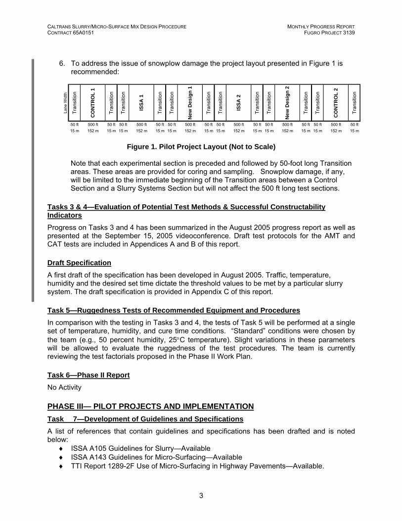
6. To address the issue of snowplow damage the project layout presented in Figure 1 is recommended:
Lane
Wid
th
Tran
sitio
n
CO
NTR
OL
1
Tran
sitio
n
Tran
sitio
n
ISSA
1
Tran
sitio
n
Tran
sitio
n
New
Des
ign
1
Tran
sitio
n
Tran
sitio
n
ISSA
2
Tran
sitio
n
Tran
sitio
n
New
Des
ign
2
Tran
sitio
n
Tran
sitio
n
CO
NTR
OL
2
Tran
sitio
n
50 ft 500 ft 50 ft 50 ft 500 ft 50 ft 50 ft 500 ft 50 ft 50 ft 500 ft 50 ft 50 ft 500 ft 50 ft 50 ft 500 ft 50 ft15 m 152 m 15 m 15 m 152 m 15 m 15 m 152 m 15 m 15 m 152 m 15 m 15 m 152 m 15 m 15 m 152 m 15 m
Figure 1. Pilot Project Layout (Not to Scale)
Note that each experimental section is preceded and followed by 50-foot long Transition areas. These areas are provided for coring and sampling. Snowplow damage, if any, will be limited to the immediate beginning of the Transition areas between a Control Section and a Slurry Systems Section but will not affect the 500 ft long test sections.
Tasks 3 & 4—Evaluation of Potential Test Methods & Successful Constructability Indicators Progress on Tasks 3 and 4 has been summarized in the August 2005 progress report as well as presented at the September 15, 2005 videoconference. Draft test protocols for the AMT and CAT tests are included in Appendices A and B of this report. Draft Specification A first draft of the specification has been developed in August 2005. Traffic, temperature, humidity and the desired set time dictate the threshold values to be met by a particular slurry system. The draft specification is provided in Appendix C of this report. Task 5—Ruggedness Tests of Recommended Equipment and Procedures In comparison with the testing in Tasks 3 and 4, the tests of Task 5 will be performed at a single set of temperature, humidity, and cure time conditions. “Standard” conditions were chosen by the team (e.g., 50 percent humidity, 25°C temperature). Slight variations in these parameters will be allowed to evaluate the ruggedness of the test procedures. The team is currently reviewing the test factorials proposed in the Phase II Work Plan. Task 6—Phase II Report No Activity PHASE III— PILOT PROJECTS AND IMPLEMENTATION Task 7—Development of Guidelines and Specifications A list of references that contain guidelines and specifications has been drafted and is noted below:
♦ ISSA A105 Guidelines for Slurry—Available ♦ ISSA A143 Guidelines for Micro-Surfacing—Available ♦ TTI Report 1289-2F Use of Micro-Surfacing in Highway Pavements—Available.
3

CALTRANS SLURRY/MICRO-SURFACE MIX DESIGN PROCEDURE MONTHLY PROGRESS REPORT CONTRACT 65A0151 FUGRO PROJECT 3139
♦ Report contains: o Methods and Materials Specifications o Quality Control and Assurance Tests (including field cohesion and vane shear
tests) o Quality Control Guidelines (including materials acceptance tests and mixture
design verification) o A Checklist o Usage Guidelines.
♦ ISSA Inspector’s Manual—Available ♦ Caltrans Maintenance Technical Advisory Guide Final Draft—Available ♦ The ISSA Workshop Folder—Available
The guidelines and specifications will be a concise collection, presented in AASHTO format. This is one area of Phase III where the team can work at present. At the end of Phase II, the document will be appended with findings and recommendations relative to the new tests developed in Phase II. Task 8—Workshop Training Program/Pre-Construction Module The team agreed that work could commence in several chapters of the Reference Manual to be developed under this task. The Reference Manual will be a comprehensive, textbook-like document with background information, explanations, and pertinent information on the design and use of slurry systems. A first draft of the Reference Manual has been included in Appendix A of the August 2005 progress report. Task 9—Pilot Projects/Procedure Validation The team developed guidelines for selecting pilot projects to be used by State agencies. The proposed pilot project layout contains six different sections:
♦ A control section placed using the ISSA current procedure. ♦ A bare section (do nothing) ♦ Improved mix design (using the method developed in Phase II), Replicate 1 ♦ Another contractor-based control (ISSA design). ♦ Another bare section. ♦ Improved mix design (using the method developed in Phase II), Replicate 2
The final version of the Guidance Document was included in Appendix A of the October 2004 and April 2005 progress reports. The document was forwarded to the participant State agencies and other agencies interested in participating in the pilot project study. Following discussions at the September 2005 videoconference, the required minimum Task 10—Final Report No Activity
4

CALTRANS SLURRY/MICRO-SURFACE MIX DESIGN PROCEDURE MONTHLY PROGRESS REPORT CONTRACT 65A0151 FUGRO PROJECT 3139
NEXT MONTH’S WORK PLAN The activities planned for next month are listed below.
♦ Coordinate with CALTRANS personnel on an as-needed basis. ♦ Continue with Phase II and Phase III activities.
PROBLEMS / RECOMMENDED SOLUTIONS All problems with the acquisition of the test equipment have been overcome. Significant progress has been made during the month of August. FINANCIAL STATUS The Financial Summary Table shows the estimated expenses incurred during the reporting period and to the present from the inception of the contract. Testing has been removed as a separate Cost Element item because it is a subcontractor task activity. The Financial Summary Chart illustrates total expenditures by month for the project. cc: Jim Moulthrop Glynn Holleran Dragos Andrei David Peshkin Gary Hicks Carol Goldman Stephen Seeds Charles Antle
5

CALTRANS SLURRY/MICRO-SURFACE MIX DESIGN PROCEDURE MONTHLY PROGRESS REPORT CONTRACT 65A0151 FUGRO PROJECT 3139
Financial Summary Table – Estimated Expenses for Reporting Period Cost Element
Current Month Expenditures, $ Cumulative Costs, $
Direct Labor 3,754 51,926 Overhead 5,708 78,928 Consultants/Subcontractors MACTEC 0 23,063 APTech 12,743 101,505 CEL 0 16,013 Travel 730 10,026 Communication 0 26 Materials/Supplies/Shipping 0 2,970 Fee 1,019 14,388
Phase II Retention (2,395) 18,673
Total 21,556 310,806
MONTHLY PROGRESS REPORTFINANCIAL CHART
0
100
200
300
400
500
600
700
800
900
1000
J J A S O N D J F M A M J J A S O N D J F M A M J J A S O N D J F M A M J J A S O N D J F M A M J J A S O N D
Time, Months
Tota
l Exp
endi
ture
, $ (T
hous
ands
)
Actual,$Planned,$
CALTRANS Slurry/Micro-Surface Mix Design Procedure
Contractor - Fugro Consultants LPFugro Project 3139
$921,500
2003 2004 2005 2006 2007
Financial Summary Chart – Total Expenditures by Month
6

CALTRANS SLURRY/MICRO-SURFACE MIX DESIGN PROCEDURE MONTHLY PROGRESS REPORT CONTRACT 65A0151 FUGRO PROJECT 3139
APPENDIX A DRAFT AUTOMATED MIXING TEST (AMT)
LABORATORY TEST PROTOCOL

CALTRANS SLURRY/MICRO-SURFACE MIX DESIGN PROCEDURE MONTHLY PROGRESS REPORT CONTRACT 65A0151 FUGRO PROJECT 3139
DRAFT Proposed Method of Test for
Constructability of Asphalt Emulsions and Aggregate Mixture Systems [Automated Mixing Test (AMT)] AASHTO Designation: DRAFT Proposed Test Method 001 (PTM 003) Rev 1 1.0 SCOPE 1.1 The test method covers measurement of the constructability of slurry surfacing materials
once basic ratios of components have been established. By automatic and constant recording of the complete torque- measurement-curve, the mixing curve is showing indicating each variation during the breaking process. The evaluation takes place under tightly defined controlled conditions and the apparatus provides an automatic report of results.
1.2 The main parameters that are measured are:
• Mixing Torque (Mix index) • Mixing time • Spreading time • Maximum Torque (Spread Index)
1.3 The test method is in development. 1.4 The values stated in SI units are to be regarded as the standard. 2.0 REFERENCED DOCUMENTS 2.1 ISSA TB 113, Trial Mix Procedure for Slurry Seal Design. 2.2 Thin Lift in Cold-Applied Micro-Surfacing, Instructions for the Electric Mixing Test,
(Translated from German). 2.3 Labsoftworld software Versions 4.0 and 4.5. 2.4 Eurostar Power Visc manual. 2.5 Velp mixing stirrer manual.
Caltrans PTM 001 (PTM 003) REV-1 / Page 1 010/12/2005

CALTRANS SLURRY/MICRO-SURFACE MIX DESIGN PROCEDURE MONTHLY PROGRESS REPORT CONTRACT 65A0151 FUGRO PROJECT 3139
3.0 SUMMARY OF METHOD 3.1 The asphalt emulsion, aggregate, setting additives, and water are the components of the
mix. The mix components, at the prescribed temperature, are weighed into test container. The other components will be added as described by the mix design or through pre-testing using the hand mixing method, ISSA TB 113. The asphalt emulsion and water (with additive) are put into the container after being conditioned at the test. The mixing cup is centered under the stirrer and lowered to 1.5mm form cup bottom. Then the rotation of the stirrer is started manually and maintained at 50rpm for 5 sec. The test is started via the PC. The mix is stirred until it either breaks or 10 minutes have elapsed.
3.2 A loss mass below 100 g is representative of a high cohesion slurry seal or micro-
surfacing mix. A loss of mass of 300 g represents an average cohesion. When the loss of mass is close to 600 g, it is expected that the slurry seal or micro-surfacing mix will not resist traffic.
3.3 It is also noted when the mixture breaks by visual observation. At this point the mixture
fragments into parts and free liquid may be observed. 3.4 If the mix does not break the test is terminated at 10 minutes mixing and observations
made as greater than or less than the specification level. 4.0 SIGNIFICANCE AND USE 4.1 This test method will measure compatibility and setting parameters of asphalt emulsions
and mineral aggregates. 4.2 This procedure is suggested for establishing design criteria of the mix system. In
addition, it provides a means of quality control during the production of asphalt emulsion, mineral aggregates, and additives.
4.3 This method facilitates research and development of new combinations of raw materials. 4.4 This method documents the temperature influences on the consistency of the mixed
materials. 4.5 This method measures the affect of compositional changes on mixing. 5.0 APPARATUS 5.1 Eurostar Power Visc 5.2 Velp propeller mixer 5.3 Mixing Bowls as defined made for stainless steel
Caltrans Strawman 2.0 / Page 2 09/01/2005

CALTRANS SLURRY/MICRO-SURFACE MIX DESIGN PROCEDURE MONTHLY PROGRESS REPORT CONTRACT 65A0151 FUGRO PROJECT 3139
5.4 Balance accurate to 0.1 g 5.5 PC capable of running Labworldsoft V4.5 software (Windows 2000 or higher), Excel
spreadsheet. 5.6 Thermometer calibrated 0-50C 5.7 Spatulas 5.8 Constant temperature cabinet or room 6.0 MATERIALS 6.1 Aggregates: Sample representative portions of aggregates used for slurry seal mix or
micro-surfacing mix. Use material of the type, grade, and source proposed for the construction Project work. Aggregates shall be dried at 60°C to a constant mass and cooled to the prescribed test temperatures prior to performing the test.
6.2 Bitumen emulsions maintained at the test temperature and representative of the material
to be used in the project. 6.3 Additives both solid and liquid that shall be use din the project. 6.4 Water-Distilled drinking water with a pH between 6.0 and 7.0 shall be used. 7.0 PROCEDURE 7.1 Maintain the aggregate, emulsion, water, and additives at the test temperature
(10C, 25C and 35C). 7.2 Set up the Eurostar ready for test with the PC ready on the correct
measurement configuration. 7.3 The amounts of materials shall be quantified by a mix design, from TB113 or in
a matrix to determine specific mix effects. 7.4 Add 300g of aggregate into the mixing bowl. 7.5 Add the required amount of solid additives and mix well by hand. 7.6 Add pre-wet water and liquid additive and mix well by hand.
Caltrans Strawman 2.0 / Page 3 09/01/2005

CALTRANS SLURRY/MICRO-SURFACE MIX DESIGN PROCEDURE MONTHLY PROGRESS REPORT CONTRACT 65A0151 FUGRO PROJECT 3139
7.7 Add emulsion and quickly blend through the aggregate-5-10 sec. 7.8 Place in apparatus. 7.9 Start mixer manually and mix 5-10 sec. 7.10 Start test and monitor torque. 7.11 Switch off test at 10 minutes or when torque rises to a maximum and then falls
off, which ever comes first. 8.0 REPORT Report the following: 8.1 Mixing Torque 8.2 Mixing Time 8.3 Spread Time 8.4 Maximum Torque 8.5 Breaking time 8.6 If the mixture mixes beyond 10 minutes without increasing in torque or breaking, note
results as greater than or less than. 9.0 PRECISION AND BIAS This method is in development.
Caltrans Strawman 2.0 / Page 4 09/01/2005

CALTRANS SLURRY/MICRO-SURFACE MIX DESIGN PROCEDURE MONTHLY PROGRESS REPORT CONTRACT 65A0151 FUGRO PROJECT 3139
APPENDIX B DRAFT COHESION ABRASION TEST (CAT)
LABORATORY TEST PROTOCOL

CALTRANS SLURRY/MICRO-SURFACE MIX DESIGN PROCEDURE MONTHLY PROGRESS REPORT CONTRACT 65A0151 FUGRO PROJECT 3139
DRAFT Proposed Method of Test for
Measurement of Cohesion Build Up and Wearing Qualities of Asphalt Emulsions and Aggregate Mixture Systems [Cohesion Abrasion Test (CAT)] AASHTO Designation: DRAFT Proposed Test Method 003 (PTM 003) 1.0 SCOPE 1.1 The test method covers measurement of the wearing qualities of slurry seal and micro-
surfacing mixture systems under wet abrasion conditions at different levels of cure. The method is also suitable for measuring early cohesion of slurry and microsurfacing mixes under different cure conditions.
1.2 The test method is applicable to mixes after the formulation of the slurry seal or micro-
surfacing and, its set additives and water contents have been adjusted to prepare homogenous flowing consistency.
1.3 The method may be used to assess the stripping potential of aggregates in early life. 1.4 The test method is in development. 1.5 The values stated in SI units are to be regarded as the standard. 2.0 REFERENCED DOCUMENTS 2.1 ASTM D 3910-80a, Practice for Design, Testing, and Construction of Slurry Seal. 2.2 ASTM D 6372, Practice for Design, Testing and Construction of Micro-Surfacing. 2.3 ISSA TB 100, Test Method for Wet Track Abrasion of Slurry Surfaces. 2.4 SCREG Surface Cohesion Test for Slurry Systems, C. Deneuvillers, ISSA 37th Annual
Meeting, Mexico, 1999. 2.5 SSA TB 113 2.6 AMT Mixing Test
B-1

CALTRANS SLURRY/MICRO-SURFACE MIX DESIGN PROCEDURE MONTHLY PROGRESS REPORT CONTRACT 65A0151 FUGRO PROJECT 3139
3.0 SUMMARY OF METHOD 3.1 Asphalt emulsion, aggregate, setting additives, and water are the components of the
mix. Mixes are made up as per the method described into patties. 3.2 The proportions of the components will be derived after optimizing the binder content
from previous testing as recommended in the mix design. The mix components, at the prescribed temperature, humidity, compacted/uncompacted and day/night conditions, are cured for specific time periods. After curing, the specimen is placed in a circular pan on the planetary type mechanical mixer. Water is placed over the sample; in some cases the sample may be soaked in water before hand. The specimen surface comes in contact with the abrading dual wheel head. The wheels move across the surface in a planetary movement and abrasion occurs for 60 seconds. After the end of abrasion, the specimen debris is washed off. The sample is dried in an oven at 60C absorbent paper and this final weight is compared to the dry weight of a sample abrasion.
3.3 A loss mass below 100 g is representative of a high cohesion slurry seal or micro-
surfacing mix. A loss of mass of 100-300 g represents an average cohesion. When the loss of mass is close to 400 g, it is expected that the slurry seal or micro-surfacing mix will not resist traffic.
4.0 SIGNIFICANCE AND USE 4.1 The test method will measure early stage abrasion resistance and also abrasion
resistance of cured mixtures. 4.2 The test method can quantify the influence of some formulation parameters on setting
time and cohesion build up (such as variations of the mix components or the environmental temperature and/or humidity conditions while laying).
4.3 System classification of long-term moisture susceptibility may be determined by the use
of varying wet-curing conditions. 4.4 Correlations between laboratory results and field performance will be explored during the
development of the test method. 5.0 APPARATUS 5.1 Planetary type mechanical mixer, such as Hobart N-50 equipped with a dual wheel
abrasion head, quick-clamp mounting plate, and flat bottom metal pan. 5.1.1 Wheels: 100 mm diameter with 22 mm contact width. 5.1.2 Wheel hardness of 75 and 95 (durometer reading) foot. 5.1.3 Abrasion head should weigh between 1100 g and 1150 g.
Caltrans Strawman 2.0 / Page 2 09/01/2005

CALTRANS SLURRY/MICRO-SURFACE MIX DESIGN PROCEDURE MONTHLY PROGRESS REPORT CONTRACT 65A0151 FUGRO PROJECT 3139
5.2 Stainless steel or aluminum mounting plates 2mm in thickness and 286 mm in diameter. 5.3 Suitable specimen molds of specified depth (6.35mm is standard) and specified inside
diameter: 279 mm for the N-50 mixer. A raised lip mold is preferred but a flat surface polymethyl methacrylate mold is satisfactory.
5.4 Mold strike-off apparatus, 25 mm diameter x 350 mm wooden dowel. 5.5 Scales, with capacity of 2000.0 g, accurate to +/- 0.1 g. 5.6 Wooden prop block or device to support the pan and mounting plate assembly during
the test. 5.7 Suitable rust-resistant mixing containers, spoons. 5.8 Constant temperature water bath controlled at specified temperatures. 5.9 Forced air draft ovens and environmental chambers, maintaining specific curing
temperatures. 5.10 Humidity chamber for curing in high and low humidity conditions. 5.11 Means of compacting specimens: Standard Vialit test roller. 6.0 MATERIALS 6.1 Aggregates-Sample representative portions of aggregates used for slurry seal mix or
micro-surfacing mix. Use material of the type, grade, and source proposed for the construction work. Aggregates shall be dried at 60°C to a constant mass and cooled to prescribed test temperatures prior to performing the test.
6.2 Asphalt Emulsion-Use material of the type, grade, and source proposed for the
construction work. Asphalt emulsion shall be maintained at prescribed temperature for testing.
6.3 Setting Additives-Use liquid, powdered, or liquid (undiluted or diluted) setting additives
where specified from the mix design or through pre-testing. 6.4 Water: Distilled drinking water with a pH between 6.0 and 7.0 shall be used. 7.0 PREPARATION OF TEST SPECIMEN 7.1 Maintain test temperatures of the aggregate, emulsion, water, and additives at the
prescribed testing temperature. 7.2 The amounts of material components will be quantified as described by the mix design
or through determinations from pre-testing using the electric mixing method. In order to
Caltrans Strawman 2.0 / Page 3 09/01/2005

CALTRANS SLURRY/MICRO-SURFACE MIX DESIGN PROCEDURE MONTHLY PROGRESS REPORT CONTRACT 65A0151 FUGRO PROJECT 3139
minimize delays, all additions of materials, should be pre-determined and pre-weighed prior to starting the stirrer.
7.3 Split or quarter a sufficient amount of the dried aggregate to obtain 1200g in one quarter. 7.4 Brush about 5 g of tack coat emulsion (use the same emulsion as is used in the mixture)
on to the disc so it is evenly covered. Allow to dry completely. 7.5 Weigh 1200 g of aggregate into a mixing bowl. Using a spoon mix in prescribed amount
of dry set additive to the aggregate and mix for 1 minute or until uniformly distributed. Add the predetermined amount of water and mix again for 1 minute or until uniformly distributed. Add the liquid set additive to the mix and mix for 1 minute or until uniformly distributed. Finally, add the predetermined asphalt emulsion and mix for 1 minute
7.6 Center the opening in the specimen mold on the 286 mm diameter disc. Immediately
pour the slurry onto the roofing felt disc. 7.7 Screed the slurry level with the top of the mold with a minimum of manipulation. Using a
sawing motion of the dowel even out the surface. Discard excess material. 7.8 After the prescribed curing conditions, record the weight of the specimen immediately
before abrasion. Make another mixture and cast onto a pre-weighed disc of roofing felt. Cure this sample I the oven at 60C for 12 hours top obtain a sample dry weight.
8.0 TEST PROCEDURE 8.1 If required, place the sample in a constant temperature water bath for 1 hour. Place the
specimen in the 330 mm diameter flat bottom pan. Clamp the specimen to the pan and mounting plate by tightening the quick clamps.
8.2 Cover the specimen with 6.35 mm depth of water at a specified temperature. 8.3 Lift the mounting plate until the surface of the specimen comes in contact with the
abrading wheel. 8.4 Switch to the low speed of the Hobart machine. Abrade for 60 seconds. 8.5 Rinse the loose debris with 1 liter of water and dry specimen with an absorbent paper
towel. Record the final weight. 8.6 Dry sample I an oven for 12 hrs at 60C. 9.0 REPORT Report the following information: 9.1 Aggregate: percent used, type of aggregate, source and the date received for testing.
Caltrans Strawman 2.0 / Page 4 09/01/2005

CALTRANS SLURRY/MICRO-SURFACE MIX DESIGN PROCEDURE MONTHLY PROGRESS REPORT CONTRACT 65A0151 FUGRO PROJECT 3139
9.2 Asphalt emulsion: percent used, type of emulsion, source and the date received for testing.
9.3 Set additive(s): percent used, type, source, and the date received for testing. 9.4 Percent of water used to initially wet the aggregate, if needed. 9.5 Curing conditions: temperature, humidity, day/night conditions, aging, and soaking time. 9.6 Testing conditions: machine used, running time. 9.7 Abrasion test result as a total loss of mass and as g/cm2 on both a wet and dry basis. 9.8 Observation of failure and stripping of aggregate in test 10.0 PRECISION AND BIAS This method is in development. At present, there is no precision and bias statement for
this method.
Caltrans Strawman 2.0 / Page 5 09/01/2005

CALTRANS SLURRY/MICRO-SURFACE MIX DESIGN PROCEDURE MONTHLY PROGRESS REPORT CONTRACT 65A0151 FUGRO PROJECT 3139
APPENDIX C DRAFT SLURRY SYSTEMS SPECIFICATION

CALTRANS SLURRY/MICRO-SURFACE MIX DESIGN PROCEDURE DRAFT MIX DESIGN REFERENCE MANUAL CONTRACT 65A0151 FUGRO PROJECT 3139
Specification for
SLURRY SURFACING SYSTEM Caltrans: Strawman 4.0 1.0 DESCRIPTION 1.1 This work consists of furnishing and placing a slurry surfacing system meeting the
requirements of this specification. The mixture shall consist of a combination of an emulsified asphalt, mineral aggregate, mineral filler, water, and other necessary additives, mixed and placed on the pavement surface in accordance with the dimensions shown on the plans.
1.2 Any modified ingredient shall be milled or blended into the asphalt or blended into the
emulsifier solution prior to the emulsification process. The emulsion supplier shall provide a certificate that the emulsion supplied to the project conforms to the requirements of Table 1.
TABLE 1 Asphalt Emulsion Requirements
PROPERTY Test Method Minimum Maximum
Viscosity, Saybolt Furol @ 77° F, Seconds AASHTO T 59 20 100 Storage Stability test, one day, % AASHTO T 59 - 1 Particle Charge test AASHTO T 59 Positive Sieve Test, % AASHTO T 59 - 0.1
Tests on Distillation Oil distillate, by volume or emulsion, % residue AASHTO T 59 60 -
Tests on Residue Penetration, 77° F, 100g, 5 sec AASHTO T 49 55 90 Ductility, 77° F 5 cm/min, cm AASHTO T 51 70 - Solubility in trichlorethylene, % AASHTO T 44 97.5 Softening Point, minimum AASHTO T 53 135 ° F
1.3 Asphalt Emulsion
The asphalt emulsion used shall conform to the requirements of Table 1. Any modified ingredient shall be milled or blended into the asphalt or blended into the emulsifier solution prior to emulsification process. The emulsion supplier shall provide a certificate that the emulsion supplied to the project conforms to the requirements of Table 1.
1.4 Aggregate
Mineral aggregate shall meet the quality requirements in Table 2 and meet the grading requirements in Table 3. The grade of aggregate shall be as specified on the project plans
Caltrans Strawman 2.0 / Page 1 09/01/2005

CALTRANS SLURRY/MICRO-SURFACE MIX DESIGN PROCEDURE DRAFT MIX DESIGN REFERENCE MANUAL CONTRACT 65A0151 FUGRO PROJECT 313
TABLE 2 Aggregate Quality Requirements
Note * The abrasion test is to be run on the parent aggregate
Test Test Method Requirement Sand Equivalent, min AASHTO T 176 65 Los Angeles Abrasion, loss at 500 rev., max* AASHTO T 96 35 Percentage of Crushed Particles, minimum AASHTO T 100 Magnesium sulfate soundness, max. loss, %, 4 cycles AASHTO T 104 20 Micro-Duval, loss, %** AASHTO Report
** The Micro-Duval is to be run on the project stockpile aggregate
TABLE 3 Aggregate Grades Grade US Sieve Size Passing by Weight, % Job Mix Formula
Tolerance Limits, %+ - ⅜ 9.5 mm 100 5 #4 4.75 mm 70-90 5 #8 2.36 mm 45-70 5
#16 1.16 mm 28-50 5 #30 600μm 19-34 3 #50 330 μm 12-25 3
A
#200 75 μm 5-15 2 ⅜ 9.5 mm 100 5 #4 4.75 mm 94-100 5 #8 2.36 mm 65-90 5
#16 1.18 mm 40-70 5 #30 600 μm 25-50 3 #50 330 μm 18-30 3
B
#200 75 μ 5-15 2 ⅜ 9.5 mm 100 #4 4.75 mm 100 5 #8 2.36 mm 90-100 5
#16 1.16 mm 65-90 5 #30 600μm 40-65 5 #50 330 μm 25-42 4
C
#200 75 μm 10-20 2 1.5 Stockpile and Storage If the mineral aggregates are stored or stockpiled, they must be handled in a manner
that will prevent segregation and contamination. The aggregate will be accepted at the job site stockpile or when loading into the units for delivery to the laydown machine. The stockpile shall be accepted based on five gradation tests according to AASHTO T2. If the average of five tests is within the gradation tolerances, the materials will be accepted. If the test results indicate that the material is outside the gradation limits, the material will be removed from the stockpile site or blended with other aggregate from the stockpile to achieve an acceptable product.
Materials used for blending shall meet the requirements of Table 3 and shall be blended
in an acceptable manner to assure a consistent product. Blending will require a new mix design. The aggregate shall be passed over a ⅜-in (9.5-mm) scalping screen prior to transfer to the laydown machine to remove oversize material.
Caltrans Strawman 2.0 / Page 2 09/01/2005

CALTRANS SLURRY/MICRO-SURFACE MIX DESIGN PROCEDURE DRAFT MIX DESIGN REFERENCE MANUAL CONTRACT 65A0151 FUGRO PROJECT 313
1.6 Water and Additives Water shall be potable and free from harmful soluble salts or other contaminants. The
slurry surfacing mixture shall be homogeneous during and following mixing and spreading and possess sufficient stability to prevent premature breaking in the spreading equipment. Additives may be added to the emulsion mix or any of the component materials to provide control of the setting characteristics of the mixture. They must be included as part of the mix design and be compatible with the other components of the mix.
1.7 Mineral Filler Mineral filler may be used in the mixture, shall be introduced into the mineral aggregate,
and shall be an approved brand of non-air entrained Portland cement or hydrated lime that is free from lumps. Visual inspection and supplier certification are required. The amount of mineral filler to be added shall be part of the mix design process and shall be considered as part of the aggregate gradation. If additional consistency is required during the placement of the mixture, a +/- one percent change in mineral filler will be permitted without requiring a new mix design.
2.0 SLURRY SURFACING SYSTEM 2.1 Prior to the beginning of work, the contractor shall submit a proposed mix design for
approval to the contracting agency. A laboratory capable of performing the tests that are noted in Table 4 shall perform the mix design. The proposed slurry surfacing mixture shall conform to the requirements of Table 4. The percentages of each individual material shall be shown on the design form.
2.2 Field adjustments may be necessary once the work is under way but individual materials
shall be within the limits contained in Table 5.
Caltrans Strawman 2.0 / Page 3 09/01/2005
CALTRANS SLURRY/MICRO-SURFACE MIX DESIGN PROCEDURE DRAFT MIX DESIGN REFERENCE MANUAL CONTRACT 65A0151 FUGRO PROJECT 313
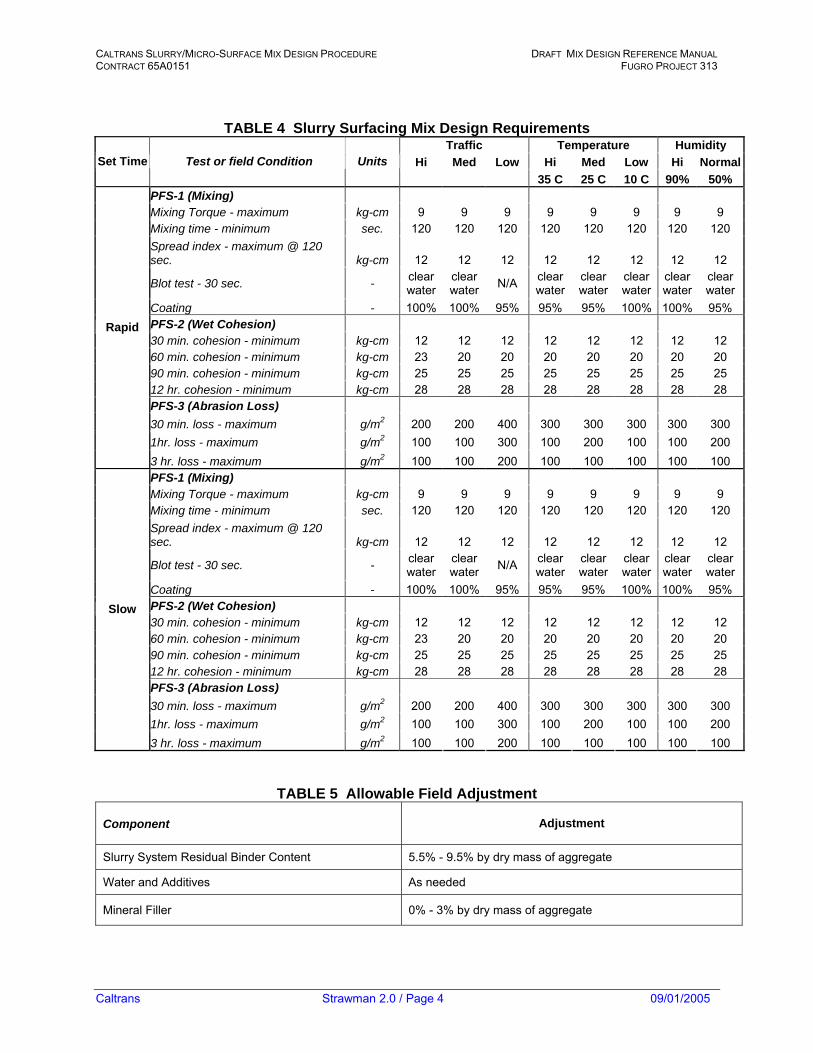
TABLE 4 Slurry Surfacing Mix Design Requirements Traffic Temperature Humidity
Hi Med Low Hi Med Low Hi NormalSet Time Test or field Condition Units 35 C 25 C 10 C 90% 50%
PFS-1 (Mixing) Mixing Torque - maximum kg-cm 9 9 9 9 9 9 9 9 Mixing time - minimum sec. 120 120 120 120 120 120 120 120 Spread index - maximum @ 120 sec. kg-cm 12 12 12 12 12 12 12 12
Blot test - 30 sec. - clear water
clear water N/A clear
waterclear water
clear water
clear water
clear water
Coating - 100% 100% 95% 95% 95% 100% 100% 95% PFS-2 (Wet Cohesion) 30 min. cohesion - minimum kg-cm 12 12 12 12 12 12 12 12 60 min. cohesion - minimum kg-cm 23 20 20 20 20 20 20 20 90 min. cohesion - minimum kg-cm 25 25 25 25 25 25 25 25 12 hr. cohesion - minimum kg-cm 28 28 28 28 28 28 28 28 PFS-3 (Abrasion Loss) 30 min. loss - maximum g/m2 200 200 400 300 300 300 300 300 1hr. loss - maximum g/m2 100 100 300 100 200 100 100 200
Rapid
3 hr. loss - maximum g/m2 100 100 200 100 100 100 100 100 PFS-1 (Mixing) Mixing Torque - maximum kg-cm 9 9 9 9 9 9 9 9 Mixing time - minimum sec. 120 120 120 120 120 120 120 120 Spread index - maximum @ 120 sec. kg-cm 12 12 12 12 12 12 12 12
Blot test - 30 sec. - clear water
clear water N/A clear
waterclear water
clear water
clear water
clear water
Coating - 100% 100% 95% 95% 95% 100% 100% 95% PFS-2 (Wet Cohesion) 30 min. cohesion - minimum kg-cm 12 12 12 12 12 12 12 12 60 min. cohesion - minimum kg-cm 23 20 20 20 20 20 20 20 90 min. cohesion - minimum kg-cm 25 25 25 25 25 25 25 25 12 hr. cohesion - minimum kg-cm 28 28 28 28 28 28 28 28 PFS-3 (Abrasion Loss) 30 min. loss - maximum g/m2 200 200 400 300 300 300 300 300 1hr. loss - maximum g/m2 100 100 300 100 200 100 100 200
Slow
3 hr. loss - maximum g/m2 100 100 200 100 100 100 100 100
TABLE 5 Allowable Field Adjustment
Component Adjustment
Slurry System Residual Binder Content 5.5% - 9.5% by dry mass of aggregate
Water and Additives As needed
Mineral Filler 0% - 3% by dry mass of aggregate
Caltrans Strawman 2.0 / Page 4 09/01/2005

CALTRANS SLURRY/MICRO-SURFACE MIX DESIGN PROCEDURE DRAFT MIX DESIGN REFERENCE MANUAL CONTRACT 65A0151 FUGRO PROJECT 313
3.0 APPLICATION RATE 3.1 The slurry surfacing shall be of the proper consistency at all times in order to provide the
application rate required by the plans and specifications to meet the surface conditions. The average single application rate, if not specified, shall be in accordance with the requirements of Table 6.
TABLE 6 Application Rates
Aggregate Grade Facility Application Rate
Primary and Interstate Routes 15-30 lbs./yd2 8.1-16.2 kg/m2
A Wheel Ruts See Section 6. (d). 2
B Urban, Residential Streets, Airfield Runways & Taxiways 10-20 lbs./yd2 5.4-18.6 kg/m2
C Parking Areas, Residential Streets, Airfield Runways & Taxiways 8-12 lbs./ yd2 3.6-5.4 kg/m2
4.0 QUALITY ASSURANCE 4.1 Prior to the beginning of the project, the contractor shall provide an orientation session
for project personnel, a test strip, and project documentation. 4.2 Orientation Session for Project Personnel The contractor shall provide a minimum 45-minute orientation session with the project
personnel to discuss the construction process, materials control, materials measurement requirements of the project, and any unique project conditions that need to be addressed. This session may be waived at the direction of the engineer.
4.3 Test Strip With the coordination of the owner, the contractor shall arrange for a test strip to be
constructed on or near the project site under as reasonable as possible the anticipated placement conditions of time of day, temperature, and humidity. The test strip shall be 300 to 500 feet (91 m-152 m) in length and shall be constructed with the job mix proportions, materials, and equipment to be used on the project. Adjustments to the mix design shall be permitted provided they do not exceed the values stated in Table 4. The test strip shall be evaluated by the owner to determine if the mix design and placement techniques are acceptable once the mixture has set and cured. If modifications to the mix design in excess of the values noted in Table 4 are necessary, a new mix design shall be prepared and another test strip constructed. The cost of the materials and placement of the rejected test strip shall be borne by the contractor including any removal costs.
Caltrans Strawman 2.0 / Page 5 09/01/2005

CALTRANS SLURRY/MICRO-SURFACE MIX DESIGN PROCEDURE DRAFT MIX DESIGN REFERENCE MANUAL CONTRACT 65A0151 FUGRO PROJECT 313
4.4 Project Documentation After the project is underway, the contractor shall, on a daily basis, furnish the owner
project documentation that includes the total amount of material delivered to the project and the total amount placed through the mixing machine from the dial gauges. The owner’s agent shall verify the dial gauge readings and material weights delivered and this information will be used to independently verify the mix proportions.
5.0 QUALITY ASSURANCE 5.1 Prior to the beginning of the project, the contractor shall provide an orientation session
for project personnel, a test strip, and project documentation. 5.2 Orientation Session for Project Personnel
The contractor shall provide a minimum 45-minute orientation session with the project personnel to discuss the construction process, materials control, materials measurement requirements of the project, and any unique project conditions that need to be addressed. This session may be waived at the direction of the engineer.
5.3 Test Strip
With the coordination of the owner, the contractor shall arrange for a test strip to be constructed on or near the project site under as reasonable as possible the anticipated placement conditions of time of day, temperature, and humidity. The test strip shall be 300 to 500 feet (91 m-152 m) in length and shall be constructed with the job mix proportions, materials, and equipment to be used on the project. Adjustments to the mix design shall be permitted provided they do not exceed the values stated in Table 4. The test strip shall be evaluated by the owner to determine if the mix design and placement techniques are acceptable once the mixture has set and cured. If modifications to the mix design in excess of the values noted in Table 4 are necessary, a new mix design shall be prepared and another test strip constructed. The cost of the materials and placement of the rejected test strip shall be borne by the contractor including any removal costs.
5.4 Project Documentation
After the project is underway, the contractor shall, on a daily basis, furnish the owner project documentation that includes the total amount of material delivered to the project and the total amount placed through the mixing machine from the dial gauges. The owner’s agent shall verify the dial gauge readings and material weights delivered and this information will be used to independently verify the mix proportions.
6.0 CONSTRUCTION REQUIREMENTS 6.1 Weather Limitations
Slurry systems shall not be applied if either the pavement temperature or the air temperature is below 50º F (10º C) and falling. No material shall be applied when there is the eminent possibility of rain or if the finished product is subject to freezing within 24 hours. The mixture shall not be applied when weather conditions prolong opening to traffic beyond a reasonable time.
Caltrans Strawman 2.0 / Page 6 09/01/2005

CALTRANS SLURRY/MICRO-SURFACE MIX DESIGN PROCEDURE DRAFT MIX DESIGN REFERENCE MANUAL CONTRACT 65A0151 FUGRO PROJECT 313
6.2 Mixing Equipment
The materials shall be mixed in a specifically designed piece of equipment, either truck mounted for small applications and residential work, or continuous run machine for larger projects such as highways and airports. The machine must be a continuous-flow mixing unit able to accurately proportion and deliver the aggregate, emulsified asphalt, mineral filler, additives, and water to a continuous flow mixing chamber. The machine shall have sufficient storage capacity for all the mixture ingredients to maintain an adequate supply to the mixing chamber.
6.3 Proportioning Devices
Individual volume or weight controls for proportioning each material shall be provided and properly identified. These devices are used in material calibration and may be used to determine the material output on demand.
6.4 Spreading Equipment
The mix shall be agitated and spread uniformly in a specially designed box that is equipped with twin shafted paddles or spiral augers that are permanently fixed to the box. A front seal shall be provided to insure there is no loss of the mixture. The rear seal shall be adjustable and act as the final strike-off of the mixture. The spreader box and rear strike-off shall be designed so that a uniform mixture is delivered to the rear strike-off. The box shall be able to be shifted laterally to compensate for variability in the geometry of the pavement.
6.4.1 Secondary Strike-Off
Where required on the plans, the spreading equipment shall be equipped with a secondary strike-off to provide a satisfactory surface texture. It shall be capable of having the same leveling adjustments as the spreader box.
6.4.2 Rut Box
When the plans require that wheel ruts, depressions, and utility cuts, and others be filled prior to placing the finished wearing course, material shall be placed with a specially designed rut filling spreader box when rut depths are greater than ½ inch (12.7 mm). For ruts of less than ½ inch (12.7 mm), a full width scratch course using the conventional spreader box is acceptable. Rut boxes are typically designed to be 5 feet (1.8 m) or 6 feet (1.8 m) wide. Where ruts exceed 1½ inches (39 mm), multiple passes with the rut box are necessary. All rut filling should be allowed to cure under traffic for at least 24 hours before the final surface course is placed. Mixtures for filling ruts, depressions, utility cuts, and others shall meet the requirements of Type A as specified in Table 3.
6.5 Machine Calibration
Each unit to be used for the placement of slurry systems shall be calibrated in the presence of the owner’s representative. Previous calibration covering the same materials to be used may be acceptable provided no more than 60 days has elapsed. The calibration documentation shall include an individual calibration of each material at
Caltrans Strawman 2.0 / Page 7 09/01/2005

CALTRANS SLURRY/MICRO-SURFACE MIX DESIGN PROCEDURE DRAFT MIX DESIGN REFERENCE MANUAL CONTRACT 65A0151 FUGRO PROJECT 313
various settings that can be related to the metering devices on the machine. No equipment shall be permitted to work on the project without a completed calibration.
6.6 Workmanship
When placing slurry surfacing mixtures, the longitudinal and transverse joints shall be uniform, neat in appearance, and not contain material build-up or uncovered areas. Longitudinal joints shall be placed on lane lines, edge lines, or shoulder lines and shall have a maximum overlap of 3 inches (75 mm). Longitudinal joints shall be straight in appearance along the centerline, lane lines, shoulder lines, and edge lines. The finished surface shall have a uniform texture free from excessive scratch marks, tears, or other surface defects. A total of four tear marks are considered to be excessive when they exhibit the following criteria:
• ½ inch (13 mm) wide or wider. • 6 inches (150 mm) or more long. • Within 100 yd2 (85 m2) of any mark that conforms to one of the following criteria:
o 1 inch (25 mm) wide or wider. o 4 inches (100 mm) long.
The contractor is expected to produce neat and uniform longitudinal and transverse joints. Transverse joints shall be constructed as butt-type joints. Joints are acceptable if there is no more than a ½-inch (13-mm) vertical space for longitudinal joints, and no more than 3/8 inches (9 mm) for a transverse joint between the pavement surface and a 4-foot (1.2 m) straightedge placed perpendicular on the joint.
6.7 Surface Preparation
Immediately before applying the slurry surfacing, the pavement surface shall be cleaned of all loose material, vegetation, and other objectionable materials. Any standard cleaning procedure is acceptable. If water is used, cracks shall be permitted to dry thoroughly before applying the slurry mixture. A suitable method shall be used to cover service entrances (i.e., manhole covers, valve boxes). No dry aggregate, either spilled from the mixing machine or existing on the pavement surface, will be permitted.
6.8 Tack Coat
If required on the plans, a tack coat consisting of one part SS or CSS emulsion and three parts water shall be applied with a standard distributor. The distributor shall be capable of applying the diluted emulsion at the rate of 0.5 to 0.10 gallons/yd2 (0.16-0.32 liters/m2). The tack shall be allowed to cure sufficiently before the application of the slurry surfacing.
6.9 Cracks
Existing cracks on the surface of the pavement shall be treated with an acceptable material well in advance of the placement of the slurry surfacing. The surface of the crack filling material shall be 1/8 inch (3.175 mm) below the surface of the roadway.
6.10 Handwork
In areas where the placement equipment cannot work because of space limitations, these areas should be surfaced using hand tools to provide a complete and uniform
Caltrans Strawman 2.0 / Page 8 09/01/2005

CALTRANS SLURRY/MICRO-SURFACE MIX DESIGN PROCEDURE DRAFT MIX DESIGN REFERENCE MANUAL CONTRACT 65A0151 FUGRO PROJECT 313
coverage. These areas should be cleaned and lightly dampened before placing the mix. The finished texture shall be uniform and have a neat appearance as nearly as possible to that produced by the spreader box.
6.11 Application
The surface of the pavement shall be pre-wetted by fogging ahead of the spreader box. The rate of application shall be adjusted during the placement based on the temperature, texture of the pavement surface, and humidity.
6.12 Clean Up All areas including service entrances, gutters, and intersections shall be cleaned of the
slurry surfacing on a daily basis as well as any debris associated with the placement. 7.0 METHOD OF MEASUREMENT 7.1 Area
On small projects, less than 50,000 yd2 (41,805 m2), the method of measurement and payment shall be based on the area covered, which is measured in square feet, square yards, or square meters.
7.2 Weight
On projects larger than 50,000 yd2 (41,805 m2), the measurement is based on the quantity of aggregate (tons or metric tons) and emulsified asphalt (gallons or liters) that are used. The aggregate is measured by the actual weight delivered to the project laydown site or is weighed at the stockpile with certified scales. Delivery tickets or printed weights shall be used for measurement. The emulsified asphalt will be measured by certified tickets for each load delivered to the project. Unused or returned emulsion will be deducted.
8.0 BASIS OF PAYMENT 8.1 The slurry surfacing shall be paid for by the unit area or the quantities of the aggregate
and emulsified asphalt used and accepted on the project. The price shall include furnishing, mixing, and applying the slurry surfacing; labor, equipment, tools, mix design, test strips, surface preparation, and incidentals necessary to complete the project.
Caltrans Strawman 2.0 / Page 9 09/01/2005


![DEVELOPMENT OFA MIX DESIGN PROCESS FOR COLD-IN …publications.iowa.gov/2505/1/tr474phase1[1].pdf1.2 Emulsion and water content ... Laboratory mix design procedure ... Development](https://img.pdfslide.net/doc/110x75/5ad2a6877f8b9a482c8ca89d/development-ofa-mix-design-process-for-cold-in-1pdf12-emulsion-and-water.jpg)