Embed Size (px)
DESCRIPTION
Code
Citation preview

D.V .Bhavanna Rao M.Tech., F.I.E.,
Retired R&B Chief Engineer
E-mail: [email protected]
Phone: +919494440202
for all my presentations, please visit
http://aproadbuildqa.blogspot.com

Important Publications for Rural Roads
1.Specifications for Rural Roads, MORD
(2004).
2.Rural Roads Manual IRC:SP:20-2002.
3. MORD Quality Assurance Handbook
for Rural Roads Volume I and II :2007
4.Hill Road Manual: IRC:SP:48-1998.
5.IRC:SP: 72-2007: Guidelines for design of flexible pavements for low volume Rural Roads
6. IRC:SP: 62-2004 Guidelines for Design of Rigid Pavements for Rural Roads

300 Earth works
301 Embankment construction 302 Earth work in cutting 303 Subgrade construction 304 Rock cutting 305 Excavation for structures 306 Flyash Embankment construction 307 Surface drains 308 Soil erosion and sedimentation control 309 Turfing with sods 310 Seeding and mulching
400 Granular Sub-bases, Bases & surfacings
401 Granular Sub - Base 402 Gravel/Soil – Aggregates base and surface course 403 Lime treated soil for improved Sub – Grade / sub base 404 Cement treated Soil sub-base/ base 405 Water Bound macadam sub-base/ bases/surfacing 406 Wet Mix Macadam base 407 Shoulder construction 408 Local materials for road construction 409 Lime – Flyash stabilised soil sub-base 410 Industrial wastes for road construction 411 Crusher – Run macadam base 412 Brick soling 413 Stone set pavement

500 Bituminous costruction
501 Preparation of surface. 502 Prime coat over Granular Base 503 Tack coat 504 Bituminous Macadam 505 Built-up spray grout 506 Modified penetration macadam 507 Surface dressing 508 20mm Thick premix carpet 509 Mix seal surfacing 510 Seal coat 511 Supply of stone aggregates for pavement courses 512 Modified bitumen

Other Important Sections in MORD Specifications 200 Site Clearance 600 Brickwork for Structures 700 Stone masonry for Structures 800 Concrete for Structures 900 Formwork and surface finish for structures 1000 Steel reinforcement 1100 Pipe culverts 1200 RCC slab culverts and minor bridges 1400 Cement Concrete Causeways 1500 Cement Concrete Pavement 1600 Hill Road Construction 1800 Quality Control 1900 Maintenance

Important Sections in IRC:SP:20-2002
Chapter 1: Planning and Alignment Chapter 2: Geometric Design Standards Chapter 3: Climate and Environment Chapter 4: Road Materials Chapter 5: Pavement design Chapter 6: Road Drainage Chapter 7: Culverts and Small Bridges Chapter 8: Construction and Specifications Chapter 9: Use of Waste materials Chapter 10: Quality Control in Construction Chapter 11: Maintenance Chapter 12: Souces of Finance

Typical cross section in plain and rolling terrain

eeeeEeeee
Sub-Grade (300mm)
Sub base Base
Embankment
shoulder shoulder
Typical Pavement Cross Section
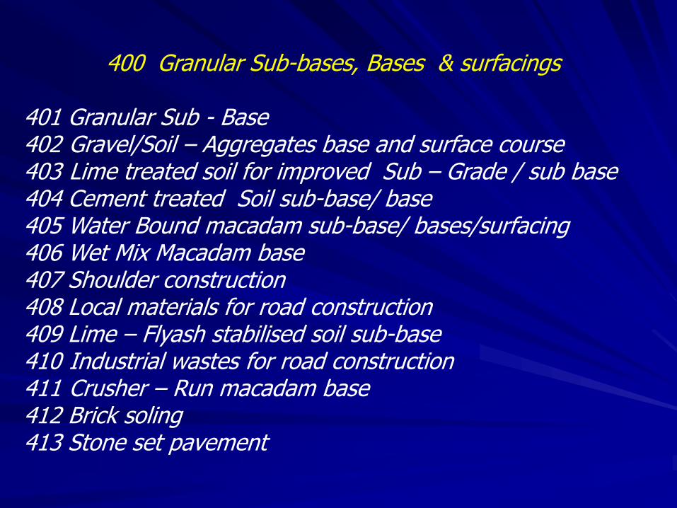
Pavement thickness chart as per IRC: SP 20 2002

Pavement thickness as per IRC: SP 20 2002
CBR Crust 0 to 15
CVPD
15 to 45
CVPD
45 to 150
CVPD
150 to 450
CVPD
2%
Base 150 150 225 225
Sub base 275 365 370 455
3%
Base 150 150 150 225
Sub base 200 265 330 320
4%
Base 150 150 150 150
Sub base 125 200 260 315
5%
Base 150 150 150 150
Sub base 100 165 210 260
6%
Base 150 150 150 150
Sub base 60 115 150 175

Pavement thickness as per IRC: SP 20 2002
CBR Crust 0 to 15
CVPD
15 to 45
CVPD
45 to 150
CVPD
150 to
450
CVPD
7
Base 150 150 150 150
Sub base 60 115 150 175
10%
Base 150 150 150 150
Sub base 30 70 85 125
15%
Base 150 150 150 150
Sub base nil 30 50 75
20%
Base 150 150 150 150
Sub base nil nil 30 50

Cumulative
ESAL
applications
Bituminous
Surface
treated
WBM/CRMB
Base of
gravel,
WBM,
CRMB of
CBR not
less than
100%
Gravel Base
of CBR not
less than
80%
Granular
Sub Base of
CBR not
less than
20%
Modified
soil or sub
grade of
CBR not
less than
10%
10,000 to
30,000 Nil nil 200 nil 100
30,000 to
60,000 75 nil 150 nil 100
60,000 to
1,00,000 75 100 nil 100 100
1,00,000 to
2,00,000 75 100 nil 100 150
2,00,000 to
3,00,000 75 100 nil 150 150
3,00,000 to
6,00,000 75 100 nil 225 150
6,00,000
to10,00,000 75 150 nil 200 225
IRC: SP 72 – 2007, Pavement Design Catalogue. CBR = 2%

Cumulative
ESAL
applications
Bituminous
Surface
treated
WBM/CRMB
Base of
gravel,
WBM,
CRMB of
CBR not
less than
100%
Gravel Base
of CBR not
less than
80%
Granular
Sub Base of
CBR not
less than
20%
Modified
soil or sub
grade of
CBR not
less than
10%
10,000 to
30,000 Nil nil 200 nil nil
30,000 to
60,000 nil nil 275 nil nil
60,000 to
1,00,000 75 100 nil 150 nil
1,00,000 to
2,00,000 75 100 nil 100 100
2,00,000 to
3,00,000 75 100 nil 100 150
3,00,000 to
6,00,000 75 150 nil 100 150
6,00,000
to10,00,000 75 150 nil 150 150
T04%IRC: SP 72 – 2007, Pavement Design Catalogue. CBR = 3 to 4%

Cumulative
ESAL
applications
Bituminous
Surface
treated
WBM/CRMB
Base of
gravel,
WBM,
CRMB of
CBR not
less than
100%
Gravel Base
of CBR not
less than
80%
Granular
Sub Base of
CBR not
less than
20%
Modified
soil or sub
grade of
CBR not
less than
10%
10,000 to
30,000 Nil nil 175 nil nil
30,000 to
60,000 nil nil 250 nil nil
60,000 to
1,00,000 nil nil 275 nil nil
1,00,000 to
2,00,000 75 100 nil 125 nil
2,00,000 to
3,00,000 75 100 nil 150 nil
3,00,000 to
6,00,000 75 100 nil 100 100
6,00,000
to10,00,000 75 150 nil 100 100
T04%IRC: SP 72 – 2007, Pavement Design Catalogue. CBR = 5 to 6%
Cumulative
ESAL
applications
Bituminous
Surface
treated
WBM/CRMB
Base of
gravel,
WBM,
CRMB of
CBR not
less than
100%
Gravel Base
of CBR not
less than
80%
Granular
Sub Base of
CBR not
less than
20%
Modified
soil or sub
grade of
CBR not
less than
10%
10,000 to
30,000 Nil nil 150 nil nil
30,000 to
60,000 nil nil 175 nil nil
60,000 to
1,00,000 nil nil 225 nil nil
1,00,000 to
2,00,000 75 100 nil 100 nil
2,00,000 to
3,00,000 75 100 nil 125 nil
3,00,000 to
6,00,000 75 100 nil 150 nil
6,00,000
to10,00,000 75 150 nil 150 nil
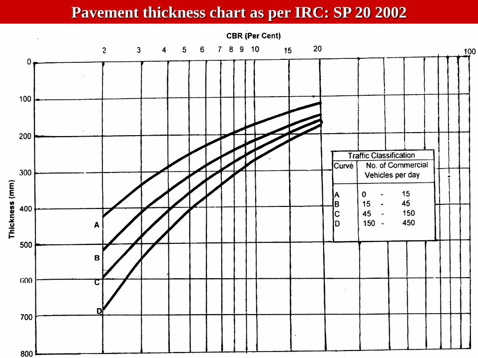
T04%IRC: SP 72 – 2007, Pavement Design Catalogue. CBR = 7 to 9%

Cumulative
ESAL
applications
Bituminous
Surface
treated
WBM/CRMB
Base of
gravel,
WBM,
CRMB of
CBR not
less than
100%
Gravel Base
of CBR not
less than
80%
Granular
Sub Base of
CBR not
less than
20%
Modified
soil or sub
grade of
CBR not
less than
10%
10,000 to
30,000 Nil nil 125 nil nil
30,000 to
60,000 nil nil 150 nil nil
60,000 to
1,00,000 nil nil 175 nil nil
1,00,000 to
2,00,000 75 150 nil nil nil
2,00,000 to
3,00,000 75 100 nil 100 nil
3,00,000 to
6,00,000 75 100 nil 125 nil
6,00,000
to10,00,000 75 150 nil 125 nil
T04%IRC: SP 72 – 2007, Pavement Design Catalogue. CBR = 10 to 15%

Embankment Construction
1.Embankment with natural earth
2. Embankment with Coal Ash
a. Fly Ash
b. Pond Ash
c. Bottom Ash

Sub Grade Construction
1.Sub Grade with natural earth 2. Sub Grade with stabilised earth a. Stabilisation with sand and lime
b. Stabilisation with coal ash c. Stabilisation with soft aggregates d. Stabilisation with gravel / moorum e. Stabilisation with cement
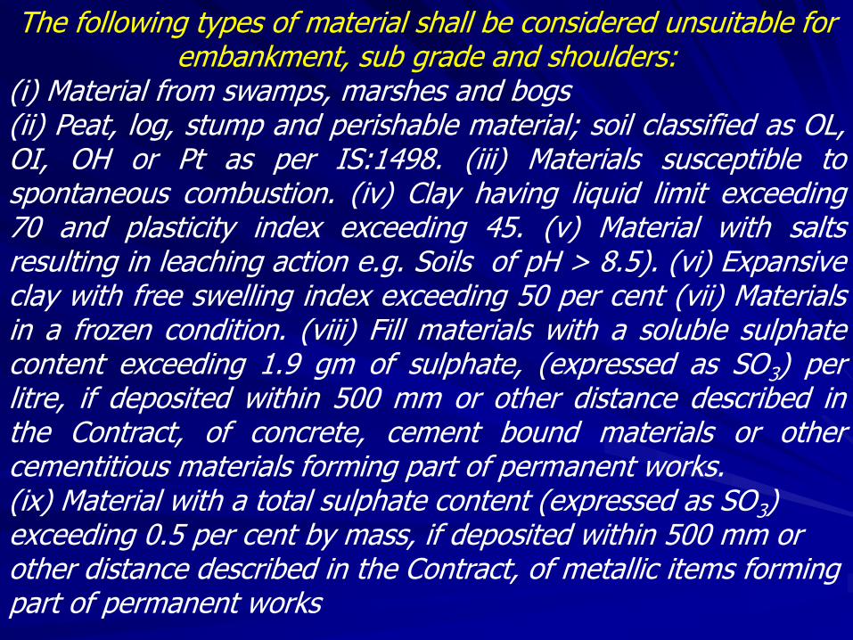
The following types of material shall be considered unsuitable for embankment, sub grade and shoulders:
(i) Material from swamps, marshes and bogs (ii) Peat, log, stump and perishable material; soil classified as OL, OI, OH or Pt as per IS:1498. (iii) Materials susceptible to spontaneous combustion. (iv) Clay having liquid limit exceeding 70 and plasticity index exceeding 45. (v) Material with salts resulting in leaching action e.g. Soils of pH > 8.5). (vi) Expansive clay with free swelling index exceeding 50 per cent (vii) Materials in a frozen condition. (viii) Fill materials with a soluble sulphate content exceeding 1.9 gm of sulphate, (expressed as SO3) per litre, if deposited within 500 mm or other distance described in the Contract, of concrete, cement bound materials or other cementitious materials forming part of permanent works. (ix) Material with a total sulphate content (expressed as SO3) exceeding 0.5 per cent by mass, if deposited within 500 mm or other distance described in the Contract, of metallic items forming part of permanent works

MORD 301 Embankment Requirements
Liquid limit < 70%, Plasticity Index< 45%,FSI < 50%
MDD(min):1.44 g/cc up to 3m height and 1.52vg/cc for embankment > 3m height.
In case of fly Ash minimum MDD is reduced to
0.9 g/cc as per IRC Special Publication No.58
Breaking clods: 75mm maximum
Moisture content: +1% or -2% of OMC for sandy / silty soils and OMC to OMC + 2% for clayey / BC soils
Maximum layer thickness: 200mm (vibratory roller)
or 150mm in case of smooth wheeled roller
Trimming: additional width of 0.6m on either side
Relative compaction: 97%

MORD 303 Sub Grade Requirements
Existing sub grade:
If sub grade CBR is less than 2%, a capping layer of 100mm thick with 10% CBR soil is to be provided and a CBR of 2% is to be taken for crust design
New sub grade and Shoulders:
MDD (min) is 1.65 g/cc
Moisture content: +1% or -2% of OMC
Relative Compaction: 100%
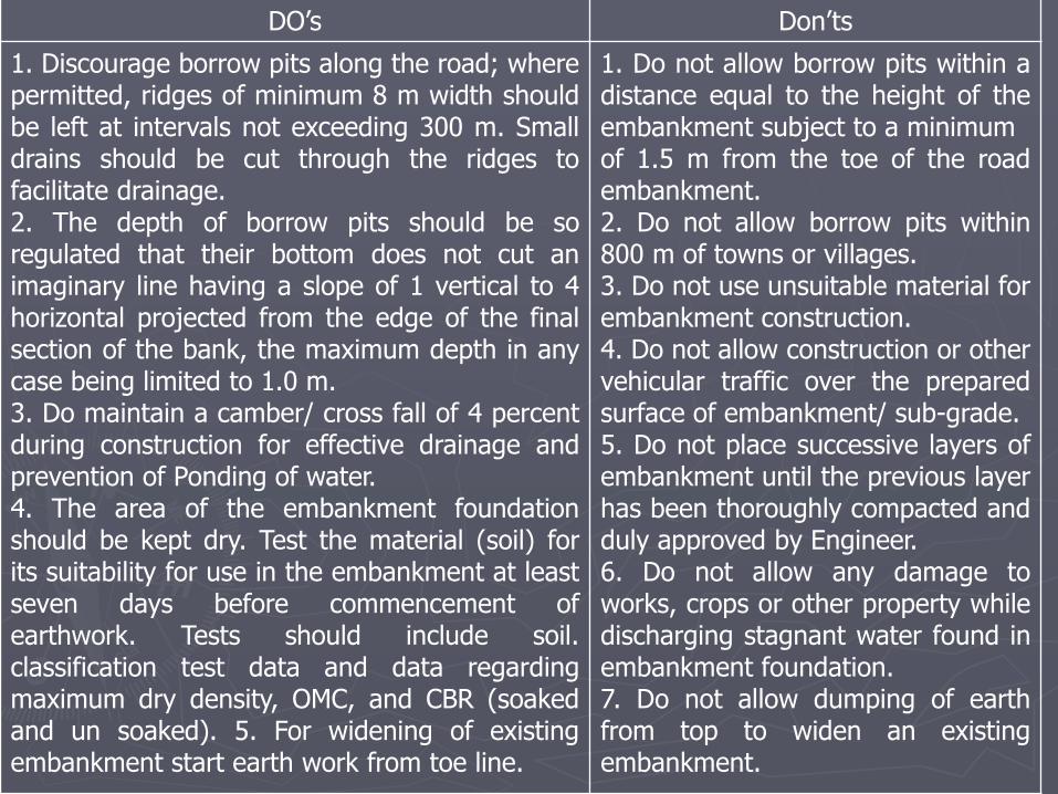
DO’s Don’ts
1. Discourage borrow pits along the road; where permitted, ridges of minimum 8 m width should be left at intervals not exceeding 300 m. Small drains should be cut through the ridges to facilitate drainage. 2. The depth of borrow pits should be so regulated that their bottom does not cut an imaginary line having a slope of 1 vertical to 4 horizontal projected from the edge of the final section of the bank, the maximum depth in any case being limited to 1.0 m. 3. Do maintain a camber/ cross fall of 4 percent during construction for effective drainage and prevention of Ponding of water. 4. The area of the embankment foundation should be kept dry. Test the material (soil) for its suitability for use in the embankment at least seven days before commencement of earthwork. Tests should include soil. classification test data and data regarding maximum dry density, OMC, and CBR (soaked and un soaked). 5. For widening of existing embankment start earth work from toe line.
1. Do not allow borrow pits within a distance equal to the height of the embankment subject to a minimum of 1.5 m from the toe of the road embankment. 2. Do not allow borrow pits within 800 m of towns or villages. 3. Do not use unsuitable material for embankment construction. 4. Do not allow construction or other vehicular traffic over the prepared surface of embankment/ sub-grade. 5. Do not place successive layers of embankment until the previous layer has been thoroughly compacted and duly approved by Engineer. 6. Do not allow any damage to works, crops or other property while discharging stagnant water found in embankment foundation. 7. Do not allow dumping of earth from top to widen an existing embankment.

Appropriate Technology and machinary For Earthwork and Subgrade Construction
1. For clearing, grubbing and excavation : Rippers towed
by agricultural tractor 2. For hauling of earth : Agricultural tractor-trailer 3. For spreading of soil in layers : Spreading blades
attached to agricultural tractor 4. For adding water : Water Bowser towed by
agricultural tractor 5. For mixing of soil with water : Agricultural tractor-
towed disc harrows 6. For compaction in earthwork and : 80-100 kN static
smoothsubgrade construction wheeled road roller for compacted thickness of 100 mm.

Loading of embankment material at borrow source

Dumping of embankment material

Preparation of embankment

Rapid Determination of Moisture Content from Gas Pressure
developed by the Reaction of Calcium Carbide with the Free
Water of the Soil

Loose earth shall not be allowed to soak.

watering of embankment material

Field density test for embankment layers

Dumping of sub grade material

1.68
1.7
1.72
1.74
1.76
1.78
1.8
1.82
1.84
1.86
0 5 10 15 20
Se…
Moisture
Content %
Dry Density
g/cc
3.12 1.74
4.3 1.77
5.41 1.79
7.3 1.85
12.85 1.757
15.71 1.69
Moisture content versus Dry density relationship for a
soil of poorly graded sands with little or no fines SP
OMC = 7.3 %
MDD = 1.85 g/cc

grading of sub grade material
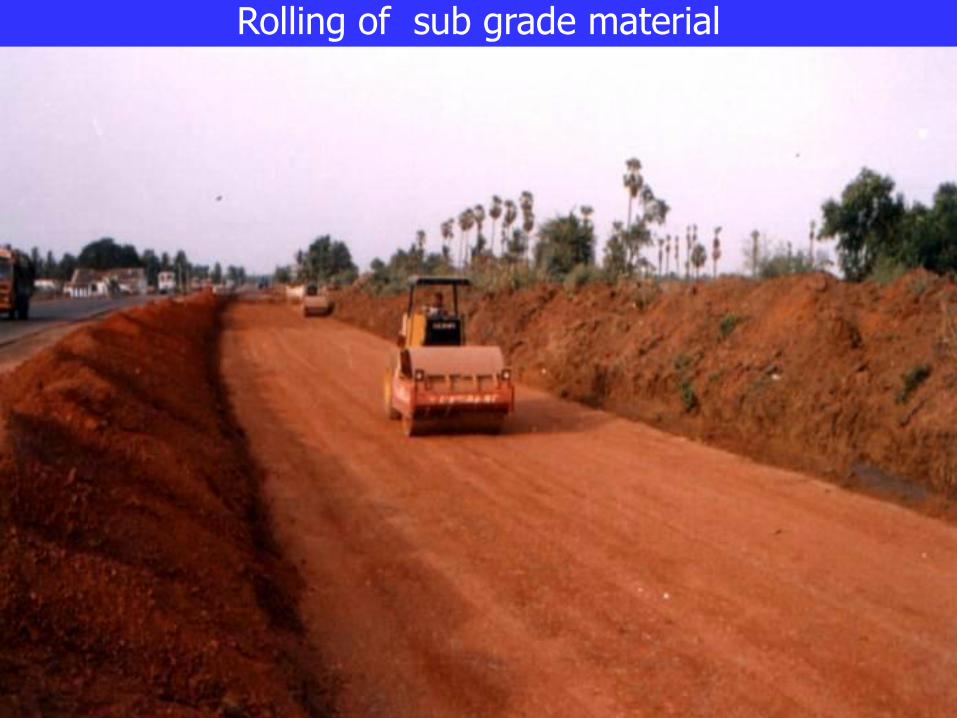
Rolling of sub grade material

Field density testing of sub grade material

Fly ash for road embankment
Ideally suited as backfill material for urban/ industrial areas and areas with weak sub soils
Higher shear strength leads to greater stability
Design is similar to earth embankments
Intermediate soil layers for ease of construction and to provide confinement
Side slope erosion needs to be controlled by providing soil cover
Can be compacted under inclement weather conditions
15 to 20 per cent savings in construction cost depending on lead distance

Fly ash for road embankment
Earth Cover
Earth
Cover
Bottom ash or Pond ash
Typical cross section of fly ash road embankment

Approach embankment for second Nizamuddin bridge at Delhi
Length of embankment - 1.8 km
Height varies from 6 to 9 m
Ash utilised - 1,50,000 cubic metre
Embankment opened to traffic in 1998
Instrumentation installed in the
embankment showed very good
performance
Approximate savings due to usage of fly
ash is about Rs.1.00 Crore

Approach embankment for second Nizamuddin bridge at Delhi

MORD Specification 401
Granular Sub Base
Minimum CBR = 20% (on economical basis,15% may be permitted by competent authority)
Material in mix passing 425 micron sieve shall have Liquid limit less than 25% Plasticity index less than 6% Material passing 75 micron sieve shall be less than 10%.
(less than 5% on clayey sub grades) Material in the mix shall satisfy specified grading Wet Aggregate Impact value shall be less than 50% Layer thickness: 100 mm compacted with smooth wheeled roller 225 mm compacted with vibratory roller Moisture content: + 2% to – 2% of OMC Relative compaction: 100% ( Standard Procter’s test)

IS Sieve
Designation
Percent by weight passing through the IS sieve
Grading I Grading II Grading III
75.0 mm 100 -- --
53.0 mm 100
26.5 mm 55-75 50-80 100
4.75 mm 10-30 15-35 25-45
0.075 mm < 10 < 10 < 10
Table 400-1, MORD Specifications for Rural Roads Grading for Granular Sub-Base materials
1) Liquid limitt < 25% and plasticity index < 6% 2) On clayey sub grade % passing on 75 micron sieve shall not
exceed 5% 3) Wet Aggregate Impact Value shall not exceed 50%

Methodology 1. Obtain materials from approved sources. The material should be natural sand, moorum, gravel,crushed stone, crushed slag, brick metal, kankar or a combination thereof and it shall conform to grading and physical requirements indicated in Table 401.1 2. The sub-base material should be spread in layers not exceeding 100 mm compacted thickness. If suitable vibratory rollers are available, the compacted thickness of layer can be upto a maximum of 225 mm. 3.When the sub-base material consists of a combination of materials, mixing shall be done mechanically by the mix-in-place method, except for small sized jobs. 4. Each layer shall be uniformly spread and thoroughly compacted. Spreading and compaction shall be carried out as per Clause 401.4.2 of the MORD Specifications. 5. Approval of the Engineer should be obtained for each layer. Such an approval would require surface level and compaction control tests. 6. The earthen shoulders should be constructed simultaneously with the sub-base construction.

DO’s Don’ts
1. Ensure uniform mixing of GSB
material and water by
mechanical means like tractor
towed implements.
2. Ensure that on clayey sub
grades, the percent fines passing
75 micron in the GSB material do
not exceed 5 percent.
3. Do provide aggregate plugs at
the exposed edges of GSB where
extended over the full formation
width.
4. Look for soft patches, if any,
and rectify them by removing or
adding fresh material and
compacting the same thoroughly.
1. Do not permit organic or
other deleterious materials.
2. Do not use materials,
which do not conform to the
specified requirements, shall
not be used.
3. Do not allow rejected
material to remain at site to
prevent its reuse. The
rejected material shall be
marked with lime.

Preparation of Granular Sub base mix using 45% gravelly soil, 35% sand and 20% grade III metal

Construction of Granular Sub base mix using 45% gravelly soil, 35% sand and 20% grade III metal
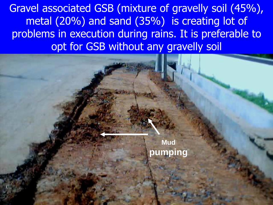
Gravel associated GSB (mixture of gravelly soil (45%), metal (20%) and sand (35%) is creating lot of
problems in execution during rains. It is preferable to opt for GSB without any gravelly soil
Mud
pumping

Definition of sand and gravel as per Code IS: 1490 – 1987
Sand and gravel are defined as Cohesion less
aggregates of angular, sub-angular, sub-
rounded, rounded, flaky or flat fragments of
more or less unaltered rocks or minerals.
According to the system,
gravel is the fraction of the material between
80mm IS sieve size and 4.75mm IS sieve size.
Sand is a fraction of the material between
4.75mm IS sieve size and 75 micron IS sieve
size.

River gravel along Wankidi vaagu across which is being constructed in
km 17/10 of Wankidi Kagaznagar in Adilabad District. This type of
material satisfies gravel requirements as per IS code or MORT&H
specifications. AIV = 14%. It satisfies grading III of table 400 – 2 for Granular Sub Base
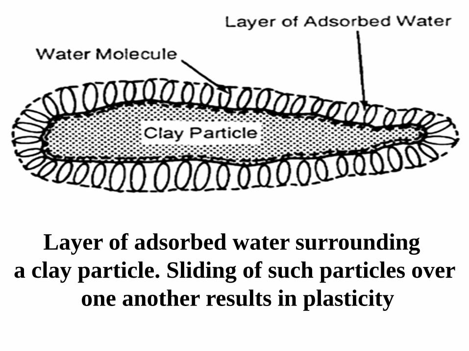
Layer of adsorbed water surrounding
a clay particle. Sliding of such particles over
one another results in plasticity

Natural gravelly soil
LL = 38%, PI = 18%
Position after 24 hours
of adding water
Total Absorption of particles indicate the presence of
negative charged particles in the gravelly soil. It indicates
high PI and LL values. It proves that the above sample is
earthen material only but not gravel or moorum.
Use of such soil presuming it as gravel is causing damage
and poor condition of Village Roads, Major District Roads,
State Highways and National Highways. Highway Engineers
must be able to differentiate between earth and gravel

GSB using crushed quarry spoils and granite for Pushkaram
work in Narsapur in WG Dt. Similar mix is being used as GSB
in NHAI works. This type of mix eliminates all problems
associated with gravel combinations

Another view of GSB without gravel in Narsapur
Drainage: Excellent, CBR: more than 60%

GSB with gravelly soil (45%), stone dust (35%) and metal
(20%) also caused problems when executed during rainy
season

GSB using gravel with some stone content being done in
4-laning of NH5 in Srikakulam District. Here, it contains lot of
fines with high Plasticity Index value. It may give the required
CBR but fails in plasticity

GSB with HBG materials as per Grading III of MORD table
400-1. Stone dust and 6mm to 10mm chips are mixed to
satisfy the grading. It is producing CBR of more than 30%
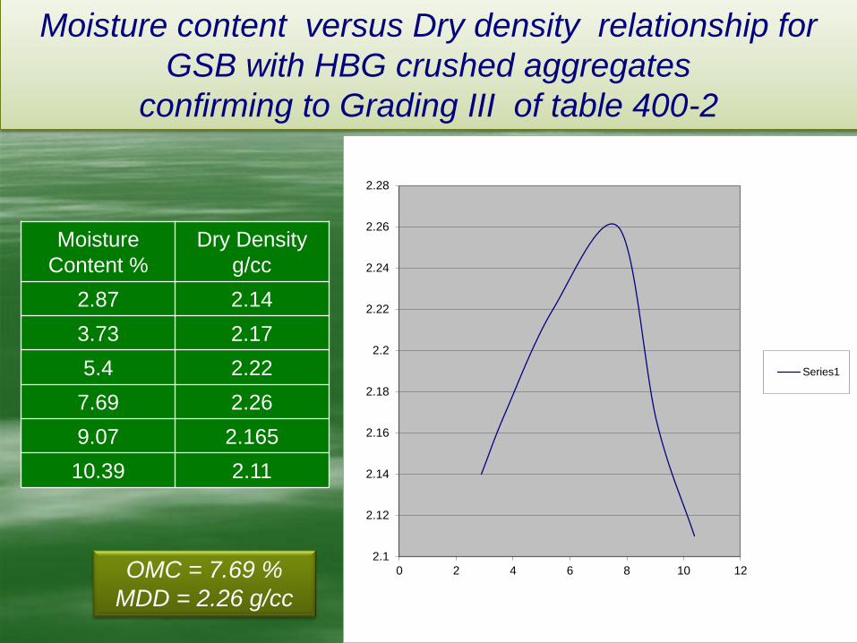
Moisture
Content %
Dry Density
g/cc
2.87 2.14
3.73 2.17
5.4 2.22
7.69 2.26
9.07 2.165
10.39 2.11
Moisture content versus Dry density relationship for
GSB with HBG crushed aggregates
confirming to Grading III of table 400-2
OMC = 7.69 %
MDD = 2.26 g/cc
2.1
2.12
2.14
2.16
2.18
2.2
2.22
2.24
2.26
2.28
0 2 4 6 8 10 12
Series1

GSB using HBG materials as per grading III of MORD table
400-1. Stone dust, 6mm chips and 10 mm chips are used. It is
good for drainage and produce CBR above 30%

GSB using HBG materials as per MORD grading III of table
400-1. Stone dust, 6mm chips and 10 mm chips are used. It is
good for drainage and produce CBR above 30%. NABARD
work: Narakoduru Anantavarappadu road, Guntur District

GSB using HBG materials as per grading III of MORD table
400-1. Stone dust, 6mm chips and 10 mm chips are used. It is
good for drainage and produce CBR above 30%
Machavaram village limits in Guntur district

GSB with alternate materials
WBM with grade I HOG metal without blindage. This is an
excellent GSB option. It gives very high CBR values(>50%)
and also serves as a good drainage layer

MORD Specifications 402: Gravel/ Soil-Aggregate 403: Lime treated soil for improved sub grade/ sub-base 404: Cement treated soil sub-base/ base 408: Local materials for road construction 409: Lime-Fly ash stabilised soil sub-base 410: Industrial Wastes for Road Construction

MORD 408 Local materials for Road Construction
Table 400–13: Manner of using local aggregates in rural road works
State of occurrence of
material
Manner of using in
pavement crust
Test/ quality
requirements
In block or large discrete
particles such as kankar,
laterite, dhandla etc.
As WBM without
screenings/ binder
after breaking into
sizes
Wet AIV ≤ 50%,
40% and 30% for
sub-base, base
and surfacing
Graded form without
appreciable amount of
soil, such as naturally
occurring soils
as granular layer for
sub-base or base or
surfacing
PI: 4 to 10 for
surfacing, PI< 6
for lower
courses. Soaked
CBR for strength
As discrete particles
mixed with appreciable
amount of soil such as soil
gravel mixtures, quarry
wastes etc
Directly as soil-gravel
mix for sub-base or
base or surfacing
Material well
graded. Other
requirements as
above

Base Requirements as per IRC: SP 20 - 2002
Minimum thickness of base: 150mm
Requirements of Base Courses:
Densely Compacted layers with hard, durable, angular and non-plastic materials capable of resisting heavy loads, resistance to lateral movement and transmission of reduced uniform load distribution to sub base layers

Base Courses:
Wet Mix Macadam
Crusher Run Macadam
Water Bound Macadam
Dry Lean Concrete
Requirements of Base Courses:
Densely Compacted layers with hard, durable,
angular and non-plastic materials capable of resisting
heavy loads, resistance to lateral movement and
transmission of reduced uniform load distribution to
sub base layers

WMM WBM with gravelly soil blindage
WBM with screenings and binder
CRM

Sizes Of Coarse Aggregates As Per Apss Table 1501-A
Normal Size
Wholly passing through sieve of square mesh of
size
Wholly retained an a sieve of square mesh
of size
80 mm 100 mm 63 mm
63 mm 80 mm 50 mm
50 mm 63 mm 40 mm
40 mm 50 mm 25 mm
25 mm 40 mm 20 mm
20 mm 25 mm 12.5 mm
12.5 mm
20 mm 10 mm
10 mm 12.5 mm 6.3 mm
6.3 mm 10 mm 2.36 mm
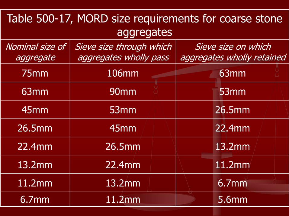
Table 500-17, MORD size requirements for coarse stone aggregates
Nominal size of aggregate
Sieve size through which aggregates wholly pass
Sieve size on which aggregates wholly retained
75mm 106mm 63mm
63mm 90mm 53mm
45mm 53mm 26.5mm
26.5mm 45mm 22.4mm
22.4mm 26.5mm 13.2mm
13.2mm 22.4mm 11.2mm
11.2mm 13.2mm 6.7mm
6.7mm 11.2mm 5.6mm

Test Sub-base Base Surfacing
AIV < 50% < 40% < 30%
FIV < 30% < 25% < 20%
Soundness Test when water absrption > 2%
Loss with sodium sulphate < 12%
Loss with magnesium
sulphate
< 18%
MORD Table 400-7, Physical Requirements of Coarse Aggregates for WBM
For Screenings: LL < 20%, PI < 6% and % passing 75 micron sieve < 10% (405.2.8)
For binder: PI < 6% for sub base and base. PI shall be from 4 to 10% for binder for srfacing (405.2.9)
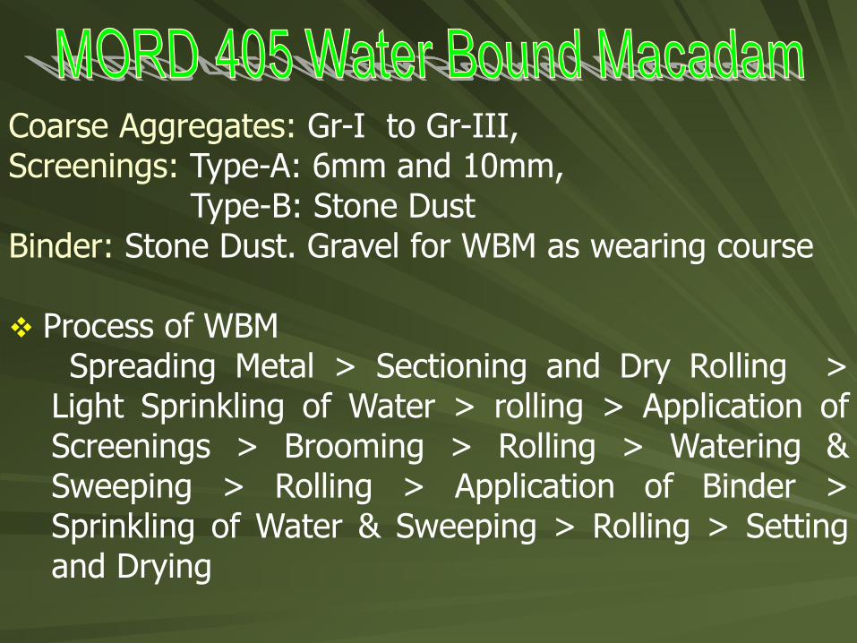
Coarse Aggregates: Gr-I to Gr-III, Screenings: Type-A: 6mm and 10mm, Type-B: Stone Dust Binder: Stone Dust. Gravel for WBM as wearing course Process of WBM
Spreading Metal > Sectioning and Dry Rolling > Light Sprinkling of Water > rolling > Application of Screenings > Brooming > Rolling > Watering & Sweeping > Rolling > Application of Binder > Sprinkling of Water & Sweeping > Rolling > Setting and Drying

DO’s Don’ts
1. Check aggregates for
Soundness test when water absorption is more than 2%
2. Soft aggregate should be
tested for wet aggregate impact
value.
3. Construct shoulders
simultaneously along with
WBM layers.
4. Use inverted choke over fine
grained soil sub-grade.
5. Remove BT surface before
WBM is laid on an existing
black top road.
6. Remove defective macadam to
full depth and replace by fresh
material and re-compact.
1. Do not use any material derived
from rocks e.g. phyllites, shales or
slates.
2. Do not use local soil and clayey
material as screenings or binding
material unless it meats the
requirements of PI mentioned
3. Do not use binding material if
screenings are of crushable type.
4. Do not spread coarse aggregate
more than 3 days in advance of any
subsequent operations.
5. Do not roll if sub-grade is soft or
yielding or causes a wave like motion
while rolling.
6. Do not lay WBM layer on lime
treated sub-base until it has attained
its strength.
7. Do not use screenings to make up
depressions.
8. Do not allow traffic till WBM is fully
set.

IS Sieve Cumulativ
%
passing
specified
125mm 100 100
90mm 92 90 - 100
63mm 45 25 - 60
45mm 8 0 - 15
22.4mm 3 0 - 5
Grade I HBG metal
as per table 400 - 8
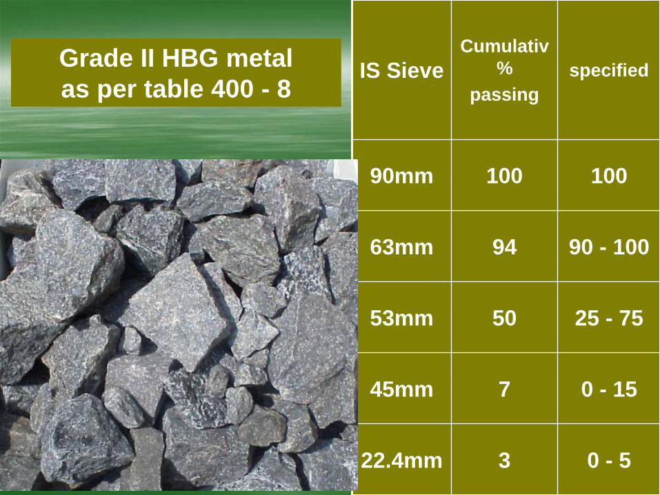
IS Sieve Cumulativ
%
passing
specified
90mm 100 100
63mm 94 90 - 100
53mm 50 25 - 75
45mm 7 0 - 15
22.4mm 3 0 - 5
Grade II HBG metal
as per table 400 - 8

IS Sieve Cumulativ
%
passing
specified
63mm 100 100
53mm 97 95 - 100
45mm 80 65 - 90
22.4mm 8 0 - 10
11.2mm 2 0 - 5
Grade III HBG metal
as per table 400 - 8
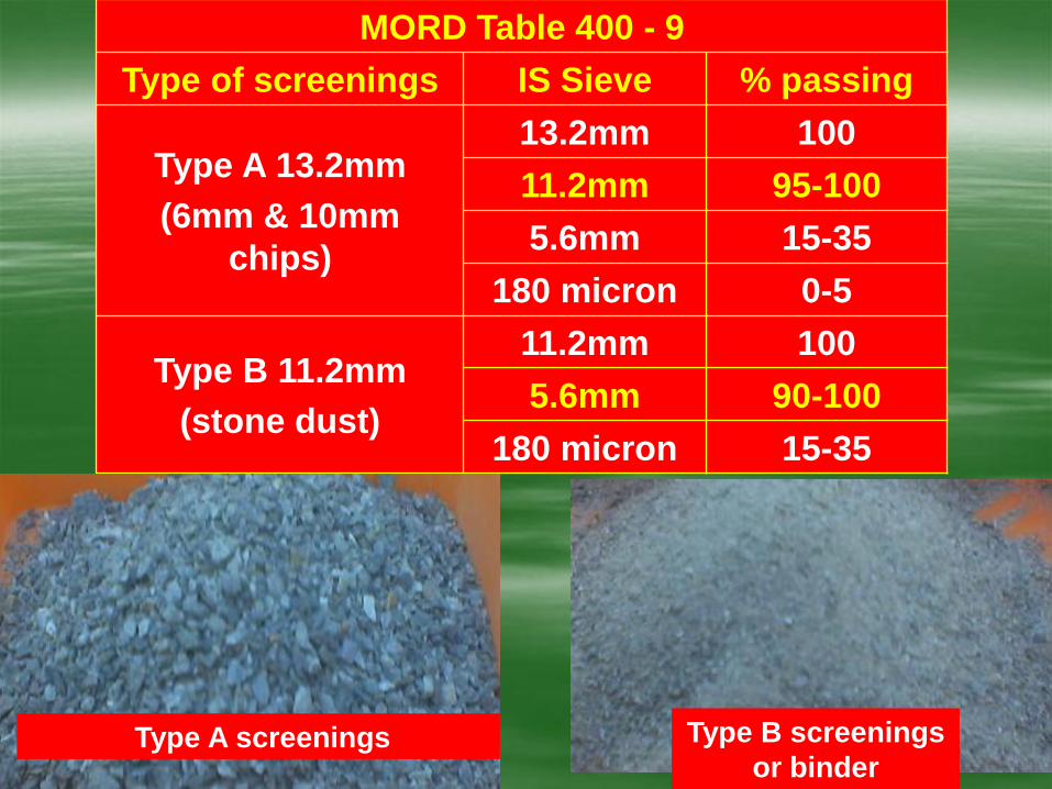
MORD Table 400 - 9
Type of screenings IS Sieve % passing
Type A 13.2mm
(6mm & 10mm
chips)
13.2mm 100
11.2mm 95-100
5.6mm 15-35
180 micron 0-5
Type B 11.2mm
(stone dust)
11.2mm 100
5.6mm 90-100
180 micron 15-35
Type B screenings
or binder Type A screenings

IS
Sieve
Percent passing
Sample 1 Sample 2 Sample 3
Specified passing for
Type B Screenings
11.2mm
100 100 100 100
5.6mm 96.12 98.62 99.54 90 - 100
180 micron
24.52 17.83 20.82 15 - 35
Sieve Analysis of stone dust with type B screenings sieve set

WBM Stone screenings Binder
per 10SqM type quantity/10Sqm
Gr I - 133/100mm type A 0.27 to 0.3 cum 0.08 to 0.10 cum
Gr II – 100/75mm type A 0.12 to 0.15 cum
0.06 to 0.09 cum -do- type B 0.20 to 0.22 cum
Gr III 100/75mm type B 0.18 to 0.21 cum
Item
Coarse
Aggregates
Type A
screenings
(6mm)
Type B
screenings
(dust)
Binder
(dust)
Grad I WBM 1.21 cum 0.27 cum nil 0.08 cum
Grade II WBM with
type A screenings 0.91 cum 0.12 cum nil 0.06 cum
Grade II WBM with
type B screenings 0.91 cum nil 0.20 cum 0.06 cum
Grade III WBM 0.91 cum nil 0.18 cum 0.06 cum

Incorrect practice of WBM with gravelly soil
blindage adopted over the years.


Spreading of metal using templates placed across the road
about 6m apart.

Dry rolled surface
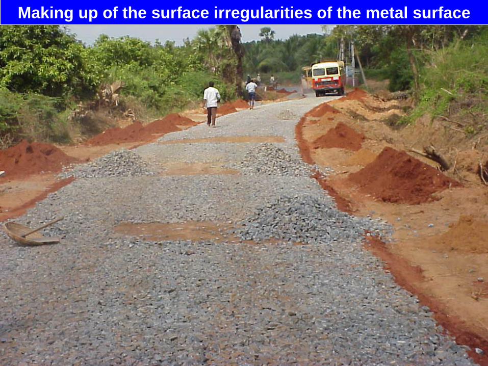
Making up of the surface irregularities of the metal surface

After dry rolling, spreading of screenings is in progress to fill
voids in the coarse aggregates.

Brooming with hand brooms, to fill voids in
the coarse aggregates

Sprinkling of water is in progress
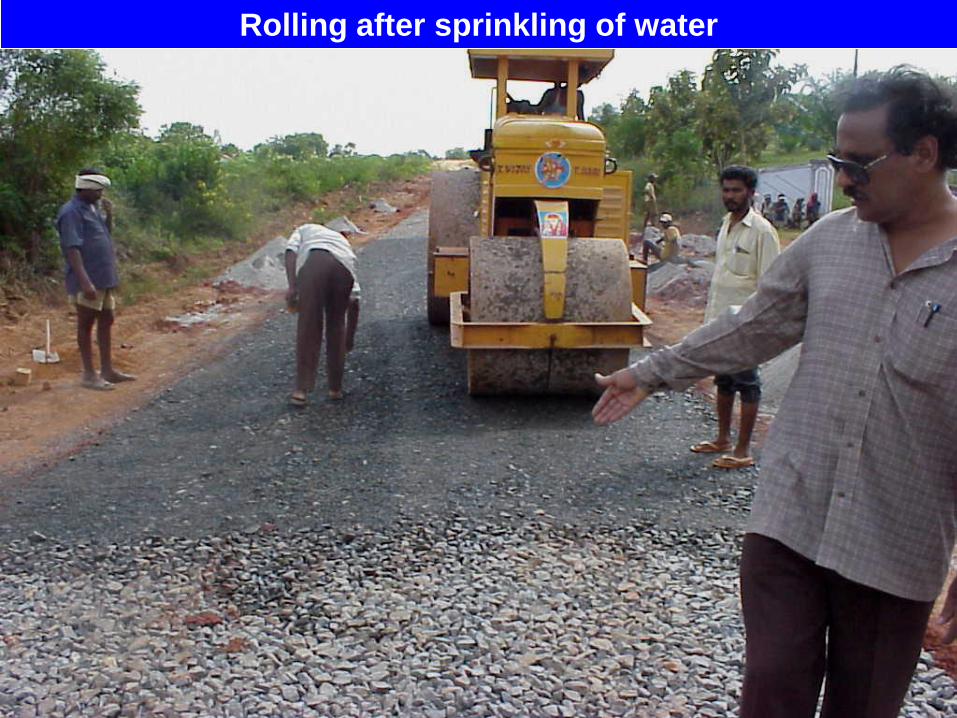
Rolling after sprinkling of water

Application of binding material successively in two or more thin layers. Due to application of stone dust as
screenings and binder internal friction between coarse aggregates is not getting reduced.

GR III WBM with stone screenings as per clause 405 of MORD

WBM using grade III HBG metal and crusher dust as type B
screenings and binder

Surface of WBM with grade II HBG metal. Type A screenings used are
6mm and 10mm and binder is stone dust. Grade III collections in progres.
Narakoduru Anantavarappadu road in Guntur District.

Surface of WBM with grade III HBG metal. Type B screenings and binder
used is stone dust. Narakoduru Anantavarappadu road in Guntur District.
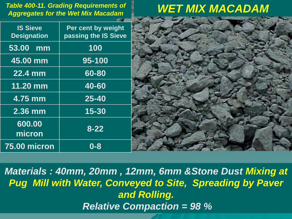
Materials : 40mm, 20mm , 12mm, 6mm &Stone Dust Mixing at
Pug Mill with Water, Conveyed to Site, Spreading by Paver
and Rolling.
Relative Compaction = 98 %
WET MIX MACADAM
IS Sieve
Designation
Per cent by weight
passing the IS Sieve
53.00 mm 100
45.00 mm 95-100
22.4 mm 60-80
11.20 mm 40-60
4.75 mm 25-40
2.36 mm 15-30
600.00
micron 8-22
75.00 micron 0-8
Table 400-11. Grading Requirements of
Aggregates for the Wet Mix Macadam

DO’s Don’ts
1. Ensure compliance of all
material and plant
requirements.
2. Check aggregate for
soundness test when
water absorption is more
than 2 %.
3. Build shoulders
simultaneously along with
WMM layers.
4. Remove BT surface
before WMM is laid on an
existing road.
1. Do not use material
other than crushed
stone.
2. Do not allow
segregation or pockets of
coarse/fine material on
the layer.
3. Do not allow any traffic
on the WMM surface
without covering it with a
wearing course.

Pug mill for Wet Mix Macadam
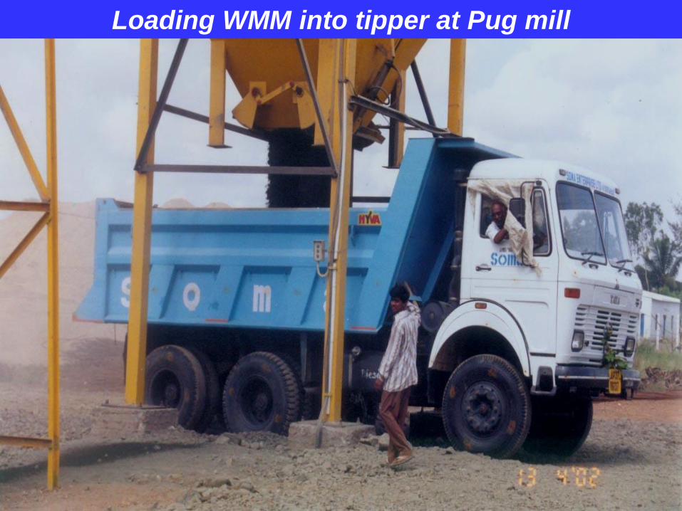
Loading WMM into tipper at Pug mill

Laying of Wet Mix Macadam with paver


Moisture Content %
Dry Density g/cc
4.76 2.11
5.63 2.14
6.08 2.19
6.82 2.32
10.25 2.159
11.86 2.10
Moisture content versus Dry density relationship for
Wet Mix Macadam
OMC = 6.82%
MDD = 2.32 g/cc
2.05
2.1
2.15
2.2
2.25
2.3
2.35
0 5 10 15
Series1

Wet Mix Macadam on Mangalagiri Rayapudi road

BLACK TOPPED SURFACINGS
Strengthening layers
Bituminous Macadam
Modified Penetration Macadam
Wearing Courses
Surface Dressing
Open Graded Premix Carpet
with seal coat
Closely graded premix carpet or Mix
Seal surfacing (hot mix process)

Requirements of BT Surfacing IRC:37, MORD Section 500
o High stability – resisting permanent deformation
o Good durability and long life-resisting traffic abrasion
o Good elastic properties
o Good resistance to fatigue
o Low permeability to water and air
o Good workability when hot
o Good skid resistance
o Good riding quality
o Acceptable level of noise under traffic
o Economical in initial cost and maintenance

MORD 502.Prime Coat over granular base Application of single coat of low viscosity liquid
bituminous material to an absorbent granular surface to any superimposed bituminous treatment
1) It coats and bonds loose mineral particles of granular
surface
2) It water proofs the surface of the base by plugging
capillary or un connected voids
3) It provides adhesion or bond between the granular base
and bituminous layers
MORD Table 500-1, Primer requirements
Porosity Surface Quantity kg/10sqm
Low WBM/WMM 7 - 10
Medium Stabilised base 9 - 12
High Gravel base 12 - 15

Methodology for Prime Coat
1. Bituminous primer should be slow setting bitumen emulsion, use of cutback being restricted to areas having sub zero temperature or for emergency operations. 2. The prime coat should be applied only on the top most granular base layer, over which bituminous treatment is to be applied. The granular base surface should be swept clean of dust and loose particles and where required, lightly and uniformly sprinkled with water to moist the surface. 3. The primer should be sprayed uniformly over the dry surface of absorbent granular base, using suitable bitumen pressure distributor or sprayer capable of spraying primer at specified rates and temperature so as to provide a uniformly unbroken spread of primer. Normal temperature range of spraying emulsion should be 20°C to 60°C. The rate of application depends upon the porosity characteristics of the surface to be primed and is given in above table.

DO’s Don’ts
1. Use slow setting emulsion
and restrict the use of
cutback to subzero
temperature conditions or
emergency operations.
2. Use only pressure
sprayers.
3. Preferably lay a trial
section.
4. The Contractor to
demonstrate at a spraying
trial to ensure that the
equipment is capable of
producing a uniform spray.
1. Do not apply primer
when the atmospheric
temperature in shade is
less than 10°C or when
the weather is foggy, rainy
or windy.
2. Do not allow pouring of
primer using perforated
cans.
3. Do not allow traffic on
primed surface.
4. Do not apply
bituminous material to a
wet surface.

Prime coat over WMM
Check for rate of spread
20cm × 20cm × 3cm trays
for binder collection

On WMM/WBM surface, prime coat followed by sand
flushing is a better option to allow traffic for short duration
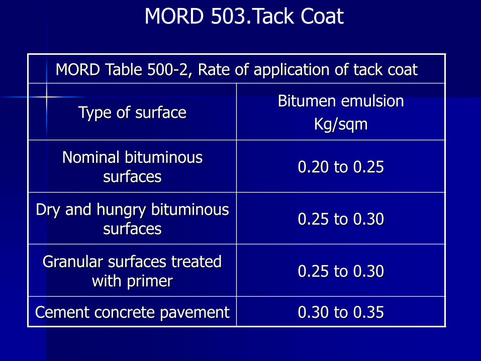
MORD 503.Tack Coat
MORD Table 500-2, Rate of application of tack coat
Type of surface Bitumen emulsion
Kg/sqm
Nominal bituminous surfaces
0.20 to 0.25
Dry and hungry bituminous surfaces
0.25 to 0.30
Granular surfaces treated with primer
0.25 to 0.30
Cement concrete pavement 0.30 to 0.35

Methodology for Tack Coat 1. Use a rapid setting bitumen emulsion for applying a tack coat, the use of cutback being restricted to areas having sub-zero temperature or for emergency applications. 2. The surface on which tack coat is to be applied should be clean, free from dust, dirt and any extraneous materials and dry. 3. The surface should be prepared as per sub-section 501. 4. The binder should be sprayed uniformly over the surface using suitable bitumen pressure sprayer capable of spraying bitumen and emulsion at specified rates and temperature so as to provide a uniformly unbroken spread of bitumen emulsion. For smaller jobs, a pressure hand sprayer may be used. Normal range of spraying temperature should be 20°C-60°C in case of emulsion and 50°C-80°C in case of cutback. The rate of application depends upon the type of surface and is given in above Table . 5. The surface should be allowed to cure until all the volatiles have evaporated.

DO’s Don’ts
1.Plan the work so that no
more than the necessary
tack coat for the day’s
operation is placed on
surface.
2. Handle bituminous
cutback carefully to avoid fire
mishap.
1. Do not apply tack coat
when atmospheric
temperature is less than 10°C or when weather is
foggy, rainy or windy.
2. Do not apply tack coat
on a wet surface.
3. Do not allow any
equipment or vehicles on
Tack Coat.

MORD table 500-5,Manufacturing and Rolling Temperatures
Bitumen
Penetration
Bitumen
Mixing -ºC
Aggregate
Mixing-ºC
Mixed
Material -ºC
Minimum Rolling
temp.
ºC
Laying-ºC
35 (30-40)
160 to 170
160-175 170 Max 110 Min 140 Min
65 (60-70)
150 to 165
150-170 165 Max 100 Min 130 Min
90
(80-100)
140 to 160
140-165 155 Max 100 Min 130 Min

MORD 506 Modified Penetration Macadam (MPM)
Description
Bitumen rate of application for 10sqm area (kg)
75mm 50mm
Bituminous
surface
On WBM
surface
Bituminous
surface
On WBM
surface
Bitumen for grouting 20 20 17.5 17.5
Description
Rate of application for 10sqm area
75mm 50mm
Bituminous
surface,
cum
On WBM
surface,
cum
Bituminous
surface,
cum
On WBM
surface,
cum
40mm size hand
broken metal 0.9 0.6
12mm size chips 0.18 0.18
Tack coat shall be as per clause 503 (table 500 -2)
AIV < 40% and FIV < 25% for coarse aggregates.
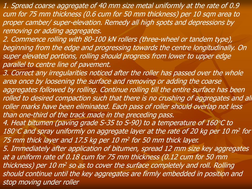
1. Spread coarse aggregate of 40 mm size metal uniformly at the rate of 0.9 cum for 75 mm thickness (0.6 cum for 50 mm thickness) per 10 sqm area to proper camber/ super-elevation. Remedy all high spots and depressions by removing or adding aggregates. 2. Commence rolling with 80-100 kN rollers (three-wheel or tandem type), beginning from the edge and progressing towards the centre longitudinally. On super elevated portions, rolling should progress from lower to upper edge parallel to centre line of pavement. 3. Correct any irregularities noticed after the roller has passed over the whole area once by loosening the surface and removing or adding the coarse aggregates followed by rolling. Continue rolling till the entire surface has been rolled to desired compaction such that there is no crushing of aggregates and all roller marks have been eliminated. Each pass of roller should overlap not less than one-third of the track made in the preceding pass. 4. Heat bitumen (paving grade S-35 to S-90) to a temperature of 160°C to 180°C and spray uniformly on aggregate layer at the rate of 20 kg per 10 m2 for 75 mm thick layer and 17.5 kg per 10 m2 for 50 mm thick layer. 5. Immediately after application of bitumen, spread 12 mm size key aggregates at a uniform rate of 0.18 cum for 75 mm thickness (0.12 cum for 50 mm thickness) per 10 m2 so as to cover the surface completely and roll. Rolling should continue until the key aggregates are firmly embedded in position and stop moving under roller

DO’s Don’ts
1. Ensure that aggregates
conform to grading
specified and are dry and
clean at the time of
laying.
2. Maintain the temperature
of bitumen appropriate to
the grade of bitumen.
3. Remove excessive
deposits of binder during
spray operation.
1. Do not undertake the
work in foggy. rainy or
windy weather or when
the atmospheric
temperature in the shade is less than l0°C.
2. Do not allow any traffic
over Built up spray grout
without laying wearing
course or seal coat.

Modified Penetration Macadam (MPM). 40mm HBG metal at
0.6cum/10 sqm is spread, sectioned and rolled

Modified Penetration Macadam (MPM). 17.5 kg bitumen
grouted and 0.18 cum/10sqm of 12mm key chips applied.
Brooming is in progress.

Finished Modified Penetration Macadam (MPM) 50mm thick
compacted layer.

504 BITUMINOUS MACADAM
MORD Table 500-4, COMPOSITION
IS Sieve (mm) Cumulative % by weight ol aggregate passing
26.5 100
19 90 – 100
13.2 56 – 88
4.75 16 – 36
2.36 4 – 19
0.30 2 -10
0.075 0 -8
Bitumen content, % by weight of mixture
3.30 – 3.50
Bitumen Grade 35 to 90
AIV < 30%, FIV < 25% and WA < 2 %

Methodology for Bituminous Macadam
1. Prepare the base on which bituminous macadam course is to be laid and shape to the specified lines, grade and cross-section. 2. Apply tack coat over the base preparatory to laying of the bituminous macadam. 3. Bituminous Macadam should be prepared in a Hot Mix Plant of adequate capacity. Ensure manufacturing and rolling temperatures for Bituminous Macadam as specified. 4. Transfer the mixed material quickly to site of work and lay by means of an approved self-propelled mechanical paver. 5. Commence initial rolling with 80-100 kN rollers (three-wheel or tandem type), beginning from the edge and progressing towards the centre longitudinally. On super elevated portions, rolling should progress from lower to upper edge parallel to centre line of pavement. Thereafter, do intermediate rolling with vibratory or pneumatic tyred road rollers. This should be followed by final rolling while the material is still workable.
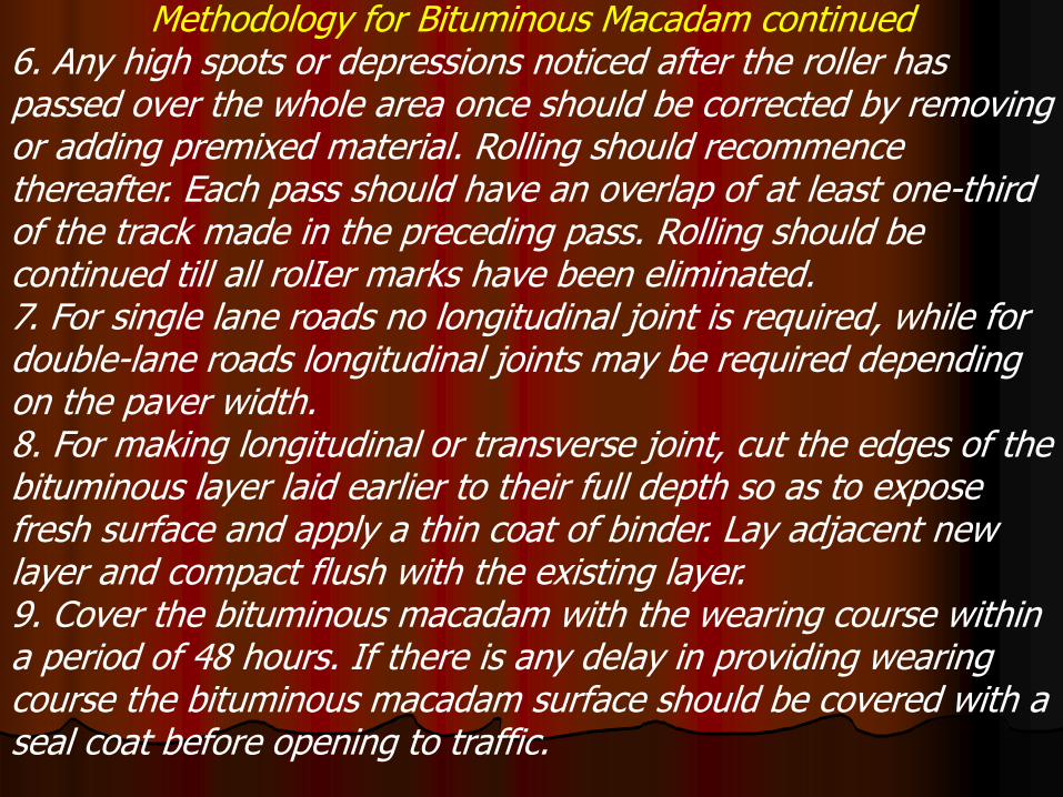
Methodology for Bituminous Macadam continued 6. Any high spots or depressions noticed after the roller has passed over the whole area once should be corrected by removing or adding premixed material. Rolling should recommence thereafter. Each pass should have an overlap of at least one-third of the track made in the preceding pass. Rolling should be continued till all rolIer marks have been eliminated. 7. For single lane roads no longitudinal joint is required, while for double-lane roads longitudinal joints may be required depending on the paver width. 8. For making longitudinal or transverse joint, cut the edges of the bituminous layer laid earlier to their full depth so as to expose fresh surface and apply a thin coat of binder. Lay adjacent new layer and compact flush with the existing layer. 9. Cover the bituminous macadam with the wearing course within a period of 48 hours. If there is any delay in providing wearing course the bituminous macadam surface should be covered with a seal coat before opening to traffic.
DO’s Don’ts
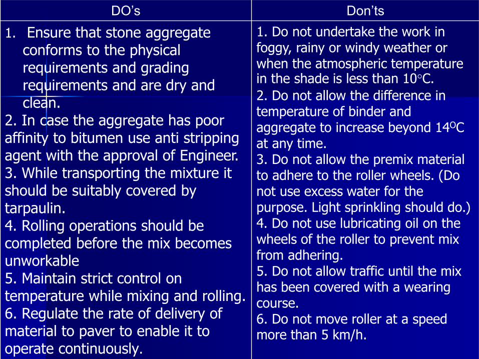
1. Ensure that stone aggregate conforms to the physical requirements and grading requirements and are dry and clean.
2. In case the aggregate has poor affinity to bitumen use anti stripping agent with the approval of Engineer. 3. While transporting the mixture it should be suitably covered by tarpaulin. 4. Rolling operations should be completed before the mix becomes unworkable 5. Maintain strict control on temperature while mixing and rolling. 6. Regulate the rate of delivery of material to paver to enable it to operate continuously.
1. Do not undertake the work in foggy, rainy or windy weather or when the atmospheric temperature in the shade is less than 10°C.
2. Do not allow the difference in temperature of binder and aggregate to increase beyond 14OC at any time. 3. Do not allow the premix material to adhere to the roller wheels. (Do not use excess water for the purpose. Light sprinkling should do.) 4. Do not use lubricating oil on the wheels of the roller to prevent mix from adhering. 5. Do not allow traffic until the mix has been covered with a wearing course. 6. Do not move roller at a speed more than 5 km/h.

MORD 507 Surface Dressing Table 500 – 10: Size requirements of stone chips for
surface dressing
Type of construction Size of chips specification
Single coat surface
dressing or first coat 13.2mm
100% passing 22.4mm sieve
and retained on 11.2mm sieve
Second coat of 2 coat 9.5mm 100% passing 11.2mm sieve
and retained on 5.6mm sieve
Table 500 – 10, Binder rates and chipping quantities
Chipping size Bitumen kg/m2 Emulsion kg/m2 Chips cum/m2
13.2 1.0 1.5 0.010
9.5 0.9 1.4 0.008
6.3 0.75 1.1 0.004
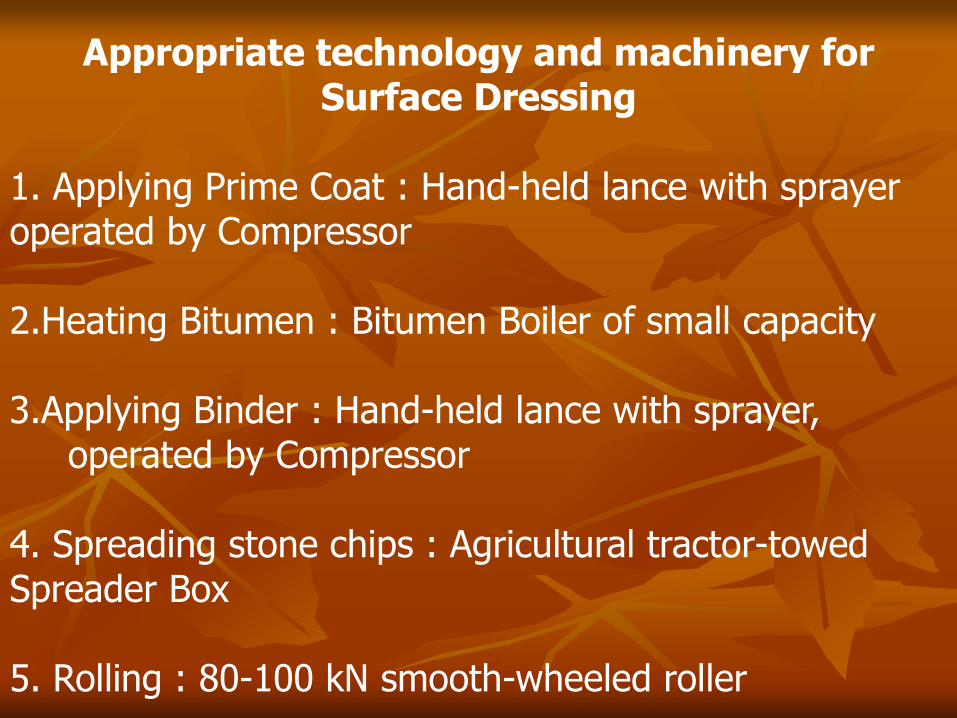
Appropriate technology and machinery for Surface Dressing
1. Applying Prime Coat : Hand-held lance with sprayer operated by Compressor 2.Heating Bitumen : Bitumen Boiler of small capacity 3.Applying Binder : Hand-held lance with sprayer, operated by Compressor 4. Spreading stone chips : Agricultural tractor-towed Spreader Box 5. Rolling : 80-100 kN smooth-wheeled roller
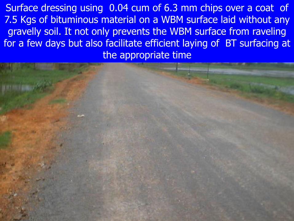
Surface dressing using 0.04 cum of 6.3 mm chips over a coat of 7.5 Kgs of bituminous material on a WBM surface laid without any gravelly soil. It not only prevents the WBM surface from raveling
for a few days but also facilitate efficient laying of BT surfacing at the appropriate time
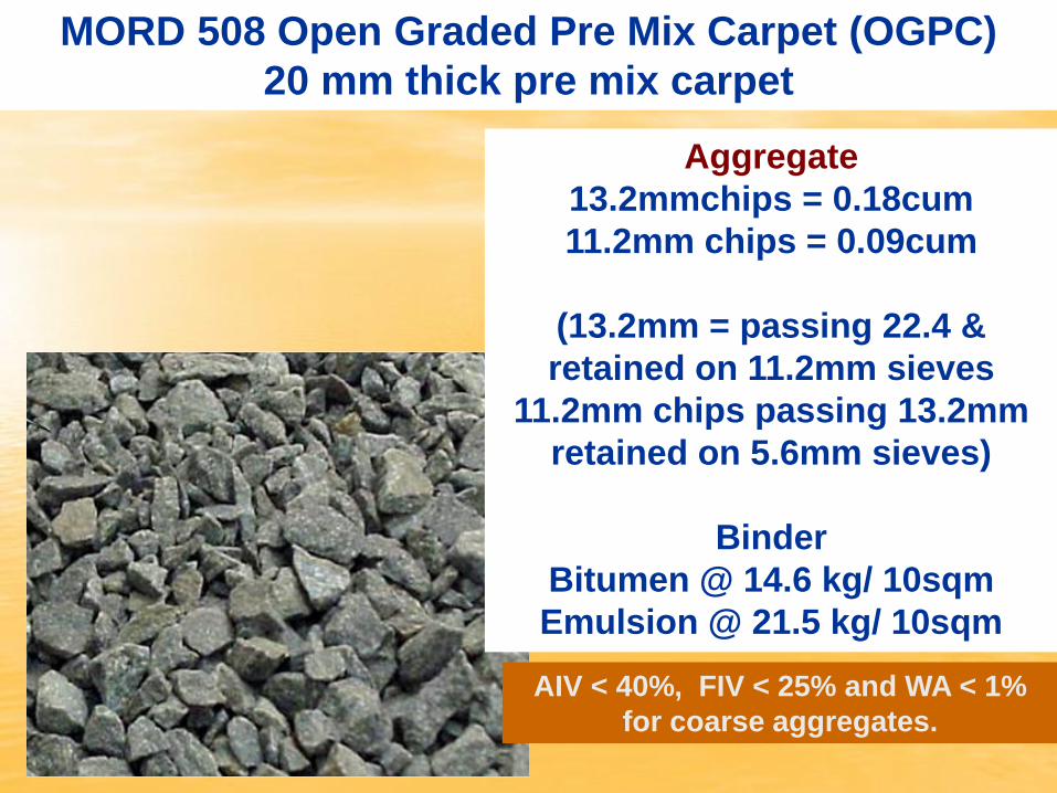
MORD 508 Open Graded Pre Mix Carpet (OGPC)
20 mm thick pre mix carpet
AIV < 40%, FIV < 25% and WA < 1%
for coarse aggregates.
Aggregate
13.2mmchips = 0.18cum
11.2mm chips = 0.09cum
(13.2mm = passing 22.4 &
retained on 11.2mm sieves
11.2mm chips passing 13.2mm
retained on 5.6mm sieves)
Binder
Bitumen @ 14.6 kg/ 10sqm
Emulsion @ 21.5 kg/ 10sqm

Appropriate technology and machinery for Premix Carpet
1.Applying Prime Coat : Hand-held lance provided with sprayer, operated by compressor 2.Applying Tack Coat : Hand-held lance provided with sprayer, operated by compressor 3.Mixing of aggregates and bitumen in : Mini Hot Mix Plant, capacity of with specified quantities around 6 tonnes/hour 4.Transporting from the mixer to site : Tarpaulin- covered tractor-trailer or hand barrows

Methodology for OGPC
1. Mixing should be thorough to ensure that a homogenous mixture is obtained. The temperature of bitumen at the time of mixing should be in the range of 150° C to 163° C and that of aggregates 155°C to 163°C, provided that the difference between the temperature of aggregate and the binder should not exceed 14°C. If modified bitumen is used, temperature should be as recommended in Subsection 512. The temperature at the time of discharge of the mixture should be between l30°C and 160°C.
2. The premixed material shall be spread on the road surface with rakes. 3. Commence rolling with 80-100 kN rollers (three-wheel or tandem type), beginning from the edge and progressing towards the centre longitudinally. (On super elevated portions, rolling should progress from lower to upper edge parallel to centre line of pavement). Continue rolling operations till a smooth uniform surface is achieved and all roller marks are eliminated. Each pass should have an overlap of at least one-third of the track made in the preceding pass. 4. Correct any high spots or depressions noticed after the roller has passed over the whole area once by removing or adding premixed material and re-compacting. 5. Provide a seal coat to the surface immediately after laying the carpet as per details in Sub-section
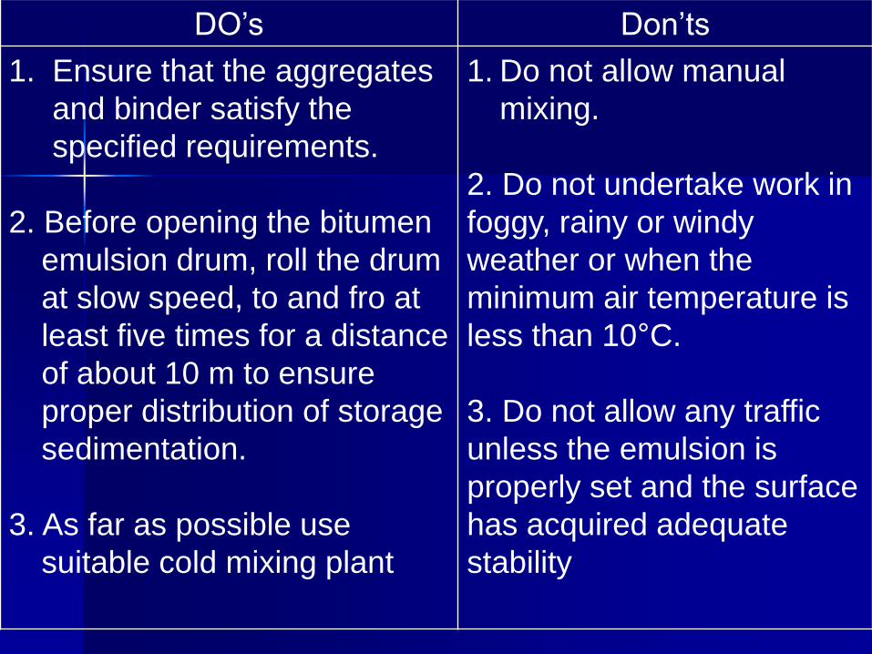
DO’s Don’ts
1. Ensure that the aggregates
and binder satisfy the
specified requirements.
2. Before opening the bitumen
emulsion drum, roll the drum
at slow speed, to and fro at
least five times for a distance
of about 10 m to ensure
proper distribution of storage
sedimentation.
3. As far as possible use
suitable cold mixing plant
1. Do not allow manual
mixing.
2. Do not undertake work in
foggy, rainy or windy
weather or when the
minimum air temperature is
less than 10°C.
3. Do not allow any traffic
unless the emulsion is
properly set and the surface
has acquired adequate
stability

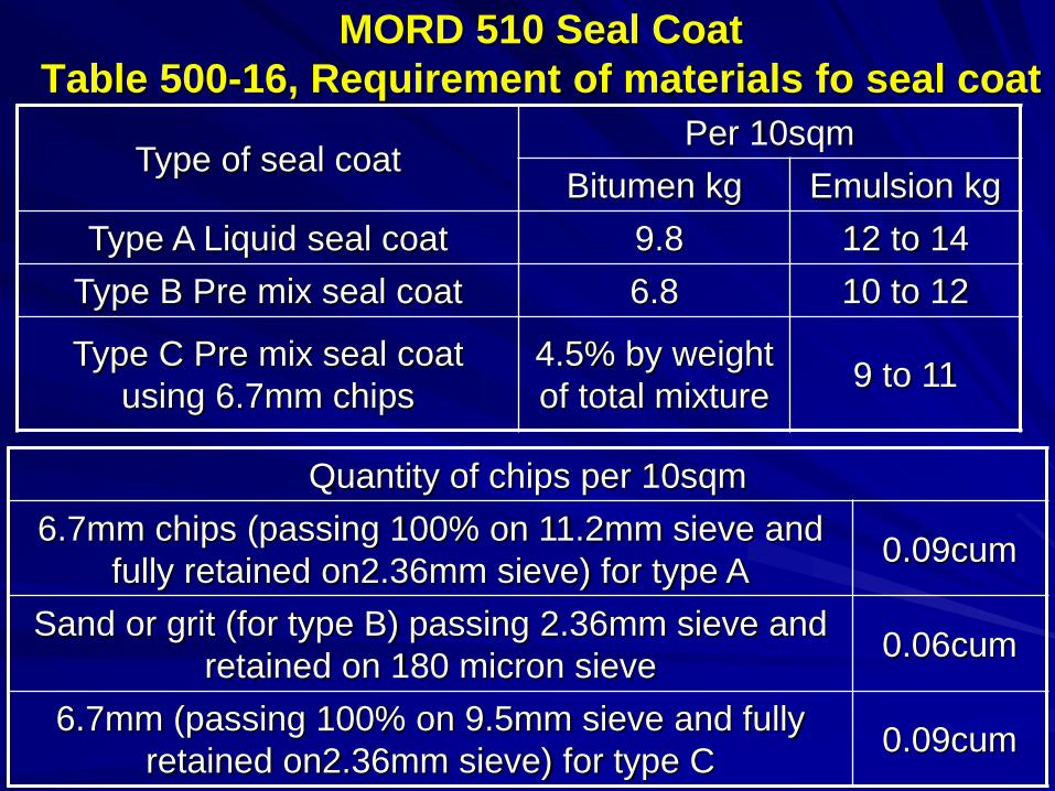
MORD 510 Seal Coat
Table 500-16, Requirement of materials fo seal coat
Type of seal coat Per 10sqm
Bitumen kg Emulsion kg
Type A Liquid seal coat 9.8 12 to 14
Type B Pre mix seal coat 6.8 10 to 12
Type C Pre mix seal coat
using 6.7mm chips
4.5% by weight
of total mixture 9 to 11
Quantity of chips per 10sqm
6.7mm chips (passing 100% on 11.2mm sieve and
fully retained on2.36mm sieve) for type A 0.09cum
Sand or grit (for type B) passing 2.36mm sieve and
retained on 180 micron sieve 0.06cum
6.7mm (passing 100% on 9.5mm sieve and fully
retained on2.36mm sieve) for type C 0.09cum
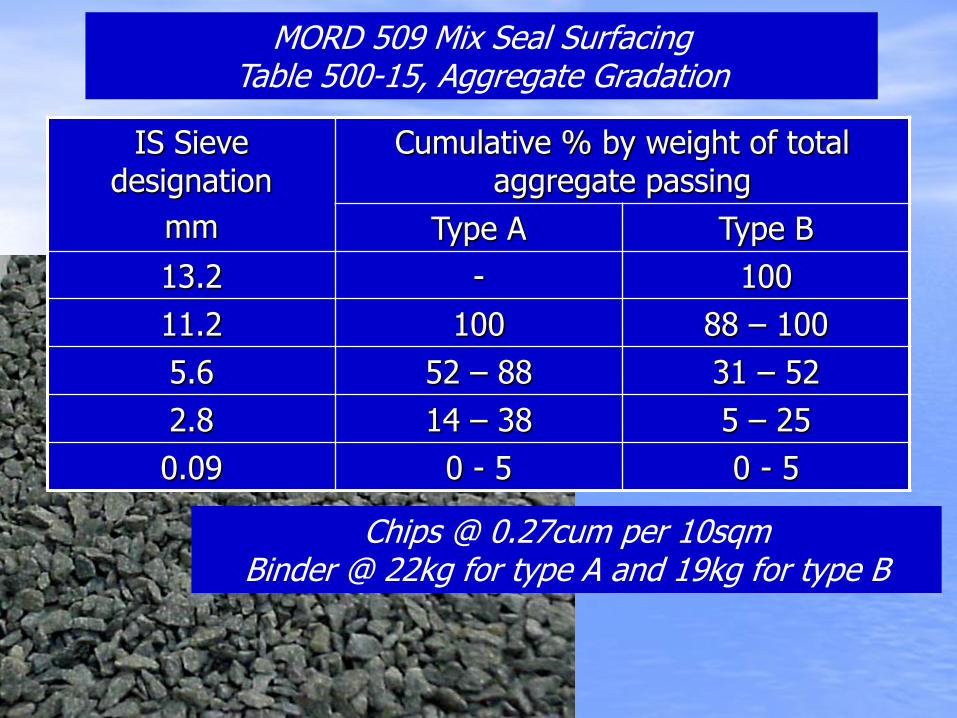
IS Sieve designation
mm
Cumulative % by weight of total aggregate passing
Type A Type B
13.2 - 100
11.2 100 88 – 100
5.6 52 – 88 31 – 52
2.8 14 – 38 5 – 25
0.09 0 - 5 0 - 5
MORD 509 Mix Seal Surfacing Table 500-15, Aggregate Gradation
Chips @ 0.27cum per 10sqm Binder @ 22kg for type A and 19kg for type B
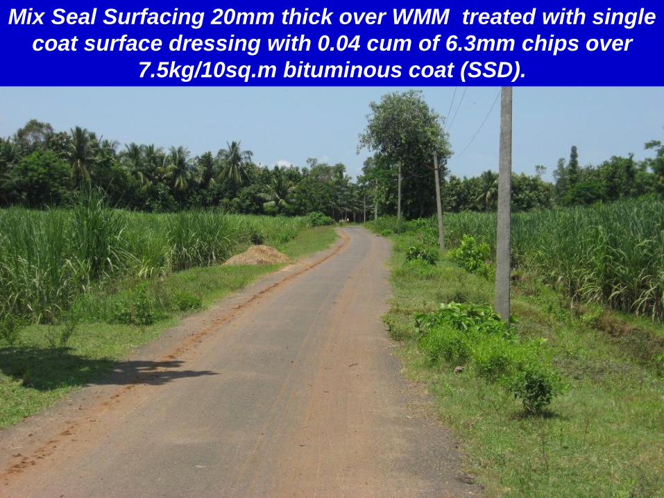
Mix Seal Surfacing 20mm thick over WMM treated with single
coat surface dressing with 0.04 cum of 6.3mm chips over
7.5kg/10sq.m bituminous coat (SSD).

Mix Seal Surfacing 20mm thick over WMM treated with SSD.
SSD is preferred to prime coat as we have to allow traffic.

Revendrapadu Sitanagaram runs along Buckingham canal for
4km and it was in a very bad shape with lot of pot holes and
sunken portions. Number of renewals were done but the road
condition remained the same.

There is lot of WBM crust with gravel blindage. The road was
fully picked up, gravel and BT pieces removed to possible
extent, sectioned, rolled, stone dust blindage done and
rolled.


Condition of Nidubrolu Chandolu road. Soaked and
softened gravel in gravel base and blindage in WBM
is the cause for this condition.

Condition of Nidubrolu Chandolu road after full
picking, removing gravel to possible extent,
sectioning metal, rolling and dust blindage.

Condition of Nidubrolu Chandolu road after doing
single coat surface dressing

Chandolu bridge to Nijampatnam road runs on high
bank of irrigation canal. Doing BT patch work for BT
renewal is very difficult. It is proposed to recycle the
WBM crust.

Condition of Chandolu bridge to Nijampatnam road
after full picking, removing gravel to possible extent,
sectioning metal, rolling and dust blindage.

Chandolu bridge to Nijampatnam road after single
coat surfacing over recycled surface.

Chandolu bridge to Nijampatnam road after
doing BM + SDBC. Shoulder work to be done.

Repalle Tummala Gangadapalem road after picking,
sectioning, stone dust blindage, rolling and single
coat surface dressing

Repalle Tummala Gangadapalem road after
completion BM and SDBC

Gravel collected for berms sticking to the BT wearing coat
and part of the fines of gravel permeate into it. While cleaning
the gravel BT layer is getting peeled off.

Berms done with selected earth on
Rajupalem Bodhanam road

Widening the formation to the required width
WBM over gravel base

Both sides shouders are cut to a depth to get the required
formation width at top. Selected earth with a minimum
density of 1.75g/cc in layers and compacted at OMC.

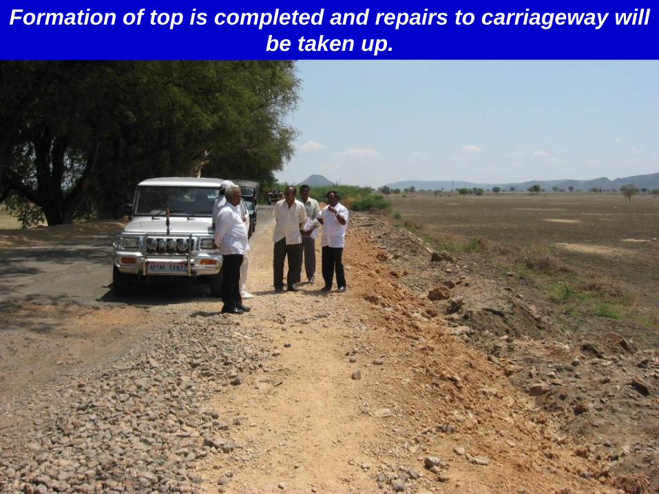
Formation of top is completed and repairs to carriageway will
be taken up.
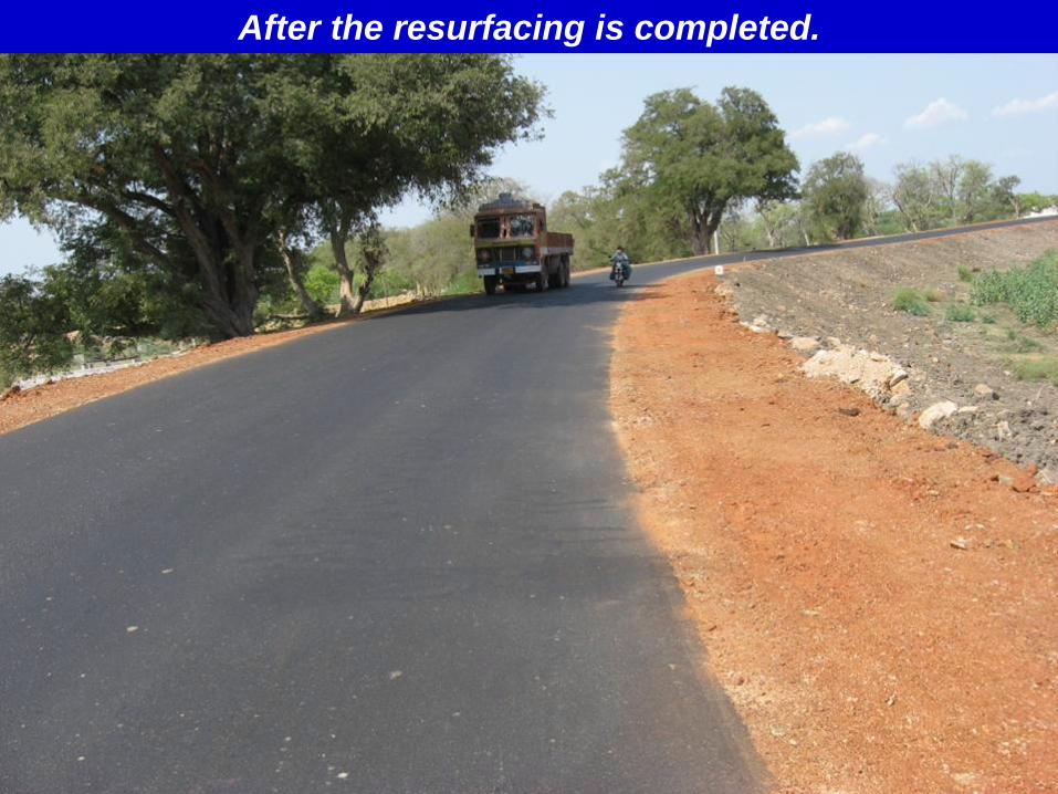
After the resurfacing is completed.