Embed Size (px)
Citation preview
Optical Interconnections,Optical True-Time Delays, andMore... All Based on the White
Cell
Betty Lise AndersonThe Ohio State University
Introduction
What are optical true time delays andwhat are they for?What is an optical interconnection andwhat’s so special about OSU’s?What is a White cell, anyway?
Organization
Motivate true-time delay (TTD) work:phased array antennas» What TTD is» How other people do it
Explanation of the White cellAdapting the White cell to TTDExperimental results
Organization continued
Motivate optical interconnections (as ifthat’s needed)» How other people do it
Adapting the White cell to opticalinterconnectionsSummary and Conclusions
The White cell
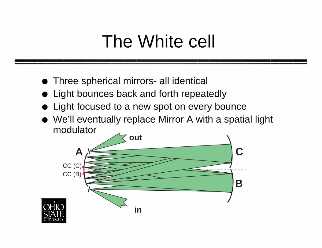
Three spherical mirrors- all identicalLight bounces back and forth repeatedlyLight focused to a new spot on every bounceWe’ll eventually replace Mirror A with a spatial lightmodulator
A
B
C
in
out
CC (B)CC (C)
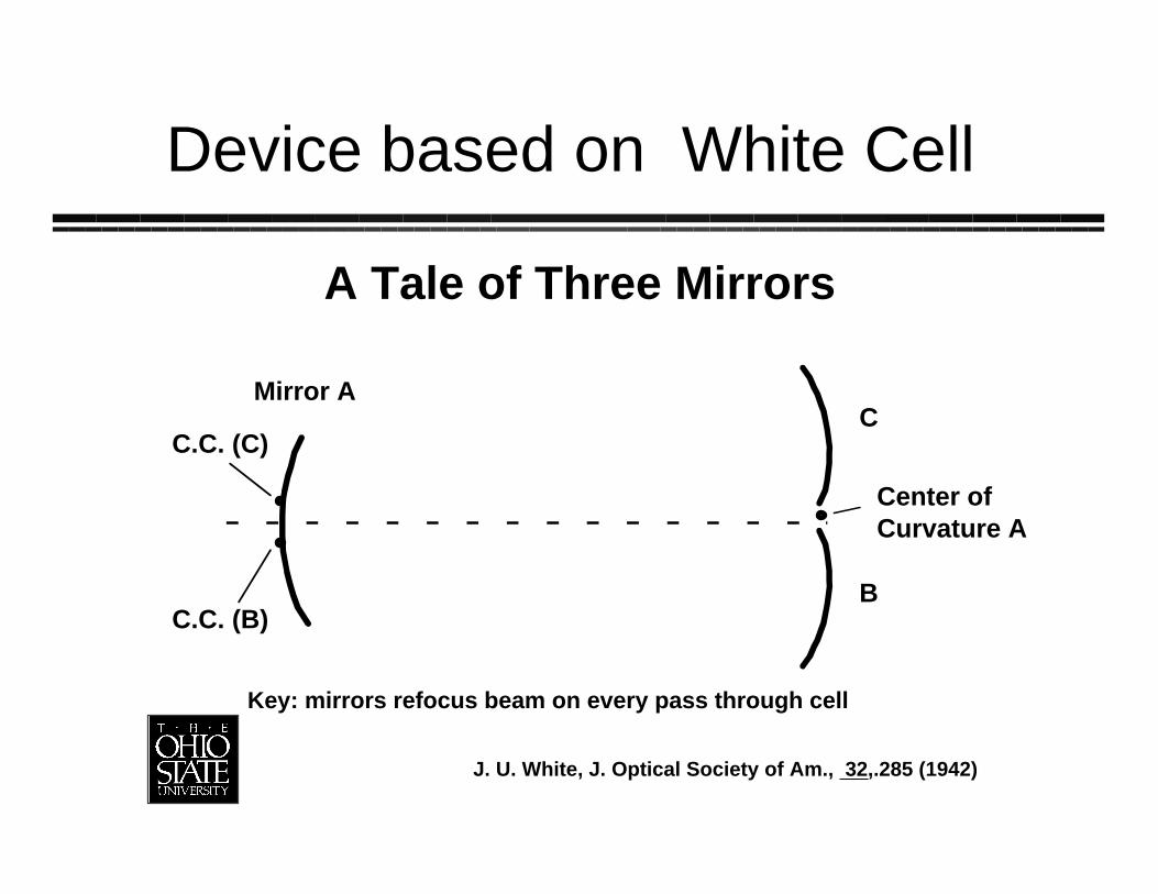
A Tale of Three Mirrors
Mirror AC
B
Center ofCurvature A
C.C. (B)
C.C. (C)
J. U. White, J. Optical Society of Am., 32,.285 (1942)
Key: mirrors refocus beam on every pass through cell
Device based on White Cell
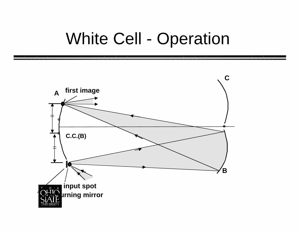
A
C
B
input spot
first image
C.C.(B)
input turning mirror
White Cell - Operation
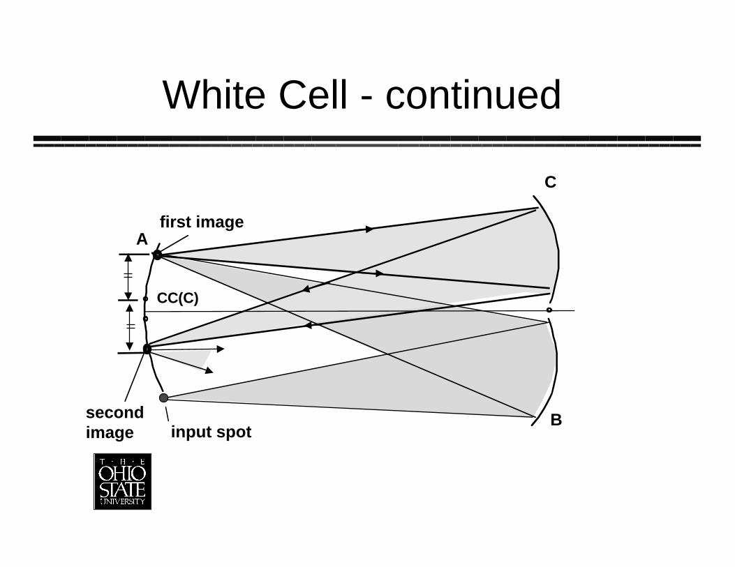
White Cell - continued
B
C
A
secondimage
first image
CC(C)
input spot
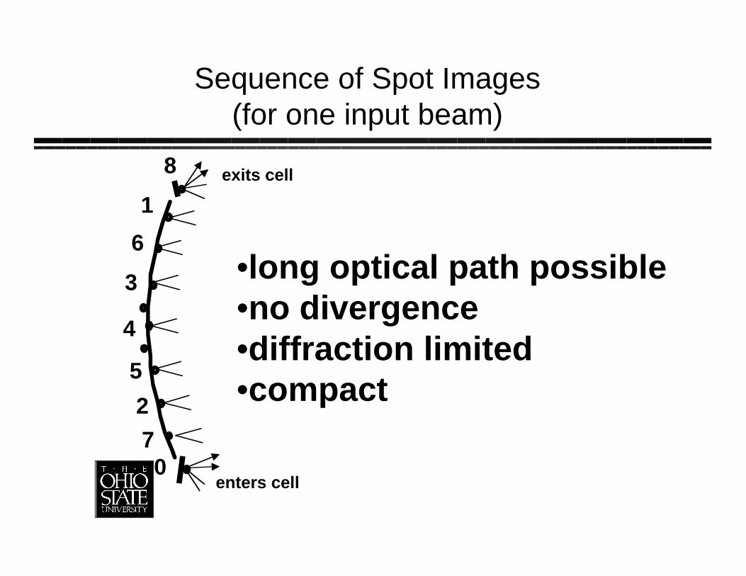
Sequence of Spot Images(for one input beam)
1
2
3
4
5
7
6
8 exits cell
enters cell0
•long optical path possible•no divergence•diffraction limited•compact
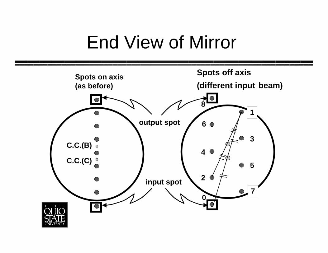
End View of Mirror
Spots on axis(as before)
C.C.(B)
C.C.(C)
0
1
2
3
4
5
6
8
7
Spots off axis
(different input beam)
input spot
output spot
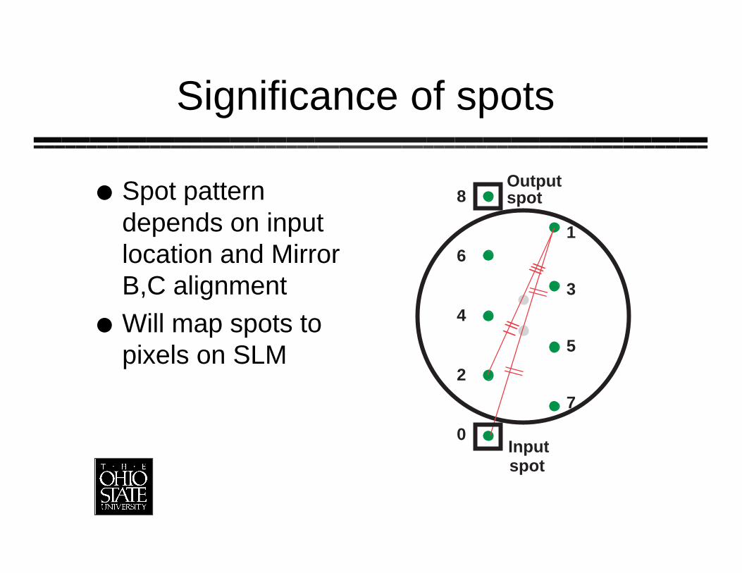
Significance of spots
Spot patterndepends on inputlocation and MirrorB,C alignmentWill map spots topixels on SLM
0
1
2
3
4
5
6
8
7
Outputspot
Inputspot
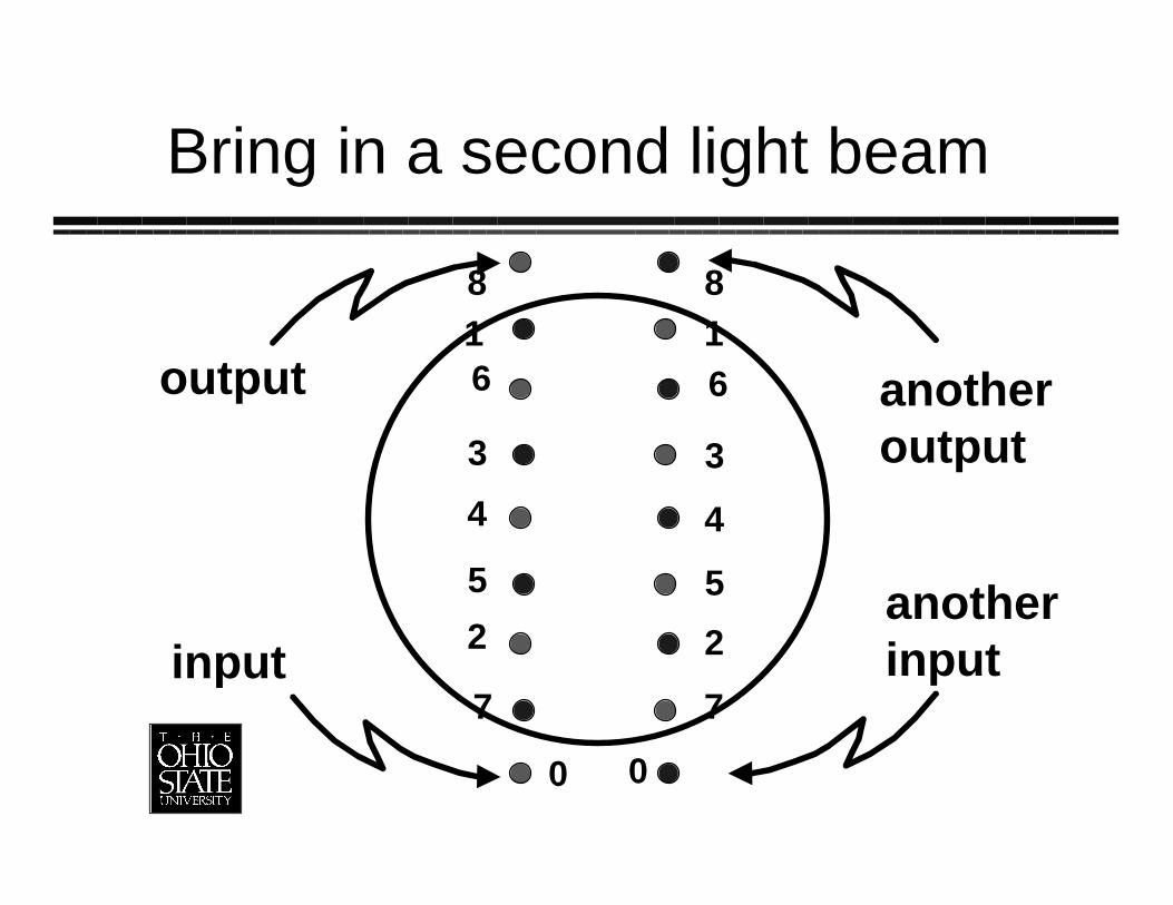
Bring in a second light beam
0
2
3
4
5
6
8
3
5
0
2
4
6
8
input
1 1
77
output
anotherinput
anotheroutput

Complete Spot Set
N input spotsinput turning mirror
N output spots
outputturningmirror
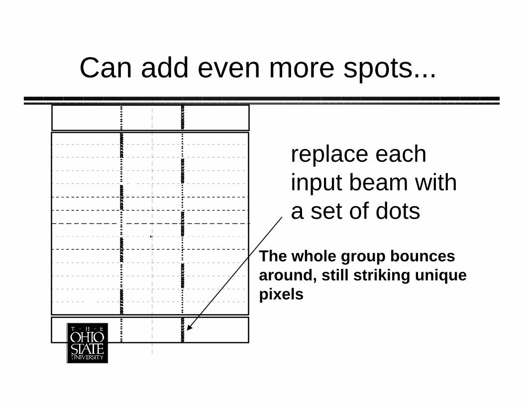
Can add even more spots...
replace eachinput beam witha set of dots
The whole group bouncesaround, still striking uniquepixels
Summary of White cell
beams bounce back and forth a setnumber of times mm determined by alignment of mirrorsmany beams can circulate through cellat same timeNow, on to the problem we want tosolve…
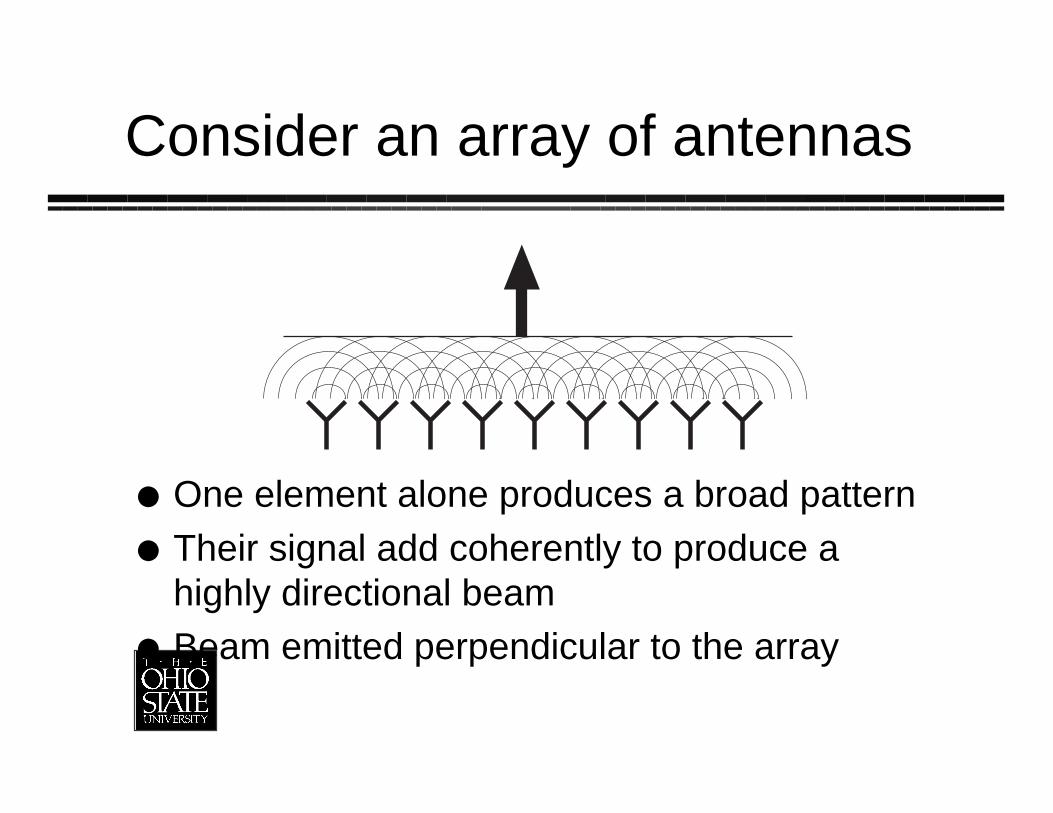
Consider an array of antennas
One element alone produces a broad patternTheir signal add coherently to produce ahighly directional beamBeam emitted perpendicular to the array
To steer the radar beam
Can put the array on a stick and rotate itmechanically» It’s a pain to grease the bearings if the
array is on an airplane or worse a satellite
Use phase shifting to steer the beam
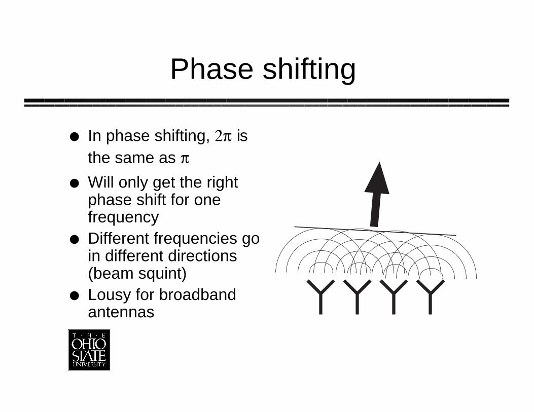
Phase shifting
In phase shifting, 2p isthe same as p
Will only get the rightphase shift for onefrequencyDifferent frequencies goin different directions(beam squint)Lousy for broadbandantennas
True-time delay
A delay of 6p corresponds to someactual timeIf delay all the signals by the right timesinstead of phases, works at allfrequenciesGreat for broadband antennas
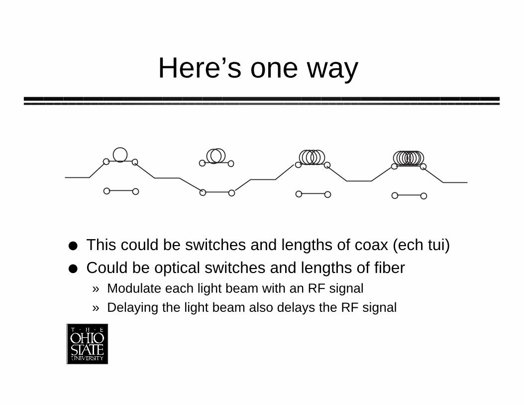
Here’s one way
This could be switches and lengths of coax (ech tui)Could be optical switches and lengths of fiber» Modulate each light beam with an RF signal
» Delaying the light beam also delays the RF signal
There is a snag…
Some delays may be as long as 100’sof nsThat’s meters of coax or striplineHeavy, expensive, and temperaturesensitiveNaturally we want to do this optically…
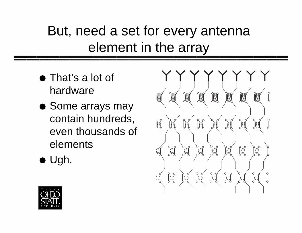
But, need a set for every antennaelement in the array
That’s a lot ofhardwareSome arrays maycontain hundreds,even thousands ofelementsUgh.
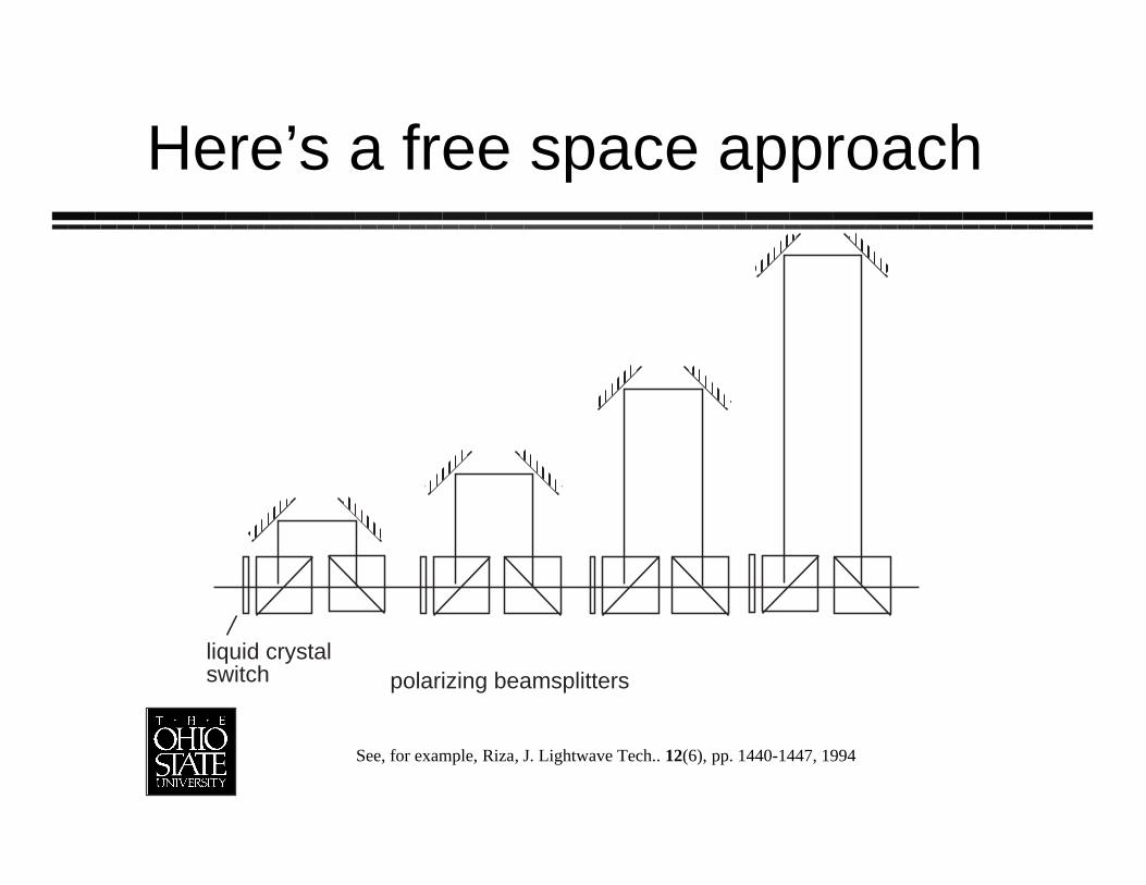
Here’s a free space approach
liquid crystalswitch polarizing beamsplitters
See, for example, Riza, J. Lightwave Tech.. 12(6), pp. 1440-1447, 1994
Features
Free space doesn’t weigh muchEach switch can be a spatial lightmodulator, so can run multiple beams inparallelOur solution also is free space: theWhite cell

The White cell approach
Adapt the White cell to time delaysAlso a free-space approach“Hardware compressive”Avoids divergence problems sincebeams refocused on every bounceanywayWe’ll use liquid crystals and MEMs
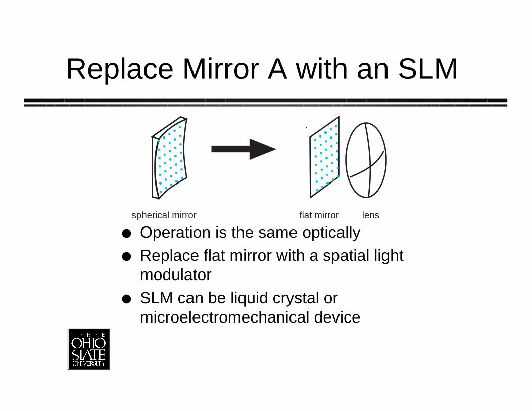
Replace Mirror A with an SLM
Operation is the same opticallyReplace flat mirror with a spatial lightmodulatorSLM can be liquid crystal ormicroelectromechanical device
spherical mirror flat mirror lens
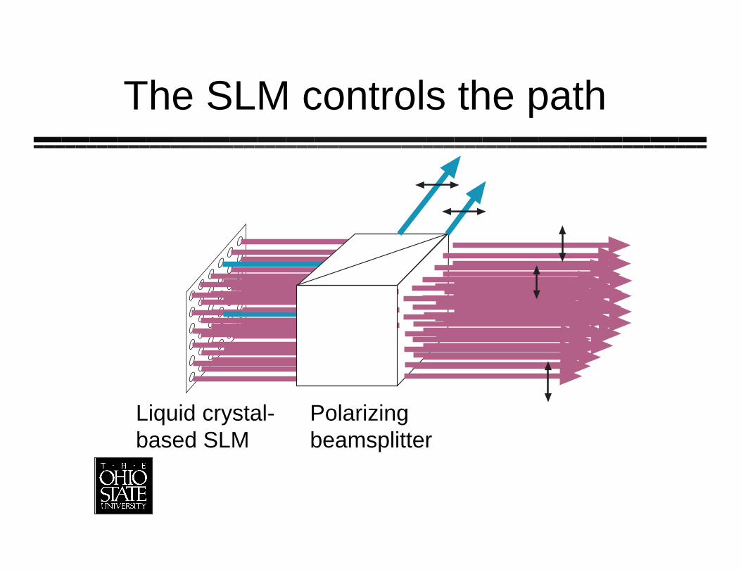
The SLM controls the path
Liquid crystal-based SLM
Polarizingbeamsplitter
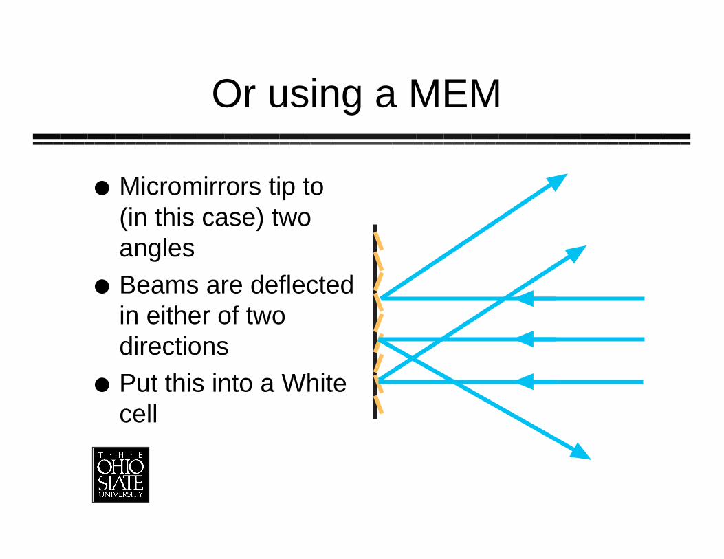
Or using a MEM
Micromirrors tip to(in this case) twoanglesBeams are deflectedin either of twodirectionsPut this into a Whitecell
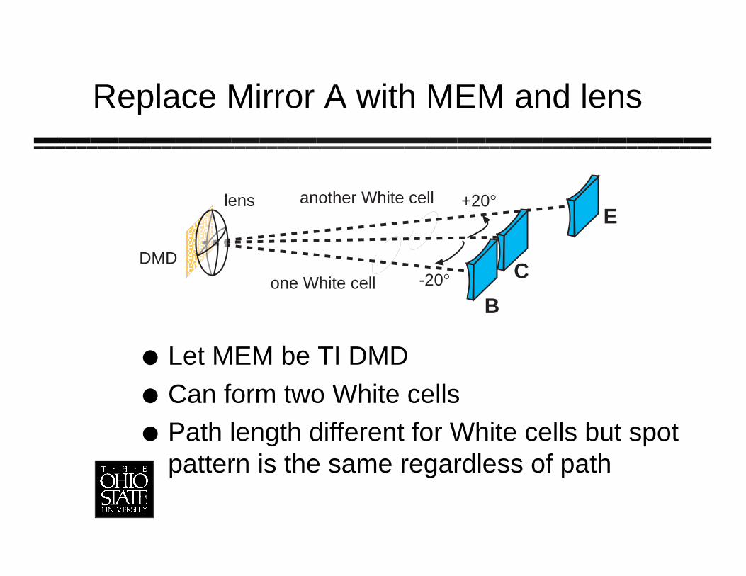
Replace Mirror A with MEM and lens
Let MEM be TI DMDCan form two White cellsPath length different for White cells but spotpattern is the same regardless of path
DMD
+20∞
-20∞
B
C
Elens
one White cell
another White cell
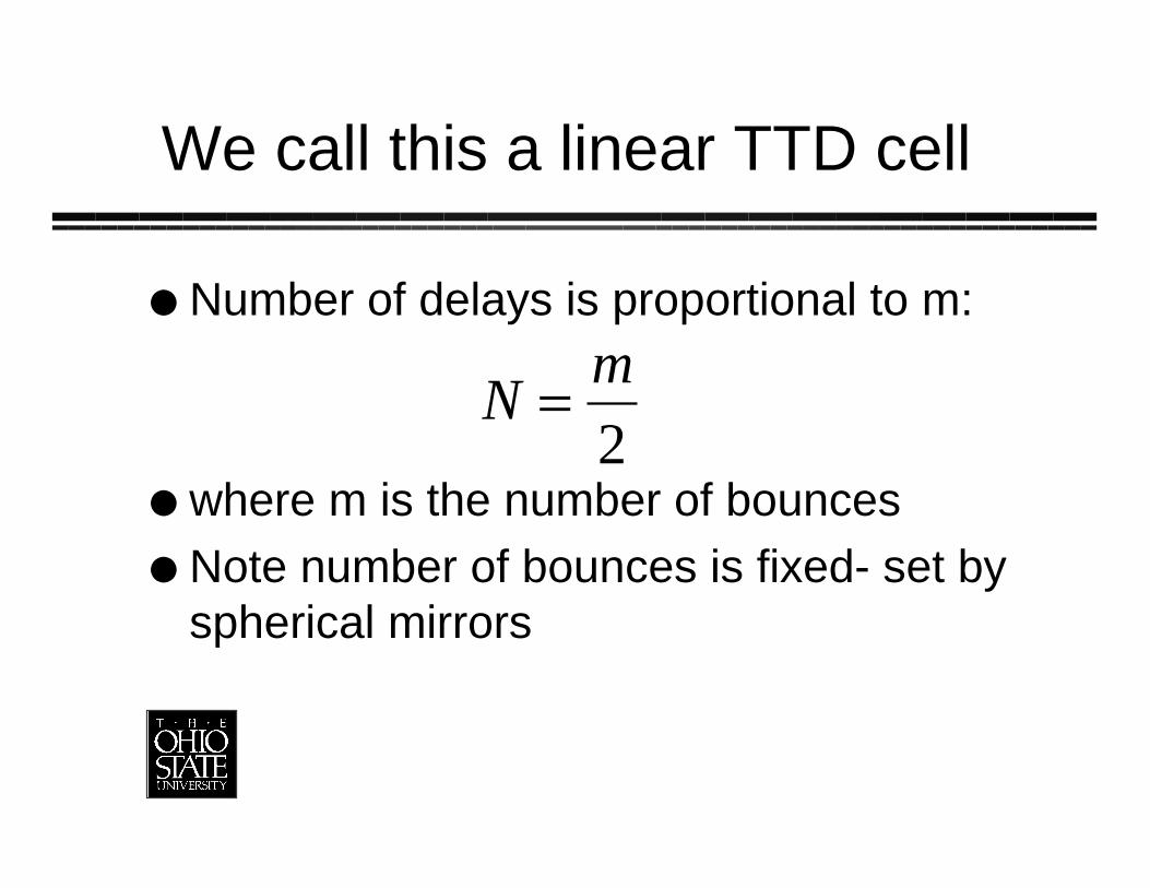
We call this a linear TTD cell
Number of delays is proportional to m:
where m is the number of bouncesNote number of bounces is fixed- set byspherical mirrors
Nm
=2
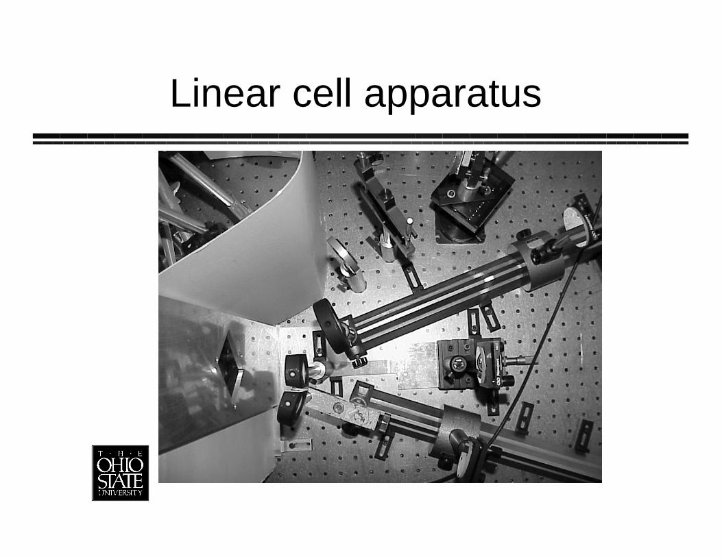
Linear cell apparatus
We built it
Time increment was 1 nsUsed pulsed laser (green) to measure delaysLoss ª 1.2 dB/bounce» Diffraction a big problem
– Pixels smaller (16 mm) than our beam
– We used a 50x50 pixel “macropixel”
– Get diffraction off interpixel gaps and holes in mirrors
» Mirrors are aluminum (gold has higher reflectivity)
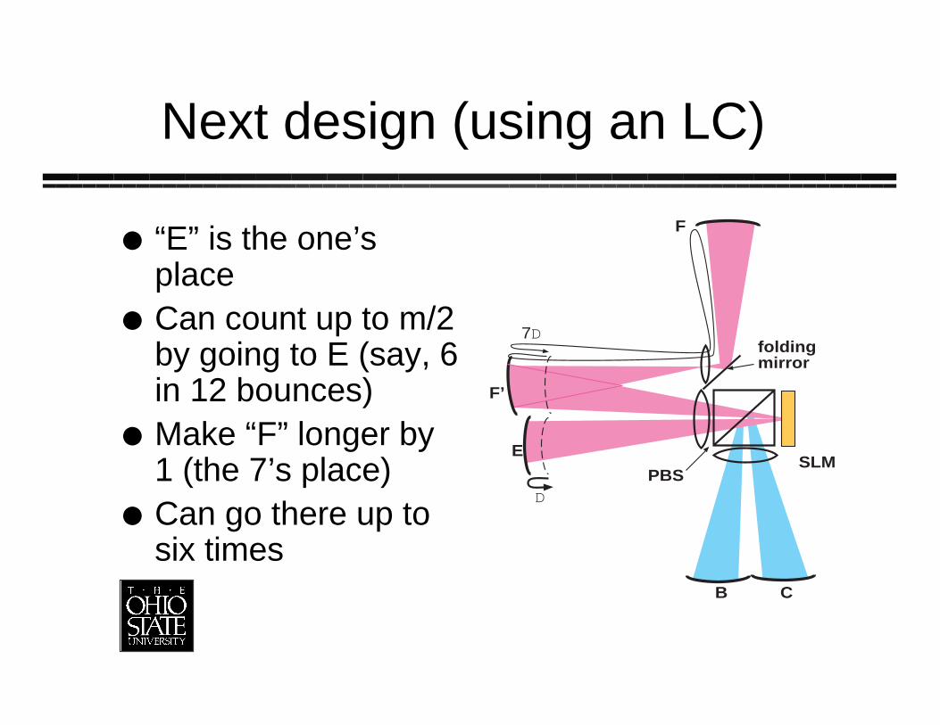
Next design (using an LC)
B C
SLME
F’
F
PBS
foldingmirror
D
7D
“E” is the one’splaceCan count up to m/2by going to E (say, 6in 12 bounces)Make “F” longer by1 (the 7’s place)Can go there up tosix times
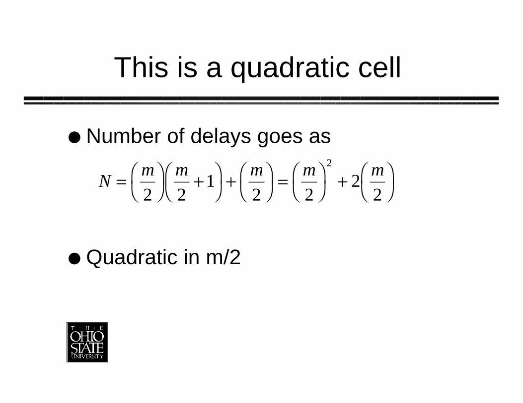
This is a quadratic cell
Number of delays goes as
Quadratic in m/2
Nm m m m m
= ÊË
ˆ¯
+ÊË
ˆ¯
+ ÊË
ˆ¯
= ÊË
ˆ¯
+ ÊË
ˆ¯2 2
12 2
22
2
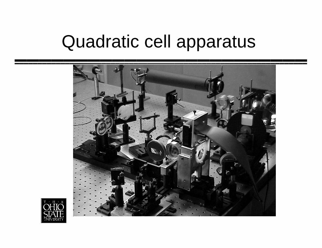
Quadratic cell apparatus
We built it
Used Nd:YAG laser (1319 nm)Time delay increment 1 nsHad four input spots» Fiber array in silicon V-groove
Losses about 1 dB/bounceCrosstalk was lousy (we didn’t specifySLM correctly)
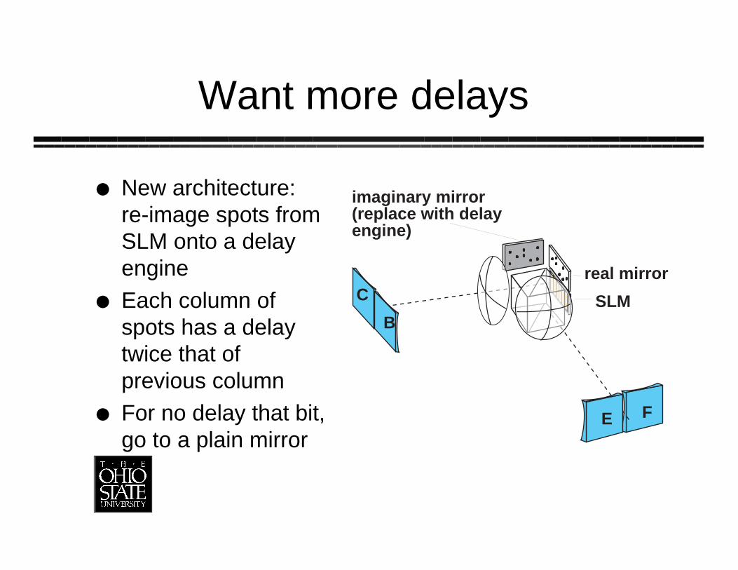
Want more delays
New architecture:re-image spots fromSLM onto a delayengineEach column ofspots has a delaytwice that ofprevious columnFor no delay that bit,go to a plain mirror
C
F
SLM
real mirror
imaginary mirror(replace with delayengine)
E
B
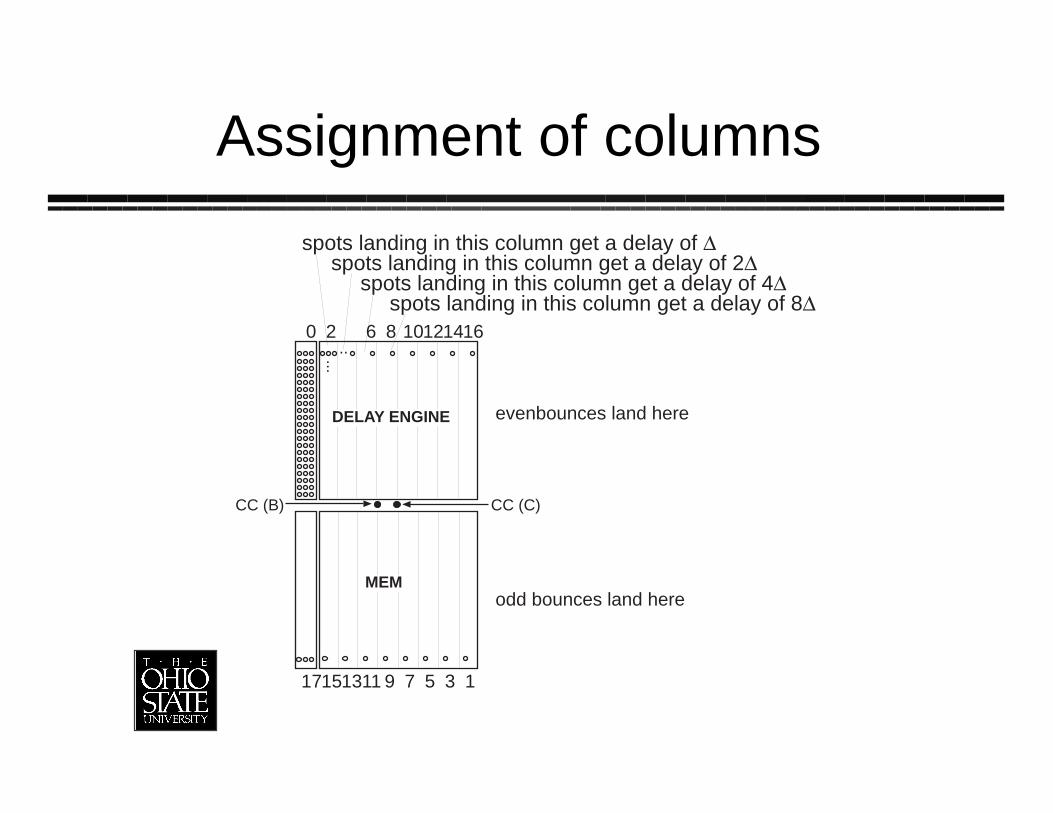
Assignment of columns
0 2 6 8 10121416
1357911131517
CC (B) CC (C)
...
..
MEM
DELAY ENGINE evenbounces land here
odd bounces land here
spots landing in this column get a delay of Dspots landing in this column get a delay of 2D
spots landing in this column get a delay of 4Dspots landing in this column get a delay of 8D
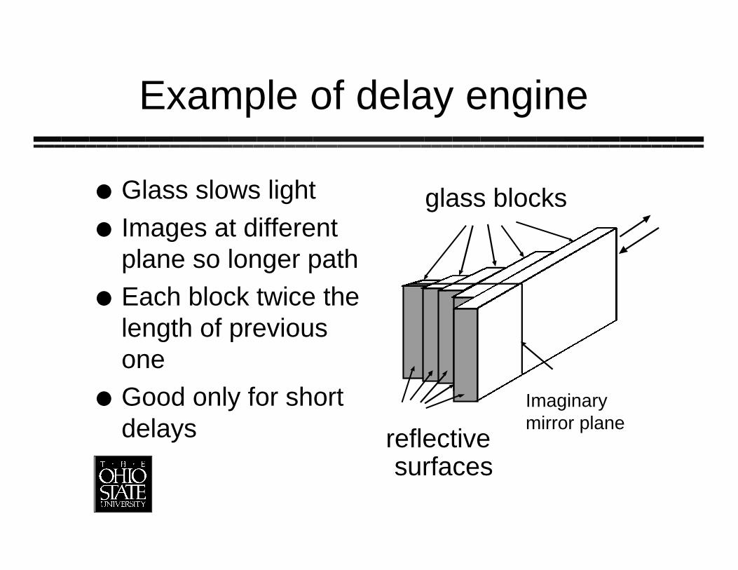
Example of delay engine
Glass slows lightImages at differentplane so longer pathEach block twice thelength of previousoneGood only for shortdelays
glass blocks
Imaginarymirror plane
reflectivesurfaces
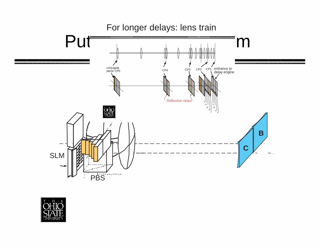
Put that into the system
E F
C
B
SLM
PBS
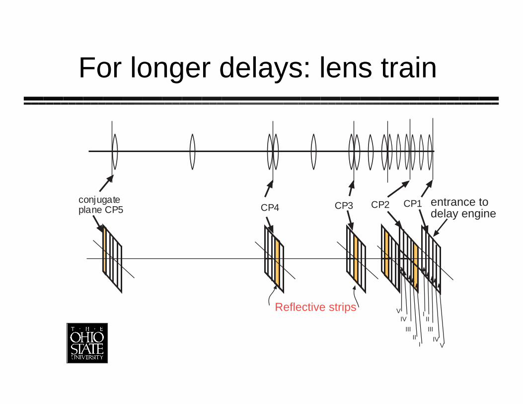
For longer delays: lens train
conjugateplane CP5 CP4 CP3 CP2 CP1
III
III
IVV
IIIII
IVV
I
Reflective strips
entrance todelay engine
For longer delays: lens train
conjugateplane CP5 CP4 CP3 CP2 CP1
III
III
IVV
IIIII
IVV
I
Reflective strips
entrance todelay engine
We’re building that
Liquid crystal SLM1319 nm light7 bits in glass blocks (1 ps up to 128 ps)6 bits in lens train (512 ps up to 16.4 ns)

Glass block results
Used PMMA (faster, cheaper)Vendor unable to make without twisting,warpingHave not put resulting transporteraccident into system yet
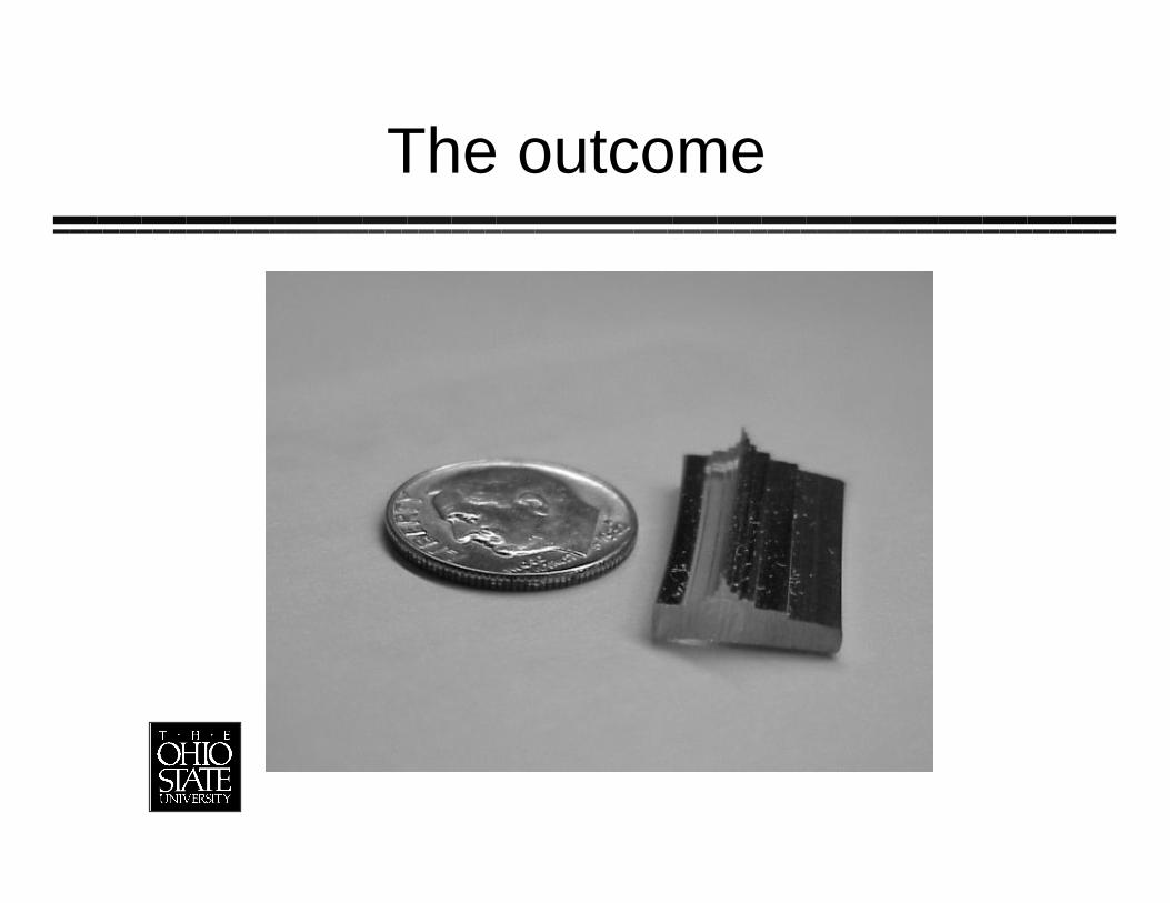
The outcome
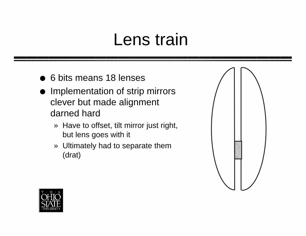
Lens train
6 bits means 18 lensesImplementation of strip mirrorsclever but made alignmentdarned hard» Have to offset, tilt mirror just right,
but lens goes with it» Ultimately had to separate them
(drat)
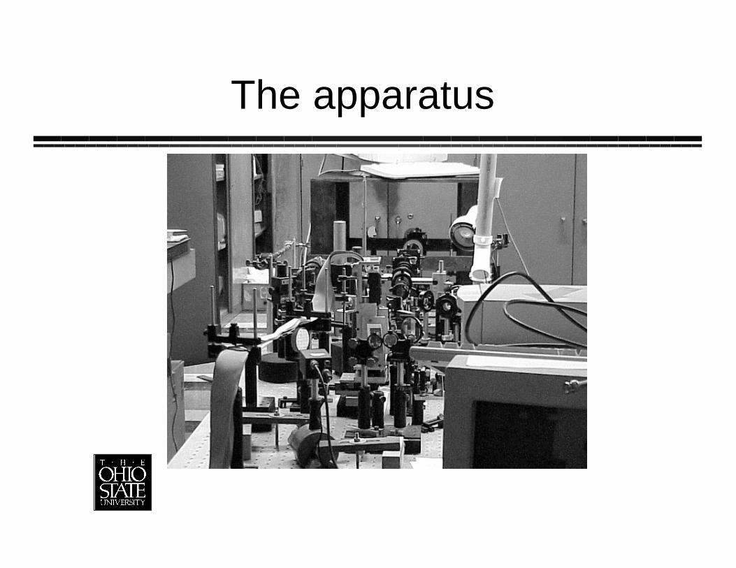
The apparatus
Lens Train
Got it all aligned at visible» Image SLM to every mirror plane» Image every field lens onto every other
Now re-aligning at infraredNo data yet
But we’re still looking ahead
Next: present some designs for higherorder cellsTwo flavors:» Polynomial (like quadratic), where Nµmx
» Exponential (like binary) where N µxm
New designs use MEM’s
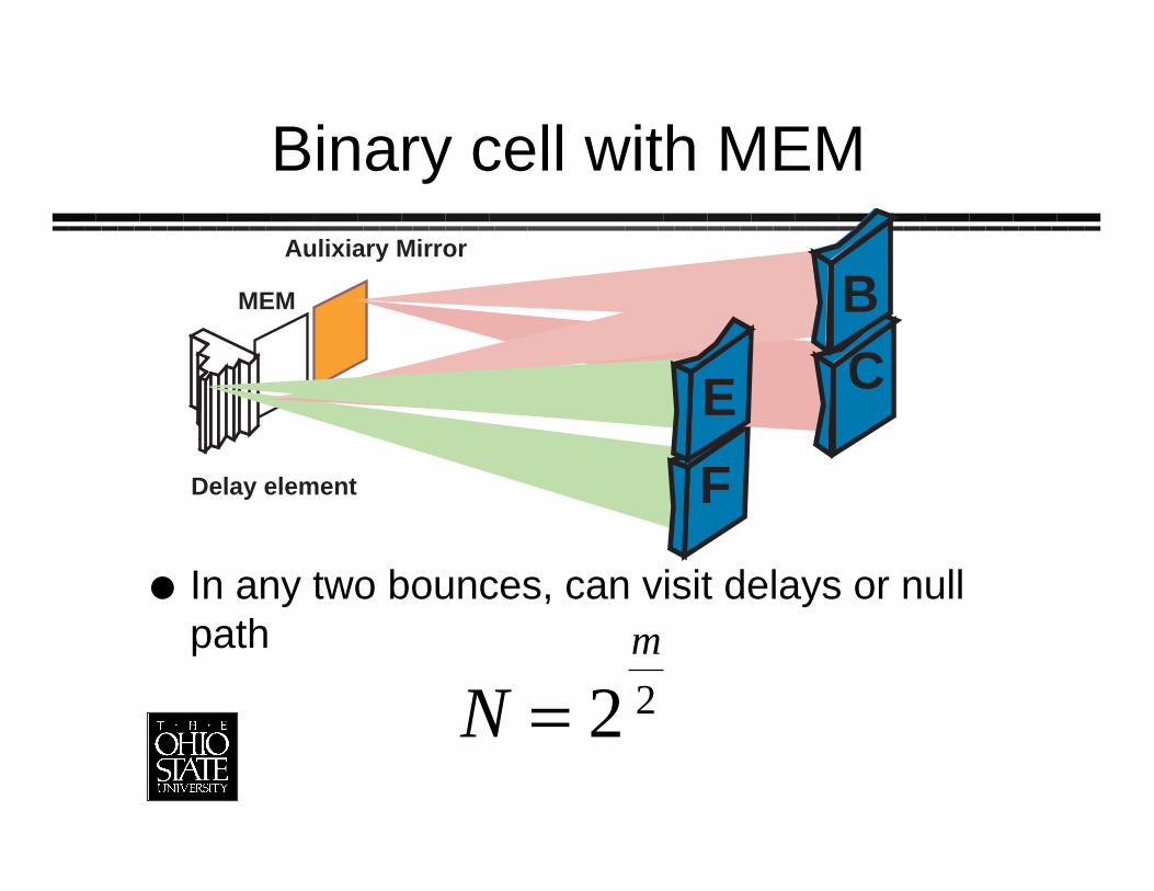
Binary cell with MEM
In any two bounces, can visit delays or nullpath
Nm
= 2 2
FDelay element
MEM
Aulixiary Mirror
CB
E
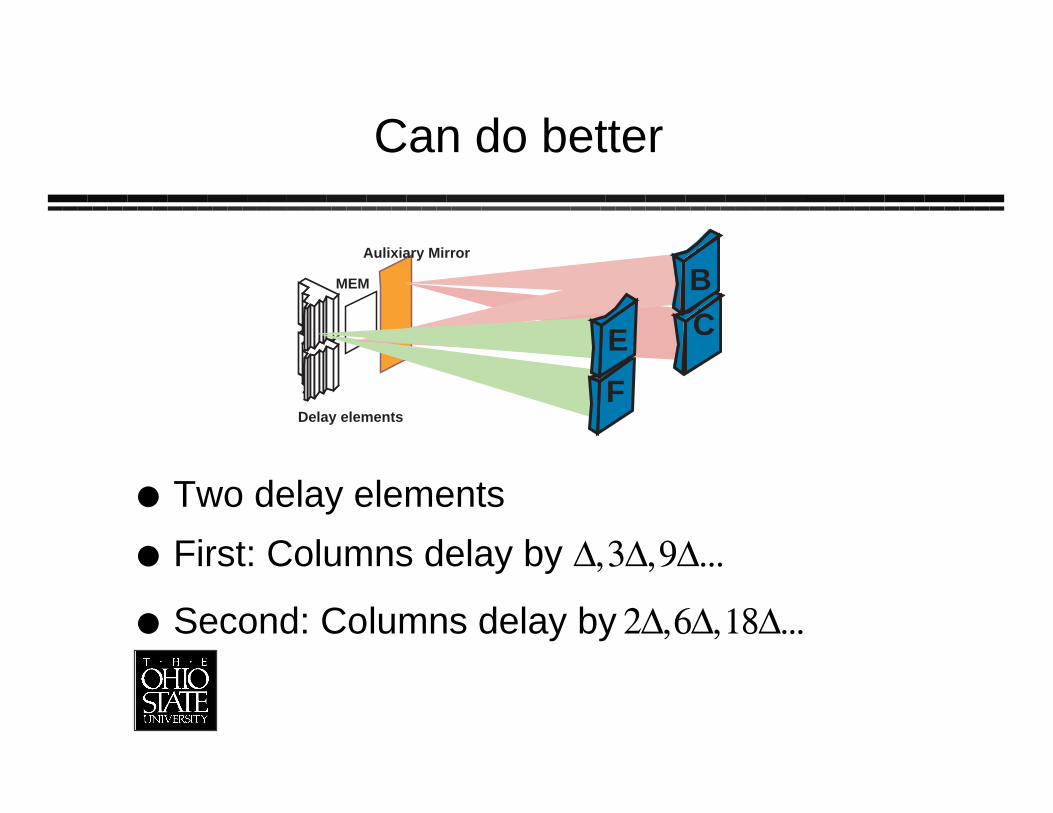
Can do better
Two delay elements
First: Columns delay by D, 3D, 9D...
Second: Columns delay by 2D, 6D, 18D...
FDelay elements
MEM
Aulixiary Mirror
CB
E
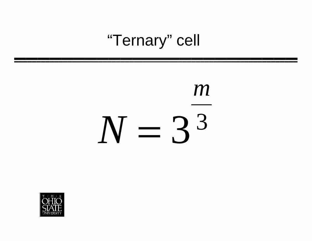
“Ternary” cell
Nm
= 3 3
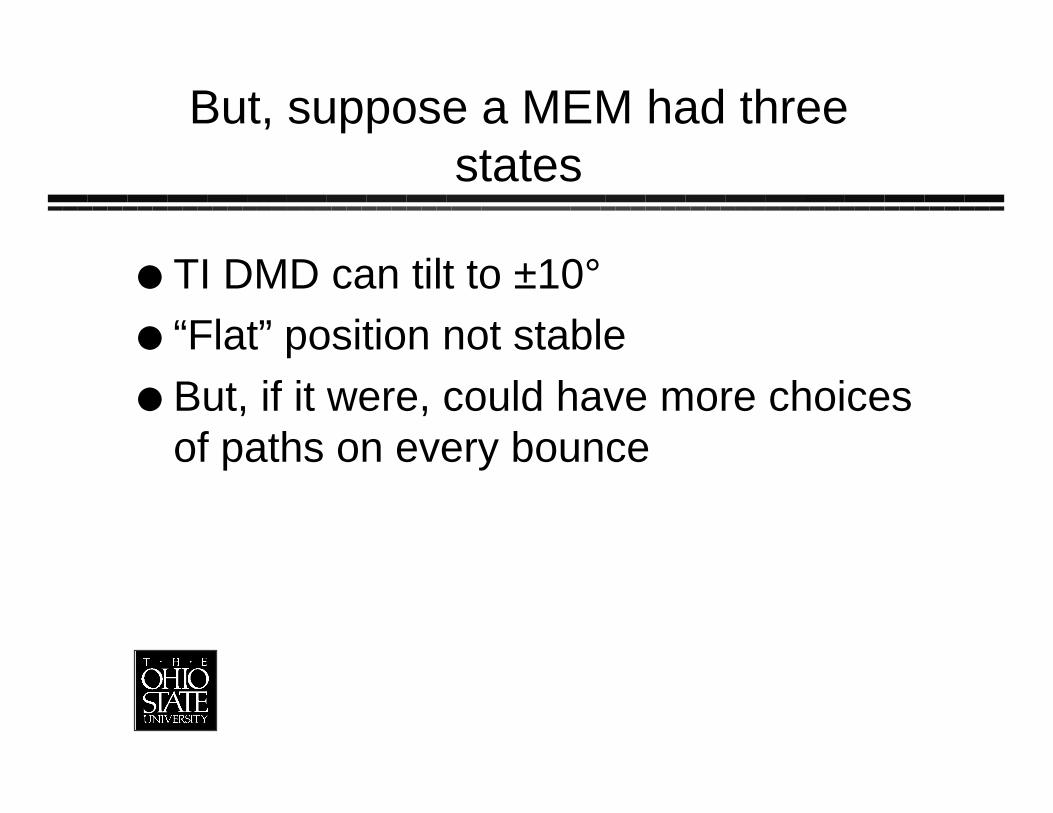
But, suppose a MEM had threestates
TI DMD can tilt to ±10°“Flat” position not stableBut, if it were, could have more choicesof paths on every bounce
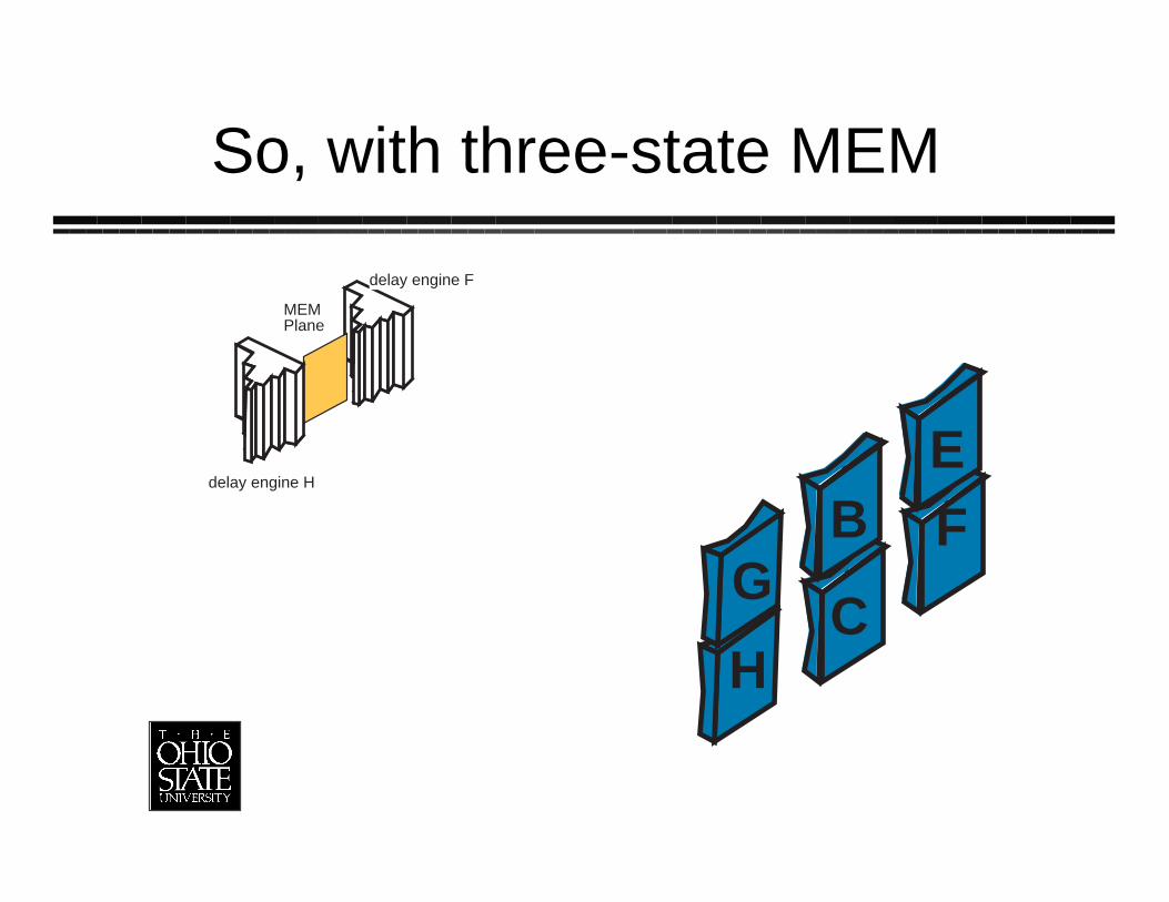
So, with three-state MEM
delay engine F
MEMPlane
delay engine H
H
GFE
B
C
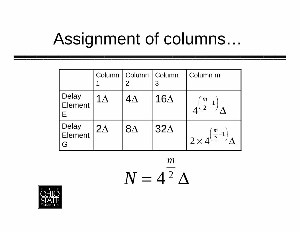
Assignment of columns…
32D8D2DDelayElementG
16D4D1DDelayElementE
Column mColumn3
Column2
Column1
4 21
m-Ê
ˈ¯ D
2 4 21
¥-Ê
ˈ¯
m
D
Nm
= 4 2 D
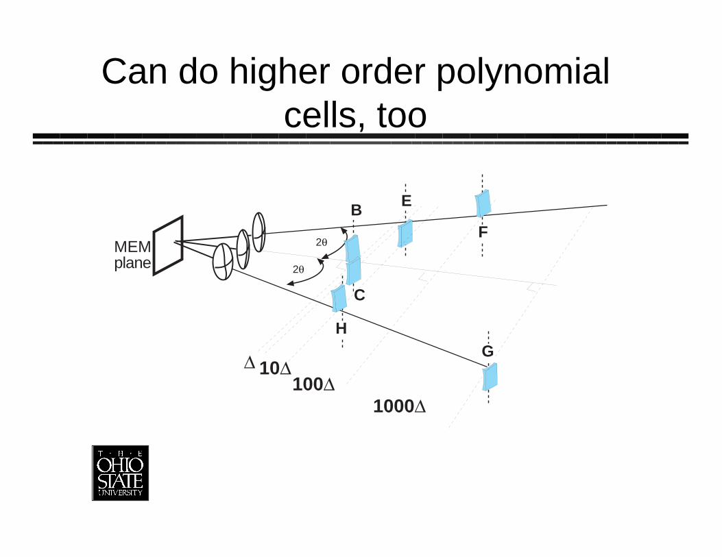
Can do higher order polynomialcells, too
2q
2q
MEMplane
C
B E
G
F
H
D 10D100D
1000D
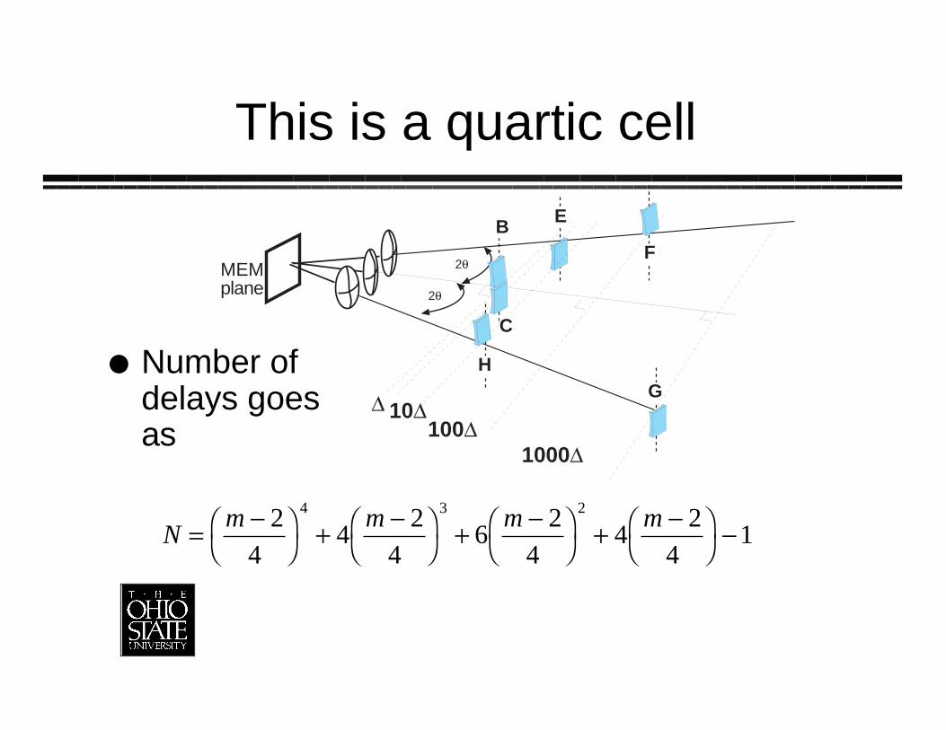
This is a quartic cell
Number ofdelays goesas
2q
2q
MEMplane
C
B E
G
F
H
D 10D100D
1000D
Nm m m m
=-Ê
ˈ¯
+-Ê
ˈ¯
+-Ê
ˈ¯
+-Ê
ˈ¯
-2
44
24
62
44
24
14 3 2
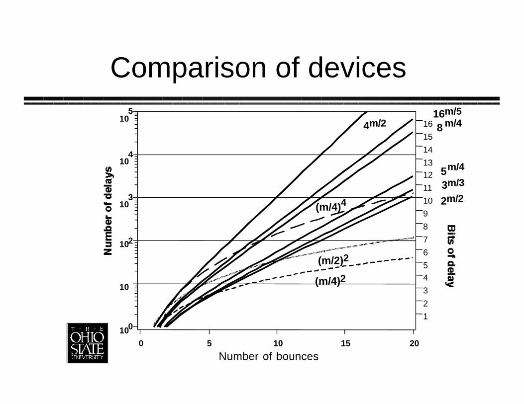
Comparison of devices
100
10
102
103
104
105
20151050
Number of bounces
(m/4)2
(m/4)4
(m/2)2
2m/2
16m/5
8 m/4
5m/4
3m/3
4m/2
1
2
3
45
6
7
8
9
10
11
1213
14
15
16
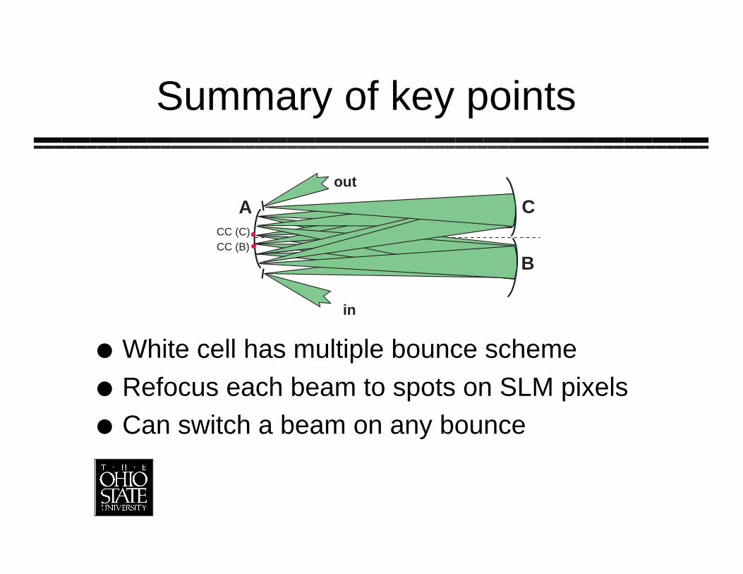
Summary of key points
White cell has multiple bounce schemeRefocus each beam to spots on SLM pixelsCan switch a beam on any bounce
A
B
C
in
out
CC (B)CC (C)
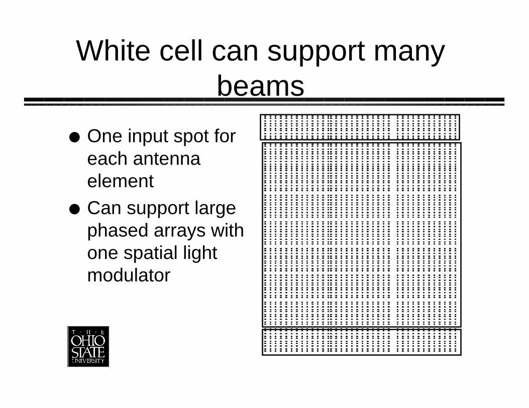
White cell can support manybeams
One input spot foreach antennaelementCan support largephased arrays withone spatial lightmodulator
Got to keep m down
Lots of loss each bounce (ª1dB withcurrent SLM’s)» Almost all of loss due to SLM, not other
components» Need MEM’s with gold mirrors
Need to get a lot of delays for smallnumber of bouncesLed us to various designs
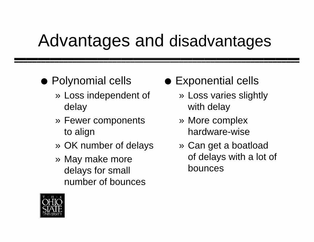
Advantages and disadvantages
Polynomial cells» Loss independent of
delay» Fewer components
to align» OK number of delays» May make more
delays for smallnumber of bounces
Exponential cells» Loss varies slightly
with delay» More complex
hardware-wise» Can get a boatload
of delays with a lot ofbounces