Embed Size (px)
Citation preview

Lecture 15 CM3110 Morrison 10/28/2015
1
© Faith A. Morrison, Michigan Tech U.
CM3110 Transport IPart I: Fluid Mechanics
1
More Complicated Flows III: Boundary-Layer Flow
Professor Faith Morrison
Department of Chemical EngineeringMichigan Technological University
(plus Miscellaneous topics)
© Faith A. Morrison, Michigan Tech U.
More complicated flows II
Solving never-before-solved problems.
Powerful:
Left to explore:
• What is non-creeping flow like?
• Viscosity dominates in creeping flow, what about the flow where inertia dominates?
• What about mixed flows (viscous+inertial)?
• What about really complex flows (curly)?
(boundary layers)
(potential flow)
(boundary layers)
(vorticity, irrotational+circulation)
2

Lecture 15 CM3110 Morrison 10/28/2015
2
© Faith A. Morrison, Michigan Tech U.
More complicated flows II
Solving never-before-solved problems.
Powerful:
Left to explore:
• What is non-creeping flow like?
• Viscosity dominates in creeping flow, what about the flow where inertia dominates?
• What about mixed flows (viscous+inertial)?
• What about really complex flows (curly)?
(potential flow)
(boundary layers)
(vorticity, irrotational+circulation)
3
(boundary layers)
Steady flow of an incompressible, Newtonian fluid around a sphere
McCabe et al., Unit Ops of Chem Eng, 5th edition, p147
Re
24
graphical correlation
© Faith A. Morrison, Michigan Tech U.
4
=Creeping flow
Lecture 15 CM3110 Morrison 10/28/2015
3
© Faith A. Morrison, Michigan Tech U.
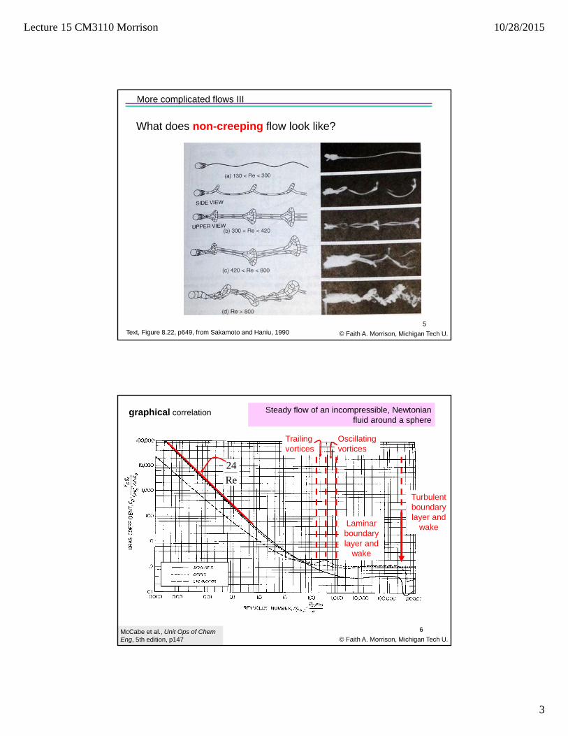
More complicated flows III
5
What does non-creeping flow look like?
Text, Figure 8.22, p649, from Sakamoto and Haniu, 1990
Steady flow of an incompressible, Newtonian fluid around a sphere
McCabe et al., Unit Ops of Chem Eng, 5th edition, p147
graphical correlation
© Faith A. Morrison, Michigan Tech U.
6
Re
24
Trailing vortices
Oscillating vortices
Turbulent boundary layer and
wakeLaminar boundary layer and
wake

Lecture 15 CM3110 Morrison 10/28/2015
4
© Faith A. Morrison, Michigan Tech U.
More complicated flows II
Solving never-before-solved problems.
Powerful:
Left to explore:
• What is non-creeping flow like?
• Viscosity dominates in creeping flow, what about the flow where inertia dominates?
• What about mixed flows (viscous+inertial)?
• What about really complex flows (curly)?
(potential flow)
(boundary layers)
(vorticity, irrotational+circulation)
`7
(boundary layers)
Nondimensional Navier-Stokes Equation:
*
** ** 22
v gDv v P v g
t VD V
© Faith A. Morrison, Michigan Tech U.
8
With the appropriate terms in spherical
coordinates
*
** ** 21 1
Re
vv v P v g
t Fr
→ ∞ No free surfaces
Flow where Inertia Dominates:
Consider the high Re limit:
Now solve for a sphere
∗
∗

Lecture 15 CM3110 Morrison 10/28/2015
5
© Faith A. Morrison, Michigan Tech U.
9
Potential flow around a Sphere (high Re, no viscosity)
∗ ⋅ ∗ 0
2 ∗ cos ∗ sin
(equation 8.203)
1 cos
112
sin
0
Solution:
(equation 8.238-9)
,12
2 132sin 1
34sin
∗
∗ ⋅ ∗∗
∗
© Faith A. Morrison, Michigan Tech U.
10
Potential flow around a Sphere (high Re, no viscosity)
1 cos
112
sin
0
Solution:
(equation 8.238-9)
How does this compare to what we see at high
Re?
∗ ⋅ ∗ 0
2 ∗ cos ∗ sin
(equation 8.203)
,12
2 132sin 1
34sin
∗
∗ ⋅ ∗∗
∗

Lecture 15 CM3110 Morrison 10/28/2015
6
© Faith A. Morrison, Michigan Tech U.
11
Potential flow around a Sphere (high Re, no viscosity)
Solution:
How does this compare to what we see at high
Re?
© Faith A. Morrison, Michigan Tech U.
12
Potential flow around a Sphere (high Re, no viscosity)
Solution:
How does this compare to what we see at high
Re?

Lecture 15 CM3110 Morrison 10/28/2015
7
© Faith A. Morrison, Michigan Tech U.
13
Potential flow around a Sphere (high Re, no viscosity)
Solution:
How does this compare to what we see at high
Re?
∗ ⋅ ∗ 0
2 ∗ cos ∗ sin
(equation 8.203)
,12
2 132sin 1
34sin
∗
∗ ⋅ ∗∗
∗
© Faith A. Morrison, Michigan Tech U.
14
Potential flow around a Sphere (high Re, no viscosity)
1 cos
112
sin
0
Solution:
(equation 8.238-9)

Lecture 15 CM3110 Morrison 10/28/2015
8
∗ ⋅ ∗ 0
2 ∗ cos ∗ sin
(equation 8.203)
,12
2 132sin 1
34sin
∗
∗ ⋅ ∗∗
∗
© Faith A. Morrison, Michigan Tech U.
15
2 ∗ cos ∗ sin
(equation 8.203)
1 cos
112
sin
0
Solution:
(equation 8.238-9)
Wrong!Predicts:
• No drag (d’Alembert’s paradox)
• Slip at the wall
• Approximately right pressure profile (near the wall)
• Right velocity field away from the wall
Potential flow around a Sphere (high Re, no viscosity)
∗ ⋅ ∗ 0
2 ∗ cos ∗ sin
(equation 8.203)
,12
2 132sin 1
34sin
∗
∗ ⋅ ∗∗
∗
© Faith A. Morrison, Michigan Tech U.
16
1 cos
112
sin
0
Solution:
(equation 8.238-9)
Wrong!Predicts:
• No drag
• Slip at the wall
• Approximately right pressure profile (near the wall)
• Right velocity field away from the wall
Potential flow around a Sphere (high Re, no viscosity)

Lecture 15 CM3110 Morrison 10/28/2015
9
© Faith A. Morrison, Michigan Tech U.
More complicated flows III
17
Prandtl’s Great Idea (1904):
• Keep the good parts of the potential flow solution: in free stream, , near the surface
• Throw away the bad parts: slip at the wall
• Solve a new problem near the wall with , from the potential-flow solution
Boundary Layer Theory
© Faith A. Morrison, Michigan Tech U.
More complicated flows III
18
Boundary Layer Theory
• Choose simplest boundary layer (flat plate)
• Nondimensionalize Navier-Stokes
• Eliminate small terms
• Solve⋅
Characteristic values:
in principal flow direction
in direction perpendicular to wall,
length of plate for
boundary layer thickness for
(Section 8.2)

Lecture 15 CM3110 Morrison 10/28/2015
10
© Faith A. Morrison, Michigan Tech U.
More complicated flows III
19
Boundary Layer Theory
• Choose simplest boundary layer (flat plate)
• Nondimensionalize Navier-Stokes
• Eliminate small terms
• Solve⋅
Characteristic values:
in principal flow direction
in direction perpendicular to wall,
length of plate for
boundary layer thickness for
(Section 8.2)
Note that for this flow, two length scales and two velocities were found to be
appropriate for the dimensional analysis.
© Faith A. Morrison, Michigan Tech U.
More complicated flows III
20
Boundary Layer Theory
• Apply to uniform flow approaching a sphere
It works!(see text, p710)
Boundary layer velocity profiles as you progress from the stagnation point (0 to the top of the sphere (90 ) and beyond.

Lecture 15 CM3110 Morrison 10/28/2015
11
© Faith A. Morrison, Michigan Tech U.
More complicated flows III
21
Boundary Layer Theory
• Explains boundary-layer separation
• Golf ball problem
• BL separation caused by adverse pressure gradient
It works!
H. Schlichting, Boundary Layer Theory (McGraw-Hill, NY 1955.
smooth ball rough ball
pressure slows the flow and causes reversal
pressure pushes flow along
© Faith A. Morrison, Michigan Tech U.
More complicated flows III
22
Boundary Layer Theory
• Explains boundary-layer separation
• Golf ball problem
• BL separation caused by adverse pressure gradient
It works!
H. Schlichting, Boundary Layer Theory (McGraw-Hill, NY 1955.
smooth ball rough ball
pressure slows the flow and causes reversal
pressure pushes flow along
The pressure distribution is like a storage mechanism for momentum in the flow; as other momentum sources die out, the pressure drives the flow.

Lecture 15 CM3110 Morrison 10/28/2015
12
Re
24
Trailing vortices
Oscillating vortices
Turbulent boundary layer and
wakeLaminar boundary layer and
wake
Steady flow of an incompressible, Newtonian fluid around a sphere
McCabe et al., Unit Ops of Chem Eng, 5th edition, p147
graphical correlation
© Faith A. Morrison, Michigan Tech U.
23
© Faith A. Morrison, Michigan Tech U.
24
What did we do?
Same strategy as:
• Turbulent tube flow
• Noncircular conduits
• Drag on obstacles
1. Find a simple problem that allows us to identify the physics
2. Nondimensionalize
3. Explore that problem
4. Take data and correlate
5. Solve real problems
Solve Real Problems.
Powerful.

Lecture 15 CM3110 Morrison 10/28/2015
13
© Faith A. Morrison, Michigan Tech U.
More complicated flows II
Solving never-before-solved problems.
Powerful:
Left to explore:
• What is non-creeping flow like?
• Viscosity dominates in creeping flow, what about the flow where inertia dominates?
• What about mixed flows (viscous+inertial)?
• What about really complex flows (curly)?
(boundary layers)
(potential flow)
(boundary layers)
(vorticity, irrotational+circulation)
25
See text
CM3110 Transport IPart I: Fluid Mechanics
26
Miscellaneous Topics
Fluidized Beds
Professor Faith Morrison
Department of Chemical EngineeringMichigan Technological University
© Faith A. Morrison, Michigan Tech U.

Lecture 15 CM3110 Morrison 10/28/2015
14
Fluidized beds
© Faith A. Morrison, Michigan Tech U.
ChemE Application of Ergun Equation
•ion exchange columns•packed bed reactors•packed distillation columns•filtration
Image from: fluidizedbed2008.webs.com
27
•flow through soil (environmental issues, enhanced oil recovery)•fluidized bed reactors
ChemE Application of Ergun Equation
Calculate the minimum superficial velocity at which a bed becomes fluidized.
flow
In a fluidized bed reactor, the flow rate of the gas is adjusted to overcome the force of gravity and fluidize a bed of particles; in this state heat and mass transfer is good due to the chaotic motion. v
pp
f 75.1Re
150The Δ vs Q
relationship can come from the Ergun eqn at
small Repneglect
28© Faith A. Morrison, Michigan Tech U.
dominates
note: Re vs Re

Lecture 15 CM3110 Morrison 10/28/2015
15
Now we perform a force balance on the bed:
More Complex Applications II: Fluidized beds
pressure(Ergun eqn)
gravity
buoyancy
net effect of gravity and
buoyancy is:When the forces balance, incipient
fluidization
© Faith A. Morrison, Michigan Tech U.
1
bed volume 1
Δ 29
Flow Through Noncircular Conduits – All Flow Regimes
Ergun equation:
100/3 1.753
(flow through porous media)
30
© Faith A. Morrison, Michigan Tech U.note: Re vs Re

Lecture 15 CM3110 Morrison 10/28/2015
16
When the forces balance, incipient fluidization
eliminate Δ ; solve for
velocity at the point of incipient fluidization
© Faith A. Morrison, Michigan Tech U.
Δ 1
150
150 1
Complete solution steps in Denn, Process Fluid Mechanics (Prentice Hall, 1980)
More Complex Applications II: Fluidized beds
31
note: Re vs Re
CM3110 Transport IPart I: Fluid Mechanics
32
Miscellaneous Topics
Compressible Flow
Professor Faith Morrison
Department of Chemical EngineeringMichigan Technological University
© Faith A. Morrison, Michigan Tech U.

Lecture 15 CM3110 Morrison 10/28/2015
17
Compressible Fluids
•most fluids are somewhat compressible
•in chemical-engineering processes, compressibility is unimportant at most operating pressures
•even gases may be modeled as incompressible if Δ
EXCEPT:When the fluid velocity approaches the speed of sound
© Faith A. Morrison, Michigan Tech U.
How is pressure information transmitted in liquids and gases?
The Hydraulic Lift operates on Pascal’s principle 2ra 2rb
fluid of density
Fa Fb
a b
lbFb
c dla
Fca b
Pressure exerted on an enclosed liquid is transmitted equally to every part of the liquid and to the walls of the container.
Compressible Fluids
© Faith A. Morrison, Michigan Tech U.
Lecture 15 CM3110 Morrison 10/28/2015
18
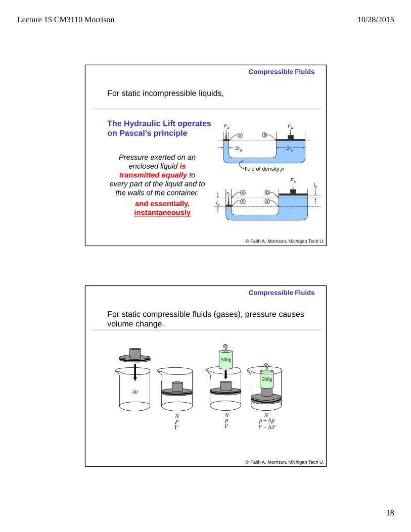
The Hydraulic Lift operates on Pascal’s principle
2ra 2rb
fluid of density
Fa Fb
a b
lbFb
c dla
Fca b
Pressure exerted on an enclosed liquid is
transmitted equally to every part of the liquid and to
the walls of the container.
and essentially, instantaneously
For static incompressible liquids,
Compressible Fluids
© Faith A. Morrison, Michigan Tech U.
For static compressible fluids (gases), pressure causes volume change.
air
Vp
N
500g
500g
VVpp
Vp
N N
Compressible Fluids
© Faith A. Morrison, Michigan Tech U.

Lecture 15 CM3110 Morrison 10/28/2015
19
For moving incompressible liquids and gases,
flow
The presence of the obstacle is felt by the upstream fluid (pressure) and that information is transmitted very rapidly throughout the fluid.
The streamlines adjust according to momentum conservation.
Compressible Fluids
© Faith A. Morrison, Michigan Tech U.
For compressible fluids moving near sonic speeds, information(pressure) and the gas itself are moving at comparable speeds.
Shock wavePressure
piles up at the shock
wave
Compressible Fluids
© Faith A. Morrison, Michigan Tech U.

Lecture 15 CM3110 Morrison 10/28/2015
20
Compressible Fluids
Velocity of a pressure wave = constant = speed
of soundVelocity of a fluid = variable = supersonic, sonic, subsonic
A shock forms where the pressure waves from the obstacle stack up, and the speed of the pressure wave traveling upstream equals the speed of the fluid traveling downstream.
© Faith A. Morrison, Michigan Tech U.
tank
The rapid flows in relief valves can become sonic. For supersonic flow, the
flow rate is constant no matter what the pressure drop is.
(pressure waves pile up)
Relief Valves (Safety Valves)
Choked Flow
Choked flow can be understood from basic equations of compressible fluid mechanics.
Compressible Fluids
© Faith A. Morrison, Michigan Tech U.

Lecture 15 CM3110 Morrison 10/28/2015
21
Momentum and Energy in Compressible Fluids
vv v p g
t
Microscopic momentum balance:
incompressible
Mechanical energy balance:incompressible
compressible?
Compressible Fluids
© Faith A. Morrison, Michigan Tech U.
~
Δ Δ2
,
Momentum and Energy in Compressible Fluids
vv v p g
t
Microscopic momentum balance:
vvv T
3
2
incompressible
compressible = bulk viscosity
Mechanical energy balance:incompressible
MEB for compressible?
Compressible Fluids
© Faith A. Morrison, Michigan Tech U.
~
~
Δ Δ2
,

Lecture 15 CM3110 Morrison 10/28/2015
22
© Faith A. Morrison, Michigan Tech U.
Mechanical energy balance (compressible)
Back up one step in the derivation and reintegrate without constant assumption.
m
dWdFgdzVdV
dp ons
,
Assume:•constant cross section•constant mass flow •neglect gravity•no shaft work
velocitymassVG
Compressible Fluids
© Faith A. Morrison, Michigan Tech U.
Mechanical energy balance(compressible)
pM
RTpM
RT
MN
Vp
RT
N
VNRTpV
1
Ideal Gas Law For isothermal flow:
1
2
2
1
22
11
V
V
p
pNRTVpNRTVp
Also,
RT
M
pp
RT
M
p
av
av
av
21
2
Compressible Fluids

Lecture 15 CM3110 Morrison 10/28/2015
23
Mechanical energy balance(compressible)
02
ln 12
2
2
12
12 LLD
fG
p
pGpp
avav
The compressible MEB predicts that there is a maximum velocity at
sound of speed isothermal2
2max
M
RTpV
(see book)
velocitymassVG
Compressible Fluids
© Faith A. Morrison, Michigan Tech U.
A better assumption than isothermal flow is adiabatic flow (no heat transferred). For this case,
v
p
C
Cγ
M
RTpV
sound of speed adiabatic2
2max
(see book)
Compressible Fluids
© Faith A. Morrison, Michigan Tech U.

Lecture 15 CM3110 Morrison 10/28/2015
24
© Faith A. Morrison, Michigan Tech U.
47
Done!
Just one more thing
© Faith A. Morrison, Michigan Tech U.48
Numerical PDE Solving with Comsol 5.1
1. Choose the physics (2D, 2D axisymmetric, laminar, steady/unsteady, etc.)
2. Choose flow geometry and fluid (shape of the flow domain)
3. Define boundary conditions
4. Design and generate mesh
5. Solve the problem
6. Calculate and plot engineering quantities of interest.
www.comsol.com
Finite‐element numerical differential equation solver. Applications include fluid mechanics and heat transfer.

Lecture 15 CM3110 Morrison 10/28/2015
25
© Faith A. Morrison, Michigan Tech U.
Comsol Multiphysics 5.1 0Launch the program
(actually, these screen shots are from Comsol 4.2)
© Faith A. Morrison, Michigan Tech U.
1Choose the physicsComsol Multiphysics 5.1
(actually, these screen
shots are from Comsol 4.2)

Lecture 15 CM3110 Morrison 10/28/2015
26
© Faith A. Morrison, Michigan Tech U.
2Choose flow geometry and fluidComsol Multiphysics 5.1
(actually, these screen
shots are from Comsol 4.2)
© Faith A. Morrison, Michigan Tech U.
3Define boundary conditionsComsol Multiphysics 5.1
(actually, these screen
shots are from Comsol 4.2)

Lecture 15 CM3110 Morrison 10/28/2015
27
© Faith A. Morrison, Michigan Tech U.
4Design and generate meshComsol Multiphysics 5.1
(actually, these screen
shots are from Comsol 4.2)
© Faith A. Morrison, Michigan Tech U.
5Solve the problemComsol Multiphysics 5.1
(actually, these screen
shots are from Comsol 4.2)

Lecture 15 CM3110 Morrison 10/28/2015
28
© Faith A. Morrison, Michigan Tech U.
5View the solutionComsol Multiphysics 5.1
(actually, these screen
shots are from Comsol 4.2)
© Faith A. Morrison, Michigan Tech U.
6Calculate engineering problems of interest
Comsol Multiphysics 5.1
(actually, these screen
shots are from Comsol 4.2)

Lecture 15 CM3110 Morrison 10/28/2015
29
© Faith A. Morrison, Michigan Tech U.
Comsol Multiphysics
Comsol project:
• Due last day of classes
• Individual work
• 2 points for part 1 (instructions given)
• 3 points for part 2 (no instructions)
• Coming soon
Adds on top of your course grade
CM3110 Transport IPart II: Heat Transfer
58
Introduction to Heat Transfer
Professor Faith Morrison
Department of Chemical EngineeringMichigan Technological University
© Faith A. Morrison, Michigan Tech U.