Embed Size (px)
Citation preview

Morphological and mechanical investigation of double
layer reciprocal structures
Cyril Douthe, Olivier Baverel
To cite this version:
Cyril Douthe, Olivier Baverel. Morphological and mechanical investigation of double layerreciprocal structures. IASS 2013 Symposium, Sep 2013, Poland. 12 p., 2013. <hal-00938752>
HAL Id: hal-00938752
https://hal.archives-ouvertes.fr/hal-00938752
Submitted on 29 Jan 2014
HAL is a multi-disciplinary open accessarchive for the deposit and dissemination of sci-entific research documents, whether they are pub-lished or not. The documents may come fromteaching and research institutions in France orabroad, or from public or private research centers.
L’archive ouverte pluridisciplinaire HAL, estdestinee au depot et a la diffusion de documentsscientifiques de niveau recherche, publies ou non,emanant des etablissements d’enseignement et derecherche francais ou etrangers, des laboratoirespublics ou prives.
1
Morphological and mechanical investigation of double layer reciprocal structures
Cyril Douthe1, Olivier Baverel2 3
1Université Paris-Est, IFSTTAR, France, [email protected]
2Université Paris-Est, Laboratoire Navier (ENPC/IFSTTAR/CNRS), France, [email protected] 3ENS Architecture de Grenoble, France
Summary: From a technological point of view, reciprocal structures have the advantage of simplifying considerably connections in the sense that members are connected only by pairs. This constructional advantage has two main consequences: technological constrains are replaced by geometrical constrains and bending moments are increased through the non convergence of members to nodes with multiple connections. Geometrical constrains can be dealt by using form-finding methods such as dynamic relaxation algorithm. However resisting bending moments to gain stiffness is difficult without increasing the weight of the structure. For standard reticulated structures, common strategies consist in introducing curvature in the structure and/or modifying the structure into a double layer space structure. The proposed paper is thus an attempt to apply these strategies to reciprocal structures and to develop spherical domes with structural thickness. Several configurations will be investigated and compared in term of geometrical feasibility and structural performance.
Keywords: Spatial structures, structural morphology, form-finding, dynamic relaxation, linear elastic behaviour.
1. INTRODUCTION From a technological point of view, reciprocal structures have the advantage of simplifying considerably connections in the sense that members are connected only by pairs. This constructional advantage has two main consequences: technological constrains are replaced by geometrical constrains and bending moments are increased through the non convergence of members at nodes with multiple connections. Indeed it has been shown in [1] that the reciprocal structures are softer and generate higher stresses than their conventional counterpart. In order to increase the performances of reciprocal structures, it is proposed here to investigate two basic strategies used for reticulated systems: to introduce curvature and/or to increase the structural thickness. Various configurations of double layer systems will thus be shown in this paper. In the following section, simple configurations where structural thickness is obtained by the elements themselves (Vierendeel trusses or any other space trusses) will be examined. A simple construction made of ladder elements will be shown. Then, in the third section, a solution for building a double layer reciprocal system with a flat configuration is developed based on analytical calculations [2]. In the fourth section, a double layer dome configuration is investigated. The form-finding method using the dynamic relaxation algorithm [1] is detailed and a comparison of the structural behaviour with a simple layer configuration is made. Finally the authors conclude on the potential of double layer reciprocal systems and illustrate their feasibility on a prototype.
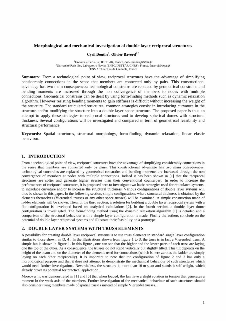
2. DOUBLE LAYER SYSTEMS WITH TRUSS ELEMENTS A possibility for creating double layer reciprocal systems is to use truss elements in standard single layer configuration similar to those shown in [3, 4]. In the illustrations shown from figure 1 to 3, the truss is in fact a Vierendeel truss. A simple fan is shown in figure 1. In this figure , one can see that the higher and the lower parts of each truss are laying one the top of the other. As a consequence, the trusses do not stand vertically but slightly tilted. This tilt depends on the height of the beam and on the diameter of the elements used for connections (which is here zero as the ladder are simply laying on each other reciprocally). It is important to note that the configuration of figure 2 and 3 has only a morphological purpose and that it does not attempt to demonstrate the mechanical behaviour of such structures which would need further investigations. Nevertheless, the structure is more than 10 m span and stands it self-weight, which already prove its potential for practical application.
Moreover, it was demonstrated in [1] and [5] that when loaded, the fan have a slight rotation in torsion that generates a moment in the weak axis of the members. Further investigation of the mechanical behaviour of such structures should also consider using members made of spatial trusses instead of simple Vierendel trusses.
2
Fig. 1: View of a fan composed with three truss elements
Fig. 2: Dome with truss elements
Fig. 3 : Elevation view of a dome with truss element
3. DOUBLE LAYER SYSTEMS WITH SLENDER MEMBERS FOR FLAT CONFIGURATIONS
In the preceding section, the method proposed to obtain a “double layer” structure was to start from a single layer reciprocal structure and to replace slender members by space trusses. In the second method presented here, the double layer reciprocal system is obtained by transformation of a standard double layer spatial structure in a similar way to the transformations studied in [2,4,8]. There are several way to compute practically the final configuration of the reciprocal system after the transformation: some analytical methods have been developed by rotation of members in [2] and [8] and also some numerical methods using genetic algorithm [4] or dynamic relaxation [1]. This section will focus on the analytical method while the next section will make use of the dynamic relaxation algorithm.
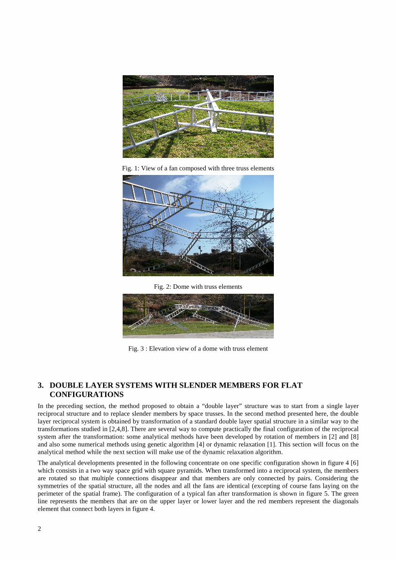
The analytical developments presented in the following concentrate on one specific configuration shown in figure 4 [6] which consists in a two way space grid with square pyramids. When transformed into a reciprocal system, the members are rotated so that multiple connections disappear and that members are only connected by pairs. Considering the symmetries of the spatial structure, all the nodes and all the fans are identical (excepting of course fans laying on the perimeter of the spatial frame). The configuration of a typical fan after transformation is shown in figure 5. The green line represents the members that are on the upper layer or lower layer and the red members represent the diagonals element that connect both layers in figure 4.

3
Fig. 4 : Two way space grid with square pyramid (square on square offset)
Fig. 5 : Plan and perspective view of a fan
The parameters of the model are: the length and engagement length of the members of the upper (or lower) layer, those of the diagonal members and the eccentricity of the connection (or the distance between the axis of two connected members). There are thus 5 design parameters. The strategy for determining analytically the values of these parameters is the same as in [2]:
- write that the direction of the eccentricity between two members is perpendicular to each member,
- write that the distance between two members is equal to the eccentricity,
- write that the distance between two contact points on a member is equal to the engagement length.
- write geometric compatibility between upper and lower fand (which is equivalent to adjusting the diagonal length so that upper and lower fans can effectively be connected).
To ease calculations (which are detailed in [9]), it is supposed that the relative engagement length are equals and that the eccentricity is constant. Under those conditions, it is found that, out-of five parameters, only two are independent: the length of the upper (or lower) members and the eccentricity. Neglecting homothetic configurations, the geometry of the basic cell of the reciprocal system shown in figure 6 is thus entirely determined by the ratio of the eccentricity and the length of a member. Especially, the height of the double layer system which is a key parameter of the mechanical behaviour is given by that ratio: the higher the ratio eccentricity over length, the higher the ratio height over length. Introducing some practical data by taking a member length of 100 cm with an eccentricity of 4 cm, it is found that the necessary engagement length is close to 3.6 cm and the height of the structure of 107 cm (see figure 6).
Fig. 6: Perspective view and plan view of a configuration with 5 fans

4
Extending this configuration over several fans, the reciprocal system shown in figure 7 is obtained. It is higher and denser than the initial configuration of figure 4. As it is, the reciprocal structure is thus relatively difficult to build (engagement length and eccentricity being of the same order of magnitude) and also less efficient from a mechanical point of view as it uses more material for the diagonals which contribute very few to the overall stiffness. The only solution for improving the mechanical behaviour of this double layer reciprocal system is thus to give up the hypothesis of equal relative engagement length of members and diagonals, so that the height becomes again an independent design parameter. This however add one more parameter in a complex non-linear analytical problem which is still under investigation.
Fig. 7: Plane double layer reciprocal system with 81 fans
4. DOUBLE LAYER SYSTEMS WITH SLENDER MEMBERS FOR CURVED CONFIGURATIONS
4.1. Form-finding of double layer grids The configuration investigated in this section is inspired by a scheme already illustrated by R. Buckminster Fuller for spatial structures that he had called “magnesium-framed geodesic dome” [7]. The idea is to connect two superimposed triangular grids with two different lengths (the larger one been √3 times longer than the other) as shown in figure 8. The nodes of the larger grid coincide with nodes of the smaller grid, so that a total number of twelve members converge at these nodes which form the upper layer of the spatial systems. The nodes of the smaller grid that do not coincide with nodes of the larger grid are connected directly with each others through an hexagonal mesh with nodes to which six members converge. These nodes form the lower layer of the spatial systems. The members connecting the lower hexagonal mesh to the upper triangular mesh insure the transfer of shear forces between the two layers. These three types of member (upper layer, lower layer and diagonals) are visible on figure 8. The objective here is thus to transform this flat grid in which multiple members converge at nodes into a double layer reciprocal system.
Fig. 8: Principle scheme of the double layer grid
In previous section, the system was extremely symmetric and the irregularities of the system at boundaries were neglected, so that an analytic solution for the transformation could be found. This time, symmetries are more complex and practical solutions for the interruption of the grid at boundary are desired. The transformation into a reciprocal system will thus be done numerically with a form-finding method based on the dynamic relaxation algorithm which had been described by the authors in [1]. The principle of this method relies on the introduction of a fictitious mechanical problem where members initially converging at nodes are bent to form a reciprocal system. The solution of the problem

5
is a structure in equilibrium where the bending energy of all members has been dissipated and where members are straight. The fictitious mechanical properties are defined according to the designer needs as will be illustrated in next paragraph. Then, as in the final configuration, members are straight, there is no need for catching finely the curvature. Convergence speed is thus increased by using the least necessary number of nodes to describe the members geometry, which means only four nodes per member (one node at each connection). Convergence is also improved by the use of a routine which has been added to the method presented in [1] and which consists in increasing gradually the bending stiffness of members and updating their reference length as they straighten.
The geometrical parameters of the form-finding consist in a set of two configurations: a reference configuration which is stress free and used to evaluate at each time step the stresses in the members and an initial configuration from which calculations are started. As by definition the members are straight, the reference configuration reduces to a set of reference lengths of the members. The reference length for the members of the hexagonal grid is thus set to 100 cm with an engagement length of 10 cm. That of the members of the larger triangular grid is consequently of 173.2 cm while their engagement lengths are the same and taken to 10 cm. Then, as the intermediate members connecting the upper and lower grid will be used as spacers between the two layers, their length is fixed to 122.1 cm (100 cm in projection on the grids planes and 70 cm vertically), so that after the form-finding, the structural height should be close to 70 cm.
At the external nodes located on the boundary of the grid, the regularity of the reciprocal system is necessarily interrupted: the number of members converging at nodes is different from nodes in the current part of the grid. To keep a certain regularity for these external fans, some adjustments have been made by modifying locally the engagement length of a member or by adding members with suited lengths (see the locations of the modifications on figure 8). An example of each adjustment is illustrated in figure 9a and 9b. Figure 9a shows an external fan to which nine members are converging instead of the expected twelve and where it is necessary to increase the engagement length of one member to close the truncated dodecagon. Figure 9b shows then an external fan in which a new member has been added. Initially five members (three members from the upper layer and two interconnecting members) converge toward this external node which would have a dodecagonal form if located in the current part of the grid. A sixth member with the suited length is thus added to close the open polygon respecting the geometry of the dodecagon. This construction principle is applied to all incomplete hexagons and dodecagons of the grid of figure 8, so that in total 18 additional members are introduced and 12 engagement lengths modified.
Fig. 9: Adjustment of external fans a) engagement length b) additional member.
For the initial configuration, the choice of lengths is free provided that geometrical constraints are satisfied, that boundary conditions and connectivity of nodes are respected. The initial configuration is thus chosen to guide the form-finding toward a solution that suits the designer needs. Here, the initial configuration is defined by projecting the grid of figure 8 on a sphere with a 5 m radius and by bending the members extremities to satisfy the reciprocal system connectivity with a constant eccentricity for all connexions of 4 cm. (see figure 10). To achieve this transformation of the initial grid into a reciprocal structure by bending, it is necessary to define how the members initially converging at the same node will rely on each other in the reciprocal structure. The transformation of each node is characterised by two parameters that had been called in [3] the disposition and the style of the fan. Here the dispositions of fans are chosen so that, after transformation, fans of the lower layer form downward fans while fans of the upper layer form upward fans (see zooms in figure 10). Both layer can hence be easily connected. Then, it had been seen in [1] that, from a mechanical point of view, alternating fans styles increases significantly the rotations of the fans and the bending moments in the members. All fans are thus defined with the same style: rightward.

6
Fig. 10: Initial configuration with bent members
Finally the fictitious mechanical properties of the members are set, so that their bending stiffness is much larger than their axial stiffness, so that the lengths of members are susceptible of finite variations. They can hence adapt to the various geometrical constraints and still stay straight (the out-of straightness after form-finding should be less than 10-3 degree).
Given all these parameters, the result of the form-finding or the final configuration is shown in figure 11. The two grids (the lower hexagonal and the upper triangular) lay on two different pseudo-spheres with a radius around 6.0 m. The distance between the layers is of approximately 70 cm as expected. During the form-finding, the lengths of the members have slightly changed. The members of the larger grid (forming the upper layer) have an average length of 183.0 cm with an engagement length around 10.5 cm. Those of the hexagonal grid have a length of 103.5 cm with an engagement length of 9.5 cm. Concerning the interconnecting members, their length is also around 123 cm but their engagement lengths vary depending on the layer of the extremity: around 6.0 cm in the upper layer and 17.5 cm in the lower layer. These lengths are slightly different at the extremities of the grid where the regularity of the scheme is only partly conserved.
Fig. 11: Final configuration of the double layer reciprocal system
Considering the number of parameters entering the form-finding procedure (namely the geometry of members, the disposition and style of the fans, the initial configuration and the boundary conditions), the reciprocal double layer structure shown in figure 11 is only one among an infinity of possible structures. At this stage where only geometrical issues have been discussed, the criterion for choosing a suitable structure is constructability. Practical experiences from previous realisations of regular polyhedra [2, 8] have proved that engagement lengths larger than 1.5 times the eccentricity between members axes are sufficient to insure feasibility and placing of connectors. As this is here the case, the reciprocal structure seems suitable. Further optimisation should thus be made relying on the mechanical behaviour which will be investigated in section 4c.
4.2. Form-finding of a single layer equivalent grid The equivalent single layer grid is obtained by transformation into a reciprocal structure of the smaller triangular grid in figure 8 with no additional members on the boundary. The geometrical parameters of the form-finding are thus the following: an identical reference length of 100 cm with an engagement length of 20 cm (twice higher than previously because the number of members converging at a node is twice lower) and an eccentricity of 4 cm. All fans have upward disposition and rightward style. The initial configuration of the grid is such that the nodes lay on a spherical dome with a radius of 5 m. It must be here specified that this time the position of all external nodes is fixed. Like previously the fictitious mechanical properties of the members are set, so that their bending stiffness is much larger than their axial stiffness; their lengths are thus adaptable. The result of the form-finding is shown in figure 12.
In the final configuration of figure 12, the reciprocal structure has a height of 1.94 m for a 7 m span which corresponds to a spherical dome with a radius of 4.1 m. Like for the double layer structure, during the form-finding, the lengths of the members have changed and vary between 143 cm at crown to 116.5 cm close to the supports. The engagement lengths vary between 34.5 cm at crown to 21.5 cm close to the supports. This dome structure is indubitably

7
constructible and due to its double curved shape should prove good mechanical behaviour despite a relatively large engagement length.
Fig. 12: Equivalent single layer reciprocal structure
4.3. Mechanical behaviour of the two configurations During the form-finding step, fictitious mechanical properties had been used to find the geometry of the previous reciprocal systems. In the geometries shown in figure 10 or 11, the members are straight but stretched (elongated) with a prestress that is not physical. Before conducting any mechanical analyses under external load, it is thus necessary to relieve the systems from inner axial stresses. This is done by setting every members lengths at rest (their reference lengths) equal to their lengths in the final configuration obtained by form finding. The removing of these stresses in the single layer or double layer structure has no consequence on the geometry of the structure (or, more precisely, the changes in the form are smaller than the out-of straightness tolerated in the form-finding).
Then, for the study of the mechanical behaviour, realistic mechanical and geometrical properties are introduced. Members are thus taken as steel circular hollow sections with an external diameter of 40 mm and a thickness of 3 mm. Boundary conditions consist in blocking the positions of nodes located on the periphery of both structures. For the single layer dome, the boundary conditions are thus identical to those used for the form-finding. For the double layer structure, it is not easy to define precisely external nodes considering the number of members touching the periphery, so that it was chosen to support the structure on the additional members shown in figure 9 whose 6 degrees of freedom have been fixed.
Concerning external loads, two cases have been investigated: one symmetric uniformly distributed load and one non-symmetrical distributed load one half of the structure. To ease comparison between systems, these distributed load have been introduced via vertical point loads applied at each end of every member of the smaller grid (this means every member of the single layer system and only the shorter members of the double layer system). The intensity of each point load is 0.5 kN which corresponds approximately to 3.5 kN/m2 (which is an acceptable density for a roof structure).
From a numerical point of view, non-linear analyses are conducted using the same algorithm as for the form-finding (reproducing hence the methodology used in [1]). Convergence is reached when the initial kinetic energy of the structure has been dissipated (practically when the current kinetic energy peak is bellow 1/100th of the initial/maximum peak). It must here be noted, that the poor meshing of the form-finding has been slightly improved for the accuracy of results and that the density of the mesh has been refined to reach six nodes per member: one for each end connection, one for each engagement connection and then two intermediate nodes. Mechanical behaviour is assessed through: the overall stiffness of the structure (measured through the average and maximal displacement of the loaded points and the

8
rotation of the fans), the intensity of reactions and inner stresses in the members (essentially axial forces and bending moments).
Table 1: Displacements of single and double layer reciprocal systems.
Symmetric loading Dissymmetric loading
Vertical displ.
[in mm] Average Maximum
Average Average
Double layer
7.5 11.5 3.0 6.0
Single layer 12 30 5.5 29
Symmetric loading Dissymmetric loading
Fan rotation
[in deg] Average Maximum
Average Maximum
Double layer
≈ 0.0 ≈ 0.1 ≈ 0.0 0.1
Single layer 0.2 0.5 ≈ 0.0 0.5
Table 1 shows the displacements under the two loadings. It is first noticed that under both loadings the displacements are low and would satisfy typical slope criterion for roofing structures: 1/200th of the span is here equal to 35 mm. It is also observed that, under dissymmetric loading, the maximum displacements are of the same magnitude than under symmetric loading which denote very sane mechanical behaviour. Comparing both structures, it is remarked that the displacements in the single layer structure are higher than those of the double layer structure which assesses that the system has effectively a significant structural height. Moreover, it is remarked that fan rotations (which are caused by the presence of eccentric normal forces converging at the fan) have very low magnitudes, especially in the double layer system. This difference between both systems should be related to the fact that the single layer structure works mainly as a membrane structure with forces that flow within the surface, whereas the double layer structure works rather as a thick plate where forces flow within the thickness of the plate. That being said, the order of magnitude of the rotations in the single layer dome are comparable to those observed in the dome of [1] (taking into account the fact that here the Young modulus is twice higher, one finds 1.2 degree in [1] and 0.5 here) which confirms that the influence of the fan rotations on the general behaviour can be considered as a second order effect.
Table 2: Forces in single and double layer reciprocal systems.
Nmin [kN]
Nmax [kN]
Mmax [kN.m]
σmin [MPa
]
σmax [MPa
]
Symmetric loading
Double layer
-6.0 4.3 0.57 -188 189
Single layer -7.2 2.2 0.71 -245 228
Dissymmetric loading
Double layer
-9.5 9.0 0.59 -194 199
Single layer -8.3 2.6 0.82 -277 269
Table 2 shows then extreme values of the efforts in both structures. As expected, it is observed that the horizontal thrust relatively to the vertical reaction is higher in the dome structure and that the inclination of the total reaction is
9
approximately that the last member. This confirms that the single layer system carries load mainly within its surface, that its behaviour is dominated by membrane actions. These membrane actions correspond to normal forces in the members of the reciprocal systems and, as these forces are not converging toward the same points, they create high bending stresses. Their values however remains such that the construction of the structure seems feasible by using a steel grade of S355 or by slightly increasing the inertia of the members.
The distributions of the normal forces under symmetric and dissymmetric loading can be seen respectively in figure 13a and 13b (in which the left half of the structure is the loaded one). In both loading cases, the magnitude of forces are comparable. Under symmetric loading, all members are in compression except a kind of tension ring which overtakes hoop forces above supports as would be the case in a spherical shell. Under dissymmetric loading, compression dominates the loaded half of the structure while a more complex distribution of tension and compression is observed in the other half.
Concerning the bending moments, their distributions are shown in figure 14a and 14b. In both loading cases, it is remarked that they develop mainly in the loaded areas and that their magnitude decreases as the member are closer to the support. However, it is noticed that, despite a lower total load under dissymmetric loading, the highest value of the bending moment is 15% higher than under symmetric loading. Once again, this is a phenomenon that can be observed in continuous spherical shell in which dissymmetric loadings often generate higher stress than symmetric ones.
The general behaviour of the double layer system is quite different as it is globally dominated by a thick shell behaviour and bending effects. The loads which act perpendicular to the surface are resisted through compression in the upper layer (which consists in a triangular grid) and tension in the lower layer with some compression as it consists in an hexagonal grid. This is illustrated in figure 15 where hot colours correspond to compression. Moreover, table 2 shows that compression forces are approximately of the same magnitude in the double layer structure as in the single layer dome but that tension forces are higher. This is related to the fact that, this time, tension forces do not correspond to hoop action but to shear forces within the shell which are logically higher at the supports. An another illustration of the fact that the reciprocal system works effectively like a double layer thick shell can be found when comparing the magnitude of forces and bending moments under symmetric and dissymmetric loading. They are almost equal, the double layer system resists in the same way to both loadings which typical from structures that carry loads by bending.
5. CONCLUSIONS Different configurations of double layers reciprocal systems where investigated in this paper. The first configuration showed the potential of using spatial members to create reciprocal configurations with structural thickness. The second configuration then illustrated how planar double layer reciprocal systems can be obtained by transformation of standard spatial grids. The results of analytical developments on a two ways square grid have been presented. However the too restrictive hypotheses made for the analytical calculations of the geometry leaded to engagement length that are quite small compared to the diameter of the members so that make the construction difficult. Further development with more design parameters are thus currently under progress.
In the last chapter, two spatial configurations of reciprocal systems have been investigated. The first one is a double layer dome based on the superposition of two triangular grids, the second one a single layer dome based on a triangular grid. A form-finding method for the definition of geometries compatible with reciprocal arrangement of members has been illustrated. Then a mechanical study of the two structures has been conducted. On the one hand, the double layer reciprocal structure works effectively like a spatial structure, like a thick plate in bending with high bending stiffness and low sensitivity to dissymmetric loading. On the other hand, the single layer dome works like a thin shell dominated by membrane forces and is therefore more sensible to dissymmetric loading. However it was shown that both structures are efficient and could satisfy standard design criterion for roofing structures.
Finally to illustrate the practical feasibility of the double layer reciprocal system, a prototype has been built based on the configuration of Figure 11. The structure is shown in figure 17, it has a span of almost 3 m. The assembly was relatively easy but the chosen members were to soft to really conduct mechanical tests on this prototype.

10
Fig. 13: Normal forces in the single layer dome under a) symmetric b) dissymmetric loading
Fig. 14: Bending moments in the single layer dome under a) symmetric b) dissymmetric loading

11
Fig. 15: Normal forces in the double layer structure under a) symmetric b)dissymmetric loading
Fig. 16: Bending moments in the double layer structure: a) symmetric b)dissymmetric loading

12
6. REFERENCES [1] Douthe C., Baverel O., Design of nexorades or reciprocal frame systems with the dynamic relaxation method,
Computer and structures, 87 (2009) 1296–1307.
[2] Sénéchal B, Douthe C, Baverel O, Analytical investigations on elementary nexorades, International Journal of Space Structures, 26 (4) 2011
[3] Baverel O, Nooshin H, Kuroiwa Y, Parke GAR, Nexorades, International Journal of Space Structure 2000, Vol.15 No. 2.
[4] Baverel O, Nooshin H, Kuroiwa Y, Configuration processing of nexorades using genetic algorithms, Journal of the I.A.S.S. 2004, 45 n°2, p. 99-108.
[5] Baverel O., Nexorades: a family of interwoven space structures, PhD Thesis, University of Surrey, décembre 2000. [6] Bangash M Y H and Bangash T, Elements of Spatial Structures: Analysis and Design, ISBN: 9780727731494,
Thomas Telford Ltd, 2003
[7] Design Museum London: http://designmuseum.org/design/r-buckminster-fuller
[8] Baverel O, Nooshin H, Nexorades Based on Regular Polyhedra, Nexus Network Journal October 2007, Volume 9, Number 2 pp. 281-299 Birkhäuser.
[9] Sénéchal B., Nexorades: geometrical analyses and constructions, MSc Thesis, ENPC, 2006, 147 pages (in French)
Figure 17: Overview and details of the prototype of double layer reciprocal system