Embed Size (px)
Citation preview

Knee and Full Limb Radiography MOST Operations Manual page 1
Knee and Full Limb Radiography Version 1.0p
May 2009
KNEE AND FULL LIMB RADIOGRAPHY
TABLE OF CONTENTS 1. Introduction .................................................................................................................. 3 2. Background and rationale ........................................................................................... 4 3. Equipment and supplies............................................................................................... 4 4. Inclusion/exclusion criteria and safety ....................................................................... 5 4.1 Which participants get radiographs ........................................................................... 5 4.2 Required x-rays ............................................................................................................ 5 4.3 Radiation dose .............................................................................................................. 5 5. Training and certification............................................................................................ 6 5.1 Training......................................................................................................................... 6 5.2 Site and technologist certification ............................................................................... 6 6. Ongoing quality review at x-ray facility and BU Radiography Center................... 7 6.1 Facility ........................................................................................................................... 7 6.2 BU Radiography Center .............................................................................................. 7 7. Detailed knee imaging technique and examination procedure ................................ 7 7.1 Single PA, standing, fixed flexion view of both knees ............................................... 8 7.1.1a Imaging techniques at baseline through 30-month ................................................... 8 7.1.1b Imaging techniques after 30-month follow-up: IOWA............................................. 8 7.1.1c Imaging techniques after 30-month follow-up: UAB ................................................ 8 7.1.2a Film - baseline through 30-month............................................................................... 8 7.1.2b Imaging Plate – after 30-month follow-up ................................................................. 8 7.1.3 Preparation ................................................................................................................... 9 7.1.4 Participant position ...................................................................................................... 10 7.1.5 Knee position................................................................................................................. 11 7.1.6 Central ray .................................................................................................................... 11 7.1.7 Participant instruction ................................................................................................. 12 7.1.8 Criteria for assessing image quality............................................................................ 12 7.1.9 Record the mA/s and beam angle(s) used on the data collection form. ................... 13 7.2 Weight-bearing, lateral, semi-flexed view of each knee ............................................ 13 7.2.1a Imaging techniques baseline through 30-month........................................................ 14 7.2.1b Imaging techniques after 30-month follow-up: Iowa ................................................ 14 7.2.1c Imaging techniques after 30-month follow-up: UAB ................................................ 14 7.2.2 Film/cassette size: ......................................................................................................... 14 7.2.3 Preparation ................................................................................................................... 14 7.2.4 Participant position ...................................................................................................... 15 7.2.5 Knee position................................................................................................................. 16 7.2.6 Central ray .................................................................................................................... 16 7.2.7 Participant instruction ................................................................................................. 16 7.2.8 Criteria for assessing image quality............................................................................ 16 7.3 Single AP, full limb view of both lower extremities (follow-up protocol)................ 19 7.3.1.1 Imaging techniques: IOWA......................................................................................... 21 7.3.1.2 Imaging techniques: UAB............................................................................................ 22 7.3.2 Participant position ...................................................................................................... 22 7.3.3 Limb position ................................................................................................................ 23 7.3.4 Central ray .................................................................................................................... 23 7.3.5 Participant instruction ................................................................................................. 23 7.3.6.1 Electronic stitching: IOWA ......................................................................................... 24 7.3.6.2 Electronic stitching: UAB ............................................................................................ 24

Knee and Full Limb Radiography MOST Operations Manual page 2
Knee and Full Limb Radiography Version 1.0p
May 2009
7.3.7 On-site quality assurance............................................................................................. 25 7.3.8 Record the mA/s used on the tracking form .............................................................. 25 8. Radiograph labeling ..................................................................................................... 26 9. Knee X-ray data collection form and X-ray Transmission Log............................... 28 10. Transmitting [Packaging, shipping/baseline through 30-month] x-ray films......... 28 10.1 Transmission of x-ray films: UAB .............................................................................. 28 10.2 Shipping of x-ray films from U of I - baseline through 30-month: .......................... 29 11. Readings, results, and incidental findings.................................................................. 30 12a. Knee X-ray Form - Baseline ........................................................................................ 31 12b. Knee X-ray Form – 30-month Follow-up................................................................... 32 Appendix 1 MOST X-ray Facility Certification Form........................................................... 33 Appendix 2 MOST X-ray Technologist Identification Form ................................................ 34 Appendix 3 MOST X-ray Transmission Log.......................................................................... 35 Appendix 4 Knee Radiograph Participant Report (offered at selected visits) ..................... 36 Appendix 5 Beam Angle Calibration Form ............................................................................ 37 Appendix 6 Medial Tibial Plateau Images .............................................................................. 40 Appendix 7 Abdominal binder and wedge filter..................................................................... 42 Appendix 8 Quality Categories for Knee X-rays.................................................................... 43 Appendix 9 Repeat Knee X-ray................................................................................................ 44 Appendix 10 Repair/Service Log ............................................................................................. 45
Knee and Full Limb Radiography MOST Operations Manual page 3
Knee and Full Limb Radiography Version 1.0p
May 2009
KNEE AND FULL LIMB RADIOGRAPHY
1. Introduction Quality control: The purpose of this manual is to standardize the examination procedures among the MOST joint radiography centers. It is intended to support both technologists and radiologists in their respective responsibilities by spelling out technical details and radiological aspects that may otherwise be left vague or inconsistent. These procedures should be carefully reviewed by the technologists at each facility assigned to the MOST study. It is expected that all technologists participating in this study already have an in-depth knowledge and extensive experience in their field. This manual can by no means be regarded as a training course. This manual simply points out details pertaining to this specific study that otherwise are likely to differ between centers. There is no claim that the proposed techniques are the only ones to yield acceptable results. Rather, this manual provides guidelines to make the results of participating centers consistent and comparable. During the study, questions regarding x-ray procedures should be directed to the MOST Radiography Center at Boston University ([email protected]; Dr. Felson’s office number: 617-638-5180; ask for MOST project manager or Dr. Felson). Centers that cannot meet the requirements detailed in the imaging technique sections will need to contact Dr. Felson to discuss whether alterations to the specified parameters are acceptable. The MOST Radiography Center will review the quality of the radiographs during the study, and will notify the centers if problems with image quality are found. Possible sources of error, and possible solutions, will be suggested, but responsibility for the resolution of technical problems rests with the radiology facility and the clinical center.
MOST Radiography Center Clinical Epidemiology and Training Unit
Boston University C/O Dr. David Felson
650 Albany Street, X-200 Boston, MA 02118
Phone: 617 638 5180 (ask for Margaret Clancy, MOST Study project manager)
Fax: 617 638 5239

Knee and Full Limb Radiography MOST Operations Manual page 4
Knee and Full Limb Radiography Version 1.0p
May 2009
2. Background and rationale Radiological assessment of structural abnormality of joints is the current standard for classifying OA for epidemiological research and a key component of clinical diagnosis. Numerous studies have demonstrated a strong relationship between radiographic findings, symptoms, and outcome for knee OA. To assess OA of the knee joints, the MOST study will include: a) a bilateral, standing semiflexed PA view of the tibiofemoral (TF) compartments of the knee
joint, b) a unilateral weight-bearing, semiflexed lateral view of the knees that will provide
information on the patellafemoral joint as well as the tibiofemoral joint space, c) an x-ray of the full lower limb incorporating the anterior superior iliac crest, hip joint, knee
joint, and the tibio-talar joint for assessment of knee alignment. 3. Equipment and supplies For knee films
For knee films
Screen/x-ray film combinations as specified in detailed protocols
Plexiglass frame to control knee flexion and foot position in standing PA and to standardize position in lateral view.
Johnson Level & Tool 750 Contractor Pitch and Slope Locator usually purchased at a hardware store (can be purchased from Amazon.com).
Felt-tip pen
'Right' and 'Left' film markers
Supplies necessary for image transmission
For full limb films
Gonad shield that does not obscure the hip joint, i.e., lead apron that does not obscure hip joint.
Abdominal binder (DAL 810) 12" wide, 30-45" long
Compensating filter, e.g. a wedge filter to increase the gradient of radiation from the feet to the hips
IV pole not on wheels
Radiopaque ruler
Beekly X-spot sticker
Supplies necessary for image transmission
Knee and Full Limb Radiography MOST Operations Manual page 5
Knee and Full Limb Radiography Version 1.0p
May 2009
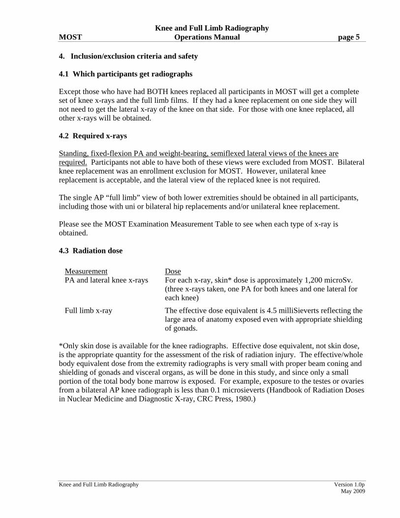
4. Inclusion/exclusion criteria and safety 4.1 Which participants get radiographs Except those who have had BOTH knees replaced all participants in MOST will get a complete set of knee x-rays and the full limb films. If they had a knee replacement on one side they will not need to get the lateral x-ray of the knee on that side. For those with one knee replaced, all other x-rays will be obtained. 4.2 Required x-rays Standing, fixed-flexion PA and weight-bearing, semiflexed lateral views of the knees are required. Participants not able to have both of these views were excluded from MOST. Bilateral knee replacement was an enrollment exclusion for MOST. However, unilateral knee replacement is acceptable, and the lateral view of the replaced knee is not required. The single AP “full limb” view of both lower extremities should be obtained in all participants, including those with uni or bilateral hip replacements and/or unilateral knee replacement. Please see the MOST Examination Measurement Table to see when each type of x-ray is obtained. 4.3 Radiation dose
Measurement Dose PA and lateral knee x-rays For each x-ray, skin* dose is approximately 1,200 microSv.
(three x-rays taken, one PA for both knees and one lateral for each knee)
Full limb x-ray The effective dose equivalent is 4.5 milliSieverts reflecting the large area of anatomy exposed even with appropriate shielding of gonads.
*Only skin dose is available for the knee radiographs. Effective dose equivalent, not skin dose, is the appropriate quantity for the assessment of the risk of radiation injury. The effective/whole body equivalent dose from the extremity radiographs is very small with proper beam coning and shielding of gonads and visceral organs, as will be done in this study, and since only a small portion of the total body bone marrow is exposed. For example, exposure to the testes or ovaries from a bilateral AP knee radiograph is less than 0.1 microsieverts (Handbook of Radiation Doses in Nuclear Medicine and Diagnostic X-ray, CRC Press, 1980.)

Knee and Full Limb Radiography MOST Operations Manual page 6
Knee and Full Limb Radiography Version 1.0p
May 2009
5. Training and certification 5.1 Training Separate on-site training of radiology technologists will take place at each site. During the first 3 months of the baseline visit all x-rays were sent to the Boston University Radiography Center weekly so that the quality of the films could be assessed. See section below regarding continuing certification of x-ray technologists. 5.2 Site and technologist certification a. Each x-ray facility should designate a primary contact/supervisor for this study. Generally,
this person should be the x-ray technologist’s supervisor, with responsibility for seeing that the MOST x-ray procedures are carried out correctly.
b. The primary contact should have a detailed knowledge of the MOST x-ray protocols. This person is responsible for assuring that:
• all x-ray technologists taking films in the study are certified on the MOST x-ray protocol and are assigned a MOST staff ID number.
• all MOST x-rays are taken according to the MOST protocol
• copies of the x-ray protocol are available to MOST x-ray technologists at all times. c. The primary contact should complete the MOST X-ray Facility Certification Form
(Appendix 1). The clinical center should send a copy of this form to the MOST Coordinating Center.
d. The primary contact/supervisor should assign specific technologists to this study. Each
technologist is given a MOST Staff ID number by clinical center.
• Two or three technologists are recommended
• Technologists assigned to MOST should be experienced in bone and joint radiography.
e. All assigned MOST technologists should read and have a thorough knowledge of the procedures outlined in the MOST protocol and review any questions with the primary contact. A MOST X-ray Technologist Identification Form, signed by each x-ray technologist and the primary contact/supervisor should be sent in to the Boston University Radiography Center (see Appendix 2).

Knee and Full Limb Radiography MOST Operations Manual page 7
Knee and Full Limb Radiography Version 1.0p
May 2009
f. Individual technologists will be certified by the BU Radiography Center based on review of their first 10 sets of radiographs. Note that each set of radiographs is one participant's radiographs.
g. Individual technologists will be recertified after an absence of no more than 3 months by the
BU Radiography Center based on review of 5 sets of radiographs. If the absence is more than 3 months, recertification will be based on review of 10 sets of radiographs. Again, note that each set of radiographs is one participant's radiographs.
6. Ongoing quality review at x-ray facility and BU Radiography Center 6.1 Facility a. The technologist must carefully review all films, using the QA checklist, while the
participant is still in the x-ray room so that, if necessary, a repeat film may be obtained without additional burden on the participant.
b. The primary contact at each facility should review all knee films for protocol adherence and
quality before they are sent. If the primary contact plans an absence or vacation, then they should work with the replacement for at least one full day in clinic to review and refamiliarize the replacement with the protocol.
c. In addition, “problem cases” where the technologist or supervisor is unsure of the quality of
the image should be identified for review at the Radiology Coordinating Center. This is recorded in the “comment” section on the Knee X-ray Transmission [Shipment at baseline through 30-month follow-up] Log (See Appendix 3).
6.2 BU Radiography Center a. The MOST Radiography Center at Boston University will review the quality of all films
during the study, and will assess the performance of each technologist. b. The technologist, supervisor, and the clinic coordinator will be notified of departures from
optimal imaging and examination technique so that corrections can be made. c. Repeat films will be requested for films that do not provide valid information. 7. Detailed knee imaging technique and examination procedure Participant preparation: All participants need to have knees visible for these x-rays. They can either wear shorts or sweat pants that can be pulled above the knees. X-rays will be done with shoes off.
Knee and Full Limb Radiography MOST Operations Manual page 8
Knee and Full Limb Radiography Version 1.0p
May 2009
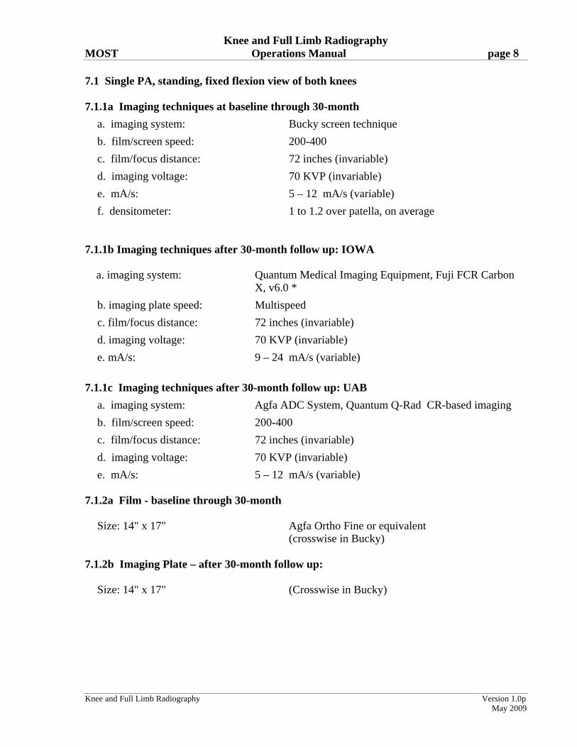
7.1 Single PA, standing, fixed flexion view of both knees 7.1.1a Imaging techniques at baseline through 30-month
a. imaging system: Bucky screen technique
b. film/screen speed: 200-400
c. film/focus distance: 72 inches (invariable)
d. imaging voltage: 70 KVP (invariable)
e. mA/s: 5 – 12 mA/s (variable)
f. densitometer: 1 to 1.2 over patella, on average 7.1.1b Imaging techniques after 30-month follow up: IOWA a. imaging system: Quantum Medical Imaging Equipment, Fuji FCR Carbon
X, v6.0 *
b. imaging plate speed: Multispeed
c. film/focus distance: 72 inches (invariable)
d. imaging voltage: 70 KVP (invariable)
e. mA/s: 9 – 24 mA/s (variable)
7.1.1c Imaging techniques after 30-month follow up: UAB
a. imaging system: Agfa ADC System, Quantum Q-Rad CR-based imaging
b. film/screen speed: 200-400
c. film/focus distance: 72 inches (invariable)
d. imaging voltage: 70 KVP (invariable)
e. mA/s: 5 – 12 mA/s (variable) 7.1.2a Film - baseline through 30-month Size: 14" x 17" Agfa Ortho Fine or equivalent (crosswise in Bucky) 7.1.2b Imaging Plate – after 30-month follow up: Size: 14" x 17" (Crosswise in Bucky)
Knee and Full Limb Radiography MOST Operations Manual page 9
Knee and Full Limb Radiography Version 1.0p
May 2009
7.1.3 Preparation a. Beam angle calibration. At the beginning of the study and at the beginning of each
subsequent month, the x-ray tube will be calibrated to ensure that a 5, 10 or 15 degree caudal (toward the feet) angle as indicated by the tube angle indicator is actually 5, 10 or 15 degrees. Use the inclinometer. First, angle the tube so that it is at 10 degrees caudal according to the dial. Next, place the inclinometer on the top of the x-ray tube. On the inclinometer, read off the actual degrees of this beam angle. If not 10 degrees caudal, adjust the beam angle so that the inclinometer reads 10 degrees. Mark where this is on the x-ray tube. This will be the ’10 degree’ beam angle that is used in the study. Next angle the tube to 15 degrees caudal, and use the inclinometer to check the actual angle. If not 15 degrees caudal, adjust the beam angle so that the inclinometer reads 15 degrees. Mark where this is on the x-ray tube angle indicator. Do the same procedure for a 5 degree beam angle. Record results on the beam angle calibration logs (Appendix 5).
b. The x-ray tube is positioned so that the central ray of the x-ray beam is angled at 10 degrees toward the feet (caudal).
c. You will also be occasionally repeating these x-rays at 5 degrees and 15 degrees. d. Beam angle check. After setting the beam angle using the marks on the x-ray tube dial, use
the level pitch and slope locator to confirm that the x-ray tube is angled correctly before taking each film.
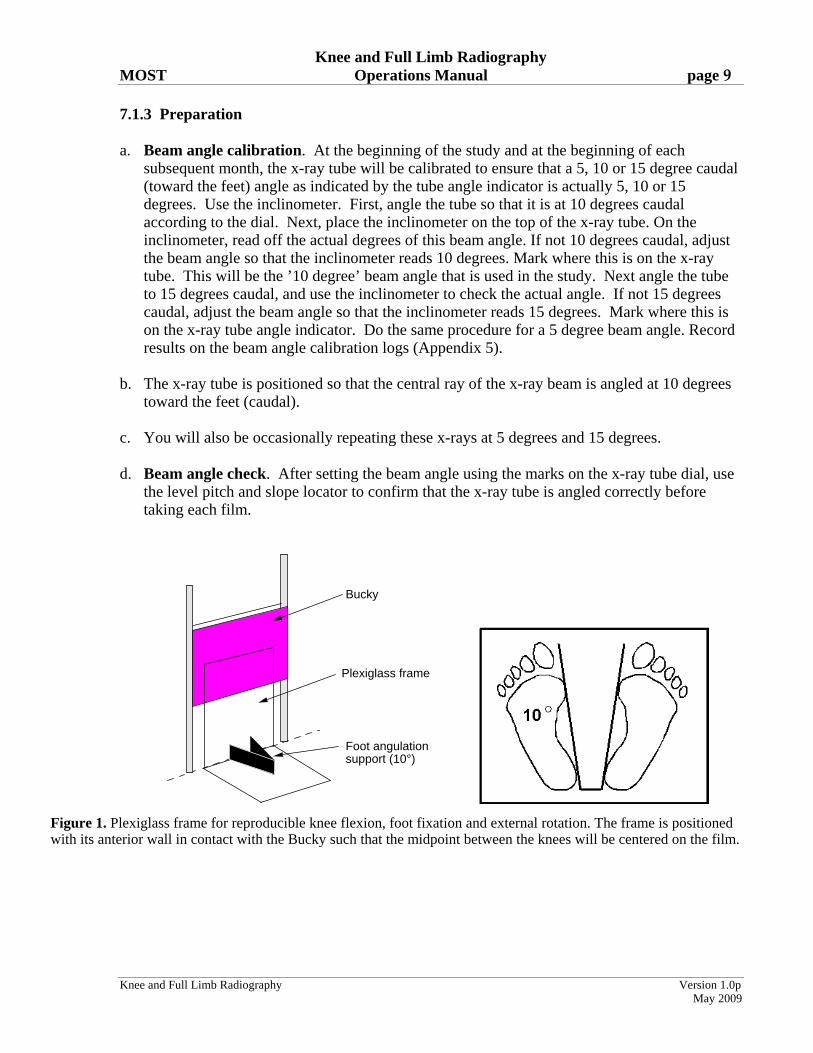
Bucky
Plexiglass frame
Foot angulation support (10°)
Figure 1. Plexiglass frame for reproducible knee flexion, foot fixation and external rotation. The frame is positioned with its anterior wall in contact with the Bucky such that the midpoint between the knees will be centered on the film.
Knee and Full Limb Radiography MOST Operations Manual page 10
Knee and Full Limb Radiography Version 1.0p
May 2009
e. The anterior wall of the plexiglass frame is in contact with the Bucky tray (Figure 1). The plexiglass frame is positioned on the floor with the foot angulation support centered to the middle (left/right) of the Bucky tray. This will center the midpoint of the x-ray beam between the knees over the Bucky and the film for most participants. Lower the Bucky so that the center of the film is at the level of the tibiofemoral joint line.
f. Tape a quarter (25¢ piece) to the side of the plexiglass frame that goes up against the bucky. The position of the coin should be 18 inches from the bottom of the frame (where the frame meets the floor) to the bottom of the coin. This placement is done to assess magnification and to enable a double check of the side markers. Note: This position should ensure that the coin does not block a view of the medial side of the PA but for very tall participants please double check.
g. Identify the position of the tibiofemoral joint space by locating the inferior border of the patella and the superior margin of the tibial tuberosity; trace this line around to the side of the knee and mark the skin with a felt tip pen. This mark will be used to help align the center of the x-ray beam with the joint space (see section 7.1, 6b. below).
7.1.4 Participant position Both knees are x-rayed together
a. The participant should be without shoes.
b. The participant stands with both knees facing the film cassette in an erect Bucky or film holder, with a film to focus distance (FFD) of 72 in.
c. Body weight is distributed equally between the two legs, and the great toes of both feet are placed in contact with the front plate of the plexiglass frame. IMPORTANT: The inner aspects and heels of both feet should be in contact with foot angulation support so that the foot position can be reproduced exactly on follow-up films.
d. The knees and thighs are pressed directly against the front plate of the frame and Bucky to fix the degree of knee flexion. IMPORTANT: the knees and front of the thighs must be in contact with the front plate of the frame so that knee flexion can be reproduced exactly on the follow-up film. First ask participant to touch knees to the frame; then ask them to lean forward so that the front of their thighs also touch the frame. (In this position the tibial plateau will be at, or near, a 10 degree angle (caudad) to the film.) The participant should hold onto the Bucky tray frame for support.
Suggested script: “Touch your toes to the front plate of the plexiglass frame. Now press your knees into the front of the frame and then lean forward so that the front of your thighs are pressing firmly into the frame. Great. Now, make sure the insides of your feet and heel are snug up against the foot plates.”
e. The external rotation of the feet is fixed at about 10 degrees by the frame. (Figure 2).
Knee and Full Limb Radiography MOST Operations Manual page 11
Knee and Full Limb Radiography Version 1.0p
May 2009
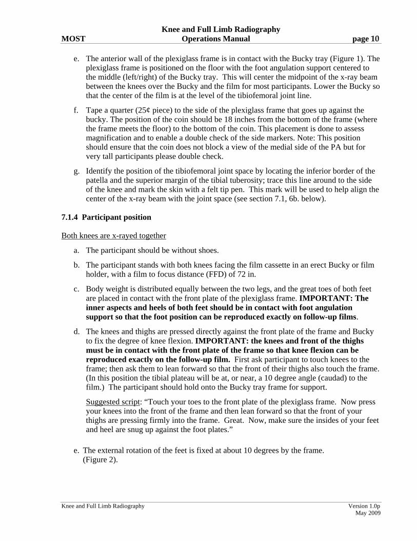
10°
Foot angulation and fixation frame
Figure 2. Proper patient positioning and beam angulation for radiography of the knee. Pressing the thigh against the Bucky fixes the degree of flexion of the femur. Reproducible positioning of the foot in 10 degree angulation is accomplished using a V-shaped support on a plexiglass frame.
f. The participant’s gonads are shielded with a half apron. 7.1.5 Knee position
a. Both knees are imaged at the same time in a posteroanterior (PA) view. Important: For participants with asymmetric “bow legs,” it may be necessary to position the frame slightly to one side so that the midpoint between the knees is centered on the film.
b. Place a right marker on the right edge of the cassette.
c. The film marker block (ID stamp) must be in same place each time (top or bottom of film direction, always to the right).
7.1.6 Central ray
a. The tube is positioned so that the x-ray beam is directed at the midpoint between the back of the knees.
b. The tube’s positioning light is used to align the center of the x-ray beam midway between the knees and in the same horizontal plane as the center of the joints, defined by the marking of the joint space (see Section 7.1.3, e. above), and which lies above the horizontal skin crease of the popliteal fossa.
c. Baseline through 30-month: The radiograph is taken immediately once this position is obtained. Follow-up: The tube is positioned so that the x-ray beam angle is the same as the best beam angle(s) used in the past. See Data from Prior Visits report for beam angle(s).
Knee and Full Limb Radiography MOST Operations Manual page 12
Knee and Full Limb Radiography Version 1.0p
May 2009
d. Follow-up: The radiograph is taken immediately once this position is obtained.
e. The beam angle(s) should be marked on the radiograph. Lead marker is used for hard copies (baseline through 30-month).
7.1.7 Participant instruction
Have the participant understand the importance of holding still.
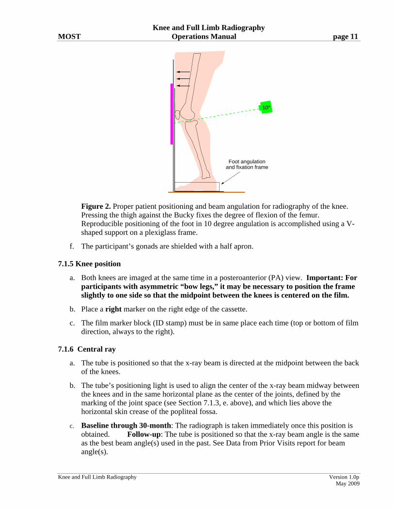
Suggested script: “Please stand still so that the image will be clear.” 7.1.8 Criteria for assessing image quality See Figure 3 for anatomic drawing of acceptable and unacceptable films. Superposition of the posterior and anterior edges of the tibial plateau is required to accurately demonstrate the joint space.
a. If the edge of the tibial plateau nearly touches or overlaps the distal femoral condyle on either knee (see Figure 3 below for unacceptable), repeat the x-ray at a beam angled at 5 degrees and then at 15 degrees, and record this on the form.
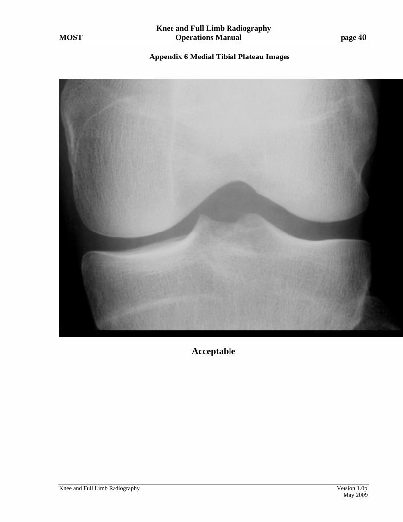
b. Correct contrast/exposure: be able to see soft tissue; and medial and lateral sides of the knee joint including all bones without use of a bright light. See Figure 3b and Appendix 6.
c. Exposure settings should be set to provide optimal visualization of the articular surfaces. The floor of the medial tibial plateau should be clearly delineated.
d. The knees should be centered on the film.
Figure 3a

Knee and Full Limb Radiography MOST Operations Manual page 13
Knee and Full Limb Radiography Version 1.0p
May 2009
Good
Unacceptable
Figure 3b
Note: Figure 3a and Figure 3b should be used together to decide whether to repeat the PA view at different angles. These decisions are based on imaging of the joint space in the medial tibiofemoral compartment, specifically whether the tibial plateau's anterior and posterior margins overlap. When they overlap perfectly and the joint is seen straight through (figure 3a ideal), they should not be repeated. Even if the anterior and posterior lips of the medial tibia are a short distance from one another and there is considerable space between the femur and the tibia (Figure 3a, acceptable), the films do NOT need to be repeated. . When the tibial plateaus don't overlap completely and the tibia is either very close to (figure 3b unacceptable) or overlapping with (figure 3a non-acceptable) the femur, these films need to be repeated.
7.1.9 Record the mA/s and beam angle(s) used on the data collection form. 7.2 Weight-bearing, lateral, semi-flexed view of each knee 7.2.1a Imaging techniques - baseline through 30-month
a. imaging system: Bucky screen technique
b. film/screen speed: 400
c. film/focus distance: 72 inches (invariable)
d. imaging voltage: 65-70 kVp (invariable)
e. mA/s: 7 – 13 mA/s (variable)
f. densitometer: 1 to 1.2
Knee and Full Limb Radiography MOST Operations Manual page 14
Knee and Full Limb Radiography Version 1.0p
May 2009
7.2.1b Imaging techniques after 30-month follow up: Iowa
a. imaging system: Quantum Medical Imaging Equipment, Fuji FCR Carbon X, v6.0*
b. imaging plate speed: Multispeed
c. film/focus distance: 72 inches (invariable)
d. imaging voltage: 65-70 kVp (invariable)
e. mA/s: 9 – 19 mA/s (variable)
7.2.1c Imaging techniques after 30-month follow up: UAB
a. imaging system: Agfa ADC System, Quantum Q-Rad CR-based
b. film/screen speed: 400
c. film/focus distance: 72 inches (invariable)
d. imaging voltage: 65-70 kVp (invariable)
e. mA/s: 7 – 13 mA/s (variable)
7.2.2 Film/cassette size: 14" x 17” cassette 7.2.3 Preparation
a. Participant is still wearing the lead apron.
b. Participant should not be wearing shoes.
c. For the right lateral knee x-ray, the plexiglass frame is positioned so that the large vertical front plate of plexiglass is perpendicular to the Bucky. This vertical front plate should meet the Bucky approximately 2 inches to the left of the middle of the Bucky. (If using the PA plexiglass frame, the foot plate and foot fixation device should be positioned so they are on the opposite side of the front plate from where the participant will stand.)
d. For the second lateral film, which will be of the left knee, turn the plexiglass frame 180 degrees from its position for the right knee. The vertical plate should meet the Bucky approximately 2 inches to the right of the middle of the Bucky. (If using the PA plexiglass frame, the foot plate and foot fixation device should be positioned so they are on the opposite side of the front plate from where the participant will stand.)
Knee and Full Limb Radiography MOST Operations Manual page 15
Knee and Full Limb Radiography Version 1.0p
May 2009
7.2.4 Participant position Each knee is x-rayed separately. RIGHT KNEE
a. The participant should turn so that their right side is parallel to the Bucky with their right leg against the Bucky. The tip of the right foot should contact the vertical plexiglass sheet.
b. Participant should bend their right knee so that it also contacts the vertical plexiglass sheet.
c. The left foot is positioned such that the tip of this foot is placed just behind the right heel. For the participant to be comfortable, the left foot does not have to be directly behind the right foot, but can be over to the side. This should produce 40-50 degrees of flexion of the RIGHT knee.
d. Once the left foot is placed, the participant should lock the left knee in full extension.
LEFT KNEE
e. The participant should turn so that their left side is parallel to the Bucky with their left leg against the Bucky. The tip of the left foot should contact the vertical plexiglass sheet. The left foot should be pointed so that it is parallel to the Bucky and should be positioned so that the left leg and knee are contacting the Bucky.
f. Participant should bend their left knee so that it also contacts the vertical plexiglass sheet.
g. The right foot is positioned such that the tip of this foot is placed just behind the left heel. For the participant to be comfortable, the right foot does not have to be directly behind the left foot, but can be over to the side. Once the foot is placed, the participant should lock the right knee in full extension.
h. Provide object (such as an IV pole without wheels) for participant to hold onto for support, if necessary.
i. Lateral knee films are weight bearing films, with weight distributed evenly between the front and back limbs.
Knee and Full Limb Radiography MOST Operations Manual page 16
Knee and Full Limb Radiography Version 1.0p
May 2009
7.2.5 Knee position
a. Center the knee to the film.
b. Place a right or left marker on each film.
c. The film marker block (ID stamp) must be in same place each time (always at the bottom where the ID number will be).
d. Once the film is developed, participant ID will be on the top right. For right laterals, this will be BEHIND the knee (whereas for left laterals [below], the participant ID will be IN FRONT OF the knee).
7.2.6 Central ray
a. Direct the central ray perpendicular to the knee. Tube is at 0 degrees, DO NOT ANGLE THE TUBE.
b. Center the beam to the flexed (forward) knee joint at the joint line, as indicated in Section 7.1.3.e, above.
c. Use collimation to reduce scatter radiation. Collimate only the horizontal dimension - leave vertical open at maximum.
7.2.7 Participant instruction
a. Weight should be distributed evenly between limbs. Have the participant understand the importance of holding still.
7.2.8 Criteria for assessing image quality
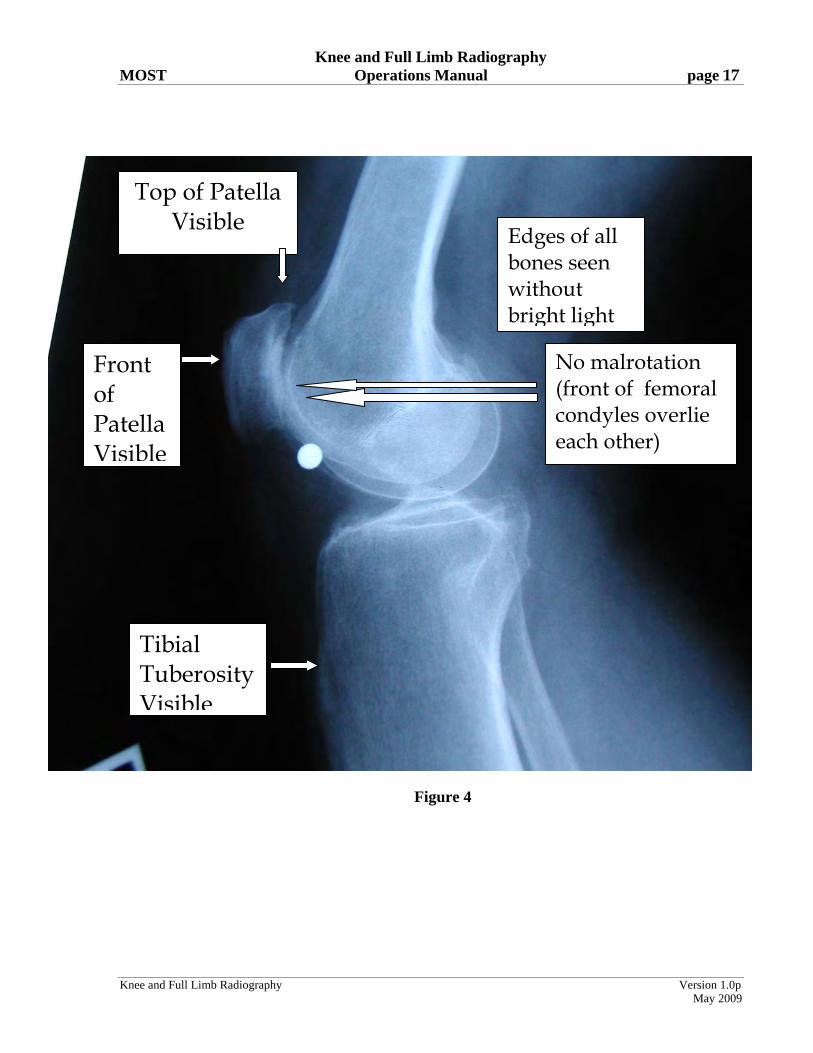
a. For these x-rays to be acceptable, all of the following structures need to be fully visualized. Figure 4 below is acceptable:
i. tibial tubercle (where patellar tendon inserts)
ii. upper border of patella
iii. front of patella
iv. upper end of fibula
b. If positioning is correct, (see Figure 4) the contours of the front edge of the medial and lateral femoral condyles should nearly overlie one another or be superimposed.
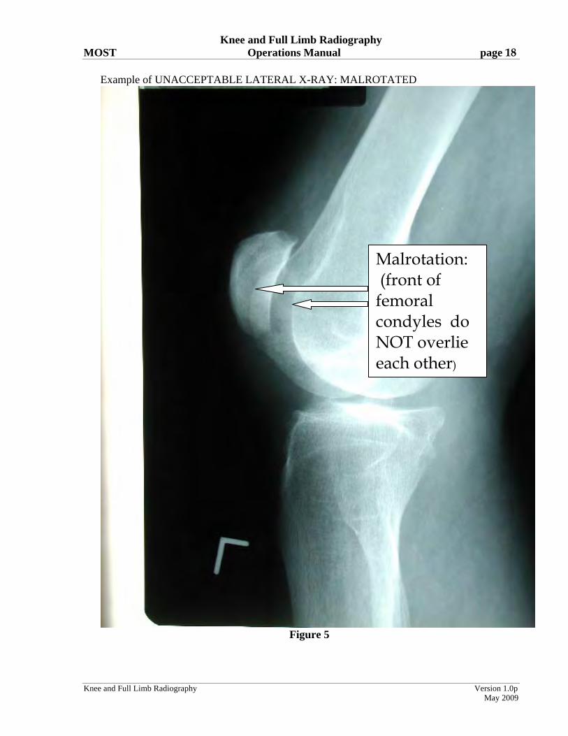
c. Film cannot be excessively rotated. Figure 5 shows an excessively rotated lateral view, in
which the contours of the front edges of the femoral condyles do not overlie one another and are instead separated by 1 cm or more.
Knee and Full Limb Radiography MOST Operations Manual page 17
Knee and Full Limb Radiography Version 1.0p
May 2009
Figure 4
Top of Patella Visible
Tibial Tuberosity Visible
Front of Patella Visible
Edges of all bones seen without bright light
No malrotation (front of femoral condyles overlie each other)
Knee and Full Limb Radiography MOST Operations Manual page 18
Knee and Full Limb Radiography Version 1.0p
May 2009
Example of UNACCEPTABLE LATERAL X-RAY: MALROTATED
Figure 5
Malrotation: (front of femoral condyles do NOT overlie each other)

Knee and Full Limb Radiography MOST Operations Manual page 19
Knee and Full Limb Radiography Version 1.0p
May 2009
IMPORTANT: It is the responsibility of the clinical center to verify the legibility, completeness and accuracy of all identifying information on the x-ray label before the x-ray is transmitted to the Radiology Coordinating Center. [Baseline through 30-month: Missing or illegible information should be typed on a separate stick-on label, and placed next to (NOT OVER) the ID stamp. The x-ray tech ID may also be recorded on a stick-on label.]
7.3 Single AP, full limb view of both lower extremities - after 30-month follow up With this view, we will image both entire lower extremities (including a full view of the anterior superior iliac crest and the ankle talus) at the same time, in a weight-bearing position. The goal of this is to measure knee alignment, defined here as the angle made by lines drawn from the femoral head to the knee and from the knee to the ankle surface, using specific femoral head, knee, and ankle landmarks. Alignment can be characterized as neutral (hip/knee/ankle angle is 0 degrees or a straight line), varus (alignment is > 0 degrees in the direction of a bow-legged appearance), or valgus (alignment is > 0 degrees in the direction of a knock-knee appearance). (Please see Figures 6-7.). Additional goals at this visit are to use this film to get a measurement of the Q angle, an angle formed by the line of the quads muscles in the thigh and the patellar tendon from the patella to the tibial tubercle. To assess the Q angle, we will need to make sure we know on the image where the anterior superior iliac crest is (the front brim of the pelvis), the patella and the tibial tubercle.
Knee and Full Limb Radiography MOST Operations Manual page 20
Knee and Full Limb Radiography Version 1.0p
May 2009
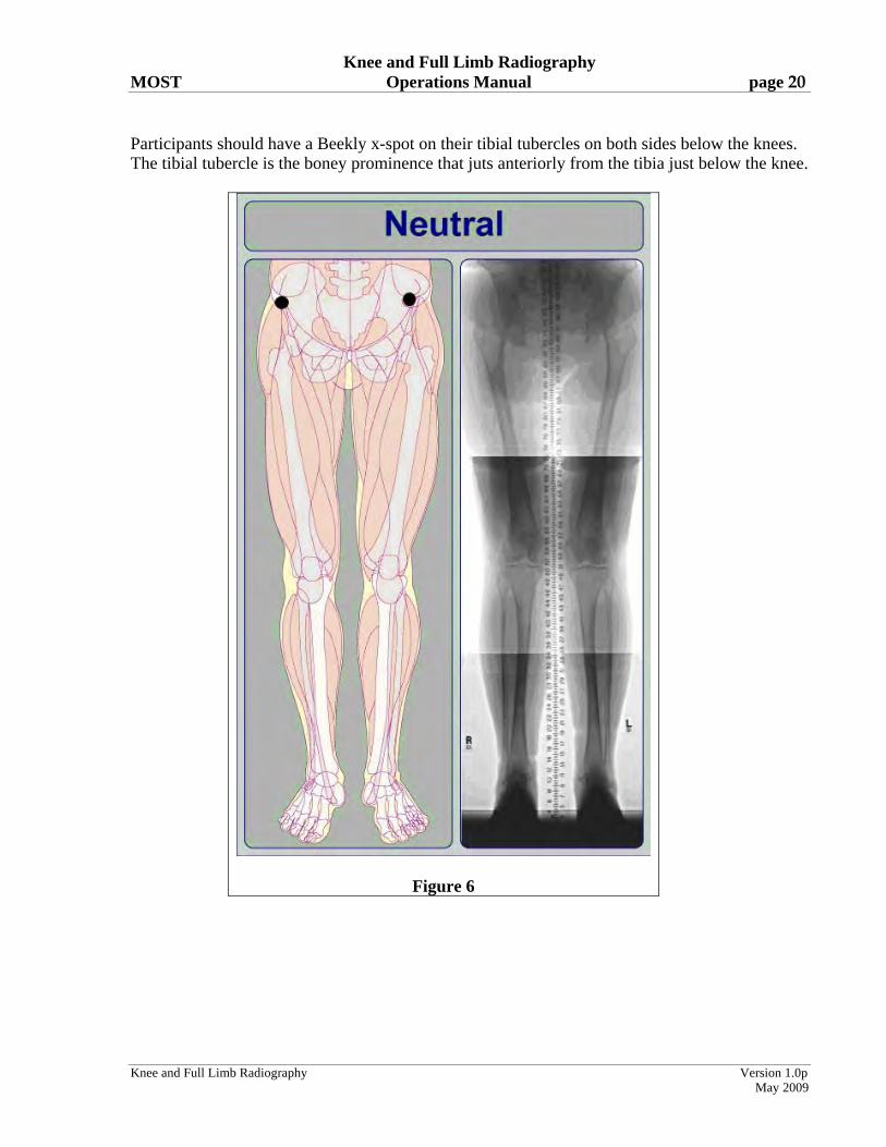
Participants should have a Beekly x-spot on their tibial tubercles on both sides below the knees. The tibial tubercle is the boney prominence that juts anteriorly from the tibia just below the knee.
Figure 6

Knee and Full Limb Radiography MOST Operations Manual page 21
Knee and Full Limb Radiography Version 1.0p
May 2009
Figure 7
7.3.1.1 Imaging techniques: IOWA a. Imaging system: Quantum Medical Imaging Equipment, Fuji FCR Carbon
X, v6.0 * b. Film/screen speed: CR Imaging is a multispeed system c. Film/focus distance: 80 inches. If the anterior superior iliac crest is not
visualized at 80 (unlikely but possible in long-legged individuals), increase the film/focus distance to include the anterior superior iliac crest.
d. Imaging voltage 80-90 kVp e. mA/s: 50-300
Knee and Full Limb Radiography MOST Operations Manual page 22
Knee and Full Limb Radiography Version 1.0p
May 2009
* With the Fuji CR system for full-limb imaging there is a triple cassette used. There is a vertical wall Bucky with a grid attached to the front. The triple cassette is slid in the Bucky behind the grid. Once the triple cassette is exposed, it is separated into two cassettes and processed in the Carbon X. We then do the stitching process and send the images. 7.3.1.2 Imaging techniques: UAB a. Imaging system: Agfa ADC System, Quantum Q-Rad CR-based imaging technique.* b. Film/screen speed: 400 speed (upper section) 200 speed (lower two sections) c. Film/focus distance: 80 inches. If the anterior superior iliac crest is not
visualized at 80 (unlikely but possible in long-legged individuals), increase the film/focus distance to include the anterior superior iliac crest.
d. Imaging voltage 80-90 kVp e. mA/s: 100-300 * The Agfa CR approach for full-limb includes a stack of cassettes, each holding an imaging plate. A standard wall Bucky is equipped with a rigid support, mounted in the vertical position to the Bucky. For the full-limb x-ray, there are three cassettes inserted in the support, such that each cassette overlaps with its preceding and succeeding cassettes. The front panel at the tube side of the support holds the rectangular grid that is utilized in the stitching process. 7.3.2 Participant position a. Participant will stand on the step-stool (necessary to ensure that the ankle is included). b. Participant should be standing without shoes, with their back to the wall Bucky that holds the
three cassettes. Both tibial tubercles should be facing directly forward. (the x-spots should be placed on these tubercles). Feet should be 6 inches apart. Two permanent marks will be made on the step stool that are 6 inches apart. The tips of the big toes should be positioned at these marks.
c. Participant should be instructed to bear weight equally on both limbs. Suggested script: Please stand so that your weight is the same on your right leg and left leg.” d. Participant’s gonads should be shielded with a gonad shield that will be folded (folding held
by velcro) differently for men and women to shield gonads without obscuring hip joint.
Knee and Full Limb Radiography MOST Operations Manual page 23
Knee and Full Limb Radiography Version 1.0p
May 2009
e. Participant will hold onto hand rails for support, if necessary. f. The participant’s body should be parallel to the grid plane. The participant-grid plane
distance should be kept as small as possible. 7.3.3 Limb position a. Both lower limbs are imaged at the same time in an AP view. b. Center the knees to the film (in participants above 6 feet in height, center at the top of the
patella). c. The anterior superior iliac crest, the hip joint, the knee joint, the tibial tubercle, and the tibio-talar (ankle) joint must be included in the image. NOTE: The tibial spines of both knees must be fully visible on the image. If this seems unlikely due to varus deformity, do a separate full limb of each leg, following the same protocol but repeating it for each limb separately. If the participant is too tall for the ankle joint and the anterior superior iliac crest to fit on the long limb image, first, try to make it fit. If it can’t, the priority is to get hip, knee and ankle on the film. You can avoid the anterior superior iliac crest in that circumstance. d. Place a right or left marker on each film e. The film marker block (ID stamp) must be in same place each time f. A radiopaque ruler will also be imaged to provide a method to check the electronic stitching
of the images. 7.3.4 Central ray a. Direct the central ray perpendicular to the knee. Tube is at 0 degrees. DO NOT ANGLE
THE TUBE. b. Center of the x-ray beam should be directed midway between the two knees at the level of
the joint spaces. Identify the position of the tibiofemoral joint space by locating the inferior border of the patella and the superior margin of the tibial tuberosity. Trace this line around to the side of the knee and mark the skin with a felt tip pen. This mark will be used to help align the center of the x-ray beam with the joint space (see section 7.1.3.e above).
7.3.5 Participant instruction Have the participant understand the importance of holding still.

Knee and Full Limb Radiography MOST Operations Manual page 24
Knee and Full Limb Radiography Version 1.0p
May 2009
Suggested script: “Please do not move at all so that the image will be clear.” 7.3.6.1 Electronic stitching: IOWA a. Cassettes are exposed and placed into the image reader. While in the image reader, the image
plate is read, erased, and then restored in the cassette for re-use. The image that is read is now on the work station and can be manipulated.
b. CR technology creates one combined image from a series of overlapping sub images (which
have been exposed simultaneously). A digital image-processing algorithm assembles the stitched image. Creating the stitched image:
1) Once you have achieved optimal density and contrast on the image, you want to exit the QA screen by selecting the terminate QA icon.
2) Select one of the images to be stitched (where the words are and not the picture)
3) Select the image stitching icon. 4) The preview dialog box is displayed. As long as the image is correct, select
OK. The stitched image is displayed.
c. The stitched image is ready to be transferred to BU. The images that are transferred include the stitched image along with the three separate images (pelvis, knee and ankle).
7.3.6.2 Electronic stitching: UAB a. Cassettes are removed and placed into the digitizer. While in the digitizer, the laser plate is
read, erased, and then restored to the cassette for re-use. The digitized image is now on the work station and can be manipulated.
b. CR technology forms a total body part image from a series of overlapping subimages (which
have been exposed simultaneously). During exposure, a rectangular grid of lines is present in the x-ray path to aid in the stitching process. A digital image-processing algorithm assembles a composite or “stitched” image.
Creating the stitched image:
1. On the browser screen, user selects all subimages that will make up the composite image, starting with the bottom-most image.
2. Highlight selected images. 3. Select “full-leg/full-spine” option which causes a screen to appear to
display the subimages. 4. Rotate the subimages to bring them into the upright position. 5. Press “stitch” to created composite image.
c. The stitched image should be:
1) archived at the site and 2) sent to reading center at BU

Knee and Full Limb Radiography MOST Operations Manual page 25
Knee and Full Limb Radiography Version 1.0p
May 2009
7.3.7 On-site quality assurance At the work station, after stitching and while the participant is still present in the x-ray suite, the following should be checked by the technician. If the film does not demonstrate good quality in the following points, it should be repeated. Important points to watch out for include hips and pelvis that are underpenetrated (too light and washed out) and limbs that are so varus (bow-legged) that one or both knees are left off the image.
a. anatomical coverage 1) The anterior superior iliac crest, hip joint, knee joint, and tibio-talar joint must
be included and clearly visible in the image. The image should extend far enough superiorly to capture the anterior superior iliac crest
2) The patella and tibial spines must be completely visualized. If not, repeat, doing a separate full limb film of each leg.
3) The tibial tubercles of both sides must be seen as marked by the x-spot.
b. proper centering on the film
c. delineation of anterior superior iliac crest, hip, knee, and ankle joint spaces. The hip joint and pelvis should be clearly visible (not washed out or underpenetrated), from the lateral edge of the acetabulum the film should go high enough to see the anterior superior iliac crest. Use the abdominal binder, if necessary in participants with sagging abdominal fat, to improve penetration at the hips, to better visualize the hip joint space (see Appendix 7).
d. clear delineation of planned measurement landmarks (anterior superior iliac crest, center of femoral head, patella, tibial spines, tibial tubercles and center of talar surface). The stitching should not cover any of these essential landmarks.
e. proper exposure at proximal and distal extremes of the image f. no evidence of patient motion g. check for line-up of radiopaque ruler. This should be right after the image is “stitched,”
i.e., on the workstation image. 7.3.8 Record the mA/s used on the tracking form

Knee and Full Limb Radiography MOST Operations Manual page 26
Knee and Full Limb Radiography Version 1.0p
May 2009
1 inch above the anterior superior iliac crest
the hip joint
knee joint and patella
tibial tubercle
and
tibio-talar joint
must be included and clearly visible in the image.
Figure 8 8. Radiograph labeling
a. The x-ray films should include the following information on the ID stamp/Dicom header:
1. Clinic site (Iowa, UAB) and/or x-ray facility name 2. MOST ID and acrostic 3. Date of x-ray 4. X-ray tech ID or instead may be stamped on the x-ray with a lead marker 5. X-ray view, e.g. Bilateral PA knees, Right Lateral knee, etc 6. Beam angle for PA films (can be combined with x-ray view, e.g., 10 degree Bilateral PA knees
Knee and Full Limb Radiography MOST Operations Manual page 27
Knee and Full Limb Radiography Version 1.0p
May 2009
b. Be sure the ID stamp is on the right side (if possible) and that each film has a left/right marker that is clearly visible.
c. The x-ray image, ID stamp, or header cannot contain any of the following:
- Name or acrostic based on the name - Birthdate - Medicare or SS# - Medical record number
Baseline through 30-month: To ensure legibility, all label information should be typed whenever possible.
IMPORTANT: It is the responsibility of the clinical center to verify the legibility, completeness and accuracy of all identifying information on the x-ray label before the x-ray is shipped to the Radiology Coordinating Center. Missing or illegible information should be typed on a separate stick-on label, and placed next to (NOT OVER) the ID stamp. The x-ray tech ID may also be recorded on a stick-on label. In general, additional stick-on labels with redundant information (e.g., film date) are unnecessary and are discouraged. Any stick-on labels used should be placed next to (but not over) the imaged ID stamp. Follow-up: To have consistency with how earlier x-rays were labeled, it is necessary to use the following labels on the dicom header to acquire x-rays that can be viewed and read longitudinally in an easy, standardized fashion.
8.1.1. Dicom header (after 30-month): Iowa Imaging system: Quantum Medical Imaging Equipment, Fuji FCR Carbon X, v6.0
Patient’s Name: MOSTID ACROSTIC Patient ID: # VISIT Series Description: Name of X-ray, e.g. 10 degree PA, Left Lateral, Right Lateral, etc 8.1.2. Dicom header (after 30-month): UAB
Imaging system: Agfa ADC System, Quantum Q-Rad CR-based imaging technique Last name: MOSTID^ACROSTIC Patient Identification: # VISIT Series Description: Name of X-ray, e.g. 10 degree PA, Left Lateral, Right Lateral, etc
IMPORTANT: It is the responsibility of the clinical center to verify the legibility, completeness and accuracy of all identifying information on the x-ray label before the x-ray is transmitted to the Radiology Coordinating Center.
Knee and Full Limb Radiography MOST Operations Manual page 28
Knee and Full Limb Radiography Version 1.0p
May 2009
9. Knee X-ray data collection form and X-ray Transmission [Shipment / Baseline through 30-month] Log Fill out the Knee X-ray data collection form for each MOST participant. First confirm that this is the correct participant. Ask their name, confirm in the chart that the name matches the MOST ID# and acrostic at the top of the form. Indicate on the form whether or not the x-rays were taken, the date of the x-rays, the staff ID# of the x-ray technician, and for each view (PA semiflexed view of right and left knee, lateral view of right knee, lateral view of left knee, and full limb view) indicate whether or not the x-ray was taken, the beam angle of the PA x-ray and what the mAs setting was. As each participant’s knee films are completed, fill in the information requested on the Knee X-ray Transmission [Shipment] Log (Appendix 3). In the comments section of the X-ray Transmission [Shipment] Log, fill in when the abdominal binder and / or filter was used and also if you judge that the participants was obese plus any other relevant comments. This helps when images are borderline or unacceptable and the reading center has to decide to ask for a participant to be called back for a repeat x-ray. The original of this log should be kept at the clinic. 10. Transmitting [Packaging, shipping/baseline through 30-month] x-ray films
10.1 Transmission of x-ray films: UAB
a. Each participant’s set of knee films should be sent to the backup server at the IT department at UAB; Iowa will not archive participant’s knee films. Both clinical sites will transmit each participant’s set of knee films to the Radiology Reading Center at Boston University and include:
Clinic site (and/or x-ray facility name MOST ID and acrostic Visit, e.g. 4th MOST X-ray view Date of x-ray
b. The films will be transmitted to the Reading Center via a Virtual Privacy Network (VPN)
tunnel, on a daily basis or, if this is not possible, at the latest by Tuesday of the following week. Please e-mail the Reading Center prior to the transmissions to let them know if transmissions are delayed.
c. Please email using Voltage SecureMail or fax a copy of the X-ray Transmission Log to
the Reading Center (email: [email protected] fax: 617-638-5239) daily.
d. Receipt of the images will be verified by the Reading Center by secure email.
Knee and Full Limb Radiography MOST Operations Manual page 29
Knee and Full Limb Radiography Version 1.0p
May 2009
10.2 Shipping of x-ray films from U of I - baseline through 30-month: a. Each participant’s set of knee films should be placed in a paper jacket labeled with: • Clinic site (Iowa) and x-ray facility name • MOST ID and acrostic • Date of x-ray
b. Films will be inventoried, boxed, and shipped by staff at the MOST clinical center.
c. A sturdy shipping container or other packaging should be used for each batch of x-rays
shipped (i.e., x-rays and CDs should be double wrapped).
d. Package a copy of the MOST Knee X-ray Shipment Log with the shipment. The log will be checked against the films contained in the shipment at the Radiography Center. Keep a copy of the X-ray Shipment Log at the MOST clinical center. Please e-mail ([email protected]) or fax (617-638-5239) a copy of X-ray Shipment Log to Boston University so they know about the shipment.
e. E-mail ([email protected]) or fax a copy of the X-ray Shipment Notification Form to the
Radiology Coordinating Center when the shipment is sent (Appendix 4). The bottom section of the form will be completed by the Reading Center and returned via e-mail or fax once the shipment is received.
Fax to:
MOST STUDY X-RAYS C/O Dr. David Felson (fax: 617-638-5239).
f. Send all films to:
MOST Study X-rays C/O Dr. David Felson
Clinical Epidemiology Research and Training Unit 715 Albany Street, A203
Boston, MA 02118
g. For security and speed of delivery, use of second day courier service (e.g., UPS second day air) is recommended.
h. Accumulated films should be shipped every two weeks (except for the first four
months of Visit 1 when they should be shipped every week). This schedule may be adjusted in the future.
Knee and Full Limb Radiography MOST Operations Manual page 30
Knee and Full Limb Radiography Version 1.0p
May 2009
11. Readings, results, and incidental findings The films will be checked for quality at the MOST reading center. If repeat films need to be taken, the reading center will contact the radiology staff at the clinical sites. The clinic coordinator at each site will also be notified, via e-mail, about the need for repeat films (see Appendix 8 for Quality Control Categories, and Appendix 9 for Repeat Knee X-ray data collection form). This information will be kept in a database and reports will be sent back to the Coordinating Center weekly (for the first 4 weeks), then every 2 weeks after that. At selected visits a preliminary reading of the radiographs will be done to inform the clinical sites about participant results so that a report can be sent to the participant (see Appendix 4). The participant report is read off the PA view and will be delayed appearing on the MOST website if a participant needs a repeat PA, if there are labeling issues on electronic images (as these need to be resent to the Reading Center corrected), or if there are queries as to whether the participant has osteoarthritis. Incidental findings:
Note that if the sites identify images where there are 'spots' or other incidental findings on a participant's x-ray that they should attach a note to the x-ray or note this on the X-ray Transmission [Shipment] Log. These 'spots' or incidental findings may also be noticed by the Reading Center. At the Reading Center these findings will be viewed by a rheumatologist and feedback from them will be e-mailed to the coordinator at the site, or, if it is decided that the finding needs to be checked by a radiologist or the participant's primary care provider, a letter regarding that finding will be sent to the PI at the site with copies to the Coordinating Center and the site coordinator.

Knee and Full Limb Radiography MOST Operations Manual page 31
Knee and Full Limb Radiography Version 1.0p
May 2009
12a. Knee X-ray Form - Baseline

Knee and Full Limb Radiography MOST Operations Manual page 32
Knee and Full Limb Radiography Version 1.0p
May 2009
12b. Knee X-ray Form – Follow-up

Knee and Full Limb Radiography MOST Operations Manual page 33
Knee and Full Limb Radiography Version 1.0p
May 2009
Appendix 1 MOST X-ray Facility Certification Form
Technicians have received comprehensive training in MOST x-ray imaging protocols
Only certified technicians do imaging
Imaging parameters specified in protocol are used exclusively
Films are repeated if they do not meet specified QA criteria Technologist Supervisors statement: Only identified technologists will be involved in this study. If personnel need to be added, they should be identified to the clinic and Coordinating Center. Clinical center X-ray facility location Last name, first name Position Address Phone number Signature Date
Knee and Full Limb Radiography MOST Operations Manual page 34
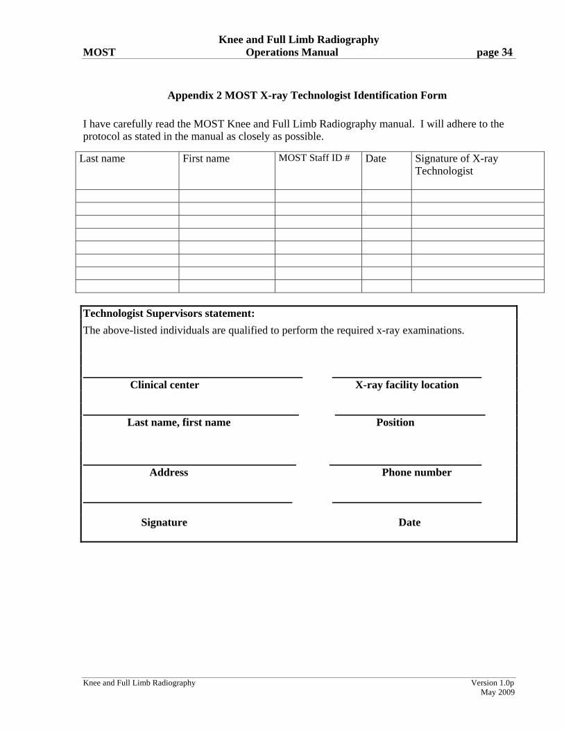
Appendix 2 MOST X-ray Technologist Identification Form
I have carefully read the MOST Knee and Full Limb Radiography manual. I will adhere to the protocol as stated in the manual as closely as possible.
Last name
First name
MOST Staff ID #
Date
Signature of X-ray Technologist
Technologist Supervisors statement:
The above-listed individuals are qualified to perform the required x-ray examinations.
Clinical center X-ray facility location Last name, first name Position Address Phone number Signature Date
Knee and Full Limb Radiography Version 1.0p
May 2009
Knee and Full Limb Radiography MOST Operations Manual page 35
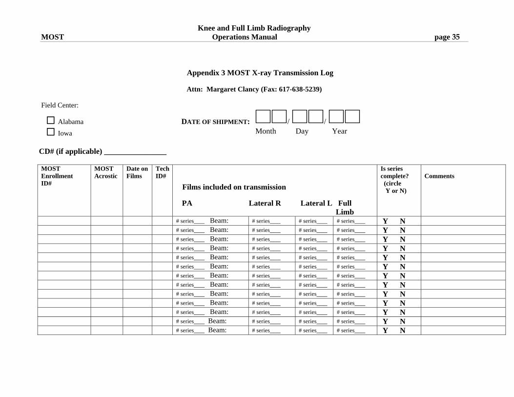
Appendix 3 MOST X-ray Transmission Log
Attn: Margaret Clancy (Fax: 617-638-5239)
Field Center:
Alabama DATE OF SHIPMENT: / /
Iowa Month Day Year
CD# (if applicable) ________________
Knee and Full Limb Radiography Version 1.0p
May 2009
MOST Enrollment ID#
MOST Acrostic
Date on Films
TechID#
Films included on transmission
PA Lateral R Lateral L Full Limb
Is series complete? (circle Y or N)
Comments
# series___ Beam: # series___ # series___ # series___ Y N # series___ Beam: # series___ # series___ # series___ Y N # series___ Beam: # series___ # series___ # series___ Y N # series___ Beam: # series___ # series___ # series___ Y N # series___ Beam: # series___ # series___ # series___ Y N # series___ Beam: # series___ # series___ # series___ Y N # series___ Beam: # series___ # series___ # series___ Y N # series___ Beam: # series___ # series___ # series___ Y N # series___ Beam: # series___ # series___ # series___ Y N # series___ Beam: # series___ # series___ # series___ Y N # series___ Beam: # series___ # series___ # series___ Y N # series___ Beam: # series___ # series___ # series___ Y N # series___ Beam: # series___ # series___ # series___ Y N

Knee and Full Limb Radiography MOST Operations Manual page 36
Knee and Full Limb Radiography Version 1.0p
May 2009
Appendix 4 Knee Radiograph Participant Report (offered at selected visits)
MOST Knee X-ray Participant Results Report Participant Name: (Please print) Date of knee x-ray: ____ / ____ / ____ Month Day Year Thank you for participating in the MOST Study! Arthritis of the knee is very common in people your age and often causes pain and disability. Osteoarthritis, also called degenerative arthritis, is the most common type of arthritis in older people. As part of MOST, we are using x-rays and Magnetic Resonance Imaging (MRI) to study the causes of knee pain and osteoarthritis (OA) of the knee. In people with knee pain, doctors usually get an x-ray to see if it is OA. X-rays do not show all of the problems in the knee that can cause pain and often x-rays show changes of osteoarthritis that do not need to be treated. Whether you need treatment depends on whether you are having knee pain or other knee symptoms. The x-rays from this study were read by a trained non-MD reader. These include a PA and lateral films, both weight bearing. ‘Possible osteoarthritis’ is present when there is a tiny or possible osteophyte, an outgrowth of bone near the joint. ‘Osteoarthritis’ is present when there was a larger, definite osteophyte with or without narrowing of the joint space. Results from your knee x-rays: The standing x-ray of your RIGHT knee showed: No osteoarthritis Possible osteoarthritis Osteoarthritis
The standing x-ray of your LEFT knee showed: No osteoarthritis Possible osteoarthritis Osteoarthritis
The use of knee MRI in OA is primarily a tool for research. Because the knee MRIs in MOST are being used for research, they are being looked at very carefully and in great detail. While we are grateful that you got an MRI to help with the study, unfortunately, it will not be possible to share these results with you. It is very important to remember that these are research findings and your usual doctor visit would not include an MRI of the knee for arthritis pain. Thank you!

Knee and Full Limb Radiography MOST Operations Manual page 37
Knee and Full Limb Radiography Version 1.0p
May 2009
Appendix 5 Beam Angle Calibration Form
MOST MONTHLY BEAM ANGLE CALIBRATION LOG 5 DEGREES
Clinical Center: Alabama Iowa X-ray tube number: __________________ Task 1: Angle the tube so that it is at 5 degrees caudal according to the dial. Task 2: Place inclinometer on top of x-ray tube. Task 3: On the inclinometer, read off the actual degrees of this beam angle. Task 5: If above reading not 5 degrees caudal, adjust the beam angle so that the inclinometer reads 5 degrees and mark this on the x-ray tube. (check boxes 1-4 if tasks are completed) DATE Staff ID # 1 2 3 4

Knee and Full Limb Radiography MOST Operations Manual page 38
Knee and Full Limb Radiography Version 1.0p
May 2009
MOST MONTHLY BEAM ANGLE CALIBRATION LOG 10 DEGREES
Clinical Center: Alabama Iowa X-ray tube number: __________________ Task 1: Angle the tube so that it is at 10 degrees caudal according to the dial. Task 2: Place inclinometer on top of x-ray tube. Task 3: On the inclinometer, read off the actual degrees of this beam angle. Task 5: If above reading not 10 degrees caudal, adjust the beam angle so that the inclinometer reads 10 degrees and mark this on the x-ray tube. (check boxes 1-4 if tasks are completed) DATE Staff ID # 1 2 3 4

Knee and Full Limb Radiography MOST Operations Manual page 39
Knee and Full Limb Radiography Version 1.0p
May 2009
MOST MONTHLY BEAM ANGLE CALIBRATION LOG 15 DEGREES
Clinical Center: Alabama Iowa X-ray tube number: __________________ Task 1: Angle the tube so that it is at 15 degrees caudal according to the dial. Task 2: Place inclinometer on top of x-ray tube. Task 3: On the inclinometer, read off the actual degrees of this beam angle. Task 5: If above reading not 15 degrees caudal, adjust the beam angle so that the inclinometer reads 15 degrees and mark this on the x-ray tube. (check boxes 1-4 if tasks are completed) DATE Staff ID # 1 2 3 4
Knee and Full Limb Radiography MOST Operations Manual page 40
Knee and Full Limb Radiography Version 1.0p
May 2009
Appendix 6 Medial Tibial Plateau Images
Acceptable

Knee and Full Limb Radiography MOST Operations Manual page 41
Knee and Full Limb Radiography Version 1.0p
May 2009
Unacceptable
Knee and Full Limb Radiography MOST Operations Manual page 42
Knee and Full Limb Radiography Version 1.0p
May 2009
Appendix 7 Abdominal binder and wedge filter Abdominal binder and wedge filter: use these together Goal: To penetrate the hips but not burn out the knee and ankle joints When to use:
if available, check the participant’s recorded height and weight - can generally get a good idea if the weight seems extreme for the height
look at the participant – is a large part of the lower abdomen hanging over the hips? If yes, then use the binder.
measure the hip area after the binder is placed on the participant. This will help in ascertaining the technique (i.e. kV/mAs) to penetrate the hips but not burn out the knee and ankle joints. Generally, the larger the hip area the more mAs needed but too much will result in a grayer film.
place the filter on the tube head. Use the filter when you use the binder How to use the binder: lay the binder across the table ask the participant to lay on the binder supine with their lower back at the center of the
binder have the participant use their hands to pull their lower abdomen up towards their head put the binder across the participant’s abdomen as they slip their hand out & velcro the
binder so that it is tight enough to hold up the abdomen but not so tight as to be uncomfortable
have the participant stand up and set them up for the film Placement of filter
if using a filter where the thickness varies, e.g. a wedge filter, the thickest end of the filter needs to be towards the head of the participant when placing the filter on the tube head. If the filter is of uniform thickness, either end can be towards the head of the participant
position the participant for the film, look at their legs and place the upper end (the side towards the head of the participant) of the filter so that the edge of the shadow cast by the filter will be at the distal third of the femur

Knee and Full Limb Radiography MOST Operations Manual page 43
Knee and Full Limb Radiography Version 1.0p
May 2009
Appendix 8 Quality Categories for Knee X-rays
QC category Sites Coordinating Center Acceptable
-----
1=Acceptable
Unacceptable – call back participant
Unacceptable – call back participant
2=Unacceptable, call back
Unacceptable – don’t call back participant (protocol completed)
-----
3=Unacceptable, no call back
Unacceptable – don’t call back participant (protocol not completed)
Borderline acceptable
3=Unacceptable, no call back
Unacceptable don’t call back participant (protocol not completed)
4=>3 months since visit
Unacceptable (protocol not completed)
----- 5=Site decided not to call back participant
Unacceptable (protocol not completed)
6=Participant refused to come back
Needs Consult
-----
7= Needs Consult

Knee and Full Limb Radiography MOST Operations Manual page 44
Knee and Full Limb Radiography Version 1.0p
May 2009
Appendix 9 Repeat Knee X-ray
Knee and Full Limb Radiography MOST Operations Manual page 45
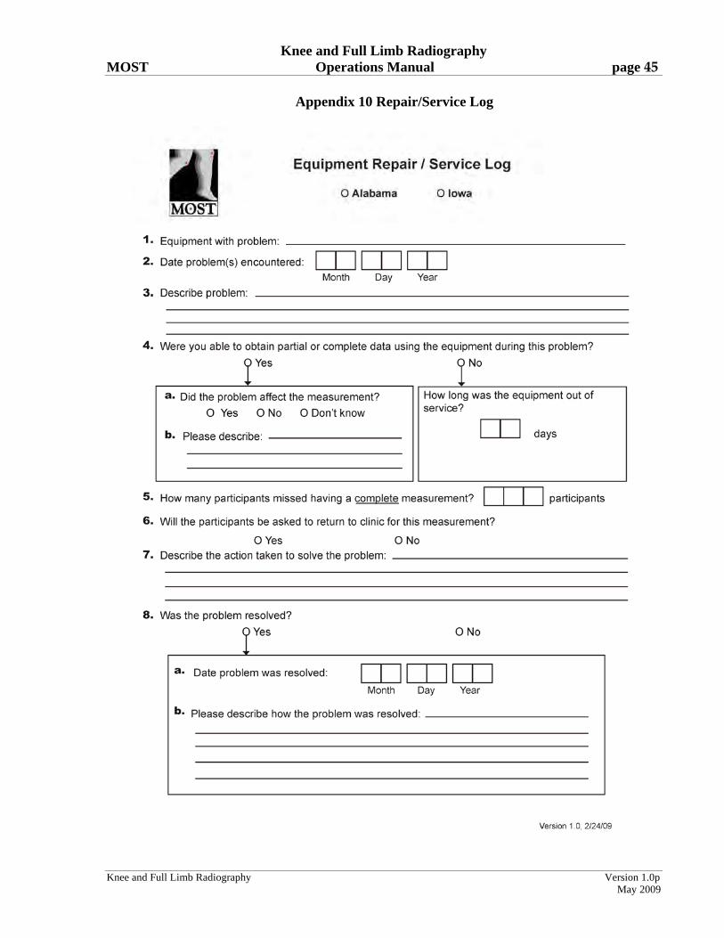
Appendix 10 Repair/Service Log
Knee and Full Limb Radiography Version 1.0p
May 2009