Embed Size (px)
Citation preview
Motion-induced error reduction by combiningFourier transform profilometry withphase-shifting profilometry
BEIWEN LI, ZIPING LIU, AND SONG ZHANG*
School of Mechanical Engineering, Purdue University, West Lafayette, Indiana 47907, USA*[email protected]
Abstract: We propose a hybrid computational framework to reduce motion-induced measure-ment error by combining the Fourier transform profilometry (FTP) and phase-shifting profilome-try (PSP). The proposed method is composed of three major steps: Step 1 is to extract continuousrelative phase maps for each isolated object with single-shot FTP method and spatial phaseunwrapping; Step 2 is to obtain an absolute phase map of the entire scene using PSP method,albeit motion-induced errors exist on the extracted absolute phase map; and Step 3 is to shiftthe continuous relative phase maps from Step 1 to generate final absolute phase maps for eachisolated object by referring to the absolute phase map with error from Step 2. Experimentsdemonstrate the success of the proposed computational framework for measuring multiple iso-lated rapidly moving objects.
c© 2016 Optical Society of America
OCIS codes: (120.0120) Instrumentation, measurement, and metrology; (100.5088) Phase unwrapping; (110.5086)Phase unwrapping; (100.5070) Phase retrieval
References and links1. J. Geng, “Structured-light 3d surface imaging: a tutorial,” Adv. Opt. Photonics 3, 128–160 (2011).2. M. Takeda and K. Mutoh, “Fourier transform profilometry for the automatic measurement of 3-d object shapes,”
Appl. Opt. 22, 3977–3982 (1983).3. H. Guo and P. Huang, “3-d shape measurement by use of a modified fourier transform method,” Proc. SPIE 7066,
70660E (2008).4. L. Guo, X. Su, and J. Li, “Improved fourier transform profilometry for the automatic measurement of 3d object
shapes,” Opt. Eng. 29, 1439–1444 (1990).5. S. Zhang and S.-T. Yau, “High-speed three-dimensional shape measurement system using a modified two-plus-one
phase-shifting algorithm,” Opt. Eng. 46, 113603–113603 (2007).6. K. Creath, “Phase-measurement interferometry techniques,” Prog. Opt. 26, 349–393 (1988).7. P. S. Huang and S. Zhang, “Fast three-step phase-shifting algorithm,” Appl. Opt. 45, 5086–5091 (2006).8. H. Guo and P. S. Huang, “Absolute phase technique for the fourier transform method,” Opt. Eng. 48, 043609–043609
(2009).9. Y. Xiao, X. Su, Q. Zhang, and Z. Li, “3-d profilometry for the impact process with marked fringes tracking,”
Optoelectron. Eng. 34, 46–52 (2007).10. B. Budianto, P. Lun, and T.-C. Hsung, “Marker encoded fringe projection profilometry for efficient 3d model
acquisition,” Appl. Opt. 53, 7442–7453 (2014).11. Y.-Y. Cheng and J. C. Wyant, “Two-wavelength phase shifting interferometry,” Appl. Opt. 23, 4539–4543 (1984).12. Y.-Y. Cheng and J. C. Wyant, “Multiple-wavelength phase shifting interferometry,” Appl. Opt. 24, 804–807 (1985).13. D. P. Towers, J. D. C. Jones, and C. E. Towers, “Optimum frequency selection in multi-frequency interferometry,”
Opt. Lett. 28, 1–3 (2003).14. Y. Wang and S. Zhang, “Superfast multifrequency phase-shifting technique with optimal pulse width modulation,”
Opt. Express 19, 5143–5148 (2011).15. M. Servin, J. M. Padilla, A. Gonzalez, and G. Garnica, “Temporal phase-unwrapping of static surfaces with
2-sensitivity fringe-patterns,” Opt. Express 23, 15806–15815 (2015).16. S. Zhang, “Flexible 3d shape measurement using projector defocusing: Extended measurement range,” Opt. Lett. 35,
931–933 (2010).17. J. Pan, P. S. Huang, and F.-P. Chiang, “Color-coded binary fringe projection technique for 3-d shape measurement,”
Opt. Eng. 44, 023606–023606 (2005).18. Y. Wang and S. Zhang, “Novel phase coding method for absolute phase retrieval,” Opt. Lett. 37, 2067–2069 (2012).19. C. Zuo, Q. Chen, G. Gu, S. Feng, F. Feng, R. Li, and G. Shen, “High-speed three-dimensional shape measurement
for dynamic scenes using bi-frequency tripolar pulse-width-modulation fringe projection,” Opt. Lasers Eng. 51,953–960 (2013).
Vol. 24, No. 20 | 3 Oct 2016 | OPTICS EXPRESS 23289
#270575 http://dx.doi.org/10.1364/OE.24.023289 Journal © 2016 Received 15 Jul 2016; revised 15 Sep 2016; accepted 21 Sep 2016; published 28 Sep 2016
20. Y. Xing, C. Quan, and C. Tay, “A modified phase-coding method for absolute phase retrieval,” Opt. Lasers Eng. 87,97–102 (2016).
21. C. Zuo, Q. Chen, G. Gu, S. Feng, and F. Feng, “High-speed three-dimensional profilometry for multiple objects withcomplex shapes,” Opt. Express 20, 19493–19510 (2012).
22. Y. Wang, S. Zhang, and J. H. Oliver, “3-d shape measurement technique for multiple rapidly moving objects,” Opt.Express 19, 5149–5155 (2011).
23. P. Cong, Z. Xiong, Y. Zhang, S. Zhao, and F. Wu, “Accurate dynamic 3d sensing with fourier-assisted phase shifting,”IEEE J. Sel. Top. Signal Process 9, 396–408 (2015).
24. J.-S. Hyun and S. Zhang, “Enhanced two-frequency phase-shifting method,” Appl. Opt. 55, 4395–4401 (2016).25. Y. An, J.-S. Hyun, and S. Zhang, “Pixel-wise absolute phase unwrapping using geometric constraints of structured
light system,” Opt. Express 24, 18445–18459 (2016).26. B. Li, Y. An, and S. Zhang, “Single-shot absolute 3d shape measurement with fourier transform profilometry,” Appl.
Opt. 55, 5219–5225 (2016).27. K. Zhong, Z. Li, Y. Shi, C. Wang, and Y. Lei, “Fast phase measurement profilometry for arbitrary shape objects
without phase unwrapping,” Opt. Lasers Eng. 51, 1213–1222 (2013).28. W. Lohry, V. Chen, and S. Zhang, “Absolute three-dimensional shape measurement using coded fringe patterns
without phase unwrapping or projector calibration,” Opt. Express 22, 1287–1301 (2014).29. W. Lohry and S. Zhang, “High-speed absolute three-dimensional shape measurement using three binary dithered
patterns,” Opt. Express 22, 26752–26762 (2014).30. S. Heist, P. Lutzke, I. Schmidt, P. Dietrich, P. Kühmstedt, A. Tünnermann, and G. Notni, “High-speed three-
dimensional shape measurement using gobo projection,” Opt. Lasers Eng. 87, 90–96 (2016).31. S. Zhang, X. Li, and S.-T. Yau, “Multilevel quality-guided phase unwrapping algorithm for real-time three-
dimensional shape reconstruction,” Appl. Opt. 46, 50–57 (2007).32. B. Li, N. Karpinsky, and S. Zhang, “Novel calibration method for structured light system with an out-of-focus
projector,” Appl. Opt. 53, 3415–3426 (2014).33. S. Lei and S. Zhang, “Flexible 3-d shape measurement using projector defocusing,” Opt. Lett. 34, 3080–3082 (2009).34. Y. Wang and S. Zhang, “Three-dimensional shape measurement with binary dithered patterns,” Appl. Opt. 51,
6631–6636 (2012).35. Q. Kemao, “Windowed fourier transform for fringe pattern analysis,” Appl. Opt. 43, 2695–2702 (2004).36. Q. Kemao, “Two-dimensional windowed fourier transform for fringe pattern analysis: Principles, applications and
implementations,” Opt. Lasers Eng. 45, 304–317 (2007).37. P. Sandoz, “Wavelet transform as a processing tool in white-light interferometry,” Opt. Lett. 22, 1065–1067 (1997).38. J. Zhong and J. Weng, “Spatial carrier-fringe pattern analysis by means of wavelet transform: wavelet transform
profilometry,” Appl. Opt. 43, 4993–4998 (2004).
1. Introduction
The rapidly evolving three-dimensional (3D) shape measurement technologies have enjoyed awide applications ranging from industrial inspection to biomedical science. The non-contactstructured light technology has been increasingly appealing to researchers in many differentfields due to its flexibility and accuracy [1]. Yet a crucial challenge for this field of research is toperform accurate 3D shape measurement of dynamically moving or deformable objects, whichtypically introduces measurement errors caused by object motion.
To alleviate the measurement errors induced by object motion, it is desirable to reduce thenumber of fringe images required to reconstruct 3D geometry. The approaches that minimize thenumber of projection patterns include single-shot Fourier transform profilometry (FTP) [2], 1 + 1FTP approach [3], π-shift FTP approach [4], 2 + 1 phase-shifting approach [5] and three-stepphase-shifting profilometry (PSP) [6, 7]. The approach that requires least number of projectionpatterns is the standard FTP approach which extracts phase information within a single-shotfringe image. This property of FTP approach is extremely advantageous when rapid motion ispresent in the measured scene. Most single-shot FTP approaches adopt spatial phase unwrapping,which detects 2π discontinuities solely from the wrapped phase map itself and removes themby adding or subtracting integer k (x , y) multiples of 2π. This integer number k (x , y) is oftencalled fringe order. However, a fundamental limitation for spatial phase unwrapping is thatthe obtained unwrapped phase map is relative. This is simply because the phase value on aspatially unwrapped phase map is dependent on the phase value of the starting point withina connected component. As a result, it cannot handle scenes with spatially isolated object.
Vol. 24, No. 20 | 3 Oct 2016 | OPTICS EXPRESS 23290
Although researchers have come up with approaches that embed markers into the projectedsingle pattern [8–10], the absolute phase retrieval could be problematic if the embedded markersare not clear on an isolated object.
Temporal phase unwrapping, which obtains insights for fringe order k (x , y) by acquiringadditional information, has the advantage of robust absolute phase recovery especially forstatic scenes. Some widely adopted techniques include multi-frequency (or -wavelength) phaseshifting techniques [11–15], binary [16] or Gray [17] stripe coding strategies and phase codingstrategies [18–20]. These approaches commonly require many additional fringes (e.g. typicallymore than three) to determine the fringe order for absolute phase retrieval, which is undesirablefor dynamic scene measurements.
To address this limitation of temporal phase unwrapping, Zuo et al. [21] proposed a fourpattern strategy to further reduce the total number of patterns; Wang et al. [22] combinedspatial and temporal phase unwrapping within phase shifting plus gray coding framework. Theseapproaches can function well under majority cases especially when the object movement is notrapid. However, Zuo’s approach [21] still requires the imaged scene to remain stationary withinthe four consecutively captured frames, and Wang’s approach [22] requires the measured objectsto remain stationary within the first three phase shifted fringes of the entire fringe sequence,which are not valid assumptions if the object motion is extremely rapid. Cong et al. [23] proposeda Fourier-assisted PSP approach which corrects the phase shift error caused by motion assistedby FTP approach, yet in this particular research, the marker points are used to detect fringeorder, which could encounter similar problems as all marker based approaches mentioned above.Recently, our research group [24, 25] proposed to obtain absolute phase map with the assist ofgeometric constraints. Hyun and Zhang [24] proposed an enhanced two-frequency method toreduce the noise and improve the robustness of conventional two-frequency phase unwrapping,yet it still uses six images as required by conventional two-frequency method, where speed isstill a major concern. An et al. [25] introduced an absolute phase recovery framework that solelyuses geometric constraints to perform phase unwrapping. This method does not require capturingadditional images to determine the fringe order, and was lately combined with FTP to performsingle-shot absolute phase recovery [26]. However, this single-shot approach cannot handleobject depth variations that exceed 2π in phase domain [25], meaning that the measurement depthrange could be quite constrained since FTP method typically requires using a high-frequencypattern.
Apart from reducing motion-induced errors by modifying the phase computational frame-works, researchers are also seeking alternative solutions by adding more hardware. The ap-proaches that use more than one camera have been proven successful by several reported researchworks [27–30]. The fundamental mechanism behind this type of approaches lies in the fact thatany motion-induced measurement error will simultaneously appear in different cameras, andthus the correspondence detection won’t be affected. However, the cost of adding another cameracould be expensive especially when high measurement quality is required. Moreover, only thesampled area that is viewed by all imaging sensors (i.e. two cameras, one projector) can bereconstructed.
In this research, we propose a hybrid computational framework for motion-induced errorreduction. Our proposed approach uses a total of 4 patterns to conduct absolute 3D shapemeasurement. First of all, we perform single-shot phase extraction using FTP with a highfrequency pattern projection. Then, we identify each isolated object, and obtain continuousrelative phase map for each object through spatial phase unwrapping. To determine the rigid shiftfrom relative to absolute phase map, we use low-frequency three-step phase shifted patterns tofind extra information: Essentially, we use low-frequency three-step phase shifted patterns plusgeometric constraints to produce absolute phase map, yet phase errors caused by motion betweenthe three frames are inevitable. However, we can obtain insights by finding the most common
Vol. 24, No. 20 | 3 Oct 2016 | OPTICS EXPRESS 23291
integer fringe order shift ks from this PSP extracted phase map to FTP continuous relative phasemap. Our proposed method combines spatial and temporal phase unwrapping, in which we usespatial phase unwrapping to reduce motion-induced errors, and temporal phase unwrapping toobtain absolute phase map. Our proposed method does not involve any additional hardware formotion-induced error reduction. Experiments have demonstrated the success of our proposedcomputational framework for measuring multiple spatially isolated objects with rapid motion.
Section 2 introduces the relevant theoretical background and the framework of our proposedresearch; Section 3 illustrates the experimental validations of our proposed research; Section 4discusses the strengths and limitations of our proposed computational framework, and Section 5summaries our proposed research.
2. Principle
In this section, we will introduce the relevant theoretical foundations of this proposed framework,which include the principles of FTP, PSP, phase unwrapping with geometric constraints, themotion-induced error in PSP method to be addressed in this research, as well as our proposedhybrid absolute phase computational framework.
2.1. Fourier transform profilometry (FTP)
The basic principles of FTP approach can be expressed as follows: In theory, a typical fringeimage can be represented as
I (x , y) = I′(x , y) + I′′(x , y) cos[φ(x , y)], (1)
where I′(x , y) denotes the average intensity, I′′(x , y) stands for the intensity modulation, andφ(x , y) is the phase information to be extracted. According to the well-known Euler’s formula,Eq. (2) can be re-formulated as
I (x , y) = I′(x , y) +I′′(x , y)
2
[e jφ (x ,y ) + e− jφ (x ,y )
]. (2)
A band-pass filter that preserves only one of the conjugate frequency components can be appliedto produce the final image, which can be expressed as
I f (x , y) =I′′(x , y)
2e jφ (x ,y ) . (3)
After band-pass filtering, the phase can be extracted by
φ(x , y) = tan−1
Im[I f (x , y)
]Re[I f (x , y)
] , (4)
where Re[I f (x , y)
]and Im
[I f (x , y)
]respectively represent the real and the imaginary part
of the final image I f (x , y). Consequently, Eq. (4) produces a wrapped phase map with 2πdiscontinuities. To obtain a continuous phase map without 2π jumps, a spatial or temporal phaseunwrapping approach can be applied. In general, the key for phase unwrapping is to determinethe integer fringe order k (x , y) for each pixel which removes 2π discontinuities. The relationshipbetween a wrapped phase map and an unwrapped phase map can be expressed as
Φ(x , y) = φ(x , y) + 2π × k (x , y). (5)
Vol. 24, No. 20 | 3 Oct 2016 | OPTICS EXPRESS 23292
2.2. Phase shifting profilometry (PSP)
PSP method, different from single-shot FTP method, uses a set of phase shifted fringe imagesfor phase computation. For a three-step phase-shifting approach that requires least number ofphase shifting steps, the fringe images used can be described as
I1(x , y) = I′(x , y) + I′′(x , y) cos[φ(x , y) − 2π/3], (6)I2(x , y) = I′(x , y) + I′′(x , y) cos[φ(x , y)], (7)I3(x , y) = I′(x , y) + I′′(x , y) cos[φ(x , y) + 2π/3]. (8)
With the three phase shifted fringe images, the phase φ(x , y) can be extracted by simultaneouslysolving Eqs. (6)–(8):
φ(x , y) = tan−1
√3(I1 − I3)
2I2 − I1 − I3. (9)
Again, the phase φ(x , y) obtained here has 2π discontinuities. Similarly, we can adopt a spatialor temporal phase unwrapping framework to obtain the unwrapped phase map.
2.3. Phase unwrapping using geometric constraint
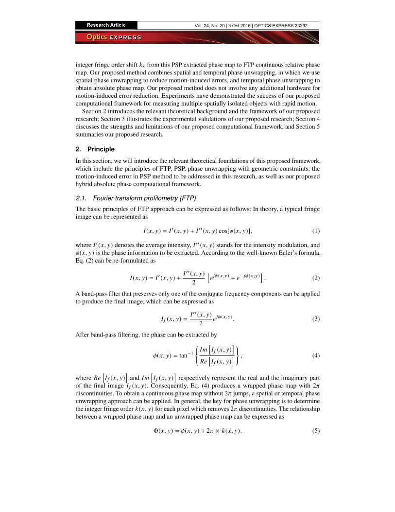
As recently proposed by An et al. [25], one of the methods that removes 2π discontinuities ona wrapped phase map is by using geometric constraints. Figure 1 illustrates the fundamentalprinciple of this type of methods. Suppose the region that the camera captures on the CCDcensor is a flat plane located at zw = zmin , which is the closet measurement depth plane ofinterest, the same region can be mapped to the projector DMD sensor which creates a pixelateartificial absolute phase map Φmin . This generated phase map Φmin can be used to locate 2πdiscontinuities on a wrapped phase map. The detailed procedures of zmin determination andΦmin generation can be found in [25].
CCD DMD
zw = zmin
ow
ywx
w
zw
Lens
Lens
Virtual plane
Mapped region
of virtual plane
Fig. 1. Illustration of the geometric mapping between the camera image region and thecorresponding region on the projector sensor if a virtual plane is positioned as zmin [25].
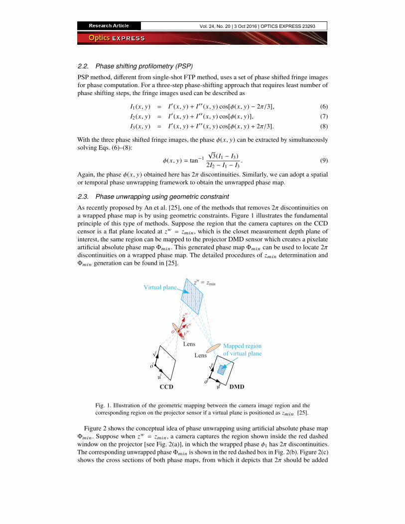
Figure 2 shows the conceptual idea of phase unwrapping using artificial absolute phase mapΦmin . Suppose when zw = zmin , a camera captures the region shown inside the red dashedwindow on the projector [see Fig. 2(a)], in which the wrapped phase φ1 has 2π discontinuities.The corresponding unwrapped phaseΦmin is shown in the red dashed box in Fig. 2(b). Figure 2(c)shows the cross sections of both phase maps, from which it depicts that 2π should be added
Vol. 24, No. 20 | 3 Oct 2016 | OPTICS EXPRESS 23293
to the wrapped phase when the phase φ1 is below Φmin . The same idea also applies when thephase φ is captured at z > zmin as illustrated in the solid blue window, where 2π is added to thewrapped phase φ if below Φmin .
(a)
min
(b)
min
2
x
(c)
A B Cx x
2
6min
x
(d)
Fig. 2. Concept of removing 2π discontinuities using the minimum phase map determinedfrom geometric constraints [25]. (a) Regions acquired by the camera at different depth zplane: red dashed windowed region where z = zmin and solid blue windowed region wherez > zmin ; (b) Φmin and Φ defined on the projector; (c) cross sections of the wrapped phasemaps, φ1 and φ, and their correctly unwrapped phase map Φmin and Φ; (d) case for usingfringe patterns with four periods.
Now we consider a more general case, as shown in Fig. 2(d), where the captured camera imagecontains more fringe periods, different fringe order k (x , y) should be added to the wrapped phaseφ depending on its difference with Φmin . The fringe order k (x , y) can be determined as follows:
2π × (k − 1) < Φmin − φ < 2π × k , (10)
or equivalently:
k = ceil[Φmin − φ
2π
], (11)
where ceil[] operator returns the closest upper integer value.
2.4. Motion-induced error in PSP
PSP works really well under the assumption that the object is quasi-static during the processof capturing multiple phase-shifted fringe images. However, the object movement can causemeasurement error if the fundamental assumption of a phase-shifting method is violated. If thesampling speed of the system is fast enough, this type of error is not obvious. However, whenthe sampling speed cannot keep up with object movement, this type of error is pronounced andcan be dominant.
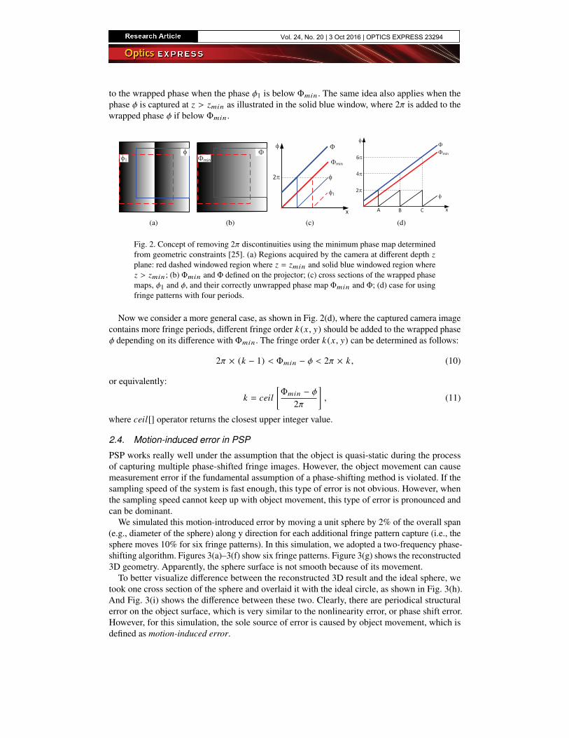
We simulated this motion-introduced error by moving a unit sphere by 2% of the overall span(e.g., diameter of the sphere) along y direction for each additional fringe pattern capture (i.e., thesphere moves 10% for six fringe patterns). In this simulation, we adopted a two-frequency phase-shifting algorithm. Figures 3(a)–3(f) show six fringe patterns. Figure 3(g) shows the reconstructed3D geometry. Apparently, the sphere surface is not smooth because of its movement.
To better visualize difference between the reconstructed 3D result and the ideal sphere, wetook one cross section of the sphere and overlaid it with the ideal circle, as shown in Fig. 3(h).And Fig. 3(i) shows the difference between these two. Clearly, there are periodical structuralerror on the object surface, which is very similar to the nonlinearity error, or phase shift error.However, for this simulation, the sole source of error is caused by object movement, which isdefined as motion-induced error.
Vol. 24, No. 20 | 3 Oct 2016 | OPTICS EXPRESS 23294
(a) (b) (c) (d) (e) (f)
(g)
-0.5 0 0.5X
0
0.2
0.4Z
ReconstructedIdeal
(h)
-0.5 0 0.5X
-5
0
5
Err
or
×10-3
(i)
Fig. 3. Simulation of motion-induced measurement error. (a) - (c) high frequency phaseshifted patterns; (d) - (f) low frequency phase shifted patterns; (g) reconstructed 3D shape;(h) a cross section of (g) and the ideal sphere; (i) difference between the reconstructed sphereand the ideal sphere.
2.5. Proposed hybrid absolute phase computational framework
The major type of error that this paper aims at addressing is the measurement error caused byobject motion. As discussed in the previous subsection, the motion-introduced error of PSPmethod is caused by the violations of the fundamental assumption of phase-shifting method:object remain static during the capture of required number of phase shifted fringe patterns. It iswell known that the FTP method can extract phase information within one single-shot fringeimage, which is extremely advantageous when measuring scenes with high speed motion, yet thepixel-by-pixel absolute phase retrieval problem remains nontrivial for FTP approaches withoutcapturing any additional fringe patterns. We recently proposed to use geometric constraints ofthe structured light system to perform pixel-wise absolute phase unwrapping [26], yet is depthrange is confined to a small range [25].
To address enhance the capability of our previously proposed method [26] by extending itsdepth range to a substantially large range, we propose a hybrid computational framework thatcombines FTP with PSP to address this limitation. We first perform single-shot FTP and spatialphase unwrapping to produce continuous relative phase map Φr for each spatially isolated object.Suppose we have an additional set of low frequency three-step phase shifted patterns, the phaseextracted from this set of three patterns can be unwrapped by artificial phase map Φmin toproduce a rough absolute phase map Φe , yet measurement errors are present owing to the objectmotion within the three frames. However, if under the assumption that the motion-induced errorsis not predominant on the entire phase map, we can still take advantage of this phase map to findthe rigid fringe order shift ks from relative phase map to the final absolute phase map.
By using three additional phase-shifted fringe patterns with a lower frequency, the proposedmethod increases the depth range of our previous method [26]. For example, if the angle betweencamera and projector optical axes is around θ = 13◦ and the overall projection range is 400mm, the proposed method can handle approximately 348 mm depth range for a noise-freesystem [25]. In contrast, the method proposed in [26] is confined to approximately 27 mm, which
Vol. 24, No. 20 | 3 Oct 2016 | OPTICS EXPRESS 23295
is approximately 13 times smaller than our proposed method.
Unwrapped phase
map with error
Φe
Unwrapped phase
maps for each object
Φr
Isolated objects
Three-step phase shifting
Object
segmentation
Spatial phase
unwrapping
FTP
Find fringe
order shift ks
High-frequency
fringe image
Phase-shifted
low frequency
fringe image
Absolute phase
Φa
Motion
compensation
Phase unwrapping with
geometric constraints
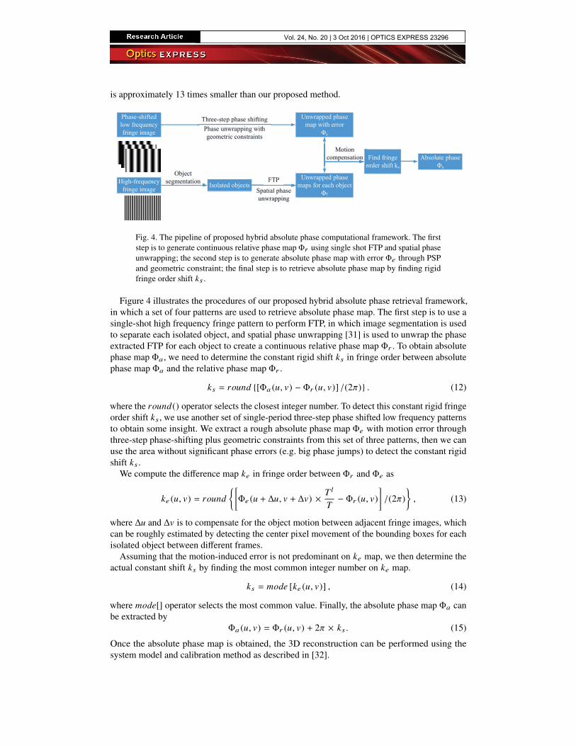
Fig. 4. The pipeline of proposed hybrid absolute phase computational framework. The firststep is to generate continuous relative phase map Φr using single shot FTP and spatial phaseunwrapping; the second step is to generate absolute phase map with error Φe through PSPand geometric constraint; the final step is to retrieve absolute phase map by finding rigidfringe order shift ks .
Figure 4 illustrates the procedures of our proposed hybrid absolute phase retrieval framework,in which a set of four patterns are used to retrieve absolute phase map. The first step is to use asingle-shot high frequency fringe pattern to perform FTP, in which image segmentation is usedto separate each isolated object, and spatial phase unwrapping [31] is used to unwrap the phaseextracted FTP for each object to create a continuous relative phase map Φr . To obtain absolutephase map Φa , we need to determine the constant rigid shift ks in fringe order between absolutephase map Φa and the relative phase map Φr .
ks = round {[Φa (u, v) − Φr (u, v)] /(2π)} . (12)
where the round() operator selects the closest integer number. To detect this constant rigid fringeorder shift ks , we use another set of single-period three-step phase shifted low frequency patternsto obtain some insight. We extract a rough absolute phase map Φe with motion error throughthree-step phase-shifting plus geometric constraints from this set of three patterns, then we canuse the area without significant phase errors (e.g. big phase jumps) to detect the constant rigidshift ks .
We compute the difference map ke in fringe order between Φr and Φe as
ke (u, v) = round{[Φe (u + ∆u, v + ∆v) ×
T l
T− Φr (u, v)
]/(2π)
}, (13)
where ∆u and ∆v is to compensate for the object motion between adjacent fringe images, whichcan be roughly estimated by detecting the center pixel movement of the bounding boxes for eachisolated object between different frames.
Assuming that the motion-induced error is not predominant on ke map, we then determine theactual constant shift ks by finding the most common integer number on ke map.
ks = mode [ke (u, v)] , (14)
where mode[] operator selects the most common value. Finally, the absolute phase map Φa canbe extracted by
Φa (u, v) = Φr (u, v) + 2π × ks . (15)
Once the absolute phase map is obtained, the 3D reconstruction can be performed using thesystem model and calibration method as described in [32].
Vol. 24, No. 20 | 3 Oct 2016 | OPTICS EXPRESS 23296
3. Experiments
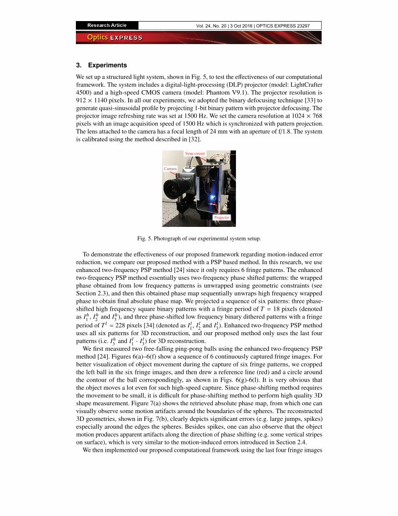
We set up a structured light system, shown in Fig. 5, to test the effectiveness of our computationalframework. The system includes a digital-light-processing (DLP) projector (model: LightCrafter4500) and a high-speed CMOS camera (model: Phantom V9.1). The projector resolution is912 × 1140 pixels. In all our experiments, we adopted the binary defocusing technique [33] togenerate quasi-sinusoidal profile by projecting 1-bit binary pattern with projector defocusing. Theprojector image refreshing rate was set at 1500 Hz. We set the camera resolution at 1024 × 768pixels with an image acquisition speed of 1500 Hz which is synchronized with pattern projection.The lens attached to the camera has a focal length of 24 mm with an aperture of f/1.8. The systemis calibrated using the method described in [32].
Camera
Projector
Sync circuit
Fig. 5. Photograph of our experimental system setup.
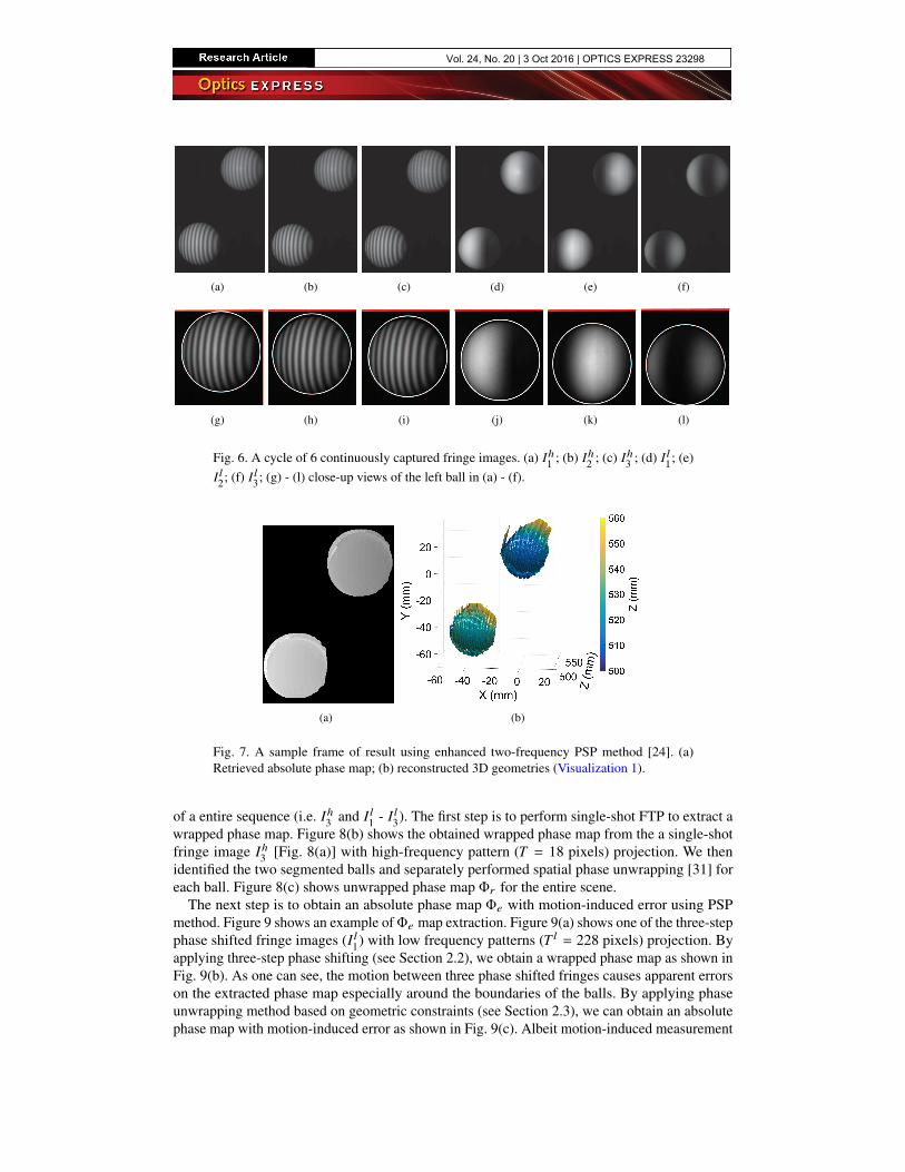
To demonstrate the effectiveness of our proposed framework regarding motion-induced errorreduction, we compare our proposed method with a PSP based method. In this research, we useenhanced two-frequency PSP method [24] since it only requires 6 fringe patterns. The enhancedtwo-frequency PSP method essentially uses two-frequency phase shifted patterns: the wrappedphase obtained from low frequency patterns is unwrapped using geometric constraints (seeSection 2.3), and then this obtained phase map sequentially unwraps high frequency wrappedphase to obtain final absolute phase map. We projected a sequence of six patterns: three phase-shifted high frequency square binary patterns with a fringe period of T = 18 pixels (denotedas Ih1 , Ih2 and Ih3 ), and three phase-shifted low frequency binary dithered patterns with a fringeperiod of T l = 228 pixels [34] (denoted as I l1, I l2 and I l3). Enhanced two-frequency PSP methoduses all six patterns for 3D reconstruction, and our proposed method only uses the last fourpatterns (i.e. Ih3 and I l1 - I l3) for 3D reconstruction.
We first measured two free-falling ping-pong balls using the enhanced two-frequency PSPmethod [24]. Figures 6(a)–6(f) show a sequence of 6 continuously captured fringe images. Forbetter visualization of object movement during the capture of six fringe patterns, we croppedthe left ball in the six fringe images, and then drew a reference line (red) and a circle aroundthe contour of the ball correspondingly, as shown in Figs. 6(g)-6(l). It is very obvious thatthe object moves a lot even for such high-speed capture. Since phase-shifting method requiresthe movement to be small, it is difficult for phase-shifting method to perform high quality 3Dshape measurement. Figure 7(a) shows the retrieved absolute phase map, from which one canvisually observe some motion artifacts around the boundaries of the spheres. The reconstructed3D geometries, shown in Fig. 7(b), clearly depicts significant errors (e.g. large jumps, spikes)especially around the edges the spheres. Besides spikes, one can also observe that the objectmotion produces apparent artifacts along the direction of phase shifting (e.g. some vertical stripeson surface), which is very similar to the motion-induced errors introduced in Section 2.4.
We then implemented our proposed computational framework using the last four fringe images
Vol. 24, No. 20 | 3 Oct 2016 | OPTICS EXPRESS 23297
(a) (b) (c) (d) (e) (f)
(g) (h) (i) (j) (k) (l)
Fig. 6. A cycle of 6 continuously captured fringe images. (a) Ih1 ; (b) Ih2 ; (c) Ih3 ; (d) I l1; (e)I l2; (f) I l3; (g) - (l) close-up views of the left ball in (a) - (f).
(a) (b)
Fig. 7. A sample frame of result using enhanced two-frequency PSP method [24]. (a)Retrieved absolute phase map; (b) reconstructed 3D geometries (Visualization 1).
of a entire sequence (i.e. Ih3 and I l1 - I l3). The first step is to perform single-shot FTP to extract awrapped phase map. Figure 8(b) shows the obtained wrapped phase map from the a single-shotfringe image Ih3 [Fig. 8(a)] with high-frequency pattern (T = 18 pixels) projection. We thenidentified the two segmented balls and separately performed spatial phase unwrapping [31] foreach ball. Figure 8(c) shows unwrapped phase map Φr for the entire scene.
The next step is to obtain an absolute phase map Φe with motion-induced error using PSPmethod. Figure 9 shows an example ofΦe map extraction. Figure 9(a) shows one of the three-stepphase shifted fringe images (I l1) with low frequency patterns (T l = 228 pixels) projection. Byapplying three-step phase shifting (see Section 2.2), we obtain a wrapped phase map as shown inFig. 9(b). As one can see, the motion between three phase shifted fringes causes apparent errorson the extracted phase map especially around the boundaries of the balls. By applying phaseunwrapping method based on geometric constraints (see Section 2.3), we can obtain an absolutephase map with motion-induced error as shown in Fig. 9(c). Albeit motion-induced measurement
Vol. 24, No. 20 | 3 Oct 2016 | OPTICS EXPRESS 23298
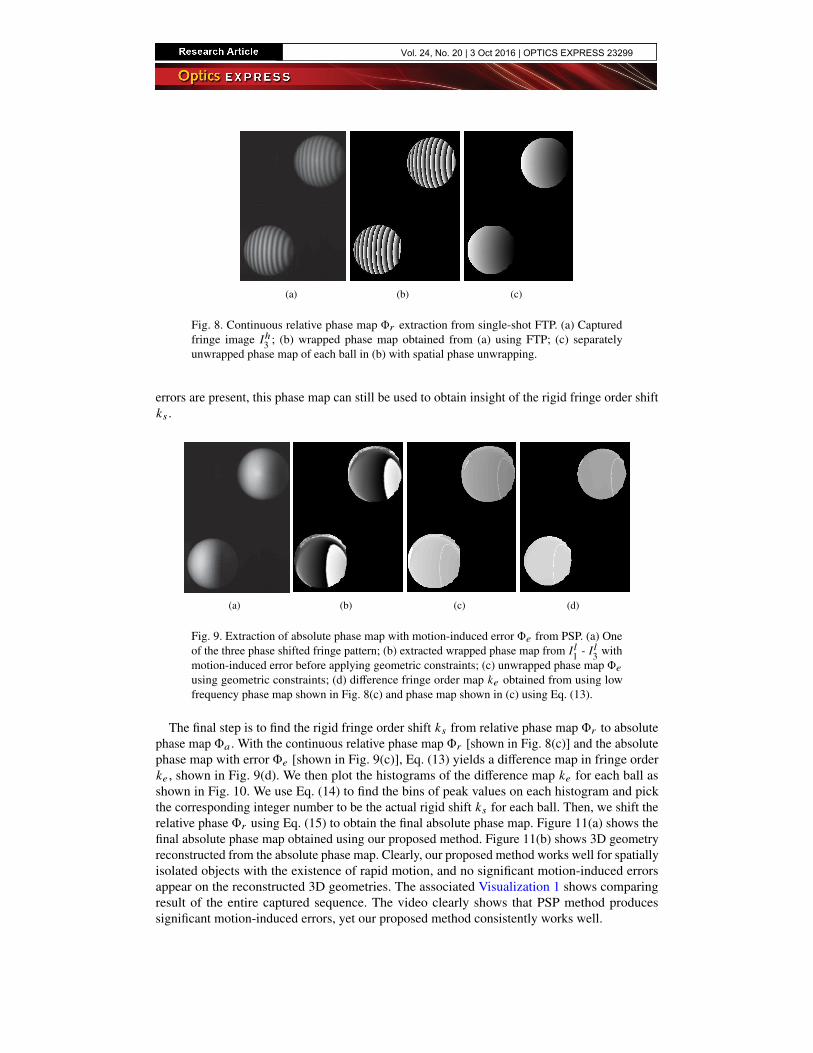
(a) (b) (c)
Fig. 8. Continuous relative phase map Φr extraction from single-shot FTP. (a) Capturedfringe image Ih3 ; (b) wrapped phase map obtained from (a) using FTP; (c) separatelyunwrapped phase map of each ball in (b) with spatial phase unwrapping.
errors are present, this phase map can still be used to obtain insight of the rigid fringe order shiftks .
(a) (b) (c) (d)
Fig. 9. Extraction of absolute phase map with motion-induced error Φe from PSP. (a) Oneof the three phase shifted fringe pattern; (b) extracted wrapped phase map from I l1 - I l3 withmotion-induced error before applying geometric constraints; (c) unwrapped phase map Φeusing geometric constraints; (d) difference fringe order map ke obtained from using lowfrequency phase map shown in Fig. 8(c) and phase map shown in (c) using Eq. (13).
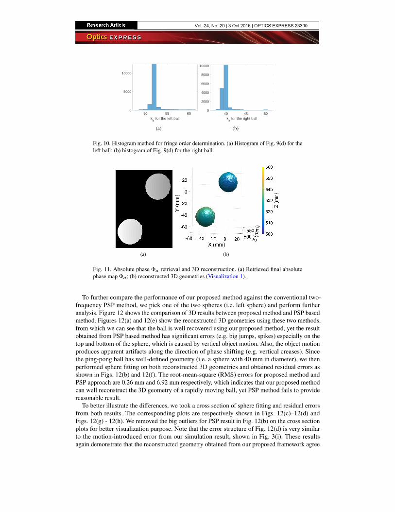
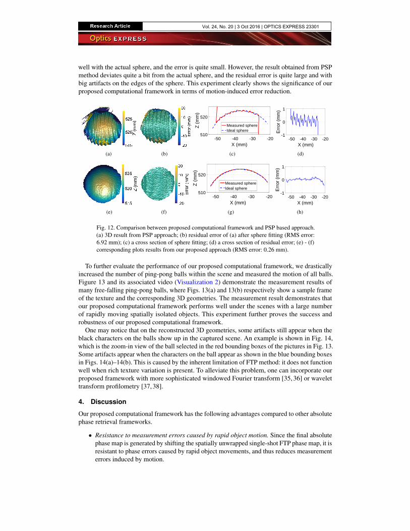
The final step is to find the rigid fringe order shift ks from relative phase map Φr to absolutephase map Φa . With the continuous relative phase map Φr [shown in Fig. 8(c)] and the absolutephase map with error Φe [shown in Fig. 9(c)], Eq. (13) yields a difference map in fringe orderke , shown in Fig. 9(d). We then plot the histograms of the difference map ke for each ball asshown in Fig. 10. We use Eq. (14) to find the bins of peak values on each histogram and pickthe corresponding integer number to be the actual rigid shift ks for each ball. Then, we shift therelative phase Φr using Eq. (15) to obtain the final absolute phase map. Figure 11(a) shows thefinal absolute phase map obtained using our proposed method. Figure 11(b) shows 3D geometryreconstructed from the absolute phase map. Clearly, our proposed method works well for spatiallyisolated objects with the existence of rapid motion, and no significant motion-induced errorsappear on the reconstructed 3D geometries. The associated Visualization 1 shows comparingresult of the entire captured sequence. The video clearly shows that PSP method producessignificant motion-induced errors, yet our proposed method consistently works well.
Vol. 24, No. 20 | 3 Oct 2016 | OPTICS EXPRESS 23299
50 55 60k
e for the left ball
0
5000
10000
(a)
40 45 50k
e for the right ball
0
2000
4000
6000
8000
10000
(b)
Fig. 10. Histogram method for fringe order determination. (a) Histogram of Fig. 9(d) for theleft ball; (b) histogram of Fig. 9(d) for the right ball.
(a) (b)
Fig. 11. Absolute phase Φa retrieval and 3D reconstruction. (a) Retrieved final absolutephase map Φa ; (b) reconstructed 3D geometries (Visualization 1).
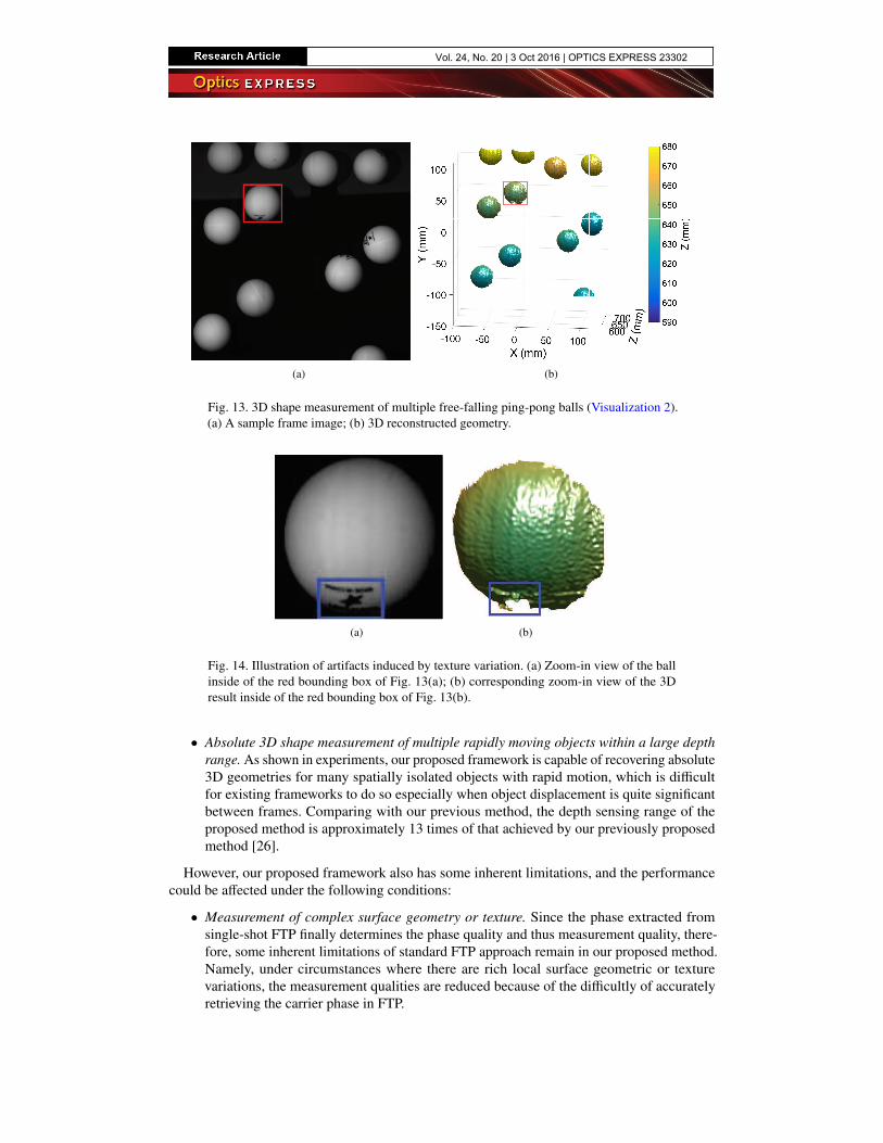
To further compare the performance of our proposed method against the conventional two-frequency PSP method, we pick one of the two spheres (i.e. left sphere) and perform furtheranalysis. Figure 12 shows the comparison of 3D results between proposed method and PSP basedmethod. Figures 12(a) and 12(e) show the reconstructed 3D geometries using these two methods,from which we can see that the ball is well recovered using our proposed method, yet the resultobtained from PSP based method has significant errors (e.g. big jumps, spikes) especially on thetop and bottom of the sphere, which is caused by vertical object motion. Also, the object motionproduces apparent artifacts along the direction of phase shifting (e.g. vertical creases). Sincethe ping-pong ball has well-defined geometry (i.e. a sphere with 40 mm in diameter), we thenperformed sphere fitting on both reconstructed 3D geometries and obtained residual errors asshown in Figs. 12(b) and 12(f). The root-mean-square (RMS) errors for proposed method andPSP approach are 0.26 mm and 6.92 mm respectively, which indicates that our proposed methodcan well reconstruct the 3D geometry of a rapidly moving ball, yet PSP method fails to providereasonable result.
To better illustrate the differences, we took a cross section of sphere fitting and residual errorsfrom both results. The corresponding plots are respectively shown in Figs. 12(c)–12(d) andFigs. 12(g) - 12(h). We removed the big outliers for PSP result in Fig. 12(b) on the cross sectionplots for better visualization purpose. Note that the error structure of Fig. 12(d) is very similarto the motion-introduced error from our simulation result, shown in Fig. 3(i). These resultsagain demonstrate that the reconstructed geometry obtained from our proposed framework agree
Vol. 24, No. 20 | 3 Oct 2016 | OPTICS EXPRESS 23300
well with the actual sphere, and the error is quite small. However, the result obtained from PSPmethod deviates quite a bit from the actual sphere, and the residual error is quite large and withbig artifacts on the edges of the sphere. This experiment clearly shows the significance of ourproposed computational framework in terms of motion-induced error reduction.
(a) (b)
-50 -40 -30 -20X (mm)
510
520
Z (
mm
)
Measured sphereIdeal sphere
(c)
-50 -40 -30 -20X (mm)
-1
0
1
Err
or (
mm
)
(d)
(e) (f)
-50 -40 -30 -20X (mm)
510
520
Z (
mm
)
Measured sphereIdeal sphere
(g)
-50 -40 -30 -20X (mm)
-1
0
1
Err
or (
mm
)
(h)
Fig. 12. Comparison between proposed computational framework and PSP based approach.(a) 3D result from PSP approach; (b) residual error of (a) after sphere fitting (RMS error:6.92 mm); (c) a cross section of sphere fitting; (d) a cross section of residual error; (e) - (f)corresponding plots results from our proposed approach (RMS error: 0.26 mm).
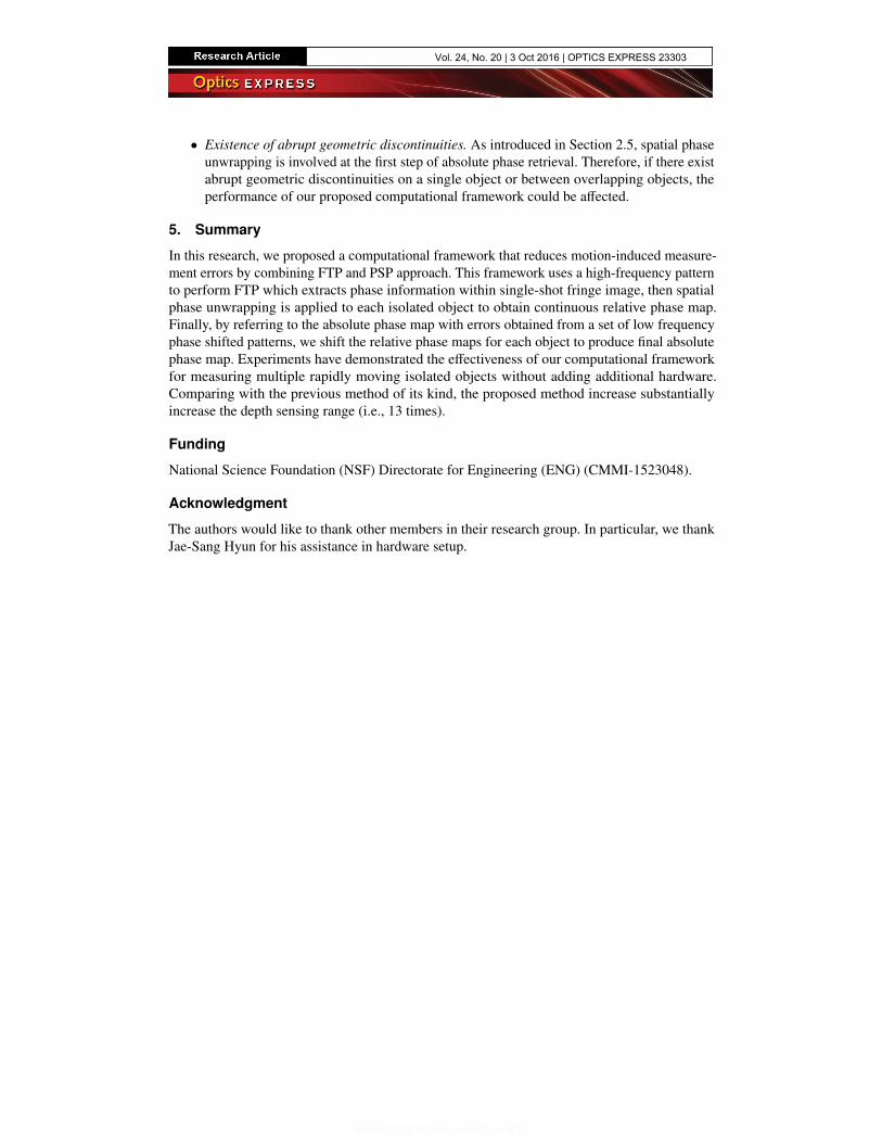
To further evaluate the performance of our proposed computational framework, we drasticallyincreased the number of ping-pong balls within the scene and measured the motion of all balls.Figure 13 and its associated video (Visualization 2) demonstrate the measurement results ofmany free-falling ping-pong balls, where Figs. 13(a) and 13(b) respectively show a sample frameof the texture and the corresponding 3D geometries. The measurement result demonstrates thatour proposed computational framework performs well under the scenes with a large numberof rapidly moving spatially isolated objects. This experiment further proves the success androbustness of our proposed computational framework.
One may notice that on the reconstructed 3D geometries, some artifacts still appear when theblack characters on the balls show up in the captured scene. An example is shown in Fig. 14,which is the zoom-in view of the ball selected in the red bounding boxes of the pictures in Fig. 13.Some artifacts appear when the characters on the ball appear as shown in the blue bounding boxesin Figs. 14(a)–14(b). This is caused by the inherent limitation of FTP method: it does not functionwell when rich texture variation is present. To alleviate this problem, one can incorporate ourproposed framework with more sophisticated windowed Fourier transform [35, 36] or wavelettransform profilometry [37, 38].
4. Discussion
Our proposed computational framework has the following advantages compared to other absolutephase retrieval frameworks.
• Resistance to measurement errors caused by rapid object motion. Since the final absolutephase map is generated by shifting the spatially unwrapped single-shot FTP phase map, it isresistant to phase errors caused by rapid object movements, and thus reduces measurementerrors induced by motion.
Vol. 24, No. 20 | 3 Oct 2016 | OPTICS EXPRESS 23301
(a) (b)
Fig. 13. 3D shape measurement of multiple free-falling ping-pong balls (Visualization 2).(a) A sample frame image; (b) 3D reconstructed geometry.
(a) (b)
Fig. 14. Illustration of artifacts induced by texture variation. (a) Zoom-in view of the ballinside of the red bounding box of Fig. 13(a); (b) corresponding zoom-in view of the 3Dresult inside of the red bounding box of Fig. 13(b).
• Absolute 3D shape measurement of multiple rapidly moving objects within a large depthrange. As shown in experiments, our proposed framework is capable of recovering absolute3D geometries for many spatially isolated objects with rapid motion, which is difficultfor existing frameworks to do so especially when object displacement is quite significantbetween frames. Comparing with our previous method, the depth sensing range of theproposed method is approximately 13 times of that achieved by our previously proposedmethod [26].
However, our proposed framework also has some inherent limitations, and the performancecould be affected under the following conditions:
• Measurement of complex surface geometry or texture. Since the phase extracted fromsingle-shot FTP finally determines the phase quality and thus measurement quality, there-fore, some inherent limitations of standard FTP approach remain in our proposed method.Namely, under circumstances where there are rich local surface geometric or texturevariations, the measurement qualities are reduced because of the difficultly of accuratelyretrieving the carrier phase in FTP.
Vol. 24, No. 20 | 3 Oct 2016 | OPTICS EXPRESS 23302
• Existence of abrupt geometric discontinuities. As introduced in Section 2.5, spatial phaseunwrapping is involved at the first step of absolute phase retrieval. Therefore, if there existabrupt geometric discontinuities on a single object or between overlapping objects, theperformance of our proposed computational framework could be affected.
5. Summary
In this research, we proposed a computational framework that reduces motion-induced measure-ment errors by combining FTP and PSP approach. This framework uses a high-frequency patternto perform FTP which extracts phase information within single-shot fringe image, then spatialphase unwrapping is applied to each isolated object to obtain continuous relative phase map.Finally, by referring to the absolute phase map with errors obtained from a set of low frequencyphase shifted patterns, we shift the relative phase maps for each object to produce final absolutephase map. Experiments have demonstrated the effectiveness of our computational frameworkfor measuring multiple rapidly moving isolated objects without adding additional hardware.Comparing with the previous method of its kind, the proposed method increase substantiallyincrease the depth sensing range (i.e., 13 times).
Funding
National Science Foundation (NSF) Directorate for Engineering (ENG) (CMMI-1523048).
Acknowledgment
The authors would like to thank other members in their research group. In particular, we thankJae-Sang Hyun for his assistance in hardware setup.
Vol. 24, No. 20 | 3 Oct 2016 | OPTICS EXPRESS 23303


![Reminder Fourier Basis: t [0,1] nZnZ Fourier Series: Fourier Coefficient:](https://img.pdfslide.net/doc/110x75/56649d395503460f94a13929/reminder-fourier-basis-t-01-nznz-fourier-series-fourier-coefficient.jpg)