Embed Size (px)
Citation preview
Motion Planning Technologies forPlanetary Rovers and Manipulators
Eric T. BaumgartnerNASA’s Jet Propulsion Laboratory
International Workshop on Motion Planningin Virtual Environments
LAAS-CNRSToulouse, FranceJanuary 8, 2005
ETB-2JPL Cleareance CL#04-3909
Acknowledgments
• This paper summarizes the work of many people who contributed toboth the on-board software, ground software and operational strategies used to command and control the Mars Exploration Rovers, Spirit and Opportunity
• They are:– Rover Navigation
· Mark Maimone and Jeff Biesadecki– Robotic Arm
· Eric Baumgartner, Robert Bonitz, and Chris Leger– Rover Sequencing and Visualization Planner (RSVP)
· Brian Cooper, Frank Hartman, John Wright, Scott Maxwell, Jeng Yen• References
– E. Baumgartner, B. Bonitz, J. Melko, C. Leger and L. Shiraishi, “The Mars Exploration Rover Instrument Positioning System,” IEEE Aerospace Conf., 2005
– C. Leger, “Efficient Sensor/Model Based On-Line Collision Detection for Planetary Manipulators,” ICRA 2002.
– S. Goldberg, M. Maimone, and L. Matthies, “Stereo Vision and Rover Navigation Software for Planetary Exploration,” IEEE Aerospace Conf., 2002
ETB-3JPL Cleareance CL#04-3909
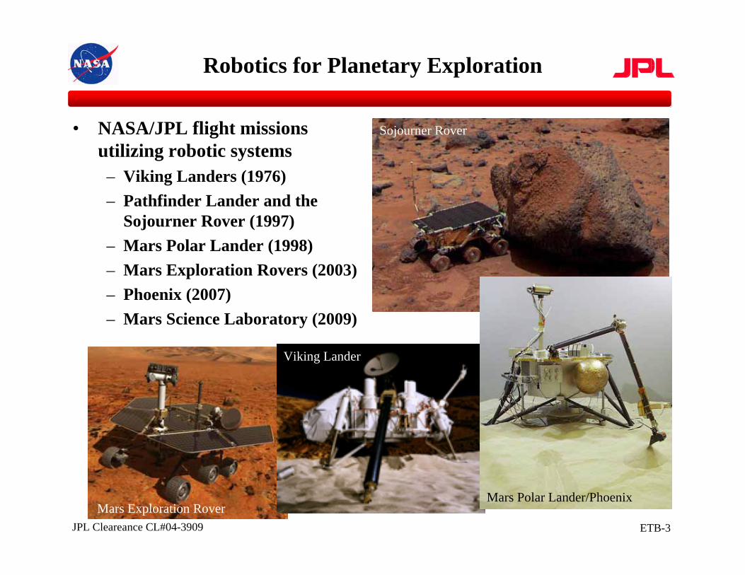
Robotics for Planetary Exploration
• NASA/JPL flight missions utilizing robotic systems– Viking Landers (1976)– Pathfinder Lander and the
Sojourner Rover (1997)– Mars Polar Lander (1998)– Mars Exploration Rovers (2003)– Phoenix (2007)– Mars Science Laboratory (2009)
Mars Exploration Rover
Viking Lander
Sojourner Rover
Mars Polar Lander/Phoenix
ETB-4JPL Cleareance CL#04-3909
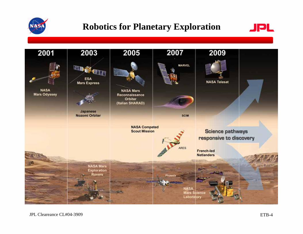
Robotics for Planetary Exploration
ETB-5JPL Cleareance CL#04-3909
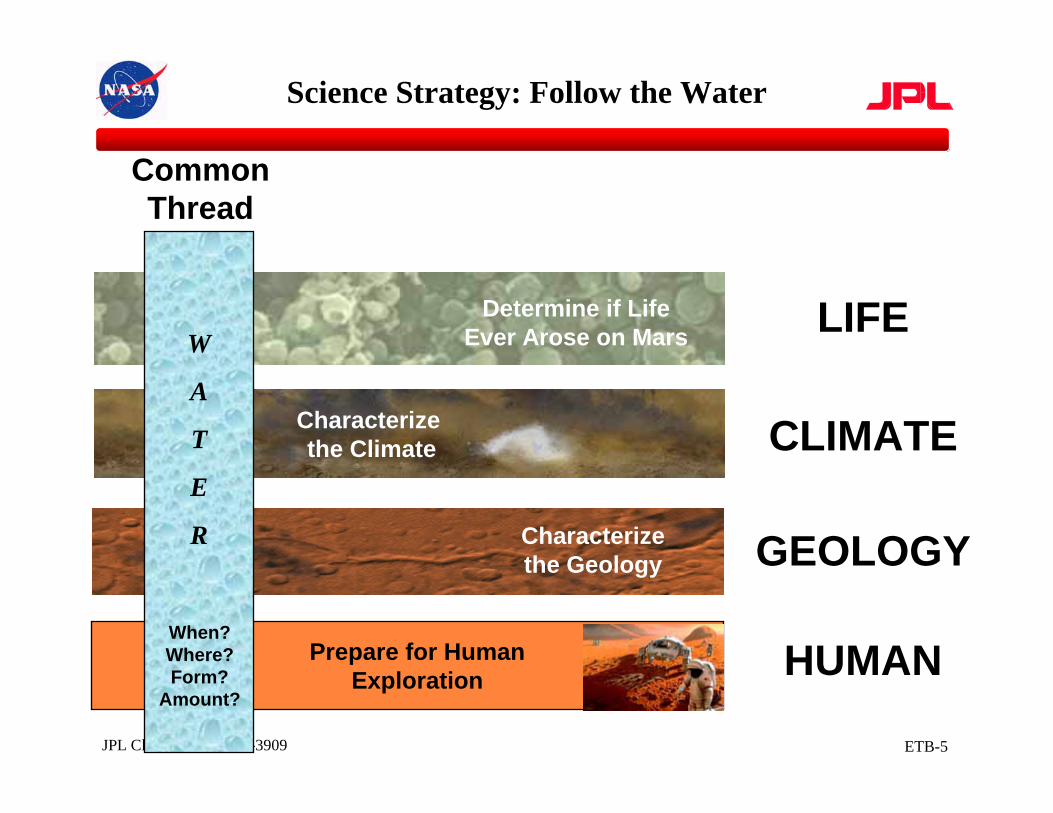
Characterize the Geology
Determine if Life Ever Arose on Mars
Characterizethe Climate
Prepare for Human Exploration
W
A
T
E
R
When?Where?Form?
Amount?
CommonThread
LIFE
CLIMATE
GEOLOGY
HUMAN
Science Strategy: Follow the Water
ETB-6JPL Cleareance CL#04-3909
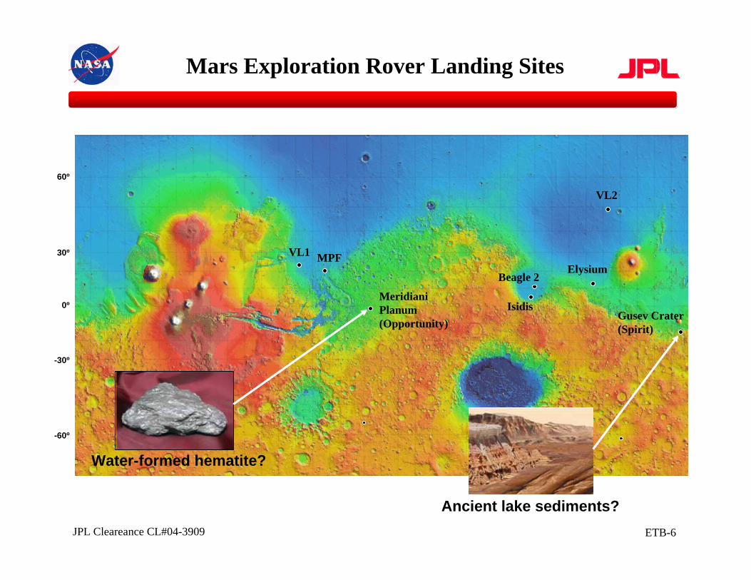
VL1 MPF
MeridianiPlanum(Opportunity)
Isidis
Elysium
VL2
Gusev Crater(Spirit)
Beagle 2
0º
30º
60º
-30º
-60º
Water-formed hematite?
Ancient lake sediments?
Mars Exploration Rover Landing Sites
ETB-7JPL Cleareance CL#04-3909
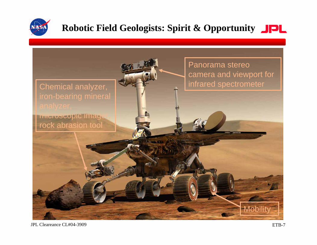
Robotic Field Geologists: Spirit & Opportunity
Panorama stereo camera and viewport for infrared spectrometerChemical analyzer,
iron-bearing mineral analyzer, microscopic imager, rock abrasion tool
Mobility
ETB-8JPL Cleareance CL#04-3909
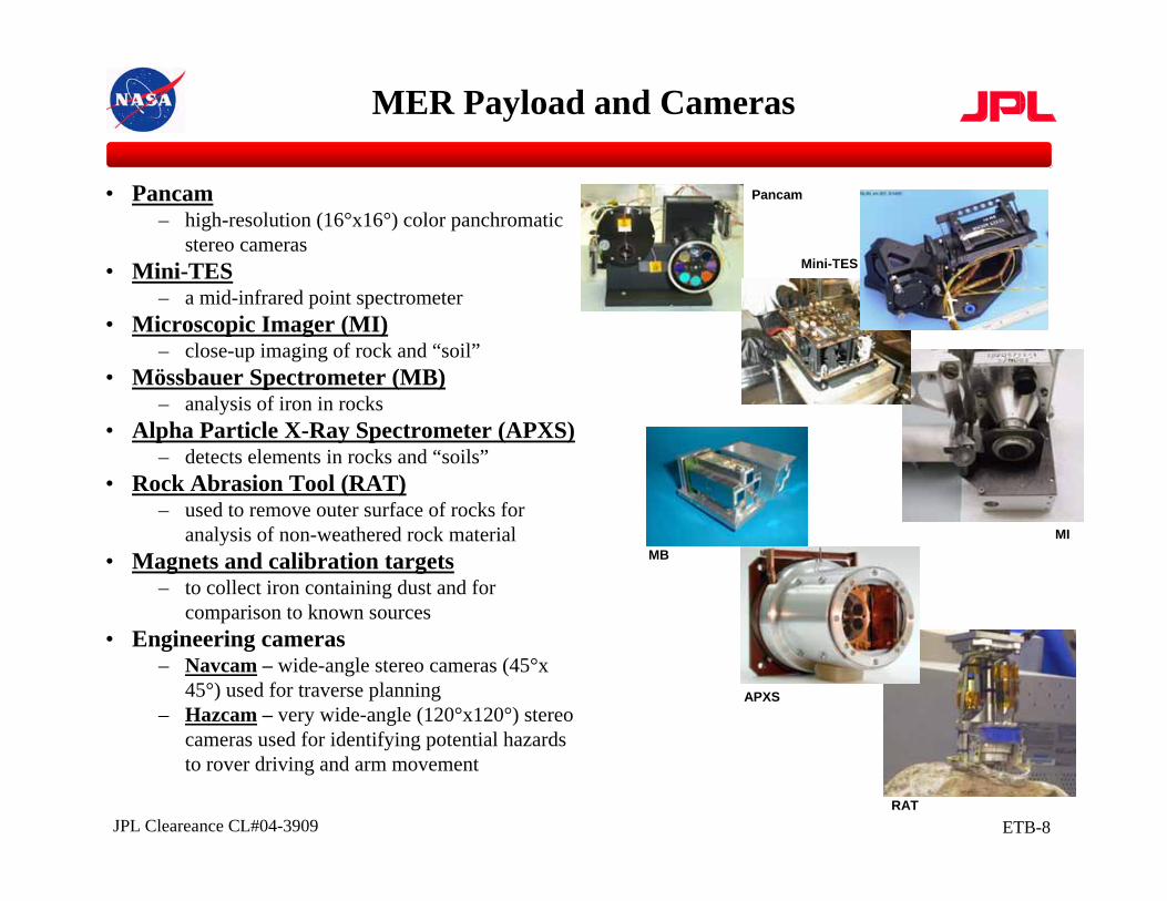
MER Payload and Cameras
Pancam
MIMB
APXS
RAT
Mini-TES
• Pancam– high-resolution (16°x16°) color panchromatic
stereo cameras• Mini-TES
– a mid-infrared point spectrometer• Microscopic Imager (MI)
– close-up imaging of rock and “soil”• Mössbauer Spectrometer (MB)
– analysis of iron in rocks• Alpha Particle X-Ray Spectrometer (APXS)
– detects elements in rocks and “soils”• Rock Abrasion Tool (RAT)
– used to remove outer surface of rocks for analysis of non-weathered rock material
• Magnets and calibration targets– to collect iron containing dust and for
comparison to known sources• Engineering cameras
– Navcam – wide-angle stereo cameras (45°x 45°) used for traverse planning
– Hazcam – very wide-angle (120°x120°) stereo cameras used for identifying potential hazards to rover driving and arm movement
ETB-9JPL Cleareance CL#04-3909
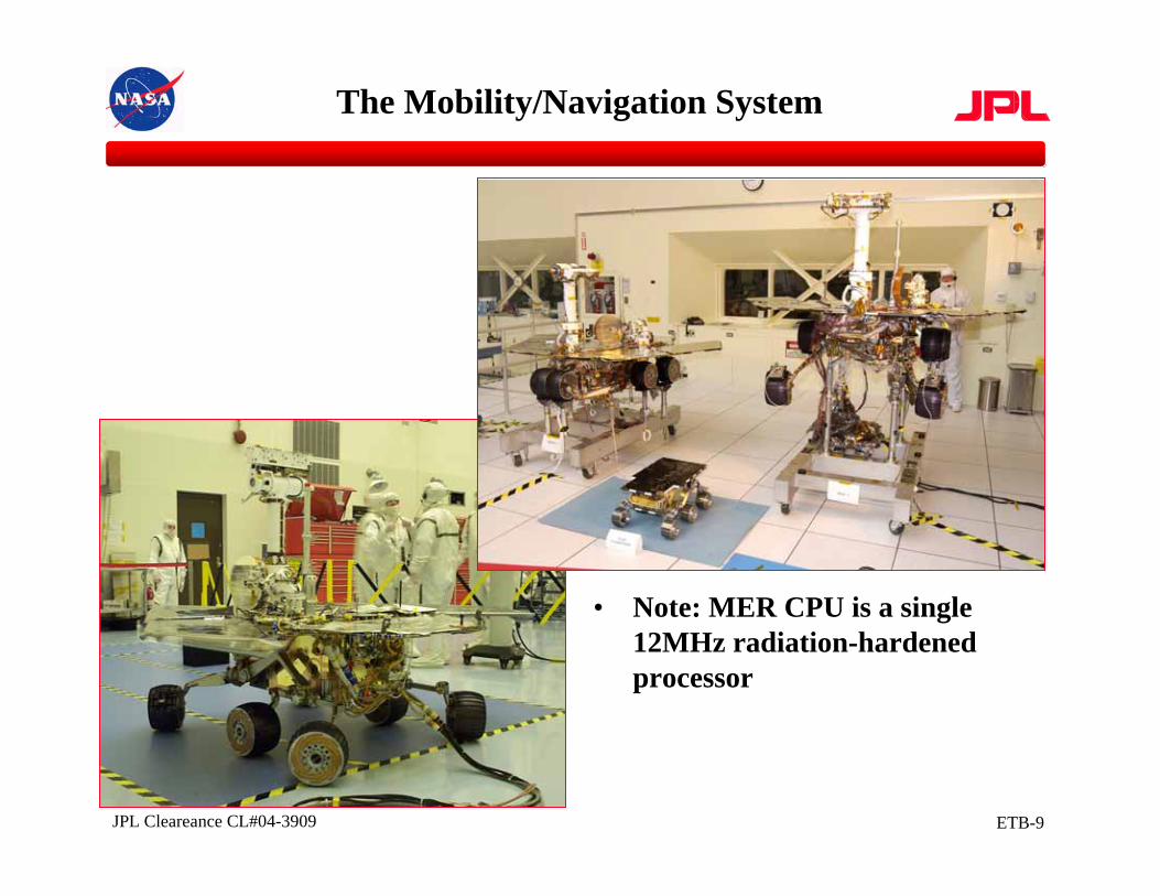
The Mobility/Navigation System
• Note: MER CPU is a single 12MHz radiation-hardened processor

ETB-10JPL Cleareance CL#04-3909
Instrument Deployment Device (IDD)
Azimuth (J1)
Elevation (J2)
Elbow (J3)
Wrist (J4)
Turret (J5)
APXS
MI
RATMB (hidden)
Front Hazcams
ETB-11JPL Cleareance CL#04-3909
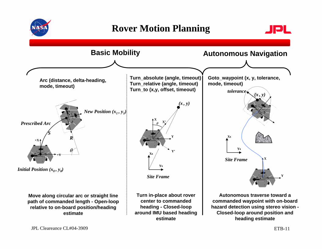
Rover Motion Planning
Initial Position (x0 , y0)
New Position (x1 , y1)
Prescribed Arc
+X
+Yθ
RS
Arc (distance, delta-heading, mode, timeout)
X
Y
θ
Y’
X’
Xs
Ys
(x , y)
Site Frame
X
Y
Xs
Ys
(x , y)
Site Frame
tolerance
Turn_absolute (angle, timeout)Turn_relative (angle, timeout)Turn_to (x,y, offset, timeout)
Goto_waypoint (x, y, tolerance, mode, timeout)
Basic Mobility Autonomous Navigation
Turn in-place about rover center to commanded heading - Closed-loop
around IMU based heading estimate
Autonomous traverse toward a commanded waypoint with on-board hazard detection using stereo vision -
Closed-loop around position and heading estimate
Move along circular arc or straight line path of commanded length - Open-loop relative to on-board position/heading
estimate
ETB-12JPL Cleareance CL#04-3909
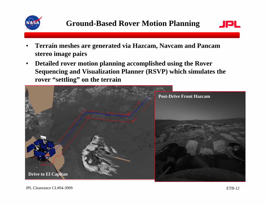
Ground-Based Rover Motion Planning
• Terrain meshes are generated via Hazcam, Navcam and Pancamstereo image pairs
• Detailed rover motion planning accomplished using the Rover Sequencing and Visualization Planner (RSVP) which simulates the rover “settling” on the terrain
Drive to El Capitan
Post-Drive Front Hazcam
ETB-13JPL Cleareance CL#04-3909
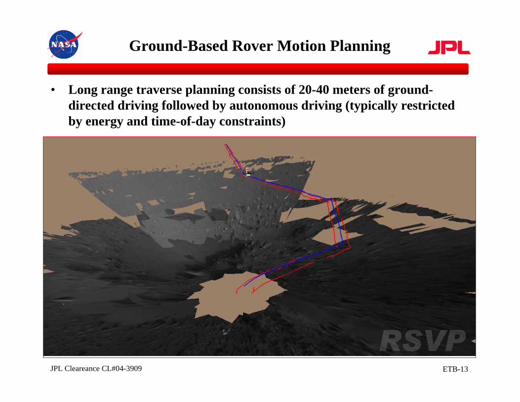
Ground-Based Rover Motion Planning
• Long range traverse planning consists of 20-40 meters of ground-directed driving followed by autonomous driving (typically restricted by energy and time-of-day constraints)
Drive to El Capitan
ETB-14JPL Cleareance CL#04-3909
Ground-Based Rover Motion Planning
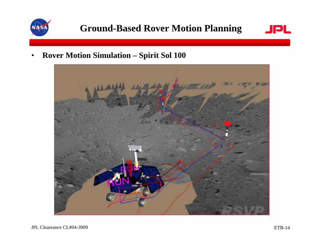
• Rover Motion Simulation – Spirit Sol 100
Drive to El Capitan
ETB-15JPL Cleareance CL#04-3909
Ground-Based Rover Motion Planning
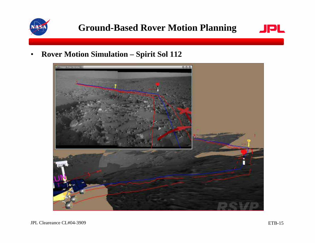
• Rover Motion Simulation – Spirit Sol 112
Drive to El Capitan
ETB-16JPL Cleareance CL#04-3909
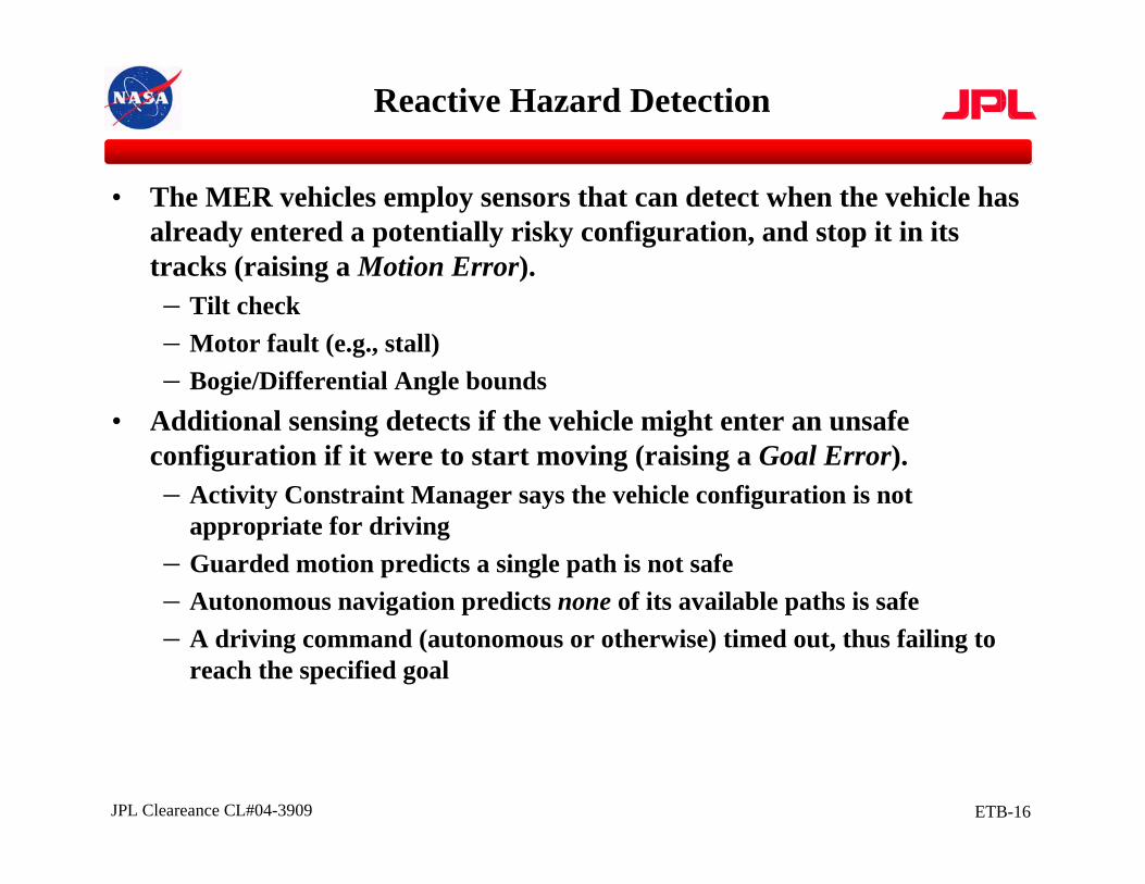
• The MER vehicles employ sensors that can detect when the vehicle has already entered a potentially risky configuration, and stop it in its tracks (raising a Motion Error).– Tilt check– Motor fault (e.g., stall)– Bogie/Differential Angle bounds
• Additional sensing detects if the vehicle might enter an unsafe configuration if it were to start moving (raising a Goal Error).– Activity Constraint Manager says the vehicle configuration is not
appropriate for driving– Guarded motion predicts a single path is not safe– Autonomous navigation predicts none of its available paths is safe– A driving command (autonomous or otherwise) timed out, thus failing to
reach the specified goal
Reactive Hazard Detection
ETB-17JPL Cleareance CL#04-3909
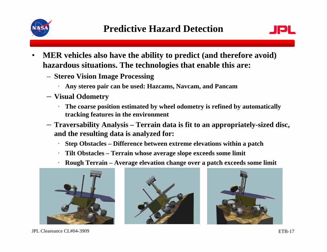
• MER vehicles also have the ability to predict (and therefore avoid) hazardous situations. The technologies that enable this are:
– Stereo Vision Image Processing· Any stereo pair can be used: Hazcams, Navcam, and Pancam
– Visual Odometry· The coarse position estimated by wheel odometry is refined by automatically
tracking features in the environment– Traversability Analysis – Terrain data is fit to an appropriately-sized disc,
and the resulting data is analyzed for:· Step Obstacles – Difference between extreme elevations within a patch· Tilt Obstacles – Terrain whose average slope exceeds some limit· Rough Terrain – Average elevation change over a patch exceeds some limit
Predictive Hazard Detection
ETB-18JPL Cleareance CL#04-3909
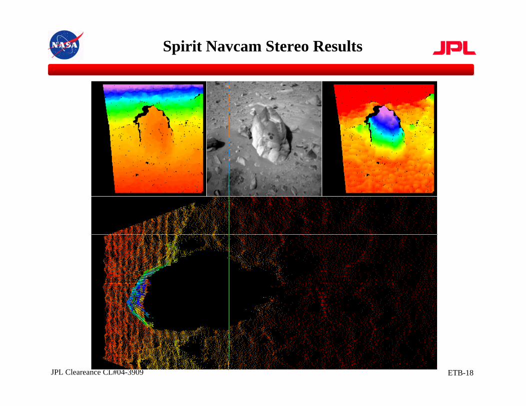
Spirit Navcam Stereo Results
ETB-19JPL Cleareance CL#04-3909
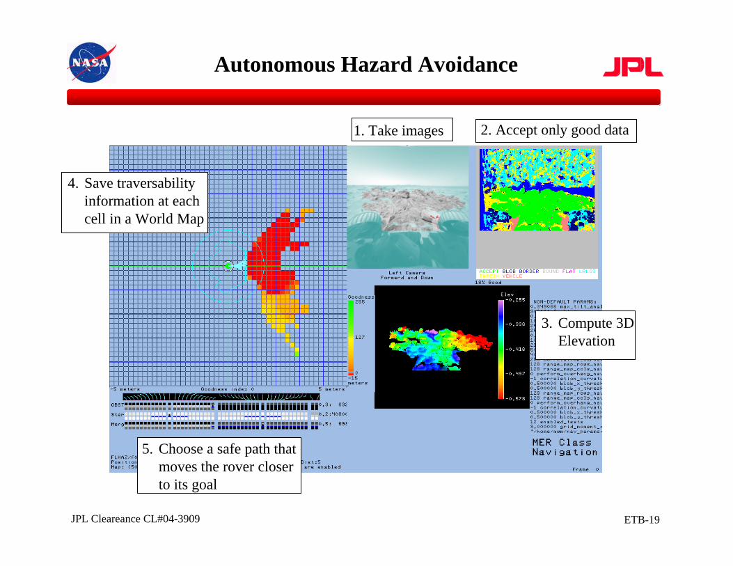
1. Take images 2. Accept only good data
3. Compute 3DElevation
4. Save traversabilityinformation at each cell in a World Map
5. Choose a safe path thatmoves the rover closerto its goal
Autonomous Hazard Avoidance
ETB-20JPL Cleareance CL#04-3909
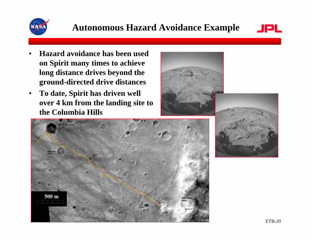
• Hazard avoidance has been used on Spirit many times to achieve long distance drives beyond the ground-directed drive distances
• To date, Spirit has driven well over 4 km from the landing site to the Columbia Hills
Autonomous Hazard Avoidance Example
ETB-21JPL Cleareance CL#04-3909
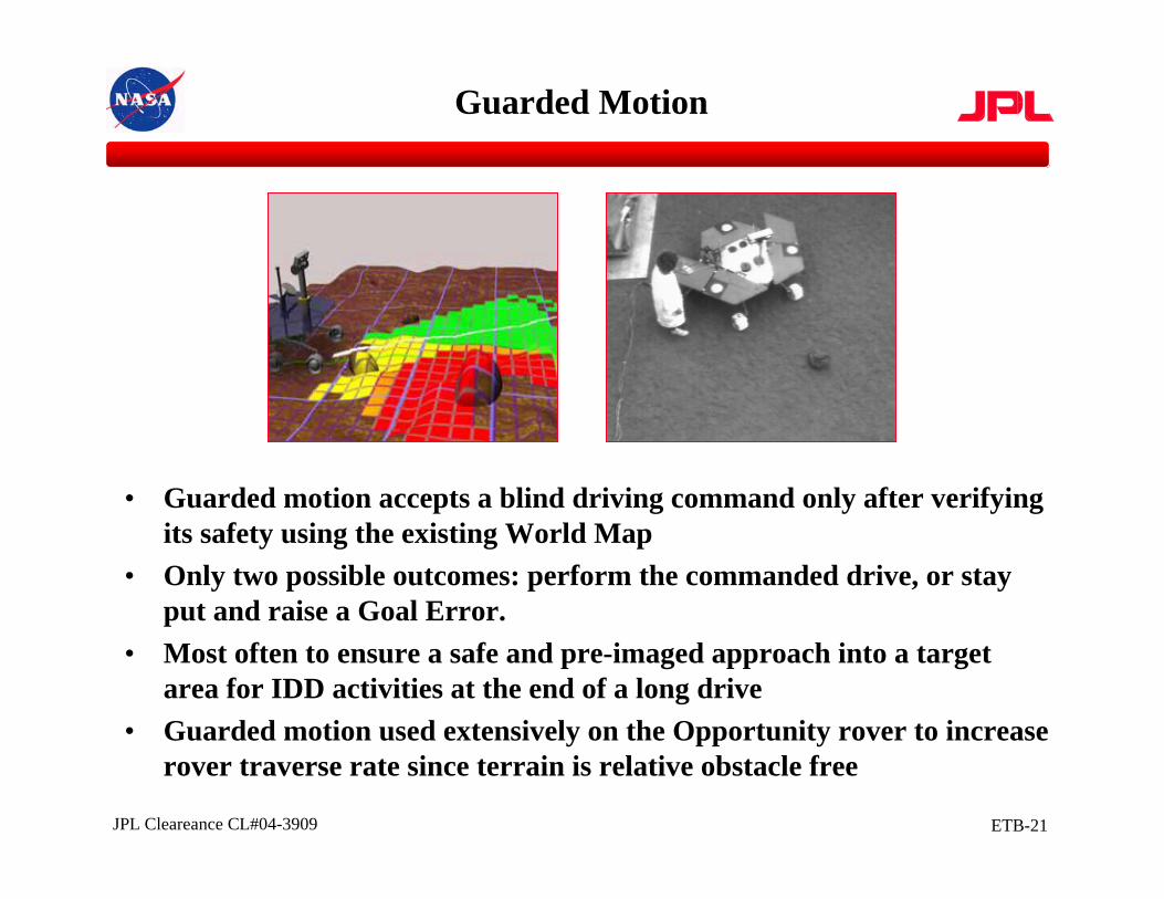
• Guarded motion accepts a blind driving command only after verifying its safety using the existing World Map
• Only two possible outcomes: perform the commanded drive, or stayput and raise a Goal Error.
• Most often to ensure a safe and pre-imaged approach into a target area for IDD activities at the end of a long drive
• Guarded motion used extensively on the Opportunity rover to increase rover traverse rate since terrain is relative obstacle free
Guarded Motion
ETB-22JPL Cleareance CL#04-3909
Ground-Based Manipulation Motion Planning
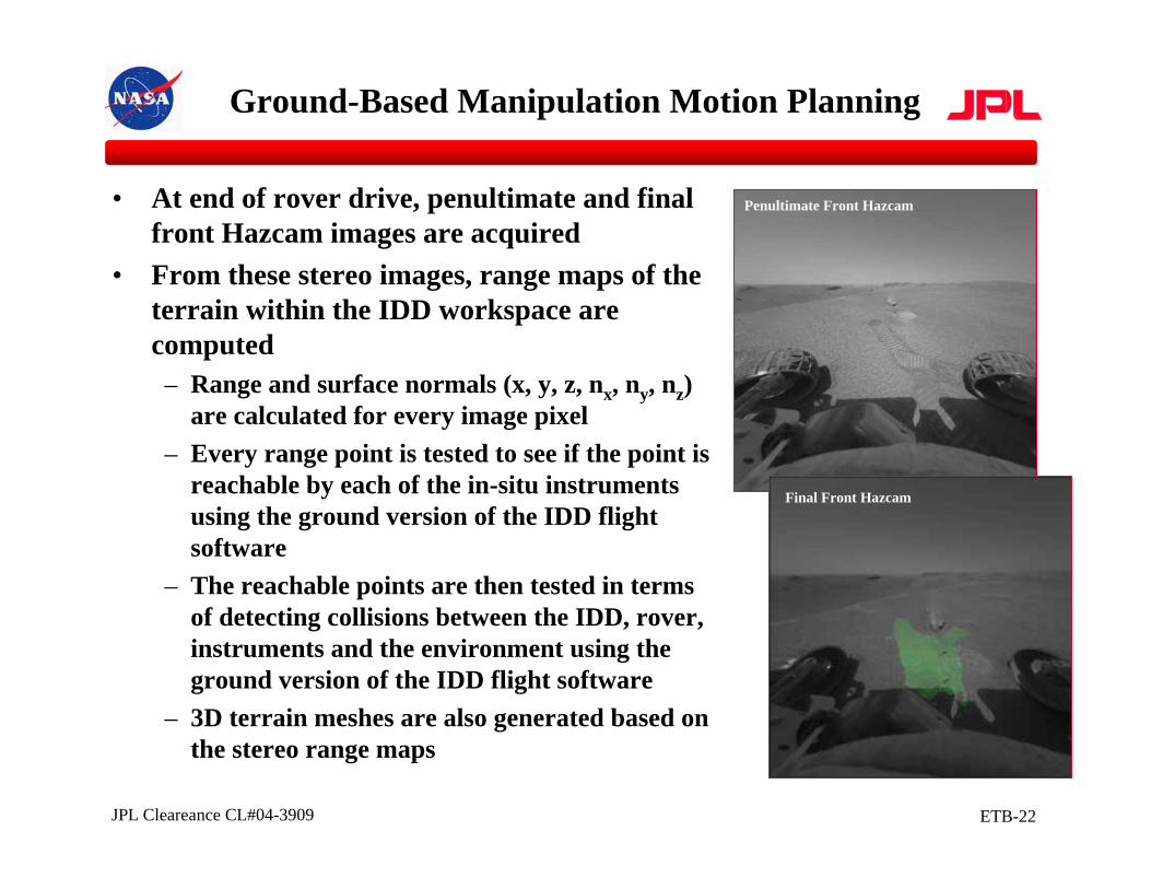
• At end of rover drive, penultimate and final front Hazcam images are acquired
• From these stereo images, range maps of the terrain within the IDD workspace are computed– Range and surface normals (x, y, z, nx, ny, nz)
are calculated for every image pixel– Every range point is tested to see if the point is
reachable by each of the in-situ instruments using the ground version of the IDD flight software
– The reachable points are then tested in terms of detecting collisions between the IDD, rover, instruments and the environment using the ground version of the IDD flight software
– 3D terrain meshes are also generated based on the stereo range maps
Penultimate Front Hazcam
Final Front Hazcam
ETB-23JPL Cleareance CL#04-3909
Ground-Based Manipulation Motion Planning
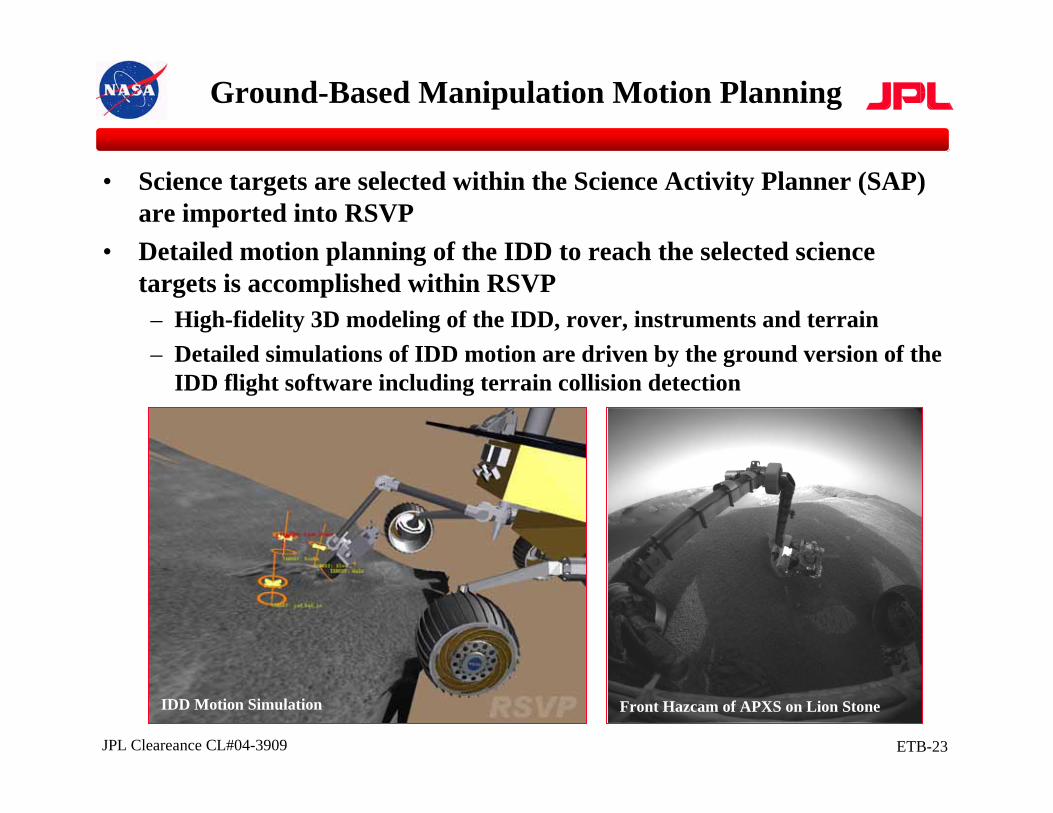
• Science targets are selected within the Science Activity Planner (SAP) are imported into RSVP
• Detailed motion planning of the IDD to reach the selected science targets is accomplished within RSVP– High-fidelity 3D modeling of the IDD, rover, instruments and terrain– Detailed simulations of IDD motion are driven by the ground version of the
IDD flight software including terrain collision detection
IDD Motion Simulation Front Hazcam of APXS on Lion Stone
ETB-24JPL Cleareance CL#04-3909
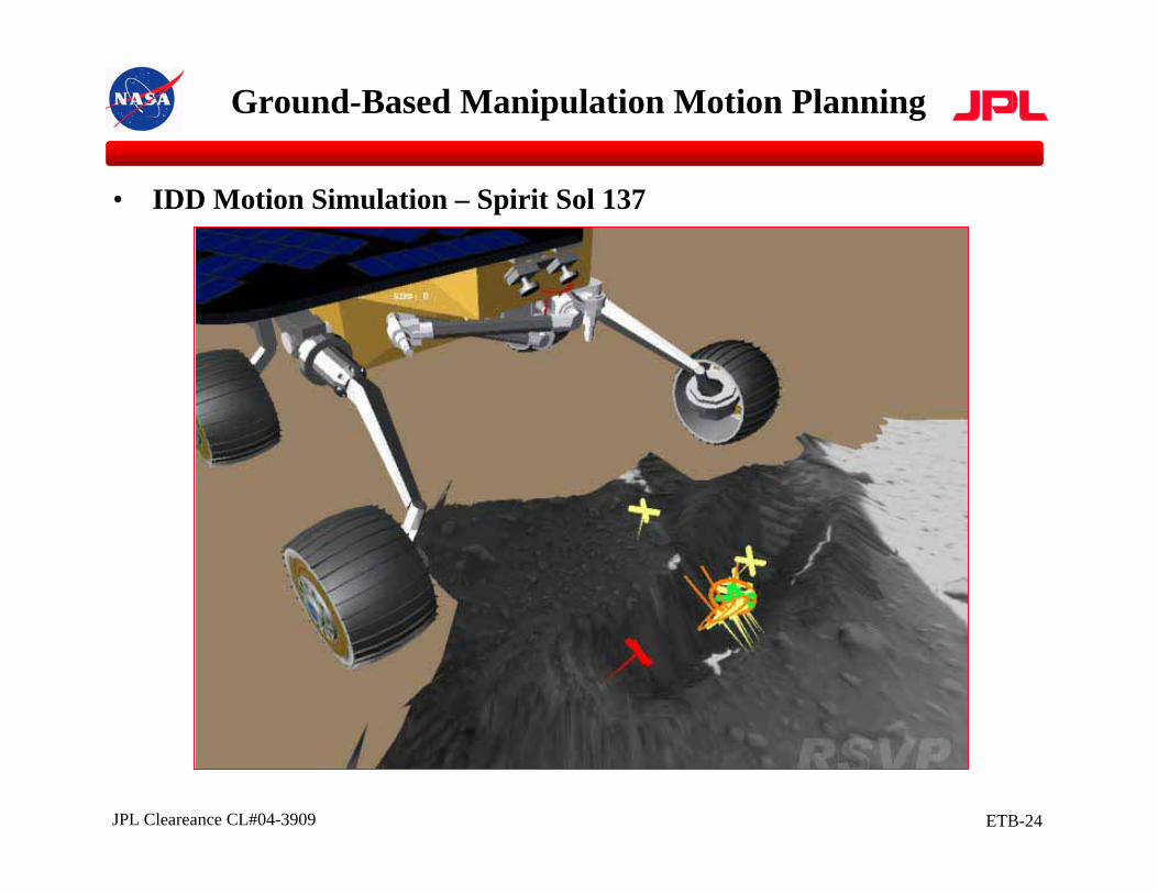
Ground-Based Manipulation Motion Planning
• IDD Motion Simulation – Spirit Sol 137
ETB-25JPL Cleareance CL#04-3909
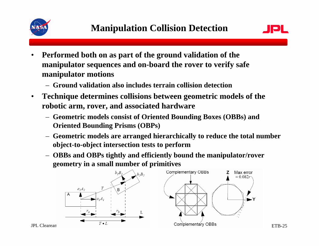
Manipulation Collision Detection
• Performed both on as part of the ground validation of the manipulator sequences and on-board the rover to verify safe manipulator motions– Ground validation also includes terrain collision detection
• Technique determines collisions between geometric models of the robotic arm, rover, and associated hardware– Geometric models consist of Oriented Bounding Boxes (OBBs) and
Oriented Bounding Prisms (OBPs)– Geometric models are arranged hierarchically to reduce the total number
object-to-object intersection tests to perform– OBBs and OBPs tightly and efficiently bound the manipulator/rover
geometry in a small number of primitives
ETB-26JPL Cleareance CL#04-3909
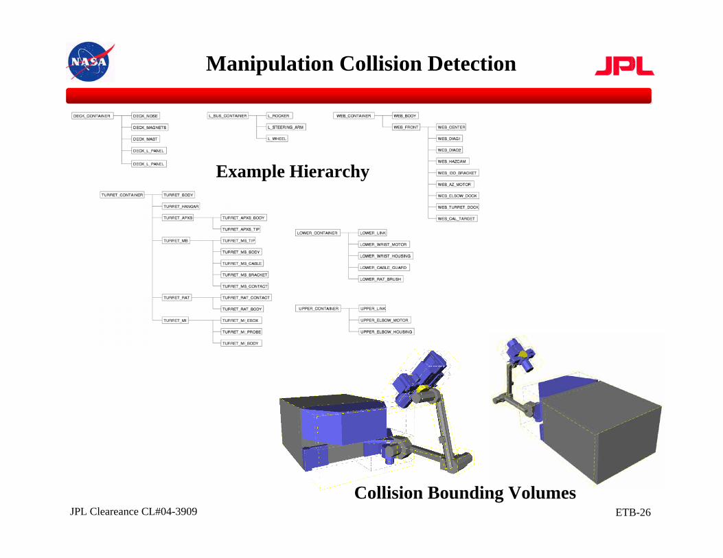
Manipulation Collision Detection
Example Hierarchy
Collision Bounding Volumes
ETB-27JPL Cleareance CL#04-3909
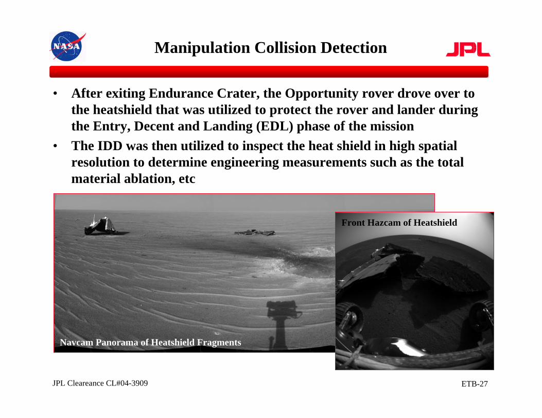
• After exiting Endurance Crater, the Opportunity rover drove over to the heatshield that was utilized to protect the rover and lander during the Entry, Decent and Landing (EDL) phase of the mission
• The IDD was then utilized to inspect the heat shield in high spatial resolution to determine engineering measurements such as the total material ablation, etc
Manipulation Collision Detection
Navcam Panorama of Heatshield Fragments
Front Hazcam of Heatshield
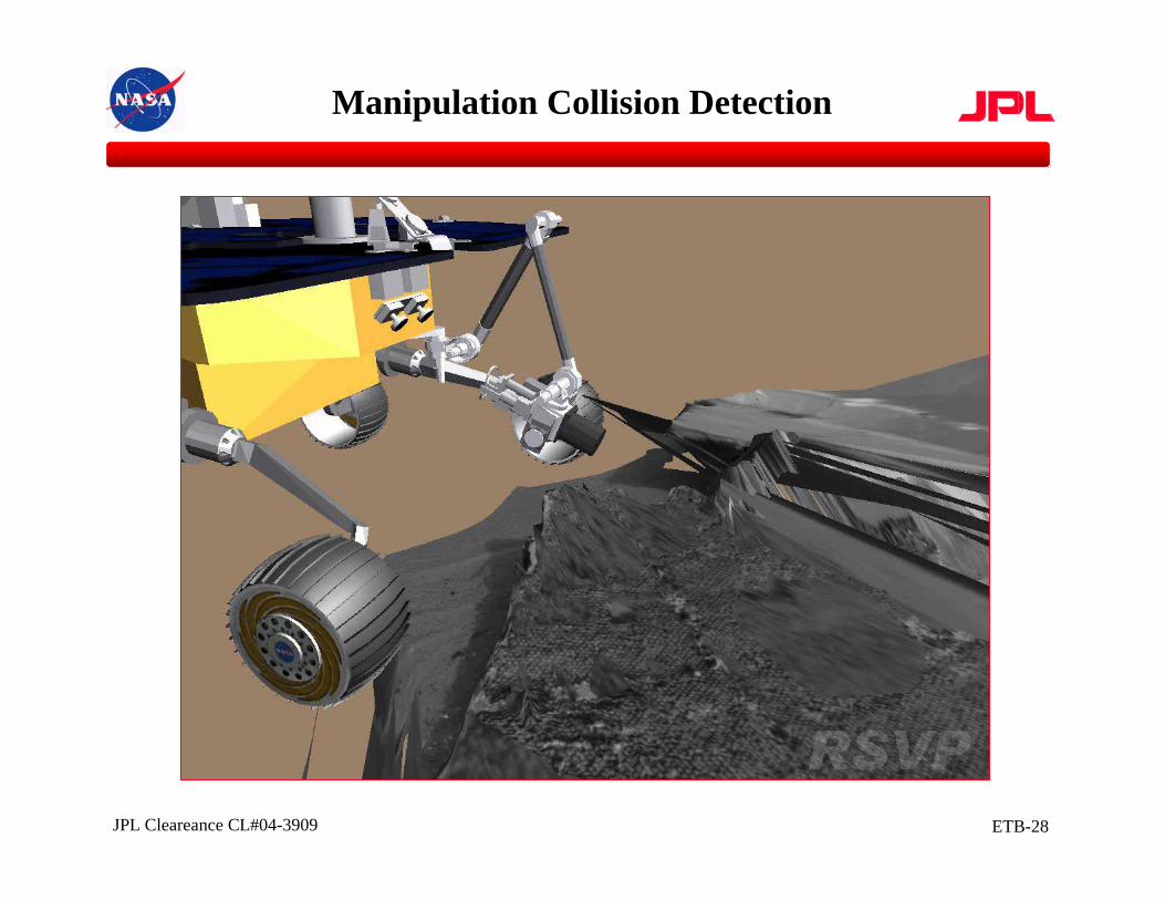
ETB-28JPL Cleareance CL#04-3909
Manipulation Collision Detection
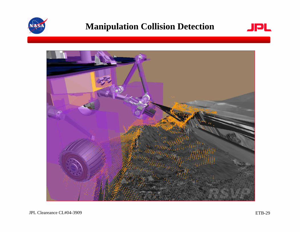
ETB-29JPL Cleareance CL#04-3909
Manipulation Collision Detection
ETB-30JPL Cleareance CL#04-3909
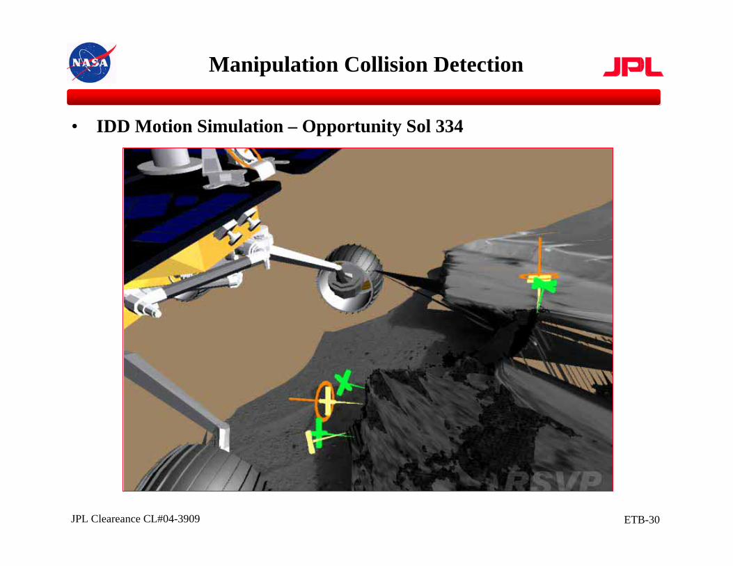
• IDD Motion Simulation – Opportunity Sol 334
Manipulation Collision Detection
ETB-31JPL Cleareance CL#04-3909
Conclusions
• The Mars Exploration Rovers have utilized a combination of both ground-based (sequenced) and on-board (autonomous) motion planning techniques– Rover motion planning makes use of a virtual terrain environment coupled
with estimated wheel/soil terrain interactions to sequence rover with respect to desired science targets
– Long rover traverses are autonomous with on-board path planning around detected obstacles
– Robotic arm motion planning is primarily ground directed with on-board collision detection
– Manipulator sequences are validated through a high-fidelity simulation of the flight software that is used to control the robotic arm
• Future work includes including terrain collision detection on-board as part of the flight software and utilizing advanced motion planning techniques to perform automatic instrument placement activities
ETB-32JPL Cleareance CL#04-3909http://marsrovers.jpl.nasa.gov
Join the Adventure!