Embed Size (px)
Citation preview

Motor-CAD Links to SPEED
Mircea Popescu & Dave Staton
Motor Design Ltd
March 2012
2 2
Topics
• Motor Design Ltd • Motor-CAD software and other design tools marketed by
MDL • The SPEED Thermal Models • SPEED and Motor-CAD together • Automatically links from SPEED to Motor-CAD and Motor-
CAD to SPEED • Calibration of the SPEED thermal model using Motor-CAD
3
Motor Design Ltd
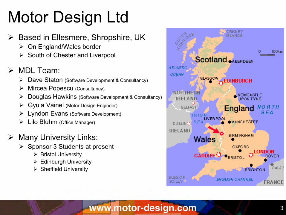
Based in Ellesmere, Shropshire, UK On England/Wales border South of Chester and Liverpool
MDL Team: Dave Staton (Software Development & Consultancy)
Mircea Popescu (Consultancy)
Douglas Hawkins (Software Development & Consultancy)
Gyula Vainel (Motor Design Engineer)
Lyndon Evans (Software Development)
Lilo Bluhm (Office Manager)
Many University Links: Sponsor 3 Students at present
Bristol University Edinburgh University Sheffield University
4
Motor Design Ltd (MDL) set up in 1998 to develop software for design of electric
motors and provide motor design consulting and training
distribute SPEED, Motor-CAD, FLUX and PORTUNUS software complete package for electric motor and drive simulation
software package also used in our consulting work
developed the following software products: Motor-CAD – Analytical Network Software for Thermal Analysis of
Electric Machines
PORTUNUS Thermal Library - system simulation software for thermal simulation of any device
Other software currently under development to make the design process easier for the user (link to SPEED software): Motor-LAB developed with EngD student at Bristol – new software to optimise
design for full torque/speed envelope rather than a single torque/speed
Motor-FLOW to allow the user to automate SPEED/Motor-CAD calculations without having to write a computer script (draw a flow diagram instead)
Eff-MAP model run in Motor-FLOW to calculate and plot efficiency maps
5 5
Motor Design Software Suite • SPEED
• Motor-CAD
• FLUX
• PORTUNUS
• STAR-CCM+
the worlds leading analytical software package for the design of electric motors (with integrated FEA)
unique analytical software package for the thermal analysis of electric motors
SPEED & Motor-CAD’s analytical based algorithms give instantaneous calculation speeds and allow 'what-if' analysis in real time
finite element software well adapted for accurate electromagnetic simulation of electric motors
system simulator developed for the calculation of drives and mechatronic systems
– thermal library allows thermal analysis of almost any device with mixed electrical/mechanical/thermal simulation
now have STAR-CCM+ for advanced thermal analysis using CFD
6 6
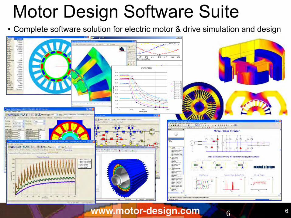
Motor Design Software Suite • Complete software solution for electric motor & drive simulation and design
IPM T/S PC-BDC
0.00
5.00
10.00
15.00
20.00
25.00
30.00
35.00
40.00
45.00
50.00
0 2500 5000 7500 10000
SPEED [RPM]
To
rqu
e [
Nm
]
T[gamma=0]
T[gamma=10]
T[gamma=20]
T[gamma=30]
T[gamma=40]
T[gamma=50]
T[gamma=60]
T[gamma=70]
T[gamma=80]
7
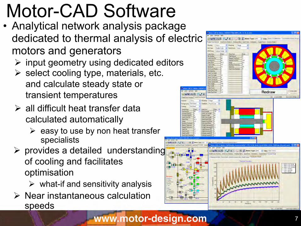
Motor-CAD Software • Analytical network analysis package
dedicated to thermal analysis of electric motors and generators input geometry using dedicated editors select cooling type, materials, etc.
and calculate steady state or transient temperatures
all difficult heat transfer data calculated automatically easy to use by non heat transfer
specialists
provides a detailed understanding of cooling and facilitates optimisation what-if and sensitivity analysis
Near instantaneous calculation speeds
8
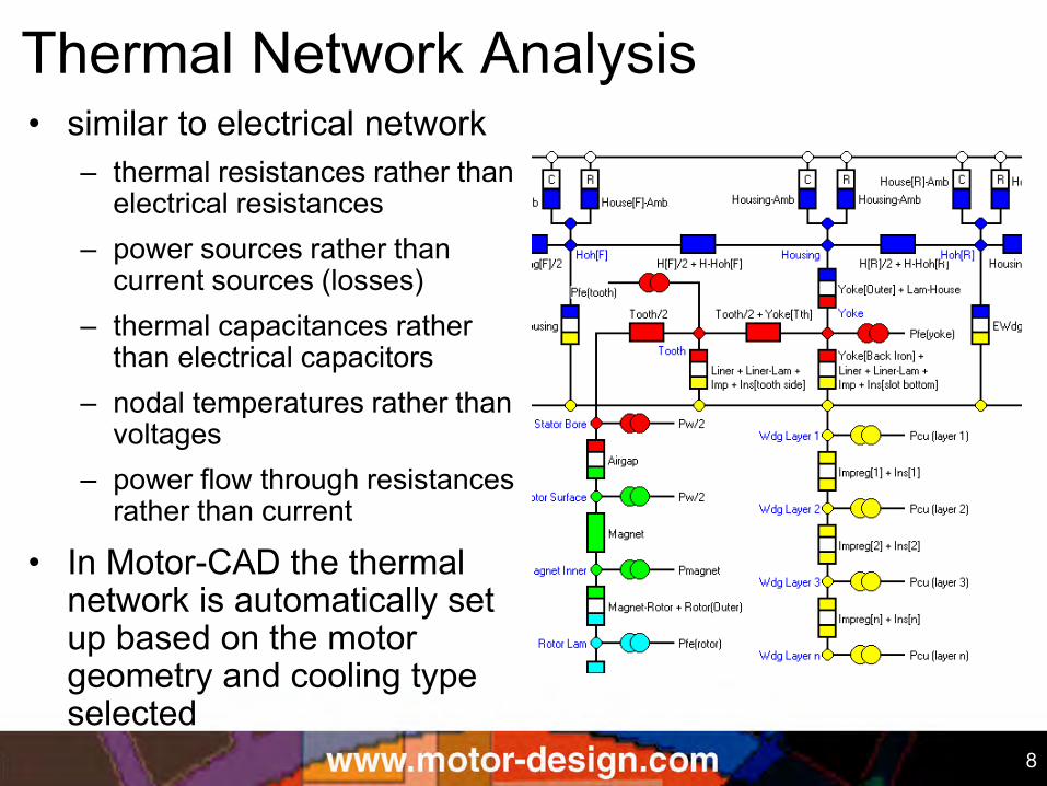
Thermal Network Analysis • similar to electrical network
– thermal resistances rather than electrical resistances
– power sources rather than current sources (losses)
– thermal capacitances rather than electrical capacitors
– nodal temperatures rather than voltages
– power flow through resistances rather than current
• In Motor-CAD the thermal network is automatically set up based on the motor geometry and cooling type selected

9
Motor-CAD Motor Types
• Brushless Permanent Magnet
• Induction • 3ph and single phase
• Switched Reluctance
10
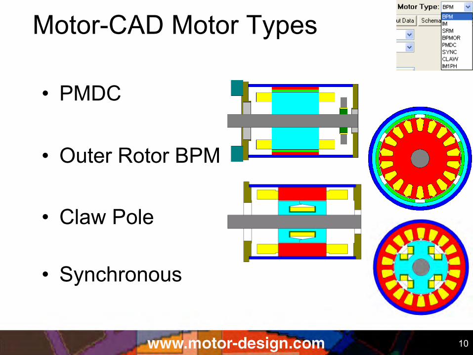
Motor-CAD Motor Types
• Outer Rotor BPM
• Claw Pole
• Synchronous
• PMDC
11
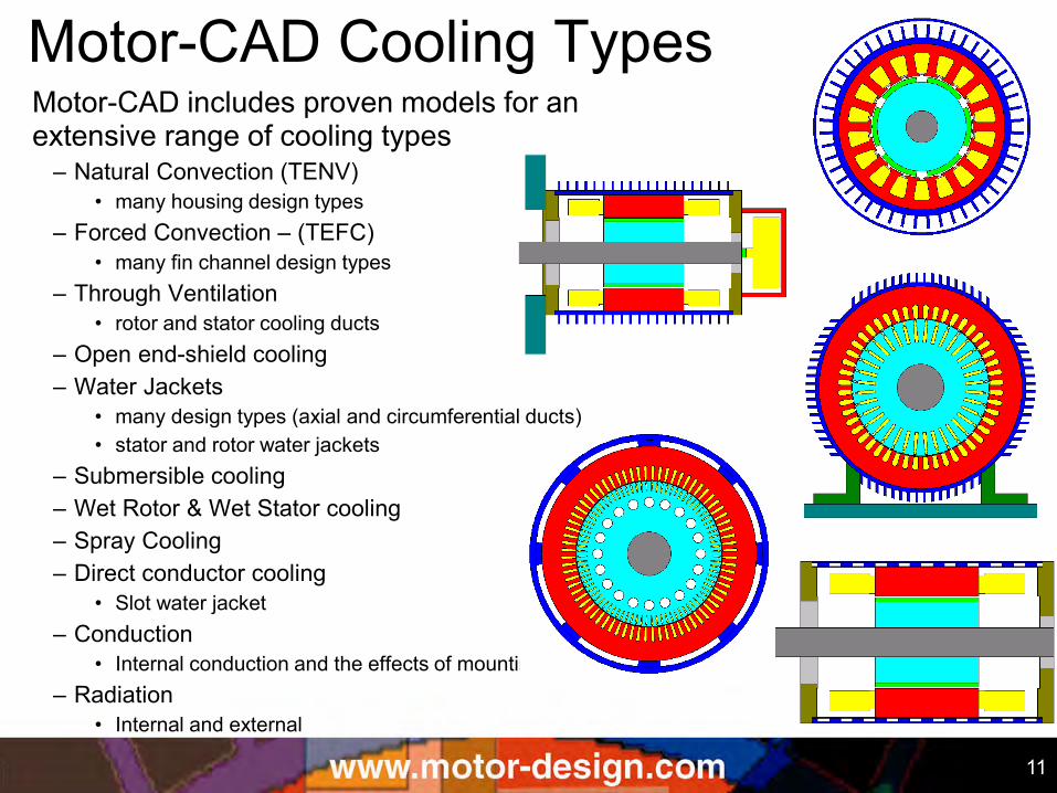
Motor-CAD Cooling Types Motor-CAD includes proven models for an extensive range of cooling types
– Natural Convection (TENV) • many housing design types
– Forced Convection – (TEFC) • many fin channel design types
– Through Ventilation • rotor and stator cooling ducts
– Open end-shield cooling – Water Jackets
• many design types (axial and circumferential ducts) • stator and rotor water jackets
– Submersible cooling – Wet Rotor & Wet Stator cooling – Spray Cooling – Direct conductor cooling
• Slot water jacket – Conduction
• Internal conduction and the effects of mounting – Radiation
• Internal and external
12
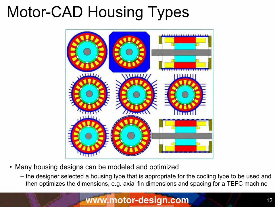
Motor-CAD Housing Types
• Many housing designs can be modeled and optimized – the designer selected a housing type that is appropriate for the cooling type to be used and
then optimizes the dimensions, e.g. axial fin dimensions and spacing for a TEFC machine
13
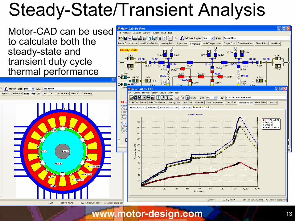
Steady-State/Transient Analysis Motor-CAD can be used to calculate both the steady-state and transient duty cycle thermal performance
14
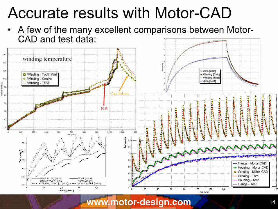
Accurate results with Motor-CAD • A few of the many excellent comparisons between Motor-
CAD and test data:
15
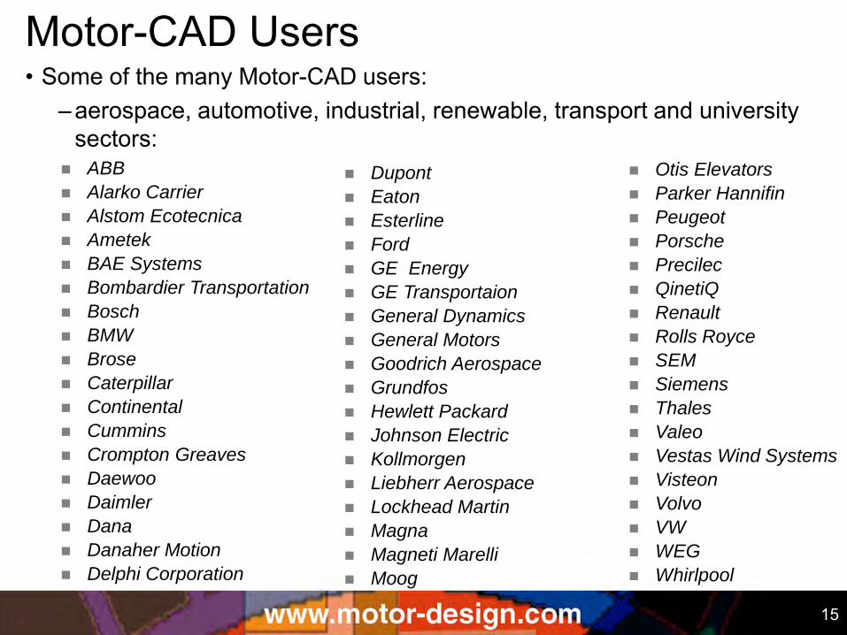
Motor-CAD Users • Some of the many Motor-CAD users:
–aerospace, automotive, industrial, renewable, transport and university sectors:
ABB
Alarko Carrier
Alstom Ecotecnica
Ametek
BAE Systems
Bombardier Transportation
Bosch
BMW
Brose
Caterpillar
Continental
Cummins
Crompton Greaves
Daewoo
Daimler
Dana
Danaher Motion
Delphi Corporation
Otis Elevators
Parker Hannifin
Peugeot
Porsche
Precilec
QinetiQ
Renault
Rolls Royce
SEM
Siemens
Thales
Valeo
Vestas Wind Systems
Visteon
Volvo
VW
WEG
Whirlpool
Dupont
Eaton
Esterline
Ford
GE Energy
GE Transportaion
General Dynamics
General Motors
Goodrich Aerospace
Grundfos
Hewlett Packard
Johnson Electric
Kollmorgen
Liebherr Aerospace
Lockhead Martin
Magna
Magneti Marelli
Moog
16
SPEED & Motor-CAD Together • SPEED is predominantly used for electromagnetic
performance prediction – very simple thermal network models built into software but
require calibration
• Motor-CAD has sophisticated thermal models that require the user to have NO knowledge of heat transfer
• To predict the performance accurately both packages can be used together
– losses are critically dependent on temperature – temperatures are critically dependent on loss
• Automated links ease the transfer of geometry, loss and temperature data between packages
17
SPEED & Motor-CAD Together • Both SPEED and Motor-CAD are analytical analysis
packages providing instantaneous calculation speeds • Most Importantly - the user just needs to input the geometry
and selects a few winding/drive/material options and then all the difficult magnetic and heat transfer parameters are calculated automatically – User need not be a magnetic or thermal expert – Also ideal for training
• Both SPEED and Motor-CAD are excellent for carrying out “What If” calculations – direct access to physical input parameters such as “Tooth
Width”, “Airgap”, “Liner Thickness”, “Turns Per Coil”, “Liner Thermal Conductivity”, etc.
– direct access to physical output parameters such as “Shaft Torque”, “Copper Loss”, “Winding Average Temperature”, “Winding Hotspot Temperature”, “Magnet Temperature”, etc.
18
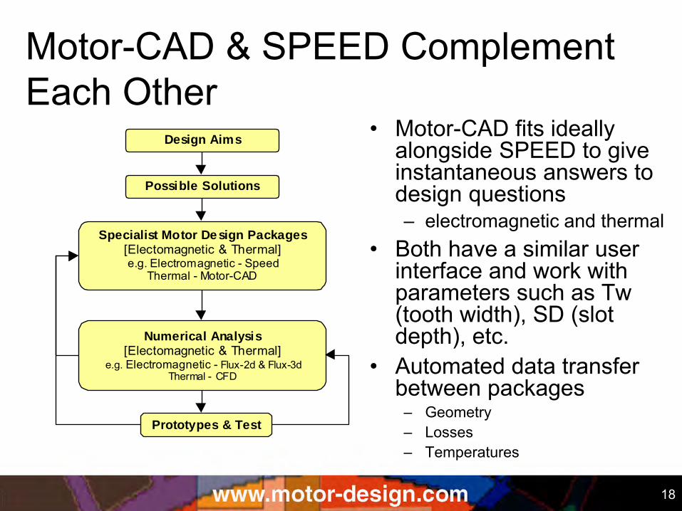
Motor-CAD & SPEED Complement Each Other
Design Aims
Possible Solutions
Specialist Motor Design Packages [Electomagnetic & Thermal] e.g. Electromagnetic - Speed
Thermal - Motor-CAD
Prototypes & Test
Numerical Analysis [Electomagnetic & Thermal]
e.g. Electromagnetic - Flux-2d & Flux-3d Thermal - CFD
• Motor-CAD fits ideally alongside SPEED to give instantaneous answers to design questions – electromagnetic and thermal
• Both have a similar user interface and work with parameters such as Tw (tooth width), SD (slot depth), etc.
• Automated data transfer between packages
– Geometry – Losses – Temperatures
19
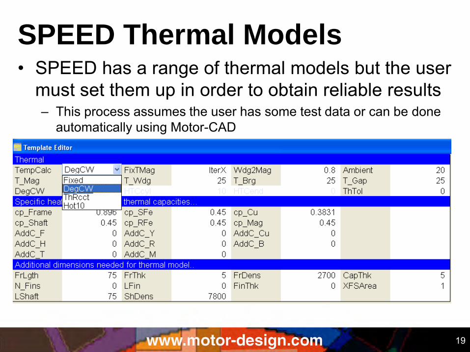
SPEED Thermal Models • SPEED has a range of thermal models but the user
must set them up in order to obtain reliable results – This process assumes the user has some test data or can be done
automatically using Motor-CAD
20
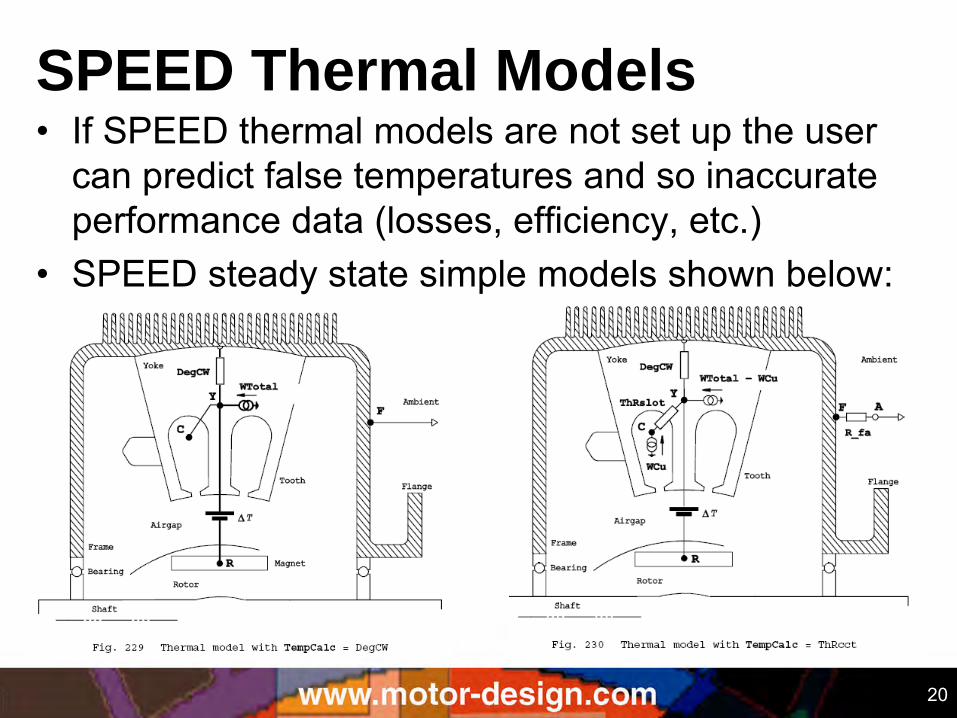
SPEED Thermal Models • If SPEED thermal models are not set up the user
can predict false temperatures and so inaccurate performance data (losses, efficiency, etc.)
• SPEED steady state simple models shown below:
21
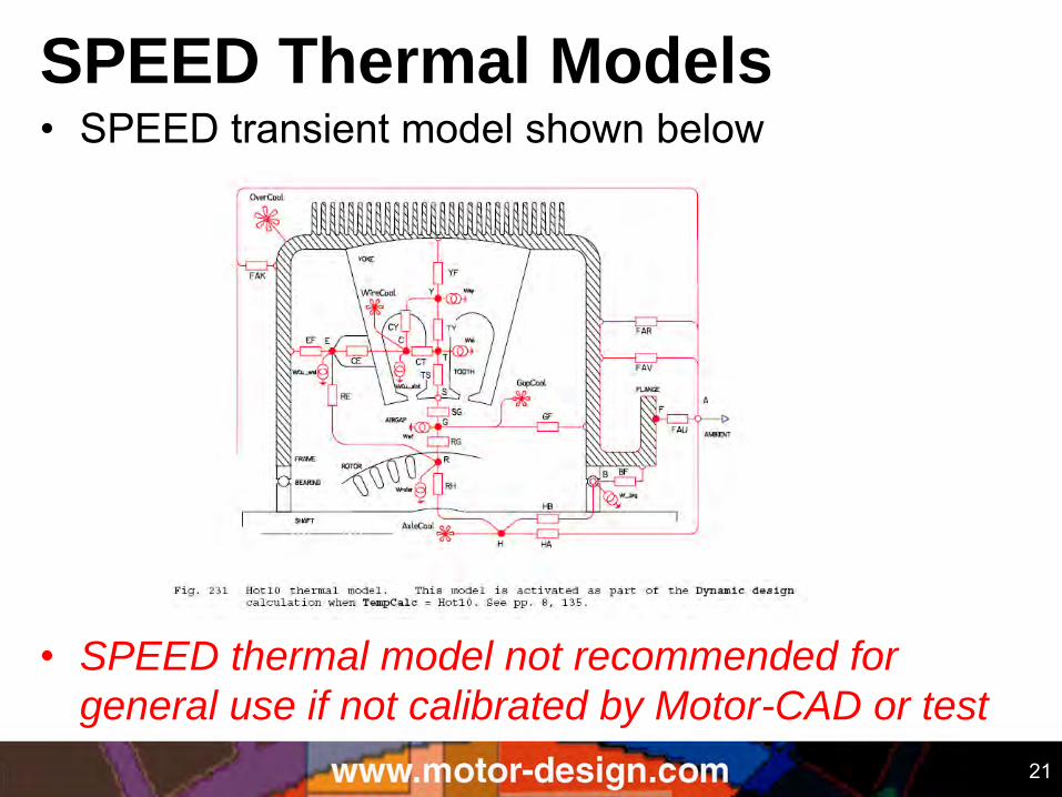
SPEED Thermal Models • SPEED transient model shown below
• SPEED thermal model not recommended for
general use if not calibrated by Motor-CAD or test
22
SPEED/Motor-CAD Link History • The original SPEED/Motor-CAD Links were initiated by a call
from Motor-CAD to SPEED to import geometry and losses and pass back temperatures
– first released Motor-CAD v1.6 (October 2002)
• After this proved successful we developed direct links from SPEED to Motor-CAD
– Termed GoTAR – Go Thermal Analysis and Return
– ActiveX call to Motor-CAD with most of linkage code implemented in Motor-CAD
– Facilitates automated calibration of SPEED thermal models
User has full control of this calibration process
– First released in 2007
23
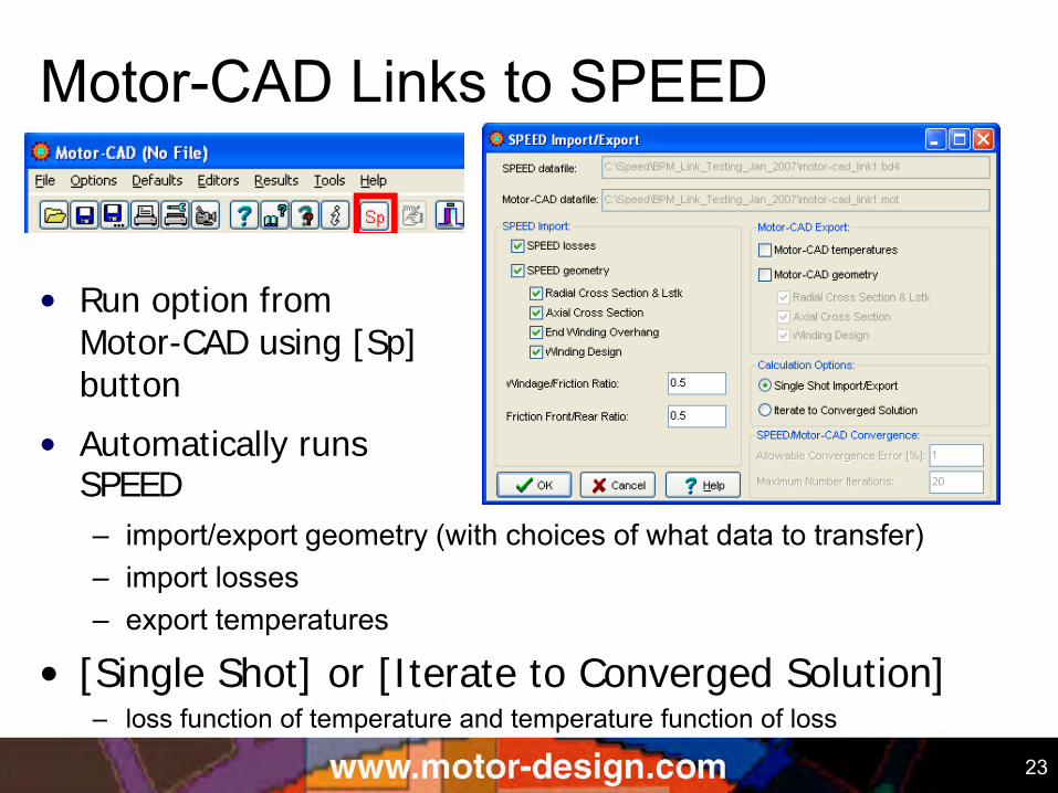
Motor-CAD Links to SPEED
– import/export geometry (with choices of what data to transfer) – import losses – export temperatures
• [Single Shot] or [Iterate to Converged Solution] – loss function of temperature and temperature function of loss
• Run option from Motor-CAD using [Sp] button
• Automatically runs SPEED
24
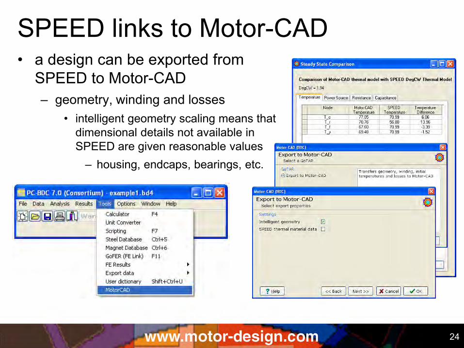
SPEED links to Motor-CAD • a design can be exported from
SPEED to Motor-CAD – geometry, winding and losses
• intelligent geometry scaling means that dimensional details not available in SPEED are given reasonable values
– housing, endcaps, bearings, etc.
25
SPEED/Motor-CAD Data Links Typical Procedure: • import geometry, winding and losses from SPEED with
temperatures of winding and magnets at expected values • set geometric data for non electromagnetic components
such as the housing and bearings • set the cooling type and choose materials
– default materials can often be used initially with fine selection later
• calculate the temperatures and compare with expectations • [Iterate to Converged Solution] to make both models use
the same loss and temperature data • can change both electromagnetic (SPEED) and thermal
(Motor-CAD) designs and try to optimise total solution
26
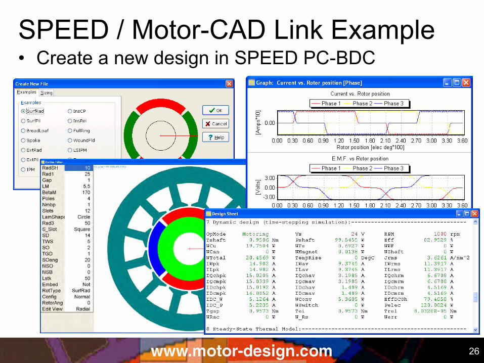
• Create a new design in SPEED PC-BDC SPEED / Motor-CAD Link Example
27
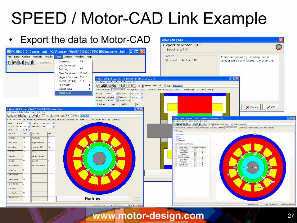
• Export the data to Motor-CAD
SPEED / Motor-CAD Link Example
28
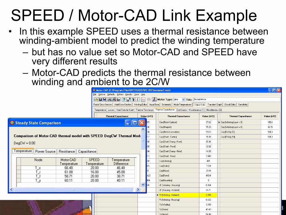
• In this example SPEED uses a thermal resistance between winding-ambient model to predict the winding temperature – but has no value set so Motor-CAD and SPEED have
very different results – Motor-CAD predicts the thermal resistance between
winding and ambient to be 2C/W
SPEED / Motor-CAD Link Example
29
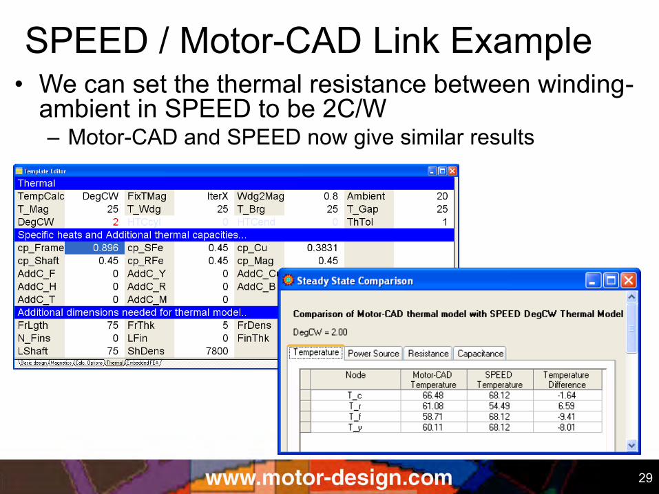
• We can set the thermal resistance between winding-ambient in SPEED to be 2C/W – Motor-CAD and SPEED now give similar results
SPEED / Motor-CAD Link Example
30
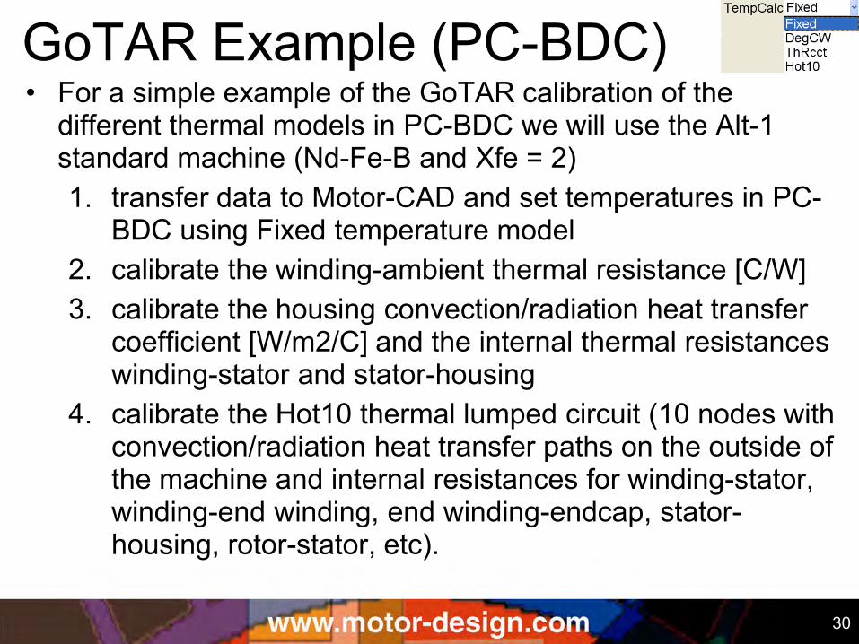
GoTAR Example (PC-BDC) • For a simple example of the GoTAR calibration of the
different thermal models in PC-BDC we will use the Alt-1 standard machine (Nd-Fe-B and Xfe = 2) 1. transfer data to Motor-CAD and set temperatures in PC-
BDC using Fixed temperature model 2. calibrate the winding-ambient thermal resistance [C/W] 3. calibrate the housing convection/radiation heat transfer
coefficient [W/m2/C] and the internal thermal resistances winding-stator and stator-housing
4. calibrate the Hot10 thermal lumped circuit (10 nodes with convection/radiation heat transfer paths on the outside of the machine and internal resistances for winding-stator, winding-end winding, end winding-endcap, stator-housing, rotor-stator, etc).
31
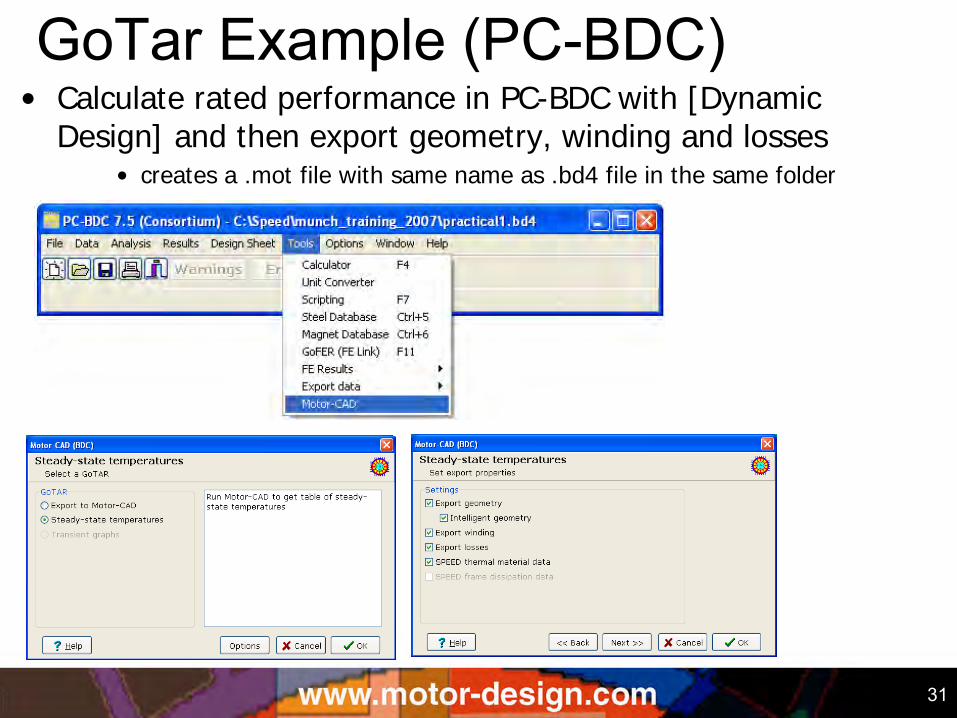
GoTar Example (PC-BDC) • Calculate rated performance in PC-BDC with [Dynamic
Design] and then export geometry, winding and losses • creates a .mot file with same name as .bd4 file in the same folder
32
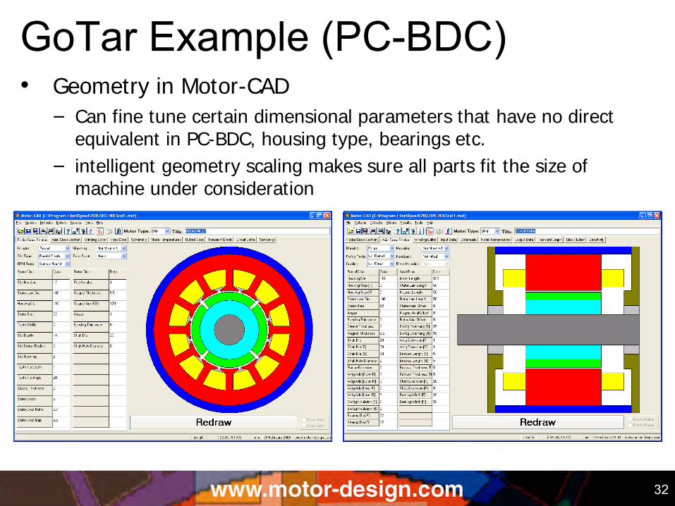
• Geometry in Motor-CAD
– Can fine tune certain dimensional parameters that have no direct equivalent in PC-BDC, housing type, bearings etc.
– intelligent geometry scaling makes sure all parts fit the size of machine under consideration
GoTar Example (PC-BDC)
33
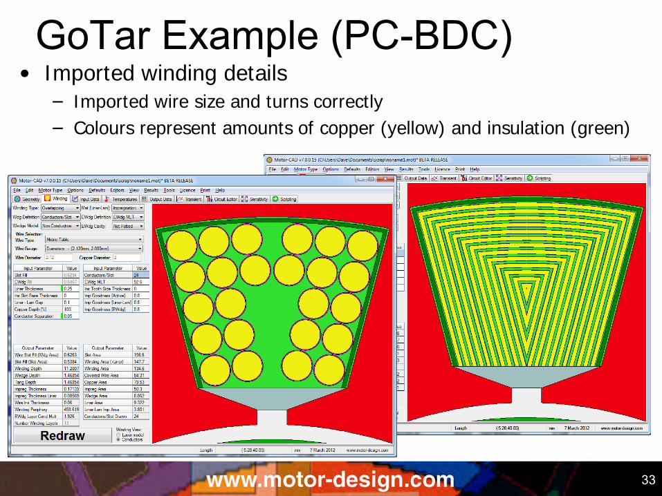
• Imported winding details
– Imported wire size and turns correctly
– Colours represent amounts of copper (yellow) and insulation (green)
GoTar Example (PC-BDC)
34
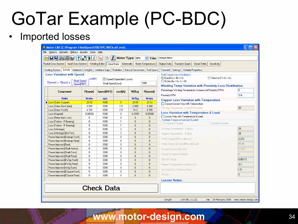
• Imported losses GoTar Example (PC-BDC)
35
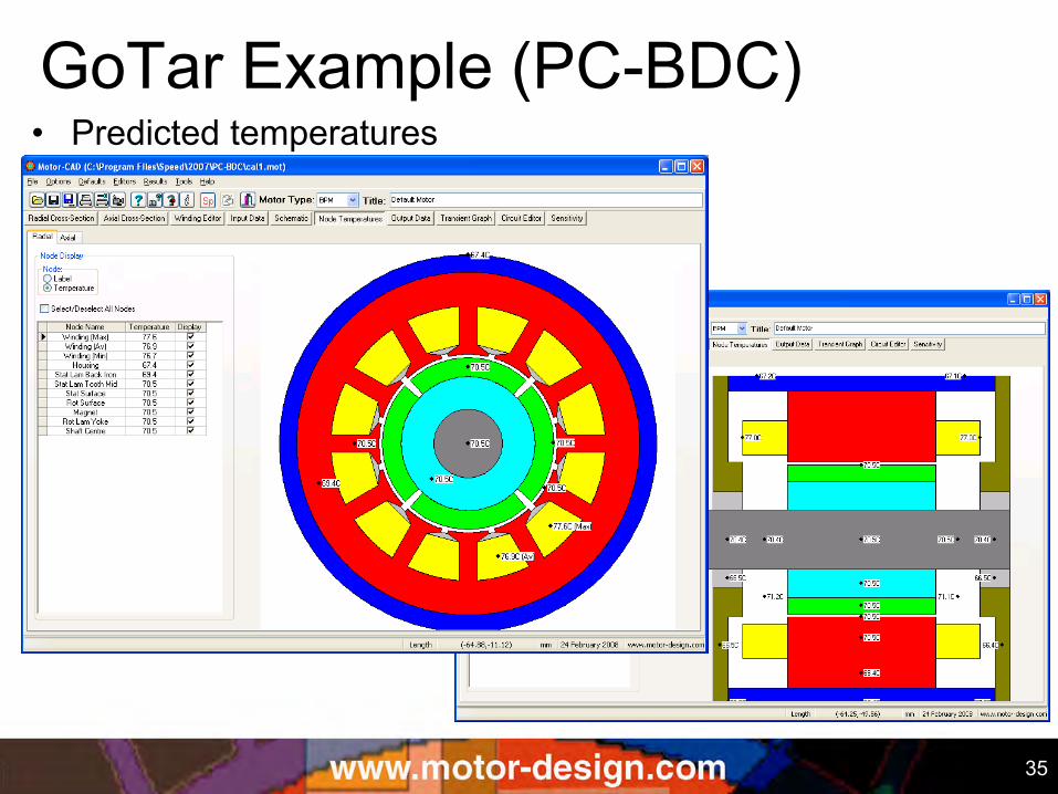
• Predicted temperatures GoTar Example (PC-BDC)
36
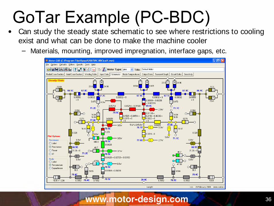
• Can study the steady state schematic to see where restrictions to cooling exist and what can be done to make the machine cooler
– Materials, mounting, improved impregnation, interface gaps, etc.
GoTar Example (PC-BDC)
37
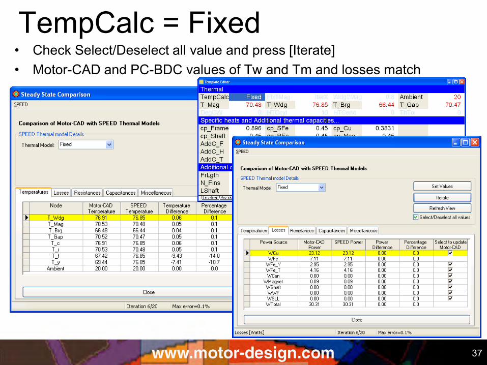
• Check Select/Deselect all value and press [Iterate] • Motor-CAD and PC-BDC values of Tw and Tm and losses match
TempCalc = Fixed
38
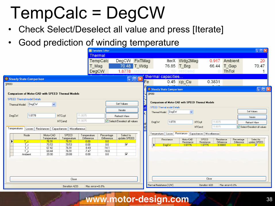
• Check Select/Deselect all value and press [Iterate] • Good prediction of winding temperature
TempCalc = DegCW
39
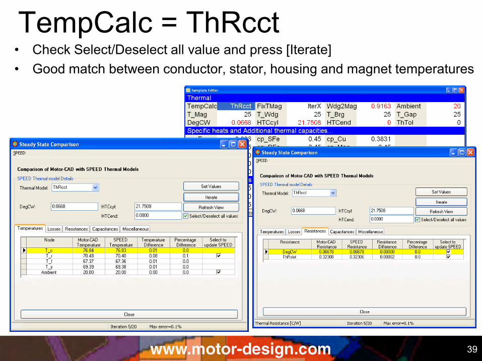
• Check Select/Deselect all value and press [Iterate] • Good match between conductor, stator, housing and magnet temperatures
TempCalc = ThRcct
40
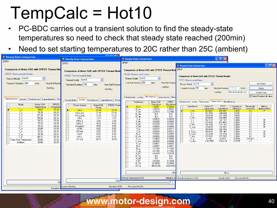
• PC-BDC carries out a transient solution to find the steady-state temperatures so need to check that steady state reached (200min)
• Need to set starting temperatures to 20C rather than 25C (ambient)
TempCalc = Hot10
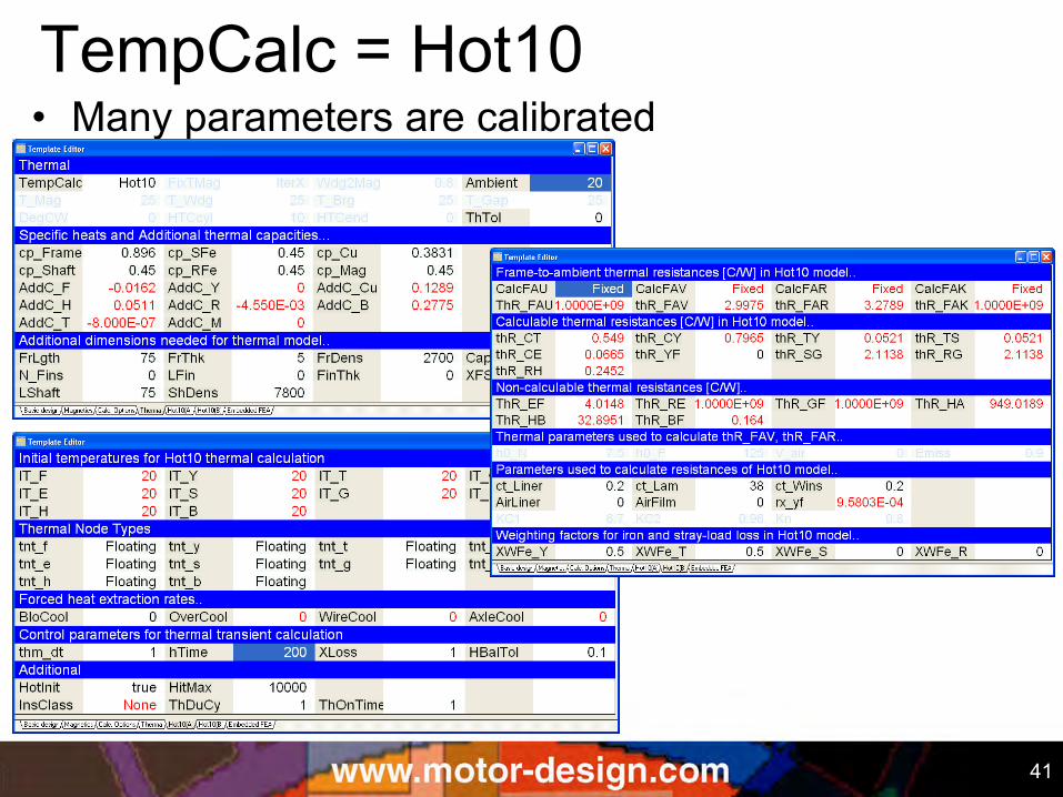
41
• Many parameters are calibrated TempCalc = Hot10
42
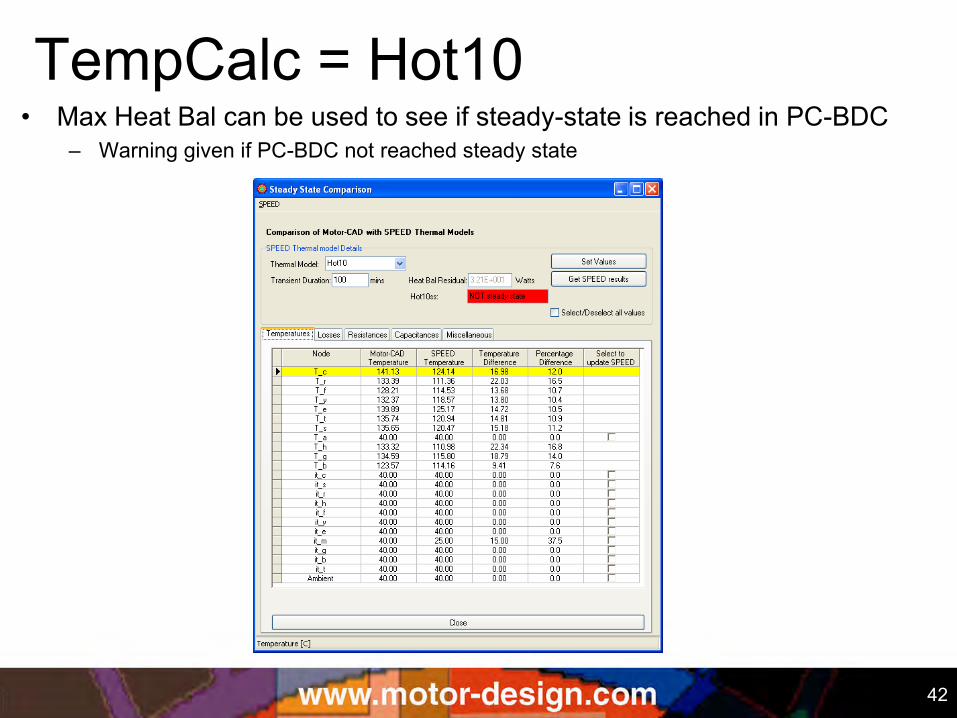
• Max Heat Bal can be used to see if steady-state is reached in PC-BDC – Warning given if PC-BDC not reached steady state
TempCalc = Hot10
43
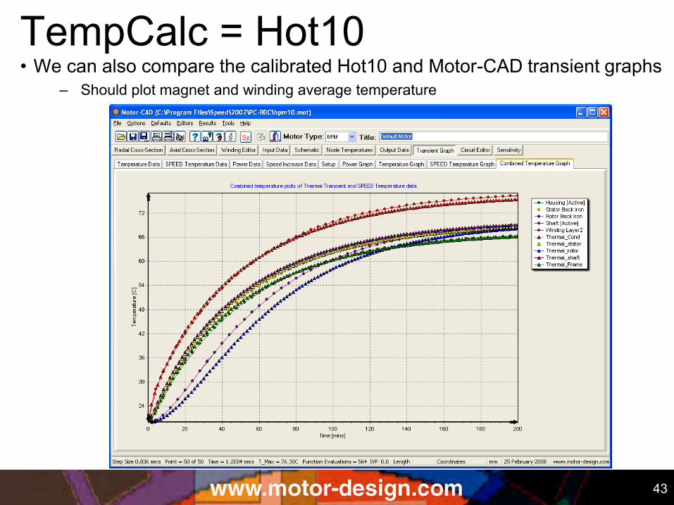
• We can also compare the calibrated Hot10 and Motor-CAD transient graphs – Should plot magnet and winding average temperature
TempCalc = Hot10
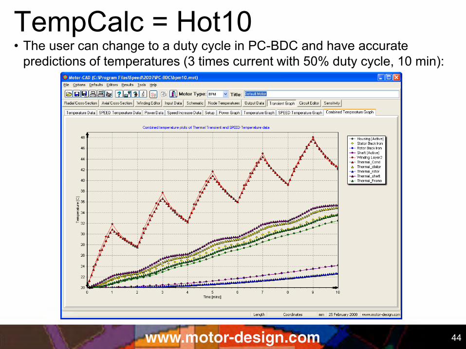
44
• The user can change to a duty cycle in PC-BDC and have accurate predictions of temperatures (3 times current with 50% duty cycle, 10 min):
TempCalc = Hot10
45 45
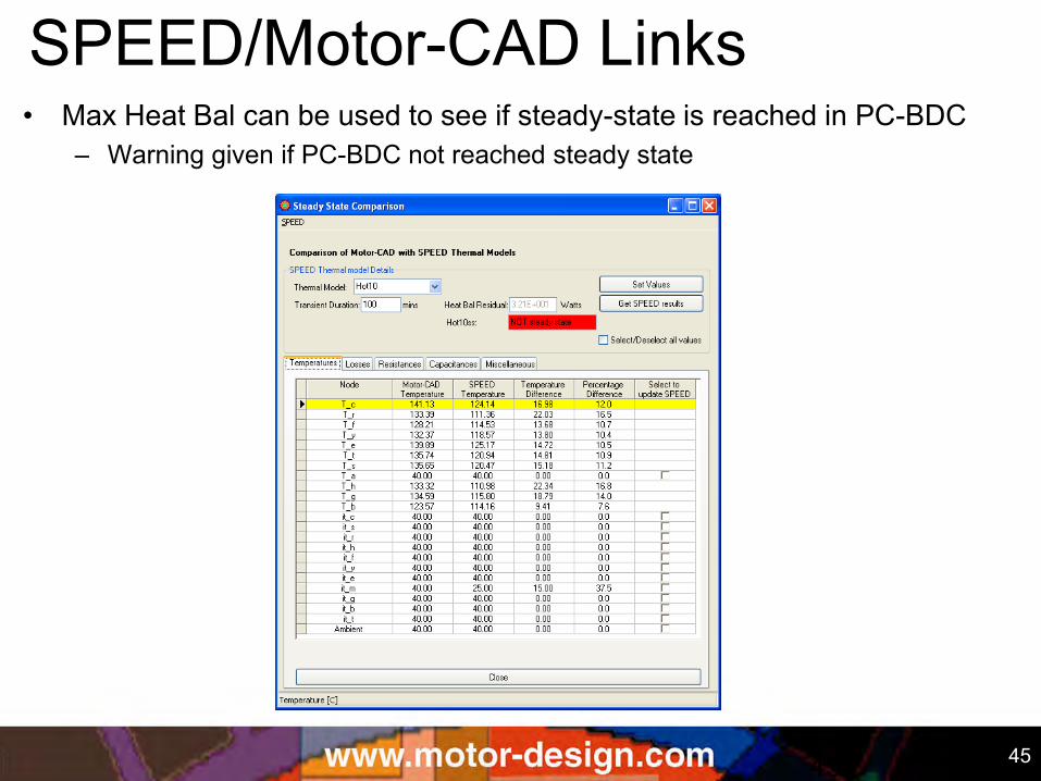
• Max Heat Bal can be used to see if steady-state is reached in PC-BDC – Warning given if PC-BDC not reached steady state
SPEED/Motor-CAD Links
46 46
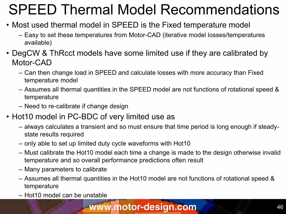
• Most used thermal model in SPEED is the Fixed temperature model – Easy to set these temperatures from Motor-CAD (iterative model losses/temperatures
available)
• DegCW & ThRcct models have some limited use if they are calibrated by Motor-CAD
– Can then change load in SPEED and calculate losses with more accuracy than Fixed temperature model
– Assumes all thermal quantities in the SPEED model are not functions of rotational speed & temperature
– Need to re-calibrate if change design
• Hot10 model in PC-BDC of very limited use as – always calculates a transient and so must ensure that time period is long enough if steady-
state results required – only able to set up limited duty cycle waveforms with Hot10 – Must calibrate the Hot10 model each time a change is made to the design otherwise invalid
temperature and so overall performance predictions often result – Many parameters to calibrate – Assumes all thermal quantities in the Hot10 model are not functions of rotational speed &
temperature – Hot10 model can be unstable
SPEED Thermal Model Recommendations
47 47
• Best to use Motor-CAD for thermal and SPEED for electromagnetics
• Motor-CAD has models to scale losses with speed, temperature and load so accurate thermal duty cycle analysis can be performed in Motor-CAD with the losses just input at one fixed speed and load and at set winding and magnet temperatures
–Only need to predict losses in SPEED at one load point and transfer these to Motor-CAD
SPEED Thermal Model Recommendations