Embed Size (px)
Citation preview

Installation instruction
Motor-driven blocking device EasyBlocker
108320
VdS - Class C G 196 089 G 197 051
108320Err_ENG.doc version 6.0a / 06.04.2016 page 1

Motor-driven blocking device EasyBlocker Installation instruction 108320
page
1 INTRODUCTION .......................................................................................................3
1.1 General information ......................................................................................................................3
1.2 Mechanic assembly / Safety.........................................................................................................3
1.3 Features of the blocking device ..................................................................................................3
2 INSTALLATION.........................................................................................................4
2.1 Assembly .......................................................................................................................................4 2.1.1 Blocking device ........................................................................................................................4 2.1.2 Counterpart ..............................................................................................................................5 2.1.3 Magnetic contact......................................................................................................................5 2.1.4 Emergency opening.................................................................................................................6
2.2 Electrical connection ....................................................................................................................7 2.2.1 General information .................................................................................................................8 2.2.2 Actuation with dynamic signals................................................................................................8 2.2.3 Actuating with a static signal....................................................................................................9 2.2.4 Switching on several blocking devices ................................................................................. 10
2.3 Magnetic contact and door monitoring ................................................................................... 12
2.4 Commissioning .......................................................................................................................... 12
3 MALFUNCTIONS ....................................................................................................13
3.1 Electrical emergency opening .................................................................................................. 14
3.2 Mechanic emergency opening.................................................................................................. 14
3.3 Replace the bolt ......................................................................................................................... 15
4 TECHNICAL DATA .................................................................................................16
5 DRILLING TEMPLATE............................................................................................17 Installation instruction Motor-driven blocking device EasyBlocker 108320 Item No: 108320.x Version: 6.0a / 06.04.2016 MA Document: 108320Err_ENG.doc © Copyright 2016: BSS Baumann Sicherheitssysteme GmbH
page 2 version 6.0a / 06.04.2016 108320Err_ENG.doc

Motor-driven blocking device EasyBlocker Installation instruction 108320
1 Introduction
1.1 General information
The blocking device serves to mechanically lock doors in order to avoid unintended entry of specially activated security areas in connection with a burglar alarm system or to refuse access to unauthorized persons for access control applications. This way, the motor-driven blocking device is part of a control unit in order to fulfill any unavoidability. It is possible to connect the blocking device to almost any system due to its flexible function. For access control applications it is possible to monitor the status of the door via an integrated magnetic contact. In this case, the blocking device only closes when the door had been closed.
The blocking device is available in 2 versions: Standard version (VdS - G 196 089) Battery version (VdS - G 197 051) in relation with wired security systems in relation with radio burglar alarm systems Item No Description Item No Description 108320.0 with magnetic contact, 3.5 m cable 108320.2 with magnetic contact, 3.5 m cable 108320.02 with magnetic contact, 10 m cable 108320.22 with magnetic contact, 10 m cable 108320.1 without magnetic contact, 3.5 m cable 108320.3 without magnetic contact, 3.5 m cable 108320.12 without magnetic contact, 10 m cable 108320.32 without magnetic contact, 10 m cable
1.2 Mechanic assembly / Safety
Due to the robust assembly made of plastic and stainless steel, a high reliability and durability of more than 500'000 cycles is being achieved. If the blocking device fails, there are electrical and mechanical emergency opening options available.
1.3 Features of the blocking device
• VdS - Class C • Low noise • Quiescent current demand for a standard version of type 1.2 mA • Quiescent current demand for a battery version of type 27 µA • Integrated magnetic contact VdS class B (G 197 541) • Feedback signal of the bolt position • Bolt exchangeable • To be connected to almost any system • Drive with static or dynamic signals • Several blocking devices can be connected in parallel or it is possible to implement a sequence control • Integrated intelligent control • Several closing trials, switching off when blocking • Stable plastic construction • Stainless steel cuff plate • Easy installation in the door frame. Only the counterpart will be installed to the door leaf.
108320Err_ENG.doc version 6.0a / 06.04.2016 page 3

Motor-driven blocking device EasyBlocker Installation instruction 108320
2 Installation The most advantageous installation place is as near as possible to the existing striking plate of the lock since in this position it will have minimum effects if the door gets distorted. The blocking device can be installed at any position. The following devices are required for the installation:
• Borer ø 16 mm or ø 20 mm for counterpart, borer ø 8 mm for magnet • Test equipment for the blocking device (Item No 108322.0) • Assembly aid (adhesive felt) to position the counterpart (is delivered together with the blocking device) • Ink pad to color the assembly aid (adhesive felt)
2.1 Assembly
Attention: When installing the blocking device on an emergency fire door, please check which structural measures are allowed so that the door will not lose its certification!
Attention: Installing the blocking device on escape doors is not allowed!
2.1.1 Blocking device
Mill a pocket of 20 mm width to build in the blocking device as well as a recess to install the cuff plate in the door frame. Provide enough space to fit a cable loop in the pocket for the blocking device so that sufficient cable reserves are available to extend the blocking device for service purposes. Exactly measure the position of the blocking device or use the included drilling template for emergency opening instructions and make marks on the door frame in order to be able to use mechanic emergency opening functions in case of an error. The exact installation dimensions are shown in figure 2-1 and figure 2-2. Please find further details about emergency opening in chapter 2.1.4 as well as in chapter 3. Optionally an angular cuff plate and a mounting housing is available to mount the blocking device.
8320AB201en.eps Illustration 2-1 - Assembly of the blocking device
Attention: Clean the milled out pocket before installing the blocking device. When screwing the fixing screws of the cuff plate please make sure that you do not damage the cable ducts with the fixing screws.
page 4 version 6.0a / 06.04.2016 108320Err_ENG.doc

Motor-driven blocking device EasyBlocker Installation instruction 108320
2.1.2 Counterpart
The counterpart is assembled in the door leaf. It needs to be assembled in a way that the bolt can extend to the limit stop without contact. The maximum distance between the cuff plate and the counterpart amounts to 8 mm. This way, it is guaranteed that the bolt will move far enough into the counterpart.
Assembly steps:
1. After having installed the blocking device, connect it to the test device (refer to the instructions of the test equipment for the connecting diagram). After supplying the distribution voltage (e.g. using an accumulator) the blocking device will open automatically.
2. Glue the assembly aid (adhesive felt) on the bolt of the blocking device and color it using an ink pad.
3. Close the door. 4. Lock the blocking device using the test device. The bolt will extend. After several locking trials the
bolt will move back since it cannot reach the end position. 5. Open the door. 6. On the door leaf you will recognize a color circle which shows the exact position of the counterpart. 7. Mark the center using a center punch and drill the hole according to the dimensions of the
counterpart. Please find the installation dimensions of the counterpart on the technical data sheet (also refer to chapter 4).
8. Assemble the counterpart. 9. Close the door and perform a functional check using the test device (also refer to chapter 2.4).
2.1.3 Magnetic contact
When using the magnetic contact install the magnet (8 mm x 30 mm) which is included in the delivery into the door leaf beside the counterpart. To do so, place a hole of ø 8 mm and a depth of 30 into the door leaf. You will find the correct position of the magnet in illustration 2-2 or determine the position by means of the attached drilling template for the magnetic contact.
Attention: On metal doors the magnetic force to switch the reed contacts is significantly reduced. Please check on site if it is necessary to use magnets of higher retention force.
It is possible to order a special magnet for metal doors under item No. 108320.M.
108320Err_ENG.doc version 6.0a / 06.04.2016 page 5

Motor-driven blocking device EasyBlocker Installation instruction 108320
2.1.4 Emergency opening
Electrical emergency opening: The connecting wires of the supply voltage need to be led to a position which is easily accessible in case of an error (e.g. behind the bell or the cover of the communicator, or others) in order to be able to use the electrical emergency opening options. Please find further information regarding the electrical emergency opening under chapter 3.1.
Mechanic emergency opening: Observe the following items during assembly in order to be able to use the mechanic emergency opening in case of an error:
• Mark the hole for the emergency opening on the door frame after having installed the blocking device in the door frame by means of the drilling template for emergency opening instructions or by means of the installation dimensions on illustration 2-2.
• If appropriate, drill the hole for emergency opening (ø 6 mm) into the door frame and close it using the attached cover caps.
Attention: Firstly disassemble the blocking device in order to avoid damages on the housing when drilling.
Please find further information regarding the mechanic emergency opening under chapter 3.2.
Illustration 2-2 - Installation dimensions of the blocking device 8320AB202en.eps
page 6 version 6.0a / 06.04.2016 108320Err_ENG.doc

Motor-driven blocking device EasyBlocker Installation instruction 108320
2.2 Electrical connection
Illustration 2-3 - Connection plan 8320AB203en.tif
Inputs and outputs of the blocking device
Signal Lead color Description
+12V Red Supply +12 V 0V Blue Supply 0 V Opened Green Input blocking device "Opened" Closed Brown Input blocking device "Closed" Mutual Yellow Mutual connection of the open and close input has to
be switched to +12 V or 0 V: Switched to +12 V ⇒ Inputs are activated 0 V Switched to 0 V ⇒ Inputs are activated +12 V
Opened output Black OC output: Display of the opened status Closed output White OC output: Display of the closed status
108320Err_ENG.doc version 6.0a / 06.04.2016 page 7

Motor-driven blocking device EasyBlocker Installation instruction 108320
2.2.1 General information
The device can be switched on in 6 different ways. In doing so, the actuation is enabled with a static signal or 2 dynamic signals. The polarity of the input signals is arbitrary due to an mutual connection. Furthermore, there are 2 outputs available which signalize the status of the blocking device. This way, the blocking device can be easily adapted to any system. There are measures provided for electrical emergency opening such as the option to interrupt the supply voltage. Please find further information regarding the electrical emergency opening in chapter 3.1.
2.2.2 Actuation with dynamic signals
These are timely limited impulses for the open and close actuations which are also used to actuate bistable door openers. For the impulse length the following values need to be observed:
Impulse length: > 50 ms for the standard versions > 200 ms for the battery versions
The impulse is saved in the blocking device and the closing or opening process is performed. Signal progress:
Illustration 2-4 8320AB204en.tif
Impulse term: ≥ 50 ms (Standard version) ≥ 200 ms (Battery version)
Examples for switching on: With outputs switching upon 0 V „Door opened“ and „Door closed“ (0V activated )
With outputs switching upon +12 V „Door opened“ and „Door closed“ (+12V activated )
Illustration 2-5 8320AB205en.tif
Illustration 2-6 8320AB206en.tif
page 8 version 6.0a / 06.04.2016 108320Err_ENG.doc

Motor-driven blocking device EasyBlocker Installation instruction 108320
2.2.3 Actuating with a static signal
This may be the activated and not activated exit of an BURGLAR ALARM CENTER or it may be a timely limited release signal for access control applications. A) Static signal at the open entry When activating the Open entry the blocking device opens, when deactivating the blocking device closes. The Closed entry always needs to be switched active. Signal progress and switch on example with "0V activated"-"inactivated" signal:
Illustration 2-7 8320AB207en.tif
Illustration 2-8 8320AB208en.tif
When controlling the Open entry via a PNP transistor upon +12V the mutual needs to be put on 0 V and the Closed entry on +12 V. B) Static signal at the closed entry When activating the Closed entry the blocking device closes, when deactivating the blocking device opens. The Opened entry always needs to be switched active. Signal progress and switch on example with „0V-activated“ - „activated“ signal:
Illustration 2-9 8320AB209en.tif
Illustration 2-10 8320AB210en.tif
When controlling the Closed entry via a PNP transistor upon +12V the mutual needs to be put on 0 V and the Opened entry on +12 V.
108320Err_ENG.doc version 6.0a / 06.04.2016 page 9

Motor-driven blocking device EasyBlocker Installation instruction 108320
2.2.4 Switching on several blocking devices
It is possible to switch blocking devices in parallel so that they all close at the same time. The control output(s) of the BURGLAR ALARM CENTER are only loaded at minimum due to the little input current of the blocking device (about 3 mA per input). In order to close the blocking devices one after another it is possible to cascade the blocking devices. The outputs „Closed output“ or „Opened output“ can be used for status display when switching on the LEDs. On the battery version the „Closed output“ and the „Opened output“ are implemented as impulse outputs. I.e. the outputs are controlled for 10 seconds after having opened or closed and then they switch off. If the input signal changes within this output control time, the correlate output will be deactivated immediately.
A) Parallel switching of several blocking devices
Illustration 2-11 8320AB211en.tif
page 10 version 6.0a / 06.04.2016 108320Err_ENG.doc

Motor-driven blocking device EasyBlocker Installation instruction 108320
B) Connect several blocking devices in series for standard version
Illustration 2-12 8320AB212en.tif
C) Connect several blocking devices in series for battery version
Illustration 2-13 8320AB213en.tif
108320Err_ENG.doc version 6.0a / 06.04.2016 page 11
Motor-driven blocking device EasyBlocker Installation instruction 108320
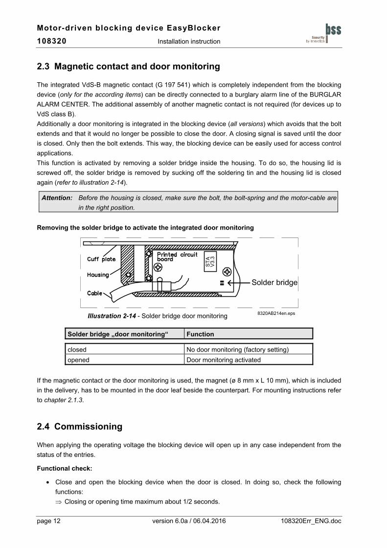
2.3 Magnetic contact and door monitoring
The integrated VdS-B magnetic contact (G 197 541) which is completely independent from the blocking device (only for the according items) can be directly connected to a burglary alarm line of the BURGLAR ALARM CENTER. The additional assembly of another magnetic contact is not required (for devices up to VdS class B). Additionally a door monitoring is integrated in the blocking device (all versions) which avoids that the bolt extends and that it would no longer be possible to close the door. A closing signal is saved until the door is closed. Only then the bolt extends. This way, the blocking device can be easily used for access control applications. This function is activated by removing a solder bridge inside the housing. To do so, the housing lid is screwed off, the solder bridge is removed by sucking off the soldering tin and the housing lid is closed again (refer to illustration 2-14).
Attention: Before the housing is closed, make sure the bolt, the bolt-spring and the motor-cable are in the right position.
Removing the solder bridge to activate the integrated door monitoring
Illustration 2-14 - Solder bridge door monitoring 8320AB214en.eps
Solder bridge „door monitoring“ Function
closed No door monitoring (factory setting) opened Door monitoring activated
If the magnetic contact or the door monitoring is used, the magnet (ø 8 mm x L 10 mm), which is included in the delivery, has to be mounted in the door leaf beside the counterpart. For mounting instructions refer to chapter 2.1.3.
2.4 Commissioning
When applying the operating voltage the blocking device will open up in any case independent from the status of the entries.
Functional check:
• Close and open the blocking device when the door is closed. In doing so, check the following functions: ⇒ Closing or opening time maximum about 1/2 seconds.
page 12 version 6.0a / 06.04.2016 108320Err_ENG.doc

Motor-driven blocking device EasyBlocker Installation instruction 108320
⇒ The bolt must neither contact nor interlock on the counterpart. The bolt extends without performing several locking trials.
⇒ The bolt can extend to full length since otherwise it would open up again after several locking trials.
• If the functionality is incorrect then check the wiring based on the signal descriptions and the examples for switching on described in chapter 2.2.
Attention: Every 22 seconds the system checks if the bolt is in position „Closed“ and, if necessary, updates the bolt position (standard version). For the battery version the bolt position will be checked and, if necessary, updated every 68 seconds.
Attention: Battery version - output „Closed output“ From version V2.0 (June 2013), the output will only be activated if the bolt is moved (i.e.
the bolt wasn’t in the right position when checked). Output active time is 10 seconds. If in state „Active“ the „Closed“ entry is operated again, the „Closed output“ is activated
again for 10 seconds. Until version V1.3 (to June 2013) the output active time was 0.5 seconds and was
activated on every bolt position check (every 68 seconds).
Attention: Battery version If the „Closed“ entry is actuated with a static signal, the „Closed output“ is activated every
10 seconds. because of higher current consumption at rest on state “Closed”, the battery version of
the blocking device should only be actuated with dynamic signals.
3 Malfunctions In case of malfunctions, please check the following options:
• Check wiring: Are all conductions correctly switched?
• Check control signals: Is the distribution voltage of +12V available on the blocking device? Are the necessary drive signals available on the blocking device?
• Check the installation: Does the bolt extend to full length? Does the bolt contact the counterpart?
• When the door monitoring is activated: Is the magnet at the correct position?
If the protected area remains obstructed, first use the electrical emergency opening options and if this is ineffective, use the mechanical emergency opening options as described in chapter 3.1 and chapter 3.2.
108320Err_ENG.doc version 6.0a / 06.04.2016 page 13

Motor-driven blocking device EasyBlocker Installation instruction 108320
3.1 Electrical emergency opening
Automatic opening of the blocking device after interrupting and switching on the distribution voltage again Independent from the fact if the control signal is fed, the blocking device will always open up after feeding the distribution voltage. During this process, rattle at the door so that the blocking device opens if mechanical problems on the door are causing that it does not open. When installing the blocking device, the distribution voltage needs to be mounted at an accessible point (e.g. behind the bell or the cover of the communicator, or others) so that it can be interrupted there in case of a failure. This emergency opening type will only be successful if the electronic, which is integrated in the blocking device, is working properly.
3.2 Mechanic emergency opening
If the electrical emergency opening option is not successful, you can apply two different mechanic emergency opening options.
A) Retract bolts by shifting the motor back of its fixture When shifting the motor back of its fixture, the bolt will retract due to an integrated spring mechanism. The motor can be shifted out of its fixture from both sides of the door.
To do so, please proceed as follows:
1. Drill a hole of ø 6 mm at the positions which had been marked on the door frame when mounting or just remove the cover cap on the door frame (if the emergency opening hole had already been applied during assembly).
Attention: Do not drill too deep, make sure that the housing of the blocking device is not damaged!
2. Shift the motor back of its fixture by pressing a slot screw driver (max. ø 4 mm) into the emergency opening hole of the blocking device until the motor mechanically decouples and the bolt moves in. During this process, slightly rattle at the door in order that the blocking device can open if there is any additional mechanic problem on the door.
Attention: If the operating voltage is applied the "Closed position" of the bolt is monitored and returned to the end position within 22 seconds (68 seconds)!
B) Predetermine breaking point at the bolt The bolt (ø 8 mm) of the blocking device processes a predetermine breaking point which responds at a force of more than 1 kN (at a maximum distance of 5 mm from the cuff plate).
Spare-Bolts are available under the item No. 108320.B
page 14 version 6.0a / 06.04.2016 108320Err_ENG.doc

Motor-driven blocking device EasyBlocker Installation instruction 108320
3.3 Replace the bolt
If necessary, the bolt can be replaced. To do so, please proceed as follow:
1. Disconnect the power supply from blocking device.
2. Dismount the blocking device from the door frame (loose the two screws from cuff plate).
3. Detach the housing lid - for this purpose keep the housing horizontally, with lid on top. Instead loose the six thermoplastic screws 2.5 x 10, PZ1.
4. Remove the old / defective bolt.
5. Make sure, the bolt spring is in the correct position. If necessary, the spring from the bolt accessories can be used.
6. Put the new bolt from behind in the corresponding duct in the housing. For this purpose lift the motor on gearwheel side a little.
Attention: The bolt can be put deeper in the housing, so it sticks out from cuff plate. When the power supply is switched on, the bolt will automatically be moved in the position „Open“.
7. Please check that all parts are in correct position (bolt-spring, bolt, motor and motor-cable). Close the housing lid again and tighten it by using the screws.
Attention: Before the housing is closed, make sure the motor-cable lies correctly in the proper duct and cannot be damaged by the housing lid !
8. Switch on the blocking device power supply. The bolt will automatically be moved in the position „Open“.
9. Mount the blocking device into the door frame and attach the cuff plate. Test the function of the blocking device.
Troubleshooting
The product is designed state-of-the-art. It needs to be thoroughly checked if the products is free from material and functioning defects when it is leaving the factory. Nonetheless, if any defects are occurring which cannot be repaired on site, please send us the defective device including a detailed error description.
108320Err_ENG.doc version 6.0a / 06.04.2016 page 15

Motor-driven blocking device EasyBlocker Installation instruction 108320
4 Technical data Operating nominal voltage 12 V DC
Operating voltage range 7 V DC to 15 V DC
Current consumption at rest (entries inactive) about 1.2 mA (standard version) about 40 µA (battery version)
Current consumption during locking process about 35 mA / 12 V DC (50 mA / 8 V DC; 30 mA / 15 V DC)
Current consumption when locking max. 150 mA / 12 V DC (230 mA / 8 V DC; 120 mA / 15 V DC) (only short term, since automatic switching off)
Please note: at the beginning of each motor actuation, the current consumption is like “locking” state and decreases within 10…30 msec to “current consumption during locking process” !
Required current to activate the inputs < 3 mA (control optionally towards plus or minus)
Minimum pulse duration at the inputs > 50 ms (standard version) > 200 ms (battery version)
Loading capacity of the feedback outputs 50 mA (OC-outputs switching approach minus)
Function of the feedback outputs static (standard version) dynamic, about 10 seconds (battery version)
Bolt Diameter 8 mm, bolt path 11.5 mm
Maximum distance cuff plate to counterpart 8 mm
Closing / Opening time < 0.5 s (independent of operating voltage)
Locking force > 5 N (independent of operating voltage)
Admissible shearing force 1.0 kN at a maximum distance of 5 mm from the cuff plate 0.75 kN at a distance of 8 mm from the cuff plate
Operating temperature range Storage temperature range
-25 °C ... +60 °C -40 °C ... +70 °C
Climates according to VdS (IEC 60 068-2) class III
Degree of protection IP 43
Protection against electromagnetic influences (EMV) 2014/30/EU and according to VdS 2110
Housing: dimensions, material W 19 x H 135 x D 28 mm, plastic (PA GF)
cuff plate: dimensions, material W 20 x H 175 x D 2 mm, Stainless steel 1.4301
Weight without connecting cables ca. 0.2 kg
Cable LiYY 7 x 0.14 mm²
Inner diameter Outer diameter Length Collar diameter
Counterpart 1 Counterpart 2 12 mm 16 mm 16 mm 20 mm 19 mm 22 mm 21 mm 28 mm
Diameter Head diameter Length
Cover caps black / white / brown 6.0 mm 13.0 mm 6.0 mm
Diameter Length
Magnet for door monitoring 8 mm 10 mm
VdS approval No - Blocking dev. - Standard version G 196 089
VdS approval No - Blocking dev. - Battery version G 197 051
VdS approval No - Magnetic contact G 197 541
page 16 version 6.0a / 06.04.2016 108320Err_ENG.doc

Motor-driven blocking device EasyBlocker Installation instruction 108320
108320Err_ENG.doc version 6.0a / 06.04.2016 page 17
5 Drilling template Attention: Drilling templates on a scale of 1:1 Please copy this page and cut out the drilling templates!
8320AB51en.eps 8320AB52en.eps
Illustration 5-1 - Drilling template emergency opening Illustration 5-2 Hole (ø6 mm) depending on the position of the cable entry point Drilling template (A) or (B) to be performed at point A' or B' Magnet position at the door leaf