Embed Size (px)
DESCRIPTION
induction motor fundamentals
Citation preview
Comprehensive Guide to Understanding Motor Fundamentals
Instruction Manual
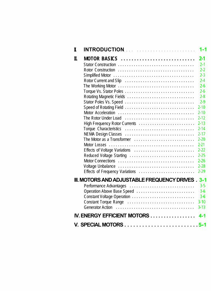
II. INTRODUCTION. . . . . . . . . . . . . . . . . . . . . . . . . . . . 1 - 1
II. MOTOR BASICS . . . . . . . . . . . . . . . . . . . . . . . . . . . . 2 - 1Stator Construction . . . . . . . . . . . . . . . . . . . . . . . . . . . . . . . . . . 2-1Rotor Construction . . . . . . . . . . . . . . . . . . . . . . . . . . . . . . . . . . 2-2Simplified Motor . . . . . . . . . . . . . . . . . . . . . . . . . . . . . . . . . . . . 2-3Rotor Current and Slip . . . . . . . . . . . . . . . . . . . . . . . . . . . . . . . 2-4The Working Motor . . . . . . . . . . . . . . . . . . . . . . . . . . . . . . . . . . 2-6Torque Vs. Stator Poles . . . . . . . . . . . . . . . . . . . . . . . . . . . . . . . 2-6Rotating Magnetic Fields . . . . . . . . . . . . . . . . . . . . . . . . . . . . . . 2-8Stator Poles Vs. Speed . . . . . . . . . . . . . . . . . . . . . . . . . . . . . . . 2-9Speed of Rotating Field . . . . . . . . . . . . . . . . . . . . . . . . . . . . . . . 2-10Motor Acceleration . . . . . . . . . . . . . . . . . . . . . . . . . . . . . . . . . . 2-10The Rotor Under Load . . . . . . . . . . . . . . . . . . . . . . . . . . . . . . . 2-12High Frequency Rotor Currents . . . . . . . . . . . . . . . . . . . . . . . . . 2-13Torque Characteristics . . . . . . . . . . . . . . . . . . . . . . . . . . . . . . . 2-14NEMA Design Classes . . . . . . . . . . . . . . . . . . . . . . . . . . . . . . . 2-17The Motor as a Transformer . . . . . . . . . . . . . . . . . . . . . . . . . . . 2-20Motor Losses . . . . . . . . . . . . . . . . . . . . . . . . . . . . . . . . . . . . . . 2-21Effects of Voltage Variations . . . . . . . . . . . . . . . . . . . . . . . . . . . 2-22Reduced Voltage Starting . . . . . . . . . . . . . . . . . . . . . . . . . . . . . 2-25Motor Connections . . . . . . . . . . . . . . . . . . . . . . . . . . . . . . . . . . 2-26Voltage Unbalance . . . . . . . . . . . . . . . . . . . . . . . . . . . . . . . . . . 2-28Effects of Frequency Variations . . . . . . . . . . . . . . . . . . . . . . . . . 2-29
Ill. MOTORS AND ADJUSTABLE FREQUENCY DRIVES . 3 - 1Performance Advantages . . . . . . . . . . . . . . . . . . . . . . . . . . . . . 3-5Operation Above Base Speed . . . . . . . . . . . . . . . . . . . . . . . . . . 3-6Constant Voltage Operation . . . . . . . . . . . . . . . . . . . . . . . . . . . . 3-6Constant Torque Range . . . . . . . . . . . . . . . . . . . . . . . . . . . . . . 3-10Generator Action . . . . . . . . . . . . . . . . . . . . . . . . . . . . . . . . . . . 3-13
IV. ENERGY EFFICIENT MOTORS . . . . . . . . . . . . . . . . . 4-1
V. SPECIAL MOTORS . . . . . . . . . . . . . . . . . . . . . . . . . . 5 - 1
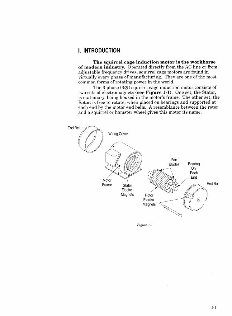
II. MOTOR BASICS
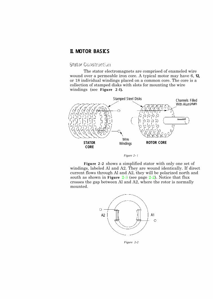
The stator electromagnets are comprised of enameled wirewound over a permeable iron core. A typical motor may have 6, 12,or 18 individual windings placed on a common core. The core is acollection of stamped disks with slots for mounting the wirewindings (see Figure 2-l).
Stamped Steel Disks
STATORCORE
Windings
Channels Filled
ROTOR CORE
num
Figure 2 - 1
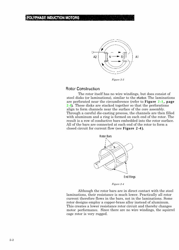
Figure 2-2 shows a simplified stator with only one set ofwindings, labeled Al and A2. They are wound identically. If directcurrent flows through Al and A2, they will be polarized north andsouth as shown in Figure 2-3 (see page 2-2). Notice that fluxcrosses the gap between Al and A2, where the rotor is normallymounted.
Figure 2-2
2-1
Al
Figure 2-3
The rotor itself has no wire windings, but does consist ofsteel disks (or laminations), similar to the stator. The laminationsare perforated near the circumference (refer to Figure 2-1, page2-l). These disks are stacked together so that the perforationsalign to form channels near the surface of the core assembly.Through a careful die-casting process, the channels are then filledwith aluminum and a ring is formed on each end of the rotor. Theresult is a row of conductive bars embedded into the rotor surface.All of the bars are connected at each end of the rotor to form aclosed circuit for current flow (see Figure 2-4).
Rotor Bars
End Rings
Figure 2-4
Although the rotor bars are in direct contact with the steellaminations, their resistance is much lower. Practically all rotorcurrent therefore flows in the bars, not in the laminations. Somerotor designs employ a copper-brass alloy instead of aluminum.This creates a lower resistance rotor circuit and thereby changesmotor performance. Since there are no wire windings, the squirrel-cage rotor is very rugged.
2-2
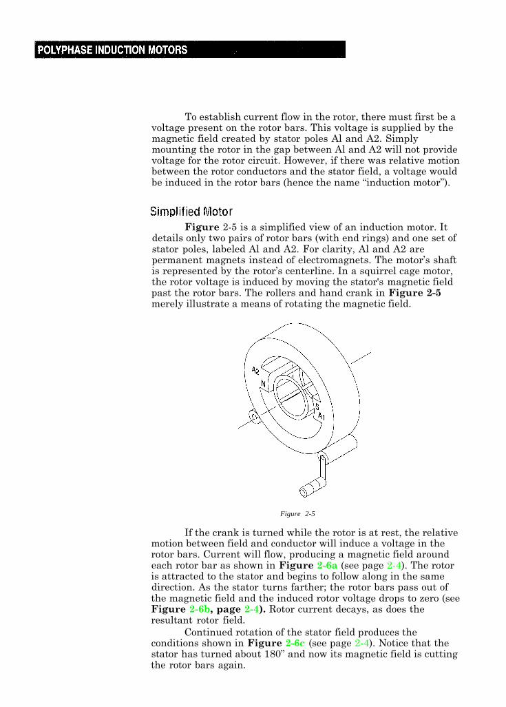
To establish current flow in the rotor, there must first be avoltage present on the rotor bars. This voltage is supplied by themagnetic field created by stator poles Al and A2. Simplymounting the rotor in the gap between Al and A2 will not providevoltage for the rotor circuit. However, if there was relative motionbetween the rotor conductors and the stator field, a voltage wouldbe induced in the rotor bars (hence the name “induction motor”).
ie rFigure 2-5 is a simplified view of an induction motor. It
details only two pairs of rotor bars (with end rings) and one set ofstator poles, labeled Al and A2. For clarity, Al and A2 arepermanent magnets instead of electromagnets. The motor’s shaftis represented by the rotor’s centerline. In a squirrel cage motor,the rotor voltage is induced by moving the stator's magnetic fieldpast the rotor bars. The rollers and hand crank in Figure 2-5merely illustrate a means of rotating the magnetic field.
Figure 2-5
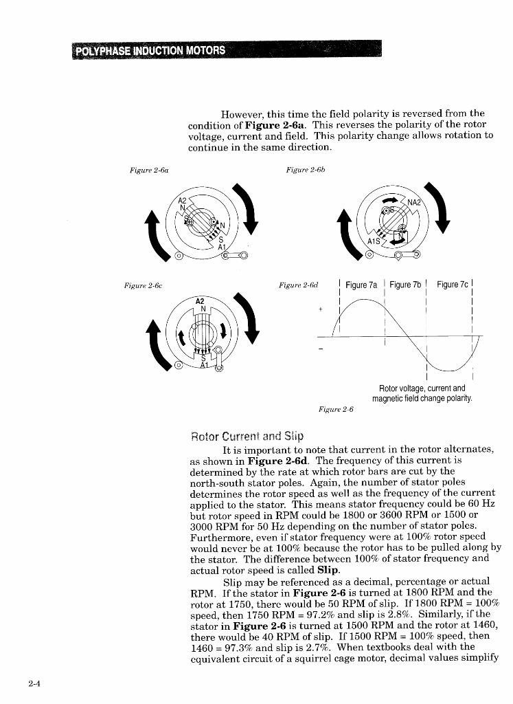
If the crank is turned while the rotor is at rest, the relativemotion between field and conductor will induce a voltage in therotor bars. Current will flow, producing a magnetic field aroundeach rotor bar as shown in Figure 2-6a (see page 2-4). The rotoris attracted to the stator and begins to follow along in the samedirection. As the stator turns farther; the rotor bars pass out ofthe magnetic field and the induced rotor voltage drops to zero (seeFigure 2-6b, page 2-4). Rotor current decays, as does theresultant rotor field.
Continued rotation of the stator field produces theconditions shown in Figure 2-6c (see page 2-4). Notice that thestator has turned about 180” and now its magnetic field is cuttingthe rotor bars again.
2-3
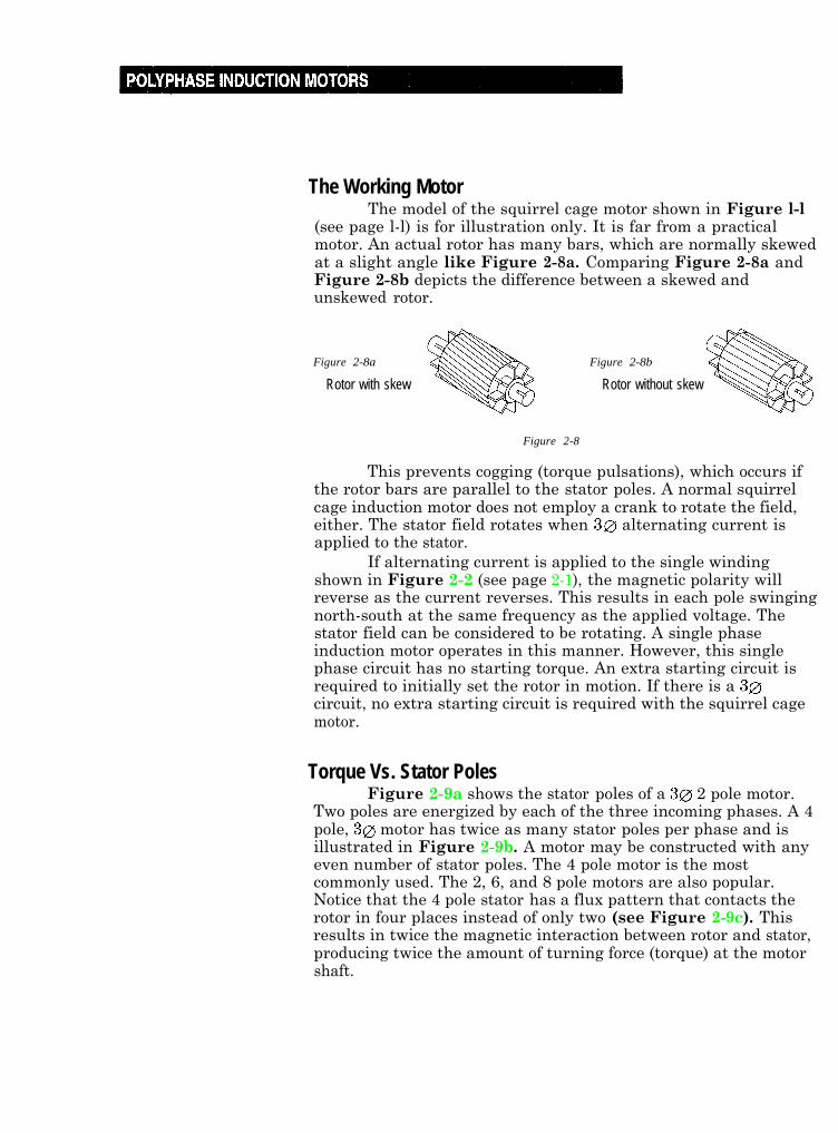
The Working MotorThe model of the squirrel cage motor shown in Figure l-l
(see page l-l) is for illustration only. It is far from a practicalmotor. An actual rotor has many bars, which are normally skewedat a slight angle like Figure 2-8a. Comparing Figure 2-8a andFigure 2-8b depicts the difference between a skewed andunskewed rotor.
Figure 2-8a
Rotor with skew
Figure 2-8b
Rotor without skew
Figure 2-8
This prevents cogging (torque pulsations), which occurs ifthe rotor bars are parallel to the stator poles. A normal squirrelcage induction motor does not employ a crank to rotate the field,either. The stator field rotates when 3~ alternating current isapplied to the stator.
If alternating current is applied to the single windingshown in Figure 2-2 (see page 2-1), the magnetic polarity willreverse as the current reverses. This results in each pole swingingnorth-south at the same frequency as the applied voltage. Thestator field can be considered to be rotating. A single phaseinduction motor operates in this manner. However, this singlephase circuit has no starting torque. An extra starting circuit isrequired to initially set the rotor in motion. If there is a 30circuit, no extra starting circuit is required with the squirrel cagemotor.
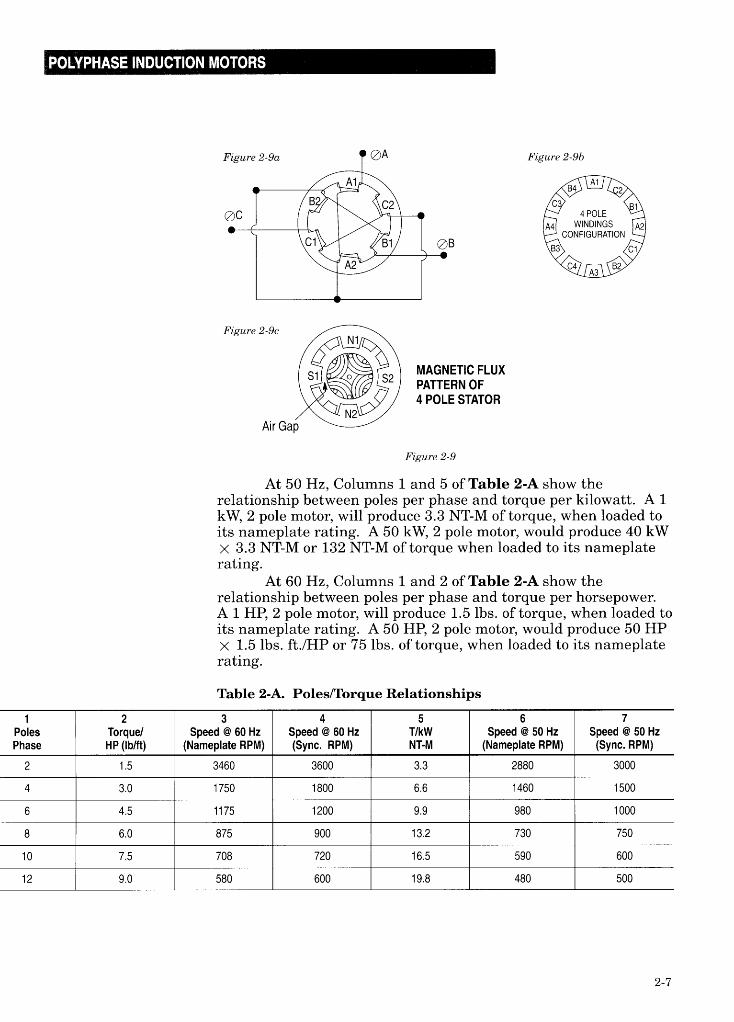
Torque Vs. Stator PolesFigure 2-9a shows the stator poles of a 30 2 pole motor.
Two poles are energized by each of the three incoming phases. A 4pole, 30 motor has twice as many stator poles per phase and isillustrated in Figure 2-9b. A motor may be constructed with anyeven number of stator poles. The 4 pole motor is the mostcommonly used. The 2, 6, and 8 pole motors are also popular.Notice that the 4 pole stator has a flux pattern that contacts therotor in four places instead of only two (see Figure 2-9c). Thisresults in twice the magnetic interaction between rotor and stator,producing twice the amount of turning force (torque) at the motorshaft.
2-6
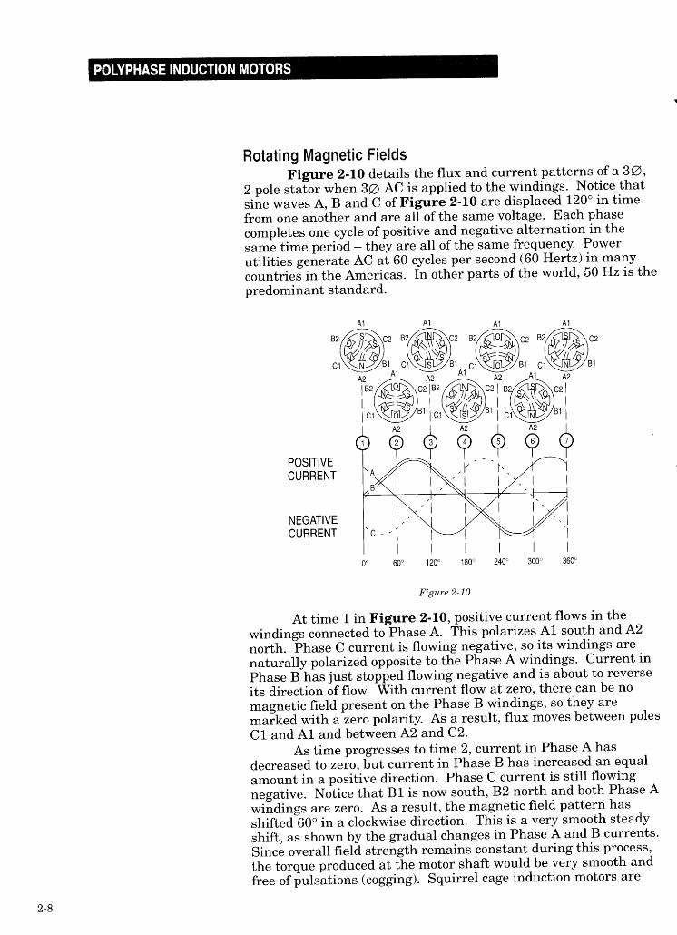
often operated from square waves generated by adjustablefrequency drives instead of sine waves of current. At lowfrequencies (below 20 Hertz), a square wave’s magnetic field doesnot shift smoothly from one position to the next, and cogging maybe noticeable.
Follow diagrams of Figure 2-10 through times 3, 4, 5, 6and 7 to verify that the magnetic field does, in fact, rotate. Thefield at time 7 is identical to the field at time 1 in the cycle. Themagnetic field of a 2 pole motor makes one complete rotationduring one electrical cycle. If a rotor is placed inside the stator, itwill make almost one rotation in one electrical cycle (depending onthe amount of slip between rotor and stator). The direction ofmotor rotation may be reversed by switching any two of the statorleads. This causes the stator field to reverse direction.
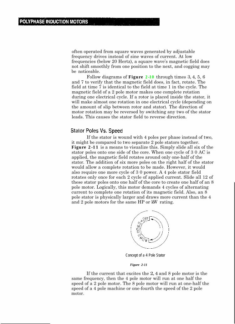
If the stator is wound with 4 poles per phase instead of two,it might be compared to two separate 2 pole stators together.Figure 2-11 is a means to visualize this. Simply slide all six of thestator poles onto one side of the core. When one cycle of 3 0 AC isapplied, the magnetic field rotates around only one-half of thestator. The addition of six more poles on the right half of the statorwould allow a complete rotation to be made. However, it wouldalso require one more cycle of 3 0 power. A 4 pole stator fieldrotates only once for each 2 cycle of applied current. Slide all 12 ofthese stator poles onto one half of the core to create one half of an 8pole motor. Logically, this motor demands 4 cycles of alternatingcurrent to complete one rotation of its magnetic field. Also, an 8pole stator is physically larger and draws more current than the 4and 2 pole motors for the same HP or kW rating.
Concept of a 4 Pole Stator
Figure 2-11
If the current that excites the 2, 4 and 8 pole motor is thesame frequency, then the 4 pole motor will run at one half thespeed of a 2 pole motor. The 8 pole motor will run at one-half thespeed of a 4 pole machine or one-fourth the speed of the 2 polemotor.
2-9
Speed of Rotating FieldSince the stator field speed is exactly dependent on the
frequency of the applied current, it is said to be in synchronismwith the applied current.
The speed at which the stator field rotates is thereforecalled Synchronous Speed. The speed of the rotor is calledRunning Speed. It differs only by the amount of slip as shown inthe equation below:
Where:Ns = Synchronous speed of motor in RPMF = applied frequency in hertzP = number of poles per phase120 = conversion factor
(Equation 2-1)
Synchronous speed may be altered by changing either thefrequency applied or the number of poles. Multi-speed motorshave external connections that allow an operator to switch thestator from 2 poles to 4 poles or 4 poles to 6 poles, etc. Thisprovides only a limited number of definite speeds, such as thoseshown in Table 2-A (page 2-7). This table lists the synchronousspeeds of various motors excited by the same frequency. If speedsother than those listed are desired, it is necessary to change themotor’s applied frequency.
This is commonly done by powering the motor from anadjustable frequency drive. Using a drive to generate the appliedfrequency produces an infinitely variable speed range from 0 RPMto as high as 100,000 RPM (if required).
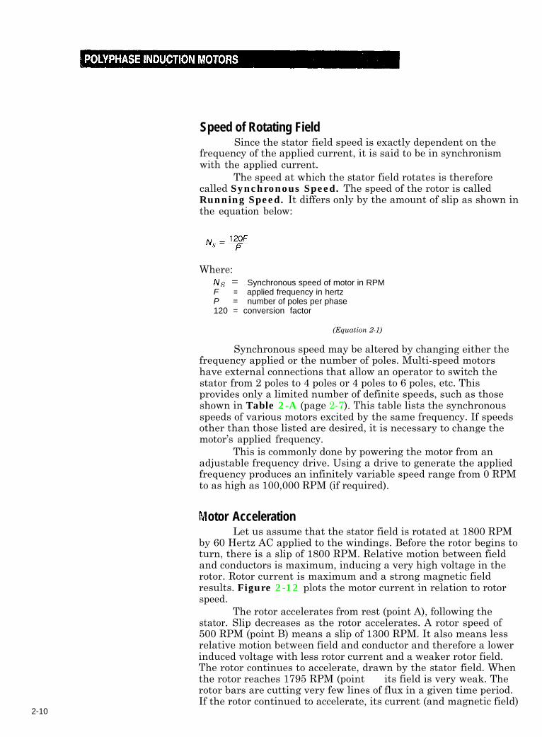
otor AccelerationLet us assume that the stator field is rotated at 1800 RPM
by 60 Hertz AC applied to the windings. Before the rotor begins toturn, there is a slip of 1800 RPM. Relative motion between fieldand conductors is maximum, inducing a very high voltage in therotor. Rotor current is maximum and a strong magnetic fieldresults. Figure 2-12 plots the motor current in relation to rotorspeed.
The rotor accelerates from rest (point A), following thestator. Slip decreases as the rotor accelerates. A rotor speed of500 RPM (point B) means a slip of 1300 RPM. It also means lessrelative motion between field and conductor and therefore a lowerinduced voltage with less rotor current and a weaker rotor field.The rotor continues to accelerate, drawn by the stator field. Whenthe rotor reaches 1795 RPM (point E), its field is very weak. Therotor bars are cutting very few lines of flux in a given time period.If the rotor continued to accelerate, its current (and magnetic field)
2-10
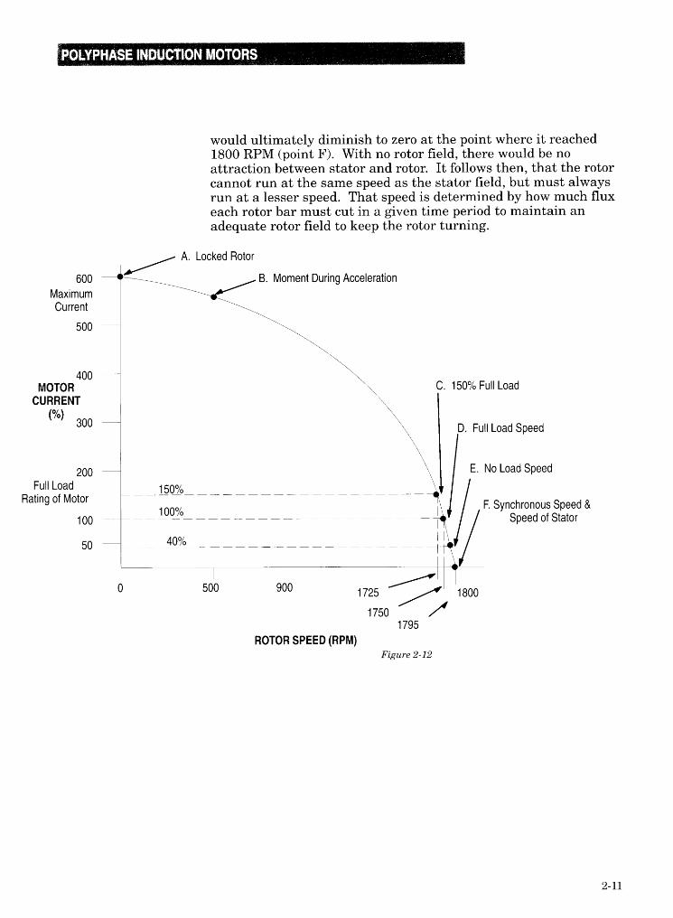
otor Under LoadIf no work is required at the motor shaft (no load applied),
the rotor will turn at approximately 1795 RPM (point E). Slip isminimal and the resulting rotor field is very weak. Yet, rotor-stator attraction is just strong enough to produce enough torque tokeep the rotor turning at 1795 RPM. If a load is now applied tothe motor shaft, it immediately slows down, since the torque beingproduced was just enough to keep the rotor at 1795 RPM. If thestator speed remains constant (1800 RPM), then as the rotor slowsdown, its bars automatically begin to cut more lines of stator fluxper unit of time. The rotor field strengthens and more torque isproduced. The rotor will continue to slow down (or slip back) untiladequate torque is produced to power the load and maintainrotation. This might correspond to point D in Figure 2-12 (seepage 2-11). where slip has increased to 50 RPM, and current hasincreased to 100%. If the load is removed, the torque beingproduced will cause the rotor to accelerate back to its no load speedof 1795 RPM (point E).
If the load is increased, again the motor will slow down toproduce greater torque by the rotor bars cutting more lines of flux.Speed stabilizes when the motor torque matches the load torque,this time perhaps at point C. The motor will maintain this speedas long as the load is constant. Further load increases causegreater current flow; beyond the safe limits of motor operation. Anoverpowering load may cause the motor to stall completely, causingextremely high currents to flow (point A). Overcurrent protectionmust be installed to protect the motor in such an event. Undernormal circumstances this magnitude of current occurs onlyduring starting, (which lasts less than one second) while the rotorattains its running speed.
When the rotor is stationary, either when stalled by a loador during starting, rotor frequency is equal to stator frequency. Ifthe stator is excited by 60 Hz, then rotor frequency is also 60 Hz orif the stator is excited by 50 Hz the rotor frequency is also 50 Hz.This is true regardless of the number of stator poles a motor has.A 2 pole stator turns at 3600 RPM (@ 60 Hz) or 3000 RPM (@ 50Hz) and induces 1 cycle of rotor voltage as each pole pair passes arotor bar. A 4 pole sator turns at half the speed but has twice thepole pairs cutting each rotor bar. It induces 2 cycles of rotorvoltage per revolution, matching the rotor frequency of a 2 polemachine.
2-12
When the rotor field shifts (during high slip) it not onlyaffects motor current, but torque as well. Recall that torqueresults from the magnetic attraction between rotor and stator.
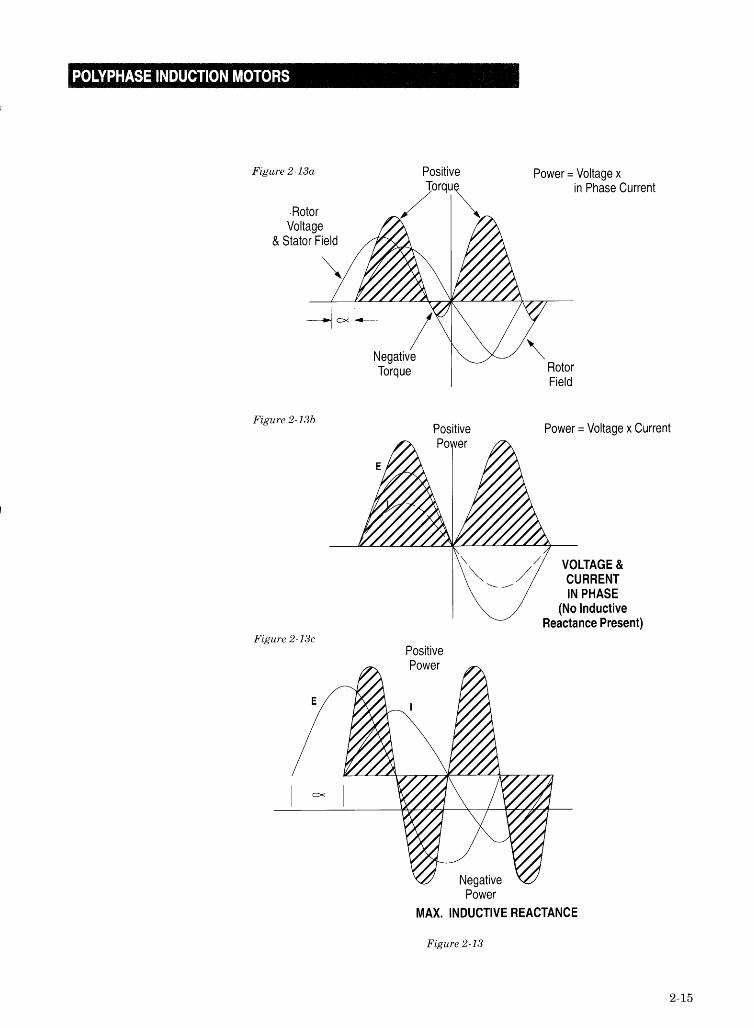
Increased inductive reactance causes the rotor current (andresultant field) to lag rotor voltage. Since the rotor voltage isin-phase with the stator field, the rotor field must be out of phasewith the stator field. Figure 2-13a shows the rotor field laggingthe stator field and rotor voltage by the angle m (the cosine of x isa measure of power factor). Notice that positive motor torque isproduced only during the periods when stator and rotor fields arein-phase. Compare this with Figure 2-13b, where voltage andcurrent are both in-phase. The out-of-phase rotor field (inFigure 2-13a) actually produces negative torque, or a retardingforce. As power factor decreases further, torque suffers more.Figure 2-13c shows a condition of maximum current lag ( m - 90°>resulting in negative torque completely cancelling positive torque.Although maximum voltage and current flow in such a circuit, nopower is produced.
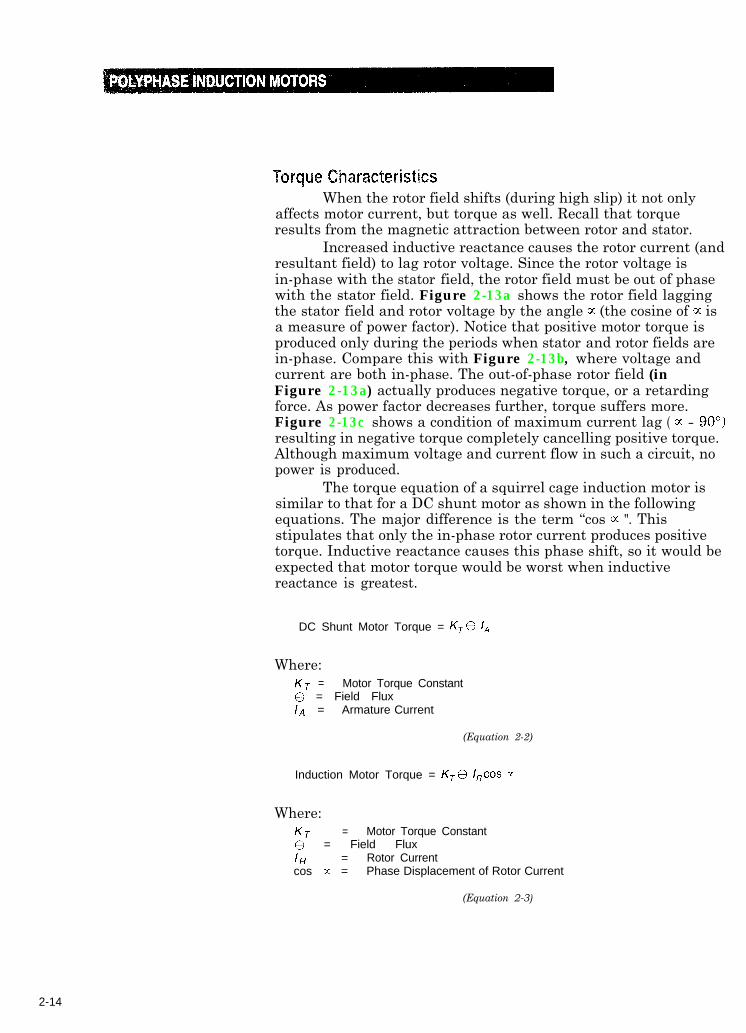
The torque equation of a squirrel cage induction motor issimilar to that for a DC shunt motor as shown in the followingequations. The major difference is the term “cos m ". Thisstipulates that only the in-phase rotor current produces positivetorque. Inductive reactance causes this phase shift, so it would beexpected that motor torque would be worst when inductivereactance is greatest.
DC Shunt Motor Torque = K,0 1,
Where:KT = Motor Torque Constant0 = Field FluxIA = Armature Current
(Equation 2-2)
Induction Motor Torque = K,G I,cos m
Where:KT = Motor Torque Constant8 = Field FluxI/q = Rotor Currentcos c-c = Phase Displacement of Rotor Current
(Equation 2-3) 2-3)
2-14
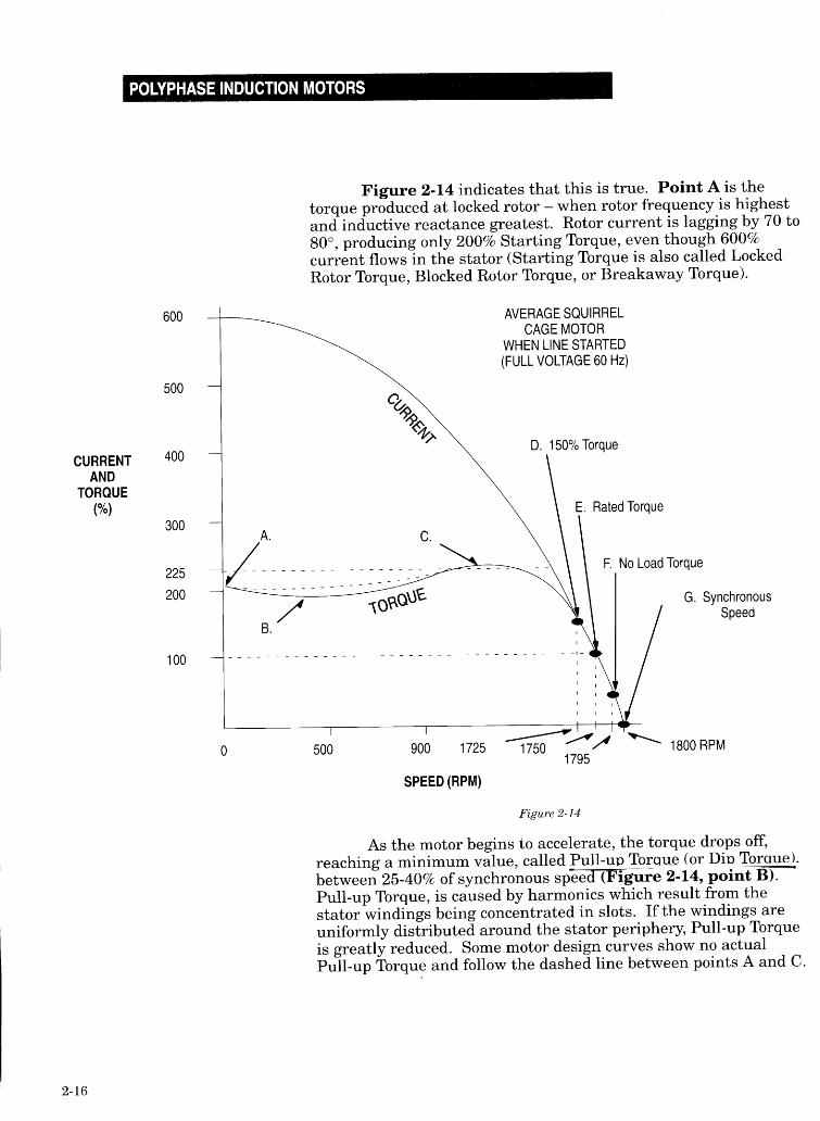
As acceleration continues, rotor frequency and inductivereactance decreases. The rotor flux moves more in-phase withstator flux and torque increases. Maximum Torque (orBreak-down Torque) is developed at point C in Figure 2-14, whereinductive reactance becomes equal to the rotor resistance. Beyondpoint C, (points D, E and F) the inductive reactance continues todrop off, but rotor current also decreases at the same rate,reducing torque.
statorPoint G is synchromous speed and proves that if rotor andare at the same speed, rotor current and torque are zero.At running speed, the motor will operate between points F
and D, depending on load. However, temporary load surges maycause it to slip all the way back near point C on the “knee” of thecurve.
Beyond point C, the power factor decreases faster thancurrent increases, causing torque to drop-off. On the linear part ofthe motor curve (points C to G), rotor frequency is only 1 to 3 Hertz- almost DC. Inductive reactance is essentially zero and rotorpower factor approaches unity. Torque and current now becomedirectly proportional - 100% current produces 100% torque. If amotor has a nameplate current of 3.6 amps, then when it draws 3.6amps (at proper voltage and frequency) it must be producing 100%of its nameplate torque. Torque and current remain directlyproportional up to approximately 10% slip. This relationship isvery useful when troubleshooting the motor and driven machine.
Notice that as motor load increases from zero (point F) to100%, (point E) the speed drops only 45-55 RPM, about 3% ofsynchronous speed. This makes the squirrel cage induction motorvery suitable for most constant speed applications (such asconveyors) where, in some cases, 3% speed regulation might beacceptable. This compares favorably with shunt wound DCmotors. If better speed regulation is required, the squirrel cagemotor may be operated from a closed loop regulator. As analternative, a reluctance synchronous induction motor (see pages2-12 and 2-13) may be used instead of a squirrel cage inductionmotor.
NEMA Design ClassesIn the U.S., the National Electrical Manufacturers’
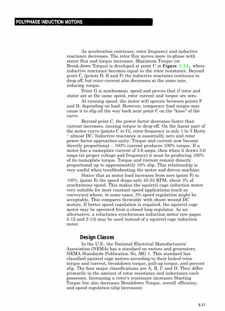
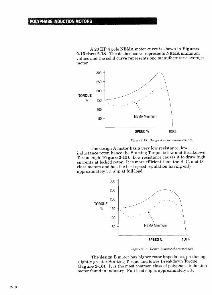
Association (NEMA) has a standard on motors and generators;NEMA Standards Publication No. MG 1. This standard hasclassified squirrel cage motors according to their locked rotortorque and current, breakdown torque, pull-up torque, and percentslip. The four major classifications are A, B, C and D. They differprimarily in the amount of rotor resistance and inductance eachpossesses. Increasing a rotor’s resistance increases StartingTorque but also decreases Breakdown Torque, overall efficiency,and speed regulation (slip increases).
2-17
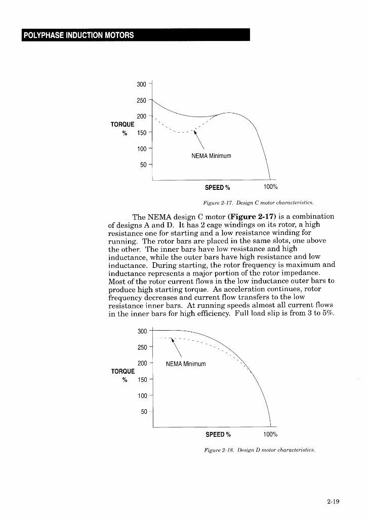
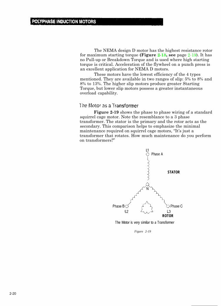
The NEMA design D motor has the highest resistance rotorfor maximum starting torque (Figure 2-18, see page 2-19). It hasno Pull-up or Breakdown Torque and is used where high startingtorque is critical. Acceleration of the flywheel on a punch press isan excellent application for NEMA D motors.
These motors have the lowest efficiency of the 4 typesmentioned. They are available in two ranges of slip: 5% to 8% and8% to 13%. The higher slip motors produce greater StartingTorque, but lower slip motors possess a greater instantaneousoverload capability.
Figure 2-19 shows the phase to phase wiring of a standardsquirrel cage motor. Note the resemblance to a 3 phasetransformer. The stator is the primary and the rotor acts as thesecondary. This comparison helps to emphasize the minimalmaintenance required on squirrel cage motors, “It’s just atransformer that rotates. How much maintenance do you performon transformers?”
L1
PPhase A
$ STATOR
ROTOR
The Motor is very similar to a Transformer
Figure 2-19
2-20
A transformer’s magnetic coupling is fixed, but the motor’scoupling between stator and rotor changes. When slip is 1, thecoupling is optimum. This occurs at locked rotor, when theinduced rotor voltage is highest and rotor current is maximum,Figure 2-12, point A (page 2-11). This may be compared to thetransformer with a shorted secondary circuit. As the rotoraccelerates, slip decreases from 1 to as little as 0.1 (no load speed).The primary to secondary coupling deteriorates and induced rotorvoltage is very low. Rotor current is as low as the secondarycurrent in an unloaded transformer.
Although an unloaded transformer may draw only 2% ofrated primary current, Figure 2-12, point E (page 2-11) showsthat the unloaded squirrel cage stator draws about 40% current.One reason for this is because the motor’s magnetic coupling is notas efficient as a transformer coupling. This is due to the air gapbetween stator and rotor Figure 2-9 (page 2-7). The stator mustdraw extra current to increase the flux density of its magnetic fieldand bridge the air gap. A narrow air gap requires less no-loadcurrent than a wide air gap, so motor designs incorporate thenarrowest air gaps possible. This improves efficiency and powerfactor.
However, if the air gap is too small there is a danger thatthe rotor may actually contact the stator, short circuiting it.Maintaining a precise air gap requires precision rotor bearings andcareful machining.
There are other no-load losses besides the air gap. Therotor must produce enough torque to spin the shaft-mounted fan tocool itself. This loss is known as Windage. The rotor must alsoovercome friction from the bearings which support it. There arealso iron (Hysteresis and Eddy Current) and copper (12R> losses toconsider. The sum of these losses result in the unloaded motordrawing as much as 40% of rated current. It is more important,therefore, to carefully size induction motors. An oversized motormight never operate at rated horsepower, resulting in poorefficiency and power factor.
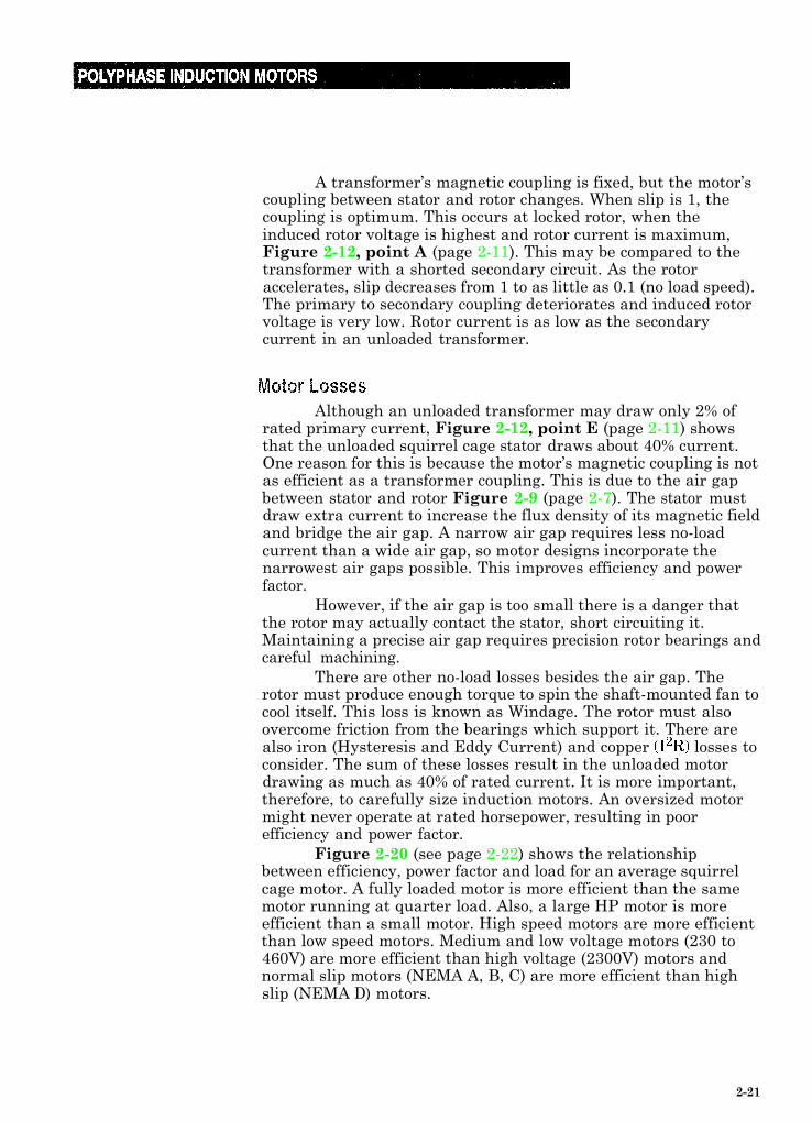
Figure 2-20 (see page 2-22) shows the relationshipbetween efficiency, power factor and load for an average squirrelcage motor. A fully loaded motor is more efficient than the samemotor running at quarter load. Also, a large HP motor is moreefficient than a small motor. High speed motors are more efficientthan low speed motors. Medium and low voltage motors (230 to460V) are more efficient than high voltage (2300V) motors andnormal slip motors (NEMA A, B, C) are more efficient than highslip (NEMA D) motors.
2-21
100
85
EFFICIENCY
0 25
Power Factor
IllI IIll III1
75 100 125
LOAD %
Figure 2-20
Effects of Voltage VariationsRecall from Equation 2-3 that torque is determined by
stator flux and rotor current, which result from rotor voltage. Fora given slip, rotor voltage is directly proportional to the density ofthe stator flux being cut. Stator flux is directly proportional tostator current (until the saturation level is reached). Therefore, ifthe motor’s applied frequency is held constant, stator current andflux will rise and fall in direct relation to the applied voltage.
Increased voltage yields higher flux density, which meansthat higher rotor voltages are induced at a given slip.
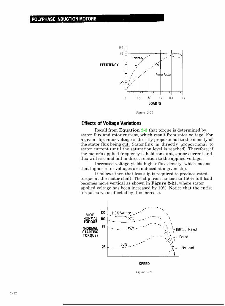
It follows then that less slip is required to produce ratedtorque at the motor shaft. The slip from no-load to 150% full loadbecomes more vertical as shown in Figure 2-21, where statorapplied voltage has been increased by 10%. Notice that the entiretorque curve is affected by this increase.
%OF
w!&
NORMAL4TARTINGTORQUE)
122
100
81
25
SPEED
Figure 2-21
2-22
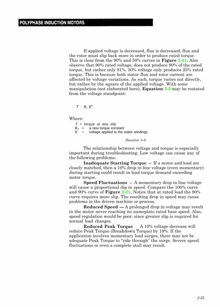
If applied voltage is decreased, flux is decreased, flux andthe rotor must slip back more in order to produce rated torque.This is clear from the 90% and 50% curves in Figure 2-21. Alsoobserve that 90% rated voltage, does not produce 90% of the ratedtorque, but rather only 81%. 50% voltage only produces 25% ratedtorque. This is because both stator flux and rotor current areaffected by voltage variations. As such, torque varies not directly,but rather by the square of the applied voltage. With somemanipulation (not elaborated here), Equation 2-3 may be restatedfrom the voltage standpoint:
Where:T = torque at any slipKt = a new torque constantE = voltage applied to the stator windings
(Equation 2-4)
The relationship between voltage and torque is especiallyimportant during troubleshooting. Low voltage can cause any ofthe following problems:
Inadequate Starting Torque - If a motor and load areclosely matched, then a 10% drop in line voltage (even momentary)during starting could result in load torque demand exceedingmotor torque.
Speed Fluctuations - A momentary drop in line voltagewill cause a proportional dip in speed. Compare the 100% curveand 90% curve of Figure 2-21. Notice that at rated load the 90%curve requires more slip. The resulting drop in speed may causeproblems in the driven machine or process.
Reduced Speed - A prolonged drop in voltage may resultin the motor never reaching its nameplate rated base speed. Also,speed regulation would be poor; since greater slip is required fornormal load changes.
Reduced Peak Torque - A 10% voltage decrease willreduce Peak Torque (Breakdown Torque) by 19%. If theapplication involves momentary load surges, there may not beadequate Peak Torque to “ride through” the surge. Severe speedfluctuations or even a complete stall may result.
2-23
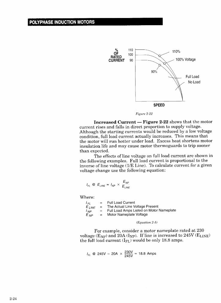
For example, consider a motor nameplate rated at 230voltage (ENP) and 20A (INP). If line is increased to 245V (ELI&the full load current (I& would be only 18.8 amps.
IFL @ 245V = 20A x g = 18.8 Amps
If line voltage is reduced to 208, then the full load currentwill increase to a value of 22 amps. When determining expectedmotor current, the following values are accurate within 20%. A30 squirrel cage motor operating at 230V draws 3 amps/HP. A460V motor draws 1.5 amps/HP and a 575V motor draws 1 amp/HPIn contrast, a single (21 motor at 115V draws 10A/HP and at 230Vdraws 5A/HP.
Using the effects of voltage variations on a motor can beused as an advantage. By limiting the voltage to the motor duringstarting, the current drawn and the torque produced by the motorcan be regulated. There are four different common methods forreduced voltage starting: Autotransformer, Wye-Delta(Star-Delta), Part Winding and Solid State.
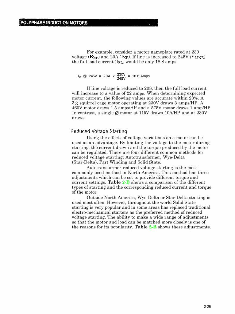
Autotransformer reduced voltage starting is the mostcommonly used method in North America. This method has threeadjustments which can be set to provide different torque andcurrent settings. Table 2-B shows a comparison of the differenttypes of starting and the corresponding reduced current and torqueof the motor.
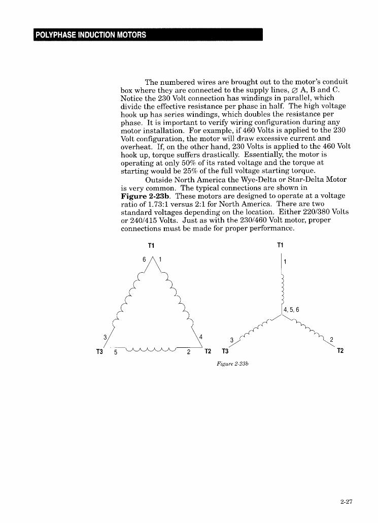
Outside North America, Wye-Delta or Star-Delta starting isused most often. However, throughout the world Solid Statestarting is very popular and in some areas has replaced traditionalelectro-mechanical starters as the preferred method of reducedvoltage starting. The ability to make a wide range of adjustmentsso that the motor and load can be matched more closely is one ofthe reasons for its popularity. Table 2-B shows these adjustments.
2-25
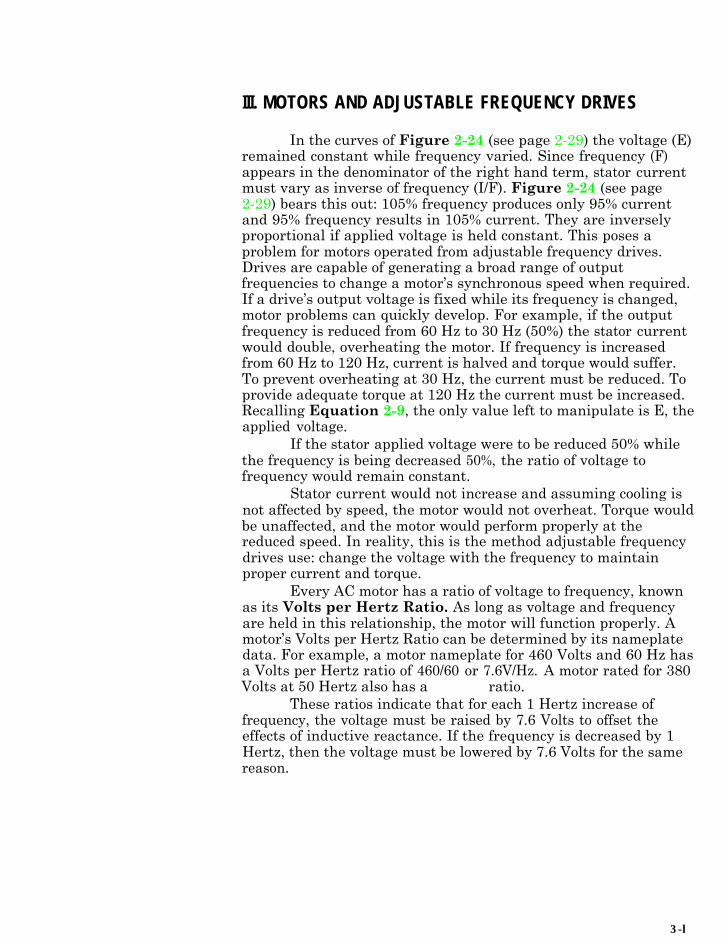
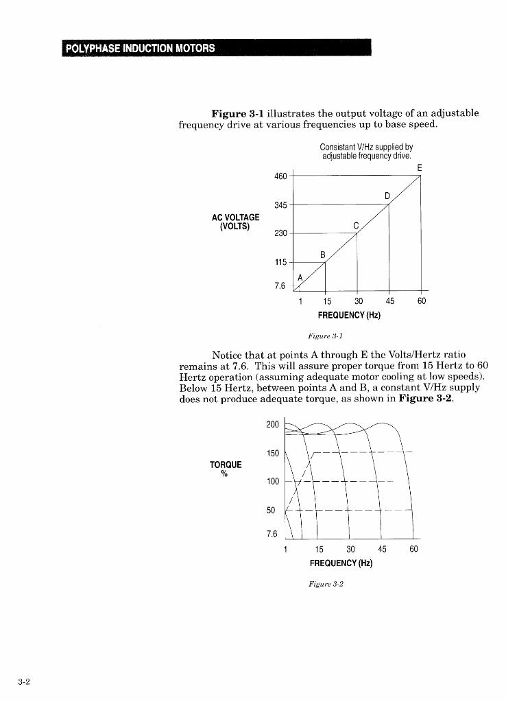
III. MOTORS AND ADJUSTABLE FREQUENCY DRIVES
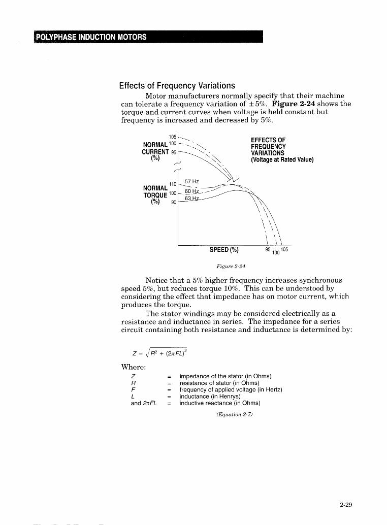
In the curves of Figure 2-24 (see page 2-29) the voltage (E)remained constant while frequency varied. Since frequency (F)appears in the denominator of the right hand term, stator currentmust vary as inverse of frequency (I/F). Figure 2-24 (see page2-29) bears this out: 105% frequency produces only 95% currentand 95% frequency results in 105% current. They are inverselyproportional if applied voltage is held constant. This poses aproblem for motors operated from adjustable frequency drives.Drives are capable of generating a broad range of outputfrequencies to change a motor’s synchronous speed when required.If a drive’s output voltage is fixed while its frequency is changed,motor problems can quickly develop. For example, if the outputfrequency is reduced from 60 Hz to 30 Hz (50%) the stator currentwould double, overheating the motor. If frequency is increasedfrom 60 Hz to 120 Hz, current is halved and torque would suffer.To prevent overheating at 30 Hz, the current must be reduced. Toprovide adequate torque at 120 Hz the current must be increased.Recalling Equation 2-9, the only value left to manipulate is E, theapplied voltage.
If the stator applied voltage were to be reduced 50% whilethe frequency is being decreased 50%, the ratio of voltage tofrequency would remain constant.
Stator current would not increase and assuming cooling isnot affected by speed, the motor would not overheat. Torque wouldbe unaffected, and the motor would perform properly at thereduced speed. In reality, this is the method adjustable frequencydrives use: change the voltage with the frequency to maintainproper current and torque.
Every AC motor has a ratio of voltage to frequency, knownas its Volts per Hertz Ratio. As long as voltage and frequencyare held in this relationship, the motor will function properly. Amotor’s Volts per Hertz Ratio can be determined by its nameplatedata. For example, a motor nameplate for 460 Volts and 60 Hz hasa Volts per Hertz ratio of 460/60 or 7.6V/Hz. A motor rated for 380Volts at 50 Hertz also has a 7.6V/Hz ratio.
These ratios indicate that for each 1 Hertz increase offrequency, the voltage must be raised by 7.6 Volts to offset theeffects of inductive reactance. If the frequency is decreased by 1Hertz, then the voltage must be lowered by 7.6 Volts for the samereason.
3-l
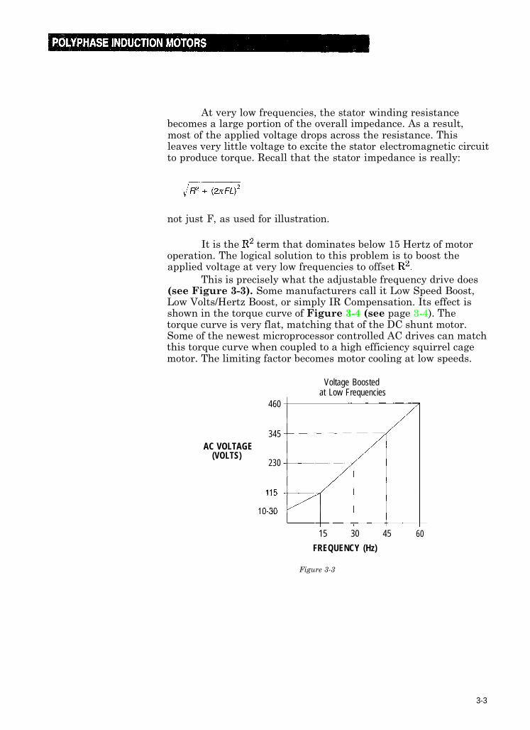
At very low frequencies, the stator winding resistancebecomes a large portion of the overall impedance. As a result,most of the applied voltage drops across the resistance. Thisleaves very little voltage to excite the stator electromagnetic circuitto produce torque. Recall that the stator impedance is really:
not just F, as used for illustration.
It is the R2 term that dominates below 15 Hertz of motoroperation. The logical solution to this problem is to boost theapplied voltage at very low frequencies to offset R2.
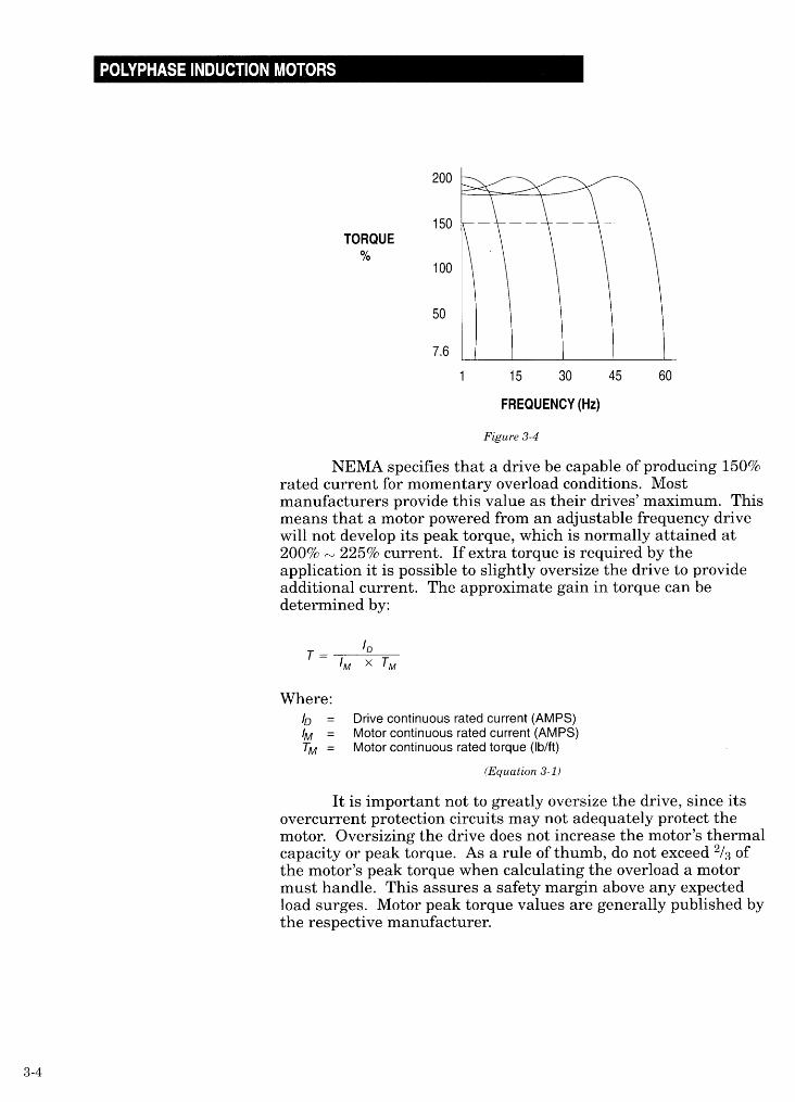
This is precisely what the adjustable frequency drive does(see Figure 3-3). Some manufacturers call it Low Speed Boost,Low Volts/Hertz Boost, or simply IR Compensation. Its effect isshown in the torque curve of Figure 3-4 (see page 3-4). Thetorque curve is very flat, matching that of the DC shunt motor.Some of the newest microprocessor controlled AC drives can matchthis torque curve when coupled to a high efficiency squirrel cagemotor. The limiting factor becomes motor cooling at low speeds.
460
Voltage Boostedat Low Frequencies
345AC VOLTAGE
(VOLTS)230
15 30 45
FREQUENCY (Hz)
60
Figure 3-3
3-3
When replacing line starter with an AC drive, the samemotor, wiring and conduits may be used. The drive may beremotely mounted as far as one mile from the motor forconvenience or safety. Sometimes the customer may retain the linestarter as a back-up system. In the event of a system malfunction,the line starter can bypass the drive to operate the motortemporarily. Bypass capability is a requirement in someapplications such as water treatment pumps or boiler pumps.Other drive methods (i.e. DC drives, eddy current clutches andhydraulic drives) are much more expensive to bypass. (Alwayscheck NEMA specifications and local codes to assure safe wiringpractices.)
Improved speed regulation is available with AC drives. Aline started squirrel cage motor will drop approximately 3% inspeed when fully loaded. By installing a tachometer on the motor,the AC drive can actively monitor motor speed and improve speedregulation to as high as 0.1%.
Operation AboveA motor rated for 60 Hz operation may be run at higher
frequencies when powered by an AC drive. The top speed dependsupon the voltage limits of the motor and its mechanical balancing.230V and 460V motors normally employ insulation rated for 600V,so the voltage limit is not usually a problem. An average 2 poleindustrial motor can safely exceed base speed by 25%. Manymanufacturers balance their 3 pole and 4 pole rotors to the samespeed - 25% over the 2 pole base speed. A 4 pole motor maytherefore operate up to 125% over base speed before reaching itsbalance limit. A 60 Hz 4 pole motor might run up to 135 Hz,whereas a 60 Hz 2 pole motor would reach its balance limit at 75Hz. Both motors would run at the same RPM. Naturally, it issound advice to consult the motor manufacturer before exceedingany motor’s base speed by more than 25%.
Constant Voltage OperationFigure 3-3 shows that at 60 Hz the AC drive’s output is
460 Volts, its maximum value. What happens if the outputfrequency is increased above 60 Hz while the voltage remains at460V? The drive’s Volts per Hertz ratio no longer remains constantand available torque decreases.
If output frequency is increased to 120 Hz with 100%voltage applied to the motor, the Volts per Hertz of the drive is nolonger 7.6 but rather 3.83. The same Volts per Hertz ratio resultswhen a line started motor is operated at 60 Hz with only 50%voltage applied (for reduced voltage starting). As might beexpected, the effect on torque is the same. Recall that torquevaries as the square of the applied voltage (Equation 2-4). Assuch, maximum motor torque at 120 Hz is only 25% of themaximum torque at 60 Hz.
3-6
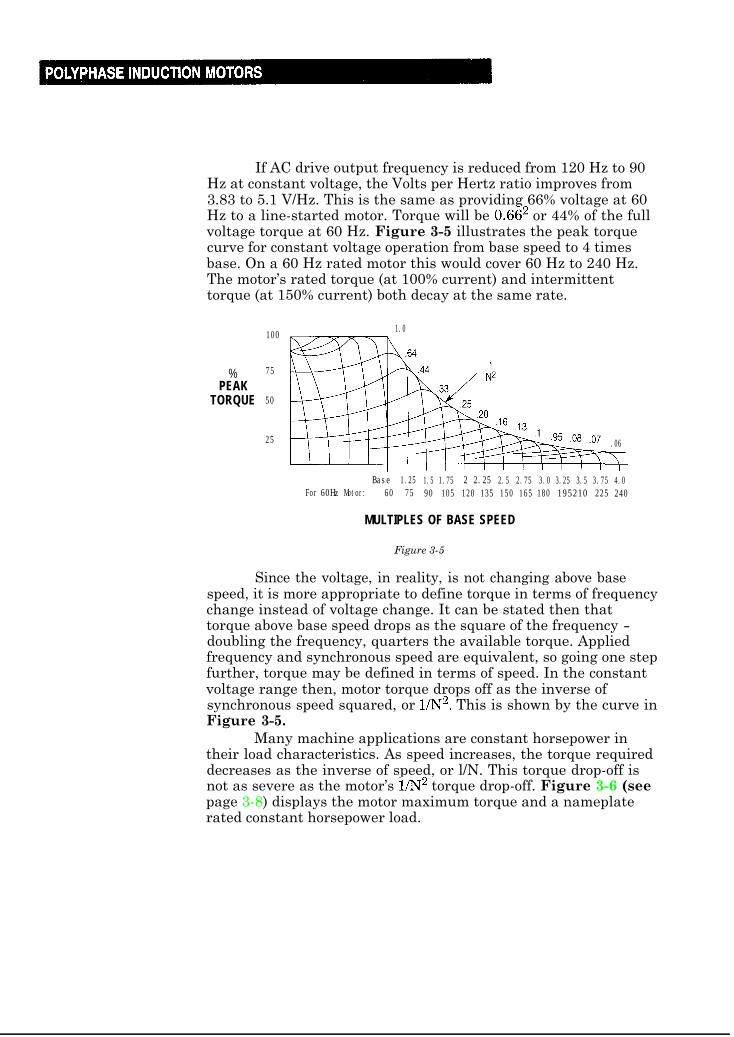
If AC drive output frequency is reduced from 120 Hz to 90Hz at constant voltage, the Volts per Hertz ratio improves from3.83 to 5.1 V/Hz. This is the same as providing 66% voltage at 60Hz to a line-started motor. Torque will be 0.662 or 44% of the fullvoltage torque at 60 Hz. Figure 3-5 illustrates the peak torquecurve for constant voltage operation from base speed to 4 timesbase. On a 60 Hz rated motor this would cover 60 Hz to 240 Hz.The motor’s rated torque (at 100% current) and intermittenttorque (at 150% current) both decay at the same rate.
%PEAK
TORQUE
100
75
50
25
1.0
.06
$Base 1.25 1.5 1.75 2 2.25 2.5 2.75 3.0 3.25 3.5 3.75 4.0
For 60Hz Motor: 60 75 90 105 120 135 150 165 180 195210 225 240
MULTIPLES OF BASE SPEED
Figure 3-5
Since the voltage, in reality, is not changing above basespeed, it is more appropriate to define torque in terms of frequencychange instead of voltage change. It can be stated then thattorque above base speed drops as the square of the frequency -doubling the frequency, quarters the available torque. Appliedfrequency and synchronous speed are equivalent, so going one stepfurther, torque may be defined in terms of speed. In the constantvoltage range then, motor torque drops off as the inverse ofsynchronous speed squared, or 1/N2. This is shown by the curve inFigure 3-5.
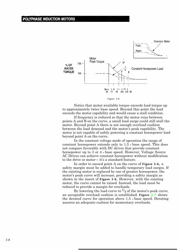
Many machine applications are constant horsepower intheir load characteristics. As speed increases, the torque requireddecreases as the inverse of speed, or l/N. This torque drop-off isnot as severe as the motor’s l/N2 torque drop-off. Figure 3-6 (seepage 3-8) displays the motor maximum torque and a nameplaterated constant horsepower load.
3-7
I Oversize Motor
Motor
Base 1.25 1.5 1.75 260 75 90 105 120 Hz
Figure 3-6
Notice that motor available torque exceeds load torque upto approximately twice base speed. Beyond this point the loadexceeds the motor capability and would cause a stall condition.
If frequency is reduced so that the motor runs betweenpoints A and B on the curve, a small load surge could still stall themotor. Beyond point A there is not enough overload cushionbetween the load demand and the motor’s peak capability. Themotor is not capable of safely powering a constant horsepower loadbeyond point A on the curve.
In the constant voltage mode of operation the range ofconstant horsepower extends only to 1.5 x base speed. This doesnot compare favorably with DC drives that provide constanthorsepower up to 3 or 4 x base speed. However, Voltage SourceAC Drives can achieve constant horsepower without modificationto the drive or motor - it’s a standard feature.
In order to exceed point A on the curve of Figure 3-6, asafety margin must be added to handle temporary load surges. Ifthe existing motor is replaced by one of greater horsepower, themotor’s peak curve will increase, providing a safety margin asshown in the insert of Figure 3-6. However, with the existingmotor, the curve cannot be raised. Instead, the load must bereduced to provide a margin for overloads.
By lowering the load curve to 2/3 of the motor’s peak curve,an acceptable overload cushion is established. Figure 3-7 showsthe derated curve for operation above 1.5 x base speed. Deratingassures an adequate cushion for momentary overloads.
3-8
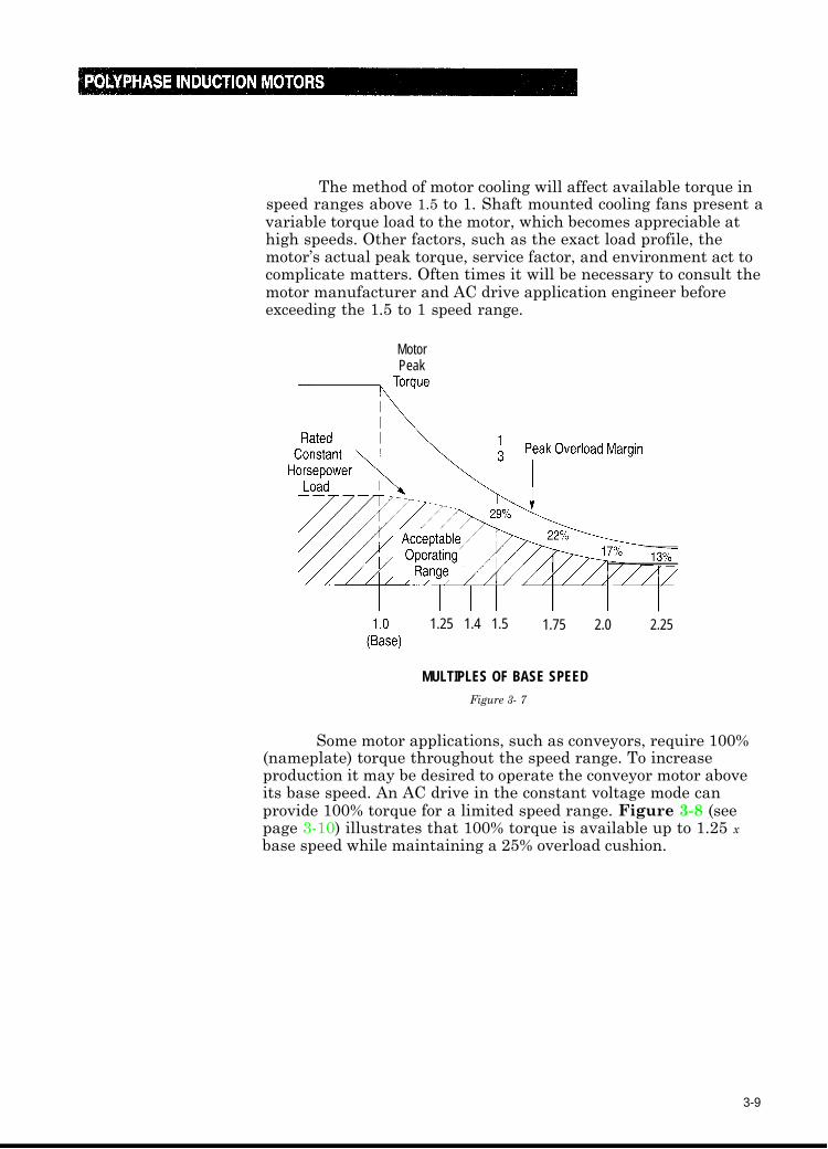
The method of motor cooling will affect available torque inspeed ranges above 1.5 to 1. Shaft mounted cooling fans present avariable torque load to the motor, which becomes appreciable athigh speeds. Other factors, such as the exact load profile, themotor’s actual peak torque, service factor, and environment act tocomplicate matters. Often times it will be necessary to consult themotor manufacturer and AC drive application engineer beforeexceeding the 1.5 to 1 speed range.
MotorPeak
1.25 1.4 1.5 1.75 2.0 2.25
MULTIPLES OF BASE SPEED
Figure 3- 7
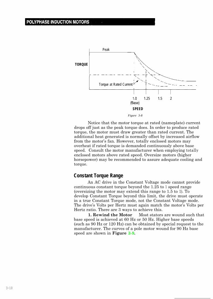
Some motor applications, such as conveyors, require 100%(nameplate) torque throughout the speed range. To increaseproduction it may be desired to operate the conveyor motor aboveits base speed. An AC drive in the constant voltage mode canprovide 100% torque for a limited speed range. Figure 3-8 (seepage 3-10) illustrates that 100% torque is available up to 1.25 x
base speed while maintaining a 25% overload cushion.
3-9
Peak
TORQUE
Torque at Rated Current
1.25 1.5 2
SPEED
Figure 3-8
Notice that the motor torque at rated (nameplate) currentdrops off just as the peak torque does. In order to produce ratedtorque, the motor must draw greater than rated current. Theadditional heat generated is normally offset by increased airflowfrom the motor’s fan. However, totally enclosed motors mayoverheat if rated torque is demanded continuously above basespeed. Consult the motor manufacturer when employing totallyenclosed motors above rated speed. Oversize motors (higherhorsepower) may be recommended to assure adequate cooling andtorque.
Constant Torque RangeAn AC drive in the Constant Voltage mode cannot provide
continuous constant torque beyond the 1.25 to 1 speed range(oversizing the motor may extend this range to 1.5 to 1). Todevelop Constant Torque beyond this limit, the drive must operatein a true Constant Torque mode, not the Constant Voltage mode.The drive’s Volts per Hertz must again match the motor’s Volts perHertz ratio. There are 3 ways to achieve this.
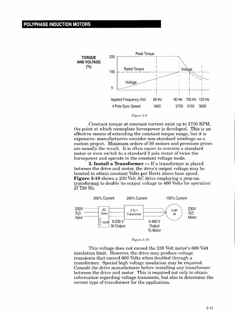
1. Rewind the Motor - Most stators are wound such thatbase speed is achieved at 60 Hz or 50 Hz. Higher base speeds(such as 90 Hz or 120 Hz) can be obtained by special request to themanufacturer. The curves of a pole motor wound for 90 Hz basespeed are shown in Figure 3-9.
3-10
AC drives do not produce sinuosidal voltages, but rathergenerate square wave or pulses of voltage, which would saturateand destroy a standard transformer. Special purpose customdesigned transformers are therefore essential for proper operation.These transformers become quite expensive, approaching orexceeding the price of a small AC drive. It may not be economicalto install such a transformer on small drive applications.
On larger applications output transformers are sometimesused to match low voltage drive to a high voltage motor. This isdone in the petrochemical industry where the output voltage of a460V AC drive may be stepped up to operate a 2300 Volt pumpmotor from zero to its base speed. The price of such a transformerwas motivation for the development of high voltage semiconductorsfor the output stages of AC drives.
Notice in Figure 3-10 (see page 3-11) that the step-uptransformer halves the current while doubling voltage. To supply100% (nameplate) current to the motor, the drive must produce200% current at its output. The AC drive must be doubled in size:a 10 HP drive is needed to power the 5 HP motor for constanttorque up to 120 Hz. If the range is reduced to 90 Hz, a 7l/2 HPdrive would provide rated current at the motor. This is becausethe transformer’s winding ratio would be changed from 2 to 1 to1.5 to 1.
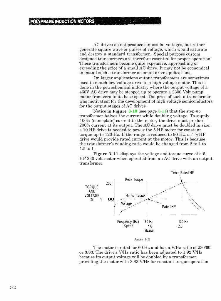
Figure 3-11 displays the voltage and torque curve of a 5HP 230 volt motor when operated from an AC drive with an outputtransformer.
Twice Rated HP
200TORQUE
ANDVOLTAGE
(%) 1 00
Peak Torque
Frequency (Hz) 60 HZ 120 HzSpeed 2.0
Figure 3-11
The motor is rated for 60 Hz and has a V/Hz ratio of 230/60or 3.83. The drive’s V/Hz ratio has been adjusted to 1.92 V/Hzbecause its output voltage will be doubled by a transformer,providing the motor with 3.83 V/Hz for constant torque operation.
3-12
At 60 Hz the motor receives 230 Volts and produces 5 HPwhen fully loaded. At 120 Hz the motor voltage is 460 Volts. Sinceboth voltages and frequency are doubled, the V/Hz ratio remains at3.83 and rated torque may be obtained. Increased motor losses atthe high speed and frequency will cause the motor to draw greaterthan rated current to produce rated torque. However, the motor isnot over or under voltaged and will perform properly, producing 10HP at 120 Hz. This justifies the 10 HP drive required to assureadequate current. Still, the oversize drive and transformerincrease the price of a system significantly, normally making ituneconomical. In addition, the step-up transformer limits theavailable torque at low frequencies, limiting the range of constanttorque. This occurs because the transformer may saturate andoverheat at low frequencies, demanding that the current (andtorque) be reduced. The third method of producing constant torqueabove rated speed is more practical.
3. Use a 460V Drive for a 230 Volt Motor - The curvesof Figure 3-11 may be obtained without placing a transformerbetween the drive and motor if the drive can produce 460 Voltsdirectly at its output. The drive’s V/Hz ratio must be set at 3.83 toaccommodate a 230 volt motor. Also, since a 230 volt motor drawstwice the current of a 460 volt motor of equal horsepower, the ACdrive must double in size.
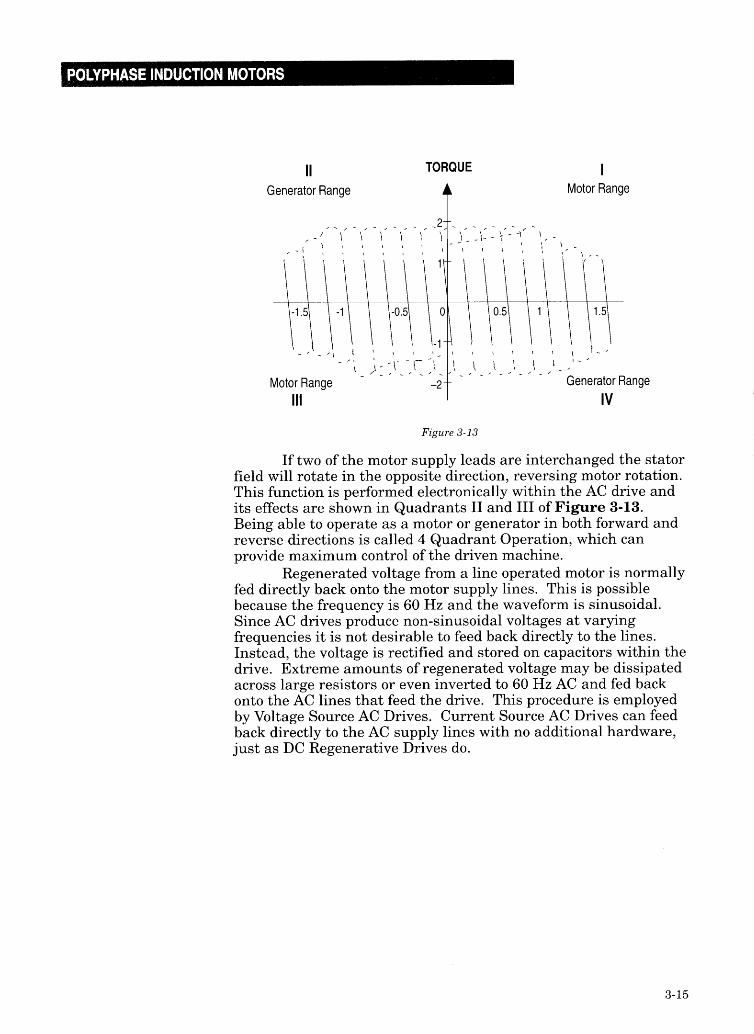
As current flows through the stator and rotor a countervoltage is generated, just as in a transformer. The counter voltageopposes the applied voltage and acts to limit motor current.Normally the applied voltage exceeds the counter voltage andpower is supplied to the motor. However, if the counter voltageexceeds the applied voltage, the motor will effectively become agenerator and feed power back onto the supply lines. Thegenerated power will be at the same voltage and frequency as thesupply and the motor’s power factor will be leading instead oflagging. The magnitude of generated power is dependent on thedifference between applied voltage and the counter voltage.
During normal operation, motor synchronous speed exceedsthe running speed by the amount of slip as shown by point A inFigure 3-12 (see page 3-14). If the load overhauls the motor (pullsthe rotor faster than synchronous speed), slip reverses. The rotorbars begin to cut the stator field from the opposite direction, whichreverses the polarity of rotor voltage. Rotor counter voltage thenexceeds the rotor induced voltage and produces a larger voltage ofmutual inductance in the stator windings. This voltage is thesame polarity as stator counter voltage and results in a net voltagepolarity reversal, feeding power back to the supply lines.
3-13
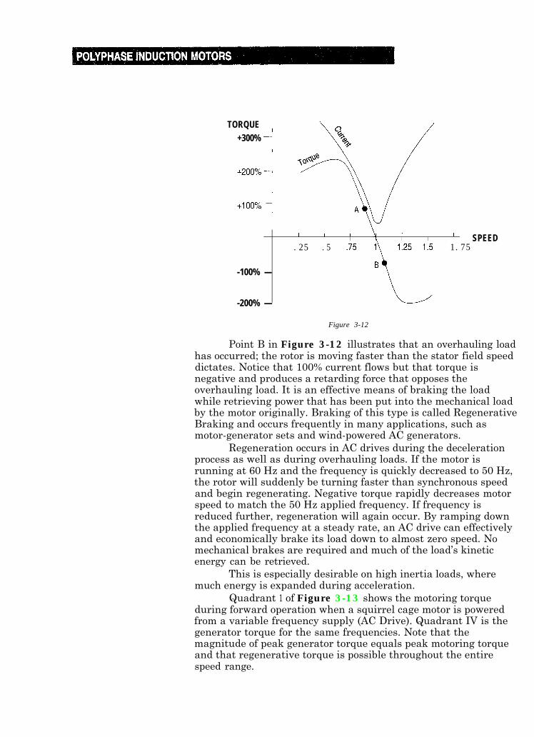
TORQUE+300%
I I I \I I I I SPEED.25 .5 1.75
-100% -
-200% -
Figure 3-12
Point B in Figure 3-12 illustrates that an overhauling loadhas occurred; the rotor is moving faster than the stator field speeddictates. Notice that 100% current flows but that torque isnegative and produces a retarding force that opposes theoverhauling load. It is an effective means of braking the loadwhile retrieving power that has been put into the mechanical loadby the motor originally. Braking of this type is called RegenerativeBraking and occurs frequently in many applications, such asmotor-generator sets and wind-powered AC generators.
Regeneration occurs in AC drives during the decelerationprocess as well as during overhauling loads. If the motor isrunning at 60 Hz and the frequency is quickly decreased to 50 Hz,the rotor will suddenly be turning faster than synchronous speedand begin regenerating. Negative torque rapidly decreases motorspeed to match the 50 Hz applied frequency. If frequency isreduced further, regeneration will again occur. By ramping downthe applied frequency at a steady rate, an AC drive can effectivelyand economically brake its load down to almost zero speed. Nomechanical brakes are required and much of the load’s kineticenergy can be retrieved.
This is especially desirable on high inertia loads, wheremuch energy is expanded during acceleration.
Quadrant 1 of Figure 3-13 shows the motoring torqueduring forward operation when a squirrel cage motor is poweredfrom a variable frequency supply (AC Drive). Quadrant IV is thegenerator torque for the same frequencies. Note that themagnitude of peak generator torque equals peak motoring torqueand that regenerative torque is possible throughout the entirespeed range.
3-14
The energy efficient motor differs from a standard motor inboth design and manufacturing techniques. It is not, as somesuppose, a return to the old U frame motors of the past.
First of all, the energy efficient motor employs larger statorconductors with higher conductivity. The rotor bars are larger aswell, to reduce the overall copper (or aluminum) loss whichcomprises 55-60% of total motor losses. The motor flux densityand air gap are reduced to minimize the magnetizing currentrequired. Stator and rotor laminations are thinner to increaseresistance to the flow of eddy currents. More laminations areadded to the core stacks as well, producing a longer stator androtor for increased torque. Hysteresis losses, which are normally20-25% of the total motor losses, are reduced by utilizing siliconsteel, instead of low carbon steel for the laminations. As a result,the motor uses less current, has better power factor, and runscooler.
Since the energy efficient motor runs cooler, ventilationrequirements are reduced, allowing a smaller fan to be installed.Windage loss (typically 5-9% of total losses) decreases and thesmaller fan runs quieter. These motors are less susceptible todamage from impaired ventilation and operate well at higheraltitudes also. Cooler operation also increases motor life.Insulation life is up to 4 times longer, an important fact, sinceinsulation break-down is the number 1 cause of motor failures.Bearing lubrication lasts longer too, doubling the interval betweenrequired lubrication. Cooler operation means that less burden isplaced on air conditioning equipment, (The Textile Industry usesmany squirrel cage motors in air conditioned factories.) Energyefficient motors can also operate in higher ambient temperatureswithout requiring extra cooling. A standard motor may needadditional cooling to survive in the same environment. This couldadd substantially to the purchase price of the motor.
Energy efficient motors are also more rugged than standardmotors, tolerating greater fluctuations in applied voltage, voltageunbalance, and overload.
Some manufacturer’s line of energy efficient motors allpossess 1.15 service factors. Some can even tolerate 30-40%overloads for prolonged periods. They are also capable of startinghigher inertia loads than standard motors because of theirincreased thermal capacity. For example, manufacturer’s standard50 HP motor can accelerate a maximum inertia of 597 lb ft’ whilean ener
57efficient model can accelerate an inertia load as high as
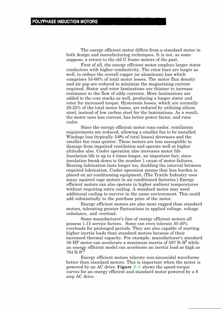
764 lb ft .Energy efficient motors tolerate non-sinusoidal waveforms
better than standard motors. This is important when the motor ispowered by an AC drive. Figure 4-1 shows the speed-torquecurves for an energy efficient and standard motor powered by a 6step AC drive.
4-2
%LOAD
--w---- $/!$+
Resistant
\
Current
1’5 ;o $0 160
FREQUENCY (HZ)
Figure 4-l
Notice that the standard motor has been derated to 85%.This is due to the heating caused by the waveform shown in theright corner. To provide the same performance as the energyefficient motor, a larger standard motor is required. No derating isrequired on the energy efficient motor, since it can tolerate thedisturbances caused by the 6 step waveform. Other types of ACdrives produce smoother waveforms that would not requirederating of the standard motor. One such type is the PWM (PulseWidth Modulated) AC drive.
Energy efficient motors prove most cost effective inapplications where:l The cost of electricity is high. The higher the power rate, the
greater potential for savings.
l The customer is concerned about power factor penalties andpeak demand charges.
l Loads are constant, allowing accurate projection of potentialsavings.
l Excessive heating is expected, either from high ambientconditions or severe duty cycle.
l Running time exceeds idle time, again increasing savings.
l Larger horsepower motors are involved, since they consumemore power and represent greater savings potentials.
4-3
V. SPECIAL MOTORS
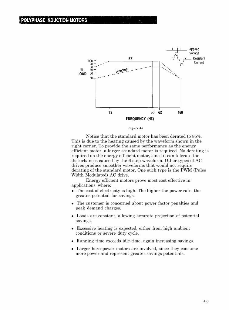
The Wound Rotor Motor is an induction motor that permitsvariable speed operation without the use of an AC drive. Themotor’s stator is identical to that of the standard polyphasesquirrel cage motor, but its rotor differs considerably. The rotor isnot of cast aluminum or copper bars, but rather consists ofinsulated coils of wire connected in regular succession to formdefinite poles (the same number as the stator poles). The ends ofthese rotor windings are brouht out to slip rings mounted on themotor shaft. Carbon brushes ride the slip rings to connect therotor windings to an external resistor network.
Figure 5-l shows the controller, which allows adjustmentof the rotor resistance. By varying rotor resistance, the torque andcurrent characteristics can be changed. For example, highresistance would produce high starting torque at low current,similar to a NEMA D motor. As the motor accelerates, resistancecan be reduced to simulate a NEMA A motor. The result ishigh starting torque, smooth acceleration, and optimum efficiencyat running speeds.
External
T1 T2 T3
on Rotor
Figure 5-l
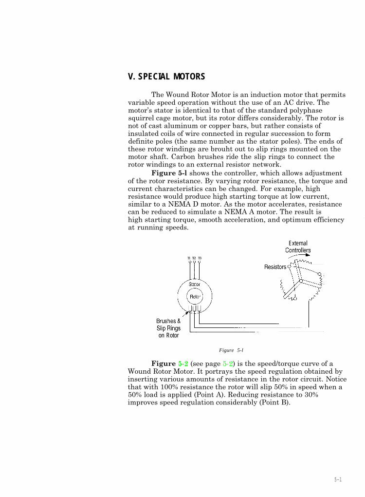
Figure 5-2 (see page 5-2) is the speed/torque curve of aWound Rotor Motor. It portrays the speed regulation obtained byinserting various amounts of resistance in the rotor circuit. Noticethat with 100% resistance the rotor will slip 50% in speed when a50% load is applied (Point A). Reducing resistance to 30%improves speed regulation considerably (Point B).
5-l
260250240230220210200190180170160
% 150
FULL 140130
LOAD 120TORQUE 110
100908070605040302010
0 10 20 30 40 50 60 70 80 90 100
SPEED % OF SYNCHRONOUS
Figure 5-2
A means of variable speed operation is achieved with theWound Rotor Motor. Unfortunately, the motor’s efficiencydecreases in direct proportion to the speed reduction desired.Because of this, the wound rotor motor is most often used oncranes, hoists and elevators, where exact speed regulation andefficiency are not important. Efficiency may be improved by theinstallation of a slip recovery system in the rotor circuit. Basically,the external resistances are replaced by a solid state converterwhich feeds the excess rotor power back to the supply lines.
Another type of special motor is the ReluctanceSynchronous Motor. It again uses the same stator assembly as astandard squirrel cage motor and differs only in rotor construction.Figure 5-3 shows a rotor punching used in a typical ReluctanceSynchronous Motor.
5-2
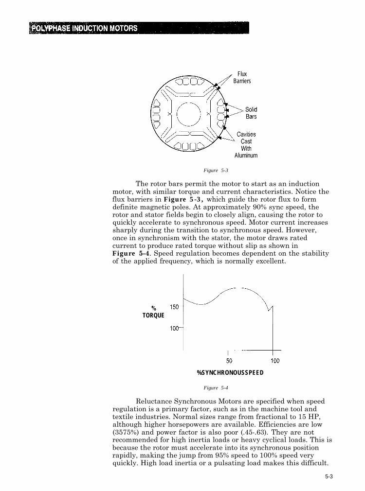
FluxBarriers
Aluminum
Figure 5-3
The rotor bars permit the motor to start as an inductionmotor, with similar torque and current characteristics. Notice theflux barriers in Figure 5-3, which guide the rotor flux to formdefinite magnetic poles. At approximately 90% sync speed, therotor and stator fields begin to closely align, causing the rotor toquickly accelerate to synchronous speed. Motor current increasessharply during the transition to synchronous speed. However,once in synchronism with the stator, the motor draws ratedcurrent to produce rated torque without slip as shown inFigure 5-4. Speed regulation becomes dependent on the stabilityof the applied frequency, which is normally excellent.
TORQUE
%SYNCHRONOUSSPEED
Figure 5-4
Reluctance Synchronous Motors are specified when speedregulation is a primary factor, such as in the machine tool andtextile industries. Normal sizes range from fractional to 15 HP,although higher horsepowers are available. Efficiencies are low(3575%) and power factor is also poor (.45-.63). They are notrecommended for high inertia loads or heavy cyclical loads. This isbecause the rotor must accelerate into its synchronous positionrapidly, making the jump from 95% speed to 100% speed veryquickly. High load inertia or a pulsating load makes this difficult.
5-3

Publication 150-2.7 December 1998 Copyright 1998 Rockwell International Printed in USA