Embed Size (px)
Citation preview
1
MOTORCYCLE CHASSIS ANALYSIS
Diogo Rechena ([email protected])a; Luís Sousa ([email protected])a; Luís Eça ([email protected])a;
aIDMEC/IST, Institute of Mechanical Engineering, Instituto Superior Técnico, University of Lisbon, Portugal
Abstract
This paper is intended to provide an overview of a chassis for the future motorcycle PR7 for the AJP brand. With this
purpose loads and safety factors will be estimated for later use in several structural analysis. The several components will be
analysed separately instead of as a whole and, in some cases, the reaction forces in boundary areas of some parts will be used as
external loads in other ones. The structural analysis will be comprised of static simulations for all the components and buckling
analysis for parts under compressive loads. The method applied for this structural analysis will be the finite element method in
the SolidWorks 2014 software whose CAD functions will also be used in order to provide alternate geometries for the
motorcycle.
Keywords: Buckling, CAD, CAE, Chassis, Finite Element Method, Structural Analysis
1 Introduction
1.1 The Company, AJP
Founded in 1987 by António Pinto, AJP came out
with its first endure motorcycle, ARIANA 125cc. Since then,
the brand has participated in the National Championship great
success including five consecutive championships between
1996 and 2000. Since then, the brand has released three more
models, all in the 125cc and 250cc categories of dual sport
motorcycles [1].
1.2 Dual Sport Motorcycles
Dual Sport motorcycles are a type of PTW vehicle
that are fit to drive on and off road needing only different
tunings to adapt to different trails although certain
characteristics are more fit to drive on asphalt than on dirt such
as higher weight, lower and wider seats and more city oriented
tyres [2].
1.3 Modelling Motorcycle Chassis
1.3.1 Yielding, Buckling and Fatigue
Metallic alloys have a distinct behaviour
characterized by a plastic behaviour preceded by an elastic
one. Usually, structures are intended to work under elastic
behaviour, which means that the yield stress must not be
exceeded. To analyse if the stresses don’t exceed the yielding
threshold the Von Mises criterion.
𝑆𝑦
𝑛≥ √
(𝜎𝑥𝑥 − 𝜎𝑦𝑦)2 + (𝜎𝑥𝑥 − 𝜎𝑧𝑧)2 + (𝜎𝑦𝑦 − 𝜎𝑧𝑧)2 + 6(𝜎𝑥𝑦2 + 𝜎𝑥𝑧
2 + 𝜎𝑦𝑧2 )
2 (1)
Usually in mechanical engineering, structures aren’t
under static loads, which means fatigue analysis must be
performed in order to ensure that cracks are propagating in a
controlled rate, which is critical mainly on aluminium alloys.
Still, due to the fact that there isn’t enough data about the
metals, fatigue will only be taken into consideration as a way
of evaluating details on the geometry [3].
Also associated with dynamic loads is the buckling
phenomenon which occurs in this geometries when the applied
loads suffer perturbations leading to high displacement
deformations resulting in structural collapse. These
phenomena can’t be analysed with a static analysis which leads
to buckling simulations [4].
1.3.2 Triangulation
Motorcycle chassis are usually frame structures,
which means they sustain deformation and their configuration
affects deeply the stiffness of the global structure. Triangulated
frames come up as a solution to the deformation problem since
the geometry tends to convert bending loads into axial loads
leading to stiffer and lighter structures [5].
1.3.3 Structural Engine
With high displacement engines a typical solution is
to use the engine itself as a structural element supporting both
the steering column and the rear suspension.
1.3.4 Backbone Frames
This type of frame is usually light, connecting the
steering column to the back of the frame using a beam which
allows for a relatively stiff structures. The disadvantage of this
type of frame is that it can’t usually be fitted with bulky
engines.
1.3.5 Twin-spar Frames
This type of frame is usually used in track
motorcycles allowing for the accommodation of the air filter
which leads to heavier structures but that can also withstand
very high loads (in comparison to other frames).
2 Modelling the Problem
2.1 Determining External Loads
Since the frame is for a new motorcycle and its
conception is still in an early stage the external loads are still
uncertain. Still there are similar motorcycles that can provide
an estimate for the normal reactions on the wheels so an
XT660X was used to estimate these loads. Also, according to
[6] the motorcycle must be able to withstand a total of 186kg
of occupants, cargo and accessories. Also, according to [5] the
friction coefficient, µ, can reach a maximum value of 1.3
which results in the loads estimated in Table 1.
2
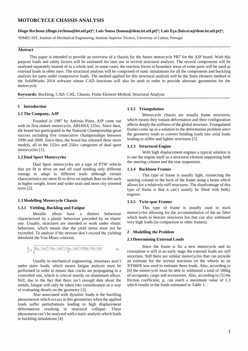
Fig. 1 – Weighing aa wheel to obtain the reaction value
Table 1 – Loads applied on the motorcycle wheels
Wheel Reaction (N) Maximum Friction Force (N)
Front 1500 1750
Back 2500 3250
2.2 Safety Factor
The safety factor was estimated using the Pugsley method,
which consists of using several empirical data such as the
material quality or the economic impact if failure occurs,
yielding two components of the safety factor 𝑛𝑠𝑥 and 𝑛𝑠𝑦 of
1.3 and 1.4, respectively, resulting in a project safety factor of
1.82.
Using the material properties of the chosen alloys and the
project safety factor the (Table 2) was created.
Table 2 – Material properties
Material 𝐸 [𝐺𝑃𝑎] ν 𝑆𝑦 [𝑀𝑃𝑎] 𝑆𝑈𝑇𝑆 [𝑀𝑃𝑎] 𝜎𝑎𝑑𝑚 [𝑀𝑃𝑎]
Al 69 0.33 165 250 90
Steel 200 0.29 235 370 129
3 Numerical Analysis and Convergence
In this chapter a convergence analysis will be
performed on a loaded component in order to establish the
stress and factor of safety precision that will be applied during
the analysis of the chassis’ several parts.
There are two possible meshing methods present in
the SolidWorks software, the standard mesh and the curvature-
based one. Both these meshes are going to be tested on the
swing arm’s connecting rod when subject to a given load.
Table 3 – Changes in stresses with element size variation
Change in mesh size
(mm) 1 -1.75 1.75 - 2.5 2.5 - 3.75 3.75 - 5
Curvature-based 0.59% 0.19% -1.09% -0.17%
Standard -0.40% -1.13% -1.05% -3.12%
Table 4 – Changes in FOS with element size variation
Change in mesh size
(mm) 1 -1.75 1.75 - 2.5 2.5 - 3.75 3.75 - 5
Curvature-based 35.63% 44.73% -1.93% -12.55%
Standard 51.14% 23.24% 23.89% 15.85%
As indicated in Table 3 and Table 4 the curvature-
based mesh tends to converge faster than the standard mesh.
This is due to the fact that the curvature-based mesh creates
elements in circular areas such as holes. Still there are zones
where it is not expected to achieve convergence such as
corners where the stresses are supposed to tend to infinity,
which results in the behaviour shown in (Fig. 2) in which
stresses increase in each iteration of mesh refinement.
Fig. 2 – Corner stresses in swingarm subject to a 5kN load
4 Initial Geometry Analysis
From the initial geometry, seven subsets were
analysed, being these the frontal zone of the frame, which
consists of the front suspension (considered a rigid body), the
steering column, the oil tank, and the engine’s cradle, the
swing arm, the engine head’s support, the swing arm’s rod, the
frame’s rod, the backbone and, finally the external beams.
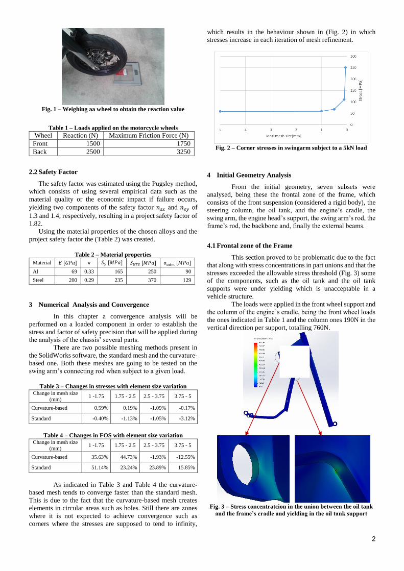
4.1 Frontal zone of the Frame
This section proved to be problematic due to the fact
that along with stress concentrations in part unions and that the
stresses exceeded the allowable stress threshold (Fig. 3) some
of the components, such as the oil tank and the oil tank
supports were under yielding which is unacceptable in a
vehicle structure.
The loads were applied in the front wheel support and
the column of the engine’s cradle, being the front wheel loads
the ones indicated in Table 1 and the column ones 190N in the
vertical direction per support, totalling 760N.
Fig. 3 – Stress concentratcion in the union between the oil tank
and the frame’s cradle and yielding in the oil tank support

3
Along with the structural problems, some other issues
arose such as the manufacturing of the component. The cradle
is made from the union of several beams with welding
processes. The current design may cause problems during the
welding due to misalignment of components as shown in Fig.
4.
Fig. 4 – Union between the lower beams and the cradle column
After FEA the reactions on the oil tank supports were
registered, in order to be used as boundary conditions in the
backbone analysis, in Table 5 (Fig. 5).
Fig. 5 – Supports in the oil tank
Table 5 – Reaction Forces in the oil tank’s supports
x (N) y (N) z (N)
Support 1 202.39 -1721.6 5885
Support 2 -276.3 1693.3 -6651.6
Support 3 206.02 -1711.3 5860.6
Support 4 279.81 1689.2 -6623.6
4.2 Swing Arm
The swing arm (Fig. 6) is a part that connects the rear
wheel to the frame and the rear suspension through the swing
arm’s rod and the frame’s rod. To model the loads on this
component it was considered that these were applied with the
swing arm in the horizontal position in which the bending
loads are maximum. After analysis three stress concentration
areas were found, two on the swing arm’s rod connection and
the other one bellow the referred support as shown in Fig. 7.
Fig. 6 – Swing arm connected to its rods
Fig. 7 – Stresses in the swingarm
The most problematic zone is the one in the upper left
corner of the support in Fig. 7 since it’s manufactured through
a milling process in order to generate a corner-like geometry.
Still the minimum safety factor is 3.28 (Fig. 8) with a
maximum stress of 50MPa. Another factor to take into
consideration is buckling, since this component may be subject
to compressive loads due to friction forces on the back wheel.
Fig. 8 – Buckling collapse zone for the 4th buckling mode
As shown in Fig. 8 the critical zone is below the
swing arm’s rod which may prove problematic if mass
reducing operations are applied (such as thickness reduction).
Still, the minimum positive safety factor for buckling is 52.26
and corresponds to the fourth buckling mode.
4.3 Engine Head’s Support
This component (Fig. 9) has the objective of partially
supporting the engine’s weight. Due to modelling
4
uncertainties, it was considered that the motorcycle’s weight
was applied in the engine and that it was equally divided by all
of its supports.
After analysis it was confirmed that this component
resists yielding since its minimum safety factor is of 5.18 (45
MPa of maximum stress) located in the link to the backbone
as shown in Fig. 10.
Fig. 9 – Engine Head’s Support
Fig. 10 – Stress concentration in the Engine Head’s Support
After analysis the reactions on the links were
registered to be used later for the backbone analysis.
Table 6 – Reaction loads on the engine head’s support
x(N) y(N) z(N)
Support 1 -12.34 288.78 0.07
Support 2 12.34 91.24 -0.03
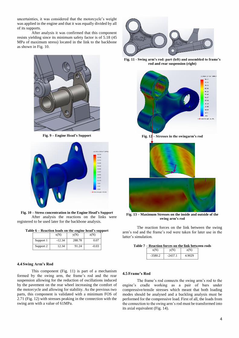
4.4 Swing Arm’s Rod
This component (Fig. 11) is part of a mechanism
formed by the swing arm, the frame’s rod and the rear
suspension allowing for the reduction of oscillations induced
by the pavement on the rear wheel increasing the comfort of
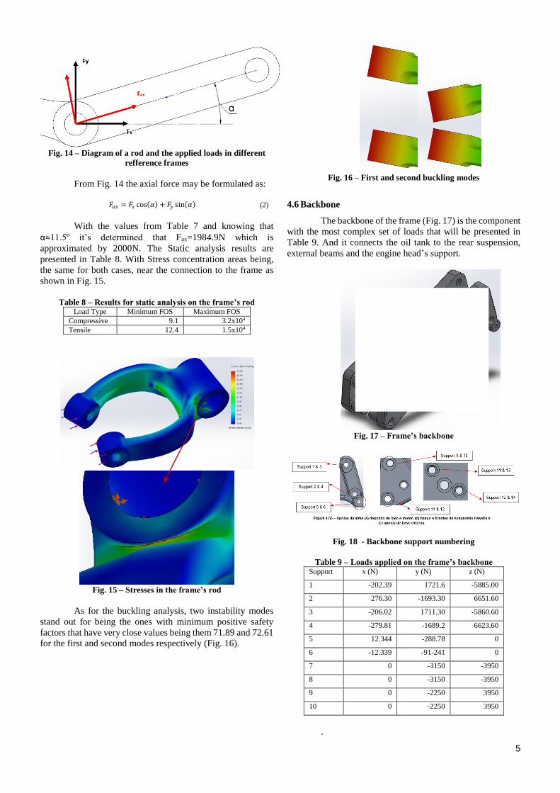
the motorcycle and allowing for stability. As the previous two
parts, this component is validated with a minimum FOS of
2.71 (Fig. 12) with stresses peaking in the connection with the
swing arm with a value of 61MPa.
Fig. 11 - Swing arm’s rod: part (left) and assembled to frame’s
rod and rear suspension (right)
Fig. 12 – Stresses in the swingarm’s rod
Fig. 13 – Maximum Stresses on the inside and outside of the
swing arm’s rod
The reaction forces on the link between the swing
arm’s rod and the frame’s rod were taken for later use in the
latter’s simulation.
Table 7 – Reaction forces on the link between rods
x(N) y(N) z(N)
-3580.2 -2437.1 4.9029
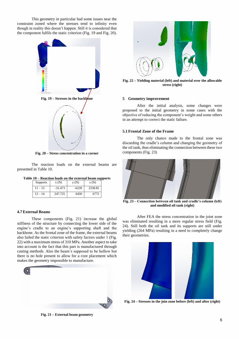
4.5 Frame’s Rod
The frame’s rod connects the swing arm’s rod to the
engine’s cradle working as a pair of bars under
compressive/tensile stresses which meant that both loading
modes should be analysed and a buckling analysis must be
performed for the compressive load. First of all, the loads from
the connection to the swing arm’s rod must be transformed into
its axial equivalent (Fig. 14).
5
Fig. 14 – Diagram of a rod and the applied loads in different
refference frames
From Fig. 14 the axial force may be formulated as:
𝐹𝑎𝑥 = 𝐹𝑥 cos(𝛼) + 𝐹𝑦 sin(𝛼) (2)
With the values from Table 7 and knowing that
α≈11.5º it’s determined that Fax=1984.9N which is
approximated by 2000N. The Static analysis results are
presented in Table 8. With Stress concentration areas being,
the same for both cases, near the connection to the frame as
shown in Fig. 15.
Table 8 – Results for static analysis on the frame’s rod
Load Type Minimum FOS Maximum FOS
Compressive 9.1 3.2x10⁴
Tensile 12.4 1.5x10⁴
Fig. 15 – Stresses in the frame’s rod
As for the buckling analysis, two instability modes
stand out for being the ones with minimum positive safety
factors that have very close values being them 71.89 and 72.61
for the first and second modes respectively (Fig. 16).
Fig. 16 – First and second buckling modes
4.6 Backbone
The backbone of the frame (Fig. 17) is the component
with the most complex set of loads that will be presented in
Table 9. And it connects the oil tank to the rear suspension,
external beams and the engine head’s support.
Fig. 17 – Frame’s backbone
Fig. 18 - Backbone support numbering
Table 9 – Loads applied on the frame’s backbone
Support x (N) y (N) z (N)
1 -202.39 1721.6 -5885.00
2 276.30 -1693.30 6651.60
3 -206.02 1711.30 -5860.60
4 -279.81 -1689.2 6623.60
5 12.344 -288.78 0
6 -12.339 -91-241 0
7 0 -3150 -3950
8 0 -3150 -3950
9 0 -2250 3950
10 0 -2250 3950
.
6
This geometry in particular had some issues near the
constraint zoned where the stresses tend to infinity even
though in reality this doesn’t happen. Still it is considered that
the component fulfils the static criterion (Fig. 19 and Fig. 20).
Fig. 19 – Stresses in the backbone
Fig. 20 – Stress concentration in a corner
The reaction loads on the external beams are
presented in Table 10.
Table 10 – Reaction loads on the external beam supports
Supports x (N) y (N) z (N)
11 – 13 -31.473 -6239 2258.85
12 – 14 247.725 6450 6772
4.7 External Beams
These components (Fig. 21) increase the global
stiffness of the structure by connecting the lower side of the
engine’s cradle to an engine’s supporting shaft and the
backbone. As the frontal zone of the frame, the external beams
also failed the static criterion with safety factors under 1 (Fig.
22) with a maximum stress of 310 MPa. Another aspect to take
into account is the fact that this part is manufactured through
casting methods. Also the beam’s supposed to be hollow but
there is no hole present to allow for a core placement which
makes the geometry impossible to manufacture.
Fig. 21 – External beam geometry
Fig. 22 – Yielding material (left) and material over the allowable
stress (right)
5 Geometry improvement
After the initial analysis, some changes were
proposed to the initial geometry in some cases with the
objective of reducing the component’s weight and some others
in an attempt to correct the static failure.
5.1 Frontal Zone of the Frame
The only chance made to the frontal zone was
discarding the cradle’s column and changing the geometry of
the oil tank, thus eliminating the connection between these two
components (Fig. 23)
Fig. 23 – Connection between oil tank and cradle’s column (left)
and modified oil tank (right)
After FEA the stress concentration in the joint zone
was eliminated resulting in a more regular stress field (Fig.
24). Still both the oil tank and its supports are still under
yielding (264 MPa) resulting in a need to completely change
their geometries.
Fig. 24 – Stresses in the join zone before (left) and after (right)
7
5.2 Swing Arm
The swing arm was completely re-drawn (Fig. 25)
adopting a more conventional design with changes on the rear
wheel connections as indicated in Fig. 26. The new design has
no sharp corners and it also presents a 30.91% reduction in
mass. And a maximum safety factor of 1.97.
Fig. 25 – New swingarm geometry
Fig. 26 – Old wheel support (left) and new one (right)
The new component has its maximum stress values
near the connection between the arm’s beams and near the
swing arm’s rod support with a maximum value of 84 MPa
(Fig. 27)
Fig. 27 – Stresses in the new swing arm
After a buckling analysis, the safety factor was
reduced to 31.20 with the buckling mode switching from
fourth to third.
5.3 Swing Arm’s Rod
This rod was also redesigned having only the holes’
positions in common with the original part having constant
thickness flange and a web thickness reduction from 14mm to
5mm resulting in a component 19.47% lighter than the
previous iteration. The minimum safety factor decreased from
2.71 to 1.85 with maximum stresses occurring in the flange
connecting the swing arm’s support to the frame’s rod one
(Fig. 28).
Fig. 28 – Stress concentrations on the rod’s flange
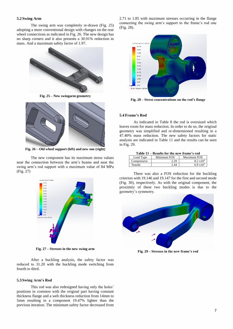
5.4 Frame’s Rod
As indicated in Table 8 the rod is oversized which
leaves room for mass reduction. In order to do so, the original
geometry was simplified and re-dimensioned resulting in a
47.40% mass reduction. The new safety factors for static
analysis are indicated in Table 11 and the results can be seen
in Fig. 29.
Table 11 – Results for the new frame’s rod
Load Type Minimum FOS Maximum FOS
Compressive 2.29 8.2 x10⁴
Tensile 2.44 6.9 x10³
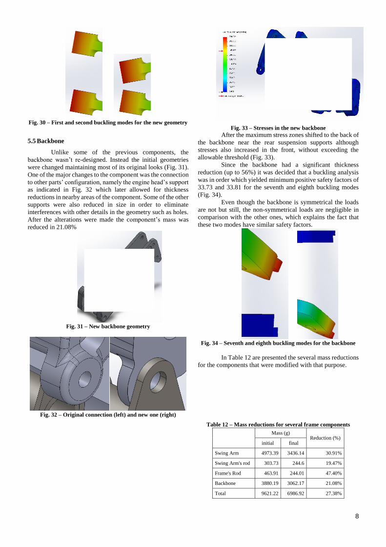
There was also a FOS reduction for the buckling
criterion with 19.146 and 19.147 for the first and second mode
(Fig. 30), respectively. As with the original component, the
proximity of these two buckling modes is due to the
geometry’s symmetry.
Fig. 29 – Stresses in the new frame’s rod
8
Fig. 30 – First and second buckling modes for the new geometry
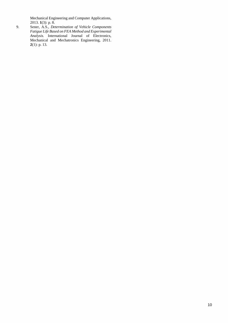
5.5 Backbone
Unlike some of the previous components, the
backbone wasn’t re-designed. Instead the initial geometries
were changed maintaining most of its original looks (Fig. 31).
One of the major changes to the component was the connection
to other parts’ configuration, namely the engine head’s support
as indicated in Fig. 32 which later allowed for thickness
reductions in nearby areas of the component. Some of the other
supports were also reduced in size in order to eliminate
interferences with other details in the geometry such as holes.
After the alterations were made the component’s mass was
reduced in 21.08%
Fig. 31 – New backbone geometry
Fig. 32 – Original connection (left) and new one (right)
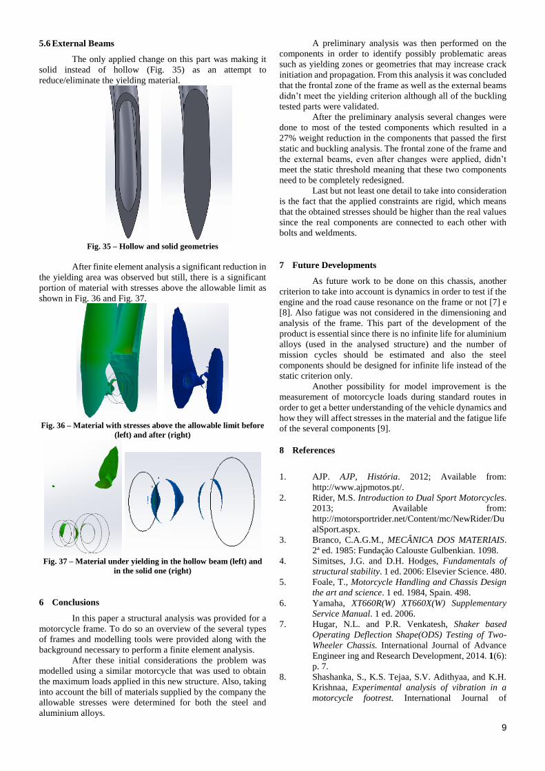
Fig. 33 – Stresses in the new backbone
After the maximum stress zones shifted to the back of
the backbone near the rear suspension supports although
stresses also increased in the front, without exceeding the
allowable threshold (Fig. 33).
Since the backbone had a significant thickness
reduction (up to 56%) it was decided that a buckling analysis
was in order which yielded minimum positive safety factors of
33.73 and 33.81 for the seventh and eighth buckling modes
(Fig. 34).
Even though the backbone is symmetrical the loads
are not but still, the non-symmetrical loads are negligible in
comparison with the other ones, which explains the fact that
these two modes have similar safety factors.
Fig. 34 – Seventh and eighth buckling modes for the backbone
In Table 12 are presented the several mass reductions
for the components that were modified with that purpose.
Table 12 – Mass reductions for several frame components
Mass (g)
Reduction (%) initial final
Swing Arm 4973.39 3436.14 30.91%
Swing Arm's rod 303.73 244.6 19.47%
Frame's Rod 463.91 244.01 47.40%
Backbone 3880.19 3062.17 21.08%
Total 9621.22 6986.92 27.38%
9
5.6 External Beams
The only applied change on this part was making it
solid instead of hollow (Fig. 35) as an attempt to
reduce/eliminate the yielding material.
Fig. 35 – Hollow and solid geometries
After finite element analysis a significant reduction in
the yielding area was observed but still, there is a significant
portion of material with stresses above the allowable limit as
shown in Fig. 36 and Fig. 37.
Fig. 36 – Material with stresses above the allowable limit before
(left) and after (right)
Fig. 37 – Material under yielding in the hollow beam (left) and
in the solid one (right)
6 Conclusions
In this paper a structural analysis was provided for a
motorcycle frame. To do so an overview of the several types
of frames and modelling tools were provided along with the
background necessary to perform a finite element analysis.
After these initial considerations the problem was
modelled using a similar motorcycle that was used to obtain
the maximum loads applied in this new structure. Also, taking
into account the bill of materials supplied by the company the
allowable stresses were determined for both the steel and
aluminium alloys.
A preliminary analysis was then performed on the
components in order to identify possibly problematic areas
such as yielding zones or geometries that may increase crack
initiation and propagation. From this analysis it was concluded
that the frontal zone of the frame as well as the external beams
didn’t meet the yielding criterion although all of the buckling
tested parts were validated.
After the preliminary analysis several changes were
done to most of the tested components which resulted in a
27% weight reduction in the components that passed the first
static and buckling analysis. The frontal zone of the frame and
the external beams, even after changes were applied, didn’t
meet the static threshold meaning that these two components
need to be completely redesigned.
Last but not least one detail to take into consideration
is the fact that the applied constraints are rigid, which means
that the obtained stresses should be higher than the real values
since the real components are connected to each other with
bolts and weldments.
7 Future Developments
As future work to be done on this chassis, another
criterion to take into account is dynamics in order to test if the
engine and the road cause resonance on the frame or not [7] e
[8]. Also fatigue was not considered in the dimensioning and
analysis of the frame. This part of the development of the
product is essential since there is no infinite life for aluminium
alloys (used in the analysed structure) and the number of
mission cycles should be estimated and also the steel
components should be designed for infinite life instead of the
static criterion only.
Another possibility for model improvement is the
measurement of motorcycle loads during standard routes in
order to get a better understanding of the vehicle dynamics and
how they will affect stresses in the material and the fatigue life
of the several components [9].
8 References
1. AJP. AJP, História. 2012; Available from:
http://www.ajpmotos.pt/.
2. Rider, M.S. Introduction to Dual Sport Motorcycles.
2013; Available from:
http://motorsportrider.net/Content/mc/NewRider/Du
alSport.aspx.
3. Branco, C.A.G.M., MECÂNICA DOS MATERIAIS.
2ª ed. 1985: Fundação Calouste Gulbenkian. 1098.
4. Simitses, J.G. and D.H. Hodges, Fundamentals of
structural stability. 1 ed. 2006: Elsevier Science. 480.
5. Foale, T., Motorcycle Handling and Chassis Design
the art and science. 1 ed. 1984, Spain. 498.
6. Yamaha, XT660R(W) XT660X(W) Supplementary
Service Manual. 1 ed. 2006.
7. Hugar, N.L. and P.R. Venkatesh, Shaker based
Operating Deflection Shape(ODS) Testing of Two-
Wheeler Chassis. International Journal of Advance
Engineer ing and Research Development, 2014. 1(6):
p. 7.
8. Shashanka, S., K.S. Tejaa, S.V. Adithyaa, and K.H.
Krishnaa, Experimental analysis of vibration in a
motorcycle footrest. International Journal of
10
Mechanical Engineering and Computer Applications,
2013. 1(3): p. 8.
9. Sener, A.S., Determination of Vehicle Components
Fatigue Life Based on FEA Method and Experimental
Analysis. International Journal of Electronics,
Mechanical and Mechatronics Engineering, 2011.
2(1): p. 13.


![Satellite Attitude Control Using Three Reaction Wheels · Satellite attitude control using three reaction wheels ... [12]. A reaction wheel is a device that applies torque ... The](https://img.pdfslide.net/doc/110x75/5b885d727f8b9abf5c8b699b/satellite-attitude-control-using-three-reaction-satellite-attitude-control-using.jpg)


![1 Nonlinear Analysis and Control of a Reaction Wheel-based ......and a learning algorithm enabling a successful jump-up.1 In [13] several design variants of a reaction wheel-based](https://img.pdfslide.net/doc/110x75/5fa20610ec95402ecc572d7e/1-nonlinear-analysis-and-control-of-a-reaction-wheel-based-and-a-learning.jpg)