Embed Size (px)
Citation preview

OWNER’S MANUAL P/N A5058-SNOS
MOTORCYCLE
Kit Numbers: 03001NOS, 03003NOS, 03008NOS, & 03011NOS NOTICE: Installation of Nitrous Oxide Systems Inc. products signifies that you have read this document and have
agreed to the terms stated within.
It is the purchaser’s responsibility to follow all installation instruction guidelines and safety procedures supplied with the product as it is received by the purchaser to determine the compatibility of the product with the vehicle or the device the purchaser intends to install the product on. Nitrous Oxide Systems Inc. assumes no responsibility for damages occurring from accident, misuse, abuse, improper installation, improper operation, lack of reasonable care, or all previously stated reasons resulting from incompatibility with other manufacturers’ products. Nitrous Oxide Systems Inc. assumes no responsibility or liability for damages incurred by the use of products manufactured or sold by Nitrous Oxide Systems Inc. on vehicles used for competition or racing. Nitrous Oxide Systems Inc. neither recommends nor condones the use of products manufactured or sold by Nitrous Oxide Systems Inc. on vehicles, which may be driven on public roads or highways, and assumes no responsibility for damages incurred by such use. NOS nitrous oxide is legal for use in most states when used in accordance with state and local traffic laws. NOS does not recommend or condone the use of its products in illegal racing activities. NOS has not pursued California Air Research Board (CARB) exemptions for its kits, hence, they are not legal for use on pollution-controlled vehicles in California. A correctly installed NOS nitrous system should not alter the emission control performance of your vehicle under standard EPA test cycle conditions.

2
HAZARDS DEFINED
This manual presents step-by-step instructions that describe the process of installing your NOS Nitrous Oxide Injection System. These procedures provide a framework for installation and operation of this kit. Parts are referenced by name and number to avoid confusion. Within the instructions, you are advised of potential hazards, pitfalls, and problems to avoid. The following examples explain the various hazard levels: WARNING! Failure to comply with instructions may result in injury or death. CAUTION! Failure to comply with instructions may result in damage to equipment.
NOTE: This information is important, needs to be emphasized, and is set apart from the rest of the text.
HINT: These special instructions provide a handy work tip.
NITROUS OXIDE INJECTION SYSTEM SAFETY TIPS
WARNINGS Do not attempt to start the engine if the nitrous has been injected while the engine was not running. Disconnect the coil wire and turn the engine over with the throttle wide open for several revolutions before attempting to start. Failure to do so can result in extreme engine damage. Never permit oil, grease, or any other readily combustible substances to come in contact with cylinders, valves, solenoids, hoses, and fittings. Oil and certain gases (such as oxygen and nitrous oxide) may combine to produce a highly flammable condition. Never interchange nitrous and fuel solenoids. Failure to follow these simple instructions can result in extreme engine damage and/or personal injury. Never drop or violently strike the bottle. Doing so may result in an explosive bottle failure. Never change pressure settings of the safety relief valve on the nitrous bottle valve. Increasing the safety relief valve pressure settings may create an explosive bottle hazard. Identify the gas content by the NOS label on the bottle before using. If the bottle is not identified to show the gas contained, return the bottle to the supplier. Do not deface or remove any markings, which are on the nitrous bottle. Nitrous bottle valves should always be closed when the system is not being used. Notify the supplier of any condition, which might have permitted any foreign matter to enter the valve or bottle. Keep the valves closed on all empty bottles to prevent accidental contamination. After storage, open the nitrous bottle valve for an instant to clear the opening of any possible dust or dirt. It is important that all threads on the valves and solenoids are properly mated. Never force connections that do not fit properly. CONGRATULATIONS on purchasing your NOS Nitrous Oxide Injection System. Your system is composed of the highest
quality components available. It should provide many miles of trouble-free performance when used correctly. If you have any questions regarding the performance of your system, call NOS Powersports Technical Service at 1-866-464-6553.

3
TABLE OF CONTENTS
WHAT IS NITROUS OXIDE? .......................................................................................................3 Do’s and Don’ts of Nitrous Oxide ..............................................................................................4 CHAPTER 1—INTRODUCTION TO YOUR NOS NITROUS OXIDE KIT ....................................4
1.1 General Information ..........................................................................................................4 1.2 System Requirements ......................................................................................................4 1.2 Kit Components ................................................................................................................5
CHAPTER 2 KIT INSTALLATION ..............................................................................................6 2.1 Bottle Mounting Instructions ...........................................................................................6 2.2 Bottle Orientation ..............................................................................................................6 2.3 Bottle Installation ..............................................................................................................8 2.4 Solenoid Mounting ............................................................................................................8
2.4.1 Nitrous Solenoid Installation ..........................................................................................9 2.4.2 Fuel Solenoid Installation ..............................................................................................9
2.5 Fogger Nozzle Installation ................................................................................................9 2.6 Solenoid/Fogger Nozzle Installation .............................................................................. 10 2.7 Nitrous Feed Line Mounting ........................................................................................... 11 2.8 Fuel Pump Installation .................................................................................................... 11 2.9 Electrical System Installation ........................................................................................ 11
2.9.1 Microswitch, Arming Switch, & Wiring - Grounding Horn Circuit .................................. 12 2.9.2 Microswitch, Arming Switch, and Wiring - +12V Horn Circuit ..................................... 13 2.9.3 Microswitch Arming Switch and Wiring ........................................................................ 15
CHAPTER 3 BASELINE TUNING SUGGESTIONS ................................................................. 17 CHAPTER 4 PREPARING FOR OPERATION ......................................................................... 18 CHAPTER 5 ADVANCED TUNING FOR MAXIMUM POWER ................................................. 18
5.1.A Determining Optimum Nitrous/Fuel Jetting .................................................................... 18 5.1.B Determining Optimum Ignition Timing ............................................................................ 19
CHAPTER 6 ROUTINE MAINTENANCE .................................................................................. 20 6.1 Nitrous Solenoid Filter .................................................................................................... 20 6.2 Nitrous Solenoid Plunger ............................................................................................... 20
6.2.1 General Information ..................................................................................................... 20 6.2.2 Nitrous Solenoid Plunger Disassembly and Inspection ............................................... 21
Appendix A Troubleshooting Guide ...................................................................................... 22 Nitrous Oxide Accessories ...................................................................................................... 23
WHAT IS NITROUS OXIDE?
NITROUS OXIDE… …Is a cryogenic gas composed of nitrogen and oxygen molecules …Is 36% oxygen by weight …Is non-flammable by itself …Is stored as a compressed liquid …Exists in two grades—U.S.P. and Nitrous Plus: U.S.P. is medical grade nitrous oxide; its common use is dental and veterinary anesthesia. It is also commonly used as a
propellant in canned whipped cream. U.S.P. is not available to the public. Nitrous Plus differs from U.S.P. in that it contains trace amounts of sulphur dioxide added to prevent substance abuse.
Nitrous Plus is intended for automotive applications and is available for sale to the public In motorcycle applications, Nitrous Plus and fuel are injected into the engine’s intake manifold, which produces the following results: Lowers engine intake air temperature, producing a dense inlet charge. Increases the oxygen content of the inlet charge (air is only 22 percent oxygen by weight). Increases the rate at which combustion occurs in the engine’s cylinders.

4
Do’s and Don’ts of Nitrous Oxide
Do’s Read all instructions before attempting to install your NOS nitrous system. Make sure your fuel delivery system is adequate for the nitrous jetting you have chosen. Inadequate fuel pressure or flow
will result in engine damage. Use 14 gauge (minimum) wire when installing electrical system components. Use high-quality connections at all electrical joints. Use PTFE-based paste on pipe style fittings.
Make sure your engine and related components (ignition, carburetor, and driveline) are in proper working condition. If nitrous is accidentally injected into the engine when it is not running, remove the engine coil wire, open the
throttle, and crank the engine 10 to 15 seconds before starting. Failure to do so can result in an explosive engine failure.
Use your NOS nitrous system only at wide-open throttle and at engine speeds above 2500 RPM. Install a proper engine to chassis ground. Failure to do so may result in an explosive failure of the main nitrous
supply line.
Use a high-quality fuel, as suggested in Chapter 3, Baseline Tuning Suggestions.
Don’ts Engage your nitrous system with the engine off. Severe engine damage can occur. Modify NOS nitrous systems (if you need a non-stock item, call NOS Technical Service for assistance; 1-866-464-6553) Overtighten AN type fittings. Use PTFE Tape on any pipe threads. Pieces of PTFE tape can break loose and become lodged in nitrous or fuel solenoids
or solenoid filters. Debris lodged in a nitrous or fuel solenoid can cause catastrophic engine failure.
Use sealant of any kind on AN fittings. Allow nitrous pressure to exceed 1100 psi. Excessive pressure can cause swelling or in extreme cases failure of the nitrous
solenoid plunger. Solenoid plungers are designed so that pressure-induced failures will prevent the valve from operating. No leakage should occur with this type of failure.
Inhale nitrous oxide. Death due to suffocation can occur. Allow nitrous oxide to come in contact with skin. Severe frostbite can occur. Use octane boosters that contain methanol. Fuel solenoid failure may occur, producing severe engine damage.
CHAPTER 1—INTRODUCTION TO YOUR NOS NITROUS OXIDE KIT
1.1 General Information
NOS nitrous oxide injection kits 03001NOS, 03003NOS, 03008NOS, and 03011NOS are designed for four-stroke motorcycles. Horsepower and torque increases due to these kits will vary with engine displacement and modifications. Approximate power increase estimates can be made based on massflow of nitrous oxide into the engine. The following table is provided to allow you to estimate the power increase you can expect for your application. WARNING! This NOS nitrous oxide injection kit can produce large increases in the torque and horsepower output of
your motorcycle or ATV. NOS strongly suggests that when installing your kit, you start with the smallest jets included in your kit. If you desire additional power, larger jets can then be installed. Operation of a high output system by an inexperienced rider can result in serious injury or death.
N2O/FUEL (JETTING)
APPROXIMATE POWER INCREASE PER NOZZLE
(1 NOZZLE PER CYLINDER)
APPROXIMATE N2O CONSUMPTION RATE
(PER NOZZLE)
16 / 18 9 BHP .1 lb./ 10 sec.
18 / 22 12 BHP .15 lb. / 10 sec.
20 / 24 15 BHP .18 lb./ 10 sec.
22 / 26 17 BHP .20 lb. / 10 sec.
1.2 System Requirements When used correctly, NOS nitrous oxide elevates cylinder pressures and makes temperatures while increasing combustion rate. These characteristics make the engine more sensitive to detonation. To ensure proper performance and engine life, the following tips are suggested:

5
Adequate fuel pressure and delivery – When designing your fuel system, plan on your pumps and lines flowing at least
0.10 gallons per hour per horsepower. The fuel pump included in this kit is capable of handling the fuel flow requirements of all suggested jetting combinations. High output engines will require the addition of a larger or separate fuel petcock.
Fuel Quality – Most motorcycle engines will perform satisfactorily on 92 octane pump gasoline when using nitrous oxide
injection. Higher output applications may require the use of 100+ octane racing fuel. Forged Pistons – On high horsepower applications, forged pistons are recommended. Cast pistons may be prone to
failure at elevated cylinder temperatures and pressures.
1.3 Kit Components Before beginning the installation of your NOS kit, compare the components you received with those shown in Figure 1 and Table 1, on the following two pages. If any components are missing, contact NOS PowersportsTech Service at 1-866-464-6553. Figure 1 Motorcycle System Kits 03001NOS, 03003NOS, 03008NOS, 03011NOS Parts List
NOTE: Parts may vary from actual parts in kit.

6
Table 1 Motorcycle System Kits 03001NOS, 03003NOS, 03008NOS, 03011NOS Parts List
ITEM DESCRIPTION QUANTITY PART #
1 Bottle Bracket 1 14100NOS
2 2 lb. Bottle 1 14710NOS
3 Nitrous Solenoid 1 18020NOS
4 Fuel Solenoid 1 18080NOS
5 N2O filter—4AN x 90° 1 15572NOS
6 Compression Fitting Adapter * *
7 Solenoid Bracket Assembly 2 16505NOS
8 Fuel Filter 1 15540NOS
9 Distribution Block * *
10 1/8” Male to 1/8” Male NPT Adapter+ * 17500NOS
11 1/8” Male to 1/8” Male NPT 90° Adapter * 17530NOS
12 Spray Nozzle Mounting Nut * 13715-SNOS
13 Spray Nozzle Mounting Collar * 13713-SNOS
14 Fogger Nozzle * 13700B-SNOS
15 1/8” Poly Line 1 *
16 B-Nut (Tube Nut) Blue * 17540NOS
17 1/8” Ferrule * 16404-SNOS
18 B-Nut (Tube Nut) Red * 17541NOS
19 Main N2O Feed Line (2ft.) 1 15250NOS
20 90° Swivel Adapter 4AN 1 17535NOS
21 Electric Fuel Pump 1 15760NOS
22 5/16” Brass Fuel Tee 1 15534NOS
23 5/16” to 1/4” Hose Barb 1 16251-SNOS
24 Fuel Hose Clamp 5 36R646A
25 Fuel Hose—Black (2ft.) 1 15000-SNOS
26 Waterproof Arming Switch 1 *
27 Relay * 15618NOS
28 Wiring Harness Relay** * 15604-SNOS
29 Pushbutton*** 1 15651NOS
30 Funnel Jet Assortment * *
31 Waterproof Microswitch 1 15640NOS
32 Microswitch Bracket 1 15644-SNOS
*Varies with application **Wiring, connectors, and inline fuse are also supplied.
***Included in kits 03100-03105NOS +Included in kits 03004NOS, 03005NOS, 03104NOS, & 03105NOS
CHAPTER 2 KIT INSTALLATION
2.1 Bottle Mounting Instructions Accurate calibration of your NOS nitrous system depends on the bottle remaining at a stable temperature. Mount the bottle away from heat sources such as the engine or exhaust system.
2.2 Bottle Orientation Bottle placement is critical to the performance of your NOS nitrous system. It is important to understand how the bottle valve and siphon tube are assembled to properly orient the bottle in your vehicle and insure that it picks up liquid nitrous while undergoing acceleration. All 1 lb. and larger NOS nitrous bottles are assembled, so that the bottom of the siphon tube is at the bottom of the bottle and opposite the bottle label (Figure 2). All 10 oz. bottles are sold WITHOUT siphon tubes and must be mounted with the valve towards the ground. WARNING! DO NOT attempt to remove the siphon tube without completely emptying the bottle of nitrous and pressure.
A bottle mounted upside-down must have the siphon tube removed before use (Figure 3C). Non-siphon bottles can be ordered from NOS (10oz. bottles are non-siphon equipped).
If the bottle must be mounted parallel to the axles of the vehicle (sideways), the valve handle and label must be angled at approximately 45° toward the front of the vehicle (Figure 3D). This orientation will position the siphon tube toward the rear of the bottle.

7
Figure 2 Nitrous Bottle Siphon Tube Orientation
Figure 3 Nitrous Bottle Mounting Orientation
NOTE: 10 oz. bottle is not siphon tube equipped (see illustration 3C). Whenever the bottle is mounted in a lay-down position, the valve handle must be toward the front of the vehicle with the label facing up (Figure 3A). If the bottle is mounted vertically, the valve handle and label must face toward the front of the vehicle (Figure 3B). This orientation will position the siphon tube at the back of the bottle, where the liquid N2O will be during acceleration.

8
Figure 4 Exploded View
The most efficient mounting is the lay-down position with the valve handle toward the front of the vehicle. This position allows the greatest amount of liquid to be used before the siphon tube begins to pick up gaseous nitrous oxide.
2.3 Bottle Installation After you have determined the location and orientation of the nitrous bottle, use the following procedure to install the bottle: NOTE: Numbers in parentheses ( ) refer to the parts list/assembly drawing numbers for the components.
1. Slip the bottle mounting bracket (1) onto the bottle (2). 2. Locate a convenient mounting area for the bottle assembly on the frame at least 6 inches from the exhaust system. Do not
attach the bottle to any suspension components. 3. Securely mount the bottle assembly to the frame. 4. Tighten the bracket clamps.
2.4 Solenoid Mounting
Use the following procedures to install the nitrous solenoid (3) and the fuel solenoid (4).
NOTE: Remember to use only PTFE paste on the pipe threads.
HINT: Placement of the solenoid is often limited by the lack of possible mounting locations in the engine compartment.
However, if possible, observe the following suggestions:
Keep the solenoids and lines away from exhaust components. Keep the solenoids mounted above the Fogger Nozzles. Place the solenoids near the Fogger Nozzles so that the lines will be as short as possible. Trial fit the solenoids with all lines attached to ensure a proper fit. An additional solenoid bracket has been supplied so that the solenoids can be mounted separately or together on one
bracket. Either method is acceptable. Solenoids may be mounted sideways or upside-down if necessary.

9
2.4.1 Nitrous Solenoid Installation
1. Clamp the nitrous solenoid (3) in a bench vise. 2. Install the nitrous filter fitting (5) in the inlet port of the nitrous solenoid. 3. Install the compression fittings adapter(s) (6) into the outlet port of nitrous solenoid or distribution block (9).
4. Remove the nitrous solenoid assembly from the vise. 5. Attach the solenoid mounting bracket (7) to the bottom of the nitrous solenoid. 6. Select desired mounting location for the nitrous solenoid. 7. Install the nitrous solenoid. If the solenoid mounting location is difficult to access, leave the solenoid loose so that the
solenoid inlet and outlet ports can be easily accessed.
2.4.2 Fuel Solenoid Installation 1. Clamp the fuel solenoid (4) in a bench vise. 2. Install the fuel filter fitting (8) in the inlet port of the fuel solenoid. 3. Install the compression fitting adapter(s) (6) into the outlet port of the solenoid or distribution block (9) (depending on the
style of the kit). 4. Remove the fuel solenoid assembly from the vise. 5. Attach the solenoid mounting bracket (7) to the bottom of the nitrous solenoid. 6. Select desired mounting location for the nitrous solenoid. 7. Install the fuel solenoid. If the mounting location is difficult to access, leave the solenoid loose so that the solenoid inlet and
outlet ports can be easily accessed.
2.5 Fogger Nozzle Installation 1. Determine the location of the intake manifold or air cleaner inlet duct where the Fogger Nozzle(s) are to be mounted.
Figure 5 is usually a good guide for most applications. For unique motorcycles such as Harley-Davidsons, nozzle placement will vary. Figure 6 shows the suggested nozzle placement for Harley Davidson installations.
HINT: If possible, it is a good idea to mount the Fogger Nozzle with the discharge end of the nozzle facing downward.
Occasionally, when nozzles are mounted with the discharge end up, fuel will seep down the nitrous passageway and contaminate the seal in the nitrous solenoid causing damage. This is rare, but can occur.
2. Remove the following: air cleaner(s), inlet ducting, carburetor(s), and inlet manifold(s). NOTE: The degree of disassembly necessary will vary depending upon where you decide to place the Fogger Nozzle(s).
3. Drill a 7/16” hole at each location where the Fogger Nozzle is to be located. HINT: If installing the Fogger Nozzle in metal intake runners, it is not necessary to use the supplied nozzle nut and collar.
Instead of a 7/16” hole, drill a 1/4” hole and tap directly with a 1/16” NPT tap. The Fogger Nozzle will then screw directly into the tapped hole.
4. Install a Nozzle Nut (12) and Nozzle Collar (13) in each 7/16” hole. HINT: It is suggested that the Nozzle Nut and Nozzle Collar be assembled using Loctite to prevent the fitting from vibrating
loose. 5. Note the discharge side of the Fogger Nozzle (14). Install a Fogger Nozzle in each Nozzle Nut and Collar with the
discharge side of the nozzle pointing toward the engine. 6. Reinstall the components removed in Step 2. Do not reinstall any components that restrict access to the Fogger Nozzles.

10
Figure 5 Standard Nozzle Location
Figure 6 Harley Davidson Nozzle Location
2.6 Solenoid/Fogger Nozzle Installation 1. Measure and cut a length of Poly line (15) to connect the Fogger Nozzle fuel port to the fuel solenoid. Measure and cut a
second length of Poly line to run from the Fogger Nozzle nitrous port to the nitrous solenoid. 2. Install the desired N2O and fuel jet in the Fogger Nozzle. Refer to Chapter 3 “Baseline Tuning” for jetting recommendations. 3. Slip a blue B-Nut (16) & ferrule (17) on the nitrous side Poly line. Place a red B-Nut (18) & ferrule on the fuel side Poly line. 4. Insert the Poly line into the Fogger Nozzle. Tighten the B-Nuts finger tight. Turn an additional 1.5 turns. NOTE: Overtightening the compression nut may cause the Poly line to fail.
5. Repeat Steps 1 through 4 for each additional Fogger Nozzle.

11
6. Route the Poly line from the fuel side of the Fogger Nozzle to the compression fitting in the fuel solenoid or distribution
block. 7. Route the Poly line from the nitrous side of the Fogger Nozzle to the compression fitting in the nitrous solenoid. Cut to
length. 8. Loosen the nut on the compression-fitting adapter. Insert the end of the Poly line into the compression fitting. 9. Holding the Poly line firmly in place (bottomed in the compression fitting), tighten the compression fitting. 10. Repeat Steps 6 through 9 for each compression fitting. 11. Tighten the solenoid and solenoid bracket securely.
2.7 Nitrous Feed Line Mounting 1. Determine the route for your main nitrous feed line (19) to follow. Ensure that the path is clear of exhaust system,
suspension, electrical lines and components, and tires. 2. Feed the nitrous line along the proposed route. 3. Secure the nitrous supply line using nylon tie-wraps. NOTE: Stainless steel covering the main feed line is very abrasive. Shield paint components to prevent them from contacting
the main feed line. 4. Attach the nitrous supply line to the bottle. NOTE: In some applications, it is helpful to use the 90° swivel adapter (20) to attach the nitrous supply line to the nitrous bottle.
WARNING: Nitrous Oxide is dangerous to humans if inhaled or if it comes into contact with the skin. Always point the nitrous
line opening away from people when purging the line.
2.8 Fuel Pump Installation 1. Pick a mounting location for the fuel pump (21). Locate the fuel pump away from heat. The pump should be as low as
possible in relation to the fuel tank. 2. Install the fuel pump. 3. If you decide not to use a dual outlet petcock (Pingel type), choose a location where the primary fuel line is to be tapped. 4. Cut the primary fuel line. 5. Splice the brass fuel line TEE (22) fitting in the primary fuel line. If the factory fuel line hose is smaller than the brass TEE
fitting, hose barb fittings (23) may be used to adapt the brass TEE to your fuel line. Install hose clamps (24) on all fuel line fittings and tighten.
6. Connect the brass TEE fitting to the inlet port of the fuel pump using the fuel hose (25) and hose clamps. 7. Connect the outlet of the fuel pump to the fuel filter inlet port using the fuel hose and fuel clamps.
2.9 Electrical System Installation Use procedure 2.9.1 and refer to Figure 7 for electrical system installation on kits 03001NOS, 03003NOS, 03008NOS, 03011NOS with the grounding horn circuit. Use procedure 2.9.2 and refer to Figure 8 for electrical system installation on kits 03001NOS, 03003NOS, 03008NOS, 03011NOS with the +12V horn circuit. IMPORTANT: The wiring hardware and instructions included with this kit are intended for motorcycles that activate their horn
through a grounding circuit. Some Harley Davidsons activate their horn via a +12V circuit. Before attempting to wire your NOS nitrous oxide kit, examine a wiring diagram of your motorcycle, or check the horn circuit with a volt-ohm meter.

12
2.9.1 Microswitch, Arming Switch, & Wiring (03001-03011NOS)—Grounding Horn Circuit This wiring scheme is designed to work in conjunction with the existing horn button on your motorcycle. When the system is installed, as described below, the horn will work normally with the NOS system switch in the unarmed (off) position. Flipping the switch to the armed (on) position deactivates the horn, starts the electric fuel pump, and when the horn is pushed, with the ignition on, WOT activates the nitrous system. For a detailed view of the wiring diagram used for these kits, refer to Figure 7. 1. Disconnect the battery. 2. Mount the arming switch (26) within easy reach of the driver. 3. Install the relay (27) and relay harness (28) with the orange wire connected to the inline fuse assembly. The relay needs to
be mounted near the battery to allow the orange relay wire to reach the (+) battery terminal. 4. Select the mounting location for the microswitch (31). The microswitch should be positioned so that it does not interfere
with the throttle linkage movement while allowing the switch to be triggered at WOT. Figures 10, 11, & 12 depict 3 typical mounting conditions. Figure 13 illustrates the operating principle of the microswitch/throttle linkage mechanism.
NOTE: Due to a wide variety of carburetor and throttle linkage combinations in use, it is impossible to supply a microswitch
bracket custom tailored to each application. The universal bracket supplied will need to be modified to fit your specific application using the steps 5-9.
CAUTION: Ensure that the microswitch/mounting bracket does not interfere with the operation of throttle linkage. A binding or
sticking throttle linkage can result in serious injury or death to operator or passengers. 5. Trace and cut out an outline of the microswitch from a piece of heavy construction paper or manila envelope paper. 6. Modify the template (trim, cut bend, etc.) to fit your carburetor and throttle linkage. 7. Trace the modified template outline onto the microswitch bracket (32). 8. Trim and bend the microswitch bracket to fit. 9. Install the microswitch and microswitch bracket. 10. Connect the red wire from the relay to one post on the microswitch. 11. Connect the open post of the microswitch to the lower right terminal on the arming switch using the red wire. 12. Connect the fuel pump positive (+) pole to the lower right terminal on the arming switch. 13. Connect one wire from each solenoid together. Join the solenoid wires to the blue relay wire. See diagram. NOTE: Solenoids are non-polarized; either wire will do.
14. Splice the remaining lead from each solenoid together. Then, connect to the good ground on the frame. 15. Connect the green relay wire to the lower left terminal on the arming switch.

13
Figure 7 4-Stroke Wiring Schematic for Kits 03001NOS, 03003NOS, 03008NOS, 03011NOS
NOTE: The wiring orientation on the wiring switch is noted on Figure 7.
16. Connect the fuel pump negative (-) pole to the good ground on the frame. 17. Locate the grounding wire between the horn and the button. Cut the wire at a convenient location. Connect the cut wire
from the horn to the upper left terminal of the arming switch. 18. Connect the cut wire form the horn button to the center terminal on the left side of the arming switch. 19. Connect the middle right terminal on the arming switch to a switched 12V source, through a 15 amp fuse. 20. Reconnect the battery. 21. Reinstall any items (air cleaner, inlet ducts, etc;) not yet replaced.
2.9.2 Microswitch, Arming Switch, and Wiring (03001-03011)— +12V Horn Circuit This wiring scheme is designed to work in conjunction with the existing horn button on your motorcycle. When the system is installed, as described below, the horn will work normally with the NOS system switch in the unarmed (off) position. Flipping the switch to the armed (on) position deactivates the horn, starts the electric fuel pump, and when the horn button is pushed with the ignition on, WOT activates the nitrous system. For a detailed view of the wiring diagram used for these kits, refer to Figure 8. 1. Disconnect the battery. 2. Mount the arming switch (26) within easy reach of the driver. 3. Install the relay (27) and relay harness (28) with the orange wire connected to the inline fuse assembly. The relay needs to
be mounted near the battery to allow the orange relay wire to reach the (+) battery terminal. 4. Select the mounting location for the microswitch (31). The microswitch should be positioned, so that it does not interfere
with the throttle linkage movement while allowing the switch to be triggered at WOT. Figures 10, 11, & 12 depict 3 typical mounting conditions. Figure 13 illustrates the operating principle of the microswitch/throttle linkage mechanism.
NOTE: Due to a wide variety of carburetor and throttle linkage combinations in use, it is impossible to supply a microswitch
bracket custom tailored to each application. The universal bracket supplied will need to be modified to fit your specific application using the steps 5-9.

14
CAUTION: Ensure that the microswitch/mounting bracket does not interfere with the operation of throttle linkage. A binding or
sticking throttle linkage can result in serious injury or death to operator or passengers. 5. Trace and cut out an outline of the microswitch from a piece of heavy construction paper or manila envelope paper. 6. Modify the template (trim, cut bend, etc;) to fit your carburetor and throttle linkage. 7. Trace the modified template outline onto the microswitch bracket (32). 8. Trim and bend the microswitch bracket to fit. 9. Install the microswitch and microswitch bracket. 10. Connect the green wire from the relay to one post on the microswitch. 11. Connect the open post of the microswitch to a good ground on the frame. 12. Connect the fuel pump positive (+) pole to the lower right terminal on the arming switch. 13. Connect one wire from each solenoid together. Join the solenoid wires to the blue relay wire. See diagram. NOTE: Solenoids are non-polarized, either wire will do.
14. Splice the remaining lead from each solenoid together. Then, connect to the good ground on the frame. 15. Connect the red relay wire to the lower left terminal on the arming switch. NOTE: The wiring orientation on the wiring switch is noted on Figure 8.
16. Connect the fuel pump negative (-) pole to the good ground on the frame. 17. Locate the power wire between the horn and the button. Cut the wire at a convenient location. Connect the cut wire from
the horn to the upper left terminal of the arming switch. 18. Connect the cut wire form the horn button to the center terminal on the left side of the arming switch. 19. Connect the middle right terminal on the arming switch to a switched 12V source, through a 15 amp fuse. 20. Reconnect the battery. 21. Reinstall any items (air cleaner, inlet ducts, etc;) not yet replaced.
Figure 8 4-Stroke +12V Horn Wiring Schematic for Kits 03001NOS, 03003NOS, 03008NOS, 03011NOS

15
2.9.3 Microswitch Arming Switch and Wiring REMEMBER: On vehicles with minimal or non-existent charging systems, it will be necessary to add a small 12 volt battery
capable of producing at least 12 amps. For a detailed view of the wiring diagram used for these kits, refer to Figure 9.
Figure 9 Additional Wiring Options
Figure 10 Typical Mounting Location for Microswitch

16
Figure 11 Typical Mounting Location for Microswitch
Figure 12 Typical Mounting Location for Microswitch
Figure 13 Operating Principle of the Microswitch/Throttle Linkage Mechanism

17
1. Mount the battery. 2. Install the activation button (29) and the arming switch (28) within easy reach of the driver. 3. Install the relay (27) and the relay harness (28) with the orange wire connected to the inline fuse assembly. The relay
needs to be mounted near the battery to allow the orange relay wire to reach the (+) battery terminal. 4. Select the mounting location for the microswitch (31). The microswitch should be positioned so that it does not interfere
with the throttle linkage movement, while allowing the switch to be triggered at WOT. Figures 10, 11, & 12 depict 3 typical mounting conditions. Figure 13 illustrates the operating principle of the microswitch/throttle linkage mechanism.
NOTE: Due to the wide variety of carburetor and throttle linkage combinations in use, it is impossible to supply a microswitch
bracket custom tailored to each vehicle. The universal bracket supplied will need to be modified to fit your specific application using steps 5-9.
CAUTION! Ensure that the microswitch/mounting bracket does not interfere with the operation of the throttle linkage. A binding
or sticking throttle linkage can result in serious injury or death to the operator and passengers. 5. Trace and cut out an outline of the microswitch from a piece of heavy construction paper or manila envelope paper. 6. Modify the template (trim, cut, bend, etc;) to fit your carburetor and throttle linkage. 7. Trace the modified template outline onto the microswitch bracket (32). 8. Trim and bend the microswitch bracket to fit. 9. Install the microswitch and microswitch bracket. 10. Connect the red wire from the relay to one post on the microswitch. 11. Connect the open post of the microswitch to one wire on the pushbutton. 12. Connect one wire from each solenoid together. Join the solenoid wires to the blue relay wire. NOTE: Solenoids are non-polarized, either wire will do.
13. Splice the remaining leads from the solenoids together. Then connect to a good ground connection on the frame. 14. Connect the green relay wire to a good ground connection on the frame. 15. Connect the open wire from the activation pushbutton to the lower terminal on the arming switch. NOTE: The wiring orientation on the wiring switch is noted in Figure 9.
16. Connect the fuel pump positive (+) pole to the terminal on the battery. 17. Connect the fuel pump negative (-) pole to a good ground connection on the frame. 18. Connect the upper terminal on the arming switch to one lead of fuse assembly. 19. Connect the orange lead from the relay to the positive (+) terminal on the battery. 20. Reconnect the negative (-) terminal of the battery. 21. Reinstall any items (air cleaner, inlet ducts etc;) not yet replaced.
CHAPTER 3 BASELINE TUNING SUGGESTIONS Your NOS nitrous oxide injection kit 03001NOS, 03003NOS, 03008NOS, 03011NOS can be easily adjusted to vary engine output. Listed below are the tuning recommendations necessary for proper performance while retaining suitable engine reliability. NOTE: The jetting combinations listed below are conservative, based upon 900 psi nitrous oxide bottle pressure and 4 to 5 psi
flowing fuel pressure. Operating with these pressure levels should yield safe and reliable power increases.

18
Table 2 Recommended Tuning Combinations for NOS nitrous injection kits
Jet
Pack N2O/Fuel Jetting
Fuel Quality Applicable NOS Kit #
A 16/18** 92+ octane pump gas All***
B 18/22** 92+ octane pump gas 03002NOS*, 03003NOS, 03004NOS*, 03005NOS*, 03007NOS*, 03008NOS*, 03011NOS, 03021NOS*, 03102NOS*, 03103NOS*, 03104NOS* & 03105NOS*
C 20/24 92+ octane pump gas 03003NOS, 03005NOS*, 03008NOS*, 03011NOS,
03021NOS*, & 03105NOS*
D 22/26 92+ octane pump gas 03011NOS & 03021NOS*
*These items are now obsolete.
**On smaller displacement engines, these jetting combinations may be too rich. Call the NOS technical department for jetting suggestions.
***Not recommended for engines smaller than 100cc. Call NOS for jetting combinations for special applications.
CHAPTER 4 PREPARING FOR OPERATION After you have completed the installation of your NOS kit, perform the following checkout procedure before operating your vehicle. NOTE: Before performing steps 1-4, make sure that the nitrous bottle valve is closed and the main nitrous supply line is empty.
1. Turn on the fuel pump. 2. Check all the fuel lines and fittings for leaks. 3. Start the engine. 4. Turn the arming toggle switch on. Set the engine speed at 2000 RPM. Briefly depress the activation arm on the
microswitch. The engine speed should decrease, if the fuel delivery system is performing properly. If not, refer to Appendix A, Troubleshooting Guide.
5. Open the nitrous bottle valve. NOTE: There should be no change in the engine idle speed. If the idle speed changes, refer to Appendix A, Troubleshooting
Guide. 6. Inspect the nitrous lines and fittings for leaks. 7. ENJOY!!
CHAPTER 5 ADVANCED TUNING FOR MAXIMUM POWER After performing the Baseline Tuning Suggestions—Chapter 3, if you desire to maximize the performance of your system, perform the following: NOTE: Always perform the nitrous/fuel jetting modifications listed in Section 5.1.A before attempting to optimize the ignition
timing (Section 5.1.B). Improper nitrous/fuel jetting combinations can mislead you when attempting to optimize the ignition timing.
5.1.A Determining Optimum Nitrous/Fuel Jetting The jetting combinations included in your kit are compromises, intended to provide you with a safe starting point. They are intended to be used with 900 psi nitrous bottle pressure and 4-5 psi flowing fuel pressure. In many instances, installing slightly smaller fuel jets than the units provided in your kit will provide a more optimum nitrous/fuel ratio and increase power. Always run the baseline jetting included in your kit before attempting to decrease the fuel jet size. Optimum jetting can be determined using the following scheme.

19
1. Stabilize the nitrous bottle pressure at 900 psi. 2. Perform a dynamometer pull or full throttle pass down the racetrack. Note the power reading or vehicle mph (not e.t.).
Examine the spark plugs for the indication of lean or rich nitrous/fuel conditions (refer to Figure 14 for tips on reading spark plugs).
2A. If the spark plugs appear to be excessively rich, decrease the fuel jet size 2 steps (ex. 28 to 26, 26 to 24, etc;). 2B. If spark plugs appear to be excessively lean, increase the fuel jet size 2 steps. 2C. If spark plugs have a “like new” appearance on the porcelain and electrode, do not make a fuel jetting change.
3. Repeat steps 1 and 2, until the desired mixture is obtained.
Figure 14 Spark Plug Condition
How to Read Spark Plugs form a Nitrous Oxide Injected Engine
A. Correct Timing, Mixture, and Spark Plug Heat Range
Ground strap retains a “like new” appearance. Edges are crisp, with no signs of discoloration. Porcelain retains c lear white to a light tan color appearance with no “peppering” or spotting.
B. Excessively Rich Mixture
Porcelain may be fuel stained, appearing brown or black. In extreme cases, ground strap, electrode, and porcelain may be damp with gasoline, or smell of fuel.
C. Detonation
Edges of the ground strap may become rounded. Porcelain has the appearance of being sprinkled with pepper, or may have aluminum speckles. During heavy detonation, the ground strap tip may burn off. This phenomena can result from excessive ignition timing, too high a heat range spark plug, or inadequate fuel octane.
D. Excessively Lean Mixture
Edges of the ground strap may become rounded. Under moderate overheating, the tip of the ground strap can discolor, usually turning purple, or the entire ground strap can become discolored.
5.1.B Determining Optimum Ignition Timing IMPORTANT! Ignition timing should be retarded approximately 2 degrees per 50 HP increase due to nitrous oxide injection.
Start with the engine’s best total timing and reduce from there. Use the initial settings, which are 2-3 degrees more retarded than you expect to be optimum.
Example: Ignition Timing with Nitrous----------------------------- 38°
100 HP Increase from Nitrous-------------------------- 4° Retard Initial Safety Margin--------------------------------------- 2° Retard Initial Timing with Nitrous-------------------------------- 32° The following scheme for determining ignition timing should allow you to determine the optimum setting for your vehicle, without incurring engine damage during the tuning phase. 1. Estimate the reduced ignition timing that you think will produce the best power, based upon the 2 degree retard per 25
horsepower increase rule. 2. Set the ignition timing 2 to 3 degrees retarded from your best power estimate setting. 3. Stabilize the nitrous bottle pressure at 900 psi. 4. Perform a dynamometer pull or a full throttle pass down the racetrack. Note the power reading or vehicle mph.

20
5. Increase the ignition timing 2 degrees. 6. Perform a dynamometer pull or a full throttle pass down the racetrack. Note the power reading or vehicle mph. Examine
the spark plugs for signs of detonation (refer to Figure 13 for tips on reading spark plugs).
6A. If power increase or vehicle mph increase and spark plugs show no sign of overheating or detonation, increase the
ignition timing 2 degrees. 6B. If power increase or vehicle mph increase and spark plugs begin to show slight signs of detonation—STOP. Do not
advance the timing further. You may choose to reduce the timing 2 degrees at this point for an extra margin of safety. 6C. If power decreases or vehicle mph decreases, reduce the ignition timing 2 degrees.
7. Repeat step 6 until optimum ignition timing is obtained.
CHAPTER 6 ROUTINE MAINTENANCE
6.1 Nitrous Solenoid Filter
When nitrous bottles are refilled they can become contaminated with debris, if the refiller does not have an adequate filter in his transfer pump mechanism. Contaminants in the bottle will eventually become lodged in the nitrous solenoid filter fitting. You should periodically (after every 20-30 pounds of nitrous usage) examine the mesh in the nitrous filter for debris. To clean the filter, follow the following steps: 1. Close the valve on the nitrous bottle. 2. Empty the main nitrous feed line. 3. Disconnect the main nitrous feed line from the nitrous solenoid. 4. Remove the nitrous filter fitting from the nitrous solenoid. 5. Remove all PTFE paste debris from the solenoid inlet port threads and from the nitrous solenoid filter pipe threads. 6. Examine the mesh in the nitrous filter fitting for contaminants. Blow out debris with compressed air is necessary. 7. Apply fresh PTFE paste to the nitrous filter pipe threads. Reinstall the filter in the nitrous solenoid. 8. Reconnect the main nitrous supply line to the nitrous solenoid.
6.2 Nitrous Solenoid Plunger
6.2.1 General Information The seals used in NOS nitrous solenoid plungers are constructed from materials, which are designed to be used with nitrous oxide. When kept free from fuel contaminants or from overpressurization, they should provide trouble free performance. You should periodically (after every 20-30 pounds of nitrous usage) examine the seal in the nitrous solenoid plunger. If the fogger nozzles are mounted downstream of the carburetor butterflies, the nitrous solenoid plunger will get exposed to fuel vapors. This is unavoidable. Fluctuations in the intake manifold pressure, due to opening and closing of the throttle, induce flow into and out of the NOS Fogger nozzles, when the NOS system is not in use. Long term exposure of the nitrous solenoid plunger seal to fuel vapors will result in the swelling of the plunger seal. This will reduce nitrous flow (causing an excessively rich nitrous/fuel condition and a loss of power). The seals used in NOS nitrous solenoid plunger are designed to work at pressures up to 1100 psi. Exposing the plunger to excessive pressure (whether the vehicle is sitting or in-use) can result in the plunger swelling or in extreme cases disintegrating. NOTE: The seals are designed so that if they fail due to overpressurization, they will not leak, the valve will just fail to flow
nitrous oxide. Swelling of the nitrous solenoid plunger seal will reduce nitrous flow (causing an excessively rich nitrous/fuel condition and a loss of power).
21
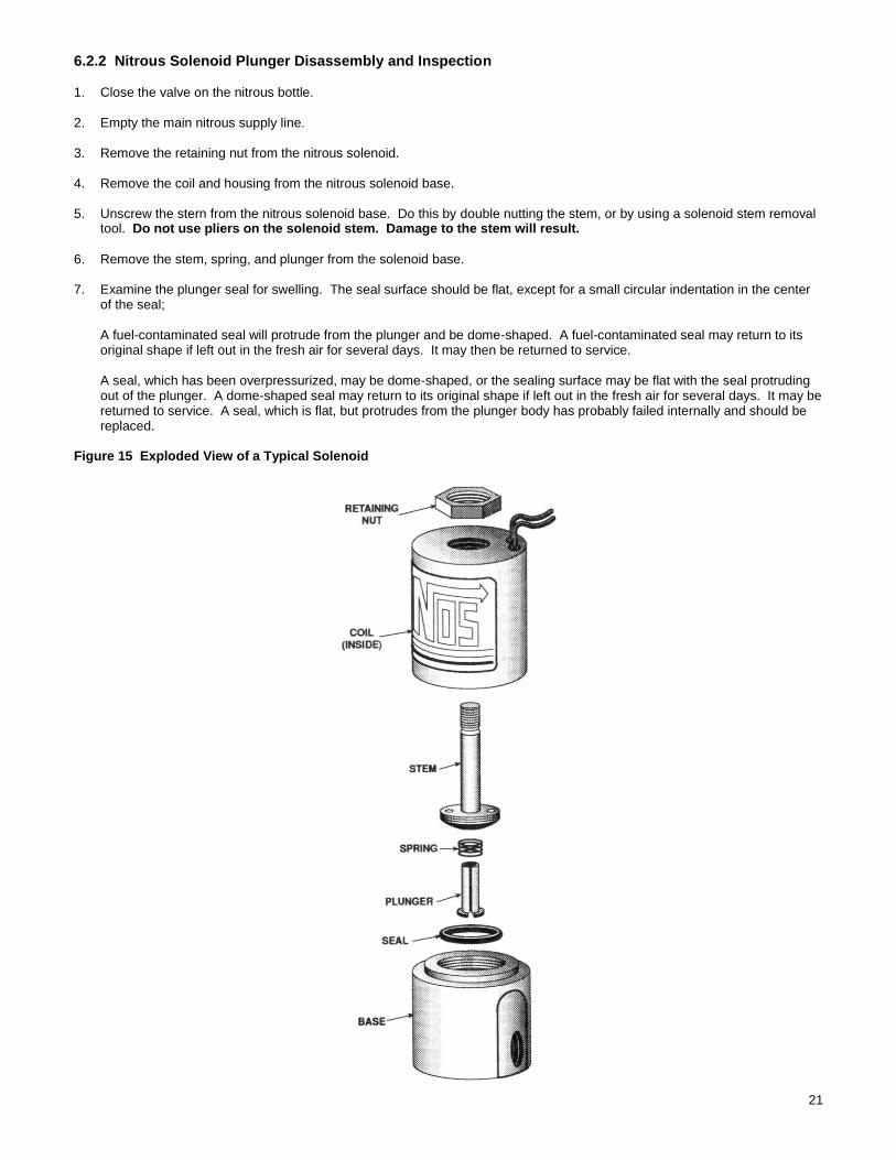
6.2.2 Nitrous Solenoid Plunger Disassembly and Inspection 1. Close the valve on the nitrous bottle. 2. Empty the main nitrous supply line. 3. Remove the retaining nut from the nitrous solenoid. 4. Remove the coil and housing from the nitrous solenoid base. 5. Unscrew the stern from the nitrous solenoid base. Do this by double nutting the stem, or by using a solenoid stem removal
tool. Do not use pliers on the solenoid stem. Damage to the stem will result.
6. Remove the stem, spring, and plunger from the solenoid base. 7. Examine the plunger seal for swelling. The seal surface should be flat, except for a small circular indentation in the center
of the seal;
A fuel-contaminated seal will protrude from the plunger and be dome-shaped. A fuel-contaminated seal may return to its original shape if left out in the fresh air for several days. It may then be returned to service.
A seal, which has been overpressurized, may be dome-shaped, or the sealing surface may be flat with the seal protruding out of the plunger. A dome-shaped seal may return to its original shape if left out in the fresh air for several days. It may be returned to service. A seal, which is flat, but protrudes from the plunger body has probably failed internally and should be replaced.
Figure 15 Exploded View of a Typical Solenoid

22
Appendix A Troubleshooting Guide The troubleshooting chart on the following pages should help determine and rectify most problems with your installed NOS system. If you still need assistance determining or fixing problems, call NOS Motorsports at 1-866-464-6553.
PROBLEM POSSIBLE CAUSES DIAGNOSTIC PROCEDURE CORRECTIVE ACTION
No change in the engine speed when the fuel solenoid is activated (Preparing for Operation—Chapter 4).
System is wired incorrectly. Compare wiring to schematic. Wire per instructions
Restricted fuel line. Inspect fuel line for restrictions (crimped or plugged).
Remove restrictions.
Malfunctioning fuel solenoid. Turn arming switch ON. Activate microswitch. Solenoid should make “clicking” noise.
Repair/replace solenoid.
Fuel pump mounting Check to see that the pump is mounted below fuel level.
Reposition the pump below fuel level.
Change in the engine speed when the nitrous bottle valve is opened
Malfunctioning nitrous solenoid.
Remove and inspect the solenoid. Repair/replace solenoid.
Engine runs rich when system is activated.
Bottle valve not fully opened. Check bottle valve. Open valve fully.
Bottle mounted improperly. Check bottle orientation. Mount bottle properly.
Plugged nitrous filter. Inspect filter. Clean/replace filter.
Low bottle pressure. Check bottle temperature. Set bottle temperature to 75° to 85°F.
Inadequate nitrous supply. Weigh bottle. Fill bottle. 1-800-99-REFILL
Mismatched N2O/fuel jetting. Compare jetting to recommended values.
Install correct jets.
Excessive fuel pressure. Install fuel pressure gauge, such as NOS P/N 15900-SNOS in the fuel line. Measure the fuel pressure during acceleration, with the system activated.
Regulate pressure down, or install smaller fuel jetting.
Loose nitrous solenoid wiring.
Inspect the solenoid wiring. Repair wiring.
Malfunctioning nitrous solenoid.
Close the bottle valve. Disconnect nitrous solenoid outlet port. Disconnect solenoid (+) lead. Open nitrous bottle valve. Briefly connect +12V to solenoid. Solenoid should discharge N2O at high rate.
Rebuild solenoid.
No change in performance when system is activated.
System wired incorrectly. Compare nitrous wiring to schematic (Figures 7, 8, or 9).
Wire system per instructions.
Loose ground wire(s). Connect 12V test light to battery (+) terminal. Check for continuity at grounds noted in wiring schematic (Figures 7, 8, or 9).
Tighten/repair loose grounds.
No power to arming switch. Connect 12V test light to battery (-). Check for power at pole #1 on the arming switch.
Replace arming switch.
Malfunctioning pushbutton (horn button).
Turn bottle valve OFF. Turn arming switch ON. Connect 12V test light to battery (-). Turn pushbutton (horn button) switch ON. Check for continuity at pushbutton (horn button) output pole.
Replace pushbutton (horn button).
Overly rich fuel condition. Check for black smoke or backfiring through exhaust with system activated.
Install smaller fuel jet or decrease fuel pressure.
Partially clogged or plugged N2O filter.
Inspect N2O filter. Clean/replace N2O filter.
Engine detonates mildly when system is activated.
Excessive ignition timing. Check ignition timing. Reduce timing in 2° increments, up to 8° from non-nitrous conditions.
Inadequate octane fuel. Use higher octane fuel; up to 116VPC-16.

23
Spark plug heat range too high.
Reduce spark plug heat range (maximum two steps).
Too much nitrous flow. Reduce nitrous jetting.
Engine detonates heavily when system is activated.
Inadequate fuel delivery due to: Plugged fuel filter
Inspect fuel filter. Clean or replace filter.
Crimped fuel line. Inspect fuel line. Replace crimped line.
Weak fuel pump. Install fuel pressure gauge, such as NOS P/N 15900-SNOS in the fuel line. Run engine under load at WOT, with system activated. Fuel pressure should be at least 5 psi.
Alter fuel pump or replace, if necessary.
High RPM misfire when system is activated.
Excessive spark plug gap. Inspect spark plugs. Set spark plug gap at 0.030 to 0.035 inches.
Weak ignition/ignition component failure.
Inspect components (plug wires, magneto, etc.)
Replace worn components.
Surges under acceleration when system is activated.
Inadequate supply of nitrous.
Check bottle weight. Replace with full bottle.
Bottle mounted incorrectly. Compare bottle position and orientation to instructions.
Mount or orient bottle correctly.
Nitrous Oxide Accessories Nitrous and Fuel Pressure Gauges, P/N 15900-SNOS & 15910NOS, allow you to monitor nitrous and fuel pressure to maximize performance, while making sure that your system is operating properly.

24
NOS Technical Support 1801 Russellville Road
Bowling Green, KY 42101-3542
Phone: 1-866-464-6553
For online help, please refer to the Tech Service section of our website: www.holley.com
A5058-SNOS Revision Date: 12-29-15