Embed Size (px)
Citation preview

Ninja ZX-6R
MotorcycleService Manual

This quick reference guide will assistyou in locating a desired topic or pro-cedure.•Bend the pages back to match theblack tab of the desired chapter num-ber with the black tab on the edge ateach table of contents page.•Refer to the sectional table of contentsfor the exact pages to locate the spe-cific topic required.
Quick Reference Guide
General Information 1 jFuel System 2 jCooling System 3 jEngine Top End 4 jClutch 5 jEngine Lubrication System 6 jEngine Removal/Installation 7 jCrankshaft/Transmission 8 jWheels/Tires 9 jFinal Drive 10 jBrakes 11 jSuspension 12 jSteering 13 jFrame 14 jElectrical System 15 jAppendix 16 j

Ninja ZX-6R
MotorcycleService Manual
All rights reserved. No parts of this publication may be reproduced, stored in a retrieval system, ortransmitted in any form or by any means, electronic mechanical photocopying, recording or otherwise,without the prior written permission of Quality Assurance Division/Consumer Products & MachineryGroup/Kawasaki Heavy Industries, Ltd., Japan.No liability can be accepted for any inaccuracies or omissions in this publication, although every possible
care has been taken to make it as complete and accurate as possible.The right is reserved to make changes at any time without prior notice and without incurring an obligation
to make such changes to products manufactured previously. See your Motorcycle dealer for the latestinformation on product improvements incorporated after this publication.All information contained in this publication is based on the latest product information available at the time
of publication. Illustrations and photographs in this publication are intended for reference use only and maynot depict actual model component parts.
© 1999 Kawasaki Heavy Industries, Ltd. 7th Edition (1):Jun. 26, 2007 (K)
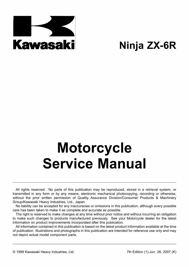
LIST OF ABBREVIATIONSA ampere(s) lb pound(s)ABDC after bottom dead center m meter(s)AC alternating current min minute(s)ATDC after top dead center N newton(s)BBDC before bottom dead center Pa pascal(s)BDC bottom dead center PS horsepowerBTDC before top dead center psi pound(s) per square inch°C degree(s) Celsius r revolutionDC direct current rpm revolution(s) per minuteF farad(s) TDC top dead center°F degree(s) Fahrenheit TIR total indicator readingft foot, feet V volt(s)g gram(s) W watt(s)h hour(s) Ω ohm(s)L liter(s)
Read OWNER’S MANUAL before operating.
EMISSION CONTROL INFORMATION
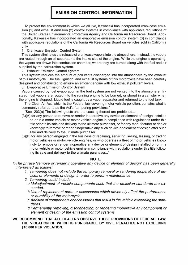
To protect the environment in which we all live, Kawasaki has incorporated crankcase emis-sion (1) and exhaust emission (2) control systems in compliance with applicable regulations ofthe United States Environmental Protection Agency and California Air Resources Board. Addi-tionally, Kawasaki has incorporated an evaporative emission control system (3) in compliancewith applicable regulations of the California Air Resources Board on vehicles sold in Californiaonly.1. Crankcase Emission Control SystemThis system eliminates the release of crankcase vapors into the atmosphere. Instead, the vapors
are routed through an oil separator to the intake side of the engine. While the engine is operating,the vapors are drawn into combustion chamber, where they are burned along with the fuel and airsupplied by the carburetion system.2. Exhaust Emission Control SystemThis system reduces the amount of pollutants discharged into the atmosphere by the exhaust
of this motorcycle. The fuel, ignition, and exhaust systems of this motorcycle have been carefullydesigned and constructed to ensure an efficient engine with low exhaust pollutant levels.3. Evaporative Emission Control SystemVapors caused by fuel evaporation in the fuel system are not vented into the atmosphere. In-
stead, fuel vapors are routed into the running engine to be burned, or stored in a canister whenthe engine is stopped. Liquid fuel is caught by a vapor separator and returned to the fuel tank.
The Clean Air Act, which is the Federal law covering motor vehicle pollution, contains what iscommonly referred to as the Act’s “tampering provisions.”“Sec. 203(a) The following acts and the causing thereof are prohibited...
(3)(A) for any person to remove or render inoperative any device or element of design installedon or in a motor vehicle or motor vehicle engine in compliance with regulations under thistitle prior to its sale and delivery to the ultimate purchaser, or for any manufacturer or dealerknowingly to remove or render inoperative any such device or element of design after suchsale and delivery to the ultimate purchaser.
(3)(B) for any person engaged in the business of repairing, servicing, selling, leasing, or tradingmotor vehicles or motor vehicle engines, or who operates a fleet of motor vehicles know-ingly to remove or render inoperative any device or element of design installed on or in amotor vehicle or motor vehicle engine in compliance with regulations under this title follow-ing its sale and delivery to the ultimate purchaser...”
NOTEThe phrase “remove or render inoperative any device or element of design” has been generallyinterpreted as follows:
1. Tampering does not include the temporary removal or rendering inoperative of de-vices or elements of design in order to perform maintenance.
2. Tampering could include:a.Maladjustment of vehicle components such that the emission standards are ex-ceeded.
b.Use of replacement parts or accessories which adversely affect the performanceor durability of the motorcycle.
c.Addition of components or accessories that result in the vehicle exceeding the stan-dards.
d.Permanently removing, disconnecting, or rendering inoperative any component orelement of design of the emission control systems.
WE RECOMMEND THAT ALL DEALERS OBSERVE THESE PROVISIONS OF FEDERAL LAW,THE VIOLATION OF WHICH IS PUNISHABLE BY CIVIL PENALTIES NOT EXCEEDING$10,000 PER VIOLATION.

TAMPERING WITH NOISE CONTROL SYSTEM PROHIBITED
Federal law prohibits the following acts or the causing thereof: (1) The removal or renderinginoperative by any person other than for purposes of maintenance, repair, or replacement, of anydevice or element of design incorporated into any new vehicle for the purpose of noise controlprior to its sale or delivery to the ultimate purchaser or while it is in use, or (2) the use of thevehicle after such device or element of design has been removed or rendered inoperative byany person.Among those acts presumed to constitute tampering are the acts listed below:•Replacement of the original exhaust system or muffler with a component not in compliancewith Federal regulations.• Removal of the muffler(s) or any internal portion of the muffler(s).• Removal of the air box or air box cover.•Modifications to the muffler(s) or air intake system by cutting, drilling, or other means if suchmodifications result in increased noise levels.
Foreword
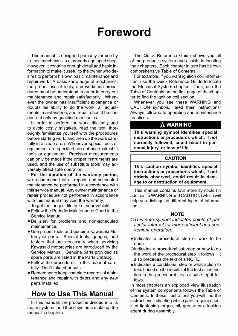
This manual is designed primarily for use bytrained mechanics in a properly equipped shop.However, it contains enough detail and basic in-formation to make it useful to the owner who de-sires to perform his own basic maintenance andrepair work. A basic knowledge of mechanics,the proper use of tools, and workshop proce-dures must be understood in order to carry outmaintenance and repair satisfactorily. When-ever the owner has insufficient experience ordoubts his ability to do the work, all adjust-ments, maintenance, and repair should be car-ried out only by qualified mechanics.In order to perform the work efficiently and
to avoid costly mistakes, read the text, thor-oughly familiarize yourself with the proceduresbefore starting work, and then do the work care-fully in a clean area. Whenever special tools orequipment are specified, do not use makeshifttools or equipment. Precision measurementscan only be made if the proper instruments areused, and the use of substitute tools may ad-versely affect safe operation.For the duration of the warranty period,
we recommend that all repairs and scheduledmaintenance be performed in accordance withthis service manual. Any owner maintenance orrepair procedure not performed in accordancewith this manual may void the warranty.To get the longest life out of your vehicle:• Follow the Periodic Maintenance Chart in theService Manual.• Be alert for problems and non-scheduledmaintenance.• Use proper tools and genuine Kawasaki Mo-torcycle parts. Special tools, gauges, andtesters that are necessary when servicingKawasaki motorcycles are introduced by theService Manual. Genuine parts provided asspare parts are listed in the Parts Catalog.• Follow the procedures in this manual care-fully. Don’t take shortcuts.• Remember to keep complete records of main-tenance and repair with dates and any newparts installed.
How to Use This ManualIn this manual, the product is divided into its
major systems and these systems make up themanual’s chapters.
The Quick Reference Guide shows you allof the product’s system and assists in locatingtheir chapters. Each chapter in turn has its owncomprehensive Table of Contents.For example, if you want ignition coil informa-
tion, use the Quick Reference Guide to locatethe Electrical System chapter. Then, use theTable of Contents on the first page of the chap-ter to find the ignition coil section.Whenever you see these WARNING and
CAUTION symbols, heed their instructions!Always follow safe operating and maintenancepractices.
WARNINGThis warning symbol identifies specialinstructions or procedures which, if notcorrectly followed, could result in per-sonal injury, or loss of life.
CAUTIONThis caution symbol identifies specialinstructions or procedures which, if notstrictly observed, could result in dam-age to or destruction of equipment.
This manual contains four more symbols (inaddition toWARNINGandCAUTION) which willhelp you distinguish different types of informa-tion.
NOTEThis note symbol indicates points of par-ticular interest for more efficient and con-venient operation.
• Indicates a procedural step or work to bedone.Indicates a procedural sub-step or how to dothe work of the procedural step it follows. Italso precedes the text of a NOTE.Indicates a conditional step or what action totake based on the results of the test or inspec-tion in the procedural step or sub-step it fol-lows.
In most chapters an exploded view illustrationof the system components follows the Table ofContents. In these illustrations you will find theinstructions indicating which parts require spec-ified tightening torque, oil, grease or a lockingagent during assembly.

GENERAL INFORMATION 1-1
1General InformationTable of Contents
Before Servicing ..................................................................................................................... 1-2Model Identification................................................................................................................. 1-5General Specifications............................................................................................................ 1-6Periodic Maintenance Chart (United States and Canada Models) ......................................... 1-9Periodic Maintenance Chart (Other than United States and Canada Models) ....................... 1-11Technical Information-KLEEN (KAWASAKI LOW EXHAUST EMISSION)............................. 1-13Technical Information - Non-Contact Hall IC-Type Speed Sensor.......................................... 1-22Technical Information - Alternator Made from Rare Magnet................................................... 1-24Torque and Locking Agent...................................................................................................... 1-25Special Tools and Sealant ...................................................................................................... 1-31Cable, Wire, and Hose Routing .............................................................................................. 1-37Cable, Wire and Hose Routing (ZX600-J4) ............................................................................ 1-47
1-2 GENERAL INFORMATIONBefore Servicing
Before starting to perform an inspection service or carry out a disassembly and reassembly opera-tion on a motorcycle, read the precautions given below. To facilitate actual operations, notes, illustra-tions, photographs, cautions, and detailed descriptions have been included in each chapter wherevernecessary. This section explains the items that require particular attention during the removal andreinstallation or disassembly and reassembly of general parts.
Especially note the following:(1) Dirt
Before removal and disassembly, clean the motorcycle. Any dirt entering the engine will shortenthe life of the motorcycle. For the same reason, before installing a new part, clean off any dust ormetal filings.
(2) Battery GroundDisconnect the ground (–) cable from the battery before performing any disassembly operations
on the motorcycle. This prevents the engine from accidentally turning over while work is beingcarried out, sparks from being generated while disconnecting the leads from electrical parts, aswell as damage to the electrical parts themselves. For reinstallation, first connect the positivecable to the positive (+) terminal of the battery
(3) Installation, AssemblyGenerally, installation or assembly is the reverse of removal or disassembly. However, if instal-
lation or assembly sequence is given in this Service Manual, follow it. Note parts locations andcable, wire, and hose routing during removal or disassembly so they can be installed or assem-bled in the same way. It is preferable to mark and record the locations and routing wheneverpossible.
(4) Tightening SequenceWhen installing bolts, nuts, or screws for which a tightening sequence is given in this Service
Manual, make sure to follow the sequence. When installing a part with several bolts, nuts, orscrews, start them all in their holes and tighten them to a snug fit, thus ensuring that the part hasbeen installed in its proper location. Then, tighten them to the specified torque in the tighteningsequence and method indicated. If tightening sequence instructions are not given, tighten themevenly in a cross pattern. Conversely, to remove a part, first loosen all the bolts, nuts, or screwsthat are retaining the part a 1/4-turn before removing them.
(5) TorqueWhen torque values are given in this Service Manual, use them. Either too little or too much
torque may lead to serious damage. Use a good quality, reliable torque wrench.(6) Force
Common sense should dictate how much force is necessary in assembly and disassembly. Ifa part seems especially difficult to remove or install, stop and examine what may be causing theproblem. Whenever tapping is necessary, tap lightly using a wooden or plastic-faced mallet. Usean impact driver for screws (particularly for the removing screws held by non-permanent lockingagent) in order to avoid damaging the screw heads.
(7) EdgesWatch for sharp edges, as they could cause injury through careless handling, especially during
major engine disassembly and assembly. Use a clean piece of thick cloth when lifting the engineor turning it over.
(8) High-Flash Point SolventA high-flash point solvent is recommended to reduce fire danger. A commercial solvent com-
monly available in North America is standard solvent (generic name). Always follow manufacturerand container directions regarding the use of any solvent.
(9) Gasket, O-RingReplace a gasket or an O-ring with a new part when disassembling. Remove any foreign matter
from the mating surface of the gasket or O-ring to ensure a perfectly smooth surface to preventoil or compression leaks.
(10)Liquid Gasket, Locking AgentClean and prepare surfaces where liquid gasket or non-permanent locking agent will be used.
Apply them sparingly. Excessive amount may block engine oil passages and cause serious dam-age.
GENERAL INFORMATION 1-3Before Servicing
(11)PressWhen using a press or driver to install a part such as a wheel bearing, apply a small amount of
oil to the area where the two parts come in contact to ensure a smooth fit.(12)Ball Bearing and Needle Bearing
Do not remove a ball bearing or a needle bearing unless it is absolutely necessary. Replace anyball or needle bearings that were removed with new ones. Install bearings with the manufacturerand size marks facing out, applying pressure evenly with a suitable driver. Apply force only to theend of the race that contacts the press fit portion, and press it evenly over the base component.
(13)Oil Seal and Grease SealReplace any oil or grease seals that were removed with new ones, as removal generally dam-
ages seals. Oil or grease seals should be pressed into place using a suitable driver, applying aforce uniformly to the end of seal until the face of the seal is even with the end of the hole, unlessinstructed otherwise. When pressing in an oil or grease seal which has manufacturer’s marks,press it in with the marks facing out.
(14)Circlip, Retaining Ring, and Cotter PinWhen installing circlips and retaining rings, take care to compress or expand them only enough
to install them and no more. Install the circlip with its chamfered side facing load side as well.Replace any circlips, retaining rings, and cotter pins that were removed with new ones, as re-
moval weakens and deforms them. If old ones are reused, they could become detached whilethe motorcycle is driven, leading to a major problem.
(15)LubricationEngine wear is generally at its maximumwhile the engine is warming up and before all the sliding
surfaces have an adequate lubricative film. During assembly, make sure to apply oil to any slidingsurface or bearing that has been cleaned. Old grease or dirty oil could have lost its lubricativequality and may contain foreign particles that act as abrasives; therefore, make sure to wipe it offand apply fresh grease or oil. Some oils and greases in particular should be used only in certainapplications and may be harmful if used in an application for which they are not intended.
(16)Direction of Engine RotationTo rotate the crankshaft manually, make sure to do so in the direction of positive rotation. Pos-
itive rotation is counterclockwise as viewed from the left side of the engine. To carry out properadjustment, it is furthermore necessary to rotate the engine in the direction of positive rotation aswell.
(17)Replacement PartsWhen there is a replacement instruction, replace these parts with new ones every time they are
removed.Replacement parts will be damaged or lose their original function once they are removed. There-
fore, always replace these parts with new ones every time they are removed. Although the pre-viously mentioned gasket, O-ring, ball bearing, needle bearing, grease seal, oil seal, circlip, andcotter pin have not been so designated in their respective text, they are replacement parts.
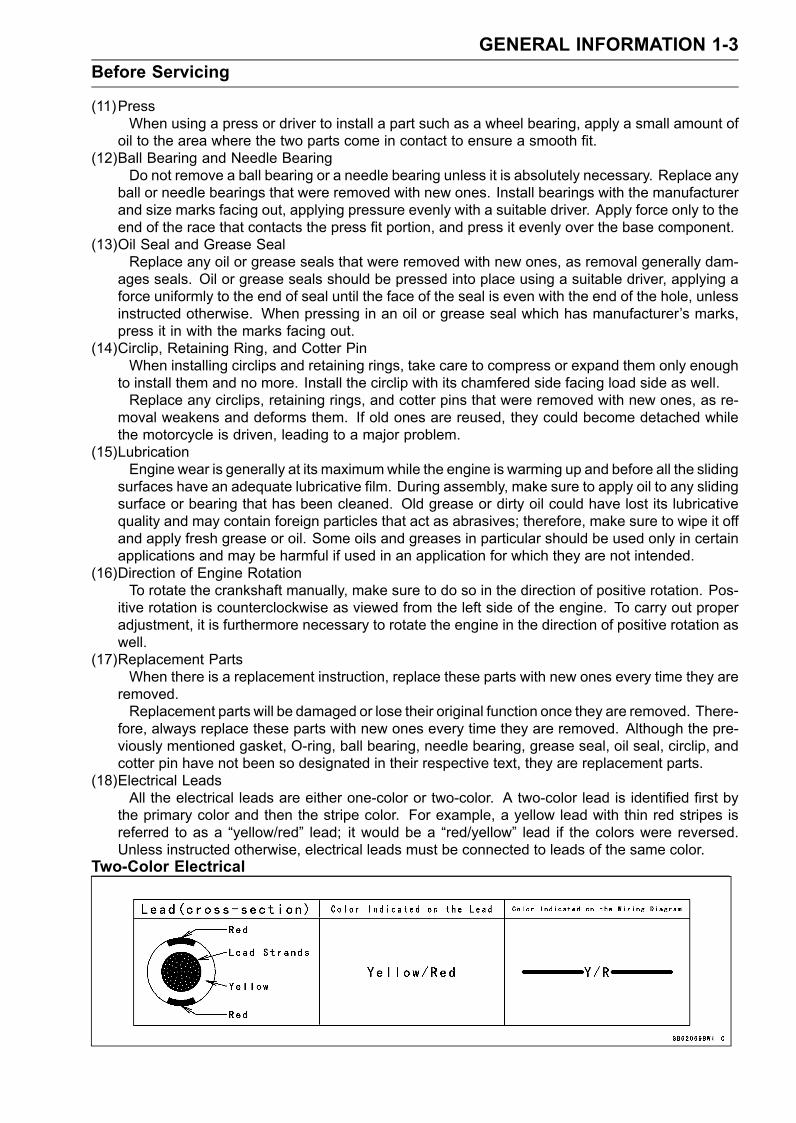
(18)Electrical LeadsAll the electrical leads are either one-color or two-color. A two-color lead is identified first by
the primary color and then the stripe color. For example, a yellow lead with thin red stripes isreferred to as a “yellow/red” lead; it would be a “red/yellow” lead if the colors were reversed.Unless instructed otherwise, electrical leads must be connected to leads of the same color.
Two-Color Electrical
1-4 GENERAL INFORMATIONBefore Servicing
(19)InspectionWhen parts have been disassembled, visually inspect these parts for the following conditions
or other damage. If there is any doubt as to the condition of them, replace them with new ones.Abrasion Crack Hardening WarpBent Dent Scratch WearColor change Deterioration Seizure
(20)SpecificationsSpecification terms are defined as follows:“Standards” show dimensions or performances which brand-new parts or systems have.“Service Limits” indicate the usable limits. If the measurement shows excessive wear or deteri-
orated performance, replace the damaged parts.
GENERAL INFORMATION 1-5Model Identification
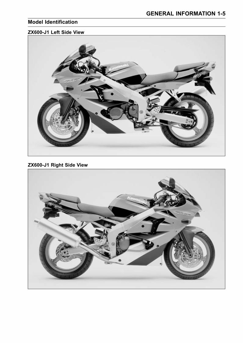
ZX600-J1 Left Side View
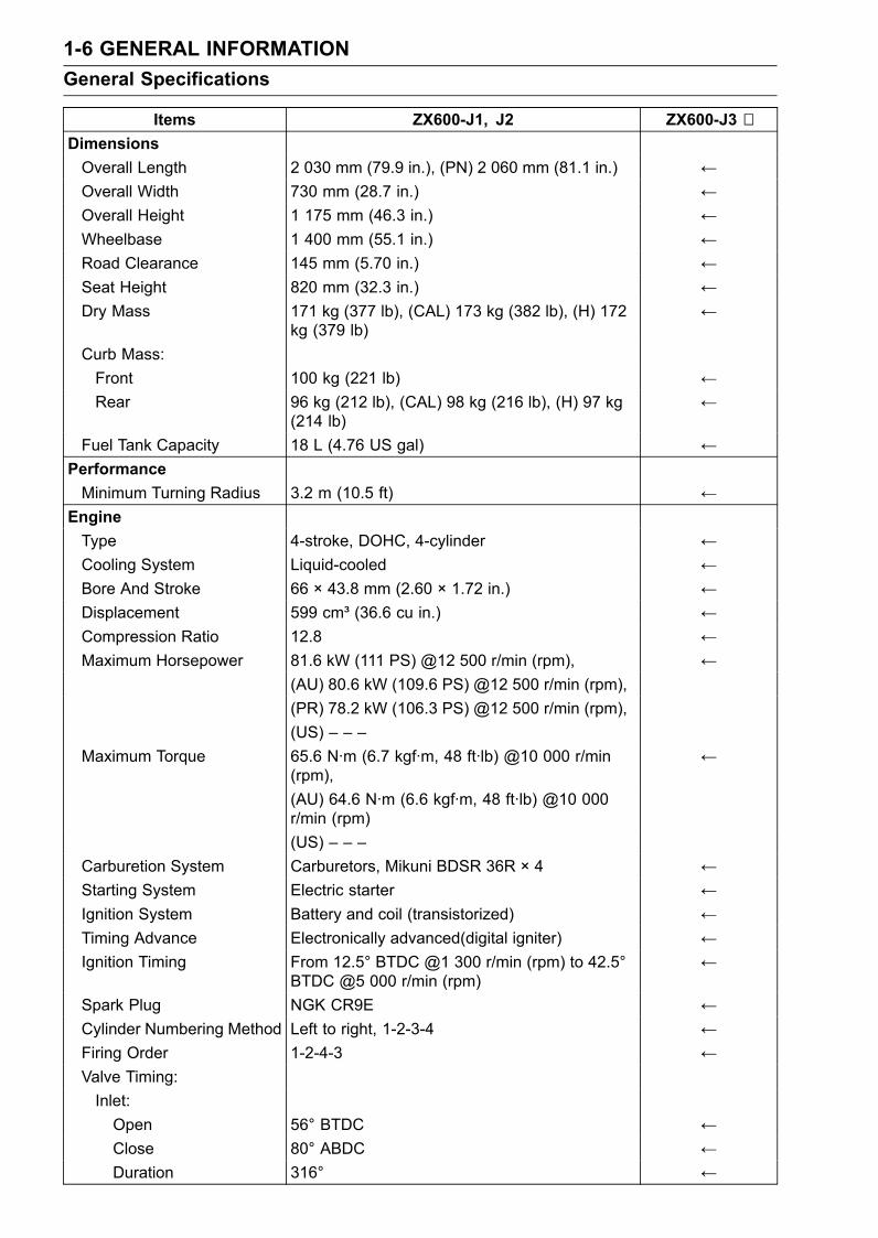
ZX600-J1 Right Side View
1-6 GENERAL INFORMATIONGeneral Specifications
Items ZX600-J1, J2 ZX600-J3 ∼DimensionsOverall Length 2 030 mm (79.9 in.), (PN) 2 060 mm (81.1 in.) ←Overall Width 730 mm (28.7 in.) ←Overall Height 1 175 mm (46.3 in.) ←Wheelbase 1 400 mm (55.1 in.) ←Road Clearance 145 mm (5.70 in.) ←Seat Height 820 mm (32.3 in.) ←Dry Mass 171 kg (377 lb), (CAL) 173 kg (382 lb), (H) 172
kg (379 lb)←
Curb Mass:Front 100 kg (221 lb) ←Rear 96 kg (212 lb), (CAL) 98 kg (216 lb), (H) 97 kg
(214 lb)←
Fuel Tank Capacity 18 L (4.76 US gal) ←PerformanceMinimum Turning Radius 3.2 m (10.5 ft) ←
EngineType 4-stroke, DOHC, 4-cylinder ←Cooling System Liquid-cooled ←Bore And Stroke 66 × 43.8 mm (2.60 × 1.72 in.) ←Displacement 599 cm³ (36.6 cu in.) ←Compression Ratio 12.8 ←Maximum Horsepower 81.6 kW (111 PS) @12 500 r/min (rpm), ←
(AU) 80.6 kW (109.6 PS) @12 500 r/min (rpm),(PR) 78.2 kW (106.3 PS) @12 500 r/min (rpm),(US) – – –
Maximum Torque 65.6 N·m (6.7 kgf·m, 48 ft·lb) @10 000 r/min(rpm),
←
(AU) 64.6 N·m (6.6 kgf·m, 48 ft·lb) @10 000r/min (rpm)(US) – – –
Carburetion System Carburetors, Mikuni BDSR 36R × 4 ←Starting System Electric starter ←Ignition System Battery and coil (transistorized) ←Timing Advance Electronically advanced(digital igniter) ←Ignition Timing From 12.5° BTDC @1 300 r/min (rpm) to 42.5°
BTDC @5 000 r/min (rpm)←
Spark Plug NGK CR9E ←Cylinder Numbering Method Left to right, 1-2-3-4 ←Firing Order 1-2-4-3 ←Valve Timing:Inlet:Open 56° BTDC ←Close 80° ABDC ←Duration 316° ←

GENERAL INFORMATION 1-7General Specifications
Items ZX600-J1, J2 ZX600-J3 ∼Exhaust:Open 61° BBDC ←Close 33° ATDC ←Duration 274° ←
Lubrication System Forced lubrication (wet sump with cooler) ←Engine Oil:Grade API SE, SF or SG ←
API SH, SJ with JASO MA (ZX600J1 ∼ J4, J6F)API SH, SJ or SL with JASO MA (ZX600J7F ∼ ) ←
Viscosity SAE10W-40, 10W-50, 20W-40, or 20W-50 SAE10W-40Capacity 4.0 L (4.23 US qt) ←
Drive TrainPrimary Reduction System:Type Gear ←Reduction Ratio 2.022 (89/44) ←
Clutch Type Wet multi disc ←Transmission:Type 6-speed, constant mesh, return shift ←Gear Ratios:1st 2.923 (38/13) ←2nd 2.062 (33/16) ←3rd 1.631 (31/19) ←4th 1.380 (29/21) ←5th 1.217 (28/23) ←6th 1.083 (26/24) ←
Final Drive System:Type Chain drive ←Reduction Ratio 2.666 (40/15) ←Overall Drive Ratio 5.843 @Top gear ←
FrameType Tubular, diamond ←Caster (Rake Angle) 23.5° ←Trail 95 mm (3.7 in.) ←Front Wheel:Tire Type Tubeless ←Tire Size 120/65 ZR17 (56 W) 120/65 ZR17 M/C
(56 W)Rim Size J 17M/C × MT3.50 ←
Rear Wheel:Tire Type Tubeless ←Tire Size 180/55 ZR17 (73 W) 180/55 ZR17
M/C (73 W)Rim Size J 17M/C × MT5.50 ←
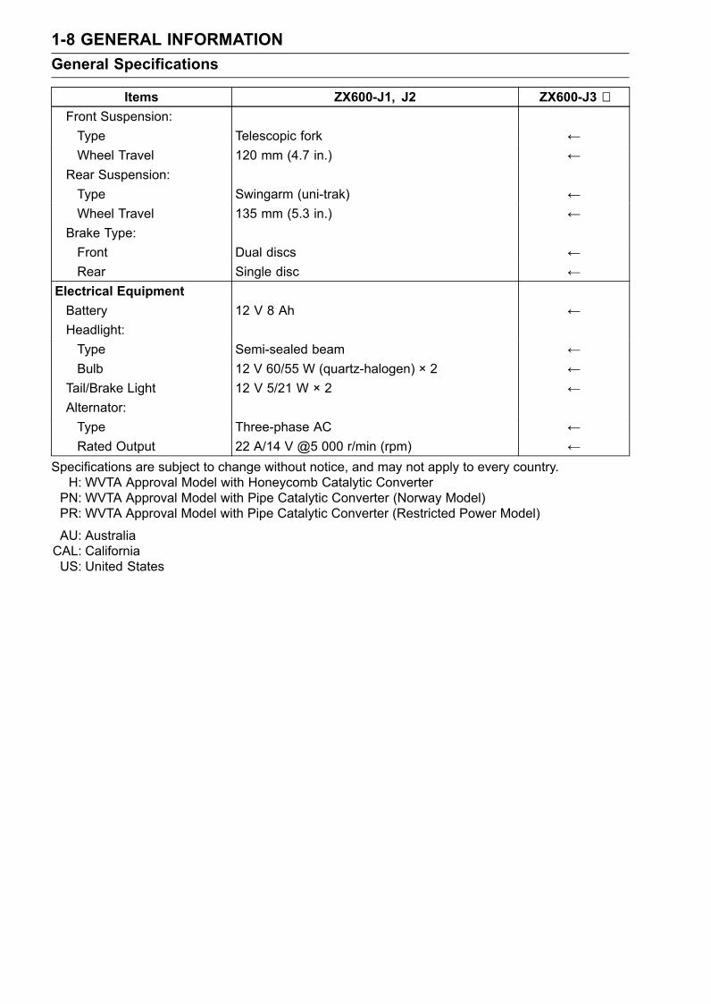
1-8 GENERAL INFORMATIONGeneral Specifications
Items ZX600-J1, J2 ZX600-J3 ∼Front Suspension:Type Telescopic fork ←Wheel Travel 120 mm (4.7 in.) ←
Rear Suspension:Type Swingarm (uni-trak) ←Wheel Travel 135 mm (5.3 in.) ←
Brake Type:Front Dual discs ←Rear Single disc ←
Electrical EquipmentBattery 12 V 8 Ah ←Headlight:Type Semi-sealed beam ←Bulb 12 V 60/55 W (quartz-halogen) × 2 ←
Tail/Brake Light 12 V 5/21 W × 2 ←Alternator:Type Three-phase AC ←Rated Output 22 A/14 V @5 000 r/min (rpm) ←
Specifications are subject to change without notice, and may not apply to every country.H: WVTA Approval Model with Honeycomb Catalytic ConverterPN: WVTA Approval Model with Pipe Catalytic Converter (Norway Model)PR: WVTA Approval Model with Pipe Catalytic Converter (Restricted Power Model)
AU: AustraliaCAL: CaliforniaUS: United States
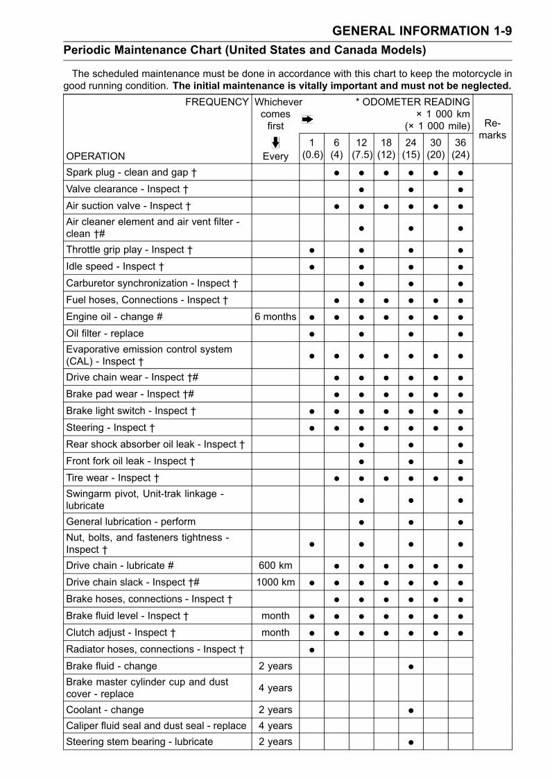
GENERAL INFORMATION 1-9Periodic Maintenance Chart (United States and Canada Models)
The scheduled maintenance must be done in accordance with this chart to keep the motorcycle ingood running condition. The initial maintenance is vitally important and must not be neglected.
FREQUENCY Whichevercomesfirst
* ODOMETER READING× 1 000 km
(× 1 000 mile)
OPERATION Every1(0.6)
6(4)
12(7.5)
18(12)
24(15)
30(20)
36(24)
Re-marks
Spark plug - clean and gap † • • • • • •Valve clearance - Inspect † • • •Air suction valve - Inspect † • • • • • •Air cleaner element and air vent filter -clean †# • • •Throttle grip play - Inspect † • • • •Idle speed - Inspect † • • • •Carburetor synchronization - Inspect † • • •Fuel hoses, Connections - Inspect † • • • • • •Engine oil - change # 6 months • • • • • • •Oil filter - replace • • • •Evaporative emission control system(CAL) - Inspect † • • • • • • •Drive chain wear - Inspect †# • • • • • •Brake pad wear - Inspect †# • • • • • •Brake light switch - Inspect † • • • • • • •Steering - Inspect † • • • • • • •Rear shock absorber oil leak - Inspect † • • •Front fork oil leak - Inspect † • • •Tire wear - Inspect † • • • • • •Swingarm pivot, Unit-trak linkage -lubricate • • •General lubrication - perform • • •Nut, bolts, and fasteners tightness -Inspect † • • • •Drive chain - lubricate # 600 km • • • • • •Drive chain slack - Inspect †# 1000 km • • • • • • •Brake hoses, connections - Inspect † • • • • • •Brake fluid level - Inspect † month • • • • • • •Clutch adjust - Inspect † month • • • • • • •Radiator hoses, connections - Inspect † •Brake fluid - change 2 years •Brake master cylinder cup and dustcover - replace 4 years
Coolant - change 2 years •Caliper fluid seal and dust seal - replace 4 yearsSteering stem bearing - lubricate 2 years •
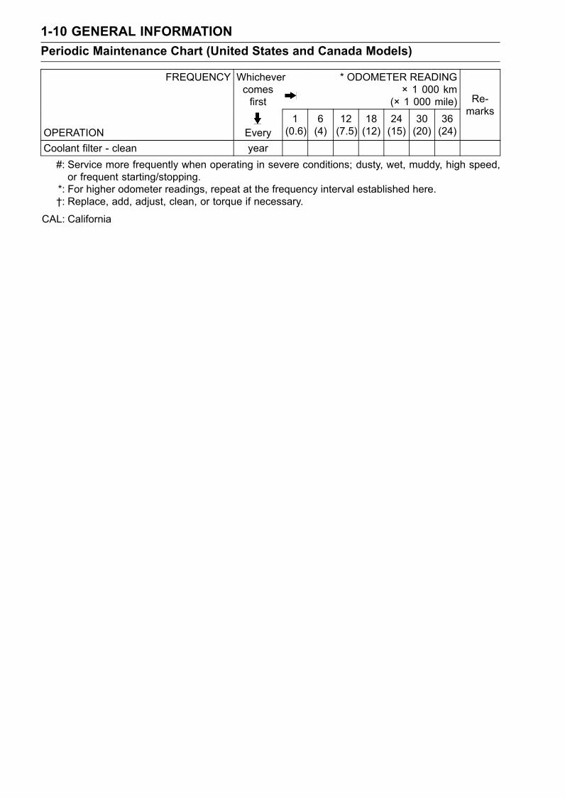
1-10 GENERAL INFORMATIONPeriodic Maintenance Chart (United States and Canada Models)
FREQUENCY Whichevercomesfirst
* ODOMETER READING× 1 000 km
(× 1 000 mile)
OPERATION Every1(0.6)
6(4)
12(7.5)
18(12)
24(15)
30(20)
36(24)
Re-marks
Coolant filter - clean year#: Service more frequently when operating in severe conditions; dusty, wet, muddy, high speed,or frequent starting/stopping.
*: For higher odometer readings, repeat at the frequency interval established here.†: Replace, add, adjust, clean, or torque if necessary.
CAL: California
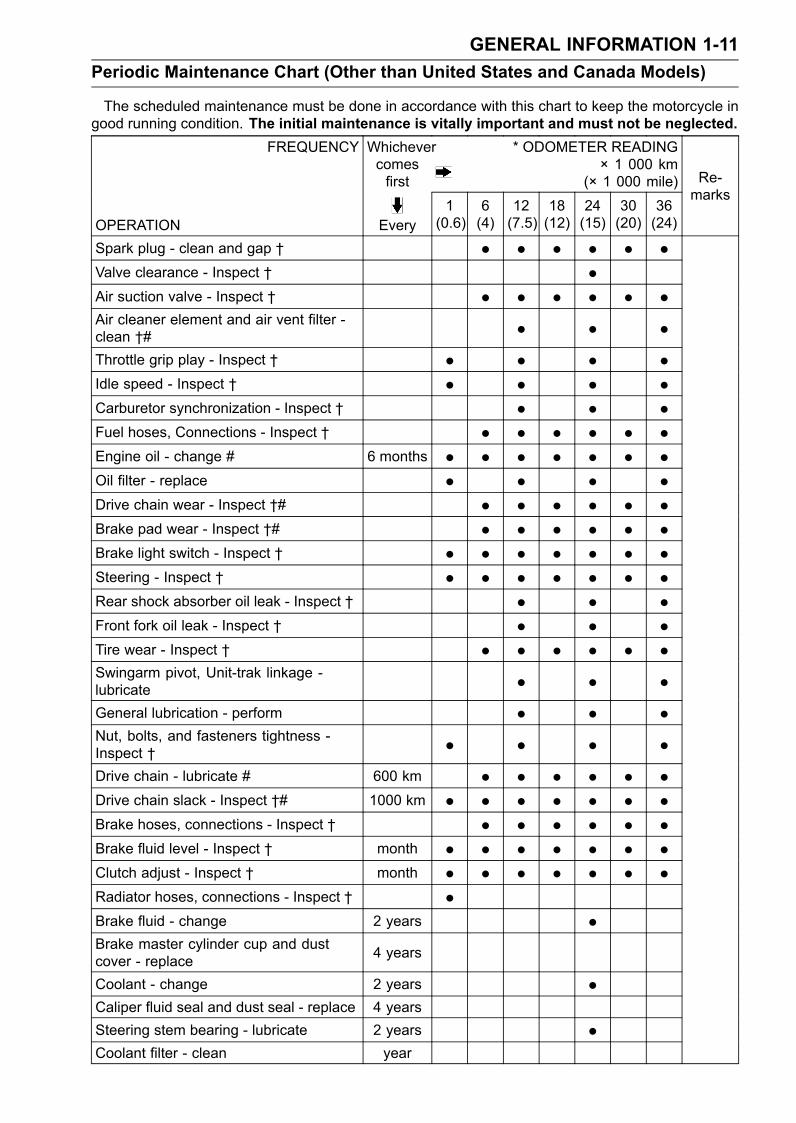
GENERAL INFORMATION 1-11Periodic Maintenance Chart (Other than United States and Canada Models)
The scheduled maintenance must be done in accordance with this chart to keep the motorcycle ingood running condition. The initial maintenance is vitally important and must not be neglected.
FREQUENCY Whichevercomesfirst
* ODOMETER READING× 1 000 km
(× 1 000 mile)
OPERATION Every1(0.6)
6(4)
12(7.5)
18(12)
24(15)
30(20)
36(24)
Re-marks
Spark plug - clean and gap † • • • • • •Valve clearance - Inspect † •Air suction valve - Inspect † • • • • • •Air cleaner element and air vent filter -clean †# • • •Throttle grip play - Inspect † • • • •Idle speed - Inspect † • • • •Carburetor synchronization - Inspect † • • •Fuel hoses, Connections - Inspect † • • • • • •Engine oil - change # 6 months • • • • • • •Oil filter - replace • • • •Drive chain wear - Inspect †# • • • • • •Brake pad wear - Inspect †# • • • • • •Brake light switch - Inspect † • • • • • • •Steering - Inspect † • • • • • • •Rear shock absorber oil leak - Inspect † • • •Front fork oil leak - Inspect † • • •Tire wear - Inspect † • • • • • •Swingarm pivot, Unit-trak linkage -lubricate • • •General lubrication - perform • • •Nut, bolts, and fasteners tightness -Inspect † • • • •Drive chain - lubricate # 600 km • • • • • •Drive chain slack - Inspect †# 1000 km • • • • • • •Brake hoses, connections - Inspect † • • • • • •Brake fluid level - Inspect † month • • • • • • •Clutch adjust - Inspect † month • • • • • • •Radiator hoses, connections - Inspect † •Brake fluid - change 2 years •Brake master cylinder cup and dustcover - replace 4 years
Coolant - change 2 years •Caliper fluid seal and dust seal - replace 4 yearsSteering stem bearing - lubricate 2 years •Coolant filter - clean year
1-12 GENERAL INFORMATIONPeriodic Maintenance Chart (Other than United States and Canada Models)
#: Service more frequently when operating in severe conditions; dusty, wet, muddy, high speed,or frequent starting/stopping.
*: For higher odometer readings, repeat at the frequency interval established here.†: Replace, add, adjust, clean, or torque if necessary.
GENERAL INFORMATION 1-13Technical Information-KLEEN (KAWASAKI LOW EXHAUST EMISSION)
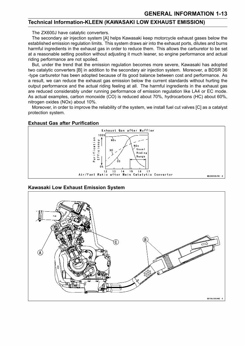
The ZX600J have catalytic converters.The secondary air injection system [A] helps Kawasaki keep motorcycle exhaust gases below the
established emission regulation limits. This system draws air into the exhaust ports, dilutes and burnsharmful ingredients in the exhaust gas in order to reduce them. This allows the carburetor to be setat a reasonable setting position without adjusting it much leaner, so engine performance and actualriding performance are not spoiled.But, under the trend that the emission regulation becomes more severe, Kawasaki has adopted
two catalytic converters [B] in addition to the secondary air injection system. Moreover, a BDSR 36-type carburetor has been adopted because of its good balance between cost and performance. Asa result, we can reduce the exhaust gas emission below the current standards without hurting theoutput performance and the actual riding feeling at all. The harmful ingredients in the exhaust gasare reduced considerably under running performance of emission regulation like LA4 or EC mode.As actual examples, carbon monoxide (CO) is reduced about 70%, hydrocarbons (HC) about 60%,nitrogen oxides (NOx) about 10%.Moreover, in order to improve the reliability of the system, we install fuel cut valves [C] as a catalyst
protection system.
Exhaust Gas after Purification
Kawasaki Low Exhaust Emission System
1-14 GENERAL INFORMATIONTechnical Information-KLEEN (KAWASAKI LOW EXHAUST EMISSION)
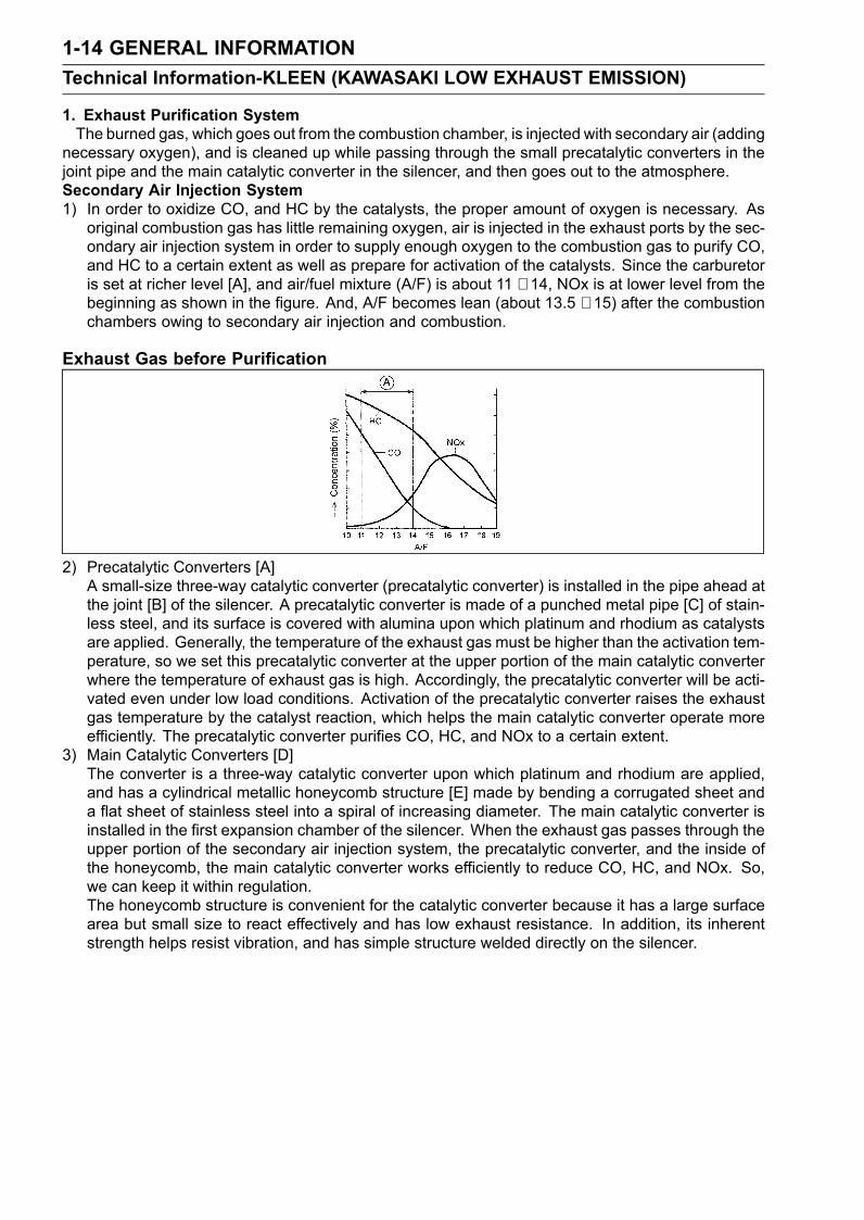
1. Exhaust Purification SystemThe burned gas, which goes out from the combustion chamber, is injected with secondary air (adding
necessary oxygen), and is cleaned up while passing through the small precatalytic converters in thejoint pipe and the main catalytic converter in the silencer, and then goes out to the atmosphere.Secondary Air Injection System1) In order to oxidize CO, and HC by the catalysts, the proper amount of oxygen is necessary. As
original combustion gas has little remaining oxygen, air is injected in the exhaust ports by the sec-ondary air injection system in order to supply enough oxygen to the combustion gas to purify CO,and HC to a certain extent as well as prepare for activation of the catalysts. Since the carburetoris set at richer level [A], and air/fuel mixture (A/F) is about 11 ∼ 14, NOx is at lower level from thebeginning as shown in the figure. And, A/F becomes lean (about 13.5 ∼ 15) after the combustionchambers owing to secondary air injection and combustion.
Exhaust Gas before Purification
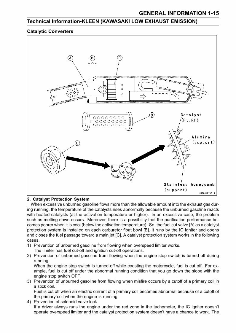
2) Precatalytic Converters [A]A small-size three-way catalytic converter (precatalytic converter) is installed in the pipe ahead atthe joint [B] of the silencer. A precatalytic converter is made of a punched metal pipe [C] of stain-less steel, and its surface is covered with alumina upon which platinum and rhodium as catalystsare applied. Generally, the temperature of the exhaust gas must be higher than the activation tem-perature, so we set this precatalytic converter at the upper portion of the main catalytic converterwhere the temperature of exhaust gas is high. Accordingly, the precatalytic converter will be acti-vated even under low load conditions. Activation of the precatalytic converter raises the exhaustgas temperature by the catalyst reaction, which helps the main catalytic converter operate moreefficiently. The precatalytic converter purifies CO, HC, and NOx to a certain extent.
3) Main Catalytic Converters [D]The converter is a three-way catalytic converter upon which platinum and rhodium are applied,and has a cylindrical metallic honeycomb structure [E] made by bending a corrugated sheet anda flat sheet of stainless steel into a spiral of increasing diameter. The main catalytic converter isinstalled in the first expansion chamber of the silencer. When the exhaust gas passes through theupper portion of the secondary air injection system, the precatalytic converter, and the inside ofthe honeycomb, the main catalytic converter works efficiently to reduce CO, HC, and NOx. So,we can keep it within regulation.The honeycomb structure is convenient for the catalytic converter because it has a large surfacearea but small size to react effectively and has low exhaust resistance. In addition, its inherentstrength helps resist vibration, and has simple structure welded directly on the silencer.
GENERAL INFORMATION 1-15Technical Information-KLEEN (KAWASAKI LOW EXHAUST EMISSION)
Catalytic Converters
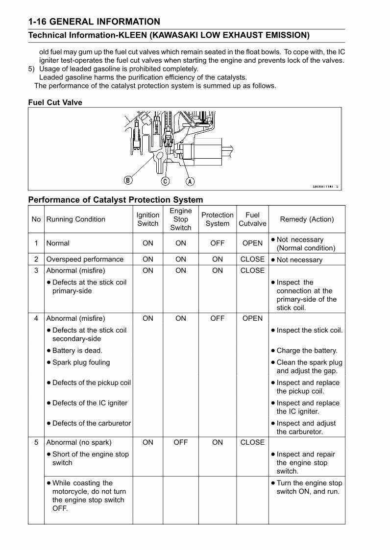
2. Catalyst Protection SystemWhen excessive unburned gasoline flows more than the allowable amount into the exhaust gas dur-
ing running, the temperature of the catalysts rises abnormally because the unburned gasoline reactswith heated catalysts (at the activation temperature or higher). In an excessive case, the problemsuch as melting-down occurs. Moreover, there is a possibility that the purification performance be-comes poorer when it is cool (below the activation temperature). So, the fuel cut valve [A] as a catalystprotection system is installed on each carburetor float bowl [B]. It runs by the IC Igniter and opensand closes the fuel passage toward a main jet [C]. A catalyst protection system works in the followingcases.1) Prevention of unburned gasoline from flowing when overspeed limiter works.
The limiter has fuel cut-off and ignition cut-off operations.2) Prevention of unburned gasoline from flowing when the engine stop switch is turned off during
running.When the engine stop switch is turned off while coasting the motorcycle, fuel is cut off. For ex-ample, fuel is cut off under the abnormal running condition that you go down the slope with theengine stop switch OFF.
3) Prevention of unburned gasoline from flowing when misfire occurs by a cutoff of a primary coil ina stick coil.Fuel is cut off when an electric current of a primary coil becomes abnormal because of a cutoff ofthe primary coil when the engine is running.
4) Prevention of solenoid valve lockIf a driver always runs the engine under the red zone in the tachometer, the IC igniter doesn’toperate overspeed limiter and the catalyst protection system doesn’t have a chance to work. The
1-16 GENERAL INFORMATIONTechnical Information-KLEEN (KAWASAKI LOW EXHAUST EMISSION)
old fuel may gum up the fuel cut valves which remain seated in the float bowls. To cope with, the ICigniter test-operates the fuel cut valves when starting the engine and prevents lock of the valves.
5) Usage of leaded gasoline is prohibited completely.Leaded gasoline harms the purification efficiency of the catalysts.The performance of the catalyst protection system is summed up as follows.
Fuel Cut Valve
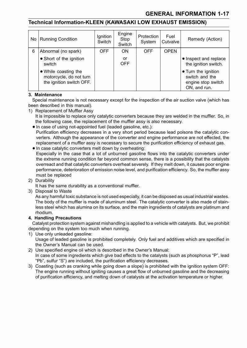
Performance of Catalyst Protection System
No Running Condition IgnitionSwitch
EngineStopSwitch
ProtectionSystem
FuelCutvalve Remedy (Action)
1 Normal ON ON OFF OPEN •Not necessary(Normal condition)
2 Overspeed performance ON ON ON CLOSE •Not necessary3 Abnormal (misfire) ON ON ON CLOSE
•Defects at the stick coilprimary-side
• Inspect theconnection at theprimary-side of thestick coil.
4 Abnormal (misfire) ON ON OFF OPEN
•Defects at the stick coilsecondary-side
• Inspect the stick coil.
• Battery is dead. • Charge the battery.• Spark plug fouling •Clean the spark plug
and adjust the gap.
• Defects of the pickup coil • Inspect and replacethe pickup coil.
• Defects of the IC igniter • Inspect and replacethe IC igniter.
• Defects of the carburetor • Inspect and adjustthe carburetor.
5 Abnormal (no spark) ON OFF ON CLOSE
•Short of the engine stopswitch
• Inspect and repairthe engine stopswitch.
•While coasting themotorcycle, do not turnthe engine stop switchOFF.
• Turn the engine stopswitch ON, and run.
GENERAL INFORMATION 1-17Technical Information-KLEEN (KAWASAKI LOW EXHAUST EMISSION)
No Running Condition IgnitionSwitch
EngineStopSwitch
ProtectionSystem
FuelCutvalve Remedy (Action)
6 Abnormal (no spark) OFF ON OFF OPEN
•Short of the ignitionswitch
orOFF
• Inspect and replacethe ignition switch.
•While coasting themotorcycle, do not turnthe ignition switch OFF.
• Turn the ignitionswitch and theengine stop switchON, and run.
3. MaintenanceSpecial maintenance is not necessary except for the inspection of the air suction valve (which has
been described in this manual).1) Replacement of Muffler Assy
It is impossible to replace only catalytic converters because they are welded in the muffler. So, inthe following case, the replacement of the muffler assy is also necessary.• In case of using not-appointed fuel (leaded gasoline, etc.):Purification efficiency decreases in a very short period because lead poisons the catalytic con-verters. Although the appearance of the converter and engine performance are not effected, thereplacement of a muffler assy is necessary to secure the purification efficiency of exhaust gas.• In case catalytic converters melt down by overheating:Especially in the case that a lot of unburned gasoline flows into the catalytic converters underthe extreme running condition far beyond common sense, there is a possibility that the catalystsoverreact and that catalytic converters overheat severely. If they melt down, it causes poor engineperformance, deterioration of emission noise level, and purification efficiency. So, the muffler assymust be replaced
2) DurabilityIt has the same durability as a conventional muffler.
3) Disposal to WasteAs any harmful toxic substance is not used especially, it can be disposed as usual industrial wastes.The body of the muffler is made of aluminum steel. The catalytic converter is also made of stain-less steel which has alumina on its surface, and the main ingredients of catalysts are platinum andrhodium.
4. Handling PrecautionsCatalyst protection system against mishandling is applied to a vehicle with catalysts. But, we prohibit
depending on the system too much when running.1) Use only unleaded gasoline:
Usage of leaded gasoline is prohibited completely. Only fuel and additives which are specified inthe Owner’s Manual can be used.
2) Use specified engine oil which is described in the Owner’s Manual:In case of some ingredients which give bad effects to the catalysts (such as phosphorus “P”, lead“Pb”, sulfur “S”) are included, the purification efficiency decreases.
3) Coasting (such as cranking while going down a slope) is prohibited with the ignition system OFF:The engine running without igniting causes a great flow of unburned gasoline and the decreasingof purification efficiency, and melting down of catalysts at the activation temperature or higher.
1-18 GENERAL INFORMATIONTechnical Information-KLEEN (KAWASAKI LOW EXHAUST EMISSION)
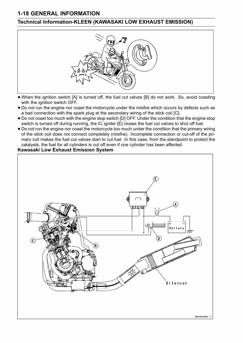
•When the ignition switch [A] is turned off, the fuel cut valves [B] do not work. So, avoid coastingwith the ignition switch OFF.•Do not run the engine nor coast the motorcycle under the misfire which occurs by defects such asa bad connection with the spark plug at the secondary wiring of the stick coil [C].• Do not coast too much with the engine stop switch [D] OFF. Under the condition that the engine stopswitch is turned off during running, the IC igniter [E] closes the fuel cut valves to shut off fuel.• Do not run the engine nor coast the motorcycle too much under the condition that the primary wiringof the stick coil does not connect completely (misfire). Incomplete connection or cut-off of the pri-mary coil makes the fuel cut valves start to cut fuel. In this case, from the standpoint to protect thecatalysts, the fuel for all cylinders is cut off even if one cylinder has been affected.
Kawasaki Low Exhaust Emission System
GENERAL INFORMATION 1-19Technical Information-KLEEN (KAWASAKI LOW EXHAUST EMISSION)
•Do not run overspeed limiter too much from the standpoint to protect the engine. (Overspeed limiterhas a protection system that applies ignition cut method and fuel cut method together. Conventionalsystem applies fuel-on method.)•Do not run the engine even if only one cylinder has a misfire or has unstable running. In this case,request the nearest service facility to correct it. If you have no choice but running by yourself, keepengine rpm as low as possible and try to finish running at the shortest period.•When the battery is dead, do not push-start. Connect another full-charged battery with jumper ca-bles, and start the engine.
5. Additional Information1) Secondary Air Injection SystemThe mechanism is simple and power loss is minimum because the system uses the vacuum pres-
sure created by exhaust pulses.The secondary injection air helps the fuel/air mixture burn more completely (Primary air means air
which flows through the inlet pipe). As the exhaust valve opens, and the burned fuel passes theexhaust valve, a stream of fresh air is introduced through the air suction valve. This fresh air burnsthe unburned gas and converts the carbon monoxide (CO) and hydrocarbons (HC) into harmlesscarbon dioxide (CO2) and water (H2O).CO + 1/2 O2 → CO2HC + O2 → CO2 + H2OThe secondary air injection system consists of a vacuum switch valve, and two air suction valves.
Without using an air pump, the air suction valve can draw fresh air into the exhaust passage near theexhaust valves by vacuum that exhaust pulses generate.Air Suction ValvesThe air suction valves is a check valve which allows fresh air to flow only from the air cleaner via
air hoses into the exhaust port and prevents return flow. Remove and inspect the air suction valvesperiodically (see Engine Top End chapter in this Service Manual). Also, remove and inspect the airsuction valves whenever the idle speed is unstable, engine power is greatly reduced, or there areabnormal engine noises.Vacuum Switch ValveAlthough the vacuum switch valve usually permits secondary air flow, it closes when a high vacuum
(low pressure) is developed at the inlet pipe during engine braking. This is to shut off secondary airflow and prevent explosions in the exhaust ports which might be caused by extra unburned fuel in theexhaust during deceleration. These explosions, or backfiring in the exhaust system could damagethe air suction valves.Regular inspection of the vacuum switch valve is not needed. If backfiring occurs frequently in the
exhaust system during engine braking or if there are abnormal engine noises, check the vacuumswitch valve as described in the text (see Engine Top End chapter in this Service Manual).
1-20 GENERAL INFORMATIONTechnical Information-KLEEN (KAWASAKI LOW EXHAUST EMISSION)
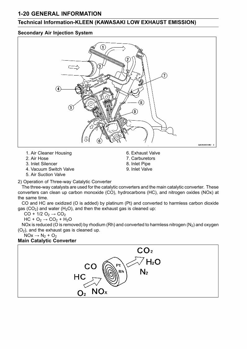
Secondary Air Injection System
1. Air Cleaner Housing2. Air Hose3. Inlet Silencer4. Vacuum Switch Valve5. Air Suction Valve
6. Exhaust Valve7. Carburetors8. Inlet Pipe9. Inlet Valve
2) Operation of Three-way Catalytic ConverterThe three-way catalysts are used for the catalytic converters and the main catalytic converter. These
converters can clean up carbon monoxide (CO), hydrocarbons (HC), and nitrogen oxides (NOx) atthe same time.CO and HC are oxidized (O is added) by platinum (Pt) and converted to harmless carbon dioxide
gas (CO2) and water (H2O), and then the exhaust gas is cleaned up:CO + 1/2 O2 → CO2HC + O2 → CO2 + H2ONOx is reduced (O is removed) by rhodium (Rh) and converted to harmless nitrogen (N2) and oxygen
(O2), and the exhaust gas is cleaned up.NOx → N2 + O2
Main Catalytic Converter
GENERAL INFORMATION 1-21Technical Information-KLEEN (KAWASAKI LOW EXHAUST EMISSION)
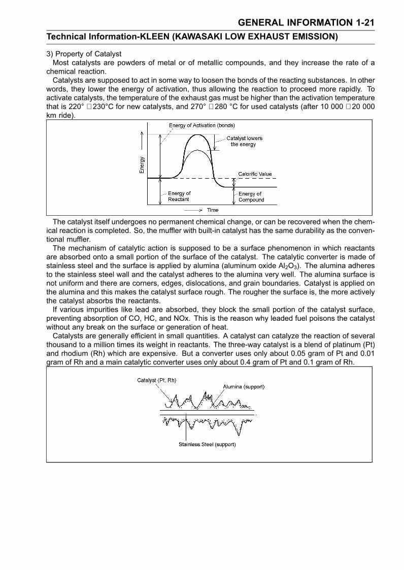
3) Property of CatalystMost catalysts are powders of metal or of metallic compounds, and they increase the rate of a
chemical reaction.Catalysts are supposed to act in some way to loosen the bonds of the reacting substances. In other
words, they lower the energy of activation, thus allowing the reaction to proceed more rapidly. Toactivate catalysts, the temperature of the exhaust gas must be higher than the activation temperaturethat is 220° ∼ 230°C for new catalysts, and 270° ∼ 280 °C for used catalysts (after 10 000 ∼ 20 000km ride).
The catalyst itself undergoes no permanent chemical change, or can be recovered when the chem-ical reaction is completed. So, the muffler with built-in catalyst has the same durability as the conven-tional muffler.The mechanism of catalytic action is supposed to be a surface phenomenon in which reactants
are absorbed onto a small portion of the surface of the catalyst. The catalytic converter is made ofstainless steel and the surface is applied by alumina (aluminum oxide Al2O3). The alumina adheresto the stainless steel wall and the catalyst adheres to the alumina very well. The alumina surface isnot uniform and there are corners, edges, dislocations, and grain boundaries. Catalyst is applied onthe alumina and this makes the catalyst surface rough. The rougher the surface is, the more activelythe catalyst absorbs the reactants.If various impurities like lead are absorbed, they block the small portion of the catalyst surface,
preventing absorption of CO, HC, and NOx. This is the reason why leaded fuel poisons the catalystwithout any break on the surface or generation of heat.Catalysts are generally efficient in small quantities. A catalyst can catalyze the reaction of several
thousand to a million times its weight in reactants. The three-way catalyst is a blend of platinum (Pt)and rhodium (Rh) which are expensive. But a converter uses only about 0.05 gram of Pt and 0.01gram of Rh and a main catalytic converter uses only about 0.4 gram of Pt and 0.1 gram of Rh.
1-22 GENERAL INFORMATIONTechnical Information - Non-Contact Hall IC-Type Speed Sensor
DetailsThe electronic combination meter unit, superior to the
conventional type in weight and durability is installed onthe ZX600-J. The hall IC-type speed sensor is installed onthe ZX600-J together with it, which needs no cable andspeedometer gears. Its construction and operation are de-scribed as follows;
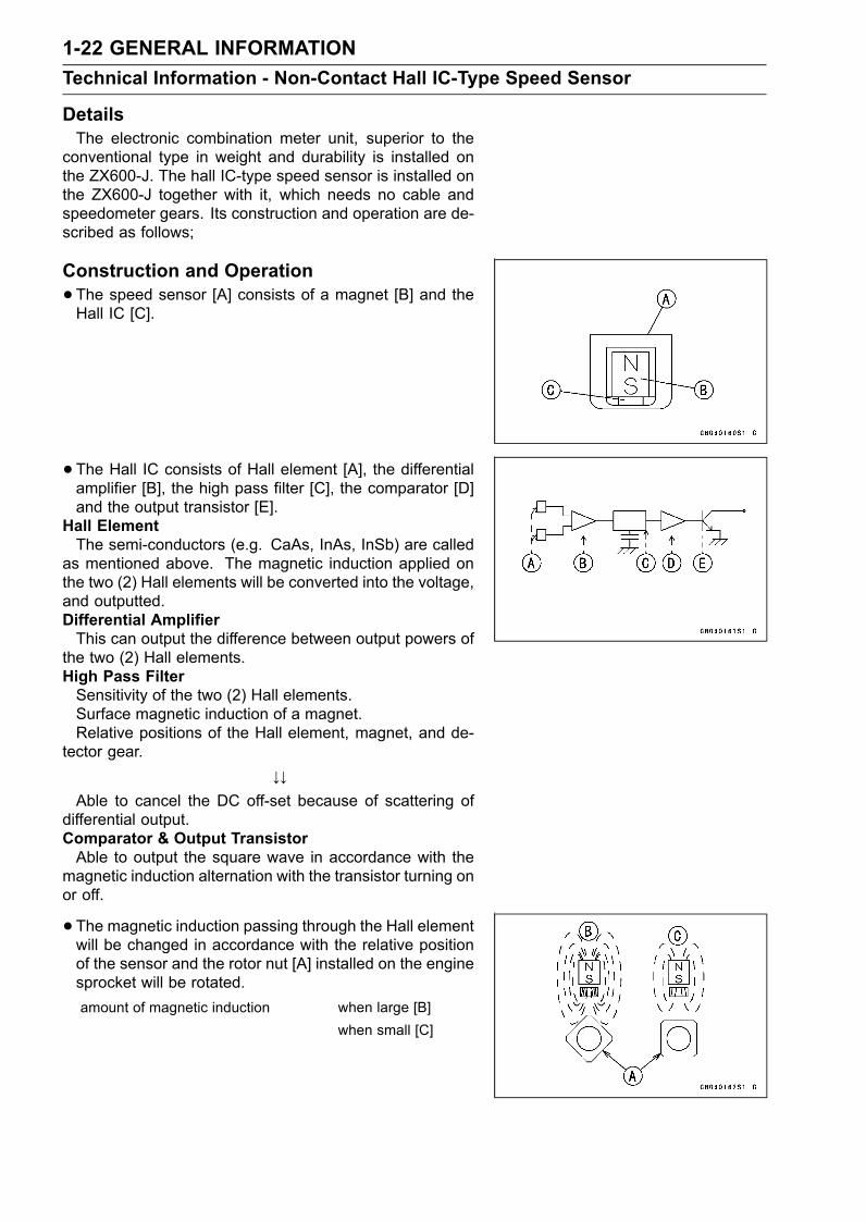
Construction and Operation•The speed sensor [A] consists of a magnet [B] and theHall IC [C].
• The Hall IC consists of Hall element [A], the differentialamplifier [B], the high pass filter [C], the comparator [D]and the output transistor [E].
Hall ElementThe semi-conductors (e.g. CaAs, InAs, InSb) are called
as mentioned above. The magnetic induction applied onthe two (2) Hall elements will be converted into the voltage,and outputted.Differential AmplifierThis can output the difference between output powers of
the two (2) Hall elements.High Pass FilterSensitivity of the two (2) Hall elements.Surface magnetic induction of a magnet.Relative positions of the Hall element, magnet, and de-
tector gear.↓↓
Able to cancel the DC off-set because of scattering ofdifferential output.Comparator & Output TransistorAble to output the square wave in accordance with the
magnetic induction alternation with the transistor turning onor off.
• The magnetic induction passing through the Hall elementwill be changed in accordance with the relative positionof the sensor and the rotor nut [A] installed on the enginesprocket will be rotated.amount of magnetic induction when large [B]
when small [C]
GENERAL INFORMATION 1-23Technical Information - Non-Contact Hall IC-Type Speed Sensor
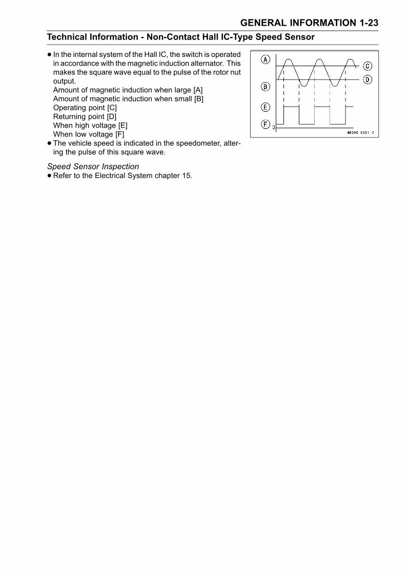
• In the internal system of the Hall IC, the switch is operatedin accordance with themagnetic induction alternator. Thismakes the square wave equal to the pulse of the rotor nutoutput.Amount of magnetic induction when large [A]Amount of magnetic induction when small [B]Operating point [C]Returning point [D]When high voltage [E]When low voltage [F]• The vehicle speed is indicated in the speedometer, alter-ing the pulse of this square wave.
Speed Sensor Inspection•Refer to the Electrical System chapter 15.
1-24 GENERAL INFORMATIONTechnical Information - Alternator Made from Rare Magnet
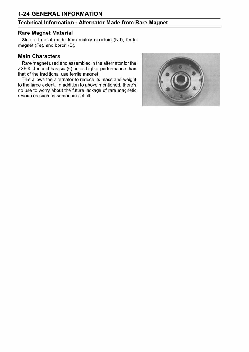
Rare Magnet MaterialSintered metal made from mainly neodium (Nd), ferric
magnet (Fe), and boron (B).
Main CharactersRare magnet used and assembled in the alternator for the
ZX600-J model has six (6) times higher performance thanthat of the traditional use ferrite magnet.This allows the alternator to reduce its mass and weight
to the large extent. In addition to above mentioned, there’sno use to worry about the future lackage of rare magneticresources such as samarium cobalt.
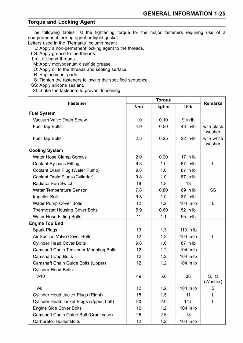
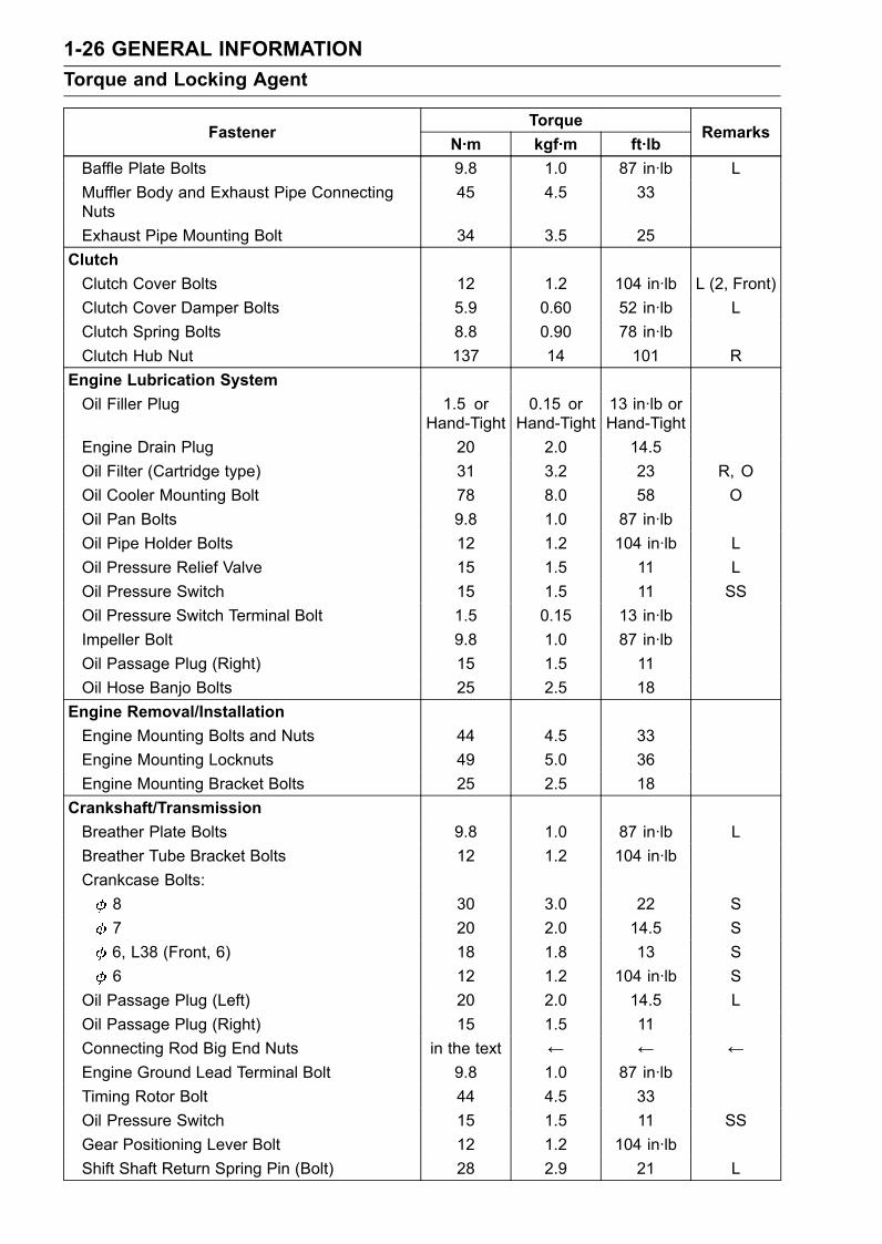
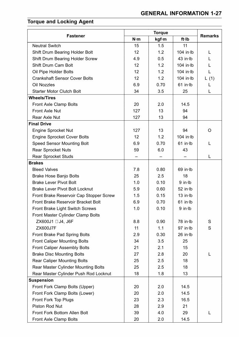
GENERAL INFORMATION 1-25Torque and Locking Agent
The following tables list the tightening torque for the major fasteners requiring use of anon-permanent locking agent or liquid gasket.Letters used in the “Remarks” column mean:L: Apply a non-permanent locking agent to the threads.
LG: Apply grease to the threads.Lh: Left-hand threads.M: Apply molybdenum disulfide grease.O: Apply oil to the threads and seating surface.R: Replacement partsS: Tighten the fasteners following the specified sequence.SS: Apply silicone sealant.St: Stake the fasteners to prevent loosening.
TorqueFastener
N·m kgf·m ft·lbRemarks
Fuel SystemVacuum Valve Drain Screw 1.0 0.10 9 in·lbFuel Tap Bolts 4.9 0.50 43 in·lb with black
washerFuel Tap Bolts 2.5 0.25 22 in·lb with white
washerCooling SystemWater Hose Clamp Screws 2.0 0.20 17 in·lbCoolant By-pass Fitting 9.8 1.0 87 in·lb LCoolant Drain Plug (Water Pump) 9.8 1.0 87 in·lbCoolant Drain Plugs (Cylinder) 9.8 1.0 87 in·lbRadiator Fan Switch 18 1.8 13Water Temperature Sensor 7.8 0.80 69 in·lb SSImpeller Bolt 9.8 1.0 87 in·lbWater Pump Cover Bolts 12 1.2 104 in·lb LThermostat Housing Cover Bolts 5.9 0.60 52 in·lbWater Hose Fitting Bolts 11 1.1 95 in·lb
Engine Top EndSpark Plugs 13 1.3 113 in·lbAir Suction Valve Cover Bolts 12 1.2 104 in·lb LCylinder Head Cover Bolts 9.8 1.0 87 in·lbCamshaft Chain Tensioner Mounting Bolts 12 1.2 104 in·lbCamshaft Cap Bolts 12 1.2 104 in·lbCamshaft Chain Guide Bolts (Upper) 12 1.2 104 in·lbCylinder Head Bolts:
10 49 5.0 36 S, O(Washer)
6 12 1.2 104 in·lb SCylinder Head Jacket Plugs (Right) 15 1.5 11 LCylinder Head Jacket Plugs (Upper, Left) 20 2.0 14.5 LEngine Side Cover Bolts 12 1.2 104 in·lbCamshaft Chain Guide Bolt (Crankcase) 25 2.5 18Carburetor Holder Bolts 12 1.2 104 in·lb
1-26 GENERAL INFORMATIONTorque and Locking Agent
TorqueFastener
N·m kgf·m ft·lbRemarks
Baffle Plate Bolts 9.8 1.0 87 in·lb LMuffler Body and Exhaust Pipe ConnectingNuts
45 4.5 33
Exhaust Pipe Mounting Bolt 34 3.5 25ClutchClutch Cover Bolts 12 1.2 104 in·lb L (2, Front)Clutch Cover Damper Bolts 5.9 0.60 52 in·lb LClutch Spring Bolts 8.8 0.90 78 in·lbClutch Hub Nut 137 14 101 R
Engine Lubrication SystemOil Filler Plug 1.5 or
Hand-Tight0.15 or
Hand-Tight13 in·lb orHand-Tight
Engine Drain Plug 20 2.0 14.5Oil Filter (Cartridge type) 31 3.2 23 R, OOil Cooler Mounting Bolt 78 8.0 58 OOil Pan Bolts 9.8 1.0 87 in·lbOil Pipe Holder Bolts 12 1.2 104 in·lb LOil Pressure Relief Valve 15 1.5 11 LOil Pressure Switch 15 1.5 11 SSOil Pressure Switch Terminal Bolt 1.5 0.15 13 in·lbImpeller Bolt 9.8 1.0 87 in·lbOil Passage Plug (Right) 15 1.5 11Oil Hose Banjo Bolts 25 2.5 18
Engine Removal/InstallationEngine Mounting Bolts and Nuts 44 4.5 33Engine Mounting Locknuts 49 5.0 36Engine Mounting Bracket Bolts 25 2.5 18
Crankshaft/TransmissionBreather Plate Bolts 9.8 1.0 87 in·lb LBreather Tube Bracket Bolts 12 1.2 104 in·lbCrankcase Bolts:
8 30 3.0 22 S7 20 2.0 14.5 S6, L38 (Front, 6) 18 1.8 13 S6 12 1.2 104 in·lb S
Oil Passage Plug (Left) 20 2.0 14.5 LOil Passage Plug (Right) 15 1.5 11Connecting Rod Big End Nuts in the text ← ← ←Engine Ground Lead Terminal Bolt 9.8 1.0 87 in·lbTiming Rotor Bolt 44 4.5 33Oil Pressure Switch 15 1.5 11 SSGear Positioning Lever Bolt 12 1.2 104 in·lbShift Shaft Return Spring Pin (Bolt) 28 2.9 21 L
GENERAL INFORMATION 1-27Torque and Locking Agent
TorqueFastener
N·m kgf·m ft·lbRemarks
Neutral Switch 15 1.5 11Shift Drum Bearing Holder Bolt 12 1.2 104 in·lb LShift Drum Bearing Holder Screw 4.9 0.5 43 in·lb LShift Drum Cam Bolt 12 1.2 104 in·lb LOil Pipe Holder Bolts 12 1.2 104 in·lb LCrankshaft Sensor Cover Bolts 12 1.2 104 in·lb L (1)Oil Nozzles 6.9 0.70 61 in·lb LStarter Motor Clutch Bolt 34 3.5 25 L
Wheels/TiresFront Axle Clamp Bolts 20 2.0 14.5Front Axle Nut 127 13 94Rear Axle Nut 127 13 94
Final DriveEngine Sprocket Nut 127 13 94 OEngine Sprocket Cover Bolts 12 1.2 104 in·lbSpeed Sensor Mounting Bolt 6.9 0.70 61 in·lb LRear Sprocket Nuts 59 6.0 43Rear Sprocket Studs – – – L
BrakesBleed Valves 7.8 0.80 69 in·lbBrake Hose Banjo Bolts 25 2.5 18Brake Lever Pivot Bolt 1.0 0.10 9 in·lbBrake Lever Pivot Bolt Locknut 5.9 0.60 52 in·lbFront Brake Reservoir Cap Stopper Screw 1.5 0.15 13 in·lbFront Brake Reservoir Bracket Bolt 6.9 0.70 61 in·lbFront Brake Light Switch Screws 1.0 0.10 9 in·lbFront Master Cylinder Clamp BoltsZX600J1 ∼ J4, J6F 8.8 0.90 78 in·lb SZX600J7F 11 1.1 97 in·lb S
Front Brake Pad Spring Bolts 2.9 0.30 26 in·lbFront Caliper Mounting Bolts 34 3.5 25Front Caliper Assembly Bolts 21 2.1 15Brake Disc Mounting Bolts 27 2.8 20 LRear Caliper Mounting Bolts 25 2.5 18Rear Master Cylinder Mounting Bolts 25 2.5 18Rear Master Cylinder Push Rod Locknut 18 1.8 13
SuspensionFront Fork Clamp Bolts (Upper) 20 2.0 14.5Front Fork Clamp Bolts (Lower) 20 2.0 14.5Front Fork Top Plugs 23 2.3 16.5Piston Rod Nut 28 2.9 21Front Fork Bottom Allen Bolt 39 4.0 29 LFront Axle Clamp Bolts 20 2.0 14.5
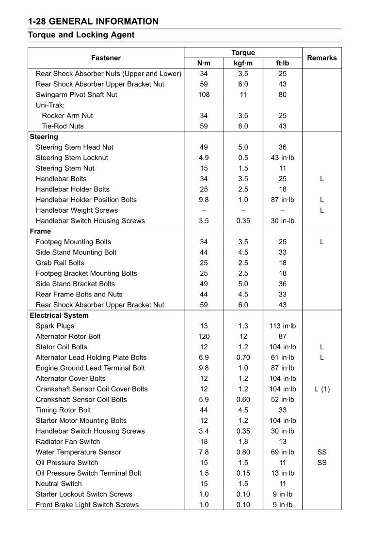
1-28 GENERAL INFORMATIONTorque and Locking Agent
TorqueFastener
N·m kgf·m ft·lbRemarks
Rear Shock Absorber Nuts (Upper and Lower) 34 3.5 25Rear Shock Absorber Upper Bracket Nut 59 6.0 43Swingarm Pivot Shaft Nut 108 11 80Uni-Trak:Rocker Arm Nut 34 3.5 25Tie-Rod Nuts 59 6.0 43
SteeringSteering Stem Head Nut 49 5.0 36Steering Stem Locknut 4.9 0.5 43 in·lbSteering Stem Nut 15 1.5 11Handlebar Bolts 34 3.5 25 LHandlebar Holder Bolts 25 2.5 18Handlebar Holder Position Bolts 9.8 1.0 87 in·lb LHandlebar Weight Screws – – – LHandlebar Switch Housing Screws 3.5 0.35 30 in-lb
FrameFootpeg Mounting Bolts 34 3.5 25 LSide Stand Mounting Bolt 44 4.5 33Grab Rail Bolts 25 2.5 18Footpeg Bracket Mounting Bolts 25 2.5 18Side Stand Bracket Bolts 49 5.0 36Rear Frame Bolts and Nuts 44 4.5 33Rear Shock Absorber Upper Bracket Nut 59 6.0 43
Electrical SystemSpark Plugs 13 1.3 113 in·lbAlternator Rotor Bolt 120 12 87Stator Coil Bolts 12 1.2 104 in·lb LAlternator Lead Holding Plate Bolts 6.9 0.70 61 in·lb LEngine Ground Lead Terminal Bolt 9.8 1.0 87 in·lbAlternator Cover Bolts 12 1.2 104 in·lbCrankshaft Sensor Coil Cover Bolts 12 1.2 104 in·lb L (1)Crankshaft Sensor Coil Bolts 5.9 0.60 52 in·lbTiming Rotor Bolt 44 4.5 33Starter Motor Mounting Bolts 12 1.2 104 in·lbHandlebar Switch Housing Screws 3.4 0.35 30 in·lbRadiator Fan Switch 18 1.8 13Water Temperature Sensor 7.8 0.80 69 in·lb SSOil Pressure Switch 15 1.5 11 SSOil Pressure Switch Terminal Bolt 1.5 0.15 13 in·lbNeutral Switch 15 1.5 11Starter Lockout Switch Screws 1.0 0.10 9 in·lbFront Brake Light Switch Screws 1.0 0.10 9 in·lb
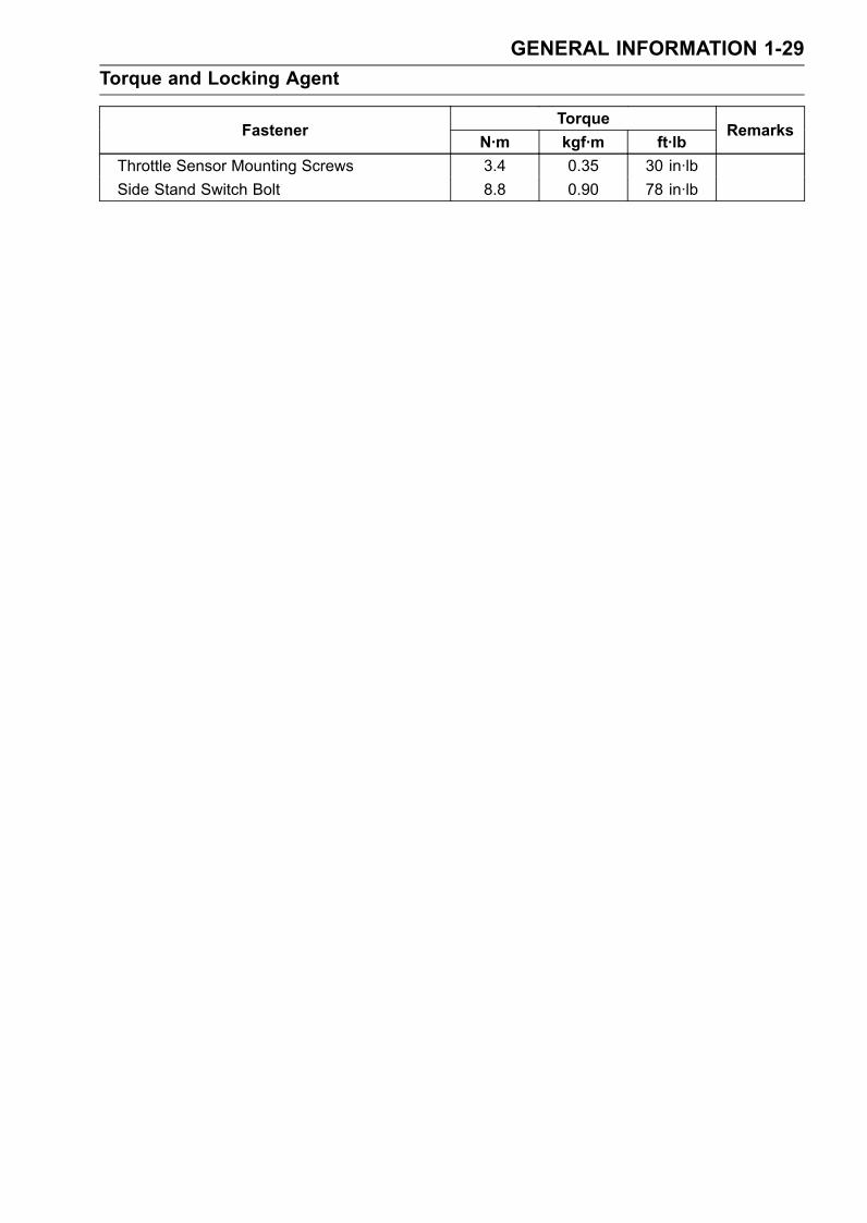
GENERAL INFORMATION 1-29Torque and Locking Agent
TorqueFastener
N·m kgf·m ft·lbRemarks
Throttle Sensor Mounting Screws 3.4 0.35 30 in·lbSide Stand Switch Bolt 8.8 0.90 78 in·lb
1-30 GENERAL INFORMATIONTorque and Locking Agent
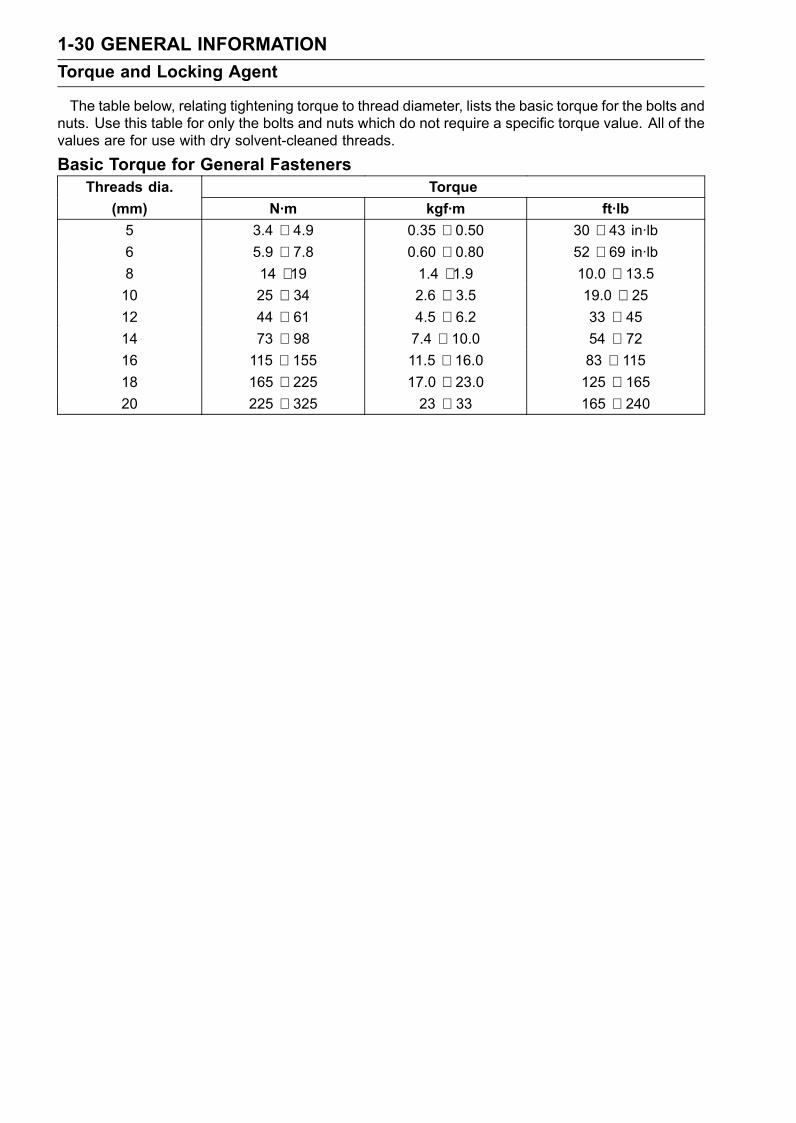
The table below, relating tightening torque to thread diameter, lists the basic torque for the bolts andnuts. Use this table for only the bolts and nuts which do not require a specific torque value. All of thevalues are for use with dry solvent-cleaned threads.
Basic Torque for General FastenersThreads dia. Torque
(mm) N·m kgf·m ft·lb5 3.4 ∼ 4.9 0.35 ∼ 0.50 30 ∼ 43 in·lb6 5.9 ∼ 7.8 0.60 ∼ 0.80 52 ∼ 69 in·lb8 14 ∼ 19 1.4 ∼ 1.9 10.0 ∼ 13.510 25 ∼ 34 2.6 ∼ 3.5 19.0 ∼ 2512 44 ∼ 61 4.5 ∼ 6.2 33 ∼ 4514 73 ∼ 98 7.4 ∼ 10.0 54 ∼ 7216 115 ∼ 155 11.5 ∼ 16.0 83 ∼ 11518 165 ∼ 225 17.0 ∼ 23.0 125 ∼ 16520 225 ∼ 325 23 ∼ 33 165 ∼ 240
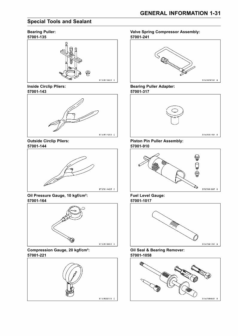
GENERAL INFORMATION 1-31Special Tools and Sealant
Bearing Puller:57001-135
Inside Circlip Pliers:57001-143
Outside Circlip Pliers:57001-144
Oil Pressure Gauge, 10 kgf/cm²:57001-164
Compression Gauge, 20 kgf/cm²:57001-221
Valve Spring Compressor Assembly:57001-241
Bearing Puller Adapter:57001-317
Piston Pin Puller Assembly:57001-910
Fuel Level Gauge:57001-1017
Oil Seal & Bearing Remover:57001-1058
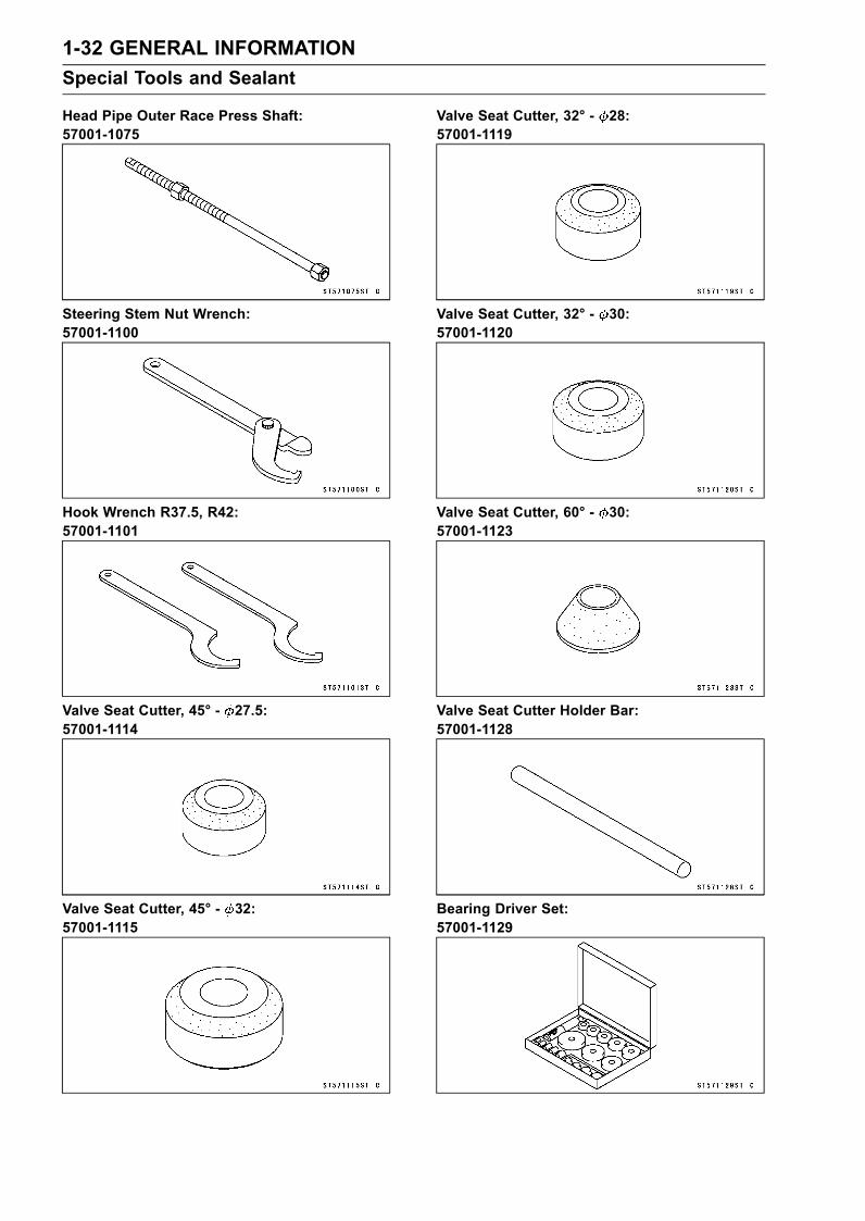
1-32 GENERAL INFORMATIONSpecial Tools and Sealant
Head Pipe Outer Race Press Shaft:57001-1075
Steering Stem Nut Wrench:57001-1100
Hook Wrench R37.5, R42:57001-1101
Valve Seat Cutter, 45° - 27.5:57001-1114
Valve Seat Cutter, 45° - 32:57001-1115
Valve Seat Cutter, 32° - 28:57001-1119
Valve Seat Cutter, 32° - 30:57001-1120
Valve Seat Cutter, 60° - 30:57001-1123
Valve Seat Cutter Holder Bar:57001-1128
Bearing Driver Set:57001-1129
GENERAL INFORMATION 1-33Special Tools and Sealant
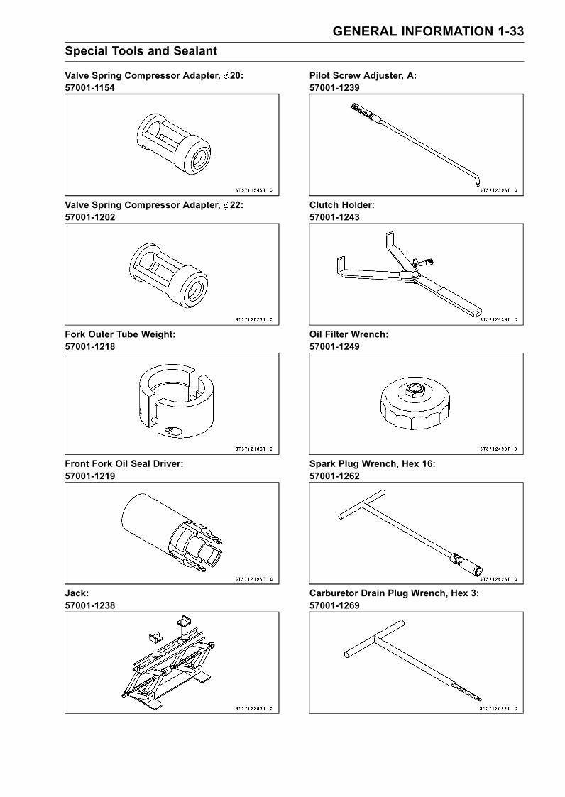
Valve Spring Compressor Adapter, 20:57001-1154
Valve Spring Compressor Adapter, 22:57001-1202
Fork Outer Tube Weight:57001-1218
Front Fork Oil Seal Driver:57001-1219
Jack:57001-1238
Pilot Screw Adjuster, A:57001-1239
Clutch Holder:57001-1243
Oil Filter Wrench:57001-1249
Spark Plug Wrench, Hex 16:57001-1262
Carburetor Drain Plug Wrench, Hex 3:57001-1269
1-34 GENERAL INFORMATIONSpecial Tools and Sealant
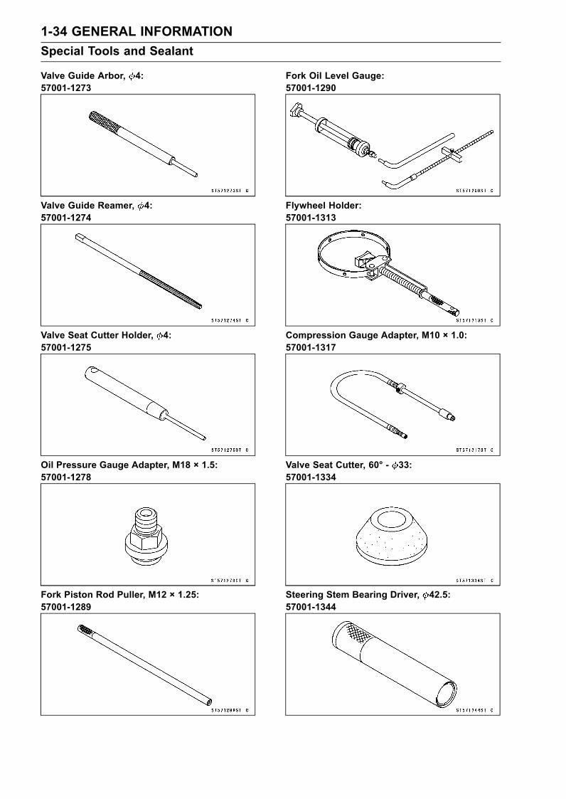
Valve Guide Arbor, 4:57001-1273
Valve Guide Reamer, 4:57001-1274
Valve Seat Cutter Holder, 4:57001-1275
Oil Pressure Gauge Adapter, M18 × 1.5:57001-1278
Fork Piston Rod Puller, M12 × 1.25:57001-1289
Fork Oil Level Gauge:57001-1290
Flywheel Holder:57001-1313
Compression Gauge Adapter, M10 × 1.0:57001-1317
Valve Seat Cutter, 60° - 33:57001-1334
Steering Stem Bearing Driver, 42.5:57001-1344
GENERAL INFORMATION 1-35Special Tools and Sealant
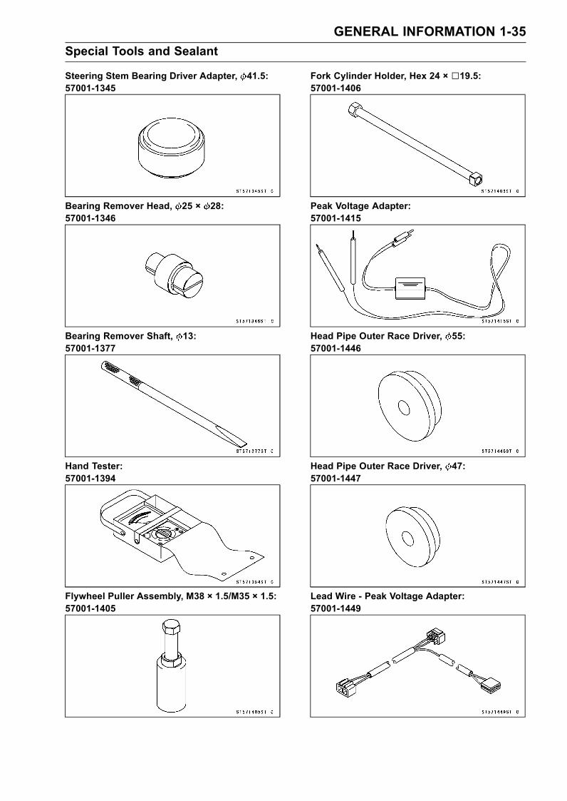
Steering Stem Bearing Driver Adapter, 41.5:57001-1345
Bearing Remover Head, 25 × 28:57001-1346
Bearing Remover Shaft, 13:57001-1377
Hand Tester:57001-1394
Flywheel Puller Assembly, M38 × 1.5/M35 × 1.5:57001-1405
Fork Cylinder Holder, Hex 24 × 19.5:57001-1406
Peak Voltage Adapter:57001-1415
Head Pipe Outer Race Driver, 55:57001-1446
Head Pipe Outer Race Driver, 47:57001-1447
Lead Wire - Peak Voltage Adapter:57001-1449
1-36 GENERAL INFORMATIONSpecial Tools and Sealant
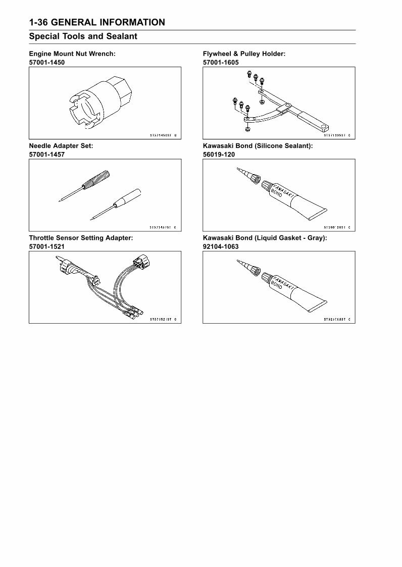
Engine Mount Nut Wrench:57001-1450
Needle Adapter Set:57001-1457
Throttle Sensor Setting Adapter:57001-1521
Flywheel & Pulley Holder:57001-1605
Kawasaki Bond (Silicone Sealant):56019-120
Kawasaki Bond (Liquid Gasket - Gray):92104-1063
GENERAL INFORMATION 1-37Cable, Wire, and Hose Routing
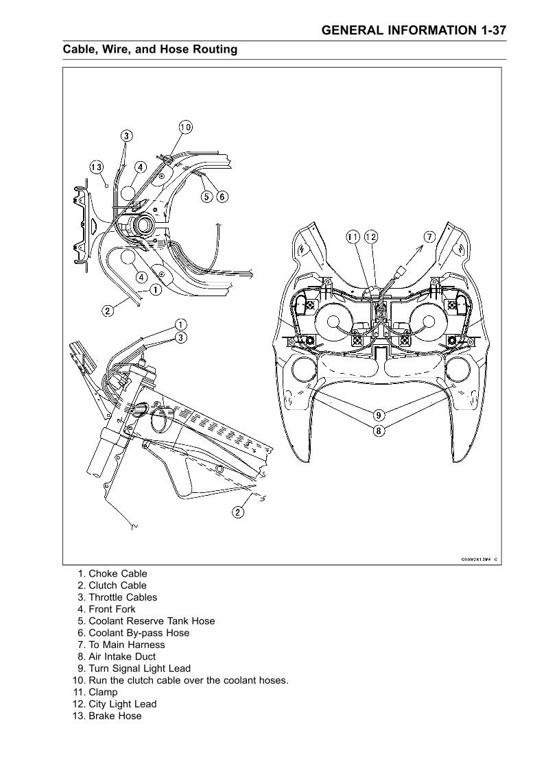
1. Choke Cable2. Clutch Cable3. Throttle Cables4. Front Fork5. Coolant Reserve Tank Hose6. Coolant By-pass Hose7. To Main Harness8. Air Intake Duct9. Turn Signal Light Lead10. Run the clutch cable over the coolant hoses.11. Clamp12. City Light Lead13. Brake Hose
1-38 GENERAL INFORMATIONCable, Wire, and Hose Routing
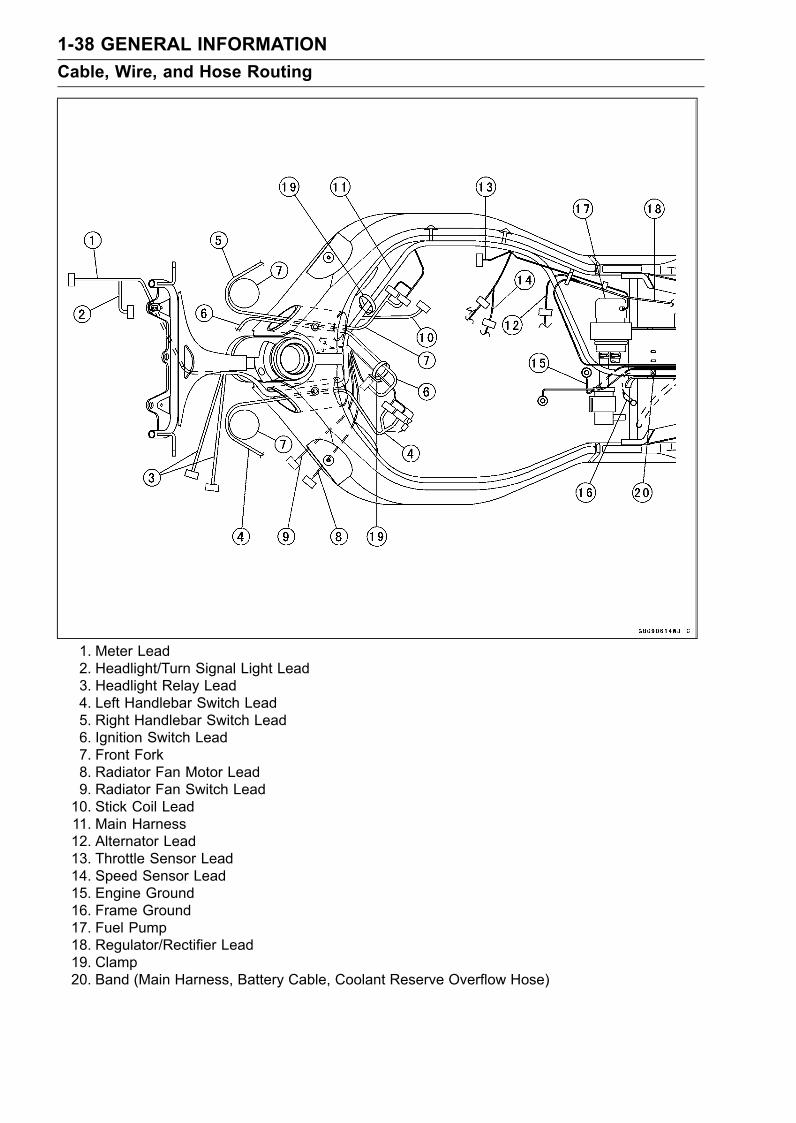
1. Meter Lead2. Headlight/Turn Signal Light Lead3. Headlight Relay Lead4. Left Handlebar Switch Lead5. Right Handlebar Switch Lead6. Ignition Switch Lead7. Front Fork8. Radiator Fan Motor Lead9. Radiator Fan Switch Lead10. Stick Coil Lead11. Main Harness12. Alternator Lead13. Throttle Sensor Lead14. Speed Sensor Lead15. Engine Ground16. Frame Ground17. Fuel Pump18. Regulator/Rectifier Lead19. Clamp20. Band (Main Harness, Battery Cable, Coolant Reserve Overflow Hose)
GENERAL INFORMATION 1-39Cable, Wire, and Hose Routing
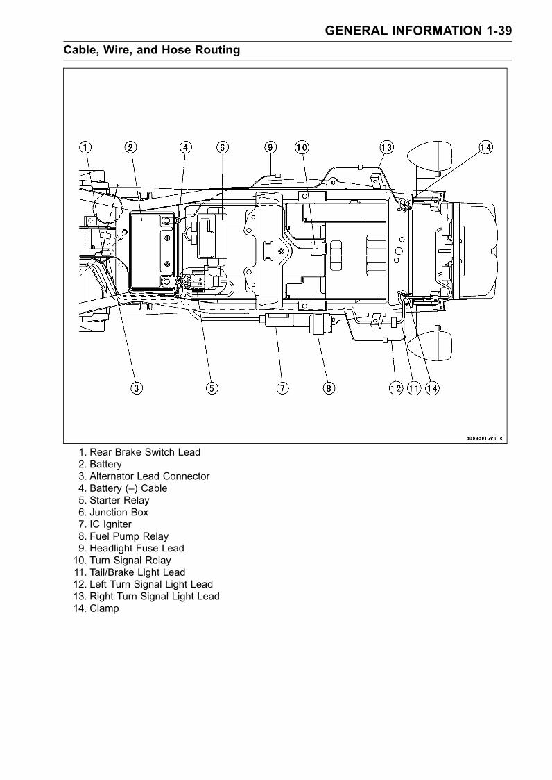
1. Rear Brake Switch Lead2. Battery3. Alternator Lead Connector4. Battery (–) Cable5. Starter Relay6. Junction Box7. IC Igniter8. Fuel Pump Relay9. Headlight Fuse Lead10. Turn Signal Relay11. Tail/Brake Light Lead12. Left Turn Signal Light Lead13. Right Turn Signal Light Lead14. Clamp
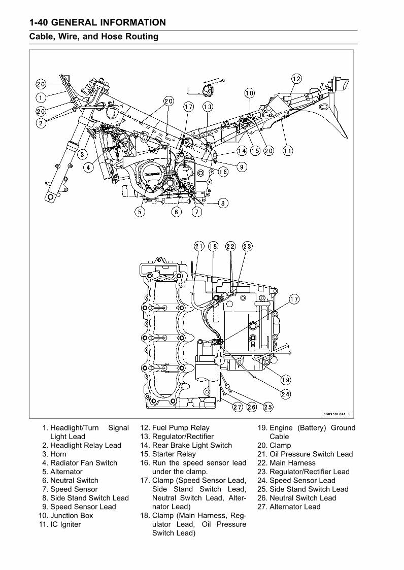
1-40 GENERAL INFORMATIONCable, Wire, and Hose Routing
1. Headlight/Turn SignalLight Lead
2. Headlight Relay Lead3. Horn4. Radiator Fan Switch5. Alternator6. Neutral Switch7. Speed Sensor8. Side Stand Switch Lead9. Speed Sensor Lead10. Junction Box11. IC Igniter
12. Fuel Pump Relay13. Regulator/Rectifier14. Rear Brake Light Switch15. Starter Relay16. Run the speed sensor lead
under the clamp.17. Clamp (Speed Sensor Lead,
Side Stand Switch Lead,Neutral Switch Lead, Alter-nator Lead)
18. Clamp (Main Harness, Reg-ulator Lead, Oil PressureSwitch Lead)
19. Engine (Battery) GroundCable
20. Clamp21. Oil Pressure Switch Lead22. Main Harness23. Regulator/Rectifier Lead24. Speed Sensor Lead25. Side Stand Switch Lead26. Neutral Switch Lead27. Alternator Lead
GENERAL INFORMATION 1-41Cable, Wire, and Hose Routing
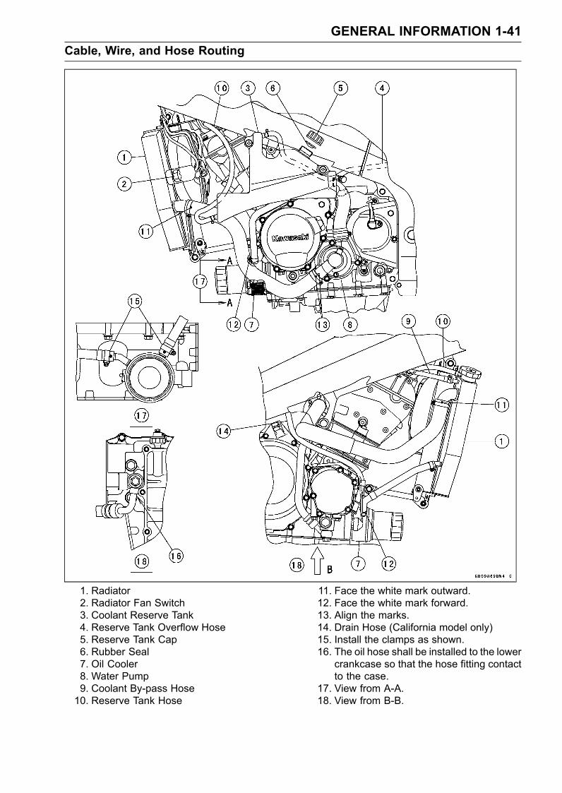
1. Radiator2. Radiator Fan Switch3. Coolant Reserve Tank4. Reserve Tank Overflow Hose5. Reserve Tank Cap6. Rubber Seal7. Oil Cooler8. Water Pump9. Coolant By-pass Hose10. Reserve Tank Hose
11. Face the white mark outward.12. Face the white mark forward.13. Align the marks.14. Drain Hose (California model only)15. Install the clamps as shown.16. The oil hose shall be installed to the lower
crankcase so that the hose fitting contactto the case.
17. View from A-A.18. View from B-B.
1-42 GENERAL INFORMATIONCable, Wire, and Hose Routing
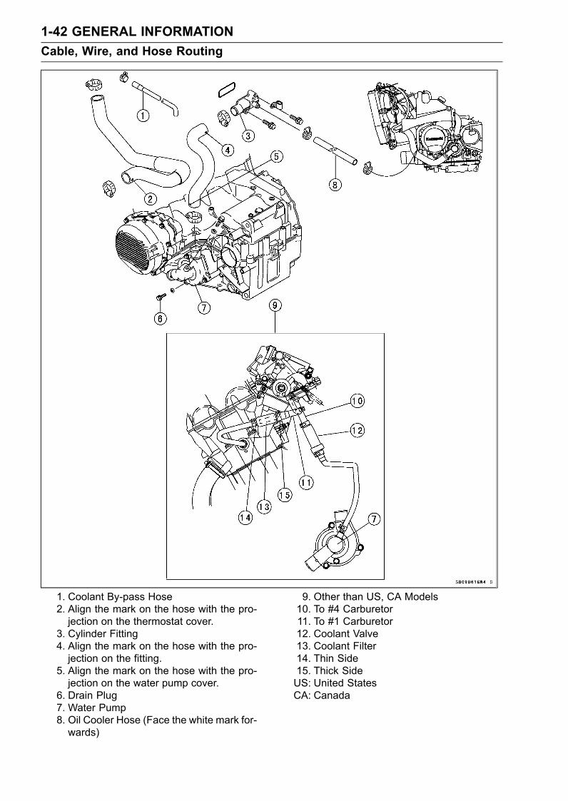
1. Coolant By-pass Hose2. Align the mark on the hose with the pro-jection on the thermostat cover.
3. Cylinder Fitting4. Align the mark on the hose with the pro-jection on the fitting.
5. Align the mark on the hose with the pro-jection on the water pump cover.
6. Drain Plug7. Water Pump8. Oil Cooler Hose (Face the white mark for-wards)
9. Other than US, CA Models10. To #4 Carburetor11. To #1 Carburetor12. Coolant Valve13. Coolant Filter14. Thin Side15. Thick SideUS: United StatesCA: Canada
GENERAL INFORMATION 1-43Cable, Wire, and Hose Routing
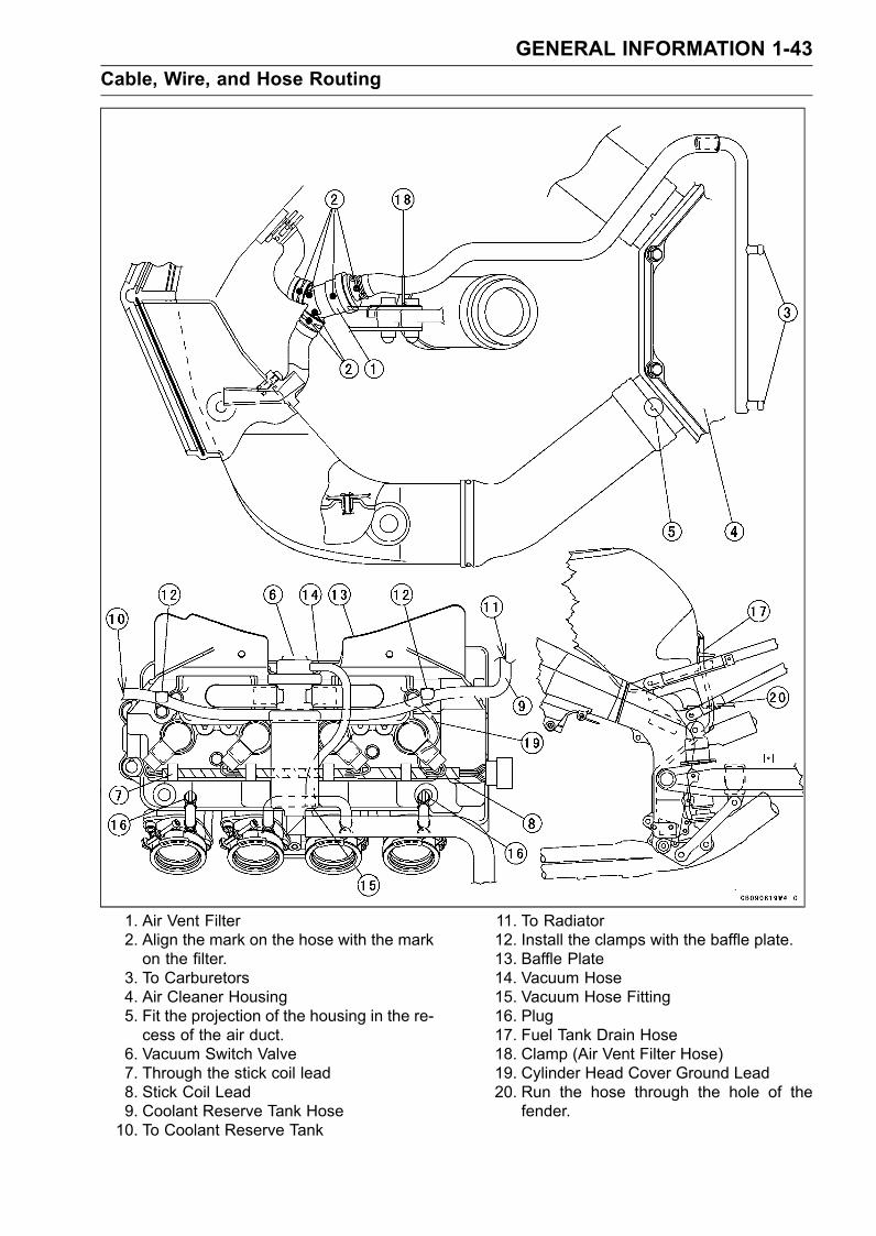
1. Air Vent Filter2. Align the mark on the hose with the markon the filter.
3. To Carburetors4. Air Cleaner Housing5. Fit the projection of the housing in the re-cess of the air duct.
6. Vacuum Switch Valve7. Through the stick coil lead8. Stick Coil Lead9. Coolant Reserve Tank Hose10. To Coolant Reserve Tank
11. To Radiator12. Install the clamps with the baffle plate.13. Baffle Plate14. Vacuum Hose15. Vacuum Hose Fitting16. Plug17. Fuel Tank Drain Hose18. Clamp (Air Vent Filter Hose)19. Cylinder Head Cover Ground Lead20. Run the hose through the hole of the
fender.
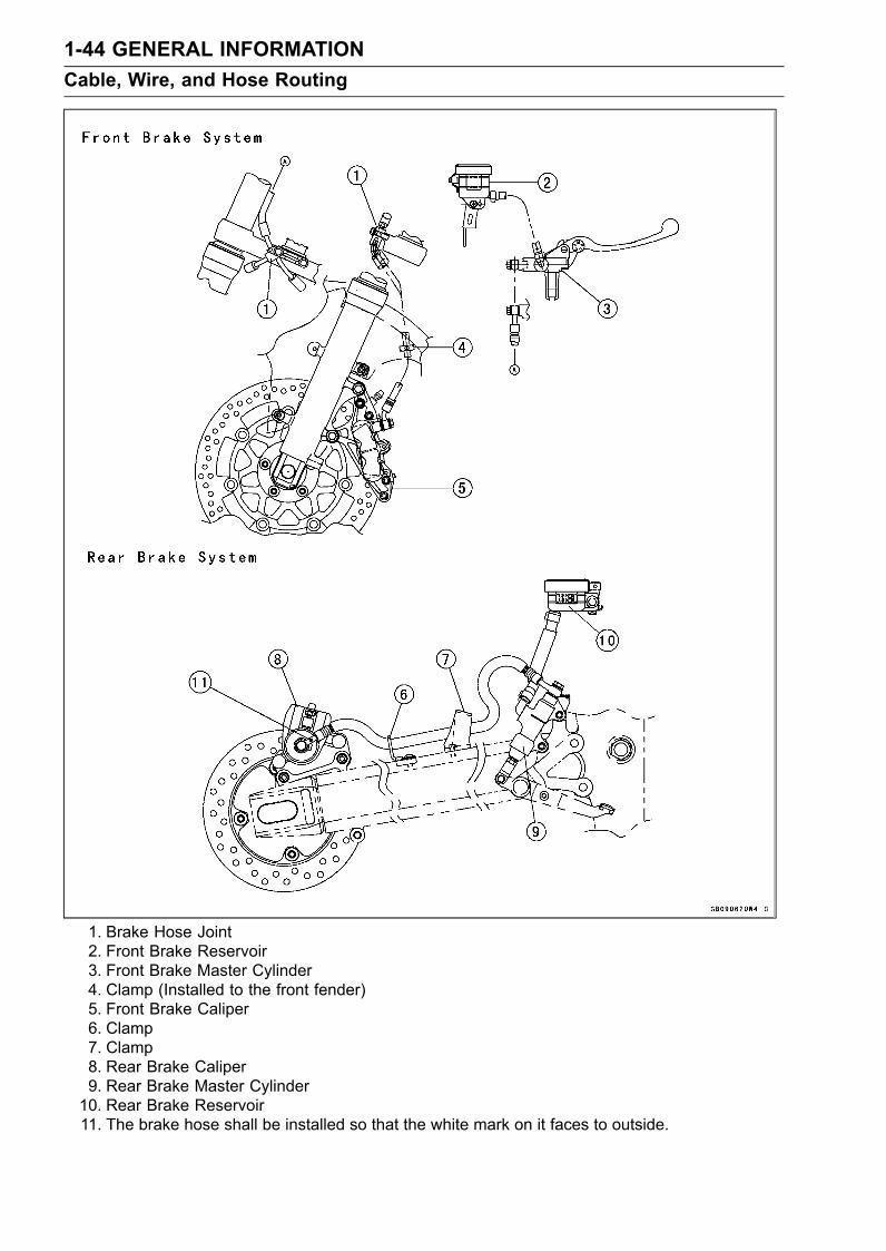
1-44 GENERAL INFORMATIONCable, Wire, and Hose Routing
1. Brake Hose Joint2. Front Brake Reservoir3. Front Brake Master Cylinder4. Clamp (Installed to the front fender)5. Front Brake Caliper6. Clamp7. Clamp8. Rear Brake Caliper9. Rear Brake Master Cylinder10. Rear Brake Reservoir11. The brake hose shall be installed so that the white mark on it faces to outside.
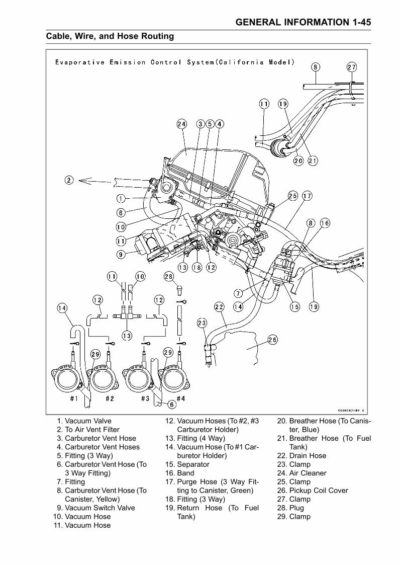
GENERAL INFORMATION 1-45Cable, Wire, and Hose Routing
1. Vacuum Valve2. To Air Vent Filter3. Carburetor Vent Hose4. Carburetor Vent Hoses5. Fitting (3 Way)6. Carburetor Vent Hose (To3 Way Fitting)
7. Fitting8. Carburetor Vent Hose (ToCanister, Yellow)
9. Vacuum Switch Valve10. Vacuum Hose11. Vacuum Hose
12. VacuumHoses (To #2, #3Carburetor Holder)
13. Fitting (4 Way)14. VacuumHose (To #1Car-
buretor Holder)15. Separator16. Band17. Purge Hose (3 Way Fit-
ting to Canister, Green)18. Fitting (3 Way)19. Return Hose (To Fuel
Tank)
20. Breather Hose (To Canis-ter, Blue)
21. Breather Hose (To FuelTank)
22. Drain Hose23. Clamp24. Air Cleaner25. Clamp26. Pickup Coil Cover27. Clamp28. Plug29. Clamp
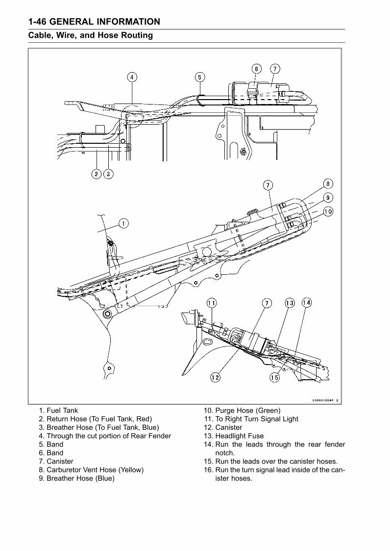
1-46 GENERAL INFORMATIONCable, Wire, and Hose Routing
1. Fuel Tank2. Return Hose (To Fuel Tank, Red)3. Breather Hose (To Fuel Tank, Blue)4. Through the cut portion of Rear Fender5. Band6. Band7. Canister8. Carburetor Vent Hose (Yellow)9. Breather Hose (Blue)
10. Purge Hose (Green)11. To Right Turn Signal Light12. Canister13. Headlight Fuse14. Run the leads through the rear fender
notch.15. Run the leads over the canister hoses.16. Run the turn signal lead inside of the can-
ister hoses.
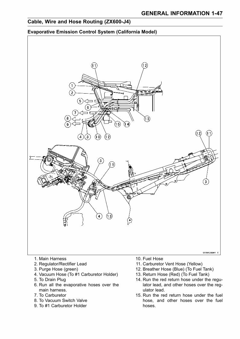
GENERAL INFORMATION 1-47Cable, Wire and Hose Routing (ZX600-J4)
Evaporative Emission Control System (California Model)
1. Main Harness2. Regulator/Rectifier Lead3. Purge Hose (green)4. Vacuum Hose (To #1 Carburetor Holder)5. To Drain Plug6. Run all the evaporative hoses over themain harness.
7. To Carburetor8. To Vacuum Switch Valve9. To #1 Carburetor Holder
10. Fuel Hose11. Carburetor Vent Hose (Yellow)12. Breather Hose (Blue) (To Fuel Tank)13. Return Hose (Red) (To Fuel Tank)14. Run the red return hose under the regu-
lator lead, and other hoses over the reg-ulator lead.
15. Run the red return hose under the fuelhose, and other hoses over the fuelhoses.

FUEL SYSTEM 2-1
2
Fuel System
Table of ContentsExploded View................................... 2-2Specifications .................................... 2-5Throttle Grip and Cables ................... 2-6
Throttle Grip Play Inspection........ 2-6Throttle Cable Installation ............ 2-6Throttle Cable Lubrication andInspection.................................. 2-6
Choke Cable...................................... 2-7Choke Cable Free PlayInspection.................................. 2-7
Choke Cable Free PlayAdjustment ................................ 2-7
Choke Cable Installation .............. 2-7Choke Cable Lubrication andInspection.................................. 2-7
Carburetors........................................ 2-8Idle Speed Inspection .................. 2-8Idle Speed Adjustment................. 2-8Synchronization Inspection .......... 2-8Synchronization Adjustment ........ 2-9Service Fuel Level Inspection ...... 2-9Service Fuel Level Adjustment .... 2-10Fuel System CleanlinessInspection.................................. 2-11
Carburetor Removal..................... 2-11Carburetor Installation.................. 2-12Carburetor Disassembly .............. 2-13Carburetor Assembly ................... 2-14Carburetor Separation ................. 2-14Carburetor Joining ....................... 2-14Carburetor Cleaning..................... 2-15Carburetor Inspection .................. 2-15Coolant Filter Cleaning (Otherthan United States and CanadaModels) ..................................... 2-17
Coolant Valve Inspection (Otherthan United States and CanadaModels) ..................................... 2-17
Air Cleaner......................................... 2-18Element Removal......................... 2-18Element Installation...................... 2-18Element Cleaning and Inspection 2-18Air Cleaner Housing Removal...... 2-19Air Cleaner Housing Installation... 2-19Air Vent Filter Cleaning ................ 2-19
Fuel Tank........................................... 2-20Fuel Tank Removal ...................... 2-20Fuel Tank Installation ................... 2-20Fuel Tank Inspection .................... 2-21Fuel Tank Cleaning ...................... 2-21Fuel Tap Removal ........................ 2-21Fuel Tap Installation ..................... 2-22Fuel Tap Inspection...................... 2-22
Fuel Pump, Fuel Filter ....................... 2-23Fuel Pump, Fuel Filter Removal .. 2-23Fuel Pump, Fuel Filter Installation 2-23Fuel Pump Inspection .................. 2-23Fuel Filter Inspection.................... 2-23
Evaporative Emission Control System(California Model Only) ................... 2-24Parts Removal/Installation ........... 2-24Hose Inspection ........................... 2-24Separator Inspection.................... 2-24Separator Operation Test............. 2-25Canister Inspection ...................... 2-25Vacuum Valve Inspection............. 2-26
2-2 FUEL SYSTEMExploded View
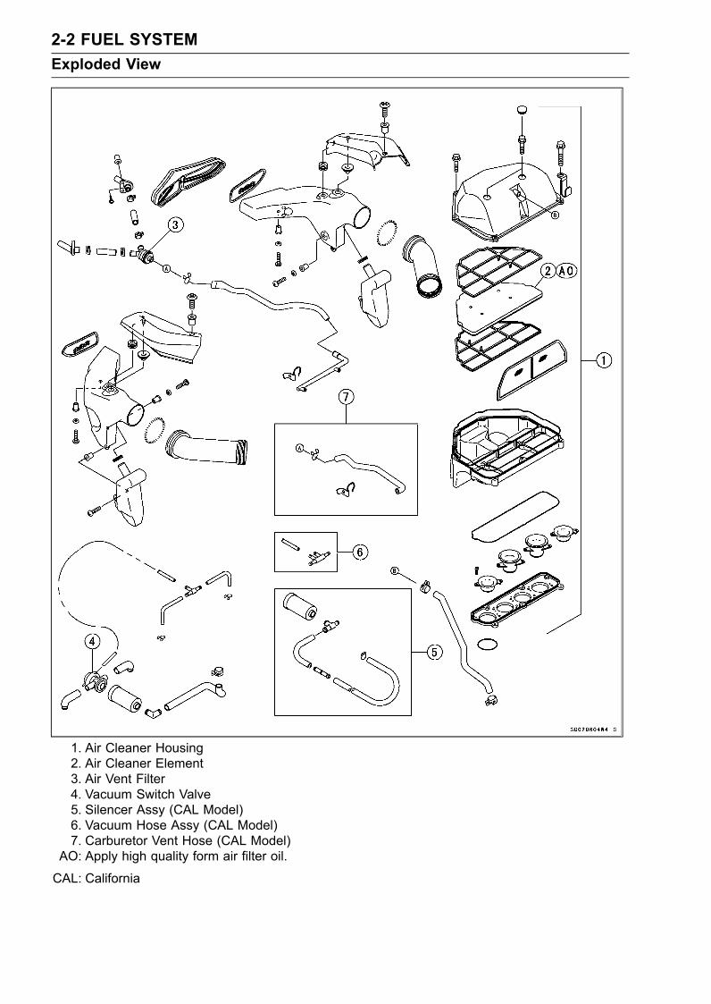
1. Air Cleaner Housing2. Air Cleaner Element3. Air Vent Filter4. Vacuum Switch Valve5. Silencer Assy (CAL Model)6. Vacuum Hose Assy (CAL Model)7. Carburetor Vent Hose (CAL Model)
AO: Apply high quality form air filter oil.
CAL: California
FUEL SYSTEM 2-3Exploded View
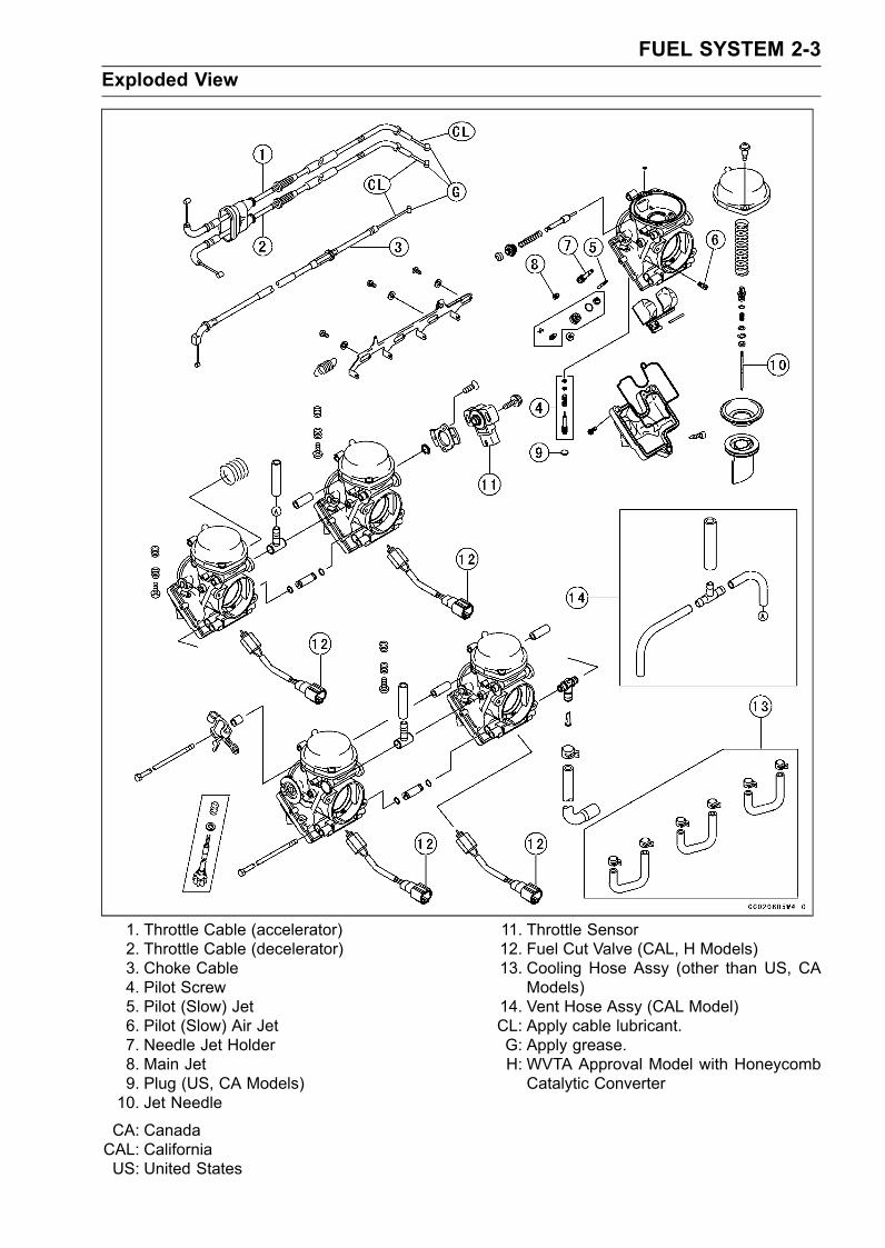
1. Throttle Cable (accelerator)2. Throttle Cable (decelerator)3. Choke Cable4. Pilot Screw5. Pilot (Slow) Jet6. Pilot (Slow) Air Jet7. Needle Jet Holder8. Main Jet9. Plug (US, CA Models)10. Jet Needle
11. Throttle Sensor12. Fuel Cut Valve (CAL, H Models)13. Cooling Hose Assy (other than US, CA
Models)14. Vent Hose Assy (CAL Model)CL: Apply cable lubricant.G: Apply grease.H: WVTA Approval Model with HoneycombCatalytic Converter
CA: CanadaCAL: CaliforniaUS: United States
2-4 FUEL SYSTEMExploded View
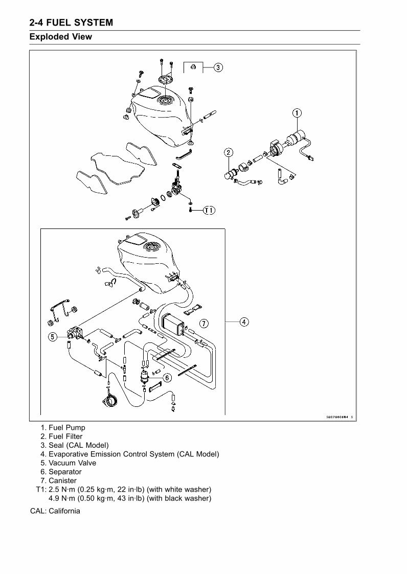
1. Fuel Pump2. Fuel Filter3. Seal (CAL Model)4. Evaporative Emission Control System (CAL Model)5. Vacuum Valve6. Separator7. CanisterT1: 2.5 N·m (0.25 kg·m, 22 in·lb) (with white washer)
4.9 N·m (0.50 kg·m, 43 in·lb) (with black washer)
CAL: California
FUEL SYSTEM 2-5Specifications
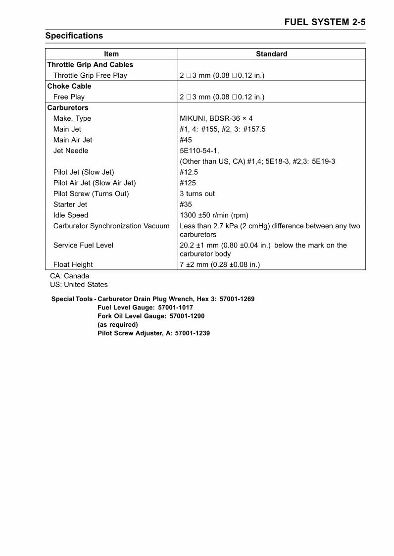
Item StandardThrottle Grip And CablesThrottle Grip Free Play 2 ∼ 3 mm (0.08 ∼ 0.12 in.)
Choke CableFree Play 2 ∼ 3 mm (0.08 ∼ 0.12 in.)
CarburetorsMake, Type MIKUNI, BDSR-36 × 4Main Jet #1, 4: #155, #2, 3: #157.5Main Air Jet #45Jet Needle 5E110-54-1,
(Other than US, CA) #1,4; 5E18-3, #2,3: 5E19-3Pilot Jet (Slow Jet) #12.5Pilot Air Jet (Slow Air Jet) #125Pilot Screw (Turns Out) 3 turns outStarter Jet #35Idle Speed 1300 ±50 r/min (rpm)Carburetor Synchronization Vacuum Less than 2.7 kPa (2 cmHg) difference between any two
carburetorsService Fuel Level 20.2 ±1 mm (0.80 ±0.04 in.) below the mark on the
carburetor bodyFloat Height 7 ±2 mm (0.28 ±0.08 in.)CA: CanadaUS: United States
Special Tools - Carburetor Drain Plug Wrench, Hex 3: 57001-1269Fuel Level Gauge: 57001-1017Fork Oil Level Gauge: 57001-1290(as required)Pilot Screw Adjuster, A: 57001-1239
2-6 FUEL SYSTEMThrottle Grip and Cables
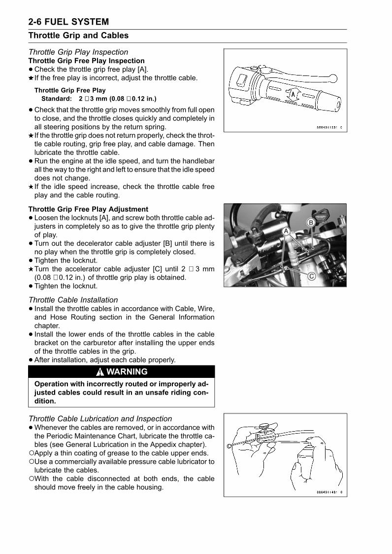
Throttle Grip Play InspectionThrottle Grip Free Play Inspection•Check the throttle grip free play [A].If the free play is incorrect, adjust the throttle cable.
Throttle Grip Free PlayStandard: 2 ∼ 3 mm (0.08 ∼ 0.12 in.)
•Check that the throttle grip moves smoothly from full opento close, and the throttle closes quickly and completely inall steering positions by the return spring.If the throttle grip does not return properly, check the throt-tle cable routing, grip free play, and cable damage. Thenlubricate the throttle cable.•Run the engine at the idle speed, and turn the handlebarall the way to the right and left to ensure that the idle speeddoes not change.If the idle speed increase, check the throttle cable freeplay and the cable routing.
Throttle Grip Free Play Adjustment• Loosen the locknuts [A], and screw both throttle cable ad-justers in completely so as to give the throttle grip plentyof play.• Turn out the decelerator cable adjuster [B] until there isno play when the throttle grip is completely closed.• Tighten the locknut.Turn the accelerator cable adjuster [C] until 2 ∼ 3 mm(0.08 ∼ 0.12 in.) of throttle grip play is obtained.• Tighten the locknut.Throttle Cable Installation• Install the throttle cables in accordance with Cable, Wire,and Hose Routing section in the General Informationchapter.• Install the lower ends of the throttle cables in the cablebracket on the carburetor after installing the upper endsof the throttle cables in the grip.• After installation, adjust each cable properly.
WARNINGOperation with incorrectly routed or improperly ad-justed cables could result in an unsafe riding con-dition.
Throttle Cable Lubrication and Inspection•Whenever the cables are removed, or in accordance withthe Periodic Maintenance Chart, lubricate the throttle ca-bles (see General Lubrication in the Appedix chapter).Apply a thin coating of grease to the cable upper ends.Use a commercially available pressure cable lubricator tolubricate the cables.With the cable disconnected at both ends, the cableshould move freely in the cable housing.
FUEL SYSTEM 2-7Choke Cable
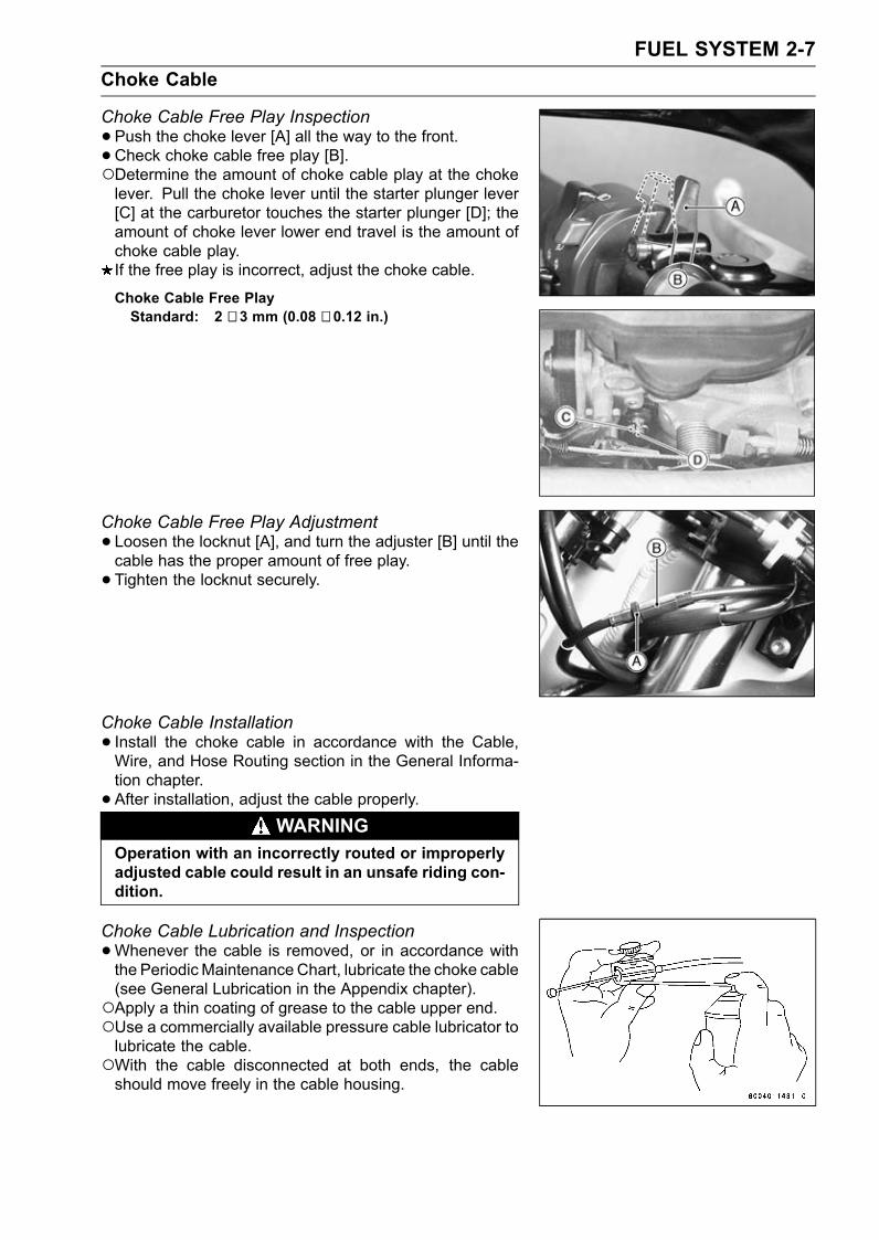
Choke Cable Free Play Inspection•Push the choke lever [A] all the way to the front.• Check choke cable free play [B].Determine the amount of choke cable play at the chokelever. Pull the choke lever until the starter plunger lever[C] at the carburetor touches the starter plunger [D]; theamount of choke lever lower end travel is the amount ofchoke cable play.If the free play is incorrect, adjust the choke cable.
Choke Cable Free PlayStandard: 2 ∼ 3 mm (0.08 ∼ 0.12 in.)
Choke Cable Free Play Adjustment• Loosen the locknut [A], and turn the adjuster [B] until thecable has the proper amount of free play.• Tighten the locknut securely.
Choke Cable Installation• Install the choke cable in accordance with the Cable,Wire, and Hose Routing section in the General Informa-tion chapter.• After installation, adjust the cable properly.
WARNINGOperation with an incorrectly routed or improperlyadjusted cable could result in an unsafe riding con-dition.
Choke Cable Lubrication and Inspection•Whenever the cable is removed, or in accordance withthe PeriodicMaintenanceChart, lubricate the choke cable(see General Lubrication in the Appendix chapter).Apply a thin coating of grease to the cable upper end.Use a commercially available pressure cable lubricator tolubricate the cable.With the cable disconnected at both ends, the cableshould move freely in the cable housing.
2-8 FUEL SYSTEMCarburetors
Idle Speed Inspection•Start the engine and warm it up thoroughly.•With the engine idling, turn the handlebar to both sides.If handlebar movement changes the idle speed, thethrottle cables may be improperly adjusted or incorrectlyrouted, or damaged. Be sure to correct any of theseconditions before riding (see Cable, Wire, and HoseRouting section in the General Information chapter).
WARNINGOperation with improperly adjusted, incorrectlyrouted, or damaged cables could result in an un-safe riding condition.
•Check idle speed.If the idle speed is out of the specified range, adjust it.
Idle SpeedStandard: 1 300 ±50 r/min (rpm)
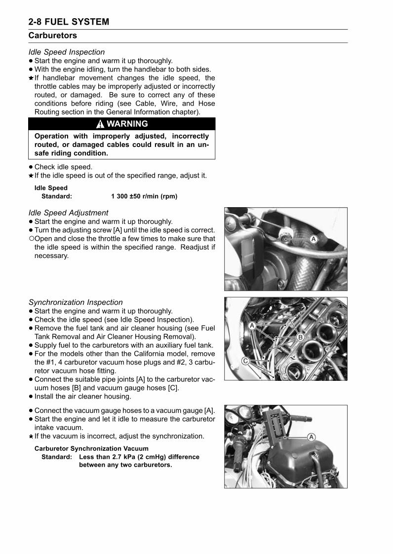
Idle Speed Adjustment•Start the engine and warm it up thoroughly.• Turn the adjusting screw [A] until the idle speed is correct.Open and close the throttle a few times to make sure thatthe idle speed is within the specified range. Readjust ifnecessary.
Synchronization Inspection•Start the engine and warm it up thoroughly.•Check the idle speed (see Idle Speed Inspection).• Remove the fuel tank and air cleaner housing (see FuelTank Removal and Air Cleaner Housing Removal).• Supply fuel to the carburetors with an auxiliary fuel tank.• For the models other than the California model, removethe #1, 4 carburetor vacuum hose plugs and #2, 3 carbu-retor vacuum hose fitting.•Connect the suitable pipe joints [A] to the carburetor vac-uum hoses [B] and vacuum gauge hoses [C].• Install the air cleaner housing.•Connect the vacuum gauge hoses to a vacuum gauge [A].• Start the engine and let it idle to measure the carburetorintake vacuum.If the vacuum is incorrect, adjust the synchronization.
Carburetor Synchronization VacuumStandard: Less than 2.7 kPa (2 cmHg) difference
between any two carburetors.
FUEL SYSTEM 2-9Carburetors
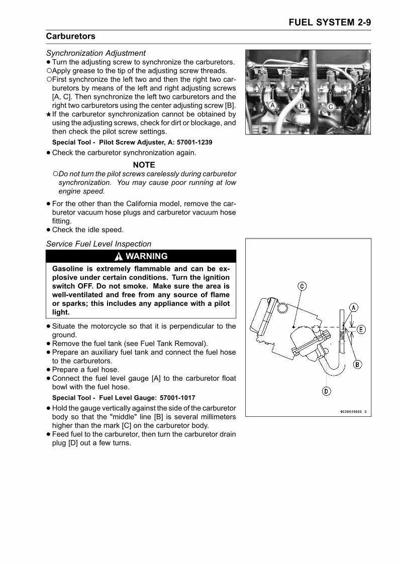
Synchronization Adjustment•Turn the adjusting screw to synchronize the carburetors.Apply grease to the tip of the adjusting screw threads.First synchronize the left two and then the right two car-buretors by means of the left and right adjusting screws[A, C]. Then synchronize the left two carburetors and theright two carburetors using the center adjusting screw [B].If the carburetor synchronization cannot be obtained byusing the adjusting screws, check for dirt or blockage, andthen check the pilot screw settings.Special Tool - Pilot Screw Adjuster, A: 57001-1239
•Check the carburetor synchronization again.NOTE
Do not turn the pilot screws carelessly during carburetorsynchronization. You may cause poor running at lowengine speed.
•For the other than the California model, remove the car-buretor vacuum hose plugs and carburetor vacuum hosefitting.•Check the idle speed.Service Fuel Level Inspection
WARNINGGasoline is extremely flammable and can be ex-plosive under certain conditions. Turn the ignitionswitch OFF. Do not smoke. Make sure the area iswell-ventilated and free from any source of flameor sparks; this includes any appliance with a pilotlight.
•Situate the motorcycle so that it is perpendicular to theground.•Remove the fuel tank (see Fuel Tank Removal).• Prepare an auxiliary fuel tank and connect the fuel hoseto the carburetors.• Prepare a fuel hose.•Connect the fuel level gauge [A] to the carburetor floatbowl with the fuel hose.Special Tool - Fuel Level Gauge: 57001-1017
•Hold the gauge vertically against the side of the carburetorbody so that the "middle" line [B] is several millimetershigher than the mark [C] on the carburetor body.• Feed fuel to the carburetor, then turn the carburetor drainplug [D] out a few turns.
2-10 FUEL SYSTEMCarburetors
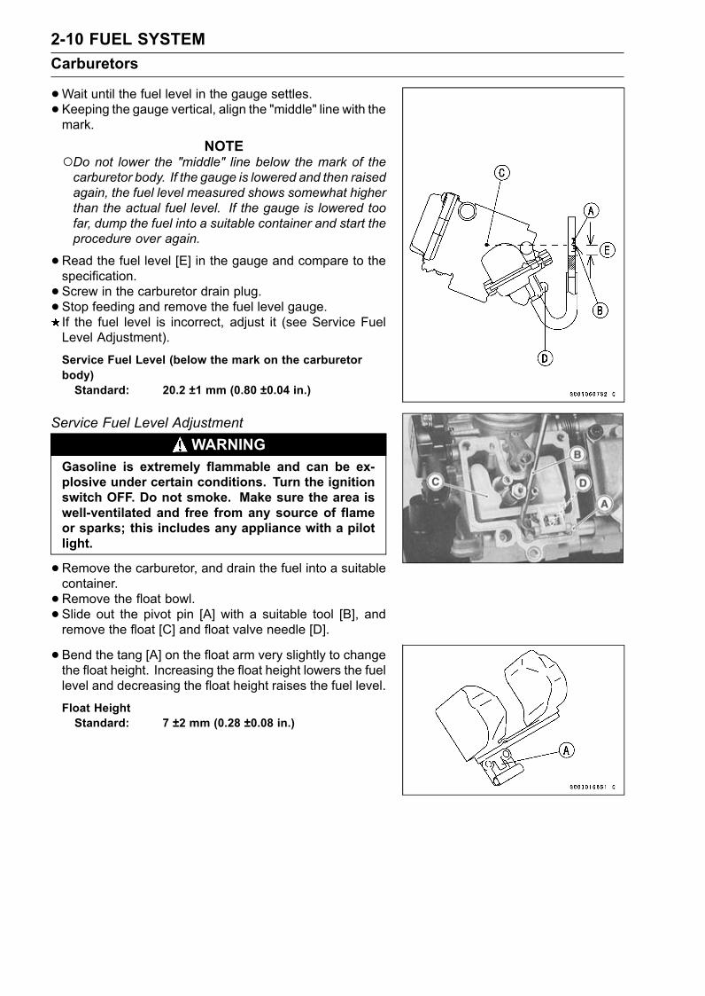
•Wait until the fuel level in the gauge settles.• Keeping the gauge vertical, align the "middle" line with themark.
NOTEDo not lower the "middle" line below the mark of thecarburetor body. If the gauge is lowered and then raisedagain, the fuel level measured shows somewhat higherthan the actual fuel level. If the gauge is lowered toofar, dump the fuel into a suitable container and start theprocedure over again.
•Read the fuel level [E] in the gauge and compare to thespecification.• Screw in the carburetor drain plug.• Stop feeding and remove the fuel level gauge.If the fuel level is incorrect, adjust it (see Service FuelLevel Adjustment).
Service Fuel Level (below the mark on the carburetorbody)Standard: 20.2 ±1 mm (0.80 ±0.04 in.)
Service Fuel Level AdjustmentWARNING
Gasoline is extremely flammable and can be ex-plosive under certain conditions. Turn the ignitionswitch OFF. Do not smoke. Make sure the area iswell-ventilated and free from any source of flameor sparks; this includes any appliance with a pilotlight.
•Remove the carburetor, and drain the fuel into a suitablecontainer.• Remove the float bowl.• Slide out the pivot pin [A] with a suitable tool [B], andremove the float [C] and float valve needle [D].
• Bend the tang [A] on the float arm very slightly to changethe float height. Increasing the float height lowers the fuellevel and decreasing the float height raises the fuel level.
Float HeightStandard: 7 ±2 mm (0.28 ±0.08 in.)
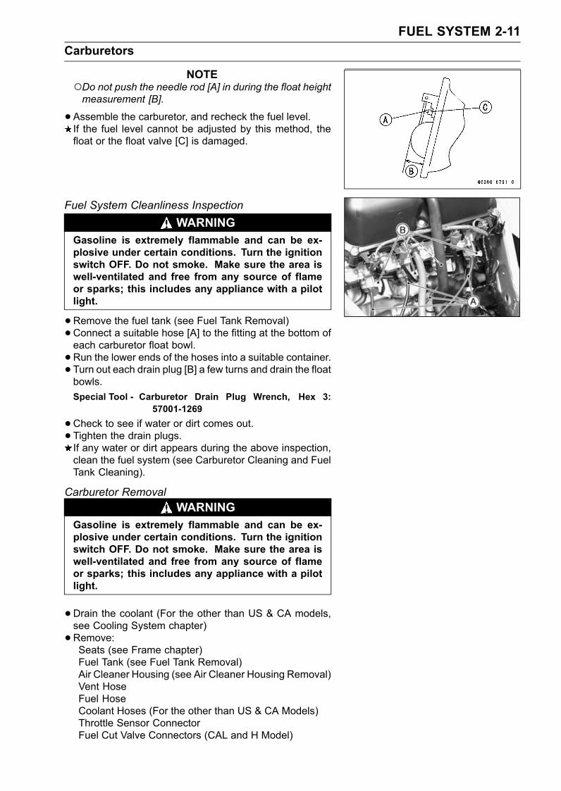
FUEL SYSTEM 2-11Carburetors
NOTEDo not push the needle rod [A] in during the float heightmeasurement [B].
•Assemble the carburetor, and recheck the fuel level.If the fuel level cannot be adjusted by this method, thefloat or the float valve [C] is damaged.
Fuel System Cleanliness InspectionWARNING
Gasoline is extremely flammable and can be ex-plosive under certain conditions. Turn the ignitionswitch OFF. Do not smoke. Make sure the area iswell-ventilated and free from any source of flameor sparks; this includes any appliance with a pilotlight.
•Remove the fuel tank (see Fuel Tank Removal)•Connect a suitable hose [A] to the fitting at the bottom ofeach carburetor float bowl.• Run the lower ends of the hoses into a suitable container.• Turn out each drain plug [B] a few turns and drain the floatbowls.Special Tool - Carburetor Drain Plug Wrench, Hex 3:
57001-1269
•Check to see if water or dirt comes out.• Tighten the drain plugs.If any water or dirt appears during the above inspection,clean the fuel system (see Carburetor Cleaning and FuelTank Cleaning).
Carburetor RemovalWARNING
Gasoline is extremely flammable and can be ex-plosive under certain conditions. Turn the ignitionswitch OFF. Do not smoke. Make sure the area iswell-ventilated and free from any source of flameor sparks; this includes any appliance with a pilotlight.
•Drain the coolant (For the other than US & CA models,see Cooling System chapter)•Remove:Seats (see Frame chapter)Fuel Tank (see Fuel Tank Removal)Air Cleaner Housing (see Air Cleaner Housing Removal)Vent HoseFuel HoseCoolant Hoses (For the other than US & CA Models)Throttle Sensor ConnectorFuel Cut Valve Connectors (CAL and H Model)
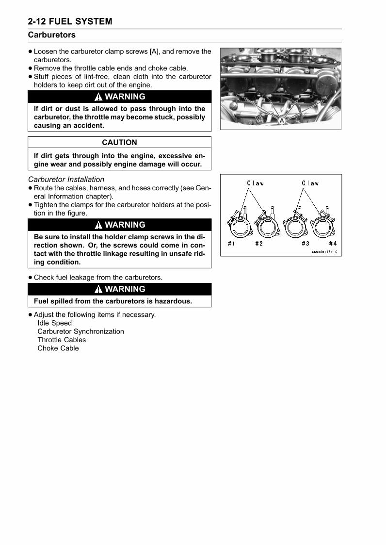
2-12 FUEL SYSTEMCarburetors
• Loosen the carburetor clamp screws [A], and remove thecarburetors.•Remove the throttle cable ends and choke cable.• Stuff pieces of lint-free, clean cloth into the carburetorholders to keep dirt out of the engine.
WARNINGIf dirt or dust is allowed to pass through into thecarburetor, the throttle may become stuck, possiblycausing an accident.
CAUTIONIf dirt gets through into the engine, excessive en-gine wear and possibly engine damage will occur.
Carburetor Installation•Route the cables, harness, and hoses correctly (see Gen-eral Information chapter).• Tighten the clamps for the carburetor holders at the posi-tion in the figure.
WARNINGBe sure to install the holder clamp screws in the di-rection shown. Or, the screws could come in con-tact with the throttle linkage resulting in unsafe rid-ing condition.
•Check fuel leakage from the carburetors.
WARNINGFuel spilled from the carburetors is hazardous.
•Adjust the following items if necessary.Idle SpeedCarburetor SynchronizationThrottle CablesChoke Cable
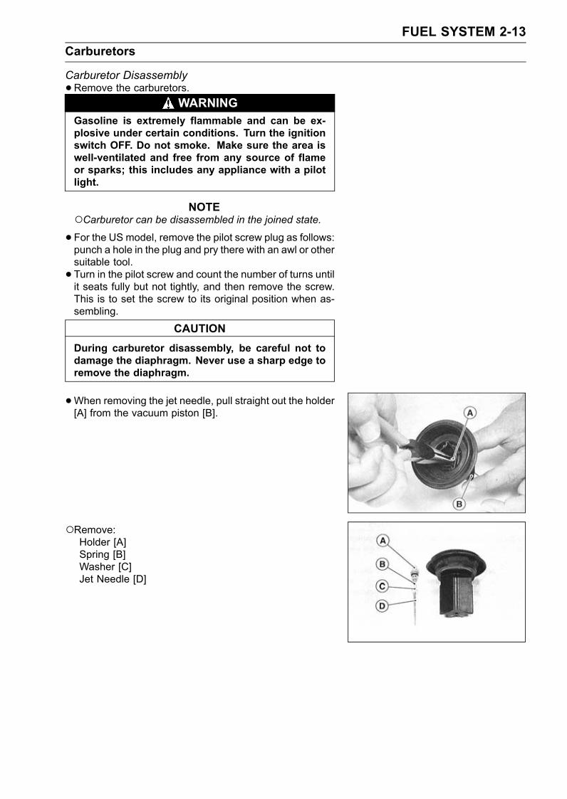
FUEL SYSTEM 2-13Carburetors
Carburetor Disassembly•Remove the carburetors.
WARNINGGasoline is extremely flammable and can be ex-plosive under certain conditions. Turn the ignitionswitch OFF. Do not smoke. Make sure the area iswell-ventilated and free from any source of flameor sparks; this includes any appliance with a pilotlight.
NOTECarburetor can be disassembled in the joined state.•For the US model, remove the pilot screw plug as follows:punch a hole in the plug and pry there with an awl or othersuitable tool.• Turn in the pilot screw and count the number of turns untilit seats fully but not tightly, and then remove the screw.This is to set the screw to its original position when as-sembling.
CAUTIONDuring carburetor disassembly, be careful not todamage the diaphragm. Never use a sharp edge toremove the diaphragm.
•When removing the jet needle, pull straight out the holder[A] from the vacuum piston [B].
Remove:Holder [A]Spring [B]Washer [C]Jet Needle [D]
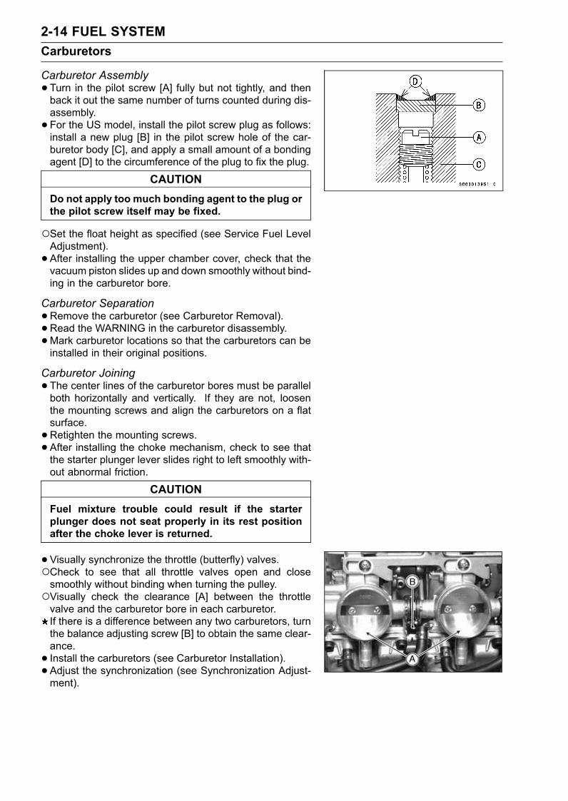
2-14 FUEL SYSTEMCarburetors
Carburetor Assembly•Turn in the pilot screw [A] fully but not tightly, and thenback it out the same number of turns counted during dis-assembly.• For the US model, install the pilot screw plug as follows:install a new plug [B] in the pilot screw hole of the car-buretor body [C], and apply a small amount of a bondingagent [D] to the circumference of the plug to fix the plug.
CAUTIONDo not apply too much bonding agent to the plug orthe pilot screw itself may be fixed.
Set the float height as specified (see Service Fuel LevelAdjustment).• After installing the upper chamber cover, check that thevacuum piston slides up and down smoothly without bind-ing in the carburetor bore.
Carburetor Separation•Remove the carburetor (see Carburetor Removal).• Read the WARNING in the carburetor disassembly.•Mark carburetor locations so that the carburetors can beinstalled in their original positions.
Carburetor Joining•The center lines of the carburetor bores must be parallelboth horizontally and vertically. If they are not, loosenthe mounting screws and align the carburetors on a flatsurface.•Retighten the mounting screws.• After installing the choke mechanism, check to see thatthe starter plunger lever slides right to left smoothly with-out abnormal friction.
CAUTIONFuel mixture trouble could result if the starterplunger does not seat properly in its rest positionafter the choke lever is returned.
•Visually synchronize the throttle (butterfly) valves.Check to see that all throttle valves open and closesmoothly without binding when turning the pulley.Visually check the clearance [A] between the throttlevalve and the carburetor bore in each carburetor.If there is a difference between any two carburetors, turnthe balance adjusting screw [B] to obtain the same clear-ance.• Install the carburetors (see Carburetor Installation).• Adjust the synchronization (see Synchronization Adjust-ment).
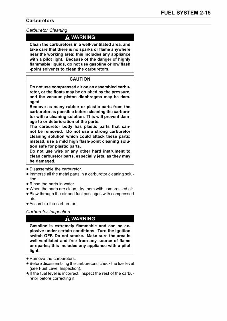
FUEL SYSTEM 2-15Carburetors
Carburetor CleaningWARNING
Clean the carburetors in a well-ventilated area, andtake care that there is no sparks or flame anywherenear the working area; this includes any appliancewith a pilot light. Because of the danger of highlyflammable liquids, do not use gasoline or low flash-point solvents to clean the carburetors.
CAUTIONDo not use compressed air on an assembled carbu-retor, or the floats may be crushed by the pressure,and the vacuum piston diaphragms may be dam-aged.Remove as many rubber or plastic parts from thecarburetor as possible before cleaning the carbure-tor with a cleaning solution. This will prevent dam-age to or deterioration of the parts.The carburetor body has plastic parts that can-not be removed. Do not use a strong carburetorcleaning solution which could attack these parts;instead, use a mild high flash-point cleaning solu-tion safe for plastic parts.Do not use wire or any other hard instrument toclean carburetor parts, especially jets, as they maybe damaged.
•Disassemble the carburetor.• Immerse all the metal parts in a carburetor cleaning solu-tion.•Rinse the parts in water.•When the parts are clean, dry them with compressed air.• Blow through the air and fuel passages with compressedair.• Assemble the carburetor.Carburetor Inspection
WARNINGGasoline is extremely flammable and can be ex-plosive under certain conditions. Turn the ignitionswitch OFF. Do not smoke. Make sure the area iswell-ventilated and free from any source of flameor sparks; this includes any appliance with a pilotlight.
•Remove the carburetors.• Before disassembling the carburetors, check the fuel level(see Fuel Level Inspection).If the fuel level is incorrect, inspect the rest of the carbu-retor before correcting it.
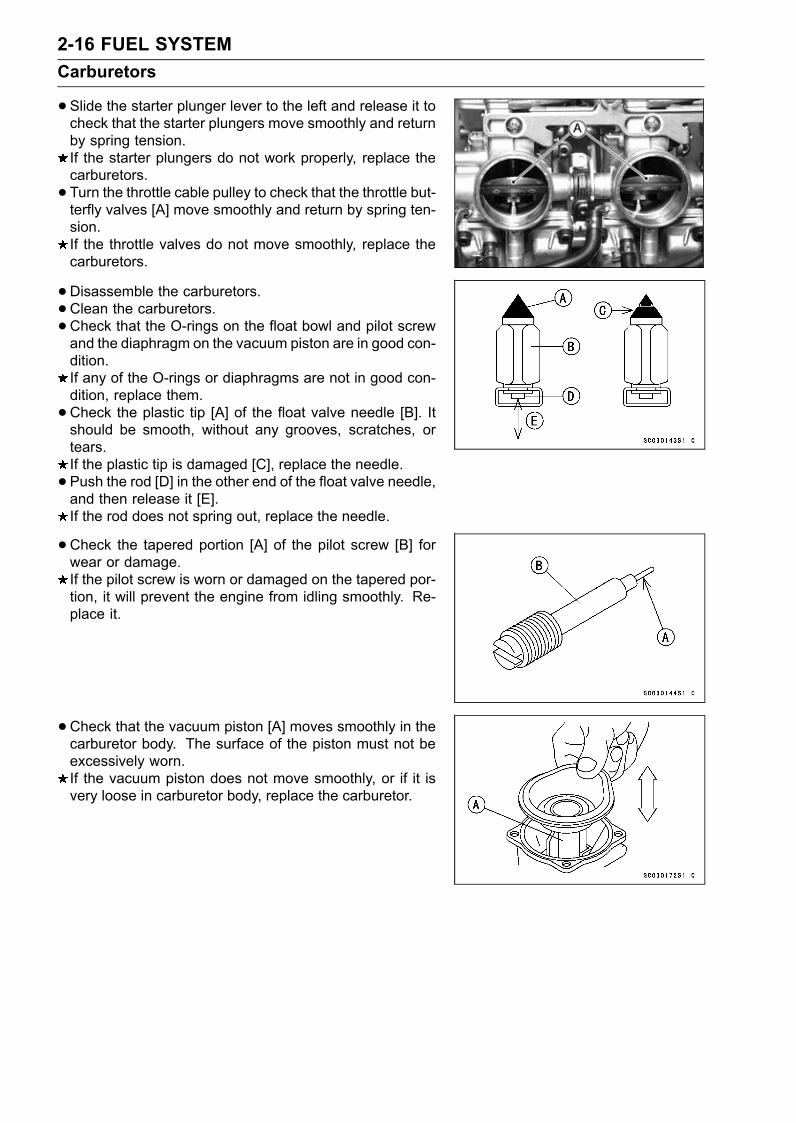
2-16 FUEL SYSTEMCarburetors
•Slide the starter plunger lever to the left and release it tocheck that the starter plungers move smoothly and returnby spring tension.If the starter plungers do not work properly, replace thecarburetors.• Turn the throttle cable pulley to check that the throttle but-terfly valves [A] move smoothly and return by spring ten-sion.If the throttle valves do not move smoothly, replace thecarburetors.
•Disassemble the carburetors.•Clean the carburetors.•Check that the O-rings on the float bowl and pilot screwand the diaphragm on the vacuum piston are in good con-dition.If any of the O-rings or diaphragms are not in good con-dition, replace them.•Check the plastic tip [A] of the float valve needle [B]. Itshould be smooth, without any grooves, scratches, ortears.If the plastic tip is damaged [C], replace the needle.• Push the rod [D] in the other end of the float valve needle,and then release it [E].If the rod does not spring out, replace the needle.
•Check the tapered portion [A] of the pilot screw [B] forwear or damage.If the pilot screw is worn or damaged on the tapered por-tion, it will prevent the engine from idling smoothly. Re-place it.
• Check that the vacuum piston [A] moves smoothly in thecarburetor body. The surface of the piston must not beexcessively worn.If the vacuum piston does not move smoothly, or if it isvery loose in carburetor body, replace the carburetor.
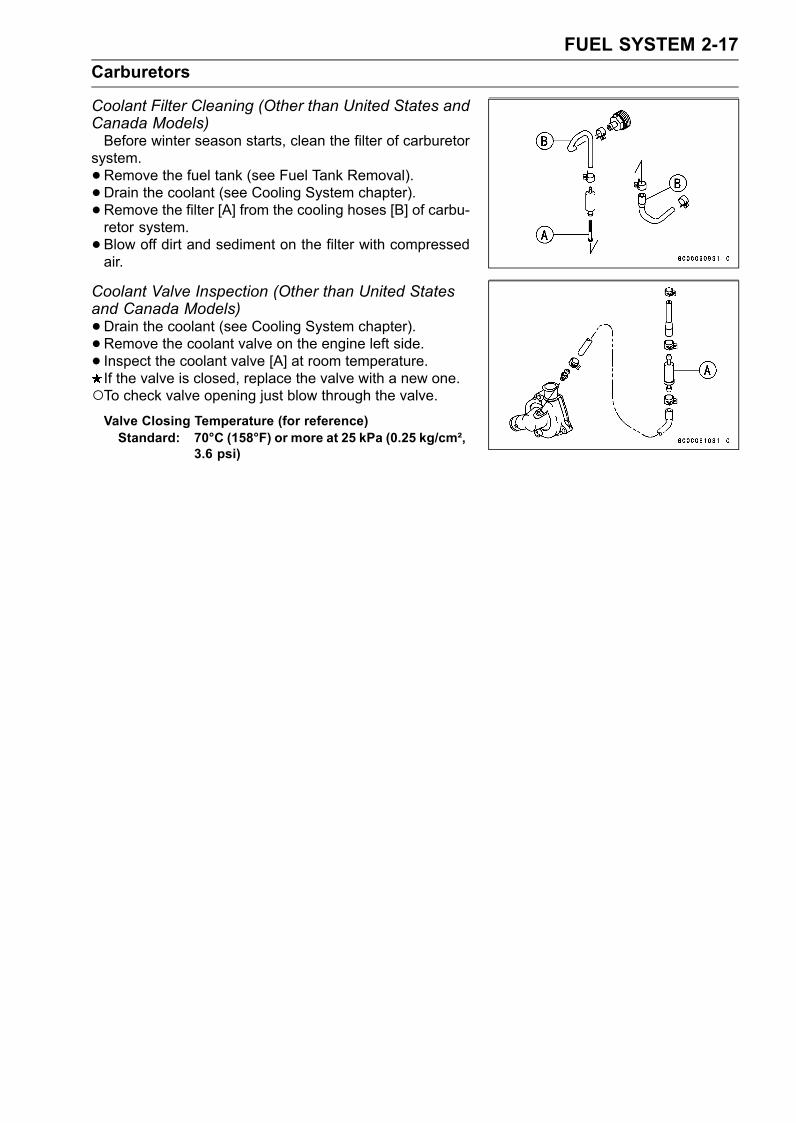
FUEL SYSTEM 2-17Carburetors
Coolant Filter Cleaning (Other than United States andCanada Models)Before winter season starts, clean the filter of carburetor
system.•Remove the fuel tank (see Fuel Tank Removal).• Drain the coolant (see Cooling System chapter).• Remove the filter [A] from the cooling hoses [B] of carbu-retor system.• Blow off dirt and sediment on the filter with compressedair.
Coolant Valve Inspection (Other than United Statesand Canada Models)•Drain the coolant (see Cooling System chapter).• Remove the coolant valve on the engine left side.• Inspect the coolant valve [A] at room temperature.If the valve is closed, replace the valve with a new one.To check valve opening just blow through the valve.Valve Closing Temperature (for reference)Standard: 70°C (158°F) or more at 25 kPa (0.25 kg/cm²,
3.6 psi)
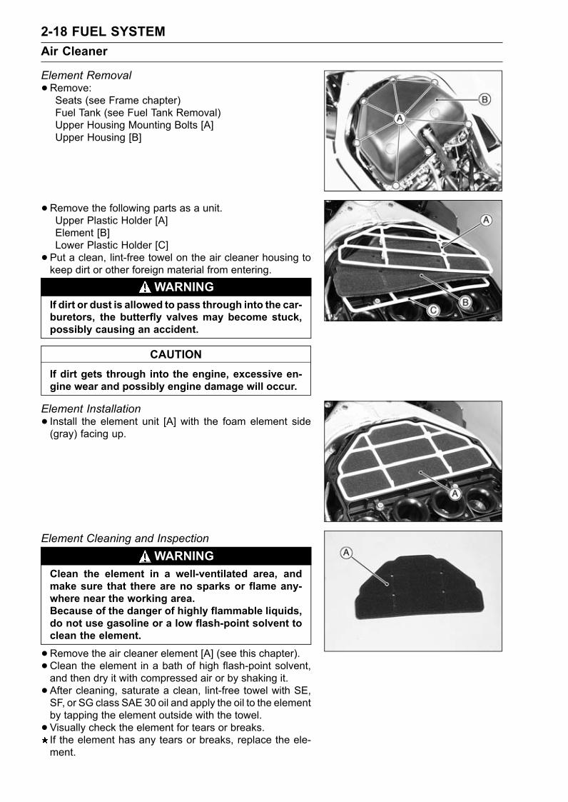
2-18 FUEL SYSTEMAir Cleaner
Element Removal•Remove:Seats (see Frame chapter)Fuel Tank (see Fuel Tank Removal)Upper Housing Mounting Bolts [A]Upper Housing [B]
•Remove the following parts as a unit.Upper Plastic Holder [A]Element [B]Lower Plastic Holder [C]• Put a clean, lint-free towel on the air cleaner housing tokeep dirt or other foreign material from entering.
WARNINGIf dirt or dust is allowed to pass through into the car-buretors, the butterfly valves may become stuck,possibly causing an accident.
CAUTIONIf dirt gets through into the engine, excessive en-gine wear and possibly engine damage will occur.
Element Installation• Install the element unit [A] with the foam element side(gray) facing up.
Element Cleaning and InspectionWARNING
Clean the element in a well-ventilated area, andmake sure that there are no sparks or flame any-where near the working area.Because of the danger of highly flammable liquids,do not use gasoline or a low flash-point solvent toclean the element.
•Remove the air cleaner element [A] (see this chapter).• Clean the element in a bath of high flash-point solvent,and then dry it with compressed air or by shaking it.• After cleaning, saturate a clean, lint-free towel with SE,SF, or SG class SAE 30 oil and apply the oil to the elementby tapping the element outside with the towel.• Visually check the element for tears or breaks.If the element has any tears or breaks, replace the ele-ment.
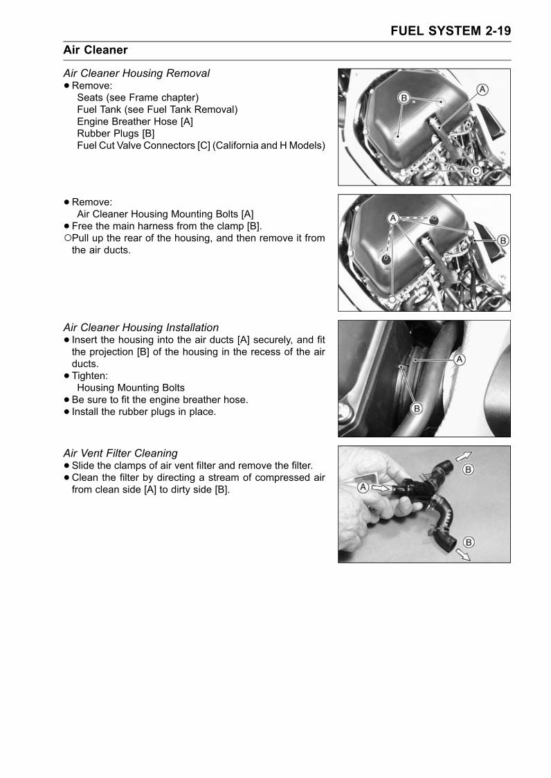
FUEL SYSTEM 2-19Air Cleaner
Air Cleaner Housing Removal•Remove:Seats (see Frame chapter)Fuel Tank (see Fuel Tank Removal)Engine Breather Hose [A]Rubber Plugs [B]Fuel Cut Valve Connectors [C] (California and HModels)
•Remove:Air Cleaner Housing Mounting Bolts [A]• Free the main harness from the clamp [B].Pull up the rear of the housing, and then remove it fromthe air ducts.
Air Cleaner Housing Installation• Insert the housing into the air ducts [A] securely, and fitthe projection [B] of the housing in the recess of the airducts.• Tighten:Housing Mounting Bolts• Be sure to fit the engine breather hose.• Install the rubber plugs in place.
Air Vent Filter Cleaning•Slide the clamps of air vent filter and remove the filter.• Clean the filter by directing a stream of compressed airfrom clean side [A] to dirty side [B].
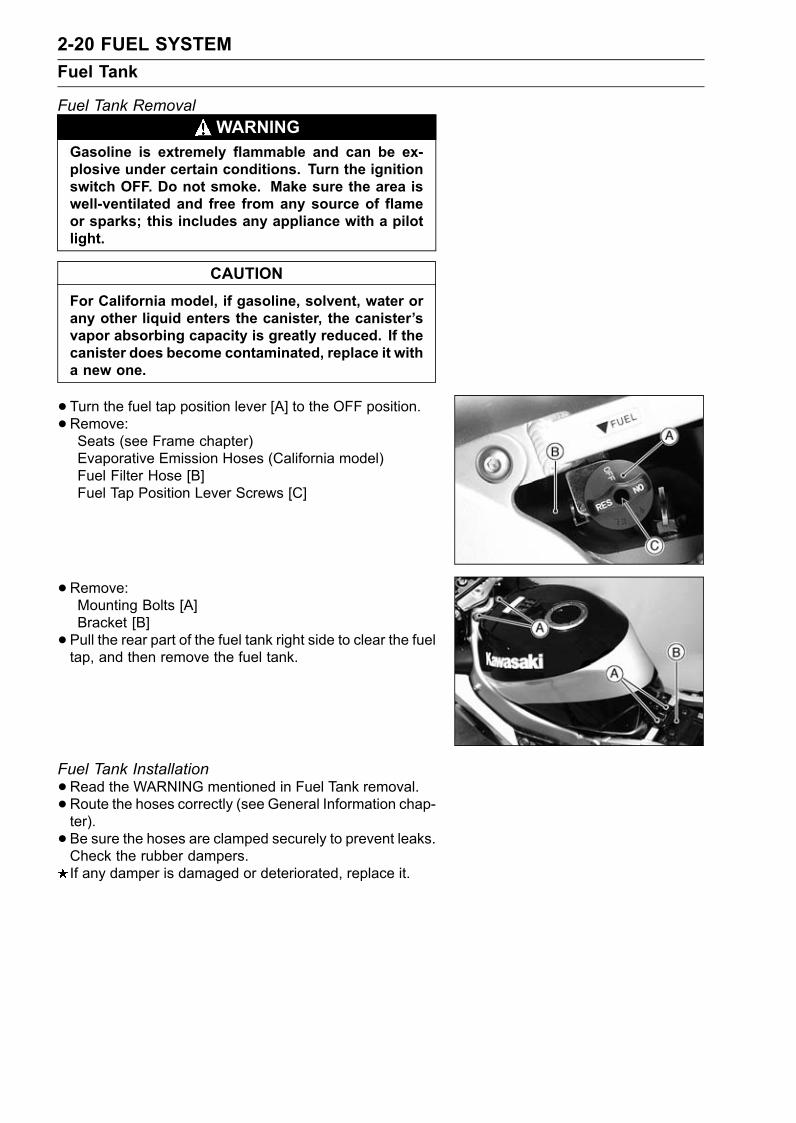
2-20 FUEL SYSTEMFuel Tank
Fuel Tank RemovalWARNING
Gasoline is extremely flammable and can be ex-plosive under certain conditions. Turn the ignitionswitch OFF. Do not smoke. Make sure the area iswell-ventilated and free from any source of flameor sparks; this includes any appliance with a pilotlight.
CAUTIONFor California model, if gasoline, solvent, water orany other liquid enters the canister, the canister’svapor absorbing capacity is greatly reduced. If thecanister does become contaminated, replace it witha new one.
•Turn the fuel tap position lever [A] to the OFF position.•Remove:Seats (see Frame chapter)Evaporative Emission Hoses (California model)Fuel Filter Hose [B]Fuel Tap Position Lever Screws [C]
•Remove:Mounting Bolts [A]Bracket [B]• Pull the rear part of the fuel tank right side to clear the fueltap, and then remove the fuel tank.
Fuel Tank Installation•Read the WARNING mentioned in Fuel Tank removal.• Route the hoses correctly (see General Information chap-ter).• Be sure the hoses are clamped securely to prevent leaks.Check the rubber dampers.If any damper is damaged or deteriorated, replace it.
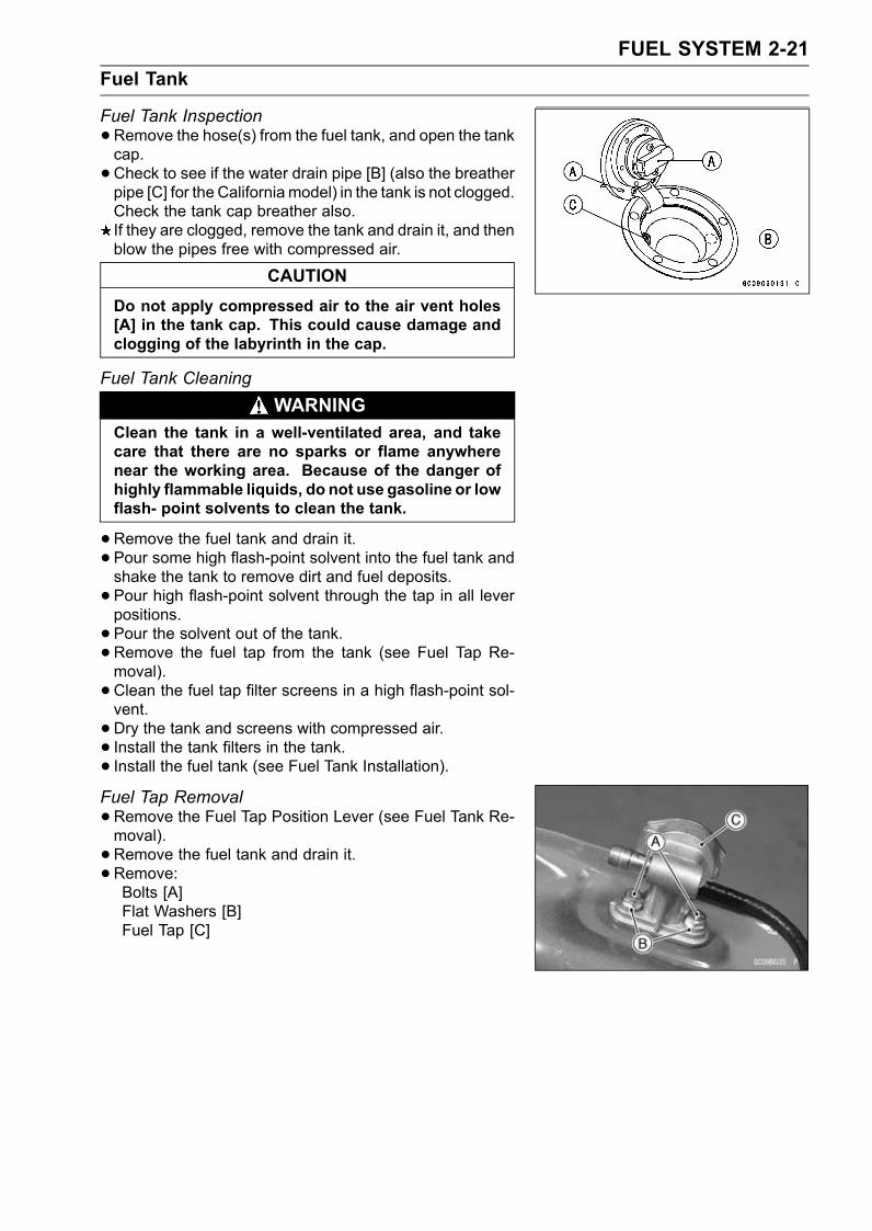
FUEL SYSTEM 2-21Fuel Tank
Fuel Tank Inspection•Remove the hose(s) from the fuel tank, and open the tankcap.•Check to see if the water drain pipe [B] (also the breatherpipe [C] for the Californiamodel) in the tank is not clogged.Check the tank cap breather also.If they are clogged, remove the tank and drain it, and thenblow the pipes free with compressed air.
CAUTIONDo not apply compressed air to the air vent holes[A] in the tank cap. This could cause damage andclogging of the labyrinth in the cap.
Fuel Tank CleaningWARNING
Clean the tank in a well-ventilated area, and takecare that there are no sparks or flame anywherenear the working area. Because of the danger ofhighly flammable liquids, do not use gasoline or lowflash- point solvents to clean the tank.
•Remove the fuel tank and drain it.• Pour some high flash-point solvent into the fuel tank andshake the tank to remove dirt and fuel deposits.• Pour high flash-point solvent through the tap in all leverpositions.• Pour the solvent out of the tank.•Remove the fuel tap from the tank (see Fuel Tap Re-moval).• Clean the fuel tap filter screens in a high flash-point sol-vent.• Dry the tank and screens with compressed air.• Install the tank filters in the tank.• Install the fuel tank (see Fuel Tank Installation).Fuel Tap Removal•Remove the Fuel Tap Position Lever (see Fuel Tank Re-moval).• Remove the fuel tank and drain it.• Remove:Bolts [A]Flat Washers [B]Fuel Tap [C]
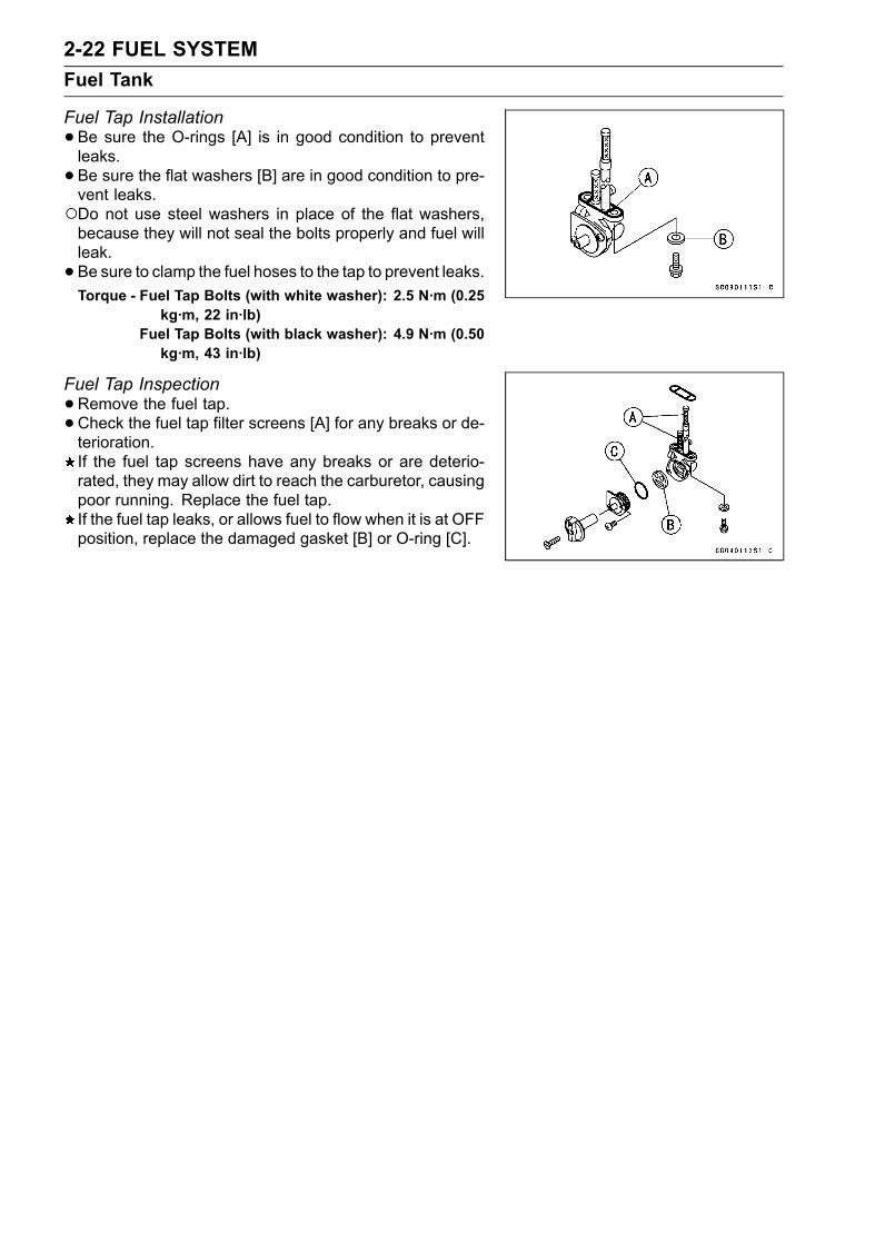
2-22 FUEL SYSTEMFuel Tank
Fuel Tap Installation•Be sure the O-rings [A] is in good condition to preventleaks.• Be sure the flat washers [B] are in good condition to pre-vent leaks.Do not use steel washers in place of the flat washers,because they will not seal the bolts properly and fuel willleak.• Be sure to clamp the fuel hoses to the tap to prevent leaks.Torque - Fuel Tap Bolts (with white washer): 2.5 N·m (0.25
kg·m, 22 in·lb)Fuel Tap Bolts (with black washer): 4.9 N·m (0.50kg·m, 43 in·lb)
Fuel Tap Inspection•Remove the fuel tap.•Check the fuel tap filter screens [A] for any breaks or de-terioration.If the fuel tap screens have any breaks or are deterio-rated, they may allow dirt to reach the carburetor, causingpoor running. Replace the fuel tap.If the fuel tap leaks, or allows fuel to flow when it is at OFFposition, replace the damaged gasket [B] or O-ring [C].
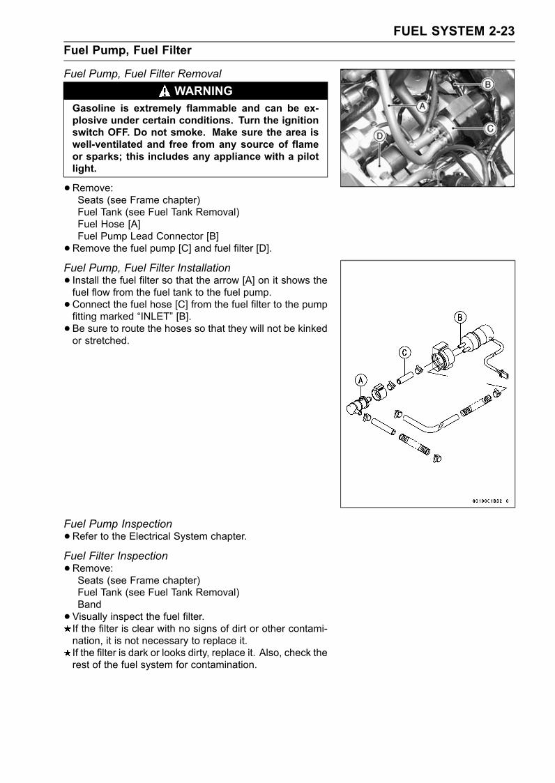
FUEL SYSTEM 2-23Fuel Pump, Fuel Filter
Fuel Pump, Fuel Filter RemovalWARNING
Gasoline is extremely flammable and can be ex-plosive under certain conditions. Turn the ignitionswitch OFF. Do not smoke. Make sure the area iswell-ventilated and free from any source of flameor sparks; this includes any appliance with a pilotlight.
•Remove:Seats (see Frame chapter)Fuel Tank (see Fuel Tank Removal)Fuel Hose [A]Fuel Pump Lead Connector [B]•Remove the fuel pump [C] and fuel filter [D].Fuel Pump, Fuel Filter Installation• Install the fuel filter so that the arrow [A] on it shows thefuel flow from the fuel tank to the fuel pump.•Connect the fuel hose [C] from the fuel filter to the pumpfitting marked “INLET” [B].• Be sure to route the hoses so that they will not be kinkedor stretched.
Fuel Pump Inspection•Refer to the Electrical System chapter.
Fuel Filter Inspection•Remove:Seats (see Frame chapter)Fuel Tank (see Fuel Tank Removal)Band•Visually inspect the fuel filter.If the filter is clear with no signs of dirt or other contami-nation, it is not necessary to replace it.If the filter is dark or looks dirty, replace it. Also, check therest of the fuel system for contamination.
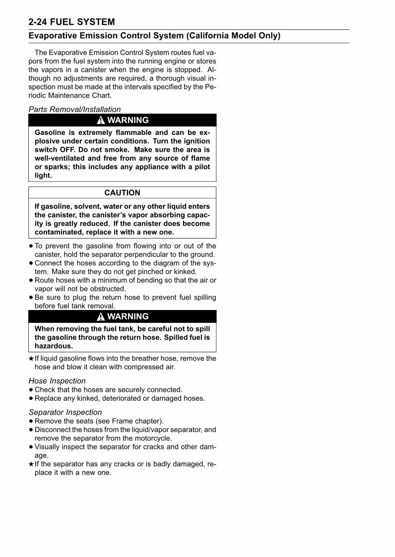
2-24 FUEL SYSTEMEvaporative Emission Control System (California Model Only)
The Evaporative Emission Control System routes fuel va-pors from the fuel system into the running engine or storesthe vapors in a canister when the engine is stopped. Al-though no adjustments are required, a thorough visual in-spection must be made at the intervals specified by the Pe-riodic Maintenance Chart.
Parts Removal/InstallationWARNING
Gasoline is extremely flammable and can be ex-plosive under certain conditions. Turn the ignitionswitch OFF. Do not smoke. Make sure the area iswell-ventilated and free from any source of flameor sparks; this includes any appliance with a pilotlight.
CAUTIONIf gasoline, solvent, water or any other liquid entersthe canister, the canister’s vapor absorbing capac-ity is greatly reduced. If the canister does becomecontaminated, replace it with a new one.
•To prevent the gasoline from flowing into or out of thecanister, hold the separator perpendicular to the ground.•Connect the hoses according to the diagram of the sys-tem. Make sure they do not get pinched or kinked.•Route hoses with a minimum of bending so that the air orvapor will not be obstructed.• Be sure to plug the return hose to prevent fuel spillingbefore fuel tank removal.
WARNINGWhen removing the fuel tank, be careful not to spillthe gasoline through the return hose. Spilled fuel ishazardous.If liquid gasoline flows into the breather hose, remove thehose and blow it clean with compressed air.
Hose Inspection•Check that the hoses are securely connected.•Replace any kinked, deteriorated or damaged hoses.Separator Inspection•Remove the seats (see Frame chapter).• Disconnect the hoses from the liquid/vapor separator, andremove the separator from the motorcycle.• Visually inspect the separator for cracks and other dam-age.If the separator has any cracks or is badly damaged, re-place it with a new one.
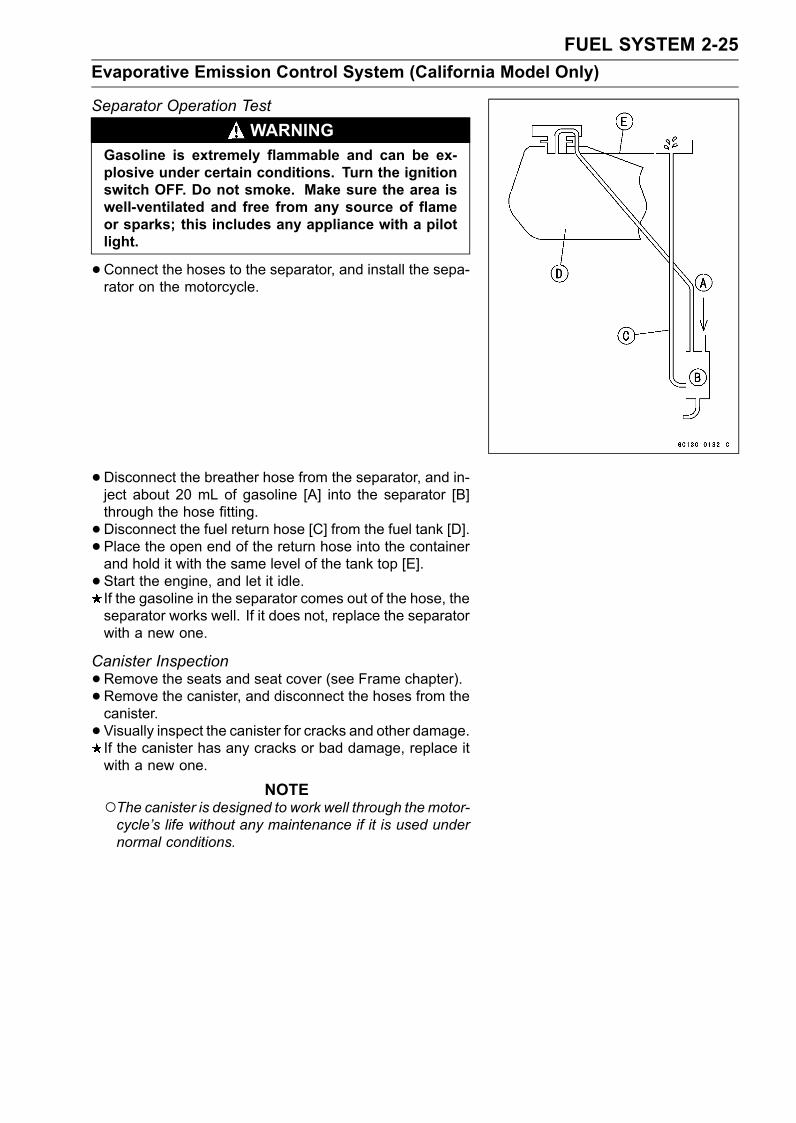
FUEL SYSTEM 2-25Evaporative Emission Control System (California Model Only)
Separator Operation TestWARNING
Gasoline is extremely flammable and can be ex-plosive under certain conditions. Turn the ignitionswitch OFF. Do not smoke. Make sure the area iswell-ventilated and free from any source of flameor sparks; this includes any appliance with a pilotlight.
•Connect the hoses to the separator, and install the sepa-rator on the motorcycle.
•Disconnect the breather hose from the separator, and in-ject about 20 mL of gasoline [A] into the separator [B]through the hose fitting.•Disconnect the fuel return hose [C] from the fuel tank [D].• Place the open end of the return hose into the containerand hold it with the same level of the tank top [E].• Start the engine, and let it idle.If the gasoline in the separator comes out of the hose, theseparator works well. If it does not, replace the separatorwith a new one.
Canister Inspection•Remove the seats and seat cover (see Frame chapter).• Remove the canister, and disconnect the hoses from thecanister.• Visually inspect the canister for cracks and other damage.If the canister has any cracks or bad damage, replace itwith a new one.
NOTEThe canister is designed to work well through the motor-cycle’s life without any maintenance if it is used undernormal conditions.
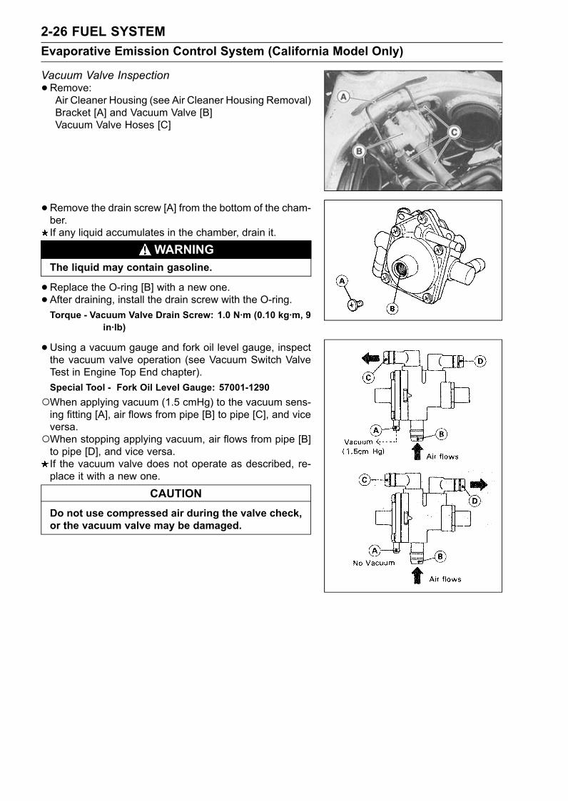
2-26 FUEL SYSTEMEvaporative Emission Control System (California Model Only)
Vacuum Valve Inspection•Remove:Air Cleaner Housing (see Air Cleaner Housing Removal)Bracket [A] and Vacuum Valve [B]Vacuum Valve Hoses [C]
•Remove the drain screw [A] from the bottom of the cham-ber.If any liquid accumulates in the chamber, drain it.
WARNINGThe liquid may contain gasoline.
•Replace the O-ring [B] with a new one.• After draining, install the drain screw with the O-ring.Torque - Vacuum Valve Drain Screw: 1.0 N·m (0.10 kg·m, 9
in·lb)
•Using a vacuum gauge and fork oil level gauge, inspectthe vacuum valve operation (see Vacuum Switch ValveTest in Engine Top End chapter).Special Tool - Fork Oil Level Gauge: 57001-1290When applying vacuum (1.5 cmHg) to the vacuum sens-ing fitting [A], air flows from pipe [B] to pipe [C], and viceversa.When stopping applying vacuum, air flows from pipe [B]to pipe [D], and vice versa.If the vacuum valve does not operate as described, re-place it with a new one.
CAUTIONDo not use compressed air during the valve check,or the vacuum valve may be damaged.
COOLING SYSTEM 3-1
3
Cooling System
Table of ContentsExploded View........................................................................................................................ 3-2Specifications ......................................................................................................................... 3-3Coolant Flow Chart................................................................................................................. 3-4Coolant ................................................................................................................................... 3-6
Coolant Deterioration Inspection....................................................................................... 3-6Coolant Level Inspection................................................................................................... 3-6Coolant Draining ............................................................................................................... 3-6Coolant Filling ................................................................................................................... 3-7Pressure Testing ............................................................................................................... 3-8Cooling System Flushing .................................................................................................. 3-9Coolant Filter Cleaning ..................................................................................................... 3-9
Water Pump............................................................................................................................ 3-10Water Pump Removal....................................................................................................... 3-10Water Pump Installation.................................................................................................... 3-10Water Pump Inspection..................................................................................................... 3-10
Radiator, Radiator Fan ........................................................................................................... 3-11Radiator and Radiator Fan Removal ................................................................................ 3-11Radiator Inspection ........................................................................................................... 3-12Radiator Cap Inspection ................................................................................................... 3-12
Thermostat ............................................................................................................................. 3-13Thermostat Removal......................................................................................................... 3-13Thermostat Installation...................................................................................................... 3-13Thermostat Inspection ...................................................................................................... 3-13
Hose and Pipes ...................................................................................................................... 3-14Hose Installation ............................................................................................................... 3-14Hose Inspection ................................................................................................................ 3-14
Radiator Fan Switch, Water Temperature Sensor .................................................................. 3-15Radiator Fan Switch, Water Temperature Sensor Removal ............................................. 3-15Radiator Fan Switch, Water Temperature Sensor Installation .......................................... 3-15Radiator Fan Switch, Water Temperature Sensor Inspection ........................................... 3-15
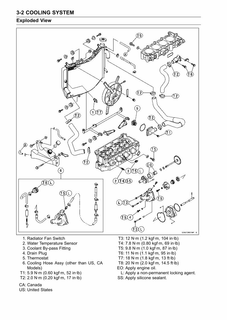
3-2 COOLING SYSTEMExploded View
1. Radiator Fan Switch2. Water Temperature Sensor3. Coolant By-pass Fitting4. Drain Plug5. Thermostat6. Cooling Hose Assy (other than US, CAModels)
T1: 5.9 N·m (0.60 kgf·m, 52 in·lb)T2: 2.0 N·m (0.20 kgf·m, 17 in·lb)
T3: 12 N·m (1.2 kgf·m, 104 in·lb)T4: 7.8 N·m (0.80 kgf·m, 69 in·lb)T5: 9.8 N·m (1.0 kgf·m, 87 in·lb)T6: 11 N·m (1.1 kgf·m, 95 in·lb)T7: 18 N·m (1.8 kgf·m, 13 ft·lb)T8: 20 N·m (2.0 kgf·m, 14.5 ft·lb)EO: Apply engine oil.L: Apply a non-permanent locking agent.
SS: Apply silicone sealant.
CA: CanadaUS: United States
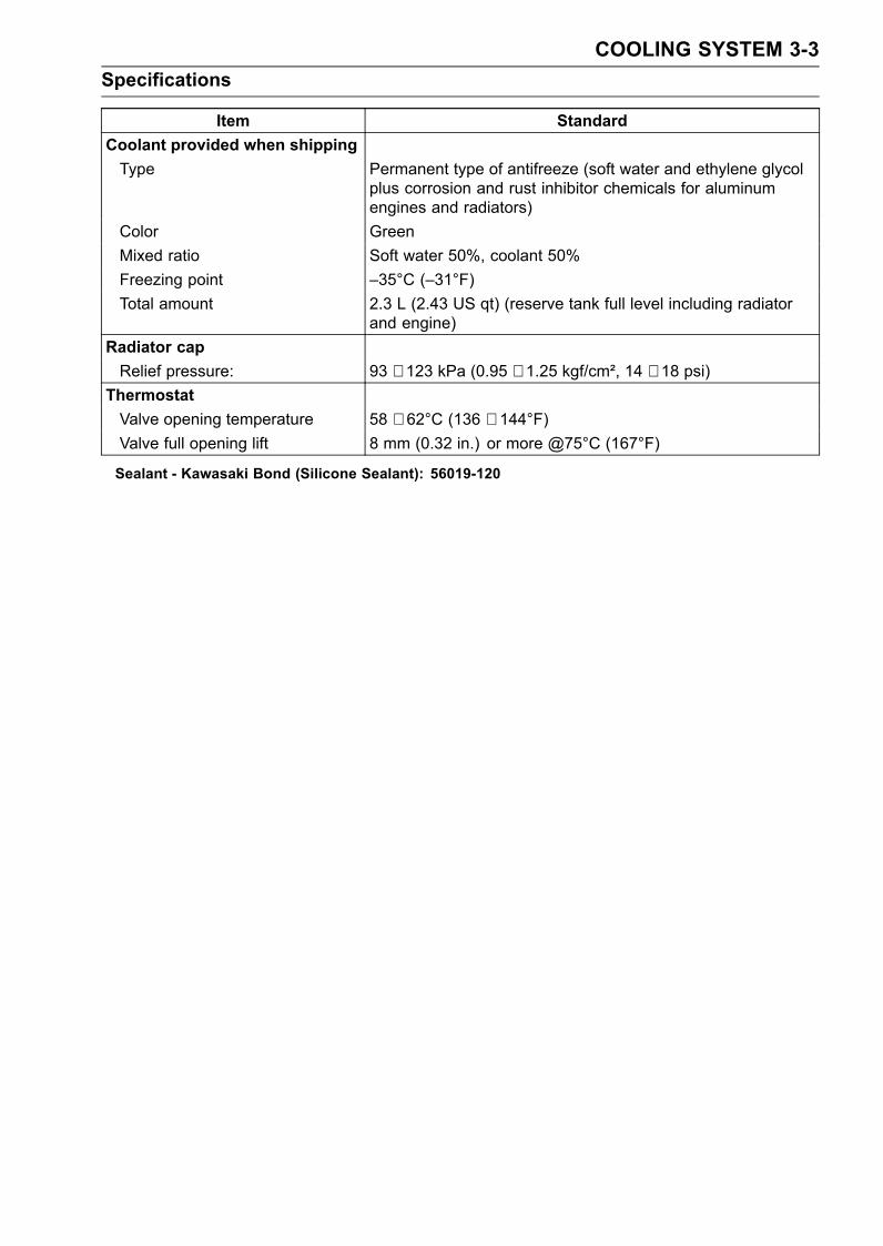
COOLING SYSTEM 3-3Specifications
Item StandardCoolant provided when shippingType Permanent type of antifreeze (soft water and ethylene glycol
plus corrosion and rust inhibitor chemicals for aluminumengines and radiators)
Color GreenMixed ratio Soft water 50%, coolant 50%Freezing point –35°C (–31°F)Total amount 2.3 L (2.43 US qt) (reserve tank full level including radiator
and engine)Radiator capRelief pressure: 93 ∼ 123 kPa (0.95 ∼ 1.25 kgf/cm², 14 ∼ 18 psi)
ThermostatValve opening temperature 58 ∼ 62°C (136 ∼ 144°F)Valve full opening lift 8 mm (0.32 in.) or more @75°C (167°F)
Sealant - Kawasaki Bond (Silicone Sealant): 56019-120
3-4 COOLING SYSTEMCoolant Flow Chart
Permanent type antifreeze is used as a coolant to protect the cooling system from rust and corrosion.When the engine starts, the water pump turns and the coolant circulates.The thermostat is a wax pellet type which opens or closes with coolant temperature changes. The
thermostat continuously changes its valve opening to keep the coolant temperature at the proper level.When coolant temperature is below 55°C (131°F), the thermostat closes so that the coolant flow isrestricted through the air bleeder hole, causing the engine to warm up more quickly. When coolanttemperature is 58 ∼ 62°C (136 ∼ 144°F), the thermostat opens and the coolant flows.When the coolant temperature goes up beyond 96 ∼ 100°C (205 ∼ 212°F), the radiator fan switch
conducts to operate the radiator fan. The radiator fan draws air through the radiator core when thereis not sufficient air flow such as at low speeds. This increases up the cooling action of the radiator.When the temperature is below 91°C (196°F), the fan switch opens and the radiator fan stops.In this way, this system controls the engine temperature within narrow limits where the engine op-
erates most efficiently even if the engine load varies.The system is pressurized by the radiator cap to suppress boiling and the resultant air bubbles
which can cause engine overheating. As the engine warms up, the coolant in the radiator and thewater jacket expands. The excess coolant flows through the radiator cap and hose to the reserve tankto be stored there temporarily. Conversely, as the engine cools down, the coolant in the radiator andthe water jacket contracts, and the stored coolant flows back to the radiator from the reserve tank.The radiator cap has two valves. One is a pressure valve which holds the pressure in the system
when the engine is running. When the pressure exceeds 93 ∼ 123 kPa (0.95 ∼ 1.25 kgf/m², 14 ∼ 18psi) the pressure valve opens and releases the pressure to the reserve tank. As soon as pressureescapes, the valve closes, and keeps the pressure at 93 ∼ 123 kPa (0.95 ∼ 1.25 kgf/m², 14 ∼ 18 psi).When the engine cools down, another small valve (vacuum valve) in the cap opens. As the coolantcools, the coolant contracts to form a vacuum in the system. The vacuum valve opens and allows thecoolant from the reserve tank to enter the radiator.
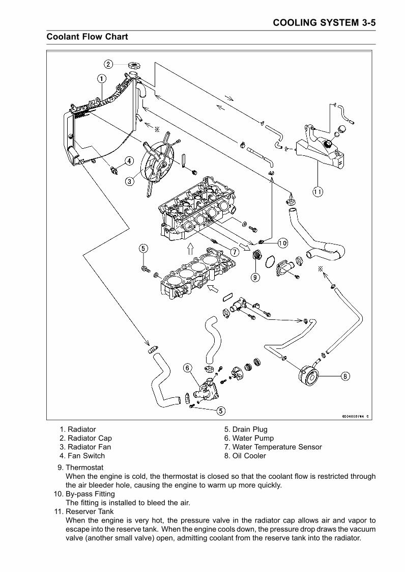
COOLING SYSTEM 3-5Coolant Flow Chart
1. Radiator2. Radiator Cap3. Radiator Fan4. Fan Switch
5. Drain Plug6. Water Pump7. Water Temperature Sensor8. Oil Cooler
9. ThermostatWhen the engine is cold, the thermostat is closed so that the coolant flow is restricted throughthe air bleeder hole, causing the engine to warm up more quickly.
10. By-pass FittingThe fitting is installed to bleed the air.
11. Reserver TankWhen the engine is very hot, the pressure valve in the radiator cap allows air and vapor toescape into the reserve tank. When the engine cools down, the pressure drop draws the vacuumvalve (another small valve) open, admitting coolant from the reserve tank into the radiator.
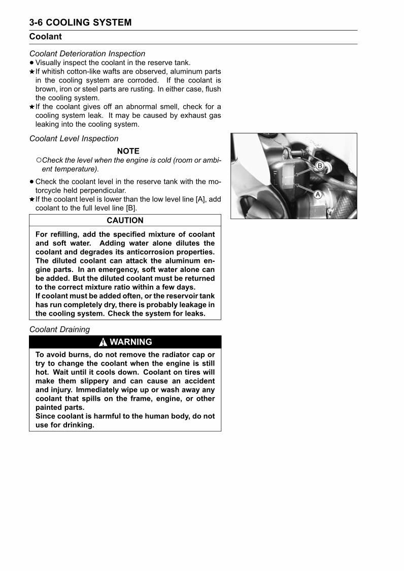
3-6 COOLING SYSTEMCoolant
Coolant Deterioration Inspection•Visually inspect the coolant in the reserve tank.If whitish cotton-like wafts are observed, aluminum partsin the cooling system are corroded. If the coolant isbrown, iron or steel parts are rusting. In either case, flushthe cooling system.If the coolant gives off an abnormal smell, check for acooling system leak. It may be caused by exhaust gasleaking into the cooling system.
Coolant Level InspectionNOTE
Check the level when the engine is cold (room or ambi-ent temperature).
•Check the coolant level in the reserve tank with the mo-torcycle held perpendicular.If the coolant level is lower than the low level line [A], addcoolant to the full level line [B].
CAUTIONFor refilling, add the specified mixture of coolantand soft water. Adding water alone dilutes thecoolant and degrades its anticorrosion properties.The diluted coolant can attack the aluminum en-gine parts. In an emergency, soft water alone canbe added. But the diluted coolant must be returnedto the correct mixture ratio within a few days.If coolant must be added often, or the reservoir tankhas run completely dry, there is probably leakage inthe cooling system. Check the system for leaks.
Coolant DrainingWARNING
To avoid burns, do not remove the radiator cap ortry to change the coolant when the engine is stillhot. Wait until it cools down. Coolant on tires willmake them slippery and can cause an accidentand injury. Immediately wipe up or wash away anycoolant that spills on the frame, engine, or otherpainted parts.Since coolant is harmful to the human body, do notuse for drinking.
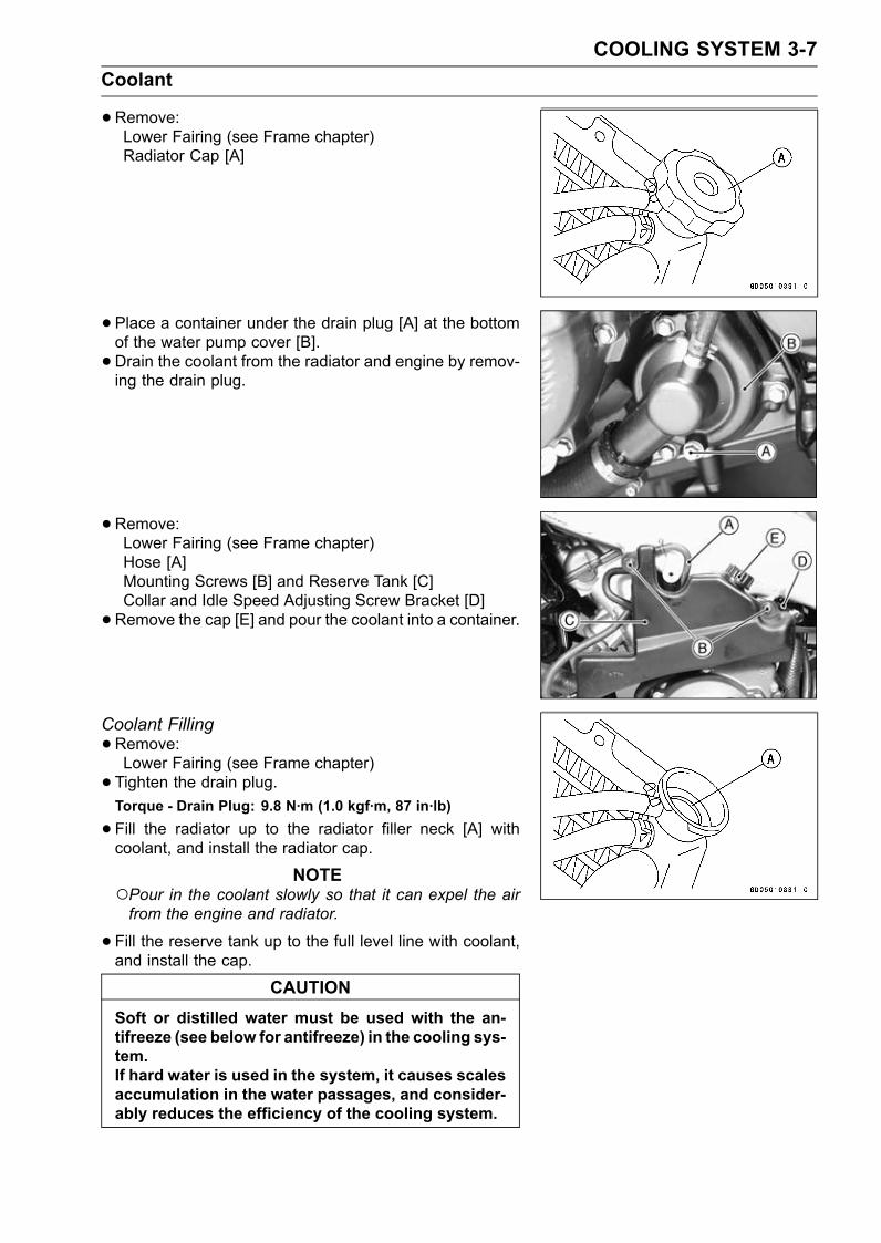
COOLING SYSTEM 3-7Coolant
•Remove:Lower Fairing (see Frame chapter)Radiator Cap [A]
• Place a container under the drain plug [A] at the bottomof the water pump cover [B].• Drain the coolant from the radiator and engine by remov-ing the drain plug.
•Remove:Lower Fairing (see Frame chapter)Hose [A]Mounting Screws [B] and Reserve Tank [C]Collar and Idle Speed Adjusting Screw Bracket [D]•Remove the cap [E] and pour the coolant into a container.
Coolant Filling•Remove:Lower Fairing (see Frame chapter)• Tighten the drain plug.Torque - Drain Plug: 9.8 N·m (1.0 kgf·m, 87 in·lb)
•Fill the radiator up to the radiator filler neck [A] withcoolant, and install the radiator cap.
NOTEPour in the coolant slowly so that it can expel the airfrom the engine and radiator.
•Fill the reserve tank up to the full level line with coolant,and install the cap.
CAUTIONSoft or distilled water must be used with the an-tifreeze (see below for antifreeze) in the cooling sys-tem.If hard water is used in the system, it causes scalesaccumulation in the water passages, and consider-ably reduces the efficiency of the cooling system.
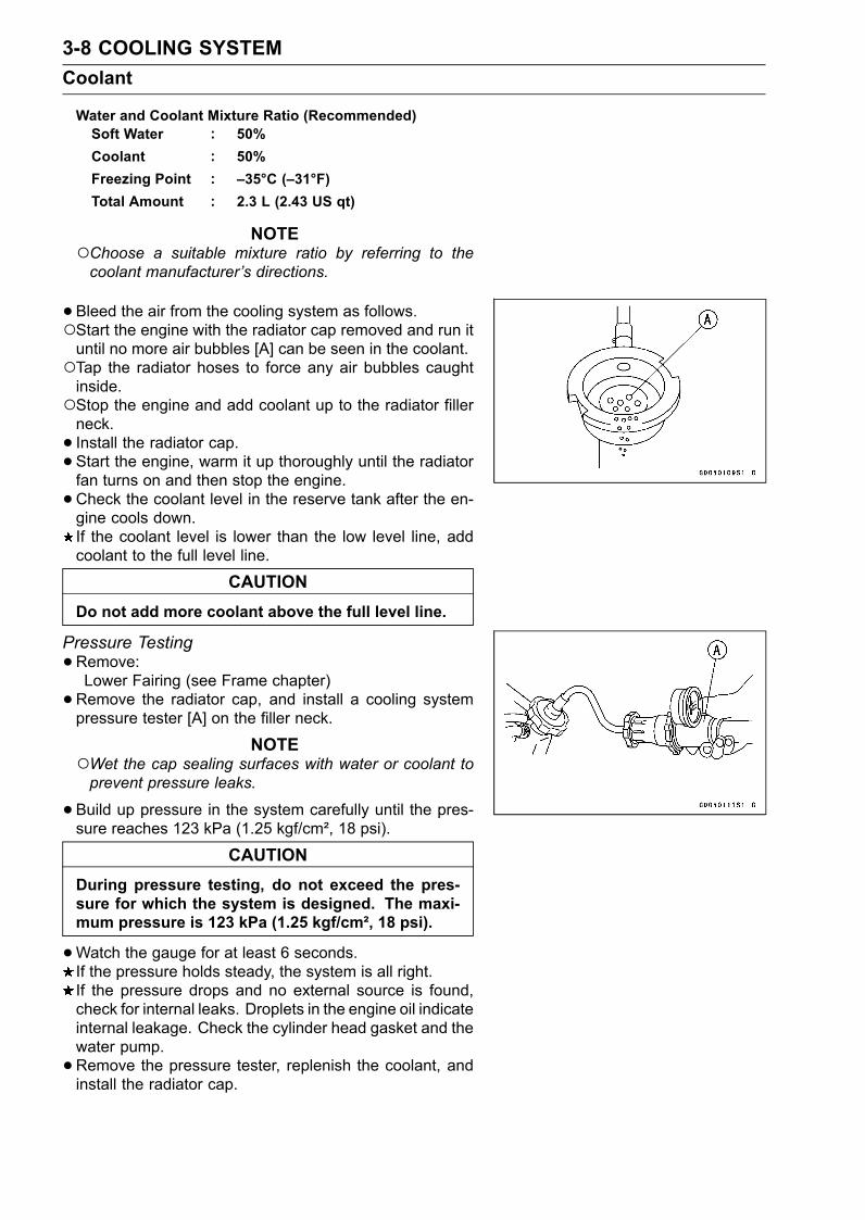
3-8 COOLING SYSTEMCoolant
Water and Coolant Mixture Ratio (Recommended)Soft Water : 50%Coolant : 50%Freezing Point : –35°C (–31°F)Total Amount : 2.3 L (2.43 US qt)
NOTEChoose a suitable mixture ratio by referring to thecoolant manufacturer’s directions.
•Bleed the air from the cooling system as follows.Start the engine with the radiator cap removed and run ituntil no more air bubbles [A] can be seen in the coolant.Tap the radiator hoses to force any air bubbles caughtinside.Stop the engine and add coolant up to the radiator fillerneck.• Install the radiator cap.• Start the engine, warm it up thoroughly until the radiatorfan turns on and then stop the engine.•Check the coolant level in the reserve tank after the en-gine cools down.If the coolant level is lower than the low level line, addcoolant to the full level line.
CAUTIONDo not add more coolant above the full level line.
Pressure Testing•Remove:Lower Fairing (see Frame chapter)•Remove the radiator cap, and install a cooling systempressure tester [A] on the filler neck.
NOTEWet the cap sealing surfaces with water or coolant toprevent pressure leaks.
•Build up pressure in the system carefully until the pres-sure reaches 123 kPa (1.25 kgf/cm², 18 psi).
CAUTIONDuring pressure testing, do not exceed the pres-sure for which the system is designed. The maxi-mum pressure is 123 kPa (1.25 kgf/cm², 18 psi).
•Watch the gauge for at least 6 seconds.If the pressure holds steady, the system is all right.If the pressure drops and no external source is found,check for internal leaks. Droplets in the engine oil indicateinternal leakage. Check the cylinder head gasket and thewater pump.•Remove the pressure tester, replenish the coolant, andinstall the radiator cap.
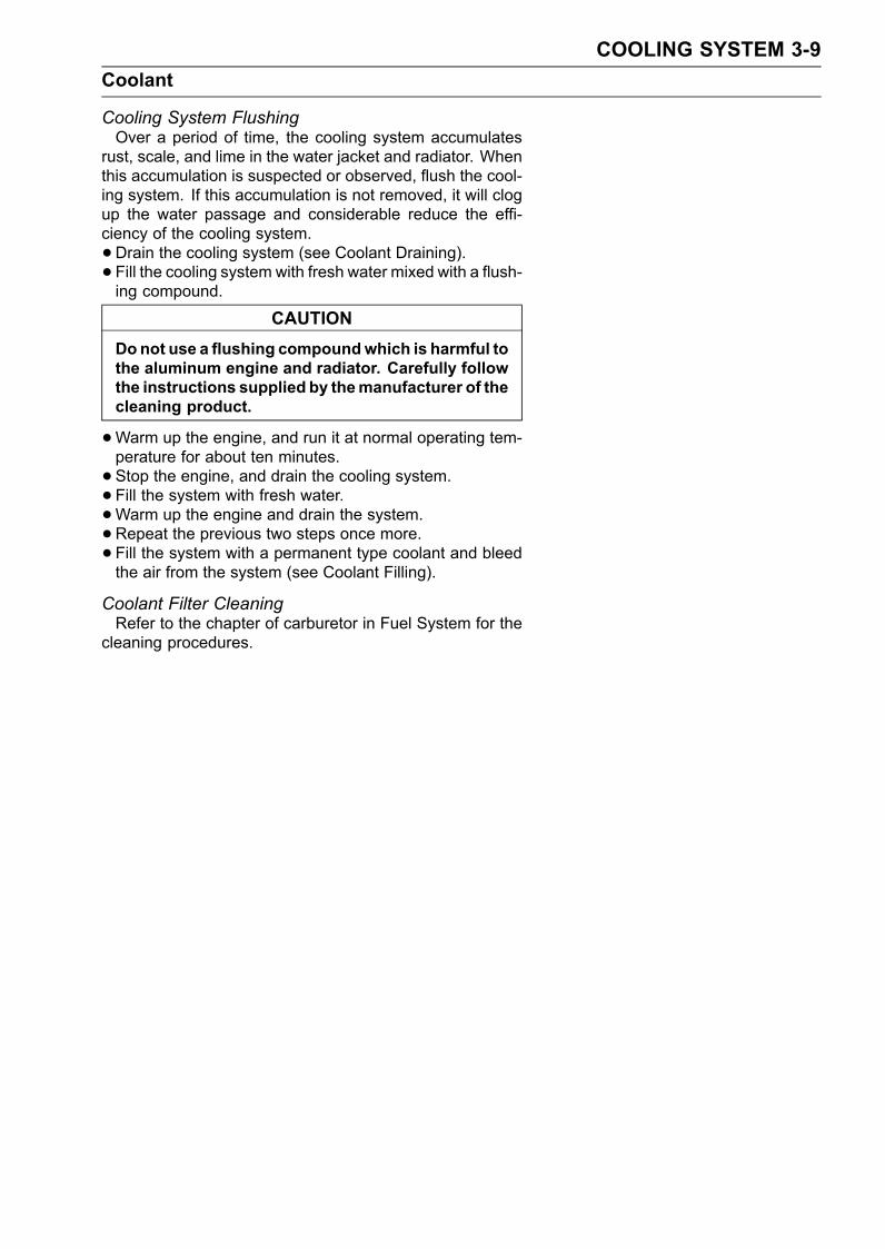
COOLING SYSTEM 3-9Coolant
Cooling System FlushingOver a period of time, the cooling system accumulates
rust, scale, and lime in the water jacket and radiator. Whenthis accumulation is suspected or observed, flush the cool-ing system. If this accumulation is not removed, it will clogup the water passage and considerable reduce the effi-ciency of the cooling system.•Drain the cooling system (see Coolant Draining).• Fill the cooling system with fresh water mixed with a flush-ing compound.
CAUTIONDonot use a flushing compoundwhich is harmful tothe aluminum engine and radiator. Carefully followthe instructions supplied by themanufacturer of thecleaning product.
•Warm up the engine, and run it at normal operating tem-perature for about ten minutes.• Stop the engine, and drain the cooling system.• Fill the system with fresh water.•Warm up the engine and drain the system.•Repeat the previous two steps once more.• Fill the system with a permanent type coolant and bleedthe air from the system (see Coolant Filling).
Coolant Filter CleaningRefer to the chapter of carburetor in Fuel System for the
cleaning procedures.
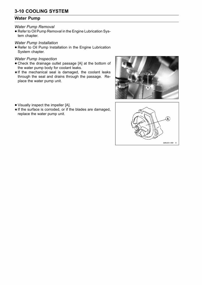
3-10 COOLING SYSTEMWater Pump
Water Pump Removal•Refer to Oil PumpRemoval in the Engine Lubrication Sys-tem chapter.
Water Pump Installation•Refer to Oil Pump Installation in the Engine LubricationSystem chapter.
Water Pump Inspection•Check the drainage outlet passage [A] at the bottom ofthe water pump body for coolant leaks.If the mechanical seal is damaged, the coolant leaksthrough the seal and drains through the passage. Re-place the water pump unit.
• Visually inspect the impeller [A].If the surface is corroded, or if the blades are damaged,replace the water pump unit.
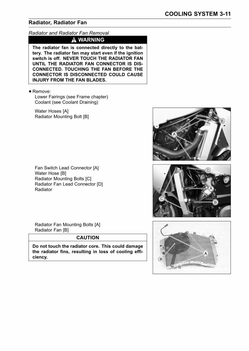
COOLING SYSTEM 3-11Radiator, Radiator Fan
Radiator and Radiator Fan RemovalWARNING
The radiator fan is connected directly to the bat-tery. The radiator fan may start even if the ignitionswitch is off. NEVER TOUCH THE RADIATOR FANUNTIL THE RADIATOR FAN CONNECTOR IS DIS-CONNECTED. TOUCHING THE FAN BEFORE THECONNECTOR IS DISCONNECTED COULD CAUSEINJURY FROM THE FAN BLADES.
•Remove:Lower Fairings (see Frame chapter)Coolant (see Coolant Draining)
Water Hoses [A]Radiator Mounting Bolt [B]
Fan Switch Lead Connector [A]Water Hose [B]Radiator Mounting Bolts [C]Radiator Fan Lead Connector [D]Radiator
Radiator Fan Mounting Bolts [A]Radiator Fan [B]
CAUTIONDo not touch the radiator core. This could damagethe radiator fins, resulting in loss of cooling effi-ciency.
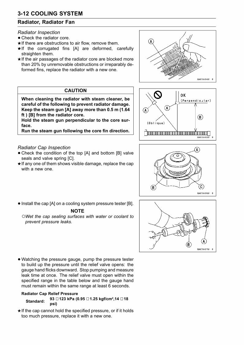
3-12 COOLING SYSTEMRadiator, Radiator Fan
Radiator Inspection•Check the radiator core.If there are obstructions to air flow, remove them.If the corrugated fins [A] are deformed, carefullystraighten them.If the air passages of the radiator core are blocked morethan 20% by unremovable obstructions or irreparably de-formed fins, replace the radiator with a new one.
CAUTIONWhen cleaning the radiator with steam cleaner, becareful of the following to prevent radiator damage.Keep the steam gun [A] away more than 0.5 m (1.64ft ) [B] from the radiator core.Hold the steam gun perpendicular to the core sur-face.Run the steam gun following the core fin direction.
Radiator Cap Inspection•Check the condition of the top [A] and bottom [B] valveseals and valve spring [C].If any one of them shows visible damage, replace the capwith a new one.
• Install the cap [A] on a cooling system pressure tester [B].NOTE
Wet the cap sealing surfaces with water or coolant toprevent pressure leaks.
•Watching the pressure gauge, pump the pressure testerto build up the pressure until the relief valve opens: thegauge hand flicks downward. Stop pumping andmeasureleak time at once. The relief valve must open within thespecified range in the table below and the gauge handmust remain within the same range at least 6 seconds.
Radiator Cap Relief Pressure
Standard: 93 ∼ 123 kPa (0.95 ∼ 1.25 kgf/cm²,14 ∼ 18psi)
If the cap cannot hold the specified pressure, or if it holdstoo much pressure, replace it with a new one.
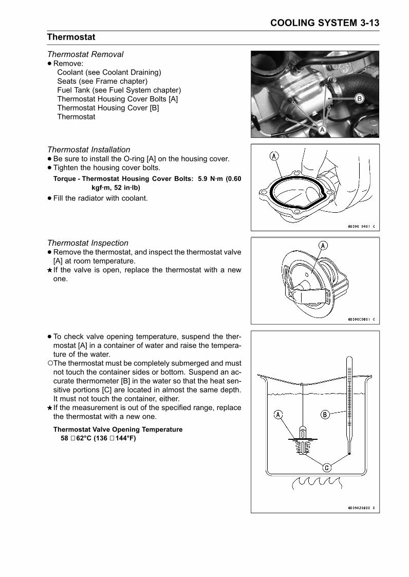
COOLING SYSTEM 3-13Thermostat
Thermostat Removal•Remove:Coolant (see Coolant Draining)Seats (see Frame chapter)Fuel Tank (see Fuel System chapter)Thermostat Housing Cover Bolts [A]Thermostat Housing Cover [B]Thermostat
Thermostat Installation•Be sure to install the O-ring [A] on the housing cover.• Tighten the housing cover bolts.Torque - Thermostat Housing Cover Bolts: 5.9 N·m (0.60
kgf·m, 52 in·lb)
•Fill the radiator with coolant.
Thermostat Inspection•Remove the thermostat, and inspect the thermostat valve[A] at room temperature.If the valve is open, replace the thermostat with a newone.
• To check valve opening temperature, suspend the ther-mostat [A] in a container of water and raise the tempera-ture of the water.The thermostat must be completely submerged and mustnot touch the container sides or bottom. Suspend an ac-curate thermometer [B] in the water so that the heat sen-sitive portions [C] are located in almost the same depth.It must not touch the container, either.If the measurement is out of the specified range, replacethe thermostat with a new one.
Thermostat Valve Opening Temperature58 ∼ 62°C (136 ∼ 144°F)
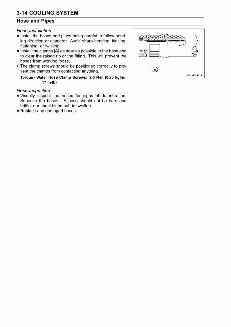
3-14 COOLING SYSTEMHose and Pipes
Hose Installation• Install the hoses and pipes being careful to follow bend-ing direction or diameter. Avoid sharp bending, kinking,flattening, or twisting.• Install the clamps [A] as near as possible to the hose endto clear the raised rib or the fitting. This will prevent thehoses from working loose.The clamp screws should be positioned correctly to pre-vent the clamps from contacting anything.Torque - Water Hose Clamp Screws: 2.0 N·m (0.20 kgf·m,
17 in·lb)
Hose Inspection•Visually inspect the hoses for signs of deterioration.Squeeze the hoses. A hose should not be hard andbrittle, nor should it be soft to swollen.•Replace any damaged hoses.
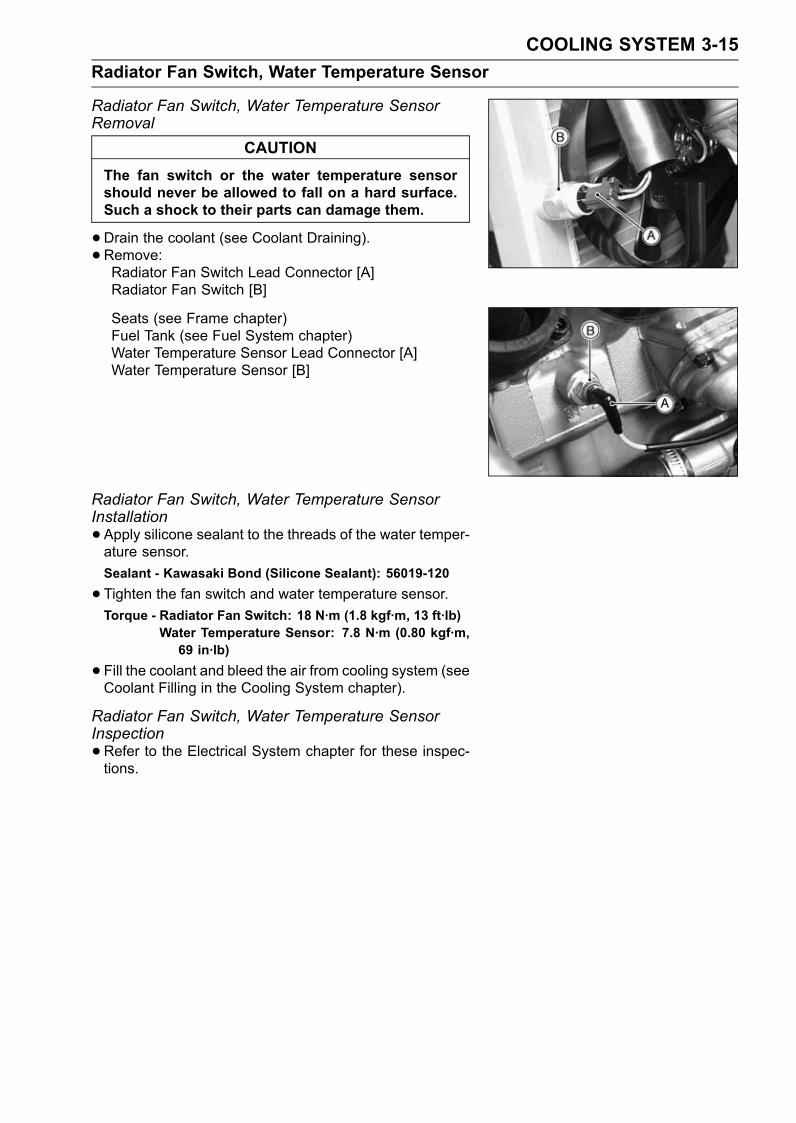
COOLING SYSTEM 3-15Radiator Fan Switch, Water Temperature Sensor
Radiator Fan Switch, Water Temperature SensorRemoval
CAUTIONThe fan switch or the water temperature sensorshould never be allowed to fall on a hard surface.Such a shock to their parts can damage them.
•Drain the coolant (see Coolant Draining).• Remove:Radiator Fan Switch Lead Connector [A]Radiator Fan Switch [B]
Seats (see Frame chapter)Fuel Tank (see Fuel System chapter)Water Temperature Sensor Lead Connector [A]Water Temperature Sensor [B]
Radiator Fan Switch, Water Temperature SensorInstallation•Apply silicone sealant to the threads of the water temper-ature sensor.Sealant - Kawasaki Bond (Silicone Sealant): 56019-120
•Tighten the fan switch and water temperature sensor.Torque - Radiator Fan Switch: 18 N·m (1.8 kgf·m, 13 ft·lb)
Water Temperature Sensor: 7.8 N·m (0.80 kgf·m,69 in·lb)
•Fill the coolant and bleed the air from cooling system (seeCoolant Filling in the Cooling System chapter).
Radiator Fan Switch, Water Temperature SensorInspection•Refer to the Electrical System chapter for these inspec-tions.

ENGINE TOP END 4-1
4
Engine Top End
Table of ContentsExploded View................................... 4-2Specifications .................................... 4-4Clean Air System............................... 4-7
Air Suction Valve Removal........... 4-7Air Suction Valve Installation........ 4-7Air Suction Valve Inspection ........ 4-7Vacuum Switch Valve Removal ... 4-7Vacuum Switch Valve Installation 4-8Vacuum Switch Valve Test ........... 4-8Clean Air System HoseInspection.................................. 4-8
Cylinder Head Cover ......................... 4-9Cylinder Head Cover Removal .... 4-9Cylinder Head Cover Installation . 4-10
Camshaft Chain Tensioner ................ 4-11Camshaft Chain TensionerRemoval .................................... 4-11
Camshaft Chain TensionerInstallation ................................. 4-11
Camshaft, Camshaft Chain ............... 4-12Camshaft Removal ...................... 4-12Camshaft Installation ................... 4-12Camshaft, Camshaft Cap WearInspection.................................. 4-14
Camshaft Runout Inspection........ 4-14Cam Wear Inspection .................. 4-14Camshaft Chain Removal ............ 4-15
Cylinder Head.................................... 4-16Cylinder CompressionMeasurement ............................ 4-16
Cylinder Head Removal ............... 4-17Cylinder Head Installation ............ 4-17Cylinder Head Warp Inspection ... 4-18
Valves ................................................ 4-19
Valve Clearance Inspection ......... 4-19Valve Clearance Adjustment........ 4-20Valve Removal ............................. 4-23Valve Installation .......................... 4-23Valve Guide Removal .................. 4-23Valve Guide Installation ............... 4-24Valve-to-Guide ClearanceMeasurement (WobbleMethod) ..................................... 4-24
Valve Seat Inspection .................. 4-25Valve Seat Repair ........................ 4-25
Cylinder, Pistons................................ 4-30Cylinder Removal......................... 4-30Cylinder Installation...................... 4-30Piston Removal............................ 4-30Piston Installation......................... 4-31Cylinder Wear Inspection............. 4-32Piston Wear Inspection ................ 4-32Piston Ring, Piston Ring GrooveWear Inspection ........................ 4-32
Piston Ring Groove WidthInspection.................................. 4-33
Piston Ring Thickness Inspection 4-33Piston Ring End Gap Inspection .. 4-33
Carburetor Holder.............................. 4-34Carburetor Holder Installation ...... 4-34
Muffler................................................ 4-35Muffler and Exhaust PipeRemoval .................................... 4-35
Muffler and Exhaust PipeInstallation ................................. 4-35
Muffler Body Removal.................. 4-36Muffler Body Installation............... 4-36
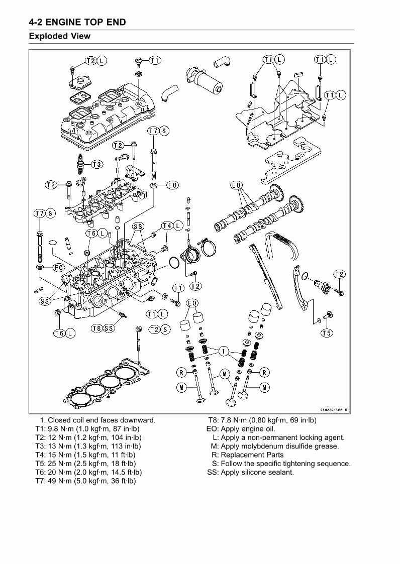
4-2 ENGINE TOP ENDExploded View
1. Closed coil end faces downward.T1: 9.8 N·m (1.0 kgf·m, 87 in·lb)T2: 12 N·m (1.2 kgf·m, 104 in·lb)T3: 13 N·m (1.3 kgf·m, 113 in·lb)T4: 15 N·m (1.5 kgf·m, 11 ft·lb)T5: 25 N·m (2.5 kgf·m, 18 ft·lb)T6: 20 N·m (2.0 kgf·m, 14.5 ft·lb)T7: 49 N·m (5.0 kgf·m, 36 ft·lb)
T8: 7.8 N·m (0.80 kgf·m, 69 in·lb)EO: Apply engine oil.L: Apply a non-permanent locking agent.M: Apply molybdenum disulfide grease.R: Replacement PartsS: Follow the specific tightening sequence.SS: Apply silicone sealant.
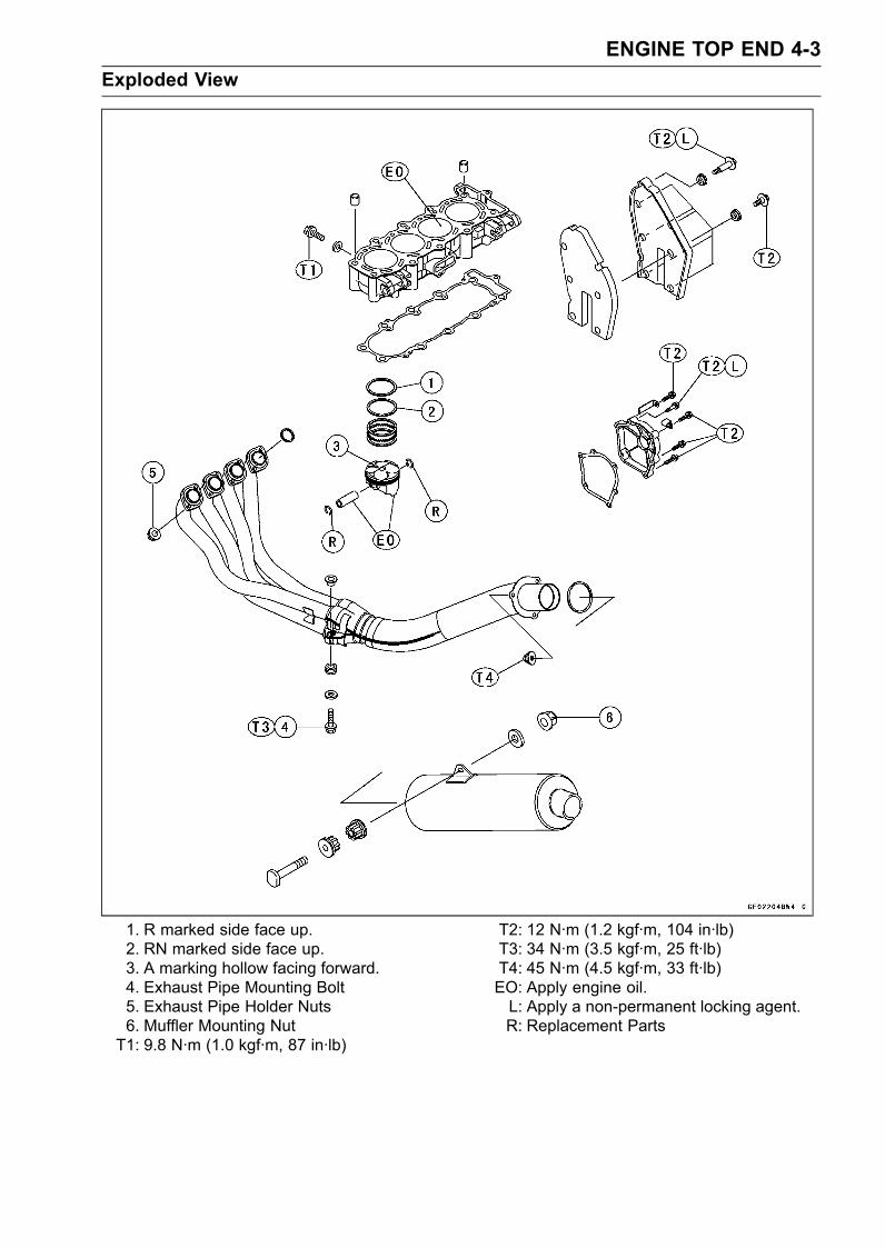
ENGINE TOP END 4-3Exploded View
1. R marked side face up.2. RN marked side face up.3. A marking hollow facing forward.4. Exhaust Pipe Mounting Bolt5. Exhaust Pipe Holder Nuts6. Muffler Mounting NutT1: 9.8 N·m (1.0 kgf·m, 87 in·lb)
T2: 12 N·m (1.2 kgf·m, 104 in·lb)T3: 34 N·m (3.5 kgf·m, 25 ft·lb)T4: 45 N·m (4.5 kgf·m, 33 ft·lb)EO: Apply engine oil.L: Apply a non-permanent locking agent.R: Replacement Parts
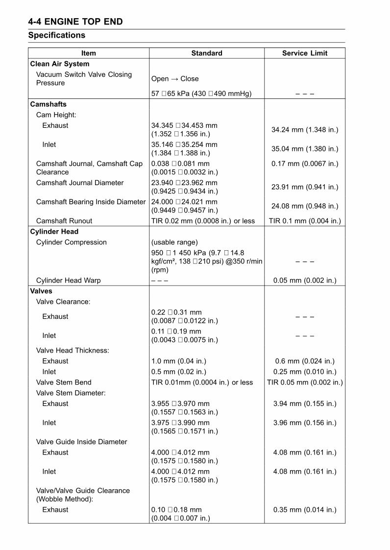
4-4 ENGINE TOP ENDSpecifications
Item Standard Service LimitClean Air SystemVacuum Switch Valve ClosingPressure Open → Close
57 ∼ 65 kPa (430 ∼ 490 mmHg) – – –CamshaftsCam Height:Exhaust 34.345 ∼ 34.453 mm
(1.352 ∼ 1.356 in.) 34.24 mm (1.348 in.)
Inlet 35.146 ∼ 35.254 mm(1.384 ∼ 1.388 in.) 35.04 mm (1.380 in.)
Camshaft Journal, Camshaft CapClearance
0.038 ∼ 0.081 mm(0.0015 ∼ 0.0032 in.)
0.17 mm (0.0067 in.)
Camshaft Journal Diameter 23.940 ∼ 23.962 mm(0.9425 ∼ 0.9434 in.) 23.91 mm (0.941 in.)
Camshaft Bearing Inside Diameter 24.000 ∼ 24.021 mm(0.9449 ∼ 0.9457 in.) 24.08 mm (0.948 in.)
Camshaft Runout TIR 0.02 mm (0.0008 in.) or less TIR 0.1 mm (0.004 in.)Cylinder HeadCylinder Compression (usable range)
950 ∼ 1 450 kPa (9.7 ∼ 14.8kgf/cm², 138 ∼ 210 psi) @350 r/min(rpm)
– – –
Cylinder Head Warp – – – 0.05 mm (0.002 in.)ValvesValve Clearance:
Exhaust 0.22 ∼ 0.31 mm(0.0087 ∼ 0.0122 in.) – – –
Inlet 0.11 ∼ 0.19 mm(0.0043 ∼ 0.0075 in.) – – –
Valve Head Thickness:Exhaust 1.0 mm (0.04 in.) 0.6 mm (0.024 in.)Inlet 0.5 mm (0.02 in.) 0.25 mm (0.010 in.)
Valve Stem Bend TIR 0.01mm (0.0004 in.) or less TIR 0.05 mm (0.002 in.)Valve Stem Diameter:Exhaust 3.955 ∼ 3.970 mm
(0.1557 ∼ 0.1563 in.)3.94 mm (0.155 in.)
Inlet 3.975 ∼ 3.990 mm(0.1565 ∼ 0.1571 in.)
3.96 mm (0.156 in.)
Valve Guide Inside DiameterExhaust 4.000 ∼ 4.012 mm
(0.1575 ∼ 0.1580 in.)4.08 mm (0.161 in.)
Inlet 4.000 ∼ 4.012 mm(0.1575 ∼ 0.1580 in.)
4.08 mm (0.161 in.)
Valve/Valve Guide Clearance(Wobble Method):Exhaust 0.10 ∼ 0.18 mm
(0.004 ∼ 0.007 in.)0.35 mm (0.014 in.)
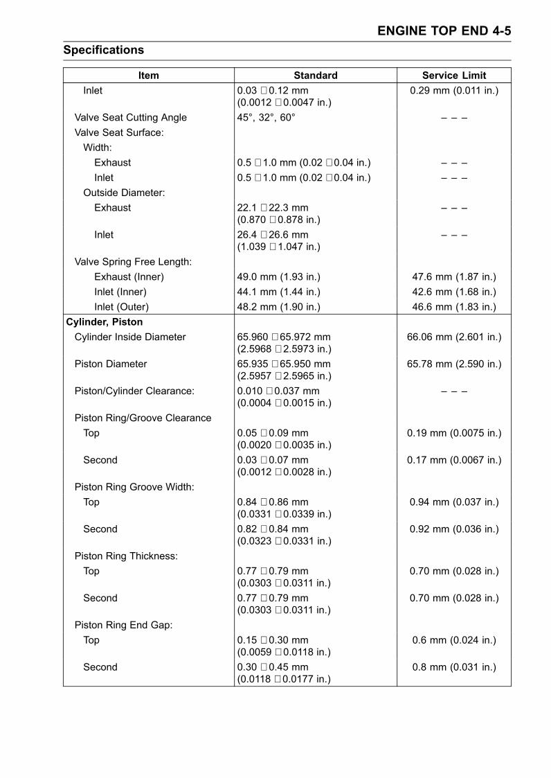
ENGINE TOP END 4-5Specifications
Item Standard Service LimitInlet 0.03 ∼ 0.12 mm
(0.0012 ∼ 0.0047 in.)0.29 mm (0.011 in.)
Valve Seat Cutting Angle 45°, 32°, 60° – – –Valve Seat Surface:Width:Exhaust 0.5 ∼ 1.0 mm (0.02 ∼ 0.04 in.) – – –Inlet 0.5 ∼ 1.0 mm (0.02 ∼ 0.04 in.) – – –
Outside Diameter:Exhaust 22.1 ∼ 22.3 mm
(0.870 ∼ 0.878 in.)– – –
Inlet 26.4 ∼ 26.6 mm(1.039 ∼ 1.047 in.)
– – –
Valve Spring Free Length:Exhaust (Inner) 49.0 mm (1.93 in.) 47.6 mm (1.87 in.)Inlet (Inner) 44.1 mm (1.44 in.) 42.6 mm (1.68 in.)Inlet (Outer) 48.2 mm (1.90 in.) 46.6 mm (1.83 in.)
Cylinder, PistonCylinder Inside Diameter 65.960 ∼ 65.972 mm
(2.5968 ∼ 2.5973 in.)66.06 mm (2.601 in.)
Piston Diameter 65.935 ∼ 65.950 mm(2.5957 ∼ 2.5965 in.)
65.78 mm (2.590 in.)
Piston/Cylinder Clearance: 0.010 ∼ 0.037 mm(0.0004 ∼ 0.0015 in.)
– – –
Piston Ring/Groove ClearanceTop 0.05 ∼ 0.09 mm
(0.0020 ∼ 0.0035 in.)0.19 mm (0.0075 in.)
Second 0.03 ∼ 0.07 mm(0.0012 ∼ 0.0028 in.)
0.17 mm (0.0067 in.)
Piston Ring Groove Width:Top 0.84 ∼ 0.86 mm
(0.0331 ∼ 0.0339 in.)0.94 mm (0.037 in.)
Second 0.82 ∼ 0.84 mm(0.0323 ∼ 0.0331 in.)
0.92 mm (0.036 in.)
Piston Ring Thickness:Top 0.77 ∼ 0.79 mm
(0.0303 ∼ 0.0311 in.)0.70 mm (0.028 in.)
Second 0.77 ∼ 0.79 mm(0.0303 ∼ 0.0311 in.)
0.70 mm (0.028 in.)
Piston Ring End Gap:Top 0.15 ∼ 0.30 mm
(0.0059 ∼ 0.0118 in.)0.6 mm (0.024 in.)
Second 0.30 ∼ 0.45 mm(0.0118 ∼ 0.0177 in.)
0.8 mm (0.031 in.)
4-6 ENGINE TOP ENDSpecifications
Special Tools - Compression Gauge, 20 kgf/cm²: 57001-221Valve Spring Compressor Assembly: 57001-241Piston Pin Puller Assembly: 57001-910Valve Seat Cutter, 45° - 27.5: 57001-1114Valve Seat Cutter, 45° - 32: 57001-1115Valve Seat Cutter, 32° - 28: 57001-1119Valve Seat Cutter, 32° - 30: 57001-1120Valve Seat Cutter, 60° - 30: 57001-1123Valve Seat Cutter Holder Bar: 57001-1128Valve Spring Compressor Adapter, 20: 57001-1154Valve Spring Compressor Adapter, 22: 57001-1202Spark Plug Wrench, Hex 16: 57001-1262Valve Guide Arbor, 4: 57001-1273Valve Guide Reamer, 4: 57001-1274Valve Seat Cutter Holder, 4: 57001-1275Fork Oil Level Gauge: 57001-1290Compression Gauge Adapter, M10 × 1.0: 57001-1317Valve Seat Cutter, 60° - 33: 57001-1334
Sealant - Kawasaki Bond (Silicone Sealant): 56019-120
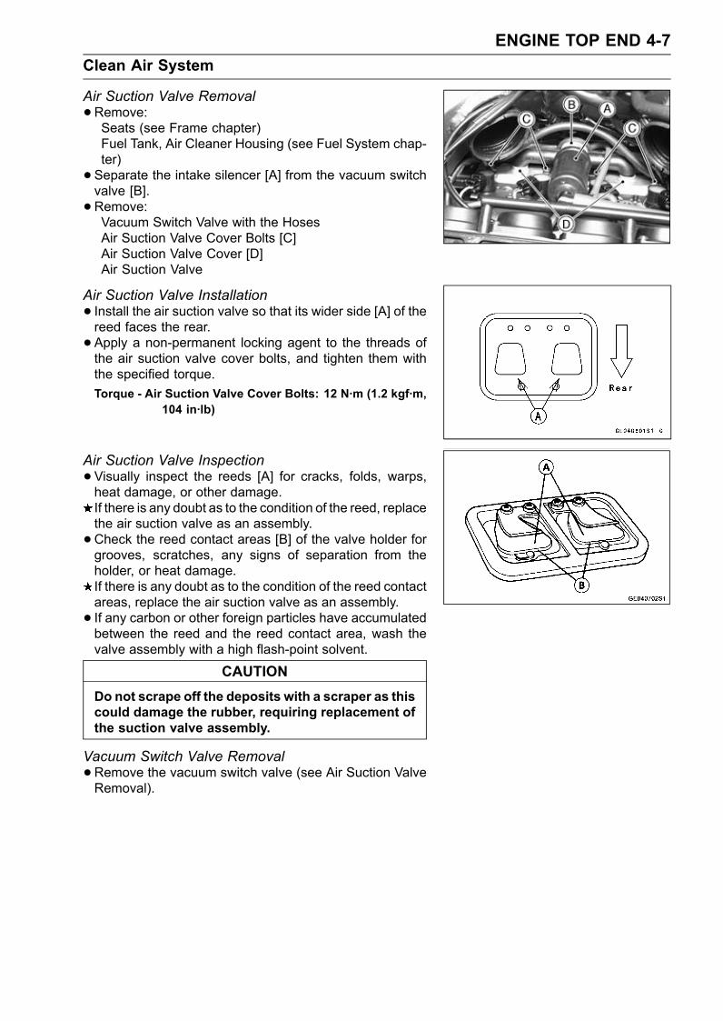
ENGINE TOP END 4-7Clean Air System
Air Suction Valve Removal•Remove:Seats (see Frame chapter)Fuel Tank, Air Cleaner Housing (see Fuel System chap-ter)• Separate the intake silencer [A] from the vacuum switchvalve [B].• Remove:Vacuum Switch Valve with the HosesAir Suction Valve Cover Bolts [C]Air Suction Valve Cover [D]Air Suction Valve
Air Suction Valve Installation• Install the air suction valve so that its wider side [A] of thereed faces the rear.• Apply a non-permanent locking agent to the threads ofthe air suction valve cover bolts, and tighten them withthe specified torque.Torque - Air Suction Valve Cover Bolts: 12 N·m (1.2 kgf·m,
104 in·lb)
Air Suction Valve Inspection•Visually inspect the reeds [A] for cracks, folds, warps,heat damage, or other damage.If there is any doubt as to the condition of the reed, replacethe air suction valve as an assembly.•Check the reed contact areas [B] of the valve holder forgrooves, scratches, any signs of separation from theholder, or heat damage.If there is any doubt as to the condition of the reed contactareas, replace the air suction valve as an assembly.• If any carbon or other foreign particles have accumulatedbetween the reed and the reed contact area, wash thevalve assembly with a high flash-point solvent.
CAUTIONDo not scrape off the deposits with a scraper as thiscould damage the rubber, requiring replacement ofthe suction valve assembly.
Vacuum Switch Valve Removal•Remove the vacuum switch valve (see Air Suction ValveRemoval).
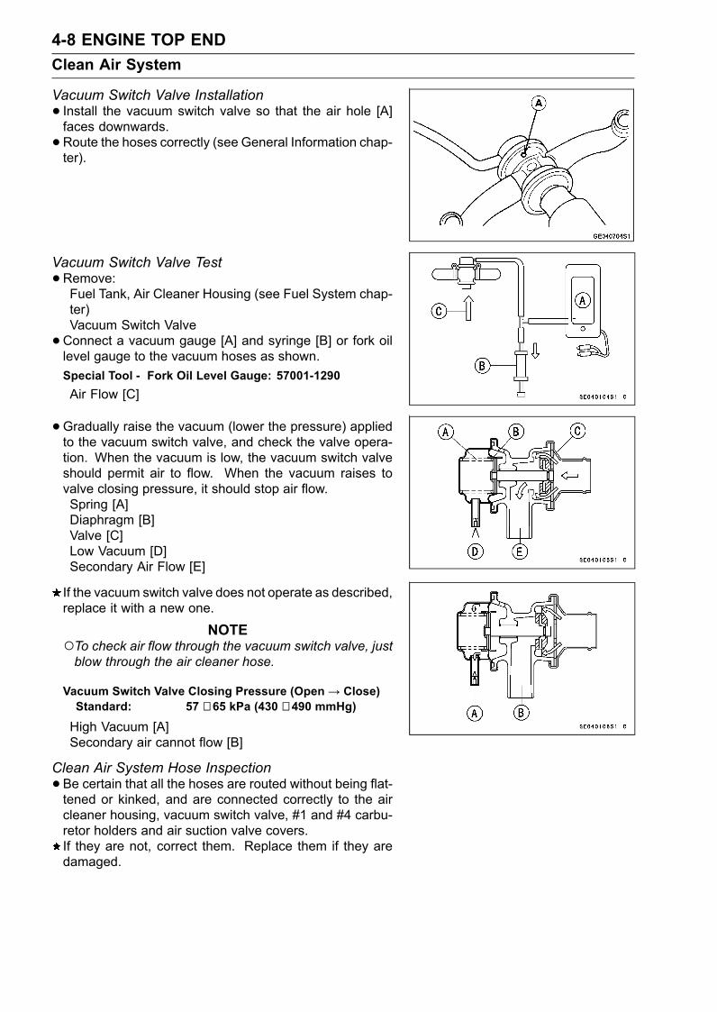
4-8 ENGINE TOP ENDClean Air System
Vacuum Switch Valve Installation• Install the vacuum switch valve so that the air hole [A]faces downwards.•Route the hoses correctly (see General Information chap-ter).
Vacuum Switch Valve Test•Remove:Fuel Tank, Air Cleaner Housing (see Fuel System chap-ter)Vacuum Switch Valve•Connect a vacuum gauge [A] and syringe [B] or fork oillevel gauge to the vacuum hoses as shown.Special Tool - Fork Oil Level Gauge: 57001-1290Air Flow [C]
•Gradually raise the vacuum (lower the pressure) appliedto the vacuum switch valve, and check the valve opera-tion. When the vacuum is low, the vacuum switch valveshould permit air to flow. When the vacuum raises tovalve closing pressure, it should stop air flow.Spring [A]Diaphragm [B]Valve [C]Low Vacuum [D]Secondary Air Flow [E]
If the vacuum switch valve does not operate as described,replace it with a new one.
NOTETo check air flow through the vacuum switch valve, justblow through the air cleaner hose.
Vacuum Switch Valve Closing Pressure (Open→ Close)Standard: 57 ∼ 65 kPa (430 ∼ 490 mmHg)
High Vacuum [A]Secondary air cannot flow [B]
Clean Air System Hose Inspection•Be certain that all the hoses are routed without being flat-tened or kinked, and are connected correctly to the aircleaner housing, vacuum switch valve, #1 and #4 carbu-retor holders and air suction valve covers.If they are not, correct them. Replace them if they aredamaged.
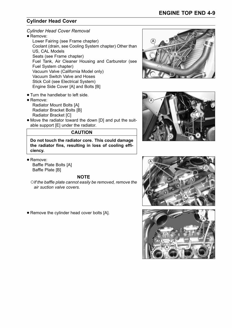
ENGINE TOP END 4-9Cylinder Head Cover
Cylinder Head Cover Removal•Remove:Lower Fairing (see Frame chapter)Coolant (drain, see Cooling System chapter) Other thanUS, CAL ModelsSeats (see Frame chapter)Fuel Tank, Air Cleaner Housing and Carburetor (seeFuel System chapter)Vacuum Valve (California Model only)Vacuum Switch Valve and HosesStick Coil (see Electrical System)Engine Side Cover [A] and Bolts [B]
• Turn the handlebar to left side.•Remove:Radiator Mount Bolts [A]Radiator Bracket Bolts [B]Radiator Bracket [C]•Move the radiator toward the down [D] and put the suit-able support [E] under the radiator.
CAUTIONDo not touch the radiator core. This could damagethe radiator fins, resulting in loss of cooling effi-ciency.
•Remove:Baffle Plate Bolts [A]Baffle Plate [B]
NOTEIf the baffle plate cannot easily be removed, remove theair suction valve covers.
•Remove the cylinder head cover bolts [A].
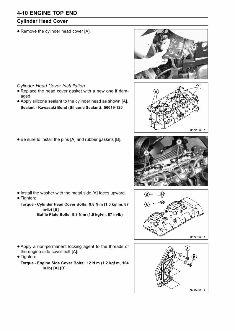
4-10 ENGINE TOP ENDCylinder Head Cover
•Remove the cylinder head cover [A].
Cylinder Head Cover Installation•Replace the head cover gasket with a new one if dam-aged.• Apply silicone sealant to the cylinder head as shown [A].Sealant - Kawasaki Bond (Silicone Sealant): 56019-120
•Be sure to install the pins [A] and rubber gaskets [B].
• Install the washer with the metal side [A] faces upward.• Tighten:Torque - Cylinder Head Cover Bolts: 9.8 N·m (1.0 kgf·m, 87
in·lb) [B]Baffle Plate Bolts: 9.8 N·m (1.0 kgf·m, 87 in·lb)
•Apply a non-permanent locking agent to the threads ofthe engine side cover bolt [A].• Tighten:Torque - Engine Side Cover Bolts: 12 N·m (1.2 kgf·m, 104
in·lb) [A] [B]
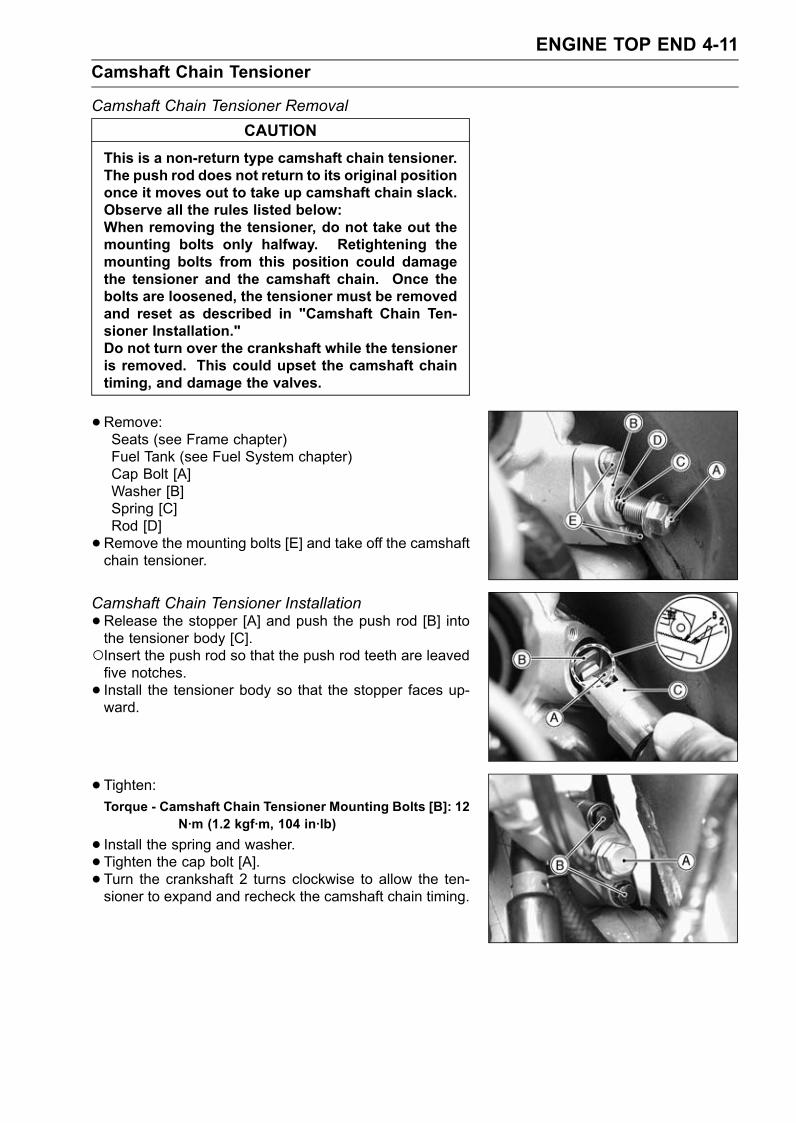
ENGINE TOP END 4-11Camshaft Chain Tensioner
Camshaft Chain Tensioner RemovalCAUTION
This is a non-return type camshaft chain tensioner.The push rod does not return to its original positiononce it moves out to take up camshaft chain slack.Observe all the rules listed below:When removing the tensioner, do not take out themounting bolts only halfway. Retightening themounting bolts from this position could damagethe tensioner and the camshaft chain. Once thebolts are loosened, the tensioner must be removedand reset as described in "Camshaft Chain Ten-sioner Installation."Do not turn over the crankshaft while the tensioneris removed. This could upset the camshaft chaintiming, and damage the valves.
•Remove:Seats (see Frame chapter)Fuel Tank (see Fuel System chapter)Cap Bolt [A]Washer [B]Spring [C]Rod [D]•Remove the mounting bolts [E] and take off the camshaftchain tensioner.
Camshaft Chain Tensioner Installation•Release the stopper [A] and push the push rod [B] intothe tensioner body [C].Insert the push rod so that the push rod teeth are leavedfive notches.• Install the tensioner body so that the stopper faces up-ward.
• Tighten:Torque - Camshaft Chain Tensioner Mounting Bolts [B]: 12
N·m (1.2 kgf·m, 104 in·lb)
• Install the spring and washer.• Tighten the cap bolt [A].• Turn the crankshaft 2 turns clockwise to allow the ten-sioner to expand and recheck the camshaft chain timing.
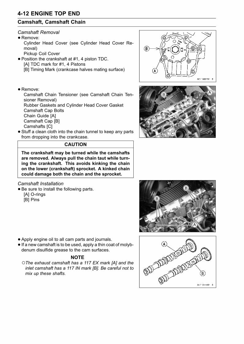
4-12 ENGINE TOP ENDCamshaft, Camshaft Chain
Camshaft Removal•Remove:Cylinder Head Cover (see Cylinder Head Cover Re-moval)Pickup Coil Cover• Position the crankshaft at #1, 4 piston TDC.[A] TDC mark for #1, 4 Pistons[B] Timing Mark (crankcase halves mating surface)
•Remove:Camshaft Chain Tensioner (see Camshaft Chain Ten-sioner Removal)Rubber Gaskets and Cylinder Head Cover GasketCamshaft Cap BoltsChain Guide [A]Camshaft Cap [B]Camshafts [C]• Stuff a clean cloth into the chain tunnel to keep any partsfrom dropping into the crankcase.
CAUTIONThe crankshaft may be turned while the camshaftsare removed. Always pull the chain taut while turn-ing the crankshaft. This avoids kinking the chainon the lower (crankshaft) sprocket. A kinked chaincould damage both the chain and the sprocket.
Camshaft Installation•Be sure to install the following parts.[A] O-rings[B] Pins
•Apply engine oil to all cam parts and journals.• If a new camshaft is to be used, apply a thin coat of molyb-denum disulfide grease to the cam surfaces.
NOTEThe exhaust camshaft has a 117 EX mark [A] and theinlet camshaft has a 117 IN mark [B]. Be careful not tomix up these shafts.
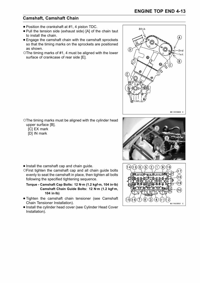
ENGINE TOP END 4-13Camshaft, Camshaft Chain
•Position the crankshaft at #1, 4 piston TDC.•Pull the tension side (exhaust side) [A] of the chain tautto install the chain.• Engage the camshaft chain with the camshaft sprocketsso that the timing marks on the sprockets are positionedas shown.The timing marks of #1, 4 must be aligned with the lowersurface of crankcase of rear side [E].
The timing marks must be aligned with the cylinder headupper surface [B].[C] EX mark[D] IN mark
• Install the camshaft cap and chain guide.First tighten the camshaft cap and all chain guide boltsevenly to seat the camshaft in place, then tighten all boltsfollowing the specified tightening sequence.Torque - Camshaft Cap Bolts: 12 N·m (1.2 kgf·m, 104 in·lb)
Camshaft Chain Guide Bolts: 12 N·m (1.2 kgf·m,104 in·lb)
•Tighten the camshaft chain tensioner (see CamshaftChain Tensioner Installation).• Install the cylinder head cover (see Cylinder Head CoverInstallation).
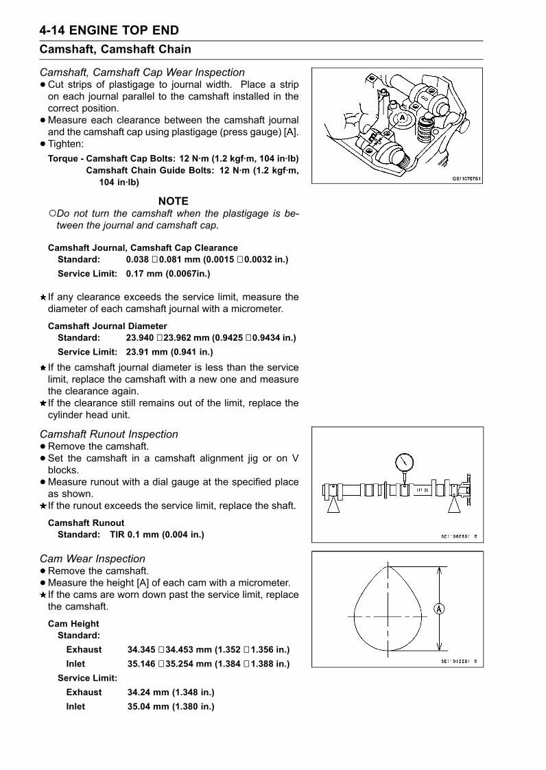
4-14 ENGINE TOP ENDCamshaft, Camshaft Chain
Camshaft, Camshaft Cap Wear Inspection•Cut strips of plastigage to journal width. Place a stripon each journal parallel to the camshaft installed in thecorrect position.•Measure each clearance between the camshaft journaland the camshaft cap using plastigage (press gauge) [A].• Tighten:Torque - Camshaft Cap Bolts: 12 N·m (1.2 kgf·m, 104 in·lb)
Camshaft Chain Guide Bolts: 12 N·m (1.2 kgf·m,104 in·lb)
NOTEDo not turn the camshaft when the plastigage is be-tween the journal and camshaft cap.
Camshaft Journal, Camshaft Cap ClearanceStandard: 0.038 ∼ 0.081 mm (0.0015 ∼ 0.0032 in.)Service Limit: 0.17 mm (0.0067in.)
If any clearance exceeds the service limit, measure thediameter of each camshaft journal with a micrometer.
Camshaft Journal DiameterStandard: 23.940 ∼ 23.962 mm (0.9425 ∼ 0.9434 in.)Service Limit: 23.91 mm (0.941 in.)
If the camshaft journal diameter is less than the servicelimit, replace the camshaft with a new one and measurethe clearance again.If the clearance still remains out of the limit, replace thecylinder head unit.
Camshaft Runout Inspection•Remove the camshaft.• Set the camshaft in a camshaft alignment jig or on Vblocks.•Measure runout with a dial gauge at the specified placeas shown.If the runout exceeds the service limit, replace the shaft.
Camshaft RunoutStandard: TIR 0.1 mm (0.004 in.)
Cam Wear Inspection•Remove the camshaft.•Measure the height [A] of each cam with a micrometer.If the cams are worn down past the service limit, replacethe camshaft.
Cam HeightStandard:Exhaust 34.345 ∼ 34.453 mm (1.352 ∼ 1.356 in.)Inlet 35.146 ∼ 35.254 mm (1.384 ∼ 1.388 in.)
Service Limit:Exhaust 34.24 mm (1.348 in.)Inlet 35.04 mm (1.380 in.)
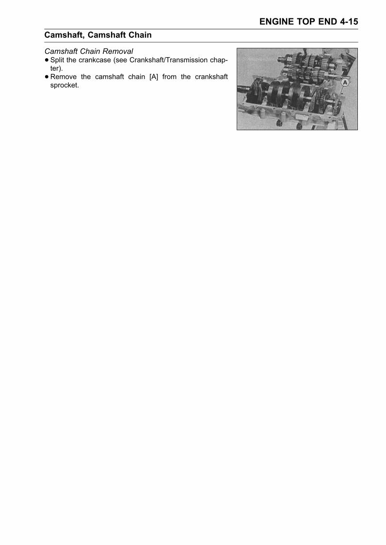
ENGINE TOP END 4-15Camshaft, Camshaft Chain
Camshaft Chain Removal•Split the crankcase (see Crankshaft/Transmission chap-ter).• Remove the camshaft chain [A] from the crankshaftsprocket.
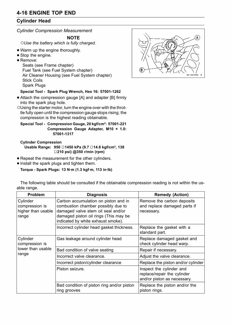
4-16 ENGINE TOP ENDCylinder Head
Cylinder Compression MeasurementNOTE
Use the battery which is fully charged.•Warm up the engine thoroughly.• Stop the engine.•Remove:Seats (see Frame chapter)Fuel Tank (see Fuel System chapter)Air Cleaner Housing (see Fuel System chapter)Stick CoilsSpark PlugsSpecial Tool - Spark Plug Wrench, Hex 16: 57001-1262
•Attach the compression gauge [A] and adapter [B] firmlyinto the spark plug hole.Using the starter motor, turn the engine over with the throt-tle fully open until the compression gauge stops rising; thecompression is the highest reading obtainable.Special Tool - Compression Gauge, 20 kgf/cm²: 57001-221
Compression Gauge Adapter, M10 × 1.0:57001-1317
Cylinder CompressionUsable Range: 950 ∼ 1450 kPa (9.7 ∼ 14.8 kgf/cm², 138
∼ 210 psi) @350 r/min (rpm)
•Repeat the measurement for the other cylinders.• Install the spark plugs and tighten them.Torque - Spark Plugs: 13 N·m (1.3 kgf·m, 113 in·lb)
The following table should be consulted if the obtainable compression reading is not within the us-able range.
Problem Diagnosis Remedy (Action)Carbon accumulation on piston and incombustion chamber possibly due todamaged valve stem oil seal and/ordamaged piston oil rings (This may beindicated by white exhaust smoke).
Remove the carbon depositsand replace damaged parts ifnecessary.
Cylindercompression ishigher than usablerange
Incorrect cylinder head gasket thickness. Replace the gasket with astandard part.
Gas leakage around cylinder head Replace damaged gasket andcheck cylinder head warp.
Bad condition of valve seating Repair if necessary.
Cylindercompression islower than usablerange Incorrect valve clearance. Adjust the valve clearance.
Incorrect piston/cylinder clearance Replace the piston and/or cylinderPiston seizure. Inspect the cylinder and
replace/repair the cylinderand/or piston as necessary.
Bad condition of piston ring and/or pistonring grooves
Replace the piston and/or thepiston rings.
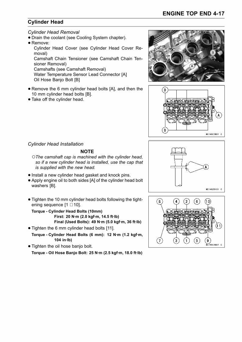
ENGINE TOP END 4-17Cylinder Head
Cylinder Head Removal•Drain the coolant (see Cooling System chapter).• Remove:Cylinder Head Cover (see Cylinder Head Cover Re-moval)Camshaft Chain Tensioner (see Camshaft Chain Ten-sioner Removal)Camshafts (see Camshaft Removal)Water Temperature Sensor Lead Connector [A]Oil Hose Banjo Bolt [B]
•Remove the 6 mm cylinder head bolts [A], and then the10 mm cylinder head bolts [B].• Take off the cylinder head.
Cylinder Head InstallationNOTE
The camshaft cap is machined with the cylinder head,so if a new cylinder head is installed, use the cap thatis supplied with the new head.
• Install a new cylinder head gasket and knock pins.• Apply engine oil to both sides [A] of the cylinder head boltwashers [B].
• Tighten the 10 mm cylinder head bolts following the tight-ening sequence [1 ∼ 10].Torque - Cylinder Head Bolts (10mm)
First: 20 N·m (2.0 kgf·m, 14.5 ft·lb)Final (Used Bolts): 49 N·m (5.0 kgf·m, 36 ft·lb)
•Tighten the 6 mm cylinder head bolts [11].Torque - Cylinder Head Bolts (6 mm): 12 N·m (1.2 kgf·m,
104 in·lb)
•Tighten the oil hose banjo bolt.Torque - Oil Hose Banjo Bolt: 25 N·m (2.5 kgf·m, 18.0 ft·lb)
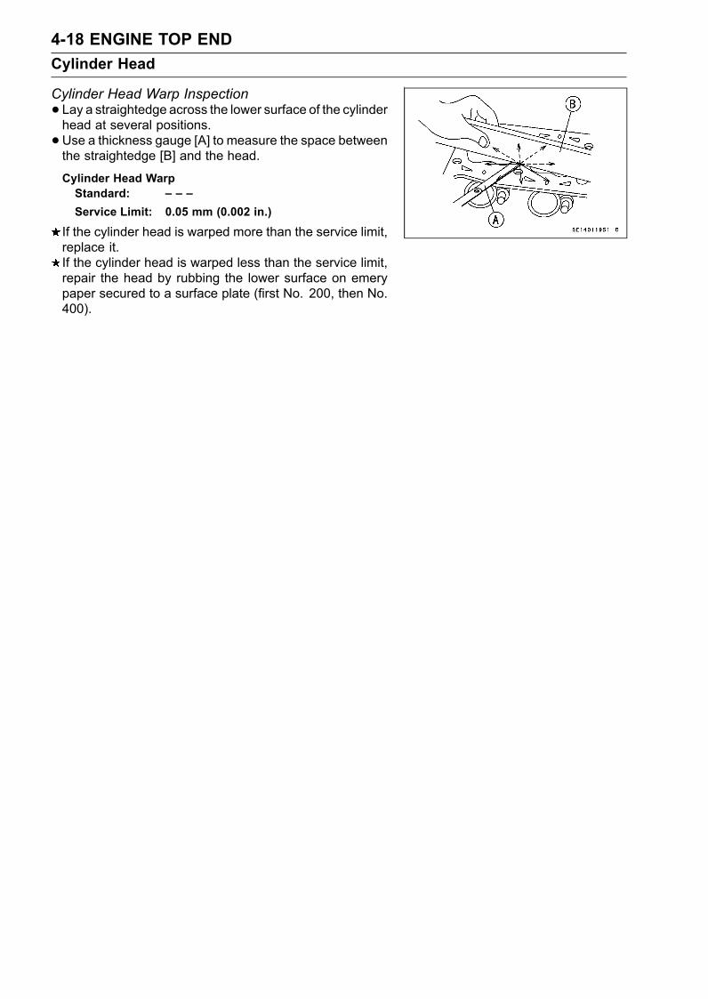
4-18 ENGINE TOP ENDCylinder Head
Cylinder Head Warp Inspection• Lay a straightedge across the lower surface of the cylinderhead at several positions.•Use a thickness gauge [A] to measure the space betweenthe straightedge [B] and the head.
Cylinder Head WarpStandard: – – –Service Limit: 0.05 mm (0.002 in.)
If the cylinder head is warped more than the service limit,replace it.If the cylinder head is warped less than the service limit,repair the head by rubbing the lower surface on emerypaper secured to a surface plate (first No. 200, then No.400).
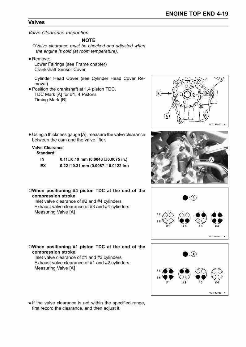
ENGINE TOP END 4-19Valves
Valve Clearance InspectionNOTE
Valve clearance must be checked and adjusted whenthe engine is cold (at room temperature).
•Remove:Lower Fairings (see Frame chapter)Crankshaft Sensor Cover
Cylinder Head Cover (see Cylinder Head Cover Re-moval)• Position the crankshaft at 1,4 piston TDC.TDC Mark [A] for #1, 4 PistonsTiming Mark [B]
•Using a thickness gauge [A], measure the valve clearancebetween the cam and the valve lifter.
Valve ClearanceStandard:IN 0.11∼ 0.19 mm (0.0043 ∼ 0.0075 in.)EX 0.22 ∼ 0.31 mm (0.0087 ∼ 0.0122 in.)
When positioning #4 piston TDC at the end of thecompression stroke:Inlet valve clearance of #2 and #4 cylindersExhaust valve clearance of #3 and #4 cylindersMeasuring Valve [A]
When positioning #1 piston TDC at the end of thecompression stroke:Inlet valve clearance of #1 and #3 cylindersExhaust valve clearance of #1 and #2 cylindersMeasuring Valve [A]
If the valve clearance is not within the specified range,first record the clearance, and then adjust it.
4-20 ENGINE TOP ENDValves
Valve Clearance Adjustment•To change the valve clearance, remove the camshaftchain tensioner, camshafts and valve lifters. Replace theshim with one of a different thickness.
NOTEMark and record the valve lifter and shim locations sothey can be reinstalled in their original positions.If there is no clearance, select a shim which is severalsizes smaller and then measure the clearance.
•To select a new shim which brings the valve clearancewithin the specified range, refer to the Valve ClearanceAdjustment Charts.• Apply a thin coat of molybdenum disulfide grease to thevalve lifters.• Install the camshafts. Be sure to time the camshafts prop-erly (see Camshaft Installation).• Remeasure any valve clearance that was adjusted.Readjust if necessary.
CAUTIONDo not put shim stock under the shim. This maycause the shim to pop out at high rpm, causing ex-tensive engine damage.Do not grind the shim. This may cause it to fracture,causing extensive engine damage.
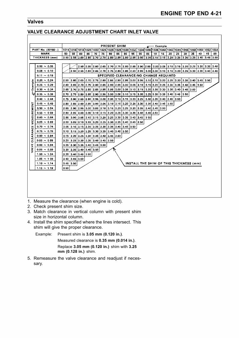
ENGINE TOP END 4-21Valves
VALVE CLEARANCE ADJUSTMENT CHART INLET VALVE
1. Measure the clearance (when engine is cold).2. Check present shim size.3. Match clearance in vertical column with present shimsize in horizontal column.
4. Install the shim specified where the lines intersect. Thisshim will give the proper clearance.Example: Present shim is 3.05 mm (0.120 in.).
Measured clearance is 0.35 mm (0.014 in.).Replace 3.05 mm (0.120 in.) shim with 3.25mm (0.128 in.) shim.
5. Remeasure the valve clearance and readjust if neces-sary.
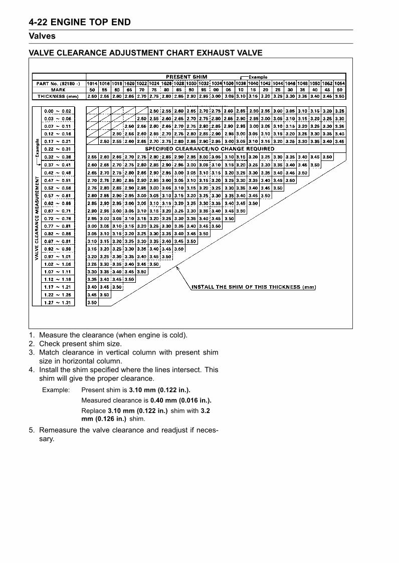
4-22 ENGINE TOP ENDValves
VALVE CLEARANCE ADJUSTMENT CHART EXHAUST VALVE
1. Measure the clearance (when engine is cold).2. Check present shim size.3. Match clearance in vertical column with present shimsize in horizontal column.
4. Install the shim specified where the lines intersect. Thisshim will give the proper clearance.Example: Present shim is 3.10 mm (0.122 in.).
Measured clearance is 0.40 mm (0.016 in.).Replace 3.10 mm (0.122 in.) shim with 3.2mm (0.126 in.) shim.
5. Remeasure the valve clearance and readjust if neces-sary.
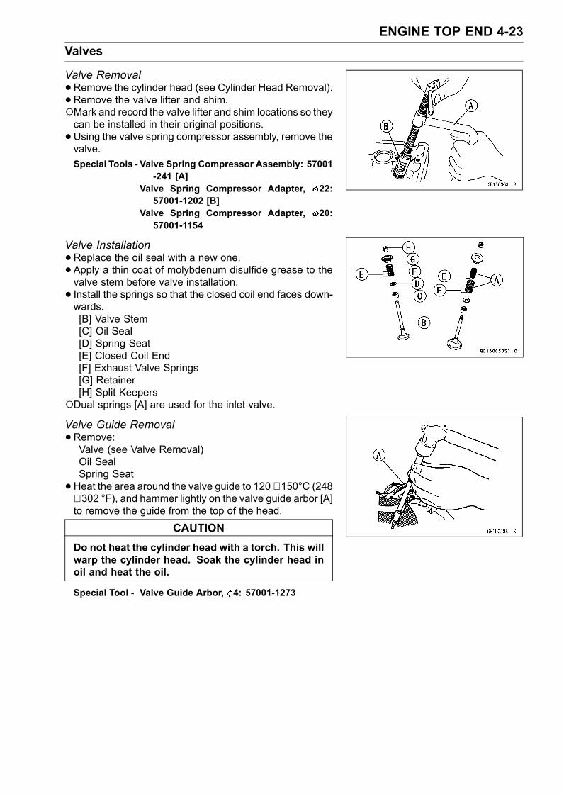
ENGINE TOP END 4-23Valves
Valve Removal•Remove the cylinder head (see Cylinder Head Removal).• Remove the valve lifter and shim.Mark and record the valve lifter and shim locations so theycan be installed in their original positions.•Using the valve spring compressor assembly, remove thevalve.Special Tools - Valve Spring Compressor Assembly: 57001
-241 [A]Valve Spring Compressor Adapter, 22:57001-1202 [B]
Valve Spring Compressor Adapter, 20:57001-1154
Valve Installation•Replace the oil seal with a new one.• Apply a thin coat of molybdenum disulfide grease to thevalve stem before valve installation.• Install the springs so that the closed coil end faces down-wards.[B] Valve Stem[C] Oil Seal[D] Spring Seat[E] Closed Coil End[F] Exhaust Valve Springs[G] Retainer[H] Split Keepers
Dual springs [A] are used for the inlet valve.Valve Guide Removal•Remove:Valve (see Valve Removal)Oil SealSpring Seat•Heat the area around the valve guide to 120 ∼ 150°C (248
∼ 302 °F), and hammer lightly on the valve guide arbor [A]to remove the guide from the top of the head.
CAUTIONDo not heat the cylinder head with a torch. This willwarp the cylinder head. Soak the cylinder head inoil and heat the oil.
Special Tool - Valve Guide Arbor, 4: 57001-1273
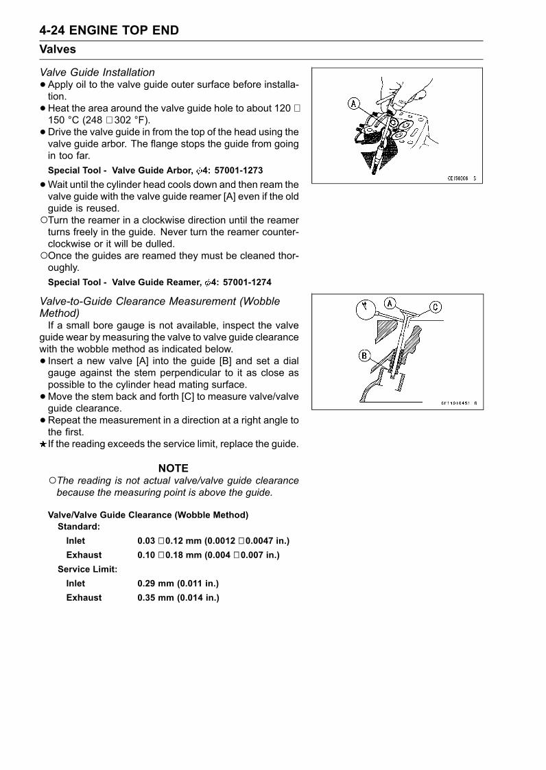
4-24 ENGINE TOP ENDValves
Valve Guide Installation•Apply oil to the valve guide outer surface before installa-tion.•Heat the area around the valve guide hole to about 120 ∼150 °C (248 ∼ 302 °F).•Drive the valve guide in from the top of the head using thevalve guide arbor. The flange stops the guide from goingin too far.Special Tool - Valve Guide Arbor, 4: 57001-1273
•Wait until the cylinder head cools down and then ream thevalve guide with the valve guide reamer [A] even if the oldguide is reused.Turn the reamer in a clockwise direction until the reamerturns freely in the guide. Never turn the reamer counter-clockwise or it will be dulled.Once the guides are reamed they must be cleaned thor-oughly.Special Tool - Valve Guide Reamer, 4: 57001-1274
Valve-to-Guide Clearance Measurement (WobbleMethod)If a small bore gauge is not available, inspect the valve
guide wear by measuring the valve to valve guide clearancewith the wobble method as indicated below.• Insert a new valve [A] into the guide [B] and set a dialgauge against the stem perpendicular to it as close aspossible to the cylinder head mating surface.•Move the stem back and forth [C] to measure valve/valveguide clearance.•Repeat the measurement in a direction at a right angle tothe first.If the reading exceeds the service limit, replace the guide.
NOTEThe reading is not actual valve/valve guide clearancebecause the measuring point is above the guide.
Valve/Valve Guide Clearance (Wobble Method)Standard:Inlet 0.03 ∼ 0.12 mm (0.0012 ∼ 0.0047 in.)Exhaust 0.10 ∼ 0.18 mm (0.004 ∼ 0.007 in.)
Service Limit:Inlet 0.29 mm (0.011 in.)Exhaust 0.35 mm (0.014 in.)
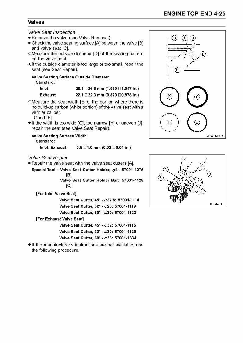
ENGINE TOP END 4-25Valves
Valve Seat Inspection•Remove the valve (see Valve Removal).• Check the valve seating surface [A] between the valve [B]and valve seat [C].Measure the outside diameter [D] of the seating patternon the valve seat.If the outside diameter is too large or too small, repair theseat (see Seat Repair).
Valve Seating Surface Outside DiameterStandard:Inlet 26.4 ∼ 26.6 mm (1.039 ∼ 1.047 in.)Exhaust 22.1 ∼ 22.3 mm (0.870 ∼ 0.878 in.)
Measure the seat width [E] of the portion where there isno build-up carbon (white portion) of the valve seat with avernier caliper.Good [F]If the width is too wide [G], too narrow [H] or uneven [J],repair the seat (see Valve Seat Repair).
Valve Seating Surface WidthStandard:Inlet, Exhaust 0.5 ∼ 1.0 mm (0.02 ∼ 0.04 in.)
Valve Seat Repair•Repair the valve seat with the valve seat cutters [A].Special Tool - Valve Seat Cutter Holder, 4: 57001-1275
[B]Valve Seat Cutter Holder Bar: 57001-1128[C]
[For Inlet Valve Seat]Valve Seat Cutter, 45° - 27.5: 57001-1114Valve Seat Cutter, 32° - 28: 57001-1119Valve Seat Cutter, 60° - 30: 57001-1123
[For Exhaust Valve Seat]Valve Seat Cutter, 45° - 32: 57001-1115Valve Seat Cutter, 32° - 30: 57001-1120Valve Seat Cutter, 60° - 33: 57001-1334
If the manufacturer’s instructions are not available, usethe following procedure.
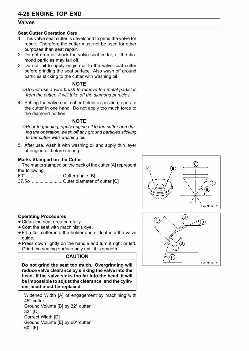
4-26 ENGINE TOP ENDValves
Seat Cutter Operation Care1. This valve seat cutter is developed to grind the valve forrepair. Therefore the cutter must not be used for otherpurposes than seat repair.
2. Do not drop or shock the valve seat cutter, or the dia-mond particles may fall off.
3. Do not fail to apply engine oil to the valve seat cutterbefore grinding the seat surface. Also wash off groundparticles sticking to the cutter with washing oil.
NOTEDo not use a wire brush to remove the metal particlesfrom the cutter. It will take off the diamond particles.
4. Setting the valve seat cutter holder in position, operatethe cutter in one hand. Do not apply too much force tothe diamond portion.
NOTEPrior to grinding, apply engine oil to the cutter and dur-ing the operation, wash off any ground particles stickingto the cutter with washing oil.
5. After use, wash it with washing oil and apply thin layerof engine oil before storing.
Marks Stamped on the CutterThemarks stamped on the back of the cutter [A] represent
the following.60° ........................... Cutter angle [B]37.5 ....................... Outer diameter of cutter [C]
Operating Procedures•Clean the seat area carefully.• Coat the seat with machinist’s dye.• Fit a 45° cutter into the holder and slide it into the valveguide.• Press down lightly on the handle and turn it right or left.Grind the seating surface only until it is smooth.
CAUTIONDo not grind the seat too much. Overgrinding willreduce valve clearance by sinking the valve into thehead. If the valve sinks too far into the head, it willbe impossible to adjust the clearance, and the cylin-der head must be replaced.
Widened Width [A] of engagement by machining with45° cutterGround Volume [B] by 32° cutter32° [C]Correct Width [D]Ground Volume [E] by 60° cutter60° [F]
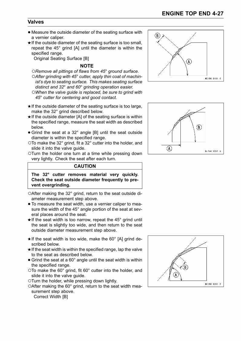
ENGINE TOP END 4-27Valves
•Measure the outside diameter of the seating surface witha vernier caliper.If the outside diameter of the seating surface is too small,repeat the 45° grind [A] until the diameter is within thespecified range.Original Seating Surface [B]
NOTERemove all pittings of flaws from 45° ground surface.After grinding with 45° cutter, apply thin coat of machin-ist’s dye to seating surface. This makes seating surfacedistinct and 32° and 60° grinding operation easier.When the valve guide is replaced, be sure to grind with45° cutter for centering and good contact.
If the outside diameter of the seating surface is too large,make the 32° grind described below.If the outside diameter [A] of the seating surface is withinthe specified range, measure the seat width as describedbelow.•Grind the seat at a 32° angle [B] until the seat outsidediameter is within the specified range.To make the 32° grind, fit a 32° cutter into the holder, andslide it into the valve guide.Turn the holder one turn at a time while pressing downvery lightly. Check the seat after each turn.
CAUTIONThe 32° cutter removes material very quickly.Check the seat outside diameter frequently to pre-vent overgrinding.
After making the 32° grind, return to the seat outside di-ameter measurement step above.• To measure the seat width, use a vernier caliper to mea-sure the width of the 45° angle portion of the seat at sev-eral places around the seat.If the seat width is too narrow, repeat the 45° grind untilthe seat is slightly too wide, and then return to the seatoutside diameter measurement step above.
If the seat width is too wide, make the 60° [A] grind de-scribed below.If the seat width is within the specified range, lap the valveto the seat as described below.•Grind the seat at a 60° angle until the seat width is withinthe specified range.To make the 60° grind, fit 60° cutter into the holder, andslide it into the valve guide.Turn the holder, while pressing down lightly.After making the 60° grind, return to the seat width mea-surement step above.Correct Width [B]
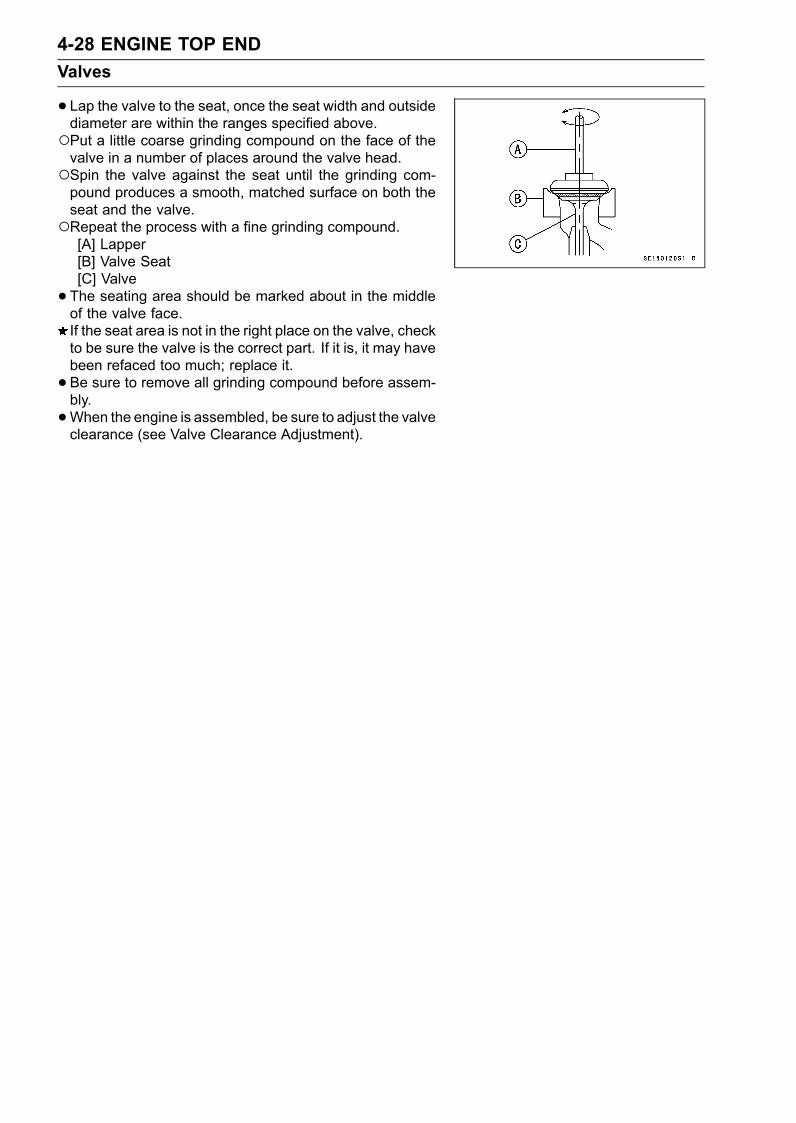
4-28 ENGINE TOP ENDValves
• Lap the valve to the seat, once the seat width and outsidediameter are within the ranges specified above.Put a little coarse grinding compound on the face of thevalve in a number of places around the valve head.Spin the valve against the seat until the grinding com-pound produces a smooth, matched surface on both theseat and the valve.Repeat the process with a fine grinding compound.[A] Lapper[B] Valve Seat[C] Valve• The seating area should be marked about in the middleof the valve face.If the seat area is not in the right place on the valve, checkto be sure the valve is the correct part. If it is, it may havebeen refaced too much; replace it.• Be sure to remove all grinding compound before assem-bly.•When the engine is assembled, be sure to adjust the valveclearance (see Valve Clearance Adjustment).
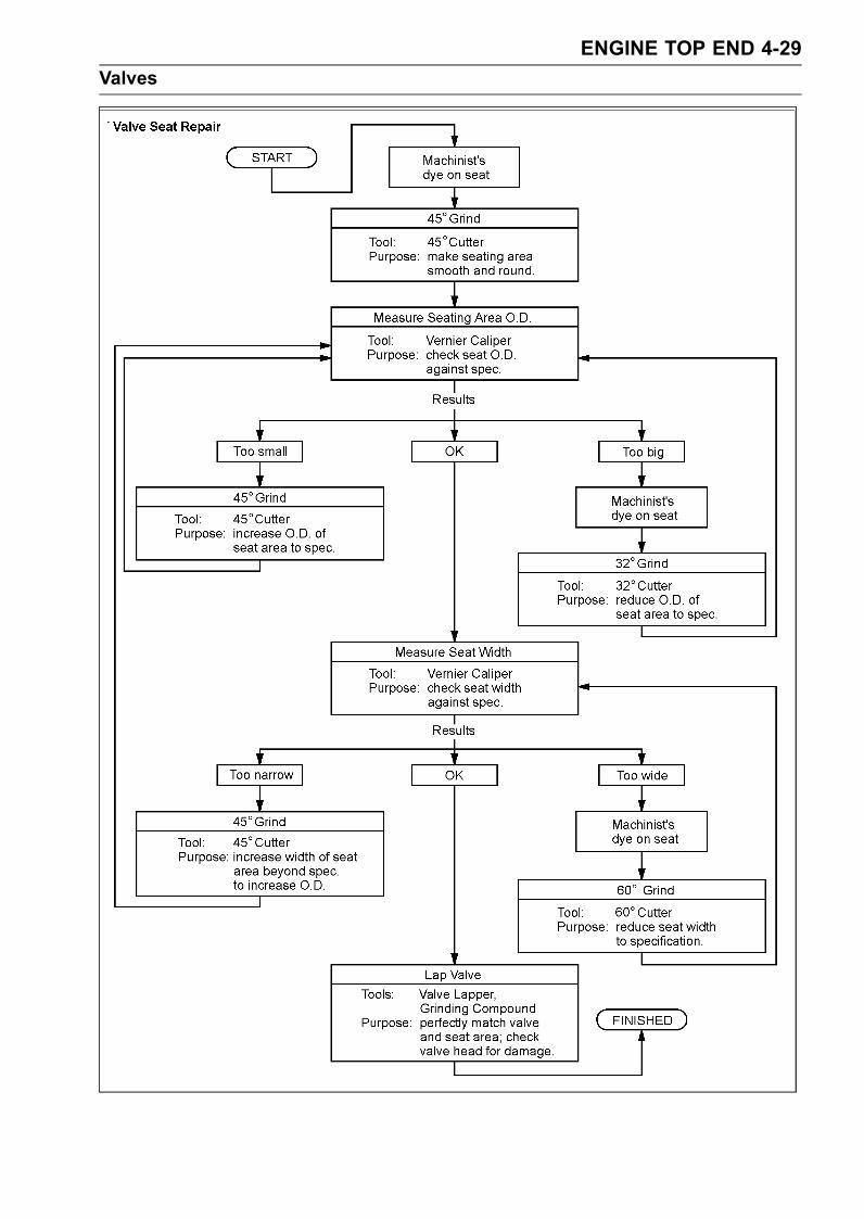
ENGINE TOP END 4-29Valves
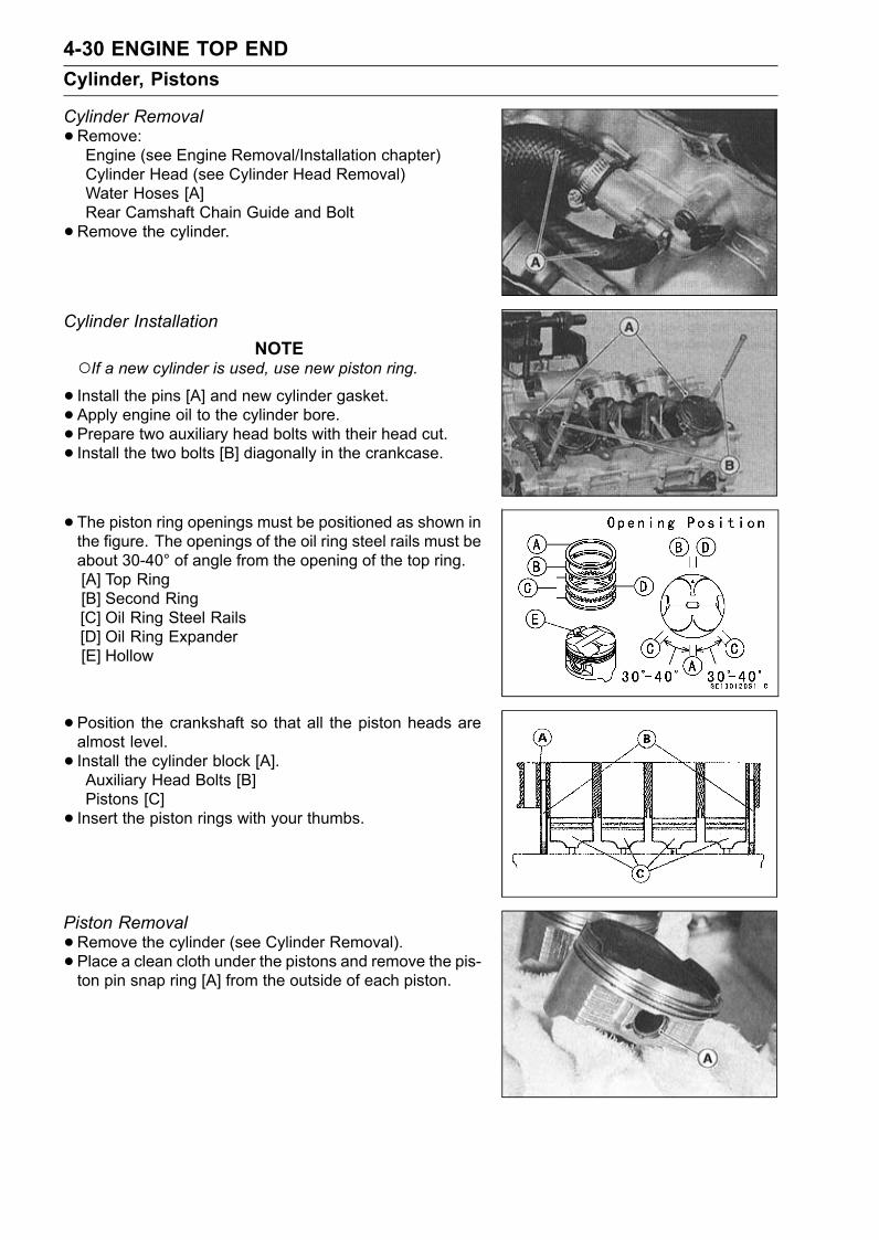
4-30 ENGINE TOP ENDCylinder, Pistons
Cylinder Removal•Remove:Engine (see Engine Removal/Installation chapter)Cylinder Head (see Cylinder Head Removal)Water Hoses [A]Rear Camshaft Chain Guide and Bolt• Remove the cylinder.
Cylinder InstallationNOTE
If a new cylinder is used, use new piston ring.• Install the pins [A] and new cylinder gasket.• Apply engine oil to the cylinder bore.• Prepare two auxiliary head bolts with their head cut.• Install the two bolts [B] diagonally in the crankcase.
• The piston ring openings must be positioned as shown inthe figure. The openings of the oil ring steel rails must beabout 30-40° of angle from the opening of the top ring.[A] Top Ring[B] Second Ring[C] Oil Ring Steel Rails[D] Oil Ring Expander[E] Hollow
•Position the crankshaft so that all the piston heads arealmost level.• Install the cylinder block [A].Auxiliary Head Bolts [B]Pistons [C]• Insert the piston rings with your thumbs.
Piston Removal•Remove the cylinder (see Cylinder Removal).• Place a clean cloth under the pistons and remove the pis-ton pin snap ring [A] from the outside of each piston.
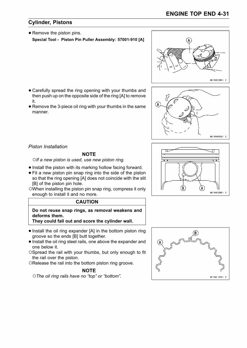
ENGINE TOP END 4-31Cylinder, Pistons
•Remove the piston pins.Special Tool - Piston Pin Puller Assembly: 57001-910 [A]
•Carefully spread the ring opening with your thumbs andthen push up on the opposite side of the ring [A] to removeit.• Remove the 3-piece oil ring with your thumbs in the samemanner.
Piston InstallationNOTE
If a new piston is used, use new piston ring.• Install the piston with its marking hollow facing forward.• Fit a new piston pin snap ring into the side of the pistonso that the ring opening [A] does not coincide with the slit[B] of the piston pin hole.When installing the piston pin snap ring, compress it onlyenough to install it and no more.
CAUTIONDo not reuse snap rings, as removal weakens anddeforms them.They could fall out and score the cylinder wall.
• Install the oil ring expander [A] in the bottom piston ringgroove so the ends [B] butt together.• Install the oil ring steel rails, one above the expander andone below it.Spread the rail with your thumbs, but only enough to fitthe rail over the piston.Release the rail into the bottom piston ring groove.
NOTEThe oil ring rails have no “top” or “bottom”.
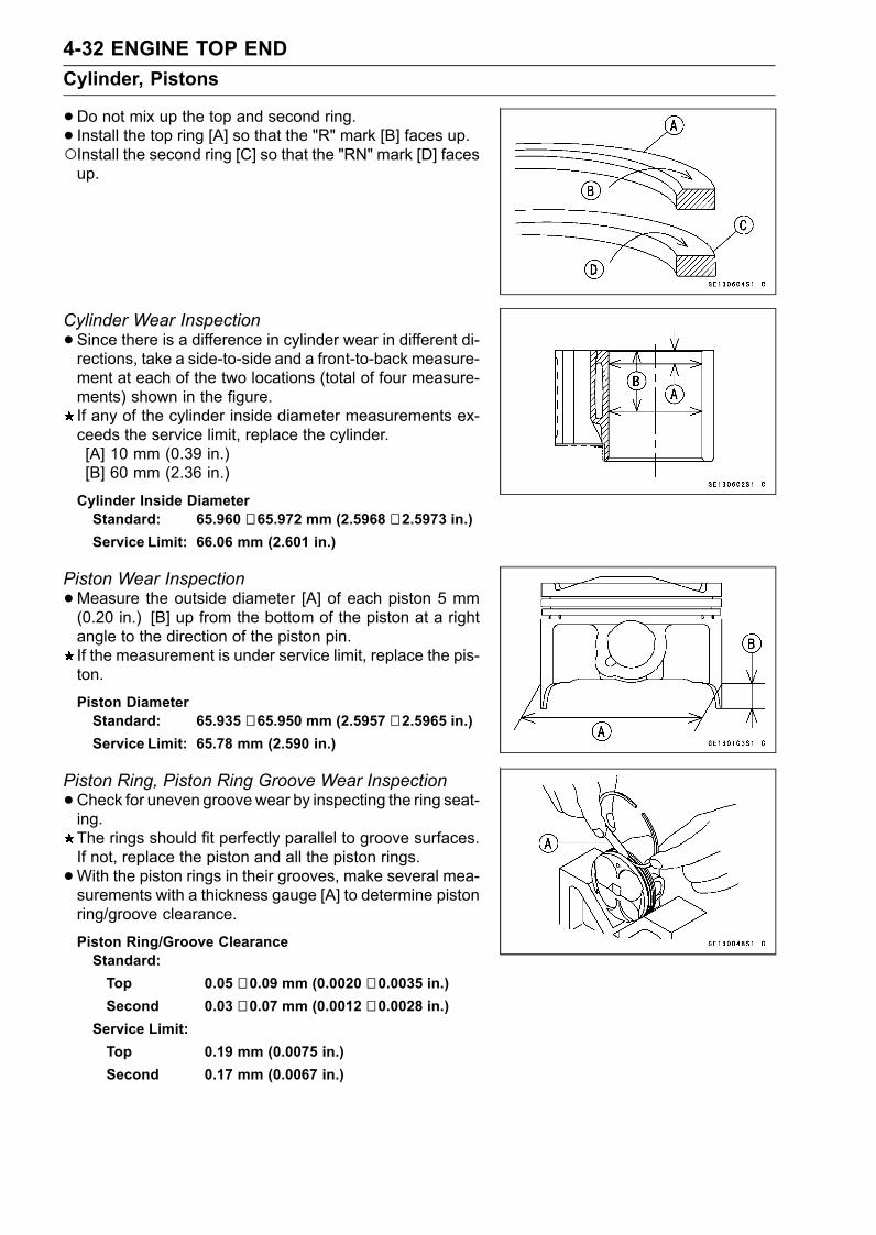
4-32 ENGINE TOP ENDCylinder, Pistons
•Do not mix up the top and second ring.• Install the top ring [A] so that the "R" mark [B] faces up.Install the second ring [C] so that the "RN" mark [D] facesup.
Cylinder Wear Inspection•Since there is a difference in cylinder wear in different di-rections, take a side-to-side and a front-to-back measure-ment at each of the two locations (total of four measure-ments) shown in the figure.If any of the cylinder inside diameter measurements ex-ceeds the service limit, replace the cylinder.[A] 10 mm (0.39 in.)[B] 60 mm (2.36 in.)
Cylinder Inside DiameterStandard: 65.960 ∼ 65.972 mm (2.5968 ∼ 2.5973 in.)Service Limit: 66.06 mm (2.601 in.)
Piston Wear Inspection•Measure the outside diameter [A] of each piston 5 mm(0.20 in.) [B] up from the bottom of the piston at a rightangle to the direction of the piston pin.If the measurement is under service limit, replace the pis-ton.
Piston DiameterStandard: 65.935 ∼ 65.950 mm (2.5957 ∼ 2.5965 in.)Service Limit: 65.78 mm (2.590 in.)
Piston Ring, Piston Ring Groove Wear Inspection•Check for uneven groovewear by inspecting the ring seat-ing.The rings should fit perfectly parallel to groove surfaces.If not, replace the piston and all the piston rings.•With the piston rings in their grooves, make several mea-surements with a thickness gauge [A] to determine pistonring/groove clearance.
Piston Ring/Groove ClearanceStandard:Top 0.05 ∼ 0.09 mm (0.0020 ∼ 0.0035 in.)Second 0.03 ∼ 0.07 mm (0.0012 ∼ 0.0028 in.)
Service Limit:Top 0.19 mm (0.0075 in.)Second 0.17 mm (0.0067 in.)
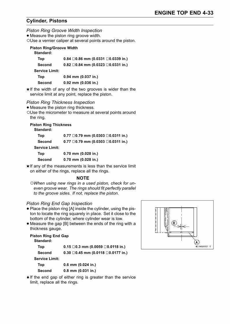
ENGINE TOP END 4-33Cylinder, Pistons
Piston Ring Groove Width Inspection•Measure the piston ring groove width.Use a vernier caliper at several points around the piston.Piston Ring/Groove WidthStandard:Top 0.84 ∼ 0.86 mm (0.0331 ∼ 0.0339 in.)Second 0.82 ∼ 0.84 mm (0.0323 ∼ 0.0331 in.)
Service Limit:Top 0.94 mm (0.037 in.)Second 0.92 mm (0.036 in.)
If the width of any of the two grooves is wider than theservice limit at any point, replace the piston.
Piston Ring Thickness Inspection•Measure the piston ring thickness.Use the micrometer to measure at several points aroundthe ring.
Piston Ring ThicknessStandard:Top 0.77 ∼ 0.79 mm (0.0303 ∼ 0.0311 in.)Second 0.77 ∼ 0.79 mm (0.0303 ∼ 0.0311 in.)
Service Limit:Top 0.70 mm (0.028 in.)Second 0.70 mm (0.028 in.)
If any of the measurements is less than the service limiton either of the rings, replace all the rings.
NOTEWhen using new rings in a used piston, check for un-even groove wear. The rings should fit perfectly parallelto the groove sides. If not, replace the piston.
Piston Ring End Gap Inspection•Place the piston ring [A] inside the cylinder, using the pis-ton to locate the ring squarely in place. Set it close to thebottom of the cylinder, where cylinder wear is low.•Measure the gap [B] between the ends of the ring with athickness gauge.
Piston Ring End GapStandard:Top 0.15 ∼ 0.3 mm (0.0059 ∼ 0.0118 in.)Second 0.30 ∼ 0.45 mm (0.0118 ∼ 0.0177 in.)
Service Limit:Top 0.6 mm (0.024 in.)Second 0.8 mm (0.031 in.)
If the end gap of either ring is greater than the servicelimit, replace all the rings.
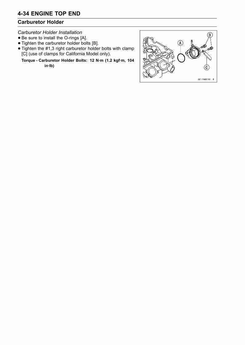
4-34 ENGINE TOP ENDCarburetor Holder
Carburetor Holder Installation•Be sure to install the O-rings [A].• Tighten the carburetor holder bolts [B].• Tighten the #1,3 right carburetor holder bolts with clamp[C] (use of clamps for California Model only).Torque - Carburetor Holder Bolts: 12 N·m (1.2 kgf·m, 104
in·lb)
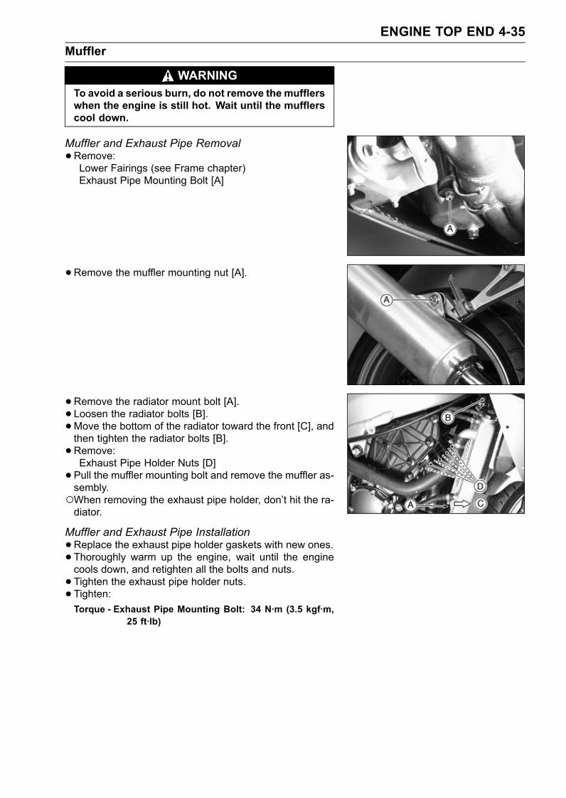
ENGINE TOP END 4-35Muffler
WARNINGTo avoid a serious burn, do not remove the mufflerswhen the engine is still hot. Wait until the mufflerscool down.
Muffler and Exhaust Pipe Removal•Remove:Lower Fairings (see Frame chapter)Exhaust Pipe Mounting Bolt [A]
•Remove the muffler mounting nut [A].
• Remove the radiator mount bolt [A].• Loosen the radiator bolts [B].•Move the bottom of the radiator toward the front [C], andthen tighten the radiator bolts [B].• Remove:Exhaust Pipe Holder Nuts [D]• Pull the muffler mounting bolt and remove the muffler as-sembly.When removing the exhaust pipe holder, don’t hit the ra-diator.
Muffler and Exhaust Pipe Installation•Replace the exhaust pipe holder gaskets with new ones.• Thoroughly warm up the engine, wait until the enginecools down, and retighten all the bolts and nuts.• Tighten the exhaust pipe holder nuts.• Tighten:Torque - Exhaust Pipe Mounting Bolt: 34 N·m (3.5 kgf·m,
25 ft·lb)
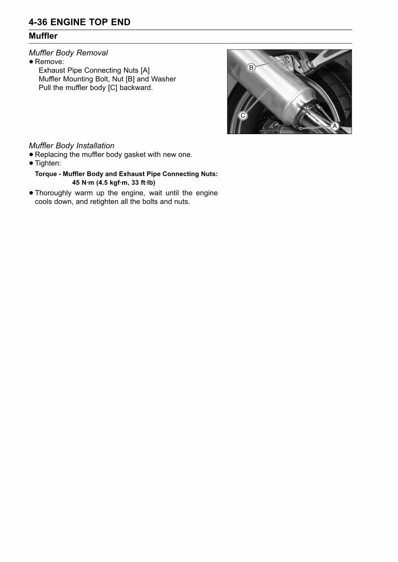
4-36 ENGINE TOP ENDMuffler
Muffler Body Removal•Remove:Exhaust Pipe Connecting Nuts [A]Muffler Mounting Bolt, Nut [B] and WasherPull the muffler body [C] backward.
Muffler Body Installation•Replacing the muffler body gasket with new one.• Tighten:Torque - Muffler Body and Exhaust Pipe Connecting Nuts:
45 N·m (4.5 kgf·m, 33 ft·lb)
•Thoroughly warm up the engine, wait until the enginecools down, and retighten all the bolts and nuts.
CLUTCH 5-1
5
ClutchTable of Contents
Exploded View........................................................................................................................ 5-2Specifications ......................................................................................................................... 5-3Clutch Lever and Cable .......................................................................................................... 5-4
Clutch Lever Free Play Inspection .................................................................................... 5-4Clutch Lever Free Play Adjustment .................................................................................. 5-4Clutch Cable Removal ...................................................................................................... 5-5Clutch Cable Installation ................................................................................................... 5-5Clutch Cable Lubrication................................................................................................... 5-5Clutch Lever Installation.................................................................................................... 5-5
Clutch Cover........................................................................................................................... 5-6Clutch Cover Removal ...................................................................................................... 5-6Clutch Cover Installation ................................................................................................... 5-6Clutch Release Shaft Removal ......................................................................................... 5-6Clutch Release Shaft Installation ...................................................................................... 5-6
Clutch ..................................................................................................................................... 5-7Clutch Removal................................................................................................................. 5-7Clutch Installation.............................................................................................................. 5-7Clutch Plate Assembly Inspection..................................................................................... 5-9Clutch Plate Assembly Adjustment ................................................................................... 5-10Clutch Plate Wear, Damage Inspection ............................................................................ 5-10Clutch Plate Warp Inspection............................................................................................ 5-10Clutch Spring Free Length Measurement ......................................................................... 5-11
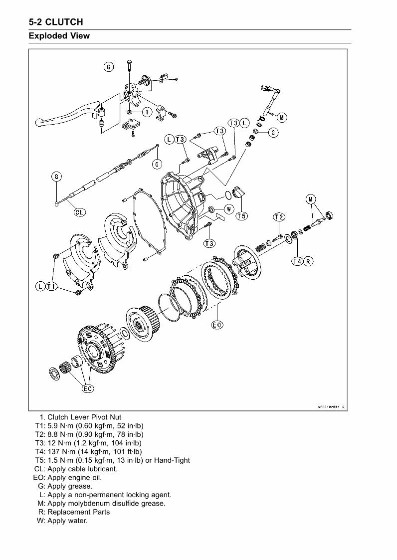
5-2 CLUTCHExploded View
1. Clutch Lever Pivot NutT1: 5.9 N·m (0.60 kgf·m, 52 in·lb)T2: 8.8 N·m (0.90 kgf·m, 78 in·lb)T3: 12 N·m (1.2 kgf·m, 104 in·lb)T4: 137 N·m (14 kgf·m, 101 ft·lb)T5: 1.5 N·m (0.15 kgf·m, 13 in·lb) or Hand-TightCL: Apply cable lubricant.EO: Apply engine oil.G: Apply grease.L: Apply a non-permanent locking agent.M: Apply molybdenum disulfide grease.R: Replacement PartsW: Apply water.
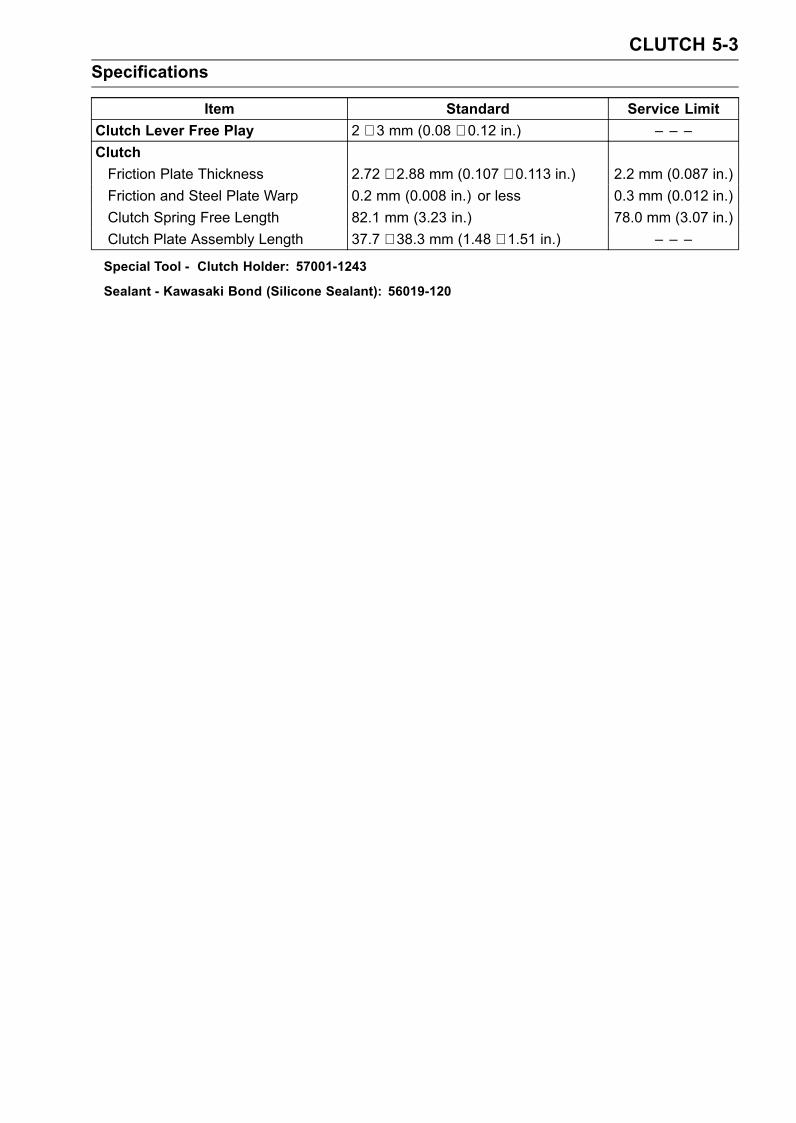
CLUTCH 5-3Specifications
Item Standard Service LimitClutch Lever Free Play 2 ∼ 3 mm (0.08 ∼ 0.12 in.) – – –ClutchFriction Plate Thickness 2.72 ∼ 2.88 mm (0.107 ∼ 0.113 in.) 2.2 mm (0.087 in.)Friction and Steel Plate Warp 0.2 mm (0.008 in.) or less 0.3 mm (0.012 in.)Clutch Spring Free Length 82.1 mm (3.23 in.) 78.0 mm (3.07 in.)Clutch Plate Assembly Length 37.7 ∼ 38.3 mm (1.48 ∼ 1.51 in.) – – –
Special Tool - Clutch Holder: 57001-1243
Sealant - Kawasaki Bond (Silicone Sealant): 56019-120
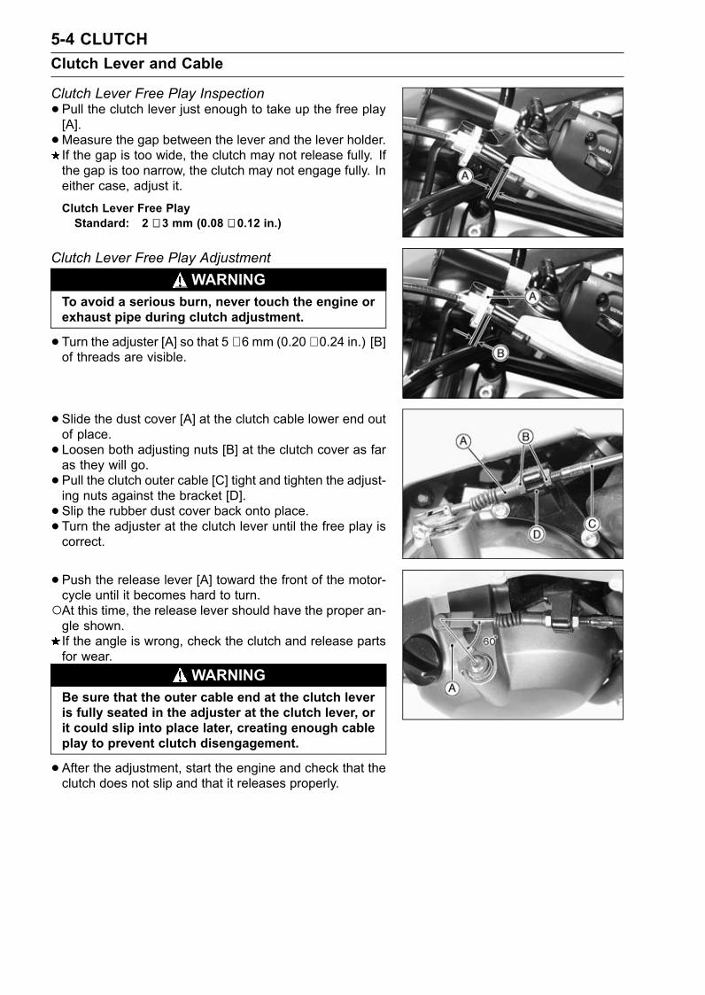
5-4 CLUTCHClutch Lever and Cable
Clutch Lever Free Play Inspection•Pull the clutch lever just enough to take up the free play[A].•Measure the gap between the lever and the lever holder.If the gap is too wide, the clutch may not release fully. Ifthe gap is too narrow, the clutch may not engage fully. Ineither case, adjust it.
Clutch Lever Free PlayStandard: 2 ∼ 3 mm (0.08 ∼ 0.12 in.)
Clutch Lever Free Play AdjustmentWARNING
To avoid a serious burn, never touch the engine orexhaust pipe during clutch adjustment.
•Turn the adjuster [A] so that 5 ∼ 6 mm (0.20 ∼ 0.24 in.) [B]of threads are visible.
• Slide the dust cover [A] at the clutch cable lower end outof place.• Loosen both adjusting nuts [B] at the clutch cover as faras they will go.• Pull the clutch outer cable [C] tight and tighten the adjust-ing nuts against the bracket [D].• Slip the rubber dust cover back onto place.• Turn the adjuster at the clutch lever until the free play iscorrect.
• Push the release lever [A] toward the front of the motor-cycle until it becomes hard to turn.At this time, the release lever should have the proper an-gle shown.If the angle is wrong, check the clutch and release partsfor wear.
WARNINGBe sure that the outer cable end at the clutch leveris fully seated in the adjuster at the clutch lever, orit could slip into place later, creating enough cableplay to prevent clutch disengagement.
•After the adjustment, start the engine and check that theclutch does not slip and that it releases properly.
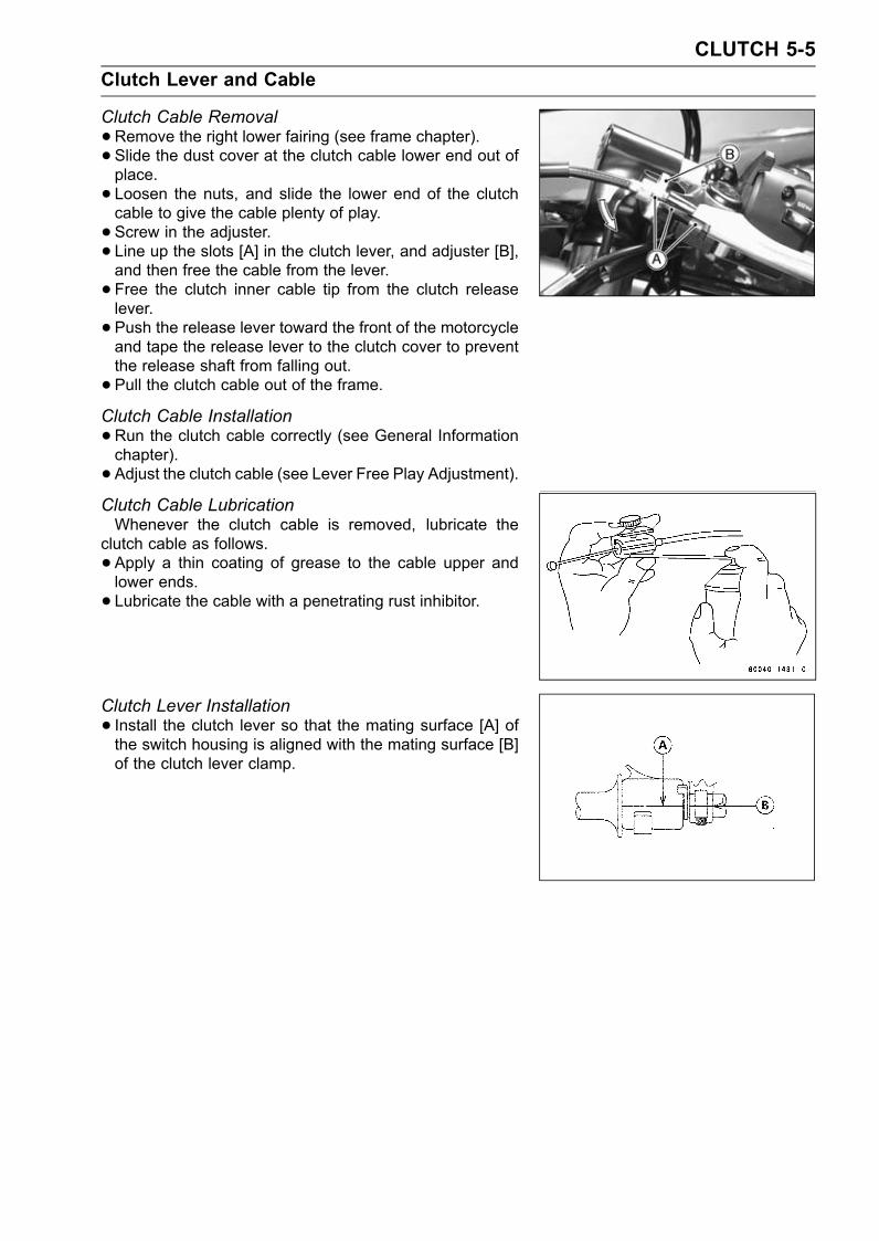
CLUTCH 5-5Clutch Lever and Cable
Clutch Cable Removal•Remove the right lower fairing (see frame chapter).• Slide the dust cover at the clutch cable lower end out ofplace.• Loosen the nuts, and slide the lower end of the clutchcable to give the cable plenty of play.• Screw in the adjuster.• Line up the slots [A] in the clutch lever, and adjuster [B],and then free the cable from the lever.• Free the clutch inner cable tip from the clutch releaselever.• Push the release lever toward the front of the motorcycleand tape the release lever to the clutch cover to preventthe release shaft from falling out.• Pull the clutch cable out of the frame.Clutch Cable Installation•Run the clutch cable correctly (see General Informationchapter).• Adjust the clutch cable (see Lever Free Play Adjustment).Clutch Cable LubricationWhenever the clutch cable is removed, lubricate the
clutch cable as follows.• Apply a thin coating of grease to the cable upper andlower ends.• Lubricate the cable with a penetrating rust inhibitor.
Clutch Lever Installation• Install the clutch lever so that the mating surface [A] ofthe switch housing is aligned with the mating surface [B]of the clutch lever clamp.
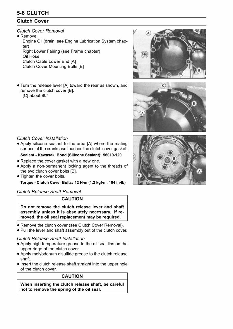
5-6 CLUTCHClutch Cover
Clutch Cover Removal•Remove:Engine Oil (drain, see Engine Lubrication System chap-ter)Right Lower Fairing (see Frame chapter)Oil HoseClutch Cable Lower End [A]Clutch Cover Mounting Bolts [B]
• Turn the release lever [A] toward the rear as shown, andremove the clutch cover [B].[C] about 90°
Clutch Cover Installation•Apply silicone sealant to the area [A] where the matingsurface of the crankcase touches the clutch cover gasket.Sealant - Kawasaki Bond (Silicone Sealant): 56019-120
•Replace the cover gasket with a new one.• Apply a non-permanent locking agent to the threads ofthe two clutch cover bolts [B].• Tighten the cover bolts.Torque - Clutch Cover Bolts: 12 N·m (1.2 kgf·m, 104 in·lb)
Clutch Release Shaft RemovalCAUTION
Do not remove the clutch release lever and shaftassembly unless it is absolutely necessary. If re-moved, the oil seal replacement may be required.
•Remove the clutch cover (see Clutch Cover Removal).• Pull the lever and shaft assembly out of the clutch cover.Clutch Release Shaft Installation•Apply high-temperature grease to the oil seal lips on theupper ridge of the clutch cover.• Apply molybdenum disulfide grease to the clutch releaseshaft.• Insert the clutch release shaft straight into the upper holeof the clutch cover.
CAUTIONWhen inserting the clutch release shaft, be carefulnot to remove the spring of the oil seal.
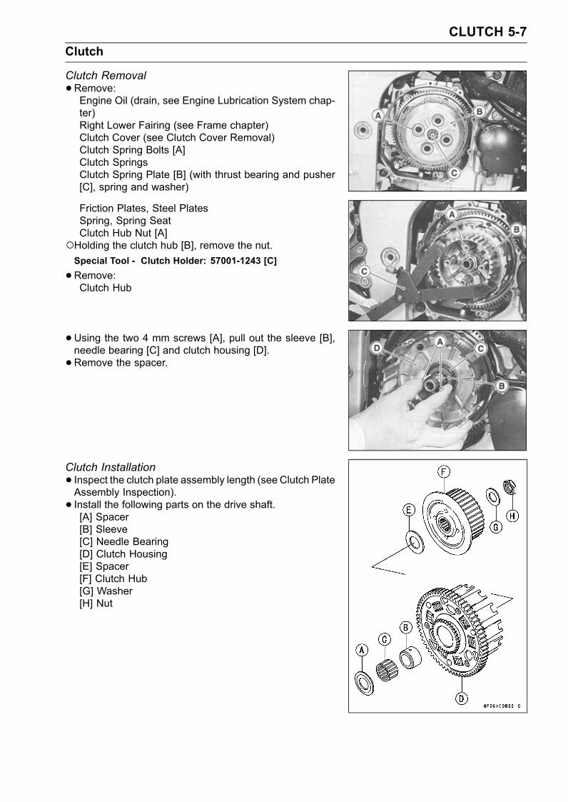
CLUTCH 5-7Clutch
Clutch Removal•Remove:Engine Oil (drain, see Engine Lubrication System chap-ter)Right Lower Fairing (see Frame chapter)Clutch Cover (see Clutch Cover Removal)Clutch Spring Bolts [A]Clutch SpringsClutch Spring Plate [B] (with thrust bearing and pusher[C], spring and washer)
Friction Plates, Steel PlatesSpring, Spring SeatClutch Hub Nut [A]
Holding the clutch hub [B], remove the nut.Special Tool - Clutch Holder: 57001-1243 [C]
•Remove:Clutch Hub
•Using the two 4 mm screws [A], pull out the sleeve [B],needle bearing [C] and clutch housing [D].• Remove the spacer.
Clutch Installation• Inspect the clutch plate assembly length (see Clutch PlateAssembly Inspection).• Install the following parts on the drive shaft.[A] Spacer[B] Sleeve[C] Needle Bearing[D] Clutch Housing[E] Spacer[F] Clutch Hub[G] Washer[H] Nut
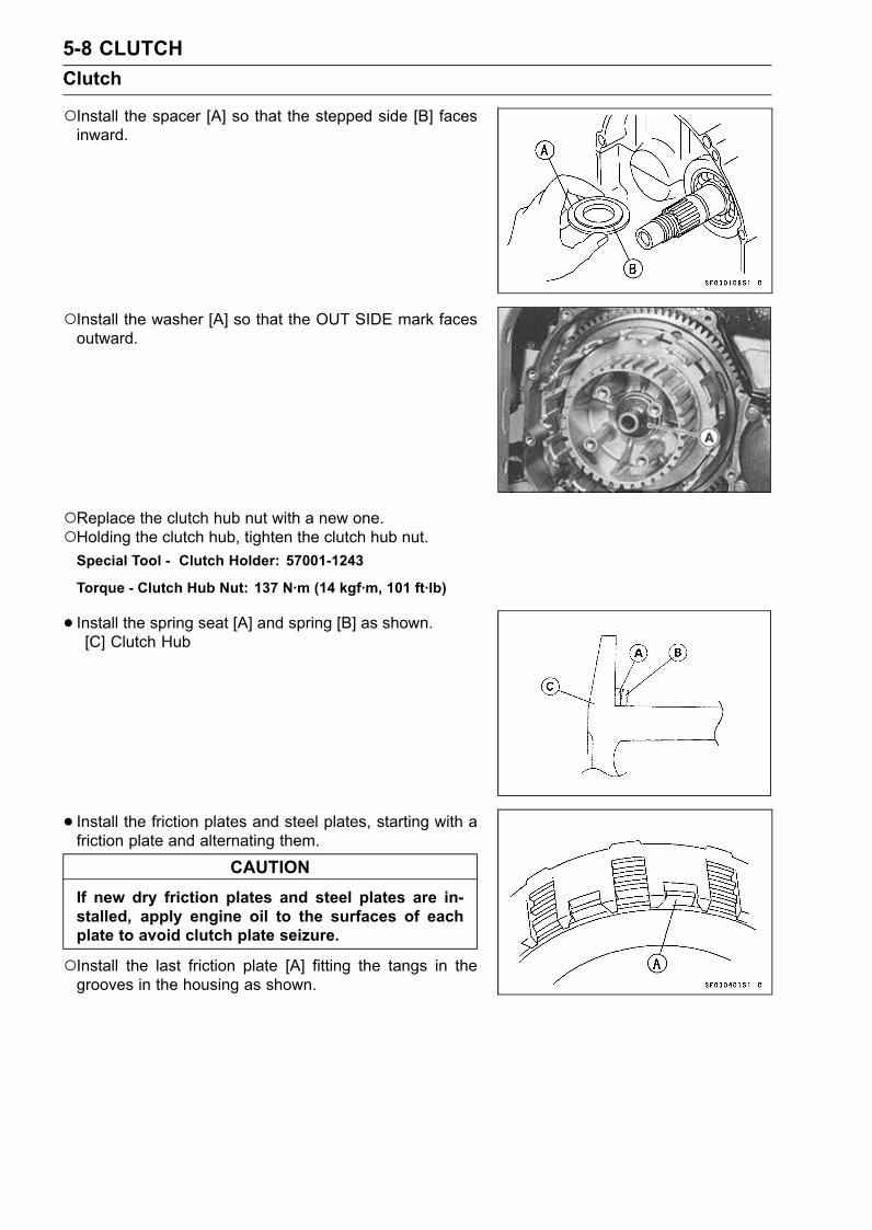
5-8 CLUTCHClutch
Install the spacer [A] so that the stepped side [B] facesinward.
Install the washer [A] so that the OUT SIDE mark facesoutward.
Replace the clutch hub nut with a new one.Holding the clutch hub, tighten the clutch hub nut.Special Tool - Clutch Holder: 57001-1243
Torque - Clutch Hub Nut: 137 N·m (14 kgf·m, 101 ft·lb)
• Install the spring seat [A] and spring [B] as shown.[C] Clutch Hub
• Install the friction plates and steel plates, starting with afriction plate and alternating them.
CAUTIONIf new dry friction plates and steel plates are in-stalled, apply engine oil to the surfaces of eachplate to avoid clutch plate seizure.
Install the last friction plate [A] fitting the tangs in thegrooves in the housing as shown.
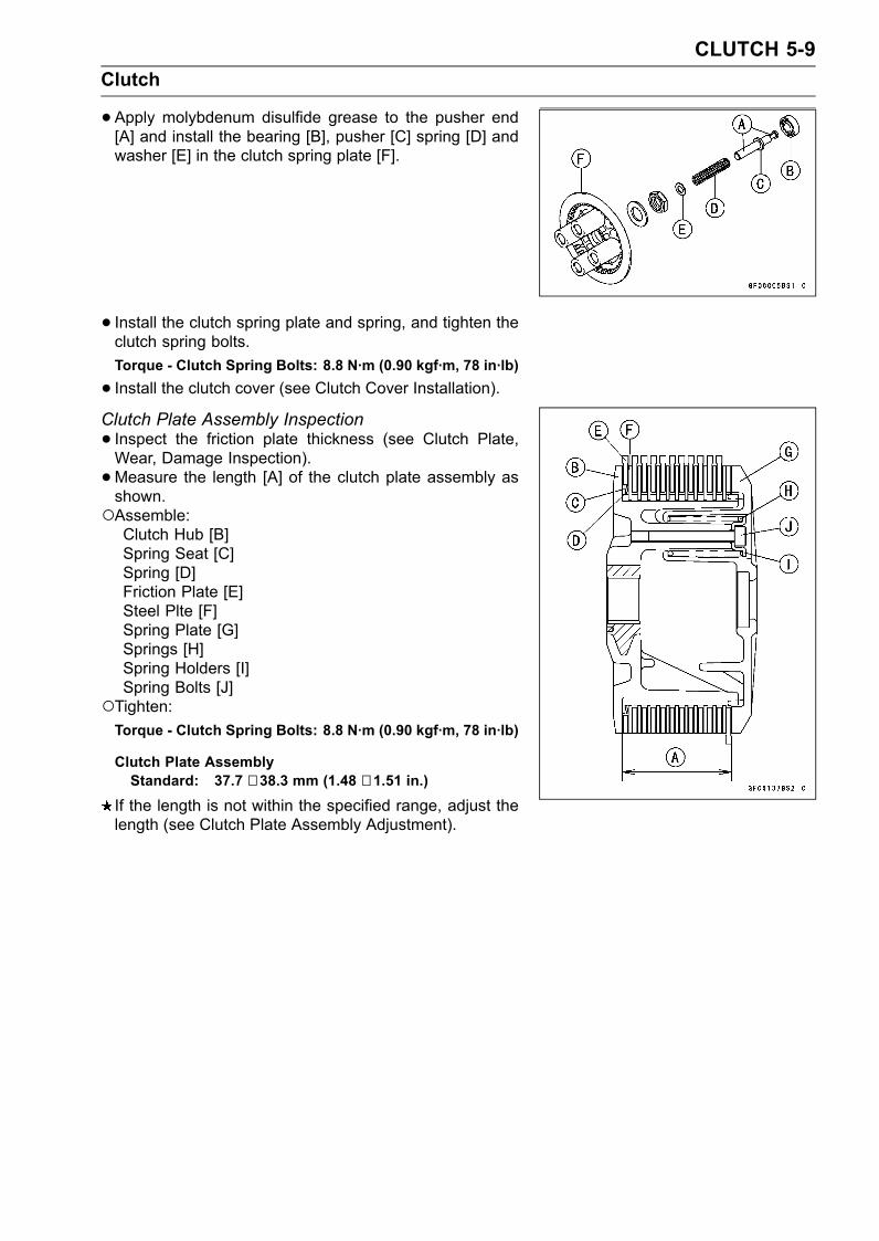
CLUTCH 5-9Clutch
•Apply molybdenum disulfide grease to the pusher end[A] and install the bearing [B], pusher [C] spring [D] andwasher [E] in the clutch spring plate [F].
• Install the clutch spring plate and spring, and tighten theclutch spring bolts.Torque - Clutch Spring Bolts: 8.8 N·m (0.90 kgf·m, 78 in·lb)
• Install the clutch cover (see Clutch Cover Installation).Clutch Plate Assembly Inspection• Inspect the friction plate thickness (see Clutch Plate,Wear, Damage Inspection).•Measure the length [A] of the clutch plate assembly asshown.Assemble:Clutch Hub [B]Spring Seat [C]Spring [D]Friction Plate [E]Steel Plte [F]Spring Plate [G]Springs [H]Spring Holders [I]Spring Bolts [J]
Tighten:Torque - Clutch Spring Bolts: 8.8 N·m (0.90 kgf·m, 78 in·lb)
Clutch Plate AssemblyStandard: 37.7 ∼ 38.3 mm (1.48 ∼ 1.51 in.)
If the length is not within the specified range, adjust thelength (see Clutch Plate Assembly Adjustment).
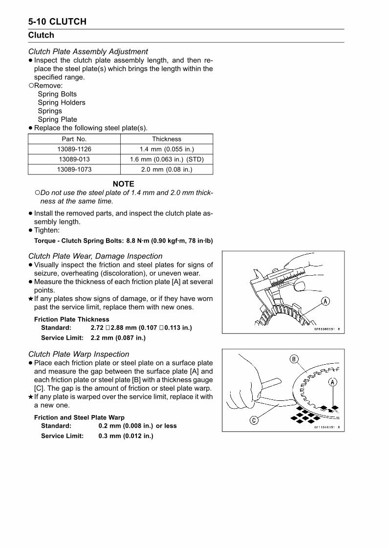
5-10 CLUTCHClutch
Clutch Plate Assembly Adjustment• Inspect the clutch plate assembly length, and then re-place the steel plate(s) which brings the length within thespecified range.Remove:Spring BoltsSpring HoldersSpringsSpring Plate•Replace the following steel plate(s).
Part No. Thickness13089-1126 1.4 mm (0.055 in.)13089-013 1.6 mm (0.063 in.) (STD)13089-1073 2.0 mm (0.08 in.)
NOTEDo not use the steel plate of 1.4 mm and 2.0 mm thick-ness at the same time.
• Install the removed parts, and inspect the clutch plate as-sembly length.• Tighten:Torque - Clutch Spring Bolts: 8.8 N·m (0.90 kgf·m, 78 in·lb)
Clutch Plate Wear, Damage Inspection•Visually inspect the friction and steel plates for signs ofseizure, overheating (discoloration), or uneven wear.•Measure the thickness of each friction plate [A] at severalpoints.If any plates show signs of damage, or if they have wornpast the service limit, replace them with new ones.
Friction Plate ThicknessStandard: 2.72 ∼ 2.88 mm (0.107 ∼ 0.113 in.)Service Limit: 2.2 mm (0.087 in.)
Clutch Plate Warp Inspection•Place each friction plate or steel plate on a surface plateand measure the gap between the surface plate [A] andeach friction plate or steel plate [B] with a thickness gauge[C]. The gap is the amount of friction or steel plate warp.If any plate is warped over the service limit, replace it witha new one.
Friction and Steel Plate WarpStandard: 0.2 mm (0.008 in.) or lessService Limit: 0.3 mm (0.012 in.)
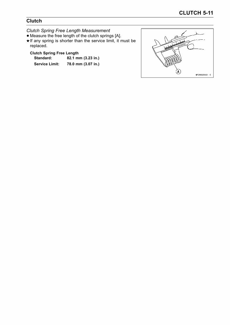
CLUTCH 5-11Clutch
Clutch Spring Free Length Measurement•Measure the free length of the clutch springs [A].If any spring is shorter than the service limit, it must bereplaced.
Clutch Spring Free LengthStandard: 82.1 mm (3.23 in.)Service Limit: 78.0 mm (3.07 in.)

ENGINE LUBRICATION SYSTEM 6-1
6
Engine Lubrication System
Table of ContentsExploded View........................................................................................................................ 6-2Engine Oil Flow Chart............................................................................................................. 6-3Specifications ......................................................................................................................... 6-4Engine Oil and Oil Filter.......................................................................................................... 6-5
Oil Level Inspection........................................................................................................... 6-5Engine Oil Change............................................................................................................ 6-5Oil Filter Change............................................................................................................... 6-6
Oil Pan.................................................................................................................................... 6-7Oil Pan Removal ............................................................................................................... 6-7Oil Pan Installation ............................................................................................................ 6-7
Oil Pressure Relief Valve........................................................................................................ 6-8Oil Pressure Relief Valve Removal ................................................................................... 6-8Oil Pressure Relief Valve Installation ................................................................................ 6-8Oil Pressure Relief Valve Inspection................................................................................. 6-8
Oil Pump................................................................................................................................. 6-9Oil Pump Removal ............................................................................................................ 6-9Oil Pump Installation ......................................................................................................... 6-9Oil Pump Drive Gear Removal.......................................................................................... 6-10Oil Pump Drive Gear Installation....................................................................................... 6-10
Oil Cooler................................................................................................................................ 6-11Oil Cooler Removal........................................................................................................... 6-11Oil Cooler Installation........................................................................................................ 6-11
Oil Pressure Measurement..................................................................................................... 6-12Oil Pressure Measurement ............................................................................................... 6-12
Oil Pressure Switch ................................................................................................................ 6-13Oil Pressure Switch Removal ........................................................................................... 6-13Oil Pressure Switch Installation ........................................................................................ 6-13
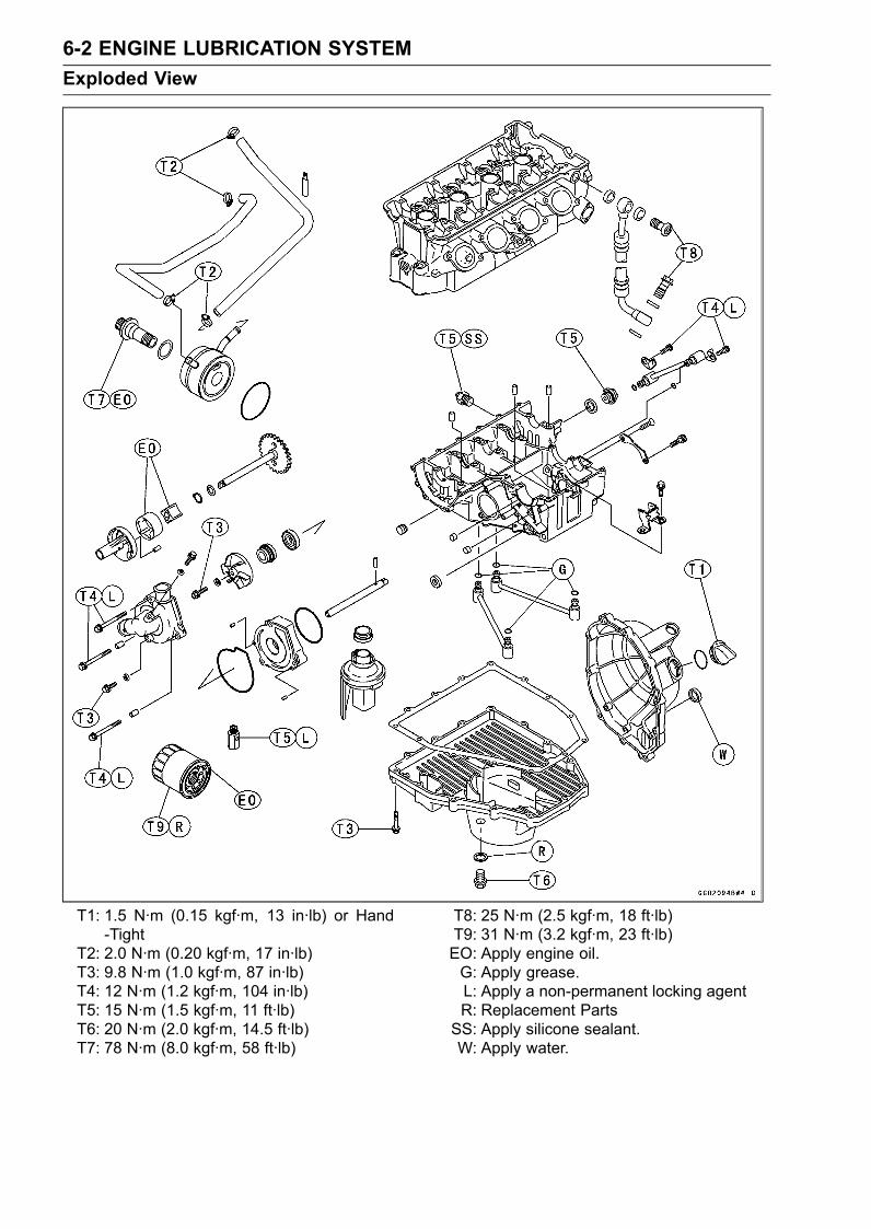
6-2 ENGINE LUBRICATION SYSTEMExploded View
T1: 1.5 N·m (0.15 kgf·m, 13 in·lb) or Hand-Tight
T2: 2.0 N·m (0.20 kgf·m, 17 in·lb)T3: 9.8 N·m (1.0 kgf·m, 87 in·lb)T4: 12 N·m (1.2 kgf·m, 104 in·lb)T5: 15 N·m (1.5 kgf·m, 11 ft·lb)T6: 20 N·m (2.0 kgf·m, 14.5 ft·lb)T7: 78 N·m (8.0 kgf·m, 58 ft·lb)
T8: 25 N·m (2.5 kgf·m, 18 ft·lb)T9: 31 N·m (3.2 kgf·m, 23 ft·lb)EO: Apply engine oil.G: Apply grease.L: Apply a non-permanent locking agentR: Replacement PartsSS: Apply silicone sealant.W: Apply water.
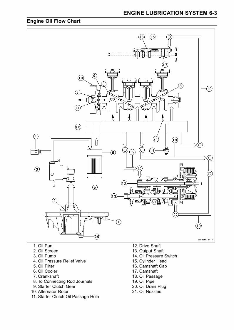
ENGINE LUBRICATION SYSTEM 6-3Engine Oil Flow Chart
1. Oil Pan2. Oil Screen3. Oil Pump4. Oil Pressure Relief Valve5. Oil Filter6. Oil Cooler7. Crankshaft8. To Connecting Rod Journals9. Starter Clutch Gear10. Alternator Rotor11. Starter Clutch Oil Passage Hole
12. Drive Shaft13. Output Shaft14. Oil Pressure Switch15. Cylinder Head16. Camshaft Cap17. Camshaft18. Oil Passage19. Oil Pipe20. Oil Drain Plug21. Oil Nozzles
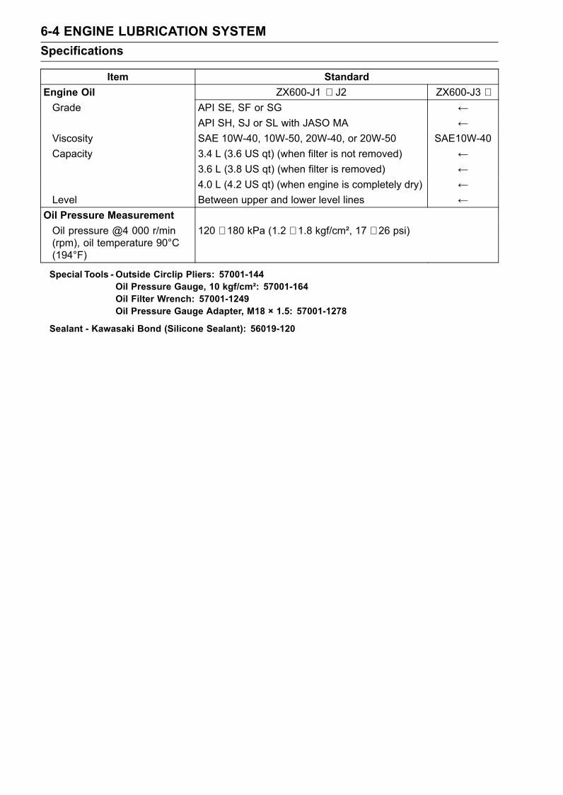
6-4 ENGINE LUBRICATION SYSTEMSpecifications
Item StandardEngine Oil ZX600-J1 ∼ J2 ZX600-J3 ∼Grade API SE, SF or SG ←
API SH, SJ or SL with JASO MA ←Viscosity SAE 10W-40, 10W-50, 20W-40, or 20W-50 SAE10W-40Capacity 3.4 L (3.6 US qt) (when filter is not removed) ←
3.6 L (3.8 US qt) (when filter is removed) ←4.0 L (4.2 US qt) (when engine is completely dry) ←
Level Between upper and lower level lines ←Oil Pressure MeasurementOil pressure @4 000 r/min(rpm), oil temperature 90°C(194°F)
120 ∼ 180 kPa (1.2 ∼ 1.8 kgf/cm², 17 ∼ 26 psi)
Special Tools - Outside Circlip Pliers: 57001-144Oil Pressure Gauge, 10 kgf/cm²: 57001-164Oil Filter Wrench: 57001-1249Oil Pressure Gauge Adapter, M18 × 1.5: 57001-1278
Sealant - Kawasaki Bond (Silicone Sealant): 56019-120
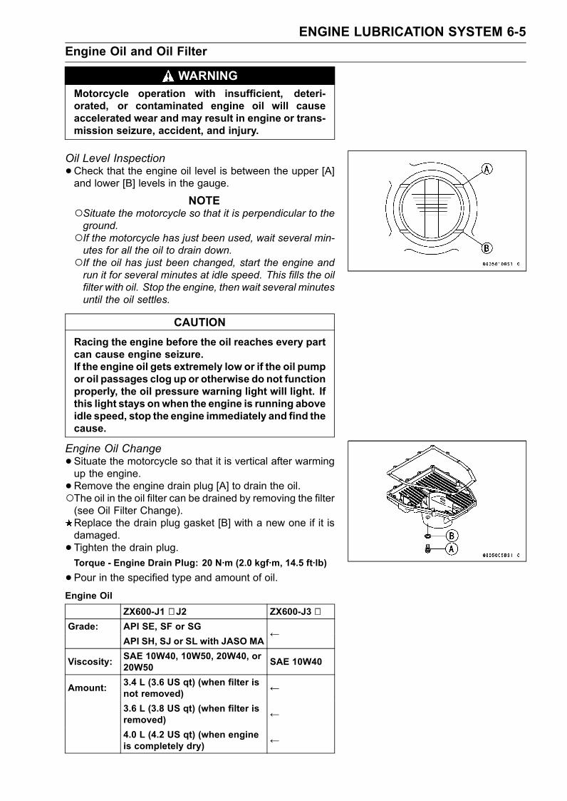
ENGINE LUBRICATION SYSTEM 6-5Engine Oil and Oil Filter
WARNINGMotorcycle operation with insufficient, deteri-orated, or contaminated engine oil will causeaccelerated wear and may result in engine or trans-mission seizure, accident, and injury.
Oil Level Inspection•Check that the engine oil level is between the upper [A]and lower [B] levels in the gauge.
NOTESituate the motorcycle so that it is perpendicular to theground.If the motorcycle has just been used, wait several min-utes for all the oil to drain down.If the oil has just been changed, start the engine andrun it for several minutes at idle speed. This fills the oilfilter with oil. Stop the engine, then wait several minutesuntil the oil settles.
CAUTIONRacing the engine before the oil reaches every partcan cause engine seizure.If the engine oil gets extremely low or if the oil pumpor oil passages clog up or otherwise do not functionproperly, the oil pressure warning light will light. Ifthis light stays onwhen the engine is running aboveidle speed, stop the engine immediately and find thecause.
Engine Oil Change•Situate the motorcycle so that it is vertical after warmingup the engine.•Remove the engine drain plug [A] to drain the oil.The oil in the oil filter can be drained by removing the filter(see Oil Filter Change).Replace the drain plug gasket [B] with a new one if it isdamaged.• Tighten the drain plug.Torque - Engine Drain Plug: 20 N·m (2.0 kgf·m, 14.5 ft·lb)
•Pour in the specified type and amount of oil.Engine Oil
ZX600-J1 ∼ J2 ZX600-J3 ∼Grade: API SE, SF or SG
API SH, SJ or SL with JASO MA←
Viscosity: SAE 10W40, 10W50, 20W40, or20W50 SAE 10W40
Amount: 3.4 L (3.6 US qt) (when filter isnot removed) ←
3.6 L (3.8 US qt) (when filter isremoved) ←
4.0 L (4.2 US qt) (when engineis completely dry) ←
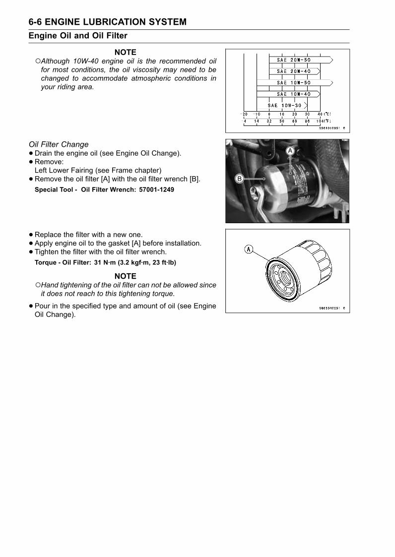
6-6 ENGINE LUBRICATION SYSTEMEngine Oil and Oil Filter
NOTEAlthough 10W-40 engine oil is the recommended oilfor most conditions, the oil viscosity may need to bechanged to accommodate atmospheric conditions inyour riding area.
Oil Filter Change•Drain the engine oil (see Engine Oil Change).•Remove:Left Lower Fairing (see Frame chapter)•Remove the oil filter [A] with the oil filter wrench [B].Special Tool - Oil Filter Wrench: 57001-1249
•Replace the filter with a new one.• Apply engine oil to the gasket [A] before installation.• Tighten the filter with the oil filter wrench.Torque - Oil Filter: 31 N·m (3.2 kgf·m, 23 ft·lb)
NOTEHand tightening of the oil filter can not be allowed sinceit does not reach to this tightening torque.
•Pour in the specified type and amount of oil (see EngineOil Change).
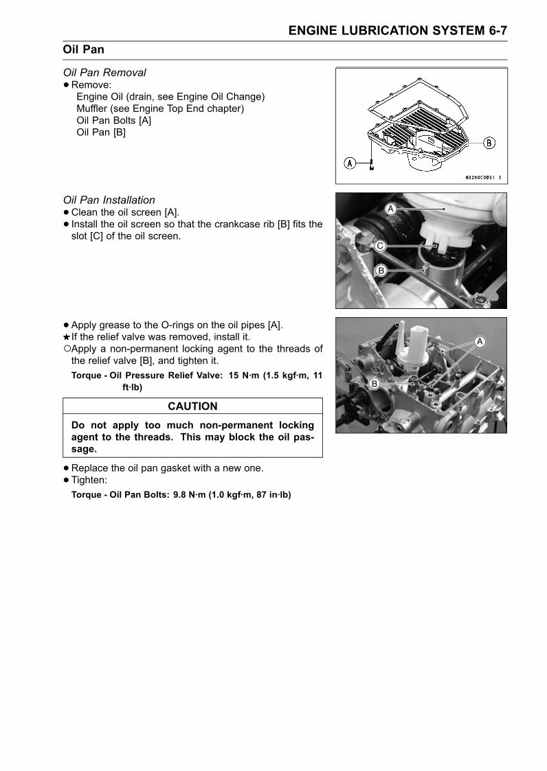
ENGINE LUBRICATION SYSTEM 6-7Oil Pan
Oil Pan Removal•Remove:Engine Oil (drain, see Engine Oil Change)Muffler (see Engine Top End chapter)Oil Pan Bolts [A]Oil Pan [B]
Oil Pan Installation•Clean the oil screen [A].• Install the oil screen so that the crankcase rib [B] fits theslot [C] of the oil screen.
• Apply grease to the O-rings on the oil pipes [A].If the relief valve was removed, install it.Apply a non-permanent locking agent to the threads ofthe relief valve [B], and tighten it.Torque - Oil Pressure Relief Valve: 15 N·m (1.5 kgf·m, 11
ft·lb)
CAUTIONDo not apply too much non-permanent lockingagent to the threads. This may block the oil pas-sage.
•Replace the oil pan gasket with a new one.• Tighten:Torque - Oil Pan Bolts: 9.8 N·m (1.0 kgf·m, 87 in·lb)
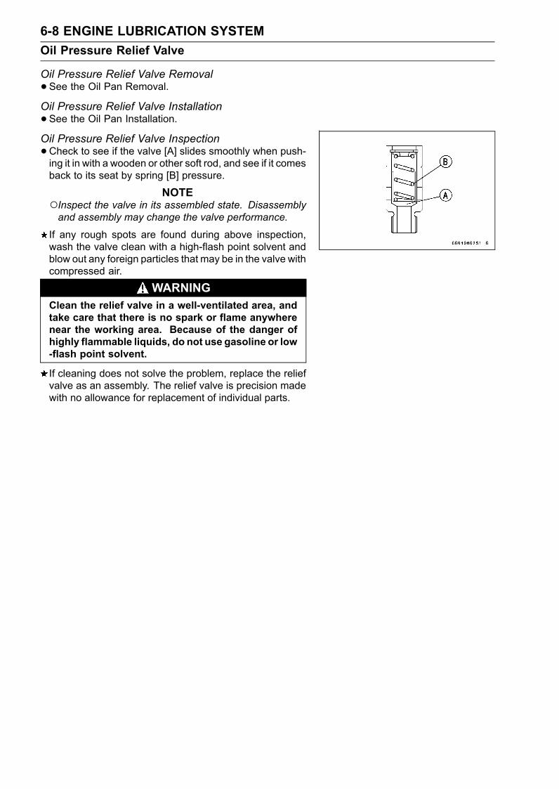
6-8 ENGINE LUBRICATION SYSTEMOil Pressure Relief Valve
Oil Pressure Relief Valve Removal•See the Oil Pan Removal.Oil Pressure Relief Valve Installation•See the Oil Pan Installation.Oil Pressure Relief Valve Inspection•Check to see if the valve [A] slides smoothly when push-ing it in with a wooden or other soft rod, and see if it comesback to its seat by spring [B] pressure.
NOTEInspect the valve in its assembled state. Disassemblyand assembly may change the valve performance.
If any rough spots are found during above inspection,wash the valve clean with a high-flash point solvent andblow out any foreign particles that may be in the valve withcompressed air.
WARNINGClean the relief valve in a well-ventilated area, andtake care that there is no spark or flame anywherenear the working area. Because of the danger ofhighly flammable liquids, do not use gasoline or low-flash point solvent.
If cleaning does not solve the problem, replace the reliefvalve as an assembly. The relief valve is precision madewith no allowance for replacement of individual parts.
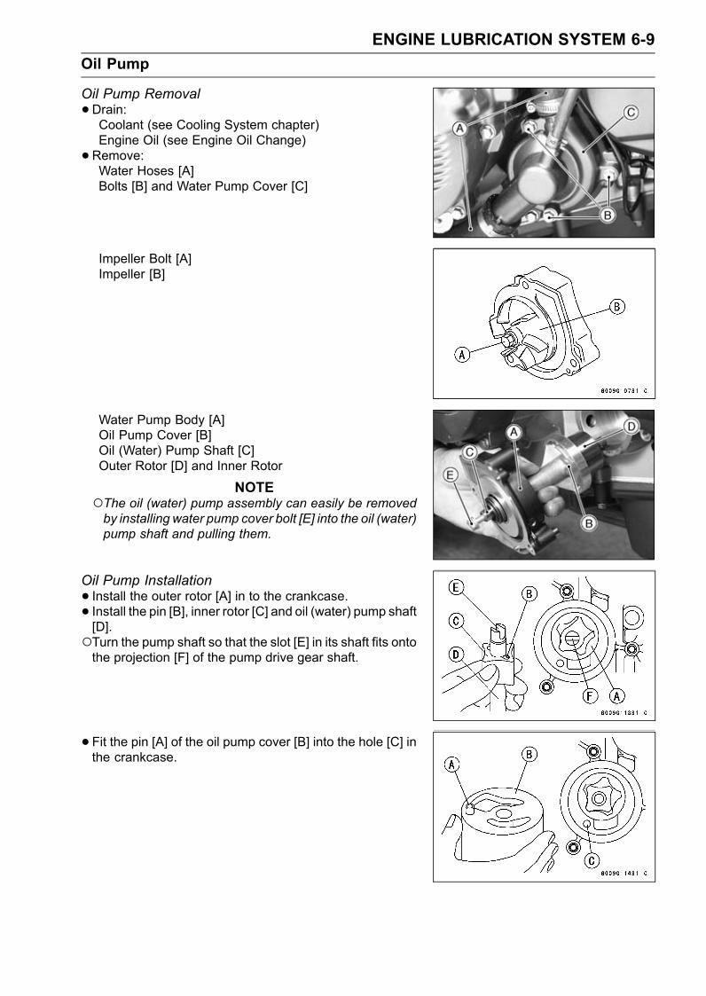
ENGINE LUBRICATION SYSTEM 6-9Oil Pump
Oil Pump Removal•Drain:Coolant (see Cooling System chapter)Engine Oil (see Engine Oil Change)•Remove:Water Hoses [A]Bolts [B] and Water Pump Cover [C]
Impeller Bolt [A]Impeller [B]
Water Pump Body [A]Oil Pump Cover [B]Oil (Water) Pump Shaft [C]Outer Rotor [D] and Inner Rotor
NOTEThe oil (water) pump assembly can easily be removedby installing water pump cover bolt [E] into the oil (water)pump shaft and pulling them.
Oil Pump Installation• Install the outer rotor [A] in to the crankcase.• Install the pin [B], inner rotor [C] and oil (water) pump shaft[D].Turn the pump shaft so that the slot [E] in its shaft fits ontothe projection [F] of the pump drive gear shaft.
• Fit the pin [A] of the oil pump cover [B] into the hole [C] inthe crankcase.
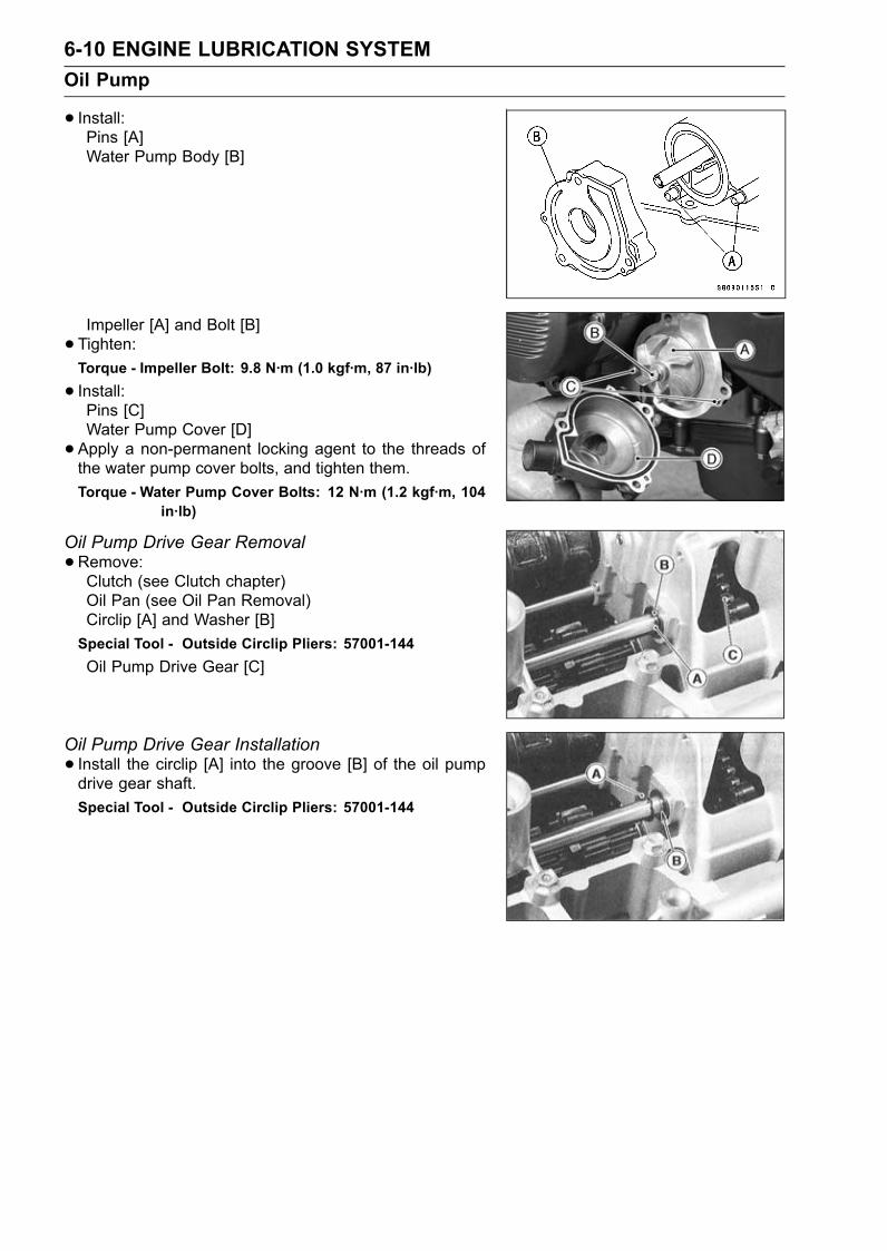
6-10 ENGINE LUBRICATION SYSTEMOil Pump
• Install:Pins [A]Water Pump Body [B]
Impeller [A] and Bolt [B]• Tighten:Torque - Impeller Bolt: 9.8 N·m (1.0 kgf·m, 87 in·lb)
• Install:Pins [C]Water Pump Cover [D]• Apply a non-permanent locking agent to the threads ofthe water pump cover bolts, and tighten them.Torque - Water Pump Cover Bolts: 12 N·m (1.2 kgf·m, 104
in·lb)
Oil Pump Drive Gear Removal•Remove:Clutch (see Clutch chapter)Oil Pan (see Oil Pan Removal)Circlip [A] and Washer [B]Special Tool - Outside Circlip Pliers: 57001-144Oil Pump Drive Gear [C]
Oil Pump Drive Gear Installation• Install the circlip [A] into the groove [B] of the oil pumpdrive gear shaft.Special Tool - Outside Circlip Pliers: 57001-144
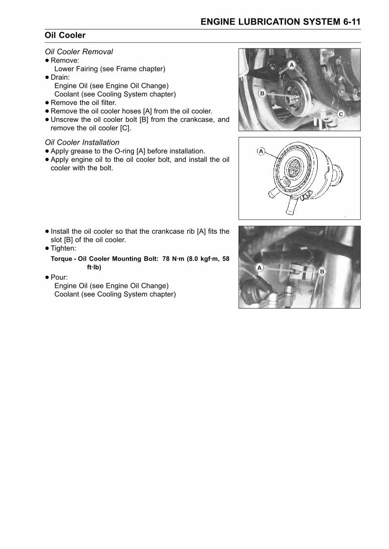
ENGINE LUBRICATION SYSTEM 6-11Oil Cooler
Oil Cooler Removal•Remove:Lower Fairing (see Frame chapter)•Drain:Engine Oil (see Engine Oil Change)Coolant (see Cooling System chapter)•Remove the oil filter.• Remove the oil cooler hoses [A] from the oil cooler.• Unscrew the oil cooler bolt [B] from the crankcase, andremove the oil cooler [C].
Oil Cooler Installation•Apply grease to the O-ring [A] before installation.• Apply engine oil to the oil cooler bolt, and install the oilcooler with the bolt.
• Install the oil cooler so that the crankcase rib [A] fits theslot [B] of the oil cooler.• Tighten:Torque - Oil Cooler Mounting Bolt: 78 N·m (8.0 kgf·m, 58
ft·lb)
•Pour:Engine Oil (see Engine Oil Change)Coolant (see Cooling System chapter)
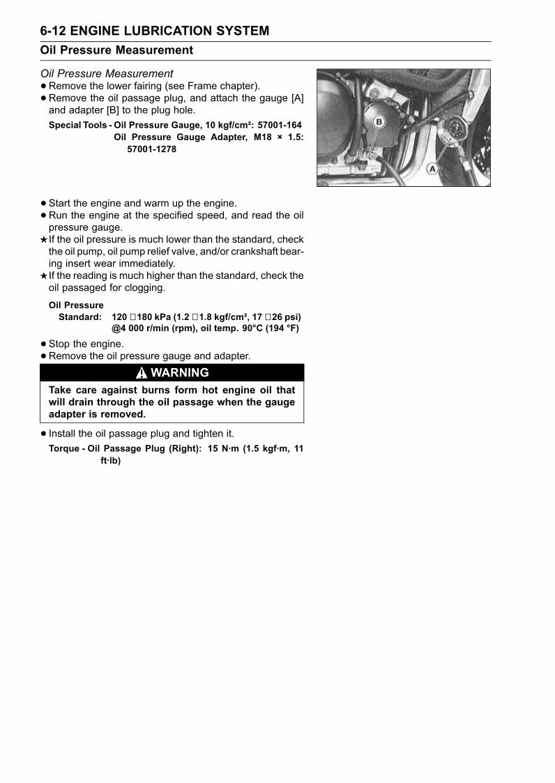
6-12 ENGINE LUBRICATION SYSTEMOil Pressure Measurement
Oil Pressure Measurement•Remove the lower fairing (see Frame chapter).• Remove the oil passage plug, and attach the gauge [A]and adapter [B] to the plug hole.Special Tools - Oil Pressure Gauge, 10 kgf/cm²: 57001-164
Oil Pressure Gauge Adapter, M18 × 1.5:57001-1278
•Start the engine and warm up the engine.•Run the engine at the specified speed, and read the oilpressure gauge.If the oil pressure is much lower than the standard, checkthe oil pump, oil pump relief valve, and/or crankshaft bear-ing insert wear immediately.If the reading is much higher than the standard, check theoil passaged for clogging.
Oil PressureStandard: 120 ∼ 180 kPa (1.2 ∼ 1.8 kgf/cm², 17 ∼ 26 psi)
@4 000 r/min (rpm), oil temp. 90°C (194 °F)
•Stop the engine.•Remove the oil pressure gauge and adapter.WARNING
Take care against burns form hot engine oil thatwill drain through the oil passage when the gaugeadapter is removed.
• Install the oil passage plug and tighten it.Torque - Oil Passage Plug (Right): 15 N·m (1.5 kgf·m, 11
ft·lb)
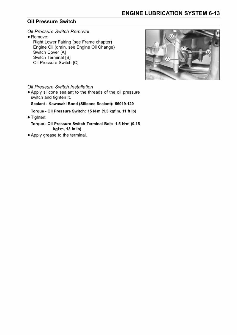
ENGINE LUBRICATION SYSTEM 6-13Oil Pressure Switch
Oil Pressure Switch Removal•Remove:Right Lower Fairing (see Frame chapter)Engine Oil (drain, see Engine Oil Change)Switch Cover [A]Switch Terminal [B]Oil Pressure Switch [C]
Oil Pressure Switch Installation•Apply silicone sealant to the threads of the oil pressureswitch and tighten it.Sealant - Kawasaki Bond (Silicone Sealant): 56019-120
Torque - Oil Pressure Switch: 15 N·m (1.5 kgf·m, 11 ft·lb)
•Tighten:Torque - Oil Pressure Switch Terminal Bolt: 1.5 N·m (0.15
kgf·m, 13 in·lb)
•Apply grease to the terminal.

ENGINE REMOVAL/INSTALLATION 7-1
7
Engine Removal/Installation
Table of ContentsExploded View........................................................................................................................ 7-2Specifications ......................................................................................................................... 7-3Engine Removal/Installation ................................................................................................... 7-4
Engine Removal................................................................................................................ 7-4Engine Installation............................................................................................................. 7-5
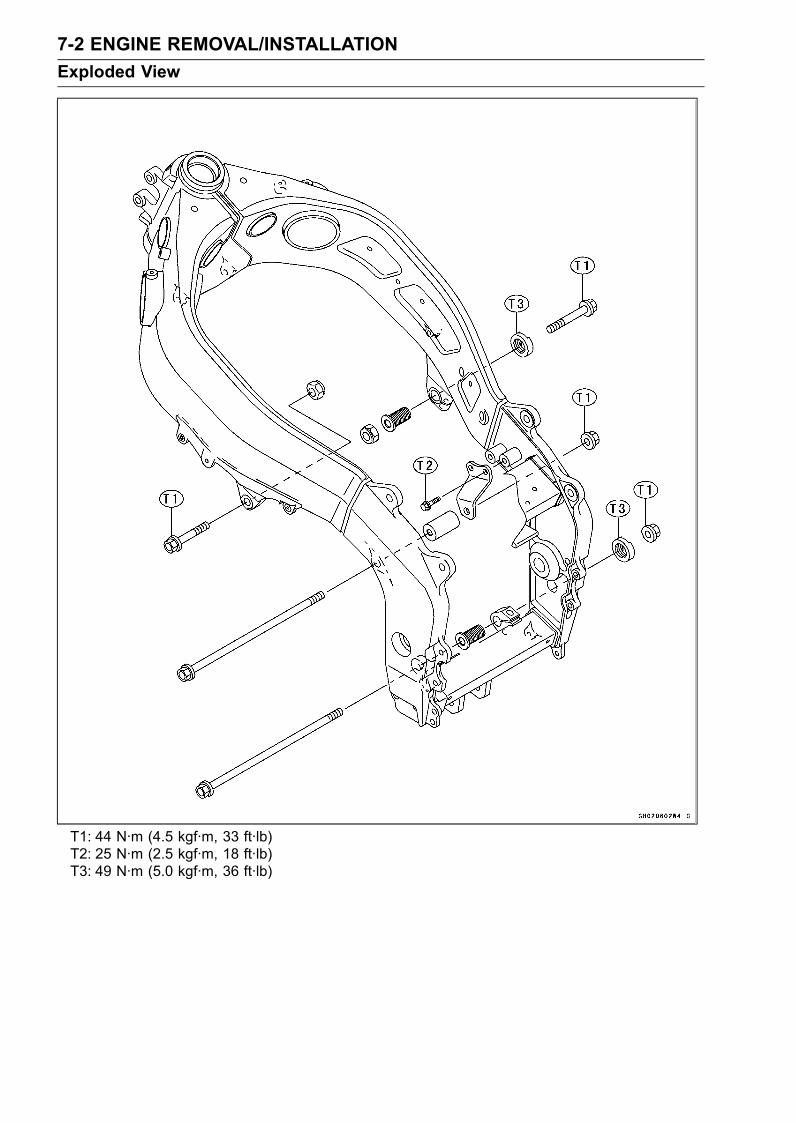
7-2 ENGINE REMOVAL/INSTALLATIONExploded View
T1: 44 N·m (4.5 kgf·m, 33 ft·lb)T2: 25 N·m (2.5 kgf·m, 18 ft·lb)T3: 49 N·m (5.0 kgf·m, 36 ft·lb)
ENGINE REMOVAL/INSTALLATION 7-3Specifications
Special Tool - Jack: 57001-1238Engine Mount Nut Wrench: 57001-1450
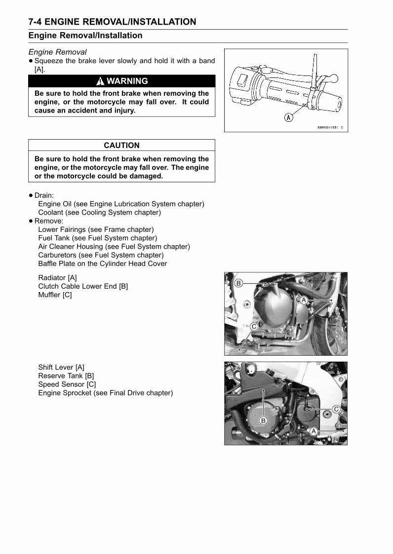
7-4 ENGINE REMOVAL/INSTALLATIONEngine Removal/Installation
Engine Removal•Squeeze the brake lever slowly and hold it with a band[A].
WARNINGBe sure to hold the front brake when removing theengine, or the motorcycle may fall over. It couldcause an accident and injury.
CAUTIONBe sure to hold the front brake when removing theengine, or the motorcycle may fall over. The engineor the motorcycle could be damaged.
•Drain:Engine Oil (see Engine Lubrication System chapter)Coolant (see Cooling System chapter)•Remove:Lower Fairings (see Frame chapter)Fuel Tank (see Fuel System chapter)Air Cleaner Housing (see Fuel System chapter)Carburetors (see Fuel System chapter)Baffle Plate on the Cylinder Head Cover
Radiator [A]Clutch Cable Lower End [B]Muffler [C]
Shift Lever [A]Reserve Tank [B]Speed Sensor [C]Engine Sprocket (see Final Drive chapter)
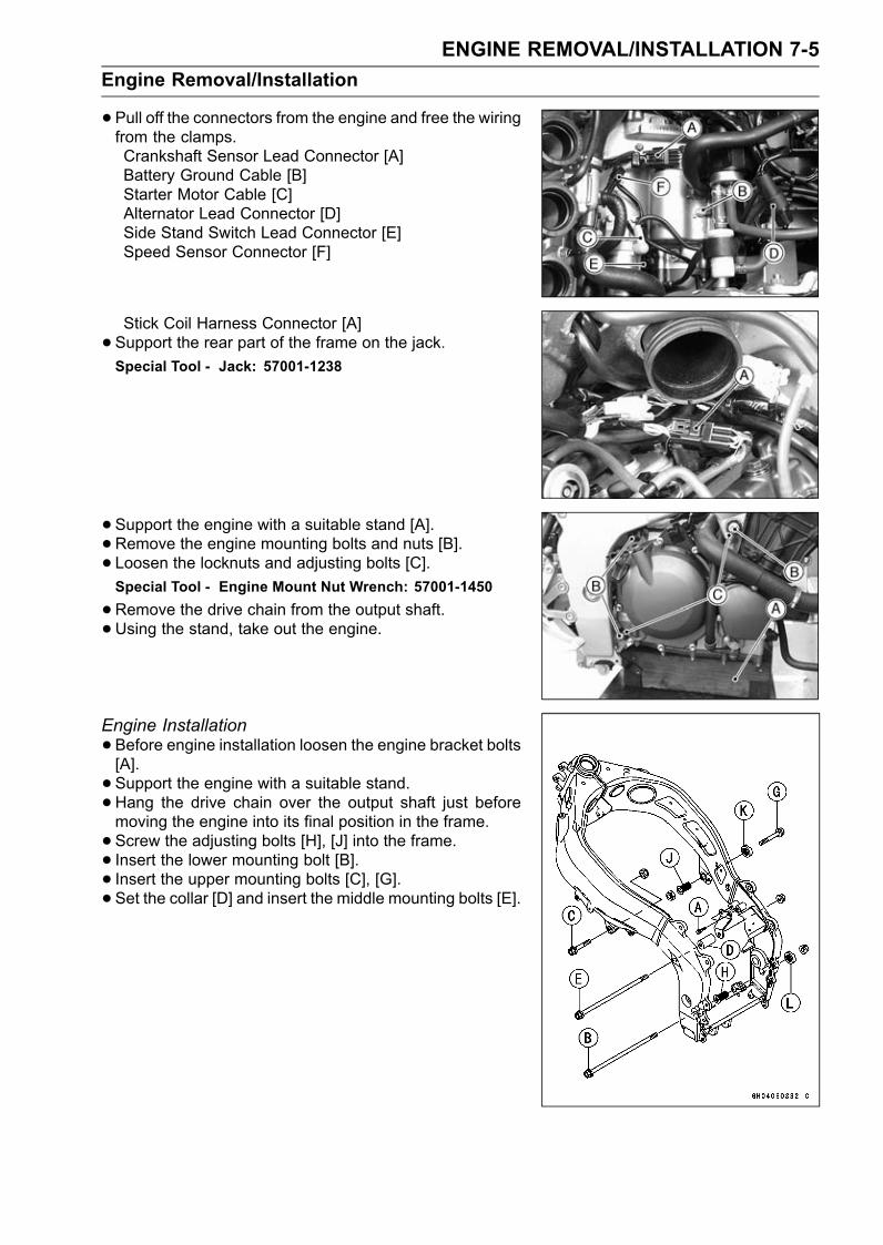
ENGINE REMOVAL/INSTALLATION 7-5Engine Removal/Installation
•Pull off the connectors from the engine and free the wiringfrom the clamps.Crankshaft Sensor Lead Connector [A]Battery Ground Cable [B]Starter Motor Cable [C]Alternator Lead Connector [D]Side Stand Switch Lead Connector [E]Speed Sensor Connector [F]
Stick Coil Harness Connector [A]• Support the rear part of the frame on the jack.Special Tool - Jack: 57001-1238
•Support the engine with a suitable stand [A].• Remove the engine mounting bolts and nuts [B].• Loosen the locknuts and adjusting bolts [C].Special Tool - Engine Mount Nut Wrench: 57001-1450
•Remove the drive chain from the output shaft.• Using the stand, take out the engine.
Engine Installation•Before engine installation loosen the engine bracket bolts[A].• Support the engine with a suitable stand.•Hang the drive chain over the output shaft just beforemoving the engine into its final position in the frame.• Screw the adjusting bolts [H], [J] into the frame.• Insert the lower mounting bolt [B].• Insert the upper mounting bolts [C], [G].• Set the collar [D] and insert the middle mounting bolts [E].
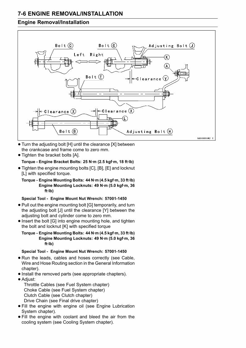
7-6 ENGINE REMOVAL/INSTALLATIONEngine Removal/Installation
•Turn the adjusting bolt [H] until the clearance [X] betweenthe crankcase and frame come to zero mm.• Tighten the bracket bolts [A].Torque - Engine Bracket Bolts: 25 N·m (2.5 kgf·m, 18 ft·lb)
•Tighten the engine mounting bolts [C], [B], [E] and locknut[L] with specified torque.Torque - EngineMounting Bolts: 44 N·m (4.5 kgf·m, 33 ft·lb)
Engine Mounting Locknuts: 49 N·m (5.0 kgf·m, 36ft·lb)
Special Tool - Engine Mount Nut Wrench: 57001-1450
•Pull out the engine mounting bolt [G] temporarily, and turnthe adjusting bolt [J] until the clearance [Y] between theadjusting bolt and cylinder come to zero mm.• Insert the bolt [G] into engine mounting hole, and tightenthe bolt and locknut [K] with specified torqueTorque - EngineMounting Bolts: 44 N·m (4.5 kgf·m, 33 ft·lb)
Engine Mounting Locknuts: 49 N·m (5.0 kgf·m, 36ft·lb)
Special Tool - Engine Mount Nut Wrench: 57001-1450
•Run the leads, cables and hoses correctly (see Cable,Wire and Hose Routing section in the General Informationchapter).• Install the removed parts (see appropriate chapters).• Adjust:Throttle Cables (see Fuel System chapter)Choke Cable (see Fuel System chapter)Clutch Cable (see Clutch chapter)Drive Chain (see Final drive chapter)• Fill the engine with engine oil (see Engine LubricationSystem chapter).• Fill the engine with coolant and bleed the air from thecooling system (see Cooling System chapter).
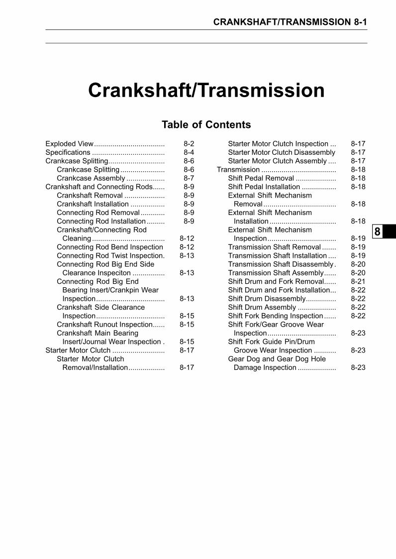
CRANKSHAFT/TRANSMISSION 8-1
8
Crankshaft/TransmissionTable of Contents
Exploded View................................... 8-2Specifications .................................... 8-4Crankcase Splitting............................ 8-6
Crankcase Splitting ...................... 8-6Crankcase Assembly ................... 8-7
Crankshaft and Connecting Rods...... 8-9Crankshaft Removal .................... 8-9Crankshaft Installation ................. 8-9Connecting Rod Removal ............ 8-9Connecting Rod Installation ......... 8-9Crankshaft/Connecting RodCleaning .................................... 8-12
Connecting Rod Bend Inspection 8-12Connecting Rod Twist Inspection. 8-13Connecting Rod Big End SideClearance Inspeciton ................ 8-13
Connecting Rod Big EndBearing Insert/Crankpin WearInspection.................................. 8-13
Crankshaft Side ClearanceInspection.................................. 8-15
Crankshaft Runout Inspection...... 8-15Crankshaft Main BearingInsert/Journal Wear Inspection . 8-15
Starter Motor Clutch .......................... 8-17Starter Motor ClutchRemoval/Installation.................. 8-17
Starter Motor Clutch Inspection ... 8-17Starter Motor Clutch Disassembly 8-17Starter Motor Clutch Assembly .... 8-17
Transmission ..................................... 8-18Shift Pedal Removal .................... 8-18Shift Pedal Installation ................. 8-18External Shift MechanismRemoval .................................... 8-18
External Shift MechanismInstallation ................................. 8-18
External Shift MechanismInspection.................................. 8-19
Transmission Shaft Removal ....... 8-19Transmission Shaft Installation .... 8-19Transmission Shaft Disassembly. 8-20Transmission Shaft Assembly...... 8-20Shift Drum and Fork Removal...... 8-21Shift Drum and Fork Installation... 8-22Shift Drum Disassembly............... 8-22Shift Drum Assembly ................... 8-22Shift Fork Bending Inspection ...... 8-22Shift Fork/Gear Groove WearInspection.................................. 8-23
Shift Fork Guide Pin/DrumGroove Wear Inspection ........... 8-23
Gear Dog and Gear Dog HoleDamage Inspection ................... 8-23
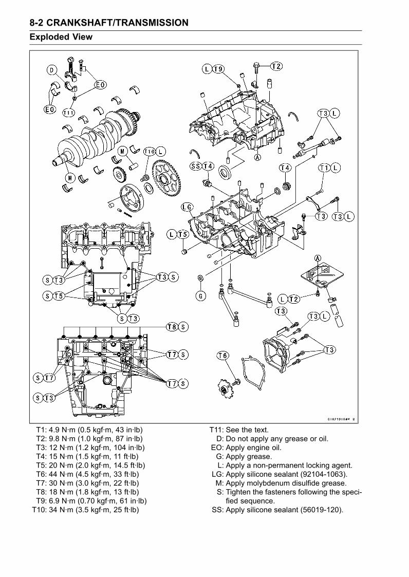
8-2 CRANKSHAFT/TRANSMISSIONExploded View
T1: 4.9 N·m (0.5 kgf·m, 43 in·lb)T2: 9.8 N·m (1.0 kgf·m, 87 in·lb)T3: 12 N·m (1.2 kgf·m, 104 in·lb)T4: 15 N·m (1.5 kgf·m, 11 ft·lb)T5: 20 N·m (2.0 kgf·m, 14.5 ft·lb)T6: 44 N·m (4.5 kgf·m, 33 ft·lb)T7: 30 N·m (3.0 kgf·m, 22 ft·lb)T8: 18 N·m (1.8 kgf·m, 13 ft·lb)T9: 6.9 N·m (0.70 kgf·m, 61 in·lb)T10: 34 N·m (3.5 kgf·m, 25 ft·lb)
T11: See the text.D: Do not apply any grease or oil.EO: Apply engine oil.G: Apply grease.L: Apply a non-permanent locking agent.
LG: Apply silicone sealant (92104-1063).M: Apply molybdenum disulfide grease.S: Tighten the fasteners following the speci-fied sequence.
SS: Apply silicone sealant (56019-120).
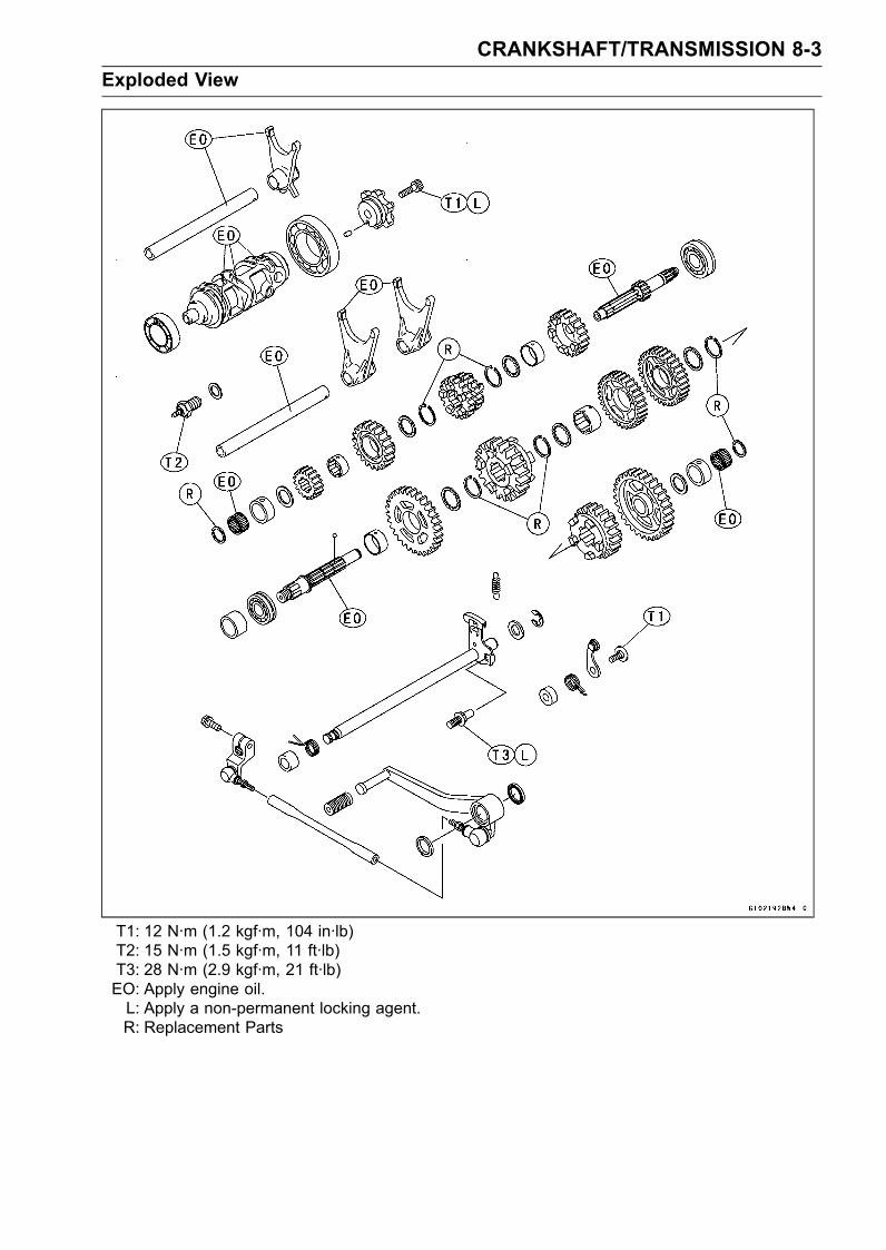
CRANKSHAFT/TRANSMISSION 8-3Exploded View
T1: 12 N·m (1.2 kgf·m, 104 in·lb)T2: 15 N·m (1.5 kgf·m, 11 ft·lb)T3: 28 N·m (2.9 kgf·m, 21 ft·lb)EO: Apply engine oil.L: Apply a non-permanent locking agent.R: Replacement Parts
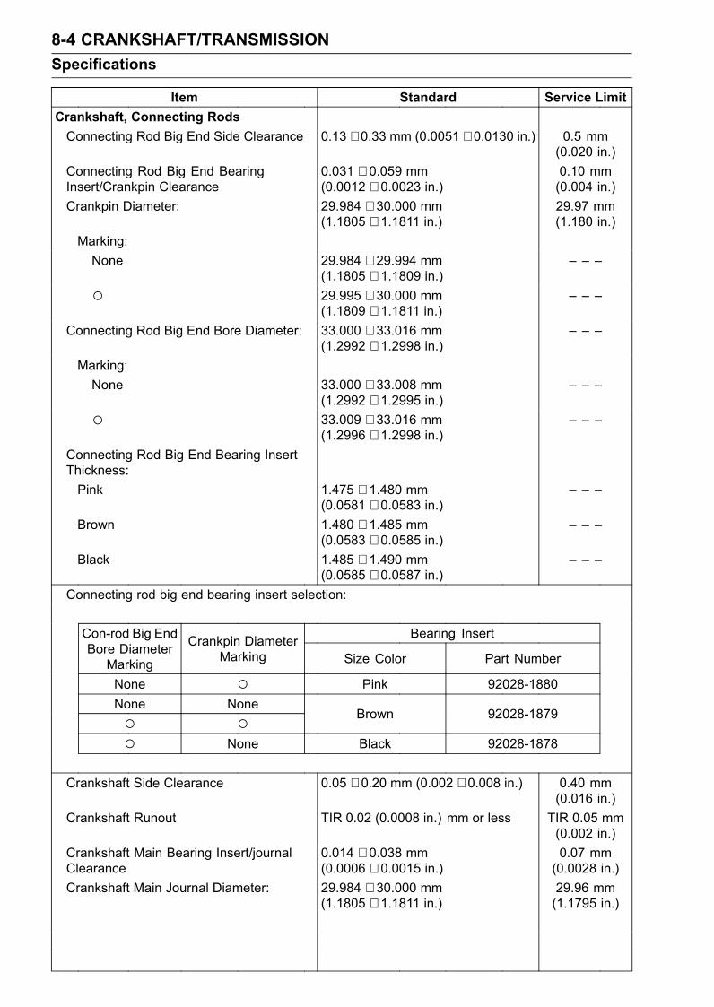
8-4 CRANKSHAFT/TRANSMISSIONSpecifications
Item Standard Service LimitCrankshaft, Connecting RodsConnecting Rod Big End Side Clearance 0.13 ∼ 0.33 mm (0.0051 ∼ 0.0130 in.) 0.5 mm
(0.020 in.)Connecting Rod Big End BearingInsert/Crankpin Clearance
0.031 ∼ 0.059 mm(0.0012 ∼ 0.0023 in.)
0.10 mm(0.004 in.)
Crankpin Diameter: 29.984 ∼ 30.000 mm(1.1805 ∼ 1.1811 in.)
29.97 mm(1.180 in.)
Marking:None 29.984 ∼ 29.994 mm
(1.1805 ∼ 1.1809 in.)– – –
29.995 ∼ 30.000 mm(1.1809 ∼ 1.1811 in.)
– – –
Connecting Rod Big End Bore Diameter: 33.000 ∼ 33.016 mm(1.2992 ∼ 1.2998 in.)
– – –
Marking:None 33.000 ∼ 33.008 mm
(1.2992 ∼ 1.2995 in.)– – –
33.009 ∼ 33.016 mm(1.2996 ∼ 1.2998 in.)
– – –
Connecting Rod Big End Bearing InsertThickness:Pink 1.475 ∼ 1.480 mm
(0.0581 ∼ 0.0583 in.)– – –
Brown 1.480 ∼ 1.485 mm(0.0583 ∼ 0.0585 in.)
– – –
Black 1.485 ∼ 1.490 mm(0.0585 ∼ 0.0587 in.)
– – –
Connecting rod big end bearing insert selection:
Bearing InsertCon-rod Big EndBore DiameterMarking
Crankpin DiameterMarking Size Color Part Number
None Pink 92028-1880None None Brown 92028-1879
None Black 92028-1878
Crankshaft Side Clearance 0.05 ∼ 0.20 mm (0.002 ∼ 0.008 in.) 0.40 mm(0.016 in.)
Crankshaft Runout TIR 0.02 (0.0008 in.) mm or less TIR 0.05 mm(0.002 in.)
Crankshaft Main Bearing Insert/journalClearance
0.014 ∼ 0.038 mm(0.0006 ∼ 0.0015 in.)
0.07 mm(0.0028 in.)
Crankshaft Main Journal Diameter: 29.984 ∼ 30.000 mm(1.1805 ∼ 1.1811 in.)
29.96 mm(1.1795 in.)
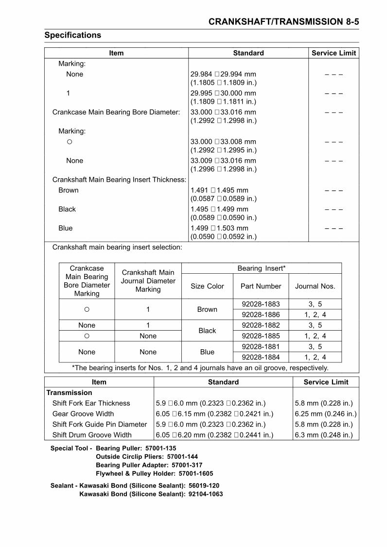
CRANKSHAFT/TRANSMISSION 8-5Specifications
Item Standard Service LimitMarking:None 29.984 ∼ 29.994 mm
(1.1805 ∼ 1.1809 in.)– – –
1 29.995 ∼ 30.000 mm(1.1809 ∼ 1.1811 in.)
– – –
Crankcase Main Bearing Bore Diameter: 33.000 ∼ 33.016 mm(1.2992 ∼ 1.2998 in.)
– – –
Marking: 33.000 ∼ 33.008 mm
(1.2992 ∼ 1.2995 in.)– – –
None 33.009 ∼ 33.016 mm(1.2996 ∼ 1.2998 in.)
– – –
Crankshaft Main Bearing Insert Thickness:Brown 1.491 ∼ 1.495 mm
(0.0587 ∼ 0.0589 in.)– – –
Black 1.495 ∼ 1.499 mm(0.0589 ∼ 0.0590 in.)
– – –
Blue 1.499 ∼ 1.503 mm(0.0590 ∼ 0.0592 in.)
– – –
Crankshaft main bearing insert selection:
Bearing Insert*CrankcaseMain BearingBore DiameterMarking
Crankshaft MainJournal Diameter
Marking Size Color Part Number Journal Nos.
92028-1883 3, 5 1 Brown92028-1886 1, 2, 4
None 1 92028-1882 3, 5 None
Black92028-1885 1, 2, 492028-1881 3, 5
None None Blue92028-1884 1, 2, 4
*The bearing inserts for Nos. 1, 2 and 4 journals have an oil groove, respectively.
Item Standard Service LimitTransmissionShift Fork Ear Thickness 5.9 ∼ 6.0 mm (0.2323 ∼ 0.2362 in.) 5.8 mm (0.228 in.)Gear Groove Width 6.05 ∼ 6.15 mm (0.2382 ∼ 0.2421 in.) 6.25 mm (0.246 in.)Shift Fork Guide Pin Diameter 5.9 ∼ 6.0 mm (0.2323 ∼ 0.2362 in.) 5.8 mm (0.228 in.)Shift Drum Groove Width 6.05 ∼ 6.20 mm (0.2382 ∼ 0.2441 in.) 6.3 mm (0.248 in.)
Special Tool - Bearing Puller: 57001-135Outside Circlip Pliers: 57001-144Bearing Puller Adapter: 57001-317Flywheel & Pulley Holder: 57001-1605
Sealant - Kawasaki Bond (Silicone Sealant): 56019-120Kawasaki Bond (Silicone Sealant): 92104-1063
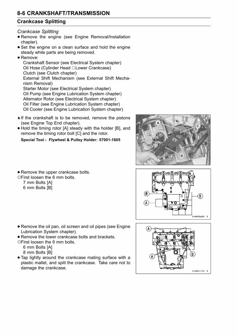
8-6 CRANKSHAFT/TRANSMISSIONCrankcase Splitting
Crankcase Splitting•Remove the engine (see Engine Removal/Installationchapter).• Set the engine on a clean surface and hold the enginesteady while parts are being removed.•Remove:Crankshaft Sensor (see Electrical System chapter)Oil Hose (Cylinder Head ∼ Lower Crankcase)Clutch (see Clutch chapter)External Shift Mechanism (see External Shift Mecha-nism Removal)Starter Motor (see Electrical System chapter)Oil Pump (see Engine Lubrication System chapter)Alternator Rotor (see Electrical System chapter)Oil Filter (see Engine Lubrication System chapter)Oil Cooler (see Engine Lubrication System chapter)
If the crankshaft is to be removed, remove the pistons(see Engine Top End chapter).• Hold the timing rotor [A] steady with the holder [B], andremove the timing rotor bolt [C] and the rotor.Special Tool - Flywheel & Pulley Holder: 57001-1605
•Remove the upper crankcase bolts.First loosen the 6 mm bolts.7 mm Bolts [A]6 mm Bolts [B]
•Remove the oil pan, oil screen and oil pipes (see EngineLubrication System chapter).• Remove the lower crankcase bolts and brackets.First loosen the 6 mm bolts.6 mm Bolts [A]8 mm Bolts [B]• Tap lightly around the crankcase mating surface with aplastic mallet, and split the crankcase. Take care not todamage the crankcase.
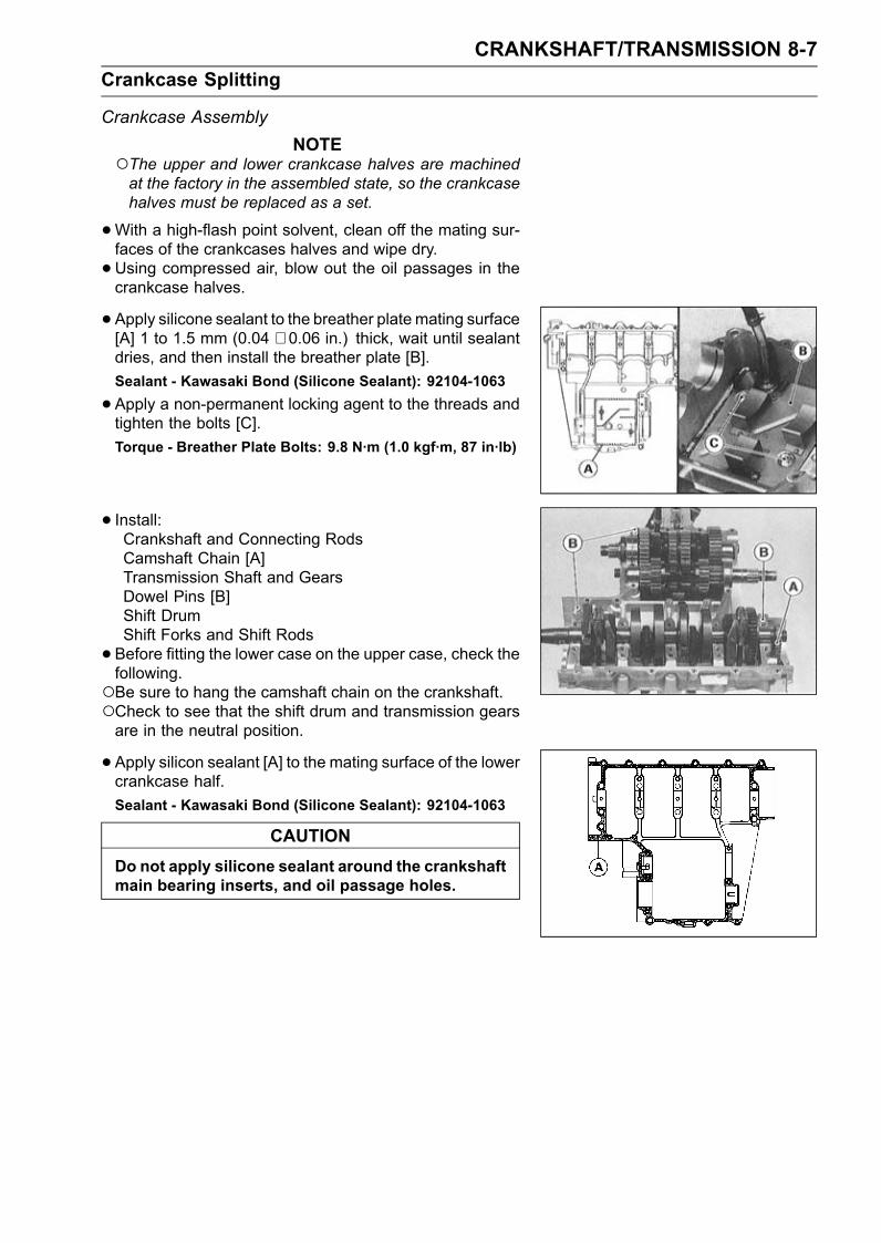
CRANKSHAFT/TRANSMISSION 8-7Crankcase Splitting
Crankcase AssemblyNOTE
The upper and lower crankcase halves are machinedat the factory in the assembled state, so the crankcasehalves must be replaced as a set.
•With a high-flash point solvent, clean off the mating sur-faces of the crankcases halves and wipe dry.•Using compressed air, blow out the oil passages in thecrankcase halves.
• Apply silicone sealant to the breather plate mating surface[A] 1 to 1.5 mm (0.04 ∼ 0.06 in.) thick, wait until sealantdries, and then install the breather plate [B].Sealant - Kawasaki Bond (Silicone Sealant): 92104-1063
•Apply a non-permanent locking agent to the threads andtighten the bolts [C].Torque - Breather Plate Bolts: 9.8 N·m (1.0 kgf·m, 87 in·lb)
• Install:Crankshaft and Connecting RodsCamshaft Chain [A]Transmission Shaft and GearsDowel Pins [B]Shift DrumShift Forks and Shift Rods•Before fitting the lower case on the upper case, check thefollowing.Be sure to hang the camshaft chain on the crankshaft.Check to see that the shift drum and transmission gearsare in the neutral position.
• Apply silicon sealant [A] to the mating surface of the lowercrankcase half.Sealant - Kawasaki Bond (Silicone Sealant): 92104-1063
CAUTIONDo not apply silicone sealant around the crankshaftmain bearing inserts, and oil passage holes.
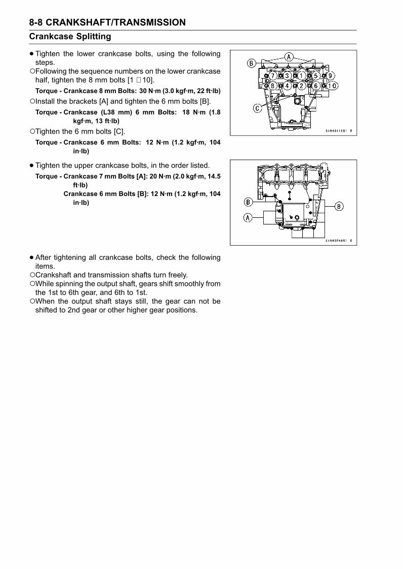
8-8 CRANKSHAFT/TRANSMISSIONCrankcase Splitting
•Tighten the lower crankcase bolts, using the followingsteps.Following the sequence numbers on the lower crankcasehalf, tighten the 8 mm bolts [1 ∼ 10].Torque - Crankcase 8 mm Bolts: 30 N·m (3.0 kgf·m, 22 ft·lb)Install the brackets [A] and tighten the 6 mm bolts [B].Torque - Crankcase (L38 mm) 6 mm Bolts: 18 N·m (1.8
kgf·m, 13 ft·lb)Tighten the 6 mm bolts [C].Torque - Crankcase 6 mm Bolts: 12 N·m (1.2 kgf·m, 104
in·lb)
•Tighten the upper crankcase bolts, in the order listed.Torque - Crankcase 7 mm Bolts [A]: 20 N·m (2.0 kgf·m, 14.5
ft·lb)Crankcase 6 mm Bolts [B]: 12 N·m (1.2 kgf·m, 104in·lb)
•After tightening all crankcase bolts, check the followingitems.Crankshaft and transmission shafts turn freely.While spinning the output shaft, gears shift smoothly fromthe 1st to 6th gear, and 6th to 1st.When the output shaft stays still, the gear can not beshifted to 2nd gear or other higher gear positions.
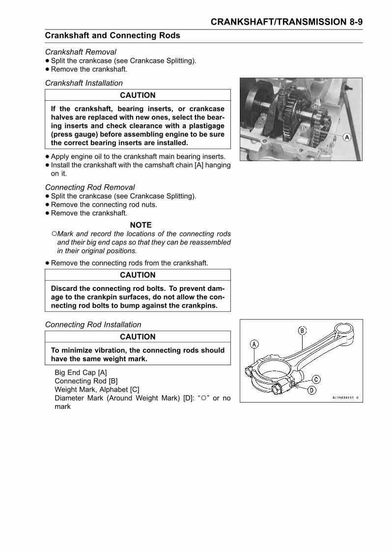
CRANKSHAFT/TRANSMISSION 8-9Crankshaft and Connecting Rods
Crankshaft Removal•Split the crankcase (see Crankcase Splitting).• Remove the crankshaft.Crankshaft Installation
CAUTIONIf the crankshaft, bearing inserts, or crankcasehalves are replaced with new ones, select the bear-ing inserts and check clearance with a plastigage(press gauge) before assembling engine to be surethe correct bearing inserts are installed.
•Apply engine oil to the crankshaft main bearing inserts.• Install the crankshaft with the camshaft chain [A] hangingon it.
Connecting Rod Removal•Split the crankcase (see Crankcase Splitting).• Remove the connecting rod nuts.•Remove the crankshaft.
NOTEMark and record the locations of the connecting rodsand their big end caps so that they can be reassembledin their original positions.
•Remove the connecting rods from the crankshaft.CAUTION
Discard the connecting rod bolts. To prevent dam-age to the crankpin surfaces, do not allow the con-necting rod bolts to bump against the crankpins.
Connecting Rod InstallationCAUTION
To minimize vibration, the connecting rods shouldhave the same weight mark.
Big End Cap [A]Connecting Rod [B]Weight Mark, Alphabet [C]Diameter Mark (Around Weight Mark) [D]: “” or nomark
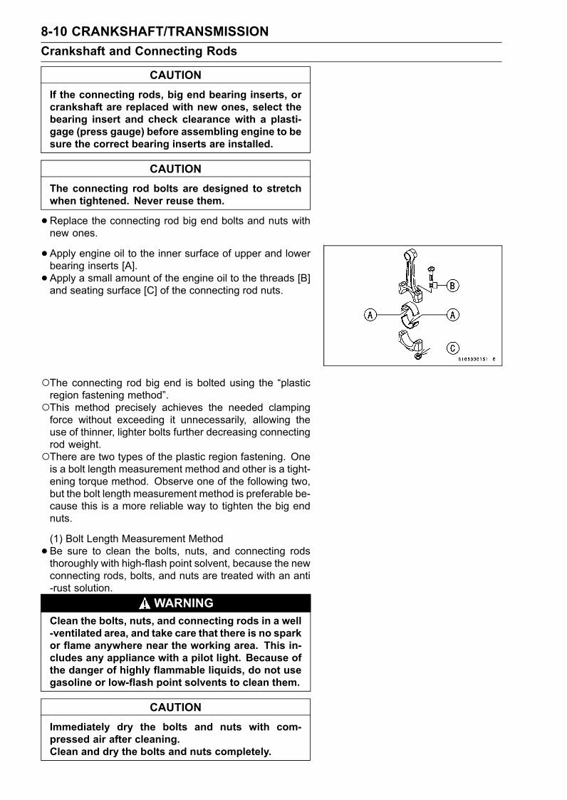
8-10 CRANKSHAFT/TRANSMISSIONCrankshaft and Connecting Rods
CAUTIONIf the connecting rods, big end bearing inserts, orcrankshaft are replaced with new ones, select thebearing insert and check clearance with a plasti-gage (press gauge) before assembling engine to besure the correct bearing inserts are installed.
CAUTIONThe connecting rod bolts are designed to stretchwhen tightened. Never reuse them.
•Replace the connecting rod big end bolts and nuts withnew ones.
• Apply engine oil to the inner surface of upper and lowerbearing inserts [A].• Apply a small amount of the engine oil to the threads [B]and seating surface [C] of the connecting rod nuts.
The connecting rod big end is bolted using the “plasticregion fastening method”.This method precisely achieves the needed clampingforce without exceeding it unnecessarily, allowing theuse of thinner, lighter bolts further decreasing connectingrod weight.There are two types of the plastic region fastening. Oneis a bolt length measurement method and other is a tight-ening torque method. Observe one of the following two,but the bolt length measurement method is preferable be-cause this is a more reliable way to tighten the big endnuts.
(1) Bolt Length Measurement Method•Be sure to clean the bolts, nuts, and connecting rodsthoroughly with high-flash point solvent, because the newconnecting rods, bolts, and nuts are treated with an anti-rust solution.
WARNINGClean the bolts, nuts, and connecting rods in a well-ventilated area, and take care that there is no sparkor flame anywhere near the working area. This in-cludes any appliance with a pilot light. Because ofthe danger of highly flammable liquids, do not usegasoline or low-flash point solvents to clean them.
CAUTIONImmediately dry the bolts and nuts with com-pressed air after cleaning.Clean and dry the bolts and nuts completely.
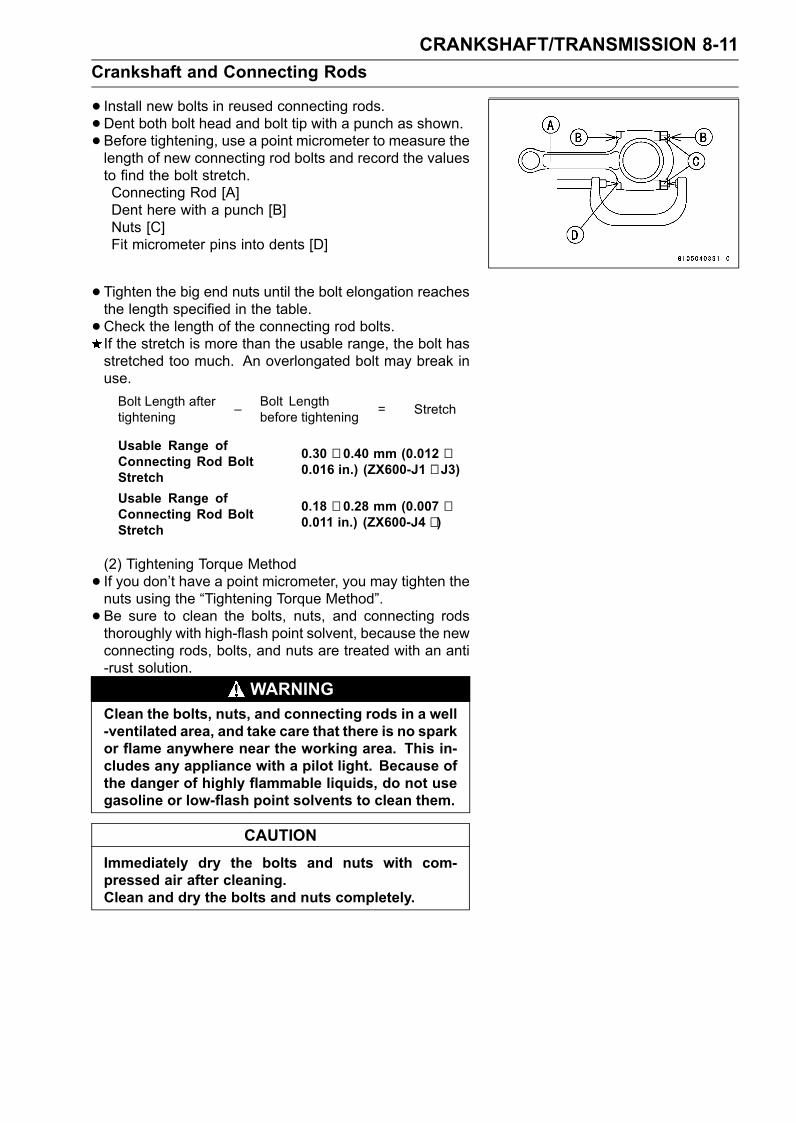
CRANKSHAFT/TRANSMISSION 8-11Crankshaft and Connecting Rods
• Install new bolts in reused connecting rods.•Dent both bolt head and bolt tip with a punch as shown.• Before tightening, use a point micrometer to measure thelength of new connecting rod bolts and record the valuesto find the bolt stretch.Connecting Rod [A]Dent here with a punch [B]Nuts [C]Fit micrometer pins into dents [D]
• Tighten the big end nuts until the bolt elongation reachesthe length specified in the table.•Check the length of the connecting rod bolts.If the stretch is more than the usable range, the bolt hasstretched too much. An overlongated bolt may break inuse.Bolt Length aftertightening – Bolt Length
before tightening = Stretch
Usable Range ofConnecting Rod BoltStretch
0.30 ∼ 0.40 mm (0.012 ∼0.016 in.) (ZX600-J1 ∼ J3)
Usable Range ofConnecting Rod BoltStretch
0.18 ∼ 0.28 mm (0.007 ∼0.011 in.) (ZX600-J4 ∼ )
(2) Tightening Torque Method• If you don’t have a point micrometer, you may tighten thenuts using the “Tightening Torque Method”.• Be sure to clean the bolts, nuts, and connecting rodsthoroughly with high-flash point solvent, because the newconnecting rods, bolts, and nuts are treated with an anti-rust solution.
WARNINGClean the bolts, nuts, and connecting rods in a well-ventilated area, and take care that there is no sparkor flame anywhere near the working area. This in-cludes any appliance with a pilot light. Because ofthe danger of highly flammable liquids, do not usegasoline or low-flash point solvents to clean them.
CAUTIONImmediately dry the bolts and nuts with com-pressed air after cleaning.Clean and dry the bolts and nuts completely.
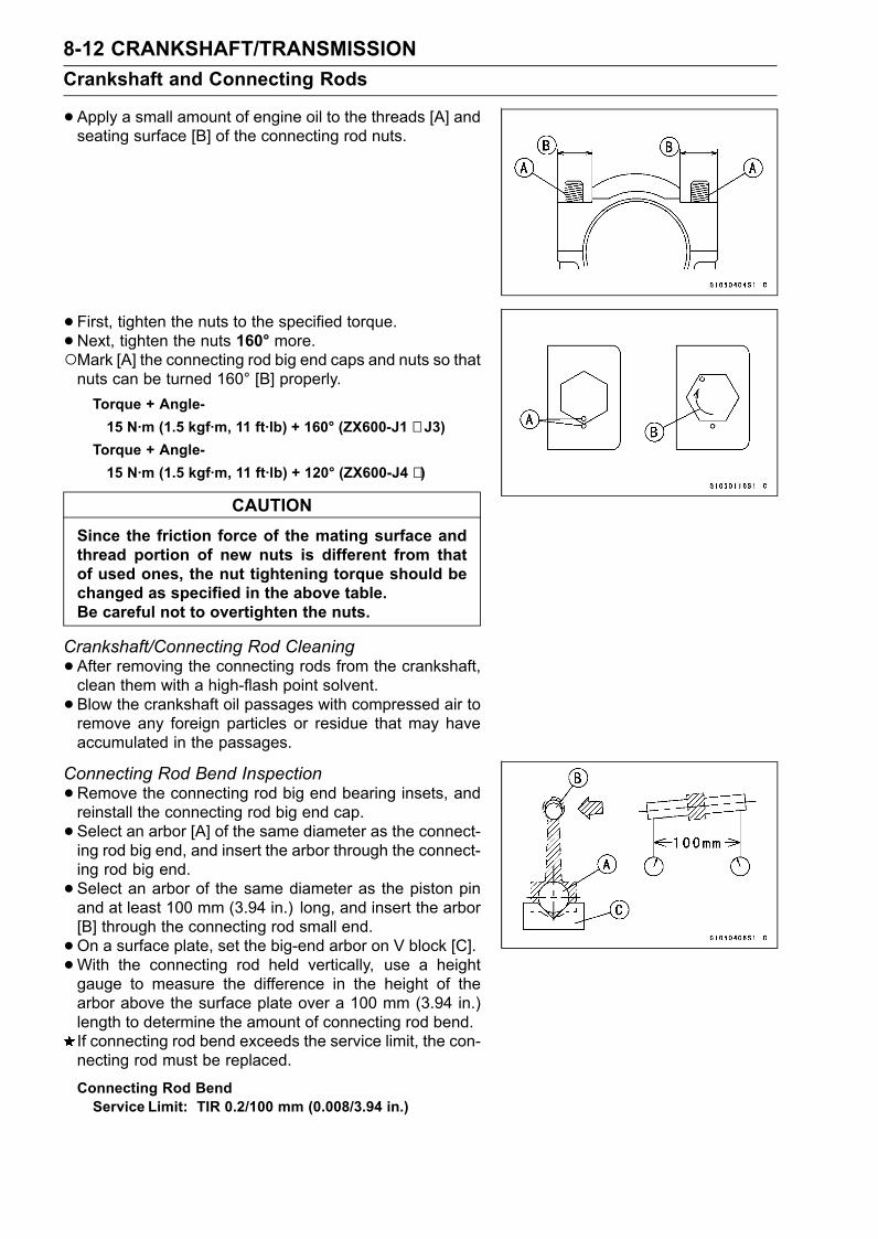
8-12 CRANKSHAFT/TRANSMISSIONCrankshaft and Connecting Rods
•Apply a small amount of engine oil to the threads [A] andseating surface [B] of the connecting rod nuts.
• First, tighten the nuts to the specified torque.•Next, tighten the nuts 160° more.Mark [A] the connecting rod big end caps and nuts so thatnuts can be turned 160° [B] properly.Torque + Angle-15 N·m (1.5 kgf·m, 11 ft·lb) + 160° (ZX600-J1 ∼ J3)
Torque + Angle-15 N·m (1.5 kgf·m, 11 ft·lb) + 120° (ZX600-J4 ∼ )
CAUTIONSince the friction force of the mating surface andthread portion of new nuts is different from thatof used ones, the nut tightening torque should bechanged as specified in the above table.Be careful not to overtighten the nuts.
Crankshaft/Connecting Rod Cleaning•After removing the connecting rods from the crankshaft,clean them with a high-flash point solvent.• Blow the crankshaft oil passages with compressed air toremove any foreign particles or residue that may haveaccumulated in the passages.
Connecting Rod Bend Inspection•Remove the connecting rod big end bearing insets, andreinstall the connecting rod big end cap.• Select an arbor [A] of the same diameter as the connect-ing rod big end, and insert the arbor through the connect-ing rod big end.• Select an arbor of the same diameter as the piston pinand at least 100 mm (3.94 in.) long, and insert the arbor[B] through the connecting rod small end.•On a surface plate, set the big-end arbor on V block [C].•With the connecting rod held vertically, use a heightgauge to measure the difference in the height of thearbor above the surface plate over a 100 mm (3.94 in.)length to determine the amount of connecting rod bend.If connecting rod bend exceeds the service limit, the con-necting rod must be replaced.
Connecting Rod BendService Limit: TIR 0.2/100 mm (0.008/3.94 in.)
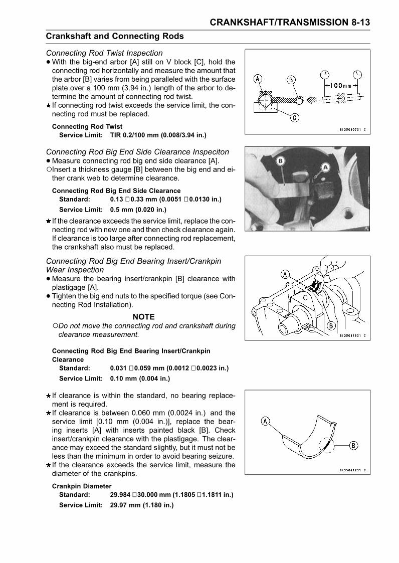
CRANKSHAFT/TRANSMISSION 8-13Crankshaft and Connecting Rods
Connecting Rod Twist Inspection•With the big-end arbor [A] still on V block [C], hold theconnecting rod horizontally and measure the amount thatthe arbor [B] varies from being paralleled with the surfaceplate over a 100 mm (3.94 in.) length of the arbor to de-termine the amount of connecting rod twist.If connecting rod twist exceeds the service limit, the con-necting rod must be replaced.
Connecting Rod TwistService Limit: TIR 0.2/100 mm (0.008/3.94 in.)
Connecting Rod Big End Side Clearance Inspeciton•Measure connecting rod big end side clearance [A].Insert a thickness gauge [B] between the big end and ei-ther crank web to determine clearance.
Connecting Rod Big End Side ClearanceStandard: 0.13 ∼ 0.33 mm (0.0051 ∼ 0.0130 in.)Service Limit: 0.5 mm (0.020 in.)
If the clearance exceeds the service limit, replace the con-necting rod with new one and then check clearance again.If clearance is too large after connecting rod replacement,the crankshaft also must be replaced.
Connecting Rod Big End Bearing Insert/CrankpinWear Inspection•Measure the bearing insert/crankpin [B] clearance withplastigage [A].• Tighten the big end nuts to the specified torque (see Con-necting Rod Installation).
NOTEDo not move the connecting rod and crankshaft duringclearance measurement.
Connecting Rod Big End Bearing Insert/CrankpinClearanceStandard: 0.031 ∼ 0.059 mm (0.0012 ∼ 0.0023 in.)Service Limit: 0.10 mm (0.004 in.)
If clearance is within the standard, no bearing replace-ment is required.If clearance is between 0.060 mm (0.0024 in.) and theservice limit [0.10 mm (0.004 in.)], replace the bear-ing inserts [A] with inserts painted black [B]. Checkinsert/crankpin clearance with the plastigage. The clear-ance may exceed the standard slightly, but it must not beless than the minimum in order to avoid bearing seizure.If the clearance exceeds the service limit, measure thediameter of the crankpins.
Crankpin DiameterStandard: 29.984 ∼ 30.000 mm (1.1805 ∼ 1.1811 in.)Service Limit: 29.97 mm (1.180 in.)
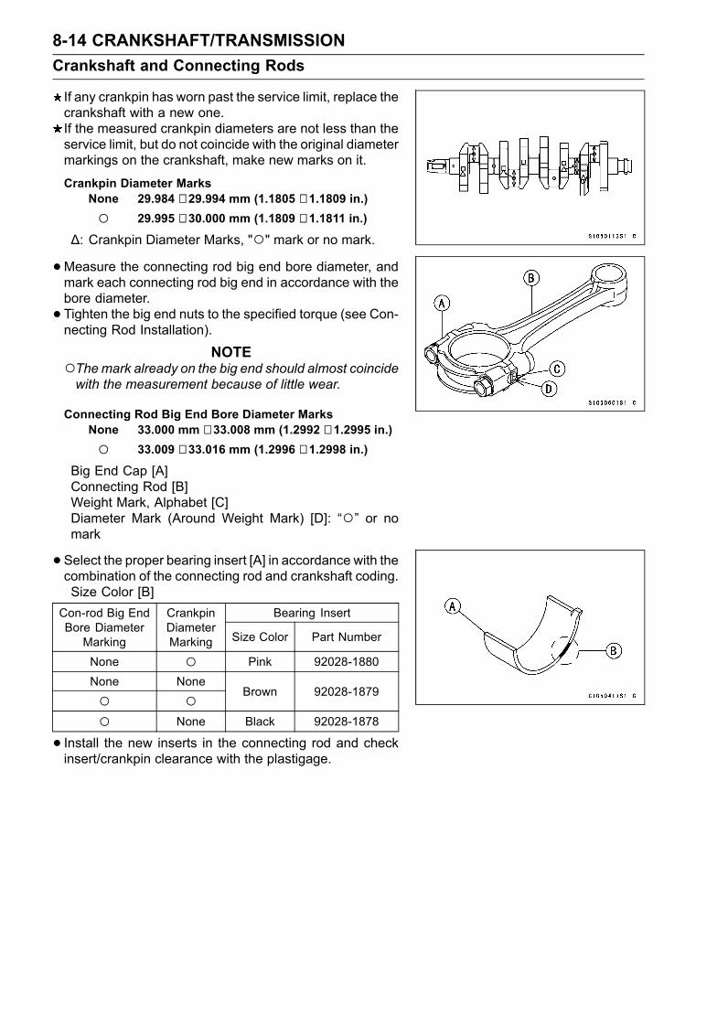
8-14 CRANKSHAFT/TRANSMISSIONCrankshaft and Connecting Rods
If any crankpin has worn past the service limit, replace thecrankshaft with a new one.If the measured crankpin diameters are not less than theservice limit, but do not coincide with the original diametermarkings on the crankshaft, make new marks on it.
Crankpin Diameter MarksNone 29.984 ∼ 29.994 mm (1.1805 ∼ 1.1809 in.)
29.995 ∼ 30.000 mm (1.1809 ∼ 1.1811 in.)
∆: Crankpin Diameter Marks, "" mark or no mark.•Measure the connecting rod big end bore diameter, andmark each connecting rod big end in accordance with thebore diameter.• Tighten the big end nuts to the specified torque (see Con-necting Rod Installation).
NOTEThemark already on the big end should almost coincidewith the measurement because of little wear.
Connecting Rod Big End Bore Diameter MarksNone 33.000 mm ∼ 33.008 mm (1.2992 ∼ 1.2995 in.)
33.009 ∼ 33.016 mm (1.2996 ∼ 1.2998 in.)
Big End Cap [A]Connecting Rod [B]Weight Mark, Alphabet [C]Diameter Mark (Around Weight Mark) [D]: “” or nomark
•Select the proper bearing insert [A] in accordance with thecombination of the connecting rod and crankshaft coding.Size Color [B]
Bearing InsertCon-rod Big EndBore Diameter
Marking
CrankpinDiameterMarking Size Color Part Number
None Pink 92028-1880None None
Brown 92028-1879
None Black 92028-1878
• Install the new inserts in the connecting rod and checkinsert/crankpin clearance with the plastigage.
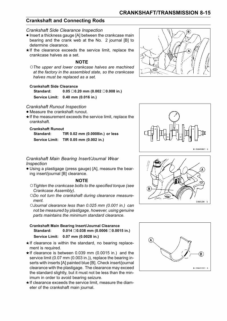
CRANKSHAFT/TRANSMISSION 8-15Crankshaft and Connecting Rods
Crankshaft Side Clearance Inspection• Insert a thickness gauge [A] between the crankcase mainbearing and the crank web at the No. 2 journal [B] todetermine clearance.If the clearance exceeds the service limit, replace thecrankcase halves as a set.
NOTEThe upper and lower crankcase halves are machinedat the factory in the assembled state, so the crankcasehalves must be replaced as a set.
Crankshaft Side ClearanceStandard: 0.05 ∼ 0.20 mm (0.002 ∼ 0.008 in.)Service Limit: 0.40 mm (0.016 in.)
Crankshaft Runout Inspection•Measure the crankshaft runout.If the measurement exceeds the service limit, replace thecrankshaft.
Crankshaft RunoutStandard: TIR 0.02 mm (0.0008in.) or lessService Limit: TIR 0.05 mm (0.002 in.)
Crankshaft Main Bearing Insert/Journal WearInspection•Using a plastigage (press gauge) [A], measure the bear-ing insert/journal [B] clearance.
NOTETighten the crankcase bolts to the specified torque (seeCrankcase Assembly).Do not turn the crankshaft during clearance measure-ment.Journal clearance less than 0.025 mm (0.001 in.) cannot bemeasured by plastigage, however, using genuineparts maintains the minimum standard clearance.
Crankshaft Main Bearing Insert/Journal ClearanceStandard: 0.014 ∼ 0.038 mm (0.0006 ∼ 0.0015 in.)Service Limit: 0.07 mm (0.0028 in.)
If clearance is within the standard, no bearing replace-ment is required.If clearance is between 0.039 mm (0.0015 in.) and theservice limit (0.07 mm (0.003 in.)), replace the bearing in-serts with inserts [A] painted blue [B]. Check insert/journalclearance with the plastigage. The clearancemay exceedthe standard slightly, but it must not be less than the min-imum in order to avoid bearing seizure.If clearance exceeds the service limit, measure the diam-eter of the crankshaft main journal.
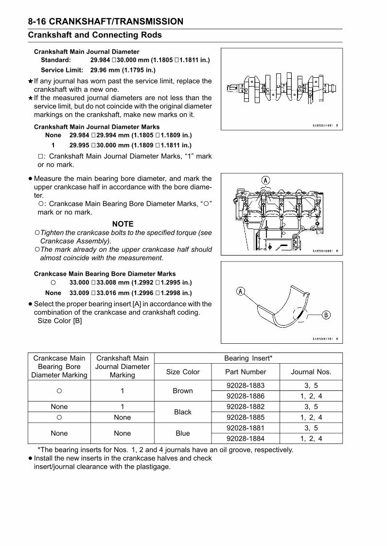
8-16 CRANKSHAFT/TRANSMISSIONCrankshaft and Connecting Rods
Crankshaft Main Journal DiameterStandard: 29.984 ∼ 30.000 mm (1.1805 ∼ 1.1811 in.)Service Limit: 29.96 mm (1.1795 in.)
If any journal has worn past the service limit, replace thecrankshaft with a new one.If the measured journal diameters are not less than theservice limit, but do not coincide with the original diametermarkings on the crankshaft, make new marks on it.
Crankshaft Main Journal Diameter MarksNone 29.984 ∼ 29.994 mm (1.1805 ∼ 1.1809 in.)1 29.995 ∼ 30.000 mm (1.1809 ∼ 1.1811 in.)
: Crankshaft Main Journal Diameter Marks, “1” markor no mark.
•Measure the main bearing bore diameter, and mark theupper crankcase half in accordance with the bore diame-ter.: Crankcase Main Bearing Bore Diameter Marks, “”mark or no mark.
NOTETighten the crankcase bolts to the specified torque (seeCrankcase Assembly).The mark already on the upper crankcase half shouldalmost coincide with the measurement.
Crankcase Main Bearing Bore Diameter Marks 33.000 ∼ 33.008 mm (1.2992 ∼ 1.2995 in.)None 33.009 ∼ 33.016 mm (1.2996 ∼ 1.2998 in.)
•Select the proper bearing insert [A] in accordance with thecombination of the crankcase and crankshaft coding.Size Color [B]
Bearing Insert*Crankcase MainBearing Bore
Diameter Marking
Crankshaft MainJournal Diameter
Marking Size Color Part Number Journal Nos.
92028-1883 3, 5 1 Brown92028-1886 1, 2, 4
None 1 92028-1882 3, 5 None
Black92028-1885 1, 2, 492028-1881 3, 5
None None Blue92028-1884 1, 2, 4
*The bearing inserts for Nos. 1, 2 and 4 journals have an oil groove, respectively.• Install the new inserts in the crankcase halves and checkinsert/journal clearance with the plastigage.
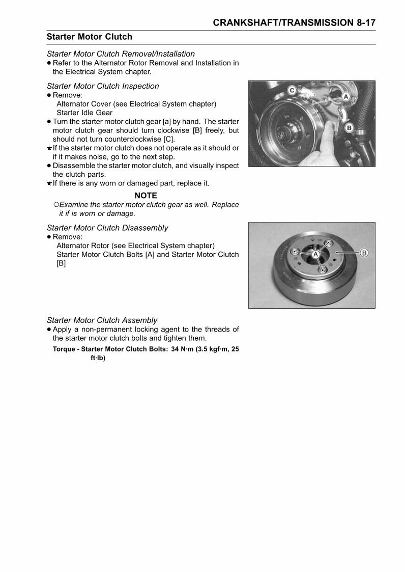
CRANKSHAFT/TRANSMISSION 8-17Starter Motor Clutch
Starter Motor Clutch Removal/Installation•Refer to the Alternator Rotor Removal and Installation inthe Electrical System chapter.
Starter Motor Clutch Inspection•Remove:Alternator Cover (see Electrical System chapter)Starter Idle Gear• Turn the starter motor clutch gear [a] by hand. The startermotor clutch gear should turn clockwise [B] freely, butshould not turn counterclockwise [C].If the starter motor clutch does not operate as it should orif it makes noise, go to the next step.•Disassemble the starter motor clutch, and visually inspectthe clutch parts.If there is any worn or damaged part, replace it.
NOTEExamine the starter motor clutch gear as well. Replaceit if is worn or damage.
Starter Motor Clutch Disassembly•Remove:Alternator Rotor (see Electrical System chapter)Starter Motor Clutch Bolts [A] and Starter Motor Clutch[B]
Starter Motor Clutch Assembly•Apply a non-permanent locking agent to the threads ofthe starter motor clutch bolts and tighten them.Torque - Starter Motor Clutch Bolts: 34 N·m (3.5 kgf·m, 25
ft·lb)
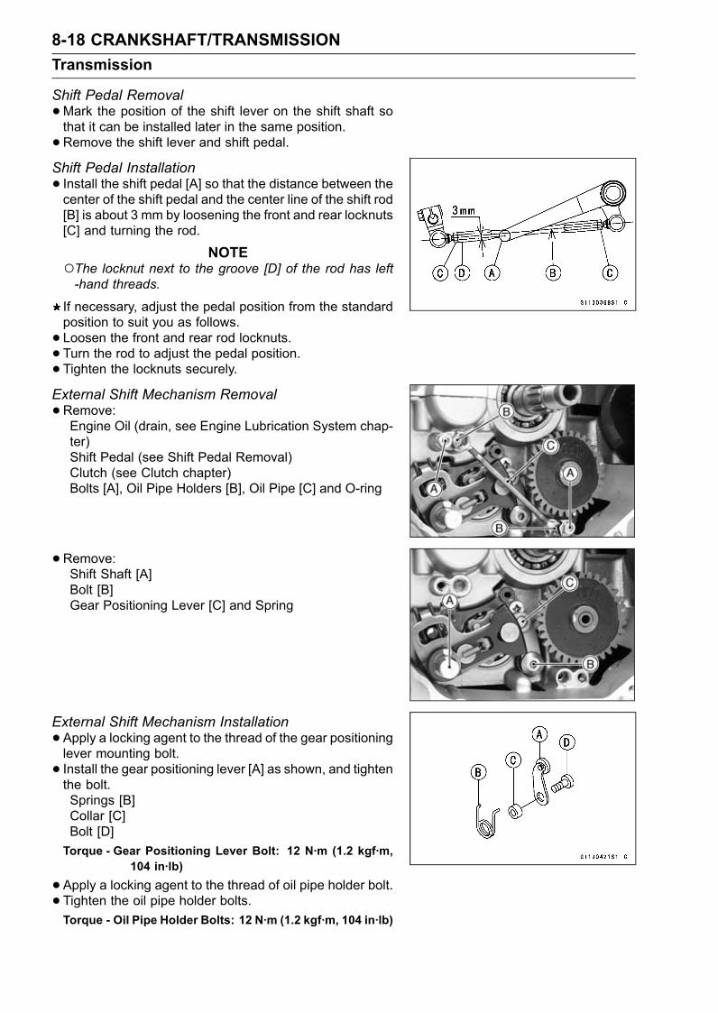
8-18 CRANKSHAFT/TRANSMISSIONTransmission
Shift Pedal Removal•Mark the position of the shift lever on the shift shaft sothat it can be installed later in the same position.•Remove the shift lever and shift pedal.Shift Pedal Installation• Install the shift pedal [A] so that the distance between thecenter of the shift pedal and the center line of the shift rod[B] is about 3 mm by loosening the front and rear locknuts[C] and turning the rod.
NOTEThe locknut next to the groove [D] of the rod has left-hand threads.
If necessary, adjust the pedal position from the standardposition to suit you as follows.• Loosen the front and rear rod locknuts.• Turn the rod to adjust the pedal position.• Tighten the locknuts securely.External Shift Mechanism Removal•Remove:Engine Oil (drain, see Engine Lubrication System chap-ter)Shift Pedal (see Shift Pedal Removal)Clutch (see Clutch chapter)Bolts [A], Oil Pipe Holders [B], Oil Pipe [C] and O-ring
•Remove:Shift Shaft [A]Bolt [B]Gear Positioning Lever [C] and Spring
External Shift Mechanism Installation•Apply a locking agent to the thread of the gear positioninglever mounting bolt.• Install the gear positioning lever [A] as shown, and tightenthe bolt.Springs [B]Collar [C]Bolt [D]Torque - Gear Positioning Lever Bolt: 12 N·m (1.2 kgf·m,
104 in·lb)
•Apply a locking agent to the thread of oil pipe holder bolt.• Tighten the oil pipe holder bolts.Torque - Oil Pipe Holder Bolts: 12 N·m (1.2 kgf·m, 104 in·lb)
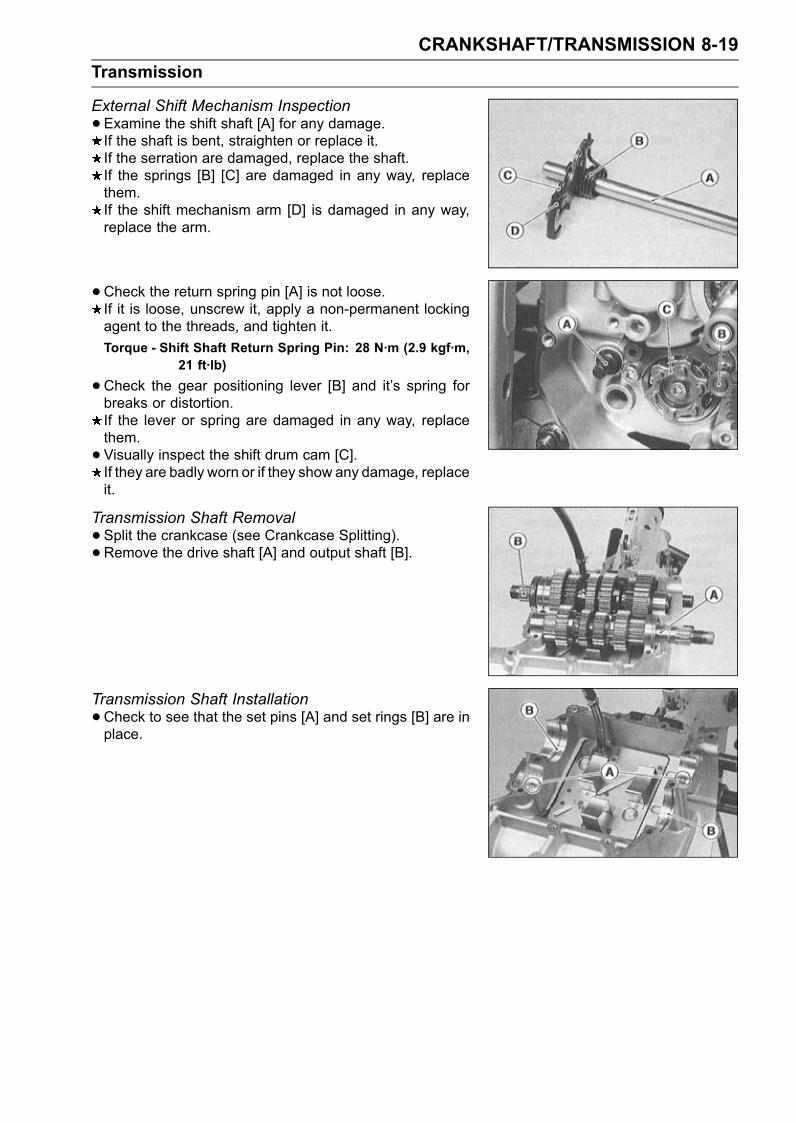
CRANKSHAFT/TRANSMISSION 8-19Transmission
External Shift Mechanism Inspection•Examine the shift shaft [A] for any damage.If the shaft is bent, straighten or replace it.If the serration are damaged, replace the shaft.If the springs [B] [C] are damaged in any way, replacethem.If the shift mechanism arm [D] is damaged in any way,replace the arm.
•Check the return spring pin [A] is not loose.If it is loose, unscrew it, apply a non-permanent lockingagent to the threads, and tighten it.Torque - Shift Shaft Return Spring Pin: 28 N·m (2.9 kgf·m,
21 ft·lb)
•Check the gear positioning lever [B] and it’s spring forbreaks or distortion.If the lever or spring are damaged in any way, replacethem.•Visually inspect the shift drum cam [C].If they are badly worn or if they show any damage, replaceit.
Transmission Shaft Removal•Split the crankcase (see Crankcase Splitting).• Remove the drive shaft [A] and output shaft [B].
Transmission Shaft Installation•Check to see that the set pins [A] and set rings [B] are inplace.
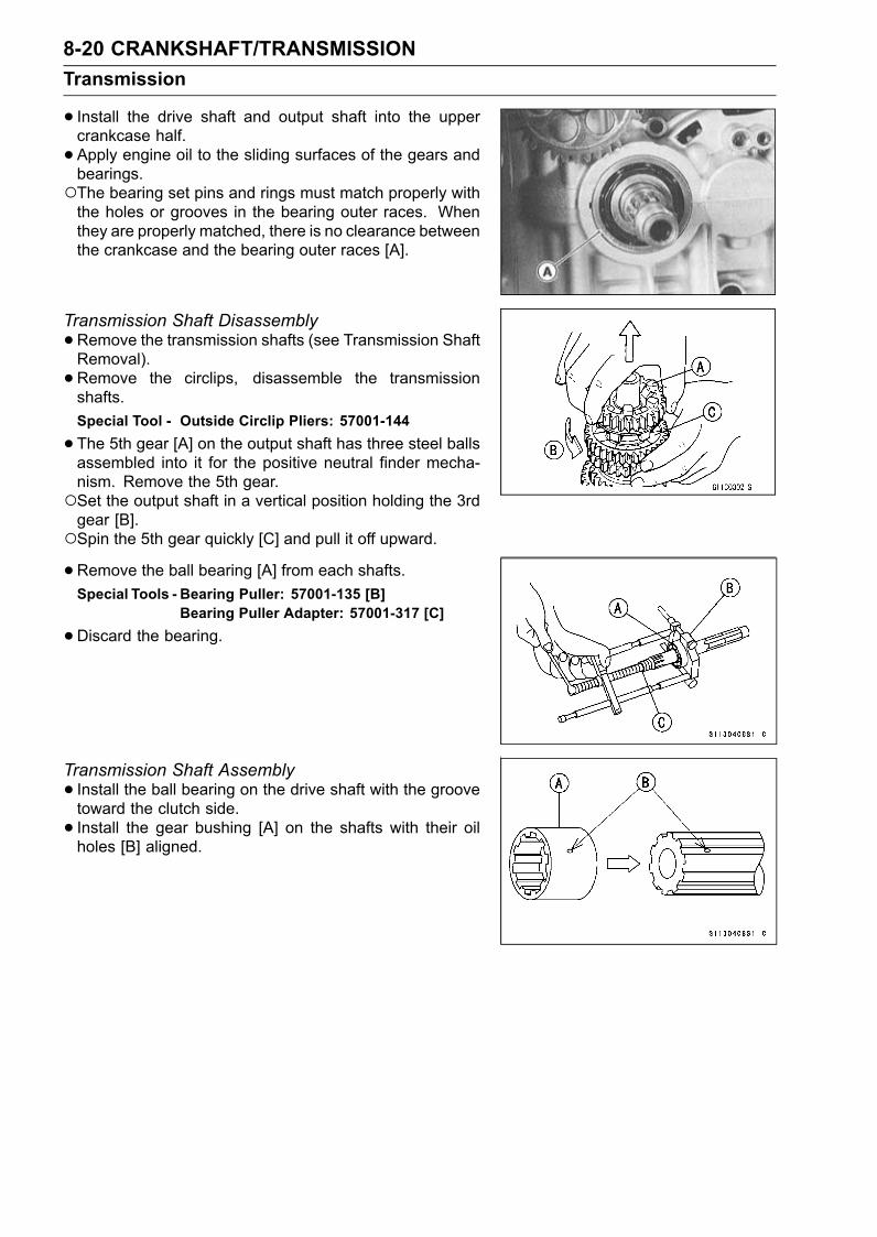
8-20 CRANKSHAFT/TRANSMISSIONTransmission
• Install the drive shaft and output shaft into the uppercrankcase half.• Apply engine oil to the sliding surfaces of the gears andbearings.The bearing set pins and rings must match properly withthe holes or grooves in the bearing outer races. Whenthey are properly matched, there is no clearance betweenthe crankcase and the bearing outer races [A].
Transmission Shaft Disassembly•Remove the transmission shafts (see Transmission ShaftRemoval).• Remove the circlips, disassemble the transmissionshafts.Special Tool - Outside Circlip Pliers: 57001-144
•The 5th gear [A] on the output shaft has three steel ballsassembled into it for the positive neutral finder mecha-nism. Remove the 5th gear.Set the output shaft in a vertical position holding the 3rdgear [B].Spin the 5th gear quickly [C] and pull it off upward.•Remove the ball bearing [A] from each shafts.Special Tools - Bearing Puller: 57001-135 [B]
Bearing Puller Adapter: 57001-317 [C]
•Discard the bearing.
Transmission Shaft Assembly• Install the ball bearing on the drive shaft with the groovetoward the clutch side.• Install the gear bushing [A] on the shafts with their oilholes [B] aligned.
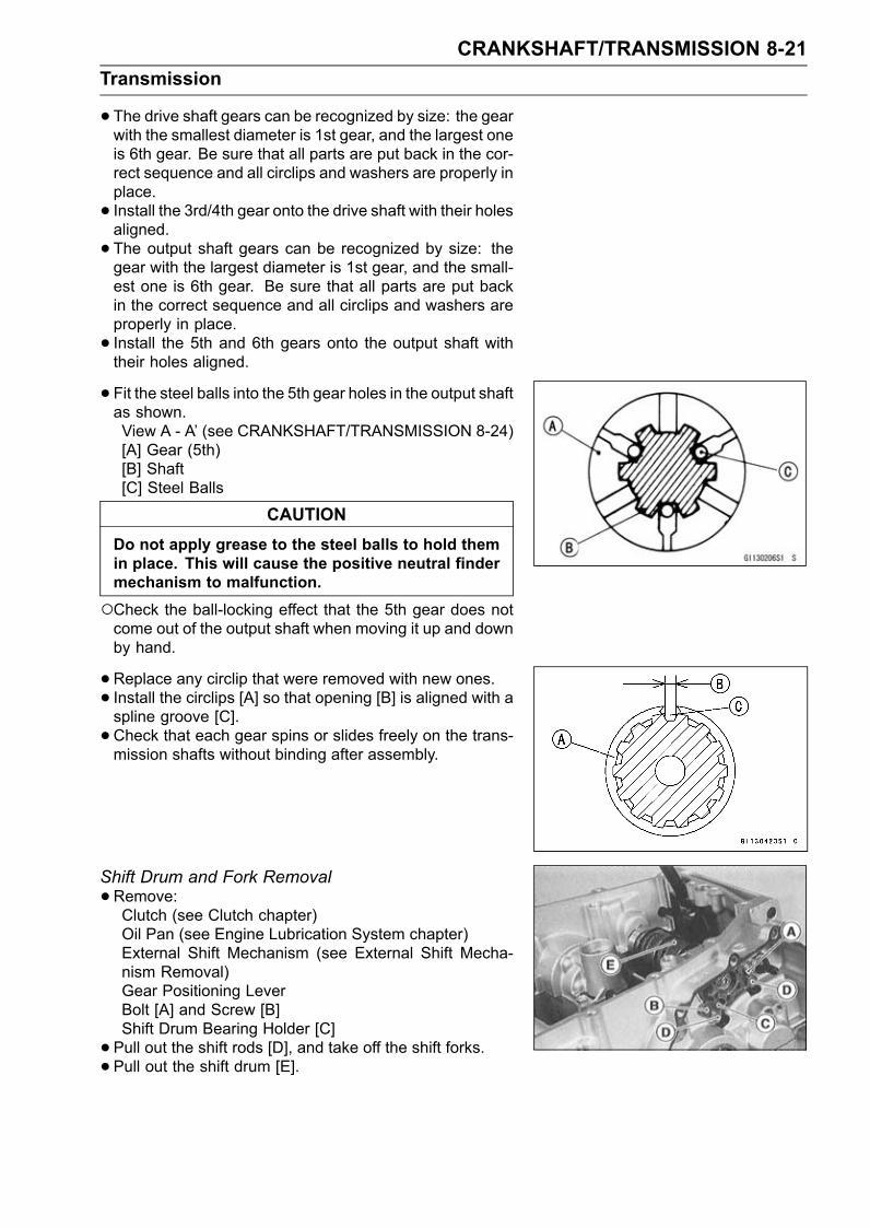
CRANKSHAFT/TRANSMISSION 8-21Transmission
•The drive shaft gears can be recognized by size: the gearwith the smallest diameter is 1st gear, and the largest oneis 6th gear. Be sure that all parts are put back in the cor-rect sequence and all circlips and washers are properly inplace.• Install the 3rd/4th gear onto the drive shaft with their holesaligned.• The output shaft gears can be recognized by size: thegear with the largest diameter is 1st gear, and the small-est one is 6th gear. Be sure that all parts are put backin the correct sequence and all circlips and washers areproperly in place.• Install the 5th and 6th gears onto the output shaft withtheir holes aligned.
• Fit the steel balls into the 5th gear holes in the output shaftas shown.View A - A’ (see CRANKSHAFT/TRANSMISSION 8-24)[A] Gear (5th)[B] Shaft[C] Steel Balls
CAUTIONDo not apply grease to the steel balls to hold themin place. This will cause the positive neutral findermechanism to malfunction.
Check the ball-locking effect that the 5th gear does notcome out of the output shaft when moving it up and downby hand.
•Replace any circlip that were removed with new ones.• Install the circlips [A] so that opening [B] is aligned with aspline groove [C].• Check that each gear spins or slides freely on the trans-mission shafts without binding after assembly.
Shift Drum and Fork Removal•Remove:Clutch (see Clutch chapter)Oil Pan (see Engine Lubrication System chapter)External Shift Mechanism (see External Shift Mecha-nism Removal)Gear Positioning LeverBolt [A] and Screw [B]Shift Drum Bearing Holder [C]• Pull out the shift rods [D], and take off the shift forks.• Pull out the shift drum [E].
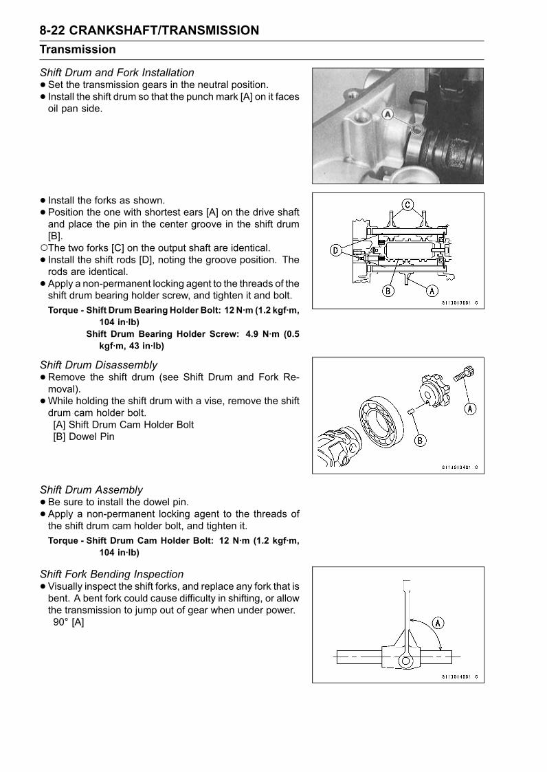
8-22 CRANKSHAFT/TRANSMISSIONTransmission
Shift Drum and Fork Installation•Set the transmission gears in the neutral position.• Install the shift drum so that the punch mark [A] on it facesoil pan side.
• Install the forks as shown.• Position the one with shortest ears [A] on the drive shaftand place the pin in the center groove in the shift drum[B].The two forks [C] on the output shaft are identical.• Install the shift rods [D], noting the groove position. Therods are identical.• Apply a non-permanent locking agent to the threads of theshift drum bearing holder screw, and tighten it and bolt.Torque - Shift DrumBearing Holder Bolt: 12 N·m (1.2 kgf·m,
104 in·lb)Shift Drum Bearing Holder Screw: 4.9 N·m (0.5kgf·m, 43 in·lb)
Shift Drum Disassembly•Remove the shift drum (see Shift Drum and Fork Re-moval).•While holding the shift drum with a vise, remove the shiftdrum cam holder bolt.[A] Shift Drum Cam Holder Bolt[B] Dowel Pin
Shift Drum Assembly•Be sure to install the dowel pin.• Apply a non-permanent locking agent to the threads ofthe shift drum cam holder bolt, and tighten it.Torque - Shift Drum Cam Holder Bolt: 12 N·m (1.2 kgf·m,
104 in·lb)
Shift Fork Bending Inspection•Visually inspect the shift forks, and replace any fork that isbent. A bent fork could cause difficulty in shifting, or allowthe transmission to jump out of gear when under power.90° [A]
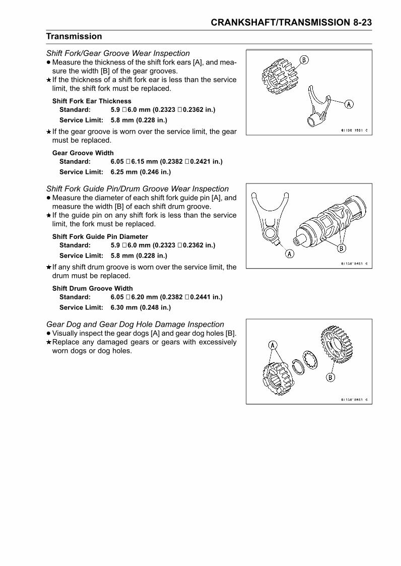
CRANKSHAFT/TRANSMISSION 8-23Transmission
Shift Fork/Gear Groove Wear Inspection•Measure the thickness of the shift fork ears [A], and mea-sure the width [B] of the gear grooves.If the thickness of a shift fork ear is less than the servicelimit, the shift fork must be replaced.
Shift Fork Ear ThicknessStandard: 5.9 ∼ 6.0 mm (0.2323 ∼ 0.2362 in.)Service Limit: 5.8 mm (0.228 in.)
If the gear groove is worn over the service limit, the gearmust be replaced.
Gear Groove WidthStandard: 6.05 ∼ 6.15 mm (0.2382 ∼ 0.2421 in.)Service Limit: 6.25 mm (0.246 in.)
Shift Fork Guide Pin/Drum Groove Wear Inspection•Measure the diameter of each shift fork guide pin [A], andmeasure the width [B] of each shift drum groove.If the guide pin on any shift fork is less than the servicelimit, the fork must be replaced.
Shift Fork Guide Pin DiameterStandard: 5.9 ∼ 6.0 mm (0.2323 ∼ 0.2362 in.)Service Limit: 5.8 mm (0.228 in.)
If any shift drum groove is worn over the service limit, thedrum must be replaced.
Shift Drum Groove WidthStandard: 6.05 ∼ 6.20 mm (0.2382 ∼ 0.2441 in.)Service Limit: 6.30 mm (0.248 in.)
Gear Dog and Gear Dog Hole Damage Inspection•Visually inspect the gear dogs [A] and gear dog holes [B].Replace any damaged gears or gears with excessivelyworn dogs or dog holes.
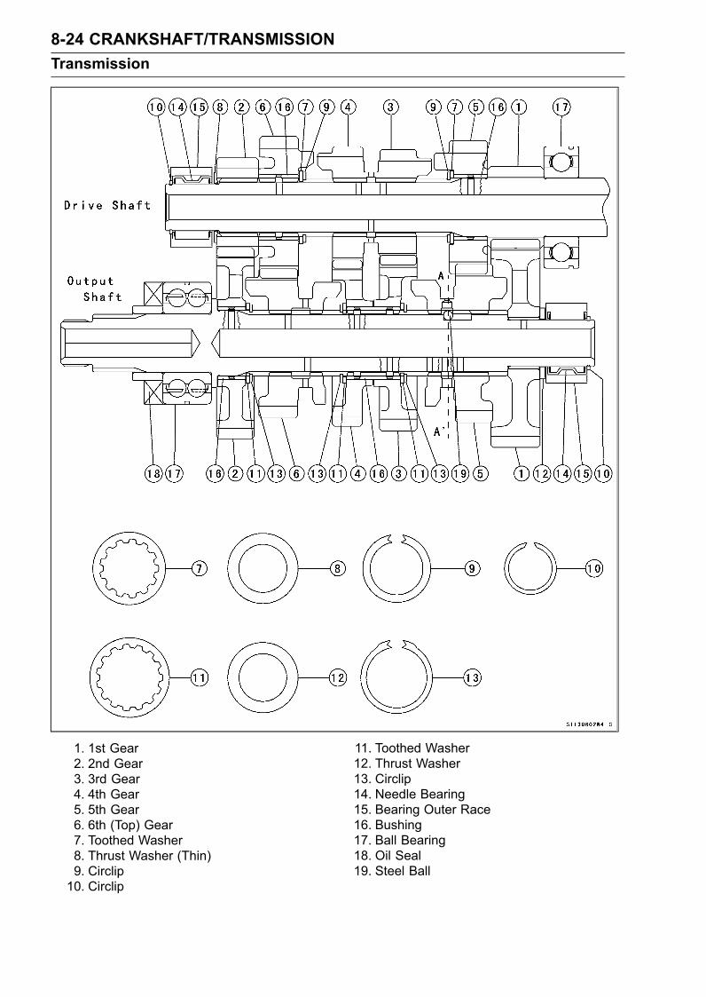
8-24 CRANKSHAFT/TRANSMISSIONTransmission
1. 1st Gear2. 2nd Gear3. 3rd Gear4. 4th Gear5. 5th Gear6. 6th (Top) Gear7. Toothed Washer8. Thrust Washer (Thin)9. Circlip10. Circlip
11. Toothed Washer12. Thrust Washer13. Circlip14. Needle Bearing15. Bearing Outer Race16. Bushing17. Ball Bearing18. Oil Seal19. Steel Ball
WHEELS/TIRES 9-1
9
Wheels/TiresTable of Contents
Exploded View........................................................................................................................ 9-2Specifications ......................................................................................................................... 9-3Wheels (Rims) ........................................................................................................................ 9-4
Front Wheel Removal ....................................................................................................... 9-4Front Wheel Installation .................................................................................................... 9-4Rear Wheel Removal........................................................................................................ 9-5Rear Wheel Installation..................................................................................................... 9-6Wheel Inspection .............................................................................................................. 9-7Axle Inspection.................................................................................................................. 9-7Balance Inspection............................................................................................................ 9-7Balance Adjustment .......................................................................................................... 9-8Balance Weight Removal.................................................................................................. 9-8Balance Weight Installation............................................................................................... 9-8
Tires........................................................................................................................................ 9-11Air Pressure Inspection/Adjustment.................................................................................. 9-11Tire Inspection .................................................................................................................. 9-11Tire Removal..................................................................................................................... 9-12Tire Installation.................................................................................................................. 9-12Tire Repair ........................................................................................................................ 9-14
Hub Bearing............................................................................................................................ 9-15Hub Bearing Removal....................................................................................................... 9-15Hub Bearing Installation.................................................................................................... 9-15Hub Bearing Inspection..................................................................................................... 9-16Hub Bearing Lubrication ................................................................................................... 9-16
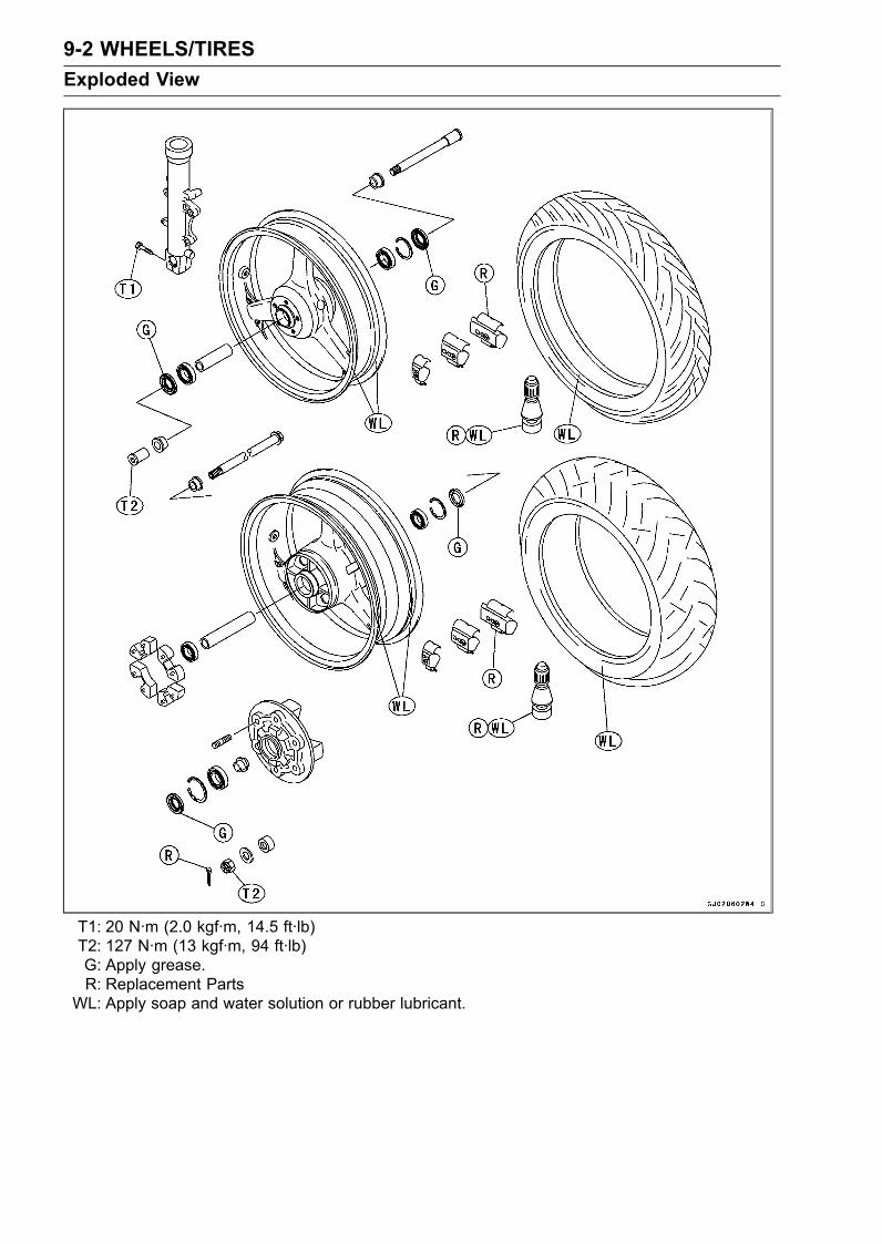
9-2 WHEELS/TIRESExploded View
T1: 20 N·m (2.0 kgf·m, 14.5 ft·lb)T2: 127 N·m (13 kgf·m, 94 ft·lb)G: Apply grease.R: Replacement Parts
WL: Apply soap and water solution or rubber lubricant.
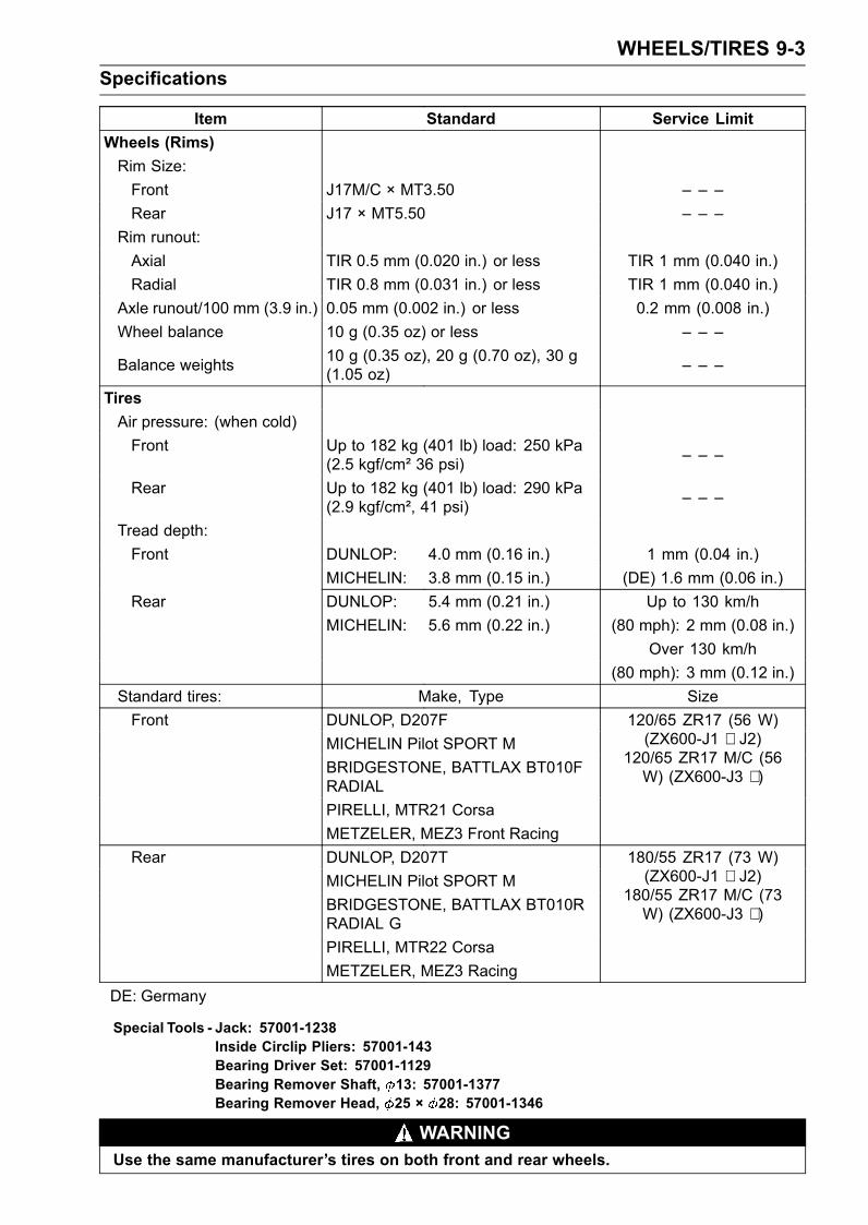
WHEELS/TIRES 9-3Specifications
Item Standard Service LimitWheels (Rims)Rim Size:Front J17M/C × MT3.50 – – –Rear J17 × MT5.50 – – –
Rim runout:Axial TIR 0.5 mm (0.020 in.) or less TIR 1 mm (0.040 in.)Radial TIR 0.8 mm (0.031 in.) or less TIR 1 mm (0.040 in.)
Axle runout/100 mm (3.9 in.) 0.05 mm (0.002 in.) or less 0.2 mm (0.008 in.)Wheel balance 10 g (0.35 oz) or less – – –
Balance weights 10 g (0.35 oz), 20 g (0.70 oz), 30 g(1.05 oz) – – –
TiresAir pressure: (when cold)Front Up to 182 kg (401 lb) load: 250 kPa
(2.5 kgf/cm² 36 psi) – – –
Rear Up to 182 kg (401 lb) load: 290 kPa(2.9 kgf/cm², 41 psi) – – –
Tread depth:Front DUNLOP: 4.0 mm (0.16 in.) 1 mm (0.04 in.)
MICHELIN: 3.8 mm (0.15 in.) (DE) 1.6 mm (0.06 in.)Rear DUNLOP: 5.4 mm (0.21 in.) Up to 130 km/h
MICHELIN: 5.6 mm (0.22 in.) (80 mph): 2 mm (0.08 in.)Over 130 km/h
(80 mph): 3 mm (0.12 in.)Standard tires: Make, Type SizeFront DUNLOP, D207F
MICHELIN Pilot SPORT MBRIDGESTONE, BATTLAX BT010FRADIAL
120/65 ZR17 (56 W)(ZX600-J1 ∼ J2)
120/65 ZR17 M/C (56W) (ZX600-J3 ∼ )
PIRELLI, MTR21 CorsaMETZELER, MEZ3 Front Racing
Rear DUNLOP, D207TMICHELIN Pilot SPORT MBRIDGESTONE, BATTLAX BT010RRADIAL G
180/55 ZR17 (73 W)(ZX600-J1 ∼ J2)
180/55 ZR17 M/C (73W) (ZX600-J3 ∼ )
PIRELLI, MTR22 CorsaMETZELER, MEZ3 Racing
DE: Germany
Special Tools - Jack: 57001-1238Inside Circlip Pliers: 57001-143Bearing Driver Set: 57001-1129Bearing Remover Shaft, 13: 57001-1377Bearing Remover Head, 25 × 28: 57001-1346
WARNINGUse the same manufacturer’s tires on both front and rear wheels.
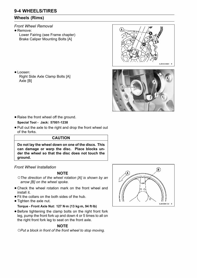
9-4 WHEELS/TIRESWheels (Rims)
Front Wheel Removal•Remove:Lower Fairing (see Frame chapter)Brake Caliper Mounting Bolts [A]
• Loosen:Right Side Axle Clamp Bolts [A]Axle [B]
•Raise the front wheel off the ground.Special Tool - Jack: 57001-1238
•Pull out the axle to the right and drop the front wheel outof the forks.
CAUTIONDo not lay the wheel down on one of the discs. Thiscan damage or warp the disc. Place blocks un-der the wheel so that the disc does not touch theground.
Front Wheel InstallationNOTE
The direction of the wheel rotation [A] is shown by anarrow [B] on the wheel spoke.
•Check the wheel rotation mark on the front wheel andinstall it.• Fit the collars on the both sides of the hub.• Tighten the axle nut.Torque - Front Axle Nut: 127 N·m (13 kg·m, 94 ft·lb)
•Before tightening the clamp bolts on the right front forkleg, pump the front fork up and down 4 or 5 times to all onthe right front fork leg to seat on the front axle.
NOTEPut a block in front of the front wheel to stop moving.
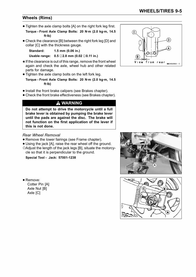
WHEELS/TIRES 9-5Wheels (Rims)
•Tighten the axle clamp bolts [A] on the right fork leg first.Torque - Front Axle Clamp Bolts: 20 N·m (2.0 kg·m, 14.5
ft·lb)
•Check the clearance [B] between the right fork leg [D] andcollar [C] with the thickness gauge.Standard: 1.5 mm (0.06 in.)Usable range: 0.5 ∼ 2.8 mm (0.02 ∼ 0.11 in.)
If the clearance is out of this range, remove the front wheelagain and check the axle, wheel hub and other relatedparts for damage.• Tighten the axle clamp bolts on the left fork leg.Torque - Front Axle Clamp Bolts: 20 N·m (2.0 kg·m, 14.5
ft·lb)
• Install the front brake calipers (see Brakes chapter).• Check the front brake effectiveness (see Brakes chapter).WARNING
Do not attempt to drive the motorcycle until a fullbrake lever is obtained by pumping the brake leveruntil the pads are against the disc. The brake willnot function on the first application of the lever ifthis is not done.
Rear Wheel Removal•Remove the lower fairings (see Frame chapter).• Using the jack [A], raise the rear wheel off the ground.Adjust the length of the jack legs [B], situate the motorcy-cle so that it is perpendicular to the ground.Special Tool - Jack: 57001-1238
•Remove:Cotter Pin [A]Axle Nut [B]Axle [C]
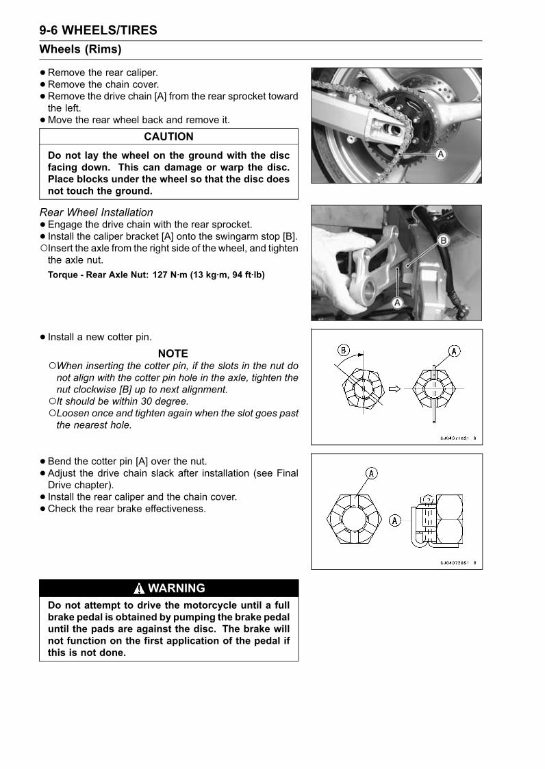
9-6 WHEELS/TIRESWheels (Rims)
•Remove the rear caliper.• Remove the chain cover.•Remove the drive chain [A] from the rear sprocket towardthe left.•Move the rear wheel back and remove it.
CAUTIONDo not lay the wheel on the ground with the discfacing down. This can damage or warp the disc.Place blocks under the wheel so that the disc doesnot touch the ground.
Rear Wheel Installation•Engage the drive chain with the rear sprocket.• Install the caliper bracket [A] onto the swingarm stop [B].Insert the axle from the right side of the wheel, and tightenthe axle nut.Torque - Rear Axle Nut: 127 N·m (13 kg·m, 94 ft·lb)
• Install a new cotter pin.NOTE
When inserting the cotter pin, if the slots in the nut donot align with the cotter pin hole in the axle, tighten thenut clockwise [B] up to next alignment.It should be within 30 degree.Loosen once and tighten again when the slot goes pastthe nearest hole.
•Bend the cotter pin [A] over the nut.• Adjust the drive chain slack after installation (see FinalDrive chapter).• Install the rear caliper and the chain cover.•Check the rear brake effectiveness.
WARNINGDo not attempt to drive the motorcycle until a fullbrake pedal is obtained by pumping the brake pedaluntil the pads are against the disc. The brake willnot function on the first application of the pedal ifthis is not done.
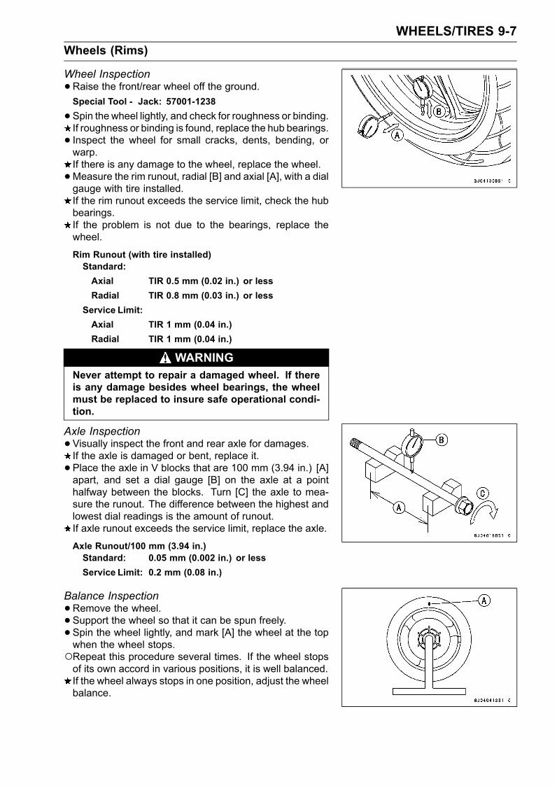
WHEELS/TIRES 9-7Wheels (Rims)
Wheel Inspection•Raise the front/rear wheel off the ground.Special Tool - Jack: 57001-1238
•Spin the wheel lightly, and check for roughness or binding.If roughness or binding is found, replace the hub bearings.• Inspect the wheel for small cracks, dents, bending, orwarp.If there is any damage to the wheel, replace the wheel.•Measure the rim runout, radial [B] and axial [A], with a dialgauge with tire installed.If the rim runout exceeds the service limit, check the hubbearings.If the problem is not due to the bearings, replace thewheel.
Rim Runout (with tire installed)Standard:Axial TIR 0.5 mm (0.02 in.) or lessRadial TIR 0.8 mm (0.03 in.) or less
Service Limit:Axial TIR 1 mm (0.04 in.)Radial TIR 1 mm (0.04 in.)
WARNINGNever attempt to repair a damaged wheel. If thereis any damage besides wheel bearings, the wheelmust be replaced to insure safe operational condi-tion.
Axle Inspection•Visually inspect the front and rear axle for damages.If the axle is damaged or bent, replace it.• Place the axle in V blocks that are 100 mm (3.94 in.) [A]apart, and set a dial gauge [B] on the axle at a pointhalfway between the blocks. Turn [C] the axle to mea-sure the runout. The difference between the highest andlowest dial readings is the amount of runout.If axle runout exceeds the service limit, replace the axle.
Axle Runout/100 mm (3.94 in.)Standard: 0.05 mm (0.002 in.) or lessService Limit: 0.2 mm (0.08 in.)
Balance Inspection•Remove the wheel.• Support the wheel so that it can be spun freely.• Spin the wheel lightly, and mark [A] the wheel at the topwhen the wheel stops.Repeat this procedure several times. If the wheel stopsof its own accord in various positions, it is well balanced.If the wheel always stops in one position, adjust the wheelbalance.
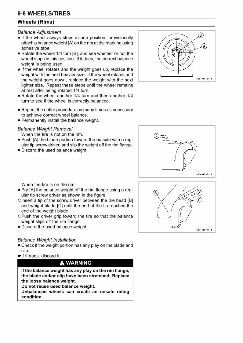
9-8 WHEELS/TIRESWheels (Rims)
Balance Adjustment• If the wheel always stops in one position, provisionallyattach a balanceweight [A] on the rim at themarking usingadhesive tape.•Rotate the wheel 1/4 turn [B], and see whether or not thewheel stops in this position. If it does, the correct balanceweight is being used.If the wheel rotates and the weight goes up, replace theweight with the next heavier size. If the wheel rotates andthe weight goes down, replace the weight with the nextlighter size. Repeat these steps until the wheel remainsat rest after being rotated 1/4 turn.•Rotate the wheel another 1/4 turn and then another 1/4turn to see if the wheel is correctly balanced.
•Repeat the entire procedure as many times as necessaryto achieve correct wheel balance.• Permanently install the balance weight.Balance Weight RemovalWhen the tire is not on the rim.• Push [A] the blade portion toward the outside with a reg-ular tip screw driver, and slip the weight off the rim flange.•Discard the used balance weight.
When the tire is on the rim.• Pry [A] the balance weight off the rim flange using a reg-ular tip screw driver as shown in the figure.Insert a tip of the screw driver between the tire bead [B]and weight blade [C] until the end of the tip reaches theend of the weight blade.Push the driver grip toward the tire so that the balanceweight slips off the rim flange.•Discard the used balance weight.Balance Weight Installation•Check if the weight portion has any play on the blade andclip.If it does, discard it.
WARNINGIf the balance weight has any play on the rim flange,the blade and/or clip have been stretched. Replacethe loose balance weight.Do not reuse used balance weight.Unbalanced wheels can create an unsafe ridingcondition.
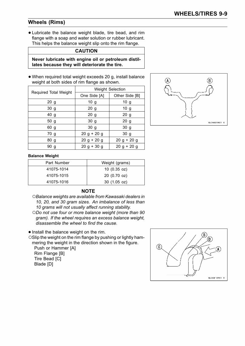
WHEELS/TIRES 9-9Wheels (Rims)
• Lubricate the balance weight blade, tire bead, and rimflange with a soap and water solution or rubber lubricant.This helps the balance weight slip onto the rim flange.
CAUTIONNever lubricate with engine oil or petroleum distil-lates because they will deteriorate the tire.
•When required total weight exceeds 20 g, install balanceweight at both sides of rim flange as shown.
Weight SelectionRequired Total Weight
One Side [A] Other Side [B]20 g 10 g 10 g30 g 20 g 10 g40 g 20 g 20 g50 g 30 g 20 g60 g 30 g 30 g70 g 20 g + 20 g 30 g80 g 20 g + 20 g 20 g + 20 g90 g 20 g + 30 g 20 g + 20 g
Balance WeightPart Number Weight (grams)41075-1014 10 (0.35 oz)41075-1015 20 (0.70 oz)41075-1016 30 (1.05 oz)
NOTEBalance weights are available from Kawasaki dealers in10, 20, and 30 gram sizes. An imbalance of less than10 grams will not usually affect running stability.Do not use four or more balance weight (more than 90gram). If the wheel requires an excess balance weight,disassemble the wheel to find the cause.
• Install the balance weight on the rim.Slip the weight on the rim flange by pushing or lightly ham-mering the weight in the direction shown in the figure.Push or Hammer [A]Rim Flange [B]Tire Bead [C]Blade [D]
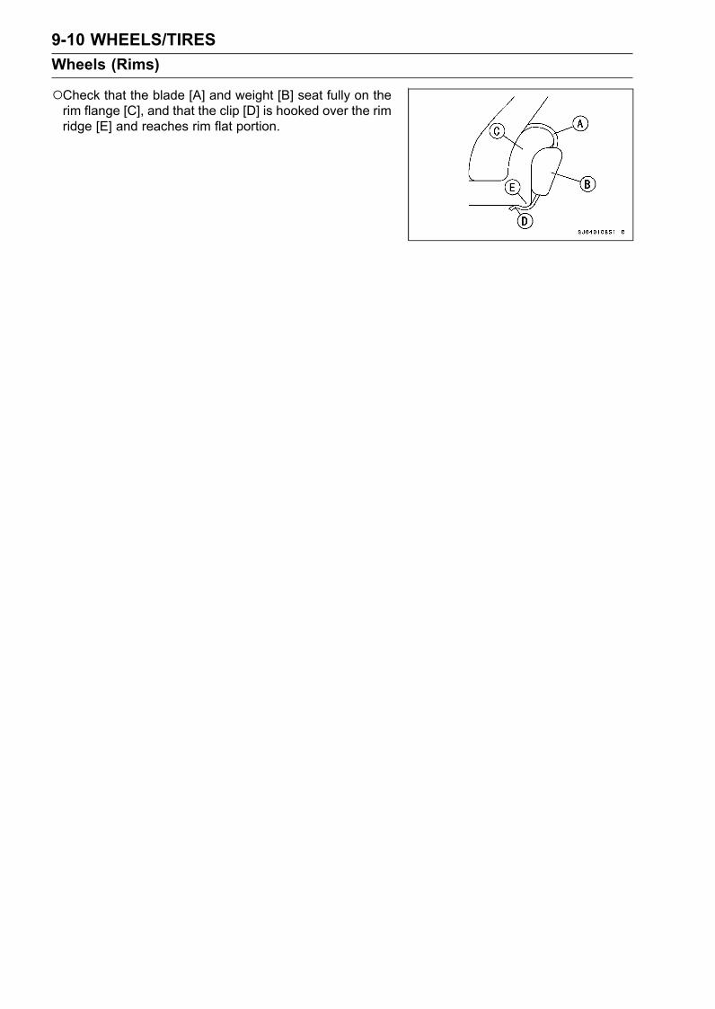
9-10 WHEELS/TIRESWheels (Rims)
Check that the blade [A] and weight [B] seat fully on therim flange [C], and that the clip [D] is hooked over the rimridge [E] and reaches rim flat portion.
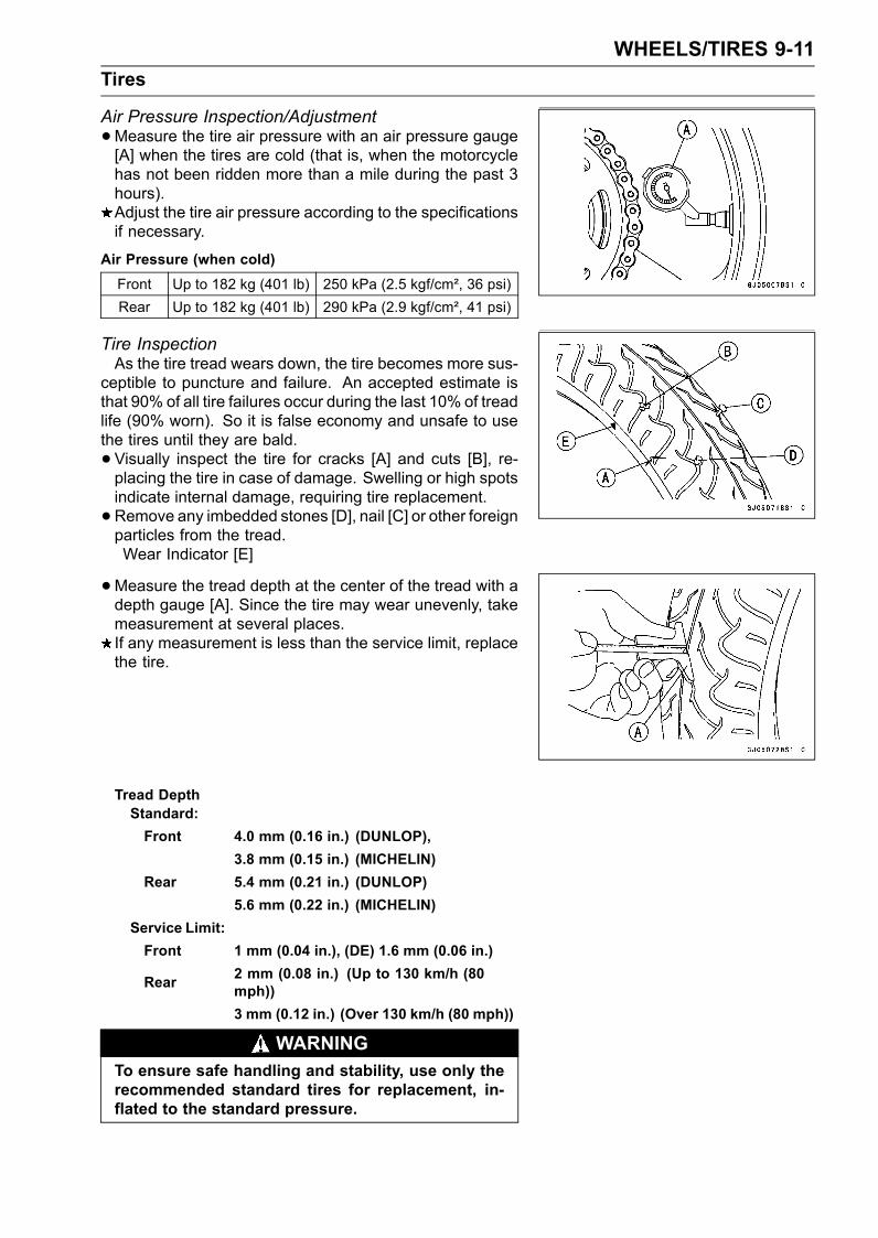
WHEELS/TIRES 9-11Tires
Air Pressure Inspection/Adjustment•Measure the tire air pressure with an air pressure gauge[A] when the tires are cold (that is, when the motorcyclehas not been ridden more than a mile during the past 3hours).Adjust the tire air pressure according to the specificationsif necessary.
Air Pressure (when cold)Front Up to 182 kg (401 lb) 250 kPa (2.5 kgf/cm², 36 psi)Rear Up to 182 kg (401 lb) 290 kPa (2.9 kgf/cm², 41 psi)
Tire InspectionAs the tire tread wears down, the tire becomes more sus-
ceptible to puncture and failure. An accepted estimate isthat 90% of all tire failures occur during the last 10% of treadlife (90% worn). So it is false economy and unsafe to usethe tires until they are bald.• Visually inspect the tire for cracks [A] and cuts [B], re-placing the tire in case of damage. Swelling or high spotsindicate internal damage, requiring tire replacement.•Remove any imbedded stones [D], nail [C] or other foreignparticles from the tread.Wear Indicator [E]
•Measure the tread depth at the center of the tread with adepth gauge [A]. Since the tire may wear unevenly, takemeasurement at several places.If any measurement is less than the service limit, replacethe tire.
Tread DepthStandard:Front 4.0 mm (0.16 in.) (DUNLOP),
3.8 mm (0.15 in.) (MICHELIN)Rear 5.4 mm (0.21 in.) (DUNLOP)
5.6 mm (0.22 in.) (MICHELIN)Service Limit:Front 1 mm (0.04 in.), (DE) 1.6 mm (0.06 in.)
Rear 2 mm (0.08 in.) (Up to 130 km/h (80mph))3 mm (0.12 in.) (Over 130 km/h (80 mph))
WARNINGTo ensure safe handling and stability, use only therecommended standard tires for replacement, in-flated to the standard pressure.
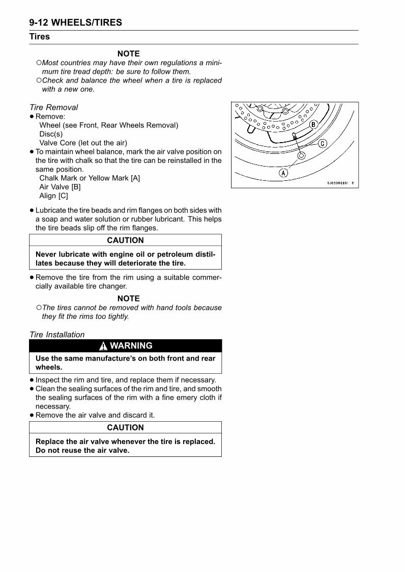
9-12 WHEELS/TIRESTires
NOTEMost countries may have their own regulations a mini-mum tire tread depth: be sure to follow them.Check and balance the wheel when a tire is replacedwith a new one.
Tire Removal•Remove:Wheel (see Front, Rear Wheels Removal)Disc(s)Valve Core (let out the air)• To maintain wheel balance, mark the air valve position onthe tire with chalk so that the tire can be reinstalled in thesame position.Chalk Mark or Yellow Mark [A]Air Valve [B]Align [C]
• Lubricate the tire beads and rim flanges on both sides witha soap and water solution or rubber lubricant. This helpsthe tire beads slip off the rim flanges.
CAUTIONNever lubricate with engine oil or petroleum distil-lates because they will deteriorate the tire.
•Remove the tire from the rim using a suitable commer-cially available tire changer.
NOTEThe tires cannot be removed with hand tools becausethey fit the rims too tightly.
Tire InstallationWARNING
Use the same manufacture’s on both front and rearwheels.
• Inspect the rim and tire, and replace them if necessary.•Clean the sealing surfaces of the rim and tire, and smooththe sealing surfaces of the rim with a fine emery cloth ifnecessary.•Remove the air valve and discard it.
CAUTIONReplace the air valve whenever the tire is replaced.Do not reuse the air valve.
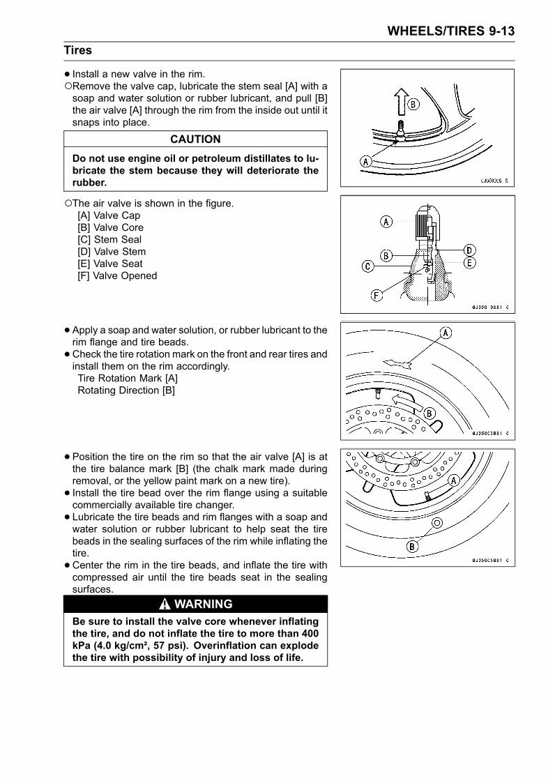
WHEELS/TIRES 9-13Tires
• Install a new valve in the rim.Remove the valve cap, lubricate the stem seal [A] with asoap and water solution or rubber lubricant, and pull [B]the air valve [A] through the rim from the inside out until itsnaps into place.
CAUTIONDo not use engine oil or petroleum distillates to lu-bricate the stem because they will deteriorate therubber.
The air valve is shown in the figure.[A] Valve Cap[B] Valve Core[C] Stem Seal[D] Valve Stem[E] Valve Seat[F] Valve Opened
•Apply a soap and water solution, or rubber lubricant to therim flange and tire beads.•Check the tire rotation mark on the front and rear tires andinstall them on the rim accordingly.Tire Rotation Mark [A]Rotating Direction [B]
• Position the tire on the rim so that the air valve [A] is atthe tire balance mark [B] (the chalk mark made duringremoval, or the yellow paint mark on a new tire).• Install the tire bead over the rim flange using a suitablecommercially available tire changer.• Lubricate the tire beads and rim flanges with a soap andwater solution or rubber lubricant to help seat the tirebeads in the sealing surfaces of the rim while inflating thetire.•Center the rim in the tire beads, and inflate the tire withcompressed air until the tire beads seat in the sealingsurfaces.
WARNINGBe sure to install the valve core whenever inflatingthe tire, and do not inflate the tire to more than 400kPa (4.0 kg/cm², 57 psi). Overinflation can explodethe tire with possibility of injury and loss of life.
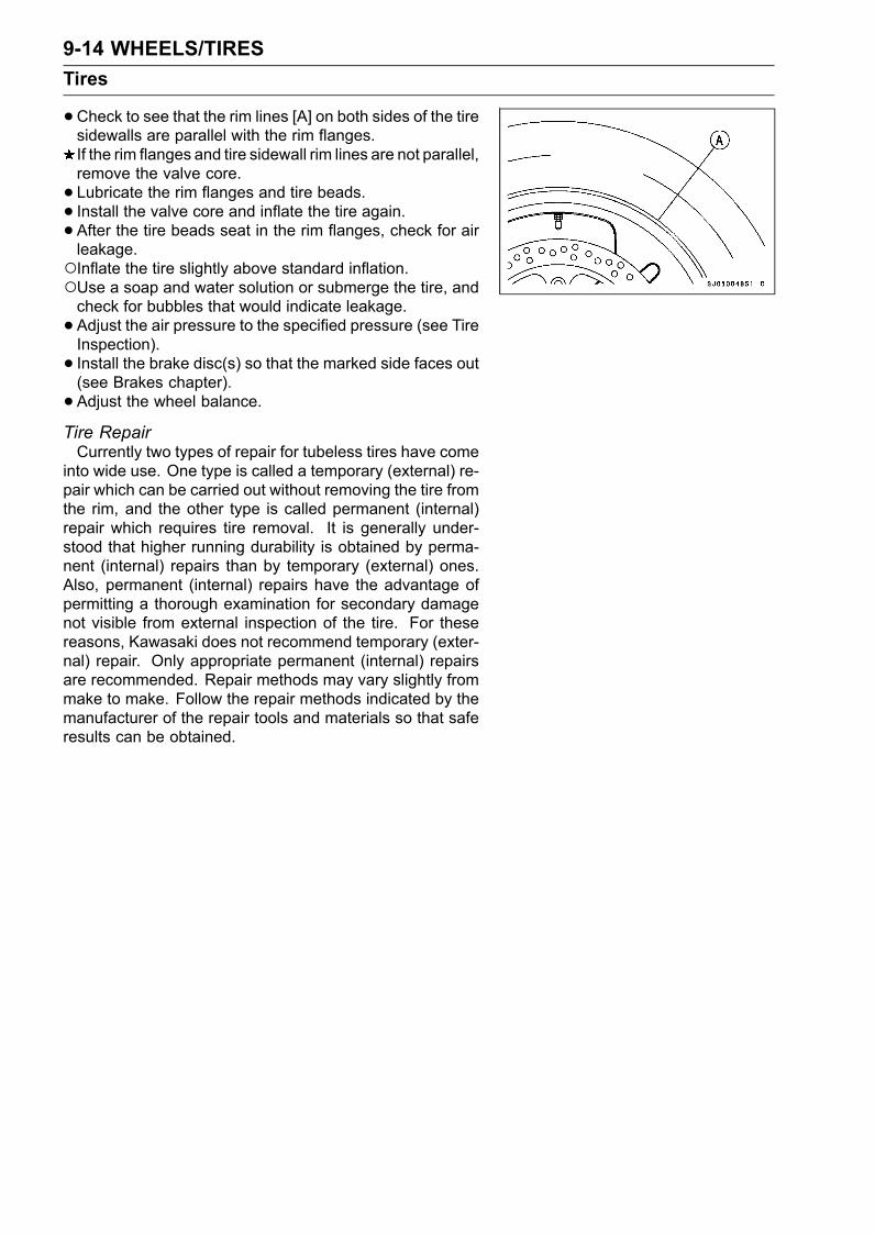
9-14 WHEELS/TIRESTires
•Check to see that the rim lines [A] on both sides of the tiresidewalls are parallel with the rim flanges.If the rim flanges and tire sidewall rim lines are not parallel,remove the valve core.• Lubricate the rim flanges and tire beads.• Install the valve core and inflate the tire again.• After the tire beads seat in the rim flanges, check for airleakage.Inflate the tire slightly above standard inflation.Use a soap and water solution or submerge the tire, andcheck for bubbles that would indicate leakage.• Adjust the air pressure to the specified pressure (see TireInspection).• Install the brake disc(s) so that the marked side faces out(see Brakes chapter).• Adjust the wheel balance.Tire RepairCurrently two types of repair for tubeless tires have come
into wide use. One type is called a temporary (external) re-pair which can be carried out without removing the tire fromthe rim, and the other type is called permanent (internal)repair which requires tire removal. It is generally under-stood that higher running durability is obtained by perma-nent (internal) repairs than by temporary (external) ones.Also, permanent (internal) repairs have the advantage ofpermitting a thorough examination for secondary damagenot visible from external inspection of the tire. For thesereasons, Kawasaki does not recommend temporary (exter-nal) repair. Only appropriate permanent (internal) repairsare recommended. Repair methods may vary slightly frommake to make. Follow the repair methods indicated by themanufacturer of the repair tools and materials so that saferesults can be obtained.
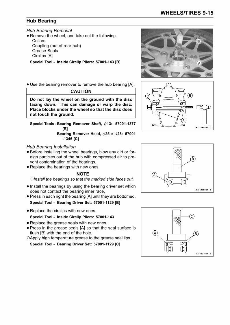
WHEELS/TIRES 9-15Hub Bearing
Hub Bearing Removal•Remove the wheel, and take out the following.CollarsCoupling (out of rear hub)Grease SealsCirclips [A]Special Tool - Inside Circlip Pliers: 57001-143 [B]
•Use the bearing remover to remove the hub bearing [A].CAUTION
Do not lay the wheel on the ground with the discfacing down. This can damage or warp the disc.Place blocks under the wheel so that the disc doesnot touch the ground.
Special Tools - Bearing Remover Shaft, 13: 57001-1377[B]
Bearing Remover Head, 25 × 28: 57001-1346 [C]
Hub Bearing Installation•Before installing the wheel bearings, blow any dirt or for-eign particles out of the hub with compressed air to pre-vent contamination of the bearings.•Replace the bearings with new ones.
NOTEInstall the bearings so that the marked side faces out.• Install the bearings by using the bearing driver set whichdoes not contact the bearing inner race.• Press in each right the bearing [A] until they are bottomed.Special Tool - Bearing Driver Set: 57001-1129 [B]
•Replace the circlips with new ones.Special Tool - Inside Circlip Pliers: 57001-143
•Replace the grease seals with new ones.• Press in the grease seals [A] so that the seal surface isflush [B] with the end of the hole.Apply high temperature grease to the grease seal lips.Special Tool - Bearing Driver Set: 57001-1129 [C]
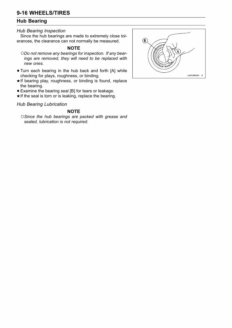
9-16 WHEELS/TIRESHub Bearing
Hub Bearing InspectionSince the hub bearings are made to extremely close tol-
erances, the clearance can not normally be measured.
NOTEDo not remove any bearings for inspection. If any bear-ings are removed, they will need to be replaced withnew ones.
•Turn each bearing in the hub back and forth [A] whilechecking for plays, roughness, or binding.If bearing play, roughness, or binding is found, replacethe bearing.• Examine the bearing seal [B] for tears or leakage.If the seal is torn or is leaking, replace the bearing.
Hub Bearing LubricationNOTE
Since the hub bearings are packed with grease andsealed, lubrication is not required.
FINAL DRIVE 10-1
10
Final DriveTable of Contents
Exploded View ....................................................................................................................... 10-2Specifications ........................................................................................................................ 10-3Drive Chain............................................................................................................................. 10-4
Drive Chain Slack Inspection ............................................................................................ 10-4Drive Chain Slack Adjustment .......................................................................................... 10-4Wheel Alignment Inspection/Adjustment .......................................................................... 10-4Drive Chain Wear Inspection ............................................................................................ 10-5Drive Chain Lubrication..................................................................................................... 10-5Drive Chain Removal ........................................................................................................ 10-6Drive Chain Installation ..................................................................................................... 10-6Drive Chain Replacement (ZX600-J4 ∼ (US), ZX600J6F ∼ (CA))..................................... 10-7
Sprocket, Coupling ................................................................................................................. 10-10Engine Sprocket Removal ................................................................................................ 10-10Engine Sprocket Installation ............................................................................................. 10-10Rear Sprocket Removal.................................................................................................... 10-11Rear Sprocket Installation................................................................................................. 10-11Coupling Installation.......................................................................................................... 10-11Coupling Bearing Removal ............................................................................................... 10-11Coupling Bearing Installation ............................................................................................ 10-12Coupling Bearing Inspection ............................................................................................. 10-12Coupling Bearing Lubrication............................................................................................ 10-12Coupling Damper Inspection............................................................................................. 10-12Sprocket Wear Inspection................................................................................................. 10-13Rear Sprocket Warp Inspection ........................................................................................ 10-13
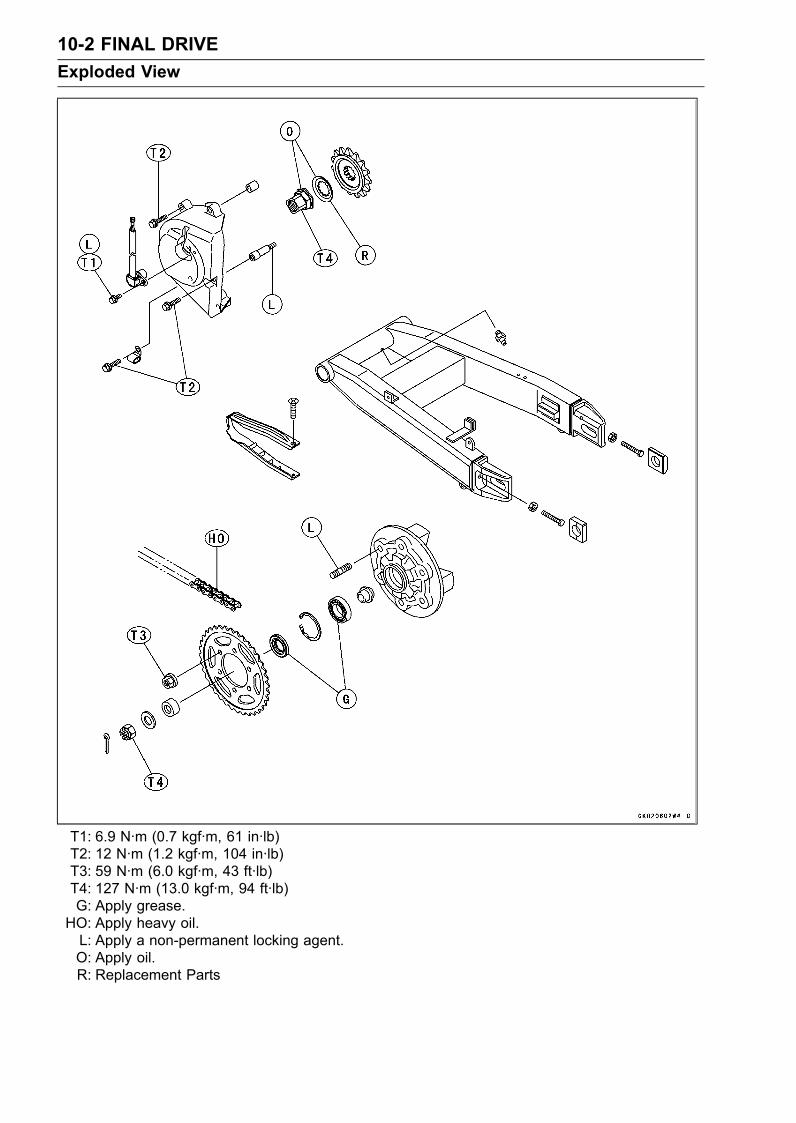
10-2 FINAL DRIVEExploded View
T1: 6.9 N·m (0.7 kgf·m, 61 in·lb)T2: 12 N·m (1.2 kgf·m, 104 in·lb)T3: 59 N·m (6.0 kgf·m, 43 ft·lb)T4: 127 N·m (13.0 kgf·m, 94 ft·lb)G: Apply grease.HO: Apply heavy oil.L: Apply a non-permanent locking agent.O: Apply oil.R: Replacement Parts
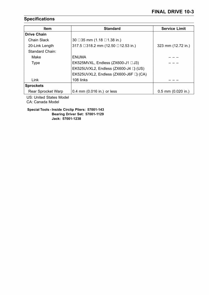
FINAL DRIVE 10-3Specifications
Item Standard Service LimitDrive ChainChain Slack 30 ∼ 35 mm (1.18 ∼ 1.38 in.)20-Link Length 317.5 ∼ 318.2 mm (12.50 ∼ 12.53 in.) 323 mm (12.72 in.)Standard Chain:Make ENUMA – – –Type EK525MVXL, Endless (ZX600-J1 ∼ J3) – – –
EK525UVXL2, Endless (ZX600-J4 ∼ ) (US)EK525UVXL2, Endless (ZX600-J6F ∼ ) (CA)
Link 108 links – – –SprocketsRear Sprocket Warp 0.4 mm (0.016 in.) or less 0.5 mm (0.020 in.)US: United States ModelCA: Canada Model
Special Tools - Inside Circlip Pliers: 57001-143Bearing Driver Set: 57001-1129Jack: 57001-1238
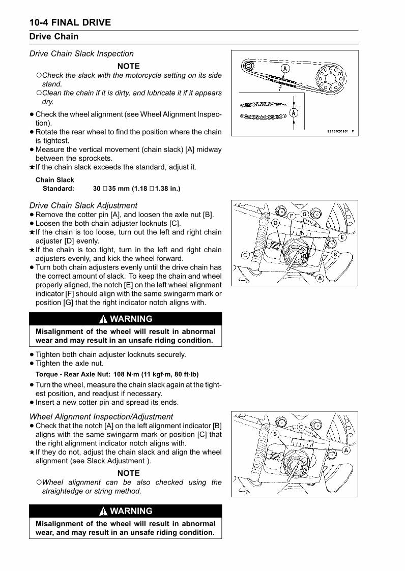
10-4 FINAL DRIVEDrive Chain
Drive Chain Slack InspectionNOTE
Check the slack with the motorcycle setting on its sidestand.Clean the chain if it is dirty, and lubricate it if it appearsdry.
•Check the wheel alignment (seeWheel Alignment Inspec-tion).• Rotate the rear wheel to find the position where the chainis tightest.•Measure the vertical movement (chain slack) [A] midwaybetween the sprockets.If the chain slack exceeds the standard, adjust it.
Chain SlackStandard: 30 ∼ 35 mm (1.18 ∼ 1.38 in.)
Drive Chain Slack Adjustment•Remove the cotter pin [A], and loosen the axle nut [B].• Loosen the both chain adjuster locknuts [C].If the chain is too loose, turn out the left and right chainadjuster [D] evenly.If the chain is too tight, turn in the left and right chainadjusters evenly, and kick the wheel forward.• Turn both chain adjusters evenly until the drive chain hasthe correct amount of slack. To keep the chain and wheelproperly aligned, the notch [E] on the left wheel alignmentindicator [F] should align with the same swingarm mark orposition [G] that the right indicator notch aligns with.
WARNINGMisalignment of the wheel will result in abnormalwear and may result in an unsafe riding condition.
•Tighten both chain adjuster locknuts securely.• Tighten the axle nut.Torque - Rear Axle Nut: 108 N·m (11 kgf·m, 80 ft·lb)
•Turn the wheel, measure the chain slack again at the tight-est position, and readjust if necessary.• Insert a new cotter pin and spread its ends.Wheel Alignment Inspection/Adjustment•Check that the notch [A] on the left alignment indicator [B]aligns with the same swingarm mark or position [C] thatthe right alignment indicator notch aligns with.If they do not, adjust the chain slack and align the wheelalignment (see Slack Adjustment ).
NOTEWheel alignment can be also checked using thestraightedge or string method.
WARNINGMisalignment of the wheel will result in abnormalwear, and may result in an unsafe riding condition.
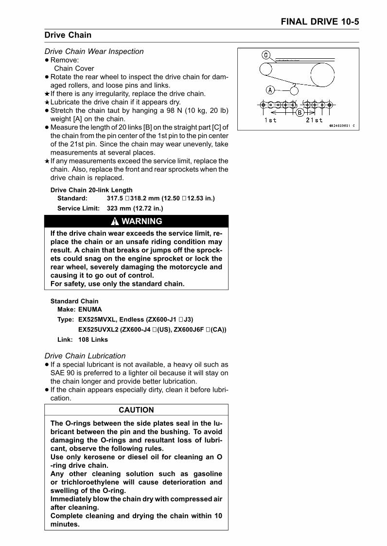
FINAL DRIVE 10-5Drive Chain
Drive Chain Wear Inspection•Remove:Chain Cover•Rotate the rear wheel to inspect the drive chain for dam-aged rollers, and loose pins and links.If there is any irregularity, replace the drive chain.Lubricate the drive chain if it appears dry.• Stretch the chain taut by hanging a 98 N (10 kg, 20 lb)weight [A] on the chain.•Measure the length of 20 links [B] on the straight part [C] ofthe chain from the pin center of the 1st pin to the pin centerof the 21st pin. Since the chain may wear unevenly, takemeasurements at several places.If any measurements exceed the service limit, replace thechain. Also, replace the front and rear sprockets when thedrive chain is replaced.
Drive Chain 20-link LengthStandard: 317.5 ∼ 318.2 mm (12.50 ∼ 12.53 in.)Service Limit: 323 mm (12.72 in.)
WARNINGIf the drive chain wear exceeds the service limit, re-place the chain or an unsafe riding condition mayresult. A chain that breaks or jumps off the sprock-ets could snag on the engine sprocket or lock therear wheel, severely damaging the motorcycle andcausing it to go out of control.For safety, use only the standard chain.
Standard ChainMake: ENUMAType: EX525MVXL, Endless (ZX600-J1 ∼ J3)
EX525UVXL2 (ZX600-J4 ∼ (US), ZX600J6F ∼ (CA))Link: 108 Links
Drive Chain Lubrication• If a special lubricant is not available, a heavy oil such asSAE 90 is preferred to a lighter oil because it will stay onthe chain longer and provide better lubrication.• If the chain appears especially dirty, clean it before lubri-cation.
CAUTIONThe O-rings between the side plates seal in the lu-bricant between the pin and the bushing. To avoiddamaging the O-rings and resultant loss of lubri-cant, observe the following rules.Use only kerosene or diesel oil for cleaning an O-ring drive chain.Any other cleaning solution such as gasolineor trichloroethylene will cause deterioration andswelling of the O-ring.Immediately blow the chain drywith compressed airafter cleaning.Complete cleaning and drying the chain within 10minutes.
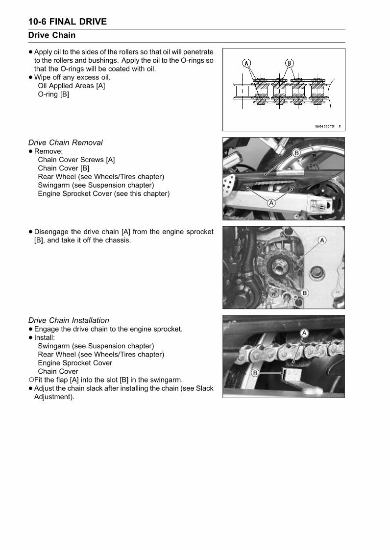
10-6 FINAL DRIVEDrive Chain
•Apply oil to the sides of the rollers so that oil will penetrateto the rollers and bushings. Apply the oil to the O-rings sothat the O-rings will be coated with oil.•Wipe off any excess oil.Oil Applied Areas [A]O-ring [B]
Drive Chain Removal•Remove:Chain Cover Screws [A]Chain Cover [B]Rear Wheel (see Wheels/Tires chapter)Swingarm (see Suspension chapter)Engine Sprocket Cover (see this chapter)
•Disengage the drive chain [A] from the engine sprocket[B], and take it off the chassis.
Drive Chain Installation•Engage the drive chain to the engine sprocket.• Install:Swingarm (see Suspension chapter)Rear Wheel (see Wheels/Tires chapter)Engine Sprocket CoverChain Cover
Fit the flap [A] into the slot [B] in the swingarm.• Adjust the chain slack after installing the chain (see SlackAdjustment).
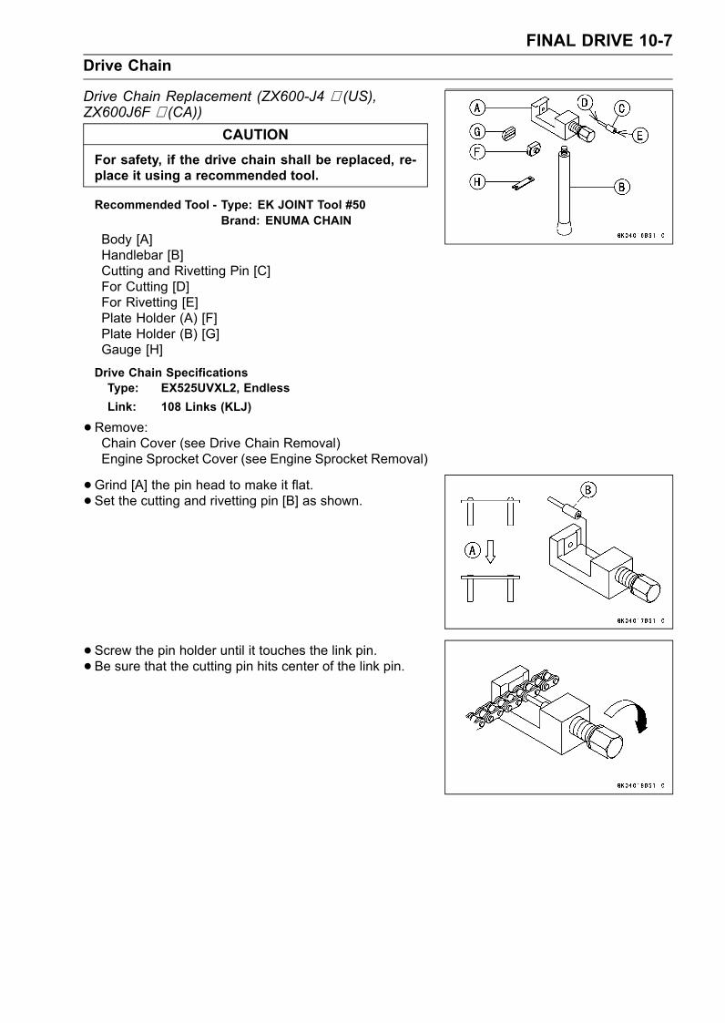
FINAL DRIVE 10-7Drive Chain
Drive Chain Replacement (ZX600-J4 ∼ (US),ZX600J6F ∼ (CA))
CAUTIONFor safety, if the drive chain shall be replaced, re-place it using a recommended tool.
Recommended Tool - Type: EK JOINT Tool #50Brand: ENUMA CHAIN
Body [A]Handlebar [B]Cutting and Rivetting Pin [C]For Cutting [D]For Rivetting [E]Plate Holder (A) [F]Plate Holder (B) [G]Gauge [H]
Drive Chain SpecificationsType: EX525UVXL2, EndlessLink: 108 Links (KLJ)
•Remove:Chain Cover (see Drive Chain Removal)Engine Sprocket Cover (see Engine Sprocket Removal)
•Grind [A] the pin head to make it flat.• Set the cutting and rivetting pin [B] as shown.
• Screw the pin holder until it touches the link pin.• Be sure that the cutting pin hits center of the link pin.
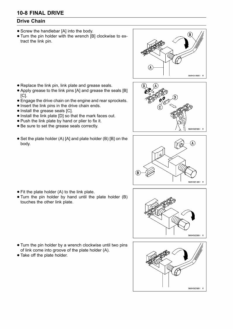
10-8 FINAL DRIVEDrive Chain
•Screw the handlebar [A] into the body.• Turn the pin holder with the wrench [B] clockwise to ex-tract the link pin.
•Replace the link pin, link plate and grease seals.• Apply grease to the link pins [A] and grease the seals [B][C].• Engage the drive chain on the engine and rear sprockets.• Insert the link pins in the drive chain ends.• Install the grease seals [C].• Install the link plate [D] so that the mark faces out.• Push the link plate by hand or plier to fix it.• Be sure to set the grease seals correctly.
• Set the plate holder (A) [A] and plate holder (B) [B] on thebody.
• Fit the plate holder (A) to the link plate.• Turn the pin holder by hand until the plate holder (B)touches the other link plate.
• Turn the pin holder by a wrench clockwise until two pinsof link come into groove of the plate holder (A).• Take off the plate holder.
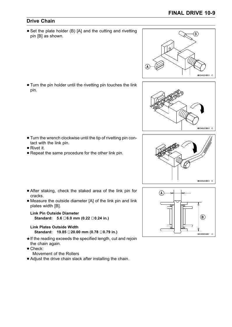
FINAL DRIVE 10-9Drive Chain
•Set the plate holder (B) [A] and the cutting and rivettingpin [B] as shown.
• Turn the pin holder until the rivetting pin touches the linkpin.
• Turn the wrench clockwise until the tip of rivetting pin con-tact with the link pin.•Rivet it.• Repeat the same procedure for the other link pin.
• After staking, check the staked area of the link pin forcracks.•Measure the outside diameter [A] of the link pin and linkplates width [B].
Link Pin Outside DiameterStandard: 5.6 ∼ 6.0 mm (0.22 ∼ 0.24 in.)
Link Plates Outside WidthStandard: 19.85 ∼ 20.00 mm (0.78 ∼ 0.79 in.)
If the reading exceeds the specified length, cut and rejointhe chain again.•Check:Movement of the Rollers• Adjust the drive chain slack after installing the chain.
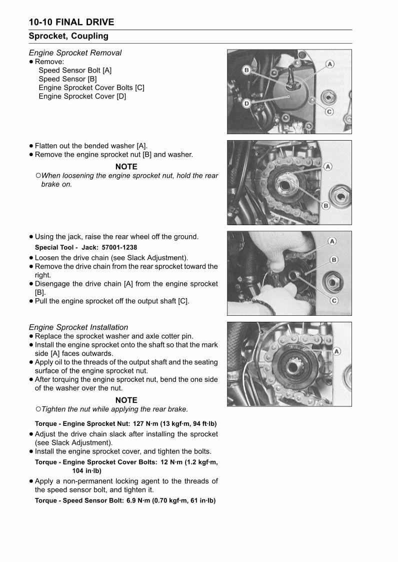
10-10 FINAL DRIVESprocket, Coupling
Engine Sprocket Removal•Remove:Speed Sensor Bolt [A]Speed Sensor [B]Engine Sprocket Cover Bolts [C]Engine Sprocket Cover [D]
• Flatten out the bended washer [A].• Remove the engine sprocket nut [B] and washer.NOTE
When loosening the engine sprocket nut, hold the rearbrake on.
•Using the jack, raise the rear wheel off the ground.Special Tool - Jack: 57001-1238
• Loosen the drive chain (see Slack Adjustment).• Remove the drive chain from the rear sprocket toward theright.• Disengage the drive chain [A] from the engine sprocket[B].• Pull the engine sprocket off the output shaft [C].
Engine Sprocket Installation•Replace the sprocket washer and axle cotter pin.• Install the engine sprocket onto the shaft so that the markside [A] faces outwards.• Apply oil to the threads of the output shaft and the seatingsurface of the engine sprocket nut.• After torquing the engine sprocket nut, bend the one sideof the washer over the nut.
NOTETighten the nut while applying the rear brake.Torque - Engine Sprocket Nut: 127 N·m (13 kgf·m, 94 ft·lb)
•Adjust the drive chain slack after installing the sprocket(see Slack Adjustment).• Install the engine sprocket cover, and tighten the bolts.Torque - Engine Sprocket Cover Bolts: 12 N·m (1.2 kgf·m,
104 in·lb)
•Apply a non-permanent locking agent to the threads ofthe speed sensor bolt, and tighten it.Torque - Speed Sensor Bolt: 6.9 N·m (0.70 kgf·m, 61 in·lb)
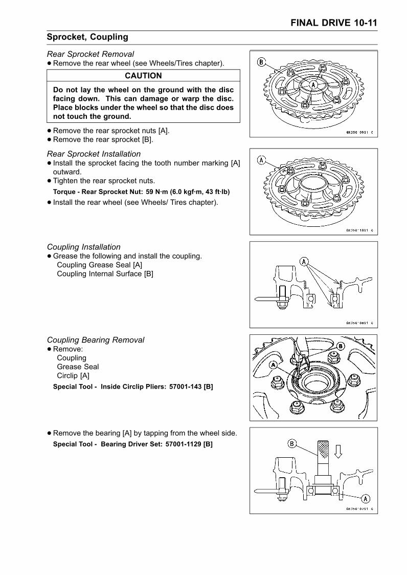
FINAL DRIVE 10-11Sprocket, Coupling
Rear Sprocket Removal•Remove the rear wheel (see Wheels/Tires chapter).
CAUTIONDo not lay the wheel on the ground with the discfacing down. This can damage or warp the disc.Place blocks under the wheel so that the disc doesnot touch the ground.
•Remove the rear sprocket nuts [A].• Remove the rear sprocket [B].Rear Sprocket Installation• Install the sprocket facing the tooth number marking [A]outward.• Tighten the rear sprocket nuts.Torque - Rear Sprocket Nut: 59 N·m (6.0 kgf·m, 43 ft·lb)
• Install the rear wheel (see Wheels/ Tires chapter).
Coupling Installation•Grease the following and install the coupling.Coupling Grease Seal [A]Coupling Internal Surface [B]
Coupling Bearing Removal•Remove:CouplingGrease SealCirclip [A]Special Tool - Inside Circlip Pliers: 57001-143 [B]
•Remove the bearing [A] by tapping from the wheel side.Special Tool - Bearing Driver Set: 57001-1129 [B]
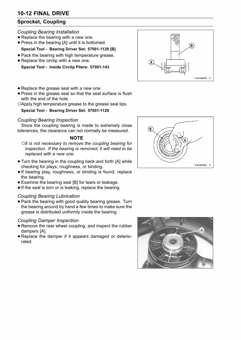
10-12 FINAL DRIVESprocket, Coupling
Coupling Bearing Installation•Replace the bearing with a new one.• Press in the bearing [A] until it is bottomed.Special Tool - Bearing Driver Set: 57001-1129 [B]
•Pack the bearing with high temperature grease.•Replace the circlip with a new one.Special Tool - Inside Circlip Pliers: 57001-143
•Replace the grease seal with a new one.• Press in the grease seal so that the seal surface is flushwith the end of the hole.Apply high temperature grease to the grease seal lips.Special Tool - Bearing Driver Set: 57001-1129
Coupling Bearing InspectionSince the coupling bearing is made to extremely close
tolerances, the clearance can not normally be measured.
NOTEIt is not necessary to remove the coupling bearing forinspection. If the bearing is removed, it will need to bereplaced with a new one.
•Turn the bearing in the coupling back and forth [A] whilechecking for plays, roughness, or binding.If bearing play, roughness, or binding is found, replacethe bearing.• Examine the bearing seal [B] for tears or leakage.If the seal is torn or is leaking, replace the bearing.
Coupling Bearing Lubrication•Pack the bearing with good quality bearing grease. Turnthe bearing around by hand a few times to make sure thegrease is distributed uniformly inside the bearing.
Coupling Damper Inspection•Remove the rear wheel coupling, and inspect the rubberdampers [A].• Replace the damper if it appears damaged or deterio-rated.
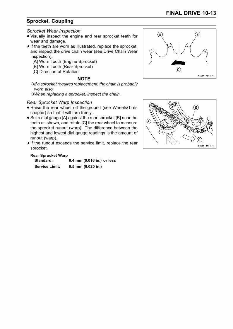
FINAL DRIVE 10-13Sprocket, Coupling
Sprocket Wear Inspection•Visually inspect the engine and rear sprocket teeth forwear and damage.If the teeth are worn as illustrated, replace the sprocket,and inspect the drive chain wear (see Drive Chain WearInspection).[A] Worn Tooth (Engine Sprocket)[B] Worn Tooth (Rear Sprocket)[C] Direction of Rotation
NOTEIf a sprocket requires replacement, the chain is probablyworn also.When replacing a sprocket, inspect the chain.
Rear Sprocket Warp Inspection•Raise the rear wheel off the ground (see Wheels/Tireschapter) so that it will turn freely.• Set a dial gauge [A] against the rear sprocket [B] near theteeth as shown, and rotate [C] the rear wheel to measurethe sprocket runout (warp). The difference between thehighest and lowest dial gauge readings is the amount ofrunout (warp).If the runout exceeds the service limit, replace the rearsprocket.
Rear Sprocket WarpStandard: 0.4 mm (0.016 in.) or lessService Limit: 0.5 mm (0.020 in.)

BRAKES 11-1
11
BrakesTable of Contents
Exploded View .................................. 11-2Specifications ................................... 11-4Brake Pedal ....................................... 11-5
Brake Lever Position Adjustment. 11-5Brake Pedal Position Inspection . 11-5Brake Pedal Position Adjustment 11-5
Calipers ............................................. 11-6Front Caliper Removal ................. 11-6Rear Caliper Removal.................. 11-6Caliper Installation ....................... 11-6Front Caliper Disassembly........... 11-7Front Caliper Assembly................ 11-8Rear Caliper Disassembly ........... 11-8Rear Caliper Assembly ................ 11-9Caliper Fluid Seal DamageInspection.................................. 11-10
Caliper Dust Seal/Rubber BootDamage Inspection ................... 11-10
Caliper Piston and CylinderDamage Insepction ................... 11-10
Caliper Holder Shaft WearInspection.................................. 11-10
Brake Pads........................................ 11-11Front Brake Pad Removal............ 11-11Front Brake Pad Installation......... 11-11Rear Brake Pad Removal ........... 11-11
Rear Brake Pad Installation ......... 11-12Brake Pad Wear Inspection ......... 11-12
Master Cylinder ................................. 11-13Front Master Cylinder Removal ... 11-13Front Master Cylinder Installation 11-13Rear Master Cylinder Removal.... 11-13Rear Master Cylinder Installation. 11-14Front Master CylinderDisassembly.............................. 11-14
Rear Master CylinderDisassembly.............................. 11-14
Master Cylinder Assembly ........... 11-15Master Cylinder Inspection (VisualInspection)................................. 11-15
Brake Disc ......................................... 11-17Brake Disc Removal .................... 11-17Brake Disc Installation ................. 11-17Brake Disc Wear Inspection......... 11-17Brake Disc Warp Inspection......... 11-17
Brake Fluid ........................................ 11-18Level Inspection ........................... 11-18Brake Fluid Change ..................... 11-18Bleeding the Brake Line............... 11-19
Brake Hose........................................ 11-22Brake Hose Removal/Installation. 11-22Brake Hose Inspection................. 11-22
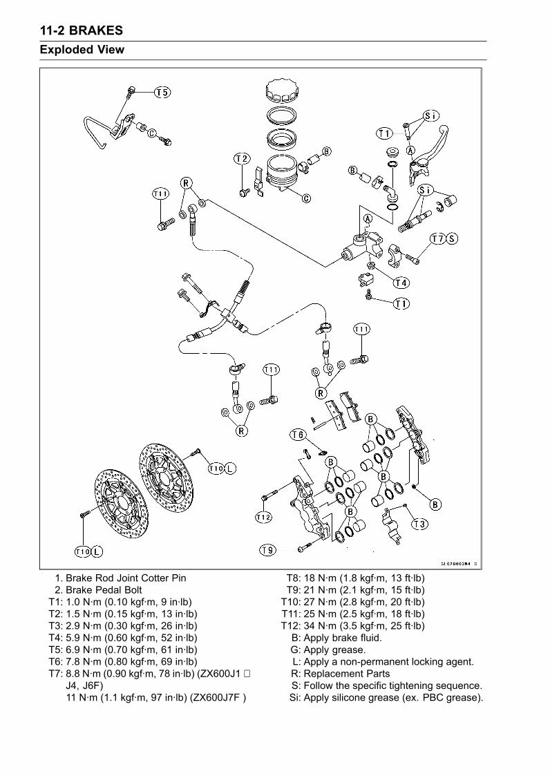
11-2 BRAKESExploded View
1. Brake Rod Joint Cotter Pin2. Brake Pedal BoltT1: 1.0 N·m (0.10 kgf·m, 9 in·lb)T2: 1.5 N·m (0.15 kgf·m, 13 in·lb)T3: 2.9 N·m (0.30 kgf·m, 26 in·lb)T4: 5.9 N·m (0.60 kgf·m, 52 in·lb)T5: 6.9 N·m (0.70 kgf·m, 61 in·lb)T6: 7.8 N·m (0.80 kgf·m, 69 in·lb)T7: 8.8 N·m (0.90 kgf·m, 78 in·lb) (ZX600J1 ∼
J4, J6F)11 N·m (1.1 kgf·m, 97 in·lb) (ZX600J7F )
T8: 18 N·m (1.8 kgf·m, 13 ft·lb)T9: 21 N·m (2.1 kgf·m, 15 ft·lb)T10: 27 N·m (2.8 kgf·m, 20 ft·lb)T11: 25 N·m (2.5 kgf·m, 18 ft·lb)T12: 34 N·m (3.5 kgf·m, 25 ft·lb)B: Apply brake fluid.G: Apply grease.L: Apply a non-permanent locking agent.R: Replacement PartsS: Follow the specific tightening sequence.Si: Apply silicone grease (ex. PBC grease).
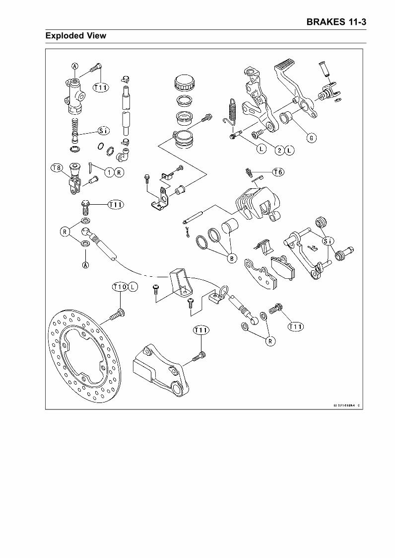
BRAKES 11-3Exploded View
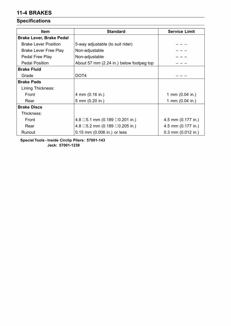
11-4 BRAKESSpecifications
Item Standard Service LimitBrake Lever, Brake PedalBrake Lever Position 5-way adjustable (to suit rider) – – –Brake Lever Free Play Non-adjustable – – –Pedal Free Play Non-adjustable – – –Pedal Position About 57 mm (2.24 in.) below footpeg top – – –
Brake FluidGrade DOT4 – – –
Brake PadsLining Thickness:Front 4 mm (0.16 in.) 1 mm (0.04 in.)Rear 5 mm (0.20 in.) 1 mm (0.04 in.)
Brake DiscsThickness:Front 4.8 ∼ 5.1 mm (0.189 ∼ 0.201 in.) 4.5 mm (0.177 in.)Rear 4.8 ∼ 5.2 mm (0.189 ∼ 0.205 in.) 4.5 mm (0.177 in.)
Runout 0.15 mm (0.006 in.) or less 0.3 mm (0.012 in.)
Special Tools - Inside Circlip Pliers: 57001-143Jack: 57001-1238
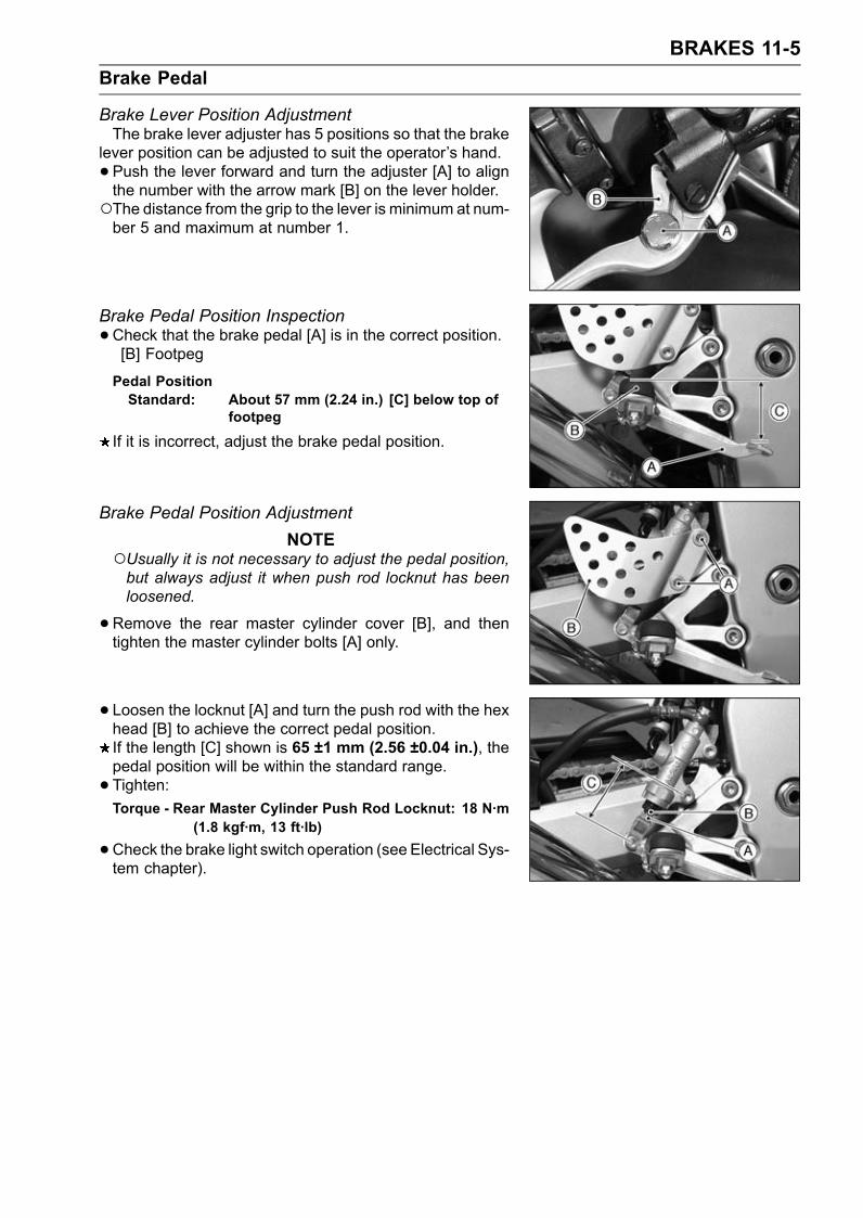
BRAKES 11-5Brake Pedal
Brake Lever Position AdjustmentThe brake lever adjuster has 5 positions so that the brake
lever position can be adjusted to suit the operator’s hand.• Push the lever forward and turn the adjuster [A] to alignthe number with the arrow mark [B] on the lever holder.The distance from the grip to the lever is minimum at num-ber 5 and maximum at number 1.
Brake Pedal Position Inspection•Check that the brake pedal [A] is in the correct position.[B] Footpeg
Pedal PositionStandard: About 57 mm (2.24 in.) [C] below top of
footpeg
If it is incorrect, adjust the brake pedal position.
Brake Pedal Position AdjustmentNOTE
Usually it is not necessary to adjust the pedal position,but always adjust it when push rod locknut has beenloosened.
•Remove the rear master cylinder cover [B], and thentighten the master cylinder bolts [A] only.
• Loosen the locknut [A] and turn the push rod with the hexhead [B] to achieve the correct pedal position.If the length [C] shown is 65 ±1 mm (2.56 ±0.04 in.), thepedal position will be within the standard range.• Tighten:Torque - Rear Master Cylinder Push Rod Locknut: 18 N·m
(1.8 kgf·m, 13 ft·lb)
•Check the brake light switch operation (see Electrical Sys-tem chapter).
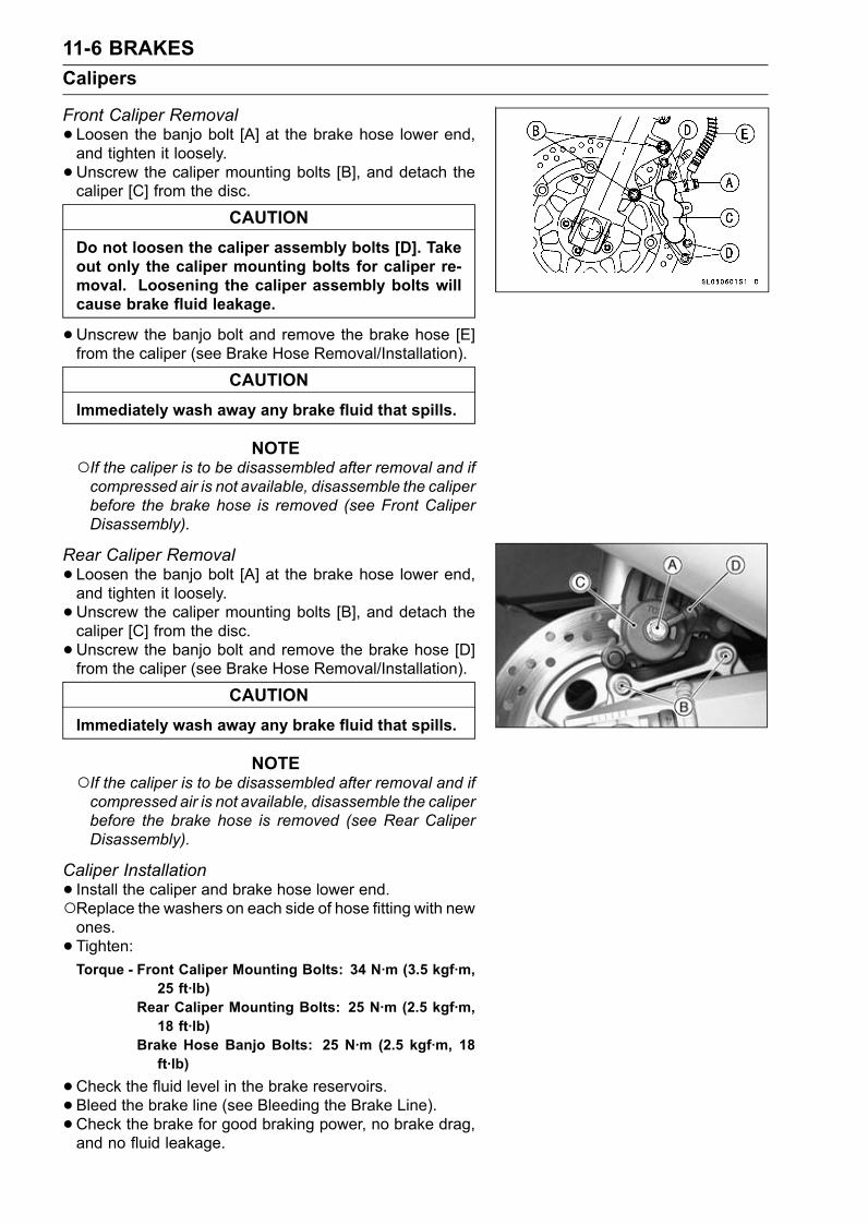
11-6 BRAKESCalipers
Front Caliper Removal• Loosen the banjo bolt [A] at the brake hose lower end,and tighten it loosely.•Unscrew the caliper mounting bolts [B], and detach thecaliper [C] from the disc.
CAUTIONDo not loosen the caliper assembly bolts [D]. Takeout only the caliper mounting bolts for caliper re-moval. Loosening the caliper assembly bolts willcause brake fluid leakage.
•Unscrew the banjo bolt and remove the brake hose [E]from the caliper (see Brake Hose Removal/Installation).
CAUTIONImmediately wash away any brake fluid that spills.
NOTEIf the caliper is to be disassembled after removal and ifcompressed air is not available, disassemble the caliperbefore the brake hose is removed (see Front CaliperDisassembly).
Rear Caliper Removal• Loosen the banjo bolt [A] at the brake hose lower end,and tighten it loosely.•Unscrew the caliper mounting bolts [B], and detach thecaliper [C] from the disc.•Unscrew the banjo bolt and remove the brake hose [D]from the caliper (see Brake Hose Removal/Installation).
CAUTIONImmediately wash away any brake fluid that spills.
NOTEIf the caliper is to be disassembled after removal and ifcompressed air is not available, disassemble the caliperbefore the brake hose is removed (see Rear CaliperDisassembly).
Caliper Installation• Install the caliper and brake hose lower end.Replace the washers on each side of hose fitting with newones.• Tighten:Torque - Front Caliper Mounting Bolts: 34 N·m (3.5 kgf·m,
25 ft·lb)Rear Caliper Mounting Bolts: 25 N·m (2.5 kgf·m,18 ft·lb)
Brake Hose Banjo Bolts: 25 N·m (2.5 kgf·m, 18ft·lb)
•Check the fluid level in the brake reservoirs.• Bleed the brake line (see Bleeding the Brake Line).• Check the brake for good braking power, no brake drag,and no fluid leakage.
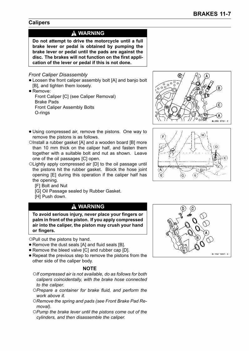
BRAKES 11-7Calipers
WARNINGDo not attempt to drive the motorcycle until a fullbrake lever or pedal is obtained by pumping thebrake lever or pedal until the pads are against thedisc. The brakes will not function on the first appli-cation of the lever or pedal if this is not done.
Front Caliper Disassembly• Loosen the front caliper assembly bolt [A] and banjo bolt[B], and tighten them loosely.•Remove:Front Caliper [C] (see Caliper Removal)Brake PadsFront Caliper Assembly BoltsO-rings
•Using compressed air, remove the pistons. One way toremove the pistons is as follows.Install a rubber gasket [A] and a wooden board [B] morethan 10 mm thick on the caliper half, and fasten themtogether with a suitable bolt and nut as shown. Leaveone of the oil passages [C] open.Lightly apply compressed air [D] to the oil passage untilthe pistons hit the rubber gasket. Block the hose jointopening [E] during this operation if the caliper half hasthe opening.[F] Bolt and Nut[G] Oil Passage sealed by Rubber Gasket.[H] Push down.
WARNINGTo avoid serious injury, never place your fingers orpalm in front of the piston. If you apply compressedair into the caliper, the piston may crush your handor fingers.
Pull out the pistons by hand.•Remove the dust seals [A] and fluid seals [B].• Remove the bleed valve [C] and rubber cap [D].• Repeat the previous step to remove the pistons from theother side of the caliper body.
NOTEIf compressed air is not available, do as follows for bothcalipers coincidentally, with the brake hose connectedto the caliper.Prepare a container for brake fluid, and perform thework above it.Remove the spring and pads (see Front Brake Pad Re-moval).Pump the brake lever until the pistons come out of thecylinders, and then disassemble the caliper.
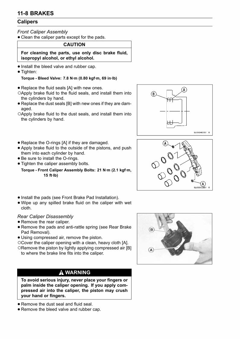
11-8 BRAKESCalipers
Front Caliper Assembly•Clean the caliper parts except for the pads.
CAUTIONFor cleaning the parts, use only disc brake fluid,isopropyl alcohol, or ethyl alcohol.
• Install the bleed valve and rubber cap.• Tighten:Torque - Bleed Valve: 7.8 N·m (0.80 kgf·m, 69 in·lb)
•Replace the fluid seals [A] with new ones.Apply brake fluid to the fluid seals, and install them intothe cylinders by hand.•Replace the dust seals [B] with new ones if they are dam-aged.Apply brake fluid to the dust seals, and install them intothe cylinders by hand.
•Replace the O-rings [A] if they are damaged.• Apply brake fluid to the outside of the pistons, and pushthem into each cylinder by hand.• Be sure to install the O-rings.• Tighten the caliper assembly bolts.Torque - Front Caliper Assembly Bolts: 21 N·m (2.1 kgf·m,
15 ft·lb)
• Install the pads (see Front Brake Pad Installation).•Wipe up any spilled brake fluid on the caliper with wetcloth.
Rear Caliper Disassembly•Remove the rear caliper.• Remove the pads and anti-rattle spring (see Rear BrakePad Removal).• Using compressed air, remove the piston.Cover the caliper opening with a clean, heavy cloth [A].Remove the piston by lightly applying compressed air [B]to where the brake line fits into the caliper.
WARNINGTo avoid serious injury, never place your fingers orpalm inside the caliper opening. If you apply com-pressed air into the caliper, the piston may crushyour hand or fingers.
•Remove the dust seal and fluid seal.• Remove the bleed valve and rubber cap.
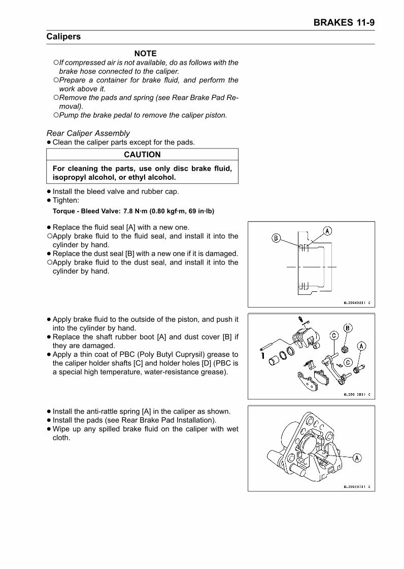
BRAKES 11-9Calipers
NOTEIf compressed air is not available, do as follows with thebrake hose connected to the caliper.Prepare a container for brake fluid, and perform thework above it.Remove the pads and spring (see Rear Brake Pad Re-moval).Pump the brake pedal to remove the caliper piston.
Rear Caliper Assembly•Clean the caliper parts except for the pads.
CAUTIONFor cleaning the parts, use only disc brake fluid,isopropyl alcohol, or ethyl alcohol.
• Install the bleed valve and rubber cap.• Tighten:Torque - Bleed Valve: 7.8 N·m (0.80 kgf·m, 69 in·lb)
•Replace the fluid seal [A] with a new one.Apply brake fluid to the fluid seal, and install it into thecylinder by hand.•Replace the dust seal [B] with a new one if it is damaged.Apply brake fluid to the dust seal, and install it into thecylinder by hand.
• Apply brake fluid to the outside of the piston, and push itinto the cylinder by hand.•Replace the shaft rubber boot [A] and dust cover [B] ifthey are damaged.• Apply a thin coat of PBC (Poly Butyl Cuprysil) grease tothe caliper holder shafts [C] and holder holes [D] (PBC isa special high temperature, water-resistance grease).
• Install the anti-rattle spring [A] in the caliper as shown.• Install the pads (see Rear Brake Pad Installation).•Wipe up any spilled brake fluid on the caliper with wetcloth.
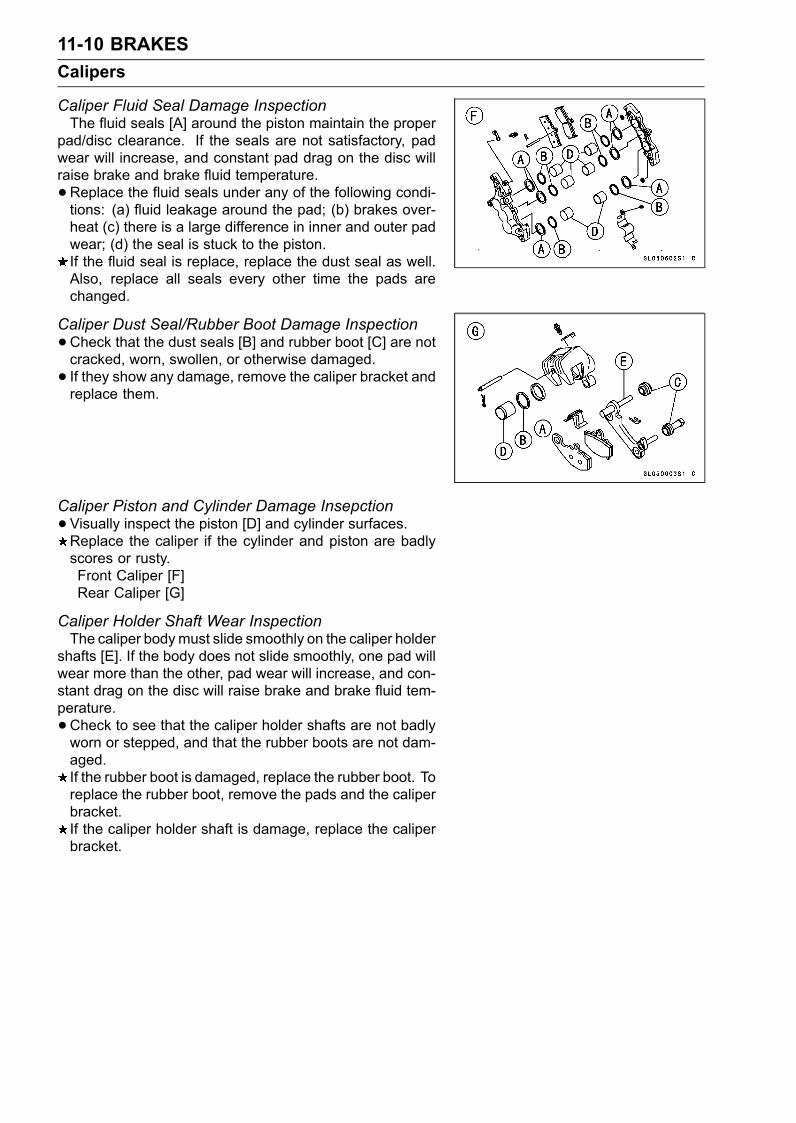
11-10 BRAKESCalipers
Caliper Fluid Seal Damage InspectionThe fluid seals [A] around the piston maintain the proper
pad/disc clearance. If the seals are not satisfactory, padwear will increase, and constant pad drag on the disc willraise brake and brake fluid temperature.•Replace the fluid seals under any of the following condi-tions: (a) fluid leakage around the pad; (b) brakes over-heat (c) there is a large difference in inner and outer padwear; (d) the seal is stuck to the piston.If the fluid seal is replace, replace the dust seal as well.Also, replace all seals every other time the pads arechanged.
Caliper Dust Seal/Rubber Boot Damage Inspection•Check that the dust seals [B] and rubber boot [C] are notcracked, worn, swollen, or otherwise damaged.• If they show any damage, remove the caliper bracket andreplace them.
Caliper Piston and Cylinder Damage Insepction•Visually inspect the piston [D] and cylinder surfaces.Replace the caliper if the cylinder and piston are badlyscores or rusty.Front Caliper [F]Rear Caliper [G]
Caliper Holder Shaft Wear InspectionThe caliper bodymust slide smoothly on the caliper holder
shafts [E]. If the body does not slide smoothly, one pad willwear more than the other, pad wear will increase, and con-stant drag on the disc will raise brake and brake fluid tem-perature.•Check to see that the caliper holder shafts are not badlyworn or stepped, and that the rubber boots are not dam-aged.If the rubber boot is damaged, replace the rubber boot. Toreplace the rubber boot, remove the pads and the caliperbracket.If the caliper holder shaft is damage, replace the caliperbracket.
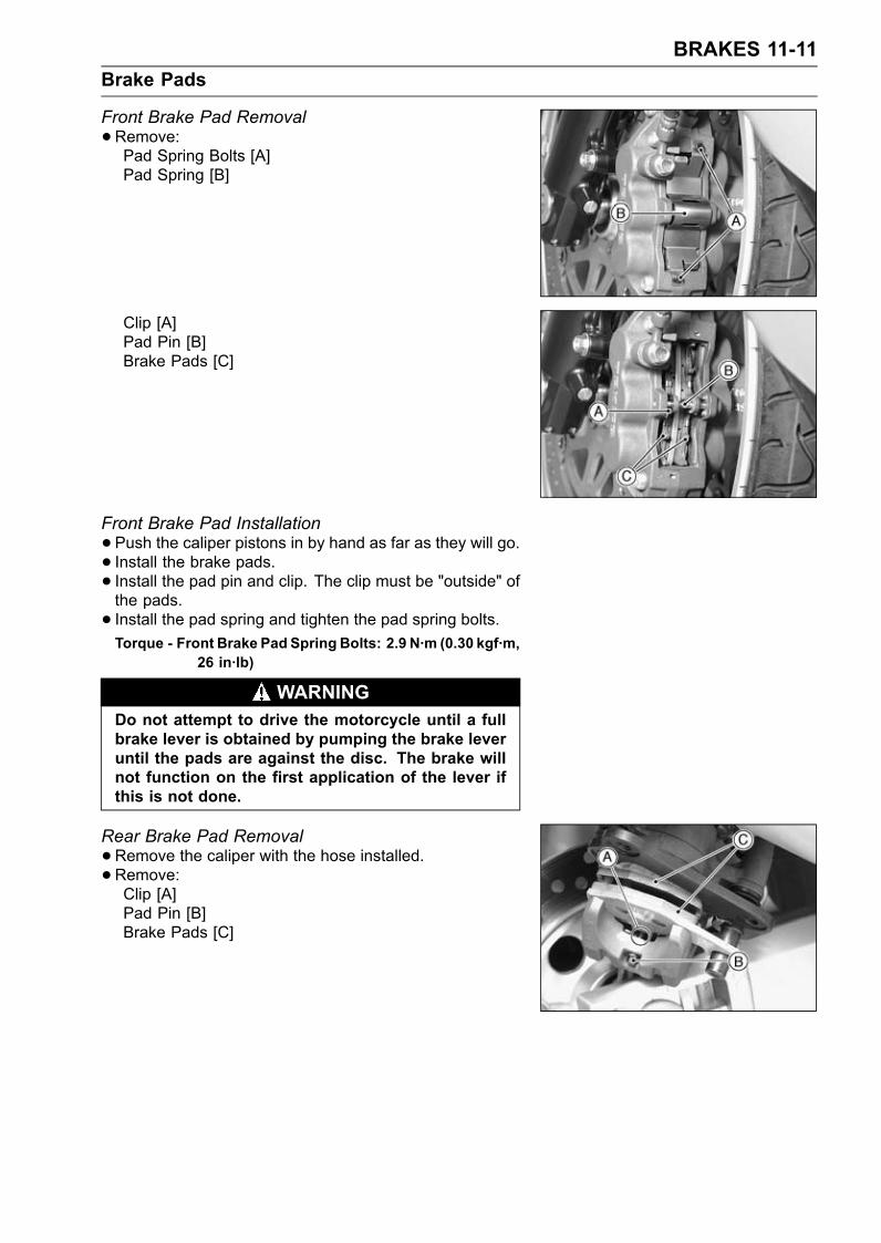
BRAKES 11-11Brake Pads
Front Brake Pad Removal•Remove:Pad Spring Bolts [A]Pad Spring [B]
Clip [A]Pad Pin [B]Brake Pads [C]
Front Brake Pad Installation•Push the caliper pistons in by hand as far as they will go.• Install the brake pads.• Install the pad pin and clip. The clip must be "outside" ofthe pads.• Install the pad spring and tighten the pad spring bolts.Torque - Front Brake Pad Spring Bolts: 2.9 N·m (0.30 kgf·m,
26 in·lb)
WARNINGDo not attempt to drive the motorcycle until a fullbrake lever is obtained by pumping the brake leveruntil the pads are against the disc. The brake willnot function on the first application of the lever ifthis is not done.
Rear Brake Pad Removal•Remove the caliper with the hose installed.•Remove:Clip [A]Pad Pin [B]Brake Pads [C]
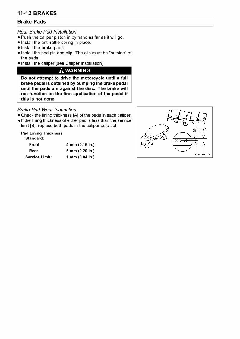
11-12 BRAKESBrake Pads
Rear Brake Pad Installation•Push the caliper piston in by hand as far as it will go.• Install the anti-rattle spring in place.• Install the brake pads.• Install the pad pin and clip. The clip must be "outside" ofthe pads.• Install the caliper (see Caliper Installation).
WARNINGDo not attempt to drive the motorcycle until a fullbrake pedal is obtained by pumping the brake pedaluntil the pads are against the disc. The brake willnot function on the first application of the pedal ifthis is not done.
Brake Pad Wear Inspection•Check the lining thickness [A] of the pads in each caliper.If the lining thickness of either pad is less than the servicelimit [B], replace both pads in the caliper as a set.
Pad Lining ThicknessStandard:Front 4 mm (0.16 in.)Rear 5 mm (0.20 in.)
Service Limit: 1 mm (0.04 in.)
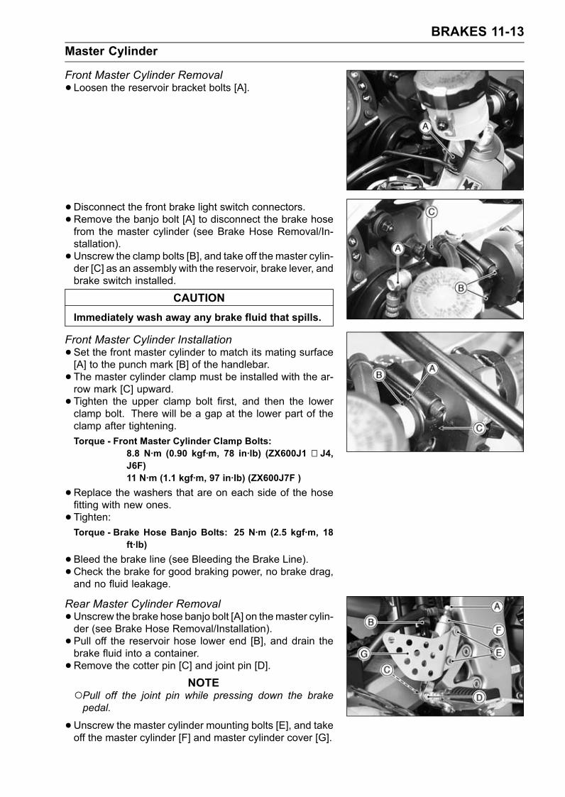
BRAKES 11-13Master Cylinder
Front Master Cylinder Removal• Loosen the reservoir bracket bolts [A].
• Disconnect the front brake light switch connectors.•Remove the banjo bolt [A] to disconnect the brake hosefrom the master cylinder (see Brake Hose Removal/In-stallation).• Unscrew the clamp bolts [B], and take off the master cylin-der [C] as an assembly with the reservoir, brake lever, andbrake switch installed.
CAUTIONImmediately wash away any brake fluid that spills.
Front Master Cylinder Installation•Set the front master cylinder to match its mating surface[A] to the punch mark [B] of the handlebar.• The master cylinder clamp must be installed with the ar-row mark [C] upward.• Tighten the upper clamp bolt first, and then the lowerclamp bolt. There will be a gap at the lower part of theclamp after tightening.Torque - Front Master Cylinder Clamp Bolts:
8.8 N·m (0.90 kgf·m, 78 in·lb) (ZX600J1 ∼ J4,J6F)11 N·m (1.1 kgf·m, 97 in·lb) (ZX600J7F )
•Replace the washers that are on each side of the hosefitting with new ones.• Tighten:Torque - Brake Hose Banjo Bolts: 25 N·m (2.5 kgf·m, 18
ft·lb)
•Bleed the brake line (see Bleeding the Brake Line).• Check the brake for good braking power, no brake drag,and no fluid leakage.
Rear Master Cylinder Removal•Unscrew the brake hose banjo bolt [A] on themaster cylin-der (see Brake Hose Removal/Installation).• Pull off the reservoir hose lower end [B], and drain thebrake fluid into a container.• Remove the cotter pin [C] and joint pin [D].
NOTEPull off the joint pin while pressing down the brakepedal.
•Unscrew the master cylinder mounting bolts [E], and takeoff the master cylinder [F] and master cylinder cover [G].
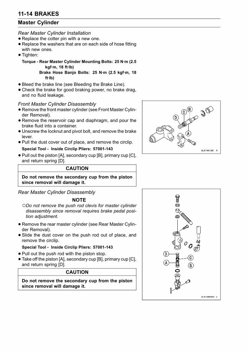
11-14 BRAKESMaster Cylinder
Rear Master Cylinder Installation•Replace the cotter pin with a new one.•Replace the washers that are on each side of hose fittingwith new ones.• Tighten:Torque - Rear Master Cylinder Mounting Bolts: 25 N·m (2.5
kgf·m, 18 ft·lb)Brake Hose Banjo Bolts: 25 N·m (2.5 kgf·m, 18ft·lb)
•Bleed the brake line (see Bleeding the Brake Line).• Check the brake for good braking power, no brake drag,and no fluid leakage.
Front Master Cylinder Disassembly•Remove the front master cylinder (see Front Master Cylin-der Removal).• Remove the reservoir cap and diaphragm, and pour thebrake fluid into a container.• Unscrew the locknut and pivot bolt, and remove the brakelever.• Pull the dust cover out of place, and remove the circlip.Special Tool - Inside Circlip Pliers: 57001-143
•Pull out the piston [A], secondary cup [B], primary cup [C],and return spring [D].
CAUTIONDo not remove the secondary cup from the pistonsince removal will damage it.
Rear Master Cylinder DisassemblyNOTE
Do not remove the push rod clevis for master cylinderdisassembly since removal requires brake pedal posi-tion adjustment.
•Remove the rear master cylinder (see Rear Master Cylin-der Removal).• Slide the dust cover on the push rod out of place, andremove the circlip.Special Tool - Inside Circlip Pliers: 57001-143
•Pull out the push rod with the piston stop.• Take off the piston [A], secondary cup [B], primary cup [C],and return spring [D].
CAUTIONDo not remove the secondary cup from the pistonsince removal will damage it.
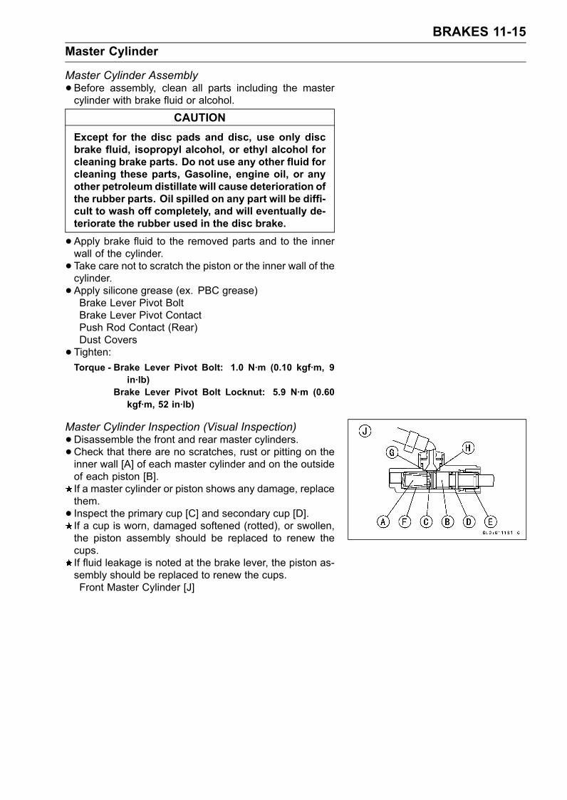
BRAKES 11-15Master Cylinder
Master Cylinder Assembly•Before assembly, clean all parts including the mastercylinder with brake fluid or alcohol.
CAUTIONExcept for the disc pads and disc, use only discbrake fluid, isopropyl alcohol, or ethyl alcohol forcleaning brake parts. Do not use any other fluid forcleaning these parts, Gasoline, engine oil, or anyother petroleum distillate will cause deterioration ofthe rubber parts. Oil spilled on any part will be diffi-cult to wash off completely, and will eventually de-teriorate the rubber used in the disc brake.
•Apply brake fluid to the removed parts and to the innerwall of the cylinder.• Take care not to scratch the piston or the inner wall of thecylinder.• Apply silicone grease (ex. PBC grease)Brake Lever Pivot BoltBrake Lever Pivot ContactPush Rod Contact (Rear)Dust Covers• Tighten:Torque - Brake Lever Pivot Bolt: 1.0 N·m (0.10 kgf·m, 9
in·lb)Brake Lever Pivot Bolt Locknut: 5.9 N·m (0.60kgf·m, 52 in·lb)
Master Cylinder Inspection (Visual Inspection)•Disassemble the front and rear master cylinders.•Check that there are no scratches, rust or pitting on theinner wall [A] of each master cylinder and on the outsideof each piston [B].If a master cylinder or piston shows any damage, replacethem.• Inspect the primary cup [C] and secondary cup [D].If a cup is worn, damaged softened (rotted), or swollen,the piston assembly should be replaced to renew thecups.If fluid leakage is noted at the brake lever, the piston as-sembly should be replaced to renew the cups.Front Master Cylinder [J]
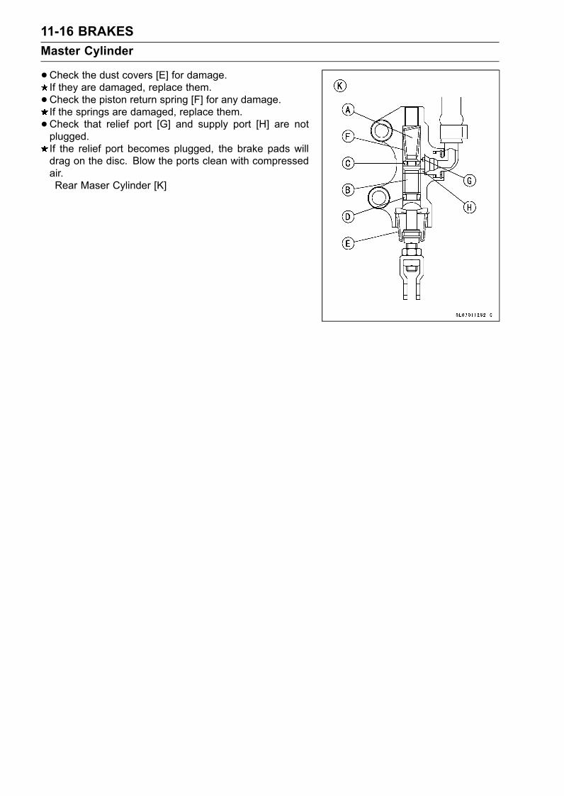
11-16 BRAKESMaster Cylinder
•Check the dust covers [E] for damage.If they are damaged, replace them.•Check the piston return spring [F] for any damage.If the springs are damaged, replace them.•Check that relief port [G] and supply port [H] are notplugged.If the relief port becomes plugged, the brake pads willdrag on the disc. Blow the ports clean with compressedair.Rear Maser Cylinder [K]
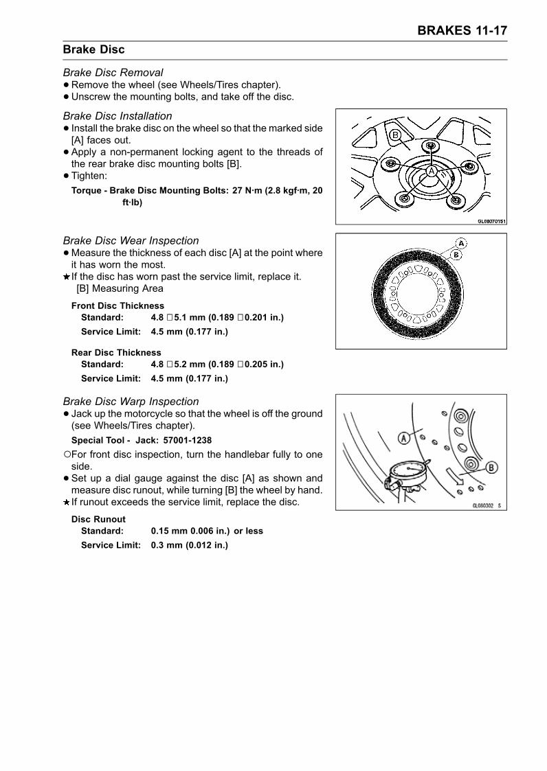
BRAKES 11-17Brake Disc
Brake Disc Removal•Remove the wheel (see Wheels/Tires chapter).• Unscrew the mounting bolts, and take off the disc.Brake Disc Installation• Install the brake disc on the wheel so that the marked side[A] faces out.• Apply a non-permanent locking agent to the threads ofthe rear brake disc mounting bolts [B].• Tighten:Torque - Brake Disc Mounting Bolts: 27 N·m (2.8 kgf·m, 20
ft·lb)
Brake Disc Wear Inspection•Measure the thickness of each disc [A] at the point whereit has worn the most.If the disc has worn past the service limit, replace it.[B] Measuring Area
Front Disc ThicknessStandard: 4.8 ∼ 5.1 mm (0.189 ∼ 0.201 in.)Service Limit: 4.5 mm (0.177 in.)
Rear Disc ThicknessStandard: 4.8 ∼ 5.2 mm (0.189 ∼ 0.205 in.)Service Limit: 4.5 mm (0.177 in.)
Brake Disc Warp Inspection• Jack up the motorcycle so that the wheel is off the ground(see Wheels/Tires chapter).Special Tool - Jack: 57001-1238For front disc inspection, turn the handlebar fully to oneside.• Set up a dial gauge against the disc [A] as shown andmeasure disc runout, while turning [B] the wheel by hand.If runout exceeds the service limit, replace the disc.
Disc RunoutStandard: 0.15 mm 0.006 in.) or lessService Limit: 0.3 mm (0.012 in.)
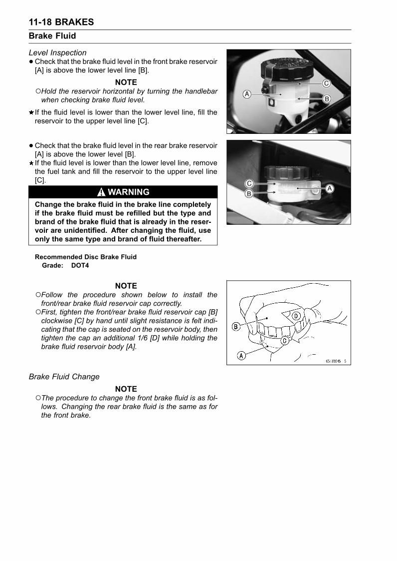
11-18 BRAKESBrake Fluid
Level Inspection•Check that the brake fluid level in the front brake reservoir[A] is above the lower level line [B].
NOTEHold the reservoir horizontal by turning the handlebarwhen checking brake fluid level.
If the fluid level is lower than the lower level line, fill thereservoir to the upper level line [C].
• Check that the brake fluid level in the rear brake reservoir[A] is above the lower level [B].If the fluid level is lower than the lower level line, removethe fuel tank and fill the reservoir to the upper level line[C].
WARNINGChange the brake fluid in the brake line completelyif the brake fluid must be refilled but the type andbrand of the brake fluid that is already in the reser-voir are unidentified. After changing the fluid, useonly the same type and brand of fluid thereafter.
Recommended Disc Brake FluidGrade: DOT4
NOTEFollow the procedure shown below to install thefront/rear brake fluid reservoir cap correctly.First, tighten the front/rear brake fluid reservoir cap [B]clockwise [C] by hand until slight resistance is felt indi-cating that the cap is seated on the reservoir body, thentighten the cap an additional 1/6 [D] while holding thebrake fluid reservoir body [A].
Brake Fluid ChangeNOTE
The procedure to change the front brake fluid is as fol-lows. Changing the rear brake fluid is the same as forthe front brake.
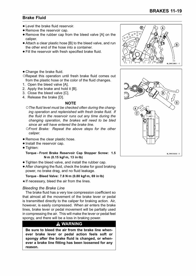
BRAKES 11-19Brake Fluid
• Level the brake fluid reservoir.• Remove the reservoir cap.•Remove the rubber cap from the bleed valve [A] on thecaliper.• Attach a clear plastic hose [B] to the bleed valve, and runthe other end of the hose into a container.• Fill the reservoir with fresh specified brake fluid.
•Change the brake fluid.Repeat this operation until fresh brake fluid comes outfrom the plastic hose or the color of the fluid changes.
1. Open the bleed valve [A].2. Apply the brake and hold it [B].3. Close the bleed valve [C].4. Release the brake [D].
NOTEThe fluid level must be checked often during the chang-ing operation and replenished with fresh brake fluid. Ifthe fluid in the reservoir runs out any time during thechanging operation, the brakes will need to be bledsince air will have entered the brake line.Front Brake: Repeat the above steps for the othercaliper.
•Remove the clear plastic hose.• Install the reservoir cap.• Tighten:Torque - Front Brake Reservoir Cap Stopper Screw: 1.5
N·m (0.15 kgf·m, 13 in·lb)
•Tighten the bleed valve, and install the rubber cap.• After changing the fluid, check the brake for good brakingpower, no brake drag, and no fluid leakage.Torque - Bleed Valve: 7.8 N·m (0.80 kgf·m, 69 in·lb)If necessary, bleed the air from the lines.
Bleeding the Brake LineThe brake fluid has a very low compression coefficient so
that almost all the movement of the brake lever or pedalis transmitted directly to the caliper for braking action. Air,however, is easily compressed. When air enters the brakelines, brake lever or pedal movement will be partially usedin compressing the air. This will make the lever or pedal feelspongy, and there will be a loss in braking power.
WARNINGBe sure to bleed the air from the brake line when-ever brake lever or pedal action feels soft orspongy after the brake fluid is changed, or when-ever a brake line fitting has been loosened for anyreason.
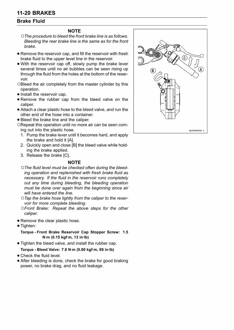
11-20 BRAKESBrake Fluid
NOTEThe procedure to bleed the front brake line is as follows.Bleeding the rear brake line is the same as for the frontbrake.
•Remove the reservoir cap, and fill the reservoir with freshbrake fluid to the upper level line in the reservoir.•With the reservoir cap off, slowly pump the brake leverseveral times until no air bubbles can be seen rising upthrough the fluid from the holes at the bottom of the reser-voir.Bleed the air completely from the master cylinder by thisoperation.• Install the reservoir cap.•Remove the rubber cap from the bleed valve on thecaliper.• Attach a clear plastic hose to the bleed valve, and run theother end of the hose into a container.• Bleed the brake line and the caliper.Repeat this operation until no more air can be seen com-ing out into the plastic hose.1. Pump the brake lever until it becomes hard, and applythe brake and hold it [A].
2. Quickly open and close [B] the bleed valve while hold-ing the brake applied.
3. Release the brake [C].
NOTEThe fluid level must be checked often during the bleed-ing operation and replenished with fresh brake fluid asnecessary. If the fluid in the reservoir runs completelyout any time during bleeding, the bleeding operationmust be done over again from the beginning since airwill have entered the line.Tap the brake hose lightly from the caliper to the reser-voir for more complete bleeding.Front Brake: Repeat the above steps for the othercaliper.
•Remove the clear plastic hose.• Tighten:Torque - Front Brake Reservoir Cap Stopper Screw: 1.5
N·m (0.15 kgf·m, 13 in·lb)
•Tighten the bleed valve, and install the rubber cap.Torque - Bleed Valve: 7.8 N·m (0.80 kgf·m, 69 in·lb)
•Check the fluid level.• After bleeding is done, check the brake for good brakingpower, no brake drag, and no fluid leakage.
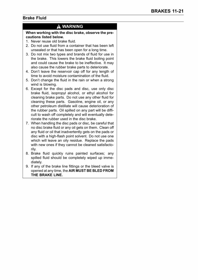
BRAKES 11-21Brake Fluid
WARNINGWhen working with the disc brake, observe the pre-cautions listed below.1. Never reuse old brake fluid.2. Do not use fluid from a container that has been leftunsealed or that has been open for a long time.
3. Do not mix two types and brands of fluid for use inthe brake. This lowers the brake fluid boiling pointand could cause the brake to be ineffective. It mayalso cause the rubber brake parts to deteriorate.
4. Don’t leave the reservoir cap off for any length oftime to avoid moisture contamination of the fluid.
5. Don’t change the fluid in the rain or when a strongwind is blowing.
6. Except for the disc pads and disc, use only discbrake fluid, isopropyl alcohol, or ethyl alcohol forcleaning brake parts. Do not use any other fluid forcleaning these parts. Gasoline, engine oil, or anyother petroleum distillate will cause deterioration ofthe rubber parts. Oil spilled on any part will be diffi-cult to wash off completely and will eventually dete-riorate the rubber used in the disc brake.
7. When handling the disc pads or disc, be careful thatno disc brake fluid or any oil gets on them. Clean offany fluid or oil that inadvertently gets on the pads ordisc with a high-flash point solvent. Do not use onewhich will leave an oily residue. Replace the padswith new ones if they cannot be cleaned satisfacto-rily.
8. Brake fluid quickly ruins painted surfaces; anyspilled fluid should be completely wiped up imme-diately.
9. If any of the brake line fittings or the bleed valve isopened at any time, theAIRMUSTBEBLED FROMTHE BRAKE LINE.
11-22 BRAKESBrake Hose
Brake Hose Removal/InstallationCAUTION
Brake fluid quickly ruins painted or plastic sur-faces; any spilled fluid should be completely wipedup immediately with wet cloth.
•When removing the brake hose, take care not to spill thebrake fluid on the painted or plastic parts.•When removing the brake hose, temporarily secure theend of the brake hose to some high place to keep fluidloss to a minimum.• There are washers on each side of the brake hose fitting.Replace them with new ones when installing.•When installing the hoses, avoid sharp bending, kinking,flattening or twisting, and route the hoses according toCable, Wire, and Hose Routing section in General Infor-mation chapter.• Tighten:Torque - Brake Hose Banjo Bolts: 25 N·m (2.5 kgf·m, 18
ft·lb)
•Bleed the brake line after installing the brake hose (seeBleeding the Brake Line).
Brake Hose Inspection•The high pressure inside the brake line can cause fluid toleak or the hose to burst if the line is not properly main-tained. Bend and twist the rubber hose while examiningit.Replace it if any cracks or bulges are noticed.
SUSPENSION 12-1
12
SuspensionTable of Contents
Exploded View........................................................................................................................ 12-2Specifications ......................................................................................................................... 12-4Front Fork ............................................................................................................................... 12-6
Rebound Damping Force Adjustment............................................................................... 12-6Compression Damping Force Adjustment ........................................................................ 12-6Spring Preload Adjustment ............................................................................................... 12-7Front Fork Removal (each fork leg) .................................................................................. 12-8Front Fork Installation ....................................................................................................... 12-8Fork Oil Change................................................................................................................ 12-8Front Fork Disassembly .................................................................................................... 12-11Front Fork Assembly......................................................................................................... 12-12Inner Tube, Outer Tube Inspection ................................................................................... 12-13Dust Seal Inspection ......................................................................................................... 12-14Spring Tension .................................................................................................................. 12-14
Rear Shock Absorber ............................................................................................................. 12-15Rebound Damping Force Adjustment............................................................................... 12-15Compression Damping Force Adjustment ........................................................................ 12-15Spring Preload Adjustment ............................................................................................... 12-16Rear Shock Absorber Removal ........................................................................................ 12-16Rear Shock Absorber Installation ..................................................................................... 12-17Rear Shock Absorber Inspection ...................................................................................... 12-17Rear Shock Absorber Scrapping ...................................................................................... 12-17
Swingarm................................................................................................................................ 12-18Swingarm Removal........................................................................................................... 12-18Swingarm Installation........................................................................................................ 12-18Swingarm Bearing Removal ............................................................................................. 12-18Swingarm Bearing Installation .......................................................................................... 12-18Swingarm Bearing, Sleeve Inspection .............................................................................. 12-19Swingarm Lubrication ....................................................................................................... 12-19
Tie-Rod, Rocker Arm.............................................................................................................. 12-20Tie-Rod Removal .............................................................................................................. 12-20Tie-Rod Installation ........................................................................................................... 12-20Rocker Arm Removal........................................................................................................ 12-20Rocker Arm Installation..................................................................................................... 12-20Rocker Arm/Tie-Rod Bearing, Sleeve Inspection ............................................................. 12-21Rocker Arm/Tie-Rod Lubrication....................................................................................... 12-21
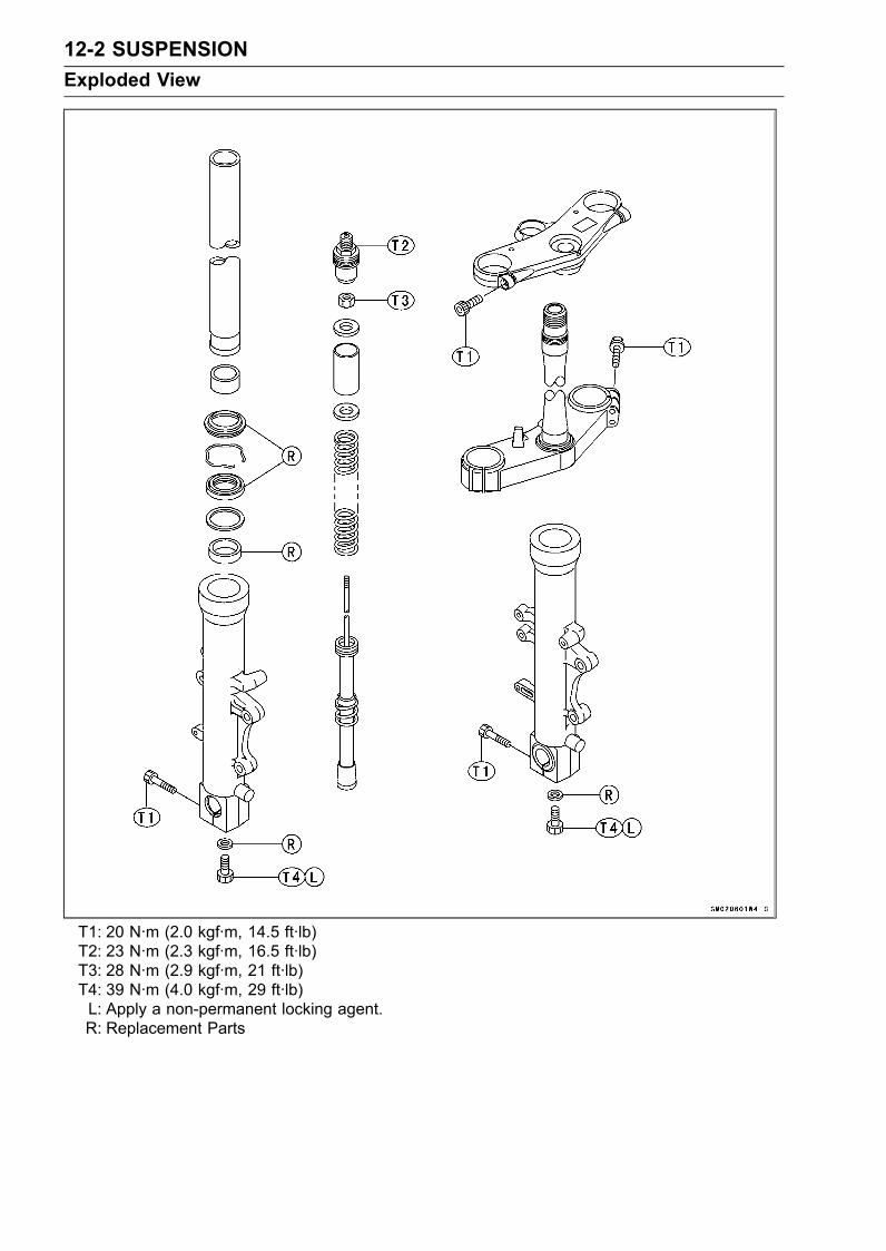
12-2 SUSPENSIONExploded View
T1: 20 N·m (2.0 kgf·m, 14.5 ft·lb)T2: 23 N·m (2.3 kgf·m, 16.5 ft·lb)T3: 28 N·m (2.9 kgf·m, 21 ft·lb)T4: 39 N·m (4.0 kgf·m, 29 ft·lb)L: Apply a non-permanent locking agent.R: Replacement Parts
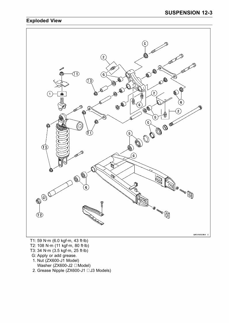
SUSPENSION 12-3Exploded View
T1: 59 N·m (6.0 kgf·m, 43 ft·lb)T2: 108 N·m (11 kgf·m, 80 ft·lb)T3: 34 N·m (3.5 kgf·m, 25 ft·lb)G: Apply or add grease.1. Nut (ZX600-J1 Model)Washer (ZX600-J2 ∼ Model)
2. Grease Nipple (ZX600-J1 ∼ J3 Models)
12-4 SUSPENSIONSpecifications
Item StandardFront Fork (Per One Unit)Fork Inner Tube Diameter 46 mm (1.81 in.)Air Pressure Atmospheric pressure (Non-adjustable)Rebound Damper Setting 7th click from the first click of the fully clockwise position
(ZX600-J1 ∼ J3)(Usable Range: 1 ←→ 12 clicks)
1 1/2 turns out from fully clockwise position (ZX600-J4 ∼ (US),ZX600J6F ∼ (CA))(Usable Range: fully clockwise position ∼ 3 turns out)
Compression Damper Setting 9th click from the first click of the fully clockwise position(ZX600-J1 ∼ J3)(Usable Range: 1 ←→ 12 clicks)
2 turns out from fully clockwise position (ZX600-J4 ∼ (US),ZX600J6F ∼ (CA))(Usable Range: fully clockwise position ∼ 3 turns out)
Fork Spring Preload Setting Adjuster protrusion is 14 mm (0.55 in.)(Usable Range: 5 ∼ 20 mm (0.20 ∼ 0.79 in.))
Fork Oil Viscosity KHL34 (KAYABA G10) or equivalentFork Oil Capacity 537 ±4 mL (18.2 ±0.1 US oz) (completely dry) (ZX600-J1 ∼ J3)
541 ±4 mL (18.3 ±0.1 US oz) (completely dry) (ZX600-J4 ∼ (US),ZX600J6F ∼ (CA))approx. 455 mL (15.4 US oz) (when changing oil) (ZX600-J1 ∼ J3)approx. 459 mL (15.5 US oz) (when changing oil) (ZX600-J4 ∼(US), ZX600J6F ∼ (CA))
Fork Oil Level Fully compressed, without fork spring, below from inner tube top116 ±2 mm (4.57 ±0.08 in.) (ZX600-J1 ∼ J3)Fully compressed, without fork spring, below from inner tube top113 ±2 mm (4.45 ±0.08 in.) (ZX600-J4 ∼ (US), ZX600J6F ∼ (CA))
Fork Spring Free Length 234.6 mm (9.24 in.) (Service limit 230 mm (9.06 in.))Rear Shock AbsorberRebound Damper Set 10th click from the fist click of the fully clockwise position
(ZX600-J1 ∼ J3)(Usable Range: 1 ←→ 18 clicks)
2 1/2 turns out from fully clockwise position (ZX600-J4 ∼ (US),ZX600J6F ∼ (CA))(Usable Range: fully clockwise position ∼ 5 turns out)
Compression Damper Set 10th click from the first click of the fully clockwise position(ZX600-J1 ∼ J3)(Usable Range: 1 ←→ 20 clicks)
2 1/2 turns out from fully clockwise position (ZX600-J4 ∼ (US),ZX600J6F ∼ (CA))(Usable Range: fully clockwise position ∼ 4 1/2 turns out)
SUSPENSION 12-5Specifications
Item StandardSpring Preload SettingPositionStandard Spring length 180 mm (7.09 in.)Usable Range Spring length 182 mm (7.17 in.) to 170 mm (6.69 in.)
(weaker to stronger)Gas Pressure 980 kPa (10 kg/cm², 142 psi, Non-adjustable)CA: Canada ModelUS: United States Model
Special Tools - Fork Piston Rod Puller, M12 × 1.25: 57001-1289Fork Oil Level Gauge: 57001-1290Fork Outer Tube Weight: 57001-1218Fork Cylinder Holder, Hex 24 × 19.5: 57001-1406Front Fork Oil Seal Driver: 57001-1219Hook Wrench: 57001-1101Oil Seal & Bearing Remover: 57001-1058Bearing Driver Set: 57001-1129Inside Circlip Pliers: 57001-143Jack: 57001-1238
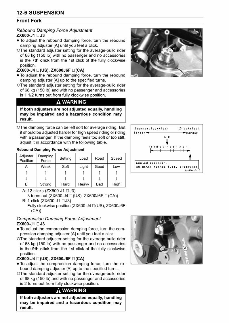
12-6 SUSPENSIONFront Fork
Rebound Damping Force AdjustmentZX600-J1 ∼ J3•To adjust the rebound damping force, turn the rebounddamping adjuster [A] until you feel a click.The standard adjuster setting for the average-build riderof 68 kg (150 lb) with no passenger and no accessoriesis the 7th click from the 1st click of the fully clockwiseposition.
ZX600-J4 ∼ (US), ZX600J6F ∼ (CA)•To adjust the rebound damping force, turn the rebounddamping adjuster [A] up to the specified turns.The standard adjuster setting for the average-build riderof 68 kg (150 lb) and with no passenger and accessoriesis 1 1/2 turns out from fully clockwise position.
WARNINGIf both adjusters are not adjusted equally, handlingmay be impaired and a hazardous condition mayresult.
The damping force can be left soft for average riding. Butit should be adjusted harder for high speed riding or ridingwith a passenger. If the damping feels too soft or too stiff,adjust it in accordance with the following table.
Rebound Damping Force AdjustmentAdjusterPosition
DampingForce Setting Load Road Speed
A Weak Soft Light Good Low↑ ↑ ↑ ↑ ↑ ↑↓ ↓ ↓ ↓ ↓ ↓B Strong Hard Heavy Bad High
A: 12 clicks (ZX600-J1 ∼ J3)3 turns out (ZX600-J4 ∼ (US), ZX600J6F ∼ (CA))
B: 1 click (ZX600-J1 ∼ J3)Fully clockwise position (ZX600-J4 ∼ (US), ZX600J6F∼ (CA))
Compression Damping Force AdjustmentZX600-J1 ∼ J3•To adjust the compression damping force, turn the com-pression damping adjuster [A] until you feel a click.The standard adjuster setting for the average-build riderof 68 kg (150 lb) with no passenger and no accessoriesis the 9th click from the 1st click of the fully clockwiseposition.
ZX600-J4 ∼ (US), ZX600J6F ∼ (CA)•To adjust the compression damping force, turn the re-bound damping adjuster [A] up to the specified turns.The standard adjuster setting for the overage-build riderof 68 kg (150 lb) and with no passenger and accessoriesis 2 turns out from fully clockwise position.
WARNINGIf both adjusters are not adjusted equally, handlingmay be impaired and a hazardous condition mayresult.
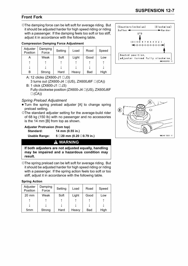
SUSPENSION 12-7Front Fork
The damping force can be left soft for average riding. Butit should be adjusted harder for high speed riding or ridingwith a passenger. If the damping feels too soft or too stiff,adjust it in accordance with the following table.
Compression Damping Force AdjustmentAdjusterPosition
DampingForce Setting Load Road Speed
A Weak Soft Light Good Low↑ ↑ ↑ ↑ ↑ ↑↓ ↓ ↓ ↓ ↓ ↓B Strong Hard Heavy Bad High
A: 12 clicks (ZX600-J1 ∼ J3)3 turns out (ZX600-J4 ∼ (US), ZX600J6F ∼ (CA))
B: 1 click (ZX600-J1 ∼ J3)Fully clockwise position (ZX600-J4 ∼ (US), ZX600J6F∼ (CA))
Spring Preload Adjustment•Turn the spring preload adjuster [A] to change springpreload setting.The standard adjuster setting for the average-build riderof 68 kg (150 lb) with no passenger and no accessoriesis the 14 mm [B] from top as shown.
Adjuster Protrusion (from top)Standard: 14 mm (0.55 in.)Usable Range: 5 ∼ 20 mm (0.20 ∼ 0.79 in.)
WARNINGIf both adjusters are not adjusted equally, handlingmay be impaired and a hazardous condition mayresult.
The spring preload can be left soft for average riding. Butit should be adjusted harder for high speed riding or ridingwith a passenger. If the spring action feels too soft or toostiff, adjust it in accordance with the following table.
Spring ActionAdjusterPosition
DampingForce Setting Load Road Speed
20 mm Weak Soft Light Good Low↑ ↑ ↑ ↑ ↑ ↑↓ ↓ ↓ ↓ ↓ ↓
5mm Strong Hard Heavy Bad High
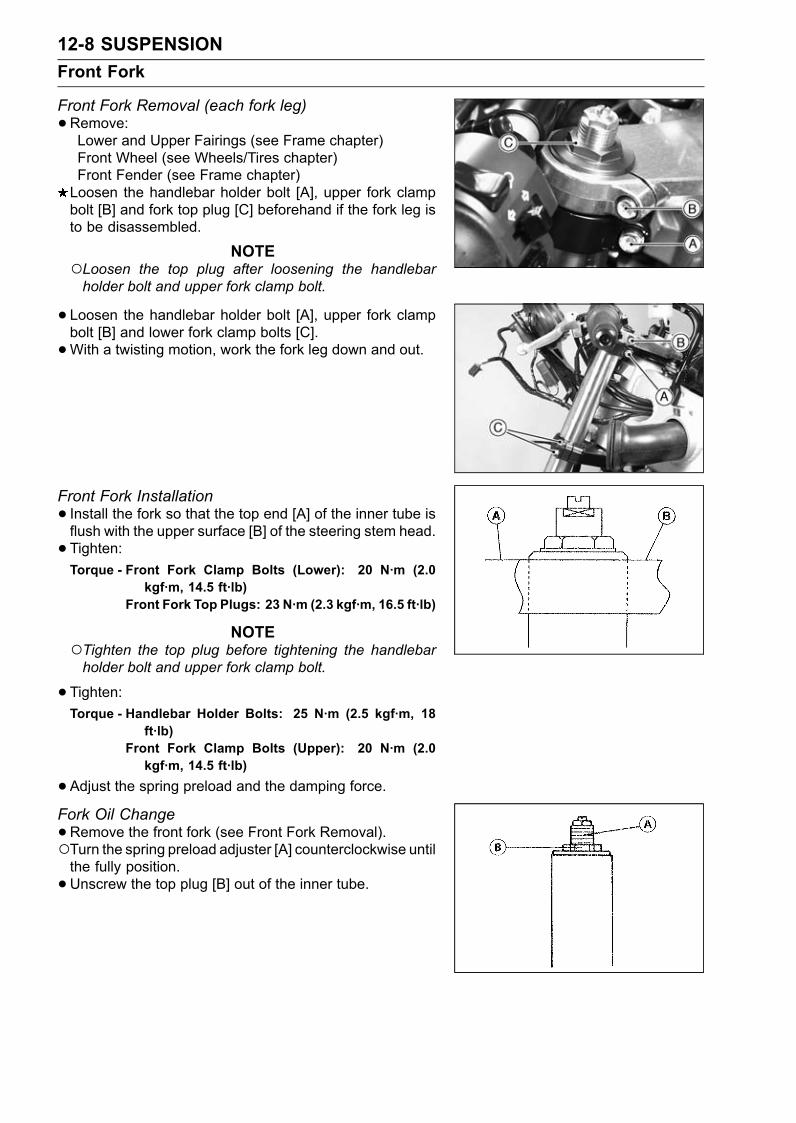
12-8 SUSPENSIONFront Fork
Front Fork Removal (each fork leg)•Remove:Lower and Upper Fairings (see Frame chapter)Front Wheel (see Wheels/Tires chapter)Front Fender (see Frame chapter)Loosen the handlebar holder bolt [A], upper fork clampbolt [B] and fork top plug [C] beforehand if the fork leg isto be disassembled.
NOTELoosen the top plug after loosening the handlebarholder bolt and upper fork clamp bolt.
• Loosen the handlebar holder bolt [A], upper fork clampbolt [B] and lower fork clamp bolts [C].•With a twisting motion, work the fork leg down and out.
Front Fork Installation• Install the fork so that the top end [A] of the inner tube isflush with the upper surface [B] of the steering stem head.• Tighten:Torque - Front Fork Clamp Bolts (Lower): 20 N·m (2.0
kgf·m, 14.5 ft·lb)Front Fork Top Plugs: 23 N·m (2.3 kgf·m, 16.5 ft·lb)
NOTETighten the top plug before tightening the handlebarholder bolt and upper fork clamp bolt.
•Tighten:Torque - Handlebar Holder Bolts: 25 N·m (2.5 kgf·m, 18
ft·lb)Front Fork Clamp Bolts (Upper): 20 N·m (2.0kgf·m, 14.5 ft·lb)
•Adjust the spring preload and the damping force.Fork Oil Change•Remove the front fork (see Front Fork Removal).Turn the spring preload adjuster [A] counterclockwise untilthe fully position.•Unscrew the top plug [B] out of the inner tube.
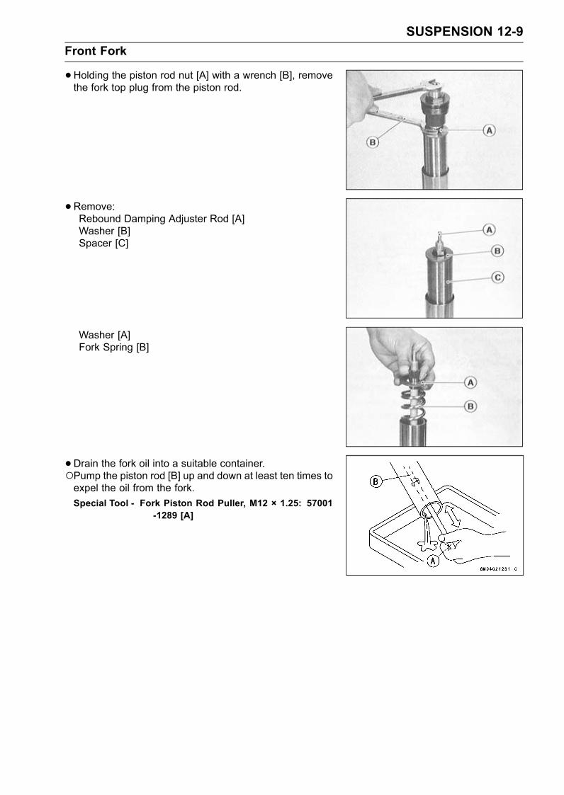
SUSPENSION 12-9Front Fork
•Holding the piston rod nut [A] with a wrench [B], removethe fork top plug from the piston rod.
•Remove:Rebound Damping Adjuster Rod [A]Washer [B]Spacer [C]
Washer [A]Fork Spring [B]
•Drain the fork oil into a suitable container.Pump the piston rod [B] up and down at least ten times toexpel the oil from the fork.Special Tool - Fork Piston Rod Puller, M12 × 1.25: 57001
-1289 [A]
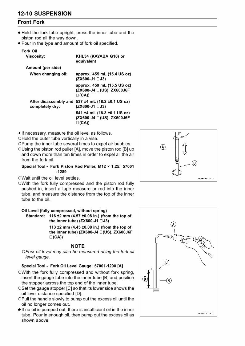
12-10 SUSPENSIONFront Fork
•Hold the fork tube upright, press the inner tube and thepiston rod all the way down.• Pour in the type and amount of fork oil specified.Fork OilViscosity: KHL34 (KAYABA G10) or
equivalentAmount (per side)When changing oil: approx. 455 mL (15.4 US oz)
(ZX600-J1 ∼ J3)approx. 459 mL (15.5 US oz)(ZX600-J4 ∼ (US), ZX600J6F∼ (CA))
After disassembly andcompletely dry:
537 ±4 mL (18.2 ±0.1 US oz)(ZX600-J1 ∼ J3)541 ±4 mL (18.3 ±0.1 US oz)(ZX600-J4 ∼ (US), ZX600J6F∼ (CA))
If necessary, measure the oil level as follows.Hold the outer tube vertically in a vise.Pump the inner tube several times to expel air bubbles.Using the piston rod puller [A], move the piston rod [B] upand down more than ten times in order to expel all the airfrom the fork oil.Special Tool - Fork Piston Rod Puller, M12 × 1.25: 57001
-1289Wait until the oil level settles.With the fork fully compressed and the piston rod fullypushed in, insert a tape measure or rod into the innertube, and measure the distance from the top of the innertube to the oil.
Oil Level (fully compressed, without spring)Standard: 116 ±2 mm (4.57 ±0.08 in.) (from the top of
the inner tube) (ZX600-J1 ∼ J3)113 ±2 mm (4.45 ±0.08 in.) (from the top ofthe inner tube) (ZX600-J4 ∼ (US), ZX600J6F∼ (CA))
NOTEFork oil level may also be measured using the fork oillevel gauge.
Special Tool - Fork Oil Level Gauge: 57001-1290 [A]With the fork fully compressed and without fork spring,insert the gauge tube into the inner tube [B] and positionthe stopper across the top end of the inner tube.Set the gauge stopper [C] so that its lower side shows theoil level distance specified [D].Pull the handle slowly to pump out the excess oil until theoil no longer comes out.If no oil is pumped out, there is insufficient oil in the innertube. Pour in enough oil, then pump out the excess oil asshown above.
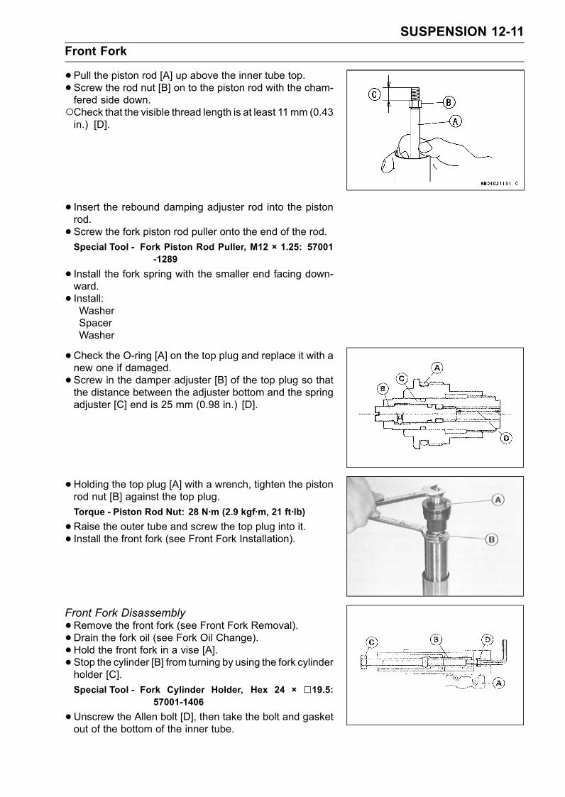
SUSPENSION 12-11Front Fork
•Pull the piston rod [A] up above the inner tube top.• Screw the rod nut [B] on to the piston rod with the cham-fered side down.Check that the visible thread length is at least 11mm (0.43in.) [D].
• Insert the rebound damping adjuster rod into the pistonrod.• Screw the fork piston rod puller onto the end of the rod.Special Tool - Fork Piston Rod Puller, M12 × 1.25: 57001
-1289
• Install the fork spring with the smaller end facing down-ward.• Install:WasherSpacerWasher
•Check the O-ring [A] on the top plug and replace it with anew one if damaged.• Screw in the damper adjuster [B] of the top plug so thatthe distance between the adjuster bottom and the springadjuster [C] end is 25 mm (0.98 in.) [D].
• Holding the top plug [A] with a wrench, tighten the pistonrod nut [B] against the top plug.Torque - Piston Rod Nut: 28 N·m (2.9 kgf·m, 21 ft·lb)
•Raise the outer tube and screw the top plug into it.• Install the front fork (see Front Fork Installation).
Front Fork Disassembly•Remove the front fork (see Front Fork Removal).• Drain the fork oil (see Fork Oil Change).•Hold the front fork in a vise [A].• Stop the cylinder [B] from turning by using the fork cylinderholder [C].Special Tool - Fork Cylinder Holder, Hex 24 × 19.5:
57001-1406
•Unscrew the Allen bolt [D], then take the bolt and gasketout of the bottom of the inner tube.
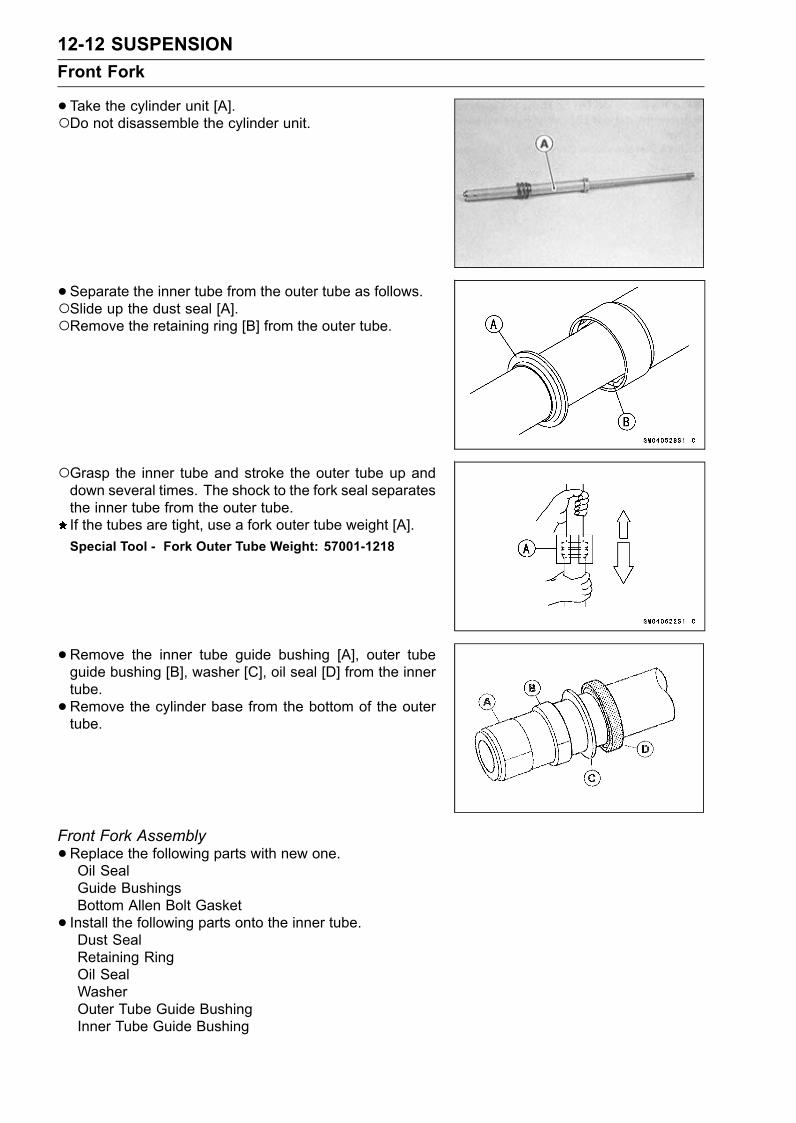
12-12 SUSPENSIONFront Fork
•Take the cylinder unit [A].Do not disassemble the cylinder unit.
• Separate the inner tube from the outer tube as follows.Slide up the dust seal [A].Remove the retaining ring [B] from the outer tube.
Grasp the inner tube and stroke the outer tube up anddown several times. The shock to the fork seal separatesthe inner tube from the outer tube.If the tubes are tight, use a fork outer tube weight [A].Special Tool - Fork Outer Tube Weight: 57001-1218
•Remove the inner tube guide bushing [A], outer tubeguide bushing [B], washer [C], oil seal [D] from the innertube.•Remove the cylinder base from the bottom of the outertube.
Front Fork Assembly•Replace the following parts with new one.Oil SealGuide BushingsBottom Allen Bolt Gasket• Install the following parts onto the inner tube.Dust SealRetaining RingOil SealWasherOuter Tube Guide BushingInner Tube Guide Bushing
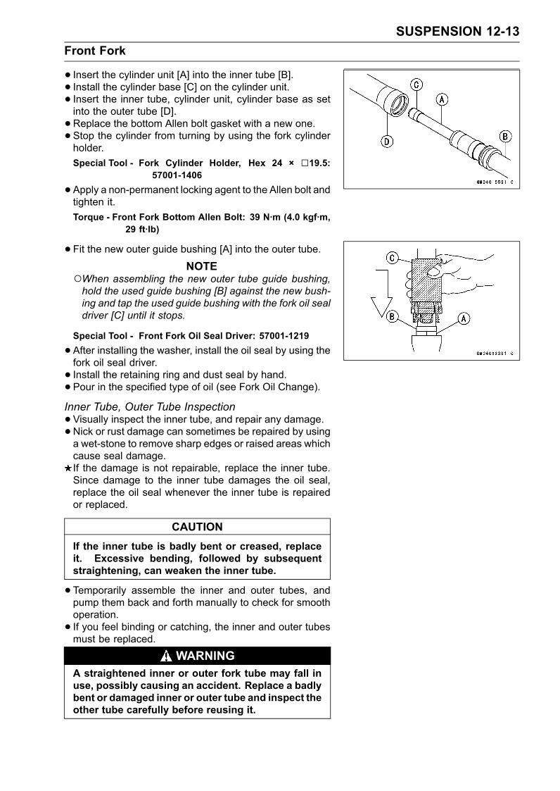
SUSPENSION 12-13Front Fork
• Insert the cylinder unit [A] into the inner tube [B].• Install the cylinder base [C] on the cylinder unit.• Insert the inner tube, cylinder unit, cylinder base as setinto the outer tube [D].• Replace the bottom Allen bolt gasket with a new one.• Stop the cylinder from turning by using the fork cylinderholder.Special Tool - Fork Cylinder Holder, Hex 24 × 19.5:
57001-1406
•Apply a non-permanent locking agent to the Allen bolt andtighten it.Torque - Front Fork Bottom Allen Bolt: 39 N·m (4.0 kgf·m,
29 ft·lb)
•Fit the new outer guide bushing [A] into the outer tube.NOTE
When assembling the new outer tube guide bushing,hold the used guide bushing [B] against the new bush-ing and tap the used guide bushing with the fork oil sealdriver [C] until it stops.
Special Tool - Front Fork Oil Seal Driver: 57001-1219
•After installing the washer, install the oil seal by using thefork oil seal driver.• Install the retaining ring and dust seal by hand.• Pour in the specified type of oil (see Fork Oil Change).Inner Tube, Outer Tube Inspection•Visually inspect the inner tube, and repair any damage.•Nick or rust damage can sometimes be repaired by usinga wet-stone to remove sharp edges or raised areas whichcause seal damage.If the damage is not repairable, replace the inner tube.Since damage to the inner tube damages the oil seal,replace the oil seal whenever the inner tube is repairedor replaced.
CAUTIONIf the inner tube is badly bent or creased, replaceit. Excessive bending, followed by subsequentstraightening, can weaken the inner tube.
•Temporarily assemble the inner and outer tubes, andpump them back and forth manually to check for smoothoperation.• If you feel binding or catching, the inner and outer tubesmust be replaced.
WARNINGA straightened inner or outer fork tube may fall inuse, possibly causing an accident. Replace a badlybent or damaged inner or outer tube and inspect theother tube carefully before reusing it.
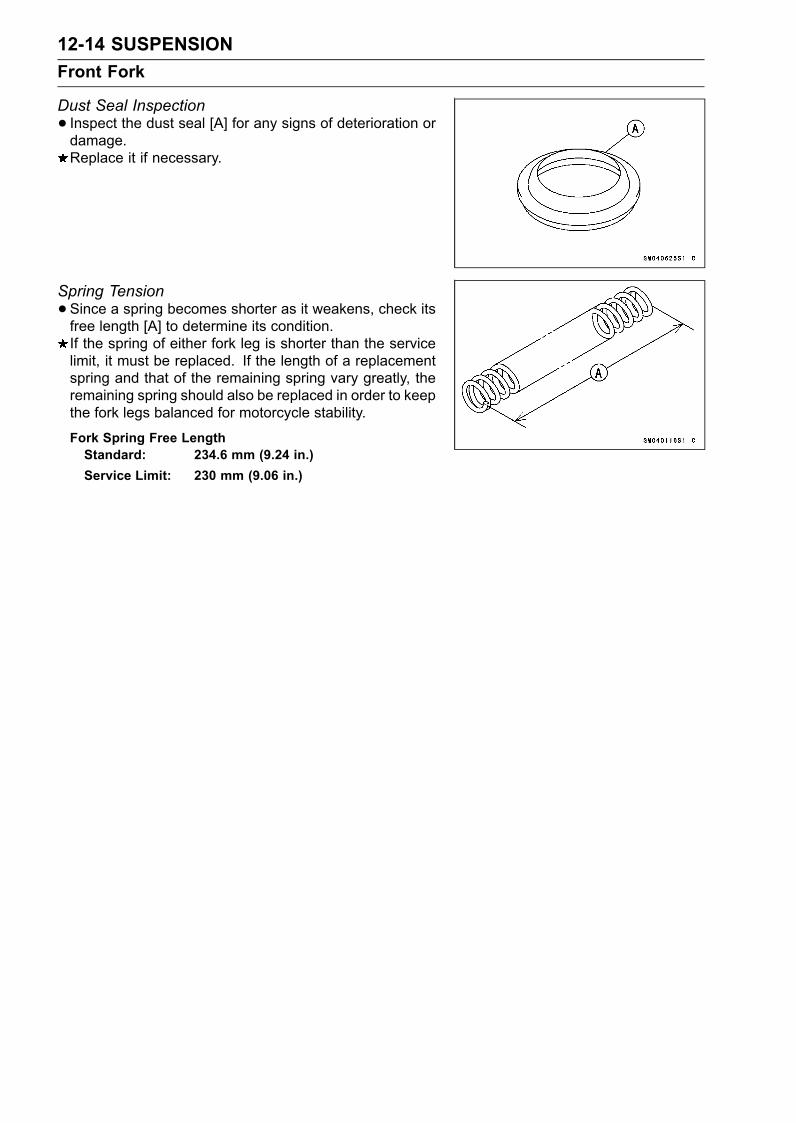
12-14 SUSPENSIONFront Fork
Dust Seal Inspection• Inspect the dust seal [A] for any signs of deterioration ordamage.Replace it if necessary.
Spring Tension•Since a spring becomes shorter as it weakens, check itsfree length [A] to determine its condition.If the spring of either fork leg is shorter than the servicelimit, it must be replaced. If the length of a replacementspring and that of the remaining spring vary greatly, theremaining spring should also be replaced in order to keepthe fork legs balanced for motorcycle stability.
Fork Spring Free LengthStandard: 234.6 mm (9.24 in.)Service Limit: 230 mm (9.06 in.)
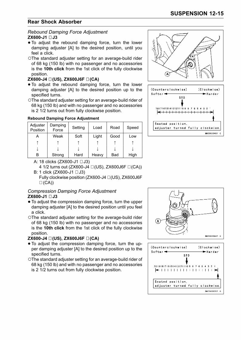
SUSPENSION 12-15Rear Shock Absorber
Rebound Damping Force AdjustmentZX600-J1 ∼ J3•To adjust the rebound damping force, turn the lowerdamping adjuster [A] to the desired position, until youfeel a click.The standard adjuster setting for an average-build riderof 68 kg (150 lb) with no passenger and no accessoriesis the 10th click from the 1st click of the fully clockwiseposition.
ZX600-J4 ∼ (US), ZX600J6F ∼ (CA)•To adjust the rebound damping force, turn the lowerdamping adjuster [A] to the desired position up to thespecified turns.The standard adjuster setting for an average-build rider of68 kg (150 lb) and with no passenger and no accessoriesis 2 1/2 turns out from fully clockwise position.
Rebound Damping Force AdjustmentAdjusterPosition
DampingForce Setting Load Road Speed
A Weak Soft Light Good Low↑ ↑ ↑ ↑ ↑ ↑↓ ↓ ↓ ↓ ↓ ↓B Strong Hard Heavy Bad High
A: 18 clicks (ZX600-J1 ∼ J3)4 1/2 turns out (ZX600-J4 ∼ (US), ZX600J6F ∼ (CA))
B: 1 click (ZX600-J1 ∼ J3)Fully clockwise position (ZX600-J4 ∼ (US), ZX600J6F∼ (CA))
Compression Damping Force AdjustmentZX600-J1 ∼ J3•To adjust the compression damping force, turn the upperdamping adjuster [A] to the desired position until you feela click.The standard adjuster setting for the average-build riderof 68 kg (150 lb) with no passenger and no accessoriesis the 10th click from the 1st click of the fully clockwiseposition.
ZX600-J4 ∼ (US), ZX600J6F ∼ (CA)•To adjust the compression damping force, turn the up-per damping adjuster [A] to the desired position up to thespecified turns.The standard adjuster setting for an average-build rider of68 kg (150 lb) and with no passenger and no accessoriesis 2 1/2 turns out from fully clockwise position.
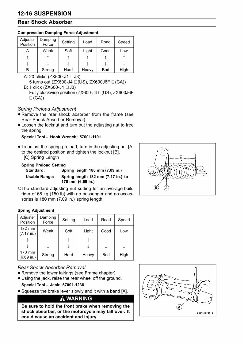
12-16 SUSPENSIONRear Shock Absorber
Compression Damping Force AdjustmentAdjusterPosition
DampingForce Setting Load Road Speed
A Weak Soft Light Good Low↑ ↑ ↑ ↑ ↑ ↑↓ ↓ ↓ ↓ ↓ ↓B Strong Hard Heavy Bad High
A: 20 clicks (ZX600-J1 ∼ J3)5 turns out (ZX600-J4 ∼ (US), ZX600J6F ∼ (CA))
B: 1 click (ZX600-J1 ∼ J3)Fully clockwise position (ZX600-J4 ∼ (US), ZX600J6F∼ (CA))
Spring Preload Adjustment•Remove the rear shock absorber from the frame (seeRear Shock Absorber Removal).• Loosen the locknut and turn out the adjusting nut to freethe spring.Special Tool - Hook Wrench: 57001-1101
•To adjust the spring preload, turn in the adjusting nut [A]to the desired position and tighten the locknut [B].[C] Spring Length
Spring Preload SettingStandard: Spring length 180 mm (7.09 in.)Usable Range: Spring length 182 mm (7.17 in.) to
170 mm (6.69 in.)
The standard adjusting nut setting for an average-buildrider of 68 kg (150 lb) with no passenger and no acces-sories is 180 mm (7.09 in.) spring length.
Spring AdjustmentAdjusterPosition
DampingForce Setting Load Road Speed
182 mm(7.17 in.) Weak Soft Light Good Low
↑ ↑ ↑ ↑ ↑ ↑↓ ↓ ↓ ↓ ↓ ↓
170 mm(6.69 in.) Strong Hard Heavy Bad High
Rear Shock Absorber Removal•Remove the lower fairings (see Frame chapter).• Using the jack, raise the rear wheel off the ground.Special Tool - Jack: 57001-1238
•Squeeze the brake lever slowly and it with a band [A].WARNING
Be sure to hold the front brake when removing theshock absorber, or the motorcycle may fall over. Itcould cause an accident and injury.
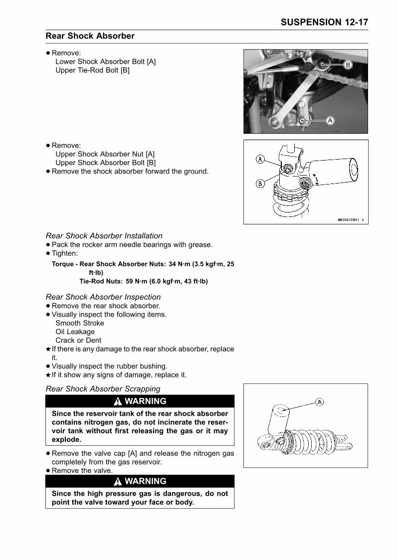
SUSPENSION 12-17Rear Shock Absorber
•Remove:Lower Shock Absorber Bolt [A]Upper Tie-Rod Bolt [B]
•Remove:Upper Shock Absorber Nut [A]Upper Shock Absorber Bolt [B]•Remove the shock absorber forward the ground.
Rear Shock Absorber Installation•Pack the rocker arm needle bearings with grease.• Tighten:Torque - Rear Shock Absorber Nuts: 34 N·m (3.5 kgf·m, 25
ft·lb)Tie-Rod Nuts: 59 N·m (6.0 kgf·m, 43 ft·lb)
Rear Shock Absorber Inspection•Remove the rear shock absorber.• Visually inspect the following items.Smooth StrokeOil LeakageCrack or DentIf there is any damage to the rear shock absorber, replaceit.• Visually inspect the rubber bushing.If it show any signs of damage, replace it.
Rear Shock Absorber ScrappingWARNING
Since the reservoir tank of the rear shock absorbercontains nitrogen gas, do not incinerate the reser-voir tank without first releasing the gas or it mayexplode.
•Remove the valve cap [A] and release the nitrogen gascompletely from the gas reservoir.• Remove the valve.
WARNINGSince the high pressure gas is dangerous, do notpoint the valve toward your face or body.
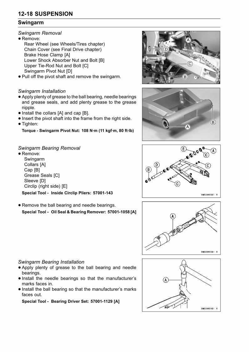
12-18 SUSPENSIONSwingarm
Swingarm Removal•Remove:Rear Wheel (see Wheels/Tires chapter)Chain Cover (see Final Drive chapter)Brake Hose Clamp [A]Lower Shock Absorber Nut and Bolt [B]Upper Tie-Rod Nut and Bolt [C]Swingarm Pivot Nut [D]• Pull off the pivot shaft and remove the swingarm.
Swingarm Installation•Apply plenty of grease to the ball bearing, needle bearingsand grease seals, and add plenty grease to the greasenipple.• Install the collars [A] and cap [B].• Insert the pivot shaft into the frame from the right side.• Tighten:Torque - Swingarm Pivot Nut: 108 N·m (11 kgf·m, 80 ft·lb)
Swingarm Bearing Removal•Remove:SwingarmCollars [A]Cap [B]Grease Seals [C]Sleeve [D]Circlip (right side) [E]Special Tool - Inside Circlip Pliers: 57001-143
•Remove the ball bearing and needle bearings.Special Tool - Oil Seal & Bearing Remover: 57001-1058 [A]
Swingarm Bearing Installation•Apply plenty of grease to the ball bearing and needlebearings.• Install the needle bearings so that the manufacturer’smarks faces in.• Install the ball bearing so that the manufacturer’s marksfaces out.Special Tool - Bearing Driver Set: 57001-1129 [A]
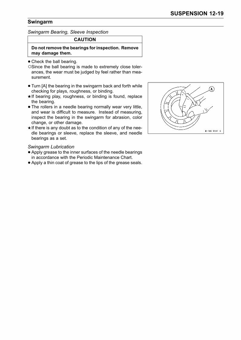
SUSPENSION 12-19Swingarm
Swingarm Bearing, Sleeve InspectionCAUTION
Do not remove the bearings for inspection. Removemay damage them.
•Check the ball bearing.Since the ball bearing is made to extremely close toler-ances, the wear must be judged by feel rather than mea-surement.
• Turn [A] the bearing in the swingarm back and forth whilechecking for plays, roughness, or binding.If bearing play, roughness, or binding is found, replacethe bearing.• The rollers in a needle bearing normally wear very little,and wear is difficult to measure. Instead of measuring,inspect the bearing in the swingarm for abrasion, colorchange, or other damage.If there is any doubt as to the condition of any of the nee-dle bearings or sleeve, replace the sleeve, and needlebearings as a set.
Swingarm Lubrication•Apply grease to the inner surfaces of the needle bearingsin accordance with the Periodic Maintenance Chart.• Apply a thin coat of grease to the lips of the grease seals.
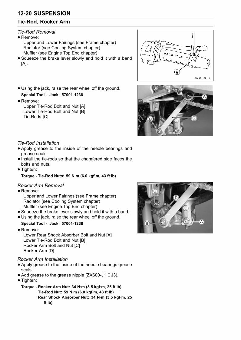
12-20 SUSPENSIONTie-Rod, Rocker Arm
Tie-Rod Removal•Remove:Upper and Lower Fairings (see Frame chapter)Radiator (see Cooling System chapter)Muffler (see Engine Top End chapter)• Squeeze the brake lever slowly and hold it with a band[A].
• Using the jack, raise the rear wheel off the ground.Special Tool - Jack: 57001-1238
•Remove:Upper Tie-Rod Bolt and Nut [A]Lower Tie-Rod Bolt and Nut [B]Tie-Rods [C]
Tie-Rod Installation•Apply grease to the inside of the needle bearings andgrease seals.• Install the tie-rods so that the chamfered side faces thebolts and nuts.• Tighten:Torque - Tie-Rod Nuts: 59 N·m (6.0 kgf·m, 43 ft·lb)
Rocker Arm Removal•Remove:Upper and Lower Fairings (see Frame chapter)Radiator (see Cooling System chapter)Muffler (see Engine Top End chapter)• Squeeze the brake lever slowly and hold it with a band.•Using the jack, raise the rear wheel off the ground.Special Tool - Jack: 57001-1238
•Remove:Lower Rear Shock Absorber Bolt and Nut [A]Lower Tie-Rod Bolt and Nut [B]Rocker Arm Bolt and Nut [C]Rocker Arm [D]
Rocker Arm Installation•Apply grease to the inside of the needle bearings greaseseals.• Add grease to the grease nipple (ZX600-J1 ∼ J3).• Tighten:Torque - Rocker Arm Nut: 34 N·m (3.5 kgf·m, 25 ft·lb)
Tie-Rod Nut: 59 N·m (6.0 kgf·m, 43 ft·lb)Rear Shock Absorber Nut: 34 N·m (3.5 kgf·m, 25ft·lb)
SUSPENSION 12-21Tie-Rod, Rocker Arm
Rocker Arm/Tie-Rod Bearing, Sleeve InspectionCAUTION
Do not remove the bearings for inspection. Removemay damage them.
•Visually inspect the swingarm sleeves and needle bear-ings.• The rollers in a needle bearing normally wear very little,and wear is difficult to measure. Instead of measuring,inspect the bearing for abrasion, color change, or otherdamage.If there is any doubt as to the condition of any of the nee-dle bearings or sleeve, replace the sleeve, and needlebearings as a set.
Rocker Arm/Tie-Rod Lubrication•Apply grease to the inner surfaces of the needle bearingsin accordance with the Periodic Maintenance Chart.• Apply a thin coat of grease to the lips of the grease seals.

STEERING 13-1
13
Steering
Table of ContentsExploded View........................................................................................................................ 13-2Specifications ......................................................................................................................... 13-3Steering .................................................................................................................................. 13-4
Steering Inspection ........................................................................................................... 13-4Steering Adjustment.......................................................................................................... 13-4
Steering Stem......................................................................................................................... 13-5Steering Stem, Stem Bearing Removal ............................................................................ 13-5Steering Stem, Stem Bearing Installation ......................................................................... 13-5Steering Stem Bearing Lubrication ................................................................................... 13-7Steering Stem Warp Inspection ........................................................................................ 13-7
Handlebar ............................................................................................................................... 13-8Handlebar Removal ......................................................................................................... 13-8Handlebar Installation ....................................................................................................... 13-8Handlebar Holder Removal............................................................................................... 13-8Handlebar Holder Installation............................................................................................ 13-9
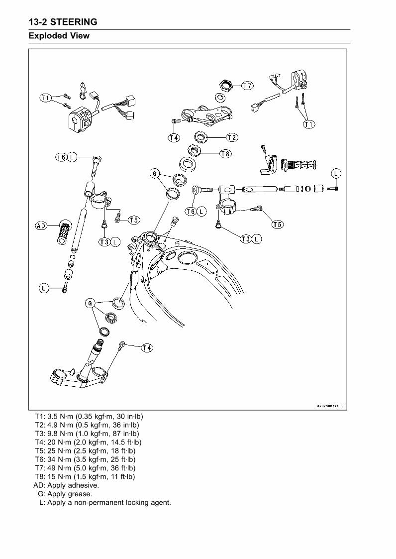
13-2 STEERINGExploded View
T1: 3.5 N·m (0.35 kgf·m, 30 in·lb)T2: 4.9 N·m (0.5 kgf·m, 36 in·lb)T3: 9.8 N·m (1.0 kgf·m, 87 in·lb)T4: 20 N·m (2.0 kgf·m, 14.5 ft·lb)T5: 25 N·m (2.5 kgf·m, 18 ft·lb)T6: 34 N·m (3.5 kgf·m, 25 ft·lb)T7: 49 N·m (5.0 kgf·m, 36 ft·lb)T8: 15 N·m (1.5 kgf·m, 11 ft·lb)AD: Apply adhesive.G: Apply grease.L: Apply a non-permanent locking agent.
STEERING 13-3Specifications
Special Tools - Steering Stem Nut Wrench: 57001-1100Head Pipe Outer Race Press Shaft: 57001-1075Head Pipe Outer Race Driver, 55: 57001-1446Head Pipe Outer Race Driver, 47: 57001-1447Steering Stem Bearing Driver, 42.5: 57001-1344Steering Stem Bearing Driver Adapter, 41.5: 57001-1345Jack: 57001-1238
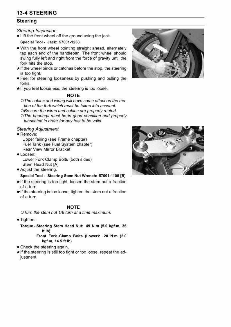
13-4 STEERINGSteering
Steering Inspection• Lift the front wheel off the ground using the jack.Special Tool - Jack: 57001-1238
•With the front wheel pointing straight ahead, alternatelytap each end of the handlebar. The front wheel shouldswing fully left and right from the force of gravity until thefork hits the stop.If the wheel binds or catches before the stop, the steeringis too tight.• Feel for steering looseness by pushing and pulling theforks.If you feel looseness, the steering is too loose.
NOTEThe cables and wiring will have some effect on the mo-tion of the fork which must be taken into account.Be sure the wires and cables are properly routed.The bearings must be in good condition and properlylubricated in order for any test to be valid.
Steering Adjustment•Remove:Upper fairing (see Frame chapter)Fuel Tank (see Fuel System chapter)Rear View Mirror Bracket• Loosen:Lower Fork Clamp Bolts (both sides)Stem Head Nut [A]• Adjust the steering.Special Tool - Steering Stem Nut Wrench: 57001-1100 [B]If the steering is too tight, loosen the stem nut a fractionof a turn.If the steering is too loose, tighten the stem nut a fractionof a turn.
NOTETurn the stem nut 1/8 turn at a time maximum.
•Tighten:Torque - Steering Stem Head Nut: 49 N·m (5.0 kgf·m, 36
ft·lb)Front Fork Clamp Bolts (Lower): 20 N·m (2.0kgf·m, 14.5 ft·lb)
•Check the steering again.If the steering is still too tight or too loose, repeat the ad-justment.
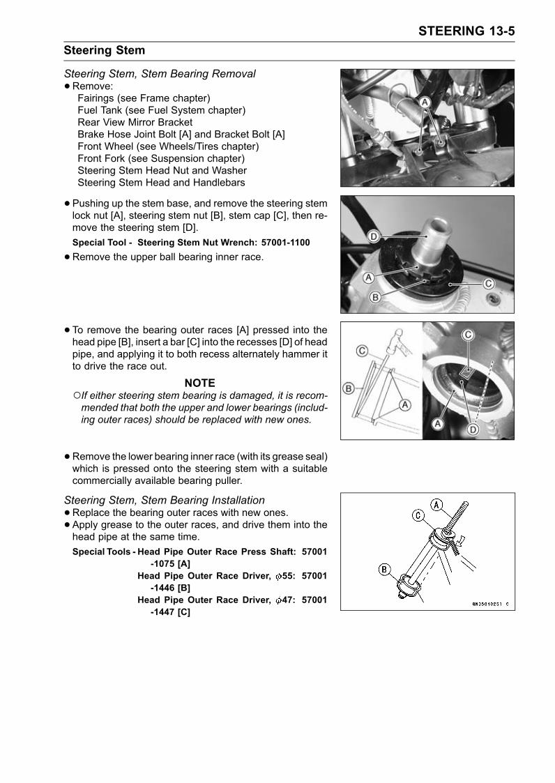
STEERING 13-5Steering Stem
Steering Stem, Stem Bearing Removal•Remove:Fairings (see Frame chapter)Fuel Tank (see Fuel System chapter)Rear View Mirror BracketBrake Hose Joint Bolt [A] and Bracket Bolt [A]Front Wheel (see Wheels/Tires chapter)Front Fork (see Suspension chapter)Steering Stem Head Nut and WasherSteering Stem Head and Handlebars
•Pushing up the stem base, and remove the steering stemlock nut [A], steering stem nut [B], stem cap [C], then re-move the steering stem [D].Special Tool - Steering Stem Nut Wrench: 57001-1100
•Remove the upper ball bearing inner race.
• To remove the bearing outer races [A] pressed into thehead pipe [B], insert a bar [C] into the recesses [D] of headpipe, and applying it to both recess alternately hammer itto drive the race out.
NOTEIf either steering stem bearing is damaged, it is recom-mended that both the upper and lower bearings (includ-ing outer races) should be replaced with new ones.
•Remove the lower bearing inner race (with its grease seal)which is pressed onto the steering stem with a suitablecommercially available bearing puller.
Steering Stem, Stem Bearing Installation•Replace the bearing outer races with new ones.• Apply grease to the outer races, and drive them into thehead pipe at the same time.Special Tools - Head Pipe Outer Race Press Shaft: 57001
-1075 [A]Head Pipe Outer Race Driver, 55: 57001-1446 [B]
Head Pipe Outer Race Driver, 47: 57001-1447 [C]
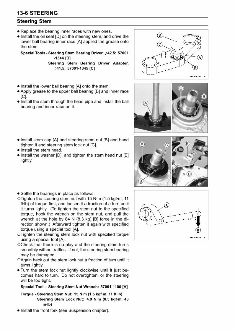
13-6 STEERINGSteering Stem
•Replace the bearing inner races with new ones.• Install the oil seal [D] on the steering stem, and drive thelower ball bearing inner race [A] applied the grease ontothe stem.Special Tools - Steering Stem Bearing Driver, 42.5: 57001
-1344 [B]Steering Stem Bearing Driver Adapter,
41.5: 57001-1345 [C]
• Install the lower ball bearing [A] onto the stem.•Apply grease to the upper ball bearing [B] and inner race[C].• Install the stem through the head pipe and install the ballbearing and inner race on it.
• Install stem cap [A] and steering stem nut [B] and handtighten it and steering stem lock nut [C].• Install the stem head.• Install the washer [D], and tighten the stem head nut [E]lightly.
• Settle the bearings in place as follows:Tighten the steering stem nut with 15 N·m (1.5 kgf·m, 11ft·lb) of torque first, and loosen it a fraction of a turn untilit turns lightly. (To tighten the stem nut to the specifiedtorque, hook the wrench on the stem nut, and pull thewrench at the hole by 84 N (8.3 kg) [B] force in the di-rection shown.) Afterward tighten it again with specifiedtorque using a special tool [A].Tighten the steering stem lock nut with specified torqueusing a special tool [A].Check that there is no play and the steering stem turnssmoothly without rattles. If not, the steering stem bearingmay be damaged.Again back out the stem lock nut a fraction of turn until itturns lightly.• Turn the stem lock nut lightly clockwise until it just be-comes hard to turn. Do not overtighten, or the steeringwill be too tight.Special Tool - Steering Stem Nut Wrench: 57001-1100 [A]
Torque - Steering Stem Nut: 15 N·m (1.5 kgf·m, 11 ft·lb)Steering Stem Lock Nut: 4.9 N·m (0.5 kgf·m, 43in·lb)
• Install the front fork (see Suspension chapter).
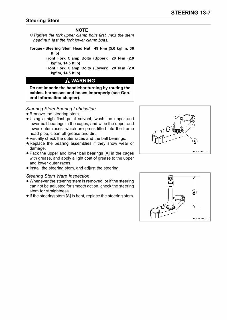
STEERING 13-7Steering Stem
NOTETighten the fork upper clamp bolts first, next the stemhead nut, last the fork lower clamp bolts.
Torque - Steering Stem Head Nut: 49 N·m (5.0 kgf·m, 36ft·lb)
Front Fork Clamp Bolts (Upper): 20 N·m (2.0kgf·m, 14.5 ft·lb)
Front Fork Clamp Bolts (Lower): 20 N·m (2.0kgf·m, 14.5 ft·lb)
WARNINGDo not impede the handlebar turning by routing thecables, harnesses and hoses improperly (see Gen-eral Information chapter).
Steering Stem Bearing Lubrication•Remove the steering stem.•Using a high flash-point solvent, wash the upper andlower ball bearings in the cages, and wipe the upper andlower outer races, which are press-fitted into the framehead pipe, clean off grease and dirt.• Visually check the outer races and the ball bearings.Replace the bearing assemblies if they show wear ordamage.• Pack the upper and lower ball bearings [A] in the cageswith grease, and apply a light coat of grease to the upperand lower outer races.• Install the steering stem, and adjust the steering.Steering Stem Warp Inspection•Whenever the steering stem is removed, or if the steeringcan not be adjusted for smooth action, check the steeringstem for straightness.If the steering stem [A] is bent, replace the steering stem.
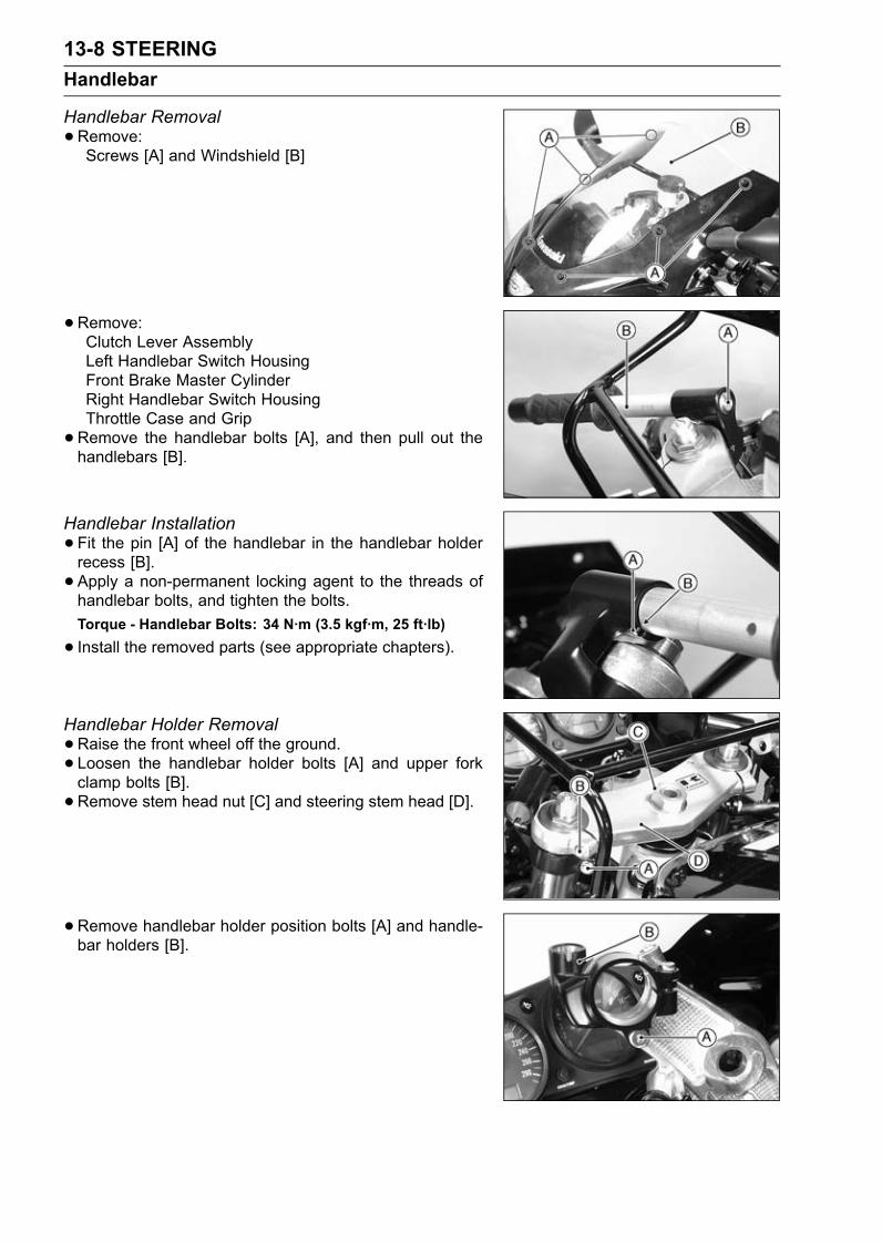
13-8 STEERINGHandlebar
Handlebar Removal•Remove:Screws [A] and Windshield [B]
•Remove:Clutch Lever AssemblyLeft Handlebar Switch HousingFront Brake Master CylinderRight Handlebar Switch HousingThrottle Case and Grip•Remove the handlebar bolts [A], and then pull out thehandlebars [B].
Handlebar Installation•Fit the pin [A] of the handlebar in the handlebar holderrecess [B].• Apply a non-permanent locking agent to the threads ofhandlebar bolts, and tighten the bolts.Torque - Handlebar Bolts: 34 N·m (3.5 kgf·m, 25 ft·lb)
• Install the removed parts (see appropriate chapters).
Handlebar Holder Removal•Raise the front wheel off the ground.• Loosen the handlebar holder bolts [A] and upper forkclamp bolts [B].• Remove stem head nut [C] and steering stem head [D].
• Remove handlebar holder position bolts [A] and handle-bar holders [B].
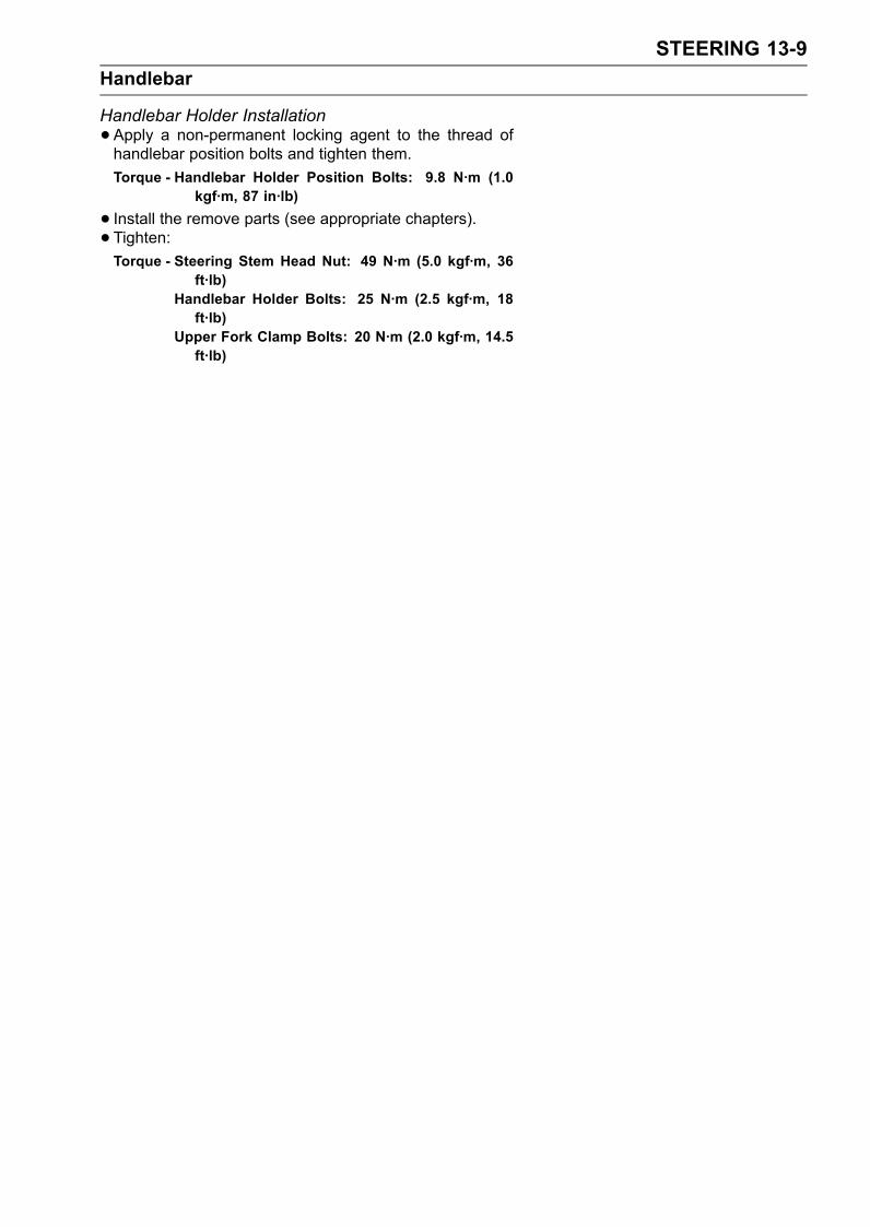
STEERING 13-9Handlebar
Handlebar Holder Installation•Apply a non-permanent locking agent to the thread ofhandlebar position bolts and tighten them.Torque - Handlebar Holder Position Bolts: 9.8 N·m (1.0
kgf·m, 87 in·lb)
• Install the remove parts (see appropriate chapters).• Tighten:Torque - Steering Stem Head Nut: 49 N·m (5.0 kgf·m, 36
ft·lb)Handlebar Holder Bolts: 25 N·m (2.5 kgf·m, 18ft·lb)
Upper Fork Clamp Bolts: 20 N·m (2.0 kgf·m, 14.5ft·lb)

FRAME 14-1
14
FrameTable of Contents
Exploded View........................................................................................................................ 14-2Seats ...................................................................................................................................... 14-5
Rear Seat Removal........................................................................................................... 14-5Rear Seat Installation........................................................................................................ 14-5Front Seat Removal .......................................................................................................... 14-5Front Seat Installation ....................................................................................................... 14-5
Fairings................................................................................................................................... 14-6Lower Fairing Removal ..................................................................................................... 14-6Inner (Upper) Fairing Removal ......................................................................................... 14-6Inner (Lower) Fairing Removal ......................................................................................... 14-6Upper Fairing Removal ..................................................................................................... 14-6
Seat Covers............................................................................................................................ 14-8Seat Cover Removal......................................................................................................... 14-8Seat Cover Installation...................................................................................................... 14-8
Fenders .................................................................................................................................. 14-9Front Fender Removal ...................................................................................................... 14-9Rear Fender Removal....................................................................................................... 14-9
Frame ..................................................................................................................................... 14-10Rear Frame Removal........................................................................................................ 14-10Rear Frame Installation..................................................................................................... 14-10Frame Inspection .............................................................................................................. 14-10
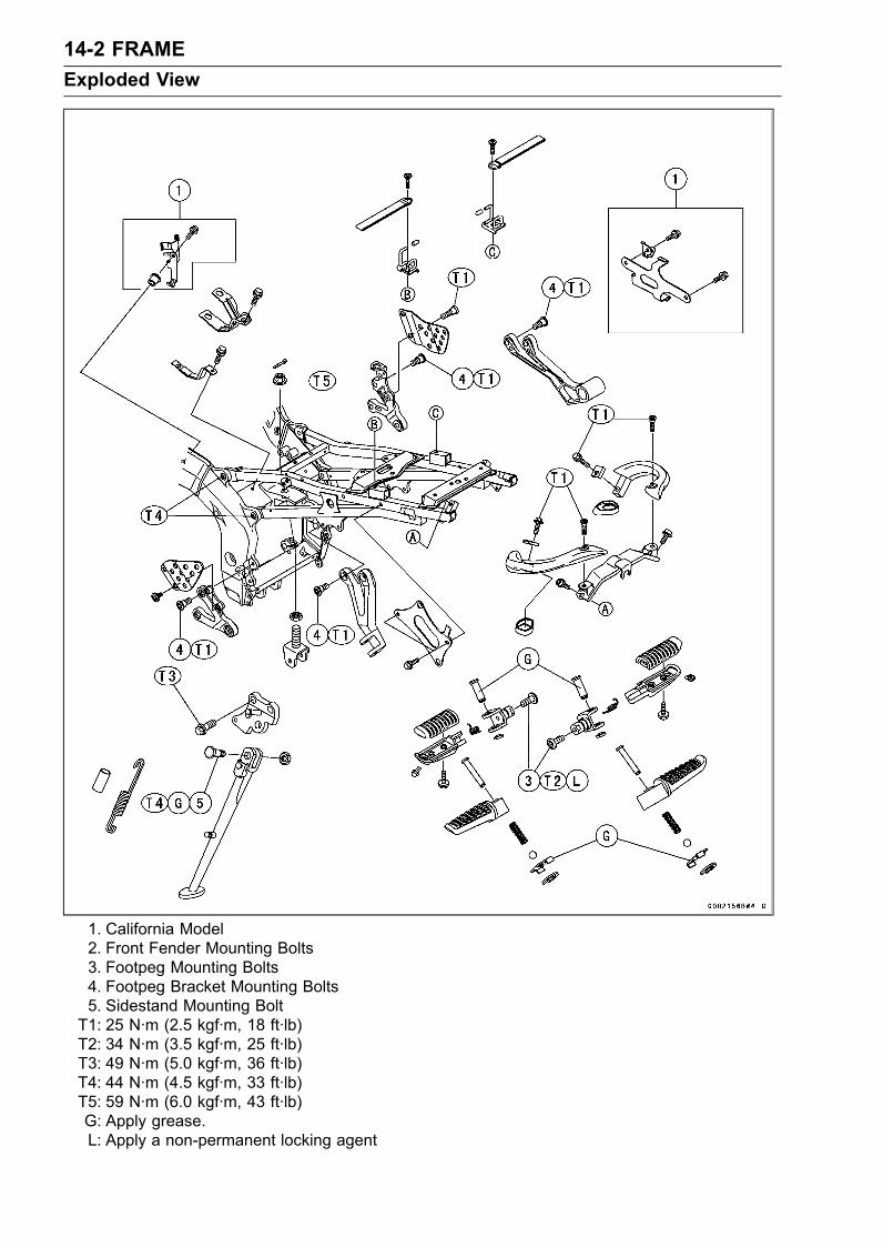
14-2 FRAMEExploded View
1. California Model2. Front Fender Mounting Bolts3. Footpeg Mounting Bolts4. Footpeg Bracket Mounting Bolts5. Sidestand Mounting BoltT1: 25 N·m (2.5 kgf·m, 18 ft·lb)T2: 34 N·m (3.5 kgf·m, 25 ft·lb)T3: 49 N·m (5.0 kgf·m, 36 ft·lb)T4: 44 N·m (4.5 kgf·m, 33 ft·lb)T5: 59 N·m (6.0 kgf·m, 43 ft·lb)G: Apply grease.L: Apply a non-permanent locking agent
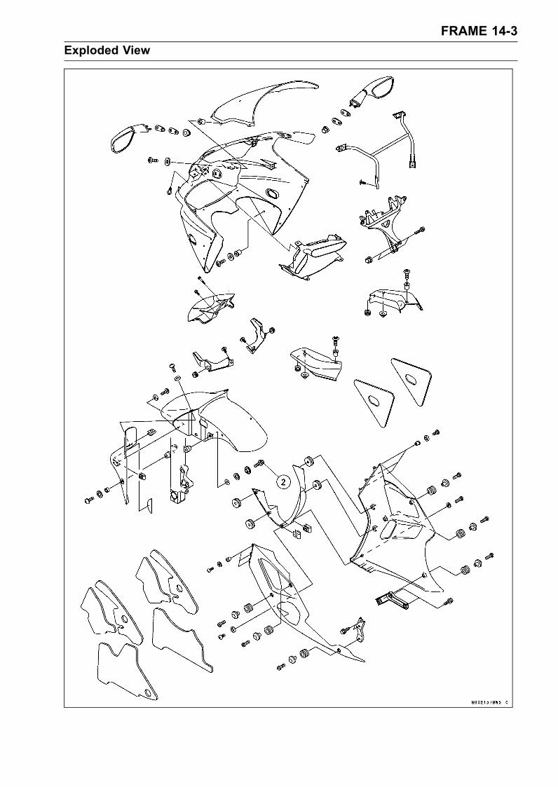
FRAME 14-3Exploded View
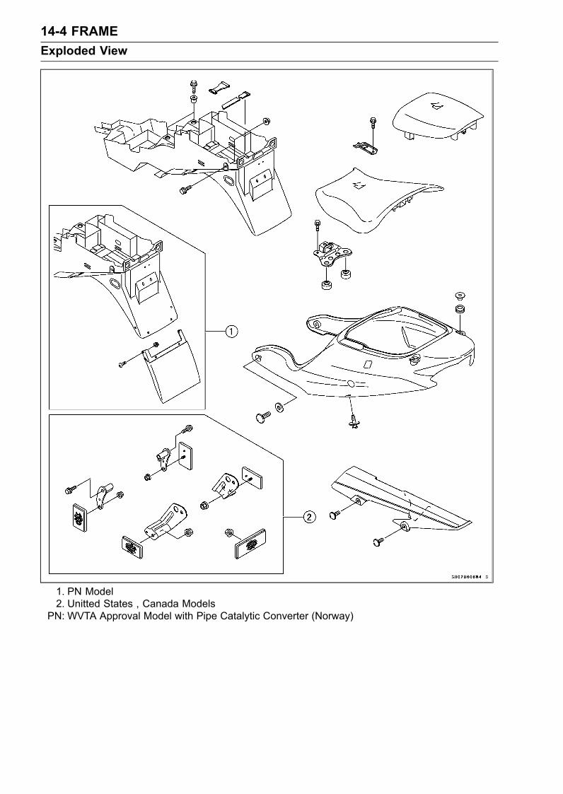
14-4 FRAMEExploded View
1. PN Model2. Unitted States , Canada Models
PN: WVTA Approval Model with Pipe Catalytic Converter (Norway)
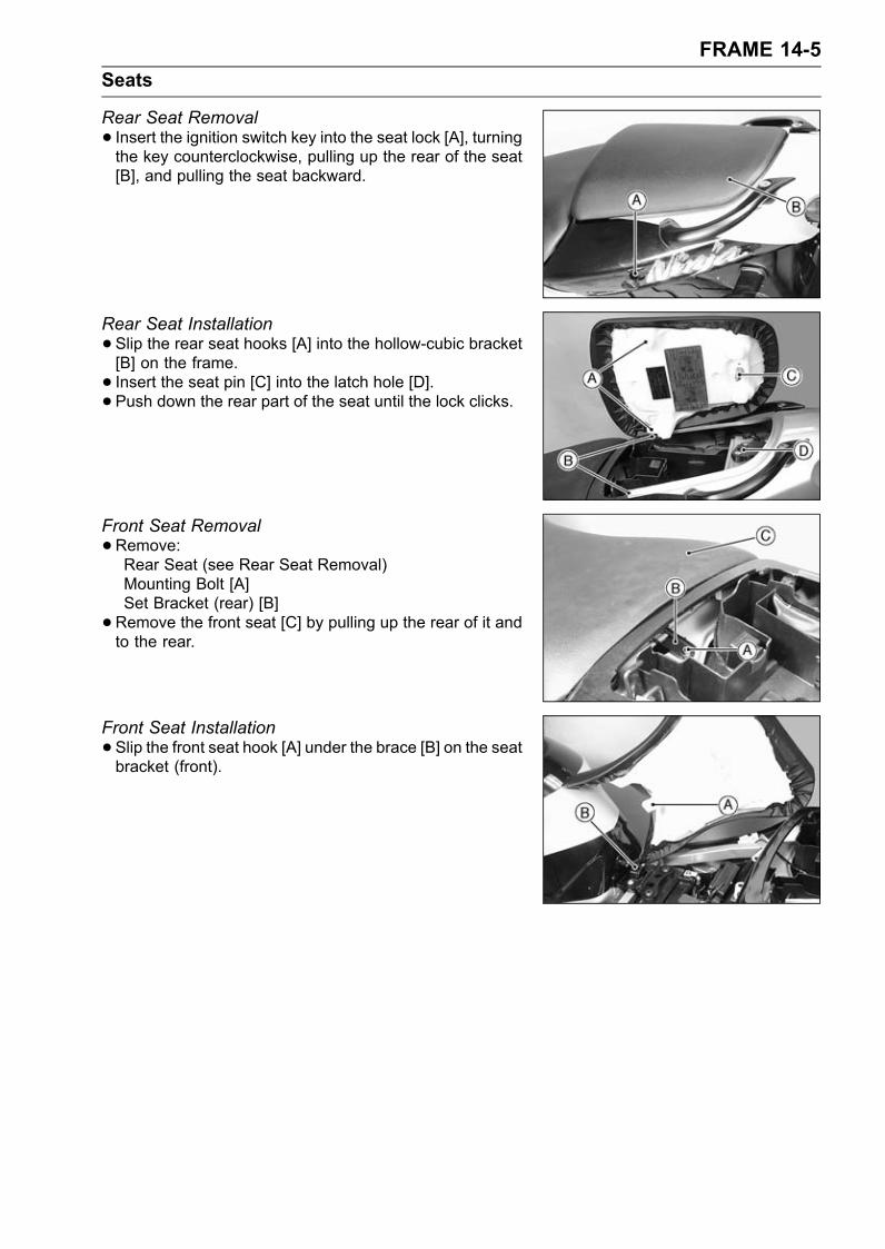
FRAME 14-5Seats
Rear Seat Removal• Insert the ignition switch key into the seat lock [A], turningthe key counterclockwise, pulling up the rear of the seat[B], and pulling the seat backward.
Rear Seat Installation•Slip the rear seat hooks [A] into the hollow-cubic bracket[B] on the frame.• Insert the seat pin [C] into the latch hole [D].• Push down the rear part of the seat until the lock clicks.
Front Seat Removal•Remove:Rear Seat (see Rear Seat Removal)Mounting Bolt [A]Set Bracket (rear) [B]•Remove the front seat [C] by pulling up the rear of it andto the rear.
Front Seat Installation•Slip the front seat hook [A] under the brace [B] on the seatbracket (front).
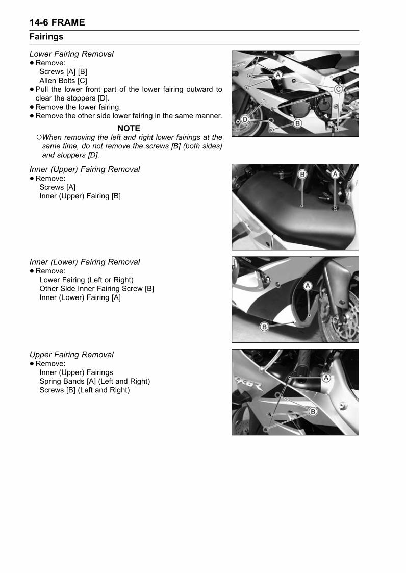
14-6 FRAMEFairings
Lower Fairing Removal•Remove:Screws [A] [B]Allen Bolts [C]• Pull the lower front part of the lower fairing outward toclear the stoppers [D].• Remove the lower fairing.•Remove the other side lower fairing in the same manner.
NOTEWhen removing the left and right lower fairings at thesame time, do not remove the screws [B] (both sides)and stoppers [D].
Inner (Upper) Fairing Removal•Remove:Screws [A]Inner (Upper) Fairing [B]
Inner (Lower) Fairing Removal•Remove:Lower Fairing (Left or Right)Other Side Inner Fairing Screw [B]Inner (Lower) Fairing [A]
Upper Fairing Removal•Remove:Inner (Upper) FairingsSpring Bands [A] (Left and Right)Screws [B] (Left and Right)
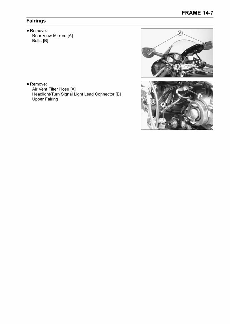
FRAME 14-7Fairings
•Remove:Rear View Mirrors [A]Bolts [B]
•Remove:Air Vent Filter Hose [A]Headlight/Turn Signal Light Lead Connector [B]Upper Fairing
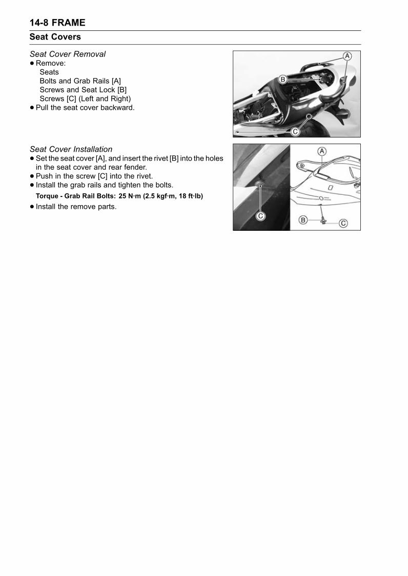
14-8 FRAMESeat Covers
Seat Cover Removal•Remove:SeatsBolts and Grab Rails [A]Screws and Seat Lock [B]Screws [C] (Left and Right)• Pull the seat cover backward.
Seat Cover Installation•Set the seat cover [A], and insert the rivet [B] into the holesin the seat cover and rear fender.• Push in the screw [C] into the rivet.• Install the grab rails and tighten the bolts.Torque - Grab Rail Bolts: 25 N·m (2.5 kgf·m, 18 ft·lb)
• Install the remove parts.
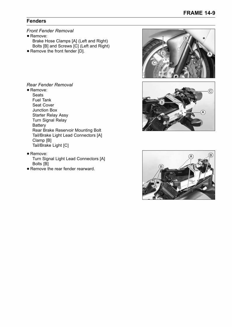
FRAME 14-9Fenders
Front Fender Removal•Remove:Brake Hose Clamps [A] (Left and Right)Bolts [B] and Screws [C] (Left and Right)•Remove the front fender [D].
Rear Fender Removal•Remove:SeatsFuel TankSeat CoverJunction BoxStarter Relay AssyTurn Signal RelayBatteryRear Brake Reservoir Mounting BoltTail/Brake Light Lead Connectors [A]Clamp [B]Tail/Brake Light [C]
•Remove:Turn Signal Light Lead Connectors [A]Bolts [B]•Remove the rear fender rearward.
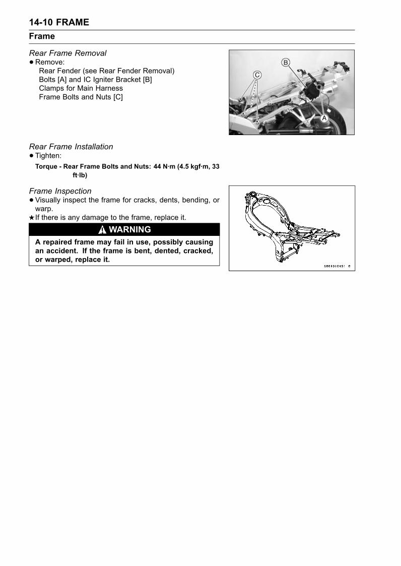
14-10 FRAMEFrame
Rear Frame Removal•Remove:Rear Fender (see Rear Fender Removal)Bolts [A] and IC Igniter Bracket [B]Clamps for Main HarnessFrame Bolts and Nuts [C]
Rear Frame Installation•Tighten:Torque - Rear Frame Bolts and Nuts: 44 N·m (4.5 kgf·m, 33
ft·lb)
Frame Inspection•Visually inspect the frame for cracks, dents, bending, orwarp.If there is any damage to the frame, replace it.
WARNINGA repaired frame may fail in use, possibly causingan accident. If the frame is bent, dented, cracked,or warped, replace it.
ELECTRICAL SYSTEM 15-1
15
Electrical System
Table of ContentsExploded View........................................................................................................................ 15-3Wiring Diagram (United States and Canada) (ZX600-J1 ∼ J2) .............................................. 15-6Wiring Diagram (United States and Canada) (ZX600-J3 ∼ ) ................................................... 15-8Wiring Diagram (Australia) ..................................................................................................... 15-10Wiring Diagram (Other than United States, Canada, Australia, and Malaysia) ...................... 15-12Wiring Diagram (Malaysia) ..................................................................................................... 15-14Specifications ......................................................................................................................... 15-16Parts Location......................................................................................................................... 15-18Precautions............................................................................................................................. 15-19Electrical Wiring...................................................................................................................... 15-21
Wiring Inspection .............................................................................................................. 15-21Battery .................................................................................................................................... 15-22
Battery Removal ............................................................................................................... 15-22Electrolyte Filling............................................................................................................... 15-22Initial Charge..................................................................................................................... 15-23Precautions ....................................................................................................................... 15-23Interchange....................................................................................................................... 15-24Charging Condition Inspection.......................................................................................... 15-24Refreshing Charge............................................................................................................ 15-25
Charging System.................................................................................................................... 15-27Alternator Cover Removal................................................................................................. 15-27Alternator Cover Installation.............................................................................................. 15-27Stator Coil Removal .......................................................................................................... 15-27Stator Coil Installation ....................................................................................................... 15-27Alternator Rotor Removal ................................................................................................. 15-28Alternator Rotor Installation .............................................................................................. 15-28Alternator Inspection ......................................................................................................... 15-29Regulator/Rectifier Inspection........................................................................................... 15-30Charging Voltage Inspection ............................................................................................. 15-32
Ignition System....................................................................................................................... 15-35Crankshaft Sensor Removal ............................................................................................. 15-36Crankshaft Sensor Installation .......................................................................................... 15-37Crankshaft Sensor Inspection........................................................................................... 15-37Crankshaft Sensor Peak Voltage Measurement ............................................................... 15-38Stick Coil (Ignition Coil together with Spark Plug Cap) Removal...................................... 15-38Stick Coil (Ignition Coil together with Spark Plug Cap) Installation................................... 15-38Stick Coil (Ignition Coil together with Spark Plug Cap) Inspection.................................... 15-39Stick Coil Primary Peak Voltage Measurement ................................................................ 15-39Spark Plug Removal ......................................................................................................... 15-40Spark Plug Installation ...................................................................................................... 15-40Spark Plug Cleaning and Inspection................................................................................. 15-40Spark Plug Gap Inspection ............................................................................................... 15-41IC Igniter Inspection .......................................................................................................... 15-41
Electric Starter System........................................................................................................... 15-46Starter Motor Removal...................................................................................................... 15-46Starter Motor Installation................................................................................................... 15-46
15-2 ELECTRICAL SYSTEM
Starter Motor Disassembly................................................................................................ 15-46Starter Motor Assembly .................................................................................................... 15-47Brush Inspection ............................................................................................................... 15-48Commutator Cleaning and Inspection............................................................................... 15-48Armature Inspection.......................................................................................................... 15-49Brush Lead Inspection ...................................................................................................... 15-49Right-hand End Cover Assembly Inspection .................................................................... 15-49Starter Relay Inspection.................................................................................................... 15-49
Lighting System...................................................................................................................... 15-51Headlight Beam Horizontal Adjustment ............................................................................ 15-51Headlight Beam Vertical Adjustment................................................................................. 15-51Headlight Bulb Replacement ............................................................................................ 15-51Headlight Relay Unit Inspection........................................................................................ 15-52Turn Signal Relay Inspection ............................................................................................ 15-54
Fuel Pump .............................................................................................................................. 15-56Fuel Pump Removal/Installation ....................................................................................... 15-56Fuel Pump Relay Internal Resistance Inspection ............................................................. 15-56Fuel Pump Operational Inspection.................................................................................... 15-57
Fuel Cut Valve ........................................................................................................................ 15-59Fuel Cut Valve Removal ................................................................................................... 15-59Fuel Cut Valve Installation ................................................................................................ 15-59Fuel Cut Valve Inspection ................................................................................................. 15-59
Radiator Fan System.............................................................................................................. 15-61Fan System Circuit Inspection .......................................................................................... 15-61Fan Motor Inspection ........................................................................................................ 15-61
Meter, Gauge, Indicator Unit................................................................................................... 15-63Meter Unit Removal .......................................................................................................... 15-63Meter, Gauge Disassembly............................................................................................... 15-63Bulb Replacement............................................................................................................. 15-63Electronic Combination Meter Unit Inspection .................................................................. 15-64
Switches and Sensors............................................................................................................ 15-68Brake Light Timing Inspection........................................................................................... 15-68Brake Light Timing Adjustment ......................................................................................... 15-68Switch Inspection .............................................................................................................. 15-68Radiator Fan Switch Inspection ........................................................................................ 15-69Water Temperature Sensor Inspection ............................................................................. 15-70Throttle Sensor Removal/Installation ................................................................................ 15-70Throttle Sensor Inspection ................................................................................................ 15-70Throttle Sensor Position Adjustment................................................................................. 15-71Speed Sensor Inspection.................................................................................................. 15-72
Junction Box........................................................................................................................... 15-73Junction Box Fuse Circuit Inspection................................................................................ 15-73Starter Circuit/Headlight Relay Inspection ........................................................................ 15-73Diode Circuit Inspection .................................................................................................... 15-74
Fuse........................................................................................................................................ 15-7630 A Main Fuse Removal.................................................................................................. 15-76Junction Box Fuse Removal ............................................................................................. 15-76Fuse Installation................................................................................................................ 15-76Fuse Inspection................................................................................................................. 15-76
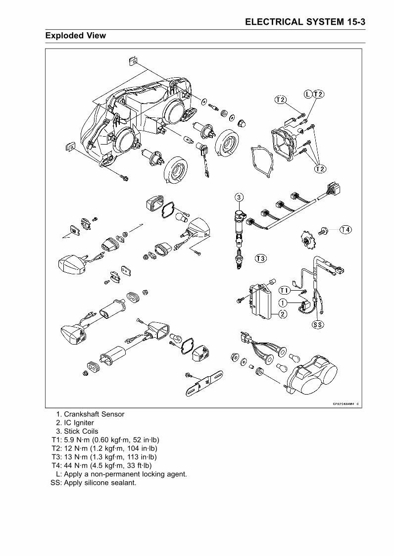
ELECTRICAL SYSTEM 15-3Exploded View
1. Crankshaft Sensor2. IC Igniter3. Stick CoilsT1: 5.9 N·m (0.60 kgf·m, 52 in·lb)T2: 12 N·m (1.2 kgf·m, 104 in·lb)T3: 13 N·m (1.3 kgf·m, 113 in·lb)T4: 44 N·m (4.5 kgf·m, 33 ft·lb)L: Apply a non-permanent locking agent.
SS: Apply silicone sealant.
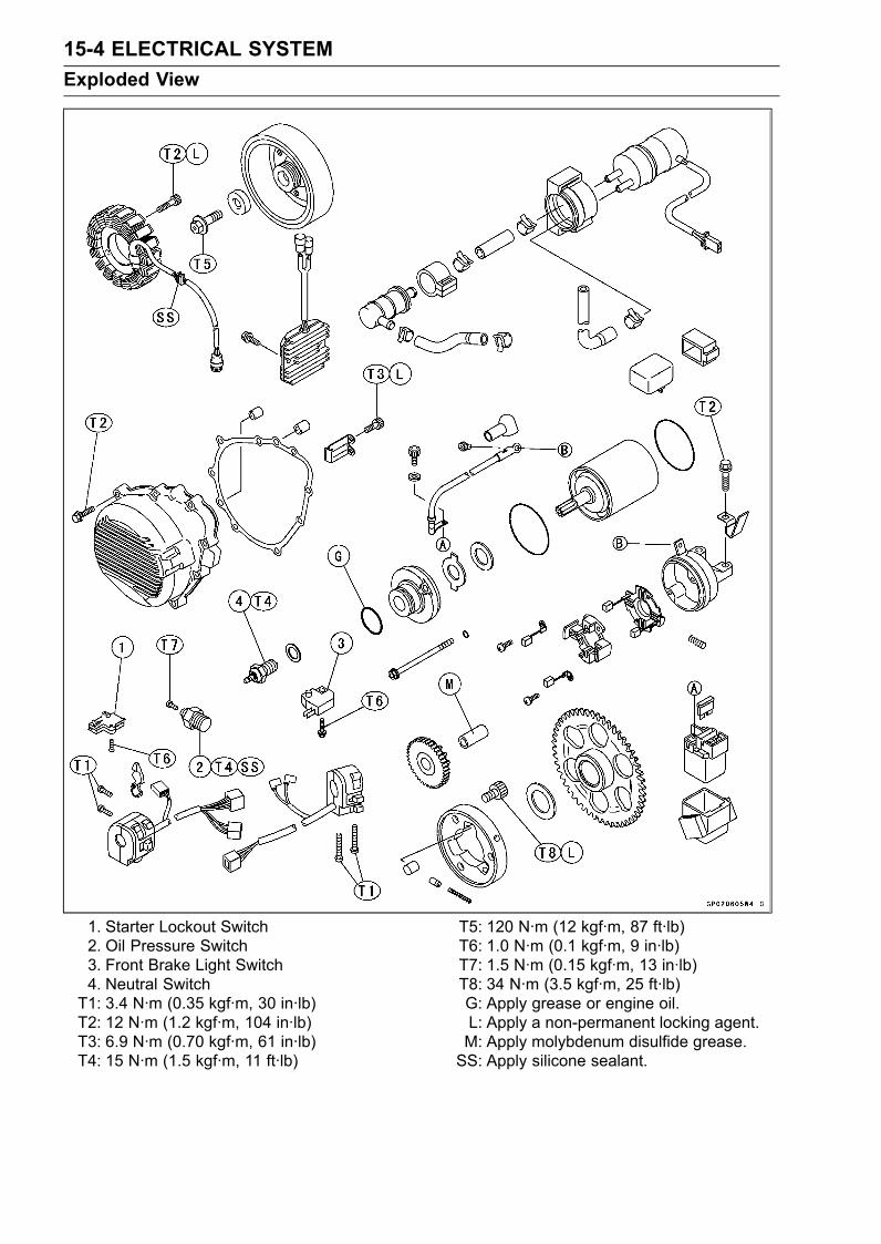
15-4 ELECTRICAL SYSTEMExploded View
1. Starter Lockout Switch2. Oil Pressure Switch3. Front Brake Light Switch4. Neutral SwitchT1: 3.4 N·m (0.35 kgf·m, 30 in·lb)T2: 12 N·m (1.2 kgf·m, 104 in·lb)T3: 6.9 N·m (0.70 kgf·m, 61 in·lb)T4: 15 N·m (1.5 kgf·m, 11 ft·lb)
T5: 120 N·m (12 kgf·m, 87 ft·lb)T6: 1.0 N·m (0.1 kgf·m, 9 in·lb)T7: 1.5 N·m (0.15 kgf·m, 13 in·lb)T8: 34 N·m (3.5 kgf·m, 25 ft·lb)G: Apply grease or engine oil.L: Apply a non-permanent locking agent.M: Apply molybdenum disulfide grease.SS: Apply silicone sealant.
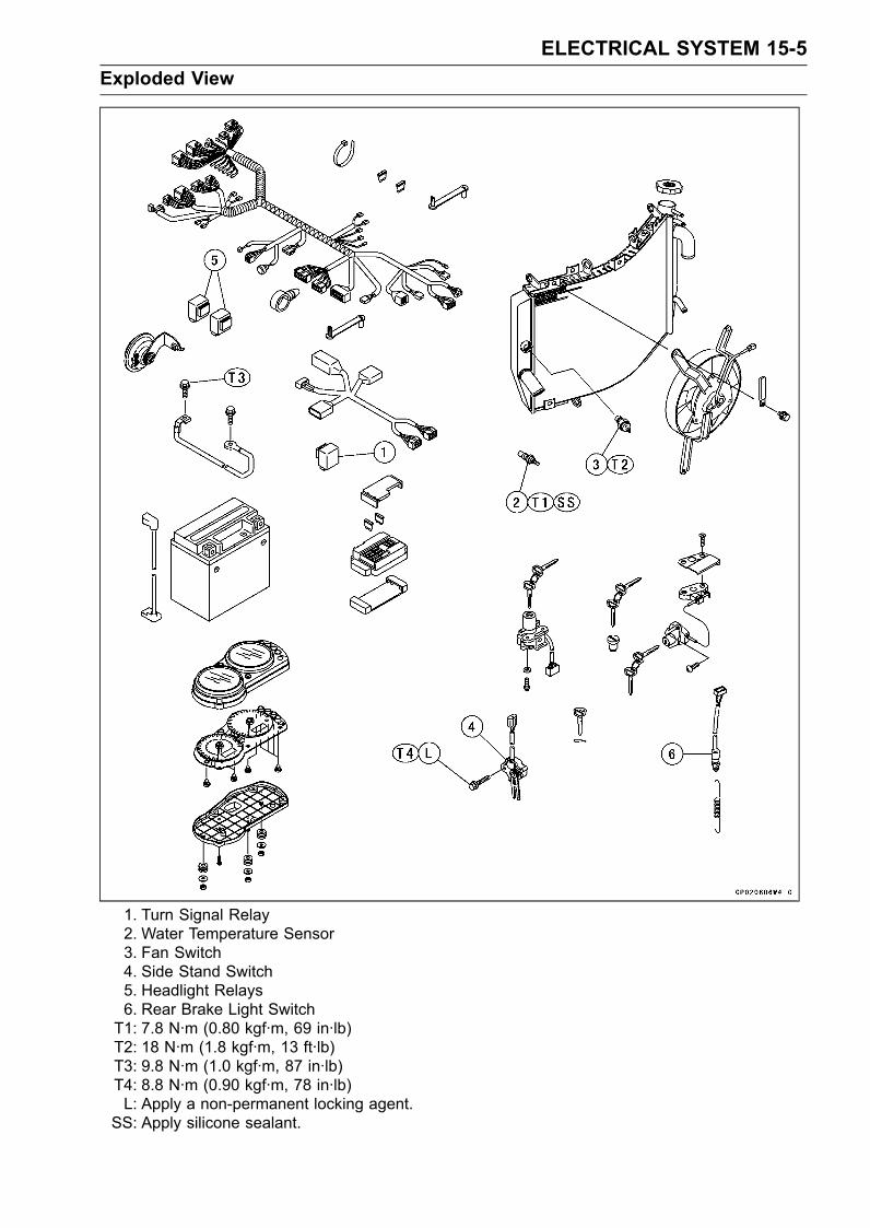
ELECTRICAL SYSTEM 15-5Exploded View
1. Turn Signal Relay2. Water Temperature Sensor3. Fan Switch4. Side Stand Switch5. Headlight Relays6. Rear Brake Light SwitchT1: 7.8 N·m (0.80 kgf·m, 69 in·lb)T2: 18 N·m (1.8 kgf·m, 13 ft·lb)T3: 9.8 N·m (1.0 kgf·m, 87 in·lb)T4: 8.8 N·m (0.90 kgf·m, 78 in·lb)L: Apply a non-permanent locking agent.
SS: Apply silicone sealant.
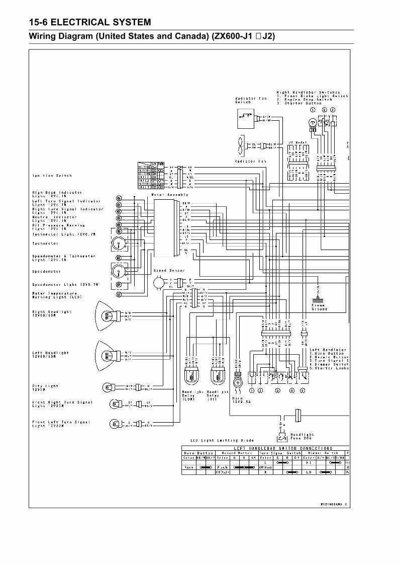
15-6 ELECTRICAL SYSTEMWiring Diagram (United States and Canada) (ZX600-J1 ∼ J2)
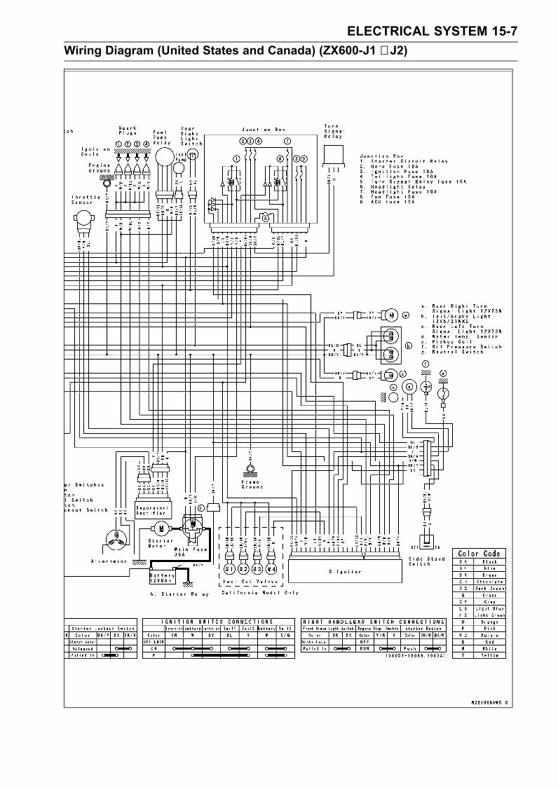
ELECTRICAL SYSTEM 15-7Wiring Diagram (United States and Canada) (ZX600-J1 ∼ J2)
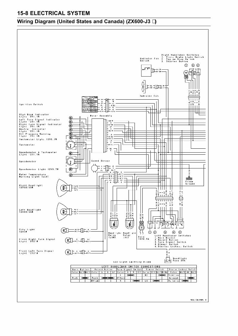
15-8 ELECTRICAL SYSTEMWiring Diagram (United States and Canada) (ZX600-J3 ∼ )
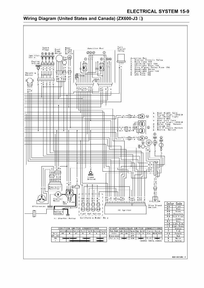
ELECTRICAL SYSTEM 15-9Wiring Diagram (United States and Canada) (ZX600-J3 ∼ )
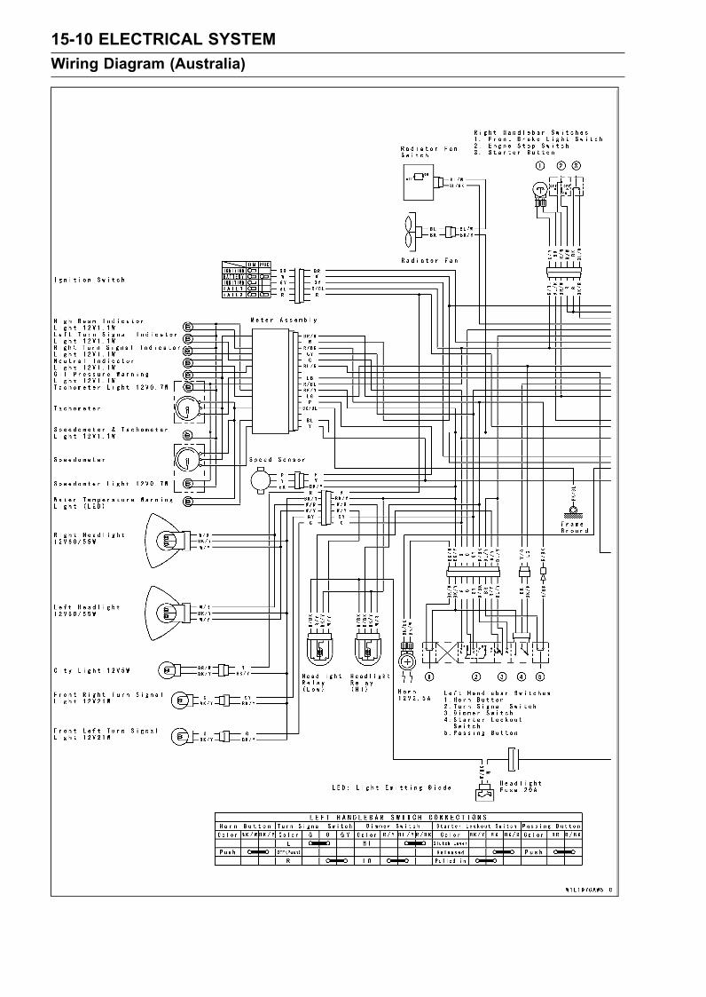
15-10 ELECTRICAL SYSTEMWiring Diagram (Australia)
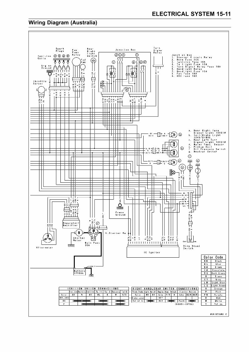
ELECTRICAL SYSTEM 15-11Wiring Diagram (Australia)
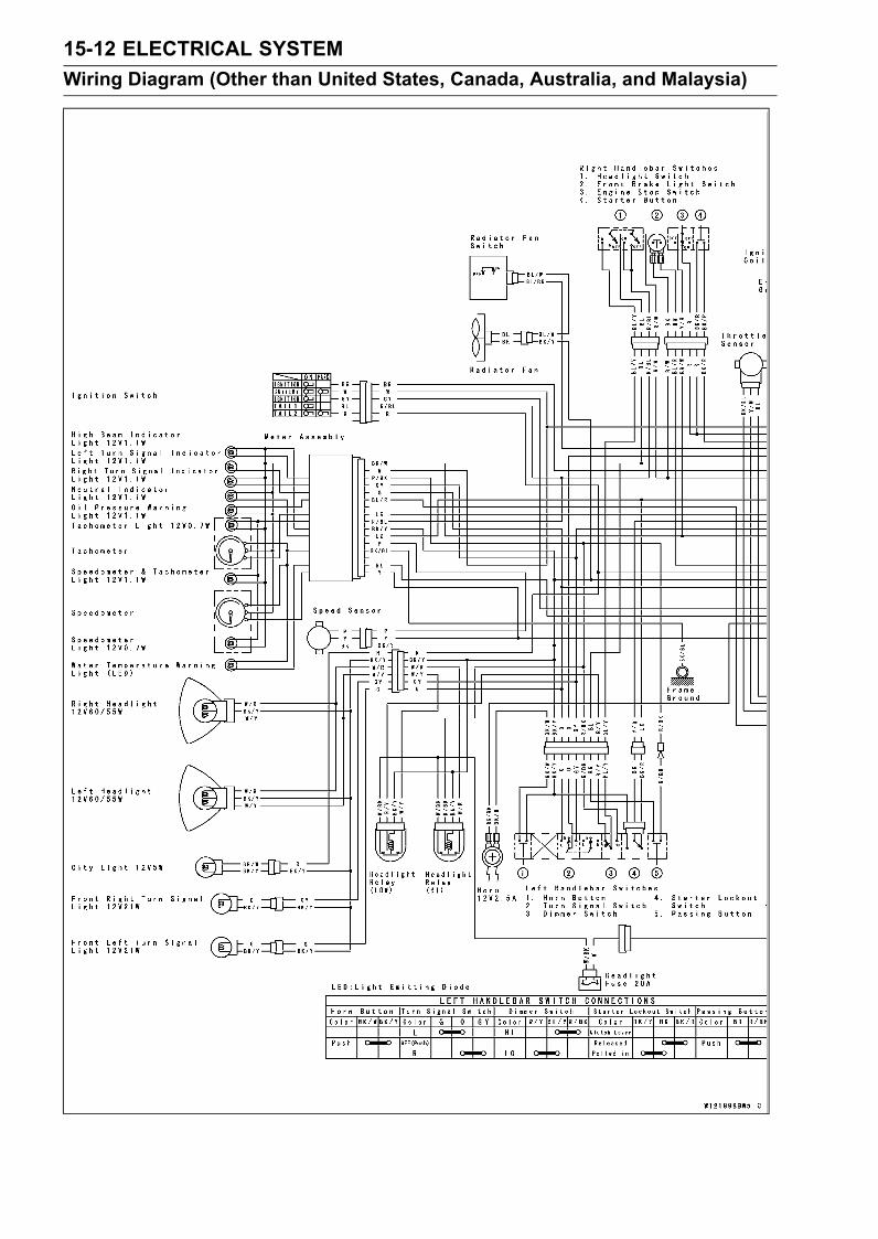
15-12 ELECTRICAL SYSTEMWiring Diagram (Other than United States, Canada, Australia, and Malaysia)
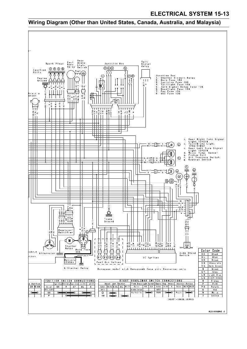
ELECTRICAL SYSTEM 15-13Wiring Diagram (Other than United States, Canada, Australia, and Malaysia)
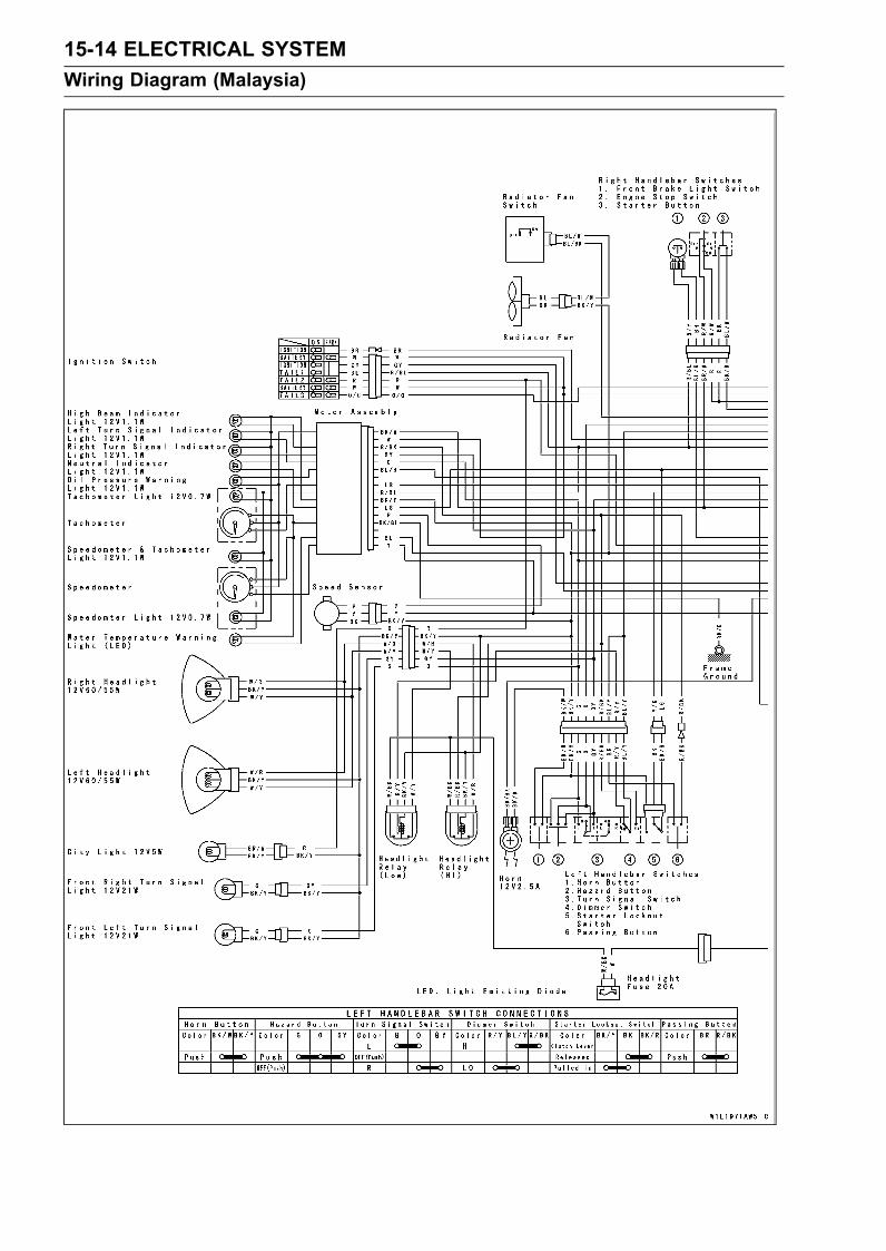
15-14 ELECTRICAL SYSTEMWiring Diagram (Malaysia)
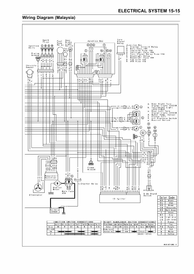
ELECTRICAL SYSTEM 15-15Wiring Diagram (Malaysia)
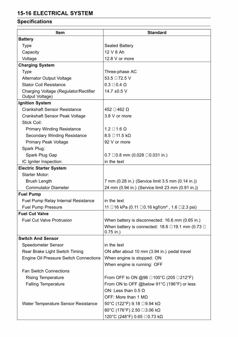
15-16 ELECTRICAL SYSTEMSpecifications
Item StandardBatteryType Sealed BatteryCapacity 12 V 8 AhVoltage 12.8 V or more
Charging SystemType Three-phase ACAlternator Output Voltage 53.5 ∼ 72.5 VStator Coil Resistance 0.3 ∼ 0.4 ΩCharging Voltage (Regulator/RectifierOutput Voltage)
14.7 ±0.5 V
Ignition SystemCrankshaft Sensor Resistance 452 ∼ 462 ΩCrankshaft Sensor Peak Voltage 3.8 V or moreStick Coil:Primary Winding Resistance 1.2 ∼ 1.6 ΩSecondary Winding Resistance 8.5 ∼ 11.5 kΩPrimary Peak Voltage 92 V or more
Spark Plug:Spark Plug Gap 0.7 ∼ 0.8 mm (0.028 ∼ 0.031 in.)
IC Igniter Inspection: in the textElectric Starter SystemStarter Motor:Brush Length 7 mm (0.28 in.) (Service limit 3.5 mm (0.14 in.))Commutator Diameter 24 mm (0.94 in.) (Service limit 23 mm (0.91 in.))
Fuel PumpFuel Pump Relay Internal Resistance in the textFuel Pump Pressure 11 ∼ 16 kPa (0.11 ∼ 0.16 kgf/cm² , 1.6 ∼ 2.3 psi)
Fuel Cut ValveFuel Cut Valve Protrusion When battery is disconnected: 16.6 mm (0.65 in.)
When battery is connected: 18.6 ∼ 19.1 mm (0.73 ∼0.75 in.)
Switch And SensorSpeedometer Sensor in the textRear Brake Light Switch Timing ON after about 10 mm (3.94 in.) pedal travelEngine Oil Pressure Switch Connections When engine is stopped: ON
When engine is running: OFFFan Switch ConnectionsRising Temperature From OFF to ON @96 ∼ 100°C (205 ∼ 212°F)Falling Temperature From ON to OFF @below 91°C (196°F) or less
ON: Less than 0.5 ΩOFF: More than 1 MΩ
Water Temperature Sensor Resistance 50°C (122°F) 9.18 ∼ 9.94 kΩ80°C (176°F) 2.50 ∼ 3.06 kΩ120°C (248°F) 0.65 ∼ 0.73 kΩ
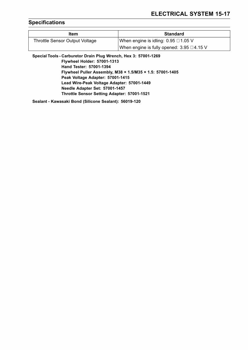
ELECTRICAL SYSTEM 15-17Specifications
Item StandardThrottle Sensor Output Voltage When engine is idling: 0.95 ∼ 1.05 V
When engine is fully opened: 3.95 ∼ 4.15 V
Special Tools - Carburetor Drain Plug Wrench, Hex 3: 57001-1269Flywheel Holder: 57001-1313Hand Tester: 57001-1394Flywheel Puller Assembly, M38 × 1.5/M35 × 1.5: 57001-1405Peak Voltage Adapter: 57001-1415Lead Wire-Peak Voltage Adapter: 57001-1449Needle Adapter Set: 57001-1457Throttle Sensor Setting Adapter: 57001-1521
Sealant - Kawasaki Bond (Silicone Sealant): 56019-120
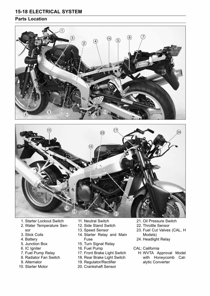
15-18 ELECTRICAL SYSTEMParts Location
1. Starter Lockout Switch2. Water Temperature Sen-sor
3. Stick Coils4. Battery5. Junction Box6. IC Igniter7. Fuel Pump Relay8. Radiator Fan Switch9. Alternator10. Starter Motor
11. Neutral Switch12. Side Stand Switch13. Speed Sensor14. Starter Relay and Main
Fuse15. Turn Signal Relay16. Fuel Pump17. Front Brake Light Switch18. Rear Brake Light Switch19. Regulator/Rectifier20. Crankshaft Sensor
21. Oil Pressure Switch22. Throttle Sensor23. Fuel Cut Valves (CAL, H
Models)24. Headlight Relay
CAL: CaliforniaH: WVTA Approval Modelwith Honeycomb Cat-alytic Converter
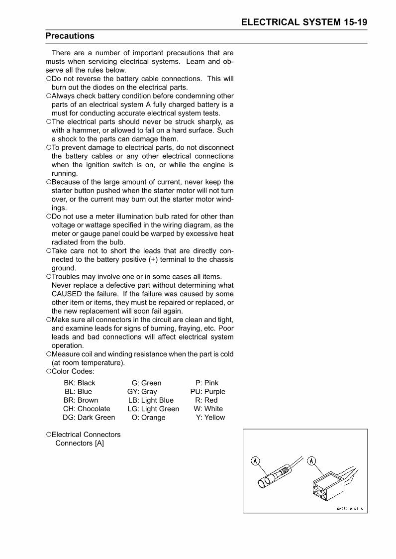
ELECTRICAL SYSTEM 15-19Precautions
There are a number of important precautions that aremusts when servicing electrical systems. Learn and ob-serve all the rules below.Do not reverse the battery cable connections. This willburn out the diodes on the electrical parts.Always check battery condition before condemning otherparts of an electrical system A fully charged battery is amust for conducting accurate electrical system tests.The electrical parts should never be struck sharply, aswith a hammer, or allowed to fall on a hard surface. Sucha shock to the parts can damage them.To prevent damage to electrical parts, do not disconnectthe battery cables or any other electrical connectionswhen the ignition switch is on, or while the engine isrunning.Because of the large amount of current, never keep thestarter button pushed when the starter motor will not turnover, or the current may burn out the starter motor wind-ings.Do not use a meter illumination bulb rated for other thanvoltage or wattage specified in the wiring diagram, as themeter or gauge panel could be warped by excessive heatradiated from the bulb.Take care not to short the leads that are directly con-nected to the battery positive (+) terminal to the chassisground.Troubles may involve one or in some cases all items.Never replace a defective part without determining whatCAUSED the failure. If the failure was caused by someother item or items, they must be repaired or replaced, orthe new replacement will soon fail again.Make sure all connectors in the circuit are clean and tight,and examine leads for signs of burning, fraying, etc. Poorleads and bad connections will affect electrical systemoperation.Measure coil and winding resistance when the part is cold(at room temperature).Color Codes:
BK: BlackBL: BlueBR: BrownCH: ChocolateDG: Dark Green
G: GreenGY: GrayLB: Light BlueLG: Light GreenO: Orange
P: PinkPU: PurpleR: RedW: WhiteY: Yellow
Electrical ConnectorsConnectors [A]
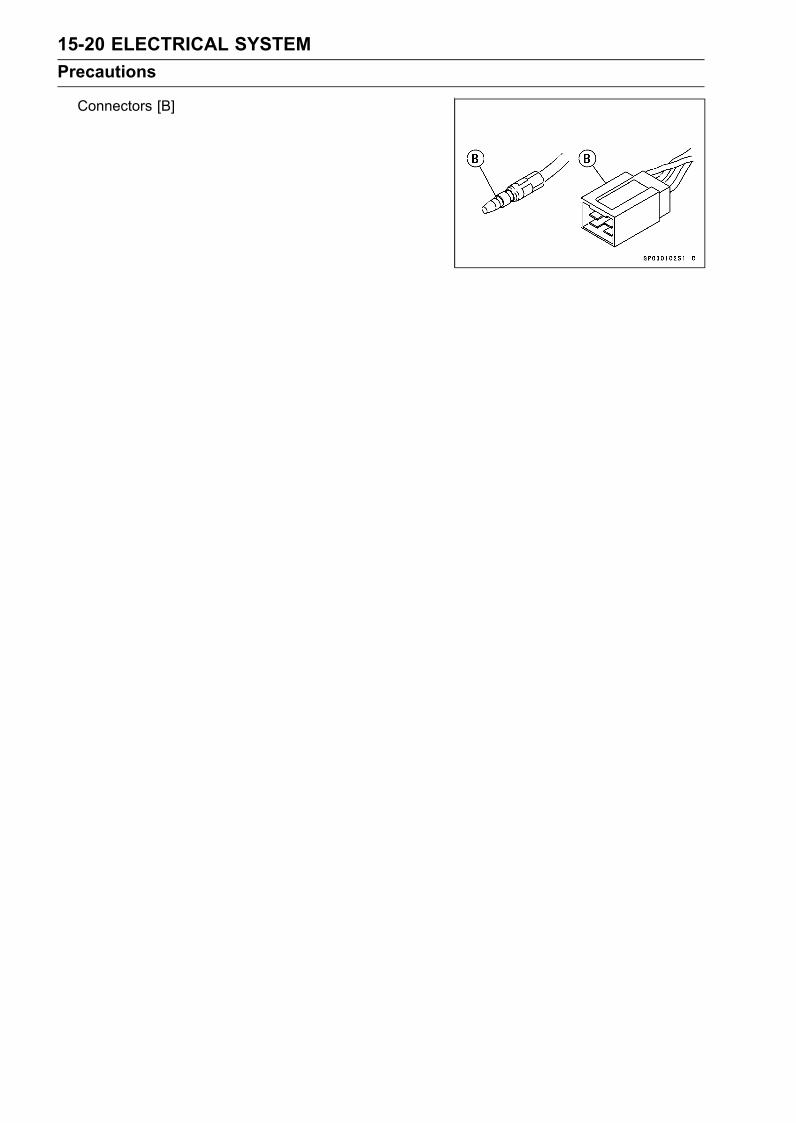
15-20 ELECTRICAL SYSTEMPrecautions
Connectors [B]
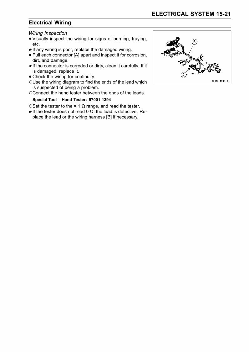
ELECTRICAL SYSTEM 15-21Electrical Wiring
Wiring Inspection•Visually inspect the wiring for signs of burning, fraying,etc.If any wiring is poor, replace the damaged wiring.• Pull each connector [A] apart and inspect it for corrosion,dirt, and damage.If the connector is corroded or dirty, clean it carefully. If itis damaged, replace it.• Check the wiring for continuity.Use the wiring diagram to find the ends of the lead whichis suspected of being a problem.Connect the hand tester between the ends of the leads.Special Tool - Hand Tester: 57001-1394Set the tester to the × 1 Ω range, and read the tester.If the tester does not read 0 Ω, the lead is defective. Re-place the lead or the wiring harness [B] if necessary.
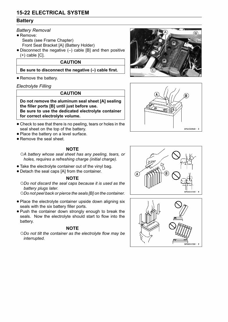
15-22 ELECTRICAL SYSTEMBattery
Battery Removal•Remove:Seats (see Frame Chapter)Front Seat Bracket [A] (Battery Holder)•Disconnect the negative (–) cable [B] and then positive(+) cable [C].
CAUTIONBe sure to disconnect the negative (–) cable first.
•Remove the battery.Electrolyte Filling
CAUTIONDo not remove the aluminum seal sheet [A] sealingthe filler ports [B] until just before use.Be sure to use the dedicated electrolyte containerfor correct electrolyte volume.
•Check to see that there is no peeling, tears or holes in theseal sheet on the top of the battery.• Place the battery on a level surface.•Remove the seal sheet.
NOTEA battery whose seal sheet has any peeling, tears, orholes, requires a refreshing charge (initial charge).
•Take the electrolyte container out of the vinyl bag.•Detach the seal caps [A] from the container.
NOTEDo not discard the seal caps because it is used as thebattery plugs later.Do not peel back or pierce the seals [B] on the container.•Place the electrolyte container upside down aligning sixseals with the six battery filler ports.• Push the container down strongly enough to break theseals. Now the electrolyte should start to flow into thebattery.
NOTEDo not tilt the container as the electrolyte flow may beinterrupted.
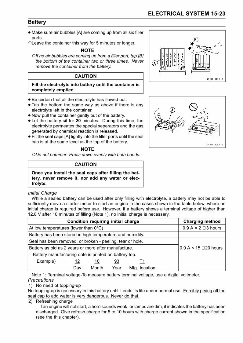
ELECTRICAL SYSTEM 15-23Battery
•Make sure air bubbles [A] are coming up from all six fillerports.Leave the container this way for 5 minutes or longer.
NOTEIf no air bubbles are coming up from a filler port, tap [B]the bottom of the container two or three times. Neverremove the container from the battery.
CAUTIONFill the electrolyte into battery until the container iscompletely emptied.
•Be certain that all the electrolyte has flowed out.• Tap the bottom the same way as above if there is anyelectrolyte left in the container.• Now pull the container gently out of the battery.• Let the battery sit for 20 minutes. During this time, theelectrolyte permeates the special separators and the gasgenerated by chemical reaction is released.• Fit the seal caps [A] tightly into the filler ports until the sealcap is at the same level as the top of the battery.
NOTEDo not hammer. Press down evenly with both hands.
CAUTIONOnce you install the seal caps after filling the bat-tery, never remove it, nor add any water or elec-trolyte.
Initial ChargeWhile a sealed battery can be used after only filling with electrolyte, a battery may not be able to
sufficiently move a starter motor to start an engine in the cases shown in the table below, where aninitial charge is required before use. However, if a battery shows a terminal voltage of higher than12.8 V after 10 minutes of filling (Note 1), no initial charge is necessary.
Condition requiring initial charge Charging methodAt low temperatures (lower than 0°C) 0.9 A × 2 ∼ 3 hoursBattery has been stored in high temperature and humidity.Seal has been removed, or broken - peeling, tear or hole.Battery as old as 2 years or more after manufacture. 0.9 A × 15 ∼ 20 hoursBattery manufacturing date is printed on battery top.Example) 12 10 93 T1
Day Month Year Mfg. locationNote 1: Terminal voltage-To measure battery terminal voltage, use a digital voltmeter.
Precautions1) No need of topping-upNo topping-up is necessary in this battery until it ends its life under normal use. Forcibly prying off theseal cap to add water is very dangerous. Never do that.2) Refreshing charge
If an engine will not start, a horn sounds weak, or lamps are dim, it indicates the battery has beendischarged. Give refresh charge for 5 to 10 hours with charge current shown in the specification(see the this chapter).
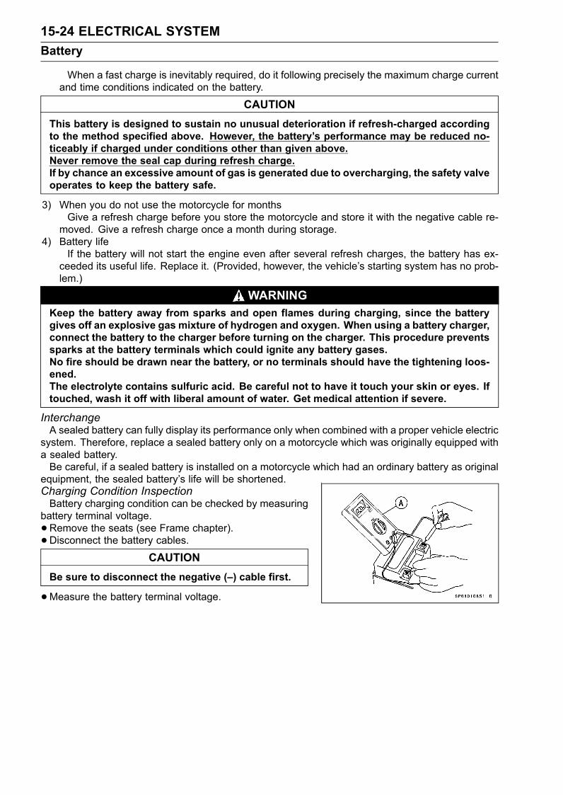
15-24 ELECTRICAL SYSTEMBattery
When a fast charge is inevitably required, do it following precisely the maximum charge currentand time conditions indicated on the battery.
CAUTIONThis battery is designed to sustain no unusual deterioration if refresh-charged accordingto the method specified above. However, the battery’s performance may be reduced no-ticeably if charged under conditions other than given above.Never remove the seal cap during refresh charge.If by chance an excessive amount of gas is generated due to overcharging, the safety valveoperates to keep the battery safe.
3) When you do not use the motorcycle for monthsGive a refresh charge before you store the motorcycle and store it with the negative cable re-
moved. Give a refresh charge once a month during storage.4) Battery life
If the battery will not start the engine even after several refresh charges, the battery has ex-ceeded its useful life. Replace it. (Provided, however, the vehicle’s starting system has no prob-lem.)
WARNINGKeep the battery away from sparks and open flames during charging, since the batterygives off an explosive gas mixture of hydrogen and oxygen. When using a battery charger,connect the battery to the charger before turning on the charger. This procedure preventssparks at the battery terminals which could ignite any battery gases.No fire should be drawn near the battery, or no terminals should have the tightening loos-ened.The electrolyte contains sulfuric acid. Be careful not to have it touch your skin or eyes. Iftouched, wash it off with liberal amount of water. Get medical attention if severe.
InterchangeA sealed battery can fully display its performance only when combined with a proper vehicle electric
system. Therefore, replace a sealed battery only on a motorcycle which was originally equipped witha sealed battery.Be careful, if a sealed battery is installed on a motorcycle which had an ordinary battery as original
equipment, the sealed battery’s life will be shortened.Charging Condition InspectionBattery charging condition can be checked by measuring
battery terminal voltage.•Remove the seats (see Frame chapter).• Disconnect the battery cables.
CAUTIONBe sure to disconnect the negative (–) cable first.
•Measure the battery terminal voltage.
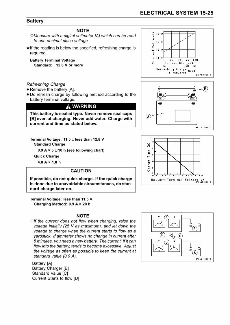
ELECTRICAL SYSTEM 15-25Battery
NOTEMeasure with a digital voltmeter [A] which can be readto one decimal place voltage.
If the reading is below the specified, refreshing charge isrequired.
Battery Terminal VoltageStandard: 12.8 V or more
Refreshing Charge•Remove the battery [A].• Do refresh-charge by following method according to thebattery terminal voltage.
WARNINGThis battery is sealed type. Never remove seal caps[B] even at charging. Never add water. Charge withcurrent and time as stated below.
Terminal Voltage: 11.5 ∼ less than 12.8 VStandard Charge0.9 A × 5 ∼ 10 h (see following chart)
Quick Charge4.0 A × 1.0 h
CAUTIONIf possible, do not quick charge. If the quick chargeis done due to unavoidable circumstances, do stan-dard charge later on.
Terminal Voltage: less than 11.5 VCharging Method: 0.9 A × 20 h
NOTEIf the current does not flow when charging, raise thevoltage initially (25 V as maximum), and let down thevoltage to charge when the current starts to flow as ayardstick. If ammeter shows no change in current after5 minutes, you need a new battery. The current, if it canflow into the battery, tends to become excessive. Adjustthe voltage as often as possible to keep the current atstandard value (0.9 A).
Battery [A]Battery Charger [B]Standard Value [C]Current Starts to flow [D]

15-26 ELECTRICAL SYSTEMBattery
•Determine battery condition after refreshing charge.Determine the condition of the battery 30 minutes aftercompletion of the charge by measuring the terminal volt-age according to the table below.
Criteria Judgement12.8 V or higher Good12.0 ∼ 12.8 V or lower Charge insufficient → Recharge.12.0 V or lower Unserviceable → Replace
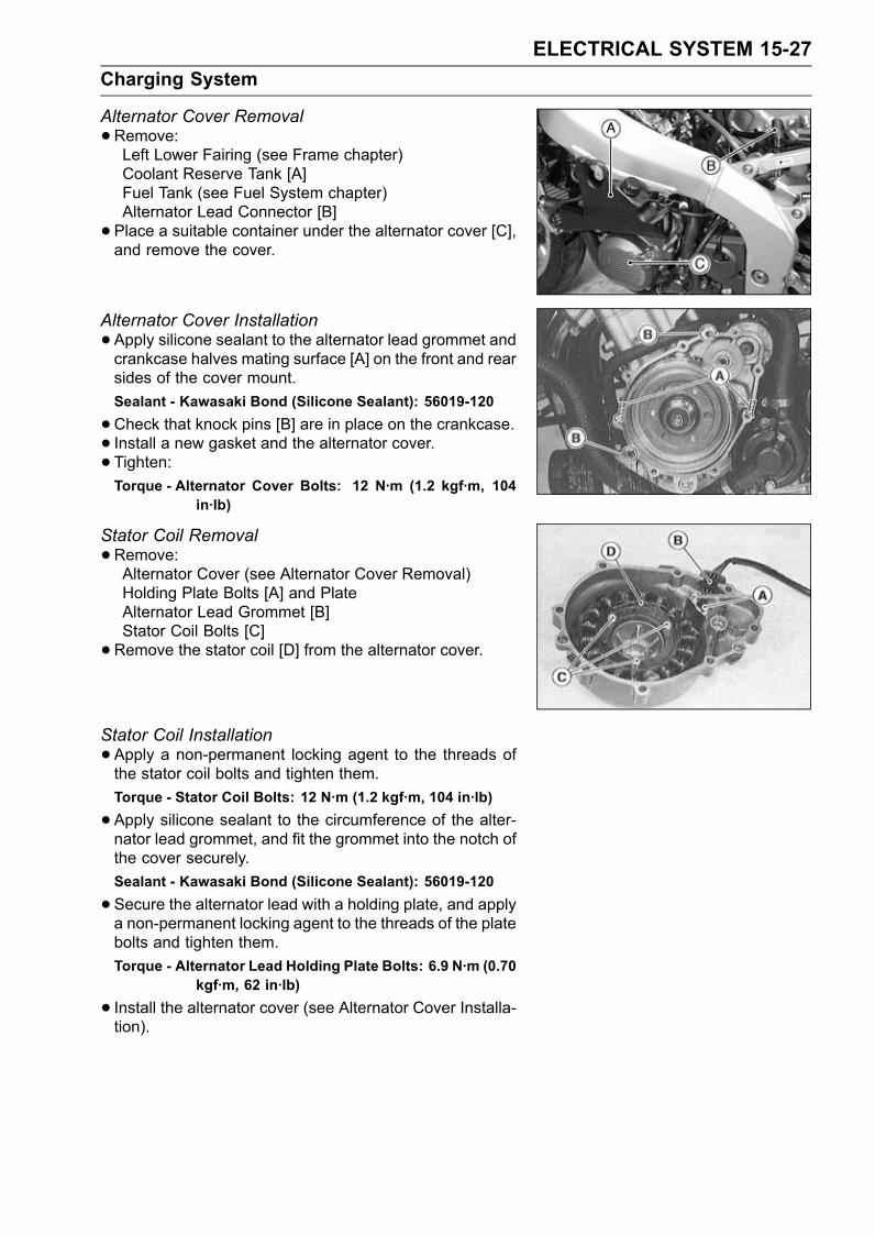
ELECTRICAL SYSTEM 15-27Charging System
Alternator Cover Removal•Remove:Left Lower Fairing (see Frame chapter)Coolant Reserve Tank [A]Fuel Tank (see Fuel System chapter)Alternator Lead Connector [B]• Place a suitable container under the alternator cover [C],and remove the cover.
Alternator Cover Installation•Apply silicone sealant to the alternator lead grommet andcrankcase halves mating surface [A] on the front and rearsides of the cover mount.Sealant - Kawasaki Bond (Silicone Sealant): 56019-120
•Check that knock pins [B] are in place on the crankcase.• Install a new gasket and the alternator cover.• Tighten:Torque - Alternator Cover Bolts: 12 N·m (1.2 kgf·m, 104
in·lb)
Stator Coil Removal•Remove:Alternator Cover (see Alternator Cover Removal)Holding Plate Bolts [A] and PlateAlternator Lead Grommet [B]Stator Coil Bolts [C]•Remove the stator coil [D] from the alternator cover.
Stator Coil Installation•Apply a non-permanent locking agent to the threads ofthe stator coil bolts and tighten them.Torque - Stator Coil Bolts: 12 N·m (1.2 kgf·m, 104 in·lb)
•Apply silicone sealant to the circumference of the alter-nator lead grommet, and fit the grommet into the notch ofthe cover securely.Sealant - Kawasaki Bond (Silicone Sealant): 56019-120
•Secure the alternator lead with a holding plate, and applya non-permanent locking agent to the threads of the platebolts and tighten them.Torque - Alternator Lead Holding Plate Bolts: 6.9 N·m (0.70
kgf·m, 62 in·lb)
• Install the alternator cover (see Alternator Cover Installa-tion).
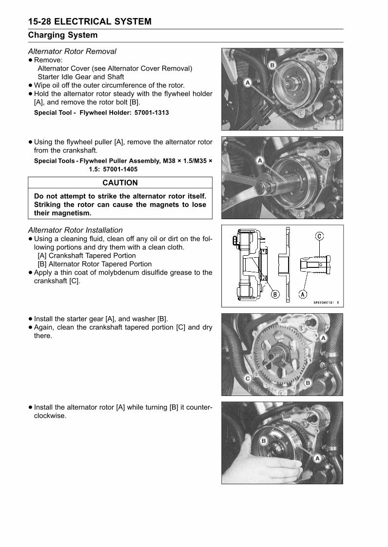
15-28 ELECTRICAL SYSTEMCharging System
Alternator Rotor Removal•Remove:Alternator Cover (see Alternator Cover Removal)Starter Idle Gear and Shaft•Wipe oil off the outer circumference of the rotor.• Hold the alternator rotor steady with the flywheel holder[A], and remove the rotor bolt [B].Special Tool - Flywheel Holder: 57001-1313
•Using the flywheel puller [A], remove the alternator rotorfrom the crankshaft.Special Tools - Flywheel Puller Assembly, M38 × 1.5/M35 ×
1.5: 57001-1405
CAUTIONDo not attempt to strike the alternator rotor itself.Striking the rotor can cause the magnets to losetheir magnetism.
Alternator Rotor Installation•Using a cleaning fluid, clean off any oil or dirt on the fol-lowing portions and dry them with a clean cloth.[A] Crankshaft Tapered Portion[B] Alternator Rotor Tapered Portion•Apply a thin coat of molybdenum disulfide grease to thecrankshaft [C].
• Install the starter gear [A], and washer [B].• Again, clean the crankshaft tapered portion [C] and drythere.
• Install the alternator rotor [A] while turning [B] it counter-clockwise.
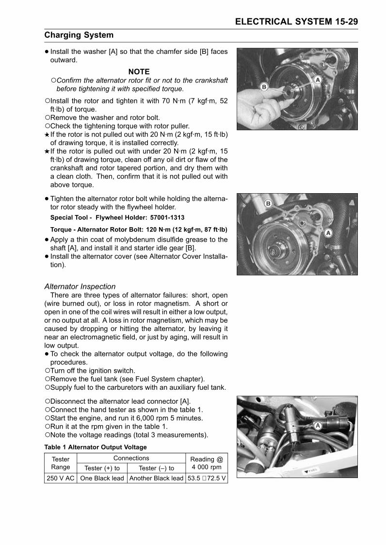
ELECTRICAL SYSTEM 15-29Charging System
• Install the washer [A] so that the chamfer side [B] facesoutward.
NOTEConfirm the alternator rotor fit or not to the crankshaftbefore tightening it with specified torque.
Install the rotor and tighten it with 70 N·m (7 kgf·m, 52ft·lb) of torque.Remove the washer and rotor bolt.Check the tightening torque with rotor puller.If the rotor is not pulled out with 20 N·m (2 kgf·m, 15 ft·lb)of drawing torque, it is installed correctly.If the rotor is pulled out with under 20 N·m (2 kgf·m, 15ft·lb) of drawing torque, clean off any oil dirt or flaw of thecrankshaft and rotor tapered portion, and dry them witha clean cloth. Then, confirm that it is not pulled out withabove torque.
• Tighten the alternator rotor bolt while holding the alterna-tor rotor steady with the flywheel holder.Special Tool - Flywheel Holder: 57001-1313
Torque - Alternator Rotor Bolt: 120 N·m (12 kgf·m, 87 ft·lb)
•Apply a thin coat of molybdenum disulfide grease to theshaft [A], and install it and starter idle gear [B].• Install the alternator cover (see Alternator Cover Installa-tion).
Alternator InspectionThere are three types of alternator failures: short, open
(wire burned out), or loss in rotor magnetism. A short oropen in one of the coil wires will result in either a low output,or no output at all. A loss in rotor magnetism, which may becaused by dropping or hitting the alternator, by leaving itnear an electromagnetic field, or just by aging, will result inlow output.• To check the alternator output voltage, do the followingprocedures.Turn off the ignition switch.Remove the fuel tank (see Fuel System chapter).Supply fuel to the carburetors with an auxiliary fuel tank.Disconnect the alternator lead connector [A].Connect the hand tester as shown in the table 1.Start the engine, and run it 6,000 rpm 5 minutes.Run it at the rpm given in the table 1.Note the voltage readings (total 3 measurements).Table 1 Alternator Output Voltage
ConnectionsTesterRange Tester (+) to Tester (–) to
Reading @4 000 rpm
250 V AC One Black lead Another Black lead 53.5 ∼ 72.5 V
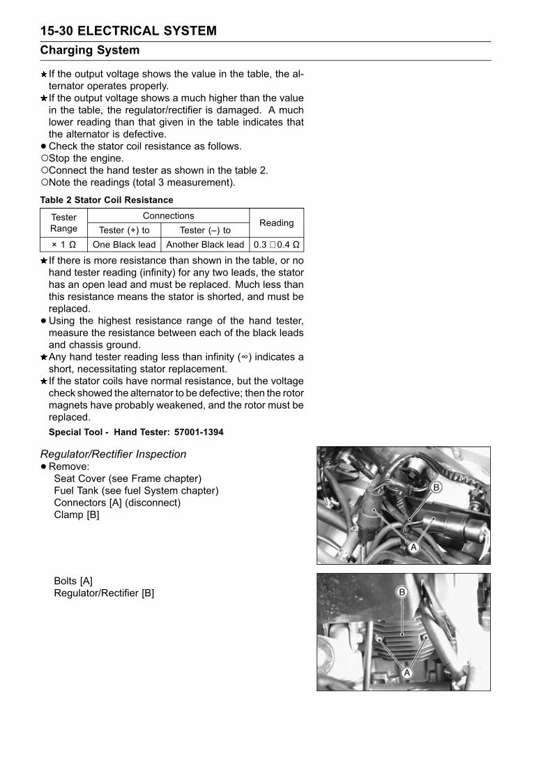
15-30 ELECTRICAL SYSTEMCharging System
If the output voltage shows the value in the table, the al-ternator operates properly.If the output voltage shows a much higher than the valuein the table, the regulator/rectifier is damaged. A muchlower reading than that given in the table indicates thatthe alternator is defective.•Check the stator coil resistance as follows.Stop the engine.Connect the hand tester as shown in the table 2.Note the readings (total 3 measurement).Table 2 Stator Coil Resistance
ConnectionsTesterRange Tester (+) to Tester (–) to
Reading
× 1 Ω One Black lead Another Black lead 0.3 ∼ 0.4 Ω
If there is more resistance than shown in the table, or nohand tester reading (infinity) for any two leads, the statorhas an open lead and must be replaced. Much less thanthis resistance means the stator is shorted, and must bereplaced.•Using the highest resistance range of the hand tester,measure the resistance between each of the black leadsand chassis ground.Any hand tester reading less than infinity (∞) indicates ashort, necessitating stator replacement.If the stator coils have normal resistance, but the voltagecheck showed the alternator to be defective; then the rotormagnets have probably weakened, and the rotor must bereplaced.Special Tool - Hand Tester: 57001-1394
Regulator/Rectifier Inspection•Remove:Seat Cover (see Frame chapter)Fuel Tank (see fuel System chapter)Connectors [A] (disconnect)Clamp [B]
Bolts [A]Regulator/Rectifier [B]
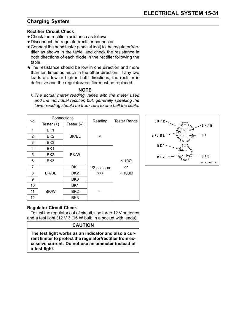
ELECTRICAL SYSTEM 15-31Charging System
Rectifier Circuit Check•Check the rectifier resistance as follows.•Disconnect the regulator/rectifier connector.• Connect the hand tester (special tool) to the regulator/rec-tifier as shown in the table, and check the resistance inboth directions of each diode in the rectifier following thetable.The resistance should be low in one direction and morethan ten times as much in the other direction. If any twoleads are low or high in both directions, the rectifier isdefective and the regulator/rectifier must be replaced.
NOTEThe actual meter reading varies with the meter usedand the individual rectifier, but, generally speaking thelower reading should be from zero to one half the scale.
ConnectionsNo.
Tester (+) Tester (–)Reading Tester Range
1 BK12 BK2 BK/BL ∞3 BK34 BK15 BK2 BK/W6 BK3 × 10Ω7 BK1 or8 BK/BL BK2
1/2 scale orless × 100Ω
9 BK310 BK111 BK/W BK2 ∞12 BK3
Regulator Circuit CheckTo test the regulator out of circuit, use three 12 V batteries
and a test light (12 V 3 ∼ 6 W bulb in a socket with leads).
CAUTIONThe test light works as an indicator and also a cur-rent limiter to protect the regulator/rectifier from ex-cessive current. Do not use an ammeter instead ofa test light.
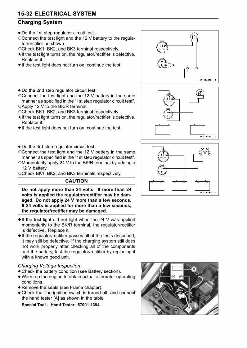
15-32 ELECTRICAL SYSTEMCharging System
•Do the 1st step regulator circuit test.Connect the test light and the 12 V battery to the regula-tor/rectifier as shown.Check BK1, BK2, and BK3 terminal respectively.If the test light turns on, the regulator/rectifier is defective.Replace it.If the test light does not turn on, continue the test.
• Do the 2nd step regulator circuit test.Connect the test light and the 12 V battery in the samemanner as specified in the "1st step regulator circuit test".Apply 12 V to the BK/R terminal.Check BK1, BK2, and BK3 terminal respectively.If the test light turns on, the regulator/rectifier is defective.Replace it.If the test light does not turn on, continue the test.
• Do the 3rd step regulator circuit testConnect the test light and the 12 V battery in the samemanner as specified in the "1st step regulator circuit test".Momentarily apply 24 V to the BK/R terminal by adding a12 V battery.Check BK1, BK2, and BK3 terminals respectively.
CAUTIONDo not apply more than 24 volts. If more than 24volts is applied the regulator/rectifier may be dam-aged. Do not apply 24 V more than a few seconds.If 24 volts is applied for more than a few seconds,the regulator/rectifier may be damaged.
If the test light did not light when the 24 V was appliedmomentarily to the BK/R terminal, the regulator/rectifieris defective. Replace it.If the regulator/rectifier passes all of the tests described,it may still be defective. If the charging system still doesnot work properly after checking all of the componentsand the battery, test the regulator/rectifier by replacing itwith a known good unit.
Charging Voltage Inspection•Check the battery condition (see Battery section).•Warm up the engine to obtain actual alternator operatingconditions.•Remove the seats (see Frame chapter).• Check that the ignition switch is turned off, and connectthe hand tester [A] as shown in the table.Special Tool - Hand Tester: 57001-1394
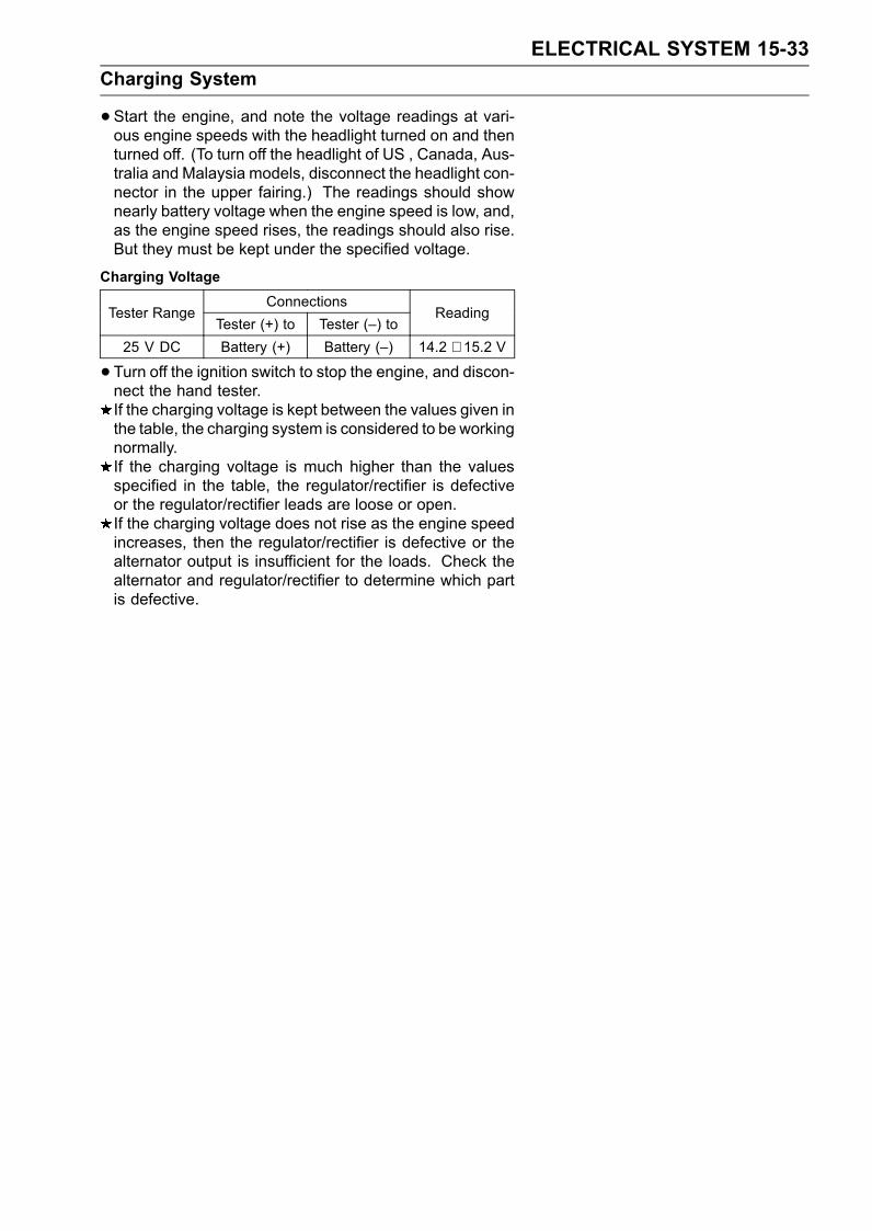
ELECTRICAL SYSTEM 15-33Charging System
•Start the engine, and note the voltage readings at vari-ous engine speeds with the headlight turned on and thenturned off. (To turn off the headlight of US , Canada, Aus-tralia and Malaysia models, disconnect the headlight con-nector in the upper fairing.) The readings should shownearly battery voltage when the engine speed is low, and,as the engine speed rises, the readings should also rise.But they must be kept under the specified voltage.
Charging VoltageConnections
Tester RangeTester (+) to Tester (–) to
Reading
25 V DC Battery (+) Battery (–) 14.2 ∼ 15.2 V
• Turn off the ignition switch to stop the engine, and discon-nect the hand tester.If the charging voltage is kept between the values given inthe table, the charging system is considered to be workingnormally.If the charging voltage is much higher than the valuesspecified in the table, the regulator/rectifier is defectiveor the regulator/rectifier leads are loose or open.If the charging voltage does not rise as the engine speedincreases, then the regulator/rectifier is defective or thealternator output is insufficient for the loads. Check thealternator and regulator/rectifier to determine which partis defective.
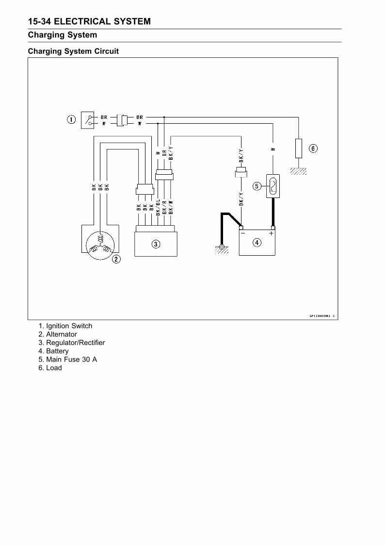
15-34 ELECTRICAL SYSTEMCharging System
Charging System Circuit
1. Ignition Switch2. Alternator3. Regulator/Rectifier4. Battery5. Main Fuse 30 A6. Load
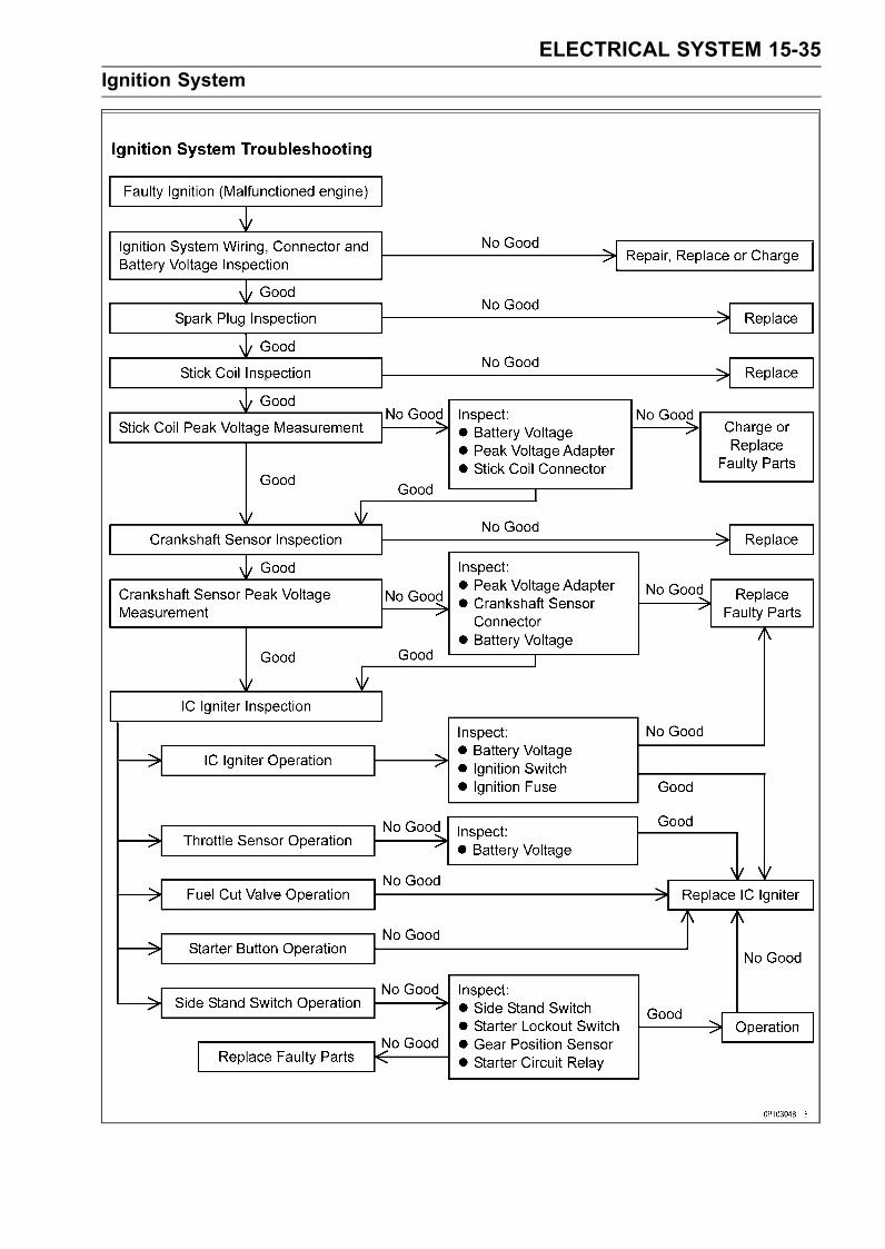
ELECTRICAL SYSTEM 15-35Ignition System
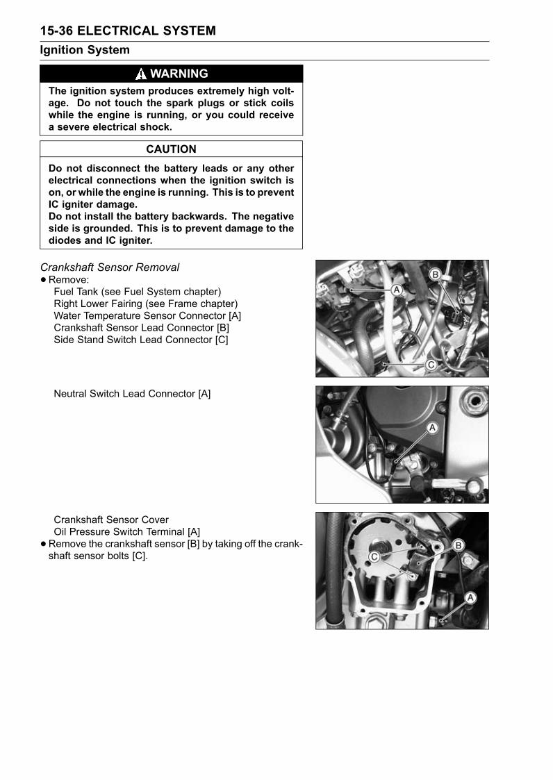
15-36 ELECTRICAL SYSTEMIgnition System
WARNINGThe ignition system produces extremely high volt-age. Do not touch the spark plugs or stick coilswhile the engine is running, or you could receivea severe electrical shock.
CAUTIONDo not disconnect the battery leads or any otherelectrical connections when the ignition switch ison, or while the engine is running. This is to preventIC igniter damage.Do not install the battery backwards. The negativeside is grounded. This is to prevent damage to thediodes and IC igniter.
Crankshaft Sensor Removal•Remove:Fuel Tank (see Fuel System chapter)Right Lower Fairing (see Frame chapter)Water Temperature Sensor Connector [A]Crankshaft Sensor Lead Connector [B]Side Stand Switch Lead Connector [C]
Neutral Switch Lead Connector [A]
Crankshaft Sensor CoverOil Pressure Switch Terminal [A]•Remove the crankshaft sensor [B] by taking off the crank-shaft sensor bolts [C].
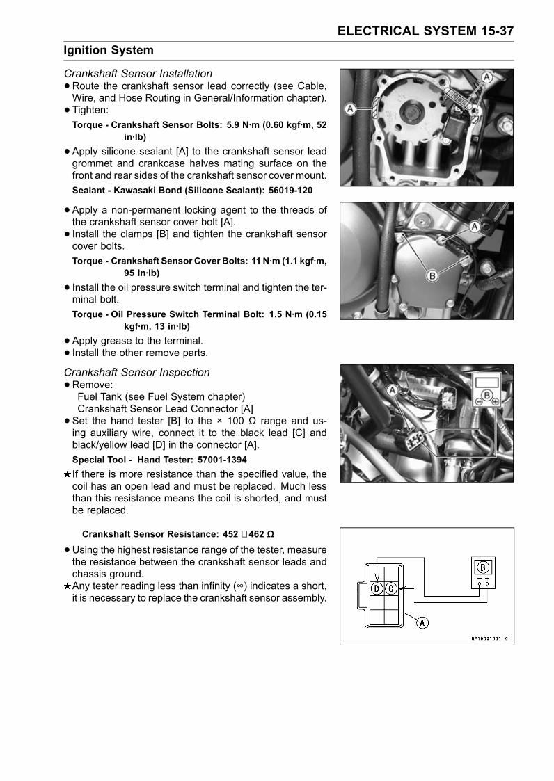
ELECTRICAL SYSTEM 15-37Ignition System
Crankshaft Sensor Installation•Route the crankshaft sensor lead correctly (see Cable,Wire, and Hose Routing in General/Information chapter).• Tighten:Torque - Crankshaft Sensor Bolts: 5.9 N·m (0.60 kgf·m, 52
in·lb)
•Apply silicone sealant [A] to the crankshaft sensor leadgrommet and crankcase halves mating surface on thefront and rear sides of the crankshaft sensor cover mount.Sealant - Kawasaki Bond (Silicone Sealant): 56019-120
•Apply a non-permanent locking agent to the threads ofthe crankshaft sensor cover bolt [A].• Install the clamps [B] and tighten the crankshaft sensorcover bolts.Torque - Crankshaft Sensor Cover Bolts: 11 N·m (1.1 kgf·m,
95 in·lb)
• Install the oil pressure switch terminal and tighten the ter-minal bolt.Torque - Oil Pressure Switch Terminal Bolt: 1.5 N·m (0.15
kgf·m, 13 in·lb)
•Apply grease to the terminal.• Install the other remove parts.Crankshaft Sensor Inspection•Remove:Fuel Tank (see Fuel System chapter)Crankshaft Sensor Lead Connector [A]• Set the hand tester [B] to the × 100 Ω range and us-ing auxiliary wire, connect it to the black lead [C] andblack/yellow lead [D] in the connector [A].Special Tool - Hand Tester: 57001-1394If there is more resistance than the specified value, thecoil has an open lead and must be replaced. Much lessthan this resistance means the coil is shorted, and mustbe replaced.
Crankshaft Sensor Resistance: 452 ∼ 462 Ω
•Using the highest resistance range of the tester, measurethe resistance between the crankshaft sensor leads andchassis ground.Any tester reading less than infinity (∞) indicates a short,it is necessary to replace the crankshaft sensor assembly.
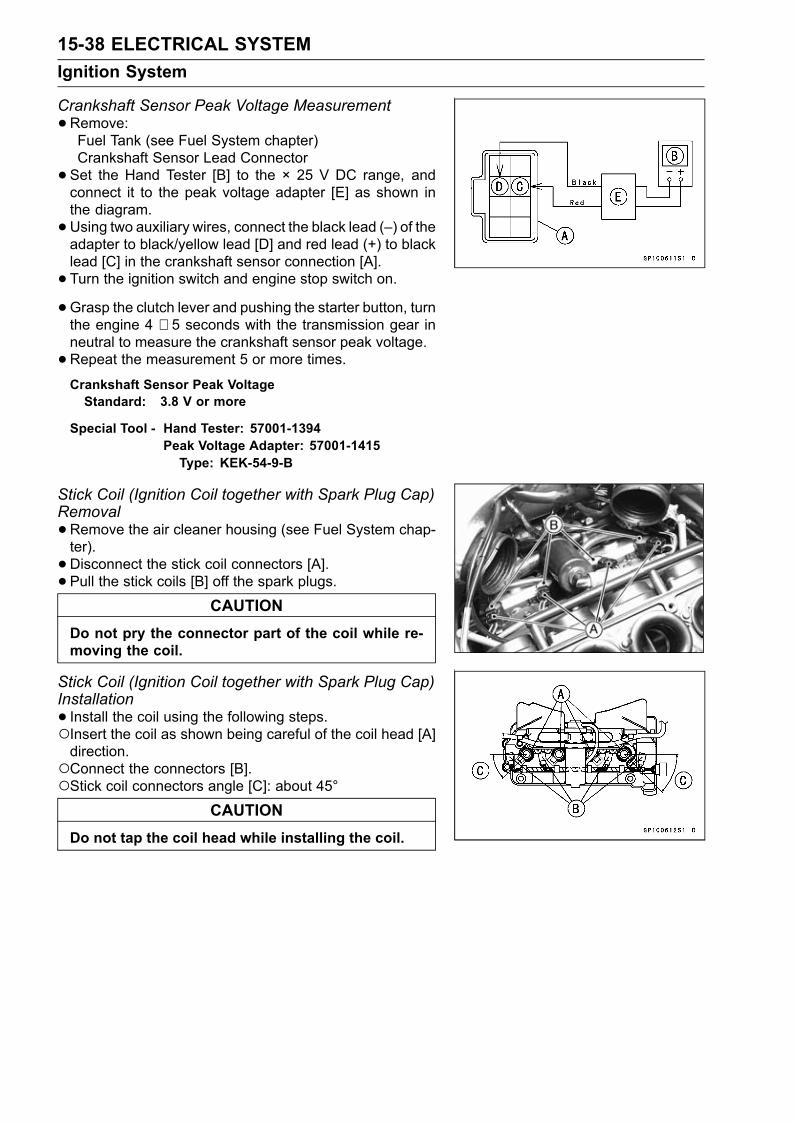
15-38 ELECTRICAL SYSTEMIgnition System
Crankshaft Sensor Peak Voltage Measurement•Remove:Fuel Tank (see Fuel System chapter)Crankshaft Sensor Lead Connector• Set the Hand Tester [B] to the × 25 V DC range, andconnect it to the peak voltage adapter [E] as shown inthe diagram.•Using two auxiliary wires, connect the black lead (–) of theadapter to black/yellow lead [D] and red lead (+) to blacklead [C] in the crankshaft sensor connection [A].• Turn the ignition switch and engine stop switch on.•Grasp the clutch lever and pushing the starter button, turnthe engine 4 ∼ 5 seconds with the transmission gear inneutral to measure the crankshaft sensor peak voltage.•Repeat the measurement 5 or more times.Crankshaft Sensor Peak VoltageStandard: 3.8 V or more
Special Tool - Hand Tester: 57001-1394Peak Voltage Adapter: 57001-1415Type: KEK-54-9-B
Stick Coil (Ignition Coil together with Spark Plug Cap)Removal•Remove the air cleaner housing (see Fuel System chap-ter).• Disconnect the stick coil connectors [A].• Pull the stick coils [B] off the spark plugs.
CAUTIONDo not pry the connector part of the coil while re-moving the coil.
Stick Coil (Ignition Coil together with Spark Plug Cap)Installation• Install the coil using the following steps.Insert the coil as shown being careful of the coil head [A]direction.Connect the connectors [B].Stick coil connectors angle [C]: about 45°
CAUTIONDo not tap the coil head while installing the coil.
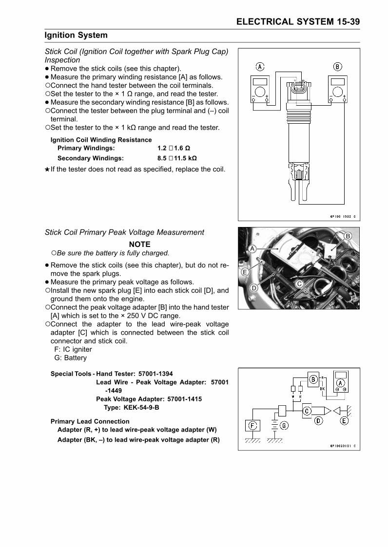
ELECTRICAL SYSTEM 15-39Ignition System
Stick Coil (Ignition Coil together with Spark Plug Cap)Inspection•Remove the stick coils (see this chapter).•Measure the primary winding resistance [A] as follows.Connect the hand tester between the coil terminals.Set the tester to the × 1 Ω range, and read the tester.•Measure the secondary winding resistance [B] as follows.Connect the tester between the plug terminal and (–) coilterminal.Set the tester to the × 1 kΩ range and read the tester.Ignition Coil Winding ResistancePrimary Windings: 1.2 ∼ 1.6 ΩSecondary Windings: 8.5 ∼ 11.5 kΩ
If the tester does not read as specified, replace the coil.
Stick Coil Primary Peak Voltage MeasurementNOTE
Be sure the battery is fully charged.•Remove the stick coils (see this chapter), but do not re-move the spark plugs.•Measure the primary peak voltage as follows.Install the new spark plug [E] into each stick coil [D], andground them onto the engine.Connect the peak voltage adapter [B] into the hand tester[A] which is set to the × 250 V DC range.Connect the adapter to the lead wire-peak voltageadapter [C] which is connected between the stick coilconnector and stick coil.F: IC igniterG: Battery
Special Tools - Hand Tester: 57001-1394Lead Wire - Peak Voltage Adapter: 57001-1449
Peak Voltage Adapter: 57001-1415Type: KEK-54-9-B
Primary Lead ConnectionAdapter (R, +) to lead wire-peak voltage adapter (W)Adapter (BK, –) to lead wire-peak voltage adapter (R)
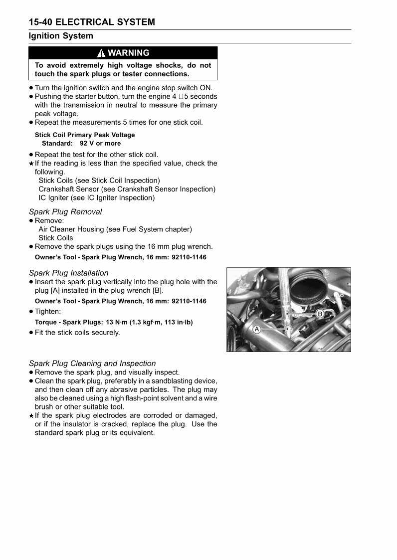
15-40 ELECTRICAL SYSTEMIgnition System
WARNINGTo avoid extremely high voltage shocks, do nottouch the spark plugs or tester connections.
•Turn the ignition switch and the engine stop switch ON.•Pushing the starter button, turn the engine 4 ∼ 5 secondswith the transmission in neutral to measure the primarypeak voltage.•Repeat the measurements 5 times for one stick coil.Stick Coil Primary Peak VoltageStandard: 92 V or more
•Repeat the test for the other stick coil.If the reading is less than the specified value, check thefollowing.Stick Coils (see Stick Coil Inspection)Crankshaft Sensor (see Crankshaft Sensor Inspection)IC Igniter (see IC Igniter Inspection)
Spark Plug Removal•Remove:Air Cleaner Housing (see Fuel System chapter)Stick Coils•Remove the spark plugs using the 16 mm plug wrench.Owner’s Tool - Spark Plug Wrench, 16 mm: 92110-1146
Spark Plug Installation• Insert the spark plug vertically into the plug hole with theplug [A] installed in the plug wrench [B].Owner’s Tool - Spark Plug Wrench, 16 mm: 92110-1146
•Tighten:Torque - Spark Plugs: 13 N·m (1.3 kgf·m, 113 in·lb)
•Fit the stick coils securely.
Spark Plug Cleaning and Inspection•Remove the spark plug, and visually inspect.• Clean the spark plug, preferably in a sandblasting device,and then clean off any abrasive particles. The plug mayalso be cleaned using a high flash-point solvent and a wirebrush or other suitable tool.If the spark plug electrodes are corroded or damaged,or if the insulator is cracked, replace the plug. Use thestandard spark plug or its equivalent.
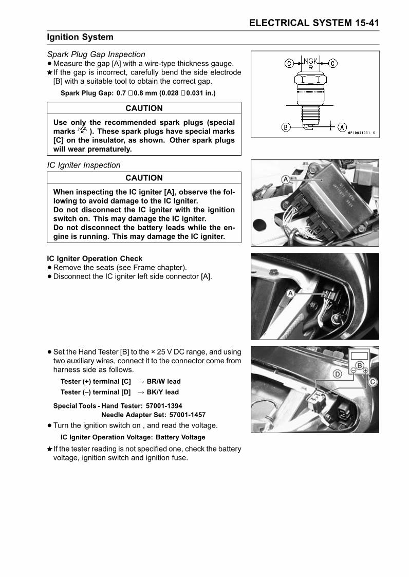
ELECTRICAL SYSTEM 15-41Ignition System
Spark Plug Gap Inspection•Measure the gap [A] with a wire-type thickness gauge.If the gap is incorrect, carefully bend the side electrode[B] with a suitable tool to obtain the correct gap.Spark Plug Gap: 0.7 ∼ 0.8 mm (0.028 ∼ 0.031 in.)
CAUTIONUse only the recommended spark plugs (specialmarks ). These spark plugs have special marks[C] on the insulator, as shown. Other spark plugswill wear prematurely.
IC Igniter InspectionCAUTION
When inspecting the IC igniter [A], observe the fol-lowing to avoid damage to the IC Igniter.Do not disconnect the IC igniter with the ignitionswitch on. This may damage the IC igniter.Do not disconnect the battery leads while the en-gine is running. This may damage the IC igniter.
IC Igniter Operation Check•Remove the seats (see Frame chapter).• Disconnect the IC igniter left side connector [A].
• Set the Hand Tester [B] to the × 25 V DC range, and usingtwo auxiliary wires, connect it to the connector come fromharness side as follows.Tester (+) terminal [C] → BR/W leadTester (–) terminal [D] → BK/Y lead
Special Tools - Hand Tester: 57001-1394Needle Adapter Set: 57001-1457
•Turn the ignition switch on , and read the voltage.IC Igniter Operation Voltage: Battery Voltage
If the tester reading is not specified one, check the batteryvoltage, ignition switch and ignition fuse.
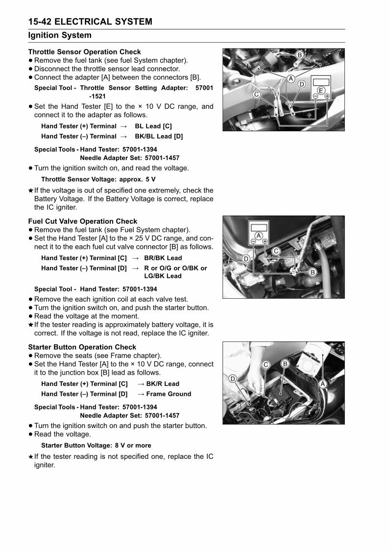
15-42 ELECTRICAL SYSTEMIgnition System
Throttle Sensor Operation Check•Remove the fuel tank (see fuel System chapter).• Disconnect the throttle sensor lead connector.• Connect the adapter [A] between the connectors [B].Special Tool - Throttle Sensor Setting Adapter: 57001
-1521
•Set the Hand Tester [E] to the × 10 V DC range, andconnect it to the adapter as follows.Hand Tester (+) Terminal → BL Lead [C]Hand Tester (–) Terminal → BK/BL Lead [D]
Special Tools - Hand Tester: 57001-1394Needle Adapter Set: 57001-1457
•Turn the ignition switch on, and read the voltage.Throttle Sensor Voltage: approx. 5 V
If the voltage is out of specified one extremely, check theBattery Voltage. If the Battery Voltage is correct, replacethe IC igniter.
Fuel Cut Valve Operation Check•Remove the fuel tank (see Fuel System chapter).• Set the Hand Tester [A] to the × 25 V DC range, and con-nect it to the each fuel cut valve connector [B] as follows.Hand Tester (+) Terminal [C] → BR/BK LeadHand Tester (–) Terminal [D] → R or O/G or O/BK or
LG/BK Lead
Special Tool - Hand Tester: 57001-1394
•Remove the each ignition coil at each valve test.• Turn the ignition switch on, and push the starter button.•Read the voltage at the moment.If the tester reading is approximately battery voltage, it iscorrect. If the voltage is not read, replace the IC igniter.
Starter Button Operation Check•Remove the seats (see Frame chapter).• Set the Hand Tester [A] to the × 10 V DC range, connectit to the junction box [B] lead as follows.Hand Tester (+) Terminal [C] → BK/R LeadHand Tester (–) Terminal [D] → Frame Ground
Special Tools - Hand Tester: 57001-1394Needle Adapter Set: 57001-1457
•Turn the ignition switch on and push the starter button.•Read the voltage.Starter Button Voltage: 8 V or more
If the tester reading is not specified one, replace the ICigniter.
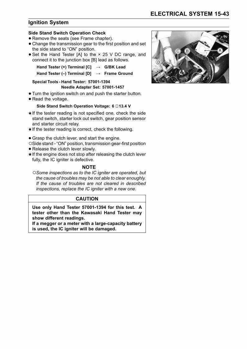
ELECTRICAL SYSTEM 15-43Ignition System
Side Stand Switch Operation Check•Remove the seats (see Frame chapter).• Change the transmission gear to the first position and setthe side stand to “ON” position.• Set the Hand Tester [A] to the × 25 V DC range, andconnect it to the junction box [B] lead as follows.Hand Tester (+) Terminal [C] → G/BK LeadHand Tester (–) Terminal [D] → Frame Ground
Special Tools - Hand Tester: 57001-1394Needle Adapter Set: 57001-1457
•Turn the ignition switch on and push the starter button.•Read the voltage.Side Stand Switch Operation Voltage: 6 ∼ 13.4 V
If the tester reading is not specified one, check the sidestand switch, starter lock out switch, gear position sensorand starter circuit relay.If the tester reading is correct, check the following.
•Grasp the clutch lever, and start the engine.Side stand - “ON” position, transmission gear-first position•Release the clutch lever slowly.If the engine does not stop after releasing the clutch leverfully, the IC igniter is defective.
NOTESome inspections as to the IC igniter are operated, butthe cause of troubles may be not able to clear enoughly.If the cause of troubles are not cleared in describedinspections, replace the IC igniter with a new one.
CAUTIONUse only Hand Tester 57001-1394 for this test. Atester other than the Kawasaki Hand Tester mayshow different readings.If a megger or a meter with a large-capacity batteryis used, the IC igniter will be damaged.

15-44 ELECTRICAL SYSTEMIgnition System
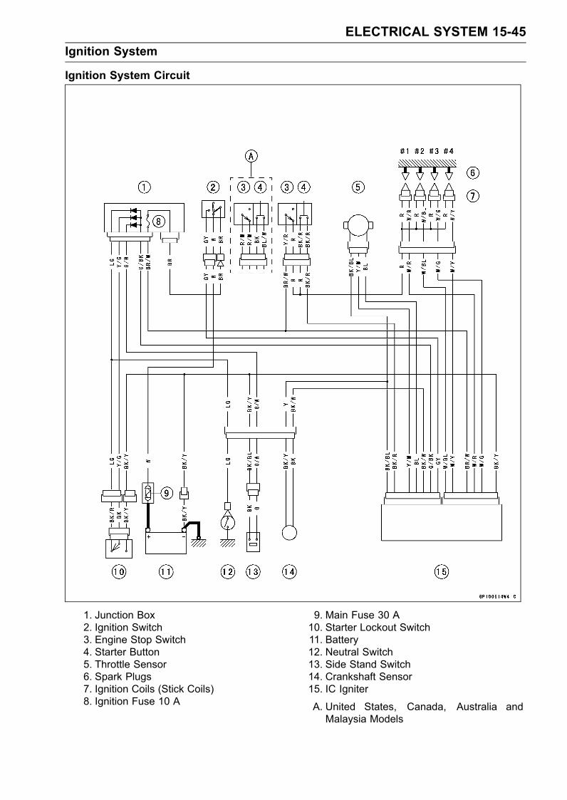
ELECTRICAL SYSTEM 15-45Ignition System
Ignition System Circuit
1. Junction Box2. Ignition Switch3. Engine Stop Switch4. Starter Button5. Throttle Sensor6. Spark Plugs7. Ignition Coils (Stick Coils)8. Ignition Fuse 10 A
9. Main Fuse 30 A10. Starter Lockout Switch11. Battery12. Neutral Switch13. Side Stand Switch14. Crankshaft Sensor15. IC Igniter
A. United States, Canada, Australia andMalaysia Models
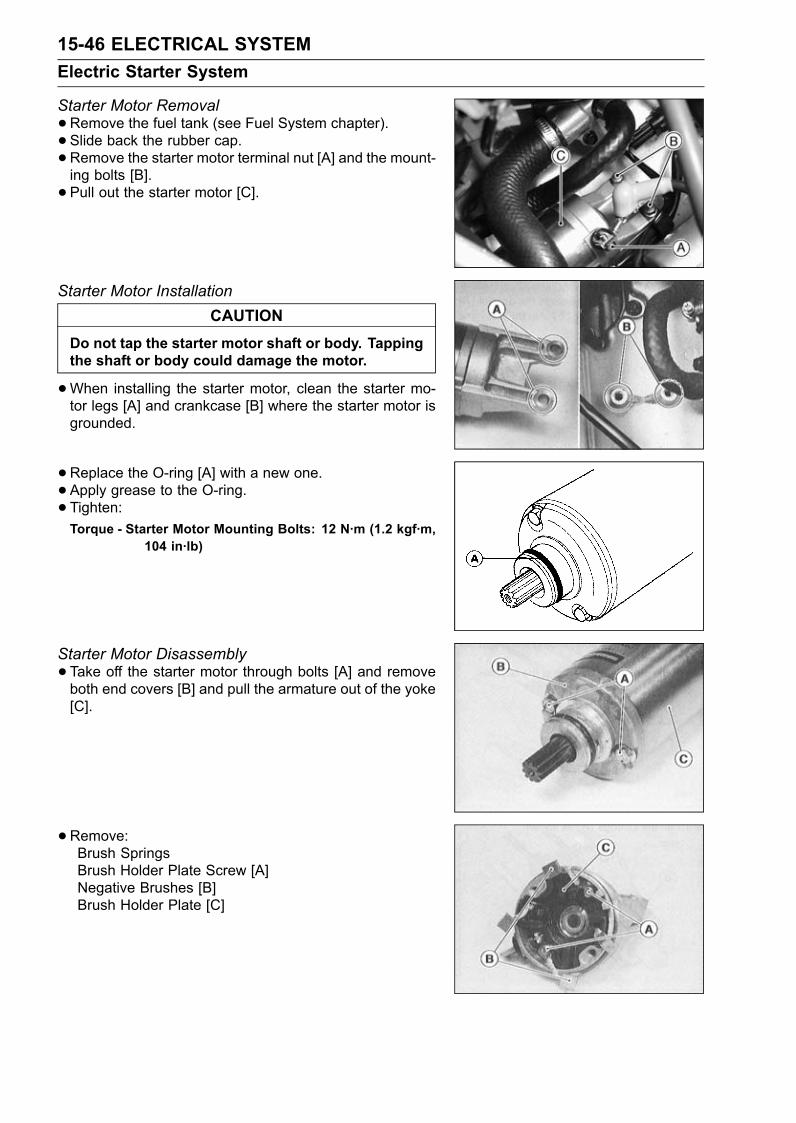
15-46 ELECTRICAL SYSTEMElectric Starter System
Starter Motor Removal•Remove the fuel tank (see Fuel System chapter).• Slide back the rubber cap.•Remove the starter motor terminal nut [A] and the mount-ing bolts [B].• Pull out the starter motor [C].
Starter Motor InstallationCAUTION
Do not tap the starter motor shaft or body. Tappingthe shaft or body could damage the motor.
•When installing the starter motor, clean the starter mo-tor legs [A] and crankcase [B] where the starter motor isgrounded.
•Replace the O-ring [A] with a new one.• Apply grease to the O-ring.• Tighten:Torque - Starter Motor Mounting Bolts: 12 N·m (1.2 kgf·m,
104 in·lb)
Starter Motor Disassembly•Take off the starter motor through bolts [A] and removeboth end covers [B] and pull the armature out of the yoke[C].
• Remove:Brush SpringsBrush Holder Plate Screw [A]Negative Brushes [B]Brush Holder Plate [C]
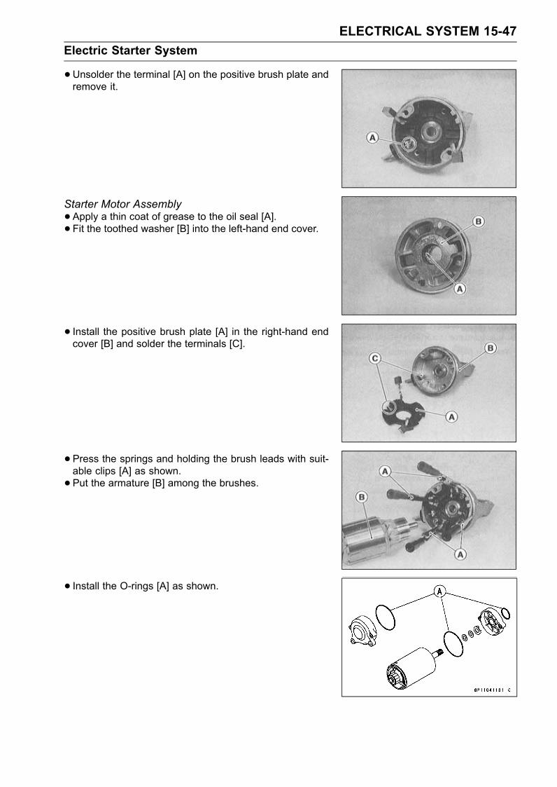
ELECTRICAL SYSTEM 15-47Electric Starter System
•Unsolder the terminal [A] on the positive brush plate andremove it.
Starter Motor Assembly•Apply a thin coat of grease to the oil seal [A].• Fit the toothed washer [B] into the left-hand end cover.
• Install the positive brush plate [A] in the right-hand endcover [B] and solder the terminals [C].
• Press the springs and holding the brush leads with suit-able clips [A] as shown.• Put the armature [B] among the brushes.
• Install the O-rings [A] as shown.
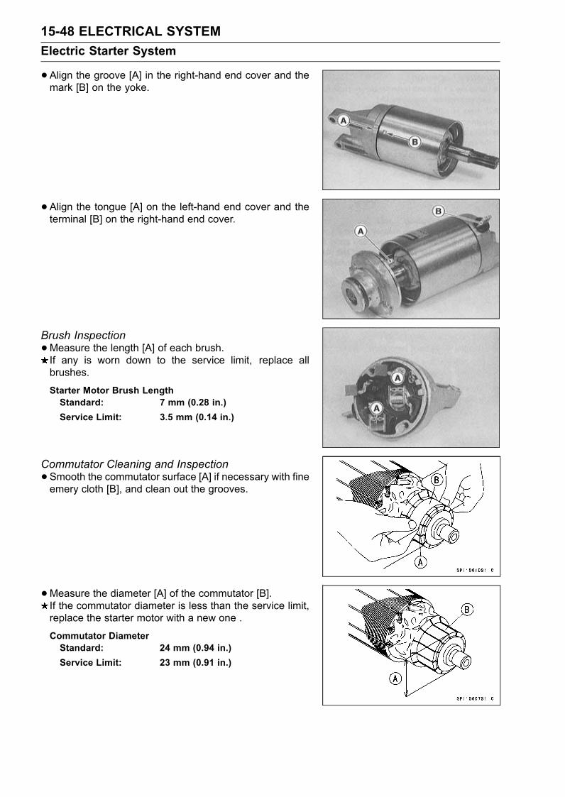
15-48 ELECTRICAL SYSTEMElectric Starter System
•Align the groove [A] in the right-hand end cover and themark [B] on the yoke.
• Align the tongue [A] on the left-hand end cover and theterminal [B] on the right-hand end cover.
Brush Inspection•Measure the length [A] of each brush.If any is worn down to the service limit, replace allbrushes.
Starter Motor Brush LengthStandard: 7 mm (0.28 in.)Service Limit: 3.5 mm (0.14 in.)
Commutator Cleaning and Inspection•Smooth the commutator surface [A] if necessary with fineemery cloth [B], and clean out the grooves.
•Measure the diameter [A] of the commutator [B].If the commutator diameter is less than the service limit,replace the starter motor with a new one .
Commutator DiameterStandard: 24 mm (0.94 in.)Service Limit: 23 mm (0.91 in.)
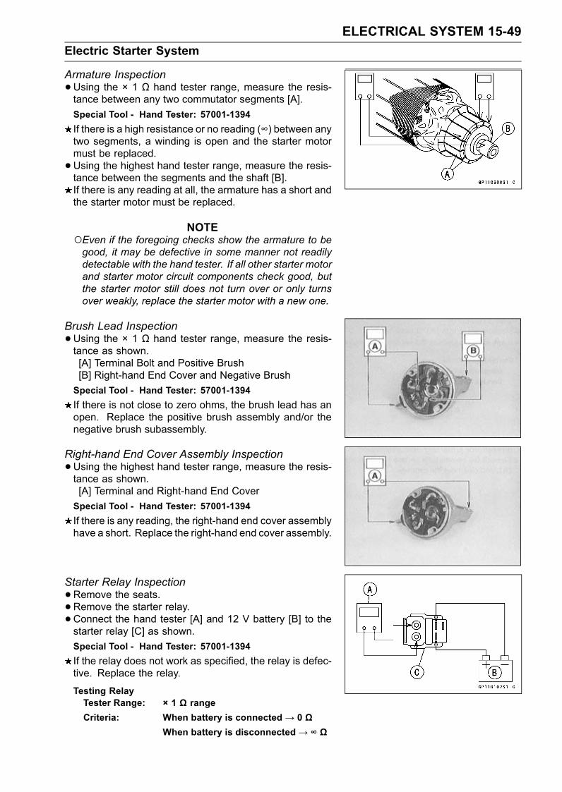
ELECTRICAL SYSTEM 15-49Electric Starter System
Armature Inspection•Using the × 1 Ω hand tester range, measure the resis-tance between any two commutator segments [A].Special Tool - Hand Tester: 57001-1394If there is a high resistance or no reading (∞) between anytwo segments, a winding is open and the starter motormust be replaced.•Using the highest hand tester range, measure the resis-tance between the segments and the shaft [B].If there is any reading at all, the armature has a short andthe starter motor must be replaced.
NOTEEven if the foregoing checks show the armature to begood, it may be defective in some manner not readilydetectable with the hand tester. If all other starter motorand starter motor circuit components check good, butthe starter motor still does not turn over or only turnsover weakly, replace the starter motor with a new one.
Brush Lead Inspection•Using the × 1 Ω hand tester range, measure the resis-tance as shown.[A] Terminal Bolt and Positive Brush[B] Right-hand End Cover and Negative BrushSpecial Tool - Hand Tester: 57001-1394If there is not close to zero ohms, the brush lead has anopen. Replace the positive brush assembly and/or thenegative brush subassembly.
Right-hand End Cover Assembly Inspection•Using the highest hand tester range, measure the resis-tance as shown.[A] Terminal and Right-hand End CoverSpecial Tool - Hand Tester: 57001-1394If there is any reading, the right-hand end cover assemblyhave a short. Replace the right-hand end cover assembly.
Starter Relay Inspection•Remove the seats.•Remove the starter relay.•Connect the hand tester [A] and 12 V battery [B] to thestarter relay [C] as shown.Special Tool - Hand Tester: 57001-1394If the relay does not work as specified, the relay is defec-tive. Replace the relay.
Testing RelayTester Range: × 1 Ω rangeCriteria: When battery is connected→ 0 Ω
When battery is disconnected→ ∞ Ω
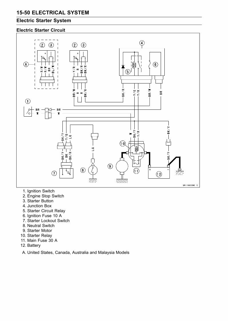
15-50 ELECTRICAL SYSTEMElectric Starter System
Electric Starter Circuit
1. Ignition Switch2. Engine Stop Switch3. Starter Button4. Junction Box5. Starter Circuit Relay6. Ignition Fuse 10 A7. Starter Lockout Switch8. Neutral Switch9. Starter Motor10. Starter Relay11. Main Fuse 30 A12. Battery
A. United States, Canada, Australia and Malaysia Models
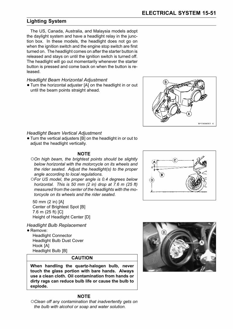
ELECTRICAL SYSTEM 15-51Lighting System
The US, Canada, Australia, and Malaysia models adoptthe daylight system and have a headlight relay in the junc-tion box. In these models, the headlight does not go onwhen the ignition switch and the engine stop switch are firstturned on. The headlight comes on after the starter button isreleased and stays on until the ignition switch is turned off.The headlight will go out momentarily whenever the starterbutton is pressed and come back on when the button is re-leased.
Headlight Beam Horizontal Adjustment•Turn the horizontal adjuster [A] on the headlight in or outuntil the beam points straight ahead.
Headlight Beam Vertical Adjustment•Turn the vertical adjusters [B] on the headlight in or out toadjust the headlight vertically.
NOTEOn high beam, the brightest points should be slightlybelow horizontal with the motorcycle on its wheels andthe rider seated. Adjust the headlight(s) to the properangle according to local regulations.For US model, the proper angle is 0.4 degrees belowhorizontal. This is 50 mm (2 in) drop at 7.6 m (25 ft)measured from the center of the headlights with the mo-torcycle on its wheels and the rider seated.
50 mm (2 in) [A]Center of Brightest Spot [B]7.6 m (25 ft) [C]Height of Headlight Center [D]
Headlight Bulb Replacement•Remove:Headlight ConnectorHeadlight Bulb Dust CoverHook [A]Headlight Bulb [B]
CAUTIONWhen handling the quartz-halogen bulb, nevertouch the glass portion with bare hands. Alwaysuse a clean cloth. Oil contamination from hands ordirty rags can reduce bulb life or cause the bulb toexplode.
NOTEClean off any contamination that inadvertently gets onthe bulb with alcohol or soap and water solution.
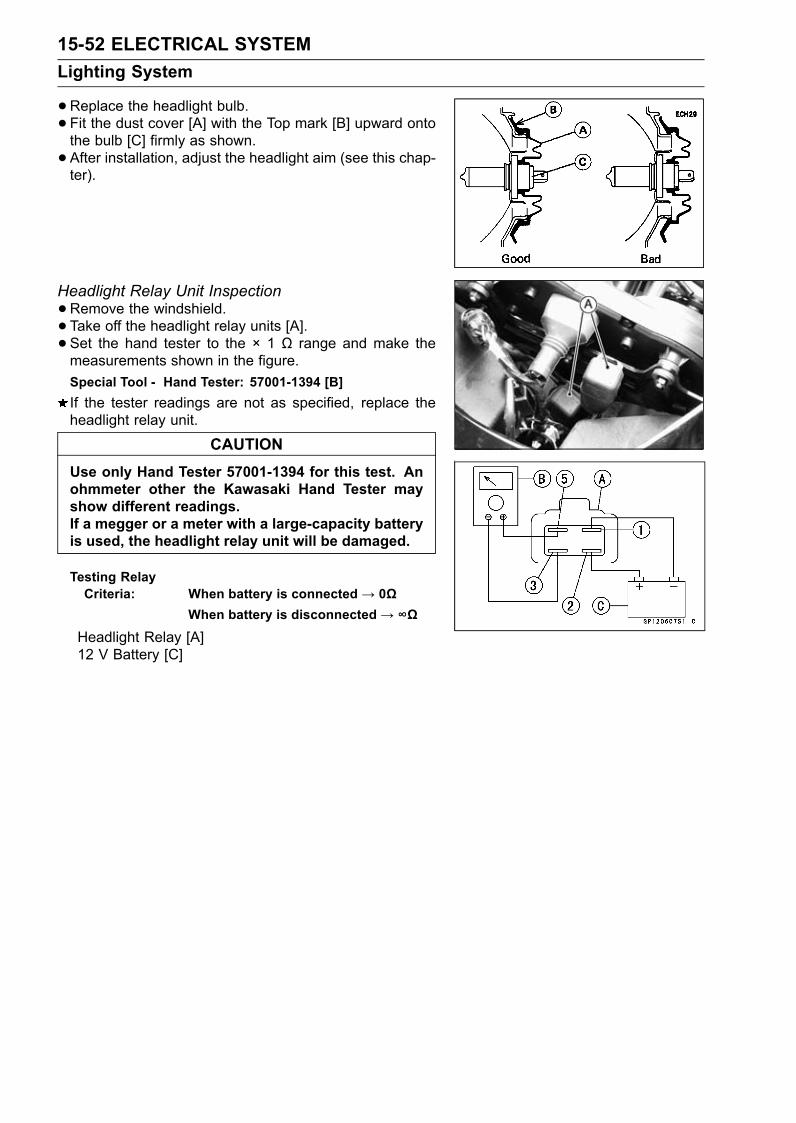
15-52 ELECTRICAL SYSTEMLighting System
•Replace the headlight bulb.• Fit the dust cover [A] with the Top mark [B] upward ontothe bulb [C] firmly as shown.• After installation, adjust the headlight aim (see this chap-ter).
Headlight Relay Unit Inspection•Remove the windshield.• Take off the headlight relay units [A].• Set the hand tester to the × 1 Ω range and make themeasurements shown in the figure.Special Tool - Hand Tester: 57001-1394 [B]If the tester readings are not as specified, replace theheadlight relay unit.
CAUTIONUse only Hand Tester 57001-1394 for this test. Anohmmeter other the Kawasaki Hand Tester mayshow different readings.If a megger or a meter with a large-capacity batteryis used, the headlight relay unit will be damaged.
Testing RelayCriteria: When battery is connected→ 0Ω
When battery is disconnected→ ∞Ω
Headlight Relay [A]12 V Battery [C]
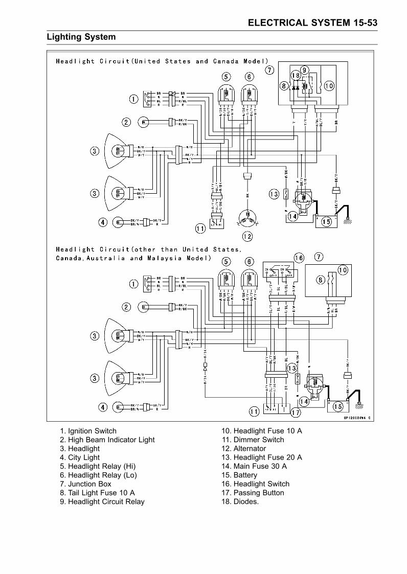
ELECTRICAL SYSTEM 15-53Lighting System
1. Ignition Switch2. High Beam Indicator Light3. Headlight4. City Light5. Headlight Relay (Hi)6. Headlight Relay (Lo)7. Junction Box8. Tail Light Fuse 10 A9. Headlight Circuit Relay
10. Headlight Fuse 10 A11. Dimmer Switch12. Alternator13. Headlight Fuse 20 A14. Main Fuse 30 A15. Battery16. Headlight Switch17. Passing Button18. Diodes.
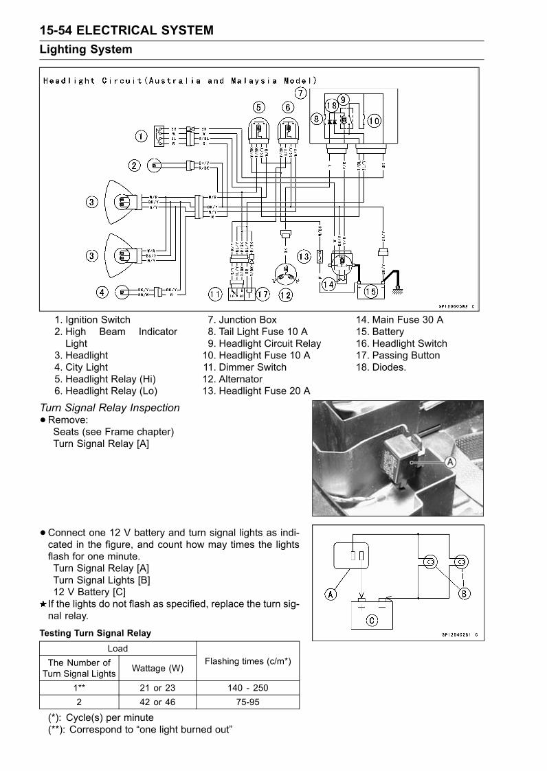
15-54 ELECTRICAL SYSTEMLighting System
1. Ignition Switch2. High Beam IndicatorLight
3. Headlight4. City Light5. Headlight Relay (Hi)6. Headlight Relay (Lo)
7. Junction Box8. Tail Light Fuse 10 A9. Headlight Circuit Relay10. Headlight Fuse 10 A11. Dimmer Switch12. Alternator13. Headlight Fuse 20 A
14. Main Fuse 30 A15. Battery16. Headlight Switch17. Passing Button18. Diodes.
Turn Signal Relay Inspection•Remove:Seats (see Frame chapter)Turn Signal Relay [A]
•Connect one 12 V battery and turn signal lights as indi-cated in the figure, and count how may times the lightsflash for one minute.Turn Signal Relay [A]Turn Signal Lights [B]12 V Battery [C]If the lights do not flash as specified, replace the turn sig-nal relay.
Testing Turn Signal RelayLoad
The Number ofTurn Signal Lights Wattage (W)
Flashing times (c/m*)
1** 21 or 23 140 - 2502 42 or 46 75-95
(*): Cycle(s) per minute(**): Correspond to “one light burned out”
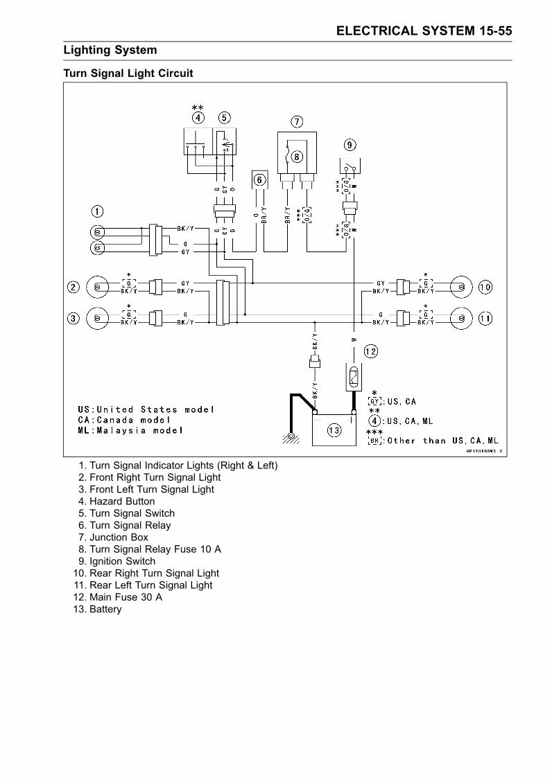
ELECTRICAL SYSTEM 15-55Lighting System
Turn Signal Light Circuit
1. Turn Signal Indicator Lights (Right & Left)2. Front Right Turn Signal Light3. Front Left Turn Signal Light4. Hazard Button5. Turn Signal Switch6. Turn Signal Relay7. Junction Box8. Turn Signal Relay Fuse 10 A9. Ignition Switch10. Rear Right Turn Signal Light11. Rear Left Turn Signal Light12. Main Fuse 30 A13. Battery
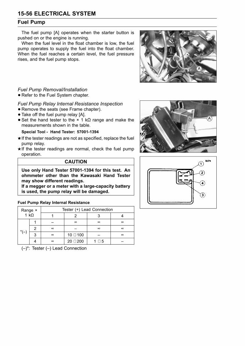
15-56 ELECTRICAL SYSTEMFuel Pump
The fuel pump [A] operates when the starter button ispushed on or the engine is running.When the fuel level in the float chamber is low, the fuel
pump operates to supply the fuel into the float chamber.When the fuel reaches a certain level, the fuel pressurerises, and the fuel pump stops.
Fuel Pump Removal/Installation•Refer to the Fuel System chapter.
Fuel Pump Relay Internal Resistance Inspection•Remove the seats (see Frame chapter).• Take off the fuel pump relay [A].• Set the hand tester to the × 1 kΩ range and make themeasurements shown in the table.Special Tool - Hand Tester: 57001-1394If the tester readings are not as specified, replace the fuelpump relay.If the tester readings are normal, check the fuel pumpoperation.
CAUTIONUse only Hand Tester 57001-1394 for this test. Anohmmeter other than the Kawasaki Hand Testermay show different readings.If a megger or a meter with a large-capacity batteryis used, the pump relay will be damaged.
Fuel Pump Relay Internal ResistanceTester (+) Lead ConnectionRange ×
1 kΩ 1 2 3 41 – ∞ ∞ ∞2 ∞ – ∞ ∞3 ∞ 10 ∼ 100 – ∞
*(–)
4 ∞ 20 ∼ 200 1 ∼ 5 –
(–)*: Tester (–) Lead Connection
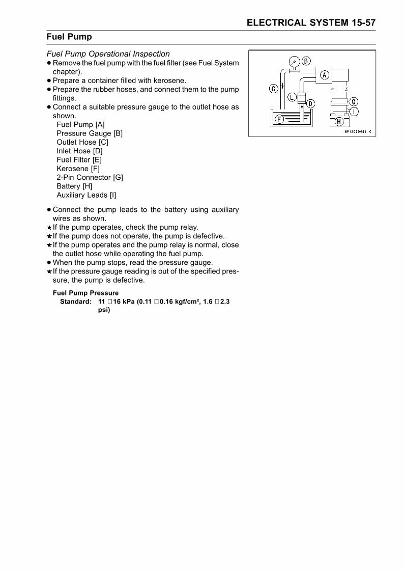
ELECTRICAL SYSTEM 15-57Fuel Pump
Fuel Pump Operational Inspection•Remove the fuel pumpwith the fuel filter (see Fuel Systemchapter).• Prepare a container filled with kerosene.• Prepare the rubber hoses, and connect them to the pumpfittings.•Connect a suitable pressure gauge to the outlet hose asshown.Fuel Pump [A]Pressure Gauge [B]Outlet Hose [C]Inlet Hose [D]Fuel Filter [E]Kerosene [F]2-Pin Connector [G]Battery [H]Auxiliary Leads [I]
• Connect the pump leads to the battery using auxiliarywires as shown.If the pump operates, check the pump relay.If the pump does not operate, the pump is defective.If the pump operates and the pump relay is normal, closethe outlet hose while operating the fuel pump.•When the pump stops, read the pressure gauge.If the pressure gauge reading is out of the specified pres-sure, the pump is defective.
Fuel Pump PressureStandard: 11 ∼ 16 kPa (0.11 ∼ 0.16 kgf/cm², 1.6 ∼ 2.3
psi)
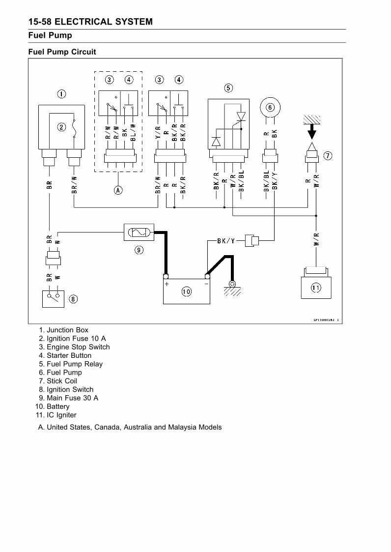
15-58 ELECTRICAL SYSTEMFuel Pump
Fuel Pump Circuit
1. Junction Box2. Ignition Fuse 10 A3. Engine Stop Switch4. Starter Button5. Fuel Pump Relay6. Fuel Pump7. Stick Coil8. Ignition Switch9. Main Fuse 30 A10. Battery11. IC Igniter
A. United States, Canada, Australia and Malaysia Models
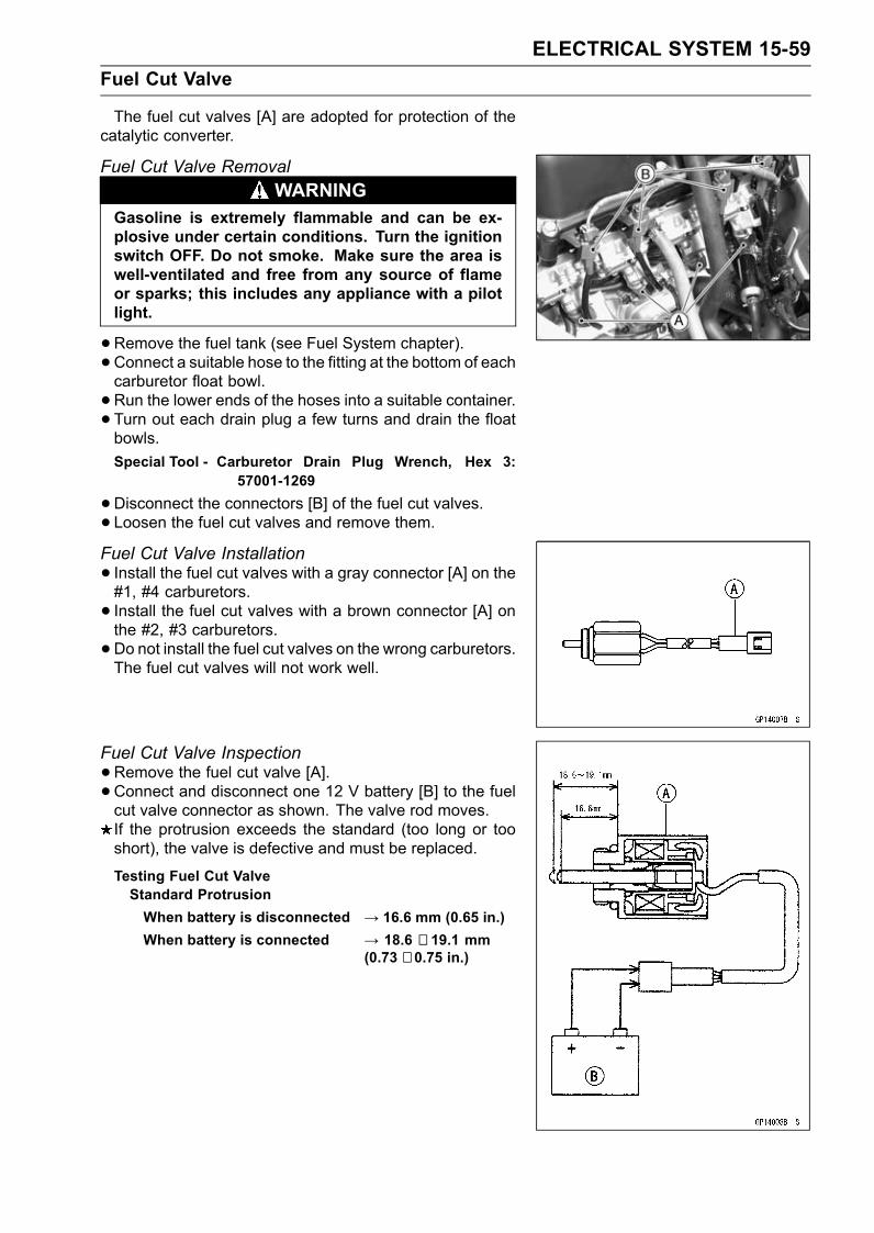
ELECTRICAL SYSTEM 15-59Fuel Cut Valve
The fuel cut valves [A] are adopted for protection of thecatalytic converter.
Fuel Cut Valve RemovalWARNING
Gasoline is extremely flammable and can be ex-plosive under certain conditions. Turn the ignitionswitch OFF. Do not smoke. Make sure the area iswell-ventilated and free from any source of flameor sparks; this includes any appliance with a pilotlight.
•Remove the fuel tank (see Fuel System chapter).• Connect a suitable hose to the fitting at the bottom of eachcarburetor float bowl.• Run the lower ends of the hoses into a suitable container.• Turn out each drain plug a few turns and drain the floatbowls.Special Tool - Carburetor Drain Plug Wrench, Hex 3:
57001-1269
•Disconnect the connectors [B] of the fuel cut valves.• Loosen the fuel cut valves and remove them.Fuel Cut Valve Installation• Install the fuel cut valves with a gray connector [A] on the#1, #4 carburetors.• Install the fuel cut valves with a brown connector [A] onthe #2, #3 carburetors.•Do not install the fuel cut valves on the wrong carburetors.The fuel cut valves will not work well.
Fuel Cut Valve Inspection•Remove the fuel cut valve [A].• Connect and disconnect one 12 V battery [B] to the fuelcut valve connector as shown. The valve rod moves.If the protrusion exceeds the standard (too long or tooshort), the valve is defective and must be replaced.
Testing Fuel Cut ValveStandard ProtrusionWhen battery is disconnected → 16.6 mm (0.65 in.)When battery is connected → 18.6 ∼ 19.1 mm
(0.73 ∼ 0.75 in.)
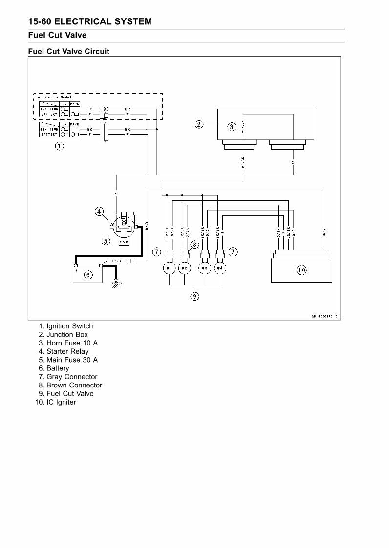
15-60 ELECTRICAL SYSTEMFuel Cut Valve
Fuel Cut Valve Circuit
1. Ignition Switch2. Junction Box3. Horn Fuse 10 A4. Starter Relay5. Main Fuse 30 A6. Battery7. Gray Connector8. Brown Connector9. Fuel Cut Valve10. IC Igniter
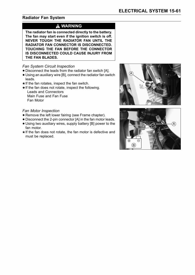
ELECTRICAL SYSTEM 15-61Radiator Fan System
WARNINGThe radiator fan is connected directly to the battery.The fan may start even if the ignition switch is off.NEVER TOUGH THE RADIATOR FAN UNTIL THERADIATOR FAN CONNECTOR IS DISCONNECTED.TOUCHING THE FAN BEFORE THE CONNECTORIS DISCONNECTED COULD CAUSE INJURY FROMTHE FAN BLADES.
Fan System Circuit Inspection•Disconnect the leads from the radiator fan switch [A].• Using an auxiliary wire [B], connect the radiator fan switchleads.If the fan rotates, inspect the fan switch.If the fan does not rotate, inspect the following.Leads and ConnectorsMain Fuse and Fan FuseFan Motor
Fan Motor Inspection•Remove the left lower fairing (see Frame chapter).• Disconnect the 2-pin connector [A] in the fan motor leads.•Using two auxiliary wires, supply battery [B] power to thefan motor.If the fan does not rotate, the fan motor is defective andmust be replaced.
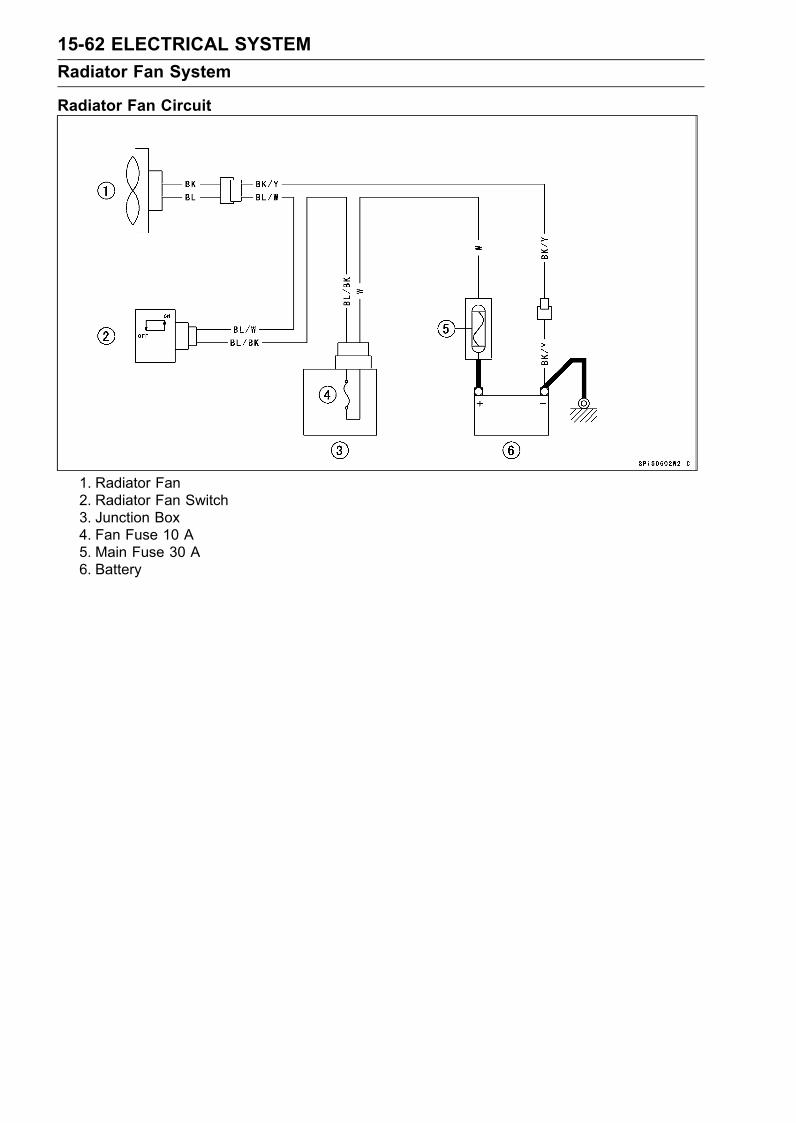
15-62 ELECTRICAL SYSTEMRadiator Fan System
Radiator Fan Circuit
1. Radiator Fan2. Radiator Fan Switch3. Junction Box4. Fan Fuse 10 A5. Main Fuse 30 A6. Battery
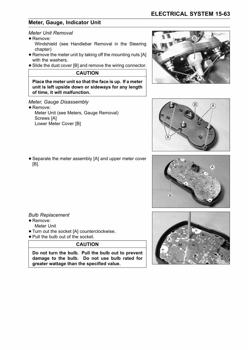
ELECTRICAL SYSTEM 15-63Meter, Gauge, Indicator Unit
Meter Unit Removal•Remove:Windshield (see Handlebar Removal in the Steeringchapter)•Remove the meter unit by taking off the mounting nuts [A]with the washers.• Slide the dust cover [B] and remove the wiring connector.
CAUTIONPlace the meter unit so that the face is up. If a meterunit is left upside down or sideways for any lengthof time, it will malfunction.
Meter, Gauge Disassembly•Remove:Meter Unit (see Meters, Gauge Removal)Screws [A]Lower Meter Cover [B]
• Separate the meter assembly [A] and upper meter cover[B].
Bulb Replacement•Remove:Meter Unit• Turn out the socket [A] counterclockwise.• Pull the bulb out of the socket.
CAUTIONDo not turn the bulb. Pull the bulb out to preventdamage to the bulb. Do not use bulb rated forgreater wattage than the specified value.
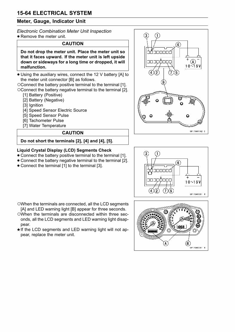
15-64 ELECTRICAL SYSTEMMeter, Gauge, Indicator Unit
Electronic Combination Meter Unit Inspection•Remove the meter unit.
CAUTIONDo not drop the meter unit. Place the meter unit sothat it faces upward. If the meter unit is left upsidedown or sideways for a long time or dropped, it willmalfunction.
•Using the auxiliary wires, connect the 12 V battery [A] tothe meter unit connector [B] as follows.Connect the battery positive terminal to the terminal [1].Connect the battery negative terminal to the terminal [2].[1] Battery (Positive)[2] Battery (Negative)[3] Ignition[4] Speed Sensor Electric Source[5] Speed Sensor Pulse[6] Tachometer Pulse[7] Water Temperature
CAUTIONDo not short the terminals [2], [4] and [4], [5].
Liquid Crystal Display (LCD) Segments Check•Connect the battery positive terminal to the terminal [1].• Connect the battery negative terminal to the terminal [2].• Connect the terminal [1] to the terminal [3].
When the terminals are connected, all the LCD segments[A] and LED warning light [B] appear for three seconds.When the terminals are disconnected within three sec-onds, all the LCD segments and LED warning light disap-pear.If the LCD segments and LED warning light will not ap-pear, replace the meter unit.
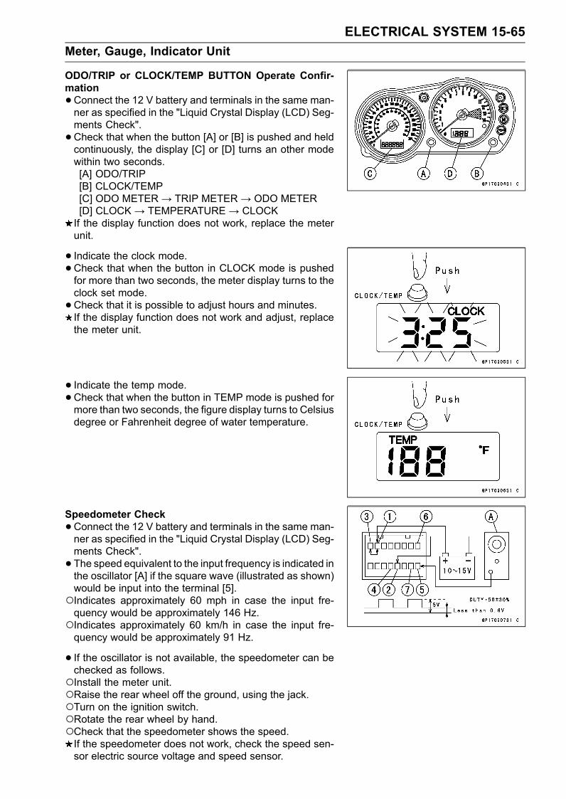
ELECTRICAL SYSTEM 15-65Meter, Gauge, Indicator Unit
ODO/TRIP or CLOCK/TEMP BUTTON Operate Confir-mation•Connect the 12 V battery and terminals in the same man-ner as specified in the "Liquid Crystal Display (LCD) Seg-ments Check".•Check that when the button [A] or [B] is pushed and heldcontinuously, the display [C] or [D] turns an other modewithin two seconds.[A] ODO/TRIP[B] CLOCK/TEMP[C] ODO METER→ TRIP METER→ ODO METER[D] CLOCK→ TEMPERATURE→ CLOCKIf the display function does not work, replace the meterunit.
• Indicate the clock mode.•Check that when the button in CLOCK mode is pushedfor more than two seconds, the meter display turns to theclock set mode.•Check that it is possible to adjust hours and minutes.If the display function does not work and adjust, replacethe meter unit.
• Indicate the temp mode.•Check that when the button in TEMP mode is pushed formore than two seconds, the figure display turns to Celsiusdegree or Fahrenheit degree of water temperature.
Speedometer Check•Connect the 12 V battery and terminals in the same man-ner as specified in the "Liquid Crystal Display (LCD) Seg-ments Check".• The speed equivalent to the input frequency is indicated inthe oscillator [A] if the square wave (illustrated as shown)would be input into the terminal [5].Indicates approximately 60 mph in case the input fre-quency would be approximately 146 Hz.Indicates approximately 60 km/h in case the input fre-quency would be approximately 91 Hz.
• If the oscillator is not available, the speedometer can bechecked as follows.Install the meter unit.Raise the rear wheel off the ground, using the jack.Turn on the ignition switch.Rotate the rear wheel by hand.Check that the speedometer shows the speed.If the speedometer does not work, check the speed sen-sor electric source voltage and speed sensor.
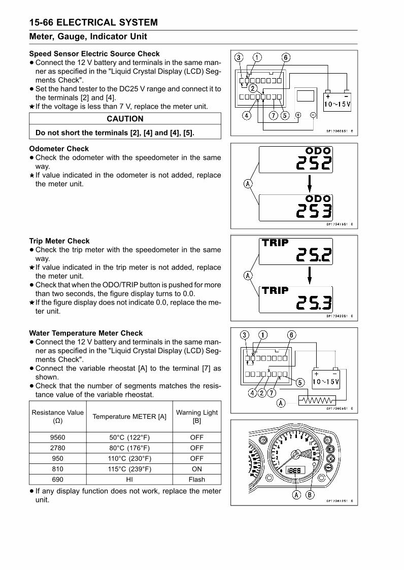
15-66 ELECTRICAL SYSTEMMeter, Gauge, Indicator Unit
Speed Sensor Electric Source Check•Connect the 12 V battery and terminals in the same man-ner as specified in the "Liquid Crystal Display (LCD) Seg-ments Check".• Set the hand tester to the DC25 V range and connect it tothe terminals [2] and [4].If the voltage is less than 7 V, replace the meter unit.
CAUTIONDo not short the terminals [2], [4] and [4], [5].
Odometer Check•Check the odometer with the speedometer in the sameway.If value indicated in the odometer is not added, replacethe meter unit.
Trip Meter Check•Check the trip meter with the speedometer in the sameway.If value indicated in the trip meter is not added, replacethe meter unit.• Check that when theODO/TRIP button is pushed formorethan two seconds, the figure display turns to 0.0.If the figure display does not indicate 0.0, replace the me-ter unit.
Water Temperature Meter Check•Connect the 12 V battery and terminals in the same man-ner as specified in the "Liquid Crystal Display (LCD) Seg-ments Check".•Connect the variable rheostat [A] to the terminal [7] asshown.•Check that the number of segments matches the resis-tance value of the variable rheostat.
Resistance Value(Ω) Temperature METER [A] Warning Light
[B]
9560 50°C (122°F) OFF2780 80°C (176°F) OFF950 110°C (230°F) OFF810 115°C (239°F) ON690 HI Flash
• If any display function does not work, replace the meterunit.
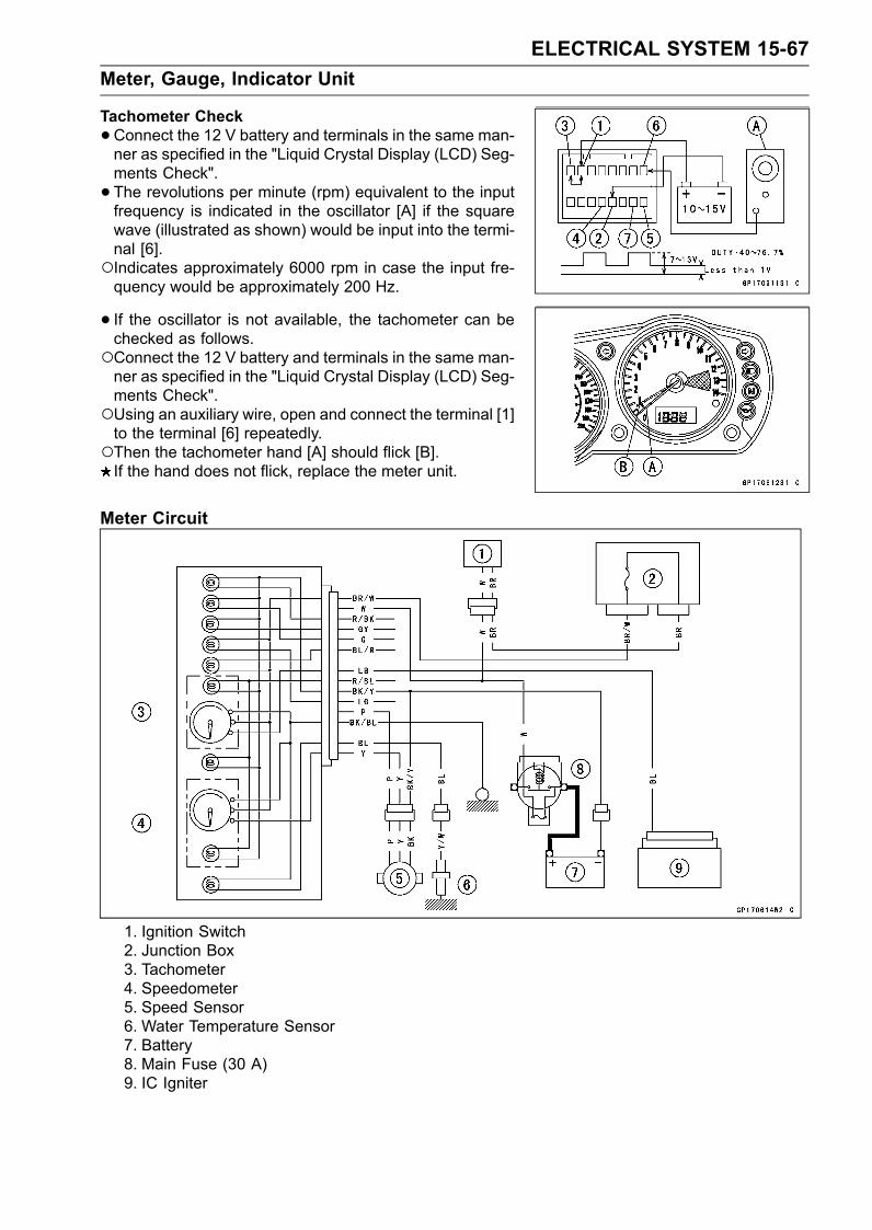
ELECTRICAL SYSTEM 15-67Meter, Gauge, Indicator Unit
Tachometer Check•Connect the 12 V battery and terminals in the same man-ner as specified in the "Liquid Crystal Display (LCD) Seg-ments Check".• The revolutions per minute (rpm) equivalent to the inputfrequency is indicated in the oscillator [A] if the squarewave (illustrated as shown) would be input into the termi-nal [6].Indicates approximately 6000 rpm in case the input fre-quency would be approximately 200 Hz.
• If the oscillator is not available, the tachometer can bechecked as follows.Connect the 12 V battery and terminals in the same man-ner as specified in the "Liquid Crystal Display (LCD) Seg-ments Check".Using an auxiliary wire, open and connect the terminal [1]to the terminal [6] repeatedly.Then the tachometer hand [A] should flick [B].If the hand does not flick, replace the meter unit.
Meter Circuit
1. Ignition Switch2. Junction Box3. Tachometer4. Speedometer5. Speed Sensor6. Water Temperature Sensor7. Battery8. Main Fuse (30 A)9. IC Igniter
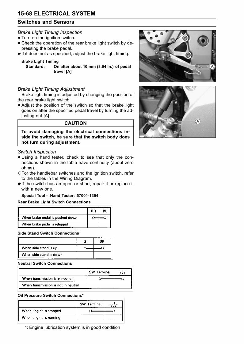
15-68 ELECTRICAL SYSTEMSwitches and Sensors
Brake Light Timing Inspection•Turn on the ignition switch.•Check the operation of the rear brake light switch by de-pressing the brake pedal.If it does not as specified, adjust the brake light timing.
Brake Light TimingStandard: On after about 10 mm (3.94 in.) of pedal
travel [A]
Brake Light Timing AdjustmentBrake light timing is adjusted by changing the position of
the rear brake light switch.• Adjust the position of the switch so that the brake lightgoes on after the specified pedal travel by turning the ad-justing nut [A].
CAUTIONTo avoid damaging the electrical connections in-side the switch, be sure that the switch body doesnot turn during adjustment.
Switch Inspection•Using a hand tester, check to see that only the con-nections shown in the table have continuity (about zeroohms).For the handlebar switches and the ignition switch, referto the tables in the Wiring Diagram.If the switch has an open or short, repair it or replace itwith a new one.Special Tool - Hand Tester: 57001-1394
Rear Brake Light Switch Connections
Side Stand Switch Connections
Neutral Switch Connections
Oil Pressure Switch Connections*
*: Engine lubrication system is in good condition
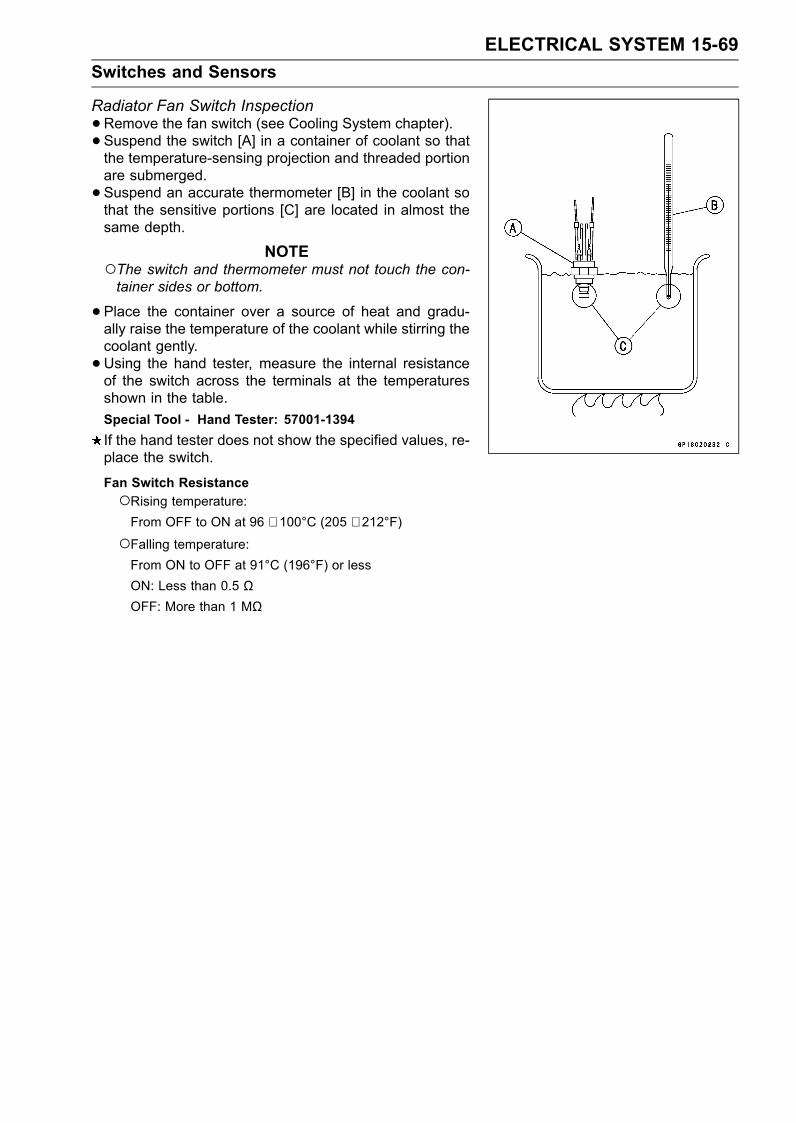
ELECTRICAL SYSTEM 15-69Switches and Sensors
Radiator Fan Switch Inspection•Remove the fan switch (see Cooling System chapter).• Suspend the switch [A] in a container of coolant so thatthe temperature-sensing projection and threaded portionare submerged.• Suspend an accurate thermometer [B] in the coolant sothat the sensitive portions [C] are located in almost thesame depth.
NOTEThe switch and thermometer must not touch the con-tainer sides or bottom.
•Place the container over a source of heat and gradu-ally raise the temperature of the coolant while stirring thecoolant gently.• Using the hand tester, measure the internal resistanceof the switch across the terminals at the temperaturesshown in the table.Special Tool - Hand Tester: 57001-1394If the hand tester does not show the specified values, re-place the switch.
Fan Switch ResistanceRising temperature:From OFF to ON at 96 ∼ 100°C (205 ∼ 212°F)
Falling temperature:From ON to OFF at 91°C (196°F) or lessON: Less than 0.5 ΩOFF: More than 1 MΩ
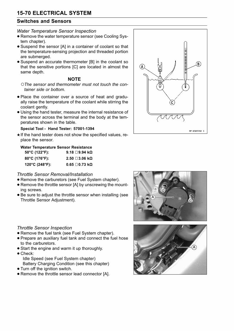
15-70 ELECTRICAL SYSTEMSwitches and Sensors
Water Temperature Sensor Inspection•Remove the water temperature sensor (see Cooling Sys-tem chapter).• Suspend the sensor [A] in a container of coolant so thatthe temperature-sensing projection and threaded portionare submerged.• Suspend an accurate thermometer [B] in the coolant sothat the sensitive portions [C] are located in almost thesame depth.
NOTEThe sensor and thermometer must not touch the con-tainer side or bottom.
•Place the container over a source of heat and gradu-ally raise the temperature of the coolant while stirring thecoolant gently.• Using the hand tester, measure the internal resistance ofthe sensor across the terminal and the body at the tem-peratures shown in the table.Special Tool - Hand Tester: 57001-1394If the hand tester does not show the specified values, re-place the sensor.
Water Temperature Sensor Resistance50°C (122°F): 9.18 ∼ 9.94 kΩ80°C (176°F): 2.50 ∼ 3.06 kΩ120°C (248°F): 0.65 ∼ 0.73 kΩ
Throttle Sensor Removal/Installation•Remove the carburetors (see Fuel System chapter).• Remove the throttle sensor [A] by unscrewing the mount-ing screws.• Be sure to adjust the throttle sensor when installing (seeThrottle Sensor Adjustment).
Throttle Sensor Inspection•Remove the fuel tank (see Fuel System chapter).• Prepare an auxiliary fuel tank and connect the fuel hoseto the carburetors.• Start the engine and warm it up thoroughly.•Check:Idle Speed (see Fuel System chapter)Battery Charging Condition (see this chapter)• Turn off the ignition switch.•Remove the throttle sensor lead connector [A].
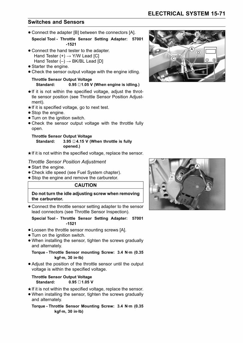
ELECTRICAL SYSTEM 15-71Switches and Sensors
•Connect the adapter [B] between the connectors [A].Special Tool - Throttle Sensor Setting Adapter: 57001
-1521
•Connect the hand tester to the adapter.Hand Tester (+) → Y/W Lead [C]Hand Tester (–) → BK/BL Lead [D]• Starter the engine.•Check the sensor output voltage with the engine idling.Throttle Sensor Output VoltageStandard: 0.95 ∼ 1.05 V (When engine is idling.)
If it is not within the specified voltage, adjust the throt-tle sensor position (see Throttle Sensor Position Adjust-ment).If it is specified voltage, go to next test.• Stop the engine.• Turn on the ignition switch.•Check the sensor output voltage with the throttle fullyopen.
Throttle Sensor Output VoltageStandard: 3.95 ∼ 4.15 V (When throttle is fully
opened.)
If it is not within the specified voltage, replace the sensor.
Throttle Sensor Position Adjustment•Start the engine.•Check idle speed (see Fuel System chapter).• Stop the engine and remove the carburetor.
CAUTIONDo not turn the idle adjusting screw when removingthe carburetor.
•Connect the throttle sensor setting adapter to the sensorlead connectors (see Throttle Sensor Inspection).Special Tool - Throttle Sensor Setting Adapter: 57001
-1521
• Loosen the throttle sensor mounting screws [A].• Turn on the ignition switch.•When installing the sensor, tighten the screws graduallyand alternately.Torque - Throttle Sensor mounting Screw: 3.4 N·m (0.35
kgf·m, 30 in·lb)
•Adjust the position of the throttle sensor until the outputvoltage is within the specified voltage.
Throttle Sensor Output VoltageStandard: 0.95 ∼ 1.05 V
If it is not within the specified voltage, replace the sensor.•When installing the sensor, tighten the screws graduallyand alternately.Torque - Throttle Sensor Mounting Screw: 3.4 N·m (0.35
kgf·m, 30 in·lb)
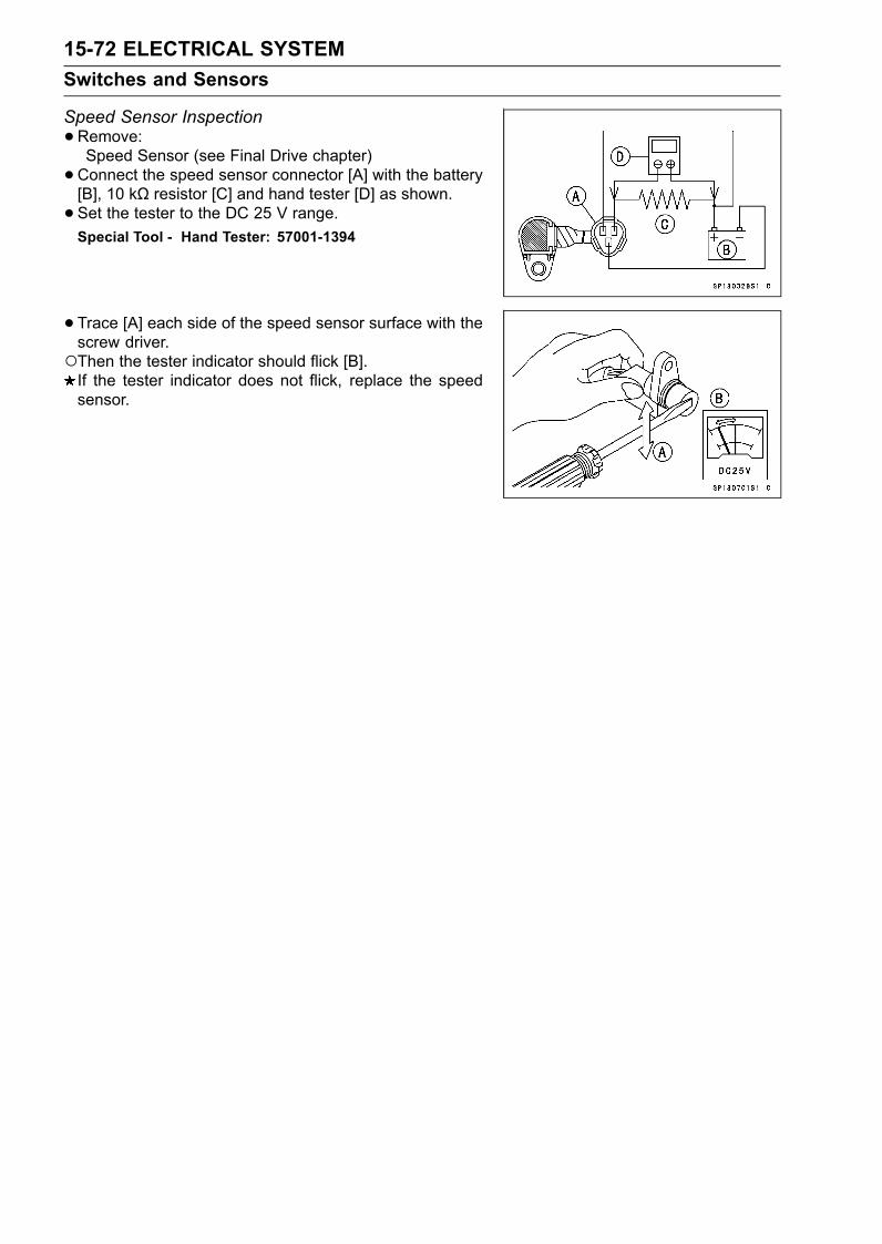
15-72 ELECTRICAL SYSTEMSwitches and Sensors
Speed Sensor Inspection•Remove:Speed Sensor (see Final Drive chapter)•Connect the speed sensor connector [A] with the battery[B], 10 kΩ resistor [C] and hand tester [D] as shown.• Set the tester to the DC 25 V range.Special Tool - Hand Tester: 57001-1394
•Trace [A] each side of the speed sensor surface with thescrew driver.Then the tester indicator should flick [B].If the tester indicator does not flick, replace the speedsensor.
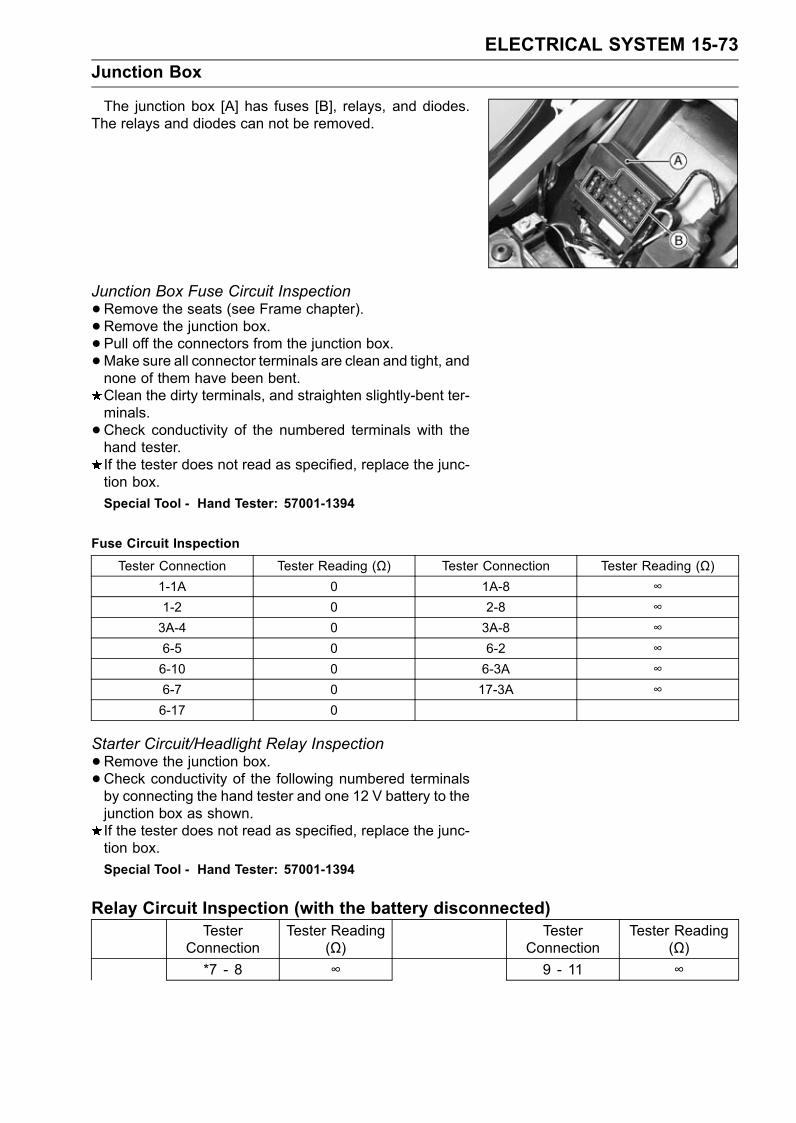
ELECTRICAL SYSTEM 15-73Junction Box
The junction box [A] has fuses [B], relays, and diodes.The relays and diodes can not be removed.
Junction Box Fuse Circuit Inspection•Remove the seats (see Frame chapter).• Remove the junction box.• Pull off the connectors from the junction box.•Make sure all connector terminals are clean and tight, andnone of them have been bent.Clean the dirty terminals, and straighten slightly-bent ter-minals.•Check conductivity of the numbered terminals with thehand tester.If the tester does not read as specified, replace the junc-tion box.Special Tool - Hand Tester: 57001-1394
Fuse Circuit InspectionTester Connection Tester Reading (Ω) Tester Connection Tester Reading (Ω)
1-1A 0 1A-8 ∞1-2 0 2-8 ∞3A-4 0 3A-8 ∞6-5 0 6-2 ∞6-10 0 6-3A ∞6-7 0 17-3A ∞6-17 0
Starter Circuit/Headlight Relay Inspection•Remove the junction box.•Check conductivity of the following numbered terminalsby connecting the hand tester and one 12 V battery to thejunction box as shown.If the tester does not read as specified, replace the junc-tion box.Special Tool - Hand Tester: 57001-1394
Relay Circuit Inspection (with the battery disconnected)Tester
ConnectionTester Reading
(Ω)Tester
ConnectionTester Reading
(Ω)*7 - 8 ∞ 9 - 11 ∞
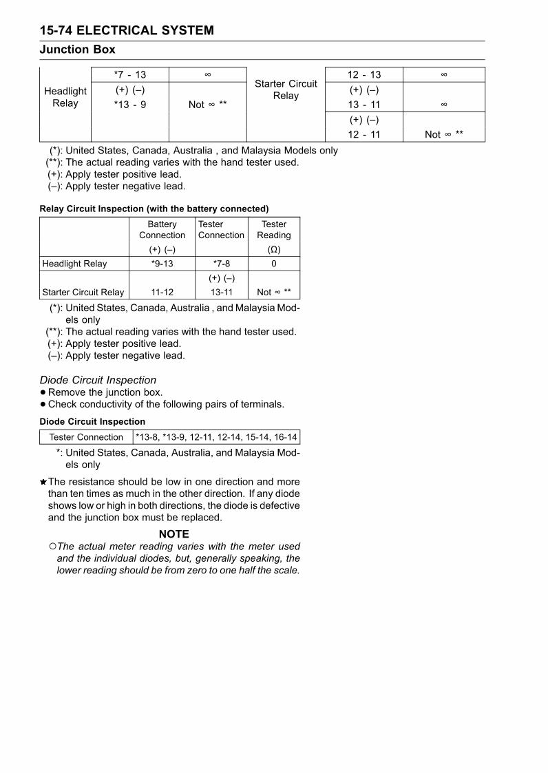
15-74 ELECTRICAL SYSTEMJunction Box
*7 - 13 ∞ 12 - 13 ∞(+) (–) (+) (–)*13 - 9 Not ∞ **
Starter CircuitRelay
13 - 11 ∞HeadlightRelay
(+) (–)12 - 11 Not ∞ **
(*): United States, Canada, Australia , and Malaysia Models only(**): The actual reading varies with the hand tester used.(+): Apply tester positive lead.(–): Apply tester negative lead.
Relay Circuit Inspection (with the battery connected)Battery
ConnectionTesterConnection
TesterReading
(+) (–) (Ω)Headlight Relay *9-13 *7-8 0
(+) (–)Starter Circuit Relay 11-12 13-11 Not ∞ **
(*): United States, Canada, Australia , andMalaysia Mod-els only
(**): The actual reading varies with the hand tester used.(+): Apply tester positive lead.(–): Apply tester negative lead.
Diode Circuit Inspection•Remove the junction box.•Check conductivity of the following pairs of terminals.Diode Circuit InspectionTester Connection *13-8, *13-9, 12-11, 12-14, 15-14, 16-14
*: United States, Canada, Australia, and Malaysia Mod-els only
The resistance should be low in one direction and morethan ten times as much in the other direction. If any diodeshows low or high in both directions, the diode is defectiveand the junction box must be replaced.
NOTEThe actual meter reading varies with the meter usedand the individual diodes, but, generally speaking, thelower reading should be from zero to one half the scale.
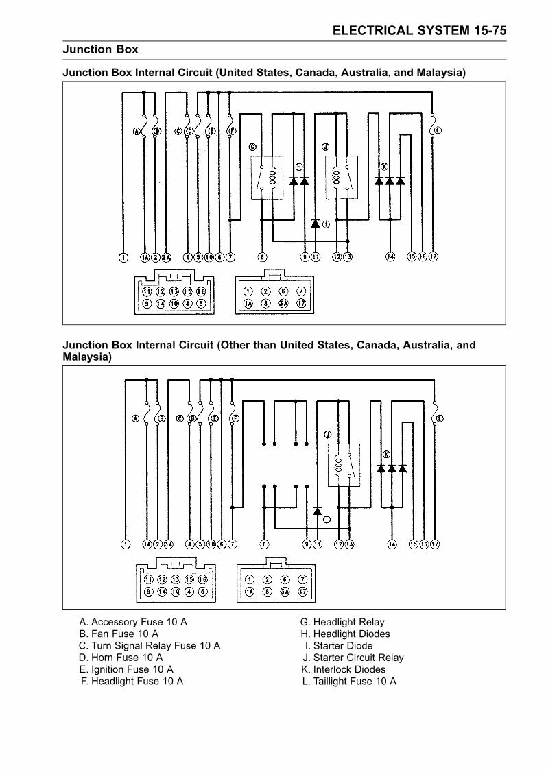
ELECTRICAL SYSTEM 15-75Junction Box
Junction Box Internal Circuit (United States, Canada, Australia, and Malaysia)
Junction Box Internal Circuit (Other than United States, Canada, Australia, andMalaysia)
A. Accessory Fuse 10 AB. Fan Fuse 10 AC. Turn Signal Relay Fuse 10 AD. Horn Fuse 10 AE. Ignition Fuse 10 AF. Headlight Fuse 10 A
G. Headlight RelayH. Headlight DiodesI. Starter DiodeJ. Starter Circuit RelayK. Interlock DiodesL. Taillight Fuse 10 A
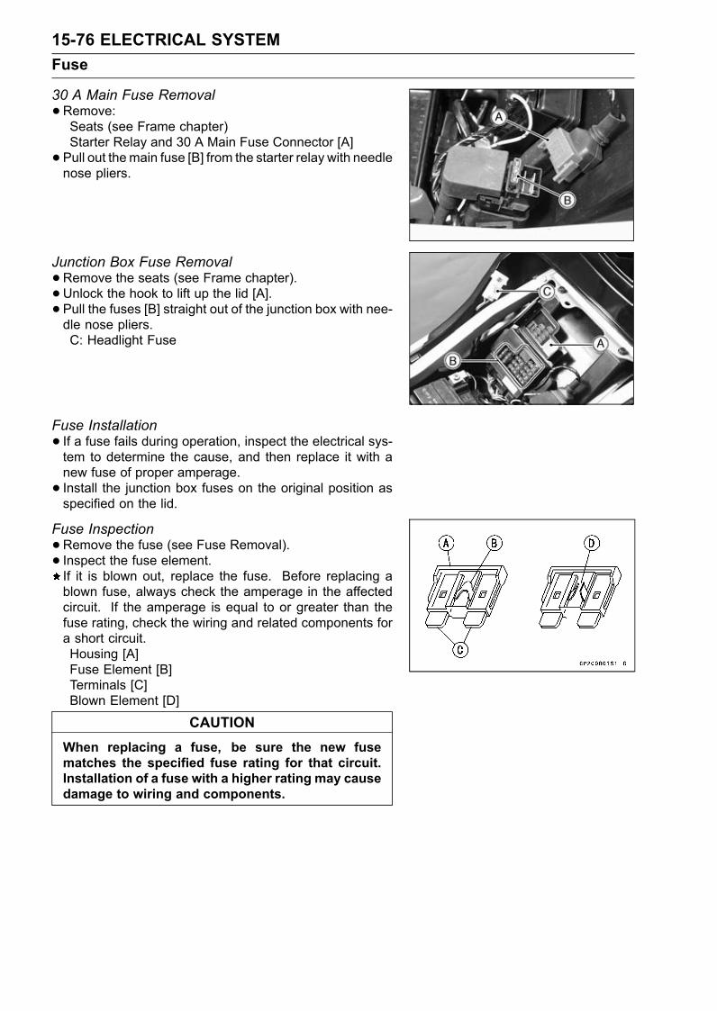
15-76 ELECTRICAL SYSTEMFuse
30 A Main Fuse Removal•Remove:Seats (see Frame chapter)Starter Relay and 30 A Main Fuse Connector [A]• Pull out themain fuse [B] from the starter relay with needlenose pliers.
Junction Box Fuse Removal•Remove the seats (see Frame chapter).• Unlock the hook to lift up the lid [A].• Pull the fuses [B] straight out of the junction box with nee-dle nose pliers.C: Headlight Fuse
Fuse Installation• If a fuse fails during operation, inspect the electrical sys-tem to determine the cause, and then replace it with anew fuse of proper amperage.• Install the junction box fuses on the original position asspecified on the lid.
Fuse Inspection•Remove the fuse (see Fuse Removal).• Inspect the fuse element.If it is blown out, replace the fuse. Before replacing ablown fuse, always check the amperage in the affectedcircuit. If the amperage is equal to or greater than thefuse rating, check the wiring and related components fora short circuit.Housing [A]Fuse Element [B]Terminals [C]Blown Element [D]
CAUTIONWhen replacing a fuse, be sure the new fusematches the specified fuse rating for that circuit.Installation of a fuse with a higher rating may causedamage to wiring and components.
APPENDIX 16-1
16
AppendixTable of Contents
Troubleshooting Guide ........................................................................................................... 16-2General Lubrication ................................................................................................................ 16-7
Lubrication ....................................................................................................................... 16-7Nut, Bolt, and Fastener Tightness .......................................................................................... 16-8
Tightness Inspection ......................................................................................................... 16-8Unit Conversion Table ............................................................................................................ 16-9
16-2 APPENDIXTroubleshooting Guide
NOTEThis is not an exhaustive list, giving everypossible cause for each problem listed. Itis meant simply as a rough guide to assistthe troubleshooting for some of the morecommon difficulties.
Engine Doesn’t Start, StartingDifficulty:Starter motor not rotating:Starter lockout switch or neutral switch trou-ble
Starter motor troubleBattery voltage lowStarter relays not contacting or operatingStarter button not contactingWiring open or shortedIgnition switch troubleEngine stop switch troubleFuse blown
Starter motor rotating but engine doesn’tturn over:Starter clutch trouble
Engine won’t turn over:Valve seizureValve lifter seizureCylinder, piston seizureCrankshaft seizureConnecting rod small end seizureConnecting rod big end seizureTransmission gear or bearing seizureCamshaft seizureStarter idle gear seizure
No fuel flow:No fuel in tankBattery voltage lowFuel pump troubleFuel pump relay troubleFuel tank air vent obstructedFuel filter cloggedFuel tap cloggedFuel line cloggedFloat valve cloggedFuel cut valve left close (check fuel cutvalve and IC igniter)
Engine flooded:Fuel level in carburetor float bowl too highFloat valve worn or stuck openStarting technique faulty(When flooded, crank the engine with thethrottle fully opened to allow more air toreach the engine.)
No spark; spark weak:Battery voltage lowSpark plug dirty, broken, or maladjustedSpark plug cap or high tension wiring trou-ble
Spark plug cap shorted or not in good con-tact
Spark plug incorrectIC igniter troubleCam sensor troubleNeutral, starter lockout, or sidestand switchtrouble
Crankshaft sensor troubleStick coil troubleIgnition or engine stop switch shortedWiring shorted or openFuse blown
Fuel/air mixture incorrect:Pilot screw and/or idle adjusting screw mal-adjusted
Pilot jet, or air passage cloggedAir cleaner clogged, poorly sealed, or miss-ing
Starter jet cloggedCompression Low:Spark plug looseCylinder head not sufficiently tighteneddown
No valve clearanceCylinder, piston wornPiston ring bad (worn, weak, broken, orsticking)
Piston ring/groove clearance excessiveCylinder head gasket damagedCylinder head warpedValve spring broken or weakValve not seating properly (valve bent,worn, or carbon accumulation on theseating surface)
Poor Running at Low Speed:Spark weak:Battery voltage lowSpark plug dirty, broken, or maladjustedStick coil wiring troubleStick coil not in good contactSpark plug incorrectIC igniter troubleCrankshaft sensor troubleStick coil trouble
Fuel/air mixture incorrect:Pilot screw maladjustedPilot jet, or air passage cloggedAir bleed pipe bleed holes cloggedPilot passage cloggedAir cleaner clogged, poorly sealed, or miss-ing
Choke plunger stuck openFuel level in carburetor float bowl too highor too low
Fuel tank air vent obstructed
APPENDIX 16-3Troubleshooting Guide
Fuel cut valve won’t fully open (check fuelcut valve and IC igniter)
Carburetor holder looseAir cleaner duct looseAir cleaner O-ring damagedFuel pump troubleFuel pump relay troubleFuel filter clogged
Compression low:Spark plug looseCylinder head not sufficiently tighteneddown
No valve clearanceCylinder, piston wornPiston ring bad (worn, weak, broken, orsticking)
Piston ring/groove clearance excessiveCylinder head warpedCylinder head gasket damagedValve spring broken or weakValve not seating properly (valve bent,worn, or carbon accumulation on theseating surface)
Other:IC igniter troubleCarburetor not synchronizingCarburetor vacuum piston doesn’t slidesmoothly
Carburetor vacuum piston diaphragm dam-age
Engine oil viscosity too highDrive train troubleBrake draggingAir suction valve troubleVacuum switch valve trouble
Poor Running or No Power at HighSpeed:Firing incorrect:Spark plug dirty, broken, or maladjustedStick coil wiring troubleStick coil not in good contactSpark plug incorrectIC igniter troubleCrankshaft sensor troubleStick coil trouble
Fuel/air mixture incorrect:Choke plunger stuck openMain jet clogged or wrong sizeJet needle or needle jet wornAir jet cloggedFuel level in carburetor float bowl too highor too low
Fuel cut valve won’t fully open (check fuelcut valve)
Bleed holes of needle jet holder or needlejet clogged
Air cleaner clogged, poorly sealed, or miss-ing
Air cleaner duct looseAir cleaner O-ring damagedWater or foreign matter in fuelCarburetor holder looseFuel to carburetor insufficientFuel tank air vent obstructedFuel tap cloggedFuel line cloggedFuel pump troubleFuel pump relay troubleFuel filter clogged
Compression low:Spark plug looseCylinder head not sufficiently tighteneddown
No valve clearanceCylinder, piston wornPiston ring bad (worn, weak, broken, orsticking)
Piston ring/groove clearance excessiveCylinder head gasket damagedCylinder head warpedValve spring broken or weakValve not seating properly (valve bent,worn, or carbon accumulation on theseating surface.)
Knocking:Carbon built up in combustion chamberFuel poor quality or incorrectSpark plug incorrectIC igniter trouble
Miscellaneous:Throttle valve won’t fully openCarburetor vacuum piston doesn’t slidesmoothly
Carburetor vacuum piston diaphragm dam-aged
Brake draggingClutch slippingOverheatingEngine oil level too highEngine oil viscosity too highDrive train troubleAir suction valve troubleVacuum switch valve troubleCatalytic converters melt down due to muf-fler overheating (KLEEN)
Overheating:Firing incorrect:Spark plug dirty, broken, or maladjustedSpark plug incorrectIC Igniter trouble

16-4 APPENDIXTroubleshooting Guide
Muffler overheating:For KLEEN, do not run the engine even ifwith only one cylinder misfiring or poorrunning (Request the nearest service fa-cility to correct it)
For KLEEN, do not push-start with a deadbattery (Connect another full-chargedbattery with jumper cables, and start theengine using the electric starter)
For KLEEN, do not start the engine undermisfire due to spark plug fouling or poorconnection of the stick coil
For KLEEN, do not coast the motorcyclewith the ignition switch off (Turn the igni-tion switch ON and run the engine)
IC igniter or fuel cut valve troubleIC igniter trouble
Fuel/air mixture incorrect:Main jet clogged or wrong sizeFuel level in carburetor float bowl too lowCarburetor holder looseAir cleaner duct looseAir cleaner poorly sealed, or missingAir cleaner O-ring damagedAir cleaner cloggedFuel pump troubleFuel pump relay troubleFuel filter clogged
Compression high:Carbon built up in combustion chamber
Engine load faulty:Clutch slippingEngine oil level too highEngine oil viscosity too highDrive train troubleBrake dragging
Lubrication inadequate:Engine oil level too lowEngine oil poor quality or incorrect
Oil cooler incorrect:Oil cooler clogged
Gauge incorrect:Water temperature meter brokenWater temperature sensor broken
Coolant incorrect:Coolant level too lowCoolant deteriorated
Cooling system component incorrect:Radiator fin damagedRadiator cloggedThermostat troubleRadiator cap troubleRadiator fan switch troubleFan motor brokenFan blade damagedWater pump not turningWater pump impeller damaged
Over Cooling:Gauge incorrect:Water temperature meter brokenWater temperature sensor broken
Cooling system component incorrect:Radiator fan switch troubleThermostat trouble
Clutch Operation Faulty:Clutch slipping:Friction plate worn or warpedSteel plate worn or warpedClutch spring broken or weakClutch hub or housing unevenly wornNo clutch lever playClutch inner cable troubleClutch release mechanism trouble
Clutch not disengaging properly:Clutch plate warped or too roughClutch spring compression unevenEngine oil deterioratedEngine oil viscosity too highEngine oil level too highClutch housing frozen on drive shaftClutch hub nut looseClutch hub spline damagedClutch friction plate installed wrongClutch lever play excessiveClutch release mechanism trouble
Gear Shifting Faulty:Doesn’t go into gear; shift pedal doesn’treturn:Clutch not disengagingShift fork bent or seizedGear stuck on the shaftGear positioning lever bindingShift return spring weak or brokenShift return spring pin looseShift mechanism arm spring brokenShift mechanism arm brokenShift pawl broken
Jumps out of gear:Shift fork ear worn, bentGear groove wornGear dogs and/or dog holes wornShift drum groove wornGear positioning lever spring weak or bro-ken
Shift fork guide pin wornDrive shaft, output shaft, and/or gearsplines worn
Overshifts:Gear positioning lever spring weak or bro-ken
Shift mechanism arm spring broken
APPENDIX 16-5Troubleshooting Guide
Abnormal Engine Noise:Knocking:IC igniter troubleCarbon built up in combustion chamberFuel poor quality or incorrectSpark plug incorrectOverheating
Piston slap:Cylinder/piston clearance excessiveCylinder, piston wornConnecting rod bentPiston pin, piston pin hole worn
Valve noise:Valve clearance incorrectValve spring broken or weakCamshaft bearing wornValve lifter worn
Other noise:Connecting rod small end clearance exces-sive
Connecting rod big end clearance exces-sive
Piston ring/groove clearance excessivePiston ring worn, broken, or stuckPiston ring groove wornPiston seizure, damageCylinder head gasket leakingExhaust pipe leaking at cylinder head con-nection
Crankshaft runout excessiveEngine mounts looseCrankshaft bearing wornPrimary gear worn or chippedCamshaft chain tensioner troubleCamshaft chain, sprocket, guide wornAir suction valve damagedVacuum switch valve damagedAlternator rotor looseCatalytic converters melt down due to muf-fler overheating (KLEEN)
Abnormal Drive Train Noise:Clutch noise:Clutch rubber damper weak or damagedClutch housing/friction plate clearance ex-cessive
Clutch housing gear wornTransmission noise:Bearings wornTransmission gears worn or chippedMetal chips jammed in gear teethEngine oil insufficient
Drive line noise:Drive chain adjusted improperlyDrive chain wornRear and/or engine sprocket wornChain lubrication insufficient
Rear wheel misaligned
Abnormal Frame Noise:Front fork noise:Oil insufficient or too thinSpring weak or broken
Rear shock absorber noise:Shock absorber damaged
Disc brake noise:Pad installed incorrectlyPad surface glazedDisc warpedCaliper trouble
Other noise:Bracket, nut, bolt, etc. not properlymounted or tightened
Oil Pressure Warning Light Goes On:Engine oil pump damagedEngine oil screen cloggedEngine oil level too lowEngine oil viscosity too lowCamshaft bearing wornCrankshaft bearings wornOil pressure switch damagedWiring faultyRelief valve stuck openO-ring at the oil passage in the crankcasedamaged
Exhaust Smokes Excessively:White smoke:Piston oil ring wornCylinder wornValve oil seal damagedValve guide wornEngine oil level too high
Black smoke:Air cleaner cloggedMain jet too large or fallen offStarter plunger stuck openFuel level in carburetor float bowl too high
Brown smoke:Main jet too smallFuel level in carburetor float bowl too lowAir cleaner duct looseAir cleaner O-ring damagedAir cleaner poorly sealed or missing
Handling and/or StabilityUnsatisfactory:Handlebar hard to turn:Cable routing incorrectHose routing incorrectWiring routing incorrectSteering stem locknut too tight
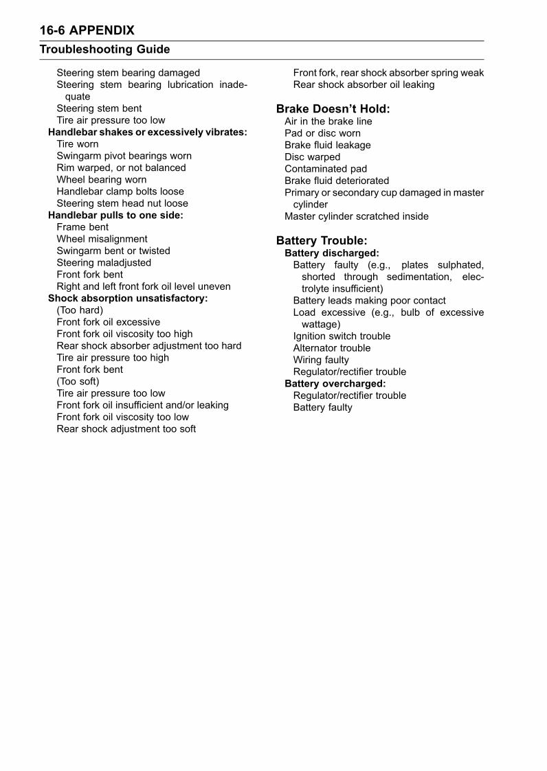
16-6 APPENDIXTroubleshooting Guide
Steering stem bearing damagedSteering stem bearing lubrication inade-quate
Steering stem bentTire air pressure too low
Handlebar shakes or excessively vibrates:Tire wornSwingarm pivot bearings wornRim warped, or not balancedWheel bearing wornHandlebar clamp bolts looseSteering stem head nut loose
Handlebar pulls to one side:Frame bentWheel misalignmentSwingarm bent or twistedSteering maladjustedFront fork bentRight and left front fork oil level uneven
Shock absorption unsatisfactory:(Too hard)Front fork oil excessiveFront fork oil viscosity too highRear shock absorber adjustment too hardTire air pressure too highFront fork bent(Too soft)Tire air pressure too lowFront fork oil insufficient and/or leakingFront fork oil viscosity too lowRear shock adjustment too soft
Front fork, rear shock absorber spring weakRear shock absorber oil leaking
Brake Doesn’t Hold:Air in the brake linePad or disc wornBrake fluid leakageDisc warpedContaminated padBrake fluid deterioratedPrimary or secondary cup damaged in mastercylinder
Master cylinder scratched inside
Battery Trouble:Battery discharged:Battery faulty (e.g., plates sulphated,shorted through sedimentation, elec-trolyte insufficient)
Battery leads making poor contactLoad excessive (e.g., bulb of excessivewattage)
Ignition switch troubleAlternator troubleWiring faultyRegulator/rectifier trouble
Battery overcharged:Regulator/rectifier troubleBattery faulty
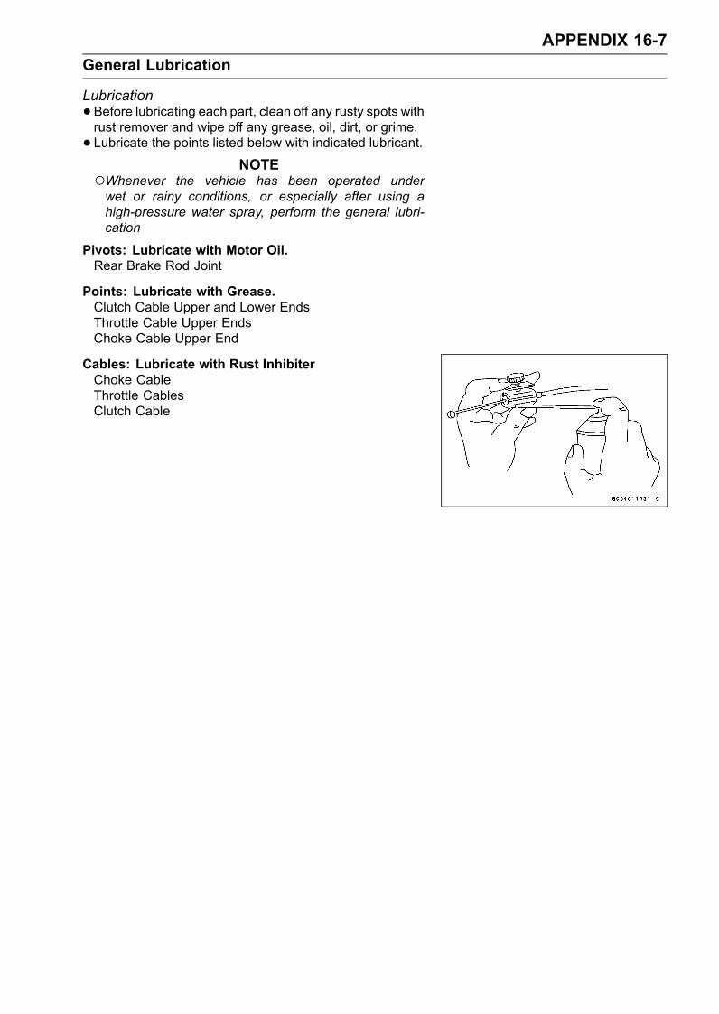
APPENDIX 16-7General Lubrication
Lubrication•Before lubricating each part, clean off any rusty spots withrust remover and wipe off any grease, oil, dirt, or grime.• Lubricate the points listed below with indicated lubricant.
NOTEWhenever the vehicle has been operated underwet or rainy conditions, or especially after using ahigh-pressure water spray, perform the general lubri-cation
Pivots: Lubricate with Motor Oil.Rear Brake Rod Joint
Points: Lubricate with Grease.Clutch Cable Upper and Lower EndsThrottle Cable Upper EndsChoke Cable Upper End
Cables: Lubricate with Rust InhibiterChoke CableThrottle CablesClutch Cable
16-8 APPENDIXNut, Bolt, and Fastener Tightness
Tightness Inspection•Check the tightness of the bolts and nuts listed here. Also,check to see that each cotter pin is in place and in goodcondition.
NOTEFor the engine fasteners, check the tightness of themwhen the engine is cold (at room temperature).
If there are loose fasteners, retorque them to the spec-ified torque following the specified tightening sequence.Refer to the appropriate chapter for torque specifications.If torque specifications are not in the appropriate chapter,see the Standard Torque Table. For each fastener, firstloosen it by 1/2 turn, then tighten it.If cotter pins are damaged, replace them with new ones.
Nut, Bolt and Fastener to be checkedWheels:Front Axle NutFront Axle Clamp BoltRear Axle NutRear Axle Nut Cotter Pin
Brakes:Front Master Cylinder Clamp BoltsCaliper Mounting BoltsRear Master Cylinder Mounting BoltsBrake Lever Pivot NutBrake Pedal BoltBrake Rod Joint Cotter Pin
Suspension:Front Fork Clamp BoltsRear Shock Absorber Mounting NutsSwingarm Pivot Shaft NutUni-Trak Link Nuts
Steering:Steering Stem Head NutHandlebar Mounting Bolts
Engine:Engine Mounting BoltsExhaust Pipe Mounting BoltMuffler Mounting NutExhaust Pipe Holder NutsMuffler Body and Exhaust Pipe Connecting BoltsClutch Lever Pivot Nut
Others:Sidestand Mounting BoltFootpeg Mounting BoltsFootpeg Bracket Mounting BoltsFront Fender Mounting Bolts
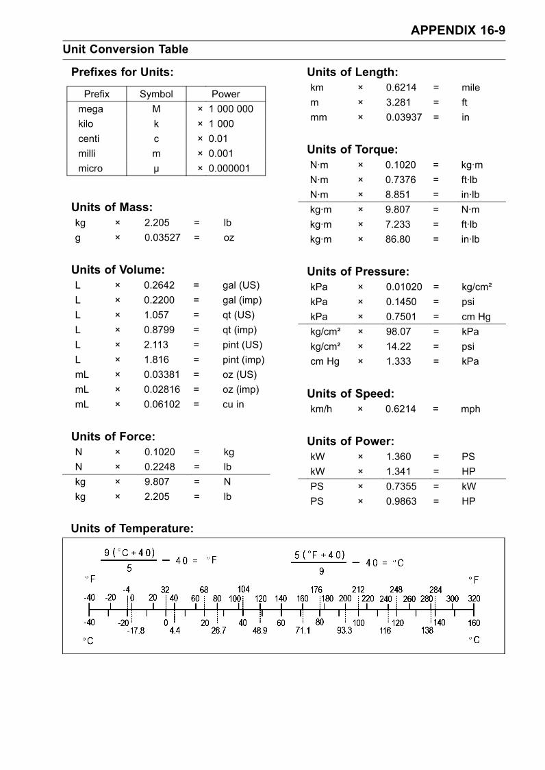
APPENDIX 16-9Unit Conversion Table
Prefixes for Units:
Prefix Symbol Powermega M × 1 000 000kilo k × 1 000centi c × 0.01milli m × 0.001micro µ × 0.000001
Units of Mass:kg × 2.205 = lbg × 0.03527 = oz
Units of Volume:L × 0.2642 = gal (US)L × 0.2200 = gal (imp)L × 1.057 = qt (US)L × 0.8799 = qt (imp)L × 2.113 = pint (US)L × 1.816 = pint (imp)mL × 0.03381 = oz (US)mL × 0.02816 = oz (imp)mL × 0.06102 = cu in
Units of Force:N × 0.1020 = kgN × 0.2248 = lbkg × 9.807 = Nkg × 2.205 = lb
Units of Length:km × 0.6214 = milem × 3.281 = ftmm × 0.03937 = in
Units of Torque:N·m × 0.1020 = kg·mN·m × 0.7376 = ft·lbN·m × 8.851 = in·lbkg·m × 9.807 = N·mkg·m × 7.233 = ft·lbkg·m × 86.80 = in·lb
Units of Pressure:kPa × 0.01020 = kg/cm²kPa × 0.1450 = psikPa × 0.7501 = cm Hgkg/cm² × 98.07 = kPakg/cm² × 14.22 = psicm Hg × 1.333 = kPa
Units of Speed:km/h × 0.6214 = mph
Units of Power:kW × 1.360 = PSkW × 1.341 = HPPS × 0.7355 = kWPS × 0.9863 = HP
Units of Temperature:
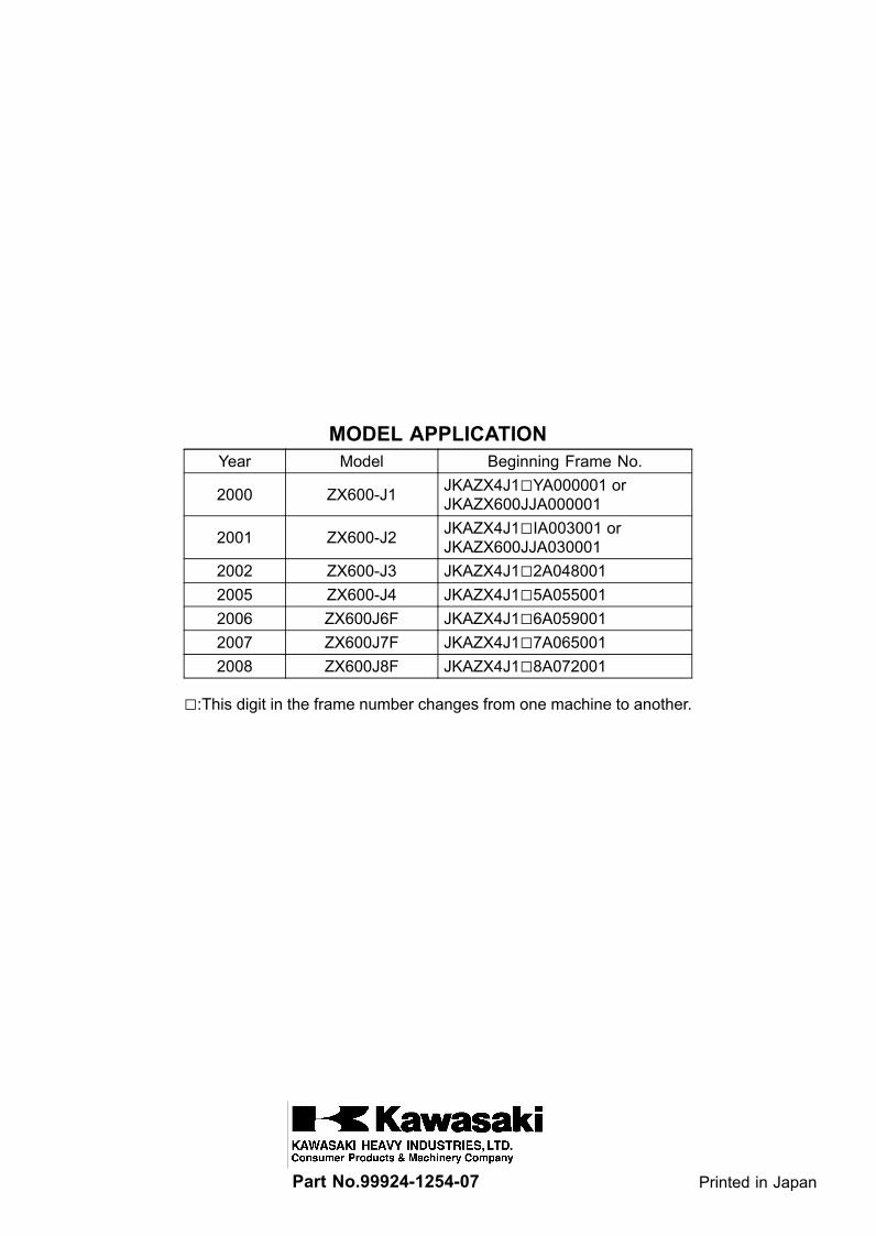
MODEL APPLICATIONYear Model Beginning Frame No.
2000 ZX600-J1 JKAZX4J1YA000001 orJKAZX600JJA000001
2001 ZX600-J2 JKAZX4J1IA003001 orJKAZX600JJA030001
2002 ZX600-J3 JKAZX4J12A0480012005 ZX600-J4 JKAZX4J15A0550012006 ZX600J6F JKAZX4J16A0590012007 ZX600J7F JKAZX4J17A0650012008 ZX600J8F JKAZX4J18A072001
:This digit in the frame number changes from one machine to another.
Part No.99924-1254-07 Printed in Japan