Embed Size (px)
Citation preview

263
Motorcycles and Sidecars 5. POWER TRANSMISSION
CHAPTER V. Power Transmission System Parts.Utility of Clutch Defined -Theory of Friction Clutch Action -Types of Clutches -Materials Employed in Clutches -Clutch Location -Typical Motorcycle Clutches -Why Change Speed Gearing is Desirable -Value of Variable Speed Gearing -Variable Speeds by Slipping Clutch -Change Speed Gear Location -Variable Speed Pulleys -Engine Shaft Gear -Countershaft Gears -Sliding Gear Type -Power Transmission Methods -Belt Drive Systems -Types of Belts -Standard Belt Forms -Advantages of Drive by Chains -Single Chain Direct Drive -Double Chain Drive -Types of Driving Chains -Combination Chain and Belt Drive -Bevel and Worm Gear Final Drive -Relation of Engine Power to Gear Ratio 285-371
The power transmission group is next in impor-tance to the energy producing elements andmuch depends upon correct application of thevarious devices utilized in transmitting the engineenergy to the traction member. The efficiency ofthe motorcycle as a whole depends largely on thatof the power transmission system. An extremelypowerful and effective motor is of little avail if alarge proportion of the power it produces is con-sumed by friction or transmission losses before itcan be applied to the rear wheel to produce use-ful work.
The principal elements of the transmission sys-tem of a simple motorcycle are first, a clutchingdevice that permits of releasing the engine fromthe driving medium or applying the power at will,and second, some system of transmitting theengine power from the clutch to the rear wheels.Many of the 1914 motorcycles include still anoth-er element, the variable speed gear, in the powertransmission system.

264
Motorcycles and Sidecars 5. POWER TRANSMISSION
Utility of Clutch DefinedPractically every motorcycleproduced at the present time isfitted with a free engine andclutching device that will permitof running the engine withoutdriving the vehicle. In the earlydays of motorcycle development,the drive was direct from theengine crankshaft to the rearwheels without any, engine re-leasing device.
It was necessary to start allmotorcycles by a preliminarypedaling process which meantthat the entire machine had tobe pushed along briskly regard-less of character of road surfaceor gradients so the motor wouldbe turned sufficiently fast tostart. It was not possible to putthe machine on a stand, as isdone at the present time, be-cause the absence of the freeengine device made it imperativethat the machine should acquirea certain amount of momentumbefore the power was applied.
The result was that it required avery strong person to start a power-ful twin-cylinder motor fitted to a
heavy machine, because, while themachine might start in ten feet, itmight require vigorous pedaling forhalf a city block before the enginewas started. When the engine didstart, it was apt to race or take holdsuddenly because very often thespark would be well advanced orthe throttle would be opened tosecure easy starting.
The sudden application of powerwas not favorable to the powertransmission system andsnapped chains or broken beltswere not an uncommon resultwhen the power was suddenlyapplied in this manner.
When a free engine clutch isemployed, it is possible to placethe machine on a stand andstart the power plant with com-parative ease because the onlyresistance to overcome is thatoffered by the motor itself in-stead of the rider having to fur-nish the power to move theheavy machine along the road.
After the engine is started, it ispossible to release the clutchand disconnect the power fromthe rear wheels. This enables
the rider to take the machine offthe stand, keep the engine run-ning, and start off very gradual-ly by utilizing the power of themotor which is delivered to therear wheel in gradually increas-ing increments if the frictionclutch is let in slowly.
Another advantage of the clutchis that it permits of ready con-trol under unfavorable ridingconditions such as in traffic,climbing hills, or overcomingpoor highway surfaces.
Instead of controlling the ma-chine by continually interruptingthe motor action, as was the casein the old direct drive days, atwist of the grip on the handle baror an easy movement of a conve-niently placed lever will releasethe clutch, interrupt the driveand permit the rider to bring hismachine to a stand-still, if neces-sary, without stopping the motor.
The control of modern machinesis very similar to that of an au-tomobile, and is such an im-provement over the old systemthat its importance is not apt tobe realized except by those of us

265
Motorcycles and Sidecars 5. POWER TRANSMISSION
whose experience dates back farenough so we can qualify asveteran motorcyclists.
With the old forms of machines,when a patch of sand was en-countered or a gradient that didnot permit one to “rush” the hillby putting on full speed beforereaching the bottom and dependlargely on momentum to assistin overcoming the resistance, itwas necessary to either get offand push the machine or toendeavor to assist the engine byvigorous pedaling.
If perchance, one was unfortu-nate enough to become stalledin the middle of a hill, it waspractically impossible to make anew start without returning tothe bottom and making anotherrush to overcome the unfavor-able conditions. At the presenttime, if an engine tends to slowdown, due to a patch of sand orother resistance, the rider canslip the clutch a trifle, enablethe engine to pick up speed sothat it will not stall, and yetdeliver enough power to the rearwheel to obtain positive drive.
Theory Friction Clutch ActionClutch forms that are applied tomotorcycles are invariably of thefriction type, as no progress hasbeen made in utilizing the vari-ous hydraulic, pneumatic, ormagnetic clutches that havebeen offered at various times byover-sanguine inventors.
The friction clutch has proven tobe the most satisfactory, andhas received wide practical ap-plication in its various forms.
The important requirement of aclutch is that it will be capable oftransmitting the maximum powerof the motor without any loss dueto slipping when fully engaged. Aclutch should be operated easilyand require but minimum exertionon the part of the operator.
A clutch should be gradual in ac-tion, i.e., when it takes hold, theengine power should be transmit-ted to the driving member in agradual and uniform manner or theresulting shock may result in seri-ous injury to some part of the driv-ing mechanism. It is also impera-tive that a clutch release at once
when desired, and that there beno continued rotation of parts,which insures that the drive willbe interrupted positively whenthe clutch is disengaged.
In considering the design of aclutch, it is very desirable thatthis component be located in anaccessible manner, which is agood feature, as it permits ofeasier removal for inspection,cleaning and repair.
It is imperative that some formof adjustment be provided so acertain amount of wear will becompensated for, without re-placing any expensive parts.
A simple design with a mini-mum number of operating partsis more to be desired than amore complicated form whichmay have some minor advantag-es, but which is much morelikely to cause trouble.
To illustrate the transmission ofpower by frictional adhesion ofvarious substances with eachother, one can assume a simpleclutch form consisting of twometal discs or plates in contact;

266
Motorcycles and Sidecars 5. POWER TRANSMISSION
the pressure keeping them to-gether being due to the weightof one member bearing upon theother. If the discs are not heavy,it will be found easy to turn oneupon the other, but if weightsare added to the upper membera more decided resistance willbe felt which will increase di-rectly as the weight on the topdisc and consequently the totalpressure augments.
It is possible to add enoughweight so it will be difficult tomove one plate without produc-ing a corresponding movementof the other. If one of theseplates is mounted on an engineshaft, and the other applied tothe transmission member sothat a certain amount of axialmovement is possible, and thepressure maintaining contactwas obtained by springs insteadof weights, one would secure acombination capable of trans-mitting power, inasmuch as thespring pressure applied to onedisc would force it against theother, and one shaft could notrevolve without producing mo-tion of the other.
Types of ClutchesThree main forms of frictionclutches have been employed inmotorcycles, and these, in theorder of their importance, aredisc, plate, panel and cone de-signs. The disc clutch is themost popular because it is acompact form, and in its sim-plest design it would consist of acasing driven by the engine witha series of discs attached to it,and another member carryinganother set of discs that wasconnected to the driving wheelby suitable gearing.
The discs attached to the caseare distinct from those carriedby the driven member, anddriving contact is maintainedbetween the two by steelsprings. It is possible to house amultiple disc clutch in an oil-tight casing, which means thatit is possible to slip this form ofclutch much more than the coneor band types, which for themost part operate without lubri-cant. A large number of smalldiameter discs are employed totransmit the power, and the
required contact area is ob-tained by the use of a number ofcomparatively small surfaces,instead of two larger ones, as isthe case with the cone or bandclutch.
The type of multiple disc clutchthat is the most widely adoptedis shown at Fig, 159, and, whilethe form outlined uses discs ofthe same material, in someforms of clutches one set ofdiscs will be of steel while theother will be of phosphorbronze.
The drive from the engine shaftis taken by a driving memberkeyed to it, and one set of platesis securely fastened to thismember. The remaining platesare attached to the clutch caseand revolve with it, and thedrive sprocket that goes to therear wheel is also secured to theclutch case.
The pressure to maintain theplates in frictional contact isobtained from a series of coilsprings which act against apressure plate which, in turn,bears against the disc assembly.

267
Motorcycles and Sidecars 5. POWER TRANSMISSION
Fig 159 - Multiple Disc Clutch forShaft for Eclipse Engine
The use of oil in this form ofclutch is of advantage because itnot only promotes easy engage-ment by interposing an elasticcushion between the metalplates and thus prevents toorapid engagement, but it alsoreduces depreciation when theclutch is released or the discsare slipping by each other be-cause of its value as a lubricant.
Owing to the small diameter ofmultiple disc clutches, the inertiaof the driven member or tendencyto rotate when disengaged is lessthan in a cone clutch or handform of larger diameter.
The spring pressure is usuallysufficient to squeeze the oil frombetween the plates as soon as theclutch is fully engaged, and ametal to metal contact is thenobtained.
In fact, if the lubricant wasretained between the surfaces,the clutch would slip, but as itis gradually forced out, and

268
Motorcycles and Sidecars 5. POWER TRANSMISSION
there is a certain amount ofslipping as long as any of thelubricant remains, this featureinsures that the power will beapplied in a gradual mannereven if the clutch is carelesslyoperated.
The cone clutch in its simplestform consists of a female mem-ber in the form of a saucer-shaped metal piece, and a malemember, which is a truncatedcone, which fits into it, and aspring or leverage to maintainfrictional contact between thesurfaces.
The male member is usuallyfaced with some frictional mate-rial to secure better drivingpower through superior friction-al adhesion.
Band clutches may be of twoforms. The one that is mostgenerally used in connectionwith planetary speed changegearing consists of a steel bandlined with frictional materialthat contracts against a drum oran internal band which is ex-panded inside of the drum.
The internal form is generallyused when it is desired to keepboth parts in motion, as forinstance in transmitting powerbetween the shaft on which theexpanding band is attached tothe drum against the insideperiphery of which it bears. Theconstricting band clutches aregenerally used in the form of abrake to restrain the motion of aplanetary gear carrying memberin order that the gears willtransmit power.
Materials Used in ClutchesOne of the important points indutch design is to secure asmuch frictional adhesion be-tween the parts as possible. Thetransmitting efficiency of aclutch will vary with the coeffi-cient of friction (which meansthe amount of adhesion) underpressure and, of course, themore friction between the sur-faces for a given amount ofspring pressure the more suit-able the clutch will be for trans-mitting power.
A metal usually forms one fric-tional surface in all forms ofclutches, and some types, notablythe multiple-disc forms, have allfriction surfaces of metal.
The metallic materials generallyused are cast iron, aluminumand bronze castings, and sheetsteel and bronze in the form ofthin stamped discs. The non-metallic frictional materialsoften employed are leather,asbestos fabrics, textile beltingand cork.
Leather is the best lining orfacing for clutches where thefriction area is large and wherethe clutch is not apt to beslipped much. When used, itmust be kept properly lubricat-ed and soft because, if it be-comes dry, it will engage verysuddenly and promote harshclutch action. Care must betaken not to supply too muchoil, because the coefficient offriction will be reduced to a lowpoint and the surfaces will slipby each other. Chrome-tannedleather is generally used be-cause it has good wearing quali-

269
Motorcycles and Sidecars 5. POWER TRANSMISSION
ties and, in addition to being avery resilient material, it pos-sesses a very satisfactory de-gree of frictional adhesion whenpressed against a cast ironmember. Oak-tanned leather isalso used for clutch facings.
A clutch for motorcycle useshould be faced with asbestosfabric rather than leather, un-less it formed a part of a two-speed gear, which would notrequire slipping the clutch toany extent. These asbestos fab-rics, of which raybestos is one ofthe best known; are used tosome extent as a facing in multi-ple disc clutches of the dry platetype.
Cork is sometimes used in con-nection with metal surfaces inthe form of inserts which arecompressed into suitable holesmachined to receive them. Corkhas a high coefficient of friction,and is not materially affectedeither by excessive lubrication orlack of oil. The cork inserts pro-mote gradual engagement andpossess very desirable wearingqualities.
Metal to metal surfaces are therule in multiple disc or plateclutches of small diameterwhere a multiplicity of surfacesare depended on for driving, butwhen a lesser number of platesof larger diameter are used, corkinserts or an asbestos fabricfacing are invariably provided onone set of plates.
Clutch LocationThere are three points in a motor-cycle where it is possible to applya friction clutch, these being onthe engine crankshaft, on a coun-tershaft, or in the rear wheel. Thefaster the parts of a clutch turn,the smaller in diameter they canbe to transmit the same amountof power, and for this reason theengine shaft is favored by a num-ber of makers.
Sometimes the clutch is attacheddirectly to the crankshaft extension,to which the sprocket would nor-mally be fastened in a direct orcountershaft drive construction,and at the present time the engineshaft location is growing in favor.
The most general location,which may be considered typicalof standard practice, is at thecrank hanger, which involvesthe use of a larger clutch onaccount of the lessened speed ofthat member.
If the clutch is housed in therear hub it must be even larger,i.e., it must have a greater num-ber of discs if it uses the samespring pressure as either anengine shaft or countershaftclutch or it must employ higherspring pressure if it uses thesame number of discs as wouldordinarily be used in either ofthe other locations.
It is contended by those whofavor the rear wheel location,that while the clutch parts mustbe larger, they are also moresubstantial and stronger, andowing to the reduction in speedthe surfaces are not apt to wearas rapidly when they slip byeach other with the clutch par-tially released as would be thecase in an engine-shaft clutchor even the countershaft type.

270
Motorcycles and Sidecars 5. POWER TRANSMISSION

271
Motorcycles and Sidecars 5. POWER TRANSMISSION
The latter form is a compromisebetween the two extremes, theengine-shaft clutch on one handand rear hub form on the other.
Typical Motorcycle ClutchesThe multiple disc clutch shown atFig. 159 is the engine-shaft type,and is very compact as well aseffective. When the springs arecompressed to release the clutchby drawing the pressure plateaway from the disc assembly; theouter casing which carries thedriving sprocket revolves on adouble row ball bearing, the innerrace of which is formed by thedriving member attached to theengine shaft.
To release the clutch, a suitablelever, provided with an internalspiral thread, is rocked on afixed member which has anexternal spiral thread. This fixedmember communicates with thepressure plate through the me-dium of a ball thrust bearing,and as the clutch release lever
Fig. 161 - Eclipse Countershaft FreeEngine Clutch

272
Motorcycles and Sidecars 5. POWER TRANSMISSION
is moved, the spiral thread orworm produces a lateral dis-placement of the pressure plate.
Another form of engine-shaftclutch is shown at Fig. 160. Inthis, the clutch is applied by aseries of bell cranks which areprovided at one end with an ad-justable pressure screw bearingagainst the pressure plate of thedisc assembly, and a bearingportion at the other end whichworks against a movable conemember that applies the clutchby spreading out the bell cranksand squeezing the driven anddriving disc assemblies together.
The Eclipse countershaft clutchshown at Fig. 161 has beenwidely specified, and is thesame in general constructionand principle of operation as theform shown at Fig. 159, exceptthat the drive from on part, ofthe discs instead of utilizingthe metal-to-metal contact.
Fig. 162 - Indian Motorcycle TypeCountershaft Multiple Disc Clutch

273
Motorcycles and Sidecars 5. POWER TRANSMISSION
This view is valuable also, in showing themethod of application of a countershaftclutch assembly in a carrier member adapt-ed to fit the crank hanger box of the frame.The method of releasing this clutch is simi-lar to that employed in the other forms as itinvolves a movable worm operating in afixed, internally threaded member.
The angle of the threads on the worm is suchthat as it is rocked in the nut it advances andpushes against a rod passing through thecenter of the countershaft and securely at-tached to the pressure plate which forms theouter member of the clutch case.
The pressure plate is normally kept in con-tact with the clutch disc assembly by smallcoil springs which exert their pressureagainst cups carried by the pressure plate.The springs are compressed to a suitabledegree by adjustable nuts carried on boltsthat hold the inner and outer clutch mem-bers together and which tend to clamp thedisc assembly between them. The largesprocket is driven by the engine, while thesmall one is employed to drive the rear wheel.
The cone clutch used on the Reading-Stan-dard motorcycle is outlined at Fig. 163. As allimportant parts are clearly depicted, thereader should have no difficulty in followingthe method of operation. In this clutch thespring is a releasing member and not an Fig 163 - Reading-Standard Cone Clutch

274
Motorcycles and Sidecars 5. POWER TRANSMISSION

275
Motorcycles and Sidecars 5. POWER TRANSMISSION
actuating member, as is true of theforms previously described. Theclutch assembly is niouutecl on aspindle which is securely attachedto a plate or anchorage memberfastened to the engine base.
The drive from the crankshaft tothe male clutch member is througha spur pinion attached to thecrankshaft which meshes with alarger internal gear member thatdrives the male clutch casting. Thefemale clutch member carries thedrive sprocket that is connected tothe rear wheel by a suitable chain,and in some models it drives a V-belt pulley.
Contrary to the usual cone clutchpractice, the male clutch memberdoes not move axially because it isheld positively in place on theclutch spindle by two cup and conebearings that prevent any end-wisemovement. To apply the clutch, thefemale clutch member is movedaxially by a face cam arrangement.
The oscillating face cam member,which has a series of inclinedplanes on its surface, is attached toa shaft that is moved by the clutchapplying lever.
A sliding face cam member thatcannot rotate because it fits asquared portion of the clutch spin-dle is moved against the ball thrustbearing and presses the femaleclutch member firmly against themale clutch member as the pres-sure-applying lever oscillates themovable face cam member.
When the clutch-applying lever ismoved in a direction opposite tothat necessary to apply the clutch,the face cam members separateand the clutch release spring push-es the female clutch member,which is movable, away from themale clutch member that is mount-ed on bearings that permit only arotary movement.
It is advanced by those who favorthis form of clutch constructionthat much more gradual applica-tion is possible as the pressure is atthe control of the rider than if ob-tained by means of the usualspring.
It is claimed that should conditionsdemand it sufficient pressure maybe exerted to lock the two portionsof the clutch together into practical-
ly a single unit, whereas springssometimes become weakened, andas the driving pressure is not posi-tively maintained there is no way ofremedying the slipping due toweakened springs except by replac-ing them or making a suitableadjustment of the pressure plate sothe springs are compressed moretightly. The male clutch member isfaced with frictional material inorder to secure greater adhesionbetween the driven and drivingmembers.
An example of a free engine clutchof the multiple disc type installed inthe rear hub is shown at Fig. 164.This hub is used on Rex motorcy-cles which are of English manufac-ture. The driving member forms aninner hub that is independent ofthe outer hub shell except for thedriving connection that exists whenthe discs are pressed together.
The flanged driving member B isattached to the driving pulley bysuitable spokes and revolves onball bearings P. The outer hubshell, which carries one set ofdiscs is mounted on bearings N.When the clutch assembly K is

276
Motorcycles and Sidecars 5. POWER TRANSMISSION
pressed together by the springsJ, the main hub A and the driv-ing member B are securelylocked together and ball bear-ings N do not revolve.
When the internally threadedmember L is moved on the ex-
ternally threaded member orworm F, it exerts pressureagainst the transfer rod G pass-ing through one end of the axleR and pushes against a Ballthrust bearing H which com-presses the springs J by movingthe pressure plate away from
the disc assembly.
When the discs are free, outerhub A can turn on ball bearingsN independently of the memberB, which continues to revolve aslong as the engine is in motion.

277
Motorcycles and Sidecars 5. POWER TRANSMISSION
Why Change SpeedGearing Is Desirable.While the introduction of thefriction clutch was a great stepin advance, and made for rapiddevelopment of the motorcycleindustry because it made itpossible for people to operatemotorcycles who would find itextremely difficult to manipulatethe old directly connected types,still there is something lackingin a machine that is equippedonly with a free engine clutch.
We have previously consideredthe effect of the varying condi-tions upon the power needed topropel a motorcycle, and thewriter has endeavored to makeclear the relation the gear ratiomust bear to the resistance.
Under favorable conditions ofoperation, when there is noundue influence to retard theprogress of the machine, it ispossible to drive the motorcyclewithout the expenditure of theentire energy the power plant iscapable of. This makes highspeeds possible and enables the
engine to turn over at a numberof revolutions that will permit itto exert the power necessary oreven an actual surplus of ener-gy. In a direct connected ma-chine, as the resistance to mo-tion increases, the tendency ofthe power plant is to slow down,which means that the poweroutput is diminishing at a timethat more is needed.
If, therefore, some form of auxil-iary gearing is provided that willpermit the engine to run at itsmaximum speed and yet reducethe rear wheel and vehicle speedproportionate to the resistanceencountered, it will be possiblefor the engine to exert its fullpower at those times when thefull capacity is needed, and,what is more important, theinterposition of positive reduc-tion gearing means that thepower will be transmitted to thetraction member where it can douseful work instead of beingdissipated by heating the fric-tion members of a slippingclutch.
Value of Variable Speed GearsIf a two-speed or other variablegear did not permit of any otheradvantages besides enablingone to surmount gradientssteeper than could be takenwith a single-geared machine,this alone would justify its exist-ence and make it profitable toinstall them in the modern mo-torcycles.
When one considers that theypermit of easy starting underany road condition or on anygrade, and that they also makepossible increased safety andsuperior control of the motorcy-cle in traffic, it will be under-stood why the general demandof the discriminating rider is fortwo-speed gears or equivalentdevices.
A two-speed gear makes it pos-sible to provide a smaller powerplant without reducing the actu-al ability of the motorcycle inthe least. It will climb any gradea single-geared motorcycle ofgreater capacity would sur-mount, and would be able to

278
Motorcycles and Sidecars 5. POWER TRANSMISSION
overcome many gradients andunfavorable road surfaces thatthe larger and more powerfulmachine could not be operatedon. It provides positive controlin traffic, a smooth running,
and lack of vibration under allconditions that obviously couldnot be obtained with an enginehaving a larger piston displace-ment and proportionately great-er force to the explosions.
The small engine will also pro-vide a satisfactory speed on thelevel, because on the directdrive or high gear the ratio maybe sufficiently high to permit ofhigh speed, owing to the provi-

279
Motorcycles and Sidecars 5. POWER TRANSMISSION
sion of the reduction gearing topermit use of the lower ratio atsuch times as the resistancebecomes too great to be over-come by the direct drive. The
reduction of power plant capaci-ty made possible by the two-speed gear will promote severalother improvements in motorcy-cle design that will appeal to
many of conservative tempera-ment. The most important ofthese is undoubtedly the re-duced cost, both in initial ex-pense and maintenance of the

280
Motorcycles and Sidecars 5. POWER TRANSMISSION
lighter machine. If the powerplant capacity can be reduced,then the weight of the motorcy-cle may be lessened, owing tothe materially diminishedstresses on the frame, powertransmission and supportingmembers. It costs less to drive alighter machine, there is lessdepreciation and wear and tearif vibration is reduced. Smallertires, less gasoline and oil con-sumption, greater comfort, andimproved control are all desir-able factors that will increasethe pleasure of motorcycling,and augment the ranks of mo-torcyclists, and thus directlybenefit the entire industry.
Variable Speed by SlippingClutchMany motorcyclists are underthe impression that the frictionclutch in its various forms willpermit of sufficient variation inthe gear ratio to provide a mar-gin of reserve power for hillclimbing not obtained with arigid drive machine.
The free engine clutch is a verydesirable improvement in mo-torcycles and has many advan-tages, inasmuch as it will permitthe motorcycle to be startedfrom a standstill, and enablesthe rider to stop his machine intraffic without stopping thepower plant. It also provides forsuperior control in traffic, but isnot an effective substitute for avariable speed gear of the posi-tive type.
As any reduction in rear wheelspeed, relative to that of thepower plant, can only be ob-tained by slipping the clutch, itis obvious that the power lost inslippage between the frictionsurfaces can serve no usefulpurpose at the contact point ofrear wheel and ground, and, infact, if enough power is allowedto waste in this manner, suffi-cient heat may be generated byfriction to seriously injure themechanism comprising theclutch. As it is the rear wheelhorsepower that counts inclimbing hills or in pullingthrough sand, the variation in
ratio between the engine shaftrevolutions and rear wheelspeed obtained by slipping theclutch does not increase thetorque or pull at the rear wheelto any extent, and therefore isineffective.
Consider a case where we havea motor capable of delivering 12horsepower at 2,500 revolutionsper minute. Almost any of ourmodern twin engines with anominal rating of 8 to 10 horse-power can produce this energy.Assume that our gear ratio is 4to 1, this means that with theclutch locked in positive engage-ment, that the rear wheel will bedriven at 625 revolutions perminute, and that the rear wheelpull or effective power is equalto the capacity of the powerplant minus the loss in trans-mission.
If we assume 20 per cent. lossin t:ransmission, we have aneffective torque such as pro-duced by 9.5 horsepower, andour rear wheel is revolving at.625 revolutions per minute.

281
Motorcycles and Sidecars 5. POWER TRANSMISSION
Suppose we have a two-speedgear that will reduce the rearwheel speed to half that obtain-ing on the high or direct drive. Ifour engine runs at 2,500 revolu-tions per minute and our rearwheel turns at 312.5 revolutionsper minute, we have practicallythe same effective torque as at.the higher rear wheel speed,which obviously could not beused in climbing gradients be-cause the increased resistanceand the decrease in vehiclespeed must be proportionate, ifonly the same amount of poweris available at the motor.
Of course, there would he afurther loss due to the gearing.which would be compensatedfor by the lessened wind resis-tance due to the lower motorcy-cle speed. It will be evident thatthe introduction of a speed-reducing gear cannot increasethe effective horse-power of themotor except that it permits thepower plant to attain the samespeed as with the higher ratio,whereas the motorcycle speed isreduced because the ratio of
drive between rear wheel andengine is now actually 1 to 8.
Consider the result obtained by aslipping clutch in comparisonwith that secured by the interpo-sition of intermediate speed-reduction gearing. The resistanceto motion is such that the rearwheel cannot turn any faster than312.5 revolutions per minute,and yet the horse-power requiredis just as great as though the rearwheel was turning at 625 revolu-tions per minute.
The clutch is slipped sufficientlyso the engine can run at itsmaximum speed of 2,500 revo-lutions per minute. The gearratio between the clutch andrear wheel remains the sameregardless of how much theclutch is slipped or 4 to 1.
Therefore, in order to get, a rearwheel speed of 312.5 revolu-tions, the clutch-driven mem-bers must turn at 1,250 revolu-tions.
The difference between thatspeed and that of the platesdriven by the engine assuming
that the clutch is mounted onthe engine shaft is 1,250 revolu-tions per minute, which meansthat the clutch is slipping suffi-ciently to permit of the loss oractual waste of 50 per cent ofthe power of the motor.
The effective power output can-not be based on the number ofengine revolutions but upon therevolutions per minute of themember driving the wheel. If theengine is delivering 12 horse-power to its crankshaft, but halfthat or 6 horsepower is beingtaken by the drive sprocketattached to the clutch memberturning at 1,250 revolutions perminute. The actual torque orhorsepower available at the rearwheel must be based on thelower figure less the losses intransmission. Therefore, underconditions where the entirepower capacity of the machine isneeded to overcome resistanceto motion, no form of slippingclutch can be effective becausethe diminution in rear wheelspeed can only be obtained bywasting power represented by

282
Motorcycles and Sidecars 5. POWER TRANSMISSION
the revolutions of the engine lostin slip between the clutch mem-bers. At the other hand, theintermediate reduction gearingof the two-speed gear transmitspower rather than losing it be-cause it is positive and not flexi-ble, and, while no gearing willwork without friction, the loss ofenergy through this added resis-tance is not to be compared withthat wasted through clutch slip.
While a friction clutch will providevariation of speed between rearwheel and engine shaft, it does thisonly at the expense of lost power,and a friction clutch is only effectivefor maximum power transmissionwhen the clutch members arelocked together and when clutchslipping is at a minimum. A reduc-tion gearing reduces the speedwithout slip or loss other than thatproduced by the friction of gearsand their bearings. Any claimswhere the friction clutch is giventhe same value as the reductiongear for obtaining varying effectivereduced speed ratios are absurd.The ideal combination is that of thereduction gearing and frictionclutch, because with the two, we
are able to obtain all the good fea-tures desired. We can slip theclutch on the level to slow up themachine, yet, when a hill or poorroad confronts us, the reductiongearing may be brought in action totransmit power positively.
Change-Speed GearLocationAs most forms of change-speedgearing are combined with aclutch, the usual method oflocation is the same as thatwhich obtains with the frictionclutches previously described.The simpler forms such as vari-able speed pulleys and someforms of planetary gearing areusually attached to the enginecrankshaft.
The most common location is atthe crank-hanger where thechange-speed gearing takes theplace usually occupied by thesimpler friction clutch. In somecases, the change-speed gear isincorporated as a unit with thepower plant, though in mostmachines it is a separate mech-
anism distinct from the engine.
When change-speed gearing isemployed, it is possible to dis-pense with the usual pedalstarting gear, though it must bereplaced by some equivalentdevice such as a kick starter orhand crank such as used onautomobiles.
The Indian motorcycle is made inone model “de luxe” with an elec-tric self-starter very similar inaction to those employed in auto-mobiles. When the pedaling gearis eliminated, the control of themotorcycle is the same as that ofan automobile, as the drive isinterrupted by shifting a clutchinstead of by raising the exhaustvalves or interrupting the ignitionas was formerly the practice withdirect drive single-gear machines.
The application of a kick starterto a modern two-speed motorcy-cle is clearly shown at Fig. 155,and in this construction thechange-speed gearing replacesthe usual crank-hanger. In themachine shown at Fig. 166, thevariable speed gearing is used inconnection with the pedal-start-

283
Motorcycles and Sidecars 5. POWER TRANSMISSION
ing lever, and is mounted as acountershaft, replacing the con-ventional friction clutch assemblywidely used at that point.
In the Harley-Davidson motorcy-cle, shown at Fig. 167, the two-speed gearing is incorporated inthe rear hub instead of beingattached to either the crank-hanger or the engine shaft.
The same reasons that are givenfor friction clutch location applyjust as well as the two-speedgear, and the slower the partsturn the larger and more sub-stantial they must be to trans-mit the same amount of power.
All engine shaft gear can havemuch smaller parts than a rearhub type, but, as is true of fric-tion clutch design, a compromisebetween these two extremes isfavored by most designers, andthe speed gearing is installed atthe crank-hanger in the form ofcountershaft where the speed ofrotation is about half that of theengine shaft, and in some cagesnearly twice as much as the rearwheel velocity.
Variable Speed PulleysThe simplest form of variablespeed gear which involves theuse of belt drive is the expand-ing V-pulley. A simple form inwhich the variation is obtainedonly when the pulley is adjustedby the rider is shown at Fig.
168. In this, a fixed flange isattached to a hub that is provid-ed with one large thread to re-ceive the adjustable flange, andwith a thread of smaller diame-ter to fit the locking member.
The main portion is secured tothe engine crank-shaft. When

284
Motorcycles and Sidecars 5. POWER TRANSMISSION
Fig 169 - Auto-Varia Pulley for V Belts
the pulley is assembled, thenearer the flanges are togetherthe higher the gear ratio, be-cause the belt is forced to driveat the top of the flanges.
As the flanges are spread apart,the belt can drop lower, and asit fits a portion of the pulley oflesser diameter, the ratio ofdrive will, of course, be lowerthan when it is at the top designis shown at Fig. 170.
A pulley control roll is mounted atthe lower portion of a controlhandle, the upper end of whichworks in a sector attached to theframe. The function of the roll isto force the movable flange of thepulley outward when it is desiredto obtain the lower ratio, and tospread the flanges so far apartthat the belt will ride on a free,ball bearing supported ring at thebottom of the pulley when a freeengine is desired.
A variable pulley with which afriction clutch is included isshown at Fig. 171. This is aRudge-Whitworth design and issaid to give very satisfactoryresults.

285
Motorcycles and Sidecars 5. POWER TRANSMISSION
The action is the same as that ofthe simpler forms, means beingprovided for actuating the clutchthat are independent of thoseavailable for varying the positionof the movable pulley flange.With the driving bolt in the posi-tion shown the flanges arespread apart as far as they willgo, and the lowest ratio of driveis obtained.
This device is rather more com-plicated than some of the sim-pler forms that are said to givefully as good results in practice.
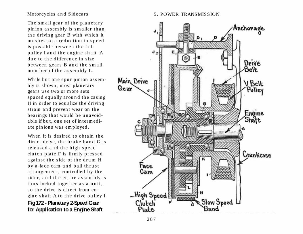
Engine Shaft GearA two-speed and free engine plane-tary gear of English design, andsold under the trade name of “Fitsall,” is shown at Fig. 172. While thearrangement is such that the driveis by means of V-belt, it is possibleto replace the belt pulley with asprocket., and obtain chain drive.The action of this gear is simple,and, if thoroughly understood, itwill serve to make clear the princi-ples underlying speed reduction byall forms of planetary gear sets.

286
Motorcycles and Sidecars 5. POWER TRANSMISSION
Fig 171 - Variable Pulley & FreeEngine Clutch on Rudge-Multi MC
A main driving member thatcarries the assembly is securelykeyed to the engine shaft A andis held firmly in place by athreaded shaft extension thatforms an auxiliary support forthe gear assembly.
When the parts are in the posi-tion shown in the sketch, theengine may turn without drivingthe rear wheel because the maindriving gear will rotate the plan-etary reduction gears L aroundon the bearing stud on whichthey rotate without producingany movement of the pulley I.
If the friction band G is clampedaround the drum H to keep itfrom turning, while the plane-tary pinion assembly L will turnon the stud, the pinion carrier Hcannot rotate and the planetarypinions therefore serve as anintermediate gearing connectingthe main drive gear with thepulley drive gear B. The maindrive gear is about the samesize as the larger gear of theplanetary pinion assembly andtherefore turns it at about thesame speed.
287
Motorcycles and Sidecars 5. POWER TRANSMISSION
Fig 172 - Planetary 2-Speed Gearfor Application to a Engine Shaft
The small gear of the planetarypinion assembly is smaller thanthe driving gear B with which itmeshes so a reduction in speedis possible between the Leltpulley I and the engine shaft .Adue to the difference in sizebetween gears B and the smallmember of the assembly L.
While but one spur pinion assem-bly is shown, most planetarygears use two or more setsspaced equally around the casingH in order to equalize the drivingstrain and prevent wear on thebearings that would be unavoid-able if but, one set of intermedi-ate pinions was employed.
When it is desired to obtain thedirect drive, the brake band G isreleased and the high speedclutch plate F is firmly pressedagainst the side of the drum Hby a face cam and ball thrustarrangement, controlled by therider, and the entire assembly isthus locked together as a unit,so the drive is direct from en-gine shaft A to the drive pulley I.

288
Motorcycles and Sidecars 5. POWER TRANSMISSION
Countershaft GearsCountershaft gears are made ininfinite variety, and they mayform part of the power plantunit or be attached to thecrank-hanger. The views of theDe-Luxe motor at Figs. 173 and174 show clearly the externalappearance of a two-speed gearof the countershaft type when itforms part of the power plant.This makes it possible to utilizethe regular pedal-starting gear,if desirable, as the change-speed gearing is placed forwardof the crank-hanger and is inde-pendent of it.
Where the change-speed gearingis not a part of the engine caseand must he supported from thecrank-hanger, it is sometimesimpossible to utilize the pedalgear for starting the engine, soan auxiliary starting-crank ar-rangement, such as shown atFig. 175, must be used to turnthe engine crankshaft over andstart the motor.
The arrangement may be easilyunderstood from the illustration.

289
Motorcycles and Sidecars 5. POWER TRANSMISSION
The view at A shows the startingcrank in place with the jawclutch making a suitable con-nection between the starting-handle shaft and the main gearshaft, as soon as the enginestarts the handle is auto mati-cally released, and a coil springwill force the starting clutch outof engagement so that the mem-ber to which the starting crankis attached does not rotate ex-cept when it is pressed intoengagement with the clutchmember by suitable end pres-sure on the starting handle.
The arrangement of the clutchand change speed gearing inthe Michaelson unit power plantis outlined at Fig. 176.
In this, the multiple disc clutchof the usual pattern is attachedto an extension of the enginecrankshaft, and drives an in-termediate gear assembly con-sisting of two gears, one largerthan the other, which in turntransmit the crankshaft motionto a suitable spur gear on themain driving shaft of the two-speed gearing.

290
Motorcycles and Sidecars 5. POWER TRANSMISSION
The arrangement of the gears inthis variable speed member ispractically the same as thoseshown at Fig. 179. A shiftingclutch member clutches eitherof the gears to the sprocket-drive shaft.
The use of the intermediate gearmember provides for a first-speed reduction gear completelyenclosed and running in oil.This power-transmitting elementtakes the place of the usualshort chain that joins the enginecrankshaft to the conventionalcountershaft gear arrangementsuch as outlined at Fig. 178.
The engine is started by a smallsprocket member that drives asuitably formed clutching mem-ber at one side of the gear caseand which engages the mainshaft of the change-speed gear-ing. This position is preferableto a direct application to theengine crankshaft because theengine is started through theintermediate gears, which in-sures that the crankshaft B canbe maintained at a higher ratethan would be possible by direct
application of the starting han-dle, owing to the geared-updrive between the startingmeans and the crankshaft. Inorder to start the average motor-cycle power plant promptly, it isnecessary to rotate it at a fairlyhigh rate of speed.
This was always an importantadvantage in connection withthe usual pedal-starting gear,because the rear wheel could beturned over fast enough by thefeet to revolve the engine crank-shaft at a higher rate of speedthan is possible with most kick

291
Motorcycles and Sidecars 5. POWER TRANSMISSION
starters or equivalent devices.There are conditions where it isimportant to turn the engineover fast to secure prompt start-ing, such as in cold weatherwhen the gasoline does notvaporize readily. The applicationof the geared-up starting crankgives practically the same rota-tive speed as would be obtainedthrough the conventional pedal-gear arrangement.
The Minneapolis power plantwhich is shown at Fig. 177 issimilar in general arrangementto the Michaelson, but employsa distinctive means of speedchanging. The transmission is ofthe planetary type using positiveclutches for both high and lowspeed which, of course, is madepossible by utilizing a masterclutch on the engine crankshaft.
A jaw clutch member is adaptedto slide on a bushing surround-ing the main shaft, and this maybe engaged either with the num-ber carrying the planetary re-
Fig. 176 - Change Speed Gear inMichaelson Unit Power Plant

292
Motorcycles and Sidecars 5. POWER TRANSMISSION
Fig 177 - Views of a MinneapolisUnit Power Plant and Gear Set
duction or it. can be moved overto push a clutch member inengagement with the drivinggear of the transmission shaft.
When in the position indicated,the gear that drives the trans-mission shaft is clutched to thatmember if the jaw clutch isrlliIvell to the other extreme, aseries of projections extendingfrom the face of the clutchshifter engage suitable depres-sions in the planetary gear-carrying plate, and keep thatmember from rotating becausethe jaw clutch shifter is securelyanchored to a through bolt,extending from one side of thegear case to the other, whichkeeps it from rotation.
When used in connection withplanetary gearing, it takes theplace of the usual band clutch,and the drive is then to themember carrying the drivenspur gear inside of the case, andthreaded on the outside to re-ceive the driving sprocket.

293
Motorcycles and Sidecars 5. POWER TRANSMISSION
With this construction, it is im-perative that the master clutch bereleased before either the high orlow speed is engaged.
The usual installation of a coun-tershaft gear of the shifting jawclutch type is shown at Fig. 178.At the bottom or plan view, therelation of the gear to the enginebase, and the method of drivingfrom the engine crankshaft, isclearly shown. A compensatingclutch at the engine crankslaft isutilized to prevent depreciation ofthe chain through unsteady pow-er application and from thesprocket mounted on that mem-ber, the drive is by chain to thesprocket attached to the mainclutch member that forms part ofthe countershaft gear.
The drive to the rear wheel isfrom the smaller sprocket on thecounter-shaft to a suitablemember on the rear hub. Themethod of shifting the speed isalso depicted, the jaw clutchcontrolling the two speeds is
Fig 178 - Installing Jardine (English)Countershaft Type 2-Speed Gear

294
Motorcycles and Sidecars 5. POWER TRANSMISSION
operated from a small lever at-tached to the top frame tubewhich works on a notched quad-rant providing three stops for thelever. The center one is in neutralposition, and at such times as thesmall lever stands vertically, theshifting clutch in the transmis-sion interior is at a point betweenthe two engaged positions.
Moving the lever to one extreme orthe other will engage the high orlow speed respectively. The clutchis shifted by a foot pedal attachedto the bottom of the bracket sup-porting the power plant.
The interior arrangement of theIndian two-speed gear, which isrepresentative and the original ofall the shifting clutch forms, isshown at Fig. 179. A frictionclutch of the regulation Indianpattern serves as a master clutch,and the drive from the engine isdirectly to a large driven sprocketattached to the clutch casing.
A driven shaft passes throughthe center of a hollow quill orbushing, at one end of whichthe drive sprocket that trans-mits the power to the rear

295
Motorcycles and Sidecars 5. POWER TRANSMISSION
wheels is secured, while at theinside a spur gear is mounted.
The jaw clutch is keyed to thisshaft which is supported at itsother end by a ball bearing. Thisshaft is also hollow, and theclutch release rod passesthrough the center of it. The jawclutch member is adapted to beshifted from its central positionto either the right or left to en-gage suitable teeth projectingfrom the face of the two gears.
The gear that is attached to thebushing carrying the sprocketmeshes with a smaller membercarried on a countershaft to oneside of the main shaft.
A larger gear on the counter-shaft meshes with a smallermember that is normally free torevolve on the main shaft, andwhich is independent of it at alltimes except when the jawclutch is moved over to engagewith the teeth on its face.
With the jaw clutch in the posi-tion shown, even If the masterclutch is engaged, the rearwheel will not turn because the
sleeve carrying the drive sprock-et does not rotate. To obtain thelow speed ratio, the jaw clutchis moved to the right, to makefast to the shaft the smaller ofthe gears mounted on that
member. The drive is then fromthe clutch to the small gear,which, in turn, drives the largegear on the countershaft at alower rate of speed.

296
Motorcycles and Sidecars 5. POWER TRANSMISSION
The other gear member on thecountershaft is smaller than thesprocket drive gear, and a fur-ther reduction of speed is possi-ble between these two.
The driving sprocket is turningin the same direction as themain shaft, but at a lower rateof speed on account of the re-duction gears inter-posed be-tween the sprocket and theclutch-driven shaft.
To obtain the high-speed ratio,the jaw clutch is moved to theleft, and makes the sprocket-drive gear fast to the main shaft.This means that the drivingsprocket would turn at the samespeed as the main shaft towhich the clutch is attached.
The master clutch is shifted bya releasing worm that exertspressure against a rod passingthrough the center of the mainshaft, and attached to the outer-most clutch plate. When thisplate is moved to the left, theclutch springs are compressed,and the driving pressure be-tween the plates is interrupted.
It is necessary to release themaster clutch at all times that thejaw clutch member is shifted,because if the positive clutch ismoved with the friction clutchengaged it will start the motorcy-cle so suddenly that the parts ofthe transmission system niay bestressed to the breaking point.
Another form of countershaftvariable speed gear is shown atFig. 180. This differs from the
type previously described, inthat it is a sliding gear form andprovides three forward speedsinstead of two as is commonpractice. The power from theengine is delivered to the clutchcase by the sprocket A, and theinner member of the clutch isattached to and drives the mainshaft B of the transmission.
A sliding gear D is mounted onthe main shaft, and is provided

297
Motorcycles and Sidecars 5. POWER TRANSMISSION
with clutch projections E onboth sides. When the member Dis moved to the extreme right ofthe gear case, the projectingteeth E clutch correspondingmembers on the small spur gearG, thus locking the gear G tothe main shaft.
The gear G is considerablysmaller than the gear L mount-ed on the counteshaft H, andturns that member at a lowerrate of speed. The drivingsprocket M is attached to abushing to which the sprocket-driving gear is securely fas-tened. The constant mesh gearon the countershaft H thatmeshes with the gear F is small-er than that member, and thusa further reduction in speed isobtained.
The driving sprocket M turns ata considerably lower speed thanthe main driving shaft B, owingto the two reductions obtained,one between the gears G and L,and the other between the smallconstant mesh gear on thecountershaft and the sprocketgear F.
298
Motorcycles and Sidecars 5. POWER TRANSMISSION
If the sliding member B is engagedwith the member K on the counter-shaft there is but one reduction inspeed, and that is between theconstant mesh gears. because thegears D and K are practically thesame size. This is an intermediateratio that is not as slow as the lowspeed, and yet is slower than thedirect drive. If the sliding memberD is moved to the extreme left, theclutch teeth E-1 will engage suit-able members projecting from thegear F, and will lock the sprocketchive gear directly to the main shaftand obtain a direct drive. With thisform of transmission, it is evenmore important to release the mas-ter clutch before speed changes areeffected than it is with the slidingclutch forms in which the gearteeth are always in mesh.
If the sliding member D is movedinto mesh with the gear K, with theclutch engaged, it will be apt toproduce serious damage to theteeth of the two gears, because it isalmost impossible to mesh spurgears when both are in motion. Akick starting gear is incorporatedwith this gear-set.
The pedal crank P which is adaptedto be pushed by the foot of the rideris clutched to the gear N whichmeshes with a much smaller gear 0attached to the main shaft B.
Even if the pedal P is only movedthrough a small portion of a revolu-tion, the engine shaft will be turnedseveral times on account of thegearing of the starter as well as thestep-up between the large sprocketA on the clutch and the smallermember on the engine shaft.
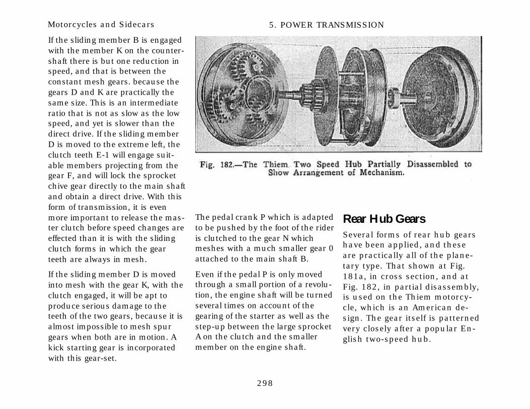
Rear Hub GearsSeveral forms of rear hub gearshave been applied, and theseare practically all of the plane-tary type. That shown at Fig.181a, in cross section, and atFig. 182, in partial disassembly,is used on the Thiem motorcy-cle, which is an American de-sign. The gear itself is patternedvery closely after a popular En-glish two-speed hub.

299
Motorcycles and Sidecars 5. POWER TRANSMISSION
The method of obtaining the lowspeed by the use of planetaryreduction gears is practically thesame as that employed in theengine shaft gear shown at Fig.
172. A suitably brake bandclutches a drum securely fas-tened to the axle, and one of themain gears of the planetaryreduction is also keyed to the
axle. The other sun gear, as thecentral main member is called,is attached to the hub memberproper. The drive from the mo-tor is by V-belt to a pulley rim

300
Motorcycles and Sidecars 5. POWER TRANSMISSION
laced to the drum carrying theplanetary reduction gears by theconventional wire spokes.
When it is desired to apply thelow speed, the brake band thatworks on the outer drum isconstricted and holds that drumand the axle to which it is fas-tened stationary. The planetarypinions are free to revolve ontheir retaining studs and drivethe hub shell because they mustturn it in the same direction,though at a slower rate of speed,than the pulley rim travels onaccount of being forced to rollaround the spur gear keyed tothe axle.
To obtain a high speed, anexpanding band clutch is en-gaged by leverage actuated bya shifting cone, and the entirehub assembly is locked to, andmust turn with the axle. Theprinciple of this gear may bemore easily grasped if one re-members that the axle travelsforward with the road wheelwhen in high speed or directdrive position; that it is heldstationary when in low speed
and that it will revolve back-ward when in the neutral orfree engine position.
The inner brake band serves asa running brake, and will re-tard the hub positively whetherthe gearing is in use or not.
A distinctive form of reductiongear mounted in the rear hub isthat, used in connection withthe Harley-Davidson motorcycle.The gearing is of the bevel formand operates on the planetaryprinciple. A shifting dog clutchis employed in addition to themaster clutch which is of thefriction type.
When moved in one position,the master clutch drives thehub directly, and when it ispushed to the other position itdrives the hub through the me-dium of the bevel-speed reduc-tion gear. The complete device isnot shown in the illustration(Fig. 181), as a clutch assemblyand a friction brake must beadded to the simple hub shownto complete the mechanism.
Forms of hub gears working onthe planetary principle havebeen evolved abroad which pro-vide three forward speeds, butthese are, so complicated thatthey have received practically noapplication in America.
There seems to be no good rea-son for. the use of three-speedgears unless the motorcyclepower plant lacks capacity, and,as the best, American practiceseems to be to provide a two-speed gear more for emergencyuse and to use power plantsthat will have sufficient power toovercome practically all normalresistance on the direct drive orhigh gear, the low gear is to beused only for starting, in hillclimbing or in negotiating unfa-vorable highway surfaces. Prac-tically all of the time the motor-cycle is in use it may be operat-ed on the direct drive or highspeed. Fitting an intermediateratio between the high and thelow is not necessary when thepower plant is of suitable pro-portions, though it might he ofsome value if the machine was

301
Motorcycles and Sidecars 5. POWER TRANSMISSION
under-powered, and the directdrive could only be used underexceptionally favorable operat-ing conditions.
The Sturmey-Archer is a typicalexample of a three-speed hub,and it is said that the lowest gearratio is to be used only whenextremely high resistance mustbe overcome. The internal con-struction can be clearly under-stood by referring to Fig. 182a.
When on the high gear, all partsof the hub are locked togethersolidly as the hub shell is drivendirectly from the driving mem-ber. On the second or interme-diate gear, the drive is obtainedfrom an internal gear memberwhich rolls planetary pinionsaround a stationary central gearintegral with the axle. The re-duced motion of the planetarypinions is transmitted to thewheel hub by a driving memberthat clutches extensions fromthe friction clutch carrier.
When the lowest gear of all isbrought into action, the drive isthrough still another set of pinionsand a further reduction in speed is
effected. The direct drive is obtainedby a plate clutch in the hub interi-or. It is said that a reduction of 47per cent. in speed is obtained onthe intermediate speed, and that afurther reduction of 40 per cent. issecured on the low speed.
The various speed changes areeffected by moving a laterally shift-able member to the right or left,and the lowest speed ratio is ob-tained as the member is moved tothe right. When on the high gear,the cup-shape driven memberengages projections which are onthe rim of the circular or internalgear member driven by the beltpulley. This means that the highgear is direct from the drive pulleycarrier to the plate clutch.
When the intermediate .speed isdesired, the sliding member engag-es with the internal gear carryingthe first set of planetary pinions,and this internal gear meshes withand drives the second train of plan-etary pinions. On the lowest speed,the driven member engages withthe carrier of the second set ofplanetary pinions.
Three Chain SystemsA form of two-speed gear that hasbeen used with some degree ofsuccess on European motorcyclesis that shown at Fig. 183, inwhich a double sprocket is at-tached to the engine crankshaft,and two chains extend to thesprockets on the counter-shaft.
Each of these sprockets mayrevolve independently of theother or both may revolve free ofthe smaller driving sprocketused for driving the rear wheels.It is said that an advantage ofthis type of gear is that bothspeeds are direct and the fric-tion and power loss due to theuse of gear pinions is notpresent.
It is also advanced that thissystem is extremely quiet inaction, and that the clutches,which are of the internal ex-panding type may be used togive a free engine on either gearratio.
The original form is undoubtedlythe Phelon & Moore, which isshown at Fig. 183. The low-gear

302
Motorcycles and Sidecars 5. POWER TRANSMISSION
sprocket, which is the largest, isthe outside member, while thehigh-gear sprocket, which is thesmaller of the two large ones, isthe inside member.
The clutch members act asbearings on which the sprocketsrevolve when the gear is in neu-tral position, but when expand-ed the shoes grip the interior ofthe drum carrying the sprocketsvery tightly and transmit thepower to the small sprocket towhich the brake shoes are fas-tened.
The internal clutches arebrought into engagement bysliding a wedged-shaped mem-ber to the right or left as thecase may be, and spreading outthe brake shoes. In the formshown at Fig. 183, if the wedgebar is moved to the right, thebrake shoe that clutches thehigh speed sprocket will beexpanded, and the drive will befrom the engine shaft to thecountershaft through that mem-ber, while the low gear or largersprocket will revolve freely onthe brake shoes that are not
expanded and which thereforeact w a bearing for that mem-ber. If the wedge bar is moved tothe left, the outside sprocket,will be clutched to the drivingmember, and the smaller orhigh-gear sprocket will revolvefreely on its brake shoes.
It would seem that there wouldbe considerable wear due to timmovement of the sprocket carri-er over the brake shoes, hut thesuccessful use of this form ofchange-speed gear for a nuljlierof years indicates the large sur-face of the bearing and the pro-

303
Motorcycles and Sidecars 5. POWER TRANSMISSION
visions made for lubricatingthem are adequate to preventuntimely depreciation.
The two-speed gear used oil theEnfield (English) motorcycle is ofthe same pattern and is clearlyoutlined at Fig. 184. Either gearratio may be brought. in actionby expanding the hardened steelbands A into one of the drumsB, also of hardened steel, towhich the chain wheels C aresecured.
The change in gear ratio is ob-tained in the same manner as inthe Phelon & Moore by drivingthrough the large sprocket forlow speed and through thesmaller sprocket for high speed.The expanding bands A arecarried on internal drums Dwhich take the drive, and whichare keyed on the ball hearingshaft E that is employed to drivethe sprocket F that, connectswith the rear hub.
The clutches are engaged bycams cut into the block G,which is capable of gliding ineither direction according to

304
Motorcycles and Sidecars 5. POWER TRANSMISSION
which gear is desired. The ac-tion of the cam is to force one ofthe pegs H against the splitroller I, which forces open theband A until it engages with B,which is rotated by the engine.The object of splitting the roller Iis to permit the clutch to pickup smoothly.
The block G which contains thecam is moved by the rack J andthe pinion K, which is operatedby a vertical shaft and lever atthe top of the crank. Three pairsof ca.nL numbered 1, 2, and 3are cut in G, each of these being.005 inch higher than the onepreceding it. Should the band Awear to such a point that cam Ais not sufficiently high to oper-ate it., the member C may beturned around so the next larg-er cam will be used to expandthe brake band. The practicalapplication of this gear to aClement (french) motorcycle isclearly outlined at Fig.185
. .

305
Motorcycles and Sidecars 5. POWER TRANSMISSION
Planetary Countershaft GearSeveral of the American motor-cycles employ a planetary re-duction gear mounted on anextension projecting from thecrank-hanger. A successfulform, which is used on the Ex-celsior motorcycle is shown atFig. 186.
The drive from the motor is tothe sprocket B attached to theplanetary gear carrier A whichalso forms the male member ofthe friction clutch employed fordirect drive.
When it is desired to obtain alow speed ratio, the femalemember of the high speedclutch is pulled out of engage-ment with the male member,which is fixed and the V-shapebronze brake band M is tight-ened around the carrier I, towhich is attached the gear H.
As this gear is held stationary,the planetary pinions mustrotate on their studs as they arecarried around by the memberA, and, as they turn at the sametime, they drive the gear E,
which is securely keyed to thebushing to which the sprocket Gis fastened.
To obtain a high gear ratio, themember M is released and thefemale member J, of the coneclutch, is brought into engage-ment with the male member sothe drive is direct, from the
sprocket B through the clutchmembers to the member F towhich the wheel driving sprock-et G is keyed.
The member J is actuated bythe operating worm K which isoscillated by the lever L. Theentire construction is mountedon ball bearings so but little
Fig 186 - The 2-Speed Planetary Gearset of the CountershaftType used on the Excelsior Motorcycles

306
Motorcycles and Sidecars 5. POWER TRANSMISSION
friction is present, and the lia-bility of bearing depreciation isproportionately reduced. Thepractical installation of thisgear, and the method of opera-tion by a single handle, is clear-ly shown at Fig. 166.
If the handle is moved in onedirection the low speed is ap-plied, and in the other positionthe high speed will be engaged.When in the position shown orapproximately at the center ofthe notched quadrant, the gearis in the free engine position asneither the high-speed clutch Jnor the low-speed friction bandM is in engagement with theirrespective co-acting members.
Sliding Gear TypeThe sliding gear forms whichhave been so generally used inautomobile practice have re-ceived but limited application inmotorcycles. This is not as pop-ular among motorcycle design-ers as the individual clutchsystems are, because consider-able damage may result to thetransmission gear when handled
by the inexperienced rider.
If attempt is made to change thespeeds without releasing themain clutch member, the gearteeth will be burred or destroyedentirely. These pieces may getinto the transmission and wreckthe entire construction. It iscontended by those who favor
this construction that there isno more reason for the motorcy-cle rider to damage a transmis-sion than there is for the auto-mobile operator.
As a general rule, the motorcycle isnot intended to be handled byexpert mechanics, and the simplerthe control system the more popu-lar the motorcycle will be.

307
Motorcycles and Sidecars 5. POWER TRANSMISSION
In the individual clutch form,notably in the two-clutch plane-tary types, one cannot, obtain aspeed ratio without first de-clutching the engine. In thesliding gear, forms that are pat-terned after automobile practice,it is possible to shift gearswhether the clutch is released orengaged.
A simple and effective slidinggear system which has beensuccessfully used on Piercemotorcycle is shown at, Fig. 187with a portion of the gear casecut away to show the arrange-ment of the sliding members,and in section at Fig. 188 sothat the method of actuating thesliding members and the frictionclutch simultaneously may bereadily ascertained.
This sliding gear transmissiondoes not have the main disad-vantage to that form of gearing,because when the shifting mem-ber is moved from one gear ratioto the other, the clutch is re-leased automatically by thedouble cone arrangement, andwill not be fully engaged until
the shifting member is com-pletely in mesh with one or theother of the gears attached tothe propeller shaft.

308
Motorcycles and Sidecars 5. POWER TRANSMISSION
Power Transmission MethodsA point on which considerabledifference of opinion has alwaysexisted has been the best meth-od of conveying the engine pow-
er to the traction member of themotorcycle. At the present time,belt, chain and gear drive are allused, and various combinationsof these three forms are some-times used in conjunction. Some
systems of power transmissionare more efficient than others,and, as a rule, those that. arethe most positive and that willtransmit the engine power withminimum loss due to slipping

309
Motorcycles and Sidecars 5. POWER TRANSMISSION
are also apt to have other disad-vantages which would tend tofavor the forms where the drivewas by more flexible means.
The two conventional methodsof driving a motorcycle are out-lined at Fig. 189. The first sys-tem to be applied, and the onethat was formerly the most pop-ular, is by leather belt, whichnay be any one of a variety offorms.
The type illustrated is a flat beltof the form that has been sowidely used in driving the ma-chine tools of the mechanic, andpractically all other forms ofmachinery for many years. Theother, which is more positive,involves the use of chains andsprockets.
The latter method of driving wasused on the first automobiles,just as soon as it was definitelydetermined that the flat beltdrive systems were not practicalfor the heavier forms of four-wheeled vehicles. These systemswill be considered more in detailin proper sequence. Drive bygearing is general at the present
time in automobile practice, andis followed to some extent bymotorcycle designers. Either thebevel or worm gear drive may beused in connection with a shaftextending from the power plant.
The single-belt drive, either bymeans of flat or V-belt is the
simplest power transmissionsystem, because it is possible toobtain a degree of free engineaction without the use of aclutch if a jockey pulley or idleris employed to tighten the belt.
With a V-belt, it is necessary touse a free engine clutch of someform to obtain the free engine

310
Motorcycles and Sidecars 5. POWER TRANSMISSION
which is also true of the variouspositive driving- means such aschains and gears. The system oftransmission to use depends toa large extent on the individualpreferences of the rider anddesigner, because each systemhas its advantages, and all havebeen proven practical. When itcomes to a question of efficien-cy, the drive by single chain orV-belt is undoubtedly the onethat will transmit poster withthe least loss.
With a properly adjusted V-belt,there is practically no slipping,and a flexible drive is obtained.A certain amount of power isrequired to bend the belt overthe pulleys, but this is probablyno more than would be con-sumed by friction of the variousmembers of the chain and thefriction between the chains andsprockets.
The figures in the following ta-ble, over, have been generallyaccepted by automobile design-ers, and apply just as well tosimilar driving systems used inmotorcycle practice.
Carefully made brake tests havedemonstrated that the powerloss with a single-chain or V-belt drive is not greater than 10per cent., whereas with a dou-ble-chain arrangement, which isthe one generally used, about20 per cent. of the power is lostin transmission. The type ofchange-speed gearing used alsohas some bearing upon theefficiency of the driving system.
Gears of the planetary type willlose more power when on thelow speed ratio than will eitherthe sliding gear or sliding clutchforms, but on the other handthere is practically no loss whenon the high speed because theassembly turns as a unit andthe only power consumed is atthe bearings. In either the slid-ing clutch or sliding gear forms,the countershaft is always inaction due to the constant meshgears, and some power is con-sumed at that point in additionto the main bearing.
While the positive driving sys-tems are the most practical,some unconventional systems of
propulsion have been devisedand tried out in an experimentalway. These are usually in theform of attachments intendedfor application to the ordinaryfoot-propelled bicycle to convertit into a power-propelled type.One of these, which was exhibit-ed at the recent motorcycleshows, is shown at Fig. 190,and propulsion is obtained byan air propeller of the same typeused in aeronautical practice. Itis said that with the latest formsof air propellers, more powercan be obtained with a givenengine size than will be deliv-ered by marine propellers work-ing in water. It is also claimedthat the efficiency of a marinepropeller will rarely rise higherthan 60 per cent., whileaeroplane propellers working inair may be 90 per cent. effective.
The air propeller of the deviceshown at Fig. 190 has but littlemore spread than the span ofthe average bicycle handle-bars,and when used in connectionwith the small motor shown, thethrust is sufficient to push an

311
Motorcycles and Sidecars 5. POWER TRANSMISSION
TRANSMISSION EFFICIENCY OF DIFFERENT TYPES OF MECHANISM(WORDY BEAUMONT)
Source, of Loss of Power. Amount of Loss, Per Cent. Efficiency Per Cent.100.0
When driving direct:
One chain 3.0One and one-half pairs of hearing, 7.5 89.5
With epicyclic speed gear in operation, add 15.0 74.5
When driving direct:
One set of gear 5.0Two pairs of bearings 10.0
Partially active hearings 3.0 82.0With change-speed reduction gear in operation, add 12.0 70.0
ordinary bicycle 30 miles perhour over good roads. The en-gine is a three-port, two-cycletype, and with a bore of 2-1/2inches and a stroke of 2-1/4inches, at a speed of 2,500 revo-lutions per minute, developspower ample for the purpose.The engine weighs but 16pounds, and the entire attach-ment, including propeller, igni-
tion system and fuel tank is saidto weigh less than 40 pounds.While this system of propulsionis practical in air and marinecraft and may have some degreeof merit, it does not appear to beanything more than freak con-struction, and is only illustratedto show all unconventionalmethod of bicycle propulsion.Such devices cannot give the
satisfactory service obtainedfrom properly designed motorcy-cles as the average bicycleframe, tires, etc., are not builtwith the idea of attaching me-chanical power.

312
Motorcycles and Sidecars 5. POWER TRANSMISSION
The Wall Auto Wheel, which device is of En-glish design, illustrated at Fig. 191, has consid-erably more merit than the air propeller, andhas received practical application abroad.
It consists of a separate wheel to which a min-iature power plant is attached, and it, is in-tended to be secured to the rear frame of abicycle parallel with the rear wheel. The en-gine is air-cooled and has a bore and stroke of2-1/4 and 2-1/2 inches respectively. It isclaimed that it will develop one horse-power,which is said to be ample to propel a bicycle atsafe speed.
The engine is of the four-cycle type, has anexternal flywheel, and includes a simple formof two-speed gear in an extension of the motorcrankcase. The drive from the two-speed gearto a sprocket mounted on the wheel hub is bymeans of a short roller chain.
The wheel is 22 inches in diameter and is car-ried in a substantial tubular frame-work towhich the motor and fuel tank are secured.
This device has been produced for more thanfive years by the manufacturers, which have afactory in London, and, while it is not claimedthat it will give the same results as a regularlydesigned motorcycle, still it permits of convert-ing a pedal cycle into a self-propelled form, andon level roads and in practically all city work, itwill undoubtedly be able to furnish power

313
Motorcycles and Sidecars 5. POWER TRANSMISSION
enough to drive the bicycle with-out. any muscular exertion onthe part of the rider.
It is said that the two-speedgear makes it possible to climball reasonable grades. An at-tachment, of this kind can beused only on good roads andunder favorable conditions, butthe device is novel, thoroughlypractical and probably will ap-peal to people of conservativetemperament who will be satis-fied with medium speed, andwho do not intend to use thedevice in touring.
The American rights have beenacquired by a prominent manu-facturer and if it successfullystands the test that it is nowundergoing it will be marketedin this country.
Belt Drive SystemsBefore describing the varioussystems of power transmissionby belt, it may be well to reviewthe advantages advanced bythose who favor that form oftransmission.
One of the most important claimsrelates to the flexibility of beltdrive and its power of absorbingthe road shocks and machinevibration, which, it is contended,results in minimum depreciationof the power plant. It is alsoclaimed that the reverse is true ofthe positive driving system whichtransmits the road shocks to theentire machine.
The belt running over pulleys issilent because if a flat belt isused it is endless, and there areno metallic parts to strike andclick. A V-belt may have a me-tallic coupling but this does notcome in contact with the pul-leys, and is therefore equallysilent. Another feature of beltdrive is said to be the absence ofcomplicated parts.

314
Motorcycles and Sidecars 5. POWER TRANSMISSION
The conventional form of belttransmission consists of twogrooved or flanged wheels, aconnecting belt and a coupling,if a V-belt; or an idler or jockeypulley, if a flat belt. When a beltstretches, the rear wheel may beadjusted to compensate for theincrease in length.
It is said that the rider of a belt-driven machine experiences nodiscomfort from any irregulari-ties of motor operation, as theflexible belt will take care ofsudden changes of speed.Should a motor stop suddenly,as by breaking or sticking ofsome of the important internalparts, a belt will slip sufficientlyto enable the rider to retain hisplace on the machine. A rigidform of drive would be apt toresult in a sudden stop, andthrow the rider.
The factor of cleanliness is alsogiven some consideration by thebelt enthusiast, and it is evidentthat belts are naturally morecleanly because they do notneed the lubrication that is nec-essary with chain drive.
With the various positive drivingsystems, it is imperative thatthe parts be maintained in ab-solute alinement or there will beconsiderable delrreciation of themechanism and loss of power.
With belt drive, any slight misa-linement does not, produceappreciable wear, and there isbut little loss in transmissionefficiency due to this condition.It is the belt that depreciatesand not the pulleys, as these
frequently outlast from three tofive belts before they becomeworn enough to reduce the effi-ciency of the drive.
If one considers the chain trans-mission, defective alinementmean that the chain or sprock-ets, and in most cases both, willwear unduly, and have a mate-rial reduction of the usefulworking life.

315
Motorcycles and Sidecars 5. POWER TRANSMISSION
When a chain or its sprocketsare worn, efficiency of drive canonly be restored by renewingboth members. It is a knownfact among mechanics that anew chain will not work well onworn sprockets, nor will an oldchain function properly on newsprockets.
The following summary of theadvantages of belt transmissionis given by a prominent. manu-facturer of these elements: Belttransmission causes less troubleand is less expensive than otherforms of drive, because it. is not.seriously affected by a loss ofalinement., which causes othertransmissions to wear apprecia-bly and frequently results incostly replacements.
The flexible transmission insuresminimum wear of the powerplant, because the elastic drivingmedium will transmit fewer roadshocks than the positive form.This means that there is less wearon bearings and gears because ofthe slipping under abnormalloads, such as quick starting,rapid acceleration, etc.
These same features also con-tribute materially to the comfortof the rider because of smoothaction. It is the least complicat-ed, and therefore it is the leastliable to get out of order. Thefeature of silence is also com-
mendable, as drive is by leatherto metal contact instead of met-al to metal connections.
The application of flat belt driveto one of the Harley-Davidsonmodels is shown at Fig. 193.

316
Motorcycles and Sidecars 5. POWER TRANSMISSION
The method of operating thebelt idler or jockey pulley onthis machine is clearly shownat. Fig. 193.
The idler is carried at the end ofa bell crank which has a seg-ment of a gear as its othermember. These gear teeth en-gage with suitable membersformed at the lower portion ofthe operating handle.
As the handle is pulled towardthe rider, the idler pulley moveson an arc of a circle having aradius equal to the center dis-tance between the idler pulleybearings and the pulley center.
The flat belt may be normallyloose when the idler is in theposition shown, but when thepulley is raised to the positionindicated by the dotted line thebelt is made to hug the enginepulley very closely, the effectivearc of contact between the beltand, the driving pulley is in-creased and a more effectivedrive obtained.
The view at the right of Fig. 193shows one method of compen-
sating for the variation in pedalsprocket centers as the rearwheel is moved to allow for beltstretch.
A small ball-bearing idler ismounted in a slotted support,and is moved down in the slot totighten a loose chain, andmoved up to loosen a tightchain.
Many of the belt drive machinesstilt retain the pedaling chain,
and suitable provision must bemade to keep that member inproper adjustment.
The V-belt drive which is usedon the Rudge-Multi is shown atFig. 194. The belt, is a combina-tion rubber and canvas form,and is utilized in conjunctionwith a variable pulley and fric-tion clutch attached to the pow-er plant.

317
Motorcycles and Sidecars 5. POWER TRANSMISSION
Types of Driving BeltsThe various forms of belts thathave been applied for motorcy-cle propulsion are outlined atFig. 195. That at A is a twisted,round rawhide belt that was thefirst form to be used in motorcy-cle service. It had one advan-tage, and that was that its ten-sion could be increased whendesired by twisting the beltmore closely together.
A grave disadvantage was that itwas materially affected by chang-es in weather, and was apt tostretch very much when wet, andshrink very fast when drying. Thisform was soon succeeded by theflat belt depicted at B, which isthe same form that has beenwidely used for power transmis-sion in our workshops.
The V-belts were the next to re-ceive general application. Thesemay he divided into two mainclasses, one of which comprisesall belts made of leather, whilethe other includes those made ofother materials, such as canvasand rubber vulcanized together. Atypical leather V-belt, the Dueo-
Flex is outlined at, C, and a rub-ber belt, the Shamrock-Gloria isdepicted at D.
Various expedients are used bydesigners to secure flexible V-belts, as it is imperative that abelt bend easily in order that itmay follow the contour of the
small driving pulley attached tothe engine crank-shaft. Thespecial construction outlined atC involves the use of two contin-uous layers of leather to whichare attached overlapping piecesthat are to form the third andfourth plies of the belt.

318
Motorcycles and Sidecars 5. POWER TRANSMISSION
In the moulded rubber and canvasforms, shown at D, notches are cutin the bottom of the belt at fre-quent. intervals, which permit thebelt to describe a curve of smallradius when the spaces close in asindicated, due to the bending of thebelt.
The usual construction of a leatherbelt of the V-form is outlined at Fig.196. The belt consists of two con-tinuous plies of leather that areriveted together between leatherblocks with tubular rivets. Theleather block used on the bottom ofthe belt is not as long as that on theupper part, and this constructionpermits of considerable flexibility.
The Wata-Wata, an English belt,is shown at Fig. 197. In thisconstruction, the upper andlower plies of the belt are sepa-rated by spacer blocks of archformation, which allow the beltto bend around a circle of smallradius because the lower por-tion or ply of the belt will fill thespace between the blocks andpermit the hell. to bend easily.The ends of V-belts are fastenedtogether by metal hook mem-
bers which are made in a largevariety of forms, one of which isshown in this illustration.
Another English belt which is adistinctive construction, andwhich is said to give very satis-factory service, is shown at Fig.
198. This is known as the Whit-tle belt, and is a compositestructure made of steel linkscarrying suitable bearing pinsspaced between leather links.
The two leather links are fastenedtogether by a short regular patternwood screw as indicated.

319
Motorcycles and Sidecars 5. POWER TRANSMISSION
Some of the forms of belt fasten-ers that have received a readymarket are shown at Fig. 199.That at A is a simple form con-sisting of a pair of hinges havingdownwardly extending prongs togrip the belt, joined together bya simple hook member.
The form at B uses a quick de-tachable hook which permits ofsome adjustment by usinghooks of different, lengths. Theform at C consists of a link ofroller chain joining two simpleduplicate V-shaped memberscarrying the screws for attach-ment to the belt.
The wire hook depicted at D isthe form of connector used withtwisted rawhide belt. Anothertype of connector which providessome opportunity for adjustmentis shown at E.
When the belt stretches, theconnecting member may beused to shorten the belt. bychanging its position. Instead ofbearing at the extreme end oneof the connecting members maybe brought nearer the other byplacing it in the bearing at the
upper portion of the connectorring.
Various tools are necessary tomaintain belt efficiency. One ofthese, which is shown at A, Fig.200, is employed to cut beltingof the V-form smoothly andaccurately. It consists of a suit-
able casting member carrying asliding cutting knife guided byslots in the casing, which isforced down to sever the belt bya set screw bearing against thehack of the cutting blade. Theother set screw is utilized toclamp the belt tightly against

320
Motorcycles and Sidecars 5. POWER TRANSMISSION
the movablelower plate whichmay be raisedwhen desired toaccommodatesmaller sizes ofbelts.
Practically all ofthe connectorsused with V-beltsrequire that.holes be made inthe belts to per-mit of passingthe screw thatclamps the con-nector to the beltthrough it.

321
Motorcycles and Sidecars 5. POWER TRANSMISSION
A punch for making theseholes is shown at Fig. 200, B.This is a double member,and the thumb-screw towhich the punch is attachedmay be placed at either end.When in the position shownit will punch one-inch belt,and if the screw is reversed,the device can be used forpiercing seven-eighths-inchV-belt.
After a belt has been short-ened a number of times, apoint will be reached wherethe ends will be too far apartto receive a standard connec-tor of the simple form. Insuch cases, the links shownat C may be used to advan-tage because the center ofthe connector is composed ofa block of rubber beveled offat the same angle as the V-belt. This grips the pulleyand prevents slipping ornoisy action which would beapt to result if a. connector ofthe simpler form was used.

322
Motorcycles and Sidecars 5. POWER TRANSMISSION
Standard BeltsThe regular pattern V-belt ismade to run on pulleys that.have the driving faces beveledso that the included angle be-tween the flanges is 28 degrees.If trouble is experienced withslipping of a V-belt and thesubstitution of a new memberfor the old one does not cure thetrouble, a gauge may be made ofsheet metal and used as indicat-ed at. Fig. 201.
If the pulley flanges are hol-lowed out, which would be aptto result after the pulleys havebeen in use for some time, thiscondition will be clearly indicat-ed by the fit between the gaugeand the flanges.
Belts are made in a variety ofwidths, and are usually of spe-cial tannage because the ordi-nary oak-tanned leather usedfor belting in machine shops isabsolutely unsuitable for thework demanded of a motorcycledrive.
Chrome-tanned leather is gener-ally used for belts because this

323
Motorcycles and Sidecars 5. POWER TRANSMISSION
produces a tough, sinewy mate-rial best adapted to resist oil,water and heat generated byexcessive pulley friction.
Chrome-tanned leather also hasgreater tensile strength than theoak-tanned and it will transmitmore power. It is also more flexi-ble, will not slip when wet, and isnot apt to curl on the edges orstretch as much as the beltingmade by the other processes.
Flat belts are usually made intwo plies and will range from 1-1/2 to 2-1/2 inches wide, thevariations in size being by incre-ments of one-eighth inch. Natu-rally, the greater the amount ofpower to be transmitted, thewider the belt must be to takethe augmented pull.
The plies are not only cementedtogether but, in some instances,they are also stitched at theedges. The cement used shouldbe heat, and water-proof, and itis also necessary to stretch thebolts a number of time aftercementing before the belt isready for use, to give them aninitial permanent set.
In making V-belts, two continu-ous plies in the forms intendedfor medium-powered engines,and three continuous plies onthe forms devised for hungerpower plants are cemented to-gether, and then special two-plyblocks are riveted to the contin-uous plies with steel rivets toobtain the required depth offriction surface. The blocks areof special construction, in orderto enable the belt. to conformmore readily to the small enginepulleys. All standard V-belts,whether made of rubber or
leather have a 28 degree includ-ed angle.
Belts vary in length from 7 to 9feet, and the average length isabout 8 feet 6 inches. Leatherbelt is used almost exclusivelyin the United States, though therubber and canvas V-belt ismore popular abroad. The ad-vantage of rubber belting is thatit is not apt to be affected bywater, but it is not as flexible asthe leather belt, nor dues ithave the same amount of adhe-sion to the belt pulleys.

324
Motorcycles and Sidecars 5. POWER TRANSMISSION
Flat belt pulleys areusually made ofcast iron coveredwith a layer ofleather, or a laggingof woven wire-as-bestos fabric, inorder to securegreater adhesionbetween the beltand pulley.
Owing to the largeamount of surfaceon the rear drivingpulley, it is notcustomary to pro-vide any lagging onthat member, assufficient adhesionis obtained withoutit.
Lagging is not neces-sary on V-belt pul-leys, because thetendency of the belt isto wedge itself in thespace between theflanges, and as thepower developed bythe engine increases,the adhesion aug-
ments proportionately because of a greaterwedging effect.
The four-ply V-belt’s vary in width from 3/4 inch to 1-1/4 inches by increments ofone-eighth inch, and the five-ply belt,which is intended for use with powerfultwin motors will vary from 1-1/8 inches to1-1/2 inches in width.
There is no intermediate size between 1-1/4 inches and 1-1/2 inches V-belt.
The width of a V-belt is always measuredat the top.

325
Motorcycles and Sidecars 5. POWER TRANSMISSION
The writer has made a careful analysis of belt drive machines produced by American manufacturersfor several years, in order to arrive at the average practice as it relates to the sizes of belts used withvarious motor horsepowers.
The following tabulation may prove useful for reference:
Single Cylinders, up to 2-1/2 horsepower (Old Style Machines) :Flat Belt 1-1/4 to 1-1/2 inches wide
Twisted Rawhide 5/8 to 3/4 inch dia.V-Belt 3/4 to 7/8 inch wide
Single Cylinders, 2-1/2 to 5 horsepower:Flat Belt,2-ply l-1/2 to 1-5/8 inches wideV-Belt, 4-ply 7/8 to 1 inch wide
Two Cylinder, up to 7 horsepower:Flat Belt, 2-ply 1-5/8 to 1-3/4 inches wideV-Belt, 4-ply 1 to 1-1/4 inches wide
Two Cylinder, up to 9 horsepower:Flat. Belt, 3-ply 1-3/4 to 2-1/4 inches wideV-Belt, 5-ply 1-1/4 to 1-1/2 inches wide

326
Motorcycles and Sidecars 5. POWER TRANSMISSION
Advantages of Drive by ChainsThe credit, of being pioneers inthe application of chain drive onmotorcycles belongs to theHendee Manufacturing Compa-ny in this country, and toMessrs Phelon & Moore in En-gland. It was adopted by both ofthese makers on standard stockproducts in the year 1900, andboth have been unusually loyaland have consistently advocatedchain drive ever since.
Other makers followed their ex-ample, but they either did notrealize that in order to enjoy thereal benefit given by the chainsthat the machine must be espe-cially designed for them or elsethe majority of motorcycle en-gines in those days were not assmooth-running as the creationsof today, because for a time, thechain transmission was not gen-erally favored on account of thealleged harshness of the drive.
Other influences, however, wereat work, and the consequentimprovement and increase ofpower in the engine, and the
use of sidecars, showed that thebelt drive was not always ade-quate for powerful motors pull-ing heavy loads unless made ofexcessively large size.
Various cushioning devices werealso evolved in order to relievethe mechanism of the shock,clue to positive transmission ofpower and a review of currentpractice indicates that chaindrive is standard en most of thebest-known American machines,and is generally accepted asproducing a moderately silent,smooth-acting and reliabletransmission. In Europe, thebelt is still the most popularform of power transmission, butindications point to a graduallyincreasing appreciation of chaindrive in both England andFrance.
There has never been any ques-tion regarding the positivenessand efficiency of chain transmis-sion. In fact, the first objectionsadvanced against it was that iterred in being too positive.
The early forms of motorcycleengines, especially the big singlecylinder power plants did notdeliver a very even turning mo-ment as the power was appliedas a series of violent shocks.
As previously stated, the beltequalized the drive to someextent by slipping and stretch-ing while the chain, as originallyapplied, transmitted the shocksto the machine, and thus notonly caused considerable wearon the tires but promoted thediscomfort of the rider. Theintroduction of better balancedengines and more especially ofvarious compensating clutchesand cushioning devices of onesort, or another promoted thegeneral adoption of chain drive.
An important advantage ofchains is that these do not needto be tight to transmit power,which is absolutely necessary inconnection with the use of belts,especially the flat belt. In orderto reduce belt slip, it is neces-sary that they be tight, and thebelt pull causes considerableunnecessary friction on the
327
Motorcycles and Sidecars 5. POWER TRANSMISSION
engine bearings, especially ofthe plain type. With the chain,no initial tension is necessary,and the frictional loss due tohigh bearing pressures is not aslarge as with a tight belt.
In order to use the chains suc-cessfully, the conditions underwhich they work to the bestadvantage must be fully real-ized. The removal of belt pulleysand the substitution of sprock-ets, and the use of a chain in-stead of a belt, does not meanthat, satisfactory chain drive willbe obtained.
On the contrary, essential con-ditions peculiar to chain drivemust, be properly taken intoaccount.
First, the nature of the loadmust be understood. The actionof the four-cycle internal com-bustion engine consists of aseries of power strokes due tothe explosion of gases which areinterposed between periods ofneutral or even negative effortwhile the explosion forces thepiston violently downward, dur-
ing the other three strokes andespecially on the compressionstroke, the resistance is exactlyreversed.
A load of this nature is generallyknown as “impulsive,” and ismuch more severe on the trans-mission system than the regularturning moment of an electricmotor or the smooth action of afour-cylinder gasoline powerplant. Consequently, if the chaindrive is to be a thorough suc-cess, the shocks due to unevenpower application must be re-duced or absorbed as far aspossible by some cushioningmechanism.
Another thing that must betaken into consideration is thatthe speed of a motorcycle engineis very high, and, consequently,the chain speed is correspond-ingly fast. This is especially trueof the first reduction or counter-shaft drive chain.
It is not generally realized thatchain must travel at a velocity of1,500 to 3,000 feet per minute,and that the impact between the
rollers of the chain and theteeth of the sprockets is verysevere and frequent. It is there-fore important that the chainsbe kept thoroughly lubricated sothe blows on the rollers may besoftened by the interposition ofa film of lubricant both on theoutside of the roller—which isbest attained by the use of anoil-bath gear case—and in thebush and rivet bearings. Thatthe roller should be free to turnis also most important, since thewear is thereby distributed.
In view of this last consider-ation, it is very necessary tomake sure that the sprocketsare in perfect alinement. Other-wise, the teeth cut into the sideplates of the chain, on whichthey wear a shoulder or ridge,which often causes the rollers tostick, with the result that theimpact on the roller alwayscomes in the same place, tend-ing to break it.
Correct adjustment also is ofcourse necessary, as, if thechain is too slack, it tends tomount the wheel teeth and also

328
Motorcycles and Sidecars 5. POWER TRANSMISSION
“whips,” which may have theeffect of breaking the rollers,and in any case, intensifies thewear. The provision of a gearcase, or at least some form ofchainguard, is highly desirable.Mud is not a satisfactory lubri-cant, and it is hopeless to ex-pect the best results from achain which is coated inside andout with slush and grit. Thenatural result is stiff joints,broken rollers, and rapid wear.
A point to be looked to in de-signing a drive is that the num-ber of links in the chain fromengine to countershaft shouldnot be an even multiple of thenumber of teeth in the engine-shaft sprocket as if this is thecase the force of the explosioncomes more often on certainrollers than on the rest. To sumup, the three essentials to belooked for in a motorcycle driveare: First, some species of slip-ping or cushioning device; sec-ond, eflicient and thoroughlubrication, and third, a reason-able chain speed.
On this last point, a compromise
has to he aimed at. The chainspeed may be reduced by reduc-ing the diameter of the sprock-ets, i. e., the number of teeth.But, other things being equal, asmall sprocket is more severe onthe chain than a larger one,owing to the increased angle at,which the wheel meets thechain. Normally speaking, thebest results will he attained withdriver or engine-shaft sprocketshaving from 15 to 17 teeth.
Single Chain DriveThe simplest form of chaintransmission and the most,efficient is the single chain drivewhich, to date, has not beenextensively applied in motorcy-cle practice. The method of us-ing a single chain is clearly out-lined at Fig. 202. This involvesthe use of an engine-shaftclutch, which also acts as acushioning device, from whichthe drive is to a large sprocketmounted on the rear wheel hub.In the machine shown, the rearsprocket has 64 teeth and theengine sprocket from 16 to 18
teeth. The system of transmis-sion is efficient, and about theonly disadvantage that can beadvanced against it is that thechain must be kept tight, be-cause if loose it will be apt toflap or whip, owing to its length.
Another method of using a sin-gle chain is in combination withan undergeared drive and isoutlined at Fig. 203. In this, thefirst reduction is by a spur pin-ion attached to the enginecrankshaft which meshes withan internal gear that turns thedriving sprocket.
As practically all of the reduction inspeed may be obtained between thegears, the front sprocket may bemade nearly as large as the rearone, and the chain is operatingunder very favorable conditions, asrelates to both chain speed andbending.
The single-chain direct drive is, ofcourse, the most efficient, as thereis no bearing friction other thanthat of the engine shaft and rearhub to be overcome, while in thecountershaft form its bearingsconsume power.

329
Motorcycles and Sidecars 5. POWER TRANSMISSION
Double–Chain DriveThe method of employing twochains for driving, used on theAlcyon (French) motorcycle, isshown at Fig. 204. A smallsprocket is attached to a cush-ioning device carried on theengine shaft, and drives a largersprocket mounted on a counter-shaft of the simple form.
The drive to the rear wheel isfrom the small countershaftsprocket to a large memberattached to the rear hubs. Thisprovides a double reductionsystem, there being one reduc-tion in speed between the en-gine sprocket and the memberit drives on the countershaft,and another reduction betweenthe smaller sprocket on thecountershaft and the largermember on the hub.
The original and as time hasproven, the most practical sys-tem of double-chain transmis-sion is illustrated at Fig. 205,which shows the transmissionmethod employed on the Indianmotorcycle.
Even on the earliest forms, acompensating sprocket or cush-ioning arrangement was used onthe countershaft, but in themodern types it is, of course,unnecessary to use any cush-
ioning device other than the freeengine clutch regularly providedon all these machines.

330
Motorcycles and Sidecars 5. POWER TRANSMISSION
Driving ChainsThe form of drivingchain generallyused at the presenttime for powertransmission onboth motorcyclesand automobiles isa radical departurefrom the type ofchain first used forthe purpose.
In order to reducefriction, and toinsure easy run-ning, rollers areused to come incontact. with thesprocket teeth, andthese roll instead ofrub against theteeth as was thecase with the blockchain. A typicalroller chain isshown at Fig. 206,A. Each roller ismounted on abushing whichjoins a pair of sideplates.
In this form, a link member is com-posed of two side plates. two bush-ings to hold them together, and tworolls that revolve on these bushingsor hollow rivets.
Each of these link assemblies is joinedwith its neighboring one by a simplerclement composed of a pair of sideplates and two solid rivets or bolts.
The block chain which is shown at C isa simpler construction than the roller

331
Motorcycles and Sidecars 5. POWER TRANSMISSION
chain, as a link assembly is ofthe more simple form, i.e., twoside plates and their retainingrivets is used to join the block.
That shown at l3 is a rollerchain that can be used onblock-chain sprockets. Blockchains are seldom used fortransmitting power at thepresent time, and when utilized)are employed only for joiningthe pedaling sprocket to thecorresponding member on therear hub, or in connection witha step starter.
The parts of a typical rollerchain are clearly shown at Fig.207.
At A, a connecting link which isused for repair purposes or topermit of taking the chain apartwhen it is necessary to remove itis shown. At. B, the connectinglink employed to join the rollerlink members C is outlined.
The offset link at D is used injoining a chain together underconditions where the regularconnecting link A cannot beemployed, which is the case if

332
Motorcycles and Sidecars 5. POWER TRANSMISSION
the chain has an uneven num-ber of links, such as 63, etc.
At the lower portion of Fig. 207,the chain repair tool used fortaking riveted chains apart isshown. It consists of a blockmember which supports a slot-ted piece having the slots sepa-rated by a distance equal to thepitch of the chain to be re-paired. A guide member shownat the right can be placed overthe head of the rivet which isdriven out by means of thepunch that is adapted to fit theguide piece. This arrangement isthe only practical method ofholding a chain for repairing, asit not only insures that the roll-ers or links will not be marredbut it also provides the firmsupport that is necessary todrive out the rivets.
The popular motorcycle chainused in this country is a 5/8-inch pitch with a 1/4-inch widthroll for engines below 5 horse-power, and 5/8-inch pitch witha 5/16-inch or 3/8-inch roll forengines of greater power. Twoother sizes of chains are being

333
Motorcycles and Sidecars 5. POWER TRANSMISSION
used to some extent, these be-ing 11/16-inch and 3/4-inchpitch. The pitch of a chain is thedistance between the center ofone tooth space to the center ofthe neighboring one.
In some cases where very low-powered engines are used,chains of 1/2-inch pitch with 3/16-inch or 1/4-inch wide rollsare sometimes employed.
The breaking strain of chainsused will range from 2,000pounds to 3,000 pounds.
Considerable useful informa-tion, in the form of formula forfiguring chain length, sprocketsizes, etc. that will be of value tothe designer or draftsman, or tothe motorcyclist who is mechan-ically inclined, are given in Figs.208 to 210, inclusive.
Combination Chain andBelt DriveIn an endeavor to obtain theadvantages of both of the mainsystems of power transmissionwithout the attendant disadvan-tages incidental to the use ofeither alone, combination drivesare receiving considerable atten-tion at the present time.
The average composite driveconsists of a chain or gear driveto a belt pulley, and from thatmember to a larger belt pulleyon the rear wheel. The construc-tion of the usual undergeareddrive may be clearly grasped byreferring to Fig. 211.
While in this case the drive tothe rear wheel is by chain, it isnot difficult to substitute a beltpulley for the sprocket and driveby the more flexible means.
The first reduction is obtainedby the spur driving pinion at-tached to the engine crankshaftwhich meshes with an internalor ring gear mounted in a suit-able extension from the engine
base and revolving on ball bear-ings of generous proportions.The ring gear carries the finaldrive member.
One of the disadvantages inci-dental to belt drive when usedalone was that a small drivingpulley which did not provide asufficiently large contact surfacehad to be used on the engineshaft to secure the proper gearratio.
With the undergeared drive,which is shown at the top of Fig.212, or with the combined chainand belt drive out-lined at thebottom of the same illustration,it is possible to use a belt pulleyof large diameter and obtain anarc of contact that will insurepositive drive and minimumflexure of the drive belt.
The first reduction is obtainedby positive means which arebest adapted for this purpose,while the final drive is taken bythe flexible member which pro-vides the smooth and yieldingtransmission that is so desirableto relieve the power plant ofroad shocks.

334
Motorcycles and Sidecars 5. POWER TRANSMISSION

335
Motorcycles and Sidecars 5. POWER TRANSMISSION

336
Motorcycles and Sidecars 5. POWER TRANSMISSION

337
Motorcycles and Sidecars 5. POWER TRANSMISSION

338
Motorcycles and Sidecars 5. POWER TRANSMISSION
The view at Fig. 213 is that of arepresentative American motor-cycle, the Reading Standard,employing the combination un-dergeared drive.
The relative size of the front,and rear driving pulleys may bereadily ascertained and it is notdifficult, to understand how acombination drive of this natureis destined to become a verypopular system, inasmuch as itwill provide a positive drive andyet a flexible one.
Fig. 211 - Undergeared Drive - ThorDesign

339
Motorcycles and Sidecars 5. POWER TRANSMISSION
Bevel and Worm GearFinal DriveThe most popular system ofdriving automobiles is undeni-ably that in which thoroughlyencased gearing is used.
The problem of applying thisform of gearing to motorcycles isnot an easy one to solve, be-cause the construction is diffi-cult to apply. In an automobile,it is not necessary to remove therear axle every time a wheelmust he reached to make re-pairs on the tires.
In a motorcycle, it is necessaryto take the rear wheel out of theframe before one can change ashoe or one-piece inner tube,and, whenever gear drive isused, it is somewhat of a job foran amateur to remove thewheel, and more of a proposi-tion to replace it and secureproper adjustment of the drivegearing.
Fig 212 - Belt Transmission w/Positive 1st Reduction Means

340
Motorcycles and Sidecars 5. POWER TRANSMISSION
A bevel gear drive whichhas received successfulapplication on the Piercefour-cylinder motorcycleis shown at Fig. 214.
The rear hub membercarries a bevel gear inplace of the usual drivesprocket, and the poweris transmitted to thatmember by a bevel drivepinion securely attachedto a drive shaft that ex-tends to the motor crank-shaft.
A worm gear drive usedon an English motorcycleis shown at Fig. 215. Thesystem is just the sameas that previously de-scribed except that wormgearing is used instead ofthe bevel, for with eitherof these forms it is neces-sary to mount the enginein the frame in such away that the crankshaft isparallel to the top frametube.
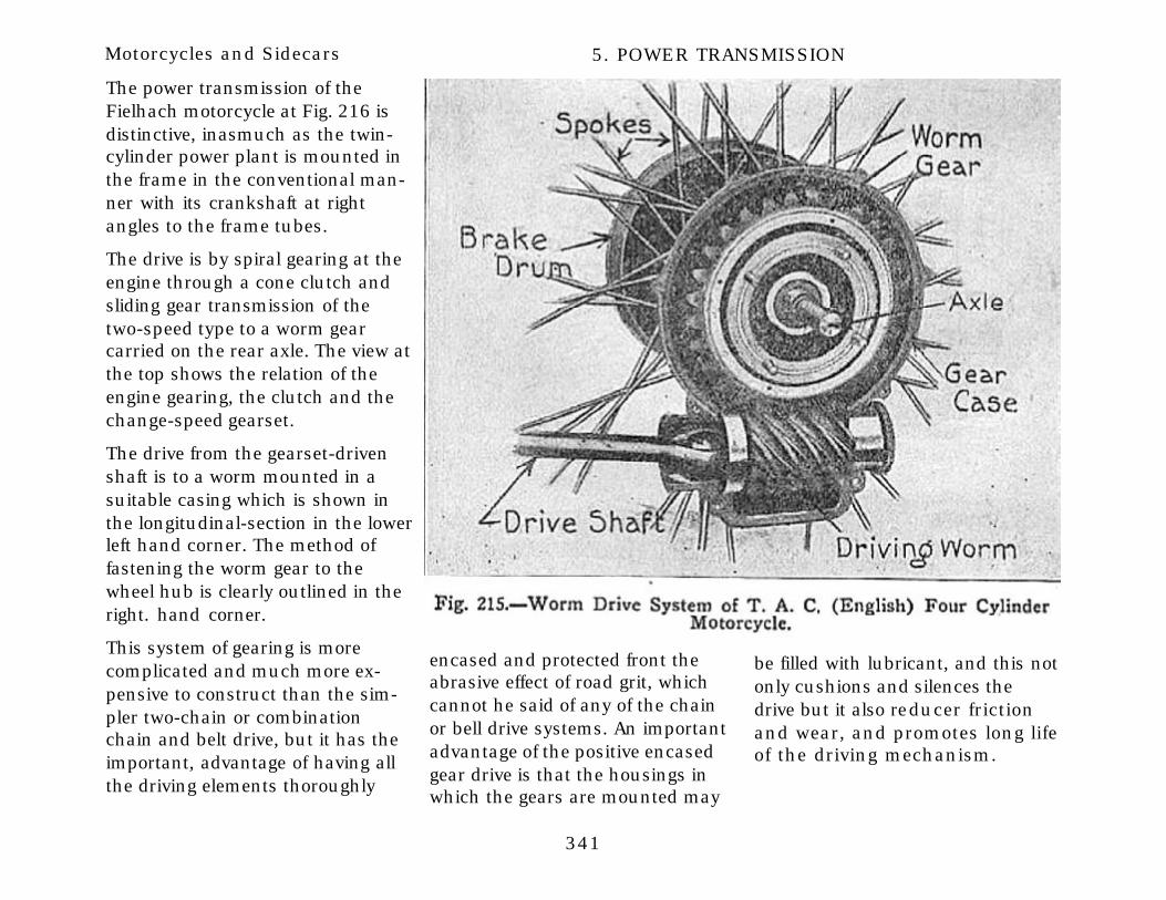
341
Motorcycles and Sidecars 5. POWER TRANSMISSION
The power transmission of theFielhach motorcycle at Fig. 216 isdistinctive, inasmuch as the twin-cylinder power plant is mounted inthe frame in the conventional man-ner with its crankshaft at rightangles to the frame tubes.
The drive is by spiral gearing at theengine through a cone clutch andsliding gear transmission of thetwo-speed type to a worm gearcarried on the rear axle. The view atthe top shows the relation of theengine gearing, the clutch and thechange-speed gearset.
The drive from the gearset-drivenshaft is to a worm mounted in asuitable casing which is shown inthe longitudinal-section in the lowerleft hand corner. The method offastening the worm gear to thewheel hub is clearly outlined in theright. hand corner.
This system of gearing is morecomplicated and much more ex-pensive to construct than the sim-pler two-chain or combinationchain and belt drive, but it has theimportant, advantage of having allthe driving elements thoroughly
encased and protected front theabrasive effect of road grit, whichcannot he said of any of the chainor bell drive systems. An importantadvantage of the positive encasedgear drive is that the housings inwhich the gears are mounted may
be filled with lubricant, and this notonly cushions and silences thedrive but it also reducer frictionand wear, and promotes long lifeof the driving mechanism.

342
Motorcycles and Sidecars 5. POWER TRANSMISSION

343
Motorcycles and Sidecars 5. POWER TRANSMISSION
Relation of Engine Power to Gear RatioIn one of the earlier chapters the reason for supplying various gear ratios has been considered insome detail, and the importance of selecting that best adapted so the power of the engine will bedelivered most effectively is an important phase of motorcycle design. An engine may be geared toohigh, which means that it will have some difficulty in overcoming the resistance imposed by hills orbad roads but is very fast on the level. If a machine is geared too low, it will be a good hill climber butwill not operate at satisfactory speeds under good conditions unless the engine is run excessivelyfast, which would produce more rapid depreciation of the power plant.
The two tables appended are given to show the gear ratios recommended by engine builders for their differentmotor types. It is, of course, understood that the designer of the motorcycle will select the power plant of theproper capacity for the machine to which it is fitted. The first table is given by the makers of the Precision (En-glish) engines, various models of which have been illustrated in this work. The last table is especially valuable,as it shows not only the gear ratios but the road speeds obtained with various sprocket sizes and single andtwin engines. This table has been compiled by the F. W. Spacke Machine Company who make the De Luxemotors. Other tables and formulae to assist in figuring speed are also presented.
Riders will do well to remember that cycle engines are essentially high-speed engines, and should not be over-geared. The following table will give best results both from the point of view of flexibility and average speed:
Engine Type. Gear Ratio for Solo Riding. Gear Ratio for Sidecars, Top Goat.2-1/2 ! horsepower 5.5 :: 1 ----------2-3/4 horsepower 5.0 :: 1 ----------
3-3/4 horsepower 4.5 :: 1 5.5 :: 13-3/4 HP w/OHVs 4.0 :: 1 5.0 :: 1
4 horsepower twin 4.5 :: 1 5.0 :: 1
Oreen model 4.0 :: 1 5.0 :: 14-1/4 horsepower 4.5 :: 1 5.0 :: 1
6 and 8 HP twin models 4.0 :: 1 4.5 :: 1

344
Motorcycles and Sidecars 5. POWER TRANSMISSION

345
Motorcycles and Sidecars 5. POWER TRANSMISSION
The point of highest efficiency and horsepower development is represented at approximately 2,500revolutions per minute, on standard stock motors, and is, for that reason, taken as a basis for esti-mating gear ratios. The above does not, therefore, necessarily represent the extreme maximum ofspeed that may be obtained from any gear ratio.
SPEED FORMULA.
To reduce A miles in B seconds to chiles per hour,
A x 3,600 / B = miles per hour.
SPEED EQUIVALENT’S IN AMERICAN AND FRENCH MEASUREMENTS.
1 mile per hour = 88 feet per minute= 1.46 feet per second.
= 27.8 meters per minute.= 0.463 meter per second.
1 kilometer per hour = 0.62.1 miles per hour.= 54.9 feet per minute.
= 0.91.1 meter per second.
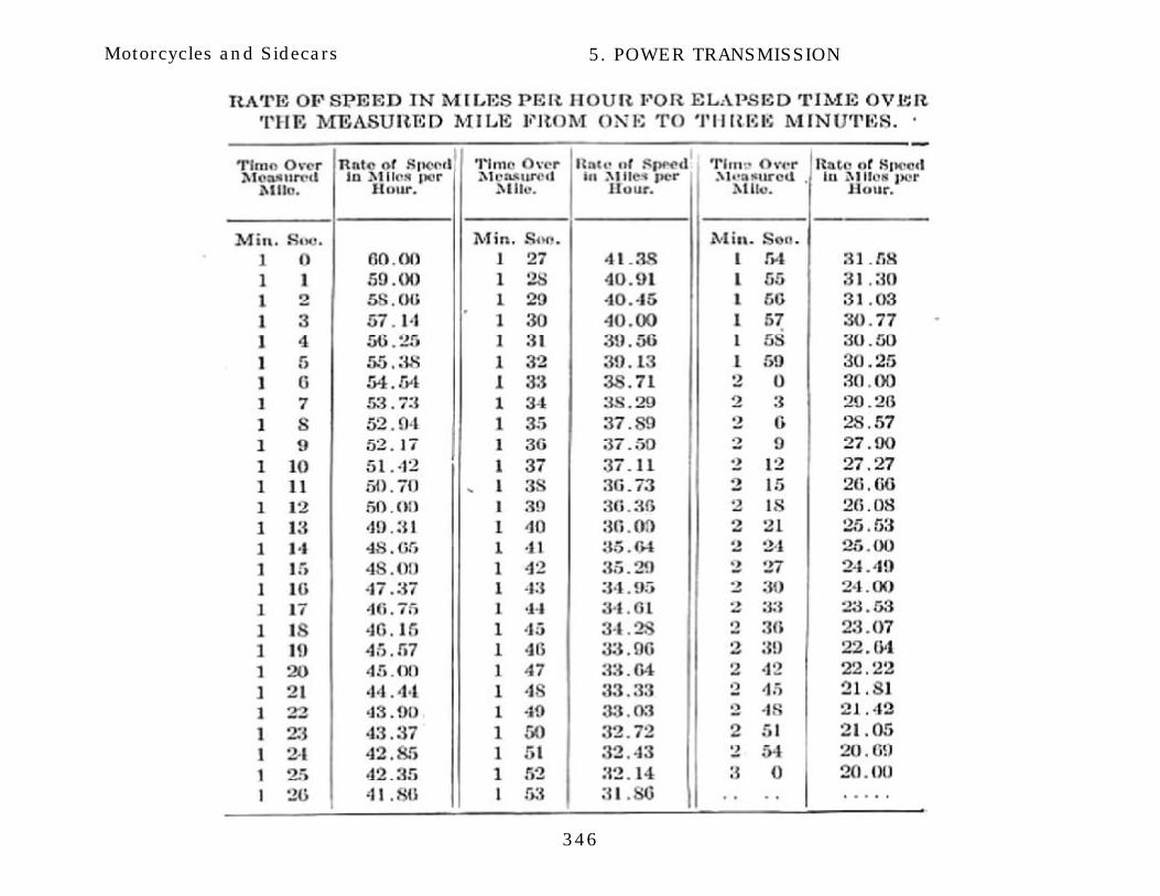
346
Motorcycles and Sidecars 5. POWER TRANSMISSION