Embed Size (px)
Citation preview
MOTORED TEST RIG DESIGN AND FABRICATION
FOR SMALL ENGINE TESTING
HO RUI JIN
A report submitted in partial fulfilment of the
requirement for the award of the
Diploma of Mechanical Engineering
Faculty of Mechanical Engineering
Universiti Malaysia Pahang
NOVEMBER 2007
ABSTRACT
Performance of a two-stroke engine is largely dependant on scavenging and
trapping efficiency of a designed cylinder and port geometry. A motored test rig built
specifically for high speed application is designed for 2-stroke spark ignition engine
to allow further study and have better understanding of flow mechanism of the
engine at high speed condition which will influence trapping and scavenging
efficiency. A new concept and design is developed. Current available test rig in
University Malaysia Pahang is limited to a low speed range of maximum of 1480rpm
which is the main constraint to further experiment and understanding. A rigid
designed test rig to allow assembly of small two-stroke engine, gearbox and
induction motor and amplify induction motor rotating speed to provide wide RPM
output using gearbox to provide a predetermined condition of operating two-stroke
cycle engine to allow data acquisition on condition boundary for CFD simulation and
experimental data. This new design of motored test rig will have the capability of
testing engine at high speed by assembling a gearbox to multiply the speed of driving
electric motor shaft of 1480 rpm into transmission input shaft to a maximum speed
over 6000rpm at the transmission output shaft. Under motored condition, pressure
transducer is applied and flush mounted at inlet port, scavenge port and cylinder. A
crank encoder is used to define the condition to each crank angle of a rotation. As a
result, data can be collected over a broader engine speed from data acquisition
computer.
vi

ABSTRAI(
Keupayaan sesebuah enjin dua lejang amat bergantung kepada kecekapan
"scavenging" dan "trapping" sesebuah design geometri port dan silinder. Sebuah
radas menguji yang ditujah motor dibuat khas untuk menguji kecekapan yang
dinyatakan sebuah enjin dua lejang nyalaan pencucuh dalam aplikasi keadaan
kelajuan tinggi untuk membenarkan kajian yang Iebih teliti untuk kefahaman yang
lanjut tentang mekanisme pengaliran udaran pada kelajuan tinggi dimana dipercayai
akan mempengaruhi kecekapan "scavenging" dan "trapping". Satu konsep dan
design radas menguji dibina dan diperkembangkan. Radas yang sedia ada di
Universiti Malaysia Pahang terhad kepada kelajuan yang rendah iaitu kelajuan
maksimum 1480 putaran seminit batasan utama untuk kajian dan kefaharnan lanjut.
Radas yang dibina mempunyai ciri seperti kukuh untuk proses pemasangan
komponen-komponen seperti enjin diuji, motor elektrik, kotak gear dan kelajuan
putaran elektrik motor ditambah dengan menggunakan kotak gear untuk kelajuan
putaran yang lebar untuk menyediakan keadaan yang ditentukan lebih awal untuk
operasi kitar enjin dua lejang untuk proses memperolehi data untuk simulasi CFD
dan data eksperimen. Radas menguji mi mempunyai keupayaan untuk menguji enjin
pada kelajuan putaran yang tinggi dengan menggunakan kotak gear untuk
menambahkan kelajuan yang dikeluarkan motor elektrik kepada kelajuan maksimum
6000 putaran seminit. Dalam keadaan yang dikilas, transducer tekanan dipasang
pada bukaan penyalur, bukaan "scavenge" dan dalam silinder. Encoder engkol
digunakan untuk menentukan keadaan setiap darjah putaran engkol. Sebagai
keputusan, data boleh diperolehi dari berbagai kelajuan melalui komputer pencatat
data.
vii

TABLE OF CONTENTS
viii
TITLE PAGE
TITLE PAGE i
SUPERVISOR DECLARATION
DECLARATION
DEDICATION iv
ACKNOWLEDGEMENTS v
ABSTRACT vi
ABSTRAK vii
TABLE OF CONTENTS viii
LIST OF TABLES xi
LIST OF FIGURES xii
LIST OF APPENDICES xiv
LIST OF ABBREVIATIONS xv
CHAPTER
1 INTRODUCTION 1
1.1 Introduction Two Stroke Engine 1
1.2 Background of Project 2
1.3 Problem Statement 3
1.4 Objectives 3
1.5 Scopes 3
1.6 Project Organization 4
2 LITERATURE REVIEW 6
2.1 Introduction 6
2.2 Introduction to Internal Combustion Engine 6

ix
2.2.1 The Otto Engine - Four Stroke Cycle 7
2.2.2 The Two-Stroke Engine 8
2.3 Experimental Methods for Quantifying Scavenging
Process 11
2.3.1 Measurement in Motored Engines 12
2.3.1.1 Static Model Test 12
2.3.1.2 Dynamic Model Test 13
2.4 Sources of Test-Stand and Test-Rig Design Literature
Review 14
2.4.1 Intake Flow Behaviour in a Motored and Fired
Two Stroke Research Engine 15
2.4.1.1 Experimental = LDV Setup 15
2.4.1.2 Experiment - Pressure Measurement 16
2.4.1.3 Experiment - Engine Control and Data
Acquisition 16
2.4.2 Cold Engine Testing 17
2.4.3 Portable Engine Test Stand 18
2.4.4 Stand and Support for Small Engine 19
2.4.5 Numerical Analysis of In-Cylinder Process for
Small Two-Stroke Spark Ignition (SI) Engine 20
2.5 Summary of Literature Review 22
3 METHODOLOGY 23
3.1 Introduction 23
3.2 Overall Methodology 24
3.3 Schematic Diagram 25
3.4 Determining Required Component 26
3.4.1 AC Induction Motor 26
3.4.2 3-Phase Inverter 27
3.4.3 Two-Stroke Engine 28
3.4.4 Data Acquisition System 29
3.4.4.1 DEWE-5000 Combustion Analyzer 30
X
3.4.4.2 Crank Encoder 31
3.4.4.3 Pressure Transducer 32
3.5 Conceptualization and Concept Selection 33
3.6 Fabrication 34
3.7 Conclusion 35
4 RESULTS AND DISCUSSION 36
4.1 Introduction 36
4.2 Test-rig Part List 36
4.3 Fabricated Part 37
4.4 Assembly Process 39
4.5 Experimental Setup and Procedures 41
4.5.1 Experimental Conditions 41
4.5.2 Experimental Procedures 41
5 CONCLUSION AND RECOMMENDATIONS. 43
5.1 Introduction 43
5.2 Conclusion 43
5.3 Recommendations 44
REFERENCES 45
APPENDICES 46-57
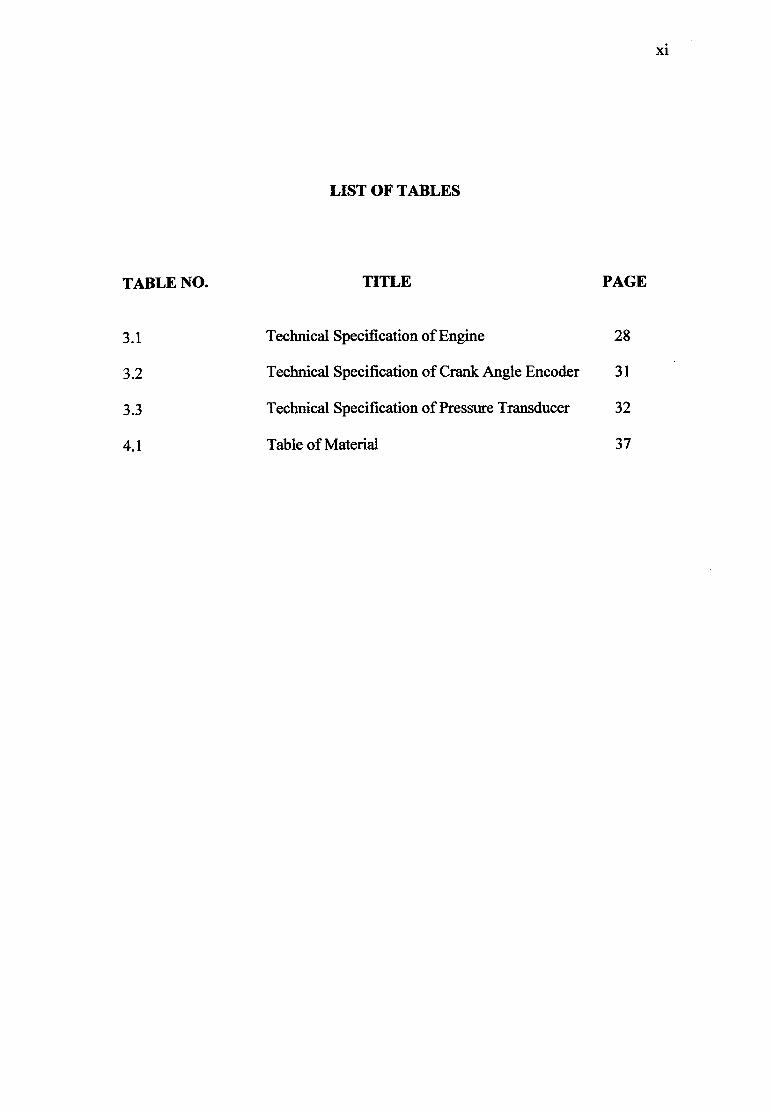
LIST OF TABLES
TABLE NO. TITLE PAGE
3.1 Technical Specification of Engine 28
3.2 Technical Specification of Crank Angle Encoder 31
3.3 Technical Specification of Pressure Transducer 32
4.1 Table of Material 37
xi

LIST OF FIGURES
FIGURE NO. TITLE PAGE
2.1 Two-stroke cycle event 9
2.2 Cold engine test setup 18
2.3 Side and top view of engine test stand 19
2.4 Small engine test stand 20
2.5 Schematic diagram for Numerical Analysis
of In-Cylinder Process for Small Two-Stroke
Spark-Ignition (SI) Engine 21
3.1 Flowchart of overall methodology 24
3.2 Schematic diagram for test-rig setup 25
3.3 3 phase AC induction motor 26
3.4 Yaskawa Juspeed-F P300 inverter 27
3.5 A basic three phase inverter control scheme 27
3.6 Tanika BG-328A 28
3.7 Data acquisition setup 29
3.8 Pressure transducer 32
3.9 Concept drawing 33
3.10 Drawing of fabricated part 33
3.11 A cut 2" by 2" tubular mild steel 34
3.12 Material cut into dimension with drilled holes 35
4.1 The part fabricated 38
xli

xlii
4.2 Worm gearbox
[I]
4•3 Assembled test-rig 40
LIST OF APPENDICES
APPENDIX TITLE PAGE
A Gannt Chart 46
B Technical Drawings 47-57
xiv

LIST OF ABBREVIATION
DAQ Data Acquisition System
LDV Laser Doppler Velociinetri
TDC Top Dead Center
BDC Bottom Dead Center
SMAW Shielded Metal Arc Welding
MIG Metal Inert Gas
AC Alternate Current
1MEP Internal Mean Effective Pressure
xv

CHAPTER 1
INTRODUCTION
Li Introduction Two-Stroke Cycle
The two stroke cycle is not new concept where automotive or power
generation engines developed before Nicolaus Otto who invented the four stroke
cycle engine in 1876 operated on a two-stoke cycle [Heywood, 1988]. Today, the
two-stroke engine is a refined power unit that offers high performance while being
compact, simple and lightweight.
The cycle begins by compression stroke which starts by closing the inlet and
exhaust ports, and then compressed the cylinder contents and draws fresh charge
into the crankcase. As the piston approaches top center, combustion is initiated
either by spark ignition or compression ignition. The following stroke known as
power stroke or expansion stroke, which starts with the piston at top center and
ends at bottom center as the high temperature, high-pressure, gases push the piston
down until piston approaches bottom center when first the exhaust ports and then
the intake ports are uncovered. Most of the burnt gases exit the cylinder in an
exhaust blowdown process. When the transfer port are uncovered, the fresh charge
which has been compressed in the crankcase flows into the cylinder to start another
cycle.
One power stroke per revolution. Doubling the number of power strokes per
unit time relative to the four-stroke cycle increases the power output per unit
displaced volume. It does not however increase by a factor of 2. The outputs of
two-stroke engines range from only 20% to 60% above those of equivalent-size

2
four-stroke units (Blair, 1996). This lower increase in practice is a result of the
poorer than ideal charging efficiency that is incomplete filling of the cylinder
volume with fresh air.
1.2 Background of the Project
The flow processes of intake, compression, and exhaust of two stroke
engine are all conducted in an unsteady manner (Blair, 1996). A flow is defined
unsteady gas flow is where pressure, temperature and gas particle is a pipe or duct
varies with time constant (Blair, 1996). As gas flow motions in a two-stroke engine
directly control the performance characteristic of the engine, designers are required
to understand the flow mechanism thoroughly of an engine after designing.
A motored test rig specifically for high speed application is to be design for
2-stroke spark ignition engine to allow us to further study and have better
understanding of flow mechanism of the engine at high speed condition. Current
available test rig in University Malaysia Pahang is limited to a low speed range of
maximum of 1480 rpm which is the main constraint to further experiment and
understanding. This new design of motored test rig will have the capability of
testing engine at high speed by assembling a transmission to multiply the speed of
driving electric motor shaft of 1480 rpm into transmission input shaft to a
maximum speed over 6000 rpm at the transmission output shaft. As a result, data
can be collected over a broader engine speed from data acquisition computer.
The design of the motored test rig should be compact and applicable on
various 2-stroke engine designs and made of strong and light weight material like
alloyed steel. The setup of the motored test rig should be easy and requires as little
tool as possible. Each component will be fitted and assembled as rigid as possible
as juddering and severe vibration maybe cause component to loosen. It will be
dangerous if a component got lose during the experiment is carried out in high
speed.
3
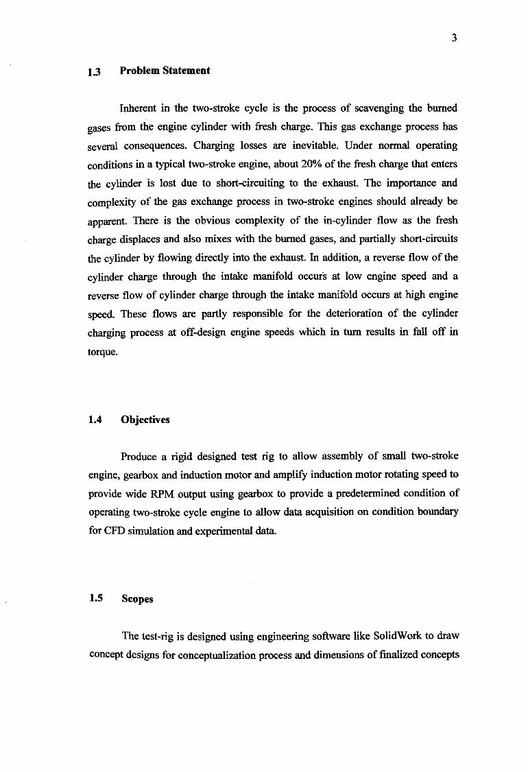
1.3 Problem Statement
Inherent in the two-stroke cycle is the process of scavenging the burned
gases from the engine cylinder with fresh charge. This gas exchange process has
several consequences. Charging losses are inevitable. Under normal operating
conditions in a typical two-stroke engine, about 20% of the fresh charge that enters
the cylinder is lost due to short-circuiting to the exhaust. The importance and
complexity of the gas exchange process in two-stroke engines should already be
apparent. There is the obvious complexity of the in-cylinder flow as the fresh
charge displaces and also mixes with the burned gases, and partially short-circuits
the cylinder by flowing directly into the exhaust. In addition, a reverse flow of the
cylinder charge through the intake manifold occurs at low engine speed and a
reverse flow of cylinder charge through the intake manifold occurs at high engine
speed. These flows are partly responsible for the deterioration of the cylinder
charging process at off-design engine speeds which in turn results in fall off in
torque.
1.4 Objectives
Produce a rigid designed test rig to allow assembly of small two-stroke
engine, gearbox and induction motor and amplify induction motor rotating speed to
provide wide RPM output using gearbox to provide a predetermined condition of
operating two-stroke cycle engine to allow data acquisition on condition boundary
for CFD simulation and experimental data.
1.5 Scopes
The test-rig is designed using engineering software like SolidWork to draw
concept designs for conceptualization process and dimensions of finalized concepts
4
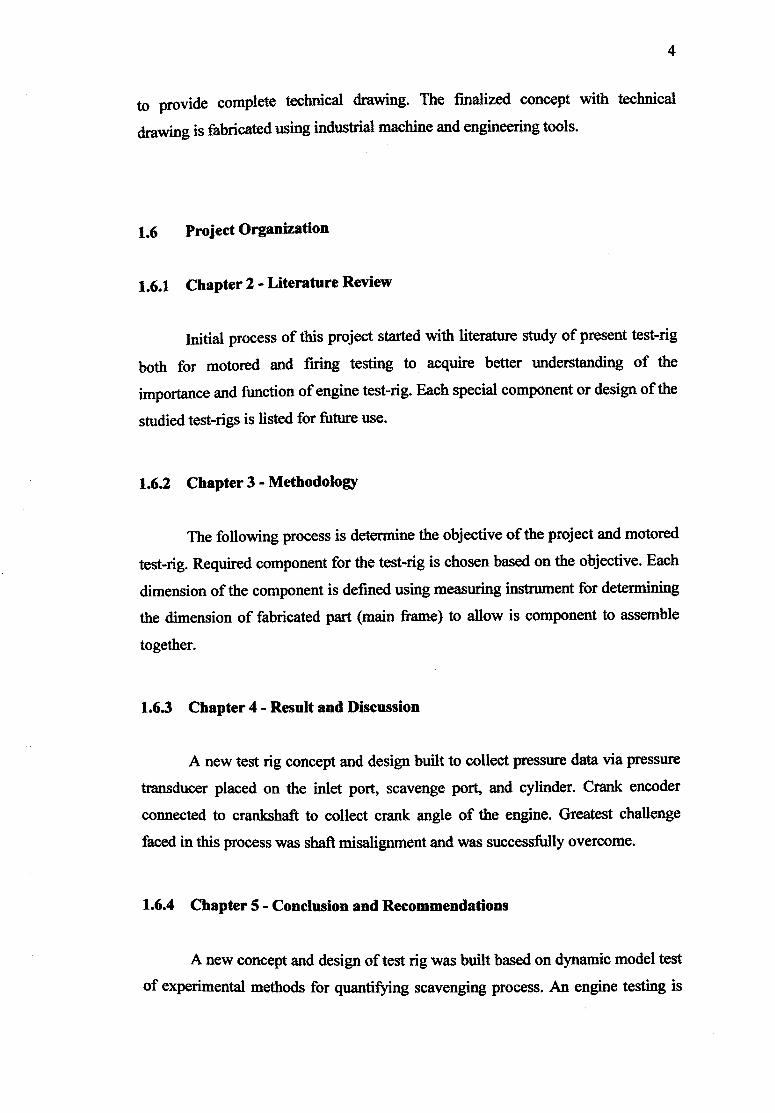
to provide complete technical drawing. The finalized concept with technical
drawing is fabricated using industrial machine and engineering tools.
1.6 Project Organization
1.6.1 Chapter 2 - Literature Review
initial process of this project started with literature study of present test-rig
both for motored and firing testing to acquire better understanding of the
importance and function of engine test-rig. Each special component or design of the
studied test-rigs is listed for future use.
1.6.2 Chapter 3- Methodology
The following process is determine the objective of the project and motored
test-rig. Required component for the test-rig is chosen based on the objective. Each
dimension of the component is defined using measuring instrument for determining
the dimension of fabricated part (main frame) to allow is component to assemble
together.
1.6.3 Chapter 4- Result and Discussion
A new test rig concept and design built to collect pressure data via pressure
transducer placed on the inlet port, scavenge port, and cylinder. Crank encoder
connected to crankshaft to collect crank angle of the engine. Greatest challenge
faced in this process was shaft misalignment and was successfully overcome.
1.6.4 Chapter 5- Conclusion and Recommendations
A new concept and design of test rig was built based on dynamic model test
of experimental methods for quantifying scavenging process. An engine testing is

5
recommended to study engine flow characteristic and collect boundary condition
data can be carried out for CFD simulation later. This data will allow further
investigation of two-stroke engine scavenging characteristic to improve exhaust
emission and fuel consumption.

CHAPTER 2
LITERATURE REVIEW
2.1 Introduction
This chapter will provide detail description of literature review done
regarding the project title of motored test-rig design and fabrication for small
engine testing. In this literature review, it started with the functions and
fundamentals of internal combustion engine and also the variant. Definition of
internal combust is defined in the first topic. In the following topic, the popular four
stroke cycle or more commonly known as Otto cycle is briefly discussed along with
basic understanding of the four-stroke engine operation together with innovation of
Otto cycle is the better designed 2-stroke engine is discussed in detail as the test-rig
is targeted to cater of this kind of engine. Some study on experimental method of
quantifying scavenging process revealed categories of tests that had been done to
collect valuable data. Final topic in this chapter is mostly about different types of
test setup that maybe relevant topic the project title.
2.2 Introduction to Internal Combustion Engine
Generally, combustion engines are a device that converts chemical energy
contained in the fuel to mechanical power. There are two types of combustion
engine which are external combustion engine and internal combustion engine in
which internal combustion engines are distinct from external combustion engines
where energy is released by burning or oxidizing the fuel inside the engine either by

7
spark ignition or Compression ignition. The fuel-air mixture before combustion and
the burned products after combustion are the actual working fluids. The work
transfers which provide the desired power output occur directly between these
working fluids and the mechanical components of the engine. However, the gas
turbine is also by this definition is an internal combustion engine. Conventionally,
the term is used for spark ignition and compression ignition engines. The operating
principles of gas turbines are fundamentally different, and they are not discussed.
According to unpublished French patent issued in 1862 to Alphonse Beau
de Rochas, maximum efficiency in an internal combustion engine could be
achieved with combination o largest possible cylinder volume with minimum
boundary surface, greatest possible working speed, greatest possible expansion ratio
and greatest possible pressure at the beginning of expansion (Heywood, 1988). The
first two conditions hold heat losses form the charge to a minimum, the third
condition recognizes that the greater the expansion of the post combustion gases,
the greater the work extracted and the fourth condition recognizes that higher initial
pressures make greater expansion possible and give higher pressures throughout the
process both resulting greater work transfer.
2.2.1 Otto Engine - Four Stroke Cycle
The majority of reciprocating engines operate on what is known as the four-
stroke cycle often called the Otto cycle after its inventor Nicolaus Otto who built
the first engine operating on these principles in 1876 (Heywood, 1988). Each
cylinder requires four strokes of its piston - two revolutions of the crankshaft to
complete the sequence of the events which produces one power stroke. The
sequence of events required to produce a power stroke start with the intake stroke
followed by compression stroke, power stroke and finally exhaust stroke. An intake
stroke, which starts with the piston at top center and ends with the piston at bottom
center draws fresh charge into the cylinder. To increase the mass inducted, the inlet
valve opens shortly before the stroke starts and closes after it ends.

8
A compression stroke takes place when both intake and exhaust valve
closed and the mixture inside the cylinder is compressed to a small fraction of its
initial volume. Toward the end of the compression stroke, combustion is initiated
and the cylinder pressure rises rapidly. A power stroke or expansion stroke, which
starts with the piston at top center and ends at bottom center as the high
temperature, high pressure, gases push the piston down and force the crank to
rotate. About five times as much work is done on the piston during the power stroke
as the piston had to do during compression. As the piston approaches bottom center,
the exhaust valve opens to initiate the exhaust process and drop the cylinder
pressure to close to the exhaust pressure. An exhaust stroke where the remaining
burned gases exit the cylinder because the cylinder pressure maybe substantially
higher than the exhaust pressure and as they are swept out by the piston as it moves
toward top center. The exhaust valve opens as the piston approaches top center and
closes just after top center and the cycles continue.
The four-stroke cycles requires two crankshaft revolution of each cylinder
for each power stroke. To obtain a higher power output from a given engine size,
and a simpler valve design, the two-stroke cycle was developed.
2.2.2 Two-Stroke Engine
Further development followed fast once the full impact of what Otto had
achieved became apparent. By 1880s several engineers (e.g. Dugald Clerk, 1854-
19 and James Robson, 1833-1913, in England and Karl Benz, 1844-1929, in
Germany) had successfully developed two-stroke internal combustion engines
where the exhaust stroke and intake processes occur during the end of the power
stroke and the beginning of the compression stroke (Heywood, 1988).
As the two-stroke cycle lacks separate intake and exhaust strokes, a
scavenging pump is required to drive the fresh charge into the cylinder. In one of
the simples and most frequently used types of two-stroke engine designs, the

bottom surface of the piston in conjunction with that portion of the crankcase
beneath each cylinder is used as the scavenging pump.
EXHAUST
INTAKE PORT
PORT
INTAKE
PORT
2 LN,3 M-1 1 "'W Ab^^EXHAUST
tNT INTAKE 'F ' PORT
TRANSFER PORT
10 CO
Fzk_^
141
Figure 2.1: Two-stroke cycle event (Dave Mann, 2000)
The cycle begins while the piston is traveling upward toward the top center
crank position, and the crankcase intake port is uncovered by the piston. Fresh
charge enters into the crankcase through the intake manifold while the charge
within the cylinder continues to be compressed by the upper part of the piston. The
charge is then ignited either by and electrical discharge in a spark-ignition engine or
by a spontaneous ignition process in diesel, combustion occurs and the burned
gases in the cylinder expand as the piston travels toward bottom center. At the same
time, as the crankcase volume decreases and the intake port is still open, some of
the fresh charge may escape to the atmosphere through the intake port is still open,
some of the fresh charge may escape to the atmosphere through the intake manifold
in a reverse flow. Approximately 60° after top center, the inlet port closes and the
fresh mixture in the crankcase is then compressed (Sher, 1999). The in-cylinder gas
exchange process begins as the exhaust port is opened. As the piston continues its
downward travel, it then opens scavenge or transfer ports. When both scavenge or
transfer port and exhaust ports are open, the cylinder is subjected to a pressure
10
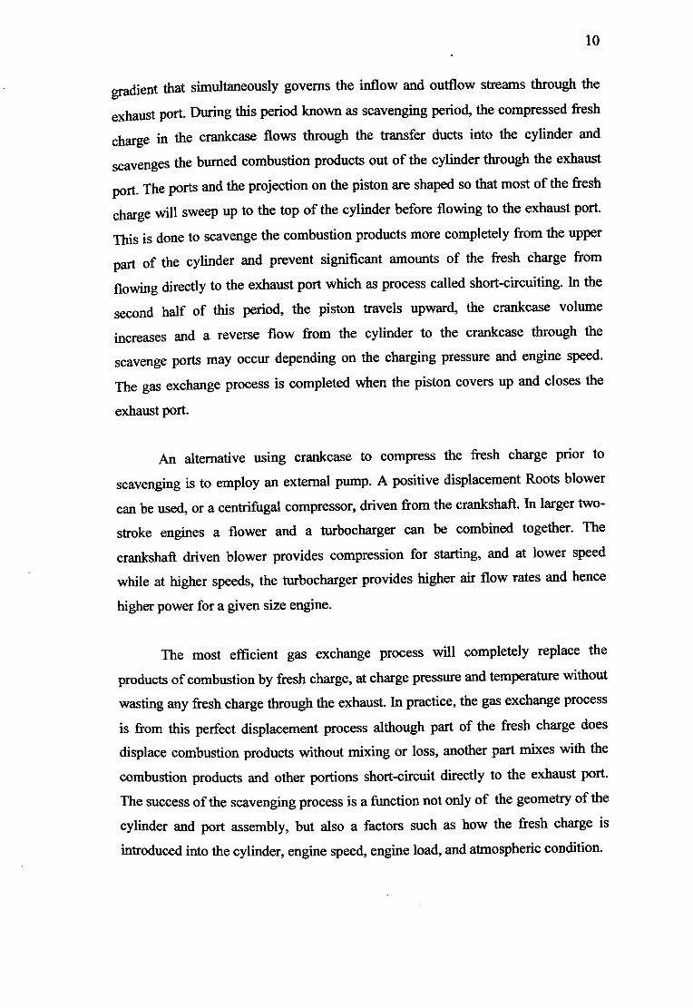
gradient that simultaneously governs the inflow and outflow streams through the
exhaust port. During this period known as scavenging period, the compressed fresh
charge in the crankcase flows through the transfer ducts into the cylinder and
scavenges the burned combustion products out of the cylinder through the exhaust
port. The ports and the projection on the piston are shaped so that most of the fresh
charge will sweep up to the top of the cylinder before flowing to the exhaust port.
This is done to scavenge the combustion products more completely from the upper
part of the cylinder and prevent significant amounts of the fresh charge from
flowing directly to the exhaust port which as process called short-circuiting. In the
second half of this period, the piston travels upward, the crankcase volume
increases and a reverse flow from the cylinder to the crankcase through the
scavenge ports may occur depending on the charging pressure and engine speed.
The gas exchange process is completed when the piston covers up and closes the
exhaust port.
An alternative using crankcase to compress the fresh charge prior to
scavenging is to employ an external pump. A positive displacement Roots blower
can be used, or a centrifugal compressor, driven from the crankshaft. In larger two-
stroke engines a flower and a turbocharger can be combined together. The
crankshaft driven blower provides compression for starting, and at lower speed
while at higher speeds, the turbocharger provides higher air flow rates and hence
higher power for a given size engine.
The most efficient gas exchange process will completely replace the
products of combustion by fresh charge, at charge pressure and temperature without
wasting any fresh charge through the exhaust. In practice, the gas exchange process
is from this perfect displacement process although part of the fresh charge does
displace combustion products without mixing or loss, another part mixes with the
combustion products and other portions short-circuit directly to the exhaust port.
The success of the scavenging process is a function not only of the geometry of the
cylinder and port assembly, but also a factors such as how the fresh charge is
introduced into the cylinder, engine speed, engine load, and atmospheric condition.

11
2.3 Experimental Methods For Quantifying Scavenging Process
The performance of a two-stroke engine is strongly dependant on how well
the burnt gases are scavenged from the cylinder volume and replaced with fresh
charge which is on the efficiency of the scavenging process and on the amount of
fresh charge trapped inside the cylinder at the end of the process (Sher, 1999). For.
the same pumping power input, a cylinder that is better scavenged will produce a
higher engine brake power. Improved scavenging will minimize losses of fresh
charge to the exhaust port through short-circuiting and therefore in engines with
premixed charge will reduce fuel consumption and hydrocarbon emissions. Lower
fuel consumption at low engine load can also be achieved with a well-controlled
scavenging process, often with appropriate stratification of the fresh charge within
the cylinder to facilitate good combustion under lean and/or high residual gas
operating conditions.
The characteristics of the scavenging process, that is the scavenging flow
details, its overall efficiency, and the distribution of the charge retained in the
cylinder at the end of the process, depend very much on the operating condition of
the engine. Important parameters are the engine speed, engine load, and ambient
conditions. For example, the typical convex shape of the torque versus engine-
speed curve is often attributed to the sensitivity of the scavenging efficiency to
engine speed. Also, the scavenging flow behavior in two-stroke engine employing a
Schnurle-type scavenging system, is strongly dependant on ambient conditions,
which limits their suitability for high-altitude applications.
Therefore, it is important for the engine designer to obtain reliable
information about the engine's scavenging process over a wide range of operating
conditions. Due to its complexity, the scavenging flow behaviours cannot be
accurately predicted. So experimental measurements is although difficult to obtain,
are essential to engine development and design. As there is no direct method for
determining the mass of fresh charge trapped inside the cylinder at the
commencement of the compression process in a firing engine, several indirect
methods have been developed. These may be classified into two main categories:
measurements in motored engines and measurements in fired engines.
12
2.3.1 Measurement in Motored Engines
With motored engine tests it is presumed that the scavenging characteristics
are only weakly dependant on the combustion process (Sher, 1999). The engine
itself, or a model of the engine is driven by an external motor and the scavenging
process is then analyzed. For a preliminary design of engine geometry, it is
sometimes easiest to evaluate the scavenging characteristics on the basis of a single
cycle rather than several successive cycles. Static model test, in which the cylinder
is subjected to a steady air flow through it ports while the piston is locked at bottom
center are also used.
2.3.1.1 Static Model Test
Static or steady flow model tests are mainly used to study the flow direction
and distribution of the entering fresh charge, without introducing the effects of the
moving piston and the unsteady nature of the process on the scavenging
characteristic. Jante found that scavenging ports can be designed to give an efficient
scavenging process using a test on the engine with the cylinder head removed (Sher,
1999). Jante propose that the fresh charge be introduced to the cylinder as a steady
flow and that the velocity profile of the scavenging flow be measured just above the
open cylinder. He argues that to minimize port short circuiting, the upward flow
from the scavenge port toward that cylinder head should be concentrated on the
wall opposite the exhaust port. A zero velocity interface between upward and
downward streams should be located about halfway across the cylinder or slightly
farther from the exhaust side. The area of the interface available for turbulent
mixing between the two streams should be minimized if the zero velocity contour
appears on the diagram as a straight line perpendicular to the plane of geometrical
symmetry.
Although the coefficient of discharge of the scavenge port as well as the
inclination angle of the incoming charge depend on piston speed, piston position,
and pressure difference across the cylinder, steady flow model have been found to
be useful indicator of the effect of pressure ratio across the cylinder on the airflow
13
rate though the cylinder. Also, by comparing the profile of the axial velocity
component at two distinct cross sections of the cylinder, steady flow models have
also found valuable for estimating the fresh charge losses to the exhaust port (short-
circuiting)in loop and cross scavenging engines.
Steady flow methods are also a useful tool for visualizing key features of the
scavenging flow. An impression of the flow inside the cylinder with a particular
design of ports (and piston) maybe obtained by using simple flow visualization
technique. Although these steady flow engine and model test have been found
useful by many engine manufacturers as a first step in engine port geometry design,
the conclusion drawn form such test should be care fully examined for their
applicability to real engines for the following reasons (Sher, 1999):
1) The phenomena associated with scavenging process are unsteady
and can only be partially simulated by a steady flow process.
2) In the engine, the movement of the piston and the blowdown process
do affect various stages of the flow field inside the cylinder.
3) The velocity and the inclination angle of the incoming charge
depend on the piston speed, the piston position, and the pressure
difference across the cylinder that may vary with time.
2.3.1.2 Dynamic Model Test
Dynamic model tests are mainly used to investigate possible ways of
modifying a particular port geometry to improve its scavenging characteristics
(Sher, 1999). With this approach, the engine itself or a model of engine is driven by
an external motor, while the scavenging characteristics are evaluated by sampling,
visualizing or other measurement techniques. The experimental apparatus is usually
constructed so it provides an inexpensive means to obtain valuable design
information relative to the expense of a full prototype.
To obtain useful conclusions form an experimental simulation, the
experimental apparatus should be designed so that the proper relationships between