Embed Size (px)
Citation preview
Motorized ball valves with 3-wire control
6442 - 6443 series
Function
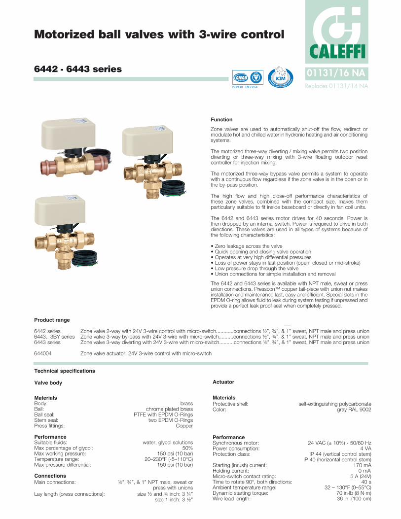
Zone valves are used to automatically shut-off the flow, redirect or modulate hot and chilled water in hydronic heating and air conditioning systems.
The motorized three-way diverting / mixing valve permits two position diverting or three-way mixing with 3-wire floating outdoor reset controller for injection mixing.
The motorized three-way bypass valve permits a system to operate with a continuous flow regardless if the zone valve is in the open or in the by-pass position.
The high flow and high close-off performance characteristics of these zone valves, combined with the compact size, makes them particularly suitable to fit inside baseboard or directly in fan coil units.
The 6442 and 6443 series motor drives for 40 seconds. Power is then dropped by an internal switch. Power is required to drive in both directions. These valves are used in all types of systems because of the following characteristics:
• Zero leakage across the valve• Quick opening and closing valve operation• Operates at very high differential pressures• Loss of power stays in last position (open, closed or mid-stroke)• Low pressure drop through the valve• Union connections for simple installation and removal
The 6442 and 6443 series is available with NPT male, sweat or press union connections. Presscon™ copper tail-piece with union nut makes installation and maintenance fast, easy and efficient. Special slots in the EPDM O-ring allows fluid to leak during system testing if unpressed and provide a perfect leak proof seal when completely pressed.
Product range
6442 series Zone valve 2-way with 24V 3-wire control with micro-switch............connections ½”, ¾”, & 1” sweat, NPT male and press union6443.. 3BY series Zone valve 3-way by-pass with 24V 3-wire with micro-switch..........connections ½”, ¾”, & 1” sweat, NPT male and press union6443 series Zone valve 3-way diverting with 24V 3-wire with micro-switch..........connections ½”, ¾”, & 1” sweat, NPT male and press union
644004 Zone valve actuator, 24V 3-wire control with micro-switch
Technical specifications
Valve body
Materials Body: brass Ball: chrome plated brassBall seal: PTFE with EPDM O-Rings Stem seal: two EPDM O-RingsPress fittings: Copper
PerformanceSuitable fluids: water, glycol solutionsMax percentage of glycol: 50%Max working pressure: 150 psi (10 bar)Temperature range: 20–230°F (-5–110°C)Max pressure differential: 150 psi (10 bar)
Connections Main connections: ½”, ¾”, & 1” NPT male, sweat or
press with unionsLay length (press connections): size ½ and ¾ inch: 3 ¼”
size 1 inch: 3 ½”
Actuator
MaterialsProtective shell: self-extinguishing polycarbonateColor: gray RAL 9002
PerformanceSynchronous motor: 24 VAC (± 10%) - 50/60 HzPower consumption: 4 VAProtection class: IP 44 (vertical control stem)
IP 40 (horizontal control stem)Starting (inrush) current: 170 mAHolding current: 0 mAMicro-switch contact rating: 5 A (24V)Time to rotate 90°, both directions: 40 sAmbient temperature range: 32 – 130°F (0–55°C)Dynamic starting torque: 70 in·lb (8 N·m)Wire lead length: 36 in. (100 cm)
Replaces 01131/14 NA
CALEFFI01131/16 NA
ISO 9001 No. 0003
ACCREDITED
ISO 9001 FM 21654

Dimensions
2 3/16”
D
C
A
B
A
C
A A
DA
B
E
D
A A
EAB
F
D
A A
AB
F
C
A A
A
B
E
3 ¾”C
3 7 /
16”
A
2 3/8”
B
A
CALEFFI
A B
AB
A B
AB
CALEFFI
2 3/8”
3 7 /
16”
3 ¾”
3 ¾”3 ¾”
3 7 /
16”
3 7 /
16”
2 3/8” 2 3/8”
2 3/16”
3 ¾” 3 ¾” 2 3/16”
3 7 /
16”
3 7 /
16”
CC
A B
AB
49
63
A B
AB
49
63
6442 series 2-way
6443.. 3BY code,3-way by-passversion
Actuator is in OPEN position with brown wire powered.
Actuator is in CLOSED position with black wire powered.
Code A B C DWt (lb)
644249A ½" sweat 3 7⁄8" 2 3⁄8" 1 7⁄16” 2.3
644259A ¾" sweat 4 7⁄16" 2 3⁄8" 1 7⁄16” 2.3
644269A 1" sweat 5 9⁄16" 2 3⁄8" 1 ½” 2.3
644246A ½" press 4 ¾" 2 3⁄8" 1 7⁄16” 2.4
644256A ¾" press 4 ¾" 2 3⁄8" 1 7⁄16” 2.4
644266A 1" press 5 ¼" 2 3⁄8" 1 ½” 2.4
644240A ½" NPT 4 5⁄8" 2 3⁄8" 1 7⁄16” 2.3
644250A ¾" NPT 4 5⁄8" 2 3⁄8" 1 7⁄16” 2.3
644260A 1" NPT 5 ¼" 2 3⁄8" 1 ½” 2.3
2 3/16”
D
C
A
B
A
C
A A
DA
B
E
D
A A
EAB
F
D
A A
AB
F
C
A A
A
B
E3 ¾”
C3
7 /16
”A
2 3/8”
BA
CALEFFI
A B
AB
A B
AB
CALEFFI
2 3/8”
3 7 /
16”
3 ¾”
3 ¾”3 ¾”
3 7 /
16”
3 7 /
16”
2 3/8” 2 3/8”
2 3/16”
3 ¾” 3 ¾” 2 3/16”
3 7 /
16”
3 7 /
16”
CC
Code A B C D EWt (lb)
644349A 3BY ½" sweat 4 5⁄8" 2 3⁄8" 1 7⁄16” 2 5⁄16” 2.5
644359A 3BY ¾" sweat 4 5⁄8” 2 3⁄8" 1 7⁄16” 2 5⁄16” 2.5
644369A 3BY 1" sweat 5 ¼” 2 3⁄8" 1 ½” 2 5⁄8” 2.5
644346A 3BY ½" press 4 ¾" 2 3⁄8" 1 7⁄16” 2 ½” 2.6
644356A 3BY ¾" press 5 1⁄16” 2 3⁄8" 1 7⁄16” 3 1⁄8” 2.6
644366A 3BY 1" press 5 ¼" 2 3⁄8" 1 ½” 2 5⁄8” 2.6
644340A 3BY ½" NPT 3 7⁄8" 2 3⁄8" 1 7⁄16” 1 7⁄8” 2.5
644350A 3BY ¾" NPT 4 7⁄16" 2 3⁄8" 1 7⁄16” 2 1⁄8” 2.5
644360A 3BY 1" NPT 5 9⁄16" 2 3⁄8" 1 ½” 2 ¾” 2.5
A B
AB
49
63
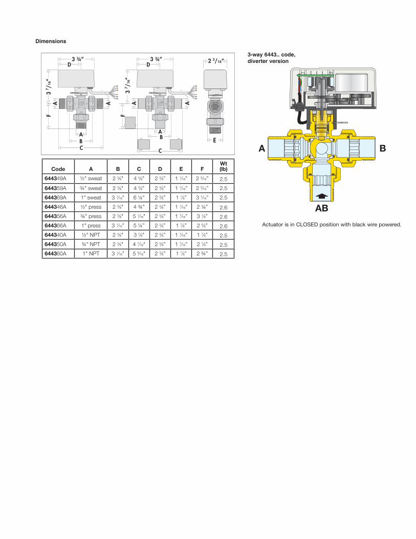
3-way 6443.. code, diverter version
Actuator is in CLOSED position with black wire powered.
Dimensions
2 3/16”
D
C
A
B
A
C
A A
DA
B
E
D
A A
EAB
F
D
A A
AB
F
C
A A
A
B
E
3 ¾”C
3 7 /
16”
A
2 3/8”
B
A
CALEFFI
A B
AB
A B
AB
CALEFFI
2 3/8”
3 7 /
16”
3 ¾”
3 ¾”3 ¾”
3 7 /
16”
3 7 /
16”
2 3/8” 2 3/8”
2 3/16”
3 ¾” 3 ¾” 2 3/16”
3 7 /
16”
3 7 /
16”
CC
Code A B C D E FWt (lb)
644349A ½" sweat 2 3⁄8" 4 5⁄8" 2 3⁄8” 1 7⁄16” 2 5⁄16” 2.5
644359A ¾" sweat 2 3⁄8" 4 5⁄8" 2 3⁄8" 1 7⁄16” 2 5⁄16” 2.5
644369A 1" sweat 3 1⁄16" 6 ¼" 2 3⁄8” 1 7⁄8” 3 1⁄16” 2.5
644346A ½" press 2 3⁄8" 4 ¾" 2 3⁄8” 1 7⁄16” 2 ¼” 2.6
644356A ¾" press 2 3⁄8" 5 1⁄16" 2 3⁄8” 1 7⁄16” 3 1⁄8” 2.6
644366A 1" press 3 1⁄16” 5 ¼” 2 3⁄8” 1 7⁄8” 2 5⁄8” 2.6
644340A ½" NPT 2 3⁄8" 3 7⁄8" 2 3⁄8” 1 7⁄16” 1 7⁄8” 2.5
644350A ¾" NPT 2 3⁄8" 4 7⁄16" 2 3⁄8” 1 7⁄16” 2 1⁄8” 2.5
644360A 1" NPT 3 1⁄16” 5 9⁄16" 2 3⁄8” 1 7⁄8” 2 ¾” 2.5
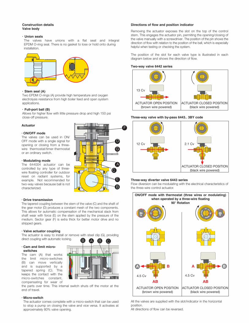
Directions of flow and position indicator
Removing the actuator exposes the slot on the top of the control stem. This engages the actuator pin, permiting the opening/closing of the valve manually with a screwdriver. The position of the pin shows the direction of flow with relation to the position of the ball, which is especially helpful when testing or checking the system.
The position of the slot for each valve type is illustrated in each diagram below and shows the direction of flow.
Two-way valve 6442 series
Three-way valve with by-pass 6443.. 3BY code
Three-way diverter valve 6443 series Flow diversion can be modulating with the electrical characteristics of the three-wire control actuator.
All the valves are supplied with the slot/indicator in the horizontal position.All directions of flow can be reversed.
ACTUATOR CLOSED POSITION (black wire powered)
Actuator
· ON/OFF mode The valves can be used in ON/OFF mode with a single signal for opening or closing from a three-wire thermostat/timer-thermostat or an ordinary switch.
· Modulating mode The 644004 actuator can be controlled by any type of three-wire floating controller for outdoor reset on radiant systems, for example. Not recommended for two-way valves because ball is not characterized.
· Drive transmission The tapered coupling between the stem of the valve (C) and the shaft of the gear motor (D) produces a constant mesh of the two components. This allows for automatic compensation of the mechanical slack from shaft wear with force (E) on the stem applied by the pressure of the medium. Sector gear (F) is extra thick for better motor drive and no stripped gears.
· Valve actuator coupling The actuator is easy to install or remove with steel clip (G), providing direct coupling with automatic locking.
· Cam and limit micro-switches
The cam (A) that works the limit micro-switches (B) can move vertically and is supported by a tapered spring (C). This keeps the contact with the micro-switches constant, compensating for wear of the parts over time. This internal switch shuts off the motor at the end of travel.
· Micro-switch The actuator comes complete with a micro-switch that can be used to stop a pump on closing the valve and vice versa. It activates at approximately 80% valve opening.
Construction detailsValve body
· Union seals The valves have unions with a flat seat and integral EPDM O-ring seal. There is no gasket to lose or hold onto during installation.
· Stem seal (A) Two EPDM O-rings (A) provide high temperature and oxygen electrolysis resistance from high boiler feed and open system applications.
· Full-port ball (B) Allows for higher flow with little pressure drop and high 150 psiclose-off pressure.
A B
AB
49
63
AB
B
AB
A
FORATURA A “T”Utilizzo ON/OFF tramite termostato a tre �li
o modulante su comando da un regolatore a tre puntiRotazione di 90
A B
AB
CALEFFI
A B
AB
CALEFFI
A B
CALEFFI
CALEFFI
AB
B
AB
A
FORATURA A “T”Utilizzo ON/OFF tramite termostato a tre �li
o modulante su comando da un regolatore a tre puntiRotazione di 90
A B
AB
CALEFFI
A B
AB
CALEFFI
A B
CALEFFI
CALEFFI
A B
AB
49
63
B A B
D
A
A B
AB
49
63
E
G
A B
AB
B
AB
AA B
AB
A B
AB
13 Cv
12 Cv 2.1 Cv
B
F
C
ON/OFF mode with thermostat (three wires or modulating) when operated by a three-wire floating
90° Rotation
4.5 Cv 4.5 Cv
ACTUATOR CLOSED POSITION (black wire powered)
ACTUATOR OPEN POSITION (brown wire powered)
ACTUATOR OPEN POSITION (brown wire powered)
ACTUATOR CLOSED POSITION (black wire powered)
C
ACTUATOR CLOSED POSITION (black wire powered)
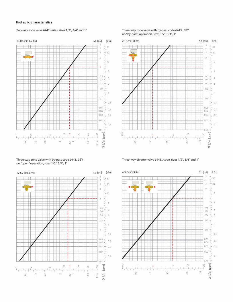
Hydraulic characteristics
Two-way zone valve 6442 series, sizes 1/2”, 3/4” and 1” Three-way zone valve with by-pass code 6443.. 3BYon “by-pass” operation, sizes 1/2”, 3/4”, 1”
2.1 Cv (1.8 Kv) ∆p (psi) (kPa)
.10
.25
102 5 20
1.10.60
0.1
1
0.2
0.3
0.5
2
3
5
1
10
2
3
5
20
30
0.4
4
0.01
0.02
0.03
0.05
0,1
0,2
0,3
0,5
0.04
Three-way diverter valve 6443.. code, sizes 1/2”, 3/4” and 1”
4.5 Cv (3.9 Kv) ∆p (psi) (kPa)
0.1
1
0.2
0.3
0.5
2
3
5
1
10
2
3
5
20
30
0.4
4
0.01
0.02
0.03
0.05
0,1
0,2
0,3
0,5
0.04
13.0 Cv (11.2 Kv)
G (l
/s)
(gpm
)
∆p (psi) (kPa)
.15
.25
102 5 20
1.5
.10
2.2
3.15
501
0.1
1
0.2
0.3
0.5
2
3
5
1
10
2
3
5
20
30
0.4
4
0.01
0.02
0.03
0.05
0,1
0,2
0,3
0,5
0.04
12 Cv (10.3 Kv) ∆p (psi) (kPa)
0.1
1
0.2
0.3
0.5
2
3
5
1
10
2
3
5
20
30
0.4
4
0.01
0.02
0.03
0.05
0,1
0,2
0,3
0,5
0.04
Three-way zone valve with by-pass code 6443.. 3BYon “open” operation, sizes 1/2”, 3/4”, 1”
G (l
/s)
(gpm
)
10.5
.05
CALEFFI
CALEFFI
A B
AB
A B
AB
13
.10
.25
102 5 20
1.10.60
G (l
/s)
(gpm
)
10.5
.05
35
.82
G (l
/s)
(gpm
)
.15
.25
102 5 20
1.5
.10
2.2
3.15
501 13 35
.82
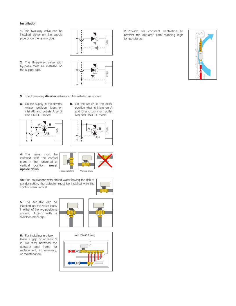
4b. For installations with chilled water having the risk of condensation, the actuator must be installed with the control stem vertical.
5. The actuator can be installed on the valve body in either of the two positions shown. Attach with a stainless steel clip.
6. For installing in a box leave a gap of at least 2 in (50 mm) between the actuator and frame for replacement, if necessary, or maintenance.
Installation
1. The two-way valve can be installed either on the supply pipe or on the return pipe.
LOA
DLO
AD
LOA
DLO
AD
2. The three-way valve with by-pass must be installed on the supply pipe.
LOA
DLO
AD
LOA
DLO
AD
a. On the supply in the diverter /mixer position (common inlet AB and outlets A or B) and ON/OFF mode
b. On the return in the mixer position (that is inlets on A and B and common outlet AB) and ON/OFF mode
3. The three-way diverter valves can be installed as shown:
4. The valve must be installed with the control stem in the horizontal or vertical position, never upside down.
LOA
DLO
AD
LOA
DLO
AD
LOA
DLO
AD
LOA
DLO
AD
A
AB
BA
AB
B
Vertical stemHorizontal stem
A B
AB
A B
AB
A B
AB
A B
AB
CA
LE
FF
IC
AL
EF
FI
CA
LE
FF
I
CA
LE
FF
IC
AL
EF
FI
CA
LE
FF
IC
AL
EF
FI
CA
LE
FF
I
CA
LEFFI
35
6
min. 30 mm
min. 2 in (50 mm)
CALEFFI
7. Provide for constant ventilation to prevent the actuator from reaching high temperatures.
C
ALEFFI
C
ALEFFI
C
ALEFFI
C
ALEFFI
Max0,8 AM
OPEN
CLOSE
LN

Wiring diagrams
1. Connection diagram for room SPDT thermostat (RT) and electric supply.
The illustrated connection permits opening and closing the valve according to the ambient thermostat signal.
2. Connection diagram for single contact thermostat (RT) or on-off switching device. If the termostat has only a single contact, or on-off switch is used,
install a SPDT relay as shown below.
MCL
OSE
OPE
N
RTN
L
Max 5 A
ACTUATOR
M
CLO
SE
OPE
N
RTN
L
Max 5 A
ACTUATOR
M
CLO
SE
OPE
N
RTN
L
Max 5 A
ACTUATOR
M
CLO
SE
OPE
N
RTN
L
Max 5 A
ACTUATOR
Micro-switches
The motor is equipped with limit micro-switches that shut off the motor when reaching the valve open/closed positions.
The micro-switch activates at approximately 80% valve opening.
3. Pump disconnection diagram when no zone is in operation. This diagram, using the micro-switch, turns off the pump when the
zone valve is closed. If the pump has an input current greater than 5 A (24 V), use an intermediate relay.
M
CLO
SE
OPE
N
24 VACRelay
N
L
Max 5 A
ACTUATOR
RT
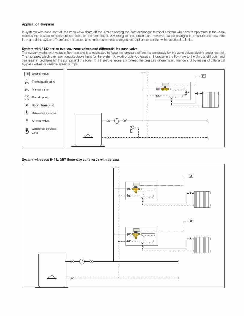
Shut-off valve
Thermostatic valve
Manual valve
Electric pump
Room thermostat
Differential by-pass
Air vent valve
Differential by-passvalve
RT
RT
RT
RT
CALEFFI
CALEFFI
CALEFFI
System with 6442 series two-way zone valves and differential by-pass valveThe system works with variable flow rate and it is necessary to keep the pressure differential generated by the zone valves closing under control. This increase, which can reach unacceptable limits for the system to work properly, creates an increase in the flow rate to the circuits still open and can result in problems for the pumps and the boiler. It is therefore necessary to keep the pressure differentials under control by means of differential by-pass valves or variable speed pumps.
Application diagrams
In systems with zone control, the zone valve shuts off the circuits serving the heat exchanger terminal emitters when the temperature in the room reaches the desired temperature set point on the thermostat. Switching off this circuit can, however, cause changes in pressure and flow rate throughout the system. Therefore, it is essential to make sure these changes are kept under control within acceptable limits.
System with code 6443.. 3BY three-way zone valve with by-pass
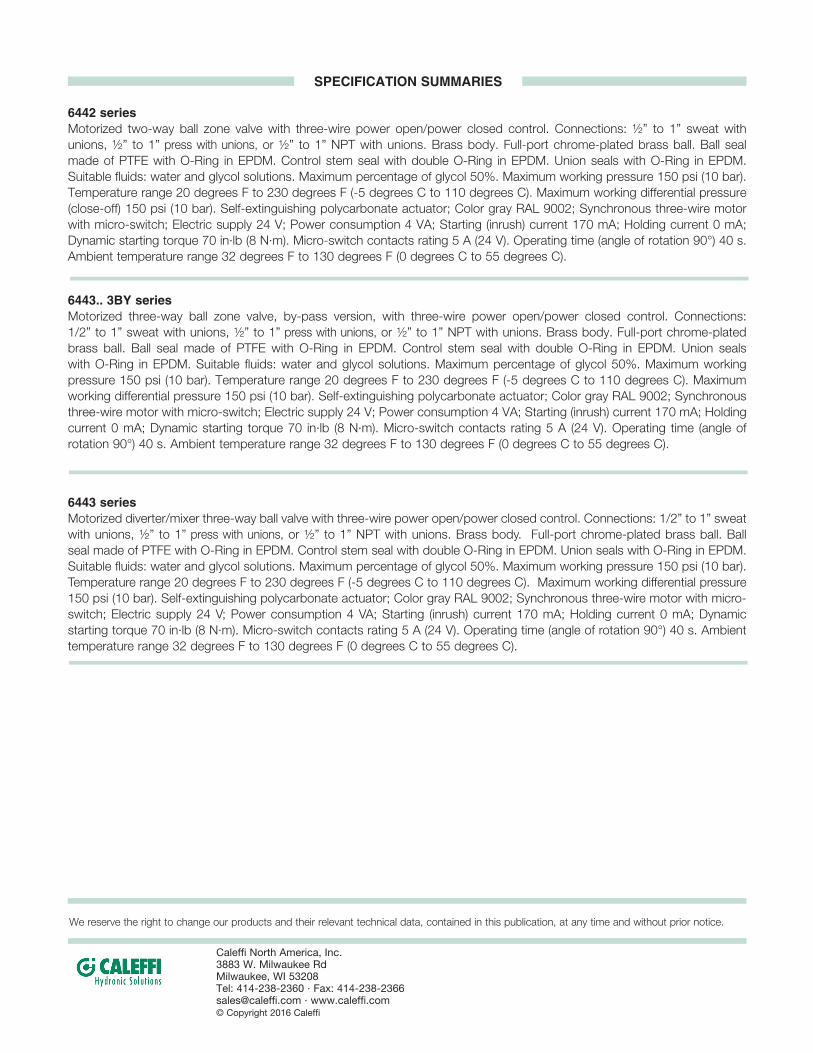
6442 seriesMotorized two-way ball zone valve with three-wire power open/power closed control. Connections: ½” to 1” sweat with unions, ½” to 1” press with unions, or ½” to 1” NPT with unions. Brass body. Full-port chrome-plated brass ball. Ball seal made of PTFE with O-Ring in EPDM. Control stem seal with double O-Ring in EPDM. Union seals with O-Ring in EPDM. Suitable fluids: water and glycol solutions. Maximum percentage of glycol 50%. Maximum working pressure 150 psi (10 bar). Temperature range 20 degrees F to 230 degrees F (-5 degrees C to 110 degrees C). Maximum working differential pressure (close-off) 150 psi (10 bar). Self-extinguishing polycarbonate actuator; Color gray RAL 9002; Synchronous three-wire motor with micro-switch; Electric supply 24 V; Power consumption 4 VA; Starting (inrush) current 170 mA; Holding current 0 mA; Dynamic starting torque 70 in·lb (8 N·m). Micro-switch contacts rating 5 A (24 V). Operating time (angle of rotation 90°) 40 s. Ambient temperature range 32 degrees F to 130 degrees F (0 degrees C to 55 degrees C).
6443.. 3BY seriesMotorized three-way ball zone valve, by-pass version, with three-wire power open/power closed control. Connections: 1/2” to 1” sweat with unions, ½” to 1” press with unions, or ½” to 1” NPT with unions. Brass body. Full-port chrome-plated brass ball. Ball seal made of PTFE with O-Ring in EPDM. Control stem seal with double O-Ring in EPDM. Union seals with O-Ring in EPDM. Suitable fluids: water and glycol solutions. Maximum percentage of glycol 50%. Maximum working pressure 150 psi (10 bar). Temperature range 20 degrees F to 230 degrees F (-5 degrees C to 110 degrees C). Maximum working differential pressure 150 psi (10 bar). Self-extinguishing polycarbonate actuator; Color gray RAL 9002; Synchronousthree-wire motor with micro-switch; Electric supply 24 V; Power consumption 4 VA; Starting (inrush) current 170 mA; Holding current 0 mA; Dynamic starting torque 70 in·lb (8 N·m). Micro-switch contacts rating 5 A (24 V). Operating time (angle of rotation 90°) 40 s. Ambient temperature range 32 degrees F to 130 degrees F (0 degrees C to 55 degrees C).
6443 seriesMotorized diverter/mixer three-way ball valve with three-wire power open/power closed control. Connections: 1/2” to 1” sweat with unions, ½” to 1” press with unions, or ½” to 1” NPT with unions. Brass body. Full-port chrome-plated brass ball. Ball seal made of PTFE with O-Ring in EPDM. Control stem seal with double O-Ring in EPDM. Union seals with O-Ring in EPDM. Suitable fluids: water and glycol solutions. Maximum percentage of glycol 50%. Maximum working pressure 150 psi (10 bar). Temperature range 20 degrees F to 230 degrees F (-5 degrees C to 110 degrees C). Maximum working differential pressure 150 psi (10 bar). Self-extinguishing polycarbonate actuator; Color gray RAL 9002; Synchronous three-wire motor with micro-switch; Electric supply 24 V; Power consumption 4 VA; Starting (inrush) current 170 mA; Holding current 0 mA; Dynamic starting torque 70 in·lb (8 N·m). Micro-switch contacts rating 5 A (24 V). Operating time (angle of rotation 90°) 40 s. Ambient temperature range 32 degrees F to 130 degrees F (0 degrees C to 55 degrees C).
SPECIFICATION SUMMARIES
We reserve the right to change our products and their relevant technical data, contained in this publication, at any time and without prior notice.
Caleffi North America, Inc. 3883 W. Milwaukee RdMilwaukee, WI 53208Tel: 414-238-2360 · Fax: [email protected] · www.caleffi.com © Copyright 2016 Caleffi