Embed Size (px)
Citation preview

0Motorpact™
MV distributionfactory built assembliesat your service
0IEC instructions for use
FVNR, RVAT, RVSS, and INC cable cubicles
English

0
0contents
general information . . . . . . . . . . . . . . . . . . . . . . . . . . . . . . . . . . 7marking . . . . . . . . . . . . . . . . . . . . . . . . . . . . . . . . . . . . . . . . . . 7standard tightening torques . . . . . . . . . . . . . . . . . . . . . . . . . . . 7
non-greased screws and bolts . . . . . . . . . . . . . . . . . . . . . . 7application methods . . . . . . . . . . . . . . . . . . . . . . . . . . . . . . 7
general description . . . . . . . . . . . . . . . . . . . . . . . . . . . . . . . . . . 9full voltage non-reversing controller (FVNR) cubicle . . . . . . . . 9FVNR cubicle with Merlin Gerin Propivar power factor correction capacitors (PFCC) . . . . . . . . . . . . . . . . . . . . . . . . 10reduced voltage soft start (RVSS) cubicle . . . . . . . . . . . . . . . 11reduced voltage autotransformer (RVAT) cubicle . . . . . . . . . 12incoming cable cubicle . . . . . . . . . . . . . . . . . . . . . . . . . . . . . 13identification (FVNR) . . . . . . . . . . . . . . . . . . . . . . . . . . . . . . . 14
FVNR . . . . . . . . . . . . . . . . . . . . . . . . . . . . . . . . . . . . . . 14contactor . . . . . . . . . . . . . . . . . . . . . . . . . . . . . . . . . . . 14
front operator panel description . . . . . . . . . . . . . . . . . . . . . . . 15procedure pictogram . . . . . . . . . . . . . . . . . . . . . . . . . . . . . . . 15
steps for closing of circuit . . . . . . . . . . . . . . . . . . . . . . 15
instructions for access to the inside of the cubicle . . . . . . . 17accessing the MV compartment (cables, busbars, CT, cable earthing switch, surge arresters, fuses, contactor, transformers) . . . . . . . . . . . . . . . . . . . . . . . . . . . . . . . . . . . . . 17
safety rules . . . . . . . . . . . . . . . . . . . . . . . . . . . . . . . . . . . . 17access to LV cabinet (instrument components, relays, and communication modules) . . . . . . . . . . . . . . . . . . . . . . . . . . . . 17accessing the medium voltage compartment FVNR . . . . . . . 18
opening the medium voltage compartment door . . . . . . . 18accessing the cable compartment FVNR . . . . . . . . . . . . . 18
steps to access the cable compartment of an FVNRcubicle . . . . . . . . . . . . . . . . . . . . . . . . . . . . . . . . . . . . . 18
accessing the busbar compartment FVNR . . . . . . . . . . . . . . . . . 19steps to access the busbar compartment from the rear of the cubicle . . . . . . . . . . . . . . . . . . . . . . . . . . . . . . . . . . . . 19steps to access the busbar compartment from the front of the cubicle . . . . . . . . . . . . . . . . . . . . . . . . . . . . . . . . . . . . . . 19
accessing the medium voltage compartments RVAT or RVSS20steps to OPEN the RVAT or RVSS MV doors . . . . . . . . . 20steps to CLOSE the RVAT or RVSS MV doors. . . . . . . . . 20
accessing the busbar compartments RVAT or RVSS . . . . . . 21steps to access the busbar compartment from the front of the cubicle . . . . . . . . . . . . . . . . . . . . . . . . . . . . . . . . . . . 21
installation and operation recommendation . . . . . . . . . . . . . 23switchgear aging resistance . . . . . . . . . . . . . . . . . . . . . . . . . 23operation . . . . . . . . . . . . . . . . . . . . . . . . . . . . . . . . . . . . . . . . 23steps for tests . . . . . . . . . . . . . . . . . . . . . . . . . . . . . . . . . . . . 24
safety rules . . . . . . . . . . . . . . . . . . . . . . . . . . . . . . . . . . . . 24preliminary operation check . . . . . . . . . . . . . . . . . . . . . . . 24
voltage presence on MV cables . . . . . . . . . . . . . . . . . . . . . . 25cubicle equipped with VPIS voltage indicator boxes . . . . 25instructions for use . . . . . . . . . . . . . . . . . . . . . . . . . . . . . . 25
MV cable test . . . . . . . . . . . . . . . . . . . . . . . . . . . . . . . . . . . . . 25steps to test conditions . . . . . . . . . . . . . . . . . . . . . . . . . . . 25voltage injections on MV outgoing cable heads . . . . . . . . 25
replacing the voltage indicator box . . . . . . . . . . . . . . . . . . . . 26steps for removing . . . . . . . . . . . . . . . . . . . . . . . . . . . . . . 26steps for placing . . . . . . . . . . . . . . . . . . . . . . . . . . . . . . . . 26
46032-700-09C.fm/3
0contents
operating instructions . . . . . . . . . . . . . . . . . . . . . . . . . . . . . . . 28disconnector operation . . . . . . . . . . . . . . . . . . . . . . . . . . . . . 28
interlock shuttle . . . . . . . . . . . . . . . . . . . . . . . . . . . . . . 28description . . . . . . . . . . . . . . . . . . . . . . . . . . . . . . . . . . . . 28
opening the disconnector . . . . . . . . . . . . . . . . . . . . . . . . . . . . 29closing the disconnector . . . . . . . . . . . . . . . . . . . . . . . . . . . . 30operating the contactor . . . . . . . . . . . . . . . . . . . . . . . . . . . . . 31
description . . . . . . . . . . . . . . . . . . . . . . . . . . . . . . . . . . . . 31steps to CLOSE . . . . . . . . . . . . . . . . . . . . . . . . . . . . . . . . 31steps to OPEN . . . . . . . . . . . . . . . . . . . . . . . . . . . . . . . . . 31
removing or installing the contactor . . . . . . . . . . . . . . . . . . . . 32starting status . . . . . . . . . . . . . . . . . . . . . . . . . . . . . . . . . . 32steps to remove the contactor . . . . . . . . . . . . . . . . . . . . . 32steps to install the contactor . . . . . . . . . . . . . . . . . . . . . . . 33
back light assembly (optional) . . . . . . . . . . . . . . . . . . . . . . . . 34battery replacement . . . . . . . . . . . . . . . . . . . . . . . . . . . . . 34
steps for removal . . . . . . . . . . . . . . . . . . . . . . . . . . . . . 34steps to place back into operation . . . . . . . . . . . . . . . . 34
cable earthing switch operation (optional) . . . . . . . . . . . . . . . 35description . . . . . . . . . . . . . . . . . . . . . . . . . . . . . . . . . . . . 35instructions for use . . . . . . . . . . . . . . . . . . . . . . . . . . . . . . 35cable earthing switch operating condition . . . . . . . . . . . . . 35
interlock shuttle . . . . . . . . . . . . . . . . . . . . . . . . . . . . . . 35closing the cable earthing switch . . . . . . . . . . . . . . . . . . . . . . 36opening the cable earthing switch . . . . . . . . . . . . . . . . . . . . . 36removing and installing fuses . . . . . . . . . . . . . . . . . . . . . . . . 37
steps to remove fuses . . . . . . . . . . . . . . . . . . . . . . . . . . . 37fuse characteristics . . . . . . . . . . . . . . . . . . . . . . . . . . . 38
steps to install fuses . . . . . . . . . . . . . . . . . . . . . . . . . . . . . 38fuse tool (optional) . . . . . . . . . . . . . . . . . . . . . . . . . . . . . . . . . 39
steps to install rear and middle fuses . . . . . . . . . . . . . . . . 39steps to install front fuses . . . . . . . . . . . . . . . . . . . . . . . . . . . .42steps to remove fuses . . . . . . . . . . . . . . . . . . . . . . . . . . . 44
blown fuse indicator . . . . . . . . . . . . . . . . . . . . . . . . . . . . . . . . 45removing and installing VT primary fuses . . . . . . . . . . . . . . . 46
steps to replace fuses . . . . . . . . . . . . . . . . . . . . . . . . . . . . 46steps to disassemble the fuse tube . . . . . . . . . . . . . . . . . 46steps to assemble the fuse tube . . . . . . . . . . . . . . . . . . . . 46steps to place back into operation . . . . . . . . . . . . . . . . . . 46
removing and installing fuses of the Merlin Gerin Propivar power factor correction capacitors (PFCC) inside Motorpact enclosures . . . . . . . . . . . . . . . . . . . . . . . . . . . . . . . . . . . . . . . 47
steps to remove fuses . . . . . . . . . . . . . . . . . . . . . . . . . . . . 47steps to install fuses . . . . . . . . . . . . . . . . . . . . . . . . . . . . . 47
locking using padlocks . . . . . . . . . . . . . . . . . . . . . . . . . . . . . . 48number of possible padlocks per cubicle type . . . . . . . . . 48padlocking the disconnector . . . . . . . . . . . . . . . . . . . . . . . 48padlocking the cable earthing switch. . . . . . . . . . . . . . . . . 49padlocking the incoming cable cubicle doors . . . . . . . . . . 49
locking using keylocks (optional) . . . . . . . . . . . . . . . . . . . . . . 50number of possible locks per cubicle type . . . . . . . . . . . . 50
keylocking the disconnector . . . . . . . . . . . . . . . . . . . . . . . . . . 50locking the disconnector open or closed with 1 keylock . . 50locking the disconnector open or closed with 2 keylocks . 50locking the cable earthing switch open or closed . . . . . . . 51
46032-700-09C.fm/4
0contents
RVAT (reduced voltage autotransformer) . . . . . . . . . . . . . . . 52description . . . . . . . . . . . . . . . . . . . . . . . . . . . . . . . . . . . . 52limited duty cycle rating . . . . . . . . . . . . . . . . . . . . . . . . . . 53
keylocks on an RVAT . . . . . . . . . . . . . . . . . . . . . . . . . . . . . . 53keylocking with disconnector (without cable earthing switch) 53keylocking (with cable earthing switch) . . . . . . . . . . . . . . 53
RVAT operation . . . . . . . . . . . . . . . . . . . . . . . . . . . . . . . . . . . 54autotransformers . . . . . . . . . . . . . . . . . . . . . . . . . . . . . . . 54relay setting . . . . . . . . . . . . . . . . . . . . . . . . . . . . . . . . . . . 54tap setting . . . . . . . . . . . . . . . . . . . . . . . . . . . . . . . . . . . . . 54
steps to change tap settings . . . . . . . . . . . . . . . . . . . . 54steps to CLOSE . . . . . . . . . . . . . . . . . . . . . . . . . . . . . . . . 55steps to OPEN . . . . . . . . . . . . . . . . . . . . . . . . . . . . . . . . . 55
RVSS (reduced voltage soft start) . . . . . . . . . . . . . . . . . . . . . 56description . . . . . . . . . . . . . . . . . . . . . . . . . . . . . . . . . . . . 56
keylocks on an RVSS . . . . . . . . . . . . . . . . . . . . . . . . . . . . . . 57keylocking with disconnector (without cable earthing switch) 57keylocking (with cable earthing switch) . . . . . . . . . . . . . . 57
removing a contactor from an RVAT or RVSS cubicle . . . . . 58preliminary steps . . . . . . . . . . . . . . . . . . . . . . . . . . . . . . . 58
steps to remove a start, run, or bypass contactor . . . . . . . . . 58installing a contactor in an RVAT or RVSS cubicle . . . . . . . . 59
preliminary steps . . . . . . . . . . . . . . . . . . . . . . . . . . . . . . . 59steps to install a start, run, or bypass contactor . . . . . . . . . . 59using a lift truck (optional) . . . . . . . . . . . . . . . . . . . . . . . . . . . 60MDT107 thermal diagnostic system (optional) . . . . . . . . . . . 61
description . . . . . . . . . . . . . . . . . . . . . . . . . . . . . . . . . . . . 61functions . . . . . . . . . . . . . . . . . . . . . . . . . . . . . . . . . . . . . . 62
monitoring of temperature buildup in 2 zones . . . . . . . 62triggering of a pre-alarm . . . . . . . . . . . . . . . . . . . . . . . 62triggering of an alarm . . . . . . . . . . . . . . . . . . . . . . . . . 62self-monitoring of the module . . . . . . . . . . . . . . . . . . . 63self-monitoring of sensors . . . . . . . . . . . . . . . . . . . . . . 63
wiring . . . . . . . . . . . . . . . . . . . . . . . . . . . . . . . . . . . . . . . . . . . 64wiring and operation for MDT107 . . . . . . . . . . . . . . . . . . . 64ratings . . . . . . . . . . . . . . . . . . . . . . . . . . . . . . . . . . . . . . . . 64
MDT107 module location . . . . . . . . . . . . . . . . . . . . . . . . . . . . 65MDT107 sensors location . . . . . . . . . . . . . . . . . . . . . . . . . . . 66
setting the temperature rise thresholds . . . . . . . . . . . . . . 66setting the ambient temperature correction . . . . . . . . . . . 67
steps to set the ambient temperature . . . . . . . . . . . . . 67troubleshooting . . . . . . . . . . . . . . . . . . . . . . . . . . . . . . . . . 68
maintenance . . . . . . . . . . . . . . . . . . . . . . . . . . . . . . . . . . . . . . . 69maintenance . . . . . . . . . . . . . . . . . . . . . . . . . . . . . . . . . . . . . 69
preventative maintenance . . . . . . . . . . . . . . . . . . . . . . . . 69environmental conditions . . . . . . . . . . . . . . . . . . . . . . . . . 69
ideal conditions . . . . . . . . . . . . . . . . . . . . . . . . . . . . . . 69standard conditions . . . . . . . . . . . . . . . . . . . . . . . . . . . 70aggressive conditions . . . . . . . . . . . . . . . . . . . . . . . . . 70
inspecting the equipment . . . . . . . . . . . . . . . . . . . . . . . . . . . . 71
replacement parts . . . . . . . . . . . . . . . . . . . . . . . . . . . . . . . . . . 73replacement parts . . . . . . . . . . . . . . . . . . . . . . . . . . . . . . . . . 73
troubleshooting . . . . . . . . . . . . . . . . . . . . . . . . . . . . . . . . . . . . 75troubleshooting . . . . . . . . . . . . . . . . . . . . . . . . . . . . . . . . . . . 75
glossary . . . . . . . . . . . . . . . . . . . . . . . . . . . . . . . . . . . . . . . . . . 77
46032-700-09C.fm/5

0
46032-700-09C.fm/6
0general information
standard tightening torques
non-greased screws and bolts
application methods The conical washers placed on the external sides of the busbars ensure better distribution of stress regarding bolts tightened to the recommended torques.
marking It is strictly forbidden to walk on the parts bearing this marking.
It is strictly forbidden to remove the parts bearing this marking when the equipment is energized.
screwbusbar torque in N•m
mech. torque in N•m
Ø 6 — 10
Ø 8 28 20
Ø 10 50 35
Ø 12 75 55
Ø 14 — 120
46032-700-09C.fm/7

0
46032-700-09C.fm/8
0general description
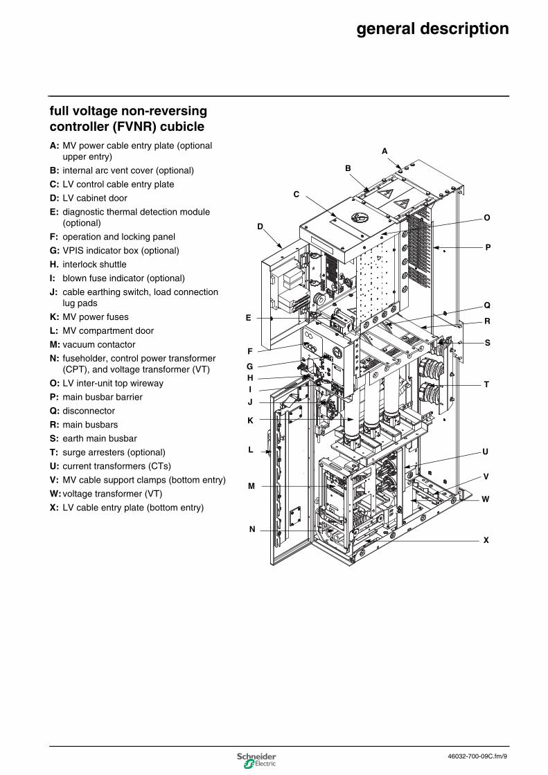
full voltage non-reversing controller (FVNR) cubicleA: MV power cable entry plate (optional
upper entry)
B: internal arc vent cover (optional)
C: LV control cable entry plate
D: LV cabinet door
E: diagnostic thermal detection module (optional)
F: operation and locking panel
G: VPIS indicator box (optional)
H. interlock shuttle
I: blown fuse indicator (optional)
J: cable earthing switch, load connection lug pads
K: MV power fuses
L: MV compartment door
M: vacuum contactor
N: fuseholder, control power transformer (CPT), and voltage transformer (VT)
O: LV inter-unit top wireway
P: main busbar barrier
Q: disconnector
R: main busbars
S: earth main busbar
T: surge arresters (optional)
U: current transformers (CTs)
V: MV cable support clamps (bottom entry)
W:voltage transformer (VT)
X: LV cable entry plate (bottom entry)
B
C
D
E
F
G
J
K
L
M
O
P
R
T
S
U
A
V
W
NX
I
Q
H
46032-700-09C.fm/9
0general description
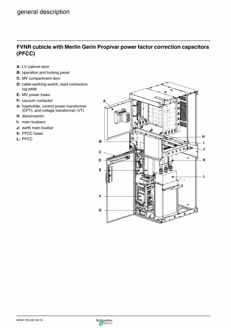
FVNR cubicle with Merlin Gerin Propivar power factor correction capacitors (PFCC)
A: LV cabinet door
B: operation and locking panel
C: MV compartment door
D: cable earthing switch, load connection lug pads
E: MV power fuses
F: vacuum contactorG: fuseholder, control power transformer
(CPT), and voltage transformer (VT)
H. disconnector
I: main busbars
J: earth main busbarK: PFCC fuses
L: PFCC
A
B
D
F
E
C
G
H
I
J
K
L
46032-700-09C.fm/10
0general description
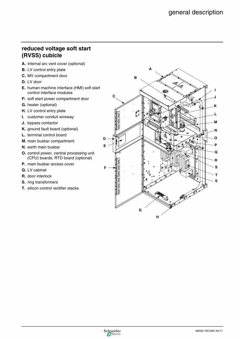
reduced voltage soft start (RVSS) cubicleA. internal arc vent cover (optional)
B. LV control entry plate
C. MV compartment door
D. LV door
E. human machine interface (HMI) soft start control interface modules
F: soft start power compartment door
G. heater (optional)
H. LV control entry plate
I. customer conduit wireway
J. bypass contactor
K. ground fault board (optional)
L. terminal control board
M. main busbar compartment
N. earth main busbar
O. control power, central processing unit (CPU) boards, RTD board (optional)
P. main busbar access cover
Q. LV cabinet
R. door interlock
S. ring transformers
T. silicon control rectifier stacks
A
B
C
D
E
F
G
I
J
K
L
M
N
O
P
Q
R
S
T
S
H
46032-700-09C.fm/11
0general description
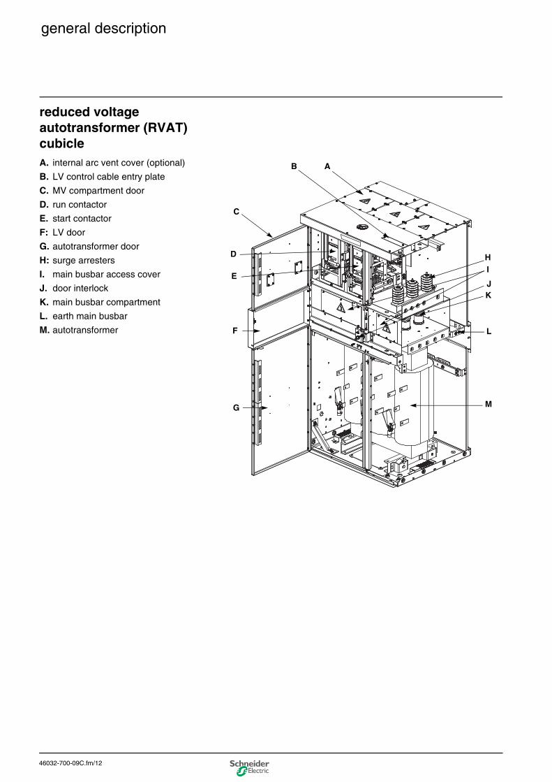
reduced voltage autotransformer (RVAT) cubicleA. internal arc vent cover (optional)
B. LV control cable entry plate
C. MV compartment door
D. run contactor
E. start contactor
F: LV door
G. autotransformer door
H: surge arresters
I. main busbar access cover
J. door interlock
K. main busbar compartment
L. earth main busbar
M. autotransformer
AB
C
D
E
F
G
J
I
K
L
M
H
46032-700-09C.fm/12
0general description
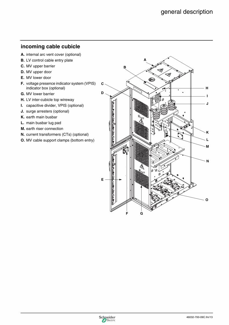
incoming cable cubicleA. internal arc vent cover (optional)
B. LV control cable entry plate
C. MV upper barrier
D. MV upper door
E. MV lower door
F. voltage presence indicator system (VPIS) indicator box (optional)
G. MV lower barrier
H. LV inter-cubicle top wireway
I. capacitive divider, VPIS (optional)
J. surge arresters (optional)
K. earth main busbar
L. main busbar lug pad
M. earth riser connection
N. current transformers (CTs) (optional)
O. MV cable support clamps (bottom entry)
A
B
C
D
E
O
H
I
J
K
L
M
N
F G
46032-700-09C.fm/13
0general description
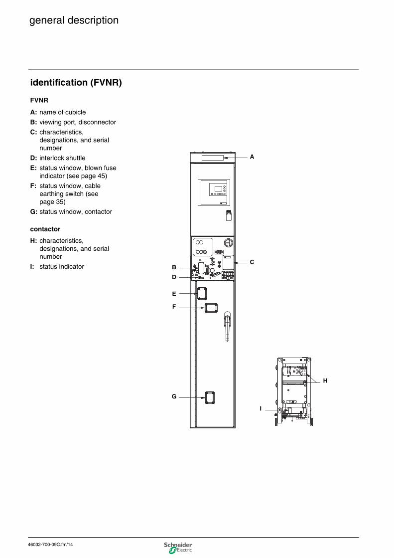
identification (FVNR)
FVNR
A: name of cubicle
B: viewing port, disconnector
C: characteristics, designations, and serial number
D: interlock shuttle
E: status window, blown fuse indicator (see page 45)
F: status window, cable earthing switch (see page 35)
G: status window, contactor
contactor
H: characteristics, designations, and serial number
I: status indicator
A
BC
H
E
G
I
D
F
46032-700-09C.fm/14

0general description
front operator panel description
A: contactor control panel
B: voltage presence indicator system (VPIS)
C: pushbutton for back light (optional)
D: disconnector viewing port
E: disconnector status indicator
F: location for cable earthing switch operation padlock
G: disconnector operating access port
H: cable earthing switch operating access port
I: location for disconnector operation padlock
J: procedure pictogram
K: interlock shuttle
procedure pictogramsteps for closing of circuit
1. MV compartment door position, close and latch
2. If the cable earthing switch is not supplied, skip to step 5. If the cable earthing switch is supplied, move the cable earthing switch access port from the locked to unlocked position. This requires the interlock shuttle to be in the right-hand position. see “cable earthing switch operation (optional)”
3. OPEN or un-earth the cable earthing switch
4. Move the cable earthing switch access port from the unlocked to locked position; then move the interlock shuttle from the right-hand to left-hand position. “disconnector operation”
5. Move the disconnector access port from the locked to unlocked position
6. CLOSE the disconnector
7. Move the disconnector access port from the unlocked to locked position
8. CLOSE the contactor
A
B
C
D
EFH
I
G
J
K
46032-700-09C.fm/15

0
46032-700-09C.fm/16

0instructions for access to theinside of the cubicle
accessing the MV compartment (cables, busbars, CT, cable earthing switch, surge arresters, fuses, contactor, transformers)
safety rules see “accessing the medium voltage compartment FVNR” and “accessing the medium voltage compartments RVAT or RVSS”
cables see "cable connections" in the installation instruction guide
busbars see "installing busbars" in the installation instruction guide
CT (current transformer) see “general description” for the mounting locations
cable earthing switch see “cable earthing switch operation (optional)”
surge arresters see “general description” for the mounting locations.
fuses see “removing and installing fuses”
contactor see “removing or installing the contactor”
transformers see “general description” for the mounting locations
access to LV cabinet (instrument components, relays, and communication modules)
see "accessing the low voltage compartment" in the installation instruction guide
All operations described hereafter must be carried out in compliance with the safety standards in force, under the responsibility of a competent person.
All operations described hereafter must be carried out in compliance with the safety standards in force, under the responsibility of a competent person.
46032-700-09C.fm/17

0instructions for access to theinside of the cubicle
accessing the medium voltage compartment FVNRMotorpact™ Motor Controllers are shipped with the disconnector in the earthed/OPEN position.
The disconnector must be in the earthed/OPEN position to open the medium voltage compartment door.
see “disconnector operation”
The cable earthing switch (optional) must be in the earthed/CLOSED position to open the medium voltage compartment door.
see “cable earthing switch operation (optional)”
opening the medium voltage compartment door
accessing the cable compartment FVNR
Always look through the viewing window to verify the actual position of the disconnector switch blades before trying to open the MV compartment door.
door closed, rotate handle 90° door openhandle rotated
All operations described hereafter must be carried out in compliance with the safety standards in force, under the responsibility of a competent person.
Always remove all power from the cubicle and use a properly rated testing device to confirm there is no voltage present.
Always look through the rear viewing window to verify that the MV compartment door is OPEN, before removing the MV cable compartment cover.
MV compartment door viewing window
MV compartment door (opened 90°)
steps to access the cable compartment of an FVNR cubicle
■ Verify through the rear viewing window that the MV compartment door is OPEN, the power has been removed from the cubicle, and the load connections have been properly earthed.
■ Remove the lower MV cable compartment cover. 4 M10x20 screws.
tightening torque: 35 N•m
After installation or maintenance, ensure all covers are replaced using the original hardware.
rear view
46032-700-09C.fm/18
0instructions for access to theinside of the cubicle
46032-700-09C.fm/19
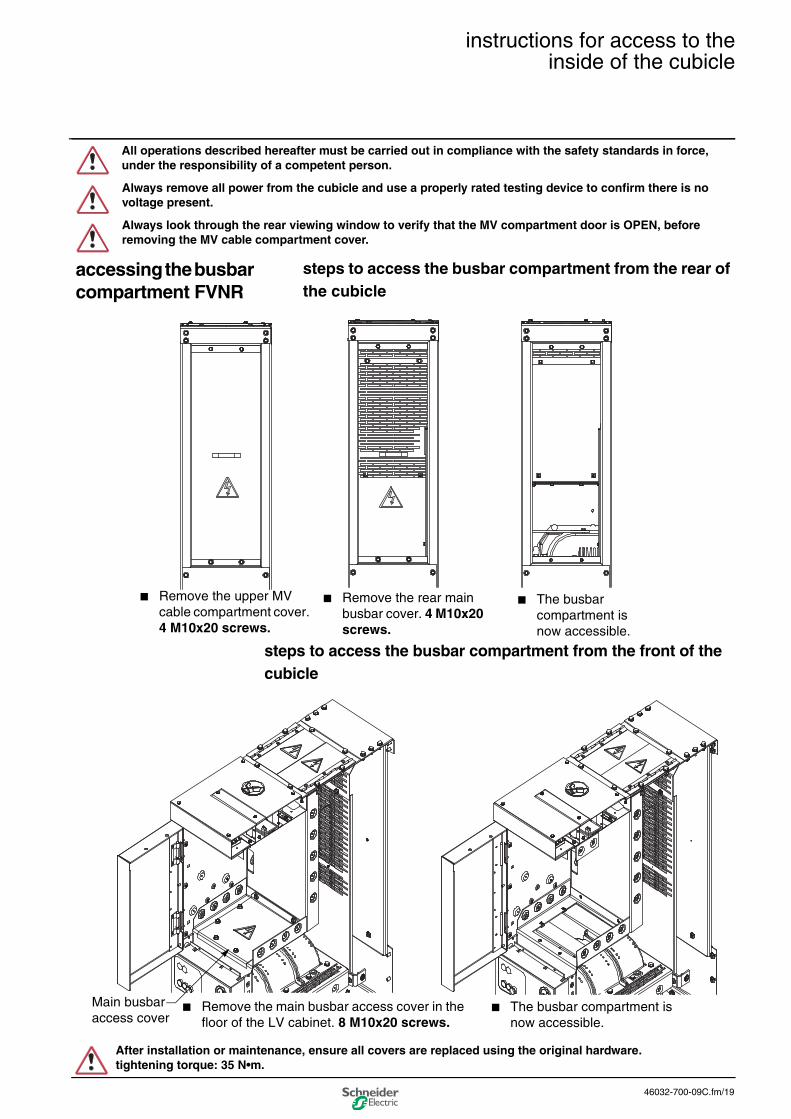
accessing the busbar compartment FVNR
steps to access the busbar compartment from the rear of the cubicle
steps to access the busbar compartment from the front of the cubicle
All operations described hereafter must be carried out in compliance with the safety standards in force, under the responsibility of a competent person.
Always remove all power from the cubicle and use a properly rated testing device to confirm there is no voltage present.
Always look through the rear viewing window to verify that the MV compartment door is OPEN, before removing the MV cable compartment cover.
■ Remove the upper MV cable compartment cover. 4 M10x20 screws.
■ Remove the rear main busbar cover. 4 M10x20 screws.
■ The busbar compartment is now accessible.
■ Remove the main busbar access cover in the floor of the LV cabinet. 8 M10x20 screws.
■ The busbar compartment is now accessible.
Main busbar access cover
After installation or maintenance, ensure all covers are replaced using the original hardware. tightening torque: 35 N•m.
0instructions for access to theinside of the cubicle
accessing the medium voltage compartments RVAT or RVSS
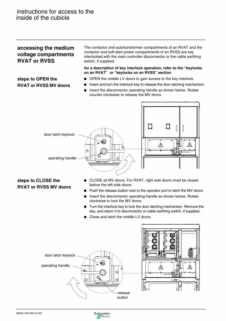
The contactor and autotransformer compartments of an RVAT and the contactor and soft start power compartments of an RVSS are key interlocked with the main controller disconnector or the cable earthing switch, if supplied.
for a description of key interlock operation, refer to the “keylocks on an RVAT” or “keylocks on an RVSS” section
steps to OPEN the RVAT or RVSS MV doors
■ OPEN the middle LV doors to gain access to the key interlock.
■ Insert and turn the interlock key to release the door latching mechanism.
■ Insert the disconnector operating handle as shown below. Rotate counter-clockwise to release the MV doors.
steps to CLOSE the RVAT or RVSS MV doors
■ CLOSE all MV doors. For RVAT, right side doors must be closed before the left side doors.
■ Push the release button next to the operator port to latch the MV doors.
■ Insert the disconnector operating handle as shown below. Rotate clockwise to lock the MV doors.
■ Turn the interlock key to lock the door latching mechanism. Remove the key, and return it to disconnector or cable earthing switch, if supplied.
■ Close and latch the middle LV doors.
door latch keylock
operating handle
door latch keylock
operating handle
release button
46032-700-09C.fm/20
0instructions for access to theinside of the cubicle
accessing the busbar compartments RVAT or RVSS
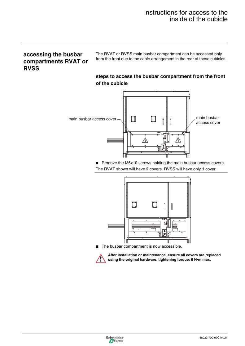
The RVAT or RVSS main busbar compartment can be accessed only from the front due to the cable arrangement in the rear of these cubicles.
steps to access the busbar compartment from the front of the cubicle
■ Remove the M6x10 screws holding the main busbar access covers.
The RVAT shown will have 2 covers. RVSS will have only 1 cover.
main busbar access cover main busbar access cover
■ The busbar compartment is now accessible.
After installation or maintenance, ensure all covers are replaced using the original hardware. tightening torque: 6 N•m max.
46032-700-09C.fm/21

0
46032-700-09C.fm/22
0installation and operationrecommendation
switchgear aging resistance
The switchgear’s resistance to aging depends upon 3 factors.
■ The necessity of correct implementation of connections:
New cold-shrink or slip-on technology offers ease of installation.
■ The effect of the relative humidity factor:
Heating resistor installation is essential in climates with a high rate of relative humidity and with significant temperature differentials.
■ Ventilation control:
Provide area ventilation, heating, and air conditioning to maintain the ambient temperature around the equipment between - 5 °C and 40 °C.
operation It is strongly advised to periodically carry out (minimum every 2 years) a few operation cycles on operating devices.
Outside normal conditions of use (between - 5 °C and 40 °C, absence of dust, corrosive gas, etc.), it is recommended to verify the steps to be taken in order to ensure correct functioning of the installation. Contact the Schneider Electric Service Center for help to do so.
The Service Center is able to assist you at any time to offer you:
■ installation diagnostics.
■ suitable maintenance operations.
■ maintenance contracts.
■ adaptations.
46032-700-09C.fm/23
0installation and operationrecommendation
steps for testssafety rulesCarry out electric tests in compliance with the standards in force.
It is recommended that prior to start-up and after maintenance on this equipment, the 1 minute dielectric test is always performed. see "steps to be taken for test and inspections" in the installation instruction guide.
preliminary operation check
Verify that a 1 minute dielectric test has been performed recently. If a dielectric test is required, see "hi-pot dielectric test" in the installation instruction guide.
Operate the disconnector a minimum of 5 operations. see “disconnector operation”
Operate the cable earthing switch (if supplied) a minimum of 5 operations. see “cable earthing switch operation (optional)”
With the disconnector in the CLOSED position, verify the MV compartment door cannot be opened.
If supplied, verify all key interlocks function properly according to the drawing.
Verify that all low voltage plugs are connected.
Verify all tools and/or hardware have been removed from the MV compartment.
Replace all devices, doors, and covers with their original mounting hardware.
All operations described hereafter must be carried out in compliance with the safety standards in force, under the responsibility of a competent person.
If any operation checks provide unacceptable results, DO NOT ENERGIZE THE EQUIPMENT. Contact your local field sales office or distributor.
46032-700-09C.fm/24
0installation and operationrecommendation
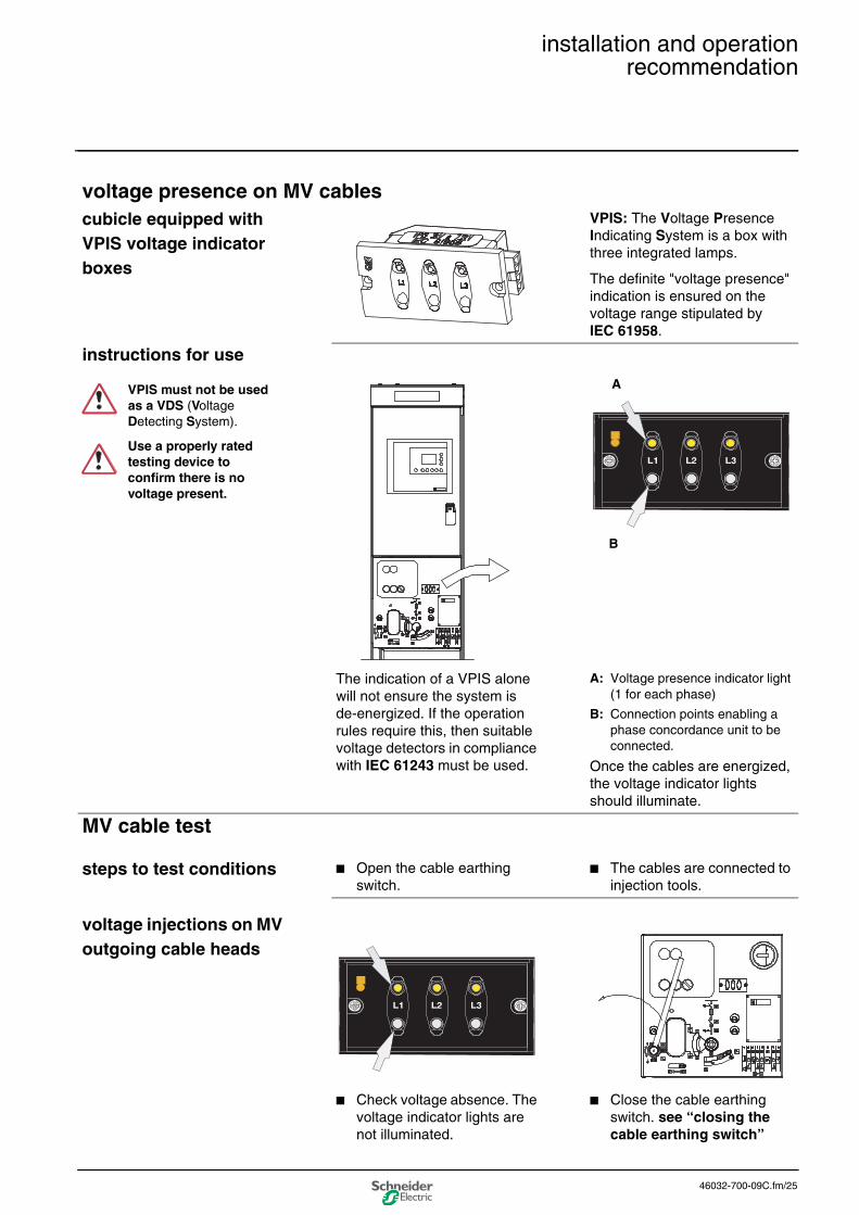
voltage presence on MV cablescubicle equipped with VPIS voltage indicator boxes
VPIS: The Voltage Presence Indicating System is a box with three integrated lamps.
The definite "voltage presence" indication is ensured on the voltage range stipulated by IEC 61958.
instructions for use
The indication of a VPIS alone will not ensure the system is de-energized. If the operation rules require this, then suitable voltage detectors in compliance with IEC 61243 must be used.
A: Voltage presence indicator light (1 for each phase)
B: Connection points enabling a phase concordance unit to be connected.
Once the cables are energized, the voltage indicator lights should illuminate.
MV cable test
steps to test conditions ■ Open the cable earthing switch.
■ The cables are connected to injection tools.
voltage injections on MV outgoing cable heads
■ Check voltage absence. The voltage indicator lights are not illuminated.
■ Close the cable earthing switch. see “closing the cable earthing switch”
VPIS must not be used as a VDS (Voltage Detecting System).
Use a properly rated testing device to confirm there is no voltage present.
A
B
46032-700-09C.fm/25
0installation and operationrecommendation
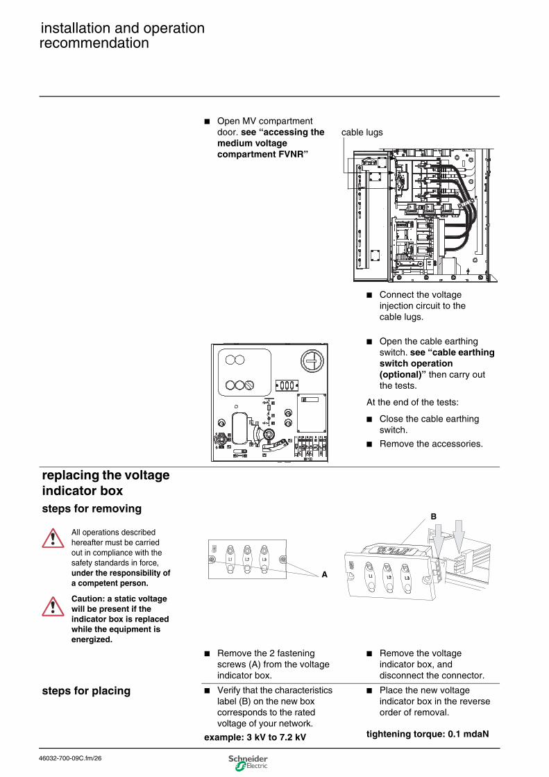
■ Open MV compartment door. see “accessing the medium voltage compartment FVNR”
■ Connect the voltage injection circuit to the cable lugs.
■ Open the cable earthing switch. see “cable earthing switch operation (optional)” then carry out the tests.
At the end of the tests:
■ Close the cable earthing switch.
■ Remove the accessories.
replacing the voltage indicator boxsteps for removing
■ Remove the 2 fastening screws (A) from the voltage indicator box.
■ Remove the voltage indicator box, and disconnect the connector.
steps for placing ■ Verify that the characteristics label (B) on the new box corresponds to the rated voltage of your network.
example: 3 kV to 7.2 kV
■ Place the new voltage indicator box in the reverse order of removal.
tightening torque: 0.1 mdaN
cable lugs
All operations described hereafter must be carried out in compliance with the safety standards in force, under the responsibility of a competent person.
Caution: a static voltage will be present if the indicator box is replaced while the equipment is energized.
A
B
46032-700-09C.fm/26

0
46032-700-09C.fm/27
0operating instructions
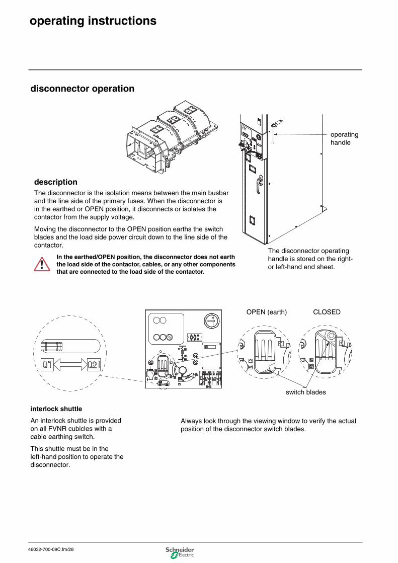
disconnector operation
interlock shuttle
An interlock shuttle is provided on all FVNR cubicles with a cable earthing switch.
This shuttle must be in the left-hand position to operate the disconnector.
Always look through the viewing window to verify the actual position of the disconnector switch blades.
operating handle
The disconnector operating handle is stored on the right- or left-hand end sheet.
descriptionThe disconnector is the isolation means between the main busbar and the line side of the primary fuses. When the disconnector is in the earthed or OPEN position, it disconnects or isolates the contactor from the supply voltage.
Moving the disconnector to the OPEN position earths the switch blades and the load side power circuit down to the line side of the contactor.
In the earthed/OPEN position, the disconnector does not earth the load side of the contactor, cables, or any other components that are connected to the load side of the contactor.
OPEN (earth) CLOSED
switch blades
46032-700-09C.fm/28
0operating instructions
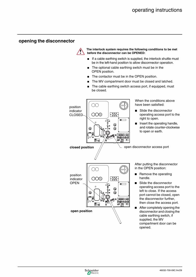
opening the disconnector
The interlock system requires the following conditions to be met before the disconnector can be OPENED:
■ If a cable earthing switch is supplied, the interlock shuttle must be in the left-hand position to allow disconnector operation.
■ The optional cable earthing switch must be in the OPEN position.
■ The contactor must be in the OPEN position.
■ The MV compartment door must be closed and latched.
■ The cable earthing switch access port, if equipped, must be closed.
When the conditions above have been satisfied:
■ Slide the disconnector operating access port to the right to open.
■ Insert the operating handle, and rotate counter-clockwise to open or earth.
After putting the disconnector in the OPEN position:
■ Remove the operating handle.
■ Slide the disconnector operating access port to the left to close. If the access port cannot be closed, open the disconnector further, then close the access port.
■ After completely opening the disconnector and closing the cable earthing switch, if supplied, the MV compartment door can be opened.
open disconnector access port
position indicator OPEN
closed position
open position
position indicator CLOSED
46032-700-09C.fm/29
0operating instructions
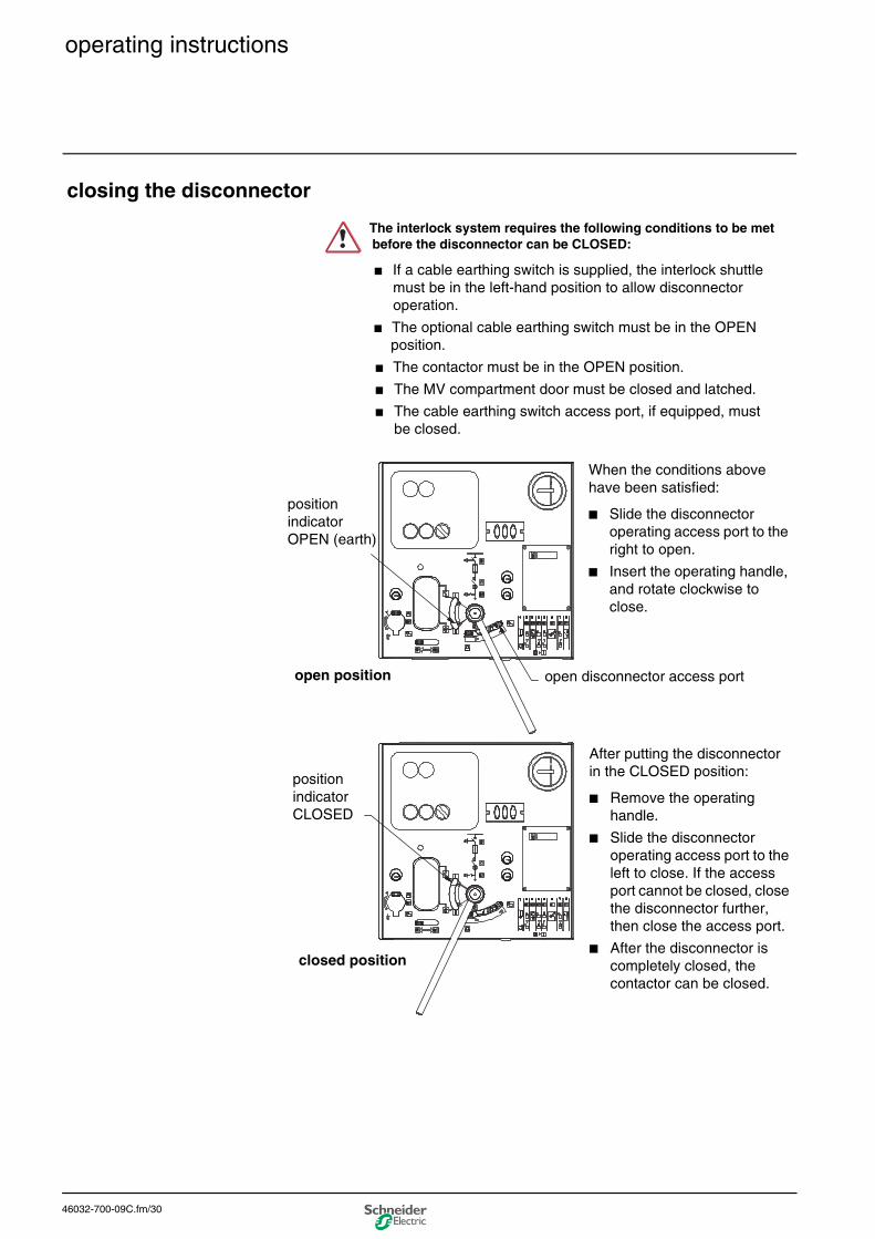
closing the disconnector
The interlock system requires the following conditions to be met before the disconnector can be CLOSED:
■ If a cable earthing switch is supplied, the interlock shuttle must be in the left-hand position to allow disconnector operation.
■ The optional cable earthing switch must be in the OPEN position.
■ The contactor must be in the OPEN position.
■ The MV compartment door must be closed and latched.
■ The cable earthing switch access port, if equipped, must be closed.
When the conditions above have been satisfied:
■ Slide the disconnector operating access port to the right to open.
■ Insert the operating handle, and rotate clockwise to close.
After putting the disconnector in the CLOSED position:
■ Remove the operating handle.
■ Slide the disconnector operating access port to the left to close. If the access port cannot be closed, close the disconnector further, then close the access port.
■ After the disconnector is completely closed, the contactor can be closed.
open disconnector access port
position indicator CLOSED
open position
closed position
position indicator OPEN (earth)
46032-700-09C.fm/30
0operating instructions
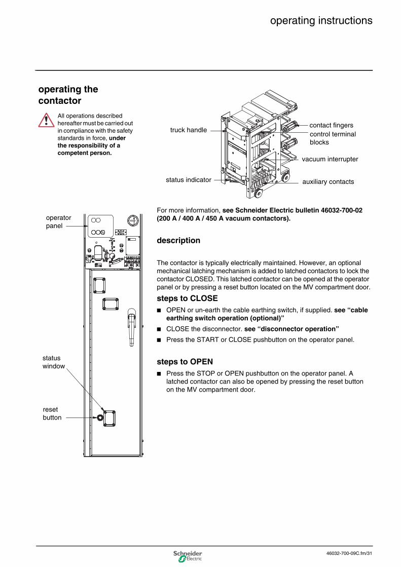
operating the contactor
For more information, see Schneider Electric bulletin 46032-700-02 (200 A / 400 A / 450 A vacuum contactors).
description
The contactor is typically electrically maintained. However, an optional mechanical latching mechanism is added to latched contactors to lock the contactor CLOSED. This latched contactor can be opened at the operator panel or by pressing a reset button located on the MV compartment door.
steps to CLOSE■ OPEN or un-earth the cable earthing switch, if supplied. see “cable
earthing switch operation (optional)”
■ CLOSE the disconnector. see “disconnector operation”
■ Press the START or CLOSE pushbutton on the operator panel.
steps to OPEN■ Press the STOP or OPEN pushbutton on the operator panel. A
latched contactor can also be opened by pressing the reset button on the MV compartment door.
All operations described hereafter must be carried out in compliance with the safety standards in force, under the responsibility of a competent person.
contact fingerscontrol terminal blocks
vacuum interrupter
auxiliary contacts
truck handle
status indicator
operator panel
status window
reset button
46032-700-09C.fm/31
0operating instructions
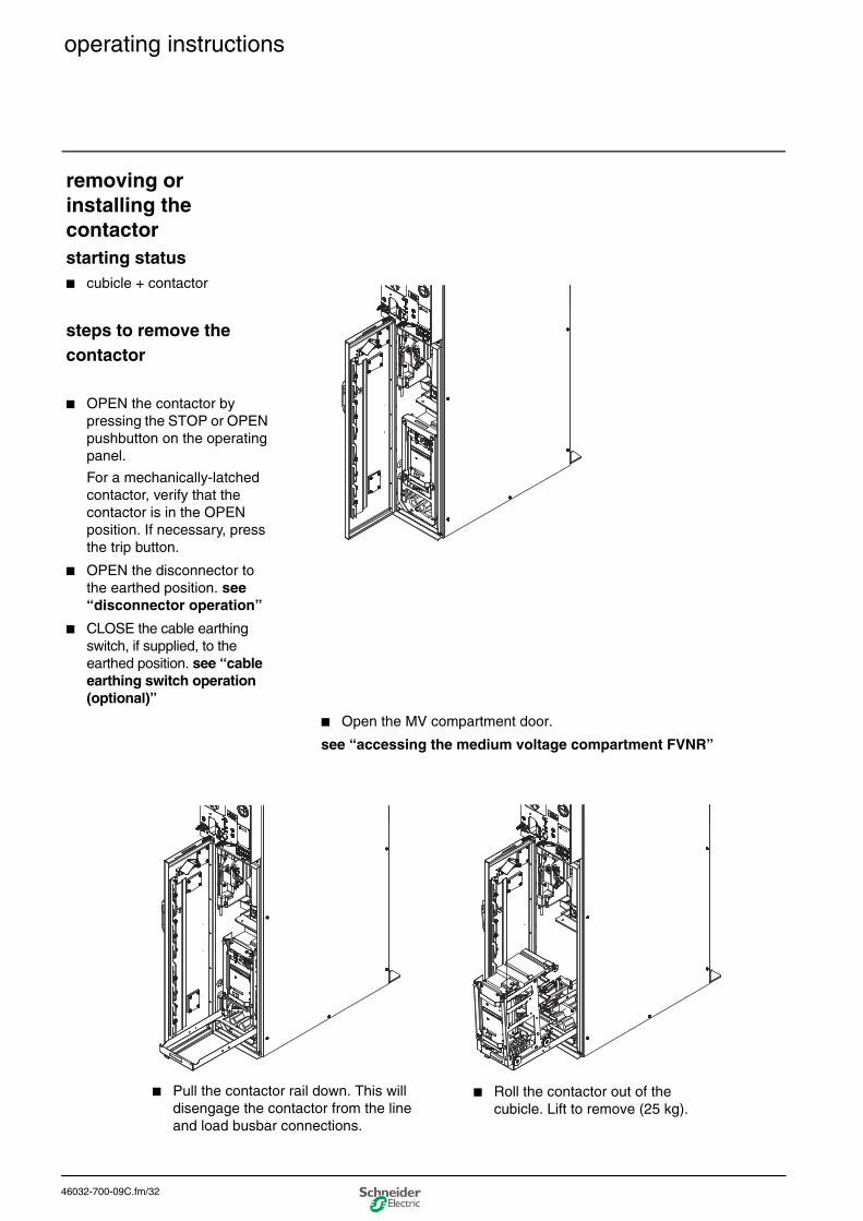
removing or installing the contactorstarting status■ cubicle + contactor
steps to remove the contactor
■ OPEN the contactor by pressing the STOP or OPEN pushbutton on the operating panel.
For a mechanically-latched contactor, verify that the contactor is in the OPEN position. If necessary, press the trip button.
■ OPEN the disconnector to the earthed position. see “disconnector operation”
■ CLOSE the cable earthing switch, if supplied, to the earthed position. see “cable earthing switch operation (optional)”
■ Open the MV compartment door.
see “accessing the medium voltage compartment FVNR”
■ Pull the contactor rail down. This will disengage the contactor from the line and load busbar connections.
■ Roll the contactor out of the cubicle. Lift to remove (25 kg).
46032-700-09C.fm/32
0operating instructions
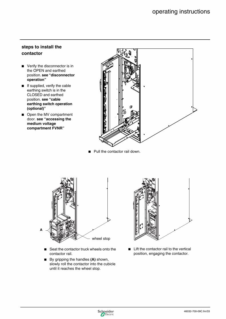
steps to install the contactor
■ Verify the disconnector is in the OPEN and earthed position. see “disconnector operation”
■ If supplied, verify the cable earthing switch is in the CLOSED and earthed position. see “cable earthing switch operation (optional)”
■ Open the MV compartment door. see “accessing the medium voltage compartment FVNR”
■ Pull the contactor rail down.
■ Seat the contactor truck wheels onto the contactor rail.
■ By gripping the handles (A) shown, slowly roll the contactor into the cubicle until it reaches the wheel stop.
■ Lift the contactor rail to the vertical position, engaging the contactor.
A
wheel stop
46032-700-09C.fm/33
0operating instructions
back light assembly (optional)
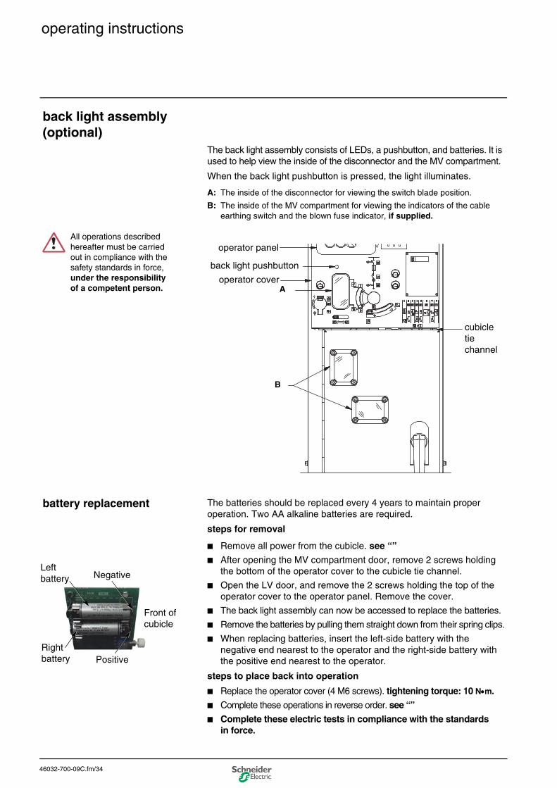
The back light assembly consists of LEDs, a pushbutton, and batteries. It is used to help view the inside of the disconnector and the MV compartment.
When the back light pushbutton is pressed, the light illuminates.
A: The inside of the disconnector for viewing the switch blade position.
B: The inside of the MV compartment for viewing the indicators of the cable earthing switch and the blown fuse indicator, if supplied.
battery replacement The batteries should be replaced every 4 years to maintain proper operation. Two AA alkaline batteries are required.
steps for removal
■ Remove all power from the cubicle. see “”
■ After opening the MV compartment door, remove 2 screws holding the bottom of the operator cover to the cubicle tie channel.
■ Open the LV door, and remove the 2 screws holding the top of the operator cover to the operator panel. Remove the cover.
■ The back light assembly can now be accessed to replace the batteries.
■ Remove the batteries by pulling them straight down from their spring clips.
■ When replacing batteries, insert the left-side battery with the negative end nearest to the operator and the right-side battery with the positive end nearest to the operator.
steps to place back into operation
■ Replace the operator cover (4 M6 screws). tightening torque: 10 N•m.
■ Complete these operations in reverse order. see “”
■ Complete these electric tests in compliance with the standards in force.
All operations described hereafter must be carried out in compliance with the safety standards in force, under the responsibility of a competent person.
cubicle tie channel
operator panel
back light pushbutton
operator coverA
B
Left battery
Right battery
Negative
Positive
Front of cubicle
46032-700-09C.fm/34
0operating instructions
cable earthing switch operation (optional)
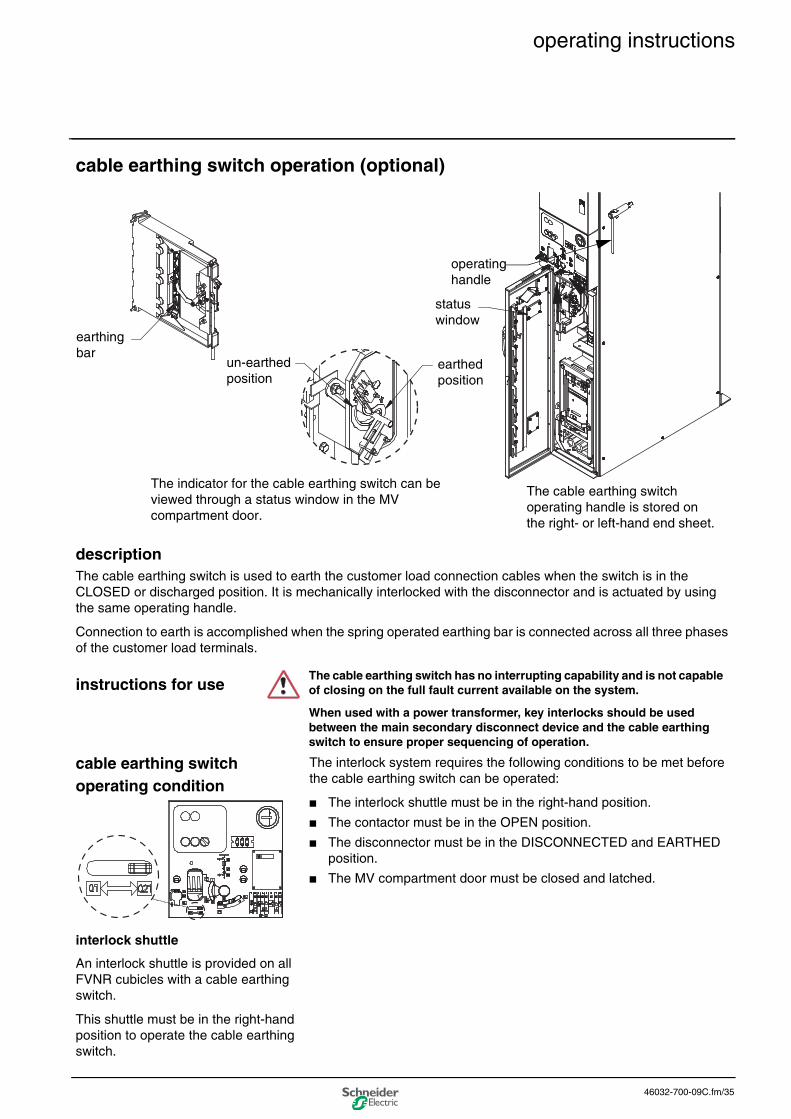
descriptionThe cable earthing switch is used to earth the customer load connection cables when the switch is in the CLOSED or discharged position. It is mechanically interlocked with the disconnector and is actuated by using the same operating handle.
Connection to earth is accomplished when the spring operated earthing bar is connected across all three phases of the customer load terminals.
instructions for use
cable earthing switch operating condition
interlock shuttle
An interlock shuttle is provided on all FVNR cubicles with a cable earthing switch.
This shuttle must be in the right-hand position to operate the cable earthing switch.
The interlock system requires the following conditions to be met before the cable earthing switch can be operated:
■ The interlock shuttle must be in the right-hand position.
■ The contactor must be in the OPEN position.
■ The disconnector must be in the DISCONNECTED and EARTHED position.
■ The MV compartment door must be closed and latched.
?
earthing bar
status window
The indicator for the cable earthing switch can be viewed through a status window in the MV compartment door.
operating handle
un-earthed position
earthed position
The cable earthing switch operating handle is stored on the right- or left-hand end sheet.
The cable earthing switch has no interrupting capability and is not capable of closing on the full fault current available on the system.
When used with a power transformer, key interlocks should be used between the main secondary disconnect device and the cable earthing switch to ensure proper sequencing of operation.
46032-700-09C.fm/35
0operating instructions
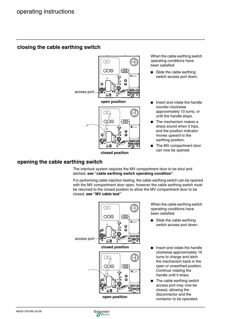
closing the cable earthing switch
opening the cable earthing switchThe interlock system requires the MV compartment door to be shut and latched. see “cable earthing switch operating condition”
For performing cable injection testing, the cable earthing switch can be opened with the MV compartment door open, however the cable earthing switch must be returned to the closed position to allow the MV compartment door to be closed. see “MV cable test”
When the cable earthing switch operating conditions have been satisfied:
■ Slide the cable earthing switch access port down.
■ Insert and rotate the handle counter-clockwise approximately 10 turns, or until the handle stops.
■ The mechanism makes a sharp sound when it trips, and the position indicator moves upward to the earthing position.
■ The MV compartment door can now be opened.
open position
closed position
access port
When the cable earthing switch operating conditions have been satisfied:
■ Slide the cable earthing switch access port down.
■ Insert and rotate the handle clockwise approximately 10 turns to charge and latch the mechanism back in the open or unearthed position. Continue rotating the handle until it stops.
■ The cable earthing switch access port may now be closed, allowing the disconnector and the contactor to be operated.
closed position
open position
access port
46032-700-09C.fm/36
0operating instructions
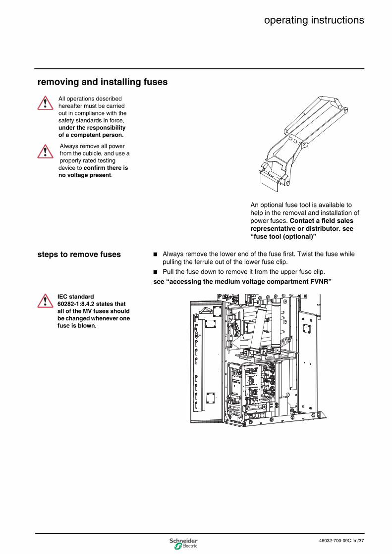
removing and installing fuses
An optional fuse tool is available to help in the removal and installation of power fuses. Contact a field sales representative or distributor. see “fuse tool (optional)”
steps to remove fuses ■ Always remove the lower end of the fuse first. Twist the fuse while pulling the ferrule out of the lower fuse clip.
■ Pull the fuse down to remove it from the upper fuse clip.
see “accessing the medium voltage compartment FVNR”
All operations described hereafter must be carried out in compliance with the safety standards in force, under the responsibility of a competent person.
Always remove all power from the cubicle, and use a properly rated testing device to confirm there is no voltage present.
IEC standard 60282-1:8.4.2 states that all of the MV fuses should be changed whenever one fuse is blown.
46032-700-09C.fm/37
0operating instructions
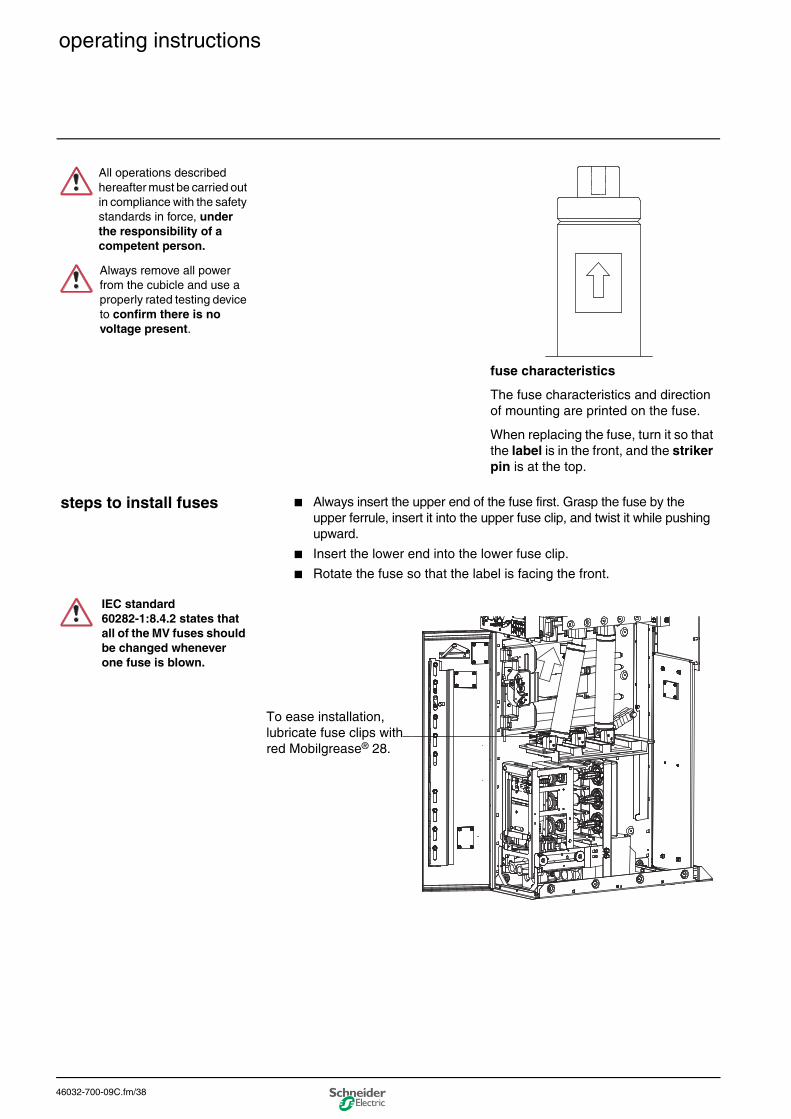
fuse characteristics
The fuse characteristics and direction of mounting are printed on the fuse.
When replacing the fuse, turn it so that the label is in the front, and the striker pin is at the top.
steps to install fuses ■ Always insert the upper end of the fuse first. Grasp the fuse by the upper ferrule, insert it into the upper fuse clip, and twist it while pushing upward.
■ Insert the lower end into the lower fuse clip.
■ Rotate the fuse so that the label is facing the front.
All operations described hereafter must be carried out in compliance with the safety standards in force, under the responsibility of a competent person.
Always remove all power from the cubicle and use a properly rated testing device to confirm there is no voltage present.
IEC standard 60282-1:8.4.2 states that all of the MV fuses should be changed whenever one fuse is blown.
To ease installation, lubricate fuse clips with red Mobilgrease® 28.
46032-700-09C.fm/38
0operating instructions
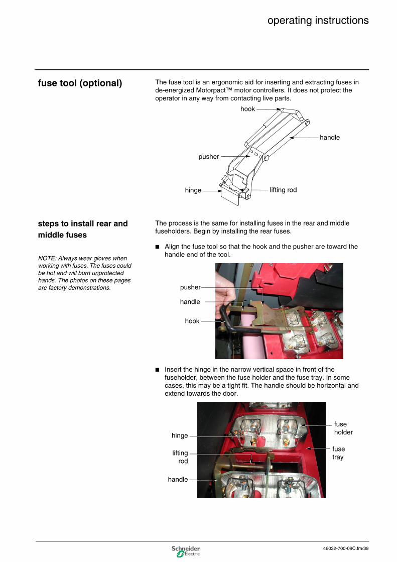
fuse tool (optional) The fuse tool is an ergonomic aid for inserting and extracting fuses in de-energized Motorpact™ motor controllers. It does not protect the operator in any way from contacting live parts.
steps to install rear and middle fuses
The process is the same for installing fuses in the rear and middle fuseholders. Begin by installing the rear fuses.
NOTE: Always wear gloves when working with fuses. The fuses could be hot and will burn unprotected hands. The photos on these pages are factory demonstrations.
■ Align the fuse tool so that the hook and the pusher are toward the handle end of the tool.
■ Insert the hinge in the narrow vertical space in front of the fuseholder, between the fuse holder and the fuse tray. In some cases, this may be a tight fit. The handle should be horizontal and extend towards the door.
hinge
handle
lifting rod
hook
pusher
hook
pusher
handle
hinge
handle
liftingrod
fuse holder
fuse tray
46032-700-09C.fm/39
0operating instructions
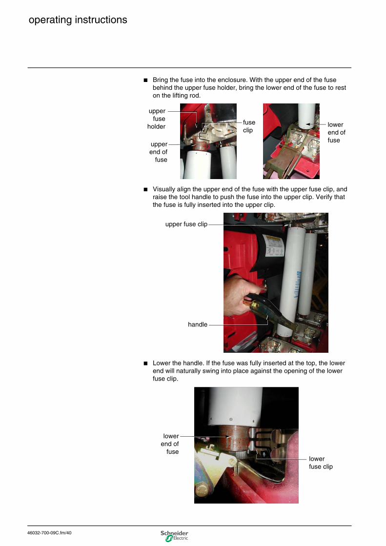
■ Bring the fuse into the enclosure. With the upper end of the fuse behind the upper fuse holder, bring the lower end of the fuse to rest on the lifting rod.
■ Visually align the upper end of the fuse with the upper fuse clip, and raise the tool handle to push the fuse into the upper clip. Verify that the fuse is fully inserted into the upper clip.
■ Lower the handle. If the fuse was fully inserted at the top, the lower end will naturally swing into place against the opening of the lower fuse clip.
upperend of
fuse
lower end of fuse
upperfuse
holderfuse clip
upper fuse clip
handle
lower fuse clip
lowerend of
fuse
46032-700-09C.fm/40
0operating instructions
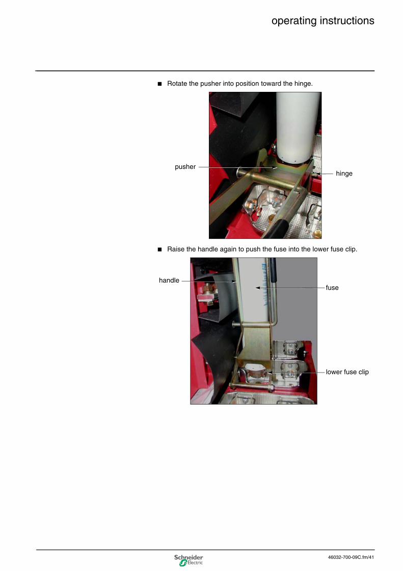
■ Rotate the pusher into position toward the hinge.
■ Raise the handle again to push the fuse into the lower fuse clip.
pusherhinge
handlefuse
lower fuse clip
46032-700-09C.fm/41
0operating instructions
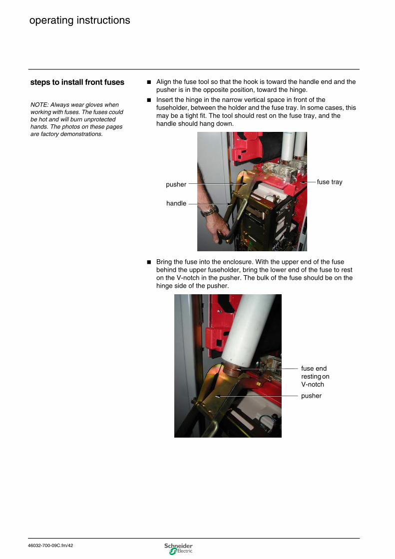
steps to install front fuses
NOTE: Always wear gloves when working with fuses. The fuses could be hot and will burn unprotected hands. The photos on these pages are factory demonstrations.
■ Align the fuse tool so that the hook is toward the handle end and the pusher is in the opposite position, toward the hinge.
■ Insert the hinge in the narrow vertical space in front of the fuseholder, between the holder and the fuse tray. In some cases, this may be a tight fit. The tool should rest on the fuse tray, and the handle should hang down.
■ Bring the fuse into the enclosure. With the upper end of the fuse behind the upper fuseholder, bring the lower end of the fuse to rest on the V-notch in the pusher. The bulk of the fuse should be on the hinge side of the pusher.
pusher
handle
fuse tray
fuse end resting on V-notch
pusher
46032-700-09C.fm/42

0operating instructions
■ Visually align the upper end of the fuse with the upper clip, and raise the tool handle to push the fuse into the upper clip. Verify that the fuse is fully inserted into the upper clip.
■ Lower the handle. If the fuse was fully inserted at the top, the lower end will naturally swing into place against the opening of the lower fuse clip.
■ Raise the handle again to push the fuse into the lower fuse clip.
lower fuse clip
fuse tool
fuse
handle
46032-700-09C.fm/43
0operating instructions
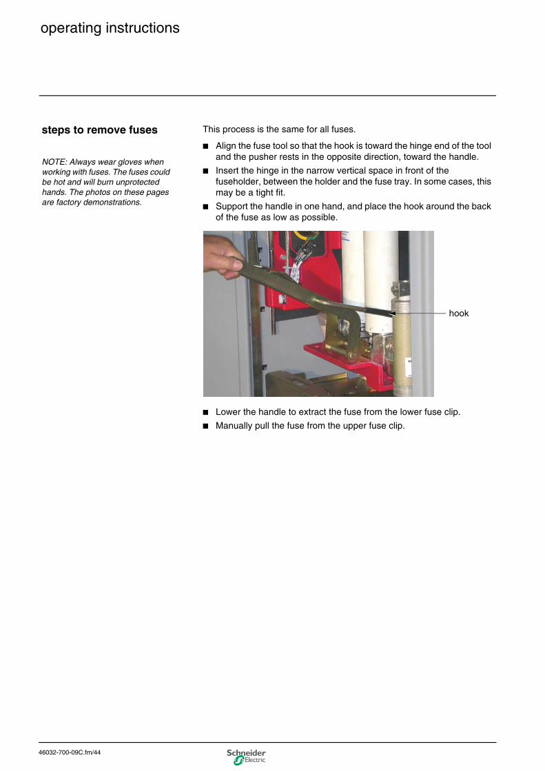
steps to remove fuses This process is the same for all fuses.
NOTE: Always wear gloves when working with fuses. The fuses could be hot and will burn unprotected hands. The photos on these pages are factory demonstrations.
■ Align the fuse tool so that the hook is toward the hinge end of the tool and the pusher rests in the opposite direction, toward the handle.
■ Insert the hinge in the narrow vertical space in front of the fuseholder, between the holder and the fuse tray. In some cases, this may be a tight fit.
■ Support the handle in one hand, and place the hook around the back of the fuse as low as possible.
■ Lower the handle to extract the fuse from the lower fuse clip.
■ Manually pull the fuse from the upper fuse clip.
hook
46032-700-09C.fm/44
0operating instructions
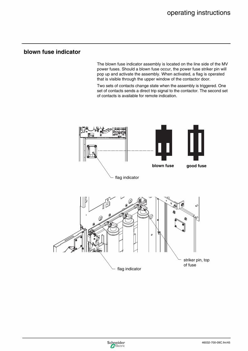
blown fuse indicator
The blown fuse indicator assembly is located on the line side of the MV power fuses. Should a blown fuse occur, the power fuse striker pin will pop up and activate the assembly. When activated, a flag is operated that is visible through the upper window of the contactor door.
Two sets of contacts change state when the assembly is triggered. One set of contacts sends a direct trip signal to the contactor. The second set of contacts is available for remote indication.
flag indicator
blown fuse good fuse
flag indicator
striker pin, top of fuse
46032-700-09C.fm/45
0operating instructions
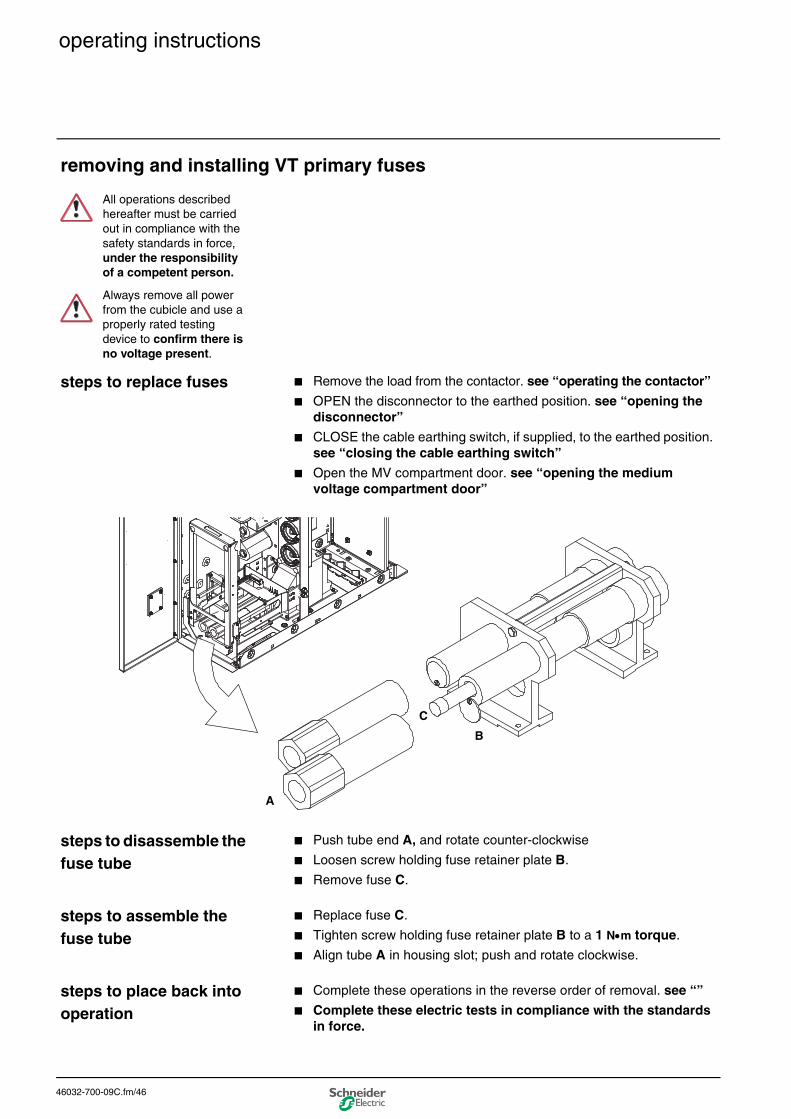
removing and installing VT primary fuses
steps to replace fuses ■ Remove the load from the contactor. see “operating the contactor”
■ OPEN the disconnector to the earthed position. see “opening the disconnector”
■ CLOSE the cable earthing switch, if supplied, to the earthed position. see “closing the cable earthing switch”
■ Open the MV compartment door. see “opening the medium voltage compartment door”
steps to disassemble the fuse tube
■ Push tube end A, and rotate counter-clockwise
■ Loosen screw holding fuse retainer plate B.
■ Remove fuse C.
steps to assemble the fuse tube
■ Replace fuse C.
■ Tighten screw holding fuse retainer plate B to a 1 N•m torque.
■ Align tube A in housing slot; push and rotate clockwise.
steps to place back into operation
■ Complete these operations in the reverse order of removal. see “”
■ Complete these electric tests in compliance with the standards in force.
All operations described hereafter must be carried out in compliance with the safety standards in force, under the responsibility of a competent person.
Always remove all power from the cubicle and use a properly rated testing device to confirm there is no voltage present.
A
B
C
46032-700-09C.fm/46
0operating instructions
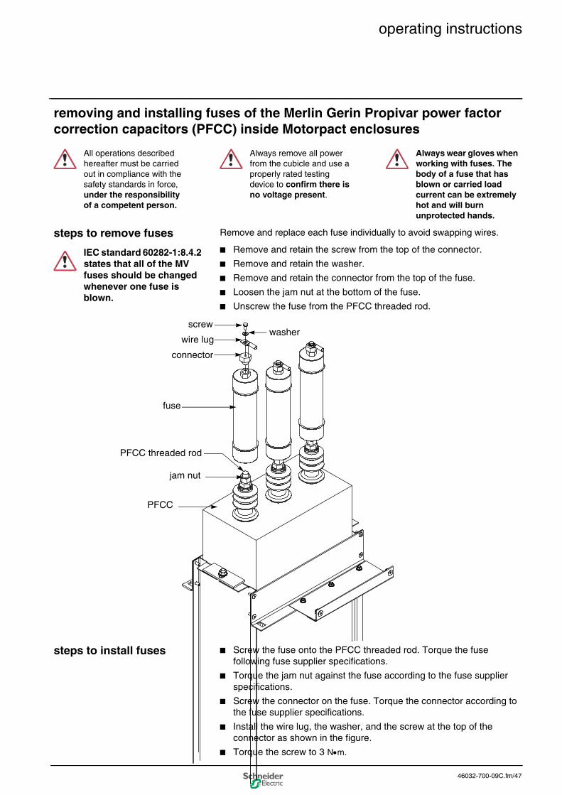
removing and installing fuses of the Merlin Gerin Propivar power factor correction capacitors (PFCC) inside Motorpact enclosures
steps to remove fuses Remove and replace each fuse individually to avoid swapping wires.
■ Remove and retain the screw from the top of the connector.
■ Remove and retain the washer.
■ Remove and retain the connector from the top of the fuse.
■ Loosen the jam nut at the bottom of the fuse.
■ Unscrew the fuse from the PFCC threaded rod.
steps to install fuses ■ Screw the fuse onto the PFCC threaded rod. Torque the fuse following fuse supplier specifications.
■ Torque the jam nut against the fuse according to the fuse supplier specifications.
■ Screw the connector on the fuse. Torque the connector according to the fuse supplier specifications.
■ Install the wire lug, the washer, and the screw at the top of the connector as shown in the figure.
■ Torque the screw to 3 N•m.
All operations described hereafter must be carried out in compliance with the safety standards in force, under the responsibility of a competent person.
Always remove all power from the cubicle and use a properly rated testing device to confirm there is no voltage present.
Always wear gloves when working with fuses. The body of a fuse that has blown or carried load current can be extremely hot and will burn unprotected hands.
IEC standard 60282-1:8.4.2 states that all of the MV fuses should be changed whenever one fuse is blown.
washerscrew
wire lug
connector
fuse
PFCC threaded rod
jam nut
PFCC
46032-700-09C.fm/47
0operating instructions
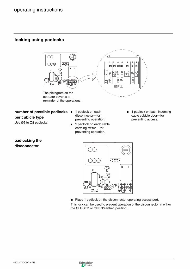
locking using padlocks
number of possible padlocks per cubicle type Use Ø6 to Ø8 padlocks.
■ 1 padlock on each disconnector—for preventing operation.
■ 1 padlock on each cable earthing switch—for preventing operation.
■ 1 padlock on each incoming cable cubicle door—for preventing access.
padlocking the disconnector
■ Place 1 padlock on the disconnector operating access port.
This lock can be used to prevent operation of the disconnector in either the CLOSED or OPEN/earthed position.
The pictogram on the operator cover is a reminder of the operations.
46032-700-09C.fm/48
0operating instructions
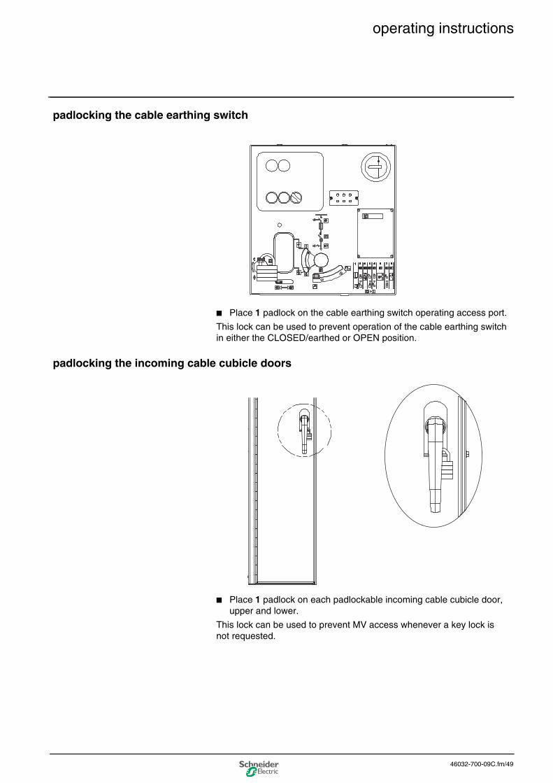
padlocking the cable earthing switch
■ Place 1 padlock on the cable earthing switch operating access port.
This lock can be used to prevent operation of the cable earthing switch in either the CLOSED/earthed or OPEN position.
padlocking the incoming cable cubicle doors
■ Place 1 padlock on each padlockable incoming cable cubicle door, upper and lower.
This lock can be used to prevent MV access whenever a key lock is not requested.
46032-700-09C.fm/49
0operating instructions
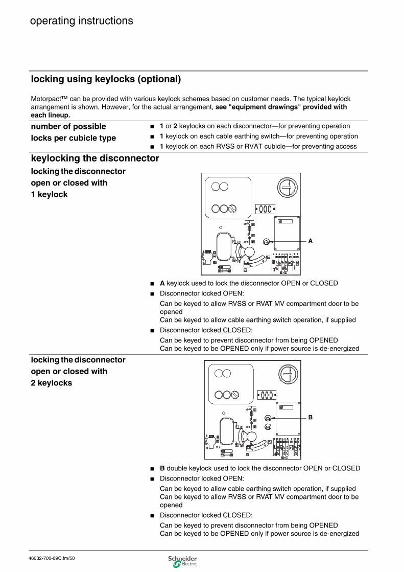
locking using keylocks (optional)
Motorpact™ can be provided with various keylock schemes based on customer needs. The typical keylock arrangement is shown. However, for the actual arrangement, see "equipment drawings" provided with each lineup.
number of possible locks per cubicle type
■ 1 or 2 keylocks on each disconnector—for preventing operation
■ 1 keylock on each cable earthing switch—for preventing operation
■ 1 keylock on each RVSS or RVAT cubicle—for preventing access
keylocking the disconnectorlocking the disconnector open or closed with 1 keylock
■ A keylock used to lock the disconnector OPEN or CLOSED
■ Disconnector locked OPEN:
Can be keyed to allow RVSS or RVAT MV compartment door to be openedCan be keyed to allow cable earthing switch operation, if supplied
■ Disconnector locked CLOSED:
Can be keyed to prevent disconnector from being OPENEDCan be keyed to be OPENED only if power source is de-energized
locking the disconnector open or closed with 2 keylocks
■ B double keylock used to lock the disconnector OPEN or CLOSED
■ Disconnector locked OPEN:
Can be keyed to allow cable earthing switch operation, if suppliedCan be keyed to allow RVSS or RVAT MV compartment door to be opened
■ Disconnector locked CLOSED:
Can be keyed to prevent disconnector from being OPENEDCan be keyed to be OPENED only if power source is de-energized
A
B
46032-700-09C.fm/50

0operating instructions
locking the cable earthing switch open or closed
■ C keylock used to lock the cable earthing switch OPEN or CLOSED
■ Cable earthing switch locked OPEN:
Can be keyed to allow disconnector operation
■ Cable earthing switch locked CLOSED:
Can be keyed to allow RVSS or RVAT MV compartment door to be opened
C
46032-700-09C.fm/51

0operating instructions
RVAT (reduced voltage autotransformer)
description The Reduced Voltage Autotransformer (RVAT) is used to provide a reduced voltage to the motor terminals during starting. This is achieved by the use of an autotransformer. Typically two types of autotransformers are available.
■ Tapped—permits changing taps to change the output voltage to the motor terminals
■ Non-tapped—specifically designed for the application and motor
In this manual, the tapped autotransformer is shown and discussed. For an application using a non-tapped autotransformer, all information provided is applicable other than the instruction for changing the tap settings.
The cubicle size of an RVAT is dependent upon the transformer rating. The RVAT is always controlled from an FVNR cubicle adjacent to the left and the motor cable connections are made in this main controller cubicle.
Each RVAT cubicle is equipped with the following:
■ run contactor
■ start contactor
■ autotransformer
■ surge arresters
RVAT interiorRVAT exterior
start contactor
run contactor
autotransformer
door latch keylock
46032-700-09C.fm/52
0operating instructions
limited duty cycle rating The reduced voltage starters contain an autotransformer with a limited duty cycle rating. Unless otherwise noted, these devices are rated per IEC 60076-11. Longer start times or more frequent starts will shorten the life of this device.
keylocks on an RVAT
keylocking with disconnector (without cable earthing switch)
The RVAT cubicle is supplied with key interlocks between the disconnector in the main controller cubicle and the start and run contactor compartments and the autotransformer compartment.
With the disconnector in the CLOSED position, the key is held captive. During maintenance, the disconnector can be OPENED/earthed and the key removed for access to the RVAT cubicle. see “disconnector operation” and “accessing the medium voltage compartments RVAT or RVSS”
keylocking (with cable earthing switch)
When a cable earthing switch is supplied, the RVAT cubicle is supplied with key interlocks between the cable earthing switch in the main controller cubicle and the start and run contactor compartments, and the autotransformer compartment.
With the cable earthing switch in the OPEN or unearthed position, the key is held captive. During maintenance, the cable earthing switch can be CLOSED/earthed and the key removed for access to the RVAT cubicle. see “cable earthing switch operation (optional)” and “accessing the medium voltage compartments RVAT or RVSS”
A spare key is supplied with every RVAT cubicle. For safe operation, only 1 key should be used. The spare key should be stored away from the equipment and only used if 1 key is lost.
Using both keys could give access to live parts and could cause death or serious injury.
46032-700-09C.fm/53
0operating instructions
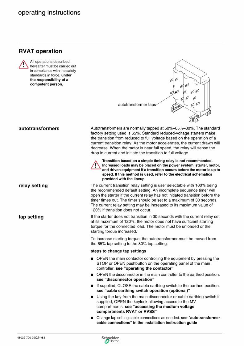
RVAT operation
autotransformers Autotransformers are normally tapped at 50%–65%–80%. The standard factory setting used is 65%. Standard reduced-voltage starters make the transition from reduced to full voltage based on the operation of a current transition relay. As the motor accelerates, the current drawn will decrease. When the motor is near full speed, the relay will sense the drop in current and initiate the transition to full voltage.
relay setting The current transition relay setting is user selectable with 100% being the recommended default setting. An incomplete sequence timer will open the starter if the current relay has not initiated transition before the timer times out. The timer should be set to a maximum of 30 seconds. The current relay setting may be increased to its maximum value of 120% if transition does not occur.
tap setting If the starter does not transition in 30 seconds with the current relay set at its maximum of 120%, the motor does not have sufficient starting torque for the connected load. The motor must be unloaded or the starting torque increased.
To increase starting torque, the autotransformer must be moved from the 65% tap setting to the 80% tap setting.
steps to change tap settings
■ OPEN the main contactor controlling the equipment by pressing the STOP or OPEN pushbutton on the operating panel of the main controller. see “operating the contactor”
■ OPEN the disconnector in the main controller to the earthed position. see “disconnector operation”
■ If supplied, CLOSE the cable earthing switch to the earthed position. see “cable earthing switch operation (optional)”
■ Using the key from the main disconnector or cable earthing switch if supplied, OPEN the keylock allowing access to the MV compartments. see “accessing the medium voltage compartments RVAT or RVSS”
■ Change tap setting cable connections as needed. see "autotransformer cable connections" in the installation instruction guide
All operations described hereafter must be carried out in compliance with the safety standards in force, under the responsibility of a competent person.
autotransformer taps
Transition based on a simple timing relay is not recommended. Increased loads may be placed on the power system, starter, motor, and driven equipment if a transition occurs before the motor is up to speed. If this method is used, refer to the electrical schematics provided with the lineup.
46032-700-09C.fm/54
0operating instructions
S
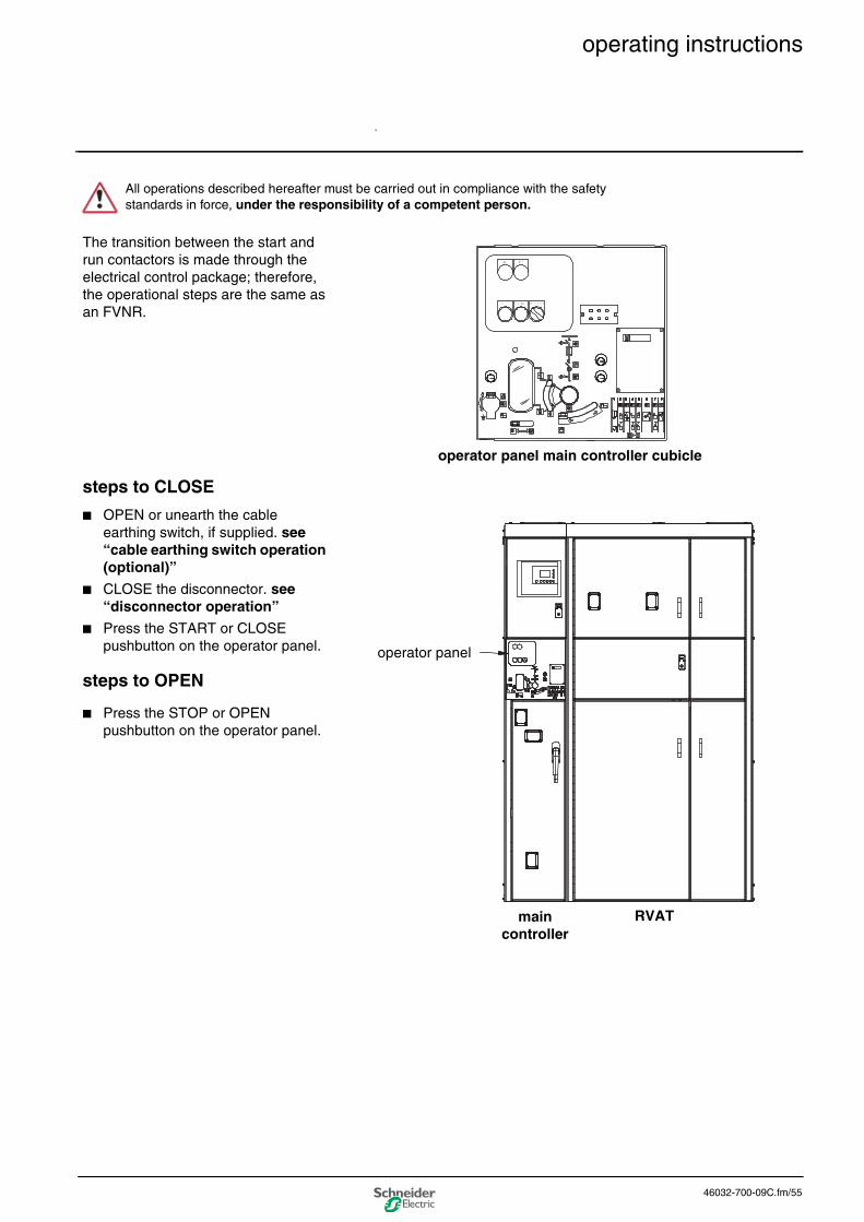
The transition between the start and run contactors is made through the electrical control package; therefore, the operational steps are the same as an FVNR.
steps to CLOSE
■ OPEN or unearth the cable earthing switch, if supplied. see “cable earthing switch operation (optional)”
■ CLOSE the disconnector. see “disconnector operation”
■ Press the START or CLOSE pushbutton on the operator panel.
steps to OPEN
■ Press the STOP or OPEN pushbutton on the operator panel.
All operations described hereafter must be carried out in compliance with the safety standards in force, under the responsibility of a competent person.
$( 4 $+ + 4 0
4# 4" "
34* 3
operator panel main controller cubicle
operator panel
main controller
RVAT
46032-700-09C.fm/55
0operating instructions
RVSS (reduced voltage soft start)
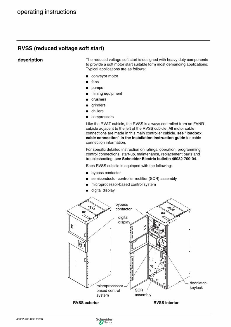
description The reduced voltage soft start is designed with heavy duty components to provide a soft motor start suitable form most demanding applications. Typical applications are as follows:
■ conveyor motor
■ fans
■ pumps
■ mining equipment
■ crushers
■ grinders
■ chillers
■ compressors
Like the RVAT cubicle, the RVSS is always controlled from an FVNR cubicle adjacent to the left of the RVSS cubicle. All motor cable connections are made in this main controller cubicle. see "loadbox cable connection" in the installation instruction guide for cable connection information.
For specific detailed instruction on ratings, operation, programming, control connections, start-up, maintenance, replacement parts and troubleshooting, see Schneider Electric bulletin 46032-700-04.
Each RVSS cubicle is equipped with the following:
■ bypass contactor
■ semiconductor controller rectifier (SCR) assembly
■ microprocessor-based control system
■ digital display
RVSS interiorRVSS exterior
bypass contactor
digital display
microprocessor based control system
SCR assembly
door latch keylock
46032-700-09C.fm/56
0operating instructions
keylocks on an RVSSkeylocking with disconnector (without cable earthing switch)
The RVSS cubicle is supplied with key interlocks between the disconnector in the main controller cubicle and the bypass contactor compartment.
With the disconnector in the CLOSED position, the key is held captive. During maintenance, the disconnector can be OPENED/earthed and the key removed for access to the RVSS cubicle. see “disconnector operation” and “accessing the busbar compartments RVAT or RVSS”
keylocking (with cable earthing switch)
When a cable earthing switch is supplied, the RVSS cubicle is supplied with key interlocks between the cable earthing switch in the main controller cubicle and the bypass contactor compartment and soft start power compartment.
With the cable earthing switch in the OPEN or unearthed position, the key is held captive. During maintenance, the cable earthing switch can be CLOSED/earthed and the key removed for access to the RVSS cubicle. see “cable earthing switch operation (optional)” and “accessing the medium voltage compartments RVAT or RVSS”
A spare key is supplied with every RVSS cubicle. For safe operation, only 1 key should be used. The spare key should be stored away from the equipment and only used if 1 key is lost.
Using both keys could give access to live parts and could cause death or serious injury.
46032-700-09C.fm/57
0operating instructions
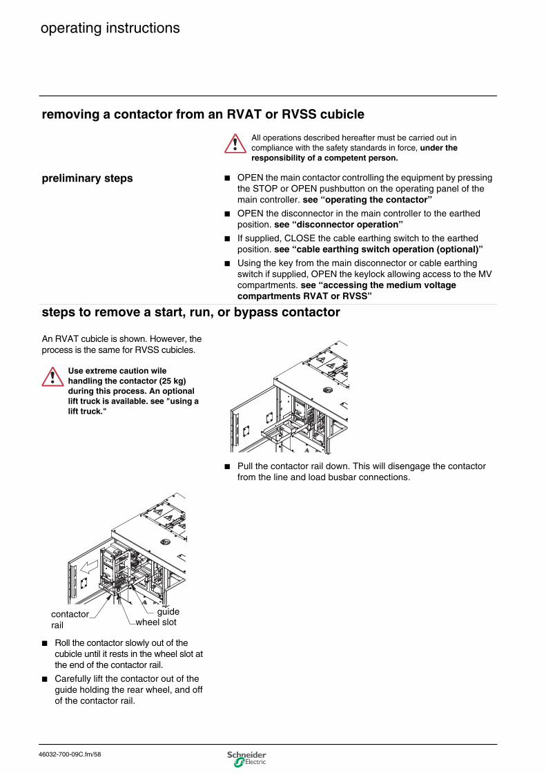
removing a contactor from an RVAT or RVSS cubicle
preliminary steps ■ OPEN the main contactor controlling the equipment by pressing the STOP or OPEN pushbutton on the operating panel of the main controller. see “operating the contactor”
■ OPEN the disconnector in the main controller to the earthed position. see “disconnector operation”
■ If supplied, CLOSE the cable earthing switch to the earthed position. see “cable earthing switch operation (optional)”
■ Using the key from the main disconnector or cable earthing switch if supplied, OPEN the keylock allowing access to the MV compartments. see “accessing the medium voltage compartments RVAT or RVSS”
steps to remove a start, run, or bypass contactor
An RVAT cubicle is shown. However, the process is the same for RVSS cubicles.
■ Pull the contactor rail down. This will disengage the contactor from the line and load busbar connections.
■ Roll the contactor slowly out of the cubicle until it rests in the wheel slot at the end of the contactor rail.
■ Carefully lift the contactor out of the guide holding the rear wheel, and off of the contactor rail.
All operations described hereafter must be carried out in compliance with the safety standards in force, under the responsibility of a competent person.
Use extreme caution wile handling the contactor (25 kg) during this process. An optional lift truck is available. see "using a lift truck."
wheel slotcontactor rail
guide
46032-700-09C.fm/58
0operating instructions
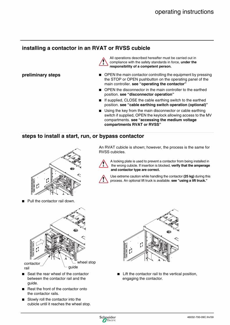
installing a contactor in an RVAT or RVSS cubicle
preliminary steps ■ OPEN the main contactor controlling the equipment by pressing the STOP or OPEN pushbutton on the operating panel of the main controller. see “operating the contactor”
■ OPEN the disconnector in the main controller to the earthed position. see “disconnector operation”
■ If supplied, CLOSE the cable earthing switch to the earthed position. see “cable earthing switch operation (optional)”
■ Using the key from the main disconnector or cable earthing switch if supplied, OPEN the keylock allowing access to the MV compartments. see “accessing the medium voltage compartments RVAT or RVSS”
steps to install a start, run, or bypass contactor
An RVAT cubicle is shown; however, the process is the same for RVSS cubicles.
■ Pull the contactor rail down.
■ Seat the rear wheel of the contactor between the contactor rail and the guide.
■ Rest the front of the contactor onto the contactor rails.
■ Slowly roll the contactor into the cubicle until it reaches the wheel stop.
■ Lift the contactor rail to the vertical position, engaging the contactor.
All operations described hereafter must be carried out in compliance with the safety standards in force, under the responsibility of a competent person.
A locking plate is used to prevent a contactor from being installed in the wrong cubicle. If insertion is blocked, verify that the amperage and contactor type are correct.
Use extreme caution while handling the contactor (25 kg) during this process. An optional lift truck is available. see "using a lift truck."
contactor rail guide
wheel stop
46032-700-09C.fm/59

0
0operating instructionsusing a lift truck (optional) A lift truck is available for removing or installing contactors in an RVAT or RVSS cubicle. Contact your local field sales office or distributor.
Use this device with all guidelines and processes explained in:
■ “removing a contactor from an RVAT or RVSS cubicle” ■ “installing a contactor in an RVAT or RVSS cubicle”
removing contactor with a lift truck
contactor
lift truck
46032-700-09C.fm/60

0operating instructions
MDT107 thermal diagnostic system (optional)
The MDT107 Thermal Diagnostic System is mounted in the equipment at the factory for shipping. Wiring connections must be completed and tested on site before putting the equipment into service.
description The MDT107 Thermal Diagnostic system is used to measure the temperature of medium voltage circuits. Using Schneider Electric patented technology, the MDT107 system provides:
■ continuous monitoring of temperature rise of power circuits at upper fuse holders and customer cable connections.
■ triggering of a pre-alarm, then an alarm by activation of outputs on dry contacts.
■ visual indication of the zone and phase in which a temperature rise exceeds a set threshold.
The MDT107 system includes:
■ An MDT107 electronic module mounted on a DIN rail in the LV cabinet of the Motorpact™ unit. The module transmits calibrated impulses to 1 or more circuits via optical fibers. The calculation of a circuit’s temperature is based on the impulses the circuit sends back to the module.
■ 2 CFO733 temperature sensors. Each of these factory-built assemblies includes 3 sensor heads, 3 optical fibers, and the connector for connecting to the readout module. The sensor heads are made from a light-sensitive material whose fluorescence time depends on temperature. The connector incorporates an optical-electric conversion circuit, eliminating the need for optical connections during installation.
■ Accessories for factory installation of the sensors in the MV panel.
46032-700-09C.fm/61
0operating instructions
functions The MDT107 module performs the following functions:
monitoring of temperature buildup in 2 zones
Each CFO733 sensor corresponds to a 3-point zone to be monitored in the panel, monitoring being based on temperature rise. The module measures the temperature at 3 points per zone, as well as the ambient temperature in order to calculate the temperature rise for each point.
Given the temperature differences between the inside of the LV cabinet and the outside of the enclosure, correction of the ambient temperature measured by the module is configured by means of an additional setting.
Comparison monitoring is used with a maximum temperature rise threshold, which may be adjusted separately for each zone and is common to the 3 measurement points. This form of monitoring is completed by a fixed maximum absolute sensor temperature threshold.
Therefore, the module includes 3 settings, to which access is sealed after the ambient temperature settings are made on site.
triggering of a pre-alarm When the temperature rise at 1 of the 3 points reaches a first set point equal to 85% (1) of the preset threshold for the zone, or when 1 of the 3 points reaches the maximum absolute temperature of 115 °C (239 °F), a pre-alarm is generated that results in:
— activation of the pre-alarm indication relay common to the 2 zones.
— activation in flashing mode of 1 of the 6 front panel indicators that identify the zone and related point.
triggering of an alarm When the temperature rise at 1 of the 3 points reaches the preset maximum threshold (2) for the zone, or when 1 of the 3 points reaches the maximum absolute temperature of 120 °C (248 °F), an alarm is generated that results in:
— activation of the alarm power relay common to the 2 zones.
— activation in constant mode of 1 of the 6 front panel indicators that identify the zone and related point.
_______________________________(1) This is a fixed value; it can not be modified.
(2) These 7 setting values are defined at the factory. They are identified as A to G. see “wiring and operation for MDT107”
46032-700-09C.fm/62
0operating instructions
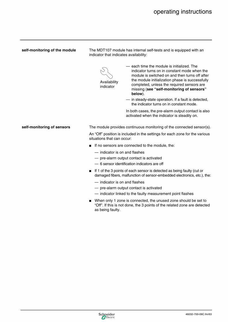
self-monitoring of the module The MDT107 module has internal self-tests and is equipped with an indicator that indicates availability:
Availability indicator
— each time the module is initialized. The indicator turns on in constant mode when the module is switched on and then turns off after the module initialization phase is successfully completed, unless the required sensors are missing (see “self-monitoring of sensors” below).
— in steady-state operation. If a fault is detected, the indicator turns on in constant mode.
In both cases, the pre-alarm output contact is also activated when the indicator is steadily on.
self-monitoring of sensors The module provides continuous monitoring of the connected sensor(s).
An “Off” position is included in the settings for each zone for the various situations that can occur:
■ If no sensors are connected to the module, the:
— indicator is on and flashes
— pre-alarm output contact is activated
— 6 sensor identification indicators are off
■ If 1 of the 3 points of each sensor is detected as being faulty (cut or damaged fibers, malfunction of sensor-embedded electronics, etc.), the:
— indicator is on and flashes
— pre-alarm output contact is activated
— indicator linked to the faulty measurement point flashes
■ When only 1 zone is connected, the unused zone should be set to “Off”. If this is not done, the 3 points of the related zone are detected as being faulty.
46032-700-09C.fm/63
0operating instructions
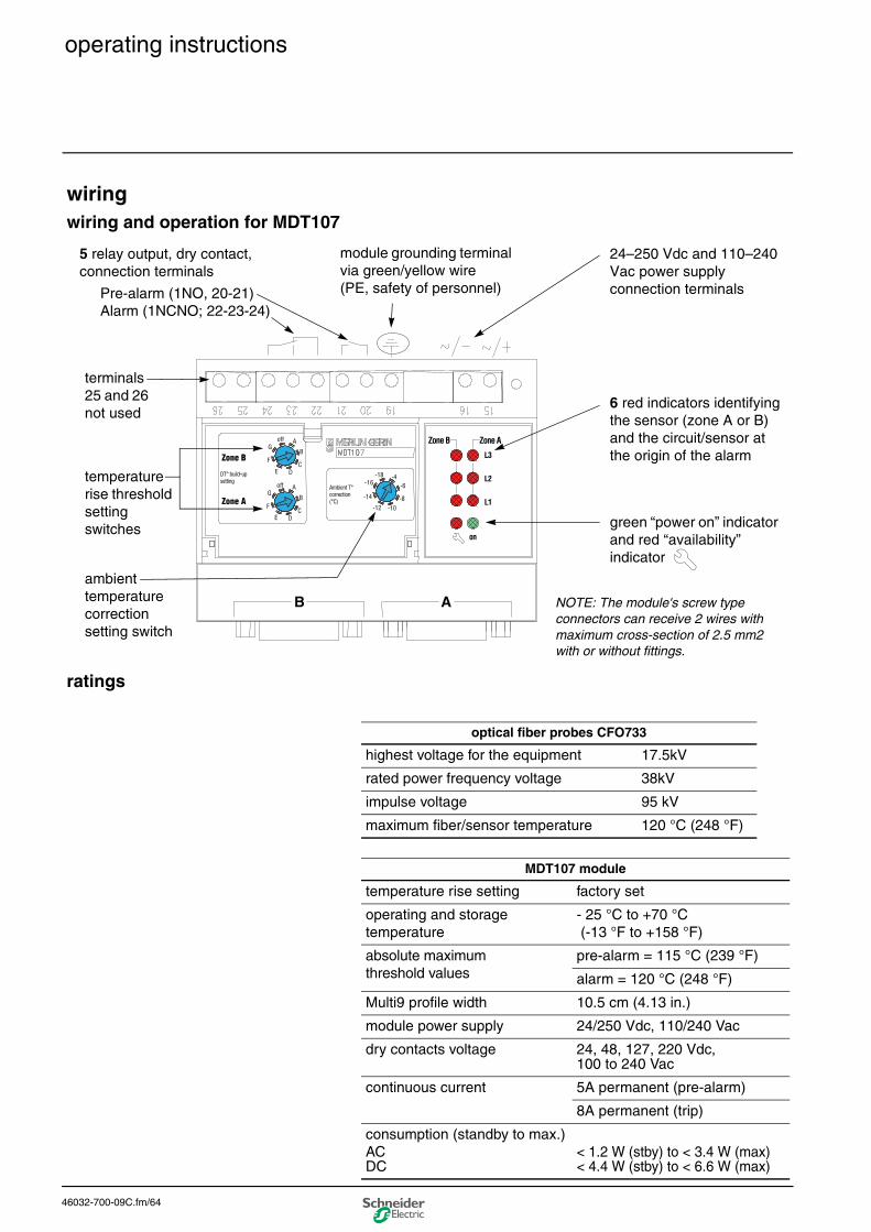
wiringwiring and operation for MDT107
ratings
7
offG
F
EC
B
A
D
offG
F
EC
B
A
D
Zone B
Zone A
DT° build-upsetting
-18-16
-14
-12-8
-6-4
-10
Ambient T°correction(°C)
Zone B Zone A
L3
L1
L2
on
AB
terminals 25 and 26 not used
5 relay output, dry contact, connection terminals
Pre-alarm (1NO, 20-21) Alarm (1NCNO; 22-23-24)
24–250 Vdc and 110–240 Vac power supply connection terminals
6 red indicators identifying the sensor (zone A or B) and the circuit/sensor at the origin of the alarm
green “power on” indicator and red “availability” indicator
ambient temperature correction setting switch
module grounding terminal via green/yellow wire (PE, safety of personnel)
temperature rise threshold setting switches
NOTE: The module's screw type connectors can receive 2 wires with maximum cross-section of 2.5 mm2 with or without fittings.
optical fiber probes CFO733
highest voltage for the equipment 17.5kV
rated power frequency voltage 38kV
impulse voltage 95 kV
maximum fiber/sensor temperature 120 °C (248 °F)
MDT107 module
temperature rise setting factory set
operating and storage temperature
- 25 °C to +70 °C (-13 °F to +158 °F)
absolute maximum threshold values
pre-alarm = 115 °C (239 °F)
alarm = 120 °C (248 °F)
Multi9 profile width 10.5 cm (4.13 in.)
module power supply 24/250 Vdc, 110/240 Vac
dry contacts voltage 24, 48, 127, 220 Vdc, 100 to 240 Vac
continuous current 5A permanent (pre-alarm)
8A permanent (trip)
consumption (standby to max.)ACDC
< 1.2 W (stby) to < 3.4 W (max)< 4.4 W (stby) to < 6.6 W (max)
46032-700-09C.fm/64
0operating instructions
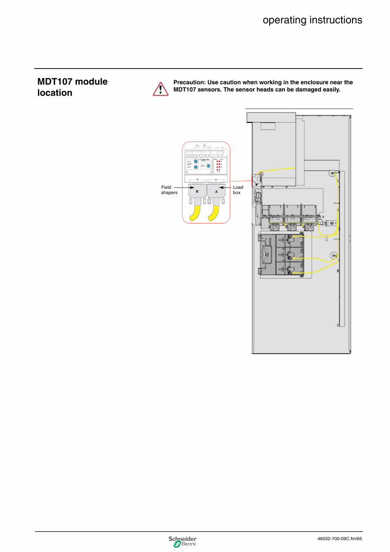
MDT107 module location
Precaution: Use caution when working in the enclosure near the MDT107 sensors. The sensor heads can be damaged easily.
Field shapers
Load box
46032-700-09C.fm/65
0operating instructions
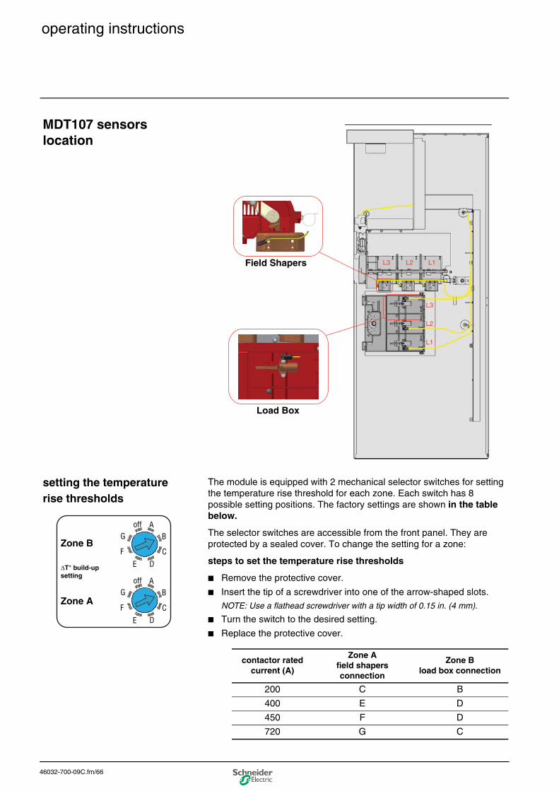
MDT107 sensors location
setting the temperature rise thresholds
The module is equipped with 2 mechanical selector switches for setting the temperature rise threshold for each zone. Each switch has 8 possible setting positions. The factory settings are shown in the table below.
The selector switches are accessible from the front panel. They are protected by a sealed cover. To change the setting for a zone:
steps to set the temperature rise thresholds
■ Remove the protective cover.
■ Insert the tip of a screwdriver into one of the arrow-shaped slots.NOTE: Use a flathead screwdriver with a tip width of 0.15 in. (4 mm).
■ Turn the switch to the desired setting.
■ Replace the protective cover.
Load Box
Field Shapers
Zone B
Zone A
offG
F
E
C
BA
D
offG
F
E
C
BA
D
ΔT° build-upsetting
contactor rated current (A)
Zone Afield shapers connection
Zone Bload box connection
200 C B
400 E D
450 F D
720 G C
46032-700-09C.fm/66
0operating instructions
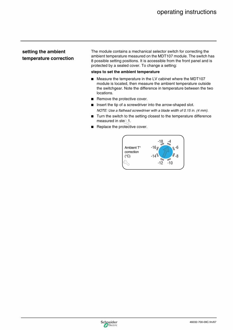
setting the ambient temperature correction
The module contains a mechanical selector switch for correcting the ambient temperature measured on the MDT107 module. The switch has 8 possible setting positions. It is accessible from the front panel and is protected by a sealed cover. To change a setting:
steps to set the ambient temperature
■ Measure the temperature in the LV cabinet where the MDT107 module is located, then measure the ambient temperature outside the switchgear. Note the difference in temperature between the two locations.
■ Remove the protective cover.
■ Insert the tip of a screwdriver into the arrow-shaped slot.NOTE: Use a flathead screwdriver with a blade width of 0.15 in. (4 mm).
■ Turn the switch to the setting closest to the temperature difference measured in step 1.
■ Replace the protective cover.
Ambient T°correction(°C)
-18 -4-6
-8
-10-12
-14
-16
46032-700-09C.fm/67

0operating instructions
troubleshooting The following troubleshooting chart is provided to help minimize downtime. If the proposed solutions do not correct the problem, please contact the Schneider Electric Service Center.
symptoms faulty devicesprobable causes and
solutions
green indicatoris off
external power supply ensure the power supply is present and connected
insufficient voltage (out of range)
MDT107 module is faulty and must be replaced
red indicator remains on after energization
setting selection switches if indicators L1 to L3 are flashing
incorrect positioning of selector switches (for example, 1or more switches is between 2 positions)
indicators L1 to L3 Zones A and B are off
MDT107 module is faulty and must be replaced
red indicator is flashing
probe connection the probe(s) are not connected, or the associated selector switch is in the "Off" position
probes or sensors faulty probe or sensor that must be replaced
46032-700-09C.fm/68
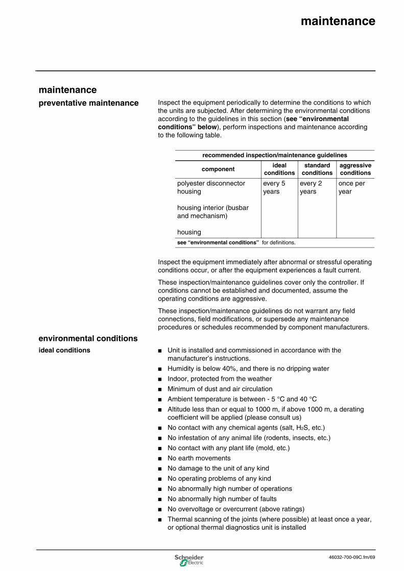
0maintenance
maintenancepreventative maintenance Inspect the equipment periodically to determine the conditions to which
the units are subjected. After determining the environmental conditions according to the guidelines in this section (see “environmental conditions” below), perform inspections and maintenance according to the following table.
recommended inspection/maintenance guidelines
componentideal
conditionsstandard
conditionsaggressive conditions
polyester disconnector housing
housing interior (busbar and mechanism)
housing
every 5 years
every 2 years
once per year
see “environmental conditions” for definitions.
Inspect the equipment immediately after abnormal or stressful operating conditions occur, or after the equipment experiences a fault current.
These inspection/maintenance guidelines cover only the controller. If conditions cannot be established and documented, assume the operating conditions are aggressive.
These inspection/maintenance guidelines do not warrant any field connections, field modifications, or supersede any maintenance procedures or schedules recommended by component manufacturers.
environmental conditionsideal conditions ■ Unit is installed and commissioned in accordance with the
manufacturer’s instructions.
■ Humidity is below 40%, and there is no dripping water
■ Indoor, protected from the weather
■ Minimum of dust and air circulation
■ Ambient temperature is between - 5 °C and 40 °C
■ Altitude less than or equal to 1000 m, if above 1000 m, a derating coefficient will be applied (please consult us)
■ No contact with any chemical agents (salt, H2S, etc.)
■ No infestation of any animal life (rodents, insects, etc.)
■ No contact with any plant life (mold, etc.)
■ No earth movements
■ No damage to the unit of any kind
■ No operating problems of any kind
■ No abnormally high number of operations
■ No abnormally high number of faults
■ No overvoltage or overcurrent (above ratings)
■ Thermal scanning of the joints (where possible) at least once a year, or optional thermal diagnostics unit is installed
46032-700-09C.fm/69

0maintenance
standard conditions Same as "ideal conditions" with the following exceptions:
■ Humidity below 60%
■ The unit must not be subjected to regular extremes of temperatures greater than 40 °C or less than - 30 °C
■ No regular thick covering of leaves or other debris
aggressive conditions Any environmental conditions that have:
■ Humidity above 60%
■ Unit subjected to temperatures greater than 40 °C or less than - 30 °C
46032-700-09C.fm/70
0maintenance
inspecting the equipment
This product is warranted per “Square D Conditions of Sale”, see Schneider Electric document 0100PL0041, and has been tested under ideal laboratory conditions to the values listed below:
■ 1000 mechanical no load operations
■ 3 fuse fault transfer current operations (see IEC 62271-105C for application)
Motorpact™ has been designed and tested to IEC 60470 and related IEC standards. The mechanical life of the disconnector is 5000 operations.
To verify the contact life of the contactor, see Schneider Electric bulletin 46032-700-02, Motorpact™ 200/400/450 A Vacuum Contactors.
To ensure the controller is properly maintained, perform at least the following inspection procedures:
Busbar connections: De-energize the primary and secondary circuits. Perform a standard hi-pot test to measure busbar insulation integrity (see "hi-pot dielectric test" in Schneider Electric bulletin 46032-700-08_, Motorpact IEC Installation Guide).
Inspect the connections for symptoms that indicate overheating or weakened insulation. Remove dust from the surfaces of the busbars, connections, supports, and enclosures. Wipe clean with a solvent such as denatured alcohol. Vacuum the equipment. Do not use compressed air to blow dust from the surfaces inside the controller.
Maintain the instruments, relays, and other devices according to the specific instructions supplied. Inspect the devices and their contacts for dust or dirt; wipe clean as necessary. The maintenance schedule for individual devices such as meters and relays should be based upon recommendations contained in the individual instruction guide for each device. Coordinate the various schedules with the overall maintenance program.
Inspect control wiring connections for tightness and damage.
Manually operate mechanical moving parts such as switch assemblies, interlocks, and doors.
Make sure all busbar areas are well ventilated. Inspect grille work and air passages on controllers to make sure they are free from obstruction and dirt accumulation.
Verify all tools and/or hardware have been removed from the MV compartment.
Replace all devices, doors, and covers with their original mounting hardware.
All operations described hereafter must be carried out in compliance with the safety standards in force, under the responsibility of a competent person.
46032-700-09C.fm/71

0
46032-700-09C.fm/72
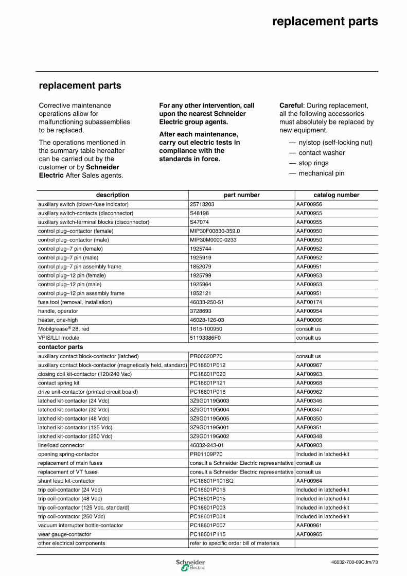
0replacement parts
replacement parts
Corrective maintenance operations allow for malfunctioning subassemblies to be replaced.
The operations mentioned in the summary table hereafter can be carried out by the customer or by Schneider Electric After Sales agents.
For any other intervention, call upon the nearest Schneider Electric group agents.
After each maintenance, carry out electric tests in compliance with the standards in force.
Careful: During replacement, all the following accessories must absolutely be replaced by new equipment.
— nylstop (self-locking nut)
— contact washer
— stop rings
— mechanical pin
description part number catalog numberauxiliary switch (blown-fuse indicator) 25713203 AAF00956
auxiliary switch-contacts (disconnector) S48198 AAF00955
auxiliary switch-terminal blocks (disconnector) S47074 AAF00955
control plug–contactor (female) MIP30F00830-359.0 AAF00950
control plug–contactor (male) MIP30M0000-0233 AAF00950
control plug–7 pin (female) 1925744 AAF00952
control plug–7 pin (male) 1925919 AAF00952
control plug–7 pin assembly frame 1852079 AAF00951
control plug–12 pin (female) 1925799 AAF00953
control plug–12 pin (male) 1925964 AAF00953
control plug–12 pin assembly frame 1852121 AAF00951
fuse tool (removal, installation) 46033-250-51 AAF00174
handle, operator 3728693 AAF00954
heater, one-high 46028-126-03 AAF00006
Mobilgrease® 28, red 1615-100950 consult us
VPIS/LLI module 51193386F0 consult us
contactor partsauxiliary contact block-contactor (latched) PR00620P70 consult us
auxiliary contact block-contactor (magnetically held, standard) PC18601P012 AAF00967
closing coil kit-contactor (120/240 Vac) PC18601P020 AAF00963
contact spring kit PC18601P121 AAF00968
drive unit-contactor (printed circuit board) PC18601P016 AAF00962
latched kit-contactor (24 Vdc) 3Z9G0119G003 AAF00346
latched kit-contactor (32 Vdc) 3Z9G0119G004 AAF00347
latched kit-contactor (48 Vdc) 3Z9G0119G005 AAF00350
latched kit-contactor (125 Vdc) 3Z9G0119G001 AAF00351
latched kit-contactor (250 Vdc) 3Z9G0119G002 AAF00348
line/load connector 46032-243-01 AAF00903
opening spring-contactor PR01109P70 Included in latched-kit
replacement of main fuses consult a Schneider Electric representative consult us
replacement of VT fuses consult a Schneider Electric representative consult us
shunt lead kit-contactor PC18601P101SQ AAF00964
trip coil-contactor (24 Vdc) PC18601P015 Included in latched-kit
trip coil-contactor (48 Vdc) PC18601P015 Included in latched-kit
trip coil-contactor (125 Vdc, standard) PC18601P003 Included in latched-kit
trip coil-contactor (250 Vdc) PC18601P004 Included in latched-kit
vacuum interrupter bottle-contactor PC18601P007 AAF00961
wear gauge-contactor PC18601P115 AAF00965
other electrical components refer to specific order bill of materials
46032-700-09C.fm/73

0
46032-700-09C.fm/74

0troubleshooting
troubleshooting
■ MV compartment door cannot be opened
Check that the disconnector is in the OPEN/earthed position.
Check that the disconnector access port is CLOSED.
■ Disconnector cannot be operated
Check that the MV compartment door is CLOSED and the handle latched.
Check that the contactor is in the OPEN position.
Check that the earthing switch (if supplied) is OPEN and the access port is CLOSED.
■ Disconnector access port cannot be CLOSED
Check that the disconnector is fully OPEN or earthed.
Check that the key interlock keys (if supplied) are in the proper position.
■ Disconnector access port cannot be OPENED
Check that the disconnector is fully OPEN or earthed.
Check that the key interlock keys (if supplied) are in the proper position.
■ Cable earthing switch cannot be operated
Check that the contactor is in the OPEN position.
Check that the disconnector is in the OPEN/earthed position.
Check that the MV compartment door is CLOSED and the handle is latched.
Check that the disconnector operating access port is OPEN.
■ Contactor will not CLOSE electrically
Check that the disconnector is CLOSED.
Check that the disconnector access port is CLOSED.
Check the control fuses.
Check the closing coil circuit.
Check for loose terminal connections.
Check for a loose plug connection in the LV cabinet.
Check the electrical interlocks. see "equipment drawings" provided with each lineup.
Check the interlock linkage to the contactor.
■ Latched contactor will not OPEN electrically
Check the control fuses.
Check the trip coil circuit.
Check for loose terminal connections.
Check for loose plug connections in the LV cabinet.
Check the electrical interlocks. see "equipment drawings" provided with each lineup.
■ Voltage presence indicator does not illuminate
Test for voltage on 2 of the test ports on the indicating box. Verify the MV voltage is truly present.
All operations described hereafter must be carried out in compliance with the safety standards in force, under the responsibility of a competent person.
46032-700-09C.fm/75

0
46032-700-09C.fm/76
0glossary
auxiliary contacts Sets of contacts mechanically operated by the disconnector or the contactor.
auxiliary section An enclosure section that contains either low voltage or medium voltage components that require a different mounting than a typical controller section.
busbar compartment The compartment isolating the through or main busbars in a Motorpact™ switchboard lineup.
cable earthing switch A sliding 2-position device (CLOSED position earthed). Designed to discharge the capacitance to earth up to a 5 kA fault.
capacitive divider A capacitor attached to the phase busbar that is used to send a reduced voltage signal to a neon light for voltage presence indication.
contactor The mobile vacuum interrupting device used for establishing and interrupting the medium voltage power in the circuit.
controller A device or group of devices used to govern the power delivered to the apparatus of which it is connected.
control power transformer (CPT) A transformer that reduces medium voltage to low voltage for control circuit use.
current transformer (CT) An instrument transformer intended to have its primary winding connected in series with the conductor carrying the current to be measured or controlled.
disconnector A rotating, 2-position switch that is used to connect the main power source in the closed position and to connect to the equipment earth in the open position.
full voltage starter A motor starter which connects the line voltage across the motor terminals in one step.
fuse, medium voltage A medium voltage fuse capable of interrupting all currents from the rated breaking capacity to the minimum breaking current I3.
fuse ferrule A cylindrical fuse terminal at the end of a cartridge fuse.
fuseholder An assembly of insulated fuse tubes that house the primary contacts of the medium voltage fuse connection for the CPT and VT fuses.
insulator A device intended to insulate and give rigid support to busbars throughout the equipment.
interlocks A device actuated by the operation of some other device to govern succeeding operations. The interlocks are classified into three main divisions: mechanical, electrical, and key interlocks.
46032-700-09C.fm/77
0glossary
internal arc tunnel An air chamber or compartment attached to the roof of the switchboard lineup. This compartment is designed for containing or distributing the gases should an internal arc event occur.
internal arc withstand A description for the added features of the enclosure which help in the withstand or containment of a gas discharge should an internal arc event occur.
low power current transformer (LPCT)
A device that transforms a medium voltage circuit current into a proportional low voltage signal.
medium voltage compartment A switchboard compartment which houses any medium voltage devices.
power factor correction capacitor (PFCC)
A device that counteracts the undesirable effects of electric loads which create a power factor less than 1.
shipping section Any combination of Motorpact™ units shipped together.
starter The combination of all the switching means necessary to start and stop a motor with suitable overload protection.
stress cone Pre-manufactured insulated cable termination recommended for all incoming/outgoing and load connections.
surge arrester A device intended to protect equipment from electrical overvoltage.
voltage transformer (VT) An instrument transformer intended to have its primary winding connected in shunt with a power supply circuit for measuring the voltage.
voltage presence indication system (VPIS)
The VPIS is a light module mounted on the front of the equipment that gives an indication when voltage is present on the MV cables. Energy is provided from a capacitive divider (see definition for capacitive divider).
wiring harness Pre-manufactured wiring bundles or connections.
46032-700-09C.fm/78

0
0
46032-700-09C.fm/79

0
46032-700-09C.fm/80

0
46032-700-09C.fm/81
4603
2-70
0-09
C ©
200
4–20
08 S
chne
ider
Ele
ctric
All
right
s re
serv
ed.
Schneider Electric Industries SASAddress:330 Weakley RoadSmyrna, TN 37167, USA1-888-778-2377
www.schneider-electric.com
46032-700-09C 02/2008
The Schneider group service centers are at your service for:
• engineering and technical assistance• commissioning• training• preventive and corrective maintenance• adaptation• spare parts
Contact your sales representative who will putyou in touch with your nearest Schneider groupservice center or call us on 33 (0)4 76 57 60 60(Grenoble, France).
As standards, specifications, and designs change from time to time, please ask for confirmation of the information given in this publication.
This document has been printed on ecological paper.