Embed Size (px)
Citation preview

Motors | Automation | Energy | Transmission & Distribution | Coatings
RS485 ModuleMódulo RS485
CFW100
Installation, Configuration and Operation Guide Guía de Instalación, Configuración y Operación Guia de Instalação, Configuração e Operação
English / Español / Português


Summary / Índice
En
glis
hE
spañ
ol
Po
rtug
uês
Summary
1 SAFETY INFORMATION ................................51.1 SAFETY WARNINGS .......................................51.2 PRELIMINARY RECOMMENDATIONS ..........5
2 GENERAL INFORMATION ............................5
3 PACKAGE CONTENT ...................................5
4 INSTALLATION OF THE ACCESSORY ........6
5 CONFIGURATIONS .......................................6
APPENDIX A – FIGURES ................................16
Índice
1 INFORMACIONES DE SEGURIDAD ............91.1 AVISOS DE SEGURIDAD ................................91.2 PRELIMINARY RECOMMENDATIONS ..........9
2 INFORMACIONES GENERALES ..................9
3 CONTENIDO DEL EMBALAJE ....................9
4 INSTALACIÓN DEL ACCESORIO...............10
5 CONFIGURACIONES ..................................10
ANEXO A – FIGURAS ......................................16
Índice
1 INFORMAÇÕES DE SEGURANÇA .............131.1 AVISOS DE SEGURANÇA .............................131.2 RECOMENDAÇÕES PRELIMINARES .........13
2 INFORMAÇÕES GERAIS ............................13
3 CONTEÚDO DA EMBALAGEM ..................13
4 INSTALAÇÃO DO ACESSÓRIO ..................14
5 CONFIGURAÇÕES ......................................14
ANEXO A – FIGURAS ......................................16


RS485 Module
CFW100 | 5
En
glis
h
1 SAFETY INFORMATION
1.1 SAFETY WARNINGS
NOTE! � Only use the RS485 module (CFW100-
CRS485) on WEG CFW100 series inverters. � It is recommended reading the CFW100
User’s Manual before installing or operating this accessory.
� The content of this guide provides important information for the full understanding and proper operation of this module.
1.2 PRELIMINARY RECOMMENDATIONS
ATTENTION! � Always disconnect the general power supply
before connecting or disconnecting the accessories of the CFW100 frequency inverter.
� Wait for at least ten minutes for the full discharge of the inverter.
2 GENERAL INFORMATION
This guide provides directions for the installation, configuration and operation of the RS485 module (CFW100-CRS485).
3 PACKAGE CONTENT
Upon receiving the product, check if the package contains: � Accessory in anti-static package. � Installation, configuration and operation guide.

RS485 Module
6 | CFW100
En
glish
4 INSTALLATION OF THE ACCESSORY
The CFW100-CRS485 is easily connected to the CFW100 frequency inverter by means of the plug-and-play concept. The procedures below must be observed for the proper installation and start-up:
1. With the inverter de-energized, remove the front cover of the inverter shown in figure A.1 (a).
2. Fit the accessory to be installed as shown in figure A.1 (b). 3. Power up the inverter.
5 CONFIGURATIONS
The RS485 interface connections must be done on the connector as per table 1.
Table 1: Connector signals of the RS485 interface
Connector Description
6 RS485 - B RS485 (Terminal B)
7 RS485 - A RS485 (Terminal A)
8 0 V Reference 0 V
9 PE Grounding connection
10 - ---------------------
The location of the DIP switch to select the RS485 network termination can be better viewed in figure A.2 and it must be configure as per table 2.

RS485 Module
CFW100 | 7
En
glis
h
Table 2: Configuration of the switches to configure the RS485
Comunication Switch Switch Setting Option
SR S1(*)
S1.1 = OFF and S1.2 = OFF
RS485 Termination off
S1.1 = ON and S1.2 = ON
RS485 Termination
on (**)
(*) Any other combination of the switches is not allowed.(**) It is recommended to use this termination with cables longer than 3 m.
NOTE! � The mini USB connector (see f igure
A.2) is used for communication with the CFW100-KHMIR kit only.
� The use of the mini USB connector for other connections is not permitted.
NOTE!The use of 38400-bps serial baud rate (P310=2) with the vector control mode VVW (P202=5) is not allowed. This condition activates the Config state (Conf) so as to indicate parameterization incompatibility. For further details, refer to chapter 5 of the CFW100 programming manual.

RS485 Module
8 | CFW100
En
glish

Módulo RS485
CFW100 | 9
Esp
año
l
1 INFORMACIONES DE SEGURIDAD
1.1 AVISOS DE SEGURIDAD
¡NOTA! � Solamente uti l ice el módulo RS485
(CFW100-CRS485) en los convertidores WEG serie CFW100.
� Se recomienda la lectura del manual del usuario del CFW100 antes de instalar u operar este accesorio.
� El conten ido de esta gu ía provee informaciones importantes para el correcto entendimiento y el buen funcionamiento de este módulo.
1.2 PRELIMINARY RECOMMENDATIONS
¡ATENCIÓN! � Siempre desconecte la alimentación
general antes de conectar o desconectar los accesorios del convertidor de frecuencia CFW100.
� Aguarde por lo menos 10 minutos para garantizar la desenergización completa del convertidor.
2 INFORMACIONES GENERALES
Esta guía orienta en la instalación, configuración y operación del módulo RS485 (CFW100-CRS485).
3 CONTENIDO DEL EMBALAJE
Al recibir el producto, verificar si el embalaje contiene: � Accesorio en embalaje antiestático. � Guía de instalación, configuración y operación.

Módulo RS485
10 | CFW100
Esp
año
l
4 INSTALACIÓN DEL ACCESORIO
El CFW100-CRS485 es fácilmente conectado al conver tidor de frecuencia CFW100 uti l izando el concepto “plug-and-play”. Los procedimientos de abajo debe ser seguidos para la correcta instalación y puesta en funcionamiento:
1. Con el convertidor desenergizado, retire la tapa frontal del mismo, figura A.1 (a).
2. Encaje el accesorio a ser instalado conforme es indicado en la figura A.1 (b).
3. Energice el convertidor.
5 CONFIGURACIONES
Las conexiones de la interfaz RS485 deben ser hechas en el conector, conforme la tabla 1.
Tabla 1: Señales del conector de la interfaz RS485
Conector Descripción
6 RS485 - B RS485 (Terminal B)
7 RS485 - A RS485 (Terminal A)
8 0 V Referencia 0 V
9 PE Conexión de puesta a tierra
10 - ---------------------
A localização da DIP-switch para seleção da terminação da rede RS485 pode ser melhor visualizada na figura A.2 e deve ser configurada conforme tabela 2.

Módulo RS485
CFW100 | 11
Esp
año
l
Tabla 2: Configuraciones de las llaves para configuración de la RS485
Comunicación Llave Ajuste de las Llaves Opción
RS 485 S1(*)
S1.1 = OFF y S1.2 = OFF
Terminación RS485 apagada
S1.1 = ON y S1.2 = ON
Terminación RS485
encendida (**)
(*) Cualquier otra combinación de las llaves no está permitida.(**) Se recomienda el uso de esta terminación con el uso de cables mayores de 3 m.
¡NOTA! � El conector mini USB (ver figura A.2) es
utilizado solamente para comunicación con el kit CFW100-KHMIR.
� No está permitida la uti l ización del conector mini USB para otras conexiones.
¡NOTA!No está permitida la utilización de la tasa de comunicación serial en 38400 bps (P310=2) junto al modo de control vectorial V V W (P202=5). Esta condición activa el estado “Config” (Conf) para indicar incompatibilidad de parametrización. Por más detalles consulte el capítulo 5 del manual de programación del CFW100.

Módulo RS485
12 | CFW100
Esp
año
l

Módulo RS485
CFW100 | 13
Po
rtug
uês
1 INFORMAÇÕES DE SEGURANÇA
1.1 AVISOS DE SEGURANÇA
NOTA! � Somente ut i l i za r o módulo RS485
(CFW100-CRS485) nos inversores WEG série CFW100.
� Recomenda-se a leitura do manual do usuário do CFW100 antes de instalar ou operar esse acessório.
� O conteúdo deste guia fornece informações importantes para o correto entendimento e bom funcionamento deste módulo.
1.2 RECOMENDAÇÕES PRELIMINARES
ATENÇÃO! � Sempre desconecte a alimentação geral
antes de conectar ou desconectar os acessórios do inversor de frequência CFW100.
� Aguarde pelo menos 10 minutos para garantir a desenergização completa do inversor.
2 INFORMAÇÕES GERAIS
Este guia orienta na instalação, configuração e operação do módulo RS485 (CFW100-CRS485).
3 CONTEÚDO DA EMBALAGEM
Ao receber o produto, verificar se a embalagem contém: � Acessório em embalagem anti-estática. � Guia de instalação, configuração e operação.
Módulo RS485
14 | CFW100
Po
rtuguês
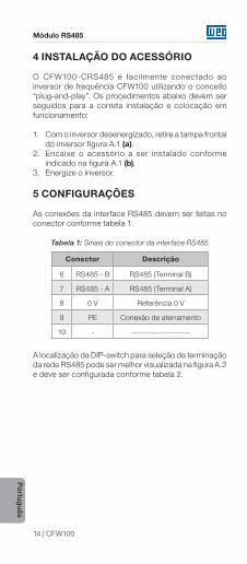
4 INSTALAÇÃO DO ACESSÓRIO
O CFW100-CRS485 é faci lmente conectado ao inversor de frequência CFW100 utilizando o conceito “plug-and-play”. Os procedimentos abaixo devem ser seguidos para a correta instalação e colocação em funcionamento:
1. Com o inversor desenergizado, retire a tampa frontal do inversor figura A.1 (a).
2. Encaixe o acessório a ser instalado conforme indicado na figura A.1 (b).
3. Energize o inversor.
5 CONFIGURAÇÕES
As conexões da interface RS485 devem ser feitas no conector conforme tabela 1.
Tabela 1: Sinais do conector da interface RS485
Conector Descrição
6 RS485 - B RS485 (Terminal B)
7 RS485 - A RS485 (Terminal A)
8 0 V Referência 0 V
9 PE Conexão de aterramento
10 - ---------------------
A localização da DIP-switch para seleção da terminação da rede RS485 pode ser melhor visualizada na figura A.2 e deve ser configurada conforme tabela 2.

Módulo RS485
CFW100 | 15
Po
rtug
uês
Tabela 2: Configurações das chaves para configuração da RS485
Comunicação Chave Ajuste das Chaves Opção
RS 485 S1(*)
S1.1 = OFF e S1.2 = OFF
Terminação RS485 desligada
S1.1 = ON e S1.2 = ON
Terminação
RS485 ligada (**)
(*) Qualquer outra combinação das chaves não é permitida.(**) Recomenda-se o uso desta terminação com o uso de cabos maiores de 3 m.
NOTA! � O conector mini USB (ver figura A.2) é
utilizado somente para comunicação com o kit CFW100-KHMIR.
� Não é permitida a utilização do conector mini USB para outras conexões.
NOTA!Não é permitida a utilização da taxa de comunicação serial em 38400 bps (P310=2) juntamente com o modo de contro le vetor ial V V W (P202=5). Esta condição ativa o estado Config (Conf) para indicar incompatibilidade de parametrização. Para mais detalhes consulte o capítulo 5 do manual de programação do CFW100.

Appendix A - Anexo A
16 | CFW100
APPENDIX A – FIGURESANEXO A – FIGURASANEXO A – FIGURAS
(a) Removal of front cover (a) Remoción de la tapa frontal (a) Remoção da tampa frontal
(b) Accessory connection(b) Conexión del accesorio(b) Conexão de acessório
Figure A.1 (a) to (b): Installation of accessory
Figura A.1 (a) a (b): Instalación de accesorio
Figura A.1 (a) a (b): Instalação de acessório

Appendix A - Anexo A
CFW100 | 17
DIP-switch
1ON
2
Conector interface RS485
Mini USB
32.3 [1.27]
53 [2.09]
21.8
[0.8
6]
Figure A.2: CFW100-CRS485 dimensions in mm [in] and connectors location
Figura A.2: Dimensiones del CFW100-CRS485 en mm [in] y localización de los conectadores
Figura A.2: Dimensões do CFW100-CRS485 em mm [in] e localização dos conectores

ANOTAÇÕES DO USUÁRIO


Doc
umen
t: 10
001
4331
10 /
01
WEG Drives & Controls - Automação LTDA.Jaraguá do Sul - SC - Brazil Phone 55 (47) 3276-4000 - Fax 55 (47) 3276-4020São Paulo - SP - Brazil Phone 55 (11) 5053-2300 - Fax 55 (11) [email protected] 11880376