Embed Size (px)
Citation preview
IB-21B001
EMERALD SERIES APRIL 2008
MOTORS & DRIVES
INSTRUCTION BOOK
INDUSTRIAL INDEXING SYSTEMS, Inc.
Revision - A
Proprietary information of Industrial Indexing Systems, Inc. furnished for customer use only. No other uses are authorized without the prior written permission of
Industrial Indexing Systems, Inc.
ER-6042
ERRATA SHEET, IB-21B001 REV. 0 OCTOBER 2009
INDUSTRIAL INDEXING SYSTEMS, Inc. 626 Fishers Run
Tel: (585) 924-9181 Victor, New York 14564 Fax: (585) 924-2169
Date Rev. ECN No. DR CHK CHK
9/10/08 0 ECN-08-168 (See Note 1) KY
11/18/08 A ECN-08-244 (See Note 2) KY
4/6/09 B ECN-07-064 (See Note 3) KY AW
10/19/09 C ECN-09-097 (See Note 4) KY
Notes: 1) Table of Contents page iv, List of Illustrations page vi, Introduction page vii, Section 1 page 1-1,
Section 4 page 4-1, Appendix B dated September 2008, supersedes Table of Contents page iv, List of Illustrations page vi, Introduction page vii, Section 1 page 1-1, Section 4 page 4-1, Appendix B dated April 2008.
2) Appendix B, pages B-3, B-6 and B-7 dated November 2008, supersede Appendix B, pages B-3, B-6
and B-7 dated September 2008. 3) Pages 5-1, 6-34, 6-59, 7-3. 7-4 and 7-5 dated April 2009, supersede pages 5-1, 6-34, 6-59, 7-3. 7-4
and 7-5 dated April 2008. 4) Appendix A, dated October 2009, supersedes Appendix A, dated April 2008.
Proprietary information of Industrial Indexing Systems, Inc. furnished for customer use only. No other uses are authorized without the prior written permission of
Industrial Indexing Systems, Inc.
INDUSTRIAL INDEXING SYSTEMS, Inc. IB-21B001 EMERALD SERIES MOTORS & DRIVES USER’S GUIDE
APRIL 2008 TABLE OF CONTENTS ii
TABLE OF CONTENTS
List of Illustrations................................................................................................................................................. v Introduction..........................................................................................................................................................vii
SECTION 1 - INSTALLATION AND SAFETY 1.1 Installing the Emerald Servo Drive ......................................................................................1 - 1 1.1.1 Regulatory Agency Installations.............................................................................1 - 1 1.1.2 Choosing an Electrical Enclosure ..........................................................................1 - 2 1.1.3 Emerald Servo Drive and Regen Resistor Mounting ............................................1 - 2 1.1.4 Final Checks Prior to Applying Power ...................................................................1 - 2
1.2 Powering Up an Emerald Servo Drive for the First Time....................................................1 - 4 1.2.1 Steps to First Time Power Up ................................................................................1 - 4
1.3 Building an Electrical Enclosure for Agency Approval ........................................................1 - 5 1.3.1 Building an Electrical Enclosure Force ..................................................................1 - 5
SECTION 2 - OVERVIEW 2.1 Identifying Emerald Drives...................................................................................................2 - 1
2.2 Identifying Emerald Motors ..................................................................................................2 - 2 SECTION 3 - DESCRIPTION 3.1 Components.........................................................................................................................3 - 2 3.1.1 Status Indicators.....................................................................................................3 - 2 3.1.2 Connections............................................................................................................3 - 2 SECTION 4 - SPECIFICATIONS 4.1 Driver Specifications ............................................................................................................4 - 1 4.1.1 Motor Output...........................................................................................................4 - 1 4.1.2 Main Bus Power Supply .........................................................................................4 - 2 4.1.3 Control Power Supply.............................................................................................4 - 3 4.1.4 Control Performance ..............................................................................................4 - 3 4.1.5 Environment............................................................................................................4 - 4 4.1.6 Sercos Interface .....................................................................................................4 - 4 4.1.7 Serial I/O Interface..................................................................................................4 - 4 4.1.8 Communication Ports.............................................................................................4 - 4 4.1.9 Motor/Auxiliary Encoder Inputs ..............................................................................4 - 5 4.1.10 Probe Inputs ...........................................................................................................4 - 5 4.1.11 Analog I/O Signals..................................................................................................4 - 5 4.1.12 Protection................................................................................................................4 - 5
4.2 Motor Specifications.............................................................................................................4 - 6 4.2.1 General ...................................................................................................................4 - 6 4.2.2 Feedback Device....................................................................................................4 - 6 4.2.3 Other .......................................................................................................................4 - 6
INDUSTRIAL INDEXING SYSTEMS, Inc. IB-21B001 EMERALD SERIES MOTORS & DRIVES USER’S GUIDE
APRIL 2008 TABLE OF CONTENTS iii
SECTION 5 - CONNECTIONS / WIRING 5.1 Control Power Wiring...........................................................................................................5 - 1
5.2 Main Bus Power Supply Wiring ...........................................................................................5 - 2 5.2.1 Supplemental Circuit Protection.............................................................................5 - 2 5.2.2 Contactor ................................................................................................................5 - 3 5.2.3 Wire Sizes...............................................................................................................5 - 4 5.2.4 Transformers ..........................................................................................................5 - 5 5.2.5 Wiring Practices and Grounding ............................................................................5 - 6
5.3 Driver Regeneration Capacities...........................................................................................5 - 6 5.3.1 Selection of an External Regeneration Resistor....................................................5 - 7 5.3.2 Standard Regeneration Resistor Packages ..........................................................5 - 9 5.4 DC Link Reactor.................................................................................................................5 - 18 5.5 Sercos TX/RX Connections...............................................................................................5 - 18 5.6 Touchscreen & PC Connections .......................................................................................5 - 19 SECTION 6 - CONFIGURATION & PROGRAMMING 6.1 Configuration Switch ............................................................................................................6 - 1 6.2 Identification Numbers .........................................................................................................6 - 2 6.2.1 IDN List in Numerical Order ...................................................................................6 - 2 6.2.2 IDN List By Function...............................................................................................6 - 6 6.2.3 IDN Description - Standard Parameters..............................................................6 - 11
SECTION 7 - FAULT CODES / STATUS 7.1 Status ...................................................................................................................................7 - 1
7.2 Fault Codes..........................................................................................................................7 - 2
7.3 I/O Can Network Status Display..........................................................................................7 - 6
7.4 Sercos Receiver Error LED .................................................................................................7 - 6 APPENDIX A - MOTORS, DRIVES, CABLES AND ACCESSORIES A.1 Motors, Drives and Cables ................................................................................................. A - 1 A.2 Cables and Accessories Drawings..................................................................................... A - 1
INDUSTRIAL INDEXING SYSTEMS, Inc. IB-21B001 EMERALD SERIES MOTORS & DRIVES USER’S GUIDE
SEPTEMBER 2008 TABLE OF CONTENTS iv
APPENDIX B - ESD-I/O16 & ESD-IO16-DC I/O EXPANDER B.1 Overview.............................................................................................................................. B - 1
B.2 Description .......................................................................................................................... B - 1
B.3 Specifications ...................................................................................................................... B - 1 B.3.1 Power Requirement............................................................................................... B - 1 B.3.2 Environment........................................................................................................... B - 1 B.3.3 Size ........................................................................................................................ B - 2 B.3.3.1 ESD-I/O16 Size........................................................................................ B - 2 B.3.3.2 ESD-IO16-DC Size.................................................................................. B - 3 B.3.4 Digital Inputs/Outputs ............................................................................................ B - 4 B.3.4.1 ESD-I/O16................................................................................................ B - 4 B.3.4.2 ESD-IO16-DC .......................................................................................... B - 4
B.4 Wiring .................................................................................................................................. B - 4 B.4.1 Power & Communication Wiring ........................................................................... B - 4 B.4.2 I/O Wiring............................................................................................................... B - 5
B.5 Hardware Configuration, DIP Switch Setting ..................................................................... B - 7
B.6 Status LEDs ........................................................................................................................ B - 7
APPENDIX C - EMC INSTALLATION GUIDELINES FOR EMERALD SERIES
MOTORS AND DRIVERS C.1 Introduction to EMC Guidelines..........................................................................................C - 1
C.2 EMC Requirements.............................................................................................................C - 1
C.3 Control Enclosure................................................................................................................C - 2
C.4 Enclosure Mounting Panel..................................................................................................C - 2
C.5 Power Wiring Shielding and Filtering .................................................................................C - 3 C.5.1 Power Line Filter....................................................................................................C - 4 C.5.2 Driver Output (Motor Armature) Filter ...................................................................C - 4 C.5.3 Shielded Motor Cable............................................................................................C - 4 C.5.4 Regeneration Resistor Wiring Shielding (Option) ................................................C - 5
C.6 Digital Control Signals.........................................................................................................C - 5
INDUSTRIAL INDEXING SYSTEMS, Inc. IB-21B001 EMERALD SERIES MOTORS & DRIVES USER’S GUIDE
APRIL 2008 LIST OF ILLUSTRATIONS v
LIST OF ILLUSTRATIONS SECTION 1 - INSTALLATION AND SAFETY SECTION 2 - OVERVIEW SECTION 3 - DESCRIPTION
Figure 3.1 Emerald Layout ......................................................................................................3 - 1 SECTION 4 - SPECIFICATIONS SECTION 5 - CONNECTIONS / WIRING Figure 5.1 Wiring Interconnect ................................................................................................5 - 1 Figure 5.2 Time ........................................................................................................................5 - 7 Figure 5.3 Connecting the SERCOS Ring ............................................................................5 - 18 Figure 5.4 Connecting the Emerald to a Touchscreen and PC............................................5 - 19
Table 5.1 Recommended Circuit Protector............................................................................5 - 2 Table 5.2 Recommended Contactors, 24 VDC Coil..............................................................5 - 3 Table 5.3 Recommended Bus Power Wire Size ...................................................................5 - 4 Table 5.4 Energy Absorption Capabilities..............................................................................5 - 6 Table 5.5 Regeneration Resistor Selection Data ..................................................................5 - 8
SECTION 6 - CONFIGURATION & PROGRAMMING Figure 6.1 Configuration Switch Settings ................................................................................6 - 1 Figure 6.2 Velocity Polarity Parameter..................................................................................6 - 22 Figure 6.3 Position Polarity Parameter..................................................................................6 - 24 Figure 6.4 Torque Polarity Parameter ...................................................................................6 - 26 Figure 6.5 Example of Velocity Window................................................................................6 - 39 SECTION 7 - FAULT CODES / STATUS Figure 7.1 System Status (7 Segment Status Display) ..........................................................7 - 1 Table 7.1 Fault Codes ............................................................................................................7 - 2 Table 7.2 Cross Reference of Fault Codes to Class 1 Diagnostics......................................7 - 5 APPENDIX A - MOTORS, DRIVES, CABLES AND ACCESSORIES Figure A.1 Extended Encoder Cable Configuration ............................................................... A - 1
INDUSTRIAL INDEXING SYSTEMS, Inc. IB-21B001 EMERALD SERIES MOTORS & DRIVES USER’S GUIDE
SEPTEMBER 2008 LIST OF ILLUSTRATIONS vi
APPENDIX B - ESD-I/O16 & ESD-IO16-DC I/O EXPANDER
Figure B.1 ESD-I/O16 Layout ................................................................................................. B - 2 Figure B.2 ESD-IO16-DC Layout............................................................................................ B - 3 Figure B.3 ESD-I/O16 Wiring Using TB1................................................................................ B - 5 Figure B.4 ESD-I/O16 Wiring for Modules ............................................................................. B - 5 Figure B.5 ESD-IO16-DC Wiring Using TB1.......................................................................... B - 6 Figure B.6 ESD-IO16-DC Wiring ............................................................................................ B - 6 APPENDIX C - EMC INSTALLATION GUIDELINES FOR EMERALD SERIES
MOTORS AND DRIVERS Figure C.1 Power Wiring Shielding and Filtering....................................................................C - 3 Figure C.2 Regeneration Resistor Wire Shielding..................................................................C - 5
INDUSTRIAL INDEXING SYSTEMS, Inc. IB-21B001 EMERALD SERIES MOTORS & DRIVES USER’S GUIDE
SEPTEMBER 2008 INTRODUCTION vii
INTRODUCTION Thank you for selecting Industrial Indexing Systems’ Emerald Series products. You join many other companies around the world in your choice of these powerful, flexible motion control products. The Emerald Driver can be configured by the user to operate as a Single Axis Driver /Controller combination (CONTROLLER Mode) or as a Slave Device connected to a SERCOS InterfaceTM1 Master controller (SERCOS Mode). The design of the Emerald Drivers combine the latest in all-digital electronic design, SMT circuit board construction and clever engineering to deliver high performance, advanced features and reasonable cost. Compact, high power density motors provide low rotor inertia, making them the logical choice for positioning and indexing applications. Emerald Drivers have a wide array of features, including a powerful embedded high speed 32-bit 150 MHz Digital Signal Processor, high visibility 7-segment LED Status display, Support for Analog and Digital I/0, programmable limit switches, S-curve profiling, fault history log and many more. Dozens of operational parameters can be programmed. Utilizing Emerald’s Windows based PC software tools, allows quick set-up for a full range of diagnostics and PC oscilloscope functions to display speed and current waveforms and most any other diagnostic data the user may need. NRTL Certification The Emerald drive series has been evaluated by TUV SUD AMERICA INC. to the standards of UL508C, CSA C22.2.14 and CE EN61326. Reference materials for the Emerald Series of Motion Control Systems: IB-20B004 EMC-2005 Emerald Multi-Axis Controller HPB Catalog Additional Motor Specifications EDE Emerald Software Development Tools EDrive Diagnostic Tools SMA2000 Servo Mechanical Analysis
1 SERCOS Interface is a trademark of Interest Groups SERCOS
INDUSTRIAL INDEXING SYSTEMS, Inc. IB-21B001 EMERALD SERIES MOTORS & DRIVES USER’S GUIDE
SEPTEMBER 2008 PAGE 1 - 1
SECTION 1 - INSTALLATION AND SAFETY NRTL Certification The Emerald drive series has been evaluated by TUV SUD AMERICA INC. to the standards of UL508C, CSA C22.2.14 and CE EN61326. Definition - Within this document will be the phrase “MAIN BUS POWER SUPPLY”. This
phrase is to define the AC power as 220V AC +/-20% or 440V AC +/-20%, see Section 4.1.2 for further details.
WHEN INSTALLING AN EMERALD SERVO DRIVE FOR THE FIRST TIME OR REPLACING AN EXISTING DRIVE ALWAYS FOLLOW BOTH SECTIONS 1.1.4 AND 1.2.
1.1 INSTALLING THE EMERALD SERVO DRIVE When installing the Emerald servo drive into an enclosure you should follow the guidelines below. First consider what regulatory directives you should follow, such as UL, TUV, CE or other regulatory agencies, see Sections 1.1.1 and 1.1.2. Then select the electrical enclosure best suited for the system components, power dissipation in the electrical enclosure, and regulatory approvals. If you need any assistance with the installation of the Emerald servo drive or would like a quote for a full enclosure assembly, please contact INDUSTRIAL INDEXING SYSTEMS INC. When laying out the wiring of the electrical enclosure, be sure to route the wiring as explained in 1.1.3 and to keep in mind regulatory requirements. Before applying power to the system, follow all checks listed in Section 1.1.4 and then follow the first time system power procedure in Section 1.2. If you are replacing a drive in an existing electrical enclosure with an Emerald servo drive, make sure you read through and follow all precautions and wiring requirements for the Emerald servo drive. Always follow the first time system power up procedure after the installation of a new drive, even if the Emerald drive you just installed was replacing an existing Emerald servo drive, see Section 1.2.1.
THE EMERALD SERVO DRIVE IS A HIGH LEAKAGE CURRENT DEVICE. MAKE SURE THAT THE EARTH GROUND IS ATTACHED PROPERLY AS DESCRIBED IN SECTION 5.1.
1.1.1 REGULATORY AGENCY INSTALLATIONS To comply with the agency approvals for electrical enclosure installation, you must follow all wiring guidelines, install proper safety devices, and follow all labeling requirements for the regulatory agency of your choice. See Section 1.3.1 for more details. For CE applications you must add noise suppression components as described in Section 1.3.1.
INDUSTRIAL INDEXING SYSTEMS, Inc. IB-21B001 EMERALD SERIES MOTORS & DRIVES USER’S GUIDE
APRIL 2008 PAGE 1 - 2
1.1.2 CHOOSING AN ELECTRICAL ENCLOSURE If your installation requires CE approval, you must have a NEMA12 or IEC6 electrical enclosure with RF shielded gasketing. Make sure the electrical enclosure you choose has the appropriate agency approvals for use. Using the information provided in Sections 4.1.2, 5.3.1, and the average running motor(s) current, find the power loss of the drive system. Add the power loss of the Emerald servo drive system with all other components to come up with a full system power loss. Then using the information provided by the electrical enclosure manufacturer, derive the ambient temperature rise inside the electrical enclosure. Determine if you will need a cooling system for the electrical enclosure by keeping the temperature inside the electrical enclosure below 55 Degrees C in the final installation environment. If a cooling system is required be sure to use air filtration devices to keep dust, water vapors, or other contaminates from accumulating in the electrical enclosure. 1.1.3 EMERALD SERVO DRIVE AND REGEN RESISTOR MOUNTING
WHEN DRILLING, TAPPING, CUTTING, WELDING, OR OTHER ACTIVITY THAT MAY CAUSE METAL DEBRIS, THE EMERALD SERVO DRIVE SHALL BE REMOVED FROM THE ELECTRICAL ENCLOSURE. THE EMERALD SERVO DRIVE IS OF OPEN TYPE CONSTRUCTION AND FOREIGN MATTER COULD LODGE INTO THE CIRCUITRY OF THE UNIT.
When mounting the Emerald servo drive in the electrical enclosure, always mount the drive upright in the horizontal position. Always leave at least 1 inch of space between the Emerald servo drive and any other component. Tighten all mounting screws to the specified mounting torque using proper grounding methods to tie the Emerald servo drive case to earth ground. When routing the wiring in the electrical enclosure, be sure to follow proper codes, bending radii, wire gauge and separation of voltages. When installing a Regen resistor, mount it in a location where there is free access to airflow and no flammable material is near the Regen resistor. Never mount the Regen resistor closer than 6 inches from any other device. Doing so can cause undo temperature rise to other components and impede airflow to the Regen resistor. 1.1.4 FINAL CHECKS PRIOR TO APPLYING POWER
FAILURE TO COMPLY WITH ANY OF THE PROCEEDING INFORMATION MAY CAUSE INJURY OR DEATH TO PERSONNEL OR CAUSE DAMAGE TO THE EQUIPMENT.
1) Verify you have fuses or circuit breakers in line with each Emerald servo drive in accordance with Section 5.2.1. Also verify if the wiring of the contactor, if one is installed, with the information in Section 5.2.2.
2) Verify the 24V power supply connected to the Emerald servo drive is a class 2 power supply
capable of delivering not more than 10A continuous and is used for powering Emerald servo drives, Emerald controllers, and ESD-I/O16 control power only. Any I/O that drives relays, contactors, or high current devices should be powered by a separate 24V power supply. Verify the 24V power supply connected to the Emerald servo drive is connected as shown in Section 5, Figure 5.1.
INDUSTRIAL INDEXING SYSTEMS, Inc. IB-21B001 EMERALD SERIES MOTORS & DRIVES USER’S GUIDE
APRIL 2008 PAGE 1 - 3
1.1.4 FINAL CHECKS PRIOR TO APPLYING POWER (cont’d)
3) Verify the wiring to the Emerald servo drive main bus power input connector meets Section 5, Figure 5.1 and the correct voltages and wire gauges are used. Verify the Emerald servo drive main bus power supply is wired in accordance with the information in Sections 4.1.2 and 5.2.3. If a transformer is used, verify it meets the information described in Section 5.2.4. It is recommended to use line filters of type SHAFFNER FN258-55-07 or equivalent.
CAUTION - LINE FILTERS HAVE HIGH LEAKAGE CURRENTS. THEY
MUST BE PROPERLY CONNECTED TO EARTH GROUND. CAUTION - FIRE COULD RESULT IF THE REGEN RESISTOR IS
MOUNTED NEAR ANY FLAMMABLE MATERIAL.
4) If an external Regen resistor is used, verify it is mounted away from any flammable material and is wired to the Emerald servo drive in accordance with Section 5, Figure 5.1. Also verify the Regen resistor is mounted at least 6 inches away from any other components as described in Section 1.1.3.
5) Verify wiring of the electrical enclosure maintains separation of voltages. This will keep EMI from
entering on to a low voltage cable. If EMI is present on a low voltage cable, it could cause intermittent operation of the Emerald servo drive.
NEVER DISABLE ANY SAFETY DEVICE IN THE SYSTEM FOR ANY REASON. INDUSTRIAL INDEXING SYSTEMS INC. CANNOT BE RESPONSIBLE FOR ANY PRACTICES NOT COMPLYING WITH THIS MANUAL, SAFETY PROCEDURES OUTLINED BY A REGULATORY AGENCY, AND/OR YOUR COMPANIES SAFETY GUIDE LINES AND PROCEDURES.
6) Verify all ESTOPS and protective devices are installed and properly wired both inside and outside of the electrical enclosure.
SOME APPLICATIONS MAY REQUIRE A CONTACTOR BETWEEN THE EMERALD SERVO DRIVE AND THE MOTOR. TO DETERMINE IF THIS IS SO, CONTACT YOUR LOCAL SAFETY REGULATORY AGENCY. IF THIS CONTACTOR IS UTILIZED, PRECAUTIONS MUST BE MADE TO ASSURE THAT THE DRIVE IS DISABLED BEFORE OPENING THE CONTACTOR OR THE MOTOR INDUCTANCE WILL CAUSE HIGH VOLTAGE ARCING IN THE CONTACTOR POSSIBLY DAMAGING THE CONTACTOR AND THE EMERALD SERVO DRIVE.
7) All cables with internal shield shall have the shield connected to the electrical enclosure case. The
electrical enclosure case shall be tied to earth ground. To tie the cables shield to the electrical enclosure, a small portion of the cable jacket is removed which exposes the shield braid. The shield braid shall be clamped to a conductive harness, which is then properly secured to the electrical enclosure.
INDUSTRIAL INDEXING SYSTEMS, Inc. IB-21B001 EMERALD SERIES MOTORS & DRIVES USER’S GUIDE
APRIL 2008 PAGE 1 - 4
1.2 POWERING UP AN EMERALD SERVO DRIVE FOR THE FIRST TIME
DANGER - HIGH VOLTAGE EXISTS WITHIN THE DRIVE AND ON THE REGEN RESISTOR CONNECTOR FOR 5 MINUTES AFTER AC POWER IS REMOVED.
CAUTION - NEVER APPLY MAIN BUS POWER SUPPLY UNTIL ALL CHECKS FOR PROGRAM AND ALARM CONDITIONS HAVE BEEN MADE.
1.2.1 STEPS TO FIRST TIME POWER UP CAUTION - Whether you are using an Emerald controller or have the Emerald servo drive in
controller mode, NEVER assume the controller has no program loaded into it. If the controller has an unknown program loaded and the MAIN BUS POWER SUPPLY is applied to the system, the motor could move in an unexpected manner.
1) Check switch settings on the Emerald servo drive. See Section 6.1 for more details.
2) Apply 24V power to the system and connect a computer to the Emerald controller or the
Emerald servo drive in controller mode with the EDE tools. Verify the program loaded is correct for your system. If not, down load the correct program now. If your Emerald controller has a boot loader option card installed, you may use the memory card preloaded with the appropriate program to load the controller. See IB-20B004 for more details.
3) EMERALD SERVO DRIVE IN CONTROLLER MODE.
Verify the Emerald servo drive has an “A” in the status display and is not flashing any fault codes. If a fault code is flashing on the Emerald servo drive, see Section 7 of this manual. DO NOT CONTINUE THE POWER UP PROCEDURE IF THE EMERALD SERVO DRIVE IS SHOWING A FAULT CODE.
4) EMERALD SERVO DRIVES WITH AN EMERALD CONTROLLER.
Verify the Emerald controller has an “A” in the status display. Also verify the Sercos status LED’s on the Emerald controller is indicating “Phase 4” and is solid on. On the Emerald servo drive, verify the status display is showing a “4” and is not flashing any other codes. If a fault code is flashing on the Emerald servo drive, see Section 7 of this manual. DO NOT CONTINUE THE POWER UP PROCEDURE IF THE EMERALD SERVO DRIVE OR EMERALD CONTROLLER IS SHOWING A FAULT CODE.
5) If you removed any fuses earlier to disable the MAIN BUS POWER SUPPLY source, then
remove all power from the electrical enclosure and replace the fuses now. Then turn on any ESTOPS or circuit breakers to enable the MAIN BUS POWER SUPPLY to the Emerald servo drive. Verify the amber bus indicator on the Emerald servo drive is lit. If the amber bus indicator is not lit, check to see if one or more safety criteria are not met. If all safety requirements have been met and the amber bus indicator is still not lit, then contact INDUSTRIAL INDEXING SYSTEMS INC.
6) You are now ready to use you Emerald servo drive.
INDUSTRIAL INDEXING SYSTEMS, Inc. IB-21B001 EMERALD SERIES MOTORS & DRIVES USER’S GUIDE
APRIL 2008 PAGE 1 - 5
1.3 BUILDING AN ELECTRICAL ENCLOSURE FOR AGENCY APPROVAL 1.3.1 BUILDING AN ELECTRICAL ENCLOSURE FOR CE For the electrical enclosure to meet CE specifications there are a few additions that must be made to the electrical enclosure bill of material.
1) The electrical enclosure must be of type NEMA12 or IP6X and have RF shielded gasketing. 2) A line filter of type SHAFFNER FN258-55-07 or equivalent must be installed on the MAIN
BUS POWER SUPPLY inlet.
3) A main line transformer must be installed supplying the electrical enclosure with MAIN BUS POWER SUPPLY.
4) A ferrite core must be placed around the wires of U, V, and W of the motor cable at the
Emerald servo drive side of part number 0431176451 from FAIR-RITE corporation or equivalent.
5) The motor cable must be a shielded cable of part number EAC-XYZMMM or equivalent
where “Z” must be of selection E, F, H, or J. See documentation on armature cables series EAC for further details.
6) The 24V power supply for the Emerald servo drive control power must be of a linear type.
This will ensure any momentary dropout of main supply voltages do not interrupt the Emerald servo drives control power.
INDUSTRIAL INDEXING SYSTEMS, Inc. IB-21B001 EMERALD SERIES MOTORS & DRIVES USER’S GUIDE
APRIL 2008 PAGE 2 - 1
SECTION 2 - OVERVIEW
This manual is organized so that information is easy to find and easy to use. It begins by detailing how to identify the basic electrical characteristics of Emerald Drivers and Emerald Motors (See Appendix A), and provides comprehensive product specifications. Drive configuration and programming is detailed, followed by a comprehensive list of drive fault and status information with trouble shooting remedies. Sections on power and driver wiring, and regen resistor selection follow. A driver/motor tuning overview is included to help with setting up the driver. 2.1 IDENTIFYING EMERALD DRIVES Emerald Drivers can be identified as follows. This information is on the Driver label: Your Emerald Driver model number uses this designation:
ESD-XX/YZMO, WHERE: XX = Continuous Driver Current in amps (rms) 5 = 5 Amps 10 = 10 Amps 20 = 20 Amps 25 = 25 Amps 40 = 40 Amps 50 = 50 Amps 60 = 60 Amps Y = input voltage: A = 220 VAC input (3∅ input voltage, 1∅/3∅ ESD-5/AXX only) C = 440 VAC input (3∅ input voltage) Z = feedback method: E = Encoder Feedback M = mechanical variations: P = Panel Mount O = option card: (Blank) = No option card R = Resolver Option (Consult factory) Example: An Emerald Driver designated ESD-10/AEP has a continuous current rating of 10 Amp rms, 220 VAC 3∅ input voltage, encoder feedback, and Panel Mount Construction.
INDUSTRIAL INDEXING SYSTEMS, Inc. IB-21B001 EMERALD SERIES MOTORS & DRIVES USER’S GUIDE
APRIL 2008 PAGE 2 - 2
2.2 IDENTIFYING EMERALD MOTORS Emerald Motors can be identified in one of two ways. This information is on the motor label. METHOD I Your Emerald Motor model number uses this designation:
ESMXXX-WWWW/YYZM WHERE: XXX = Flange size in millimeters WWWW = Rated Power in watts YY = Rated Speed/100 (truncated to 2 digits) Z = Feedback Type E=Encoder (ABZUVW)
M = Mechanical Variations (Left blank means no modifications to standard motor).
F=Fan over cooled
Example: An Emerald Motor designated ESM130-1800/34E is a 130 mm flange 1800-watt motor with a 3400 rpm rated speed and encoder feedback. METHOD II Your Emerald Motor model number uses this designation:
ESMXXXY(W)-M WHERE: XXX = Flange size in millimeters Y = Stack length A, B, C, etc
W = Winding selection (Left blank if only one winding available)
M = Mechanical Variations (Left blank means no modifications to standard motor).
C = Connectors on motors that come standard with flying leads Example: A Emerald Motor designated ESM120C(I) is a 120 mm flange motor. Is a 3-stack motor for this flange size and utilizes a low voltage winding.
INDUSTRIAL INDEXING SYSTEMS, Inc. IB-21B001 EMERALD SERIES MOTORS & DRIVES USER’S GUIDE
APRIL 2008 PAGE 3 - 1
SECTION 3 - DESCRIPTION
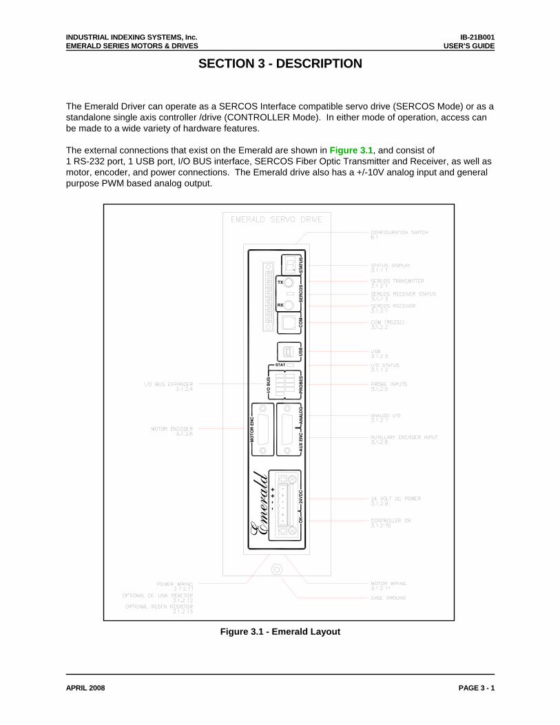
The Emerald Driver can operate as a SERCOS Interface compatible servo drive (SERCOS Mode) or as a standalone single axis controller /drive (CONTROLLER Mode). In either mode of operation, access can be made to a wide variety of hardware features. The external connections that exist on the Emerald are shown in Figure 3.1, and consist of 1 RS-232 port, 1 USB port, I/O BUS interface, SERCOS Fiber Optic Transmitter and Receiver, as well as motor, encoder, and power connections. The Emerald drive also has a +/-10V analog input and general purpose PWM based analog output.
Emerald
OK
24V
DC+
−+
−
US
BO
G
MO
TO
R E
NC
AU
X E
NC
LA
NA
PR
OB
ES
I/O B
US
STAT
SE
RC
OS
CO
MRX
ST
TX
AT
US
Figure 3.1 - Emerald Layout
INDUSTRIAL INDEXING SYSTEMS, Inc. IB-21B001 EMERALD SERIES MOTORS & DRIVES USER’S GUIDE
APRIL 2008 PAGE 3 - 2
3.1 COMPONENTS 3.1.1 STATUS INDICATORS
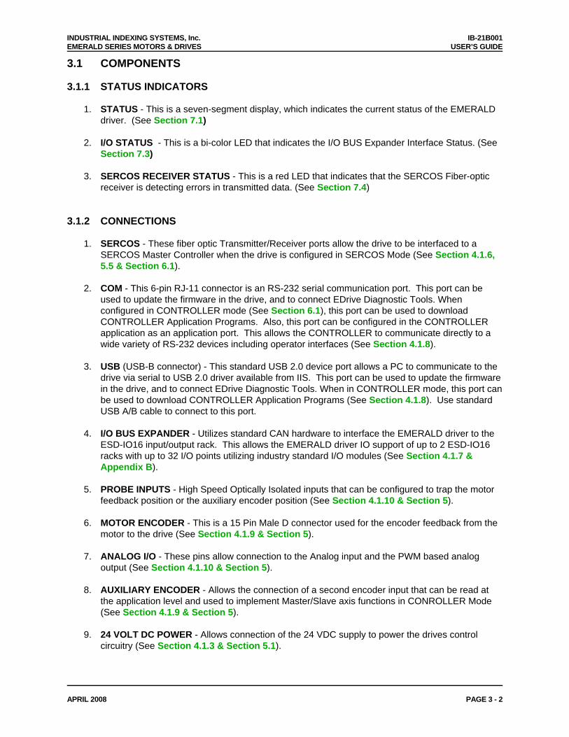
1. STATUS - This is a seven-segment display, which indicates the current status of the EMERALD driver. (See Section 7.1)
2. I/O STATUS - This is a bi-color LED that indicates the I/O BUS Expander Interface Status. (See
Section 7.3)
3. SERCOS RECEIVER STATUS - This is a red LED that indicates that the SERCOS Fiber-optic receiver is detecting errors in transmitted data. (See Section 7.4)
3.1.2 CONNECTIONS
1. SERCOS - These fiber optic Transmitter/Receiver ports allow the drive to be interfaced to a SERCOS Master Controller when the drive is configured in SERCOS Mode (See Section 4.1.6, 5.5 & Section 6.1).
2. COM - This 6-pin RJ-11 connector is an RS-232 serial communication port. This port can be
used to update the firmware in the drive, and to connect EDrive Diagnostic Tools. When configured in CONTROLLER mode (See Section 6.1), this port can be used to download CONTROLLER Application Programs. Also, this port can be configured in the CONTROLLER application as an application port. This allows the CONTROLLER to communicate directly to a wide variety of RS-232 devices including operator interfaces (See Section 4.1.8).
3. USB (USB-B connector) - This standard USB 2.0 device port allows a PC to communicate to the
drive via serial to USB 2.0 driver available from IIS. This port can be used to update the firmware in the drive, and to connect EDrive Diagnostic Tools. When in CONTROLLER mode, this port can be used to download CONTROLLER Application Programs (See Section 4.1.8). Use standard USB A/B cable to connect to this port.
4. I/O BUS EXPANDER - Utilizes standard CAN hardware to interface the EMERALD driver to the
ESD-IO16 input/output rack. This allows the EMERALD driver IO support of up to 2 ESD-IO16 racks with up to 32 I/O points utilizing industry standard I/O modules (See Section 4.1.7 & Appendix B).
5. PROBE INPUTS - High Speed Optically Isolated inputs that can be configured to trap the motor
feedback position or the auxiliary encoder position (See Section 4.1.10 & Section 5).
6. MOTOR ENCODER - This is a 15 Pin Male D connector used for the encoder feedback from the motor to the drive (See Section 4.1.9 & Section 5).
7. ANALOG I/O - These pins allow connection to the Analog input and the PWM based analog
output (See Section 4.1.10 & Section 5).
8. AUXILIARY ENCODER - Allows the connection of a second encoder input that can be read at the application level and used to implement Master/Slave axis functions in CONROLLER Mode (See Section 4.1.9 & Section 5).
9. 24 VOLT DC POWER - Allows connection of the 24 VDC supply to power the drives control
circuitry (See Section 4.1.3 & Section 5.1).
INDUSTRIAL INDEXING SYSTEMS, Inc. IB-21B001 EMERALD SERIES MOTORS & DRIVES USER’S GUIDE
APRIL 2008 PAGE 3 - 3
3.1.2 CONNECTIONS (cont’d) 10. CONTROLLER OK - A normally open dry contact that indicates the Drive is OK and ready to run
when the contact is closed (See Section 5).
11. MOTOR/POWER WIRING - These are terminal blocks used to wire the incoming AC line voltage as well as the motor power cable (See Section 5).
12. OPTIONAL DC LINK REACTOR - Many of the drivers support the addition of a DC Link reactor
to help with EMC noise suppression (See Section 5.4).
13. OPTIONAL REGEN RESISTOR - All of the drivers support the connection of external regeneration power resistors (See Section 5.3).
INDUSTRIAL INDEXING SYSTEMS, Inc. IB-21B001 EMERALD SERIES MOTORS & DRIVES USER’S GUIDE
SECTION 4 - SPECIFICATIONS
4.1 DRIVER SPECIFICATIONS
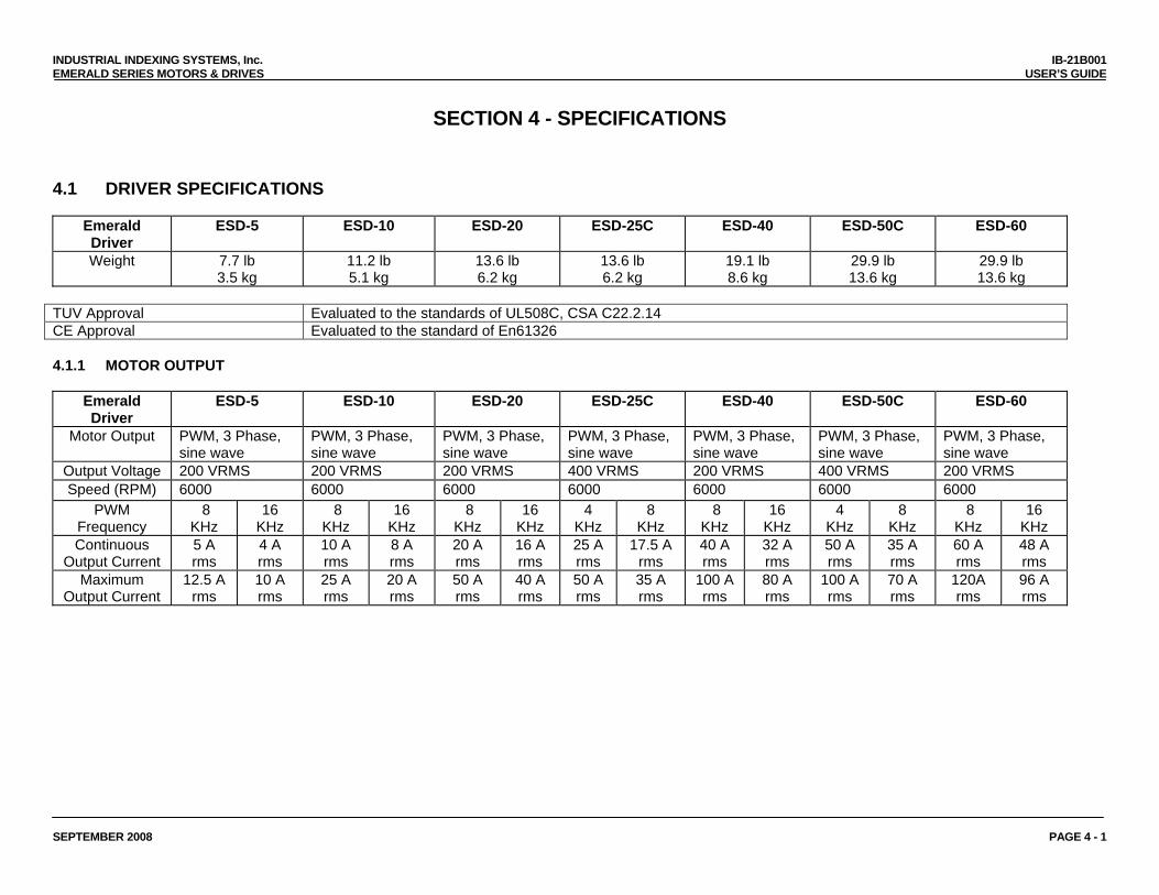
Emerald Driver
ESD-5 ESD-10 ESD-20 ESD-25C ESD-40 ESD-50C ESD-60
Weight 7.7 lb 3.5 kg
11.2 lb 5.1 kg
13.6 lb 6.2 kg
13.6 lb 6.2 kg
19.1 lb 8.6 kg
29.9 lb 13.6 kg
29.9 lb 13.6 kg
TUV Approval Evaluated to the standards of UL508C, CSA C22.2.14 CE Approval Evaluated to the standard of En61326 4.1.1 MOTOR OUTPUT
Emerald Driver
ESD-5 ESD-10 ESD-20 ESD-25C ESD-40 ESD-50C ESD-60
Motor Output PWM, 3 Phase, sine wave
PWM, 3 Phase, sine wave
PWM, 3 Phase, sine wave
PWM, 3 Phase, sine wave
PWM, 3 Phase, sine wave
PWM, 3 Phase, sine wave
PWM, 3 Phase, sine wave
Output Voltage 200 VRMS 200 VRMS 200 VRMS 400 VRMS 200 VRMS 400 VRMS 200 VRMS Speed (RPM) 6000 6000 6000 6000 6000 6000 6000
PWM Frequency
8 KHz
16 KHz
8 KHz
16 KHz
8 KHz
16 KHz
4 KHz
8 KHz
8 KHz
16 KHz
4 KHz
8 KHz
8 KHz
16 KHz
Continuous Output Current
5 A rms
4 A rms
10 A rms
8 A rms
20 A rms
16 A rms
25 A rms
17.5 A rms
40 A rms
32 A rms
50 A rms
35 A rms
60 A rms
48 A rms
Maximum Output Current
12.5 A rms
10 A rms
25 A rms
20 A rms
50 A rms
40 A rms
50 A rms
35 A rms
100 A rms
80 A rms
100 A rms
70 A rms
120A rms
96 A rms
SEPTEMBER 2008 PAGE 4 - 1
INDUSTRIAL INDEXING SYSTEMS, Inc. IB-21B001 EMERALD SERIES MOTORS & DRIVES USER’S GUIDE
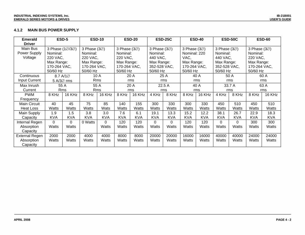
4.1.2 MAIN BUS POWER SUPPLY
Emerald Driver
ESD-5 ESD-10 ESD-20 ESD-25C ESD-40 ESD-50C ESD-60
Main Bus Power Supply
Voltage
3 Phase (1∅/3∅) Nominal: 220 VAC, Max Range: 170-264 VAC, 50/60 Hz
3 Phase (3∅) Nominal: 220 VAC, Max Range: 170-264 VAC, 50/60 Hz
3 Phase (3∅) Nominal: 220 VAC, Max Range: 170-264 VAC, 50/60 Hz
3 Phase (3∅) Nominal: 440 VAC, Max Range: 352-528 VAC, 50/60 Hz
3 Phase (3∅) Nominal: 220 VAC, Max Range: 170-264 VAC, 50/60 Hz
3 Phase (3∅) Nominal: 440 VAC, Max Range: 352-528 VAC, 50/60 Hz
3 Phase (3∅) Nominal: 220 VAC, Max Range: 170-264 VAC, 50/60 Hz
Continuous Input Current
8.7 A/1∅ 5 A/3∅ rms
10 A Rms
20 A rms
25 A rms
40 A rms
50 A rms
60 A rms
Max Inrush Current
55 A Rms
55 A Rms
20 A rms
22.5 A rms
40 A rms
33.7 A rms
63 A rms
PWM Frequency
8 KHz 16 KHz 8 KHz 16 KHz 8 KHz 16 KHz 4 KHz 8 KHz 8 KHz 16 KHz 4 KHz 8 KHz 8 KHz 16 KHz
Main Circuit Heat Loss
40 Watts
45 Watts
75 Watts
85 Wats
140 Watts
155 Watts
300 Watts
330 Watts
300 Watts
330 Watts
450 Watts
510 Watts
450 Watts
510 Watts
Main Supply Capacity
1.9 KVA
1.5 KVA
3.8 KVA
3.0 KVA
7.6 KVA
6.1 KVA
19.1 KVA
13.3 KVA
15.2 KVA
12.2 KVA
38.1 KVA
26.7 KVA
22.9 KVA
18.3 KVA
Internal Regen Absorption Capacity
0 Watts
0 Watts
0 Watts 0 Watts
120 Watts
120 Watts
0 Watts
0 Watts
120 Watts
120 Watts
0 Watts
0 Watts
300 Watts
300 Watts
External Regen Absorption Capacity
2000 Watts
2000 Watts
4000 Watts
4000 Watts
8000 Watts
8000 Watts
20000 Watts
20000 Watts
16000 Watts
16000 Watts
40000 Watts
40000 Watts
24000 Watts
24000 Watts
APRIL 2008 PAGE 4 - 2
INDUSTRIAL INDEXING SYSTEMS, Inc. IB-21B001 EMERALD SERIES MOTORS & DRIVES USER’S GUIDE
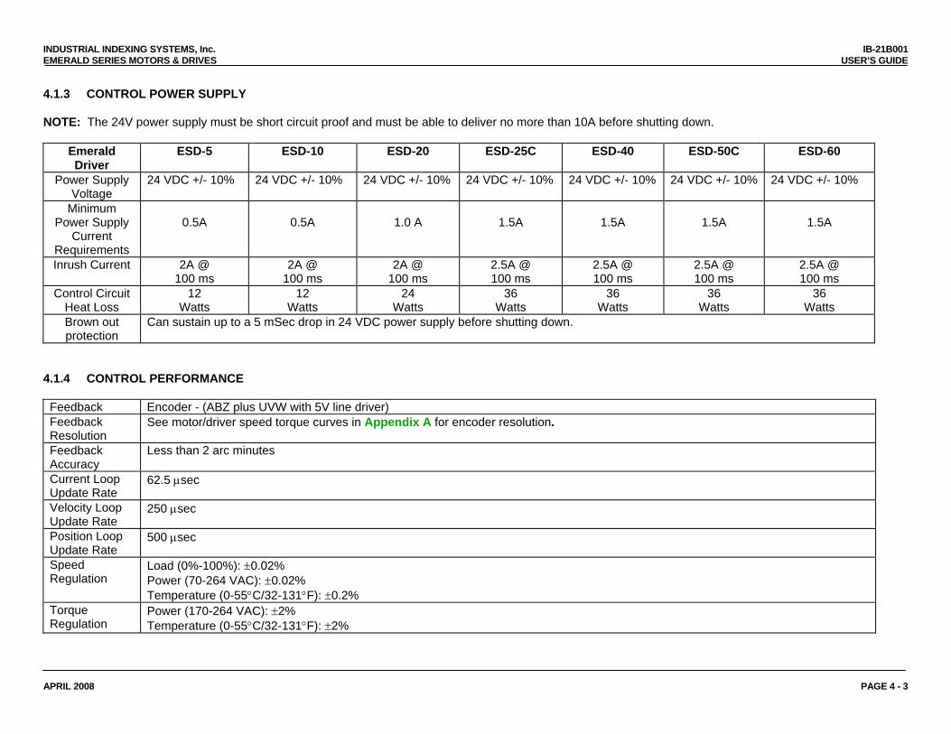
4.1.3 CONTROL POWER SUPPLY NOTE: The 24V power supply must be short circuit proof and must be able to deliver no more than 10A before shutting down.
Emerald Driver
ESD-5 ESD-10 ESD-20 ESD-25C ESD-40 ESD-50C ESD-60
Power Supply Voltage
24 VDC +/- 10% 24 VDC +/- 10% 24 VDC +/- 10% 24 VDC +/- 10% 24 VDC +/- 10% 24 VDC +/- 10% 24 VDC +/- 10%
Minimum Power Supply
Current Requirements
0.5A
0.5A
1.0 A
1.5A
1.5A
1.5A
1.5A
Inrush Current 2A @ 100 ms
2A @ 100 ms
2A @ 100 ms
2.5A @ 100 ms
2.5A @ 100 ms
2.5A @ 100 ms
2.5A @ 100 ms
Control Circuit Heat Loss
12 Watts
12 Watts
24 Watts
36 Watts
36 Watts
36 Watts
36 Watts
Brown out protection
Can sustain up to a 5 mSec drop in 24 VDC power supply before shutting down.
4.1.4 CONTROL PERFORMANCE Feedback Encoder - (ABZ plus UVW with 5V line driver) Feedback Resolution
See motor/driver speed torque curves in Appendix A for encoder resolution.
Feedback Accuracy
Less than 2 arc minutes
Current Loop Update Rate
62.5 μsec
Velocity Loop Update Rate
250 μsec
Position Loop Update Rate
500 μsec
Speed Regulation
Load (0%-100%): ±0.02% Power (70-264 VAC): ±0.02% Temperature (0-55°C/32-131°F): ±0.2%
Torque Regulation
Power (170-264 VAC): ±2% Temperature (0-55°C/32-131°F): ±2%
APRIL 2008 PAGE 4 - 3
INDUSTRIAL INDEXING SYSTEMS, Inc. IB-21B001 EMERALD SERIES MOTORS & DRIVES USER’S GUIDE
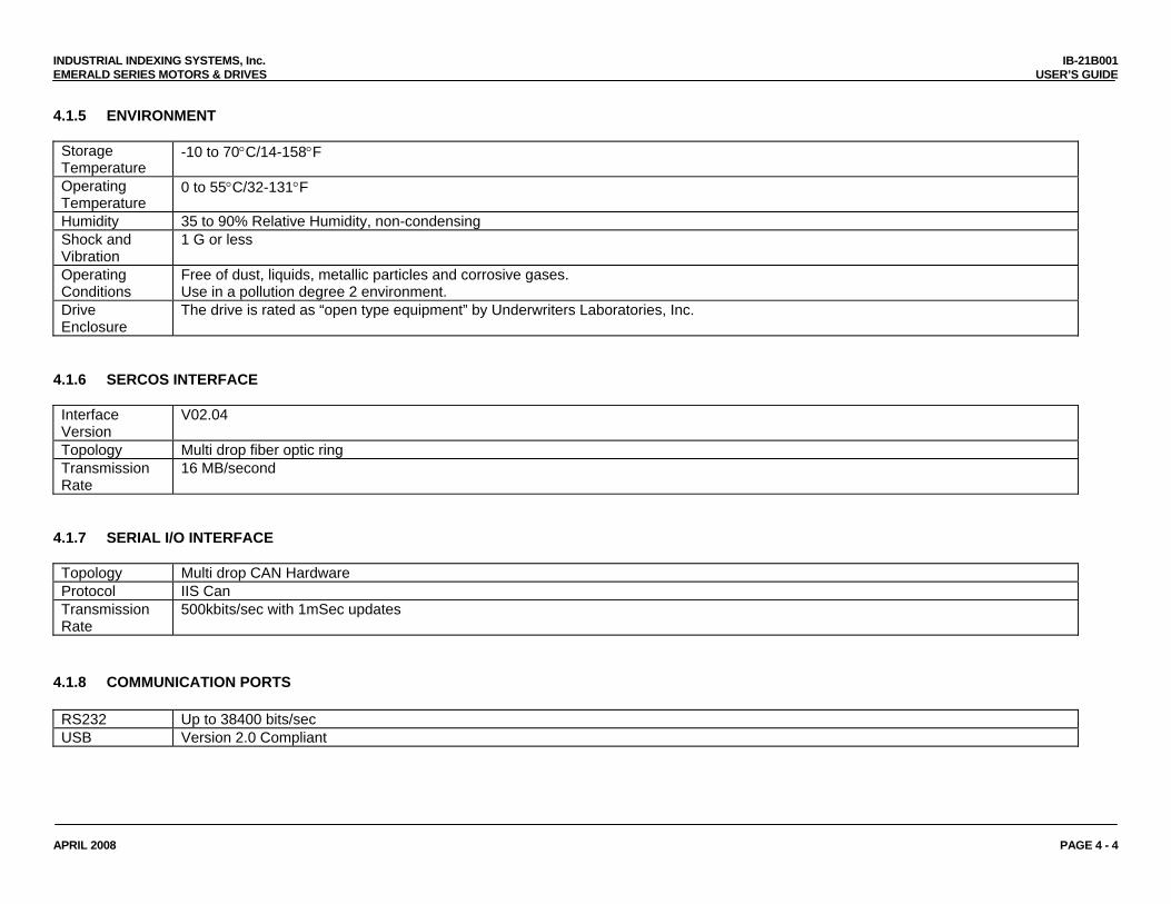
4.1.5 ENVIRONMENT Storage Temperature
-10 to 70°C/14-158°F
Operating Temperature
0 to 55°C/32-131°F
Humidity 35 to 90% Relative Humidity, non-condensing Shock and Vibration
1 G or less
Operating Conditions
Free of dust, liquids, metallic particles and corrosive gases. Use in a pollution degree 2 environment.
Drive Enclosure
The drive is rated as “open type equipment” by Underwriters Laboratories, Inc.
4.1.6 SERCOS INTERFACE Interface Version
V02.04
Topology Multi drop fiber optic ring Transmission Rate
16 MB/second
4.1.7 SERIAL I/O INTERFACE Topology Multi drop CAN Hardware Protocol IIS Can Transmission Rate
500kbits/sec with 1mSec updates
4.1.8 COMMUNICATION PORTS RS232 Up to 38400 bits/sec USB Version 2.0 Compliant
APRIL 2008 PAGE 4 - 4
INDUSTRIAL INDEXING SYSTEMS, Inc. IB-21B001 EMERALD SERIES MOTORS & DRIVES USER’S GUIDE
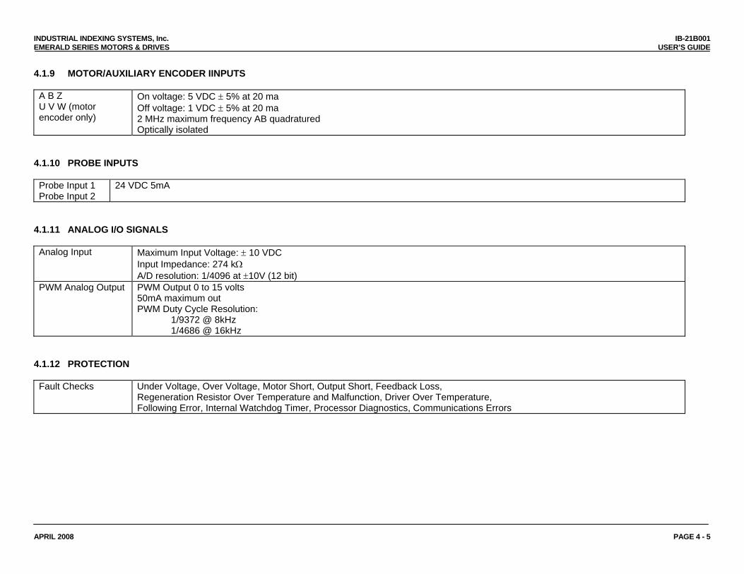
4.1.9 MOTOR/AUXILIARY ENCODER IINPUTS A B Z U V W (motor encoder only)
On voltage: 5 VDC ± 5% at 20 ma Off voltage: 1 VDC ± 5% at 20 ma 2 MHz maximum frequency AB quadratured Optically isolated
4.1.10 PROBE INPUTS Probe Input 1 Probe Input 2
24 VDC 5mA
4.1.11 ANALOG I/O SIGNALS Analog Input Maximum Input Voltage: ± 10 VDC
Input Impedance: 274 kΩ A/D resolution: 1/4096 at ±10V (12 bit)
PWM Analog Output PWM Output 0 to 15 volts 50mA maximum out PWM Duty Cycle Resolution:
1/9372 @ 8kHz 1/4686 @ 16kHz
4.1.12 PROTECTION Fault Checks Under Voltage, Over Voltage, Motor Short, Output Short, Feedback Loss,
Regeneration Resistor Over Temperature and Malfunction, Driver Over Temperature, Following Error, Internal Watchdog Timer, Processor Diagnostics, Communications Errors
APRIL 2008 PAGE 4 - 5
INDUSTRIAL INDEXING SYSTEMS, Inc. IB-21B001 EMERALD SERIES MOTORS & DRIVES USER’S GUIDE
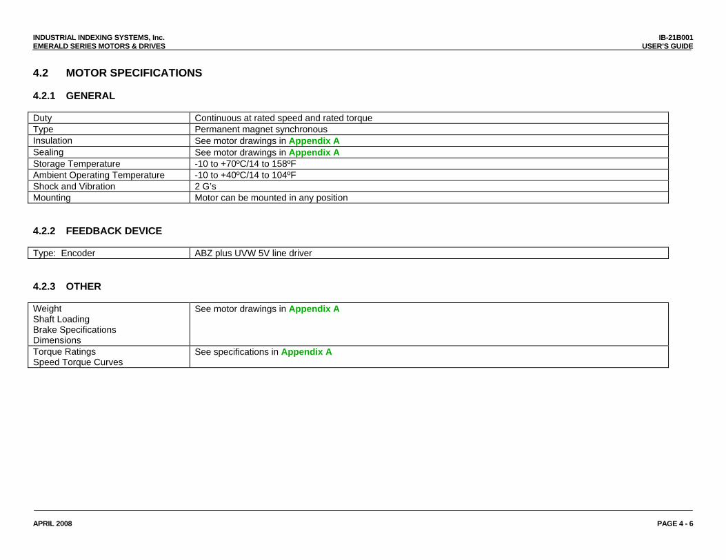
4.2 MOTOR SPECIFICATIONS 4.2.1 GENERAL Duty Continuous at rated speed and rated torque Type Permanent magnet synchronous Insulation See motor drawings in Appendix A Sealing See motor drawings in Appendix A Storage Temperature -10 to +70ºC/14 to 158ºF Ambient Operating Temperature -10 to +40ºC/14 to 104ºF Shock and Vibration 2 G’s Mounting Motor can be mounted in any position 4.2.2 FEEDBACK DEVICE Type: Encoder ABZ plus UVW 5V line driver 4.2.3 OTHER Weight Shaft Loading Brake Specifications Dimensions
See motor drawings in Appendix A
Torque Ratings Speed Torque Curves
See specifications in Appendix A
APRIL 2008 PAGE 4 - 6
INDUSTRIAL INDEXING SYSTEMS, Inc. IB-21B001 EMERALD SERIES MOTORS & DRIVES USER’S GUIDE
APRIL 2009 PAGE 5 - 1
SECTION 5 - CONNECTIONS/WIRING
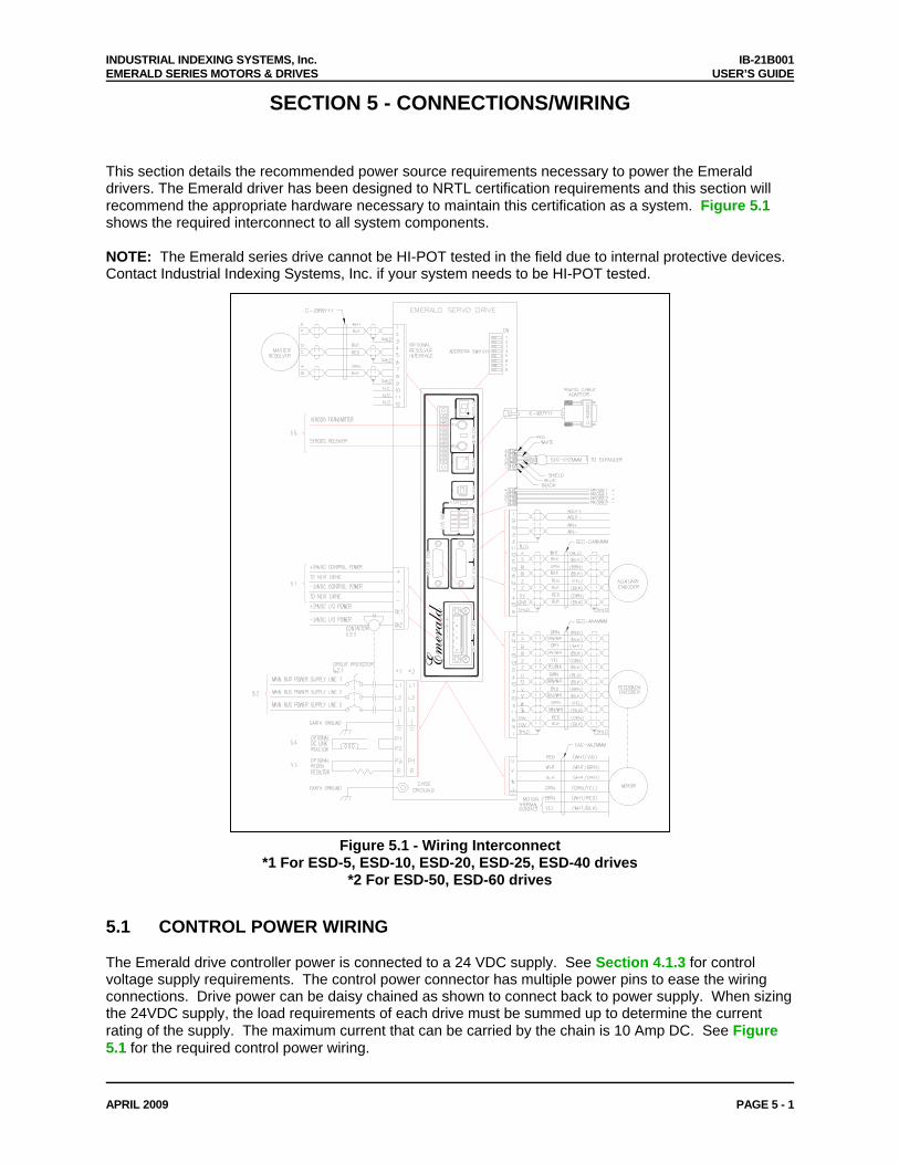
This section details the recommended power source requirements necessary to power the Emerald drivers. The Emerald driver has been designed to NRTL certification requirements and this section will recommend the appropriate hardware necessary to maintain this certification as a system. Figure 5.1 shows the required interconnect to all system components. NOTE: The Emerald series drive cannot be HI-POT tested in the field due to internal protective devices. Contact Industrial Indexing Systems, Inc. if your system needs to be HI-POT tested.
Emerald
Figure 5.1 - Wiring Interconnect *1 For ESD-5, ESD-10, ESD-20, ESD-25, ESD-40 drives
*2 For ESD-50, ESD-60 drives
5.1 CONTROL POWER WIRING The Emerald drive controller power is connected to a 24 VDC supply. See Section 4.1.3 for control voltage supply requirements. The control power connector has multiple power pins to ease the wiring connections. Drive power can be daisy chained as shown to connect back to power supply. When sizing the 24VDC supply, the load requirements of each drive must be summed up to determine the current rating of the supply. The maximum current that can be carried by the chain is 10 Amp DC. See Figure 5.1 for the required control power wiring.
INDUSTRIAL INDEXING SYSTEMS, Inc. IB-21B001 EMERALD SERIES MOTORS & DRIVES USER’S GUIDE
APRIL 2008 PAGE 5 - 2
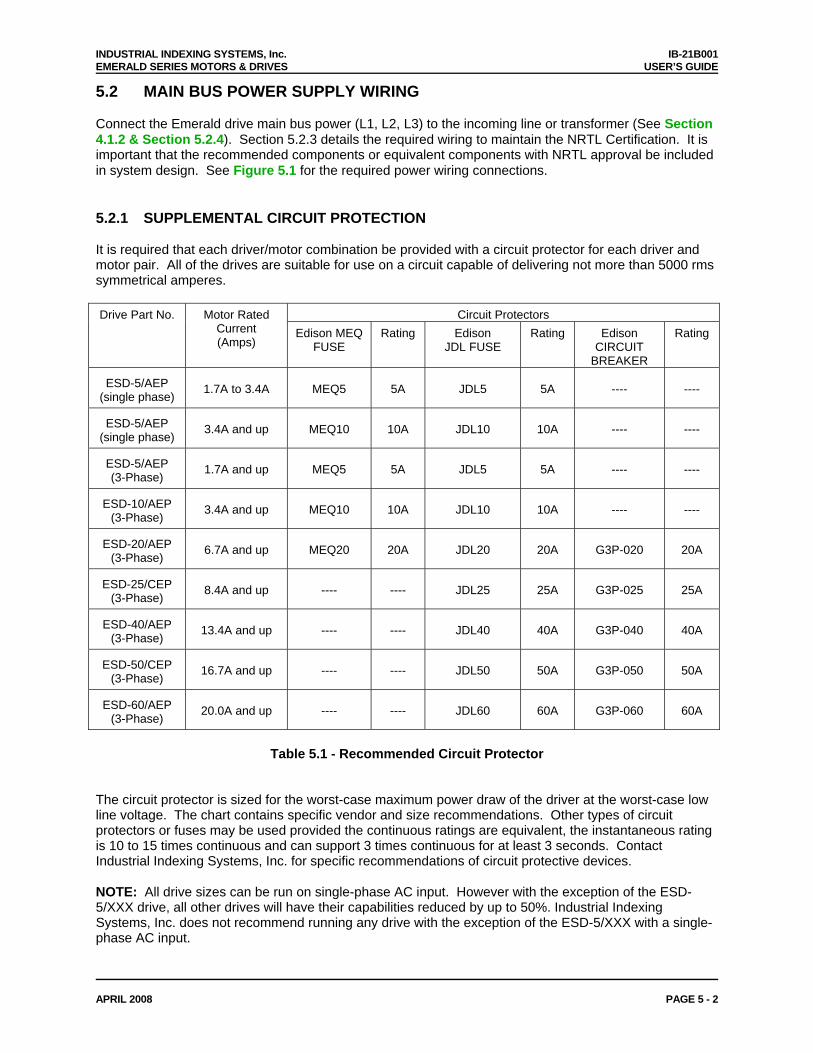
5.2 MAIN BUS POWER SUPPLY WIRING Connect the Emerald drive main bus power (L1, L2, L3) to the incoming line or transformer (See Section 4.1.2 & Section 5.2.4). Section 5.2.3 details the required wiring to maintain the NRTL Certification. It is important that the recommended components or equivalent components with NRTL approval be included in system design. See Figure 5.1 for the required power wiring connections. 5.2.1 SUPPLEMENTAL CIRCUIT PROTECTION It is required that each driver/motor combination be provided with a circuit protector for each driver and motor pair. All of the drives are suitable for use on a circuit capable of delivering not more than 5000 rms symmetrical amperes.
Circuit Protectors Drive Part No. Motor Rated Current (Amps)
Edison MEQ FUSE
Rating Edison JDL FUSE
Rating Edison CIRCUIT
BREAKER
Rating
ESD-5/AEP (single phase)
1.7A to 3.4A
MEQ5
5A
JDL5
5A
----
----
ESD-5/AEP (single phase)
3.4A and up
MEQ10
10A
JDL10
10A
----
----
ESD-5/AEP (3-Phase)
1.7A and up
MEQ5
5A
JDL5
5A
----
----
ESD-10/AEP (3-Phase)
3.4A and up
MEQ10
10A
JDL10
10A
----
----
ESD-20/AEP (3-Phase)
6.7A and up
MEQ20
20A
JDL20
20A
G3P-020
20A
ESD-25/CEP (3-Phase)
8.4A and up
----
----
JDL25
25A
G3P-025
25A
ESD-40/AEP (3-Phase)
13.4A and up
----
----
JDL40
40A
G3P-040
40A
ESD-50/CEP (3-Phase)
16.7A and up
----
----
JDL50
50A
G3P-050
50A
ESD-60/AEP (3-Phase)
20.0A and up
----
----
JDL60
60A
G3P-060
60A
Table 5.1 - Recommended Circuit Protector
The circuit protector is sized for the worst-case maximum power draw of the driver at the worst-case low line voltage. The chart contains specific vendor and size recommendations. Other types of circuit protectors or fuses may be used provided the continuous ratings are equivalent, the instantaneous rating is 10 to 15 times continuous and can support 3 times continuous for at least 3 seconds. Contact Industrial Indexing Systems, Inc. for specific recommendations of circuit protective devices. NOTE: All drive sizes can be run on single-phase AC input. However with the exception of the ESD-5/XXX drive, all other drives will have their capabilities reduced by up to 50%. Industrial Indexing Systems, Inc. does not recommend running any drive with the exception of the ESD-5/XXX with a single-phase AC input.
INDUSTRIAL INDEXING SYSTEMS, Inc. IB-21B001 EMERALD SERIES MOTORS & DRIVES USER’S GUIDE
APRIL 2008 PAGE 5 - 3
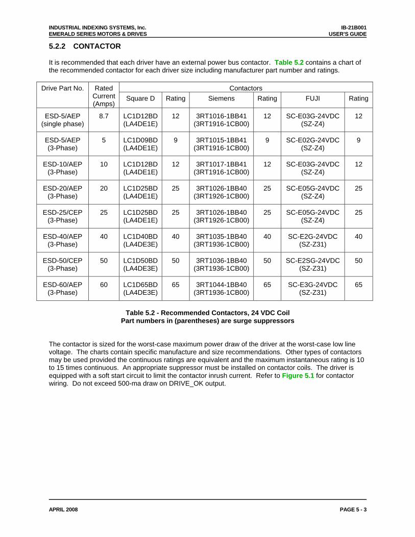
5.2.2 CONTACTOR It is recommended that each driver have an external power bus contactor. Table 5.2 contains a chart of the recommended contactor for each driver size including manufacturer part number and ratings.
Contactors Drive Part No. Rated Current (Amps)
Square D Rating Siemens Rating FUJI Rating
ESD-5/AEP (single phase)
8.7 LC1D12BD (LA4DE1E)
12 3RT1016-1BB41 (3RT1916-1CB00)
12 SC-E03G-24VDC (SZ-Z4)
12
ESD-5/AEP (3-Phase)
5 LC1D09BD (LA4DE1E)
9 3RT1015-1BB41 (3RT1916-1CB00)
9 SC-E02G-24VDC (SZ-Z4)
9
ESD-10/AEP (3-Phase)
10
LC1D12BD (LA4DE1E)
12 3RT1017-1BB41 (3RT1916-1CB00)
12 SC-E03G-24VDC (SZ-Z4)
12
ESD-20/AEP (3-Phase)
20 LC1D25BD (LA4DE1E)
25 3RT1026-1BB40 (3RT1926-1CB00)
25 SC-E05G-24VDC (SZ-Z4)
25
ESD-25/CEP (3-Phase)
25 LC1D25BD (LA4DE1E)
25 3RT1026-1BB40 (3RT1926-1CB00)
25 SC-E05G-24VDC (SZ-Z4)
25
ESD-40/AEP (3-Phase)
40 LC1D40BD (LA4DE3E)
40 3RT1035-1BB40 (3RT1936-1CB00)
40 SC-E2G-24VDC (SZ-Z31)
40
ESD-50/CEP (3-Phase)
50 LC1D50BD (LA4DE3E)
50 3RT1036-1BB40 (3RT1936-1CB00)
50 SC-E2SG-24VDC (SZ-Z31)
50
ESD-60/AEP (3-Phase)
60 LC1D65BD (LA4DE3E)
65 3RT1044-1BB40 (3RT1936-1CB00)
65 SC-E3G-24VDC (SZ-Z31)
65
Table 5.2 - Recommended Contactors, 24 VDC Coil
Part numbers in (parentheses) are surge suppressors The contactor is sized for the worst-case maximum power draw of the driver at the worst-case low line voltage. The charts contain specific manufacture and size recommendations. Other types of contactors may be used provided the continuous ratings are equivalent and the maximum instantaneous rating is 10 to 15 times continuous. An appropriate suppressor must be installed on contactor coils. The driver is equipped with a soft start circuit to limit the contactor inrush current. Refer to Figure 5.1 for contactor wiring. Do not exceed 500-ma draw on DRIVE_OK output.
INDUSTRIAL INDEXING SYSTEMS, Inc. IB-21B001 EMERALD SERIES MOTORS & DRIVES USER’S GUIDE
APRIL 2008 PAGE 5 - 4
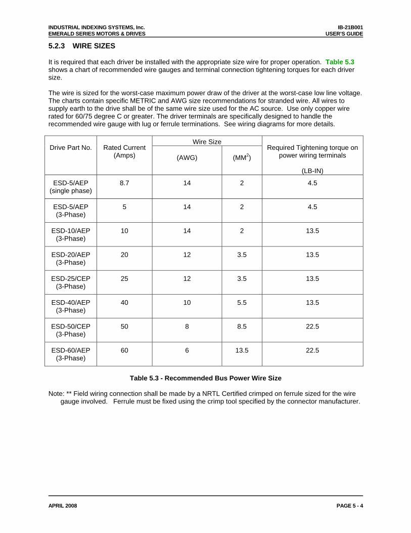
5.2.3 WIRE SIZES It is required that each driver be installed with the appropriate size wire for proper operation. Table 5.3 shows a chart of recommended wire gauges and terminal connection tightening torques for each driver size. The wire is sized for the worst-case maximum power draw of the driver at the worst-case low line voltage. The charts contain specific METRIC and AWG size recommendations for stranded wire. All wires to supply earth to the drive shall be of the same wire size used for the AC source. Use only copper wire rated for 60/75 degree C or greater. The driver terminals are specifically designed to handle the recommended wire gauge with lug or ferrule terminations. See wiring diagrams for more details.
Wire Size Drive Part No.
Rated Current
(Amps)
(AWG)
(MM2)
Required Tightening torque on
power wiring terminals
(LB-IN)
ESD-5/AEP (single phase)
8.7 14 2 4.5
ESD-5/AEP (3-Phase)
5 14 2 4.5
ESD-10/AEP (3-Phase)
10 14 2 13.5
ESD-20/AEP (3-Phase)
20 12 3.5 13.5
ESD-25/CEP (3-Phase)
25 12 3.5 13.5
ESD-40/AEP (3-Phase)
40 10 5.5 13.5
ESD-50/CEP (3-Phase)
50 8 8.5 22.5
ESD-60/AEP (3-Phase)
60 6 13.5 22.5
Table 5.3 - Recommended Bus Power Wire Size
Note: ** Field wiring connection shall be made by a NRTL Certified crimped on ferrule sized for the wire
gauge involved. Ferrule must be fixed using the crimp tool specified by the connector manufacturer.
INDUSTRIAL INDEXING SYSTEMS, Inc. IB-21B001 EMERALD SERIES MOTORS & DRIVES USER’S GUIDE
APRIL 2008 PAGE 5 - 5
5.2.4 TRANSFORMERS
0.85
Isolating the driver from the facility power line with a transformer is recommended but not required. A transformer may be required to step down or step up the facility power line to meet the driver voltage specifications in Section 4. If a transformer is used, select a transformer with the following characteristics: • Isolation type. • Load regulation less than 10%. • Ability to provide 3 times rated current for 3 to 5 seconds without saturation. • Ability to drive load with a power factor of 0.85. • Primary or secondary taps to provide -10%; nominal; +10%; supply voltage. To achieve maximum performance from the driver, the power input to the driver should be as close to nominal driver input voltage rating as possible. The facility line voltage varies through wide ranges in many parts of the world and it is recommended to match the nominal facility voltage to the nominal input voltage rating of the driver with a transformer. This gives the system the maximum operating range with facility line voltage fluctuations. If the line voltage is too low, intermittent under voltage alarms may occur. A high line voltage will result in excessive regeneration dumping or intermittent over voltage alarms. Buck boost transformers may be used to optimally match the facility line voltage to the driver line voltage rating. Buck boost transformers can be used with or without an isolation transformer. If buck boost transformers are used in conjunction with an isolation transformer, it is best to put the buck boost transformers on the primary side of the isolation transformer. As a general rule the transformer rating can be calculated using the following formulas: For single phase transformer: Rated Mechanical Output (Watts) Transformer Capacity (VA) = ---------------------------------------------------- 0.7 Where: Rated Mechanical Output is from Emerald Motor and Drive Package rating. 0.7 = motor/drive efficiency and single phase full wave rectifier factor Example: Select transformer for a Delta S-200HRA motor/drive package 200 Transformer Capacity (VA) = ------------ = 285 VA 0.7 For three phase transformer: Rated Mechanical Output (Watts) Transformer Capacity (Watts) = --------------------------------------------------- 0.85 Where: Rated Mechanical Output is from Emerald Motor and Drive Package rating. 0.85 is motor/drive efficiency and three phase rectifier factor Example: Select transformer for a Delta S-6500HRA motor/drive package 6500 Transformer Capacity (VA) = ---------------- = 7647 VA
INDUSTRIAL INDEXING SYSTEMS, Inc. IB-21B001 EMERALD SERIES MOTORS & DRIVES USER’S GUIDE
APRIL 2008 PAGE 5 - 6
5.2.4 TRANSFORMERS (cont’d) One transformer can supply multiple motor/driver packages. Simply add the rated mechanical output of the motor/driver packages together and use the above formulas. If one transformer is used to supply multiple drivers, be sure to protect each driver with the appropriate circuit breaker or fuse. IIS offers a full line of transformers for various line voltage and frequencies, enclosed and open frame types. Contact IIS Application Engineering Department for full details. 5.2.5 WIRING PRACTICES AND GROUNDING All wiring must conform to accept standards such as NEMA and NEC codes. Signal and low voltage I/O wires must be physically separated from high voltage wires by at least 12 inches or separated by a suitable barrier such as steel conduit or wiring trough separator. The driver must be adequately grounded for proper operation and to provide personnel safety. The proper grounding technique is shown in Figure 5.1. 5.3 DRIVER REGENERATION CAPACITIES The Emerald motor and driver have the ability to act as a brake for a rotating load. This condition typically occurs during the deceleration of the load or when the system is stopping a vertical load such as an elevator or lift. In both cases, the driver may have to absorb the mechanical and potential energy in the system. The driver must absorb the energy if the energy in the load exceeds to mechanical losses in the system. The driver has 2 ways to absorb the energy from the load.
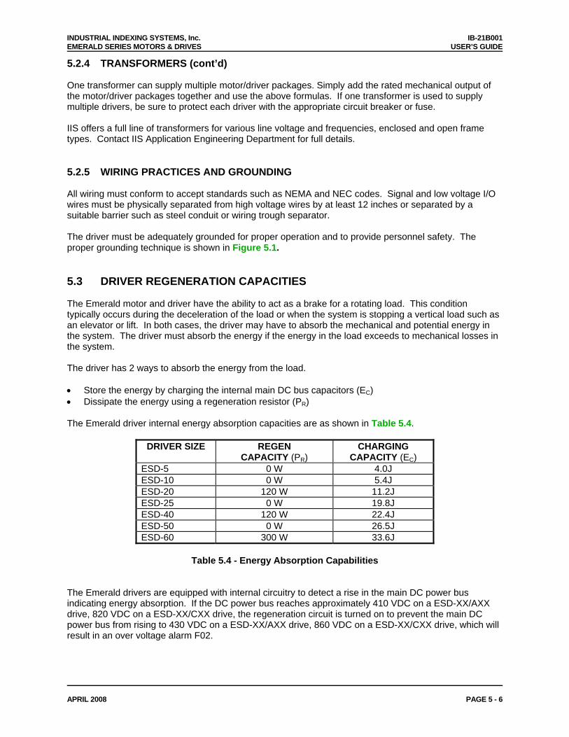
• Store the energy by charging the internal main DC bus capacitors (EC) • Dissipate the energy using a regeneration resistor (PR) The Emerald driver internal energy absorption capacities are as shown in Table 5.4.
DRIVER SIZE REGEN CAPACITY (PR)
CHARGING CAPACITY (EC)
ESD-5 0 W 4.0J ESD-10 0 W 5.4J ESD-20 120 W 11.2J ESD-25 0 W 19.8J ESD-40 120 W 22.4J ESD-50 0 W 26.5J ESD-60 300 W 33.6J
Table 5.4 - Energy Absorption Capabilities
The Emerald drivers are equipped with internal circuitry to detect a rise in the main DC power bus indicating energy absorption. If the DC power bus reaches approximately 410 VDC on a ESD-XX/AXX drive, 820 VDC on a ESD-XX/CXX drive, the regeneration circuit is turned on to prevent the main DC power bus from rising to 430 VDC on a ESD-XX/AXX drive, 860 VDC on a ESD-XX/CXX drive, which will result in an over voltage alarm F02.
INDUSTRIAL INDEXING SYSTEMS, Inc. IB-21B001 EMERALD SERIES MOTORS & DRIVES USER’S GUIDE
APRIL 2008 PAGE 5 - 7
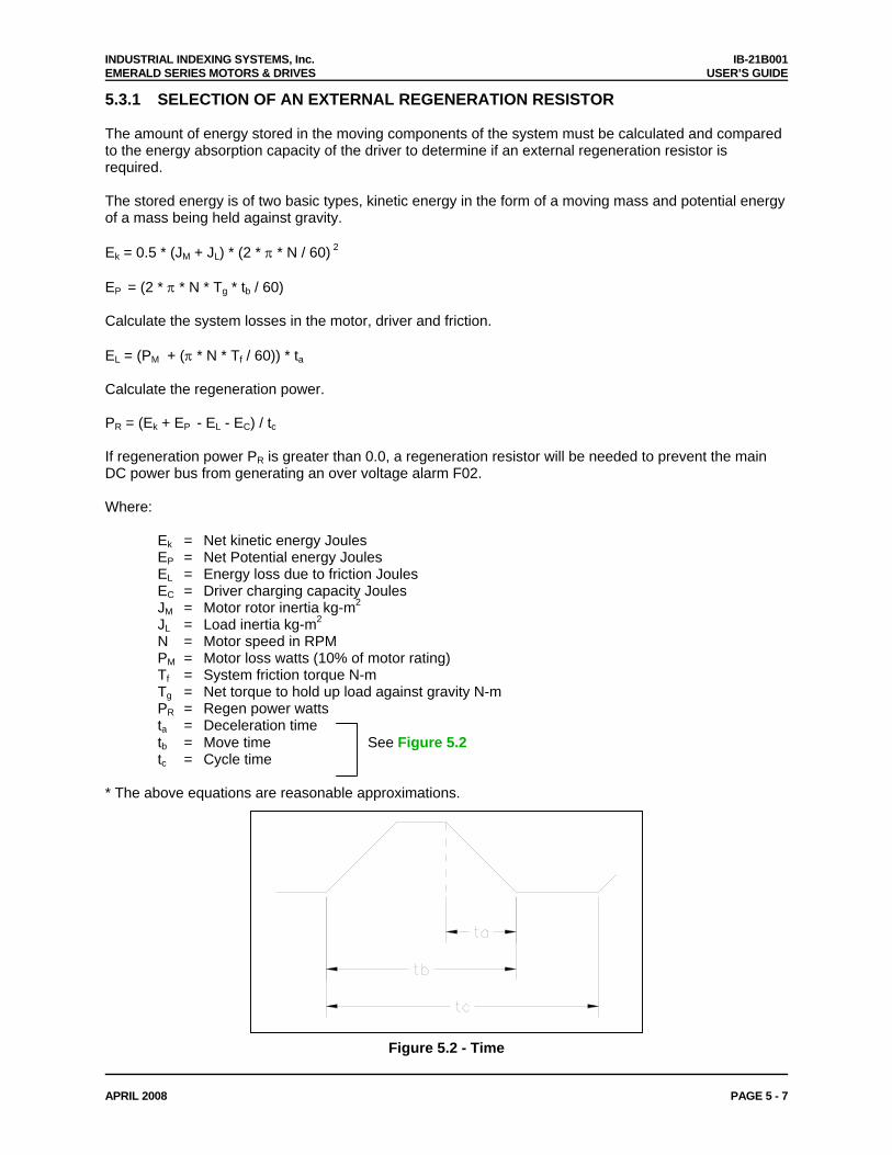
5.3.1 SELECTION OF AN EXTERNAL REGENERATION RESISTOR The amount of energy stored in the moving components of the system must be calculated and compared to the energy absorption capacity of the driver to determine if an external regeneration resistor is required. The stored energy is of two basic types, kinetic energy in the form of a moving mass and potential energy of a mass being held against gravity. Ek = 0.5 * (JM + JL) * (2 * π * N / 60) 2
EP = (2 * π * N * Tg * tb / 60) Calculate the system losses in the motor, driver and friction. EL = (PM + (π * N * Tf / 60)) * ta Calculate the regeneration power. PR = (Ek + EP - EL - EC) / tc If regeneration power PR is greater than 0.0, a regeneration resistor will be needed to prevent the main DC power bus from generating an over voltage alarm F02. Where: Ek = Net kinetic energy Joules EP = Net Potential energy Joules EL = Energy loss due to friction Joules EC = Driver charging capacity Joules JM = Motor rotor inertia kg-m2
JL = Load inertia kg-m2
N = Motor speed in RPM PM = Motor loss watts (10% of motor rating) Tf = System friction torque N-m Tg = Net torque to hold up load against gravity N-m PR = Regen power watts ta = Deceleration time tb = Move time See Figure 5.2 tc = Cycle time * The above equations are reasonable approximations.
Figure 5.2 - Time
INDUSTRIAL INDEXING SYSTEMS, Inc. IB-21B001 EMERALD SERIES MOTORS & DRIVES USER’S GUIDE
APRIL 2008 PAGE 5 - 8
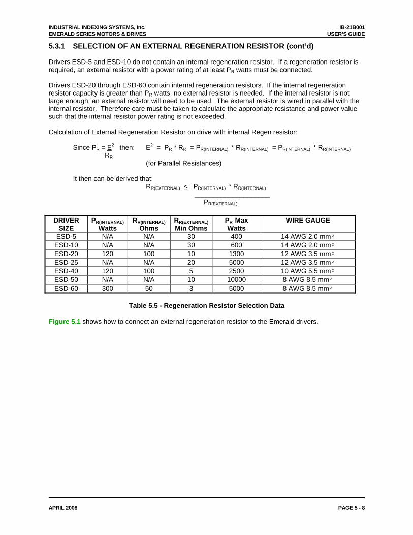
5.3.1 SELECTION OF AN EXTERNAL REGENERATION RESISTOR (cont’d) Drivers ESD-5 and ESD-10 do not contain an internal regeneration resistor. If a regeneration resistor is required, an external resistor with a power rating of at least PR watts must be connected. Drivers ESD-20 through ESD-60 contain internal regeneration resistors. If the internal regeneration resistor capacity is greater than PR watts, no external resistor is needed. If the internal resistor is not large enough, an external resistor will need to be used. The external resistor is wired in parallel with the internal resistor. Therefore care must be taken to calculate the appropriate resistance and power value such that the internal resistor power rating is not exceeded. Calculation of External Regeneration Resistor on drive with internal Regen resistor: Since PR = E2 then: E2 = PR * RR = PR(INTERNAL) * RR(INTERNAL) = PR(INTERNAL) * RR(INTERNAL) RR
(for Parallel Resistances) It then can be derived that:
RR(EXTERNAL) < PR(INTERNAL) * RR(INTERNAL) ____________________ PR(EXTERNAL)
DRIVER SIZE
PR(INTERNAL) Watts
RR(INTERNAL)Ohms
RR(EXTERNAL)Min Ohms
PR Max Watts
WIRE GAUGE
ESD-5 N/A N/A 30 400 14 AWG 2.0 mm² ESD-10 N/A N/A 30 600 14 AWG 2.0 mm² ESD-20 120 100 10 1300 12 AWG 3.5 mm² ESD-25 N/A N/A 20 5000 12 AWG 3.5 mm² ESD-40 120 100 5 2500 10 AWG 5.5 mm² ESD-50 N/A N/A 10 10000 8 AWG 8.5 mm² ESD-60 300 50 3 5000 8 AWG 8.5 mm²
Table 5.5 - Regeneration Resistor Selection Data Figure 5.1 shows how to connect an external regeneration resistor to the Emerald drivers.
INDUSTRIAL INDEXING SYSTEMS, Inc. IB-21B001 EMERALD SERIES MOTORS & DRIVES USER’S GUIDE
APRIL 2008 PAGE 5 - 9
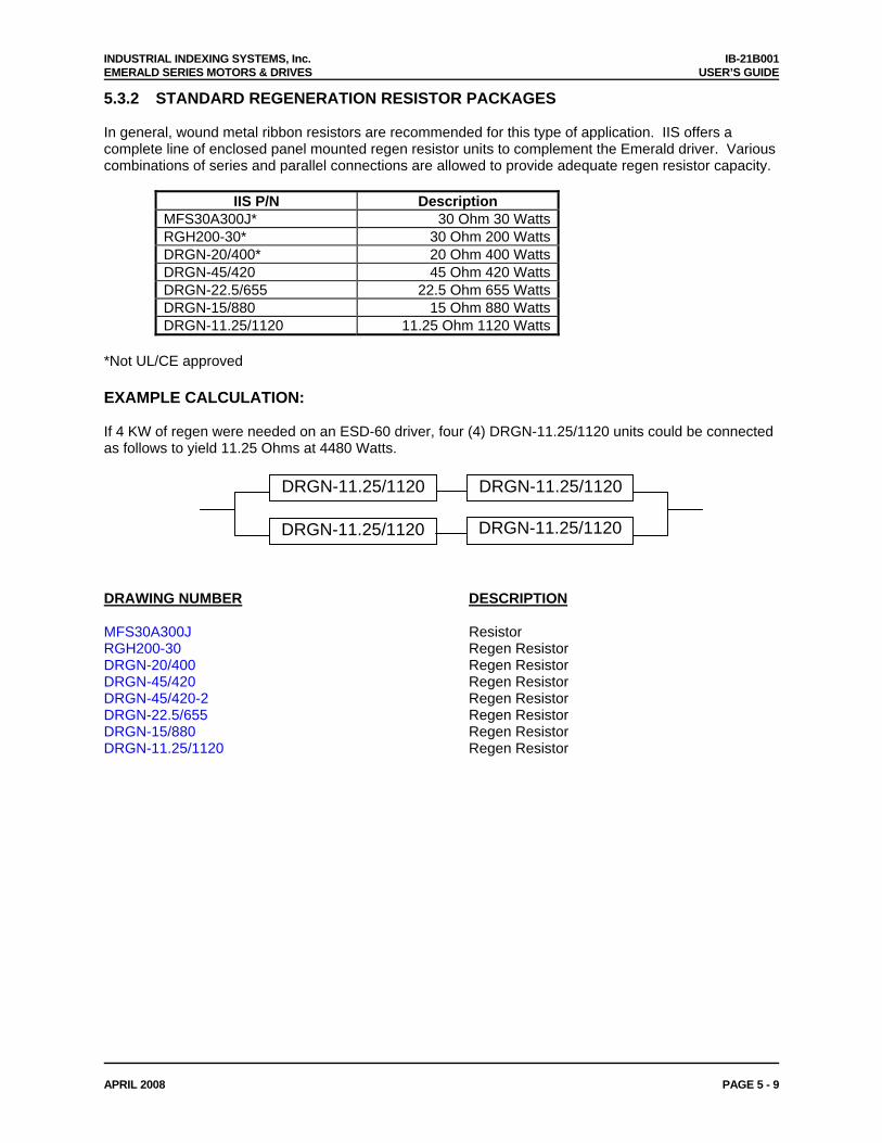
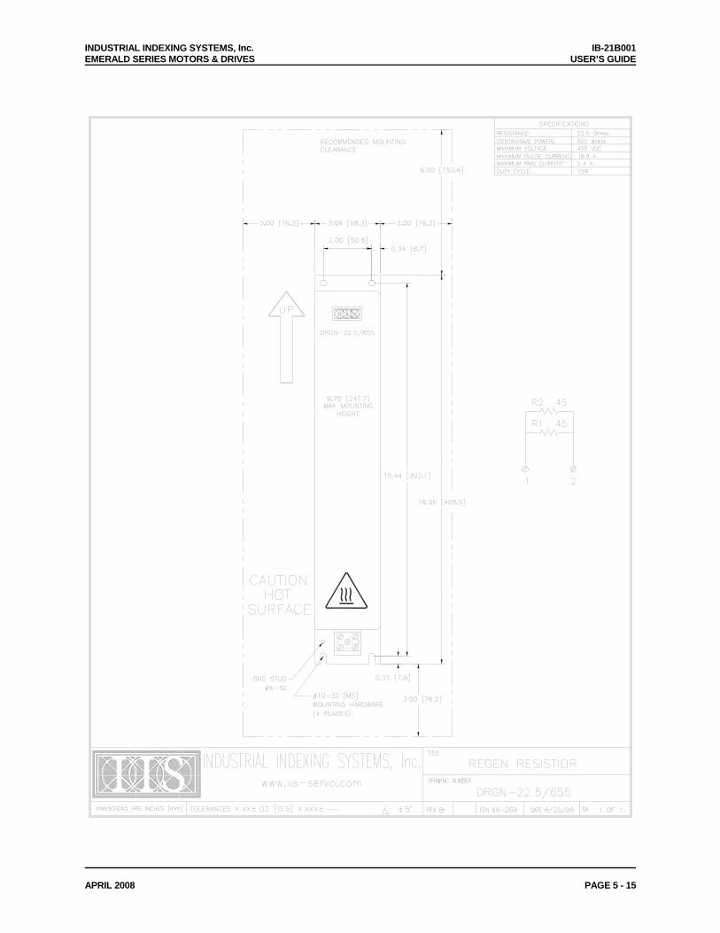
5.3.2 STANDARD REGENERATION RESISTOR PACKAGES In general, wound metal ribbon resistors are recommended for this type of application. IIS offers a complete line of enclosed panel mounted regen resistor units to complement the Emerald driver. Various combinations of series and parallel connections are allowed to provide adequate regen resistor capacity.
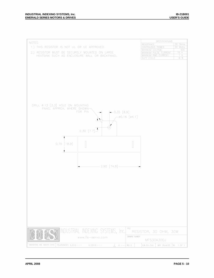
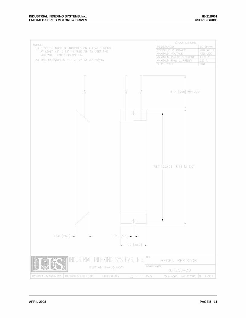
IIS P/N Description MFS30A300J* 30 Ohm 30 WattsRGH200-30* 30 Ohm 200 WattsDRGN-20/400* 20 Ohm 400 WattsDRGN-45/420 45 Ohm 420 WattsDRGN-22.5/655 22.5 Ohm 655 WattsDRGN-15/880 15 Ohm 880 WattsDRGN-11.25/1120 11.25 Ohm 1120 Watts
*Not UL/CE approved EXAMPLE CALCULATION: If 4 KW of regen were needed on an ESD-60 driver, four (4) DRGN-11.25/1120 units could be connected as follows to yield 11.25 Ohms at 4480 Watts. DRGN-11.25/1120 DRGN-11.25/1120
DRGN-11.25/1120 DRGN-11.25/1120 DRAWING NUMBER DESCRIPTION MFS30A300J Resistor RGH200-30 Regen Resistor DRGN-20/400 Regen Resistor DRGN-45/420 Regen Resistor DRGN-45/420-2 Regen Resistor DRGN-22.5/655 Regen Resistor DRGN-15/880 Regen Resistor DRGN-11.25/1120 Regen Resistor
INDUSTRIAL INDEXING SYSTEMS, Inc. IB-21B001 EMERALD SERIES MOTORS & DRIVES USER’S GUIDE
APRIL 2008 PAGE 5 - 10
INDUSTRIAL INDEXING SYSTEMS, Inc. IB-21B001 EMERALD SERIES MOTORS & DRIVES USER’S GUIDE
APRIL 2008 PAGE 5 - 11

INDUSTRIAL INDEXING SYSTEMS, Inc. IB-21B001 EMERALD SERIES MOTORS & DRIVES USER’S GUIDE
APRIL 2008 PAGE 5 - 12

INDUSTRIAL INDEXING SYSTEMS, Inc. IB-21B001 EMERALD SERIES MOTORS & DRIVES USER’S GUIDE
APRIL 2008 PAGE 5 - 13

INDUSTRIAL INDEXING SYSTEMS, Inc. IB-21B001 EMERALD SERIES MOTORS & DRIVES USER’S GUIDE
APRIL 2008 PAGE 5 - 14
INDUSTRIAL INDEXING SYSTEMS, Inc. IB-21B001 EMERALD SERIES MOTORS & DRIVES USER’S GUIDE
APRIL 2008 PAGE 5 - 15

INDUSTRIAL INDEXING SYSTEMS, Inc. IB-21B001 EMERALD SERIES MOTORS & DRIVES USER’S GUIDE
APRIL 2008 PAGE 5 - 16

INDUSTRIAL INDEXING SYSTEMS, Inc. IB-21B001 EMERALD SERIES MOTORS & DRIVES USER’S GUIDE
APRIL 2008 PAGE 5 - 17
INDUSTRIAL INDEXING SYSTEMS, Inc. IB-21B001 EMERALD SERIES MOTORS & DRIVES USER’S GUIDE
APRIL 2008 PAGE 5 - 18
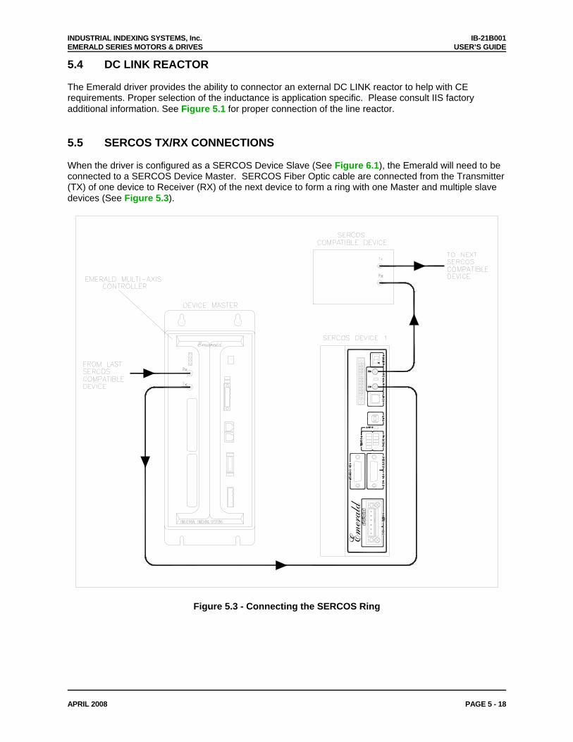
5.4 DC LINK REACTOR The Emerald driver provides the ability to connector an external DC LINK reactor to help with CE requirements. Proper selection of the inductance is application specific. Please consult IIS factory additional information. See Figure 5.1 for proper connection of the line reactor. 5.5 SERCOS TX/RX CONNECTIONS When the driver is configured as a SERCOS Device Slave (See Figure 6.1), the Emerald will need to be connected to a SERCOS Device Master. SERCOS Fiber Optic cable are connected from the Transmitter (TX) of one device to Receiver (RX) of the next device to form a ring with one Master and multiple slave devices (See Figure 5.3).
Emerald
Figure 5.3 - Connecting the SERCOS Ring
INDUSTRIAL INDEXING SYSTEMS, Inc. IB-21B001 EMERALD SERIES MOTORS & DRIVES USER’S GUIDE
APRIL 2008 PAGE 5 - 19
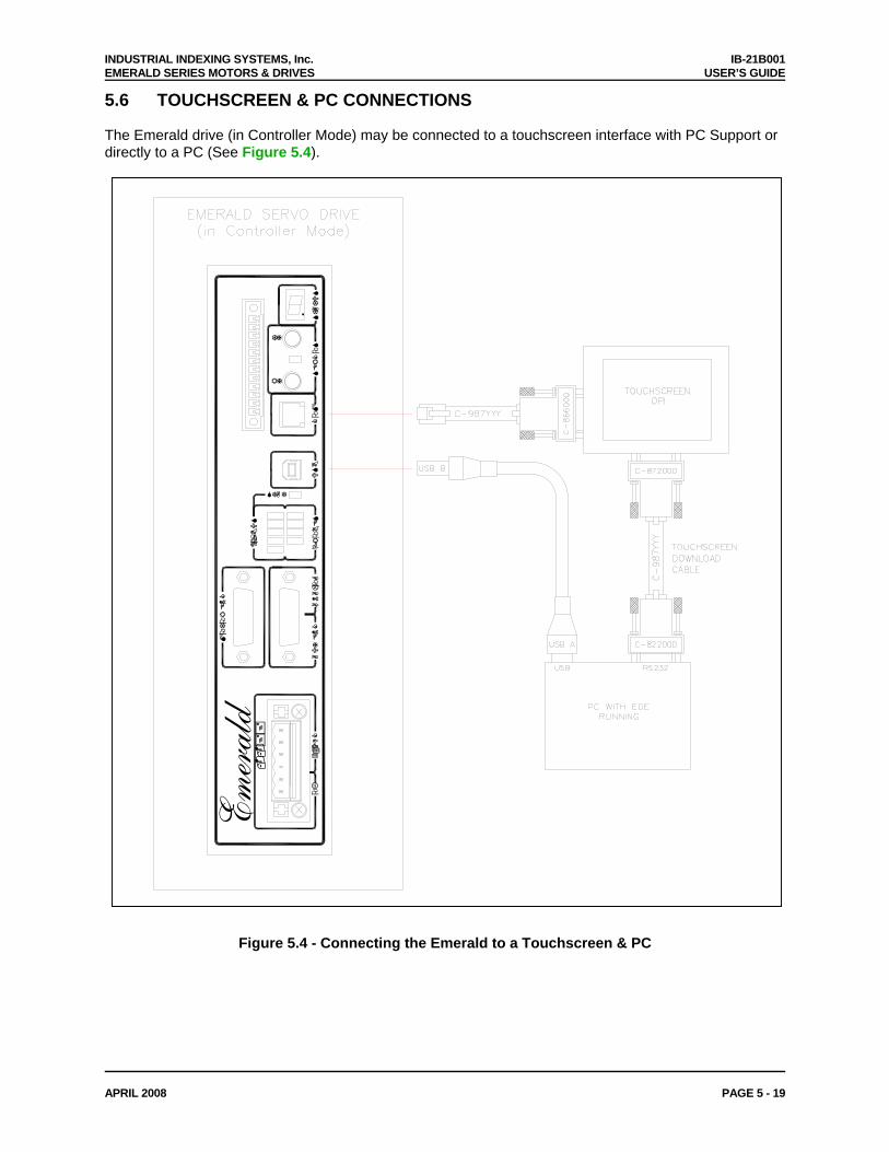
5.6 TOUCHSCREEN & PC CONNECTIONS
The Emerald drive (in Controller Mode) may be connected to a touchscreen interface with PC Support or directly to a PC (See Figure 5.4).
Emerald
Figure 5.4 - Connecting the Emerald to a Touchscreen & PC

INDUSTRIAL INDEXING SYSTEMS, Inc. IB-21B001 EMERALD SERIES MOTORS & DRIVES USER’S GUIDE
APRIL 2008 PAGE 6 - 1
SECTION 6 - CONFIGURATION & PROGRAMMING This section gives information on the Operation Data and Procedure Commands that can be transmitted over the SERCOS Communication ring, over RS-232, or over USB. It also details the settings needed in order to communicate to the drive over the SERCOS ring. 6.1 CONFIGURATION SWITCH The eight DIP switches on top of the Emerald Drive are used to set the SERCOS device address and fiber optic transmitter intensity, in SERCOS mode. Turning all of the switches on will put the drive in CONTROLLER mode (See Figure 6.1). A Device ID of Zero will put the Device in repeater mode and it will not recognize commands over SERCOS. Switches 7 and 8 set the transmitter power. The table below lists the possible settings.
Figure 6.1 - Configuration Switch Settings
SERCOS Transmitter Power
SERCOS Device ID
OFF
ON
SW1-SW6 SERCOS Address 000000 0 100000 1 010000 2
--- --- 011111 62
SETTING SW7 SW8
TX POWERLEVEL
LENGTH OF TRANSMISSION
LINE 0 0 1 0-15 m 1 0 2 15-30 m 0 1 3 30-45 m 1 1 4 >45 m
Note: Turning all of the switches ON will configure the drive in CONTROLLER Mode (SW1-SW8). Then connect the controller directly to the PC running EDE Software.
1 2 3 4 5 6 7 8
INDUSTRIAL INDEXING SYSTEMS, Inc. IB-21B001 EMERALD SERIES MOTORS & DRIVES USER’S GUIDE
APRIL 2008 PAGE 6 - 2
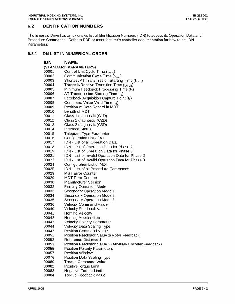
6.2 IDENTIFICATION NUMBERS The Emerald Drive has an extensive list of Identification Numbers (IDN) to access its Operation Data and Procedure Commands. Refer to EDE or manufacturer’s controller documentation for how to set IDN Parameters. 6.2.1 IDN LIST IN NUMERICAL ORDER
IDN NAME (STANDARD PARAMETERS) 00001 Control Unit Cycle Time (tNcyc) 00002 Communication Cycle Time (tScyc) 00003 Shortest AT Transmission Starting Time (t1min) 00004 Transmit/Receive Transition Time (tATMT) 00005 Minimum Feedback Processing Time (t5) 00006 AT Transmission Starting Time (t1) 00007 Feedback Acquisition Capture Point (t4) 00008 Command Value Valid Time (t3) 00009 Position of Data Record in MDT 00010 Length of MDT 00011 Class 1 diagnostic (C1D) 00012 Class 2 diagnostic (C2D) 00013 Class 3 diagnostic (C3D) 00014 Interface Status 00015 Telegram Type Parameter 00016 Configuration List of AT 00017 IDN - List of all Operation Data 00018 IDN - List of Operation Data for Phase 2 00019 IDN - List of Operation Data for Phase 3 00021 IDN - List of Invalid Operation Data for Phase 2 00022 IDN - List of Invalid Operation Data for Phase 3 00024 Configuration List of MDT 00025 IDN - List of all Procedure Commands 00028 MST Error Counter 00029 MDT Error Counter 00030 Manufacturer Version 00032 Primary Operation Mode 00033 Secondary Operation Mode 1 00034 Secondary Operation Mode 2 00035 Secondary Operation Mode 3 00036 Velocity Command Value 00040 Velocity Feedback Value 00041 Homing Velocity 00042 Homing Acceleration 00043 Velocity Polarity Parameter 00044 Velocity Data Scaling Type 00047 Position Command Value 00051 Position Feedback Value 1(Motor Feedback) 00052 Reference Distance 1 00053 Position Feedback Value 2 (Auxiliary Encoder Feedback) 00055 Position Polarity Parameters 00057 Position Window 00076 Position Data Scaling Type 00080 Torque Command Value 00082 PositiveTorque Limit 00083 Negative Torque Limit 00084 Torque Feedback Value
INDUSTRIAL INDEXING SYSTEMS, Inc. IB-21B001 EMERALD SERIES MOTORS & DRIVES USER’S GUIDE
APRIL 2008 PAGE 6 - 3
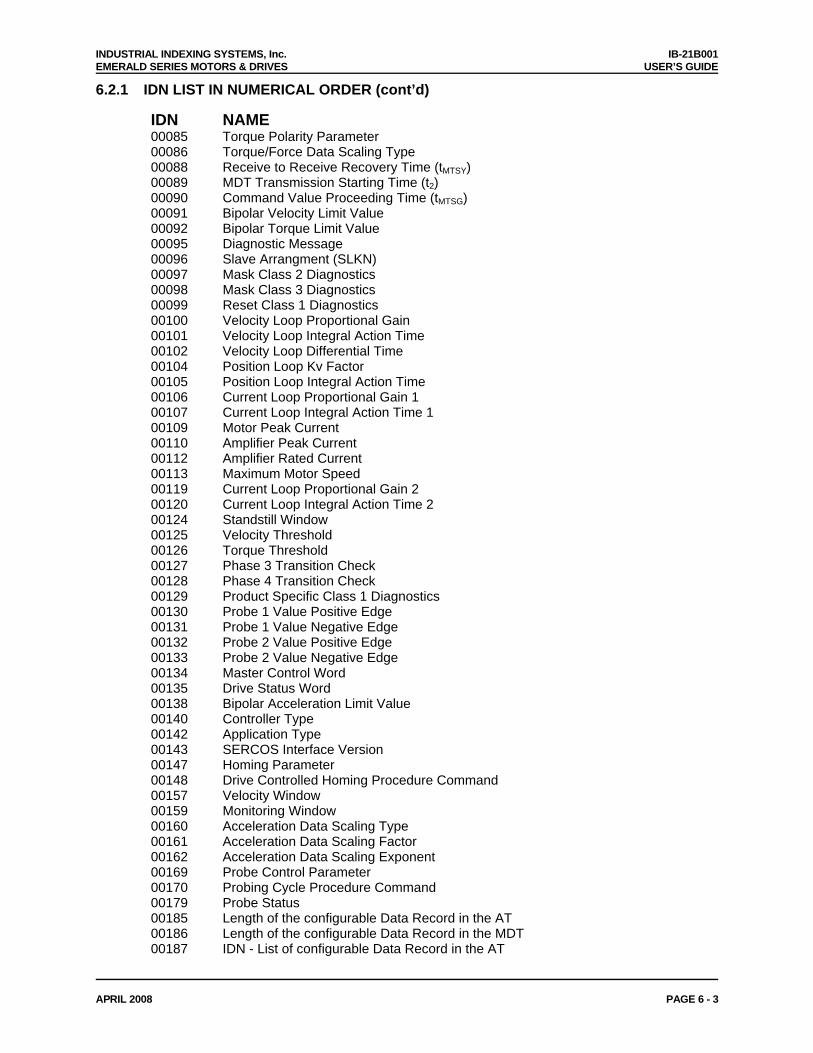
6.2.1 IDN LIST IN NUMERICAL ORDER (cont’d)
IDN NAME 00085 Torque Polarity Parameter 00086 Torque/Force Data Scaling Type 00088 Receive to Receive Recovery Time (tMTSY) 00089 MDT Transmission Starting Time (t2) 00090 Command Value Proceeding Time (tMTSG) 00091 Bipolar Velocity Limit Value 00092 Bipolar Torque Limit Value 00095 Diagnostic Message 00096 Slave Arrangment (SLKN) 00097 Mask Class 2 Diagnostics 00098 Mask Class 3 Diagnostics 00099 Reset Class 1 Diagnostics 00100 Velocity Loop Proportional Gain 00101 Velocity Loop Integral Action Time 00102 Velocity Loop Differential Time 00104 Position Loop Kv Factor 00105 Position Loop Integral Action Time 00106 Current Loop Proportional Gain 1 00107 Current Loop Integral Action Time 1 00109 Motor Peak Current 00110 Amplifier Peak Current 00112 Amplifier Rated Current 00113 Maximum Motor Speed 00119 Current Loop Proportional Gain 2 00120 Current Loop Integral Action Time 2 00124 Standstill Window 00125 Velocity Threshold 00126 Torque Threshold 00127 Phase 3 Transition Check 00128 Phase 4 Transition Check 00129 Product Specific Class 1 Diagnostics 00130 Probe 1 Value Positive Edge 00131 Probe 1 Value Negative Edge 00132 Probe 2 Value Positive Edge 00133 Probe 2 Value Negative Edge 00134 Master Control Word 00135 Drive Status Word 00138 Bipolar Acceleration Limit Value 00140 Controller Type 00142 Application Type 00143 SERCOS Interface Version 00147 Homing Parameter 00148 Drive Controlled Homing Procedure Command 00157 Velocity Window 00159 Monitoring Window 00160 Acceleration Data Scaling Type 00161 Acceleration Data Scaling Factor 00162 Acceleration Data Scaling Exponent 00169 Probe Control Parameter 00170 Probing Cycle Procedure Command 00179 Probe Status 00185 Length of the configurable Data Record in the AT 00186 Length of the configurable Data Record in the MDT 00187 IDN - List of configurable Data Record in the AT
INDUSTRIAL INDEXING SYSTEMS, Inc. IB-21B001 EMERALD SERIES MOTORS & DRIVES USER’S GUIDE
APRIL 2008 PAGE 6 - 4
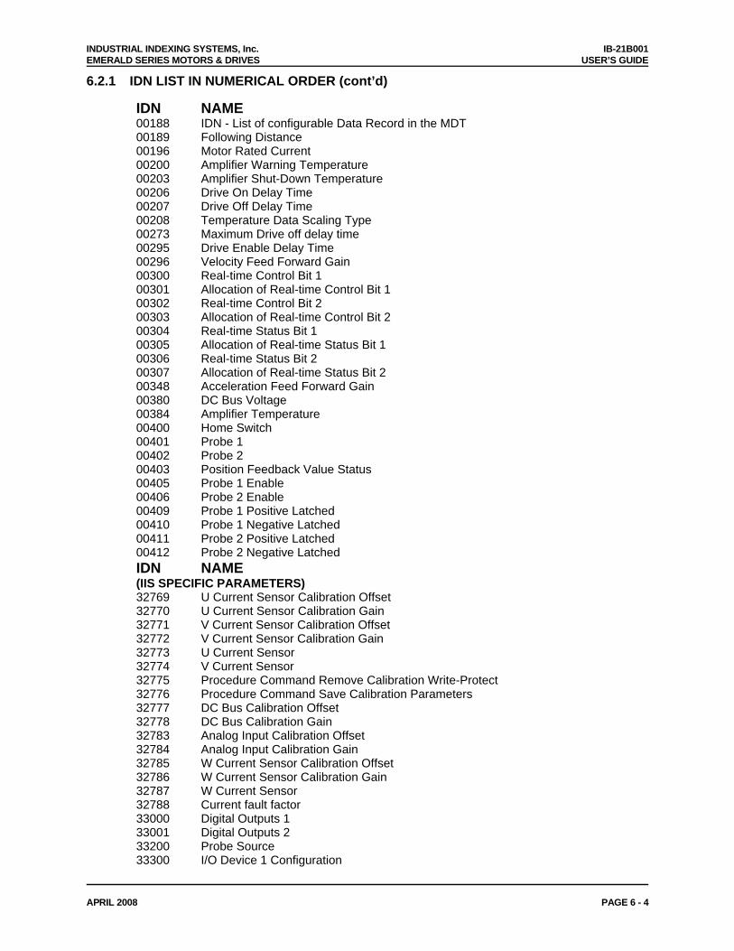
6.2.1 IDN LIST IN NUMERICAL ORDER (cont’d)
IDN NAME 00188 IDN - List of configurable Data Record in the MDT 00189 Following Distance 00196 Motor Rated Current 00200 Amplifier Warning Temperature 00203 Amplifier Shut-Down Temperature 00206 Drive On Delay Time 00207 Drive Off Delay Time 00208 Temperature Data Scaling Type 00273 Maximum Drive off delay time 00295 Drive Enable Delay Time 00296 Velocity Feed Forward Gain 00300 Real-time Control Bit 1 00301 Allocation of Real-time Control Bit 1 00302 Real-time Control Bit 2 00303 Allocation of Real-time Control Bit 2 00304 Real-time Status Bit 1 00305 Allocation of Real-time Status Bit 1 00306 Real-time Status Bit 2 00307 Allocation of Real-time Status Bit 2 00348 Acceleration Feed Forward Gain 00380 DC Bus Voltage 00384 Amplifier Temperature 00400 Home Switch 00401 Probe 1 00402 Probe 2 00403 Position Feedback Value Status 00405 Probe 1 Enable 00406 Probe 2 Enable 00409 Probe 1 Positive Latched 00410 Probe 1 Negative Latched 00411 Probe 2 Positive Latched 00412 Probe 2 Negative Latched IDN NAME (IIS SPECIFIC PARAMETERS) 32769 U Current Sensor Calibration Offset 32770 U Current Sensor Calibration Gain 32771 V Current Sensor Calibration Offset 32772 V Current Sensor Calibration Gain 32773 U Current Sensor 32774 V Current Sensor 32775 Procedure Command Remove Calibration Write-Protect 32776 Procedure Command Save Calibration Parameters 32777 DC Bus Calibration Offset 32778 DC Bus Calibration Gain 32783 Analog Input Calibration Offset 32784 Analog Input Calibration Gain 32785 W Current Sensor Calibration Offset 32786 W Current Sensor Calibration Gain 32787 W Current Sensor 32788 Current fault factor 33000 Digital Outputs 1 33001 Digital Outputs 2 33200 Probe Source 33300 I/O Device 1 Configuration
INDUSTRIAL INDEXING SYSTEMS, Inc. IB-21B001 EMERALD SERIES MOTORS & DRIVES USER’S GUIDE
APRIL 2008 PAGE 6 - 5
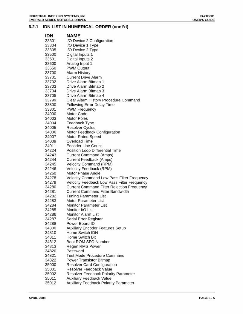
6.2.1 IDN LIST IN NUMERICAL ORDER (cont’d)
IDN NAME 33301 I/O Device 2 Configuration 33304 I/O Device 1 Type 33305 I/O Device 2 Type 33500 Digital Inputs 1 33501 Digital Inputs 2 33600 Analog Input 1 33650 PWM Output 33700 Alarm History 33701 Current Drive Alarm 33702 Drive Alarm Bitmap 1 33703 Drive Alarm Bitmap 2 33704 Drive Alarm Bitmap 3 33705 Drive Alarm Bitmap 4 33799 Clear Alarm History Procedure Command 33800 Following Error Delay Time 33801 PWM Frequency 34000 Motor Code 34003 Motor Poles 34004 Feedback Type 34005 Resolver Cycles 34006 Motor Feedback Configuration 34007 Motor Rated Speed 34009 Overload Time 34011 Encoder Line Count 34224 Position Loop Differential Time 34243 Current Command (Amps) 34244 Current Feedback (Amps) 34245 Velocity Command (RPM) 34246 Velocity Feedback (RPM) 34260 Motor Phase Angle 34278 Velocity Command Low Pass Filter Frequency 34279 Velocity Feedback Low Pass Filter Frequency 34280 Current Command Filter Rejection Frequency 34281 Current Command Filter Bandwidth 34282 Tuning Parameter List 34283 Motor Parameter List 34284 Monitor Parameter List 34285 Monitor I/O List 34286 Monitor Alarm List 34287 Serial Error Register 34288 Power Board ID 34300 Auxiliary Encoder Features Setup 34810 Home Switch IDN 34811 Home Switch Bit 34812 Boot ROM SFO Number 34813 Regen RMS Power 34820 Password 34821 Test Mode Procedure Command 34822 Power Transistor Bitmap 35000 Resolver Card Configuration 35001 Resolver Feedback Value 35002 Resolver Feedback Polarity Parameter 35011 Auxiliary Feedback Value 35012 Auxiliary Feedback Polarity Parameter
INDUSTRIAL INDEXING SYSTEMS, Inc. IB-21B001 EMERALD SERIES MOTORS & DRIVES USER’S GUIDE
APRIL 2008 PAGE 6 - 6
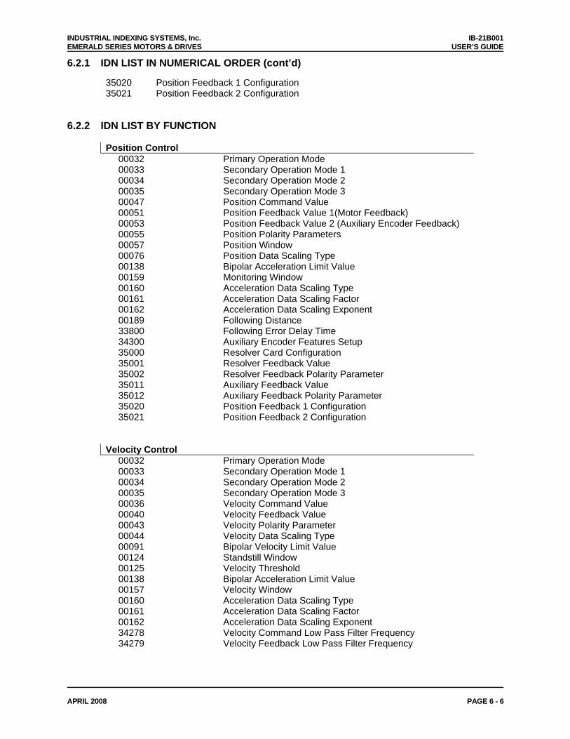
6.2.1 IDN LIST IN NUMERICAL ORDER (cont’d)
35020 Position Feedback 1 Configuration 35021 Position Feedback 2 Configuration
6.2.2 IDN LIST BY FUNCTION
Position Control 00032 Primary Operation Mode 00033 Secondary Operation Mode 1 00034 Secondary Operation Mode 2 00035 Secondary Operation Mode 3 00047 Position Command Value 00051 Position Feedback Value 1(Motor Feedback) 00053 Position Feedback Value 2 (Auxiliary Encoder Feedback) 00055 Position Polarity Parameters 00057 Position Window 00076 Position Data Scaling Type 00138 Bipolar Acceleration Limit Value 00159 Monitoring Window 00160 Acceleration Data Scaling Type 00161 Acceleration Data Scaling Factor 00162 Acceleration Data Scaling Exponent 00189 Following Distance 33800 Following Error Delay Time 34300 Auxiliary Encoder Features Setup 35000 Resolver Card Configuration 35001 Resolver Feedback Value 35002 Resolver Feedback Polarity Parameter 35011 Auxiliary Feedback Value 35012 Auxiliary Feedback Polarity Parameter 35020 Position Feedback 1 Configuration 35021 Position Feedback 2 Configuration Velocity Control 00032 Primary Operation Mode 00033 Secondary Operation Mode 1 00034 Secondary Operation Mode 2 00035 Secondary Operation Mode 3 00036 Velocity Command Value 00040 Velocity Feedback Value 00043 Velocity Polarity Parameter 00044 Velocity Data Scaling Type 00091 Bipolar Velocity Limit Value 00124 Standstill Window 00125 Velocity Threshold 00138 Bipolar Acceleration Limit Value 00157 Velocity Window 00160 Acceleration Data Scaling Type 00161 Acceleration Data Scaling Factor 00162 Acceleration Data Scaling Exponent 34278 Velocity Command Low Pass Filter Frequency 34279 Velocity Feedback Low Pass Filter Frequency
INDUSTRIAL INDEXING SYSTEMS, Inc. IB-21B001 EMERALD SERIES MOTORS & DRIVES USER’S GUIDE
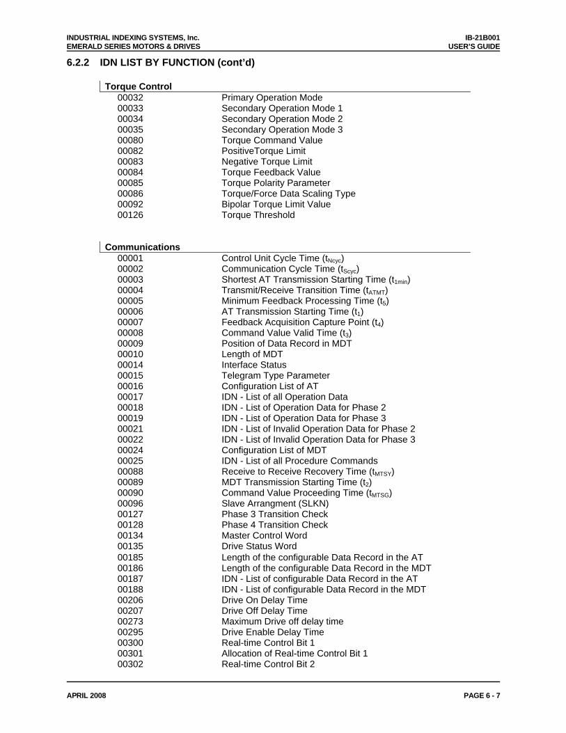
APRIL 2008 PAGE 6 - 7
6.2.2 IDN LIST BY FUNCTION (cont’d)
Torque Control 00032 Primary Operation Mode 00033 Secondary Operation Mode 1 00034 Secondary Operation Mode 2 00035 Secondary Operation Mode 3 00080 Torque Command Value 00082 PositiveTorque Limit 00083 Negative Torque Limit 00084 Torque Feedback Value 00085 Torque Polarity Parameter 00086 Torque/Force Data Scaling Type 00092 Bipolar Torque Limit Value 00126 Torque Threshold Communications 00001 Control Unit Cycle Time (tNcyc) 00002 Communication Cycle Time (tScyc) 00003 Shortest AT Transmission Starting Time (t1min) 00004 Transmit/Receive Transition Time (tATMT) 00005 Minimum Feedback Processing Time (t5) 00006 AT Transmission Starting Time (t1) 00007 Feedback Acquisition Capture Point (t4) 00008 Command Value Valid Time (t3) 00009 Position of Data Record in MDT 00010 Length of MDT 00014 Interface Status 00015 Telegram Type Parameter 00016 Configuration List of AT 00017 IDN - List of all Operation Data 00018 IDN - List of Operation Data for Phase 2 00019 IDN - List of Operation Data for Phase 3 00021 IDN - List of Invalid Operation Data for Phase 2 00022 IDN - List of Invalid Operation Data for Phase 3 00024 Configuration List of MDT 00025 IDN - List of all Procedure Commands 00088 Receive to Receive Recovery Time (tMTSY) 00089 MDT Transmission Starting Time (t2) 00090 Command Value Proceeding Time (tMTSG) 00096 Slave Arrangment (SLKN) 00127 Phase 3 Transition Check 00128 Phase 4 Transition Check 00134 Master Control Word 00135 Drive Status Word 00185 Length of the configurable Data Record in the AT 00186 Length of the configurable Data Record in the MDT 00187 IDN - List of configurable Data Record in the AT 00188 IDN - List of configurable Data Record in the MDT 00206 Drive On Delay Time 00207 Drive Off Delay Time 00273 Maximum Drive off delay time 00295 Drive Enable Delay Time 00300 Real-time Control Bit 1 00301 Allocation of Real-time Control Bit 1 00302 Real-time Control Bit 2
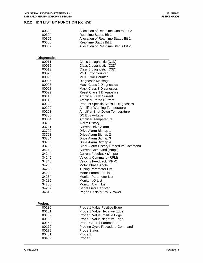
INDUSTRIAL INDEXING SYSTEMS, Inc. IB-21B001 EMERALD SERIES MOTORS & DRIVES USER’S GUIDE
APRIL 2008 PAGE 6 - 8
6.2.2 IDN LIST BY FUNCTION (cont’d)
00303 Allocation of Real-time Control Bit 2 00304 Real-time Status Bit 1 00305 Allocation of Real-time Status Bit 1 00306 Real-time Status Bit 2 00307 Allocation of Real-time Status Bit 2 Diagnostics 00011 Class 1 diagnostic (C1D) 00012 Class 2 diagnostic (C2D) 00013 Class 3 diagnostic (C3D) 00028 MST Error Counter 00029 MDT Error Counter 00095 Diagnostic Message 00097 Mask Class 2 Diagnostics 00098 Mask Class 3 Diagnostics 00099 Reset Class 1 Diagnostics 00110 Amplifier Peak Current 00112 Amplifier Rated Current 00129 Product Specific Class 1 Diagnostics 00200 Amplifier Warning Temperature 00203 Amplifier Shut-Down Temperature 00380 DC Bus Voltage 00384 Amplifier Temperature 33700 Alarm History 33701 Current Drive Alarm 33702 Drive Alarm Bitmap 1 33703 Drive Alarm Bitmap 2 33704 Drive Alarm Bitmap 3 33705 Drive Alarm Bitmap 4 33799 Clear Alarm History Procedure Command 34243 Current Command (Amps) 34244 Current Feedback (Amps) 34245 Velocity Command (RPM) 34246 Velocity Feedback (RPM) 34260 Motor Phase Angle 34282 Tuning Parameter List 34283 Motor Parameter List 34284 Monitor Parameter List 34285 Monitor I/O List 34286 Monitor Alarm List 34287 Serial Error Register 34813 Regen Resistor RMS Power Probes 00130 Probe 1 Value Positive Edge 00131 Probe 1 Value Negative Edge 00132 Probe 2 Value Positive Edge 00133 Probe 2 Value Negative Edge 00169 Probe Control Parameter 00170 Probing Cycle Procedure Command 00179 Probe Status 00401 Probe 1 00402 Probe 2
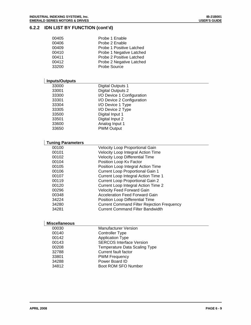
INDUSTRIAL INDEXING SYSTEMS, Inc. IB-21B001 EMERALD SERIES MOTORS & DRIVES USER’S GUIDE
APRIL 2008 PAGE 6 - 9
6.2.2 IDN LIST BY FUNCTION (cont’d)
00405 Probe 1 Enable 00406 Probe 2 Enable 00409 Probe 1 Positive Latched 00410 Probe 1 Negative Latched 00411 Probe 2 Positive Latched 00412 Probe 2 Negative Latched 33200 Probe Source Inputs/Outputs 33000 Digital Outputs 1 33001 Digital Outputs 2 33300 I/O Device 1 Configuration 33301 I/O Device 2 Configuration 33304 I/O Device 1 Type 33305 I/O Device 2 Type 33500 Digital Input 1 33501 Digital Input 2 33600 Analog Input 1 33650 PWM Output Tuning Parameters 00100 Velocity Loop Proportional Gain 00101 Velocity Loop Integral Action Time 00102 Velocity Loop Differential Time 00104 Position Loop Kv Factor 00105 Position Loop Integral Action Time 00106 Current Loop Proportional Gain 1 00107 Current Loop Integral Action Time 1 00119 Current Loop Proportional Gain 2 00120 Current Loop Integral Action Time 2 00296 Velocity Feed Forward Gain 00348 Acceleration Feed Forward Gain 34224 Position Loop Differential Time 34280 Current Command Filter Rejection Frequency 34281 Current Command Filter Bandwidth Miscellaneous 00030 Manufacturer Version 00140 Controller Type 00142 Application Type 00143 SERCOS Interface Version 00208 Temperature Data Scaling Type 32788 Current fault factor 33801 PWM Frequency 34288 Power Board ID 34812 Boot ROM SFO Number
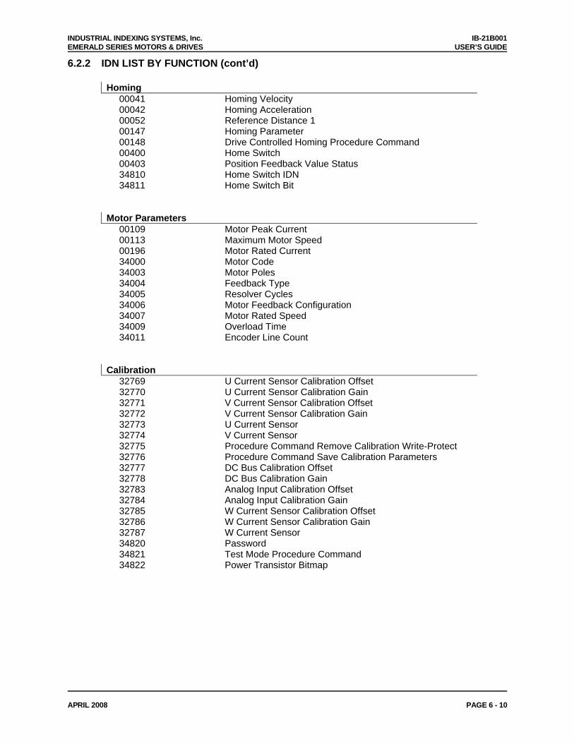
INDUSTRIAL INDEXING SYSTEMS, Inc. IB-21B001 EMERALD SERIES MOTORS & DRIVES USER’S GUIDE
APRIL 2008 PAGE 6 - 10
6.2.2 IDN LIST BY FUNCTION (cont’d)
Homing 00041 Homing Velocity 00042 Homing Acceleration 00052 Reference Distance 1 00147 Homing Parameter 00148 Drive Controlled Homing Procedure Command 00400 Home Switch 00403 Position Feedback Value Status 34810 Home Switch IDN 34811 Home Switch Bit Motor Parameters 00109 Motor Peak Current 00113 Maximum Motor Speed 00196 Motor Rated Current 34000 Motor Code 34003 Motor Poles 34004 Feedback Type 34005 Resolver Cycles 34006 Motor Feedback Configuration 34007 Motor Rated Speed 34009 Overload Time 34011 Encoder Line Count Calibration 32769 U Current Sensor Calibration Offset 32770 U Current Sensor Calibration Gain 32771 V Current Sensor Calibration Offset 32772 V Current Sensor Calibration Gain 32773 U Current Sensor 32774 V Current Sensor 32775 Procedure Command Remove Calibration Write-Protect 32776 Procedure Command Save Calibration Parameters 32777 DC Bus Calibration Offset 32778 DC Bus Calibration Gain 32783 Analog Input Calibration Offset 32784 Analog Input Calibration Gain 32785 W Current Sensor Calibration Offset 32786 W Current Sensor Calibration Gain 32787 W Current Sensor 34820 Password 34821 Test Mode Procedure Command 34822 Power Transistor Bitmap
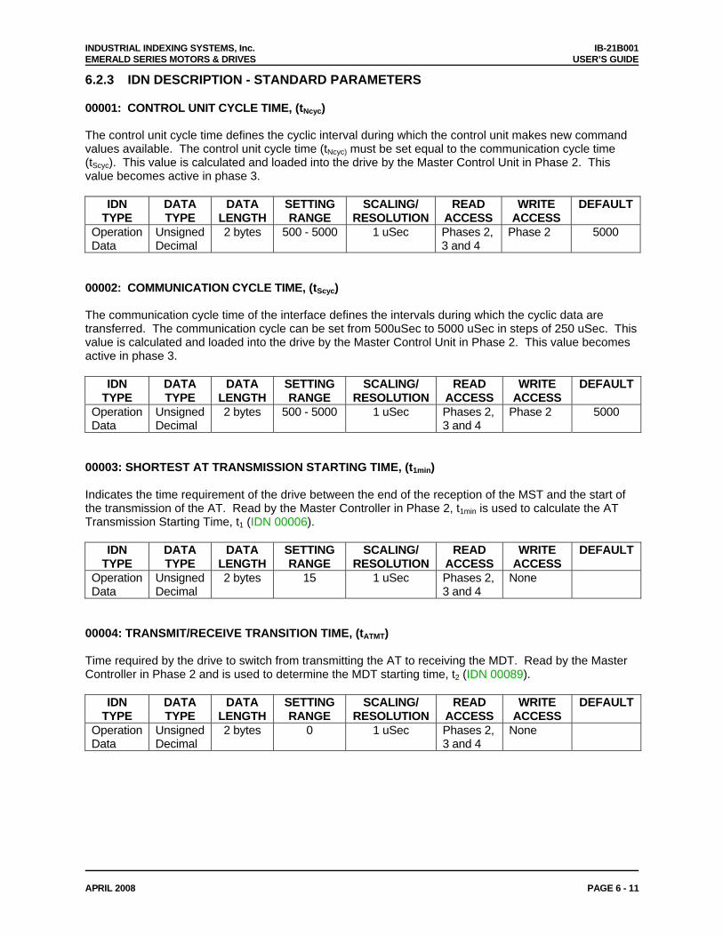
INDUSTRIAL INDEXING SYSTEMS, Inc. IB-21B001 EMERALD SERIES MOTORS & DRIVES USER’S GUIDE
APRIL 2008 PAGE 6 - 11
6.2.3 IDN DESCRIPTION - STANDARD PARAMETERS 00001: CONTROL UNIT CYCLE TIME, (tNcyc) The control unit cycle time defines the cyclic interval during which the control unit makes new command values available. The control unit cycle time (tNcyc) must be set equal to the communication cycle time (tScyc). This value is calculated and loaded into the drive by the Master Control Unit in Phase 2. This value becomes active in phase 3.
IDN TYPE
DATA TYPE
DATA LENGTH
SETTING RANGE
SCALING/ RESOLUTION
READ ACCESS
WRITE ACCESS
DEFAULT
Operation Data
Unsigned Decimal
2 bytes 500 - 5000 1 uSec Phases 2, 3 and 4
Phase 2 5000
00002: COMMUNICATION CYCLE TIME, (tScyc) The communication cycle time of the interface defines the intervals during which the cyclic data are transferred. The communication cycle can be set from 500uSec to 5000 uSec in steps of 250 uSec. This value is calculated and loaded into the drive by the Master Control Unit in Phase 2. This value becomes active in phase 3.
IDN TYPE
DATA TYPE
DATA LENGTH
SETTING RANGE
SCALING/ RESOLUTION
READ ACCESS
WRITE ACCESS
DEFAULT
Operation Data
Unsigned Decimal
2 bytes 500 - 5000 1 uSec Phases 2, 3 and 4
Phase 2 5000
00003: SHORTEST AT TRANSMISSION STARTING TIME, (t1min) Indicates the time requirement of the drive between the end of the reception of the MST and the start of the transmission of the AT. Read by the Master Controller in Phase 2, t1min is used to calculate the AT Transmission Starting Time, t1 (IDN 00006).
IDN TYPE
DATA TYPE
DATA LENGTH
SETTING RANGE
SCALING/ RESOLUTION
READ ACCESS
WRITE ACCESS
DEFAULT
Operation Data
Unsigned Decimal
2 bytes 15 1 uSec Phases 2, 3 and 4
None
00004: TRANSMIT/RECEIVE TRANSITION TIME, (tATMT) Time required by the drive to switch from transmitting the AT to receiving the MDT. Read by the Master Controller in Phase 2 and is used to determine the MDT starting time, t2 (IDN 00089).
IDN TYPE
DATA TYPE
DATA LENGTH
SETTING RANGE
SCALING/ RESOLUTION
READ ACCESS
WRITE ACCESS
DEFAULT
Operation Data
Unsigned Decimal
2 bytes 0 1 uSec Phases 2, 3 and 4
None
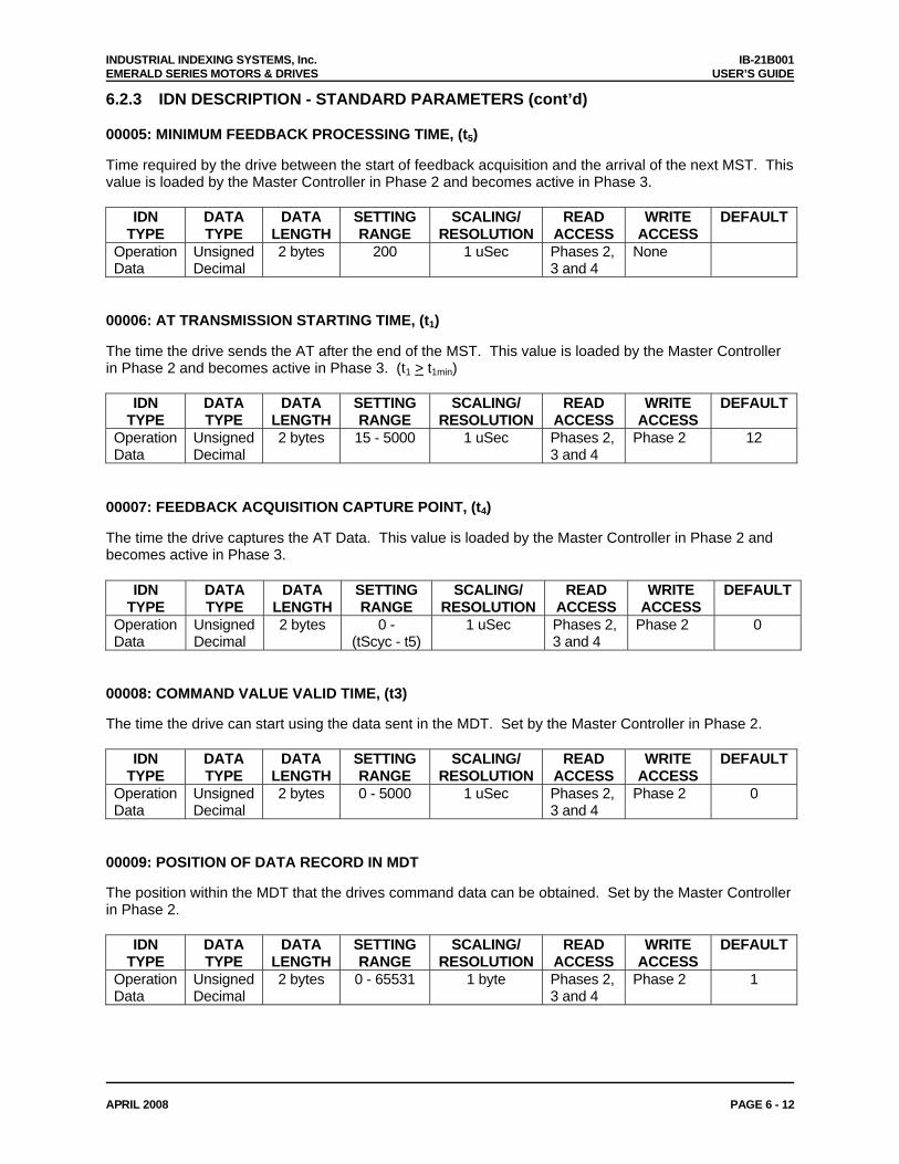
INDUSTRIAL INDEXING SYSTEMS, Inc. IB-21B001 EMERALD SERIES MOTORS & DRIVES USER’S GUIDE
APRIL 2008 PAGE 6 - 12
6.2.3 IDN DESCRIPTION - STANDARD PARAMETERS (cont’d) 00005: MINIMUM FEEDBACK PROCESSING TIME, (t5) Time required by the drive between the start of feedback acquisition and the arrival of the next MST. This value is loaded by the Master Controller in Phase 2 and becomes active in Phase 3.
IDN TYPE
DATA TYPE
DATA LENGTH
SETTING RANGE
SCALING/ RESOLUTION
READ ACCESS
WRITE ACCESS
DEFAULT
Operation Data
Unsigned Decimal
2 bytes 200 1 uSec Phases 2, 3 and 4
None
00006: AT TRANSMISSION STARTING TIME, (t1) The time the drive sends the AT after the end of the MST. This value is loaded by the Master Controller in Phase 2 and becomes active in Phase 3. (t1 > t1min)
IDN TYPE
DATA TYPE
DATA LENGTH
SETTING RANGE
SCALING/ RESOLUTION
READ ACCESS
WRITE ACCESS
DEFAULT
Operation Data
Unsigned Decimal
2 bytes 15 - 5000 1 uSec Phases 2, 3 and 4
Phase 2 12
00007: FEEDBACK ACQUISITION CAPTURE POINT, (t4) The time the drive captures the AT Data. This value is loaded by the Master Controller in Phase 2 and becomes active in Phase 3.
IDN TYPE
DATA TYPE
DATA LENGTH
SETTING RANGE
SCALING/ RESOLUTION
READ ACCESS
WRITE ACCESS
DEFAULT
Operation Data
Unsigned Decimal
2 bytes 0 - (tScyc - t5)
1 uSec Phases 2, 3 and 4
Phase 2 0
00008: COMMAND VALUE VALID TIME, (t3) The time the drive can start using the data sent in the MDT. Set by the Master Controller in Phase 2.
IDN TYPE
DATA TYPE
DATA LENGTH
SETTING RANGE
SCALING/ RESOLUTION
READ ACCESS
WRITE ACCESS
DEFAULT
Operation Data
Unsigned Decimal
2 bytes 0 - 5000 1 uSec Phases 2, 3 and 4
Phase 2 0
00009: POSITION OF DATA RECORD IN MDT The position within the MDT that the drives command data can be obtained. Set by the Master Controller in Phase 2.
IDN TYPE
DATA TYPE
DATA LENGTH
SETTING RANGE
SCALING/ RESOLUTION
READ ACCESS
WRITE ACCESS
DEFAULT
Operation Data
Unsigned Decimal
2 bytes 0 - 65531 1 byte Phases 2, 3 and 4
Phase 2 1
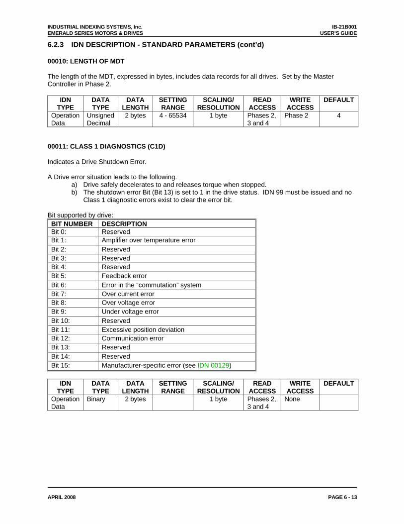
INDUSTRIAL INDEXING SYSTEMS, Inc. IB-21B001 EMERALD SERIES MOTORS & DRIVES USER’S GUIDE
APRIL 2008 PAGE 6 - 13
6.2.3 IDN DESCRIPTION - STANDARD PARAMETERS (cont’d) 00010: LENGTH OF MDT The length of the MDT, expressed in bytes, includes data records for all drives. Set by the Master Controller in Phase 2.
IDN TYPE
DATA TYPE
DATA LENGTH
SETTING RANGE
SCALING/ RESOLUTION
READ ACCESS
WRITE ACCESS
DEFAULT
Operation Data
Unsigned Decimal
2 bytes 4 - 65534 1 byte Phases 2, 3 and 4
Phase 2 4
00011: CLASS 1 DIAGNOSTICS (C1D) Indicates a Drive Shutdown Error. A Drive error situation leads to the following.
a) Drive safely decelerates to and releases torque when stopped. b) The shutdown error Bit (Bit 13) is set to 1 in the drive status. IDN 99 must be issued and no
Class 1 diagnostic errors exist to clear the error bit. Bit supported by drive: BIT NUMBER DESCRIPTION Bit 0: Reserved Bit 1: Amplifier over temperature error Bit 2: Reserved Bit 3: Reserved Bit 4: Reserved Bit 5: Feedback error Bit 6: Error in the “commutation” system Bit 7: Over current error Bit 8: Over voltage error Bit 9: Under voltage error Bit 10: Reserved Bit 11: Excessive position deviation Bit 12: Communication error Bit 13: Reserved Bit 14: Reserved Bit 15: Manufacturer-specific error (see IDN 00129)
IDN
TYPE DATA TYPE
DATA LENGTH
SETTING RANGE
SCALING/ RESOLUTION
READ ACCESS
WRITE ACCESS
DEFAULT
Operation Data
Binary 2 bytes 1 byte Phases 2, 3 and 4
None
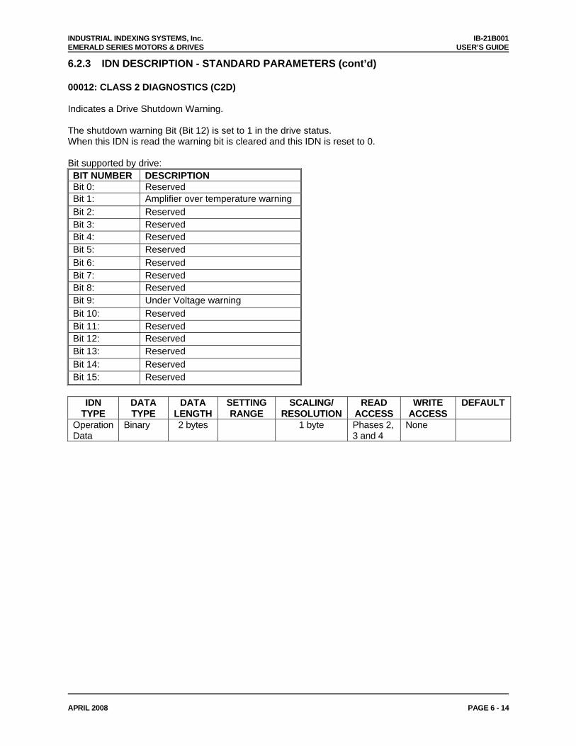
INDUSTRIAL INDEXING SYSTEMS, Inc. IB-21B001 EMERALD SERIES MOTORS & DRIVES USER’S GUIDE
APRIL 2008 PAGE 6 - 14
6.2.3 IDN DESCRIPTION - STANDARD PARAMETERS (cont’d) 00012: CLASS 2 DIAGNOSTICS (C2D) Indicates a Drive Shutdown Warning. The shutdown warning Bit (Bit 12) is set to 1 in the drive status. When this IDN is read the warning bit is cleared and this IDN is reset to 0. Bit supported by drive: BIT NUMBER DESCRIPTION Bit 0: Reserved Bit 1: Amplifier over temperature warning Bit 2: Reserved Bit 3: Reserved Bit 4: Reserved Bit 5: Reserved Bit 6: Reserved Bit 7: Reserved Bit 8: Reserved Bit 9: Under Voltage warning Bit 10: Reserved Bit 11: Reserved Bit 12: Reserved Bit 13: Reserved Bit 14: Reserved Bit 15: Reserved
IDN
TYPE DATA TYPE
DATA LENGTH
SETTING RANGE
SCALING/ RESOLUTION
READ ACCESS
WRITE ACCESS
DEFAULT
Operation Data
Binary 2 bytes 1 byte Phases 2, 3 and 4
None
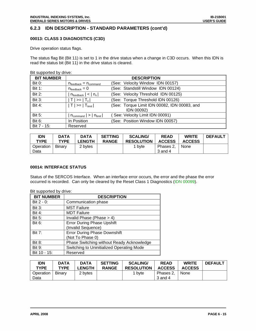
INDUSTRIAL INDEXING SYSTEMS, Inc. IB-21B001 EMERALD SERIES MOTORS & DRIVES USER’S GUIDE
APRIL 2008 PAGE 6 - 15
6.2.3 IDN DESCRIPTION - STANDARD PARAMETERS (cont’d) 00013: CLASS 3 DIAGNOSTICS (C3D) Drive operation status flags. The status flag Bit (Bit 11) is set to 1 in the drive status when a change in C3D occurs. When this IDN is read the status bit (Bit 11) in the drive status is cleared. Bit supported by drive:
BIT NUMBER DESCRIPTION Bit 0: nfeedback = ncommand (See: Velocity Window IDN 00157) Bit 1: nfeedback = 0 (See: Standstill Window IDN 00124) Bit 2: | nfeedback | < | nx | (See: Velocity Threshold IDN 00125) Bit 3: | T | >= | Tx | (See: Torque Threshold IDN 00126) Bit 4: | T | >= | Tlimit | (See: Torque Limit IDN 00082, IDN 00083, and
IDN 00092) Bit 5: | ncommand | > | nlimit | ( See: Velocity Limit IDN 00091) Bit 6: In Position (See: Position Window IDN 00057) Bit 7 - 15: Reserved
IDN
TYPE DATA TYPE
DATA LENGTH
SETTING RANGE
SCALING/ RESOLUTION
READ ACCESS
WRITE ACCESS
DEFAULT
Operation Data
Binary 2 bytes 1 byte Phases 2, 3 and 4
None
00014: INTERFACE STATUS Status of the SERCOS Interface. When an interface error occurs, the error and the phase the error occurred is recorded. Can only be cleared by the Reset Class 1 Diagnostics (IDN 00099). Bit supported by drive:
BIT NUMBER DESCRIPTION Bit 2 - 0: Communication phase Bit 3: MST Failure Bit 4: MDT Failure Bit 5: Invalid Phase (Phase > 4) Bit 6: Error During Phase Upshift
(Invalid Sequence) Bit 7: Error During Phase Downshift
(Not To Phase 0) Bit 8: Phase Switching without Ready Acknowledge Bit 9: Switching to Uninitialized Operating Mode Bit 10 - 15: Reserved
IDN
TYPE DATA TYPE
DATA LENGTH
SETTING RANGE
SCALING/ RESOLUTION
READ ACCESS
WRITE ACCESS
DEFAULT
Operation Data
Binary 2 bytes 1 byte Phases 2, 3 and 4
None
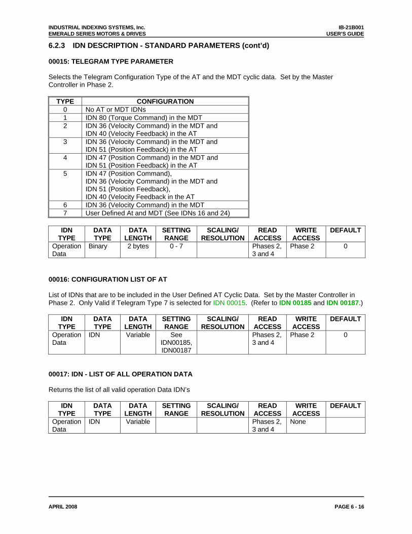
INDUSTRIAL INDEXING SYSTEMS, Inc. IB-21B001 EMERALD SERIES MOTORS & DRIVES USER’S GUIDE
APRIL 2008 PAGE 6 - 16
6.2.3 IDN DESCRIPTION - STANDARD PARAMETERS (cont’d) 00015: TELEGRAM TYPE PARAMETER Selects the Telegram Configuration Type of the AT and the MDT cyclic data. Set by the Master Controller in Phase 2.
TYPE CONFIGURATION 0 No AT or MDT IDNs 1 IDN 80 (Torque Command) in the MDT 2 IDN 36 (Velocity Command) in the MDT and
IDN 40 (Velocity Feedback) in the AT 3 IDN 36 (Velocity Command) in the MDT and
IDN 51 (Position Feedback) in the AT 4 IDN 47 (Position Command) in the MDT and
IDN 51 (Position Feedback) in the AT 5 IDN 47 (Position Command),
IDN 36 (Velocity Command) in the MDT and IDN 51 (Position Feedback), IDN 40 (Velocity Feedback in the AT
6 IDN 36 (Velocity Command) in the MDT 7 User Defined At and MDT (See IDNs 16 and 24)
IDN
TYPE DATA TYPE
DATA LENGTH
SETTING RANGE
SCALING/ RESOLUTION
READ ACCESS
WRITE ACCESS
DEFAULT
Operation Data
Binary 2 bytes 0 - 7 Phases 2, 3 and 4
Phase 2 0
00016: CONFIGURATION LIST OF AT List of IDNs that are to be included in the User Defined AT Cyclic Data. Set by the Master Controller in Phase 2. Only Valid if Telegram Type 7 is selected for IDN 00015. (Refer to IDN 00185 and IDN 00187.)
IDN TYPE
DATA TYPE
DATA LENGTH
SETTING RANGE
SCALING/ RESOLUTION
READ ACCESS
WRITE ACCESS
DEFAULT
Operation Data
IDN Variable See IDN00185, IDN00187
Phases 2, 3 and 4
Phase 2 0
00017: IDN - LIST OF ALL OPERATION DATA Returns the list of all valid operation Data IDN’s
IDN TYPE
DATA TYPE
DATA LENGTH
SETTING RANGE
SCALING/ RESOLUTION
READ ACCESS
WRITE ACCESS
DEFAULT
Operation Data
IDN Variable Phases 2, 3 and 4
None
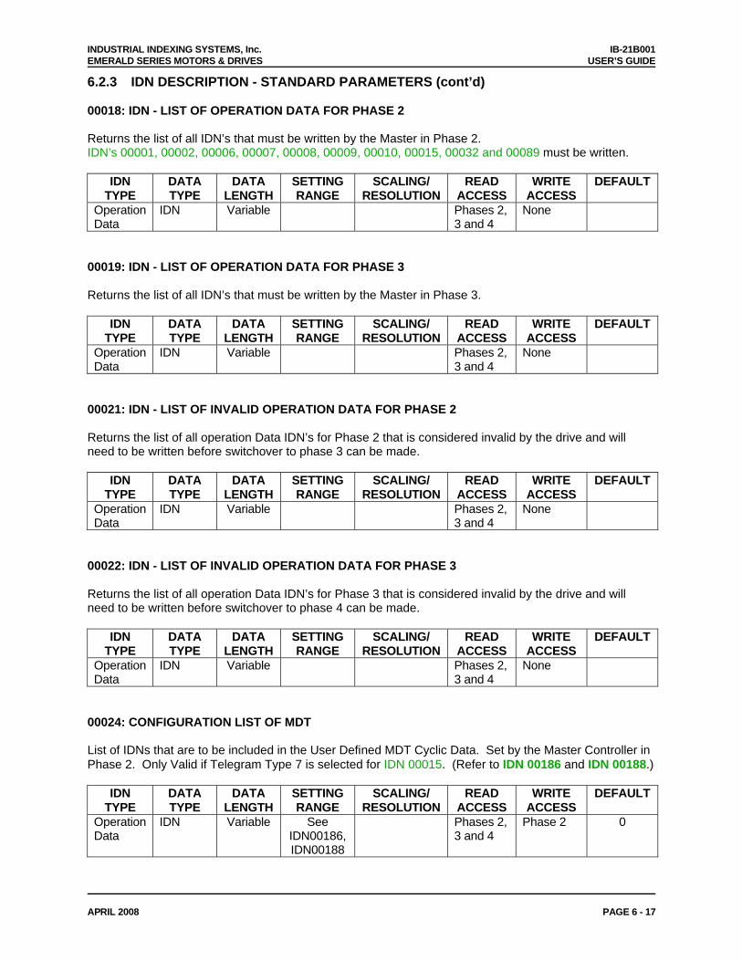
INDUSTRIAL INDEXING SYSTEMS, Inc. IB-21B001 EMERALD SERIES MOTORS & DRIVES USER’S GUIDE
APRIL 2008 PAGE 6 - 17
6.2.3 IDN DESCRIPTION - STANDARD PARAMETERS (cont’d) 00018: IDN - LIST OF OPERATION DATA FOR PHASE 2 Returns the list of all IDN’s that must be written by the Master in Phase 2. IDN’s 00001, 00002, 00006, 00007, 00008, 00009, 00010, 00015, 00032 and 00089 must be written.
IDN TYPE
DATA TYPE
DATA LENGTH
SETTING RANGE
SCALING/ RESOLUTION
READ ACCESS
WRITE ACCESS
DEFAULT
Operation Data
IDN Variable Phases 2, 3 and 4
None
00019: IDN - LIST OF OPERATION DATA FOR PHASE 3 Returns the list of all IDN’s that must be written by the Master in Phase 3.
IDN TYPE
DATA TYPE
DATA LENGTH
SETTING RANGE
SCALING/ RESOLUTION
READ ACCESS
WRITE ACCESS
DEFAULT
Operation Data
IDN Variable Phases 2, 3 and 4
None
00021: IDN - LIST OF INVALID OPERATION DATA FOR PHASE 2 Returns the list of all operation Data IDN’s for Phase 2 that is considered invalid by the drive and will need to be written before switchover to phase 3 can be made.
IDN TYPE
DATA TYPE
DATA LENGTH
SETTING RANGE
SCALING/ RESOLUTION
READ ACCESS
WRITE ACCESS
DEFAULT
Operation Data
IDN Variable Phases 2, 3 and 4
None
00022: IDN - LIST OF INVALID OPERATION DATA FOR PHASE 3 Returns the list of all operation Data IDN’s for Phase 3 that is considered invalid by the drive and will need to be written before switchover to phase 4 can be made.
IDN TYPE
DATA TYPE
DATA LENGTH
SETTING RANGE
SCALING/ RESOLUTION
READ ACCESS
WRITE ACCESS
DEFAULT
Operation Data
IDN Variable Phases 2, 3 and 4
None
00024: CONFIGURATION LIST OF MDT List of IDNs that are to be included in the User Defined MDT Cyclic Data. Set by the Master Controller in Phase 2. Only Valid if Telegram Type 7 is selected for IDN 00015. (Refer to IDN 00186 and IDN 00188.)
IDN TYPE
DATA TYPE
DATA LENGTH
SETTING RANGE
SCALING/ RESOLUTION
READ ACCESS
WRITE ACCESS
DEFAULT
Operation Data
IDN Variable See IDN00186, IDN00188
Phases 2, 3 and 4
Phase 2 0
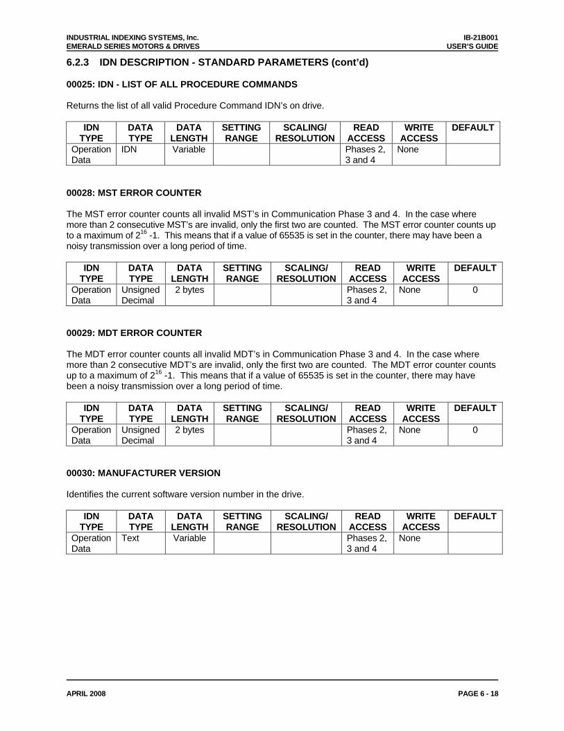
INDUSTRIAL INDEXING SYSTEMS, Inc. IB-21B001 EMERALD SERIES MOTORS & DRIVES USER’S GUIDE
APRIL 2008 PAGE 6 - 18
6.2.3 IDN DESCRIPTION - STANDARD PARAMETERS (cont’d) 00025: IDN - LIST OF ALL PROCEDURE COMMANDS Returns the list of all valid Procedure Command IDN’s on drive.
IDN TYPE
DATA TYPE
DATA LENGTH
SETTING RANGE
SCALING/ RESOLUTION
READ ACCESS
WRITE ACCESS
DEFAULT
Operation Data
IDN Variable Phases 2, 3 and 4
None
00028: MST ERROR COUNTER The MST error counter counts all invalid MST’s in Communication Phase 3 and 4. In the case where more than 2 consecutive MST’s are invalid, only the first two are counted. The MST error counter counts up to a maximum of 216 -1. This means that if a value of 65535 is set in the counter, there may have been a noisy transmission over a long period of time.
IDN TYPE
DATA TYPE
DATA LENGTH
SETTING RANGE
SCALING/ RESOLUTION
READ ACCESS
WRITE ACCESS
DEFAULT
Operation Data
Unsigned Decimal
2 bytes Phases 2, 3 and 4
None 0
00029: MDT ERROR COUNTER The MDT error counter counts all invalid MDT’s in Communication Phase 3 and 4. In the case where more than 2 consecutive MDT’s are invalid, only the first two are counted. The MDT error counter counts up to a maximum of 216 -1. This means that if a value of 65535 is set in the counter, there may have been a noisy transmission over a long period of time.
IDN TYPE
DATA TYPE
DATA LENGTH
SETTING RANGE
SCALING/ RESOLUTION
READ ACCESS
WRITE ACCESS
DEFAULT
Operation Data
Unsigned Decimal
2 bytes Phases 2, 3 and 4
None 0
00030: MANUFACTURER VERSION Identifies the current software version number in the drive.
IDN TYPE
DATA TYPE
DATA LENGTH
SETTING RANGE
SCALING/ RESOLUTION
READ ACCESS
WRITE ACCESS
DEFAULT
Operation Data
Text Variable Phases 2, 3 and 4
None
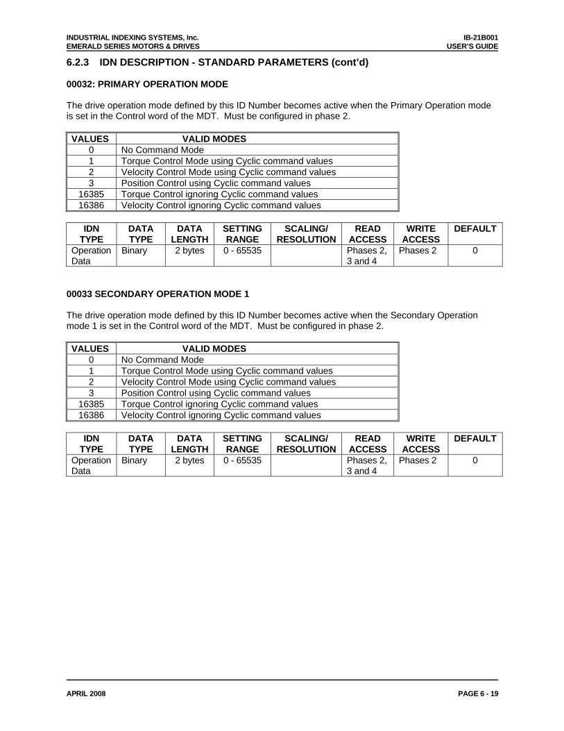
INDUSTRIAL INDEXING SYSTEMS, Inc. IB-21B001 EMERALD SERIES MOTORS & DRIVES USER’S GUIDE
APRIL 2008 PAGE 6 - 19
6.2.3 IDN DESCRIPTION - STANDARD PARAMETERS (cont’d) 00032: PRIMARY OPERATION MODE The drive operation mode defined by this ID Number becomes active when the Primary Operation mode is set in the Control word of the MDT. Must be configured in phase 2. VALUES VALID MODES
0 No Command Mode 1 Torque Control Mode using Cyclic command values 2 Velocity Control Mode using Cyclic command values 3 Position Control using Cyclic command values
16385 Torque Control ignoring Cyclic command values 16386 Velocity Control ignoring Cyclic command values
IDN
TYPE DATA TYPE
DATA LENGTH
SETTING RANGE
SCALING/ RESOLUTION
READ ACCESS
WRITE ACCESS
DEFAULT
Operation Data
Binary 2 bytes 0 - 65535 Phases 2, 3 and 4
Phases 2 0
00033 SECONDARY OPERATION MODE 1 The drive operation mode defined by this ID Number becomes active when the Secondary Operation mode 1 is set in the Control word of the MDT. Must be configured in phase 2. VALUES VALID MODES
0 No Command Mode 1 Torque Control Mode using Cyclic command values 2 Velocity Control Mode using Cyclic command values 3 Position Control using Cyclic command values
16385 Torque Control ignoring Cyclic command values 16386 Velocity Control ignoring Cyclic command values
IDN
TYPE DATA TYPE
DATA LENGTH
SETTING RANGE
SCALING/ RESOLUTION
READ ACCESS
WRITE ACCESS
DEFAULT
Operation Data
Binary 2 bytes 0 - 65535 Phases 2, 3 and 4
Phases 2 0
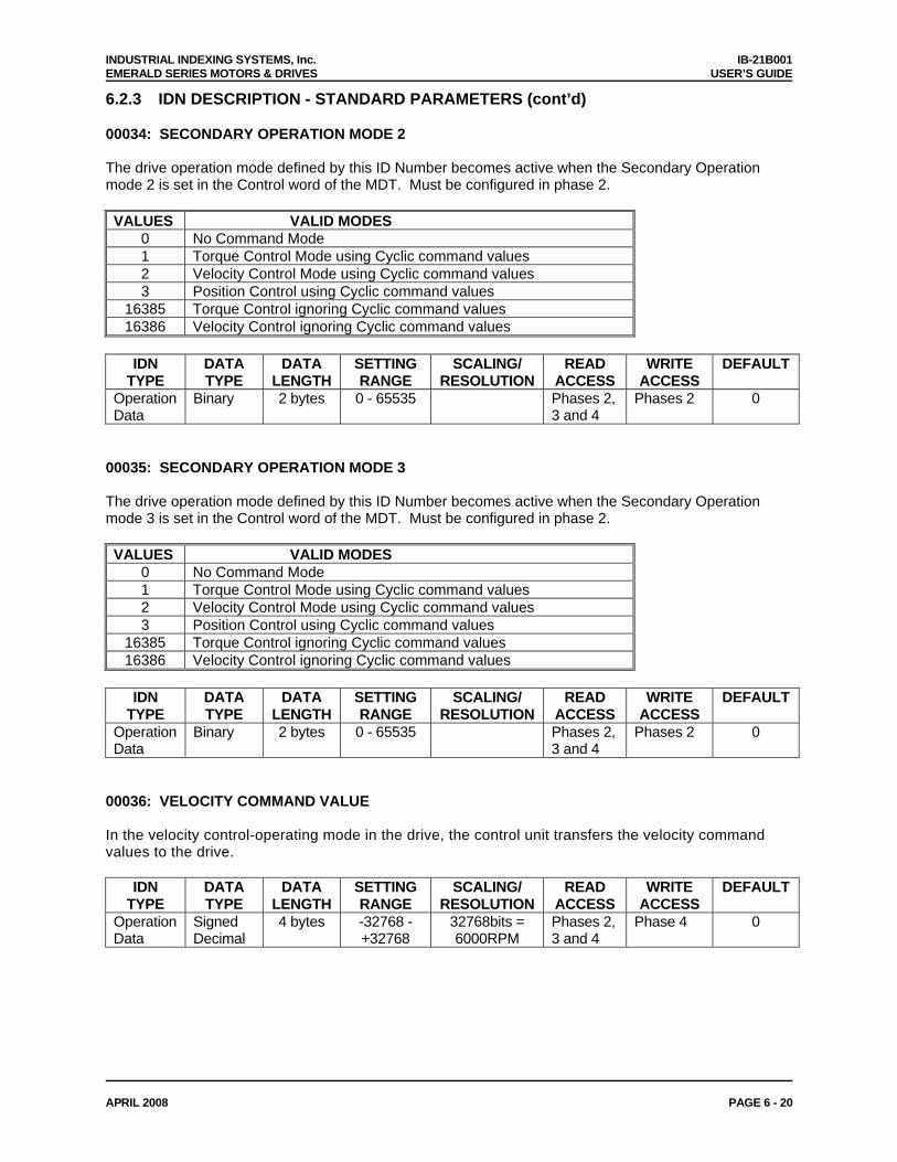
INDUSTRIAL INDEXING SYSTEMS, Inc. IB-21B001 EMERALD SERIES MOTORS & DRIVES USER’S GUIDE
APRIL 2008 PAGE 6 - 20
6.2.3 IDN DESCRIPTION - STANDARD PARAMETERS (cont’d) 00034: SECONDARY OPERATION MODE 2 The drive operation mode defined by this ID Number becomes active when the Secondary Operation mode 2 is set in the Control word of the MDT. Must be configured in phase 2. VALUES VALID MODES
0 No Command Mode 1 Torque Control Mode using Cyclic command values 2 Velocity Control Mode using Cyclic command values 3 Position Control using Cyclic command values
16385 Torque Control ignoring Cyclic command values 16386 Velocity Control ignoring Cyclic command values
IDN
TYPE DATA TYPE
DATA LENGTH
SETTING RANGE
SCALING/ RESOLUTION
READ ACCESS
WRITE ACCESS
DEFAULT
Operation Data
Binary 2 bytes 0 - 65535 Phases 2, 3 and 4
Phases 2 0
00035: SECONDARY OPERATION MODE 3 The drive operation mode defined by this ID Number becomes active when the Secondary Operation mode 3 is set in the Control word of the MDT. Must be configured in phase 2. VALUES VALID MODES
0 No Command Mode 1 Torque Control Mode using Cyclic command values 2 Velocity Control Mode using Cyclic command values 3 Position Control using Cyclic command values
16385 Torque Control ignoring Cyclic command values 16386 Velocity Control ignoring Cyclic command values
IDN
TYPE DATA TYPE
DATA LENGTH
SETTING RANGE
SCALING/ RESOLUTION
READ ACCESS
WRITE ACCESS
DEFAULT
Operation Data
Binary 2 bytes 0 - 65535 Phases 2, 3 and 4
Phases 2 0
00036: VELOCITY COMMAND VALUE In the velocity control-operating mode in the drive, the control unit transfers the velocity command values to the drive.
IDN TYPE
DATA TYPE
DATA LENGTH
SETTING RANGE
SCALING/ RESOLUTION
READ ACCESS
WRITE ACCESS
DEFAULT
Operation Data
Signed Decimal
4 bytes -32768 - +32768
32768bits = 6000RPM
Phases 2, 3 and 4
Phase 4 0
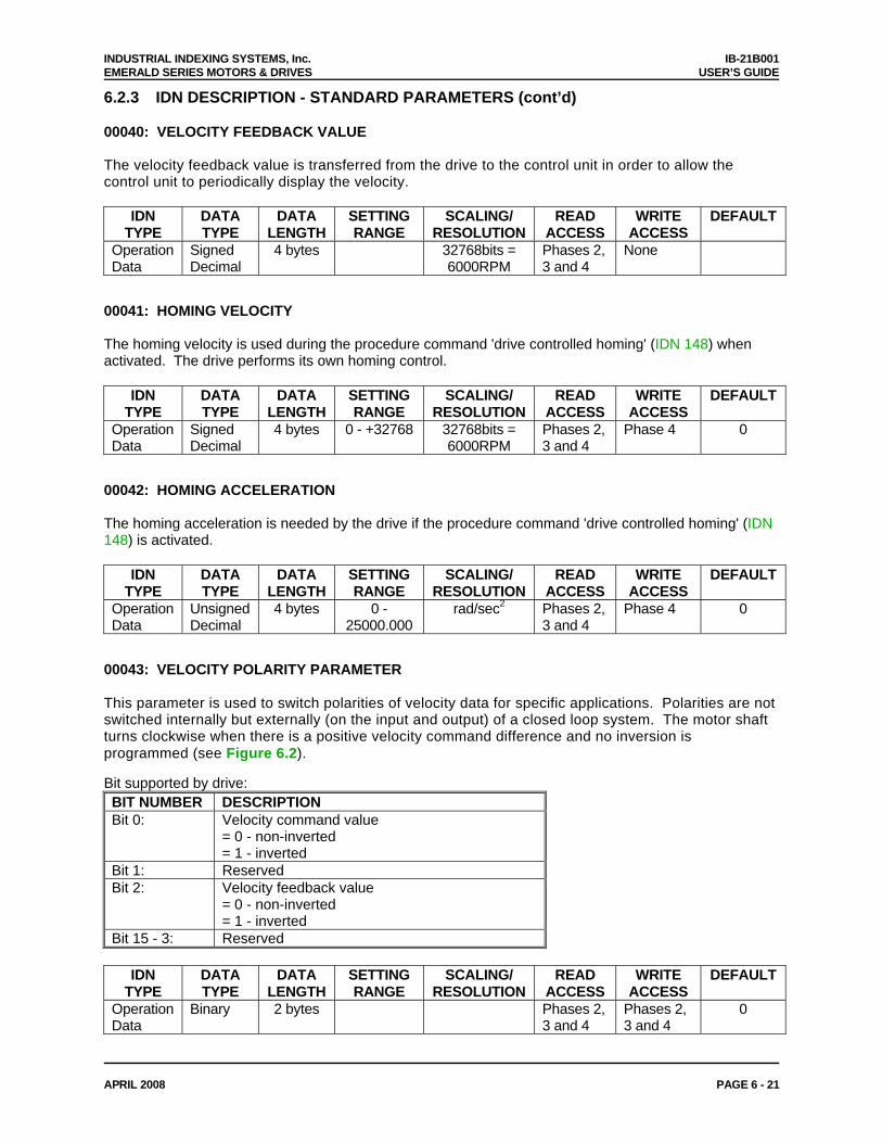
INDUSTRIAL INDEXING SYSTEMS, Inc. IB-21B001 EMERALD SERIES MOTORS & DRIVES USER’S GUIDE
APRIL 2008 PAGE 6 - 21
6.2.3 IDN DESCRIPTION - STANDARD PARAMETERS (cont’d) 00040: VELOCITY FEEDBACK VALUE The velocity feedback value is transferred from the drive to the control unit in order to allow the control unit to periodically display the velocity.
IDN TYPE
DATA TYPE
DATA LENGTH
SETTING RANGE
SCALING/ RESOLUTION
READ ACCESS
WRITE ACCESS
DEFAULT
Operation Data
Signed Decimal
4 bytes 32768bits = 6000RPM
Phases 2, 3 and 4
None
00041: HOMING VELOCITY The homing velocity is used during the procedure command 'drive controlled homing' (IDN 148) when activated. The drive performs its own homing control.
IDN TYPE
DATA TYPE
DATA LENGTH
SETTING RANGE
SCALING/ RESOLUTION
READ ACCESS
WRITE ACCESS
DEFAULT
Operation Data
Signed Decimal
4 bytes 0 - +32768 32768bits = 6000RPM
Phases 2, 3 and 4
Phase 4 0
00042: HOMING ACCELERATION The homing acceleration is needed by the drive if the procedure command 'drive controlled homing' (IDN 148) is activated.
IDN TYPE
DATA TYPE
DATA LENGTH
SETTING RANGE
SCALING/ RESOLUTION
READ ACCESS
WRITE ACCESS
DEFAULT
Operation Data
Unsigned Decimal
4 bytes 0 - 25000.000
rad/sec2 Phases 2, 3 and 4
Phase 4 0
00043: VELOCITY POLARITY PARAMETER This parameter is used to switch polarities of velocity data for specific applications. Polarities are not switched internally but externally (on the input and output) of a closed loop system. The motor shaft turns clockwise when there is a positive velocity command difference and no inversion is programmed (see Figure 6.2). Bit supported by drive: BIT NUMBER DESCRIPTION Bit 0: Velocity command value
= 0 - non-inverted = 1 - inverted
Bit 1: Reserved Bit 2: Velocity feedback value
= 0 - non-inverted = 1 - inverted
Bit 15 - 3: Reserved
IDN TYPE
DATA TYPE
DATA LENGTH
SETTING RANGE
SCALING/ RESOLUTION
READ ACCESS
WRITE ACCESS
DEFAULT
Operation Data
Binary 2 bytes Phases 2, 3 and 4
Phases 2, 3 and 4
0
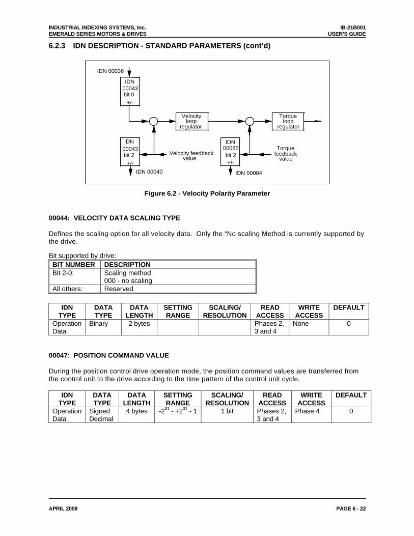
INDUSTRIAL INDEXING SYSTEMS, Inc. IB-21B001 EMERALD SERIES MOTORS & DRIVES USER’S GUIDE
APRIL 2008 PAGE 6 - 22
6.2.3 IDN DESCRIPTION - STANDARD PARAMETERS (cont’d)
Torque loop
regulator
IDN00085bit 2+/-
Torque feedback
value Velocity feedback
IDN 00084
IDN 00036 IDN
00043 bit 0 +/-
Velocityloop
regulator
00043 bit 2 +/-
IDN
value
IDN 00040
Figure 6.2 - Velocity Polarity Parameter
00044: VELOCITY DATA SCALING TYPE Defines the scaling option for all velocity data. Only the “No scaling Method is currently supported by the drive. Bit supported by drive: BIT NUMBER DESCRIPTION Bit 2-0: Scaling method
000 - no scaling All others: Reserved
IDN
TYPE DATA TYPE
DATA LENGTH
SETTING RANGE
SCALING/ RESOLUTION
READ ACCESS
WRITE ACCESS
DEFAULT
Operation Data
Binary 2 bytes Phases 2, 3 and 4
None 0
00047: POSITION COMMAND VALUE During the position control drive operation mode, the position command values are transferred from the control unit to the drive according to the time pattern of the control unit cycle.
IDN TYPE
DATA TYPE
DATA LENGTH
SETTING RANGE
SCALING/ RESOLUTION
READ ACCESS
WRITE ACCESS
DEFAULT
Operation Data
Signed Decimal
4 bytes -231 - +231 - 1 1 bit Phases 2, 3 and 4
Phase 4 0
INDUSTRIAL INDEXING SYSTEMS, Inc. IB-21B001 EMERALD SERIES MOTORS & DRIVES USER’S GUIDE
APRIL 2008 PAGE 6 - 23
6.2.3 IDN DESCRIPTION - STANDARD PARAMETERS (cont’d) 00051: POSITION FEEDBACK VALUE 1 (MOTOR FEEDBACK) The position feedback value 1 is transferred from the drive to the control unit.
IDN TYPE
DATA TYPE
DATA LENGTH
SETTING RANGE
SCALING/ RESOLUTION
READ ACCESS
WRITE ACCESS
DEFAULT
Operation Data
Signed Decimal
4 bytes 1 bit Phases 2, 3 and 4
None
00052: REFERENCE DISTANCE 1 This parameter describes the distance between the machine zero point and the reference point related to the motor feedback. After the homing procedure, the position feedback value 1 is calculated by: - reference distance 1;
IDN TYPE
DATA TYPE
DATA LENGTH
SETTING RANGE
SCALING/ RESOLUTION
READ ACCESS
WRITE ACCESS
DEFAULT
Operation Data
Signed Decimal
4 bytes -231 - +231 - 1 1 bit Phases 2, 3 and 4
Phases 2, 3 and 4
0
00053: POSITION FEEDBACK VALUE 2 The position feedback value 2 is transferred from the drive to the control unit.
IDN TYPE
DATA TYPE
DATA LENGTH
SETTING RANGE
SCALING/ RESOLUTION
READ ACCESS
WRITE ACCESS
DEFAULT
Operation Data
Signed Decimal
4 bytes 1 bit Phases 2, 3 and 4
None
00055: POSITION POLARITY PARAMETERS This parameter is used to switch polarities of reported position data for specific applications. Polarities are switched outside (i.e. on the input and output) of a closed loop system. The motor shaft turns clockwise (when viewed from the output shaft) when there is a positive position command difference and no inversion is programmed (see Figure 6.3). Bit supported by drive: BIT NUMBER DESCRIPTION Bit 0: Position command value
0 - Non-inverted 1 - Inverted
Bit 1: Reserved Bit 2: Position feedback value 1
0 - Non-inverted 1 - Inverted
Bit 3: Position feedback value 2 0 - Non-inverted 1 - Inverted
Bit 4-15: Reserved
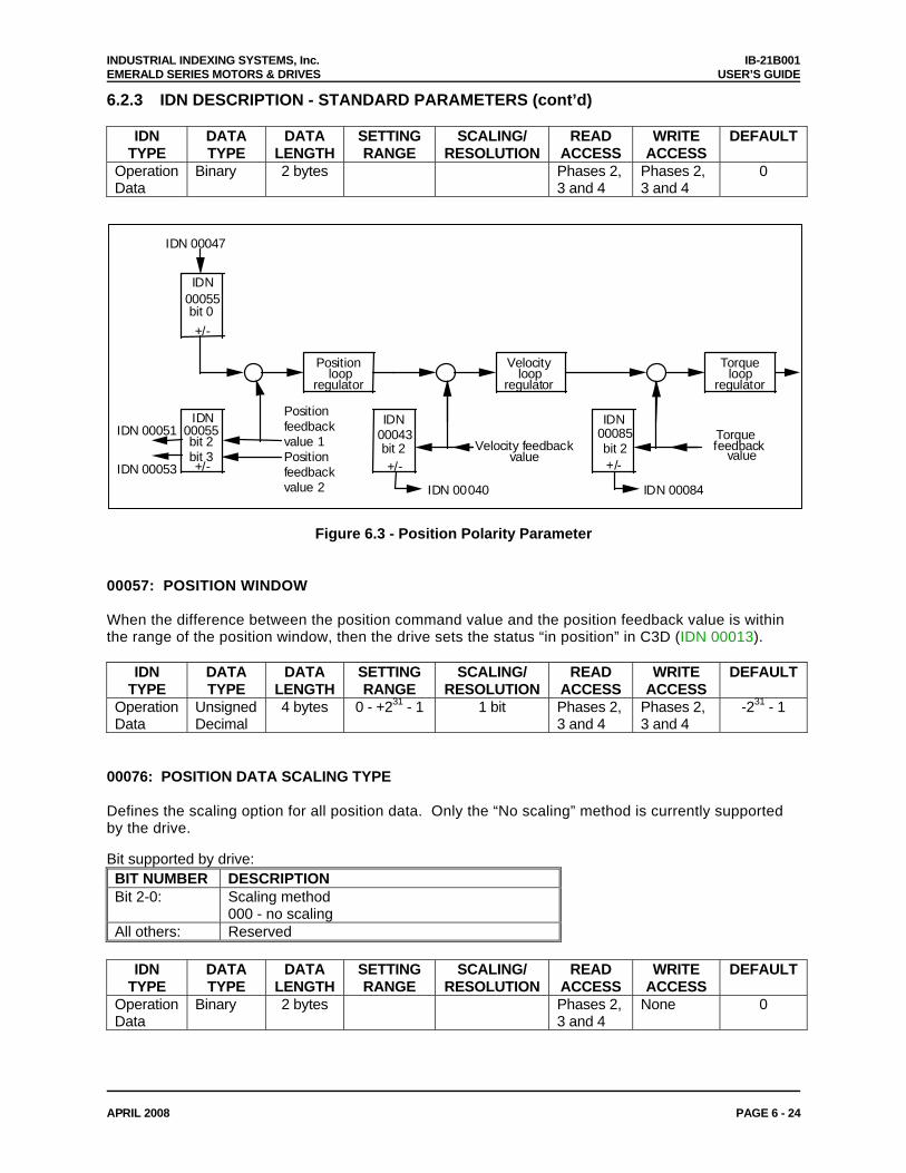
INDUSTRIAL INDEXING SYSTEMS, Inc. IB-21B001 EMERALD SERIES MOTORS & DRIVES USER’S GUIDE
APRIL 2008 PAGE 6 - 24
6.2.3 IDN DESCRIPTION - STANDARD PARAMETERS (cont’d)
IDN TYPE
DATA TYPE
DATA LENGTH
SETTING RANGE
SCALING/ RESOLUTION
READ ACCESS
WRITE ACCESS
DEFAULT
Operation Data
Binary 2 bytes Phases 2, 3 and 4
Phases 2, 3 and 4
0
Torqueloop
regulator
IDN00085bit 2+/-
Torquefeedback
valueVelocity feedback
IDN 00084
Velocityloop
regulator
00043bit 2+/-
IDN
value
IDN 00040
Positionloop
regulator
IDN 00047
IDN00055bit 0+/-
00055bit 2bit 3+/-
IDNIDN 00051
IDN 00053
Positionfeedbackvalue 1Positionfeedbackvalue 2
Figure 6.3 - Position Polarity Parameter 00057: POSITION WINDOW When the difference between the position command value and the position feedback value is within the range of the position window, then the drive sets the status “in position” in C3D (IDN 00013).
IDN TYPE
DATA TYPE
DATA LENGTH
SETTING RANGE
SCALING/ RESOLUTION
READ ACCESS
WRITE ACCESS
DEFAULT
Operation Data
Unsigned Decimal
4 bytes 0 - +231 - 1 1 bit Phases 2, 3 and 4
Phases 2, 3 and 4
-231 - 1
00076: POSITION DATA SCALING TYPE Defines the scaling option for all position data. Only the “No scaling” method is currently supported by the drive. Bit supported by drive: BIT NUMBER DESCRIPTION Bit 2-0: Scaling method
000 - no scaling All others: Reserved
IDN
TYPE DATA TYPE
DATA LENGTH
SETTING RANGE
SCALING/ RESOLUTION
READ ACCESS
WRITE ACCESS
DEFAULT
Operation Data
Binary 2 bytes Phases 2, 3 and 4
None 0
INDUSTRIAL INDEXING SYSTEMS, Inc. IB-21B001 EMERALD SERIES MOTORS & DRIVES USER’S GUIDE
APRIL 2008 PAGE 6 - 25
6.2.3 IDN DESCRIPTION - STANDARD PARAMETERS (cont’d) 00080: TORQUE COMMAND VALUE During the torque control operation mode of the drive, torque command values are transferred from the control unit to the drive. This IDN is scaled as a percentage of the drive or motor’s peak torque, whichever is less.
IDN TYPE
DATA TYPE
DATA LENGTH
SETTING RANGE
SCALING/ RESOLUTION
READ ACCESS
WRITE ACCESS
DEFAULT
Operation Data
Signed Decimal
2 bytes -100.00 - +100.00
0.01% Phases 2, 3 and 4
Phase 4 0
00082: POSITIVE TORQUE LIMIT The positive torque limit value limits the maximum torque in the positive direction. If the torque limit is exceeded, the drive sets the status T >= Tlimit in C3D (IDN 00013).
IDN TYPE
DATA TYPE
DATA LENGTH
SETTING RANGE
SCALING/ RESOLUTION
READ ACCESS
WRITE ACCESS
DEFAULT
Operation Data
Signed Decimal
2 bytes 0.00 - 100.00
0.01% Phases 2, 3 and 4
Phases 2, 3 and 4
100.00
00083: NEGATIVE TORQUE LIMIT The negative torque limit value limits the maximum torque in the negative direction. If the torque limit is exceeded, the drive sets the status T >= Tlimit in C3D (IDN 00013).
IDN TYPE
DATA TYPE
DATA LENGTH
SETTING RANGE
SCALING/ RESOLUTION
READ ACCESS
WRITE ACCESS
DEFAULT
Operation Data
Signed Decimal
2 bytes 0.00 - 100.00
0.01% Phases 2, 3 and 4
Phases 2, 3 and 4
-100.00 ?
00084: TORQUE FEEDBACK VALUE The torque feedback value is transferred from the drive to the control unit. This IDN is scaled as a percentage of the drive or motor’s peak torque, whichever is less.
IDN TYPE
DATA TYPE
DATA LENGTH
SETTING RANGE
SCALING/ RESOLUTION
READ ACCESS
WRITE ACCESS
DEFAULT
Operation Data
Signed Decimal
2 bytes 0.01% Phases 2, 3 and 4
None
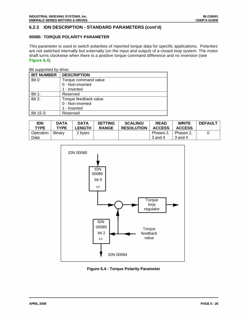
INDUSTRIAL INDEXING SYSTEMS, Inc. IB-21B001 EMERALD SERIES MOTORS & DRIVES USER’S GUIDE
APRIL 2008 PAGE 6 - 26
6.2.3 IDN DESCRIPTION - STANDARD PARAMETERS (cont’d) 00085: TORQUE POLARITY PARAMETER This parameter is used to switch polarities of reported torque data for specific applications. Polarities are not switched internally but externally (on the input and output) of a closed loop system. The motor shaft turns clockwise when there is a positive torque command difference and no inversion (see Figure 6.4). Bit supported by drive: BIT NUMBER DESCRIPTION Bit 0: Torque command value
0 - Non-inverted 1 - Inverted
Bit 1: Reserved Bit 2: Torque feedback value
0 - Non-inverted 1 - Inverted
Bit 15-3: Reserved
IDN TYPE
DATA TYPE
DATA LENGTH
SETTING RANGE
SCALING/ RESOLUTION
READ ACCESS
WRITE ACCESS
DEFAULT
Operation Data
Binary 2 bytes Phases 2, 3 and 4
Phases 2, 3 and 4
0
IDN
00085 bit 0
+/-
Torque loop
regulator
IDN00085 bit 2 +/-
Torque feedback
value
IDN 00084
IDN 00080
Figure 6.4 - Torque Polarity Parameter
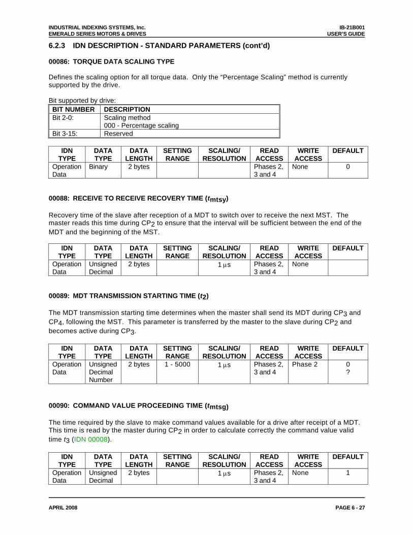
INDUSTRIAL INDEXING SYSTEMS, Inc. IB-21B001 EMERALD SERIES MOTORS & DRIVES USER’S GUIDE
APRIL 2008 PAGE 6 - 27
6.2.3 IDN DESCRIPTION - STANDARD PARAMETERS (cont’d) 00086: TORQUE DATA SCALING TYPE Defines the scaling option for all torque data. Only the “Percentage Scaling” method is currently supported by the drive. Bit supported by drive: BIT NUMBER DESCRIPTION Bit 2-0: Scaling method
000 - Percentage scaling Bit 3-15: Reserved
IDN
TYPE DATA TYPE
DATA LENGTH
SETTING RANGE
SCALING/ RESOLUTION
READ ACCESS
WRITE ACCESS
DEFAULT
Operation Data
Binary 2 bytes Phases 2, 3 and 4
None 0
00088: RECEIVE TO RECEIVE RECOVERY TIME (tmtsy) Recovery time of the slave after reception of a MDT to switch over to receive the next MST. The master reads this time during CP2 to ensure that the interval will be sufficient between the end of the MDT and the beginning of the MST.
IDN TYPE
DATA TYPE
DATA LENGTH
SETTING RANGE
SCALING/ RESOLUTION
READ ACCESS
WRITE ACCESS
DEFAULT
Operation Data
Unsigned Decimal
2 bytes 1 μs Phases 2, 3 and 4
None
00089: MDT TRANSMISSION STARTING TIME (t2) The MDT transmission starting time determines when the master shall send its MDT during CP3 and CP4, following the MST. This parameter is transferred by the master to the slave during CP2 and becomes active during CP3.
IDN TYPE
DATA TYPE
DATA LENGTH
SETTING RANGE
SCALING/ RESOLUTION
READ ACCESS
WRITE ACCESS
DEFAULT
Operation Data
Unsigned Decimal Number
2 bytes 1 - 5000 1 μs Phases 2, 3 and 4
Phase 2 0 ?
00090: COMMAND VALUE PROCEEDING TIME (tmtsg) The time required by the slave to make command values available for a drive after receipt of a MDT. This time is read by the master during CP2 in order to calculate correctly the command value valid time t3 (IDN 00008).
IDN TYPE
DATA TYPE
DATA LENGTH
SETTING RANGE
SCALING/ RESOLUTION
READ ACCESS
WRITE ACCESS
DEFAULT
Operation Data
Unsigned Decimal
2 bytes 1 μs Phases 2, 3 and 4
None 1
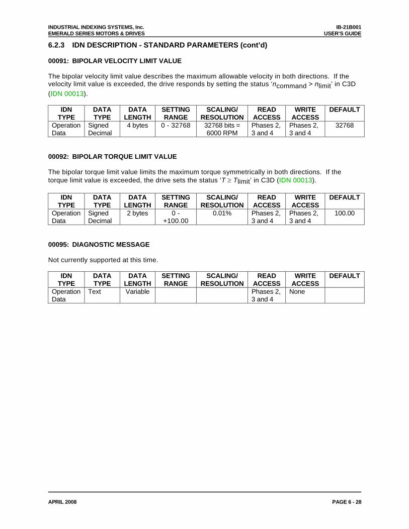
INDUSTRIAL INDEXING SYSTEMS, Inc. IB-21B001 EMERALD SERIES MOTORS & DRIVES USER’S GUIDE
APRIL 2008 PAGE 6 - 28
6.2.3 IDN DESCRIPTION - STANDARD PARAMETERS (cont’d) 00091: BIPOLAR VELOCITY LIMIT VALUE The bipolar velocity limit value describes the maximum allowable velocity in both directions. If the velocity limit value is exceeded, the drive responds by setting the status ‘ncommand > nlimit’ in C3D (IDN 00013).
IDN TYPE
DATA TYPE
DATA LENGTH
SETTING RANGE
SCALING/ RESOLUTION
READ ACCESS
WRITE ACCESS
DEFAULT
Operation Data
Signed Decimal
4 bytes 0 - 32768 32768 bits = 6000 RPM
Phases 2, 3 and 4
Phases 2, 3 and 4
32768
00092: BIPOLAR TORQUE LIMIT VALUE The bipolar torque limit value limits the maximum torque symmetrically in both directions. If the torque limit value is exceeded, the drive sets the status ‘T ≥ Tlimit’ in C3D (IDN 00013).
IDN TYPE
DATA TYPE
DATA LENGTH
SETTING RANGE
SCALING/ RESOLUTION
READ ACCESS
WRITE ACCESS
DEFAULT
Operation Data
Signed Decimal
2 bytes 0 - +100.00
0.01% Phases 2, 3 and 4
Phases 2, 3 and 4
100.00
00095: DIAGNOSTIC MESSAGE Not currently supported at this time.
IDN TYPE
DATA TYPE
DATA LENGTH
SETTING RANGE
SCALING/ RESOLUTION
READ ACCESS
WRITE ACCESS
DEFAULT
Operation Data
Text Variable Phases 2, 3 and 4
None
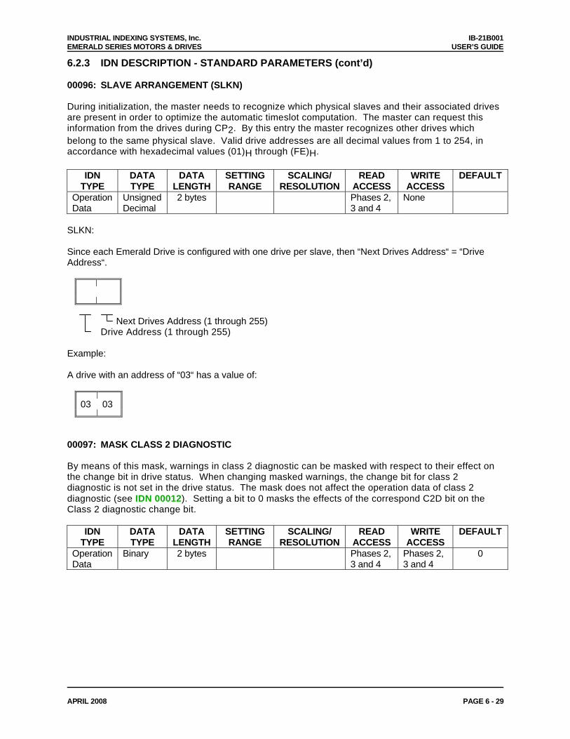
INDUSTRIAL INDEXING SYSTEMS, Inc. IB-21B001 EMERALD SERIES MOTORS & DRIVES USER’S GUIDE
APRIL 2008 PAGE 6 - 29
6.2.3 IDN DESCRIPTION - STANDARD PARAMETERS (cont’d) 00096: SLAVE ARRANGEMENT (SLKN) During initialization, the master needs to recognize which physical slaves and their associated drives are present in order to optimize the automatic timeslot computation. The master can request this information from the drives during CP2. By this entry the master recognizes other drives which belong to the same physical slave. Valid drive addresses are all decimal values from 1 to 254, in accordance with hexadecimal values (01)H through (FE)H.
IDN TYPE
DATA TYPE
DATA LENGTH
SETTING RANGE
SCALING/ RESOLUTION
READ ACCESS
WRITE ACCESS
DEFAULT
Operation Data
Unsigned Decimal
2 bytes Phases 2, 3 and 4
None
SLKN: Since each Emerald Drive is configured with one drive per slave, then “Next Drives Address“ = “Drive Address“.
Next Drives Address (1 through 255) Drive Address (1 through 255) Example: A drive with an address of “03“ has a value of:
03 03
00097: MASK CLASS 2 DIAGNOSTIC By means of this mask, warnings in class 2 diagnostic can be masked with respect to their effect on the change bit in drive status. When changing masked warnings, the change bit for class 2 diagnostic is not set in the drive status. The mask does not affect the operation data of class 2 diagnostic (see IDN 00012). Setting a bit to 0 masks the effects of the correspond C2D bit on the Class 2 diagnostic change bit.
IDN TYPE
DATA TYPE
DATA LENGTH
SETTING RANGE
SCALING/ RESOLUTION
READ ACCESS
WRITE ACCESS
DEFAULT
Operation Data
Binary 2 bytes Phases 2, 3 and 4
Phases 2, 3 and 4
0
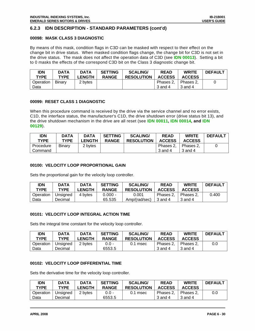
INDUSTRIAL INDEXING SYSTEMS, Inc. IB-21B001 EMERALD SERIES MOTORS & DRIVES USER’S GUIDE
APRIL 2008 PAGE 6 - 30
6.2.3 IDN DESCRIPTION - STANDARD PARAMETERS (cont’d) 00098: MASK CLASS 3 DIAGNOSTIC By means of this mask, condition flags in C3D can be masked with respect to their effect on the change bit in drive status. When masked condition flags change, the change bit for C3D is not set in the drive status. The mask does not affect the operation data of C3D (see IDN 00013). Setting a bit to 0 masks the effects of the correspond C3D bit on the Class 3 diagnostic change bit.
IDN TYPE
DATA TYPE
DATA LENGTH
SETTING RANGE
SCALING/ RESOLUTION
READ ACCESS
WRITE ACCESS
DEFAULT
Operation Data
Binary 2 bytes Phases 2, 3 and 4
Phases 2, 3 and 4
0
00099: RESET CLASS 1 DIAGNOSTIC When this procedure command is received by the drive via the service channel and no error exists, C1D, the interface status, the manufacturer's C1D, the drive shutdown error (drive status bit 13), and the drive shutdown mechanism in the drive are all reset (see IDN 00011, IDN 00014, and IDN 00129).
IDN TYPE
DATA TYPE
DATA LENGTH
SETTING RANGE
SCALING/ RESOLUTION
READ ACCESS
WRITE ACCESS
DEFAULT
Procedure Command
Binary 2 bytes Phases 2, 3 and 4
Phases 2, 3 and 4
0
00100: VELOCITY LOOP PROPORTIONAL GAIN Sets the proportional gain for the velocity loop controller.
IDN TYPE
DATA TYPE
DATA LENGTH
SETTING RANGE
SCALING/ RESOLUTION
READ ACCESS
WRITE ACCESS
DEFAULT
Operation Data
Unsigned Decimal
4 bytes 0.000 - 65.535
0.001 Amp/(rad/sec)
Phases 2, 3 and 4
Phases 2, 3 and 4
0.400
00101: VELOCITY LOOP INTEGRAL ACTION TIME Sets the integral time constant for the velocity loop controller.
IDN TYPE
DATA TYPE
DATA LENGTH
SETTING RANGE
SCALING/ RESOLUTION
READ ACCESS
WRITE ACCESS
DEFAULT
Operation Data
Unsigned Decimal
2 bytes 0.0 - 6553.5
0.1 msec Phases 2, 3 and 4
Phases 2, 3 and 4
0.0
00102: VELOCITY LOOP DIFFERENTIAL TIME Sets the derivative time for the velocity loop controller.
IDN TYPE
DATA TYPE
DATA LENGTH
SETTING RANGE
SCALING/ RESOLUTION
READ ACCESS
WRITE ACCESS
DEFAULT
Operation Data
Unsigned Decimal
2 bytes 0.0 - 6553.5
0.1 msec Phases 2, 3 and 4
Phases 2, 3 and 4
0.0
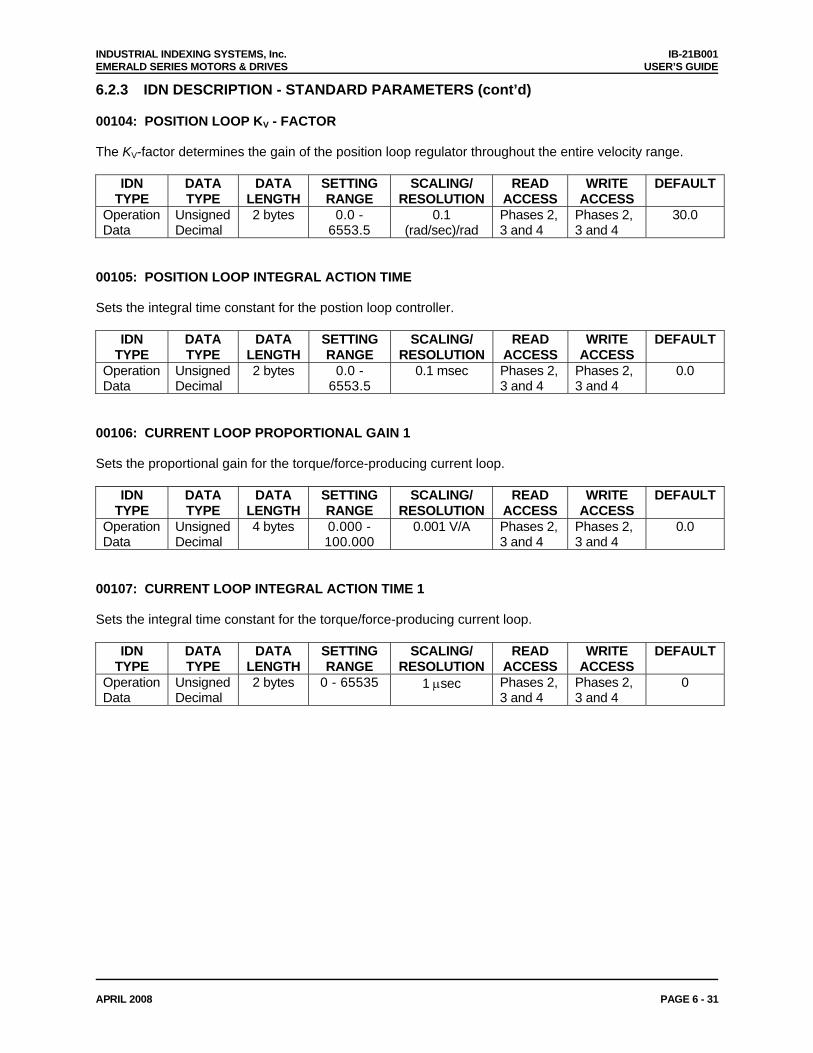
INDUSTRIAL INDEXING SYSTEMS, Inc. IB-21B001 EMERALD SERIES MOTORS & DRIVES USER’S GUIDE
APRIL 2008 PAGE 6 - 31
6.2.3 IDN DESCRIPTION - STANDARD PARAMETERS (cont’d) 00104: POSITION LOOP KV - FACTOR The KV-factor determines the gain of the position loop regulator throughout the entire velocity range.
IDN TYPE
DATA TYPE
DATA LENGTH
SETTING RANGE
SCALING/ RESOLUTION
READ ACCESS
WRITE ACCESS
DEFAULT
Operation Data
Unsigned Decimal
2 bytes 0.0 - 6553.5
0.1 (rad/sec)/rad
Phases 2, 3 and 4
Phases 2, 3 and 4
30.0
00105: POSITION LOOP INTEGRAL ACTION TIME Sets the integral time constant for the postion loop controller.
IDN TYPE
DATA TYPE
DATA LENGTH
SETTING RANGE
SCALING/ RESOLUTION
READ ACCESS
WRITE ACCESS
DEFAULT
Operation Data
Unsigned Decimal
2 bytes 0.0 - 6553.5
0.1 msec Phases 2, 3 and 4
Phases 2, 3 and 4
0.0
00106: CURRENT LOOP PROPORTIONAL GAIN 1 Sets the proportional gain for the torque/force-producing current loop.
IDN TYPE
DATA TYPE
DATA LENGTH
SETTING RANGE
SCALING/ RESOLUTION
READ ACCESS
WRITE ACCESS
DEFAULT
Operation Data
Unsigned Decimal
4 bytes 0.000 - 100.000
0.001 V/A Phases 2, 3 and 4
Phases 2, 3 and 4
0.0
00107: CURRENT LOOP INTEGRAL ACTION TIME 1 Sets the integral time constant for the torque/force-producing current loop.
IDN TYPE
DATA TYPE
DATA LENGTH
SETTING RANGE
SCALING/ RESOLUTION
READ ACCESS
WRITE ACCESS
DEFAULT
Operation Data
Unsigned Decimal
2 bytes 0 - 65535 1 μsec Phases 2, 3 and 4
Phases 2, 3 and 4
0
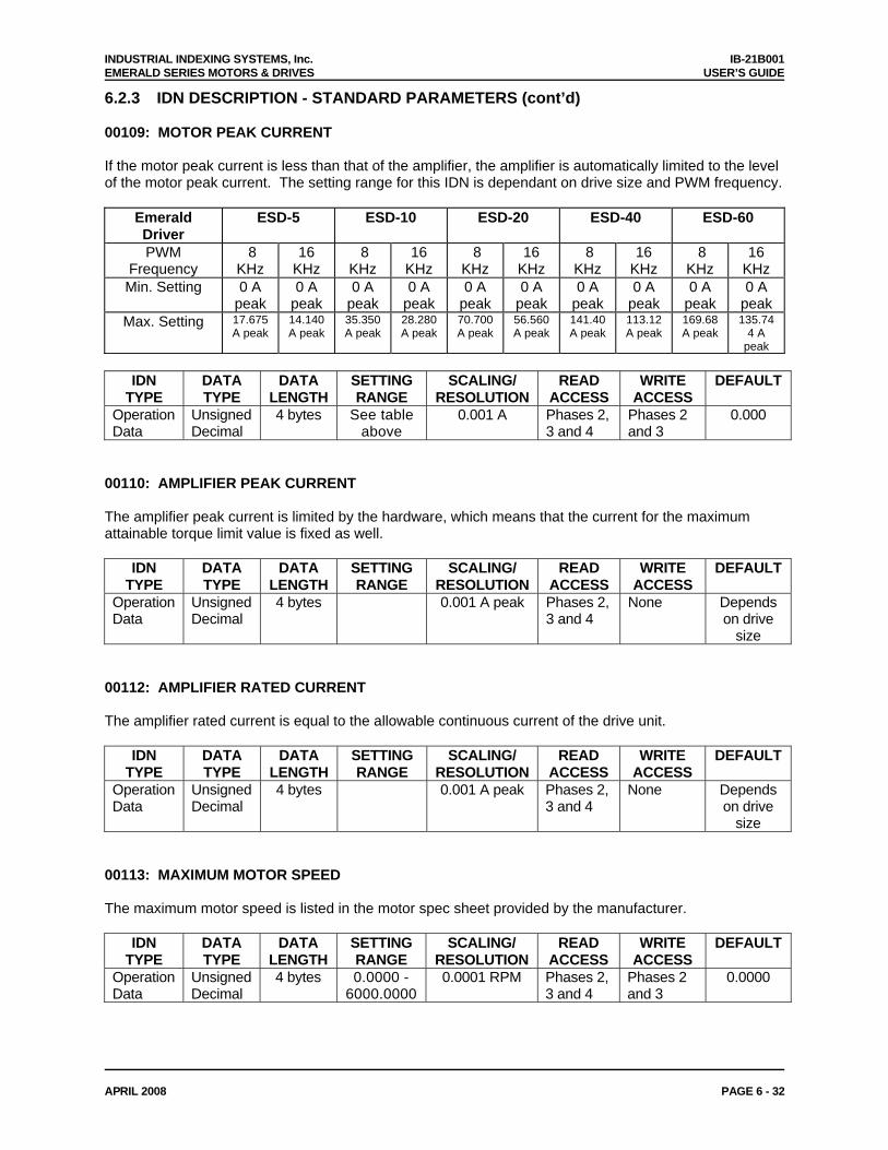
INDUSTRIAL INDEXING SYSTEMS, Inc. IB-21B001 EMERALD SERIES MOTORS & DRIVES USER’S GUIDE
APRIL 2008 PAGE 6 - 32
6.2.3 IDN DESCRIPTION - STANDARD PARAMETERS (cont’d) 00109: MOTOR PEAK CURRENT If the motor peak current is less than that of the amplifier, the amplifier is automatically limited to the level of the motor peak current. The setting range for this IDN is dependant on drive size and PWM frequency.
Emerald Driver
ESD-5 ESD-10 ESD-20 ESD-40 ESD-60
PWM Frequency
8 KHz
16 KHz
8 KHz
16 KHz
8 KHz
16 KHz
8 KHz
16 KHz
8 KHz
16 KHz
Min. Setting 0 A peak
0 A peak
0 A peak
0 A peak
0 A peak
0 A peak
0 A peak
0 A peak
0 A peak
0 A peak
Max. Setting 17.675 A peak
14.140 A peak
35.350 A peak
28.280 A peak
70.700 A peak
56.560 A peak
141.40 A peak
113.12 A peak
169.68 A peak
135.744 A
peak
IDN TYPE
DATA TYPE
DATA LENGTH
SETTING RANGE
SCALING/ RESOLUTION
READ ACCESS
WRITE ACCESS
DEFAULT
Operation Data
Unsigned Decimal
4 bytes See table above
0.001 A Phases 2, 3 and 4
Phases 2 and 3
0.000
00110: AMPLIFIER PEAK CURRENT The amplifier peak current is limited by the hardware, which means that the current for the maximum attainable torque limit value is fixed as well.
IDN TYPE
DATA TYPE
DATA LENGTH
SETTING RANGE
SCALING/ RESOLUTION
READ ACCESS
WRITE ACCESS
DEFAULT
Operation Data
Unsigned Decimal
4 bytes 0.001 A peak Phases 2, 3 and 4
None Depends on drive
size 00112: AMPLIFIER RATED CURRENT The amplifier rated current is equal to the allowable continuous current of the drive unit.
IDN TYPE
DATA TYPE
DATA LENGTH
SETTING RANGE
SCALING/ RESOLUTION
READ ACCESS
WRITE ACCESS
DEFAULT
Operation Data
Unsigned Decimal
4 bytes 0.001 A peak Phases 2, 3 and 4
None Depends on drive
size 00113: MAXIMUM MOTOR SPEED The maximum motor speed is listed in the motor spec sheet provided by the manufacturer.
IDN TYPE
DATA TYPE
DATA LENGTH
SETTING RANGE
SCALING/ RESOLUTION
READ ACCESS
WRITE ACCESS
DEFAULT
Operation Data
Unsigned Decimal
4 bytes 0.0000 - 6000.0000
0.0001 RPM Phases 2, 3 and 4
Phases 2 and 3
0.0000
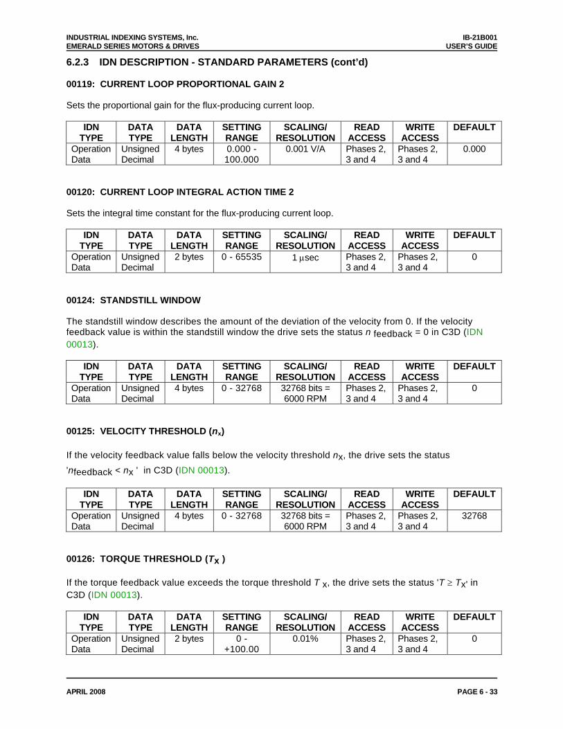
INDUSTRIAL INDEXING SYSTEMS, Inc. IB-21B001 EMERALD SERIES MOTORS & DRIVES USER’S GUIDE
APRIL 2008 PAGE 6 - 33
6.2.3 IDN DESCRIPTION - STANDARD PARAMETERS (cont’d) 00119: CURRENT LOOP PROPORTIONAL GAIN 2 Sets the proportional gain for the flux-producing current loop.
IDN TYPE
DATA TYPE
DATA LENGTH
SETTING RANGE
SCALING/ RESOLUTION
READ ACCESS
WRITE ACCESS
DEFAULT
Operation Data
Unsigned Decimal
4 bytes 0.000 - 100.000
0.001 V/A Phases 2, 3 and 4
Phases 2, 3 and 4
0.000
00120: CURRENT LOOP INTEGRAL ACTION TIME 2 Sets the integral time constant for the flux-producing current loop.
IDN TYPE
DATA TYPE
DATA LENGTH
SETTING RANGE
SCALING/ RESOLUTION
READ ACCESS
WRITE ACCESS
DEFAULT
Operation Data
Unsigned Decimal
2 bytes 0 - 65535 1 μsec Phases 2, 3 and 4
Phases 2, 3 and 4
0
00124: STANDSTILL WINDOW The standstill window describes the amount of the deviation of the velocity from 0. If the velocity feedback value is within the standstill window the drive sets the status n feedback = 0 in C3D (IDN 00013).
IDN TYPE
DATA TYPE
DATA LENGTH
SETTING RANGE
SCALING/ RESOLUTION
READ ACCESS
WRITE ACCESS
DEFAULT
Operation Data
Unsigned Decimal
4 bytes 0 - 32768 32768 bits = 6000 RPM
Phases 2, 3 and 4
Phases 2, 3 and 4
0
00125: VELOCITY THRESHOLD (nx) If the velocity feedback value falls below the velocity threshold nx, the drive sets the status 'nfeedback < nx ' in C3D (IDN 00013).
IDN TYPE
DATA TYPE
DATA LENGTH
SETTING RANGE
SCALING/ RESOLUTION
READ ACCESS
WRITE ACCESS
DEFAULT
Operation Data
Unsigned Decimal
4 bytes 0 - 32768 32768 bits = 6000 RPM
Phases 2, 3 and 4
Phases 2, 3 and 4
32768
00126: TORQUE THRESHOLD (Tx ) If the torque feedback value exceeds the torque threshold T x, the drive sets the status 'T ≥ Tx' in C3D (IDN 00013).
IDN TYPE
DATA TYPE
DATA LENGTH
SETTING RANGE
SCALING/ RESOLUTION
READ ACCESS
WRITE ACCESS
DEFAULT
Operation Data
Unsigned Decimal
2 bytes 0 - +100.00
0.01% Phases 2, 3 and 4
Phases 2, 3 and 4
0
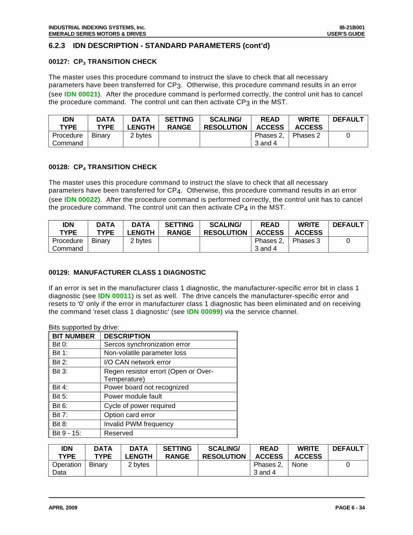
INDUSTRIAL INDEXING SYSTEMS, Inc. IB-21B001 EMERALD SERIES MOTORS & DRIVES USER’S GUIDE
APRIL 2009 PAGE 6 - 34
6.2.3 IDN DESCRIPTION - STANDARD PARAMETERS (cont’d) 00127: CP3 TRANSITION CHECK The master uses this procedure command to instruct the slave to check that all necessary parameters have been transferred for CP3. Otherwise, this procedure command results in an error (see IDN 00021). After the procedure command is performed correctly, the control unit has to cancel the procedure command. The control unit can then activate CP3 in the MST.
IDN TYPE
DATA TYPE
DATA LENGTH
SETTING RANGE
SCALING/ RESOLUTION
READ ACCESS
WRITE ACCESS
DEFAULT
Procedure Command
Binary 2 bytes Phases 2, 3 and 4
Phases 2 0
00128: CP4 TRANSITION CHECK The master uses this procedure command to instruct the slave to check that all necessary parameters have been transferred for CP4. Otherwise, this procedure command results in an error (see IDN 00022). After the procedure command is performed correctly, the control unit has to cancel the procedure command. The control unit can then activate CP4 in the MST.
IDN TYPE
DATA TYPE
DATA LENGTH
SETTING RANGE
SCALING/ RESOLUTION
READ ACCESS
WRITE ACCESS
DEFAULT
Procedure Command
Binary 2 bytes Phases 2, 3 and 4
Phases 3 0
00129: MANUFACTURER CLASS 1 DIAGNOSTIC If an error is set in the manufacturer class 1 diagnostic, the manufacturer-specific error bit in class 1 diagnostic (see IDN 00011) is set as well. The drive cancels the manufacturer-specific error and resets to '0' only if the error in manufacturer class 1 diagnostic has been eliminated and on receiving the command 'reset class 1 diagnostic' (see IDN 00099) via the service channel. Bits supported by drive: BIT NUMBER DESCRIPTION Bit 0: Sercos synchronization error Bit 1: Non-volatile parameter loss Bit 2: I/O CAN network error Bit 3: Regen resistor errort (Open or Over-
Temperature) Bit 4: Power board not recognized Bit 5: Power module fault Bit 6: Cycle of power required Bit 7: Option card error Bit 8: Invalid PWM frequency Bit 9 - 15: Reserved
IDN
TYPE DATA TYPE
DATA LENGTH
SETTING RANGE
SCALING/ RESOLUTION
READ ACCESS
WRITE ACCESS
DEFAULT
Operation Data
Binary 2 bytes Phases 2, 3 and 4
None 0

INDUSTRIAL INDEXING SYSTEMS, Inc. IB-21B001 EMERALD SERIES MOTORS & DRIVES USER’S GUIDE
APRIL 2008 PAGE 6 - 35
6.2.3 IDN DESCRIPTION - STANDARD PARAMETERS (cont’d) 00130: PROBE VALUE 1 POSITIVE EDGE Based on the configure Probe Feedback Source (IDN 33200) the drive stores position feedback value in the measuring cycle in this parameter following the positive edge of the input signal of probe 1 (see IDN 00401). This allows the control unit to read 'probe value 1 positive edge' at a later time.
IDN TYPE
DATA TYPE
DATA LENGTH
SETTING RANGE
SCALING/ RESOLUTION
READ ACCESS
WRITE ACCESS
DEFAULT
Operation Data
Signed Decimal
4 bytes Phases 2, 3 and 4
None
00131: PROBE VALUE 1 NEGATIVE EDGE Based on the configure Probe Feedback Source (IDN 33200) the drive stores position feedback value in the measuring cycle in this parameter following the negative edge of the input signal of probe 1 (see IDN 00401). This allows the control unit to read 'probe value 1 negative edge' at a later time.
IDN TYPE
DATA TYPE
DATA LENGTH
SETTING RANGE
SCALING/ RESOLUTION
READ ACCESS
WRITE ACCESS
DEFAULT
Operation Data
Signed Decimal
4 bytes Phases 2, 3 and 4
None
00132: PROBE VALUE 2 POSITIVE EDGE Based on the configured Probe Feedback Source (IDN 33200) the drive stores position feedback value in the measuring cycle in this parameter following the positive edge of the input signal of probe 2 (see IDN 00402). This allows the control unit to read 'probe value 2 positive edge' at a later time.
IDN TYPE
DATA TYPE
DATA LENGTH
SETTING RANGE
SCALING/ RESOLUTION
READ ACCESS
WRITE ACCESS
DEFAULT
Operation Data
Signed Decimal
4 bytes Phases 2, 3 and 4
None
00133: PROBE VALUE 2 NEGATIVE EDGE Based on the configured Probe Feedback Source (IDN 33200) the drive stores position feedback value in the measuring cycle in this parameter following the negative edge of the input signal of probe 2 (see IDN 00402). This allows the control unit to read 'probe value 2 negative edge' at a later time.
IDN TYPE
DATA TYPE
DATA LENGTH
SETTING RANGE
SCALING/ RESOLUTION
READ ACCESS
WRITE ACCESS
DEFAULT
Operation Data
Signed Decimal
4 bytes Phases 2, 3 and 4
None
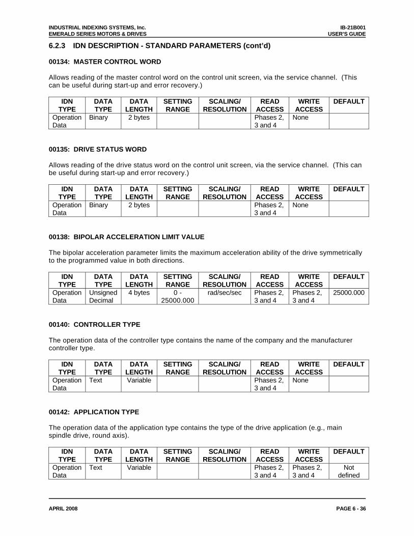
INDUSTRIAL INDEXING SYSTEMS, Inc. IB-21B001 EMERALD SERIES MOTORS & DRIVES USER’S GUIDE
APRIL 2008 PAGE 6 - 36
6.2.3 IDN DESCRIPTION - STANDARD PARAMETERS (cont’d) 00134: MASTER CONTROL WORD Allows reading of the master control word on the control unit screen, via the service channel. (This can be useful during start-up and error recovery.)
IDN TYPE
DATA TYPE
DATA LENGTH
SETTING RANGE
SCALING/ RESOLUTION
READ ACCESS
WRITE ACCESS
DEFAULT
Operation Data
Binary 2 bytes Phases 2, 3 and 4
None
00135: DRIVE STATUS WORD Allows reading of the drive status word on the control unit screen, via the service channel. (This can be useful during start-up and error recovery.)
IDN TYPE
DATA TYPE
DATA LENGTH
SETTING RANGE
SCALING/ RESOLUTION
READ ACCESS
WRITE ACCESS
DEFAULT
Operation Data
Binary 2 bytes Phases 2, 3 and 4
None
00138: BIPOLAR ACCELERATION LIMIT VALUE The bipolar acceleration parameter limits the maximum acceleration ability of the drive symmetrically to the programmed value in both directions.
IDN TYPE
DATA TYPE
DATA LENGTH
SETTING RANGE
SCALING/ RESOLUTION
READ ACCESS
WRITE ACCESS
DEFAULT
Operation Data
Unsigned Decimal
4 bytes 0 -25000.000
rad/sec/sec Phases 2, 3 and 4
Phases 2, 3 and 4
25000.000
00140: CONTROLLER TYPE The operation data of the controller type contains the name of the company and the manufacturer controller type.
IDN TYPE
DATA TYPE
DATA LENGTH
SETTING RANGE
SCALING/ RESOLUTION
READ ACCESS
WRITE ACCESS
DEFAULT
Operation Data
Text Variable Phases 2, 3 and 4
None
00142: APPLICATION TYPE The operation data of the application type contains the type of the drive application (e.g., main spindle drive, round axis).
IDN TYPE
DATA TYPE
DATA LENGTH
SETTING RANGE
SCALING/ RESOLUTION
READ ACCESS
WRITE ACCESS
DEFAULT
Operation Data
Text Variable Phases 2, 3 and 4
Phases 2, 3 and 4
Not defined
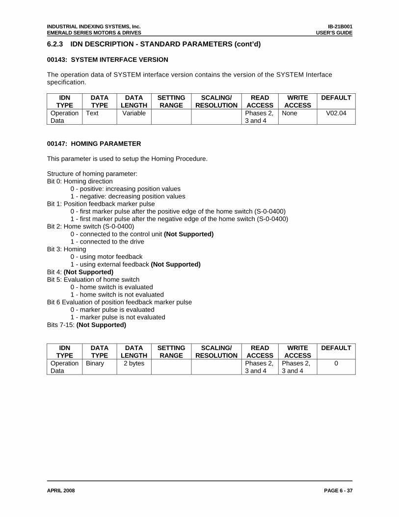
INDUSTRIAL INDEXING SYSTEMS, Inc. IB-21B001 EMERALD SERIES MOTORS & DRIVES USER’S GUIDE
APRIL 2008 PAGE 6 - 37
6.2.3 IDN DESCRIPTION - STANDARD PARAMETERS (cont’d) 00143: SYSTEM INTERFACE VERSION The operation data of SYSTEM interface version contains the version of the SYSTEM Interface specification.
IDN TYPE
DATA TYPE
DATA LENGTH
SETTING RANGE
SCALING/ RESOLUTION
READ ACCESS
WRITE ACCESS
DEFAULT
Operation Data
Text Variable Phases 2, 3 and 4
None V02.04
00147: HOMING PARAMETER This parameter is used to setup the Homing Procedure. Structure of homing parameter: Bit 0: Homing direction
0 - positive: increasing position values 1 - negative: decreasing position values
Bit 1: Position feedback marker pulse 0 - first marker pulse after the positive edge of the home switch (S-0-0400) 1 - first marker pulse after the negative edge of the home switch (S-0-0400)
Bit 2: Home switch (S-0-0400) 0 - connected to the control unit (Not Supported) 1 - connected to the drive
Bit 3: Homing 0 - using motor feedback 1 - using external feedback (Not Supported)
Bit 4: (Not Supported) Bit 5: Evaluation of home switch
0 - home switch is evaluated 1 - home switch is not evaluated
Bit 6 Evaluation of position feedback marker pulse 0 - marker pulse is evaluated 1 - marker pulse is not evaluated
Bits 7-15: (Not Supported)
IDN TYPE
DATA TYPE
DATA LENGTH
SETTING RANGE
SCALING/ RESOLUTION
READ ACCESS
WRITE ACCESS
DEFAULT
Operation Data
Binary 2 bytes Phases 2, 3 and 4
Phases 2, 3 and 4
0
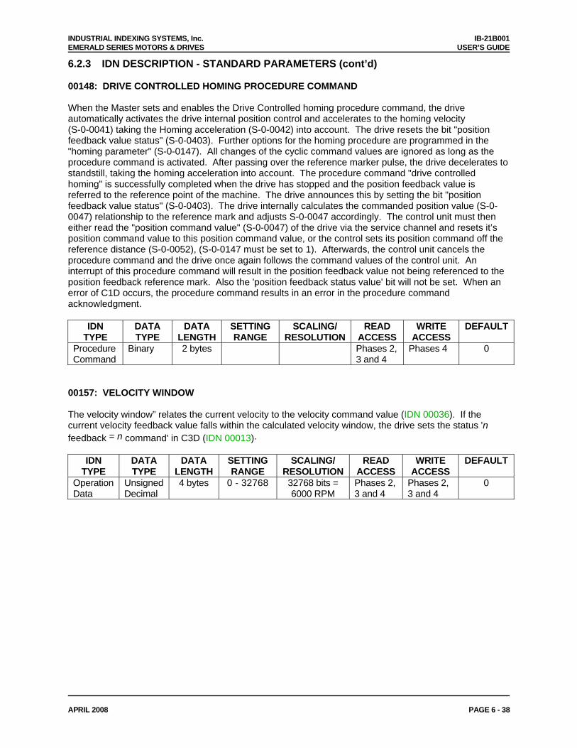
INDUSTRIAL INDEXING SYSTEMS, Inc. IB-21B001 EMERALD SERIES MOTORS & DRIVES USER’S GUIDE
APRIL 2008 PAGE 6 - 38
6.2.3 IDN DESCRIPTION - STANDARD PARAMETERS (cont’d) 00148: DRIVE CONTROLLED HOMING PROCEDURE COMMAND When the Master sets and enables the Drive Controlled homing procedure command, the drive automatically activates the drive internal position control and accelerates to the homing velocity (S-0-0041) taking the Homing acceleration (S-0-0042) into account. The drive resets the bit "position feedback value status" (S-0-0403). Further options for the homing procedure are programmed in the "homing parameter" (S-0-0147). All changes of the cyclic command values are ignored as long as the procedure command is activated. After passing over the reference marker pulse, the drive decelerates to standstill, taking the homing acceleration into account. The procedure command "drive controlled homing" is successfully completed when the drive has stopped and the position feedback value is referred to the reference point of the machine. The drive announces this by setting the bit "position feedback value status" (S-0-0403). The drive internally calculates the commanded position value (S-0-0047) relationship to the reference mark and adjusts S-0-0047 accordingly. The control unit must then either read the "position command value" (S-0-0047) of the drive via the service channel and resets it’s position command value to this position command value, or the control sets its position command off the reference distance (S-0-0052), (S-0-0147 must be set to 1). Afterwards, the control unit cancels the procedure command and the drive once again follows the command values of the control unit. An interrupt of this procedure command will result in the position feedback value not being referenced to the position feedback reference mark. Also the 'position feedback status value' bit will not be set. When an error of C1D occurs, the procedure command results in an error in the procedure command acknowledgment.
IDN TYPE
DATA TYPE
DATA LENGTH
SETTING RANGE
SCALING/ RESOLUTION
READ ACCESS
WRITE ACCESS
DEFAULT
Procedure Command
Binary 2 bytes Phases 2, 3 and 4
Phases 4 0
00157: VELOCITY WINDOW The velocity window” relates the current velocity to the velocity command value (IDN 00036). If the current velocity feedback value falls within the calculated velocity window, the drive sets the status 'n feedback = n command' in C3D (IDN 00013).
IDN TYPE
DATA TYPE
DATA LENGTH
SETTING RANGE
SCALING/ RESOLUTION
READ ACCESS
WRITE ACCESS
DEFAULT
Operation Data
Unsigned Decimal
4 bytes 0 - 32768 32768 bits = 6000 RPM
Phases 2, 3 and 4
Phases 2, 3 and 4
0
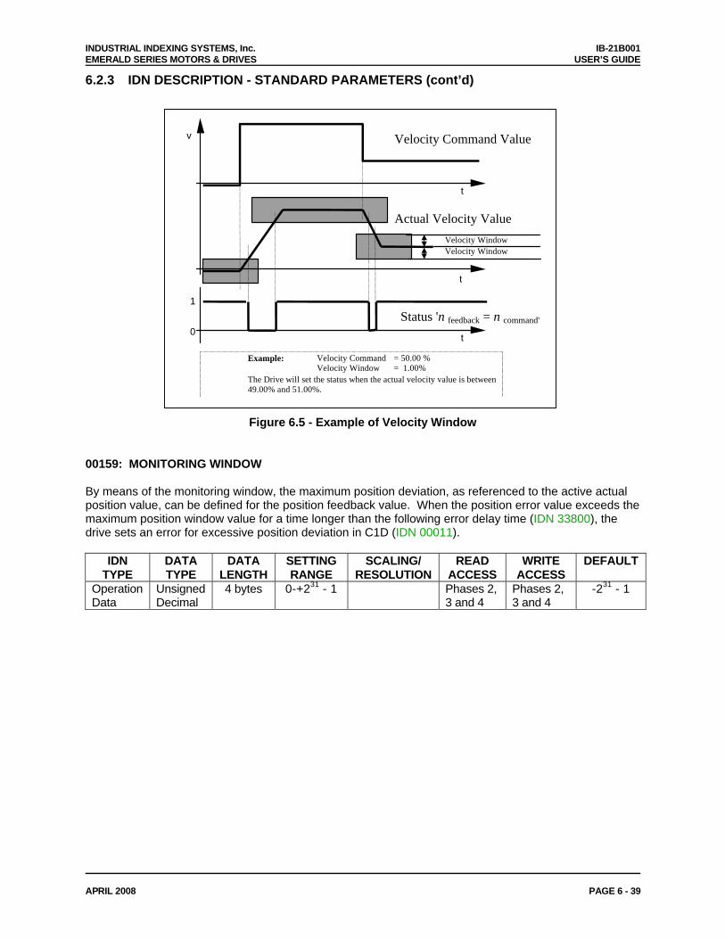
INDUSTRIAL INDEXING SYSTEMS, Inc. IB-21B001 EMERALD SERIES MOTORS & DRIVES USER’S GUIDE
APRIL 2008 PAGE 6 - 39
6.2.3 IDN DESCRIPTION - STANDARD PARAMETERS (cont’d)
v
t
t
t
Velocity Command Value
Actual Velocity Value
Status 'n feedback = n command'0
1
Velocity WindowVelocity Window
Example: Velocity Command = 50.00 %Velocity Window = 1.00%
The Drive will set the status when the actual velocity value is between49.00% and 51.00%.
Figure 6.5 - Example of Velocity Window
00159: MONITORING WINDOW By means of the monitoring window, the maximum position deviation, as referenced to the active actual position value, can be defined for the position feedback value. When the position error value exceeds the maximum position window value for a time longer than the following error delay time (IDN 33800), the drive sets an error for excessive position deviation in C1D (IDN 00011).
IDN TYPE
DATA TYPE
DATA LENGTH
SETTING RANGE
SCALING/ RESOLUTION
READ ACCESS
WRITE ACCESS
DEFAULT
Operation Data
Unsigned Decimal
4 bytes 0-+231 - 1 Phases 2, 3 and 4
Phases 2, 3 and 4
-231 - 1
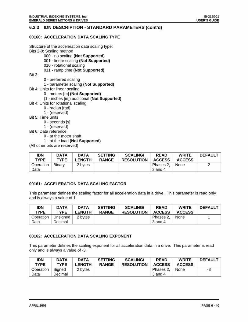
INDUSTRIAL INDEXING SYSTEMS, Inc. IB-21B001 EMERALD SERIES MOTORS & DRIVES USER’S GUIDE
APRIL 2008 PAGE 6 - 40
6.2.3 IDN DESCRIPTION - STANDARD PARAMETERS (cont’d) 00160: ACCELERATION DATA SCALING TYPE Structure of the acceleration data scaling type: Bits 2-0: Scaling method
000 - no scaling (Not Supported) 001 - linear scaling (Not Supported) 010 - rotational scaling 011 - ramp time (Not Supported)
Bit 3: 0 - preferred scaling 1 - parameter scaling (Not Supported)
Bit 4: Units for linear scaling 0 - meters [m] (Not Supported) (1 - inches [in]) additional (Not Supported)
Bit 4: Units for rotational scaling 0 - radian [rad] 1 - (reserved)
Bit 5: Time units 0 - seconds [s] 1 - (reserved)
Bit 6: Data reference 0 - at the motor shaft 1 - at the load (Not Supported)
(All other bits are reserved)
IDN TYPE
DATA TYPE
DATA LENGTH
SETTING RANGE
SCALING/ RESOLUTION
READ ACCESS
WRITE ACCESS
DEFAULT
Operation Data
Binary 2 bytes Phases 2, 3 and 4
None 2
00161: ACCELERATION DATA SCALING FACTOR This parameter defines the scaling factor for all acceleration data in a drive. This parameter is read only and is always a value of 1.
IDN TYPE
DATA TYPE
DATA LENGTH
SETTING RANGE
SCALING/ RESOLUTION
READ ACCESS
WRITE ACCESS
DEFAULT
Operation Data
Unsigned Decimal
2 bytes Phases 2, 3 and 4
None 1
00162: ACCELERATION DATA SCALING EXPONENT This parameter defines the scaling exponent for all acceleration data in a drive. This parameter is read only and is always a value of -3.
IDN TYPE
DATA TYPE
DATA LENGTH
SETTING RANGE
SCALING/ RESOLUTION
READ ACCESS
WRITE ACCESS
DEFAULT
Operation Data
Signed Decimal
2 bytes Phases 2, 3 and 4
None -3
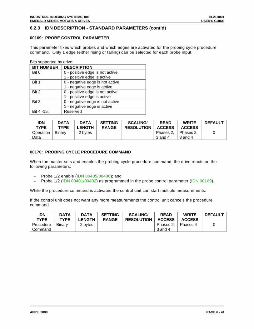
INDUSTRIAL INDEXING SYSTEMS, Inc. IB-21B001 EMERALD SERIES MOTORS & DRIVES USER’S GUIDE
APRIL 2008 PAGE 6 - 41
6.2.3 IDN DESCRIPTION - STANDARD PARAMETERS (cont’d) 00169: PROBE CONTROL PARAMETER This parameter fixes which probes and which edges are activated for the probing cycle procedure command. Only 1 edge (either rising or falling) can be selected for each probe input. Bits supported by drive: BIT NUMBER DESCRIPTION Bit 0: 0 - positive edge is not active
1 - positive edge is active Bit 1: 0 - negative edge is not active
1 - negative edge is active Bit 2: 0 - positive edge is not active
1 - positive edge is active Bit 3: 0 - negative edge is not active
1 - negative edge is active Bit 4 -15: Reserved
IDN
TYPE DATA TYPE
DATA LENGTH
SETTING RANGE
SCALING/ RESOLUTION
READ ACCESS
WRITE ACCESS
DEFAULT
Operation Data
Binary 2 bytes Phases 2, 3 and 4
Phases 2, 3 and 4
0
00170: PROBING CYCLE PROCEDURE COMMAND When the master sets and enables the probing cycle procedure command, the drive reacts on the following parameters:
– Probe 1/2 enable (IDN 00405/00406); and – Probe 1/2 (IDN 00401/00402) as programmed in the probe control parameter (IDN 00169).
While the procedure command is activated the control unit can start multiple measurements. If the control unit does not want any more measurements the control unit cancels the procedure command.
IDN TYPE
DATA TYPE
DATA LENGTH
SETTING RANGE
SCALING/ RESOLUTION
READ ACCESS
WRITE ACCESS
DEFAULT
Procedure Command
Binary 2 bytes Phases 2, 3 and 4
Phases 4 0
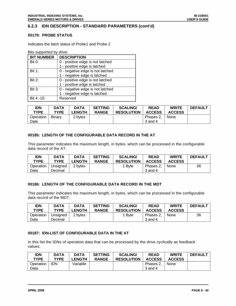
INDUSTRIAL INDEXING SYSTEMS, Inc. IB-21B001 EMERALD SERIES MOTORS & DRIVES USER’S GUIDE
APRIL 2008 PAGE 6 - 42
6.2.3 IDN DESCRIPTION - STANDARD PARAMETERS (cont’d) 00179: PROBE STATUS Indicates the latch status of Probe1 and Probe 2 Bits supported by drive: BIT NUMBER DESCRIPTION Bit 0: 0 - positive edge is not latched
1 - positive edge is latched Bit 1: 0 - negative edge is not latched
1 - negative edge is latched Bit 2: 0 - positive edge is not latched
1 - positive edge is latched Bit 3: 0 - negative edge is not latched
1 - negative edge is latched Bit 4 -15: Reserved
IDN
TYPE DATA TYPE
DATA LENGTH
SETTING RANGE
SCALING/ RESOLUTION
READ ACCESS
WRITE ACCESS
DEFAULT
Operation Data
Binary 2 bytes Phases 2, 3 and 4
None
00185: LENGTH OF THE CONFIGURABLE DATA RECORD IN THE AT This parameter indicates the maximum length, in bytes, which can be processed in the configurable data record of the AT.
IDN TYPE
DATA TYPE
DATA LENGTH
SETTING RANGE
SCALING/ RESOLUTION
READ ACCESS
WRITE ACCESS
DEFAULT
Operation Data
Unsigned Decimal
2 bytes 1 Byte Phases 2, 3 and 4
None 36
00186: LENGTH OF THE CONFIGURABLE DATA RECORD IN THE MDT This parameter indicates the maximum length, in bytes, which can be processed in the configurable data record of the MDT.
IDN TYPE
DATA TYPE
DATA LENGTH
SETTING RANGE
SCALING/ RESOLUTION
READ ACCESS
WRITE ACCESS
DEFAULT
Operation Data
Unsigned Decimal
2 bytes 1 Byte Phases 2, 3 and 4
None 36
00187: IDN-LIST OF CONFIGURABLE DATA IN THE AT In this list the IDNs of operation data that can be processed by the drive cyclically as feedback values.
IDN TYPE
DATA TYPE
DATA LENGTH
SETTING RANGE
SCALING/ RESOLUTION
READ ACCESS
WRITE ACCESS
DEFAULT
Operation Data
IDN Variable Phases 2, 3 and 4
None
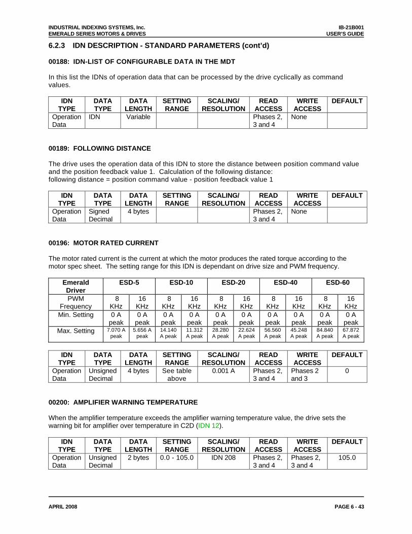
INDUSTRIAL INDEXING SYSTEMS, Inc. IB-21B001 EMERALD SERIES MOTORS & DRIVES USER’S GUIDE
APRIL 2008 PAGE 6 - 43
6.2.3 IDN DESCRIPTION - STANDARD PARAMETERS (cont’d) 00188: IDN-LIST OF CONFIGURABLE DATA IN THE MDT In this list the IDNs of operation data that can be processed by the drive cyclically as command values.
IDN TYPE
DATA TYPE
DATA LENGTH
SETTING RANGE
SCALING/ RESOLUTION
READ ACCESS
WRITE ACCESS
DEFAULT
Operation Data
IDN Variable Phases 2, 3 and 4
None
00189: FOLLOWING DISTANCE The drive uses the operation data of this IDN to store the distance between position command value and the position feedback value 1. Calculation of the following distance: following distance = position command value - position feedback value 1
IDN TYPE
DATA TYPE
DATA LENGTH
SETTING RANGE
SCALING/ RESOLUTION
READ ACCESS
WRITE ACCESS
DEFAULT
Operation Data
Signed Decimal
4 bytes Phases 2, 3 and 4
None
00196: MOTOR RATED CURRENT The motor rated current is the current at which the motor produces the rated torque according to the motor spec sheet. The setting range for this IDN is dependant on drive size and PWM frequency.
Emerald Driver
ESD-5 ESD-10 ESD-20 ESD-40 ESD-60
PWM Frequency
8 KHz
16 KHz
8 KHz
16 KHz
8 KHz
16 KHz
8 KHz
16 KHz
8 KHz
16 KHz
Min. Setting 0 A peak
0 A peak
0 A peak
0 A peak
0 A peak
0 A peak
0 A peak
0 A peak
0 A peak
0 A peak
Max. Setting 7.070 A peak
5.656 A peak
14.140 A peak
11.312 A peak
28.280 A peak
22.624 A peak
56.560 A peak
45.248 A peak
84.840 A peak
67.872 A peak
IDN
TYPE DATA TYPE
DATA LENGTH
SETTING RANGE
SCALING/ RESOLUTION
READ ACCESS
WRITE ACCESS
DEFAULT
Operation Data
Unsigned Decimal
4 bytes See table above
0.001 A Phases 2, 3 and 4
Phases 2 and 3
0
00200: AMPLIFIER WARNING TEMPERATURE When the amplifier temperature exceeds the amplifier warning temperature value, the drive sets the warning bit for amplifier over temperature in C2D (IDN 12).
IDN TYPE
DATA TYPE
DATA LENGTH
SETTING RANGE
SCALING/ RESOLUTION
READ ACCESS
WRITE ACCESS
DEFAULT
Operation Data
Unsigned Decimal
2 bytes 0.0 - 105.0 IDN 208 Phases 2, 3 and 4
Phases 2, 3 and 4
105.0
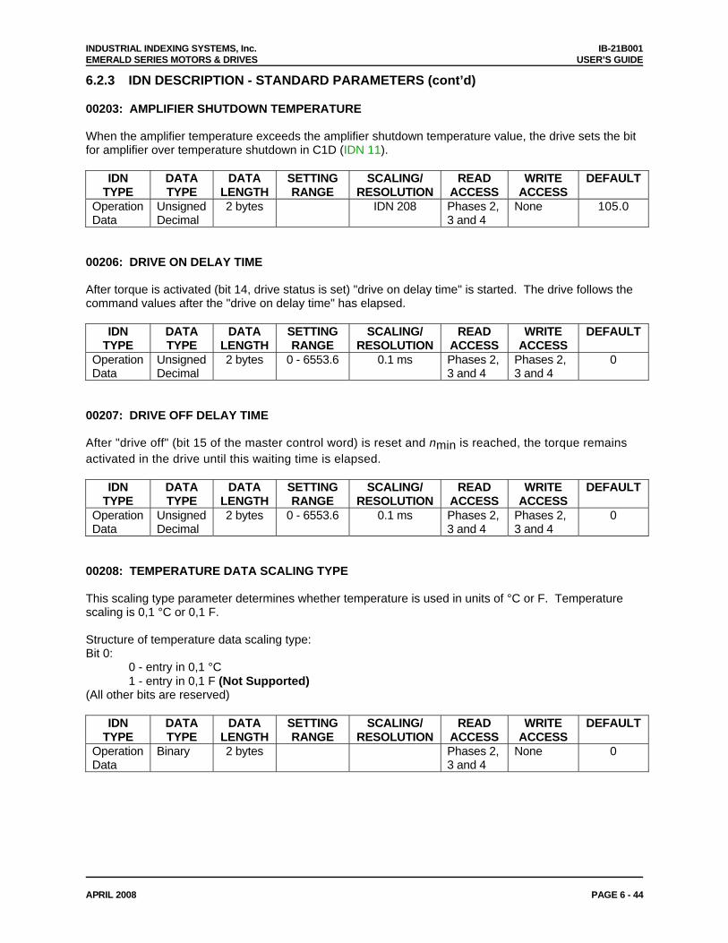
INDUSTRIAL INDEXING SYSTEMS, Inc. IB-21B001 EMERALD SERIES MOTORS & DRIVES USER’S GUIDE
APRIL 2008 PAGE 6 - 44
6.2.3 IDN DESCRIPTION - STANDARD PARAMETERS (cont’d) 00203: AMPLIFIER SHUTDOWN TEMPERATURE When the amplifier temperature exceeds the amplifier shutdown temperature value, the drive sets the bit for amplifier over temperature shutdown in C1D (IDN 11).
IDN TYPE
DATA TYPE
DATA LENGTH
SETTING RANGE
SCALING/ RESOLUTION
READ ACCESS
WRITE ACCESS
DEFAULT
Operation Data
Unsigned Decimal
2 bytes IDN 208 Phases 2, 3 and 4
None 105.0
00206: DRIVE ON DELAY TIME After torque is activated (bit 14, drive status is set) "drive on delay time" is started. The drive follows the command values after the "drive on delay time" has elapsed.
IDN TYPE
DATA TYPE
DATA LENGTH
SETTING RANGE
SCALING/ RESOLUTION
READ ACCESS
WRITE ACCESS
DEFAULT
Operation Data
Unsigned Decimal
2 bytes 0 - 6553.6 0.1 ms Phases 2, 3 and 4
Phases 2, 3 and 4
0
00207: DRIVE OFF DELAY TIME After "drive off" (bit 15 of the master control word) is reset and nmin is reached, the torque remains activated in the drive until this waiting time is elapsed.
IDN TYPE
DATA TYPE
DATA LENGTH
SETTING RANGE
SCALING/ RESOLUTION
READ ACCESS
WRITE ACCESS
DEFAULT
Operation Data
Unsigned Decimal
2 bytes 0 - 6553.6 0.1 ms Phases 2, 3 and 4
Phases 2, 3 and 4
0
00208: TEMPERATURE DATA SCALING TYPE This scaling type parameter determines whether temperature is used in units of °C or F. Temperature scaling is 0,1 °C or 0,1 F. Structure of temperature data scaling type: Bit 0:
0 - entry in 0,1 °C 1 - entry in 0,1 F (Not Supported)
(All other bits are reserved)
IDN TYPE
DATA TYPE
DATA LENGTH
SETTING RANGE
SCALING/ RESOLUTION
READ ACCESS
WRITE ACCESS
DEFAULT
Operation Data
Binary 2 bytes Phases 2, 3 and 4
None 0
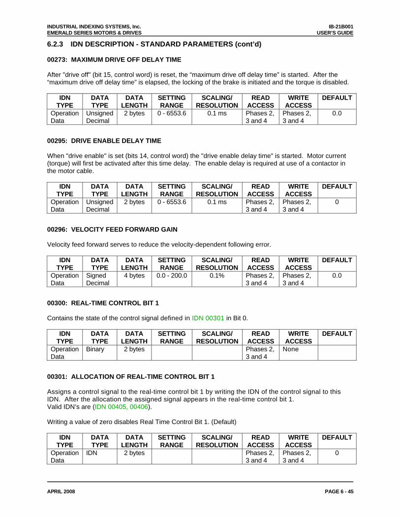
INDUSTRIAL INDEXING SYSTEMS, Inc. IB-21B001 EMERALD SERIES MOTORS & DRIVES USER’S GUIDE
APRIL 2008 PAGE 6 - 45
6.2.3 IDN DESCRIPTION - STANDARD PARAMETERS (cont’d) 00273: MAXIMUM DRIVE OFF DELAY TIME After "drive off" (bit 15, control word) is reset, the “maximum drive off delay time” is started. After the “maximum drive off delay time” is elapsed, the locking of the brake is initiated and the torque is disabled.
IDN TYPE
DATA TYPE
DATA LENGTH
SETTING RANGE
SCALING/ RESOLUTION
READ ACCESS
WRITE ACCESS
DEFAULT
Operation Data
Unsigned Decimal
2 bytes 0 - 6553.6 0.1 ms Phases 2, 3 and 4
Phases 2, 3 and 4
0.0
00295: DRIVE ENABLE DELAY TIME When "drive enable" is set (bits 14, control word) the "drive enable delay time" is started. Motor current (torque) will first be activated after this time delay. The enable delay is required at use of a contactor in the motor cable.
IDN TYPE
DATA TYPE
DATA LENGTH
SETTING RANGE
SCALING/ RESOLUTION
READ ACCESS
WRITE ACCESS
DEFAULT
Operation Data
Unsigned Decimal
2 bytes 0 - 6553.6 0.1 ms Phases 2, 3 and 4
Phases 2, 3 and 4
0
00296: VELOCITY FEED FORWARD GAIN Velocity feed forward serves to reduce the velocity-dependent following error.
IDN TYPE
DATA TYPE
DATA LENGTH
SETTING RANGE
SCALING/ RESOLUTION
READ ACCESS
WRITE ACCESS
DEFAULT
Operation Data
Signed Decimal
4 bytes 0.0 - 200.0 0.1% Phases 2, 3 and 4
Phases 2, 3 and 4
0.0
00300: REAL-TIME CONTROL BIT 1 Contains the state of the control signal defined in IDN 00301 in Bit 0.
IDN TYPE
DATA TYPE
DATA LENGTH
SETTING RANGE
SCALING/ RESOLUTION
READ ACCESS
WRITE ACCESS
DEFAULT
Operation Data
Binary 2 bytes Phases 2, 3 and 4
None
00301: ALLOCATION OF REAL-TIME CONTROL BIT 1 Assigns a control signal to the real-time control bit 1 by writing the IDN of the control signal to this IDN. After the allocation the assigned signal appears in the real-time control bit 1. Valid IDN’s are (IDN 00405, 00406). Writing a value of zero disables Real Time Control Bit 1. (Default)
IDN TYPE
DATA TYPE
DATA LENGTH
SETTING RANGE
SCALING/ RESOLUTION
READ ACCESS
WRITE ACCESS
DEFAULT
Operation Data
IDN 2 bytes Phases 2, 3 and 4
Phases 2, 3 and 4
0
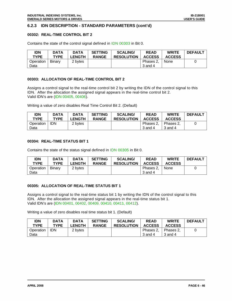
INDUSTRIAL INDEXING SYSTEMS, Inc. IB-21B001 EMERALD SERIES MOTORS & DRIVES USER’S GUIDE
APRIL 2008 PAGE 6 - 46
6.2.3 IDN DESCRIPTION - STANDARD PARAMETERS (cont’d) 00302: REAL-TIME CONTROL BIT 2 Contains the state of the control signal defined in IDN 00303 in Bit 0.
IDN TYPE
DATA TYPE
DATA LENGTH
SETTING RANGE
SCALING/ RESOLUTION
READ ACCESS
WRITE ACCESS
DEFAULT
Operation Data
Binary 2 bytes Phases 2, 3 and 4
None 0
00303: ALLOCATION OF REAL-TIME CONTROL BIT 2 Assigns a control signal to the real-time control bit 2 by writing the IDN of the control signal to this IDN. After the allocation the assigned signal appears in the real-time control bit 2. Valid IDN’s are (IDN 00405, 00406). Writing a value of zero disables Real Time Control Bit 2. (Default)
IDN TYPE
DATA TYPE
DATA LENGTH
SETTING RANGE
SCALING/ RESOLUTION
READ ACCESS
WRITE ACCESS
DEFAULT
Operation Data
IDN 2 bytes Phases 2, 3 and 4
Phases 2, 3 and 4
0
00304: REAL-TIME STATUS BIT 1 Contains the state of the status signal defined in IDN 00305 in Bit 0.
IDN TYPE
DATA TYPE
DATA LENGTH
SETTING RANGE
SCALING/ RESOLUTION
READ ACCESS
WRITE ACCESS
DEFAULT
Operation Data
Binary 2 bytes Phases 2, 3 and 4
None 0
00305: ALLOCATION OF REAL-TIME STATUS BIT 1 Assigns a control signal to the real-time status bit 1 by writing the IDN of the control signal to this IDN. After the allocation the assigned signal appears in the real-time status bit 1. Valid IDN’s are (IDN 00401, 00402, 00409, 00410, 00411, 00412). Writing a value of zero disables real time status bit 1. (Default)
IDN TYPE
DATA TYPE
DATA LENGTH
SETTING RANGE
SCALING/ RESOLUTION
READ ACCESS
WRITE ACCESS
DEFAULT
Operation Data
IDN 2 bytes Phases 2, 3 and 4
Phases 2, 3 and 4
0
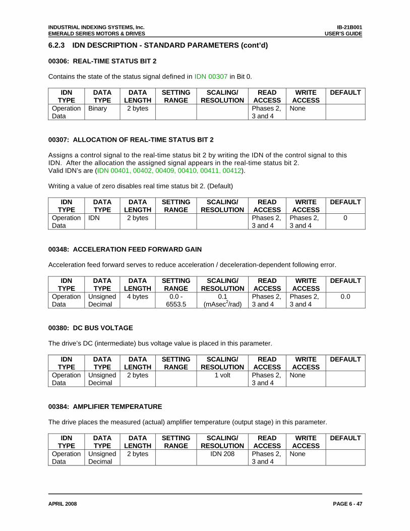
INDUSTRIAL INDEXING SYSTEMS, Inc. IB-21B001 EMERALD SERIES MOTORS & DRIVES USER’S GUIDE
APRIL 2008 PAGE 6 - 47
6.2.3 IDN DESCRIPTION - STANDARD PARAMETERS (cont’d) 00306: REAL-TIME STATUS BIT 2 Contains the state of the status signal defined in IDN 00307 in Bit 0.
IDN TYPE
DATA TYPE
DATA LENGTH
SETTING RANGE
SCALING/ RESOLUTION
READ ACCESS
WRITE ACCESS
DEFAULT
Operation Data
Binary 2 bytes Phases 2, 3 and 4
None
00307: ALLOCATION OF REAL-TIME STATUS BIT 2 Assigns a control signal to the real-time status bit 2 by writing the IDN of the control signal to this IDN. After the allocation the assigned signal appears in the real-time status bit 2. Valid IDN’s are (IDN 00401, 00402, 00409, 00410, 00411, 00412). Writing a value of zero disables real time status bit 2. (Default)
IDN TYPE
DATA TYPE
DATA LENGTH
SETTING RANGE
SCALING/ RESOLUTION
READ ACCESS
WRITE ACCESS
DEFAULT
Operation Data
IDN 2 bytes Phases 2, 3 and 4
Phases 2, 3 and 4
0
00348: ACCELERATION FEED FORWARD GAIN Acceleration feed forward serves to reduce acceleration / deceleration-dependent following error.
IDN TYPE
DATA TYPE
DATA LENGTH
SETTING RANGE
SCALING/ RESOLUTION
READ ACCESS
WRITE ACCESS
DEFAULT
Operation Data
Unsigned Decimal
4 bytes 0.0 - 6553.5
0.1 (mAsec2/rad)
Phases 2, 3 and 4
Phases 2, 3 and 4
0.0
00380: DC BUS VOLTAGE The drive’s DC (intermediate) bus voltage value is placed in this parameter.
IDN TYPE
DATA TYPE
DATA LENGTH
SETTING RANGE
SCALING/ RESOLUTION
READ ACCESS
WRITE ACCESS
DEFAULT
Operation Data
Unsigned Decimal
2 bytes 1 volt Phases 2, 3 and 4
None
00384: AMPLIFIER TEMPERATURE The drive places the measured (actual) amplifier temperature (output stage) in this parameter.
IDN TYPE
DATA TYPE
DATA LENGTH
SETTING RANGE
SCALING/ RESOLUTION
READ ACCESS
WRITE ACCESS
DEFAULT
Operation Data
Unsigned Decimal
2 bytes IDN 208 Phases 2, 3 and 4
None
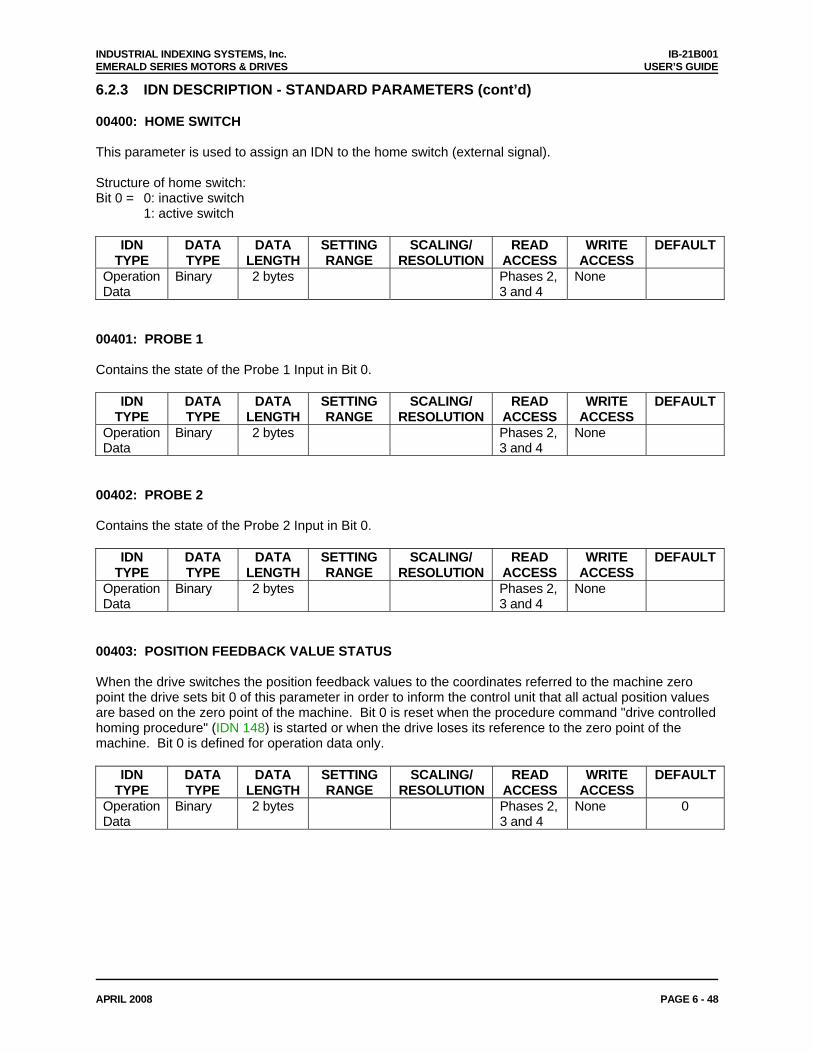
INDUSTRIAL INDEXING SYSTEMS, Inc. IB-21B001 EMERALD SERIES MOTORS & DRIVES USER’S GUIDE
APRIL 2008 PAGE 6 - 48
6.2.3 IDN DESCRIPTION - STANDARD PARAMETERS (cont’d) 00400: HOME SWITCH This parameter is used to assign an IDN to the home switch (external signal). Structure of home switch: Bit 0 = 0: inactive switch
1: active switch
IDN TYPE
DATA TYPE
DATA LENGTH
SETTING RANGE
SCALING/ RESOLUTION
READ ACCESS
WRITE ACCESS
DEFAULT
Operation Data
Binary 2 bytes Phases 2, 3 and 4
None
00401: PROBE 1 Contains the state of the Probe 1 Input in Bit 0.
IDN TYPE
DATA TYPE
DATA LENGTH
SETTING RANGE
SCALING/ RESOLUTION
READ ACCESS
WRITE ACCESS
DEFAULT
Operation Data
Binary 2 bytes Phases 2, 3 and 4
None
00402: PROBE 2 Contains the state of the Probe 2 Input in Bit 0.
IDN TYPE
DATA TYPE
DATA LENGTH
SETTING RANGE
SCALING/ RESOLUTION
READ ACCESS
WRITE ACCESS
DEFAULT
Operation Data
Binary 2 bytes Phases 2, 3 and 4
None
00403: POSITION FEEDBACK VALUE STATUS When the drive switches the position feedback values to the coordinates referred to the machine zero point the drive sets bit 0 of this parameter in order to inform the control unit that all actual position values are based on the zero point of the machine. Bit 0 is reset when the procedure command "drive controlled homing procedure" (IDN 148) is started or when the drive loses its reference to the zero point of the machine. Bit 0 is defined for operation data only.
IDN TYPE
DATA TYPE
DATA LENGTH
SETTING RANGE
SCALING/ RESOLUTION
READ ACCESS
WRITE ACCESS
DEFAULT
Operation Data
Binary 2 bytes Phases 2, 3 and 4
None 0
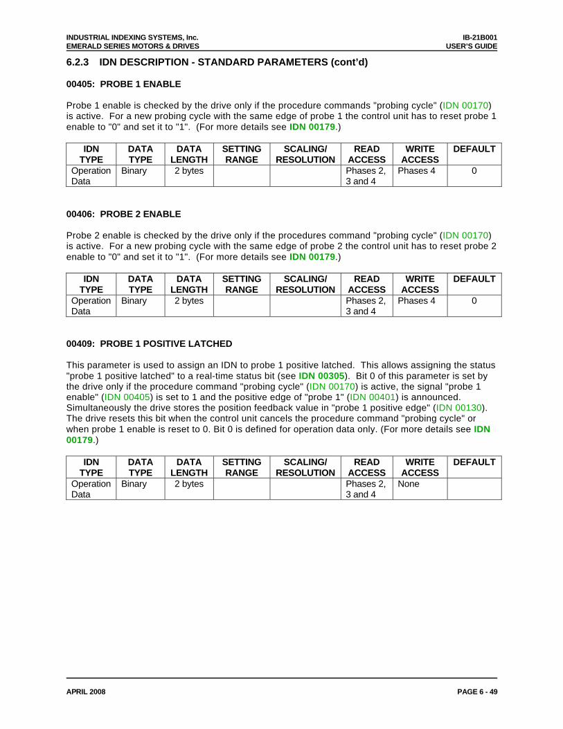
INDUSTRIAL INDEXING SYSTEMS, Inc. IB-21B001 EMERALD SERIES MOTORS & DRIVES USER’S GUIDE
APRIL 2008 PAGE 6 - 49
6.2.3 IDN DESCRIPTION - STANDARD PARAMETERS (cont’d) 00405: PROBE 1 ENABLE Probe 1 enable is checked by the drive only if the procedure commands "probing cycle" (IDN 00170) is active. For a new probing cycle with the same edge of probe 1 the control unit has to reset probe 1 enable to "0" and set it to "1". (For more details see IDN 00179.)
IDN TYPE
DATA TYPE
DATA LENGTH
SETTING RANGE
SCALING/ RESOLUTION
READ ACCESS
WRITE ACCESS
DEFAULT
Operation Data
Binary 2 bytes Phases 2, 3 and 4
Phases 4 0
00406: PROBE 2 ENABLE Probe 2 enable is checked by the drive only if the procedures command "probing cycle" (IDN 00170) is active. For a new probing cycle with the same edge of probe 2 the control unit has to reset probe 2 enable to "0" and set it to "1". (For more details see IDN 00179.)
IDN TYPE
DATA TYPE
DATA LENGTH
SETTING RANGE
SCALING/ RESOLUTION
READ ACCESS
WRITE ACCESS
DEFAULT
Operation Data
Binary 2 bytes Phases 2, 3 and 4
Phases 4 0
00409: PROBE 1 POSITIVE LATCHED This parameter is used to assign an IDN to probe 1 positive latched. This allows assigning the status "probe 1 positive latched" to a real-time status bit (see IDN 00305). Bit 0 of this parameter is set by the drive only if the procedure command "probing cycle" (IDN 00170) is active, the signal "probe 1 enable" (IDN 00405) is set to 1 and the positive edge of "probe 1" (IDN 00401) is announced. Simultaneously the drive stores the position feedback value in "probe 1 positive edge" (IDN 00130). The drive resets this bit when the control unit cancels the procedure command "probing cycle" or when probe 1 enable is reset to 0. Bit 0 is defined for operation data only. (For more details see IDN 00179.)
IDN TYPE
DATA TYPE
DATA LENGTH
SETTING RANGE
SCALING/ RESOLUTION
READ ACCESS
WRITE ACCESS
DEFAULT
Operation Data
Binary 2 bytes Phases 2, 3 and 4
None
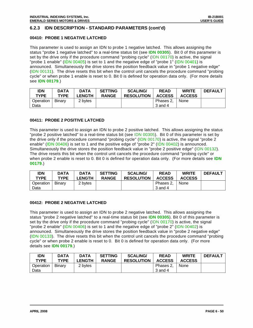
INDUSTRIAL INDEXING SYSTEMS, Inc. IB-21B001 EMERALD SERIES MOTORS & DRIVES USER’S GUIDE
APRIL 2008 PAGE 6 - 50
6.2.3 IDN DESCRIPTION - STANDARD PARAMETERS (cont’d) 00410: PROBE 1 NEGATIVE LATCHED This parameter is used to assign an IDN to probe 1 negative latched. This allows assigning the status "probe 1 negative latched" to a real-time status bit (see IDN 00305). Bit 0 of this parameter is set by the drive only if the procedure command "probing cycle" (IDN 00170) is active, the signal "probe 1 enable" (IDN 00405) is set to 1 and the negative edge of "probe 1" (IDN 00401) is announced. Simultaneously the drive stores the position feedback value in "probe 1 negative edge" (IDN 00131). The drive resets this bit when the control unit cancels the procedure command "probing cycle" or when probe 1 enable is reset to 0. Bit 0 is defined for operation data only. (For more details see IDN 00179.)
IDN TYPE
DATA TYPE
DATA LENGTH
SETTING RANGE
SCALING/ RESOLUTION
READ ACCESS
WRITE ACCESS
DEFAULT
Operation Data
Binary 2 bytes Phases 2, 3 and 4
None
00411: PROBE 2 POSITIVE LATCHED This parameter is used to assign an IDN to probe 2 positive latched. This allows assigning the status "probe 2 positive latched" to a real-time status bit (see IDN 00305). Bit 0 of this parameter is set by the drive only if the procedure command "probing cycle" (IDN 00170) is active, the signal "probe 2 enable" (IDN 00406) is set to 1 and the positive edge of "probe 2" (IDN 00402) is announced. Simultaneously the drive stores the position feedback value in "probe 2 positive edge" (IDN 00132). The drive resets this bit when the control unit cancels the procedure command "probing cycle" or when probe 2 enable is reset to 0. Bit 0 is defined for operation data only. (For more details see IDN 00179.)
IDN TYPE
DATA TYPE
DATA LENGTH
SETTING RANGE
SCALING/ RESOLUTION
READ ACCESS
WRITE ACCESS
DEFAULT
Operation Data
Binary 2 bytes Phases 2, 3 and 4
None
00412: PROBE 2 NEGATIVE LATCHED This parameter is used to assign an IDN to probe 2 negative latched. This allows assigning the status "probe 2 negative latched" to a real-time status bit (see IDN 00305). Bit 0 of this parameter is set by the drive only if the procedure command "probing cycle" (IDN 00170) is active, the signal "probe 2 enable" (IDN 00406) is set to 1 and the negative edge of "probe 2" (IDN 00402) is announced. Simultaneously the drive stores the position feedback value in "probe 2 negative edge" (IDN 00133). The drive resets this bit when the control unit cancels the procedure command "probing cycle" or when probe 2 enable is reset to 0. Bit 0 is defined for operation data only. (For more details see IDN 00179.)
IDN TYPE
DATA TYPE
DATA LENGTH
SETTING RANGE
SCALING/ RESOLUTION
READ ACCESS
WRITE ACCESS
DEFAULT
Operation Data
Binary 2 bytes Phases 2, 3 and 4
None
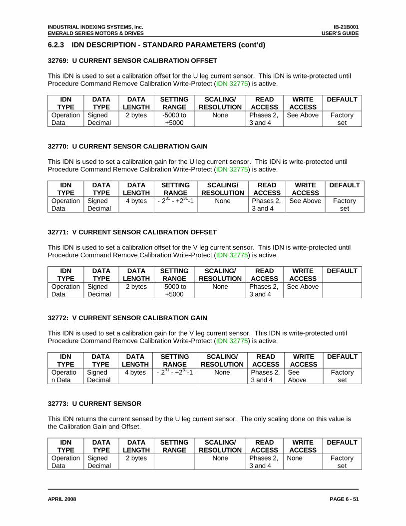
INDUSTRIAL INDEXING SYSTEMS, Inc. IB-21B001 EMERALD SERIES MOTORS & DRIVES USER’S GUIDE
APRIL 2008 PAGE 6 - 51
6.2.3 IDN DESCRIPTION - STANDARD PARAMETERS (cont’d) 32769: U CURRENT SENSOR CALIBRATION OFFSET This IDN is used to set a calibration offset for the U leg current sensor. This IDN is write-protected until Procedure Command Remove Calibration Write-Protect (IDN 32775) is active.
IDN TYPE
DATA TYPE
DATA LENGTH
SETTING RANGE
SCALING/ RESOLUTION
READ ACCESS
WRITE ACCESS
DEFAULT
Operation Data
Signed Decimal
2 bytes -5000 to +5000
None Phases 2, 3 and 4
See Above Factory set
32770: U CURRENT SENSOR CALIBRATION GAIN This IDN is used to set a calibration gain for the U leg current sensor. This IDN is write-protected until Procedure Command Remove Calibration Write-Protect (IDN 32775) is active.
IDN TYPE
DATA TYPE
DATA LENGTH
SETTING RANGE
SCALING/ RESOLUTION
READ ACCESS
WRITE ACCESS
DEFAULT
Operation Data
Signed Decimal
4 bytes - 231 - +231-1 None Phases 2, 3 and 4
See Above Factory set
32771: V CURRENT SENSOR CALIBRATION OFFSET This IDN is used to set a calibration offset for the V leg current sensor. This IDN is write-protected until Procedure Command Remove Calibration Write-Protect (IDN 32775) is active.
IDN TYPE
DATA TYPE
DATA LENGTH
SETTING RANGE
SCALING/ RESOLUTION
READ ACCESS
WRITE ACCESS
DEFAULT
Operation Data
Signed Decimal
2 bytes -5000 to +5000
None Phases 2, 3 and 4
See Above
32772: V CURRENT SENSOR CALIBRATION GAIN This IDN is used to set a calibration gain for the V leg current sensor. This IDN is write-protected until Procedure Command Remove Calibration Write-Protect (IDN 32775) is active.
IDN TYPE
DATA TYPE
DATA LENGTH
SETTING RANGE
SCALING/ RESOLUTION
READ ACCESS
WRITE ACCESS
DEFAULT
Operation Data
Signed Decimal
4 bytes - 231 - +231-1 None Phases 2, 3 and 4
See Above
Factory set
32773: U CURRENT SENSOR This IDN returns the current sensed by the U leg current sensor. The only scaling done on this value is the Calibration Gain and Offset.
IDN TYPE
DATA TYPE
DATA LENGTH
SETTING RANGE
SCALING/ RESOLUTION
READ ACCESS
WRITE ACCESS
DEFAULT
Operation Data
Signed Decimal
2 bytes None Phases 2, 3 and 4
None Factory set
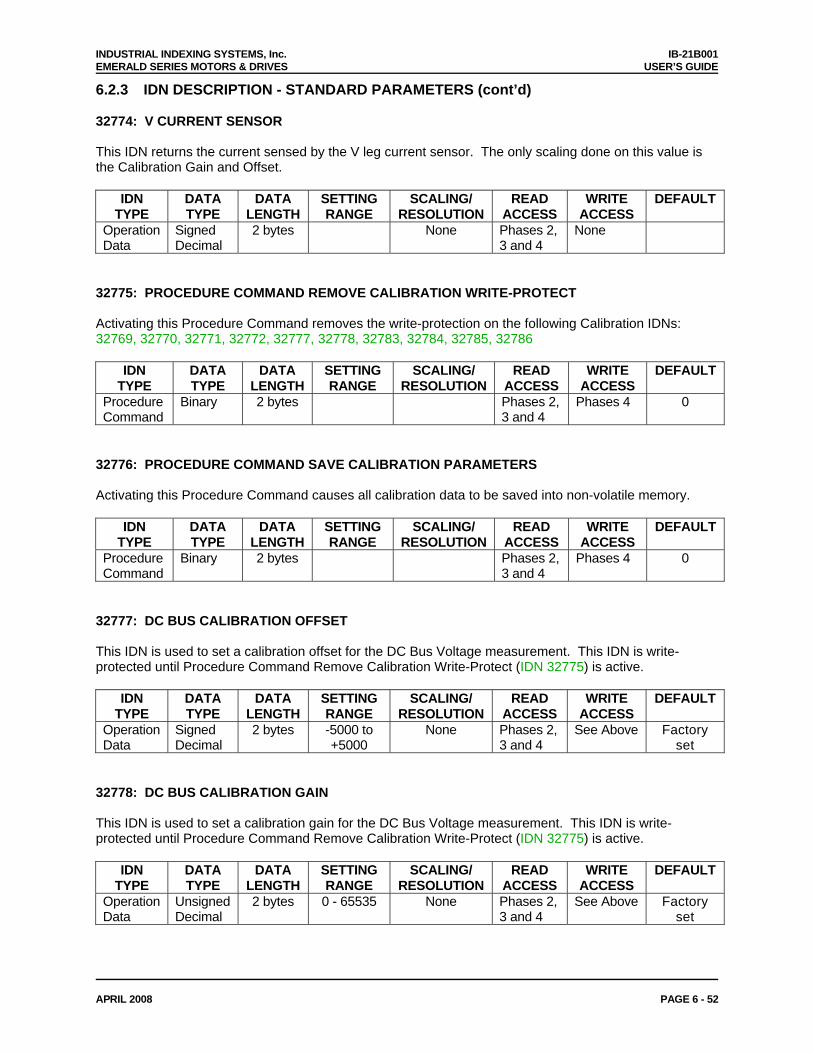
INDUSTRIAL INDEXING SYSTEMS, Inc. IB-21B001 EMERALD SERIES MOTORS & DRIVES USER’S GUIDE
APRIL 2008 PAGE 6 - 52
6.2.3 IDN DESCRIPTION - STANDARD PARAMETERS (cont’d) 32774: V CURRENT SENSOR This IDN returns the current sensed by the V leg current sensor. The only scaling done on this value is the Calibration Gain and Offset.
IDN TYPE
DATA TYPE
DATA LENGTH
SETTING RANGE
SCALING/ RESOLUTION
READ ACCESS
WRITE ACCESS
DEFAULT
Operation Data
Signed Decimal
2 bytes None Phases 2, 3 and 4
None
32775: PROCEDURE COMMAND REMOVE CALIBRATION WRITE-PROTECT Activating this Procedure Command removes the write-protection on the following Calibration IDNs: 32769, 32770, 32771, 32772, 32777, 32778, 32783, 32784, 32785, 32786
IDN TYPE
DATA TYPE
DATA LENGTH
SETTING RANGE
SCALING/ RESOLUTION
READ ACCESS
WRITE ACCESS
DEFAULT
Procedure Command
Binary 2 bytes Phases 2, 3 and 4
Phases 4 0
32776: PROCEDURE COMMAND SAVE CALIBRATION PARAMETERS Activating this Procedure Command causes all calibration data to be saved into non-volatile memory.
IDN TYPE
DATA TYPE
DATA LENGTH
SETTING RANGE
SCALING/ RESOLUTION
READ ACCESS
WRITE ACCESS
DEFAULT
Procedure Command
Binary 2 bytes Phases 2, 3 and 4
Phases 4 0
32777: DC BUS CALIBRATION OFFSET This IDN is used to set a calibration offset for the DC Bus Voltage measurement. This IDN is write-protected until Procedure Command Remove Calibration Write-Protect (IDN 32775) is active.
IDN TYPE
DATA TYPE
DATA LENGTH
SETTING RANGE
SCALING/ RESOLUTION
READ ACCESS
WRITE ACCESS
DEFAULT
Operation Data
Signed Decimal
2 bytes -5000 to +5000
None Phases 2, 3 and 4
See Above Factory set
32778: DC BUS CALIBRATION GAIN This IDN is used to set a calibration gain for the DC Bus Voltage measurement. This IDN is write-protected until Procedure Command Remove Calibration Write-Protect (IDN 32775) is active.
IDN TYPE
DATA TYPE
DATA LENGTH
SETTING RANGE
SCALING/ RESOLUTION
READ ACCESS
WRITE ACCESS
DEFAULT
Operation Data
Unsigned Decimal
2 bytes 0 - 65535 None Phases 2, 3 and 4
See Above Factory set
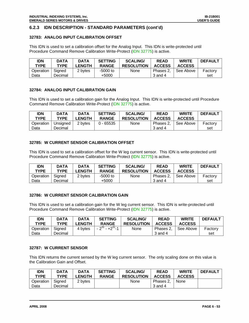
INDUSTRIAL INDEXING SYSTEMS, Inc. IB-21B001 EMERALD SERIES MOTORS & DRIVES USER’S GUIDE
APRIL 2008 PAGE 6 - 53
6.2.3 IDN DESCRIPTION - STANDARD PARAMETERS (cont’d) 32783: ANALOG INPUT CALIBRATION OFFSET This IDN is used to set a calibration offset for the Analog Input. This IDN is write-protected until Procedure Command Remove Calibration Write-Protect (IDN 32775) is active.
IDN TYPE
DATA TYPE
DATA LENGTH
SETTING RANGE
SCALING/ RESOLUTION
READ ACCESS
WRITE ACCESS
DEFAULT
Operation Data
Signed Decimal
2 bytes -5000 to +5000
None Phases 2, 3 and 4
See Above Factory set
32784: ANALOG INPUT CALIBRATION GAIN This IDN is used to set a calibration gain for the Analog Input. This IDN is write-protected until Procedure Command Remove Calibration Write-Protect (IDN 32775) is active.
IDN TYPE
DATA TYPE
DATA LENGTH
SETTING RANGE
SCALING/ RESOLUTION
READ ACCESS
WRITE ACCESS
DEFAULT
Operation Data
Unsigned Decimal
2 bytes 0 - 65535 None Phases 2, 3 and 4
See Above Factory set
32785: W CURRENT SENSOR CALIBRATION OFFSET This IDN is used to set a calibration offset for the W leg current sensor. This IDN is write-protected until Procedure Command Remove Calibration Write-Protect (IDN 32775) is active.
IDN TYPE
DATA TYPE
DATA LENGTH
SETTING RANGE
SCALING/ RESOLUTION
READ ACCESS
WRITE ACCESS
DEFAULT
Operation Data
Signed Decimal
2 bytes -5000 to +5000
None Phases 2, 3 and 4
See Above Factory set
32786: W CURRENT SENSOR CALIBRATION GAIN This IDN is used to set a calibration gain for the W leg current sensor. This IDN is write-protected until Procedure Command Remove Calibration Write-Protect (IDN 32775) is active.
IDN TYPE
DATA TYPE
DATA LENGTH
SETTING RANGE
SCALING/ RESOLUTION
READ ACCESS
WRITE ACCESS
DEFAULT
Operation Data
Signed Decimal
4 bytes - 231 - +231-1 None Phases 2, 3 and 4
See Above Factory set
32787: W CURRENT SENSOR This IDN returns the current sensed by the W leg current sensor. The only scaling done on this value is the Calibration Gain and Offset.
IDN TYPE
DATA TYPE
DATA LENGTH
SETTING RANGE
SCALING/ RESOLUTION
READ ACCESS
WRITE ACCESS
DEFAULT
Operation Data
Signed Decimal
2 bytes None Phases 2, 3 and 4
None
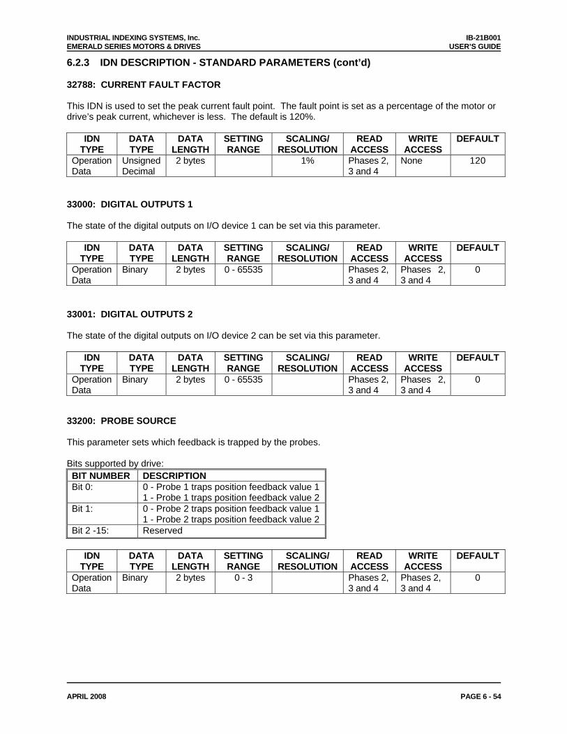
INDUSTRIAL INDEXING SYSTEMS, Inc. IB-21B001 EMERALD SERIES MOTORS & DRIVES USER’S GUIDE
APRIL 2008 PAGE 6 - 54
6.2.3 IDN DESCRIPTION - STANDARD PARAMETERS (cont’d) 32788: CURRENT FAULT FACTOR This IDN is used to set the peak current fault point. The fault point is set as a percentage of the motor or drive’s peak current, whichever is less. The default is 120%.
IDN TYPE
DATA TYPE
DATA LENGTH
SETTING RANGE
SCALING/ RESOLUTION
READ ACCESS
WRITE ACCESS
DEFAULT
Operation Data
Unsigned Decimal
2 bytes 1% Phases 2, 3 and 4
None 120
33000: DIGITAL OUTPUTS 1 The state of the digital outputs on I/O device 1 can be set via this parameter.
IDN TYPE
DATA TYPE
DATA LENGTH
SETTING RANGE
SCALING/ RESOLUTION
READ ACCESS
WRITE ACCESS
DEFAULT
Operation Data
Binary 2 bytes 0 - 65535 Phases 2, 3 and 4
Phases 2, 3 and 4
0
33001: DIGITAL OUTPUTS 2 The state of the digital outputs on I/O device 2 can be set via this parameter.
IDN TYPE
DATA TYPE
DATA LENGTH
SETTING RANGE
SCALING/ RESOLUTION
READ ACCESS
WRITE ACCESS
DEFAULT
Operation Data
Binary 2 bytes 0 - 65535 Phases 2, 3 and 4
Phases 2, 3 and 4
0
33200: PROBE SOURCE This parameter sets which feedback is trapped by the probes. Bits supported by drive: BIT NUMBER DESCRIPTION Bit 0: 0 - Probe 1 traps position feedback value 1
1 - Probe 1 traps position feedback value 2 Bit 1: 0 - Probe 2 traps position feedback value 1
1 - Probe 2 traps position feedback value 2 Bit 2 -15: Reserved
IDN
TYPE DATA TYPE
DATA LENGTH
SETTING RANGE
SCALING/ RESOLUTION
READ ACCESS
WRITE ACCESS
DEFAULT
Operation Data
Binary 2 bytes 0 - 3 Phases 2, 3 and 4
Phases 2, 3 and 4
0
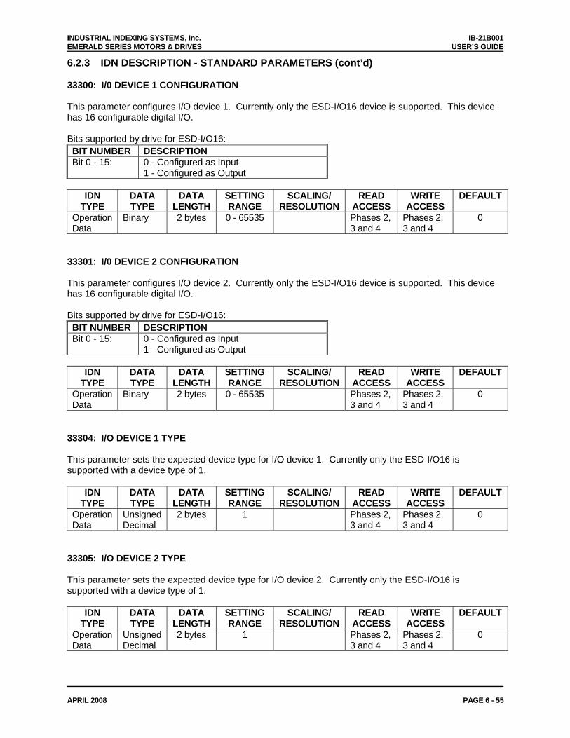
INDUSTRIAL INDEXING SYSTEMS, Inc. IB-21B001 EMERALD SERIES MOTORS & DRIVES USER’S GUIDE
APRIL 2008 PAGE 6 - 55
6.2.3 IDN DESCRIPTION - STANDARD PARAMETERS (cont’d) 33300: I/0 DEVICE 1 CONFIGURATION This parameter configures I/O device 1. Currently only the ESD-I/O16 device is supported. This device has 16 configurable digital I/O. Bits supported by drive for ESD-I/O16: BIT NUMBER DESCRIPTION Bit 0 - 15: 0 - Configured as Input
1 - Configured as Output
IDN TYPE
DATA TYPE
DATA LENGTH
SETTING RANGE
SCALING/ RESOLUTION
READ ACCESS
WRITE ACCESS
DEFAULT
Operation Data
Binary 2 bytes 0 - 65535 Phases 2, 3 and 4
Phases 2, 3 and 4
0
33301: I/0 DEVICE 2 CONFIGURATION This parameter configures I/O device 2. Currently only the ESD-I/O16 device is supported. This device has 16 configurable digital I/O. Bits supported by drive for ESD-I/O16: BIT NUMBER DESCRIPTION Bit 0 - 15: 0 - Configured as Input
1 - Configured as Output
IDN TYPE
DATA TYPE
DATA LENGTH
SETTING RANGE
SCALING/ RESOLUTION
READ ACCESS
WRITE ACCESS
DEFAULT
Operation Data
Binary 2 bytes 0 - 65535 Phases 2, 3 and 4
Phases 2, 3 and 4
0
33304: I/O DEVICE 1 TYPE This parameter sets the expected device type for I/O device 1. Currently only the ESD-I/O16 is supported with a device type of 1.
IDN TYPE
DATA TYPE
DATA LENGTH
SETTING RANGE
SCALING/ RESOLUTION
READ ACCESS
WRITE ACCESS
DEFAULT
Operation Data
Unsigned Decimal
2 bytes 1 Phases 2, 3 and 4
Phases 2, 3 and 4
0
33305: I/O DEVICE 2 TYPE This parameter sets the expected device type for I/O device 2. Currently only the ESD-I/O16 is supported with a device type of 1.
IDN TYPE
DATA TYPE
DATA LENGTH
SETTING RANGE
SCALING/ RESOLUTION
READ ACCESS
WRITE ACCESS
DEFAULT
Operation Data
Unsigned Decimal
2 bytes 1 Phases 2, 3 and 4
Phases 2, 3 and 4
0
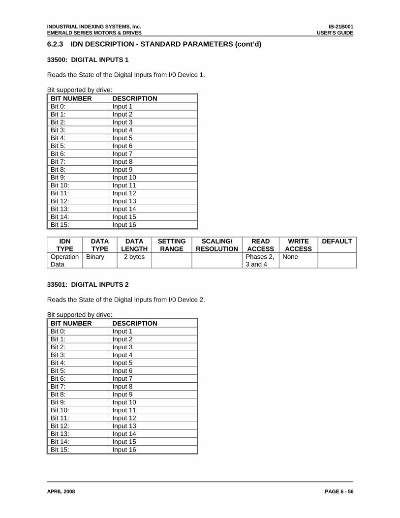
INDUSTRIAL INDEXING SYSTEMS, Inc. IB-21B001 EMERALD SERIES MOTORS & DRIVES USER’S GUIDE
APRIL 2008 PAGE 6 - 56
6.2.3 IDN DESCRIPTION - STANDARD PARAMETERS (cont’d) 33500: DIGITAL INPUTS 1 Reads the State of the Digital Inputs from I/0 Device 1. Bit supported by drive: BIT NUMBER DESCRIPTION Bit 0: Input 1 Bit 1: Input 2 Bit 2: Input 3 Bit 3: Input 4 Bit 4: Input 5 Bit 5: Input 6 Bit 6: Input 7 Bit 7: Input 8 Bit 8: Input 9 Bit 9: Input 10 Bit 10: Input 11 Bit 11: Input 12 Bit 12: Input 13 Bit 13: Input 14 Bit 14: Input 15 Bit 15: Input 16
IDN
TYPE DATA TYPE
DATA LENGTH
SETTING RANGE
SCALING/ RESOLUTION
READ ACCESS
WRITE ACCESS
DEFAULT
Operation Data
Binary 2 bytes Phases 2, 3 and 4
None
33501: DIGITAL INPUTS 2 Reads the State of the Digital Inputs from I/0 Device 2. Bit supported by drive: BIT NUMBER DESCRIPTION Bit 0: Input 1 Bit 1: Input 2 Bit 2: Input 3 Bit 3: Input 4 Bit 4: Input 5 Bit 5: Input 6 Bit 6: Input 7 Bit 7: Input 8 Bit 8: Input 9 Bit 9: Input 10 Bit 10: Input 11 Bit 11: Input 12 Bit 12: Input 13 Bit 13: Input 14 Bit 14: Input 15 Bit 15: Input 16
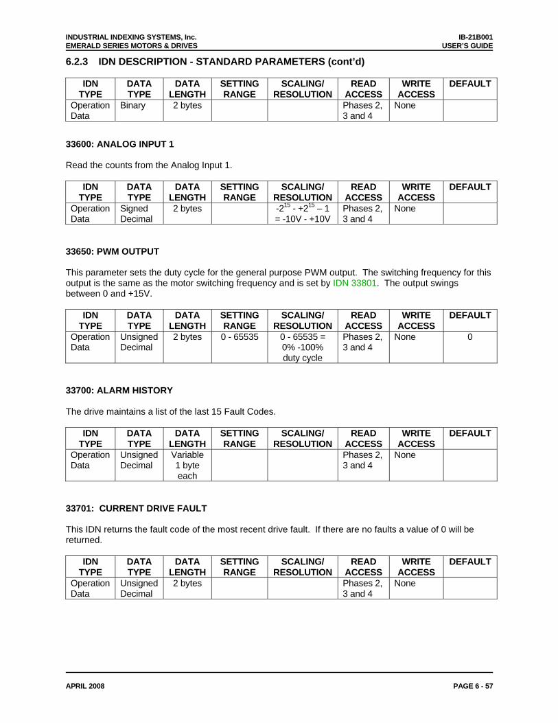
INDUSTRIAL INDEXING SYSTEMS, Inc. IB-21B001 EMERALD SERIES MOTORS & DRIVES USER’S GUIDE
APRIL 2008 PAGE 6 - 57
6.2.3 IDN DESCRIPTION - STANDARD PARAMETERS (cont’d)
IDN TYPE
DATA TYPE
DATA LENGTH
SETTING RANGE
SCALING/ RESOLUTION
READ ACCESS
WRITE ACCESS
DEFAULT
Operation Data
Binary 2 bytes Phases 2, 3 and 4
None
33600: ANALOG INPUT 1 Read the counts from the Analog Input 1.
IDN TYPE
DATA TYPE
DATA LENGTH
SETTING RANGE
SCALING/ RESOLUTION
READ ACCESS
WRITE ACCESS
DEFAULT
Operation Data
Signed Decimal
2 bytes -215 - +215 – 1 = -10V - +10V
Phases 2, 3 and 4
None
33650: PWM OUTPUT This parameter sets the duty cycle for the general purpose PWM output. The switching frequency for this output is the same as the motor switching frequency and is set by IDN 33801. The output swings between 0 and +15V.
IDN TYPE
DATA TYPE
DATA LENGTH
SETTING RANGE
SCALING/ RESOLUTION
READ ACCESS
WRITE ACCESS
DEFAULT
Operation Data
Unsigned Decimal
2 bytes 0 - 65535 0 - 65535 = 0% -100% duty cycle
Phases 2, 3 and 4
None 0
33700: ALARM HISTORY The drive maintains a list of the last 15 Fault Codes.
IDN TYPE
DATA TYPE
DATA LENGTH
SETTING RANGE
SCALING/ RESOLUTION
READ ACCESS
WRITE ACCESS
DEFAULT
Operation Data
Unsigned Decimal
Variable 1 byte each
Phases 2, 3 and 4
None
33701: CURRENT DRIVE FAULT This IDN returns the fault code of the most recent drive fault. If there are no faults a value of 0 will be returned.
IDN TYPE
DATA TYPE
DATA LENGTH
SETTING RANGE
SCALING/ RESOLUTION
READ ACCESS
WRITE ACCESS
DEFAULT
Operation Data
Unsigned Decimal
2 bytes Phases 2, 3 and 4
None
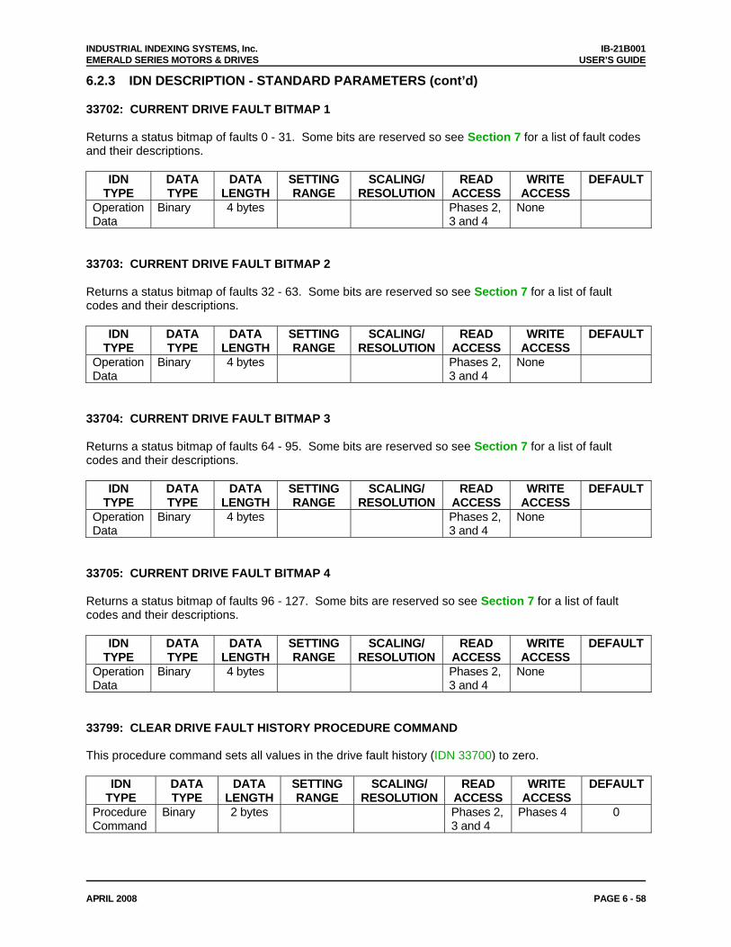
INDUSTRIAL INDEXING SYSTEMS, Inc. IB-21B001 EMERALD SERIES MOTORS & DRIVES USER’S GUIDE
APRIL 2008 PAGE 6 - 58
6.2.3 IDN DESCRIPTION - STANDARD PARAMETERS (cont’d) 33702: CURRENT DRIVE FAULT BITMAP 1 Returns a status bitmap of faults 0 - 31. Some bits are reserved so see Section 7 for a list of fault codes and their descriptions.
IDN TYPE
DATA TYPE
DATA LENGTH
SETTING RANGE
SCALING/ RESOLUTION
READ ACCESS
WRITE ACCESS
DEFAULT
Operation Data
Binary 4 bytes Phases 2, 3 and 4
None
33703: CURRENT DRIVE FAULT BITMAP 2 Returns a status bitmap of faults 32 - 63. Some bits are reserved so see Section 7 for a list of fault codes and their descriptions.
IDN TYPE
DATA TYPE
DATA LENGTH
SETTING RANGE
SCALING/ RESOLUTION
READ ACCESS
WRITE ACCESS
DEFAULT
Operation Data
Binary 4 bytes Phases 2, 3 and 4
None
33704: CURRENT DRIVE FAULT BITMAP 3 Returns a status bitmap of faults 64 - 95. Some bits are reserved so see Section 7 for a list of fault codes and their descriptions.
IDN TYPE
DATA TYPE
DATA LENGTH
SETTING RANGE
SCALING/ RESOLUTION
READ ACCESS
WRITE ACCESS
DEFAULT
Operation Data
Binary 4 bytes Phases 2, 3 and 4
None
33705: CURRENT DRIVE FAULT BITMAP 4 Returns a status bitmap of faults 96 - 127. Some bits are reserved so see Section 7 for a list of fault codes and their descriptions.
IDN TYPE
DATA TYPE
DATA LENGTH
SETTING RANGE
SCALING/ RESOLUTION
READ ACCESS
WRITE ACCESS
DEFAULT
Operation Data
Binary 4 bytes Phases 2, 3 and 4
None
33799: CLEAR DRIVE FAULT HISTORY PROCEDURE COMMAND This procedure command sets all values in the drive fault history (IDN 33700) to zero.
IDN TYPE
DATA TYPE
DATA LENGTH
SETTING RANGE
SCALING/ RESOLUTION
READ ACCESS
WRITE ACCESS
DEFAULT
Procedure Command
Binary 2 bytes Phases 2, 3 and 4
Phases 4 0
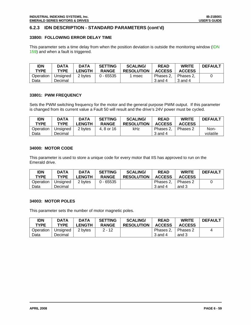
INDUSTRIAL INDEXING SYSTEMS, Inc. IB-21B001 EMERALD SERIES MOTORS & DRIVES USER’S GUIDE
APRIL 2008 PAGE 6 - 59
6.2.3 IDN DESCRIPTION - STANDARD PARAMETERS (cont’d) 33800: FOLLOWING ERROR DELAY TIME This parameter sets a time delay from when the position deviation is outside the monitoring window (IDN 159) and when a fault is triggered.
IDN TYPE
DATA TYPE
DATA LENGTH
SETTING RANGE
SCALING/ RESOLUTION
READ ACCESS
WRITE ACCESS
DEFAULT
Operation Data
Unsigned Decimal
2 bytes 0 - 65535 1 msec Phases 2, 3 and 4
Phases 2, 3 and 4
0
33801: PWM FREQUENCY Sets the PWM switching frequency for the motor and the general purpose PWM output. If this parameter is changed from its current value a Fault 50 will result and the drive’s 24V power must be cycled.
IDN TYPE
DATA TYPE
DATA LENGTH
SETTING RANGE
SCALING/ RESOLUTION
READ ACCESS
WRITE ACCESS
DEFAULT
Operation Data
Unsigned Decimal
2 bytes 4, 8 or 16 kHz Phases 2, 3 and 4
Phases 2 Non-volatile
34000: MOTOR CODE This parameter is used to store a unique code for every motor that IIS has approved to run on the Emerald drive.
IDN TYPE
DATA TYPE
DATA LENGTH
SETTING RANGE
SCALING/ RESOLUTION
READ ACCESS
WRITE ACCESS
DEFAULT
Operation Data
Unsigned Decimal
2 bytes 0 - 65535 Phases 2, 3 and 4
Phases 2 and 3
0
34003: MOTOR POLES This parameter sets the number of motor magnetic poles.
IDN TYPE
DATA TYPE
DATA LENGTH
SETTING RANGE
SCALING/ RESOLUTION
READ ACCESS
WRITE ACCESS
DEFAULT
Operation Data
Unsigned Decimal
2 bytes 2 - 12 Phases 2, 3 and 4
Phases 2 and 3
4
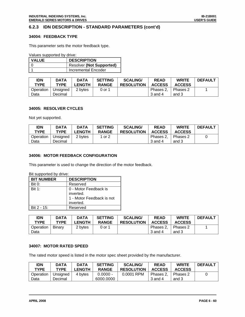
INDUSTRIAL INDEXING SYSTEMS, Inc. IB-21B001 EMERALD SERIES MOTORS & DRIVES USER’S GUIDE
APRIL 2008 PAGE 6 - 60
6.2.3 IDN DESCRIPTION - STANDARD PARAMETERS (cont’d) 34004: FEEDBACK TYPE This parameter sets the motor feedback type. Values supported by drive: VALUE DESCRIPTION 0 Resolver (Not Supported) 1 Incremental Encoder
IDN
TYPE DATA TYPE
DATA LENGTH
SETTING RANGE
SCALING/ RESOLUTION
READ ACCESS
WRITE ACCESS
DEFAULT
Operation Data
Unsigned Decimal
2 bytes 0 or 1 Phases 2, 3 and 4
Phases 2 and 3
1
34005: RESOLVER CYCLES Not yet supported.
IDN TYPE
DATA TYPE
DATA LENGTH
SETTING RANGE
SCALING/ RESOLUTION
READ ACCESS
WRITE ACCESS
DEFAULT
Operation Data
Unsigned Decimal
2 bytes 1 or 2 Phases 2, 3 and 4
Phases 2 and 3
0
34006: MOTOR FEEDBACK CONFIGURATION This parameter is used to change the direction of the motor feedback. Bit supported by drive: BIT NUMBER DESCRIPTION Bit 0: Reserved Bit 1: 0 - Motor Feedback is
inverted. 1 - Motor Feedback is not inverted.
Bit 2 - 15: Reserved
IDN TYPE
DATA TYPE
DATA LENGTH
SETTING RANGE
SCALING/ RESOLUTION
READ ACCESS
WRITE ACCESS
DEFAULT
Operation Data
Binary 2 bytes 0 or 1 Phases 2, 3 and 4
Phases 2 and 3
1
34007: MOTOR RATED SPEED The rated motor speed is listed in the motor spec sheet provided by the manufacturer.
IDN TYPE
DATA TYPE
DATA LENGTH
SETTING RANGE
SCALING/ RESOLUTION
READ ACCESS
WRITE ACCESS
DEFAULT
Operation Data
Unsigned Decimal
4 bytes 0.0000 - 6000.0000
0.0001 RPM Phases 2, 3 and 4
Phases 2 and 3
0
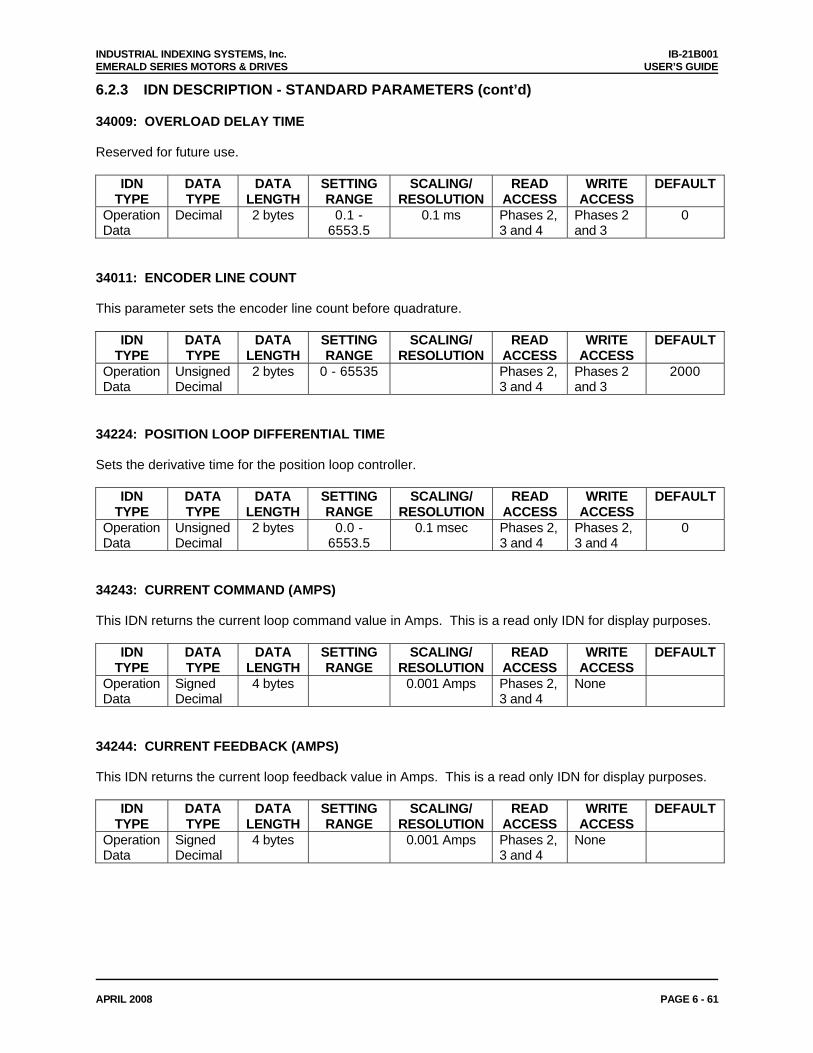
INDUSTRIAL INDEXING SYSTEMS, Inc. IB-21B001 EMERALD SERIES MOTORS & DRIVES USER’S GUIDE
APRIL 2008 PAGE 6 - 61
6.2.3 IDN DESCRIPTION - STANDARD PARAMETERS (cont’d) 34009: OVERLOAD DELAY TIME Reserved for future use.
IDN TYPE
DATA TYPE
DATA LENGTH
SETTING RANGE
SCALING/ RESOLUTION
READ ACCESS
WRITE ACCESS
DEFAULT
Operation Data
Decimal 2 bytes 0.1 - 6553.5
0.1 ms Phases 2, 3 and 4
Phases 2 and 3
0
34011: ENCODER LINE COUNT This parameter sets the encoder line count before quadrature.
IDN TYPE
DATA TYPE
DATA LENGTH
SETTING RANGE
SCALING/ RESOLUTION
READ ACCESS
WRITE ACCESS
DEFAULT
Operation Data
Unsigned Decimal
2 bytes 0 - 65535 Phases 2, 3 and 4
Phases 2 and 3
2000
34224: POSITION LOOP DIFFERENTIAL TIME Sets the derivative time for the position loop controller.
IDN TYPE
DATA TYPE
DATA LENGTH
SETTING RANGE
SCALING/ RESOLUTION
READ ACCESS
WRITE ACCESS
DEFAULT
Operation Data
Unsigned Decimal
2 bytes 0.0 - 6553.5
0.1 msec Phases 2, 3 and 4
Phases 2, 3 and 4
0
34243: CURRENT COMMAND (AMPS) This IDN returns the current loop command value in Amps. This is a read only IDN for display purposes.
IDN TYPE
DATA TYPE
DATA LENGTH
SETTING RANGE
SCALING/ RESOLUTION
READ ACCESS
WRITE ACCESS
DEFAULT
Operation Data
Signed Decimal
4 bytes 0.001 Amps Phases 2, 3 and 4
None
34244: CURRENT FEEDBACK (AMPS) This IDN returns the current loop feedback value in Amps. This is a read only IDN for display purposes.
IDN TYPE
DATA TYPE
DATA LENGTH
SETTING RANGE
SCALING/ RESOLUTION
READ ACCESS
WRITE ACCESS
DEFAULT
Operation Data
Signed Decimal
4 bytes 0.001 Amps Phases 2, 3 and 4
None
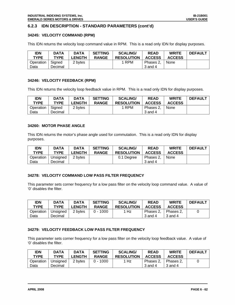
INDUSTRIAL INDEXING SYSTEMS, Inc. IB-21B001 EMERALD SERIES MOTORS & DRIVES USER’S GUIDE
APRIL 2008 PAGE 6 - 62
6.2.3 IDN DESCRIPTION - STANDARD PARAMETERS (cont’d) 34245: VELOCITY COMMAND (RPM) This IDN returns the velocity loop command value in RPM. This is a read only IDN for display purposes.
IDN TYPE
DATA TYPE
DATA LENGTH
SETTING RANGE
SCALING/ RESOLUTION
READ ACCESS
WRITE ACCESS
DEFAULT
Operation Data
Signed Decimal
2 bytes 1 RPM Phases 2, 3 and 4
None
34246: VELOCITY FEEDBACK (RPM) This IDN returns the velocity loop feedback value in RPM. This is a read only IDN for display purposes.
IDN TYPE
DATA TYPE
DATA LENGTH
SETTING RANGE
SCALING/ RESOLUTION
READ ACCESS
WRITE ACCESS
DEFAULT
Operation Data
Signed Decimal
2 bytes 1 RPM Phases 2, 3 and 4
None
34260: MOTOR PHASE ANGLE This IDN returns the motor’s phase angle used for commutation. This is a read only IDN for display purposes.
IDN TYPE
DATA TYPE
DATA LENGTH
SETTING RANGE
SCALING/ RESOLUTION
READ ACCESS
WRITE ACCESS
DEFAULT
Operation Data
Unsigned Decimal
2 bytes 0.1 Degree Phases 2, 3 and 4
None
34278: VELOCITY COMMAND LOW PASS FILTER FREQUENCY This parameter sets corner frequency for a low pass filter on the velocity loop command value. A value of ‘0’ disables the filter.
IDN TYPE
DATA TYPE
DATA LENGTH
SETTING RANGE
SCALING/ RESOLUTION
READ ACCESS
WRITE ACCESS
DEFAULT
Operation Data
Unsigned Decimal
2 bytes 0 - 1000 1 Hz Phases 2, 3 and 4
Phases 2, 3 and 4
0
34279: VELOCITY FEEDBACK LOW PASS FILTER FREQUENCY This parameter sets corner frequency for a low pass filter on the velocity loop feedback value. A value of ‘0’ disables the filter.
IDN TYPE
DATA TYPE
DATA LENGTH
SETTING RANGE
SCALING/ RESOLUTION
READ ACCESS
WRITE ACCESS
DEFAULT
Operation Data
Unsigned Decimal
2 bytes 0 - 1000 1 Hz Phases 2, 3 and 4
Phases 2, 3 and 4
0
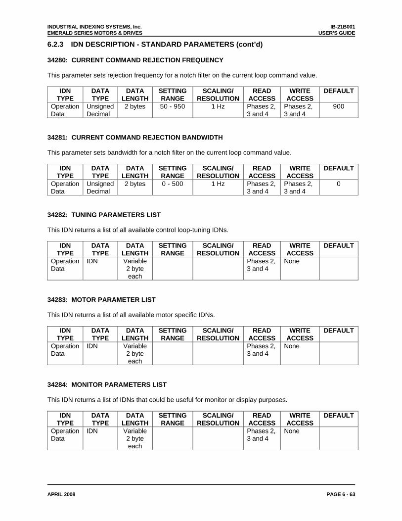
INDUSTRIAL INDEXING SYSTEMS, Inc. IB-21B001 EMERALD SERIES MOTORS & DRIVES USER’S GUIDE
APRIL 2008 PAGE 6 - 63
6.2.3 IDN DESCRIPTION - STANDARD PARAMETERS (cont’d) 34280: CURRENT COMMAND REJECTION FREQUENCY This parameter sets rejection frequency for a notch filter on the current loop command value.
IDN TYPE
DATA TYPE
DATA LENGTH
SETTING RANGE
SCALING/ RESOLUTION
READ ACCESS
WRITE ACCESS
DEFAULT
Operation Data
Unsigned Decimal
2 bytes 50 - 950 1 Hz Phases 2, 3 and 4
Phases 2, 3 and 4
900
34281: CURRENT COMMAND REJECTION BANDWIDTH This parameter sets bandwidth for a notch filter on the current loop command value.
IDN TYPE
DATA TYPE
DATA LENGTH
SETTING RANGE
SCALING/ RESOLUTION
READ ACCESS
WRITE ACCESS
DEFAULT
Operation Data
Unsigned Decimal
2 bytes 0 - 500 1 Hz Phases 2, 3 and 4
Phases 2, 3 and 4
0
34282: TUNING PARAMETERS LIST This IDN returns a list of all available control loop-tuning IDNs.
IDN TYPE
DATA TYPE
DATA LENGTH
SETTING RANGE
SCALING/ RESOLUTION
READ ACCESS
WRITE ACCESS
DEFAULT
Operation Data
IDN Variable 2 byte each
Phases 2, 3 and 4
None
34283: MOTOR PARAMETER LIST This IDN returns a list of all available motor specific IDNs.
IDN TYPE
DATA TYPE
DATA LENGTH
SETTING RANGE
SCALING/ RESOLUTION
READ ACCESS
WRITE ACCESS
DEFAULT
Operation Data
IDN Variable 2 byte each
Phases 2, 3 and 4
None
34284: MONITOR PARAMETERS LIST This IDN returns a list of IDNs that could be useful for monitor or display purposes.
IDN TYPE
DATA TYPE
DATA LENGTH
SETTING RANGE
SCALING/ RESOLUTION
READ ACCESS
WRITE ACCESS
DEFAULT
Operation Data
IDN Variable 2 byte each
Phases 2, 3 and 4
None
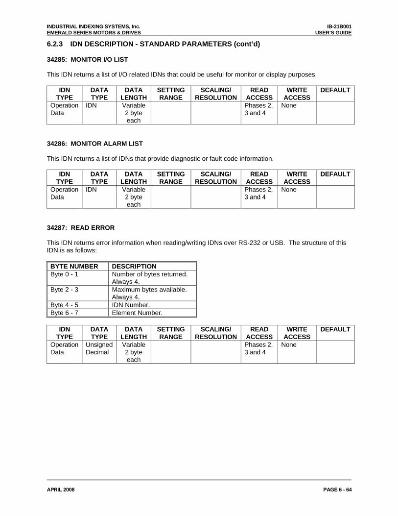
INDUSTRIAL INDEXING SYSTEMS, Inc. IB-21B001 EMERALD SERIES MOTORS & DRIVES USER’S GUIDE
APRIL 2008 PAGE 6 - 64
6.2.3 IDN DESCRIPTION - STANDARD PARAMETERS (cont’d) 34285: MONITOR I/O LIST This IDN returns a list of I/O related IDNs that could be useful for monitor or display purposes.
IDN TYPE
DATA TYPE
DATA LENGTH
SETTING RANGE
SCALING/ RESOLUTION
READ ACCESS
WRITE ACCESS
DEFAULT
Operation Data
IDN Variable 2 byte each
Phases 2, 3 and 4
None
34286: MONITOR ALARM LIST This IDN returns a list of IDNs that provide diagnostic or fault code information.
IDN TYPE
DATA TYPE
DATA LENGTH
SETTING RANGE
SCALING/ RESOLUTION
READ ACCESS
WRITE ACCESS
DEFAULT
Operation Data
IDN Variable 2 byte each
Phases 2, 3 and 4
None
34287: READ ERROR This IDN returns error information when reading/writing IDNs over RS-232 or USB. The structure of this IDN is as follows: BYTE NUMBER DESCRIPTION Byte 0 - 1 Number of bytes returned.
Always 4. Byte 2 - 3 Maximum bytes available.
Always 4. Byte 4 - 5 IDN Number. Byte 6 - 7 Element Number.
IDN
TYPE DATA TYPE
DATA LENGTH
SETTING RANGE
SCALING/ RESOLUTION
READ ACCESS
WRITE ACCESS
DEFAULT
Operation Data
Unsigned Decimal
Variable 2 byte each
Phases 2, 3 and 4
None
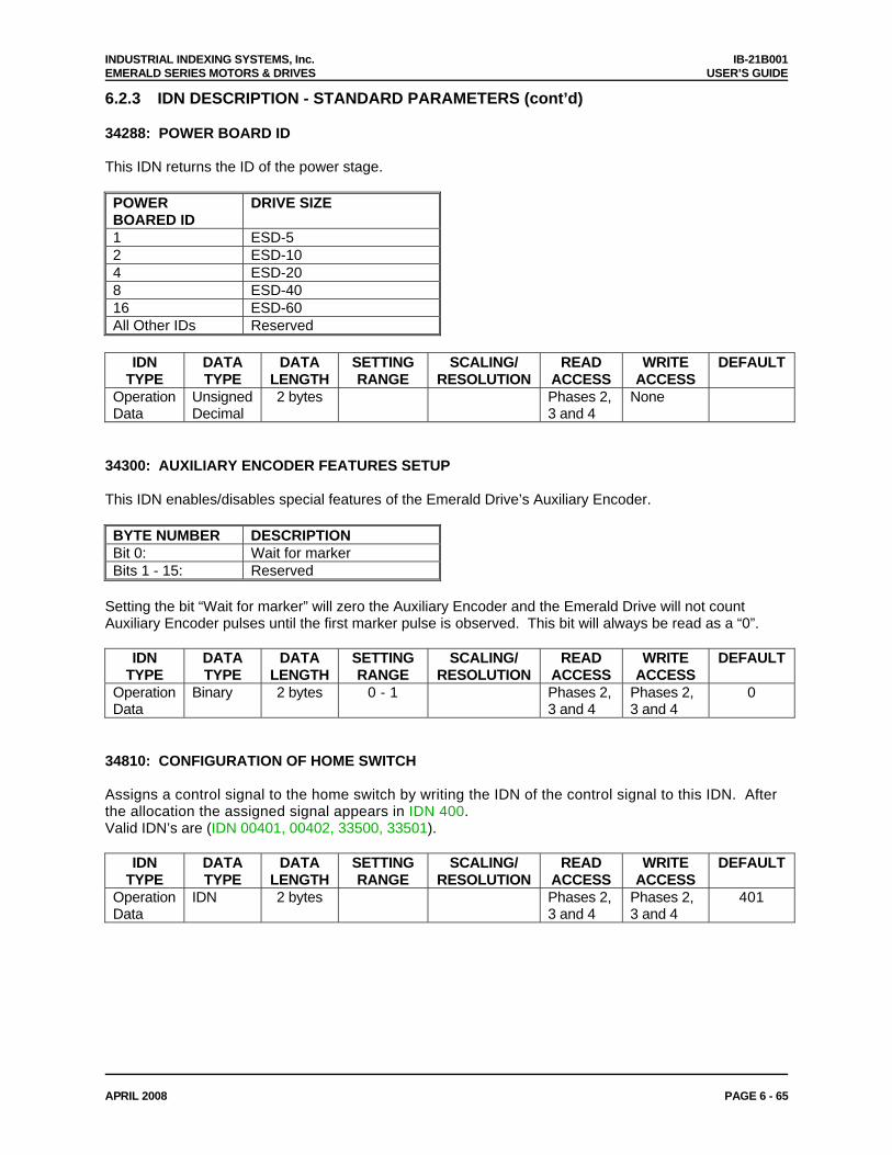
INDUSTRIAL INDEXING SYSTEMS, Inc. IB-21B001 EMERALD SERIES MOTORS & DRIVES USER’S GUIDE
APRIL 2008 PAGE 6 - 65
6.2.3 IDN DESCRIPTION - STANDARD PARAMETERS (cont’d) 34288: POWER BOARD ID This IDN returns the ID of the power stage. POWER BOARED ID
DRIVE SIZE
1 ESD-5 2 ESD-10 4 ESD-20 8 ESD-40 16 ESD-60 All Other IDs Reserved
IDN
TYPE DATA TYPE
DATA LENGTH
SETTING RANGE
SCALING/ RESOLUTION
READ ACCESS
WRITE ACCESS
DEFAULT
Operation Data
Unsigned Decimal
2 bytes Phases 2, 3 and 4
None
34300: AUXILIARY ENCODER FEATURES SETUP This IDN enables/disables special features of the Emerald Drive’s Auxiliary Encoder. BYTE NUMBER DESCRIPTION Bit 0: Wait for marker Bits 1 - 15: Reserved
Setting the bit “Wait for marker” will zero the Auxiliary Encoder and the Emerald Drive will not count Auxiliary Encoder pulses until the first marker pulse is observed. This bit will always be read as a “0”.
IDN TYPE
DATA TYPE
DATA LENGTH
SETTING RANGE
SCALING/ RESOLUTION
READ ACCESS
WRITE ACCESS
DEFAULT
Operation Data
Binary 2 bytes 0 - 1 Phases 2, 3 and 4
Phases 2, 3 and 4
0
34810: CONFIGURATION OF HOME SWITCH Assigns a control signal to the home switch by writing the IDN of the control signal to this IDN. After the allocation the assigned signal appears in IDN 400. Valid IDN’s are (IDN 00401, 00402, 33500, 33501).
IDN TYPE
DATA TYPE
DATA LENGTH
SETTING RANGE
SCALING/ RESOLUTION
READ ACCESS
WRITE ACCESS
DEFAULT
Operation Data
IDN 2 bytes Phases 2, 3 and 4
Phases 2, 3 and 4
401
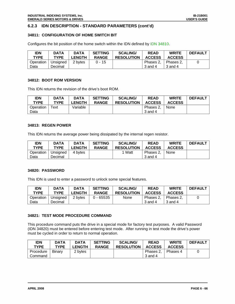
INDUSTRIAL INDEXING SYSTEMS, Inc. IB-21B001 EMERALD SERIES MOTORS & DRIVES USER’S GUIDE
APRIL 2008 PAGE 6 - 66
6.2.3 IDN DESCRIPTION - STANDARD PARAMETERS (cont’d) 34811: CONFIGURATION OF HOME SWITCH BIT Configures the bit position of the home switch within the IDN defined by IDN 34810.
IDN TYPE
DATA TYPE
DATA LENGTH
SETTING RANGE
SCALING/ RESOLUTION
READ ACCESS
WRITE ACCESS
DEFAULT
Operation Data
Unsigned Decimal
2 bytes 0 - 15 Phases 2, 3 and 4
Phases 2, 3 and 4
0
34812: BOOT ROM VERSION This IDN returns the revision of the drive’s boot ROM.
IDN TYPE
DATA TYPE
DATA LENGTH
SETTING RANGE
SCALING/ RESOLUTION
READ ACCESS
WRITE ACCESS
DEFAULT
Operation Data
Text Variable Phases 2, 3 and 4
None
34813: REGEN POWER This IDN returns the average power being dissipated by the internal regen resistor.
IDN TYPE
DATA TYPE
DATA LENGTH
SETTING RANGE
SCALING/ RESOLUTION
READ ACCESS
WRITE ACCESS
DEFAULT
Operation Data
Unsigned Decimal
4 bytes 1 Watt Phases 2, 3 and 4
None
34820: PASSWORD This IDN is used to enter a password to unlock some special features.
IDN TYPE
DATA TYPE
DATA LENGTH
SETTING RANGE
SCALING/ RESOLUTION
READ ACCESS
WRITE ACCESS
DEFAULT
Operation Data
Unsigned Decimal
2 bytes 0 - 65535 None Phases 2, 3 and 4
Phases 2, 3 and 4
0
34821: TEST MODE PROCEDURE COMMAND This procedure command puts the drive in a special mode for factory test purposes. A valid Password (IDN 34820) must be entered before entering test mode. After running in test mode the drive’s power must be cycled in order to return to normal operation.
IDN TYPE
DATA TYPE
DATA LENGTH
SETTING RANGE
SCALING/ RESOLUTION
READ ACCESS
WRITE ACCESS
DEFAULT
Procedure Command
Binary 2 bytes Phases 2, 3 and 4
Phases 4 0
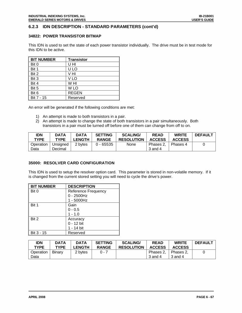
INDUSTRIAL INDEXING SYSTEMS, Inc. IB-21B001 EMERALD SERIES MOTORS & DRIVES USER’S GUIDE
APRIL 2008 PAGE 6 - 67
6.2.3 IDN DESCRIPTION - STANDARD PARAMETERS (cont’d) 34822: POWER TRANSISTOR BITMAP This IDN is used to set the state of each power transistor individually. The drive must be in test mode for this IDN to be active. BIT NUMBER Transistor Bit 0 U HI Bit 1 U LO Bit 2 V HI Bit 3 V LO Bit 4 W HI Bit 5 W LO Bit 6 REGEN Bit 7 - 15 Reserved
An error will be generated if the following conditions are met:
1) An attempt is made to both transistors in a pair. 2) An attempt is made to change the state of both transistors in a pair simultaneously. Both
transistors in a pair must be turned off before one of them can change from off to on.
IDN TYPE
DATA TYPE
DATA LENGTH
SETTING RANGE
SCALING/ RESOLUTION
READ ACCESS
WRITE ACCESS
DEFAULT
Operation Data
Unsigned Decimal
2 bytes 0 - 65535 None Phases 2, 3 and 4
Phases 4 0
35000: RESOLVER CARD CONFIGURATION This IDN is used to setup the resolver option card. This parameter is stored in non-volatile memory. If it is changed from the current stored setting you will need to cycle the drive’s power. BIT NUMBER DESCRIPTION Bit 0 Reference Frequency
0 - 2500Hz 1 - 5000Hz
Bit 1 Gain 0 - 0.5 1 - 1.0
Bit 2 Accuracy 0 - 12 bit 1 - 14 bit
Bit 3 - 15 Reserved
IDN TYPE
DATA TYPE
DATA LENGTH
SETTING RANGE
SCALING/ RESOLUTION
READ ACCESS
WRITE ACCESS
DEFAULT
Operation Data
Binary 2 bytes 0 - 7 Phases 2, 3 and 4
Phases 2, 3 and 4
0
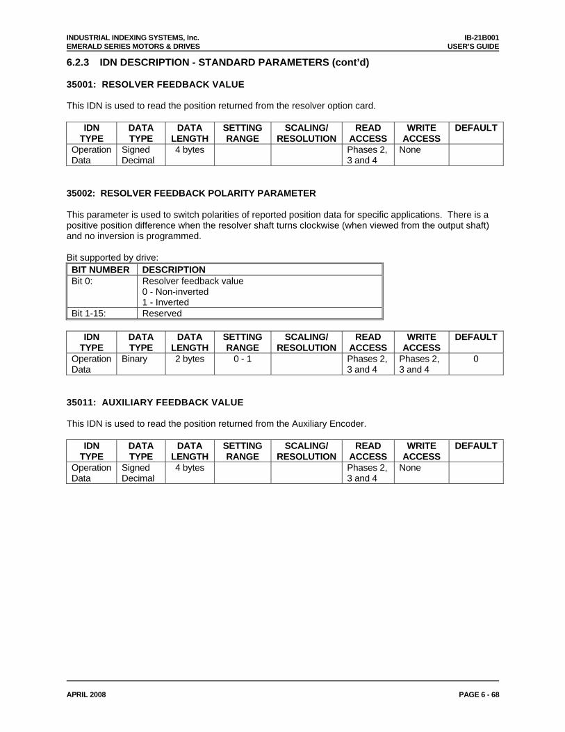
INDUSTRIAL INDEXING SYSTEMS, Inc. IB-21B001 EMERALD SERIES MOTORS & DRIVES USER’S GUIDE
APRIL 2008 PAGE 6 - 68
6.2.3 IDN DESCRIPTION - STANDARD PARAMETERS (cont’d) 35001: RESOLVER FEEDBACK VALUE This IDN is used to read the position returned from the resolver option card.
IDN TYPE
DATA TYPE
DATA LENGTH
SETTING RANGE
SCALING/ RESOLUTION
READ ACCESS
WRITE ACCESS
DEFAULT
Operation Data
Signed Decimal
4 bytes Phases 2, 3 and 4
None
35002: RESOLVER FEEDBACK POLARITY PARAMETER This parameter is used to switch polarities of reported position data for specific applications. There is a positive position difference when the resolver shaft turns clockwise (when viewed from the output shaft) and no inversion is programmed. Bit supported by drive: BIT NUMBER DESCRIPTION Bit 0: Resolver feedback value
0 - Non-inverted 1 - Inverted
Bit 1-15: Reserved
IDN TYPE
DATA TYPE
DATA LENGTH
SETTING RANGE
SCALING/ RESOLUTION
READ ACCESS
WRITE ACCESS
DEFAULT
Operation Data
Binary 2 bytes 0 - 1 Phases 2, 3 and 4
Phases 2, 3 and 4
0
35011: AUXILIARY FEEDBACK VALUE This IDN is used to read the position returned from the Auxiliary Encoder.
IDN TYPE
DATA TYPE
DATA LENGTH
SETTING RANGE
SCALING/ RESOLUTION
READ ACCESS
WRITE ACCESS
DEFAULT
Operation Data
Signed Decimal
4 bytes Phases 2, 3 and 4
None
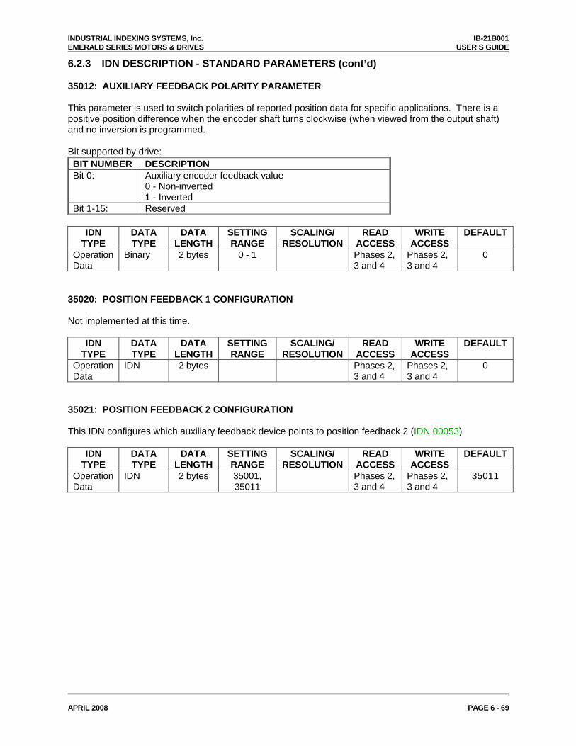
INDUSTRIAL INDEXING SYSTEMS, Inc. IB-21B001 EMERALD SERIES MOTORS & DRIVES USER’S GUIDE
APRIL 2008 PAGE 6 - 69
6.2.3 IDN DESCRIPTION - STANDARD PARAMETERS (cont’d) 35012: AUXILIARY FEEDBACK POLARITY PARAMETER This parameter is used to switch polarities of reported position data for specific applications. There is a positive position difference when the encoder shaft turns clockwise (when viewed from the output shaft) and no inversion is programmed. Bit supported by drive: BIT NUMBER DESCRIPTION Bit 0: Auxiliary encoder feedback value
0 - Non-inverted 1 - Inverted
Bit 1-15: Reserved
IDN TYPE
DATA TYPE
DATA LENGTH
SETTING RANGE
SCALING/ RESOLUTION
READ ACCESS
WRITE ACCESS
DEFAULT
Operation Data
Binary 2 bytes 0 - 1 Phases 2, 3 and 4
Phases 2, 3 and 4
0
35020: POSITION FEEDBACK 1 CONFIGURATION Not implemented at this time.
IDN TYPE
DATA TYPE
DATA LENGTH
SETTING RANGE
SCALING/ RESOLUTION
READ ACCESS
WRITE ACCESS
DEFAULT
Operation Data
IDN 2 bytes Phases 2, 3 and 4
Phases 2, 3 and 4
0
35021: POSITION FEEDBACK 2 CONFIGURATION This IDN configures which auxiliary feedback device points to position feedback 2 (IDN 00053)
IDN TYPE
DATA TYPE
DATA LENGTH
SETTING RANGE
SCALING/ RESOLUTION
READ ACCESS
WRITE ACCESS
DEFAULT
Operation Data
IDN 2 bytes 35001, 35011
Phases 2, 3 and 4
Phases 2, 3 and 4
35011
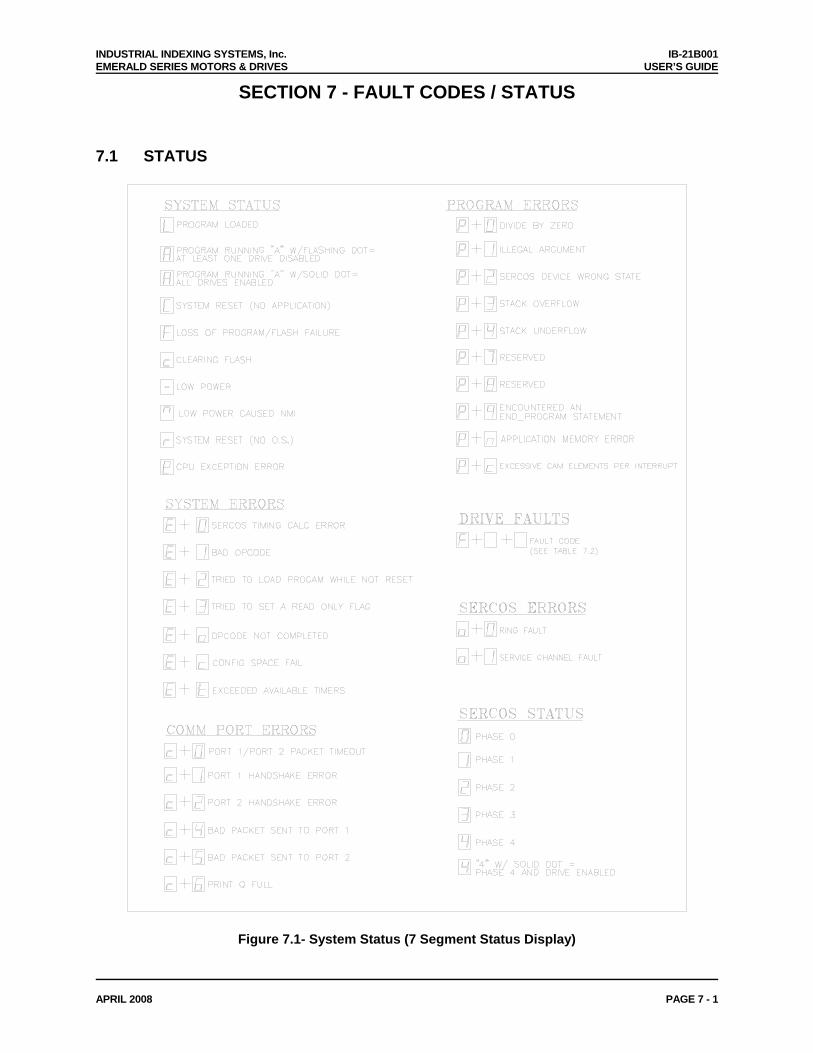
INDUSTRIAL INDEXING SYSTEMS, Inc. IB-21B001 EMERALD SERIES MOTORS & DRIVES USER’S GUIDE
APRIL 2008 PAGE 7 - 1
SECTION 7 - FAULT CODES / STATUS
7.1 STATUS
Figure 7.1- System Status (7 Segment Status Display)
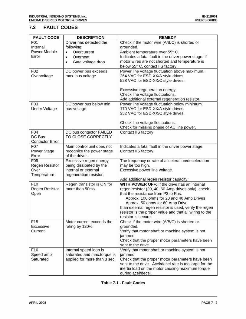
INDUSTRIAL INDEXING SYSTEMS, Inc. IB-21B001 EMERALD SERIES MOTORS & DRIVES USER’S GUIDE
APRIL 2008 PAGE 7 - 2
7.2 FAULT CODES
FAULT CODE DESCRIPTION REMEDY F01 Internal Power Module Error
Driver has detected the following: • Overcurrent • Overheat • Gate voltage drop
Check if the motor wire (A/B/C) is shorted or grounded. Ambient temperature over 55° C. Indicates a fatal fault in the driver power stage. If motor wires are not shorted and temperature is below 55° C, contact IIS factory.
F02 Overvoltage
DC power bus exceeds max. bus voltage.
Power line voltage fluctuation above maximum. 264 VAC for ESD-XX/A style drives. 528 VAC for ESD-XX/C style drives. Excessive regeneration energy. Check line voltage fluctuations. Add additional external regeneration resistor.
F03 Under Voltage
DC power bus below min. bus voltage.
Power line voltage fluctuation below minimum. 170 VAC for ESD-XX/A style drives. 352 VAC for ESD-XX/C style drives. Check line voltage fluctuations. Check for missing phase of AC line power.
F04 DC Bus Contactor Error
DC bus contactor FAILED TO CLOSE CORRECTLY
Contact IIS factory
F07 Power Stage Error
Main control unit does not recognize the power stage of the driver.
Indicates a fatal fault in the driver power stage. Contact IIS factory.
F09 Regen Resistor Over Temperature
Excessive regen energy being dissipated by the internal or external regeneration resistor.
The frequency or rate of acceleration/deceleration may be too high. Excessive power line voltage. Add additional regen resistor capacity.
F10 Regen Resistor Open
Regen transistor is ON for more than 50ms.
WITH POWER OFF: If the drive has an internal regen resistor (20, 40, 60 Amp drives only), check that the resistance from P3 to R is: Approx. 100 ohms for 20 and 40 Amp Drives Approx. 50 ohms for 60 Amp Drive If an external regen resistor is used, verify the regen resistor is the proper value and that all wiring to the resistor is secure.
F15 Excessive Current
Motor current exceeds the rating by 120%.
Check if the motor wire (A/B/C) is shorted or grounded. Verify that motor shaft or machine system is not jammed. Check that the proper motor parameters have been sent to the drive.
F16 Speed amp Saturated
Internal speed loop is saturated and max.torque is applied for more than 3 sec.
Verify that motor shaft or machine system is not jammed. Check that the proper motor parameters have been sent to the drive. Acel/decel rate is too large for the inertia load on the motor causing maximum torque during acel/decel.
Table 7.1 - Fault Codes
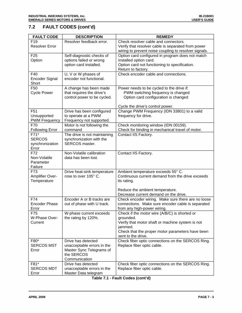
INDUSTRIAL INDEXING SYSTEMS, Inc. IB-21B001 EMERALD SERIES MOTORS & DRIVES USER’S GUIDE
APRIL 2009 PAGE 7 - 3
7.2 FAULT CODES (cont’d)
FAULT CODE DESCRIPTION REMEDY F19 Resolver Error
Resolver feedback error. Check resolver cable and connectors. Verify that resolver cable is separated from power wiring to prevent noise coupling to resolver signals.
F25 Option
Self-diagnostic checks of options failed or wrong option card installed.
Option card configured in program does not match installed option card. Option card not functioning to specification. Return to factory.
F40 Encoder Signal Short
U, V or W phases of encoder not functional.
Check encoder cable and connections.
F50 Cycle Power
A change has been made that requires the drive’s control power to be cycled.
Power needs to be cycled to the drive if: PWM switching frequency is changed Option card configuration is changed Cycle the drive’s control power.
F51 Unsupported PWM Frequency
Drive has been configured to operate at a PWM Frequency not supported.
Change PWM Frequency (IDN 33801) to a valid frequency for drive.
F70 Following Error
Motor is not following the command
Check monitoring window (IDN 00159). Check for binding in mechanical travel of motor.
F71* SERCOS synchronization Error
The drive is not maintaining synchronization with the SERCOS master.
Contact IIS Factory.
F72 Non-Volatile Parameter Failure
Non-Volatile calibration data has been lost.
Contact IIS Factory.
F73 Amplifier Over-Temperature
Drive heat-sink temperature rose to over 105° C.
Ambient temperature exceeds 55° C. Continuous current demand from the drive exceeds its rating. Reduce the ambient temperature. Decrease current demand on the drive.
F74 Encoder Phase Error
Encoder A or B tracks are out of phase with U track.
Check encoder wiring. Make sure there are no loose connections. Make sure encoder cable is separated from any high-power wiring.
F75 W-Phase Over-Current
W-phase current exceeds the rating by 120%.
Check if the motor wire (A/B/C) is shorted or grounded. Verify that motor shaft or machine system is not jammed. Check that the proper motor parameters have been sent to the drive.
F80* SERCOS MST Error
Drive has detected unacceptable errors in the Master Sync Telegrams of the SERCOS Communication
Check fiber optic connections on the SERCOS Ring. Replace fiber optic cable.
F81* SERCOS MDT Error
Drive has detected unacceptable errors in the Master Data telegram
Check fiber optic connections on the SERCOS Ring. Replace fiber optic cable.
Table 7.1 - Fault Codes (cont’d)
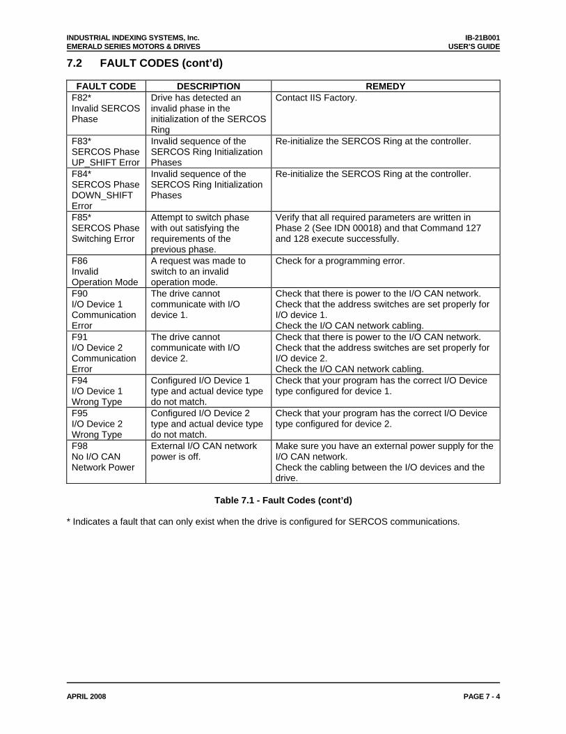
INDUSTRIAL INDEXING SYSTEMS, Inc. IB-21B001 EMERALD SERIES MOTORS & DRIVES USER’S GUIDE
APRIL 2008 PAGE 7 - 4
7.2 FAULT CODES (cont’d)
FAULT CODE DESCRIPTION REMEDY F82* Invalid SERCOS Phase
Drive has detected an invalid phase in the initialization of the SERCOS Ring
Contact IIS Factory.
F83* SERCOS Phase UP_SHIFT Error
Invalid sequence of the SERCOS Ring Initialization Phases
Re-initialize the SERCOS Ring at the controller.
F84* SERCOS Phase DOWN_SHIFT Error
Invalid sequence of the SERCOS Ring Initialization Phases
Re-initialize the SERCOS Ring at the controller.
F85* SERCOS Phase Switching Error
Attempt to switch phase with out satisfying the requirements of the previous phase.
Verify that all required parameters are written in Phase 2 (See IDN 00018) and that Command 127 and 128 execute successfully.
F86 Invalid Operation Mode
A request was made to switch to an invalid operation mode.
Check for a programming error.
F90 I/O Device 1 Communication Error
The drive cannot communicate with I/O device 1.
Check that there is power to the I/O CAN network. Check that the address switches are set properly for I/O device 1. Check the I/O CAN network cabling.
F91 I/O Device 2 Communication Error
The drive cannot communicate with I/O device 2.
Check that there is power to the I/O CAN network. Check that the address switches are set properly for I/O device 2. Check the I/O CAN network cabling.
F94 I/O Device 1 Wrong Type
Configured I/O Device 1 type and actual device type do not match.
Check that your program has the correct I/O Device type configured for device 1.
F95 I/O Device 2 Wrong Type
Configured I/O Device 2 type and actual device type do not match.
Check that your program has the correct I/O Device type configured for device 2.
F98 No I/O CAN Network Power
External I/O CAN network power is off.
Make sure you have an external power supply for the I/O CAN network. Check the cabling between the I/O devices and the drive.
Table 7.1 - Fault Codes (cont’d)
* Indicates a fault that can only exist when the drive is configured for SERCOS communications.
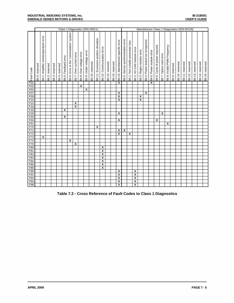
INDUSTRIAL INDEXING SYSTEMS, Inc. IB-21B001 EMERALD SERIES MOTORS & DRIVES USER’S GUIDE
APRIL 2009 PAGE 7 - 5
Fa
ult C
ode
Bit
0: re
serv
ed
Bit
1: A
mpl
ifier
ove
rtem
pera
ture
err
or
Bit
2: re
serv
ed
Bit
3: re
serv
ed
Bit
4: re
serv
ed
Bit
5: F
eedb
ack
erro
r
Bit
6: E
rror
in th
e "c
omm
utat
ion"
sys
tem
Bit
7: O
ver c
urre
nt e
rror
Bit
8: O
ver v
olta
ge e
rror
Bit
9: U
nder
vol
tage
err
or
Bit
10: r
eser
ved
Bit
11: E
xces
sive
pos
ition
dev
iatio
n
Bit
12: C
omm
unic
atio
n E
rror
Bit
13: r
eser
ved
Bit
14: r
eser
ved
Bit
15: M
anuf
actu
rer-
spec
ific
erro
r
Bit
0: S
erco
s sy
nchr
oniz
atio
n er
ror
Bit
1: N
on-v
olat
ile p
aram
eter
loss
Bit
2: I/
O C
AN
net
wor
k er
ror
Bit
3: R
egen
resi
stor
err
or
Bit
4: P
ower
boa
rd n
ot re
cogn
ized
Bit
5: P
ower
mod
ule
erro
r
Bit
6: C
ycle
of p
ower
requ
ired
Bit
7: O
ptio
n ca
rd e
rror
Bit
8: In
valid
PW
M F
requ
ency
Bit
9: re
serv
ed
Bit
10: r
eser
ved
Bit
11: r
eser
ved
Bit
12: r
eser
ved
Bit
13: r
eser
ved
Bit
14: r
eser
ved
Bit
15: r
eser
ved
F01 X XF02 XF03 XF07 X XF09 X XF10 X XF15 XF16 XF19 XF25 X XF40 XF50 X XF51 XF70 XF71 X XF72 X XF73 XF74 XF75 XF80 XF81 XF82 XF83 XF84 XF85 XF86 XF90 X XF91 X XF94 X XF95 X XF98 X X
Class 1 Diagnostics (IDN 00011) Manufacturer Class 1 Diagnostics (IDN 00129)
Table 7.2 - Cross Reference of Fault Codes to Class 1 Diagnostics
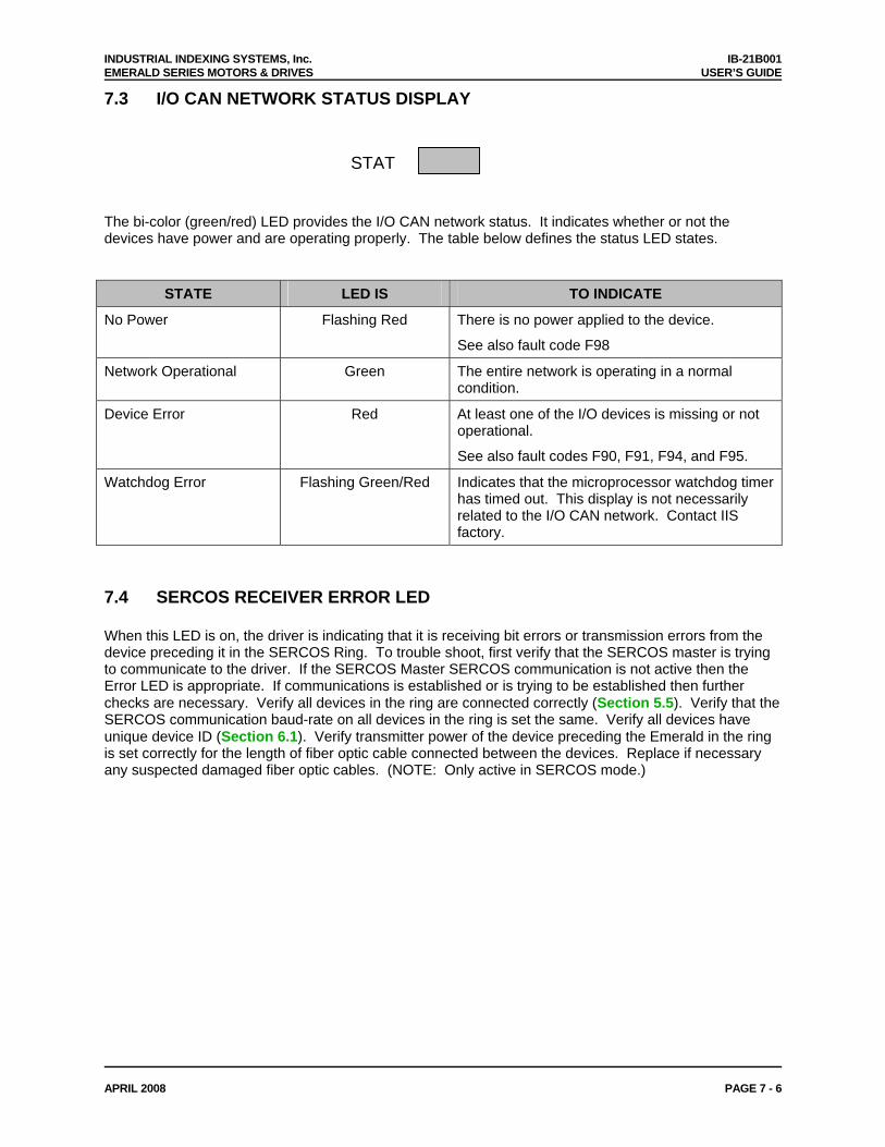
INDUSTRIAL INDEXING SYSTEMS, Inc. IB-21B001 EMERALD SERIES MOTORS & DRIVES USER’S GUIDE
APRIL 2008 PAGE 7 - 6
7.3 I/O CAN NETWORK STATUS DISPLAY
STAT
The bi-color (green/red) LED provides the I/O CAN network status. It indicates whether or not the devices have power and are operating properly. The table below defines the status LED states.
STATE LED IS TO INDICATE
No Power Flashing Red There is no power applied to the device.
See also fault code F98
Network Operational Green The entire network is operating in a normal condition.
Device Error Red At least one of the I/O devices is missing or not operational.
See also fault codes F90, F91, F94, and F95.
Watchdog Error Flashing Green/Red Indicates that the microprocessor watchdog timer has timed out. This display is not necessarily related to the I/O CAN network. Contact IIS factory.
7.4 SERCOS RECEIVER ERROR LED When this LED is on, the driver is indicating that it is receiving bit errors or transmission errors from the device preceding it in the SERCOS Ring. To trouble shoot, first verify that the SERCOS master is trying to communicate to the driver. If the SERCOS Master SERCOS communication is not active then the Error LED is appropriate. If communications is established or is trying to be established then further checks are necessary. Verify all devices in the ring are connected correctly (Section 5.5). Verify that the SERCOS communication baud-rate on all devices in the ring is set the same. Verify all devices have unique device ID (Section 6.1). Verify transmitter power of the device preceding the Emerald in the ring is set correctly for the length of fiber optic cable connected between the devices. Replace if necessary any suspected damaged fiber optic cables. (NOTE: Only active in SERCOS mode.)
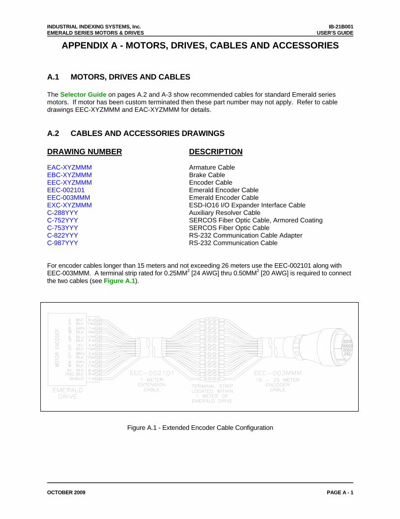
INDUSTRIAL INDEXING SYSTEMS, Inc. IB-21B001 EMERALD SERIES MOTORS & DRIVES USER’S GUIDE
OCTOBER 2009 PAGE A - 1
APPENDIX A - MOTORS, DRIVES, CABLES AND ACCESSORIES
A.1 MOTORS, DRIVES AND CABLES The Selector Guide on pages A.2 and A-3 show recommended cables for standard Emerald series motors. If motor has been custom terminated then these part number may not apply. Refer to cable drawings EEC-XYZMMM and EAC-XYZMMM for details. A.2 CABLES AND ACCESSORIES DRAWINGS DRAWING NUMBER DESCRIPTION EAC-XYZMMM Armature Cable EBC-XYZMMM Brake Cable EEC-XYZMMM Encoder Cable EEC-002101 Emerald Encoder Cable EEC-003MMM Emerald Encoder Cable EXC-XYZMMM ESD-IO16 I/O Expander Interface Cable C-288YYY Auxiliary Resolver Cable C-752YYY SERCOS Fiber Optic Cable, Armored Coating C-753YYY SERCOS Fiber Optic Cable C-822YYY RS-232 Communication Cable Adapter C-987YYY RS-232 Communication Cable For encoder cables longer than 15 meters and not exceeding 26 meters use the EEC-002101 along with EEC-003MMM. A terminal strip rated for 0.25MM2 [24 AWG] thru 0.50MM2 [20 AWG] is required to connect the two cables (see Figure A.1).
Figure A.1 - Extended Encoder Cable Configuration
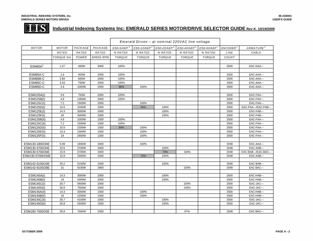
INDUSTRIAL INDEXING SYSTEMS, Inc.EMERALD SERIES MOTORS DRIVES
IB-21B001USER'S GUIDE
Industrial Indexing Systems Inc: EMERALD SERIES MOTOR/DRIVE SELECTOR GUIDE Rev K. 10/19/2009
Emerald Drives -- at nominal 220VAC line voltage
MOTOR MOTOR PACKAGE PACKAGE ESD-5/AEP 3 ESD-10/AEP 4 ESD-20/AEP 5 ESD-40/AEP 6 ESD-60/AEP 7 ENCODER 1 ARMATURE 2
RATED RATED RATED % RATED % RATED % RATED % RATED % RATED LINE CABLE
TORQUE Nm POWER SPEED RPM TORQUE TORQUE TORQUE TORQUE TORQUE COUNT
ESM60A1 1.27 400W 3000 100% 2500 EAC-DAA---
ESM85A-C 1.9 400W 2000 100% 2500 EAC-AAA---ESM85B-C 2.84 600W 2000 100% 2500 EAC-AAA---ESM85C-C 3.53 750W 2000 100% 2500 EAC-AAA---ESM85D-C 4.8 1000W 2000 96% 100% 2500 EAC-AAA---
ESM125A(I) 3.6 750W 2000 100% 2500 EAC-FAA---ESM125B(I) 4.8 1000W 2000 100% 2500 EAC-FAA---ESM125C(I) 7.2 1500W 2000 100% 2500 EAC-FAA---ESM125D(I) 10.5 2200W 2000 94% 100% 2500 EAC-FAA---/EAC-FAB---ESM125E(I) 14.3 3000W 2000 100% 2500 EAC-FAB---ESM125F(I) 19 4000W 2000 100% 2500 EAC-FAB---ESM125B(II) 4.8 1000W 1500 100% 2500 EAC-FAA---ESM125C(II) 7.2 1500W 1500 100% 2500 EAC-FAA---ESM125D(II) 10.5 2200W 1500 94% 100% 2500 EAC-FAA---ESM125E(II) 14.3 2300W 1500 100% 2500 EAC-FAA---ESM125F(II) 19 2600W 1300 100% 2500 EAC-FAA---
ESM130-1800/34E 5.09 1800W 3400 100% 2048 EAC-AAA---ESM130-3700/34E 10.5 3700W 3400 100% 2048 EAC-AAB---ESM130-5700/34E 15.9 5700W 3400 70% 100% 2048 EAC-BAB---/EAC-BAC---
ESM130-5700H/34E 15.9 3300W 2000 70% 100% 2048 EAC-AAB---
ESM142-5100/24E 20.2 5100W 2400 100% 2048 EAC-BAB---ESM142-9100/28E 31 9100W 2800 100% 2048 EAC-BAC---
ESM145A(I) 14.3 3000W 2000 100% 2500 EAC-HAB---ESM145B(I) 19 4000W 2000 100% 2500 EAC-HAB---ESM145C(I) 26.7 5600W 2000 100% 2500 EAC-JAC---ESM145D(I) 35.8 7500W 2000 100% 2500 EAC-JAC---ESM145A(II) 14.3 3000W 1500 100% 2500 EAC-HAB---ESM145B(II) 19 2200W 1500 100% 2500 EAC-HAB---ESM145C(II) 26.7 4100W 1500 100% 2500 EAC-JAC---ESM145D(II) 35.8 5500W 1500 100% 2500 EAC-JAC---
ESM180-7500/20E 35.8 7500W 2000 97% 2048 EAC-BAC---
OCTOBER 2009 PAGE A - 2
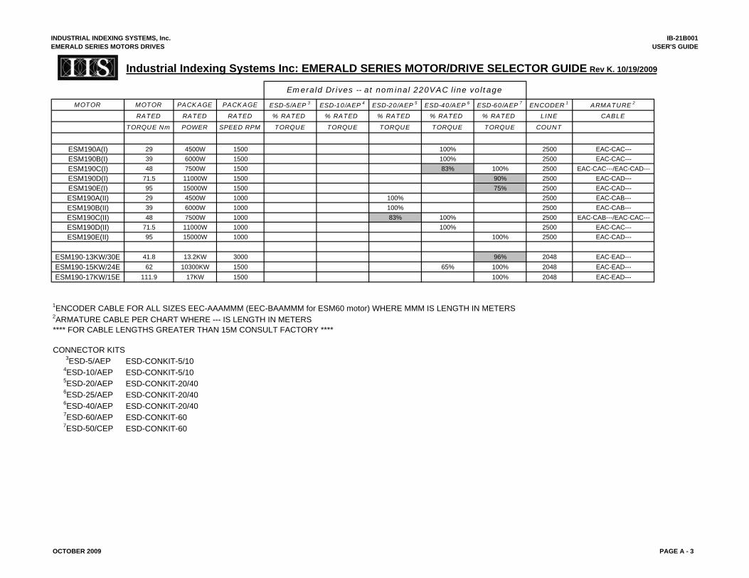
INDUSTRIAL INDEXING SYSTEMS, Inc.EMERALD SERIES MOTORS DRIVES
IB-21B001USER'S GUIDE
Industrial Indexing Systems Inc: EMERALD SERIES MOTOR/DRIVE SELECTOR GUIDE Rev K. 10/19/2009
Emerald Drives -- at nominal 220VAC line voltage
MOTOR MOTOR PACKAGE PACKAGE ESD-5/AEP 3 ESD-10/AEP 4 ESD-20/AEP 5 ESD-40/AEP 6 ESD-60/AEP 7 ENCODER 1 ARMATURE 2
RATED RATED RATED % RATED % RATED % RATED % RATED % RATED LINE CABLE
TORQUE Nm POWER SPEED RPM TORQUE TORQUE TORQUE TORQUE TORQUE COUNT
ESM190A(I) 29 4500W 1500 100% 2500 EAC-CAC---ESM190B(I) 39 6000W 1500 100% 2500 EAC-CAC---ESM190C(I) 48 7500W 1500 83% 100% 2500 EAC-CAC---/EAC-CAD---ESM190D(I) 71.5 11000W 1500 90% 2500 EAC-CAD---ESM190E(I) 95 15000W 1500 75% 2500 EAC-CAD---ESM190A(II) 29 4500W 1000 100% 2500 EAC-CAB---ESM190B(II) 39 6000W 1000 100% 2500 EAC-CAB---ESM190C(II) 48 7500W 1000 83% 100% 2500 EAC-CAB---/EAC-CAC---ESM190D(II) 71.5 11000W 1000 100% 2500 EAC-CAC---ESM190E(II) 95 15000W 1000 100% 2500 EAC-CAD---
ESM190-13KW/30E 41.8 13.2KW 3000 96% 2048 EAC-EAD---ESM190-15KW/24E 62 10300KW 1500 65% 100% 2048 EAC-EAD---ESM190-17KW/15E 111.9 17KW 1500 100% 2048 EAC-EAD---
1ENCODER CABLE FOR ALL SIZES EEC-AAAMMM (EEC-BAAMMM for ESM60 motor) WHERE MMM IS LENGTH IN METERS2ARMATURE CABLE PER CHART WHERE --- IS LENGTH IN METERS**** FOR CABLE LENGTHS GREATER THAN 15M CONSULT FACTORY ****
CONNECTOR KITS3ESD-5/AEP ESD-CONKIT-5/10
4ESD-10/AEP ESD-CONKIT-5/105ESD-20/AEP ESD-CONKIT-20/406ESD-25/AEP ESD-CONKIT-20/406ESD-40/AEP ESD-CONKIT-20/407ESD-60/AEP ESD-CONKIT-607ESD-50/CEP ESD-CONKIT-60
OCTOBER 2009 PAGE A - 3
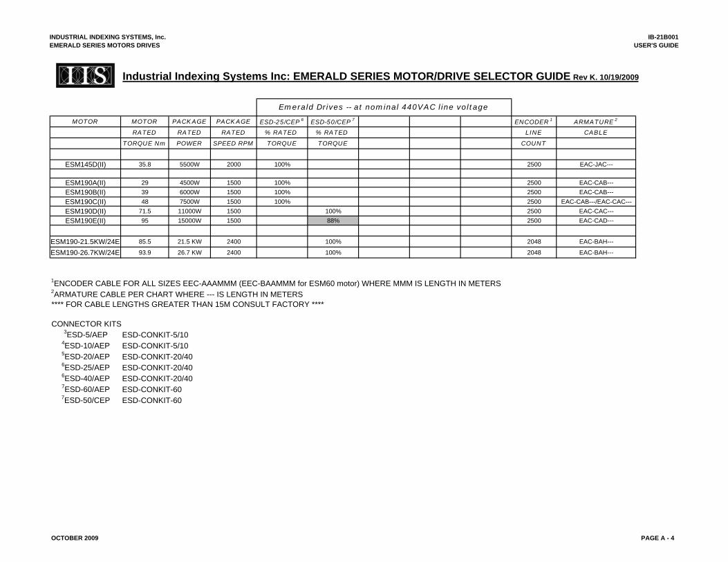
INDUSTRIAL INDEXING SYSTEMS, Inc.EMERALD SERIES MOTORS DRIVES
IB-21B001USER'S GUIDE
Industrial Indexing Systems Inc: EMERALD SERIES MOTOR/DRIVE SELECTOR GUIDE Rev K. 10/19/2009
Emerald Drives -- at nominal 440VAC line voltage
MOTOR MOTOR PACKAGE PACKAGE ESD-25/CEP 6 ESD-50/CEP 7 ENCODER 1 ARMATURE 2
RATED RATED RATED % RATED % RATED LINE CABLE
TORQUE Nm POWER SPEED RPM TORQUE TORQUE COUNT
ESM145D(II) 35.8 5500W 2000 100% 2500 EAC-JAC---
ESM190A(II) 29 4500W 1500 100% 2500 EAC-CAB---ESM190B(II) 39 6000W 1500 100% 2500 EAC-CAB---ESM190C(II) 48 7500W 1500 100% 2500 EAC-CAB---/EAC-CAC---ESM190D(II) 71.5 11000W 1500 100% 2500 EAC-CAC---ESM190E(II) 95 15000W 1500 88% 2500 EAC-CAD---
ESM190-21.5KW/24E 85.5 21.5 KW 2400 100% 2048 EAC-BAH---
ESM190-26.7KW/24E 93.9 26.7 KW 2400 100% 2048 EAC-BAH---
1ENCODER CABLE FOR ALL SIZES EEC-AAAMMM (EEC-BAAMMM for ESM60 motor) WHERE MMM IS LENGTH IN METERS2ARMATURE CABLE PER CHART WHERE --- IS LENGTH IN METERS**** FOR CABLE LENGTHS GREATER THAN 15M CONSULT FACTORY ****
CONNECTOR KITS3ESD-5/AEP ESD-CONKIT-5/10
4ESD-10/AEP ESD-CONKIT-5/105ESD-20/AEP ESD-CONKIT-20/406ESD-25/AEP ESD-CONKIT-20/406ESD-40/AEP ESD-CONKIT-20/407ESD-60/AEP ESD-CONKIT-607ESD-50/CEP ESD-CONKIT-60
OCTOBER 2009 PAGE A - 4
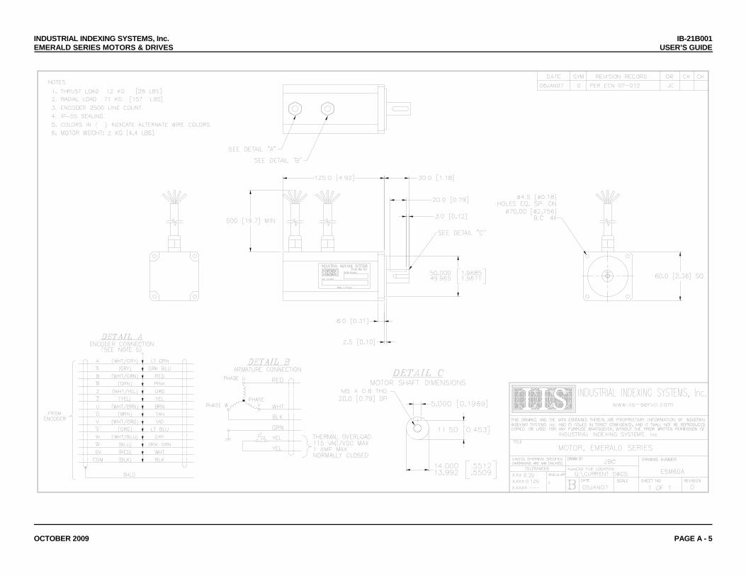
INDUSTRIAL INDEXING SYSTEMS, Inc. IB-21B001 EMERALD SERIES MOTORS & DRIVES USER’S GUIDE
OCTOBER 2009 PAGE A - 5
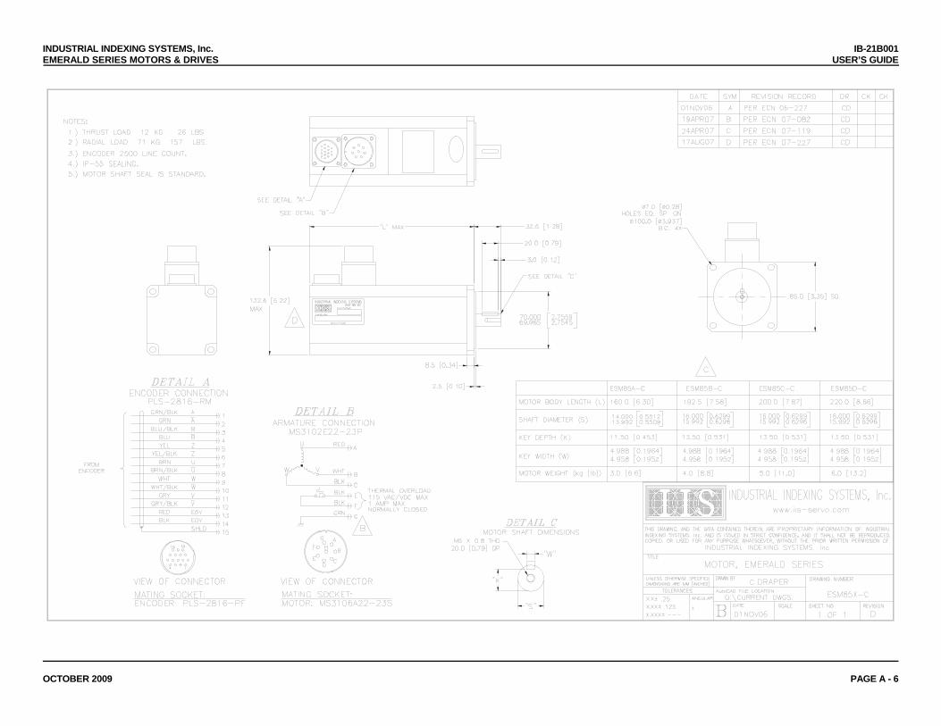
INDUSTRIAL INDEXING SYSTEMS, Inc. IB-21B001 EMERALD SERIES MOTORS & DRIVES USER’S GUIDE
OCTOBER 2009 PAGE A - 6
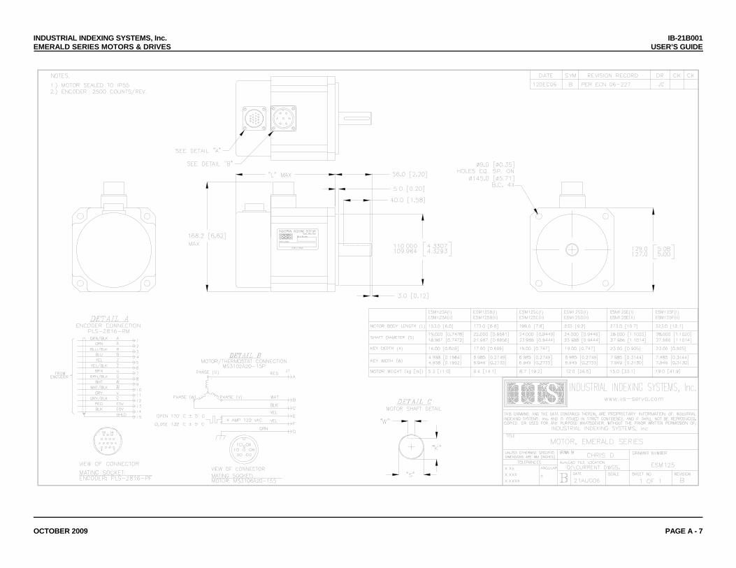
INDUSTRIAL INDEXING SYSTEMS, Inc. IB-21B001 EMERALD SERIES MOTORS & DRIVES USER’S GUIDE
OCTOBER 2009 PAGE A - 7
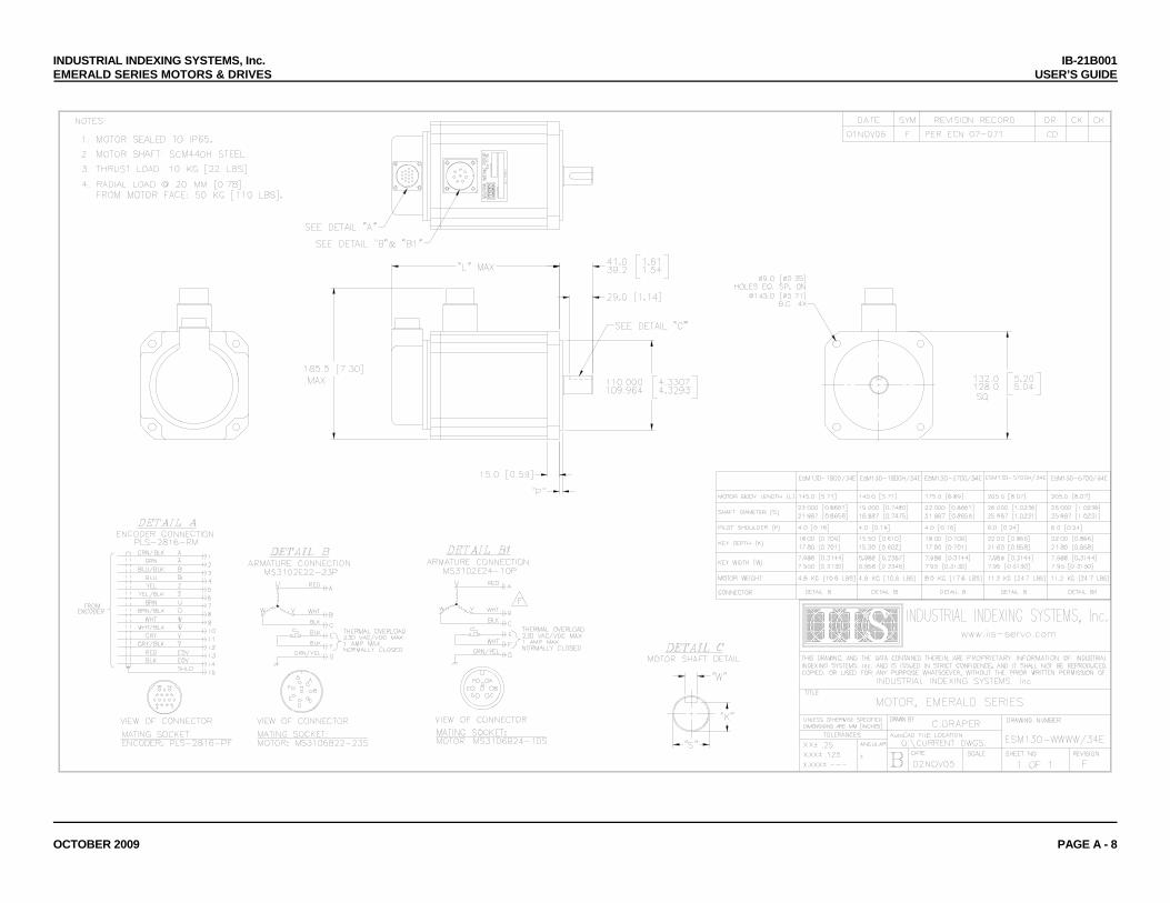
INDUSTRIAL INDEXING SYSTEMS, Inc. IB-21B001 EMERALD SERIES MOTORS & DRIVES USER’S GUIDE
OCTOBER 2009 PAGE A - 8
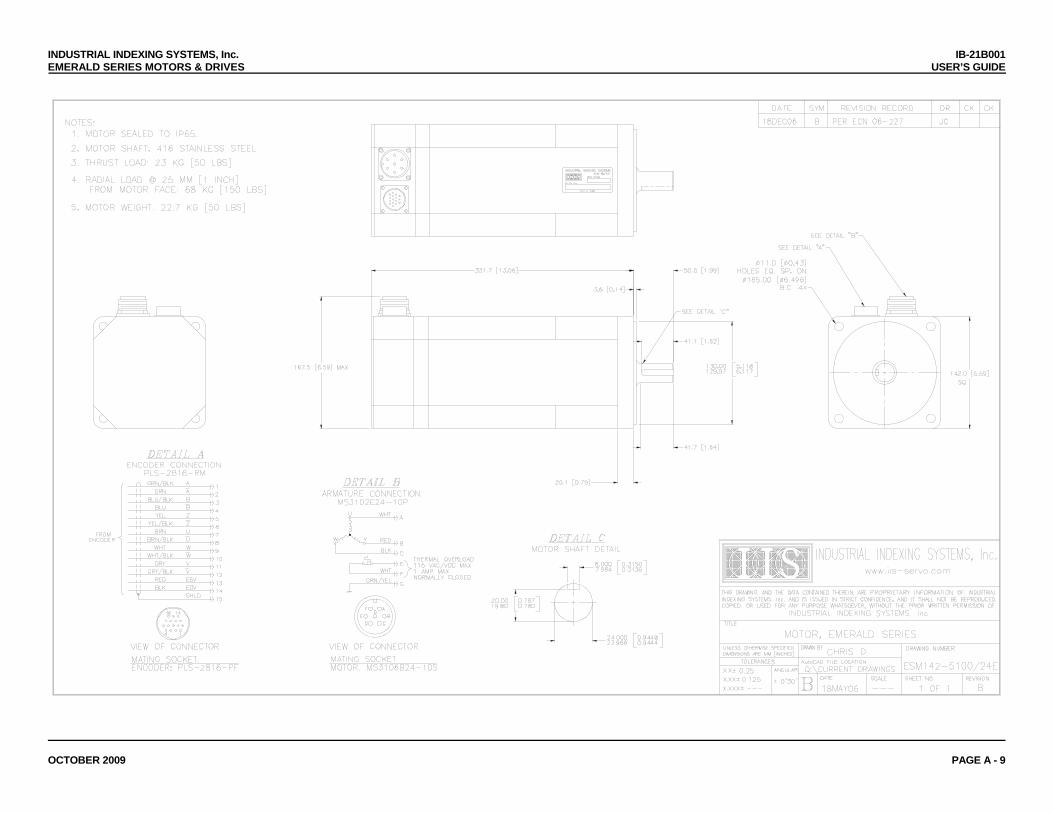
INDUSTRIAL INDEXING SYSTEMS, Inc. IB-21B001 EMERALD SERIES MOTORS & DRIVES USER’S GUIDE
OCTOBER 2009 PAGE A - 9

INDUSTRIAL INDEXING SYSTEMS, Inc. IB-21B001 EMERALD SERIES MOTORS & DRIVES USER’S GUIDE
OCTOBER 2009 PAGE A - 10
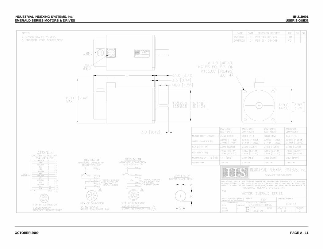
INDUSTRIAL INDEXING SYSTEMS, Inc. IB-21B001 EMERALD SERIES MOTORS & DRIVES USER’S GUIDE
OCTOBER 2009 PAGE A - 11
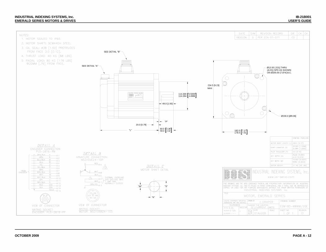
INDUSTRIAL INDEXING SYSTEMS, Inc. IB-21B001 EMERALD SERIES MOTORS & DRIVES USER’S GUIDE
OCTOBER 2009 PAGE A - 12
"K"
"S"
13.50 [.531] THRU
ON Ø200.00 [7.874] B.C.(4) EQ SPD AS SHOWNØ
182.0178.0 [7.17
7.01]
234.5 [9.23]
60.059.0 [2.36
2.32]20.0 [0.79]
"L"
SEE DETAIL "B"
114.300114.264 [4.5000
4.4986]
"P"
49.0 [1.93]
SEE DETAIL "A"
"W"
Ø230.0 [Ø9.06]
MAX
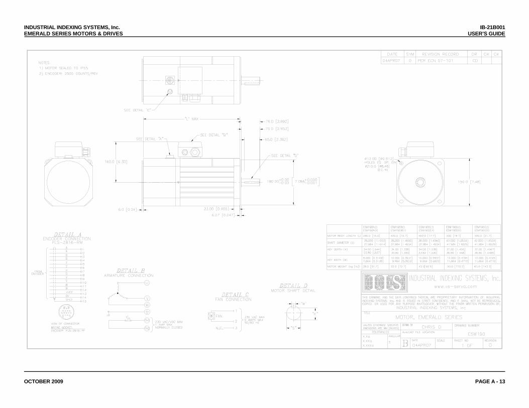
INDUSTRIAL INDEXING SYSTEMS, Inc. IB-21B001 EMERALD SERIES MOTORS & DRIVES USER’S GUIDE
OCTOBER 2009 PAGE A - 13

INDUSTRIAL INDEXING SYSTEMS, Inc. IB-21B001 EMERALD SERIES MOTORS & DRIVES USER’S GUIDE
OCTOBER 2009 PAGE A - 14
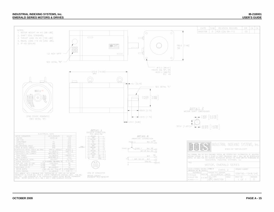
INDUSTRIAL INDEXING SYSTEMS, Inc. IB-21B001 EMERALD SERIES MOTORS & DRIVES USER’S GUIDE
OCTOBER 2009 PAGE A - 15
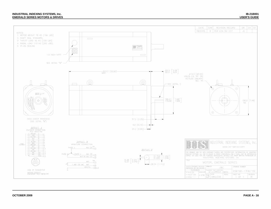
INDUSTRIAL INDEXING SYSTEMS, Inc. IB-21B001 EMERALD SERIES MOTORS & DRIVES USER’S GUIDE
OCTOBER 2009 PAGE A - 16
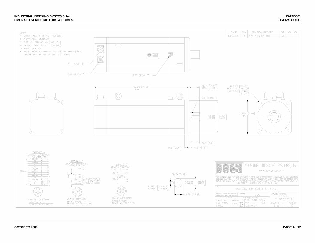
INDUSTRIAL INDEXING SYSTEMS, Inc. IB-21B001 EMERALD SERIES MOTORS & DRIVES USER’S GUIDE
OCTOBER 2009 PAGE A - 17
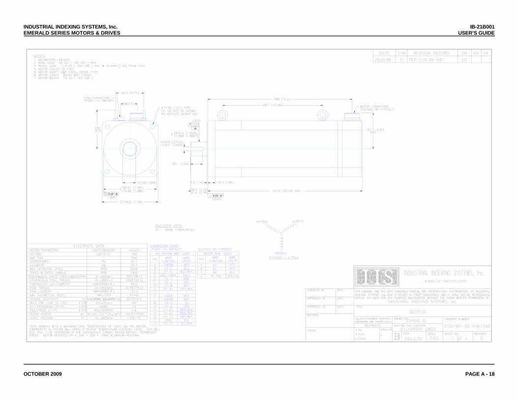
INDUSTRIAL INDEXING SYSTEMS, Inc. IB-21B001 EMERALD SERIES MOTORS & DRIVES USER’S GUIDE
OCTOBER 2009 PAGE A - 18
-A-
A0.10A0.10
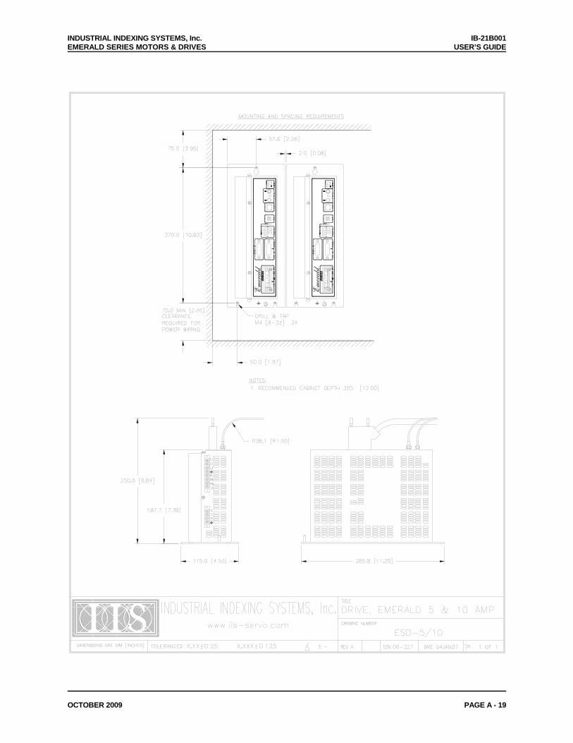
INDUSTRIAL INDEXING SYSTEMS, Inc. IB-21B001 EMERALD SERIES MOTORS & DRIVES USER’S GUIDE
OCTOBER 2009 PAGE A - 19
Emerald
Emerald
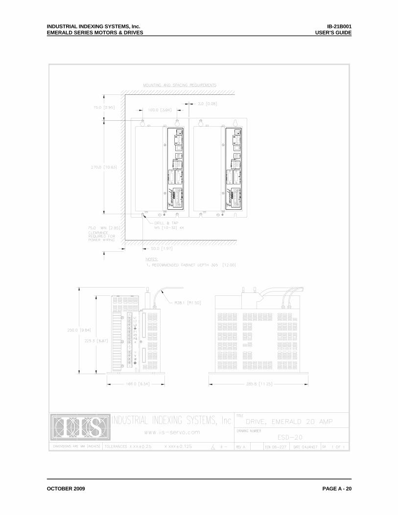
INDUSTRIAL INDEXING SYSTEMS, Inc. IB-21B001 EMERALD SERIES MOTORS & DRIVES USER’S GUIDE
OCTOBER 2009 PAGE A - 20
Emerald
Emerald
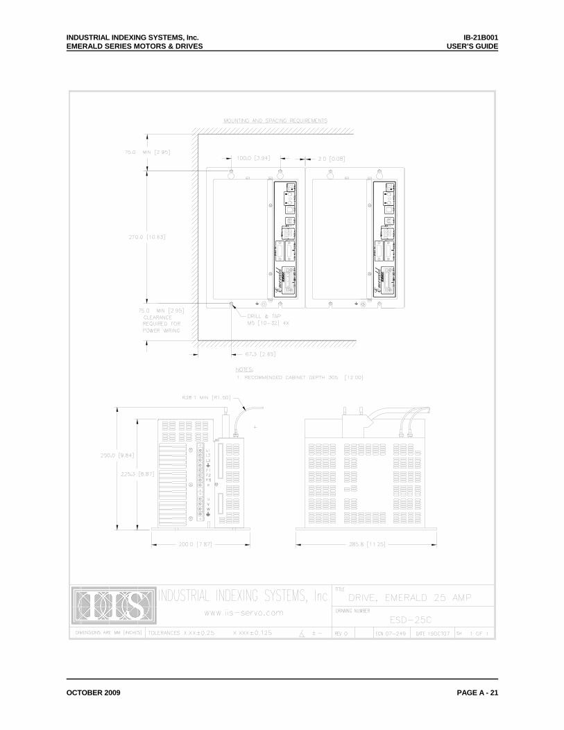
INDUSTRIAL INDEXING SYSTEMS, Inc. IB-21B001 EMERALD SERIES MOTORS & DRIVES USER’S GUIDE
OCTOBER 2009 PAGE A - 21
Emerald
Emerald

INDUSTRIAL INDEXING SYSTEMS, Inc. IB-21B001 EMERALD SERIES MOTORS & DRIVES USER’S GUIDE
OCTOBER 2009 PAGE A - 22
Emerald
Emerald

INDUSTRIAL INDEXING SYSTEMS, Inc. IB-21B001 EMERALD SERIES MOTORS & DRIVES USER’S GUIDE
OCTOBER 2009 PAGE A - 23
CAUTION! High earth leakagecurrent device. See user manual.
CAUTION! High earth leakagecurrent device. See user manual.
DANGER! Hazardous voltage present 5 minutesafter power is removed. See user manual.
DANGER! Hazardous voltage present 5 minutesafter power is removed. See user manual.
24V DC Power Supply10A max.
Emerald
24V DC Power Supply10A max.
Emerald
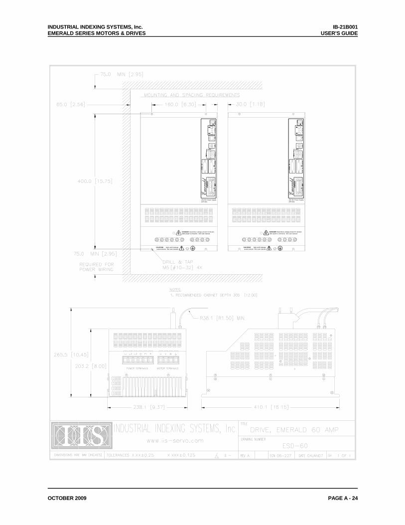
INDUSTRIAL INDEXING SYSTEMS, Inc. IB-21B001 EMERALD SERIES MOTORS & DRIVES USER’S GUIDE
OCTOBER 2009 PAGE A - 24
CAUTION! High earth leakagecurrent device. See user manual.
CAUTION! High earth leakagecurrent device. See user manual.
DANGER! Hazardous voltage present 5 minutesafter power is removed. See user manual.
DANGER! Hazardous voltage present 5 minutesafter power is removed. See user manual.
24V DC Power Supply10A max.
Emerald
24V DC Power Supply10A max.
Emerald
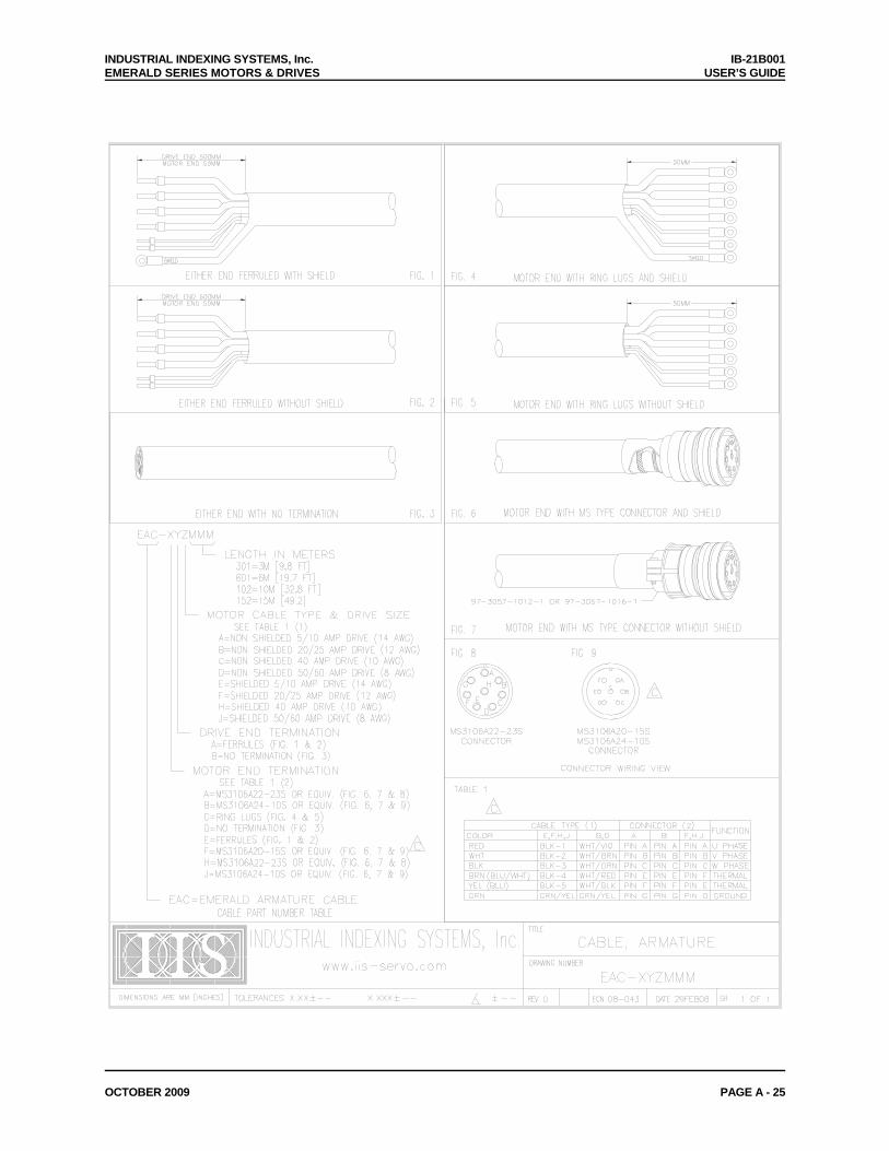
INDUSTRIAL INDEXING SYSTEMS, Inc. IB-21B001 EMERALD SERIES MOTORS & DRIVES USER’S GUIDE
OCTOBER 2009 PAGE A - 25
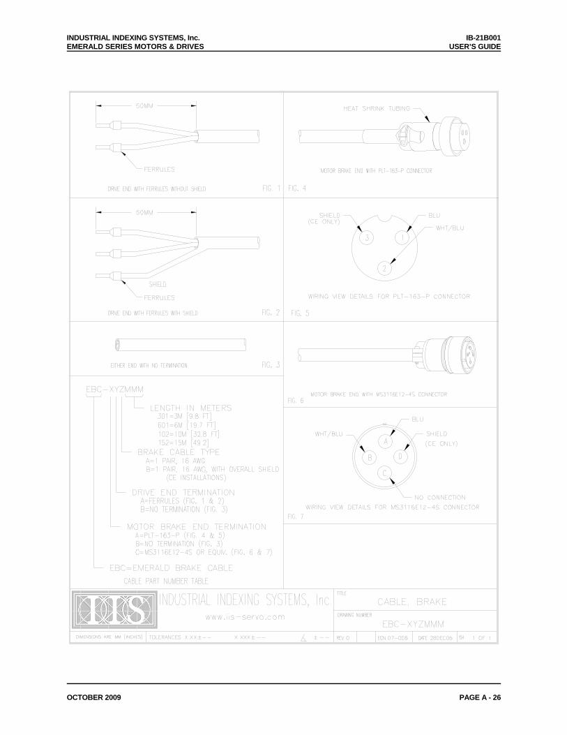
INDUSTRIAL INDEXING SYSTEMS, Inc. IB-21B001 EMERALD SERIES MOTORS & DRIVES USER’S GUIDE
OCTOBER 2009 PAGE A - 26
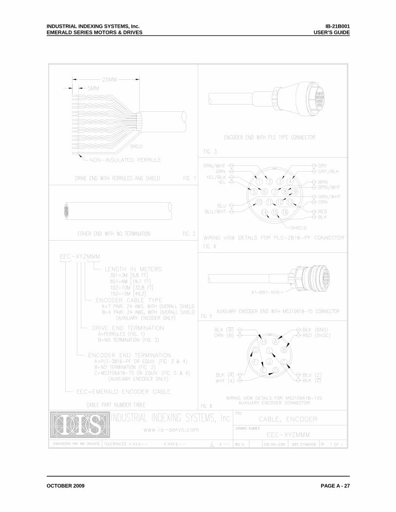
INDUSTRIAL INDEXING SYSTEMS, Inc. IB-21B001 EMERALD SERIES MOTORS & DRIVES USER’S GUIDE
OCTOBER 2009 PAGE A - 27
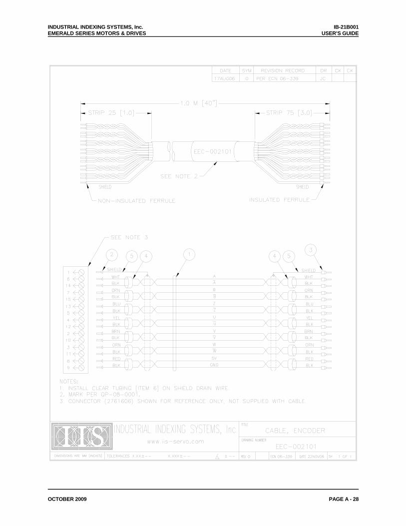
INDUSTRIAL INDEXING SYSTEMS, Inc. IB-21B001 EMERALD SERIES MOTORS & DRIVES USER’S GUIDE
OCTOBER 2009 PAGE A - 28
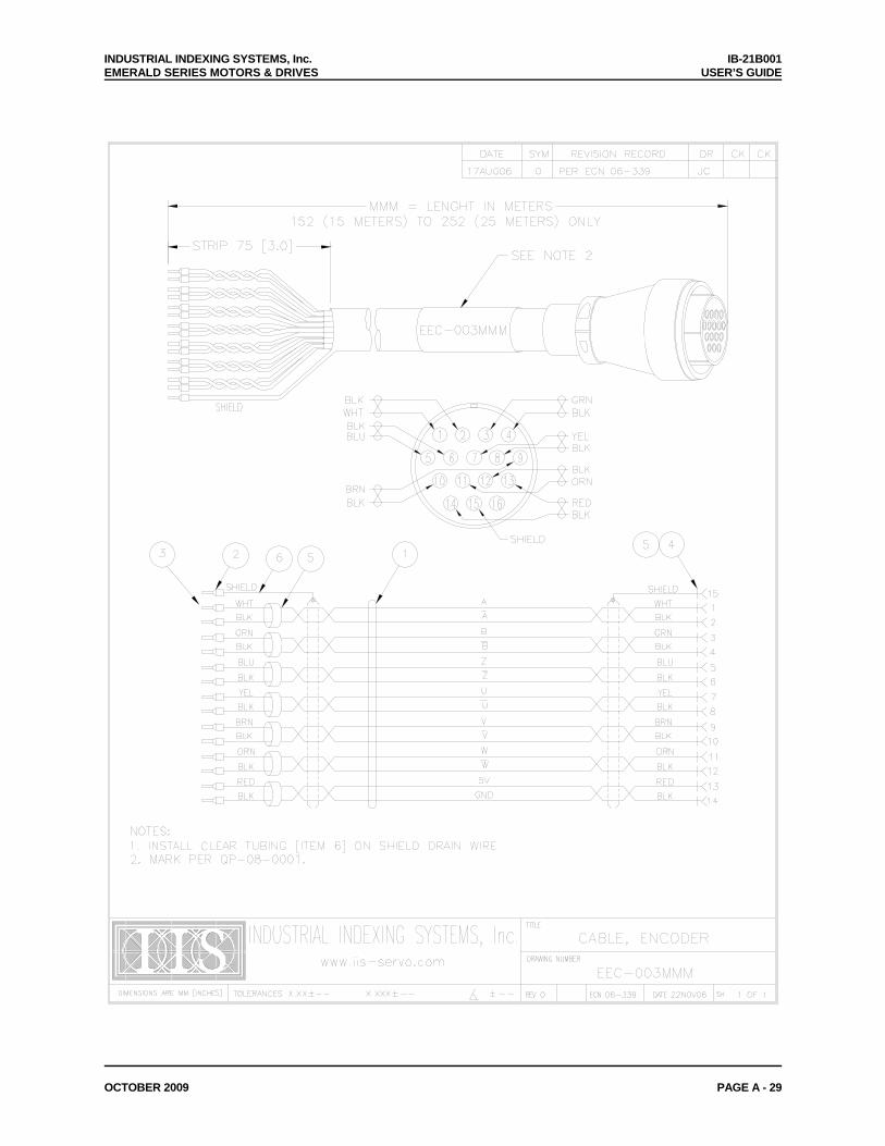
INDUSTRIAL INDEXING SYSTEMS, Inc. IB-21B001 EMERALD SERIES MOTORS & DRIVES USER’S GUIDE
OCTOBER 2009 PAGE A - 29

INDUSTRIAL INDEXING SYSTEMS, Inc. IB-21B001 EMERALD SERIES MOTORS & DRIVES USER’S GUIDE
OCTOBER 2009 PAGE A - 30
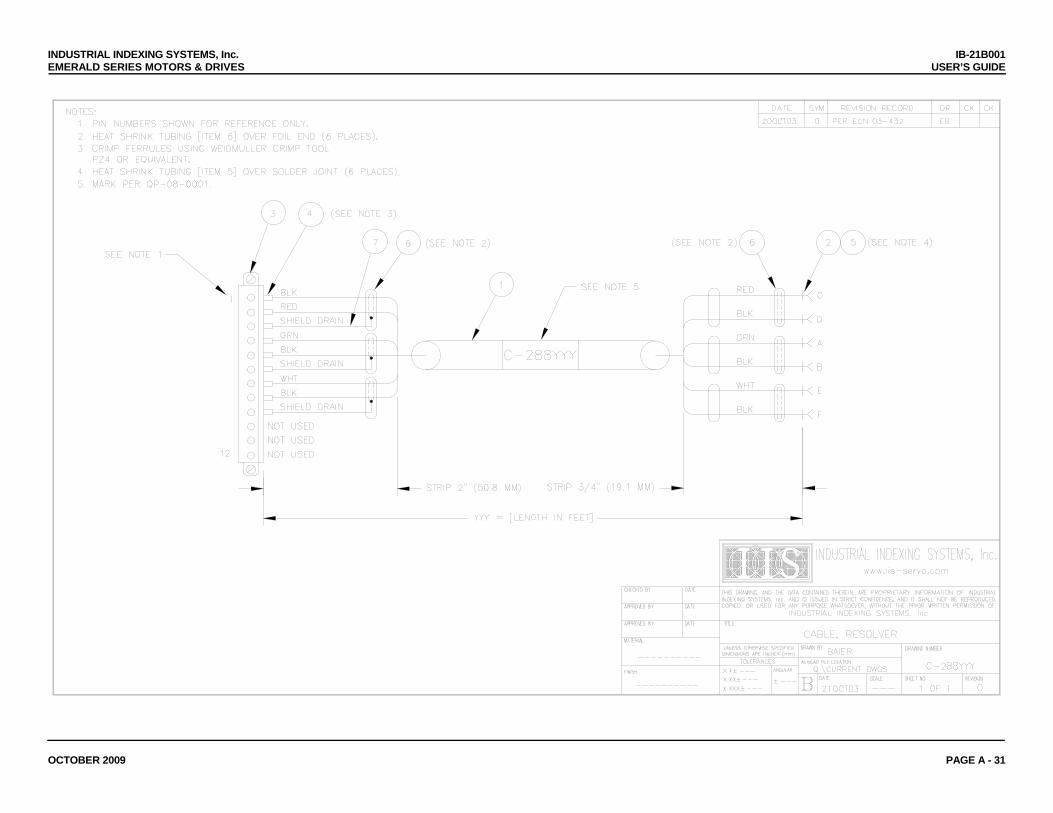
INDUSTRIAL INDEXING SYSTEMS, Inc. IB-21B001 EMERALD SERIES MOTORS & DRIVES USER’S GUIDE
OCTOBER 2009 PAGE A - 31
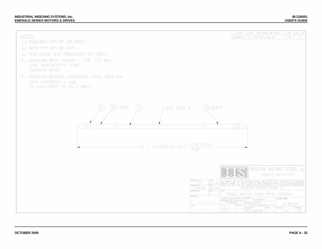
INDUSTRIAL INDEXING SYSTEMS, Inc. IB-21B001 EMERALD SERIES MOTORS & DRIVES USER’S GUIDE
OCTOBER 2009 PAGE A - 32

INDUSTRIAL INDEXING SYSTEMS, Inc. IB-21B001 EMERALD SERIES MOTORS & DRIVES USER’S GUIDE
OCTOBER 2009 PAGE A - 33
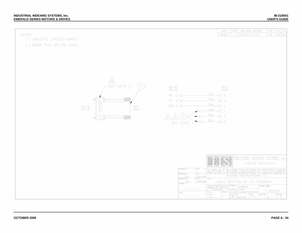
INDUSTRIAL INDEXING SYSTEMS, Inc. IB-21B001 EMERALD SERIES MOTORS & DRIVES USER’S GUIDE
OCTOBER 2009 PAGE A - 34
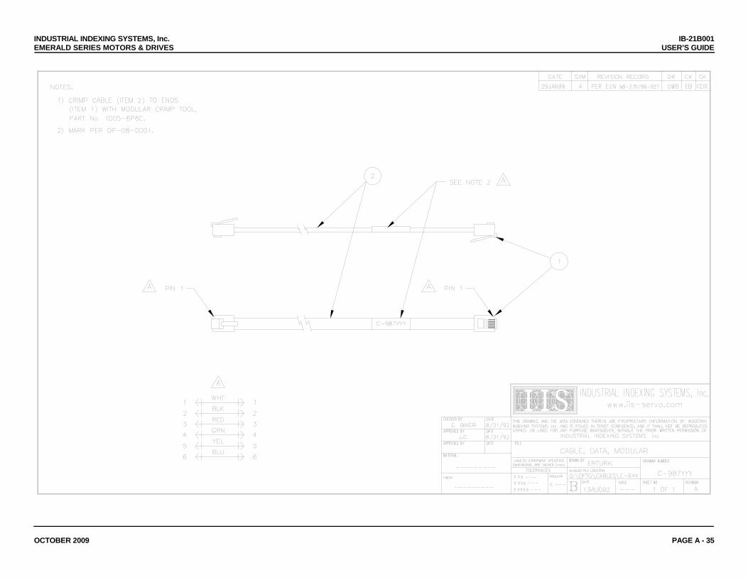
INDUSTRIAL INDEXING SYSTEMS, Inc. IB-21B001 EMERALD SERIES MOTORS & DRIVES USER’S GUIDE
OCTOBER 2009 PAGE A - 35
INDUSTRIAL INDEXING SYSTEMS, Inc. IB-21B001 EMERALD SERIES MOTORS & DRIVES USER’S GUIDE
SEPTEMBER 2008 PAGE B - 1
APPENDIX B - ESD-I/O16 & ESD-IO16-DC I/O EXPANDER
B.1 OVERVIEW
This manual is organized so that information is easy to find and easy to use. It begins by giving a general description of the ESD-I/O16 and the ESD-IO16-DC. Next, a comprehensive hardware specification is provided followed by connector wiring diagrams, and finally the status indicators. B.2 DESCRIPTION The ESD-I/O16 and the ESD-IO16-DC are I/O for the Industrial Indexing Systems E-Series and is a DIN rail mounted assembly. Power supplied to the ESD-I/O16 devices is 24V DC. See Section 3 on specifications. The ESD-I/O16 may be configured to have 16 I/O in any configuration with multiple voltage ranges using the I/O modules described in Section B.3.4. The ESD-IO16-DC may be configured to have 16 I/O in any configuration but is limited to 24V DC voltage range. Each E-Series device can support up to 2 ESD-I/O16’s or 2 ESD-IO16-DC’s or 1 ESD-I/O16 and 1 ESD-IO16-DC. The ESD-I/O16 and the ESD-IO16-DC must be configured through the EDE (Emerald Development Environment) to function as needed. The ESD-I/O16 and the ESD-IO16-DC are connected to an E-Series device using an IIS EXC-XYZMMM cable (See Appendix A). Two ESD-I/O16 or ESD-IO16-DC can be connected together using two EXC-XYZMMM cables (See Appendix A). The ESD-I/O16 and the ESD-IO16-DC read the switch SW1 to determine its’ address. If the address is valid, it starts trying to establish a connection with the E-Series device. When the E-Series device receives the request for a connection from the ESD-I/O16 or the ESD-IO16-DC it responds by sending over the I/O configuration. After the ESD-I/O16 or the ESD-IO16-DC receives the configuration the status returned to the E-Series device is changed indicating that the ESD-I/O16 and the ESD-IO16-DC is configured correctly. The E-Series device then begins requesting data and setting the output state every 1 millisecond. If something causes the update rate to be greater than 1 millisecond, then the ESD-I/O16 or the ESD-IO16-DC will return to the not configured state. The E-Series device will fault when this occurs. B.3 SPECIFICATIONS
B.3.1 POWER REQUIREMENT Control Voltage 24V DC +/- 10% .25 Amps
B.3.2 ENVIRONMENT Storage Temperature
-10 to 70°C/14-158°F
Operating Temperature
0 to 55°C/32-131°F
Humidity 35 to 90% Relative Humidity, non-condensing Shock and Vibration
1 G or less
Operating Conditions
Free of dust, liquids, metallic particles and corrosive gases. Use in a pollution degree 2 environment.
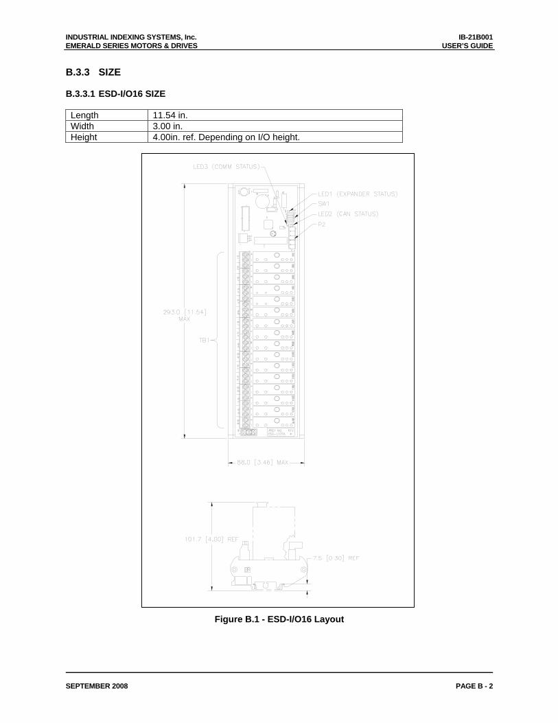
INDUSTRIAL INDEXING SYSTEMS, Inc. IB-21B001 EMERALD SERIES MOTORS & DRIVES USER’S GUIDE
SEPTEMBER 2008 PAGE B - 2
B.3.3 SIZE B.3.3.1 ESD-I/O16 SIZE Length 11.54 in. Width 3.00 in. Height 4.00in. ref. Depending on I/O height.
Figure B.1 - ESD-I/O16 Layout
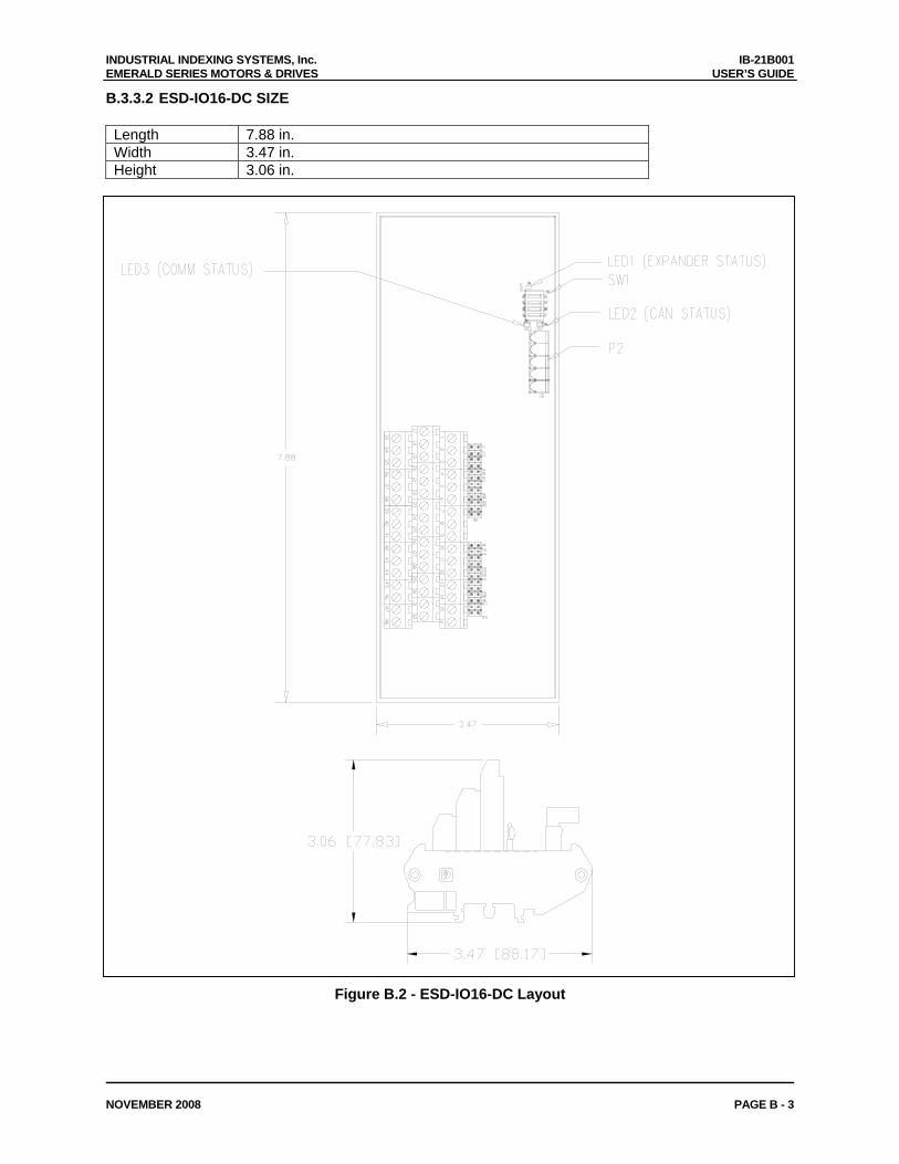
INDUSTRIAL INDEXING SYSTEMS, Inc. IB-21B001 EMERALD SERIES MOTORS & DRIVES USER’S GUIDE
NOVEMBER 2008 PAGE B - 3
B.3.3.2 ESD-IO16-DC SIZE Length 7.88 in. Width 3.47 in. Height 3.06 in.
Figure B.2 - ESD-IO16-DC Layout
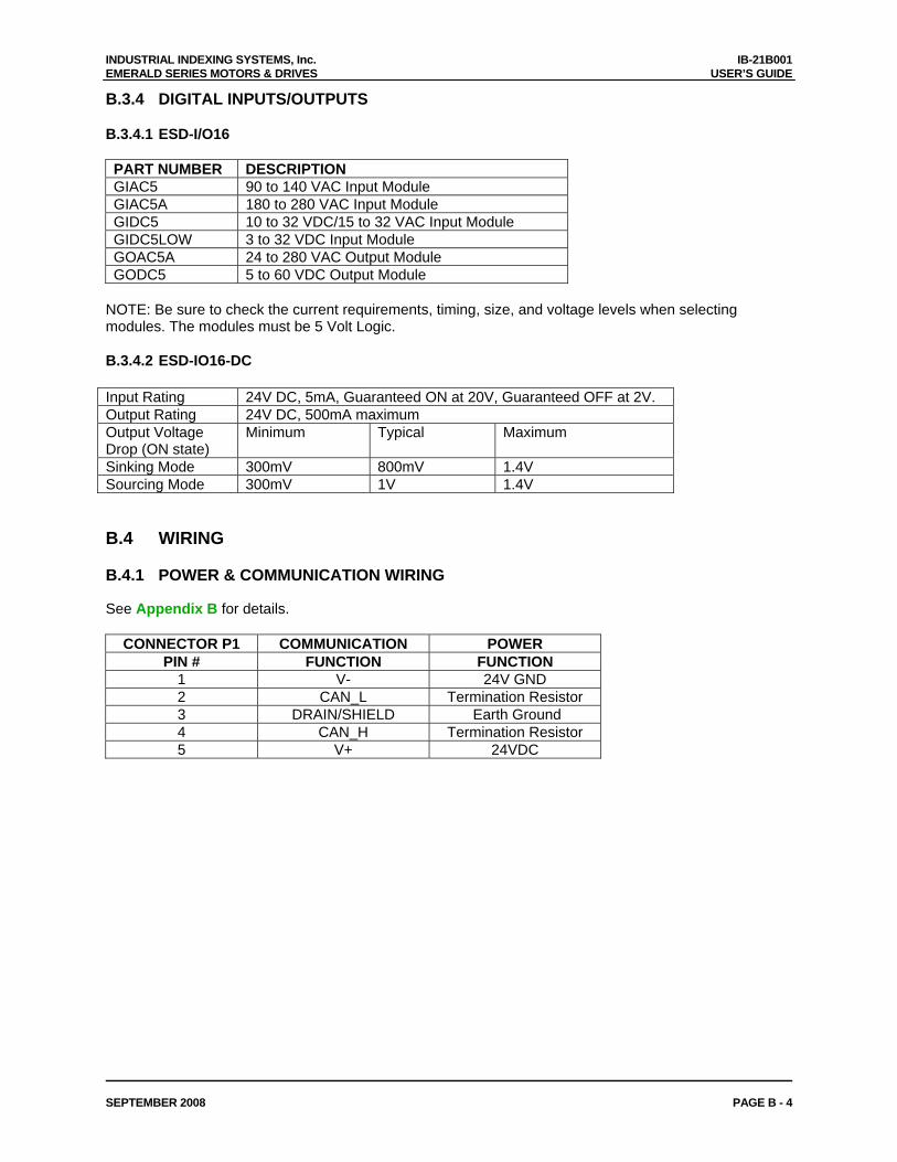
INDUSTRIAL INDEXING SYSTEMS, Inc. IB-21B001 EMERALD SERIES MOTORS & DRIVES USER’S GUIDE
SEPTEMBER 2008 PAGE B - 4
B.3.4 DIGITAL INPUTS/OUTPUTS B.3.4.1 ESD-I/O16 PART NUMBER DESCRIPTION GIAC5 90 to 140 VAC Input Module GIAC5A 180 to 280 VAC Input Module GIDC5 10 to 32 VDC/15 to 32 VAC Input Module GIDC5LOW 3 to 32 VDC Input Module GOAC5A 24 to 280 VAC Output Module GODC5 5 to 60 VDC Output Module
NOTE: Be sure to check the current requirements, timing, size, and voltage levels when selecting modules. The modules must be 5 Volt Logic. B.3.4.2 ESD-IO16-DC Input Rating 24V DC, 5mA, Guaranteed ON at 20V, Guaranteed OFF at 2V. Output Rating 24V DC, 500mA maximum Output Voltage Drop (ON state)
Minimum Typical Maximum
Sinking Mode 300mV 800mV 1.4V Sourcing Mode 300mV 1V 1.4V B.4 WIRING
B.4.1 POWER & COMMUNICATION WIRING See Appendix B for details.
CONNECTOR P1 COMMUNICATION POWER PIN # FUNCTION FUNCTION
1 V- 24V GND 2 CAN_L Termination Resistor 3 DRAIN/SHIELD Earth Ground 4 CAN_H Termination Resistor 5 V+ 24VDC
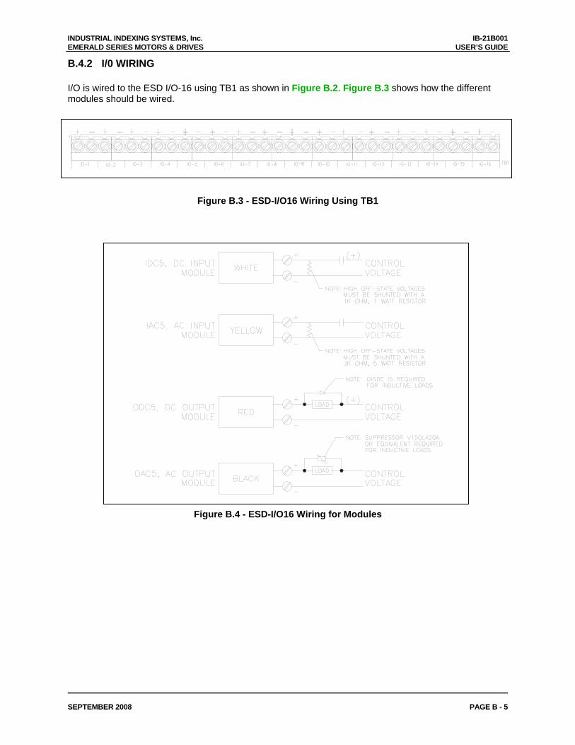
INDUSTRIAL INDEXING SYSTEMS, Inc. IB-21B001 EMERALD SERIES MOTORS & DRIVES USER’S GUIDE
SEPTEMBER 2008 PAGE B - 5
B.4.2 I/0 WIRING I/O is wired to the ESD I/O-16 using TB1 as shown in Figure B.2. Figure B.3 shows how the different modules should be wired.
Figure B.3 - ESD-I/O16 Wiring Using TB1
Figure B.4 - ESD-I/O16 Wiring for Modules
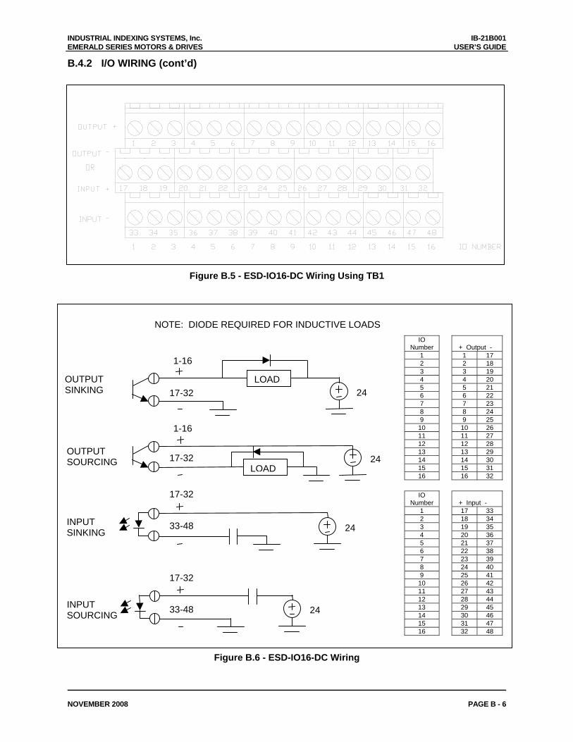
INDUSTRIAL INDEXING SYSTEMS, Inc. IB-21B001 EMERALD SERIES MOTORS & DRIVES USER’S GUIDE
NOVEMBER 2008 PAGE B - 6
B.4.2 I/O WIRING (cont’d)
Figure B.5 - ESD-IO16-DC Wiring Using TB1
NOTE: DIODE REQUIRED FOR INDUCTIVE LOADS IO
Number
+ Output - 1 1 17 2 2 18 3 3 19 4 4 20 5 5 21 6 6 22 7 7 23 8 8 24 9 9 25
10 10 26 11 11 27 12 12 28 13 13 29 14 14 30 15 15 31 16 16 32
IO Number
+ Input -
1 17 33 2 18 34 3 19 35 4 20 36 5 21 37 6 22 38 7 23 39 8 24 40 9 25 41
10 26 42 11 27 43 12 28 44 13 29 45 14 30 46 15 31 47 16 32 48
OUTPUT SINKING
OUTPUT SOURCING
INPUT SINKING
INPUT SOURCING
LOAD
1-16
LOAD
2433-48
17-32
2433-48
17-32
2417-32
1-16
17-32 24
Figure B.6 - ESD-IO16-DC Wiring
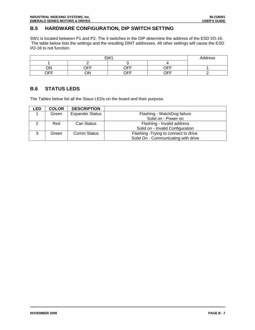
INDUSTRIAL INDEXING SYSTEMS, Inc. IB-21B001 EMERALD SERIES MOTORS & DRIVES USER’S GUIDE
NOVEMBER 2008 PAGE B - 7
B.5 HARDWARE CONFIGURATION, DIP SWITCH SETTING SW1 is located between P1 and P2. The 4 switches in the DIP determine the address of the ESD I/O-16. The table below lists the settings and the resulting DINT addresses. All other settings will cause the ESD I/O-16 to not function.
SW1
1 2 3 4 Address
ON OFF OFF OFF 1 OFF ON OFF OFF 2
B.6 STATUS LEDS
The Tables below list all the Staus LEDs on the board and their purpose.
LED COLOR DESCRIPTION 1 Green Expander Status Flashing - WatchDog failure
Solid on - Power on 2 Red Can Status Flashing - Invalid address
Solid on - Invalid Configuration 3 Green Comm Status Flashing -Trying to connect to drive.
Solid On - Communicating with drive
INDUSTRIAL INDEXING SYSTEMS, Inc. IB-21B001 EMERALD SERIES MOTORS & DRIVES USER’S GUIDE
APRIL 2008 PAGE C - 1
APPENDIX C - EMC INSTALLATION GUIDELINES FOR EMERALD SERIES MOTORS AND DRIVERS
C.1 INTRODUCTION TO EMC GUIDELINES This chapter provides guidance and requirements when installing IIS Emerald Series motors and drivers into industrial control machinery required to be CE marked. These guidelines are intended to provide the machine builder with the necessary EMC information, including parts and wiring techniques to comply with the European Community Standards for industrial control equipment. The final conformance to the standards for the overall machine remains the sole responsibility of the machine builder. C.2 EMC REQUIREMENTS In 1996, the European Community enacted standards concerning conducted and radiated emissions and immunity to various types of interference for industrial control equipment. The EMC Directive 89/336/EEC and harmonized standards define specific EMC levels and test procedures to gain conformance. Emission Standards provide maximum levels of noise permitted to be generated by the equipment. Immunity Standards subject the equipment to various types of disturbances and verifies that the equipment continues to perform in a safe manner. The IIS Emerald Series motors and drivers have been tested and have been shown to comply with the following standards when installed per the guidelines in this section. EMISSIONS STANDARDS: EN55011 Class A Power line conducted noise EN55011 Class A Radiated noise IMMUNITY STANDARDS: EN61000-4-2 Static discharge ENV50140 & ENV50204 Electromagnetic irradiation EN61000-4-4 Burst noise injected into power and signal wiring EN61000-4-5 Lightning surge into power line ENV50141 RF frequency injection into power and signal wiring EN61000-4-8 Power frequency magnetic field EN61000-4-11 Power line fluctuation and drop out
INDUSTRIAL INDEXING SYSTEMS, Inc. IB-21B001 EMERALD SERIES MOTORS & DRIVES USER’S GUIDE
APRIL 2008 Page C - 2
C.3 CONTROL ENCLOSURE The Emerald Series drivers must be installed in a suitable control enclosure that provides a good quality ground system and tight construction. The cabinets can be of welded construction, metal to metal conductive joints or have overlapping EMC gasketed joints. All joints and removable panels must have metal-to-metal ground contact. All hinged panels or doors must have a bonded ground wire from the hinged panel to the main body of the enclosure. C.4 ENCLOSURE MOUNTING PANEL It is highly recommended that a galvanized panel be used. Galvanized panels provide a continuous conductive surface that provides a low impedance ground plane for mounting the servo components. The mounting panel must be grounded to the control enclosure with metal to metal joints, bolted together with external tooth lock washers or have multiple short ground jumper wires between the panel and the enclosure. Painted panels can be used if the mounting area for the servo components and all grounding points have been masked off or have the paint removed. All servo components that require grounding must use fasteners with external tooth lock washers.
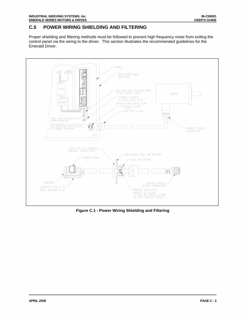
INDUSTRIAL INDEXING SYSTEMS, Inc. IB-21B001 EMERALD SERIES MOTORS & DRIVES USER’S GUIDE
APRIL 2008 PAGE C - 3
C.5 POWER WIRING SHIELDING AND FILTERING Proper shielding and filtering methods must be followed to prevent high frequency noise from exiting the control panel via the wiring to the driver. This section illustrates the recommended guidelines for the Emerald Driver.
OK
Emerald
−+
−+
MO
TO
R E
NC
I/O
BU
S
24V
DC
AU
X E
NC
PR
OB
ES
AN
ALO
GU
SB
STAT
SE
RC
OS
CO
M
RX
TU
SA
ST
TX
Figure C.1 - Power Wiring Shielding and Filtering
INDUSTRIAL INDEXING SYSTEMS, Inc. IB-21B001 EMERALD SERIES MOTORS & DRIVES USER’S GUIDE
APRIL 2008 Page C - 4
C.5.1 POWER LINE FILTER A filter must be installed between the Emerald Series Driver and the incoming power line to prevent conducted noise for getting onto the power line. It is recommended that a separate filter be used for each driver but it is possible to use a single larger filter to supply multiple drivers if the wiring between the filter and drivers is kept as short as possible. See Figure C.1. The following power line filters are recommended for use with the Emerald Series motors and drivers:
Total Motor Capacity Phase SCHAFFNER ELECTRONIC AG 500W max. 1 FN 2070-3 500W -> 1000W 1 FN 2070-6 1000W ->2200W 3 FN 258-16 2200W -> 3700W 3 FN 258-30 3700W -> 6500W 3 FN 258-42 6500W -> 11000W 3 FN 258-55
C.5.2 DRIVER OUTPUT (MOTOR ARMATURE) FILTER The Emerald Series Driver uses pulse width modulation (PWM) control of the motor windings. The PWM switching of the motor output generates transient voltages that must be suppressed before exiting the control enclosure. A simple ferrite core can be used as shown in Figure C.1. The following ferrite core filters are recommended for use with the Emerald Series motors and drivers:
Drive Size Manufacturer Part Number ESD-5/AEP -> ESD-60/AEP Fair-Rite 0431176451
C.5.3 SHIELDED MOTOR CABLE The motor armature cable between the driver and motor must be shielded and grounded at both the driver and motor end. The motor armature cable length between the control enclosure and motor must be less than 50 meters or additional shield is necessary. The shielded motor armature cables specified in Appendix B wire are recommended. Either SKINTOP or saddle clamp method of grounding must be used as shown in Figure C.1.
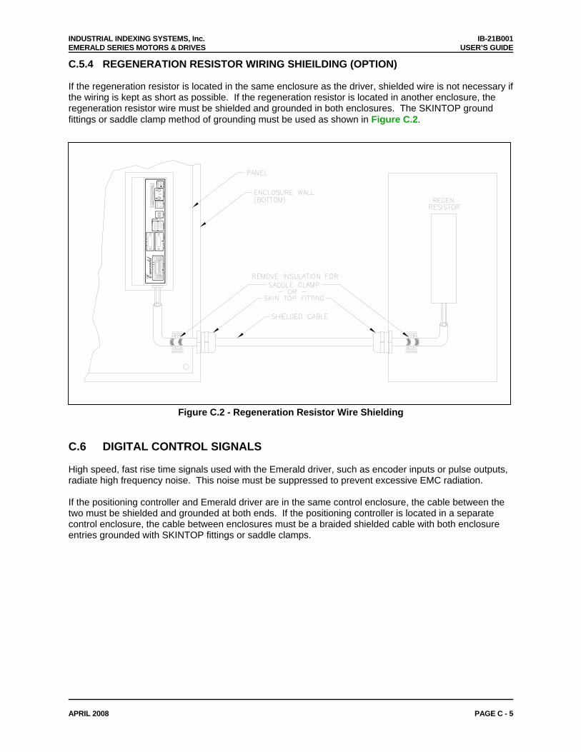
INDUSTRIAL INDEXING SYSTEMS, Inc. IB-21B001 EMERALD SERIES MOTORS & DRIVES USER’S GUIDE
APRIL 2008 PAGE C - 5
C.5.4 REGENERATION RESISTOR WIRING SHIEILDING (OPTION) If the regeneration resistor is located in the same enclosure as the driver, shielded wire is not necessary if the wiring is kept as short as possible. If the regeneration resistor is located in another enclosure, the regeneration resistor wire must be shielded and grounded in both enclosures. The SKINTOP ground fittings or saddle clamp method of grounding must be used as shown in Figure C.2.
OK
Emerald
−+
−+
MO
TO
R E
NC
I/O B
US
24V
DC
AU
X E
NC
PR
OB
ES
AN
ALO
GU
SB
STAT
SE
RC
OS
CO
M
RX
TU
SA
ST
TX
Figure C.2 - Regeneration Resistor Wire Shielding C.6 DIGITAL CONTROL SIGNALS High speed, fast rise time signals used with the Emerald driver, such as encoder inputs or pulse outputs, radiate high frequency noise. This noise must be suppressed to prevent excessive EMC radiation. If the positioning controller and Emerald driver are in the same control enclosure, the cable between the two must be shielded and grounded at both ends. If the positioning controller is located in a separate control enclosure, the cable between enclosures must be a braided shielded cable with both enclosure entries grounded with SKINTOP fittings or saddle clamps.

IB-21B001
INDUSTRIAL INDEXING SYSTEMS INC. 626 FISHERS RUN VICTOR, NEW YORK 14564 (585) 924-9181 FAX: (585) 924-2169
PRINTED IN USA © 2008