Embed Size (px)
Citation preview

TRANSTECH 1000 OPERATOR MANUAL - 100-1101
Rev. A, 2006
MOTORVAC TECHNOLOGIES INC.
TRANSTECH-1000 Transmission Service System
OPERATOR MANUAL
UNIT MODEL NUMBER 500-1101
Table of Contents
Introduction ...........................................................................................................................................3 Overview ................................................................................................................................................4 System Features and Functions...................................................................................................... 1-1
Control Panel Features and Functions......................................................................................... 1-2 Theory of Operation ………………………………………………………………………………… .... 1-4
Safety Information............................................................................................................................. 2-1 Before You Begin .............................................................................................................................. 3-1
First Time Operation..................................................................................................................... 3-1 Transmission Service Procedure .................................................................................................... 4-1 Frequently Asked Questions ........................................................................................................... 5-1 Troubleshooting and Additional Help............................................................................................. 6-1 Appendix A - Maintenance ...............................................................................................................A-1
Maintenance Procedures..............................................................................................................A-1 Cleaning the Unit’s Filter Screen ………………………………………………………………………A-1 Maintenance Record ....................................................................................................................A-3
Appendix B - System Accessories..................................................................................................B-1 Adapter Kits ………………………………………………………………………………………..……..B-1
Appendix C - Parts ............................................................................................................................C-1 External Parts ..............................................................................................................................C-1 Ordering Parts……………………………………………………………………………………………C-1

Introduction
Congratulations on your selection of the TRANSTECH-1000 Transmission Service System. By choosing this product, you are acquiring the most technologically advanced method available for automatic transmission service fluid exchange. The TRANSTECH-1000 System is a self-contained system; designed to service any automatic transmission thru it’s’ dipstick tube. Once the unit is connected, it can be used to drain the fluid from the vehicle’s transmission for filter replacement and/or to completely exchange the transmission fluid with new fluid, without removing the vehicle’s transmission fluid pan. It is recommended that a vehicle’s transmission lubrication system be serviced every 15,000 miles (Or according to the vehicle owner’s manual) to obtain the highest lubricant protection, to reduce friction from internal transmission components, and thus increase the efficiency and life span of the transmission to its’ maximum. Please study this Operators Manual to become thoroughly familiar with the TRANSTECH-1000 Transmission Service System.
IMPORTANT
The TRANSTECH-1000 Transmission Service System is designed to work EXCLUSIVELY
with Automatic Transmission Fluid.
Use of any chemical during this process may cause operational failure of the TRANSTECH-1000 System and voids the manufacturer’s warranty.
See warranty card for details.
Overview This manual contains all the information you need to use the TRANSTECH-1000 System. Please make sure all technicians using the unit read this manual and have it within easy reach whenever the unit is being used. The following is a quick reference to the information in this manual: System Features and Functions
This chapter describes the TRANSTECH-1000 Transmission Service System’s Switches, Lights and Connections.
Safety Information
Adhere to the safety guidelines in this chapter at all times!
Before You Begin
Follow the instructions in this chapter before using the unit for the first time. Service Procedure
This chapter contains step-by-step setup and service procedure for using the unit to drain the vehicle’s transmission oil pan and/ or to exchange the fluid completely.
Frequently Asked Questions Helpful information to common questions. Troubleshooting and Additional Help
Turn to this chapter in the unlikely event you have problems with your TRANSTECH-1000 System or need additional help.
Appendices - Maintenance, Accessories, and Parts
The appendices contain routine maintenance procedures for the TRANSTECH-1000 System, such as cleaning the filter screen, lists of available accessories, replacement parts, and the Material Safety Data Sheet.
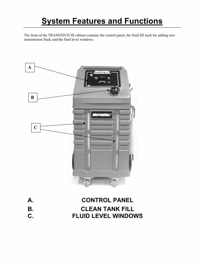
System Features and Functions The front of the TRANSTECH III cabinet contains the control panel, the fluid fill neck for adding new transmission fluid, and the fluid level windows.
A. CONTROL PANEL B. CLEAN TANK FILL C. FLUID LEVEL WINDOWS
A
B
C

Front View - Control Panel Features and Functions
A. Vacuum-Off-Fill Switch.
Turns on pump and activates valves to initiate vacuum, Fill or turn unit off.
B. Vacuum light
Illuminates when unit is powered in vacuum mode.
C. Empty Waste switch
Turns on pump and activates valves to evacuate the waste
capture tank fluid.
D. Circuit Breaker 15 amp circuit breaker to protect unit from overloads.
E. Fill light
Illuminates when unit is powered in Fill mode.
B
A
C
D
E

Right View
A. Service Hose Fluid vacuum & fill supply hose.
B. Quick Coupler Secures the unit’s output hose connection to the adapter for the dipstick tube.
C. Battery Cables
Positive (red) and negative (black) battery connections.
D. Drain tray Adapter storage and excess fluid drain capture.
C
B
A
D

Theory of Operations
Descriptions of the various operations, control buttons, and indicators that make up the control
panel are listed below.
VACUUM-OFF-FILL SWITCH: • When power cord is attached to a good 12 volt source, move the switch to the VACUUM
position to create vacuum on the service hose.
• When the switch is moved to the FILL position, the unit will pump fluid from the clean fluid tank out of the service hose.
EMPTY WASTE SWITCH: • Turn on the EMPTY WASTE SWITCH to pump used fluid out of the service hose.

Safety Information and Precautions
/!\ DANGER Vehicle exhaust gases contain Carbon Monoxide, which is a colorless and odorless lethal gas. Only run engines in well-ventilated areas and avoid breathing exhaust gases. Extended breathing of exhaust gases will cause serious injury or death.
/!\ WARNING
Exhaust gases, moving parts, hot surfaces are present during and after the vehicle’s engine is running. Read and understand the operator’s manual before using the TRANSTECH Service system. When using petroleum products always refer to the MSDS sheets and manufacturer’s instructions for the proper procedure to handle emergency medical treatment, cleanup, handling, and storage requirements. Improper use of the TRANSTECH Transmission Service System or exposure to exhaust gases can cause injury. Spilled transmission fluid on an engine can ignite. Avoid exposure to flames, sparks, hot engine parts, and other ignition sources. Always keep fully charge fire extinguisher nearby. The extinguisher should have a class B rating and be suitable for gasoline, chemical, and electrical fires. Cleanup any oil spills immediately. Dispose of contaminated cleanup material according to governing environmental laws. Never look directly into the air induction plenum or carburetor throat when the engine is operating. Always verify hose connections to the transmission’s oil cooler lines before starting the vehicle’s engine. Explosion or flame or exposure to flammable liquid and vapors can cause injury. Flammable liquid (transmission fluid) can splash out of reservoir when filling or when unit is being moved. Always keep Reservoir Cap secure except when filling reservoir. Explosion or flame can cause injury. Wear safety goggles. Wear chemical resistant gloves when connecting or disconnecting fitting and adapters. Chemicals can cause harmful byproducts - do not add any chemicals to TRANSTECH’s reservoir tank. Use only approved automatic transmission fluid. Do not swallow or ingest any chemicals. Use with adequate ventilation. Avoid breathing vapors. Do not store chemicals in or on the machine (other than automatic transmission fluid). Improper use of transmission fluid can cause injury.

Over exposure can have harmful effect on eyes, skin, respiratory system and possible unconsciousness and asphyxiation. Improperly blocked vehicles can move. Set the parking brake and chock the wheels. Moving vehicles can cause injury. Moving engine parts. The engine cooling fan will cycle on and off depending on the coolant temperature and could operate without the engine running. Wear safety goggles. Always keep objects, clothing, and hands away from the cooling fans and engine parts. Moving engine parts can cause injury. Hot surfaces are present during and after running the engine. Do not contact hot surfaces such as, manifolds, pipes, mufflers, catalytic converters, or radiators and hoses. Hot surfaces can cause injury. Catalytic converters become extremely hot. Do not park a converter-equipped vehicle over dry grass, leaves, paper, or any other flammable material. Do not touch a catalytic converter until the engine has been off for at least 45 minutes. Catalytic converters can cause burns. Cracked fan blade can become airborne. Examine fan blades for cracks. If found, do not service the vehicle. Flying objects can cause injury. Batteries produce explosive gases and can explode, resulting in injury. Wear safety goggles when working on or near batteries. Use in a well-ventilated area. Keep sparks and flames away from the battery and never lay tools, equipment, or other conductive objects on the battery. When is connecting to the battery, make sure the unit’s power switch is off. Connect the positive lead of the unit to the positive lead battery first; connect the negative lead of the unit to a solid ground point as far from the battery as possible. Keep battery acid away from skin or eyes. In case of eye contact, flush with clean water for 15 minutes and get medical attention.

Before You Begin
First Time Operation
NOTE This unit has been tested using Dextron lll Automatic Transmission Fluid, and is ready for service after receiving inspection of the unit. Use new oil above 50 degrees Fahrenheit. Remember to send in your warranty card.
1. Check the service hose, battery connections, and all external components for damage. 2. Fill the unit’s reservoir with 14 quarts (13 liters) of new transmission fluid if you are going to
perform a service now. Otherwise use 8 quarts (7.6 liters). NOTE: The first two quarts in both of the fluid tanks will NOT be visible thru the ‘windows”.
3. Install an adapter wand in the coupler of the service hose. 4. Attach the unit’s Red positive battery clip to vehicle’s 12-volt battery; connect the black negative
battery clip to a solid ground point as far from the battery as possible. 5. Insert the wand into the clean tank fluid far enough to ‘suck’ fluid. Press the VACUUM control
switch. Allow the unit to run until fluid level is visible in waste tank window. Press OFF switch. 6. Remove the wand from the clean fluid tank. Direct the wand tip only back into the clean fluid
tank and press the FILL control switch. Clean fluid should flow out of the wand and into the clean fluid tank. Turn switch to OFF after a solid stream of fluid is observed.
7. Press the EMPTY WASTE button. Fluid should be pumped out of waste fluid tank thru the wand.
Stop the EMPTY WASTE flow when the fluid level in the waste tank gets to ‘zero’. The unit is now primed and ready for service.
8. Disconnect power to machine and check ‘NEW’ tank fluid level, add if necessary.
9. The unit is now ready to perform a service. See service instructions for procedure.
NOTE Steps 3-8 must be performed BEFORE first time operation.

Transmission Service Procedure
Follow the steps below to service the Transmission thru the dipstick tube.
IMPORTANT
Do not perform the transmission service if the vehicle’s engine oil or coolant level is low. If necessary, add motor oil and/or coolant. Do not perform service if new transmission fluid is below 50 degrees Fahrenheit.
/!\ WARNING
Flammable Liquid can squirt out of pressurized lines when connecting or disconnecting. Verify that engine and machine are both off before connecting or disconnecting cooler lines or adapters. Wear safety goggles. Wear chemical resistant gloves when connecting or disconnecting fittings and adapters. Wrap a shop towel around pressure fittings and adapters when disconnecting. Avoid exposure to flames, sparks, hot engine parts, and other ignition sources. Explosion or flame or exposure to flammable liquid and vapors can cause injury.

1. Add the correct amount of automatic transmission fluid into the TRANSTECH’S clean tank reservoir. See chart below:
NOTE: Quantity of fluid used per vehicle may vary depending on the condition of the fluid in the transmission being serviced and the time allowed (engine running) between drain/fill sequences. Trucks and Step Vans may have a larger transmission, therefore may use more fluid than specified in this chart.
2. Start engine, let run until it reaches operating temperature, TURN ENGINE OFF. 3. Remove the vehicles dipstick and insert the wand thru the tube until it reach’s bottom.
Turn on VACUUM switch. Observe the fluid flow thru the transparent hose. a) When the pan is empty, turn OFF VACUUM and turn ON FILL. Observe the
amount of fluid drained into waste capture tank. When that amount has been ‘filled’ turn OFF FILL.
4. In order to do a complete fluid exchange it will be necessary to start the vehicle engine briefly to circulate the fluid from the transmission pan. Repeat the vacuum and fill procedure until fluid is ‘clean’ when doing the vacuum mode.
5. Remove the wand and check the fluid level in the transmission. Adjust as necessary. 6. Transmission Filter Change:
If the vehicle’s transmission filter is to be replaced, perform the VACUUM step before removal of the oil pan.
CAUTION Letting the transmission run for an extended period of time
without fluid can cause serious damage to internal components.
a) Replace or clean the vehicle’s transmission fluid filter and reinstall the transmission’s oil pan following outside manufacturer’s recommendations.
b) Refill the transmission using the FILL procedure. Check and adjust fluid level as needed.
7. Continue with the service until all the dirty fluid in the system has been exchanged. 8. Start engine, let it run for one minute, then check the transmission’s fluid level. Adjust if
necessary.
APPROXIMATED FLUSH CHART 4 Cylinder vehicle 10-12 quarts 6 Cylinder vehicle 12-14 quarts 8 Cylinder vehicle 14-16 quarts

QUESTIONS & ANSWERS 1. How is the clean fluid tank completely emptied in order to change fluid type?
The TransTech 1000 clean tank can be completely emptied. First connect the positive battery cable to a battery’s positive post. Connect the negative battery cable to the battery’s negative post. Install an adapter into the service hose. Insert the hose with adapter into a suitable container to capture the fluid from the clean tank. Turn on the FILL button. When the fluid level gets below the zero tank level tip the unit back until the service hose is discharging air. Turn off FILL. Refill and prime the unit as instructed in “Before you begin”.
2. The TransTech 1000 seems to take longer to perform a service than when it was new.
If it appears that a service now takes longer, inspect the clean tank filter screen for debris. Refer to the unit’s Filter Inspection on page ___.
3. What should I do when the machine will not perform a service?
First refer to the Trouble Shooting section on page 6-1. If you are still unable to correct the problem call MotorVac Technical Support at 1-800-841-8810 for assistance.
4. On what vehicles can the TransTech 1000 be used?
Any vehicle which has a dipstick tube and uses automatic transmission fluid.
5. Does the TransTech 1000 generate pressure that could damage a vehicle in any way?
The Evacuate and Fill procedures are completed with the vehicle engine OFF. If careful control of the fluid level is observed prior to starting the engine there should never be any vehicle damage.

Troubleshooting and Additional Help
Refer to the list below in the unlikely event that you have problems with your TRANSTECH 1000 Transmission Service System.
Problem: Solution:
1. Unit does not power-up.
Inspect circuit breaker, reset if necessary. Check power cord for wiring breaks.
2. Pump runs but is not moving fluid.
Check internal filters for obstruction.
3. Unit works in one mode but not in others.
Possible problem with solenoid valves.
4. Unit will not start. Waste light is on.
Check that waste fluid tank is not full. Level switch located near top of waste fluid tank may be stuck ‘on’.
ADDITIONAL HELP
Please verify that items above have been reviewed before calling for additional assistance. In the unlikely event that problems persist with the unit call Technical Support, have your model and serial numbers available before you call. Remember to send in your warranty card. In the U.S. Canada: (800) 841-8810 Contact your local (714) 558-4822 MotorVac distirbutor

Appendix A - Maintenance
Maintenance Procedures
The following maintenance procedures should be performed on a routine basis: 1. Carefully clean the exterior with a soft cloth to keep the cabinet looking new. Check the cabinet
for dents or impact markings, if found, inspect for damaged components.
2. Check all hoses and wires for cuts or frays.
3. Clean the unit’s filter screens after every 100 services or 6 months, which ever comes first. See the next section for procedure.
Cleaning The Unit’s Filter
1. Disconnect power harness from any power source.
2. Remove the Phillip head screws from the unit’s ‘BELT-LINE’. Tip the top part of the cabinet
housing forward to access inner components. 3. Locate the plastic filters, found at the top of clean fluid tank and the second filter is located at the
front of the tanks. (The front filter is to capture debris from dirty fluid coming out of vehicle.).
4. Hold the filter assembly and ‘unscrew’ the bowl of the filter from the housing.
5. Use a fine pick or bent pin to pull screen away from the filter housing. Clean screen.
6. Assemble in reverse order. NOTE: Use caution not to pinch o’ring on reassembly
7. Enter initials, date, and a check mark in the appropriate boxes of the Maintenance Record at the end of the chapter.
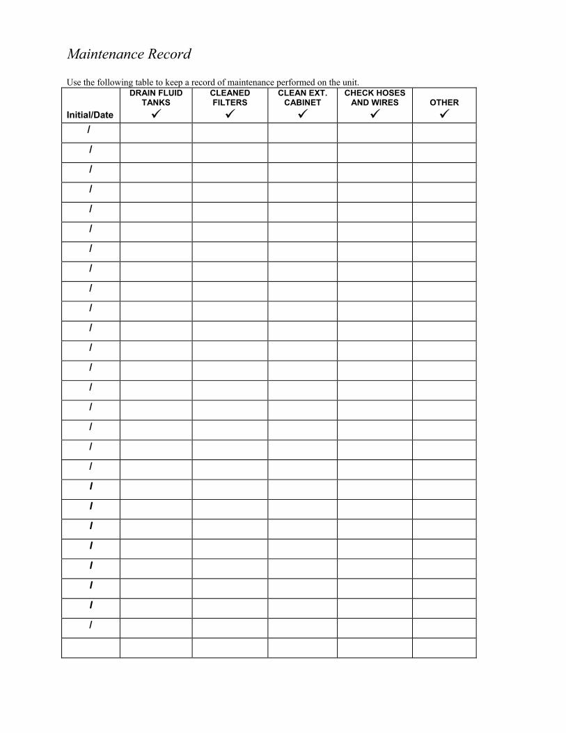
Maintenance Record Use the following table to keep a record of maintenance performed on the unit. Initial/Date
DRAIN FLUID TANKS
CLEANED FILTERS
CLEAN EXT. CABINET
CHECK HOSES AND WIRES
OTHER
/
/
/
/
/
/
/
/
/
/
/
/
/
/
/
/
/
/
I
I
I
I
I
I
I
/

TransTech System Accessories
Standard Adapter: TransTech 1000 Service Unit
PART & NUMBER QTY DESCRIPTION
060-xxxx
1
36 inch WAND adapter
(1/4” tubing)
ORDERING PARTS
Parts for the unit may be ordered by calling Customer Service, have your model and serial numbers available:
Call: 800.841.8810, 714.558.8810

Appendix C – Parts
Service Parts for the TRANSTECH III Transmission System. Please refer to the part numbers below when ordering parts for this unit.
Part # Description 010-0027 Wheel (8 x 1.75) 010-0026 Hub cap (Black Plastic) 040-0604 Cap Nut (½” ID – Push 0n) 040-0507 Axle Bushing (Black Nylon) 010-5500 Axle, Rear Wheels (½” x 20.875 lg.) 010-6100 Swivel caster 010-6101 Swivel caster with brake lock 010-5004 Hose bracket 010-5602 Adapter Box with bottle (010-1052) 040-1200 Screw 5/8 php x #6 (for adapter box) 040-2000 Flat washer #6 (for adapter box) 040-2200 Threaded Standoff (for adapter box) 010-6060 Reservoir cap 020-8043 Harness, External Power 020-1604 Internal Light / LED TYPE 040-0612 Screw, Allen Head, ¼-20 x ½ (Handle) 040-0613 Screw, Phillips, stainless steel 6-32 (Rear panel) 040-0623 Screw, Allen Head, 8-32 x 5/8 (Control Panel) 050-1000 Screen filter inline ½ MPT. Pp. 200-8665 Output/Return hose assembly / Clear - braided (ONE) 080-0236 Female Quick Disconnect, ¼ m / barb, Brass 080-6009 Hose Clamp, ( Crimp Style, Steel ) 100-1010 Operators Manual 200-xxxx Quick Reference Card
ORDERING PARTS Parts for the unit may be ordered by calling Customer Service, have your model and serial numbers available: inside U.S.A. Canada: (800) 841-8810 Contact your local (714) 558-4822 MotorVac distributor


![[XLS]minoritywelfare.bih.nic.inminoritywelfare.bih.nic.in/scholarships/PreMatric/Fresh... · Web view1 1000 0 0 1000 2 1000 0 0 1000 3 1000 0 0 1000 4 1000 0 0 1000 5 1000 0 0 1000](https://img.pdfslide.net/doc/110x75/5ab4f6537f8b9a7c5b8c491e/xls-view1-1000-0-0-1000-2-1000-0-0-1000-3-1000-0-0-1000-4-1000-0-0-1000-5-1000.jpg)