Embed Size (px)
Citation preview

University of Nebraska - LincolnDigitalCommons@University of Nebraska - LincolnBiological Systems Engineering: Papers andPublications Biological Systems Engineering
6-1981
Mound Sewage Waste Treatment SystemsElbert C. DickeyUniversity of Nebraska at Lincoln, [email protected]
Phillip W. HarlanUniversity of Nebraska-Lincoln
Cheryl Kisling-CrouchUniversity of Nebraska-Lincoln
Follow this and additional works at: https://digitalcommons.unl.edu/biosysengfacpub
Part of the Biological Engineering Commons
This Article is brought to you for free and open access by the Biological Systems Engineering at DigitalCommons@University of Nebraska - Lincoln. Ithas been accepted for inclusion in Biological Systems Engineering: Papers and Publications by an authorized administrator ofDigitalCommons@University of Nebraska - Lincoln.
Dickey, Elbert C.; Harlan, Phillip W.; and Kisling-Crouch, Cheryl, "Mound Sewage Waste Treatment Systems" (1981). BiologicalSystems Engineering: Papers and Publications. 266.https://digitalcommons.unl.edu/biosysengfacpub/266

•
~~ ··---. ~--n-:r __
---•+,.ENS\O~----
G81-559
Mound Sewage Waste Treatment Systems
Elbert C. Dickey, Extension Agricultural Engineer-Conservation Phillip W. Harlan, Extension Agronomist (Land Use)
Cheryl Kisling-Crouch, Technical Writer, Agricultural Engineering
Several areas in Nebraska are not appropriate for onsite home sewage treatment using conventional septic tank absorption field systems. Site factors that limit the use of conventional absorption fields include slowly permeable soils, shallow or gravelly soils and high water tables. The septic tank-mound system, which consists of a septic tank for primary sewage treatment and a constructed mound for final waste treatment was developed to overcome these site limitations (Figure 1).
Figure I. Mound waste treatment system for home sewage.
Although mound systems differ only slightly in principle from conventional sewage systems, they allow the user to select suitable materials to build an absorption field that relies on evapotranspiration as well as the absorption capacity of existing soil. A pump located in a chamber is generally recommended to distribute the effluent evenly in the mound.
Mound location, size and shape, construction proce-
dures, distribution of effluent, and dosing quantity all interact in determining how well the mound will function . Each component must be properly designed and constructed to prevent premature failure of the system .
Mound Location
The septic tank-mound system can be constructed on soils having percolation rates from 0 to 120 minutes per inch (0 to 48 min/ em); the traditional septic tank-absorption field system is limited to soils with percolation rates from 5 to 60 minutes per inch (2 to 24 min/em) . Ideally, the mound should be constructed on the flat area of a hill crest. Other flat areas that do not receive drainage water from surrounding land are also suitable.
Gently sloping areas can be used if the soils have minimum percolation rates shown in Table I . Do not locate the mound on a natural slope exceeding 12 percent under any soil condition, and do not move or grade the soil to change the ground slope.
Table I. Required percolation rates for constructing a mound on various slopes.
Slope percent
0·3 3-6 6-12 over 12
Percolation rate•
Minutes per inch (em)
120 (48) 60 (24) 30 (12)
unacceptable for mound
*Percolation rates are for all layers of natural or fill soil to a depth of 24 inches (61 em) below the mound .
A mound system cannot be used in areas subject to frequent flooding because of possible downstream water contamination. Areas where a seasonal water table, rock formation or impervious stratum occurs
D-5
within 24 inches (61 em) of the soil surface should also be avoided, since ground water close to the soil surface could be contaminated. Greater distances will further reduce the possibility of contamination. The mound absorption area should be at least 100 feet (30 m) down slope from any well or spring, 50 feet (15 m) from streams, 5 feet (1.5 m) from property lines, and 10 feet (3 m) from the drip area of trees.
Sizing the MotJnd and ~ptic Tank
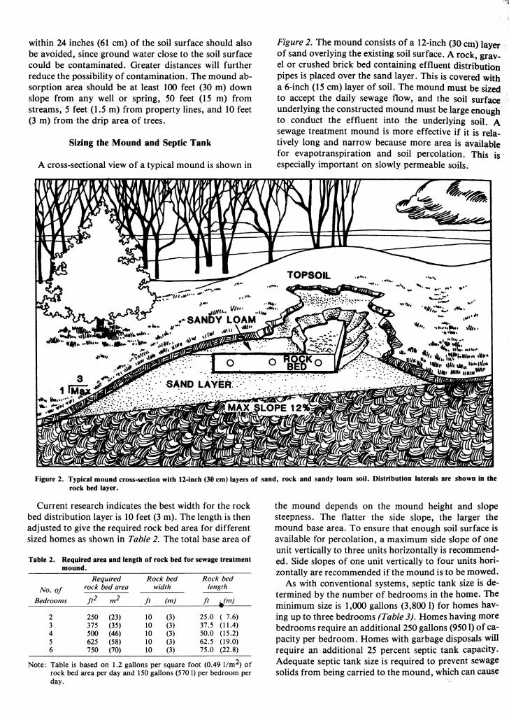
A cross-sectional view of a typical mound is shown in
Figure 2. The mound consists of a 12-inch (30 em) layer. of sand overlying the existing soil surface. A rock, gravel or crushed brick bed containing effluent distribution pipes is placed over the sand layer. This is covered with a 6-inch (15 em) layer of soil. The mound must be sized to accept the daily sewage flow, and the soil surface underlying the constructed mound must be large enougt{ to conduct the effluent into the underlying soil. A sewage treatment mound is more effective if it is relatively long and narrow because more area is available for evapotranspiration and soil percolation. This is especially important on slowly permeable soils.
...... ....... ···~· •..
.... :.:~; .. ... ,.,, ... ~. .. .:.:·~- .,.,.. ~· .,,.. ..... ... ...... ~~ "' .... . ''• ......... JirN, '"'' • ••••• ....... , ..... . •.. ~.~ ..... ..
~. ""·· ;flti'~ ...... .-... 'WIIr ~Mf• llfr,.t ... hltl••
•u•••""'
Figure 2. Typical mound cross-section with 12-inch (30 em) layers of sand, rock and sandy loam soil. Distribution laterals are .shown in the rock bed layer.
Current research indicates the best width for the rock bed distribution layer is 10 feet (3m). The length is then adjusted to give the required rock bed area for different sized homes as shown in Table 2. The total base area of
Table 2. Required area and length of rock bed for sewage treatment mound.
Required Rock bed Rock bed
No. of rock bed area width length
Bedrooms Jtl m2 ft (m) ft i.(m)
2 250 (23) 10 (3) 25.0 ( 7.6) 3 375 (35) 10 (3) 37.5 (11.4) 4 500 (46) 10 (3) 50.0 (15.2) 5 625 (58) 10 (3) 62.5 (19.0) 6 750 (70) 10 (3) 75.0 (22.8)
Note: Table is based on 1.2 gallons per square foot (0.49 11m2) of rock bed area per day and 150 gallons (570 I) per bedroom per day.
the mound depends on the mound height and slope steepness. The flatter the side slope, the larger the mound base area. To ensure that enough soil surface is available for percolation, a maximum side slope of one unit vertically to three units horizontally is recommended. Side slopes of one unit vertically to four units horizontally are recommended if the mound is to be mowed.
As with conventional systems, septic tank size is determined by the number of bedrooms in the home. The minimum size is 1,000 gallons (3,800 1) for homes having up to three bedrooms (Table 3). Homes having more bedrooms require an additional 250 gallons (950 l) of capacity per bedroom. Homes with garbage disposals will require an additional 25 percent septic tank capacity. Adequate septic tank size is required to prevent sewage solids from being carried to the mound, which can caus.e
premature failure. Septic tanks must be watertight and constructed of a durable material that will not buckle or crack from soil pressures or during construction, and that will not corrode.
Table 3. Septic tank and pumping chamber sizes.
No. of Septic Tank* Pumping Chamber
Bedrooms gallons (liters) gallons (liters)
2 1,000 (3,790) 250-500 (950-1 ,900)
3 1,000/ (3,790) 500-750 (I ,900-2,850)
4 1,250 (4,340) 500-750 (I ,900-2,850)
5 1,500 (5,680) 750-1,000 (2,850-3,790) 6 1,750 (6,630) 750-1,000 (2;850-3,790)
• Add 25 percent capacity for garbage disposal.
Effluent Distribution within the Mound
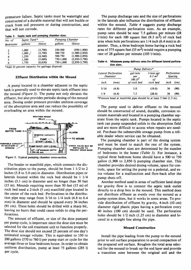
A pump located in a chamber adjacent to the septic tank is generally used to elevate septic tank effluent into the mound (Figure 3). The pump not only elevates the effluent, but also provides periodic dosing of the mound area. Dosing under pressure provides uniform coverage of the absorption area and can reduce the possibility of overloading an area within the mound.
FROM SEPTIC TANK-
Figure 3. Typical pumping chamber cross-section.
-TO MOUND
CHECK VALVE MAY BE INSTALLED TO
PREVENT DRAIN BACK
The header or manifold pipe, which connects the distribution pipes to the pump, should be from 1 1/2 to 2 inches (3.8 to 5.0 em) in diameter. Distribution pipes or laterals located within the rock bed should be 1 114 inches (3.1 em) in diameter and no longer than 50 feet (15 m). Mounds requiring more than 50 feet (15m) of rock bed need a 2-inch (5 em) manifold pipe located in the center of the rock bed. Perforations in the distribution pipe may range from 3116 to 114 inch (4.8 to 6.4 mm) in diameter and should be spaced every 36 inches (91 em). These holes should be drilled with a sharp bit, leaving no burrs that could cause solids to clog the perforations.
The amount of effluent, or size of the dose pumped per pump cycle, is important since the dose size must be selected for the soil treatment unit to function properly. The dose size should not exceed 25 percent of one day's estimated sewage volume. This is equivalent to 150 to 200 gallons (570 to 760 1) per pump start or cycle for the average three or four bedroom house. In order to obtain uniform distribution, pump at least 75 gallons (285 l) per cycle.
The pump discharge rate and the size of perforations in the laterals also influence the distrib1,1tion of effluent within the mound. Table 4 suggests pump discharge rates for different perforation sizes. As an example, pump rates should be near 7.5 gallons ~er minute (28 l!min) for each 100 square feet (9.3 m ) of rock bed area when hole perforations are 114 inch (6.4 mm) in diameter. Thus, a three bedroom home having a rock bed area of 375 square feet (35 m2) would require a pumping rate of 28 gallons per minute (105 1/min).
Table·4; Minim111ft1Jump delivery rates for different lateral perforation sizes.
Pump Delivery*
Lateral Perforation gal/min tlmin Pr Perforation Diameter per 9.3 m Spacing
JOOf~ of inch (mm) of rock bed rock Qed inch (em)
3/16 (4.8) 5.0 (19.0) 36 (90)
1/4 (6.4) 7.5 (28.0) 36 (90)
*Pressure head at manifold pipe should be at least 5 feet (1.5 m).
The pump used to deliver effluent to the mound should be constructed of sound, durable, corrosion resistant materials and located in a pumping chamber separate from the septic tank. Pumps located in the septic tank can pump suspended solids to the absorption field and are more difficult to access when repairs are needed. Purchase the submersible sewage pump from a reliable dealer where service can be obtained.
The pumping chamber is part of the dosing system and must be sized to match the rest of the system. Pumping chamber sizes are determined by the number of bedrooms in the home (Table 3). For instance, a typical three bedroom home should have a 500 to 750 gallon (1,900 to 2,850 I) pumping chamber size. This chamber provides desired dosing volume, space for controls, space for setting the pump on a pedestal, and extra volume for a malfunction and flow-back after the pump shuts off.
Another method used in areas of sufficient land slope for gravity flow is to connect the septic tank outlet directly to a drop box in the mound. This method does not distribute effluent as evenly over the mound as a pump system does, but it works in some areas. To provide distribution of effluent by gravity, 4-inch (10 em) diameter rigid plastic pipes having a perforation every 40 inches (100 em) should be used. The perforation holes should be 112 inch (1.25 em) in diameter and located in a straight line along the pipe.
Mound Construction
Install the pipe leading from the pump to the mound prior to soil surface preparation to avoid compaction of the prepared soil surface. Roughen the total ar~a selected for the mound to break up the sod layer and provide a transition zone between the original soil and the
mound fill material. The soil should only be worked when dry and friable. If a segment of the soil can be rolled into a "wire" 118 inch (3 mm) in diameter, the moisture content is too high for the soil to be worked and construction should be delayed until more favorable soil conditions exist. Use a moldboard plow for surface preparation as other implements tend to compact the soil.
Plowing should be done on the contour to a depth of 8 inches (20 em) with the soil thrown upslope. Avoid leaving a dead furrow under the mound since it may serve as a channel for effluent to flow away from the area. If the soil percolation rate to a depth of 8 inches (20 em) is faster than 15 minutes per inch (5.9 min/em), a disk may be used instead of a moldboard plow to roughen the soil surface. Backhoe teeth may also be used but extreme caution must be exercised to avoid compacting deeper soil layers. Never use a front-end loader to clear the area of the sod layer for mound construction. Removing site vegetation with the loader may compact the soil surface and reduce the rate of percolation.
Proceed with the mound construction as soon as possible after preparing the soil surface. Make every effort to keep rain from falling on the prepared site.
After completing the soil preparation, place a clean sand layer at least 12 inches (20 em) deep over the roughened area. The sand must be 25 percent coarse sand (.5 to 1 mm), less than 50 percent fine sand (.05 to .25 mm), and no more than 10 percent of the particles smaller than .05 mm. Use a crawler tractor with a blade or bucket to place the sand since a rubber tired loader will cause compaction of the roughened surface. Make sure at least 6 inches (15 em) of sand is kept under the tracks at all times to reduce compaction.
After installing the sand layer, add a 9-inch (23 em) layer of gravel, crushed brick or similar insoluable rock. Select materials that are durable, decay resistant, and free from dust, sand, silt or clay. Crushed limestone is not suitable rock because of its solubility. The size of the rock should be 3/4 inch to 2 1/2 inches (1.9 to 6.4 em) in diameter.
Install the distribution pipe network level with the perforations downward. The laterals may be spaced up to 40 inches (100 em) on center. Do not place laterals within 20 inches (50 em) of the edge of the rock bed.
For gravity flow systems, the pipe is laid with 2 inches of drop in every 100 feet (1 cm/6 m) away from the distribution box to which they are connected. Although three laterals are used for pump distribution systems,
Extension work in" Agriculture, Home Economics and subjects relating
thereto," The Cooperative Extension Service, Institute of Agriculture and Natural Resources,
University of Nebreska-Lincoln, Cooperating with the Counties and the U.S. Department of Agriculture
Leo E. Lucas, Director
only two are required for gravity flow systems. The pipes should be approximately 60 inches (152 em) apart and no closer than 30 inches (76 em) from the edge of the rock bed.
Place at least 3 inches (7.6 em) of rock bed material over the pipes, and a 3- to 4-inch (7 .6 to 10 em) layer of straw or marsh hay over the rock bed to prevent the soil cover from filtering into the rock. An alternative to hay or straw is untreated building paper (red rosin).
The mound is completed by placing a layer of sandy loam soil over the rock bed. The soil should be 12 inches (30 em) deep in the center of the rock bed and 6 inches (15 em) at the edge. A 6-inch (15 em) layer of top soil is placed over the entire mound with a grass vegetative cover being established to prevent soil erosion and aid in evapotranspiration.
Landscaping
The mound can be shaped in a variety of ways to suit individual landscaping and lot size needs. Properly la~dscaped areas around the mound can serve as a privacy barrier, a windbreak for homes, and to screen unsightly views. Building a contoured mound works well for hillsides, while one built on a right angle can be placed on a corner. A rectangular mound is acceptable for uniform slope locations.
Since mounds tend to be dry on top, plant grasses and other ornamental ground covers that are resistant to water stress there. Plant cool-season grasses and other plants on the sides. Shrubs should never be planted at the top of the mound but may be placed at the foot or side slopes. Do not plant or leave large trees near the mound because of the possibility of damage caused by root growth.
Keep activities on the mound to a minimum to prevent soil compaction or loss of absorption capacity. Never drive across the mound and do not mow it if the soil is wet. If these precautions are taken, the mound should continue to be useful for many years.
Some maintenance of the septic tank, consisting of inspections and sludge removal, is required to prevent solids from entering the mound. Frequency of tank cleaning depends on its capacity and how much solid material it is expected to digest. For a three bedroom home, a 1,000 (3,800 1) gallon tank should be cleaned every 3 to 5 years. Smaller tanks must be cleaned more often. (See NebGuide 79-446, "Maintaining a Septic Tank System.")
The Cooperative Extension Service provides information and educational programs to all people without regard
to race, color or national origin.
File under: WASTE MANAGEMENT D-5, Home Waste Systems
Issued June 1981, 15,000