Embed Size (px)
Citation preview

Ord Mountain Solar 2.0 Project Description Environmental Impact Report
San Bernardino County 2‐9
Two new 220‐kV transmission lines, to loop the Calcite Substation into the existing Lugo‐Pisgah
No. 1 220‐kV transmission line, would each extend approximately 2,500 feet south of the Calcite
Substation, cross under SCE’s Eldorado‐Lugo and Lugo‐Mohave 500‐kV lines, and enter the
substation from the south. The existing 12‐kV distribution circuit would be extended to provide
temporary power and permanent Calcite Substation light and power westward overhead on
Haynes Road, for approximately 2,000 feet. The circuit would then continue underground for
approximately 2,100 feet heading westward under the existing transmission right‐of‐way (ROW)
along Haynes Road and then north along the new Calcite Substation access road into the light and
power rack within the substation.
The telecommunication fiber‐optic cables would connect the proposed Calcite Substation to SCE’s
Barstow Repeater Communication Site and to a splice box on tower M29‐T3 on SCE’s Lugo‐Mohave
500‐kV transmission line.
PROJECT SETTING AND EXISTING CONDITIONS
ORD MOUNTAIN SOLAR AND ENERGY STORAGE PROJECT
The site of the proposed solar and energy storage project would be in proximity to an existing high‐
voltage transmission corridor and SCE’s proposed Calcite Substation. The Calcite Substation is a
required component necessary for the operation of the solar facility. In addition to the proposed
project site’s proximity to the Calcite Substation, other reasons for selecting the project site include
the fallow nature of the project site because of previous agricultural uses; the project site’s
proximity to existing roads, reducing the need for construction of new roads; and the site’s location
in an area with excellent solar irradiance.
The project site is generally flat and slopes from northwest to southeast, with elevations of
approximately 2,980 to 2,900 feet above mean sea level. Locally, the proposed solar and energy
storage project would be accessed via SR 247 and an internally constructed road system. The
project area would include the approximately 0.6‐mile gen‐tie overhead transmission line from the
proposed solar and energy storage project’s on‐site substation to the proposed Calcite Substation.
The solar and energy storage project site comprises fallow agricultural fields with some early
succession saltbush scrub vegetation in isolated patches, which for the most part, has been
degraded due to the agricultural use and livestock grazing on the site. The transmission line would
traverse undeveloped Mojave creosote bush scrub and desert saltbush scrub.
The geology of the proposed solar and energy storage project property and surrounding vicinity is
characterized as a veneer of quaternary alluvium overlying Mesozoic‐age granite and quartz
monzonite intruded into Paleozoic metasedimentary rocks. Historically, agricultural irrigation wells
have been completed in the alluvium overlying basement granitic and metasedimentary rock. The

Ord Mountain Solar 2.0 Project Description Environmental Impact Report
San Bernardino County 2‐10
1996 Mojave Basin area adjudication created the Este subarea, which includes the Lucerne Valley
groundwater basin and the Fifteen Mile Valley groundwater basin. The proposed solar and energy
storage project site is located in the Lucerne Valley groundwater basin, encompassed by the Este
subarea of the Mojave Basin judgement area. The most prolific aquifer material of the Lucerne
Valley groundwater basin is the quaternary alluvium, comprising unconsolidated to semi‐
consolidated boulders, gravel, sand, silt, and clay. Based on well completion reports provided by
the Department of Water Resources (DWR), the alluvium of the proposed solar and energy storage
project boundary ranges from 165 to 330 feet in thickness.
The area surrounding the project site is characterized by rural desert terrain modified by power
lines, roads, fallow agricultural fields, and scattered residences located throughout. The
surrounding area is also dominated by the SR 247 transportation corridor running north–south just
to the west of the proposed solar and energy storage site and east of the proposed Calcite
Substation site. In addition to electrical and transportation infrastructure, there are 32 single‐family
rural residential structures located within 0.5 mile of the proposed project boundary. These
residences are scattered throughout the area and many of the parcels are currently used as storage
space for vehicles and/or machinery.
Existing land uses and Land Use Zoning Districts on and adjacent to the proposed solar and energy
storage project site are listed in Table 2‐1, Existing Land Use and Land Use Zoning Districts; see
Exhibit 4, Land Use Zoning Districts.
Table 2‐1:
Existing Land Use and Land Use Zoning Districts
Location Existing Land Use Land Use Zoning District
Ord Mountain Solar Energy and Storage Project
Proposed Solar Site Agriculture (fallow) LV/AG (Lucerne Valley/Agriculture); LV/AG‐40
Gen‐Tie Agriculture (fallow)/SCE Transmission LV/AG; LV/AG‐40
On‐Site Substation Vacant LV/AG‐40
North Agriculture (fallow) LV/AG‐20/AG‐40
South Residential, Agriculture (fallow) LV/AG
East Residential, Agriculture (fallow) LV/RL/RC (Rural Living/Resource Conservation)
West Agriculture (fallow) LV/AG‐20/AG‐40; LV/RC

Ord Mountain Solar 2.0 Project Description Environmental Impact Report
San Bernardino County 2‐11
Location Existing Land Use Land Use Zoning District
Calcite Substation
Calcite Substation Vacant LV/AG‐40
North Agriculture (fallow) LV/AG‐40
South Agriculture (fallow) LV/AG‐40
East Residential, Agriculture (fallow) LV/AG
West Agriculture (fallow) LV/AG‐40
Source: San Bernardino County Land Use Services Department 2016

Ord Mountain Solar 2.0 Project Description Environmental Impact Report
San Bernardino County 2‐12
This page is intentionally blank.

ORD MOUNTAIN SOLAR PROJECT ENVIRONMENTAL IMPACT REPORTLand Use Zoning Districts
1/25/2
018 J
N M:
\Mda
ta\Or
d Mou
ntain
Solar
Proj
ect\2
-4 La
nd U
se Zo
ning D
istric
ts.mx
d
Source: San Bernardino County, ESRI USA Topographic Basemap° 0 0.50.25
Miles
LegendProject SiteLV/AGLV/AG-20LV/AG-40LV/RCLV/RL
Exhibit 2-4
1/25/2
018 J
N M:
\Mda
ta\Or
d Mou
ntain
Solar
Proj
ect\2
-4 La
nd U
se Zo
ning D
istric
ts.mx
d

Ord Mountain Solar 2.0 Project Description Environmental Impact Report
San Bernardino County 2‐14
This page is intentionally blank.

Ord Mountain Solar 2.0 Project Description Environmental Impact Report
San Bernardino County 2‐15
CALCITE SUBSTATION
The location of the proposed Calcite Substation was selected based on numerous engineering
factors, including the site’s proximity to the existing Lugo‐Pisgah No. 1 220‐kV transmission line and
the transmission corridor. Access to the site is available from existing roads. The proposed
substation site is relatively flat with elevations of approximately 2,980 feet to 2,900 feet above
mean sea level. Locally, the Calcite Substation would be accessed via SR 247 and the proposed
access road network. The proposed Calcite Substation project area would include two loop‐in
transmission lines, each approximately 2,500 feet from the existing Lugo‐Pisgah 220‐kV
transmission line to the substation.
The geology of the proposed Calcite Substation project property and surrounding vicinity is
consistent with that described for the proposed solar and energy storage project site.
The existing Land Use Zoning District on the proposed Calcite Substation project site is LV/AG‐40,
with portions of the existing transmission corridor recognized as electrical power facilities.
PROJECT OBJECTIVES
A clear statement of project objectives allows for the formulation and analysis of a reasonable
range of project alternatives which must be analyzed pursuant to CEQA Guidelines Section 15126.6.
The project alternatives (see Section 7.0, Alternatives) were developed to feasibly attain most of
the basic project objectives while avoiding or substantially lessening at least some of the significant
effects identified in Sections 3.1 through 3.11.
The objectives of the proposed project include the following:
1. Construct and operate a solar energy facility capable of producing up to 60 megawatts of
electricity to help meet the State‐mandated Renewables Portfolio Standard (RPS) of
providing 33 percent renewable energy by 2020 and 50 percent by 2030.
2. Construct and operate a solar power facility with minimal impacts to the environment.
3. Develop a utility‐scale solar energy facility project that improves local electricity reliability
for the San Bernardino region by providing a source of local generation near the Calcite
Substation.
4. Help reduce reliance on foreign sources of fuel.
5. Supply on‐peak power to the electrical grid in California.
6. Help the State of California meet its statutory and regulatory goal of increasing renewable
power generation, including greenhouse gas reduction goals of Assembly Bill (AB) 32
(California Global Warming Solutions Act of 2006).
Ord Mountain Solar 2.0 Project Description Environmental Impact Report
San Bernardino County 2‐16
7. Contribute to San Bernardino County’s economic growth and reputation as a region rich
with renewable energy development.
8. Sustain and stimulate the economy of Southern California by helping to ensure an adequate
supply of renewable electrical energy while simultaneously creating additional construction
and operations employment and increased expenditures in many local businesses.
9. Provide a new source of energy storage that assists the state in achieving or exceeding the
energy storage target of 1.3 gigawatts of energy by 2020, consistent with the terms of
AB 2514.
The objectives of SCE’s proposed Calcite Substation include the following:
10. Provide transmission access to the Ord Mountain Solar Project, within close proximity to
existing transmission lines and in a manner that reduces the need for additional generation
interconnection collector substations.
11. Complete Calcite Substation construction in a timely fashion, in order to meet the Ord
Mountain Solar Project’s Large Generation Interconnection Agreement (LGIA) target dates.
2.2 PROJECT CHARACTERISTICS
ORD MOUNTAIN SOLAR AND ENERGY STORAGE PROJECT
The proposed solar and energy storage project consists of the following components:
Solar energy generation system
On‐site substation
Energy storage system
Generation tie line
Ancillary facilities
SOLAR ENERGY GENERATION SYSTEM
The proposed solar and energy storage project includes a 60‐MW solar power generating
installation built over a 10‐month period. The 484‐acre site would house all structures, including
solar panels, tracking/support structures, inverters, SCADA, and interconnection facilities (on‐site
substation), all of which would be enclosed by a perimeter security fence. The proposed site plan
is shown in Exhibit 2‐3, Solar Field Site Plan. Solar energy would be captured by an array of
approximately 250,000 photovoltaic panels mounted to a single‐axis tracking system. The high‐

Ord Mountain Solar 2.0 Project Description Environmental Impact Report
San Bernardino County 2‐17
efficiency commercially available PV panels convert incoming sunlight to direct current (DC)
electrical energy.
The panels are arranged in series to effectively increase output voltage to approximately 1,500
volts. These series chains of panels are called “strings” in industry terms, and they provide the basic
building block of power conversion in the solar array. The strings are combined in the solar field via
an above‐ or belowground DC collection system and then further ganged together at the inverter
stations, where the energy is converted to alternating current (AC) and then stepped to an
intermediate voltage, typically 34.5 kV. The chosen PV panels would either be crystalline silicon or
thin film and would be well suited for the desert environment because of their durability and
reliability.
The tracking system would be supported, when practical, by driven piers (piles) directly embedded
into the ground and would be parallel to the ground. The system would rotate slowly throughout
the day at a range of ±60 degrees facing east to west to stay perpendicular to the incoming solar
rays so that production can be optimized.
Each tracker would hold approximately 80 to 90 panels (depending on final configuration) and at
its highest rotated edge would have a maximum height of approximately 12 feet above grade,
depending on the dimensions of the chosen panel. The minimum clearance from the lower edge
of the panel to ground level is approximately 18 to 24 inches, pending final design.
The inverter stations would be up to 12 feet in height and perform three critical functions for the
solar plant: (1) collect DC power in a central location, (2) convert the DC power to AC power, and
(3) convert low‐voltage AC power to medium‐voltage AC power. The inverter stations are typically
open‐air and well suited for the desert environment. The stations consist of DC collection
equipment, utility‐scale inverters, and a low‐ to medium‐voltage transformer. The output power
from the inverter stations is then fed to the AC collection system via an above‐ or belowground
collection system. This AC collection system would deliver the electricity to the on‐site substation,
where the voltage would be stepped up to the interconnection voltage.
ON‐SITE SUBSTATION
The on‐site substation for the proposed solar and energy storage project is the termination point
of the collection system of 34.5 kV of electricity. The output of the entire field is passed through a
final interconnection step‐up transformer to convert it to the grid tie voltage at 220 kV.
Additionally, the proposed solar and energy storage project on‐site substation would host the grid
intertie safety equipment and switches required to interconnect to the high‐voltage transmission
system. The open air on‐site substation would be constructed on the southern border of the solar
array nearest the proposed SCE Calcite Substation.

Ord Mountain Solar 2.0 Project Description Environmental Impact Report
San Bernardino County 2‐18
The footprint of the on‐site substation would be approximately 150 feet by 230 feet. The proposed
solar and energy storage project on‐site substation would consist of components approximately
25 feet tall, with lightning protection masts up to 70 feet tall and a dead‐end “H” frame structure
up to 65 feet in height with masts to 70 feet. Feeders would be overhead lines constructed with
45‐ and 60‐foot‐tall poles for the single and double circuits, respectively.
ENERGY STORAGE SYSTEM
Adjacent to the on‐site substation, an energy storage system is proposed to provide a maximum
capacity of 60 MW over a 4‐hour period (240 MWhs). The energy storage batteries would be
housed in a structure of approximately 35,000 square feet. The structure’s height would be
approximately 20 feet. The batteries would be housed in open‐air style racking (similar to computer
racking) 7 to 9 feet high. The associated inverters, transformers, and switchgear would be located
immediately adjacent to the structure on concrete pads or on driven piles.
The energy storage equipment would be enclosed in a structure that would also have a fire rating
in conformance with County standards and have specialized fire suppression systems installed for
the battery compartments. The structure would also have heating, ventilation, and air conditioning
(HVAC) cooling in areas with batteries to maintain energy efficiency. Power to the HVAC, lighting,
etc., would be provided via a connection to the on‐site station service transformer with connection
lines installed above and/or below ground. The energy storage system would be unstaffed and
would have remote operational control, with periodic inspections/maintenance performed as
necessary.
GENERATION TIE LINE
The energy would be transported from the on‐site substation to SCE’s proposed Calcite Substation
via a generation tie transmission line (gen‐tie line). The gen‐tie line would extend approximately
0.6 mile to the southwest, from the facility’s on‐site substation to the proposed Calcite Substation;
see Exhibit 2‐5, Calcite Substation. The 220‐kV gen‐tie transmission line would consist of
approximately seven spans on up to 150‐foot‐tall concrete or steel poles, spaced an average of
every 500 feet. The poles would carry 336 aluminum conductor steel reinforced (ACSR), or
equivalent, conductors, one conductor per phase, and would allow the line to maintain a minimum
30‐foot vertical clearance to the ground. The number of and height of the poles, as well as the type
of conductor, would be finalized during detailed design. At the Ord Mountain project site, the
height of on‐site poles would be approximately 100 feet. Except for the pole or lattice steel tower
closest to the connected Calcite Substation, all poles would be constructed by the applicant as part
of the proposed Ord Mountain Solar and Energy Storage Project. The right‐of‐way is expected to
be up to 50 feet wide for the maintenance road and the gen‐tie line. Less width may be required
Ord Mountain Solar 2.0 Project Description Environmental Impact Report
San Bernardino County 2‐19
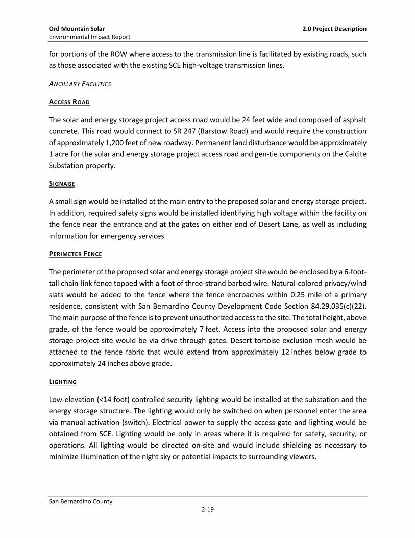
for portions of the ROW where access to the transmission line is facilitated by existing roads, such
as those associated with the existing SCE high‐voltage transmission lines.
ANCILLARY FACILITIES
ACCESS ROAD
The solar and energy storage project access road would be 24 feet wide and composed of asphalt
concrete. This road would connect to SR 247 (Barstow Road) and would require the construction
of approximately 1,200 feet of new roadway. Permanent land disturbance would be approximately
1 acre for the solar and energy storage project access road and gen‐tie components on the Calcite
Substation property.
SIGNAGE
A small sign would be installed at the main entry to the proposed solar and energy storage project.
In addition, required safety signs would be installed identifying high voltage within the facility on
the fence near the entrance and at the gates on either end of Desert Lane, as well as including
information for emergency services.
PERIMETER FENCE
The perimeter of the proposed solar and energy storage project site would be enclosed by a 6‐foot‐
tall chain‐link fence topped with a foot of three‐strand barbed wire. Natural‐colored privacy/wind
slats would be added to the fence where the fence encroaches within 0.25 mile of a primary
residence, consistent with San Bernardino County Development Code Section 84.29.035(c)(22).
The main purpose of the fence is to prevent unauthorized access to the site. The total height, above
grade, of the fence would be approximately 7 feet. Access into the proposed solar and energy
storage project site would be via drive‐through gates. Desert tortoise exclusion mesh would be
attached to the fence fabric that would extend from approximately 12 inches below grade to
approximately 24 inches above grade.
LIGHTING
Low‐elevation (<14 foot) controlled security lighting would be installed at the substation and the
energy storage structure. The lighting would only be switched on when personnel enter the area
via manual activation (switch). Electrical power to supply the access gate and lighting would be
obtained from SCE. Lighting would be only in areas where it is required for safety, security, or
operations. All lighting would be directed on‐site and would include shielding as necessary to
minimize illumination of the night sky or potential impacts to surrounding viewers.

Ord Mountain Solar 2.0 Project Description Environmental Impact Report
San Bernardino County 2‐20
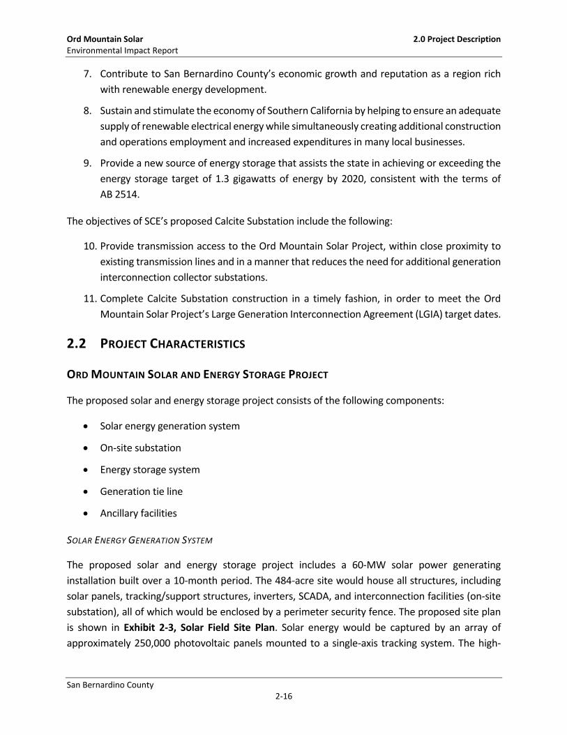
CALCITE SUBSTATION
The proposed Calcite Substation project consists of the following components (see Exhibit 2‐5):
Calcite Substation
Loop‐in transmission line
Telecommunication facilities
Ancillary facilities
CALCITE SUBSTATION
The proposed Calcite Substation would be a new regional 220‐kV collector station initially needed
to support the proposed Ord Mountain Solar and Energy Storage Project, measuring approximately
620 feet by 480 feet. Also see Appendix K for a detailed project description for Calcite Substation.
The substation would be an unattended collector station (no power transformation) and enclosed
by fence and gates that meet SCE’s security requirements. The proposed Calcite Substation would
be designed to accommodate a total of eight 220‐kV positions, with four positions initially
constructed. Two positions would be used in the initial design: one position shared between the
Ord Mountain Solar and Energy Storage Project gen‐tie and the Pisgah 220‐kV transmission line,
and one position for the Lugo 220‐kV transmission line. The remaining two positions would be
available for future network or gen‐tie lines.
The Calcite Substation would be initially equipped with the following:
Two overhead 220‐kV buses
Five circuit breakers
Ten group‐operated disconnect switches
One mechanical electrical equipment room (MEER)
Light and power transformers and associated equipment
Station lighting
Permanent wall
Perimeter Security Intrusion Detection System
The proposed Calcite Substation design includes terminating the Ord Mountain Solar and Energy
Project’s 220‐kV gen‐tie line into the switch rack. There would be two double‐circuit lattice or
tubular steel pole (TSP) structures with heights ranging from approximately 130 feet to
approximately 180 feet, located just outside and north of the substation wall for the connection of
Ord Mountain’s gen‐tie line to a 220‐kV position inside the Calcite Substation.
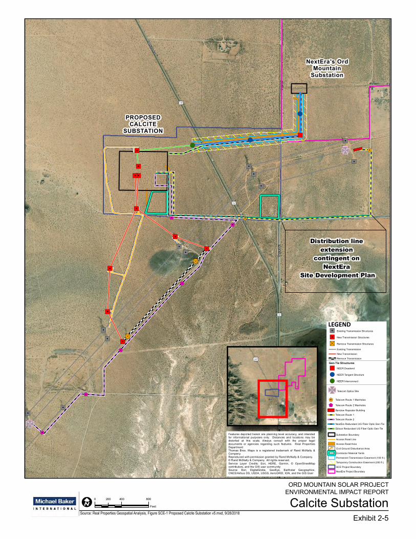
Calcite SubstationExhibit 2-5
ORD MOUNTAIN SOLAR PROJECT ENVIRONMENTAL IMPACT REPORT
$1
$1
$1
$1
$1
$1 $1$1
$1
"/
"/
"/"/ "/
"/ "/"/
"/ "/
"/
"/
"/"/
"/"/ "S
"/
"/
"/
"S
"/"/"/
"/
!(!(
!(
")
5
5
Distribution line extension
contingent on NextEra
Site Development Plan
PROPOSEDCALCITE
SUBSTATION
NextEra's OrdMountain
Substation
Path
: P:\P
RO
JEC
TS\M
PO_P
roje
cts\
Cal
cite
_Sub
stat
ion_
Jasp
er_C
SP\M
aps\
PEA
\Pro
ject
Des
crip
tion\
2016
_Dec
embe
r_U
pdat
e\Fi
gure
SC
E-1
Prop
osed
Cal
cite
Sub
stat
ion
v5.m
xd
Date: 9/28/2018File Name: Figure SCE-1 Proposed Calcite Substation v5.mxd
Version #: 5Created By: Gavin Jenkins
Real Properties Geospatial AnalysisProject Engineer: Saeed SadeghiProject Manager: Hamid Arshadi
I0 400 800200
Feet1 in = 542 feet
Features depicted herein are planning level accuracy, and intendedfor informational purposes only. Distances and locations may bedistorted at this scale. Always consult with the proper legaldocuments or agencies regarding such features. Real PropertiesDepartmentThomas Bros. Maps is a registered trademark of Rand McNally &Company.Reproduced with permission granted by Rand McNally & Company.© Rand McNally & Company. All rights reserved.Service Layer Credits: Esri, HERE, Garmin, © OpenStreetMapcontributors, and the GIS user communitySource: Esri, DigitalGlobe, GeoEye, Earthstar Geographics,CNES/Airbus DS, USDA, USGS, AeroGRID, IGN, and the GIS User
CALCITE SUBSTATIONFigure SCE-1: Proposed Calcite Substation"/ Existing Transmission Structures
"/ New Transmission Structures
"S Remove Transmission Structures
Existing Transmission
New Transmission
Remove Transmission
Gen-Tie Structures
") NEER Deadend
!( NEER Tangent Structure
!( NEER Interconnect
Gen-Tie AlignmentEdison Gen-Tie & OPGW
NextEra Gen-Tie & OPGW
OH Distribution
UG Distribution
5 Telecom Splice Site
$1 Telecom Route 1 Manholes
$1 Telecom Route 2 Manholes
Barstow Repeater Building
Telecom Route 1
Telecom Route 2
NextEra Redundant UG Fiber Optic Gen-Tie
Edison Redundant UG Fiber Optic Gen-Tie
Substation Boundary
Access Road Line
Access Road Area
Civil Ground Disturbance Area
Contractor Material Yards
Permanent Transmission Easement (100 ft.)
Temporary Construction Easement (200 ft.)
SCE Project Boundary
NextEra Project Boundary
$1
$1
$1
$1
$1
$1 $1$1
$1
"/
"/
"/"/ "/
"/ "/"/
"/ "/
"/
"/
"/"/
"/"/ "S
"/
"/
"/
"S
"/"/"/
"/
!(!(
!(
")
5
5
Distribution line extension
contingent on NextEra
Site Development Plan
PROPOSEDCALCITE
SUBSTATION
NextEra's OrdMountain
Substation
Path
: P:\P
RO
JEC
TS\M
PO_P
roje
cts\
Cal
cite
_Sub
stat
ion_
Jasp
er_C
SP\M
aps\
PEA
\Pro
ject
Des
crip
tion\
2016
_Dec
embe
r_U
pdat
e\Fi
gure
SC
E-1
Prop
osed
Cal
cite
Sub
stat
ion
v5.m
xd
Date: 9/28/2018File Name: Figure SCE-1 Proposed Calcite Substation v5.mxd
Version #: 5Created By: Gavin Jenkins
Real Properties Geospatial AnalysisProject Engineer: Saeed SadeghiProject Manager: Hamid Arshadi
I0 400 800200
Feet1 in = 542 feet
Features depicted herein are planning level accuracy, and intendedfor informational purposes only. Distances and locations may bedistorted at this scale. Always consult with the proper legaldocuments or agencies regarding such features. Real PropertiesDepartmentThomas Bros. Maps is a registered trademark of Rand McNally &Company.Reproduced with permission granted by Rand McNally & Company.© Rand McNally & Company. All rights reserved.Service Layer Credits: Esri, HERE, Garmin, © OpenStreetMapcontributors, and the GIS user communitySource: Esri, DigitalGlobe, GeoEye, Earthstar Geographics,CNES/Airbus DS, USDA, USGS, AeroGRID, IGN, and the GIS User
CALCITE SUBSTATIONFigure SCE-1: Proposed Calcite Substation"/ Existing Transmission Structures
"/ New Transmission Structures
"S Remove Transmission Structures
Existing Transmission
New Transmission
Remove Transmission
Gen-Tie Structures
") NEER Deadend
!( NEER Tangent Structure
!( NEER Interconnect
Gen-Tie AlignmentEdison Gen-Tie & OPGW
NextEra Gen-Tie & OPGW
OH Distribution
UG Distribution
5 Telecom Splice Site
$1 Telecom Route 1 Manholes
$1 Telecom Route 2 Manholes
Barstow Repeater Building
Telecom Route 1
Telecom Route 2
NextEra Redundant UG Fiber Optic Gen-Tie
Edison Redundant UG Fiber Optic Gen-Tie
Substation Boundary
Access Road Line
Access Road Area
Civil Ground Disturbance Area
Contractor Material Yards
Permanent Transmission Easement (100 ft.)
Temporary Construction Easement (200 ft.)
SCE Project Boundary
NextEra Project Boundary
LEGEND
Source: Real Properties Geospatial Analysis, Figure SCE-1 Proposed Calcite Substation v5.mxd, 9/28/2018

Ord Mountain Solar 2.0 Project Description Environmental Impact Report
San Bernardino County 2‐22
This page is intentionally blank

Ord Mountain Solar 2.0 Project Description Environmental Impact Report
San Bernardino County 2‐23
LOOP‐IN TRANSMISSION LINE
The proposed Calcite Substation would connect to the Lugo‐Pisgah No. 1 220‐kV transmission line
via a loop‐in that would modify the Lugo‐Pisgah No. 1 transmission line. That modification would
create two new line segments: the Calcite‐Lugo 220‐kV transmission line and the Calcite‐Pisgah
220‐kV transmission line. Each new transmission line segment entering the Calcite Substation
would be approximately 2,500 feet long.
The proposed routes for these new transmission lines would require crossing under SCE’s Eldorado‐
Lugo and Lugo‐Mohave with the safe clearance requirements of G0 95.
The new 220‐kV transmission lines would require approximately six transmission structures,
consisting of four single‐circuit structures and two double‐circuit structures. Four single‐circuit
structures with heights ranging from approximately 50 feet to approximately 100 feet would be
used to cross underneath the Eldorado‐Lugo 500‐kV and Lugo‐Mohave 500‐kV transmission lines.
The path would then continue north to two double‐circuit structures with approximate heights
between 130 and 160 feet. The conductor used would be 2B‐1590 kcmil “Lapwing” ACSR conductor
or similar.
Additionally, two existing 220‐kV lattice steel towers in the existing ROW would be removed. The
final combination of poles and towers will be determined during detailed engineering.
The six new structures would require a new ROW ranging between approximately 250 and 400 feet
wide (depending on structure types and line crossings) from SCE’s existing right‐of‐way to the
Calcite Substation property.
LOOP‐IN TRANSMISSION LINE ACCESS AND SPUR ROADS
Existing public roads and transmission line roads would be used as much as possible during
construction. However, the Calcite Substation Project would require new transmission line roads
to access the new 220‐kV transmission line segments and structure locations between the Calcite
Substation and the existing SCE right‐of‐way.
The graded road would have a minimum drivable width of between 14 and 22 feet with 2 feet of
shoulder on each side as required by the existing land terrain, but the road may be wider depending
on final engineering requirements and field conditions. The minimum center line turning radius
required along a curve is 50 feet (the minimum turning radius required to meet construction and
maintenance vehicle requirements), and berm and swale drainage improvements may be required
for erosion control along the road.

Ord Mountain Solar 2.0 Project Description Environmental Impact Report
San Bernardino County 2‐24
DISTRIBUTION SYSTEM FOR STATION LIGHT AND POWER
An extension of an existing 12‐kV distribution circuit would be required to provide temporary
power for construction and permanent station light and power for the Calcite Substation. The
Calcite Substation Project calls for extending the existing 12‐kV distribution circuit overhead
westward on Haynes Road for approximately 2,000 feet by installing approximately 12 wood poles.
The 12‐kV distribution circuit would then extend underground heading west along Haynes Road
under the existing SR 247 and transmission right‐of‐way and would then turn north along the
Calcite Substation driveway and into the substation. The total underground circuit extension length
would be approximately 1,700 feet, of which 1,400 feet is forecast to have surface disturbance.
These new facilities would also be used for installation of the required telecommunication fiber‐
optic cables into the Calcite Substation (described below under Telecommunication Facilities).
TELECOMMUNICATION FACILITIES
A telecommunication system would be required to provide monitoring and remote operation
capabilities of the electrical equipment at the Calcite Substation, transmission line protection, and
Remedial Action Scheme (RAS).
The SCE telecommunication facilities expected to be constructed as part of the Calcite Substation
project would include two approximately 1‐mile‐long fiber‐optic cables to the nearest splice points
on an optical ground wire that is expected to already be in place on the Lugo‐Mohave 500‐kV
Lugo‐Mohave transmission line by the time any work associated with the Calcite Substation Project
commences.1
The first proposed fiber‐optic cable would start from the Calcite Substation and would be
installed along the new 12‐kV distribution path previously described. The proposed line would
turn north along an unnamed dirt road for approximately 1,100 feet, attaching to existing wood
poles and arriving at the Barstow Repeater Communication Site (CS). The line would drop down
1 The optical ground wire (OPGW) is expected to be in place as a result of the anticipated completion of SCE’s Eldorado Lugo
Mohave (ELM) Series Capacitors project. The ELM Series Capacitors project is a distinct and independent project being separately undertaken by SCE that has independent utility from the Calcite Substation Project. Completion and operation of the ELM Series Capacitors project would include OPGW, which would be tapped to connect to the proposed Calcite Substation. Similarly, SCE also has another distinct and independent project with telecommunications equipment that, if constructed, would obviate the need to construct any other telecommunication facilities to support the Calcite Substation, namely, the Lugo‐Victorville 500‐kV Transmission Line Special Protection Scheme (SPS) Project. SCE has already submitted an application to the US Bureau of Land Management for authorization to complete the Lugo‐Victorville 500‐kV Transmission Line SPS Project. In light of the fact that both the ELM Series Capacitors Project and the Lugo‐Victorville 500‐kV Transmission Line SPS Project, currently planned by SCE, would be constructed and placed into operation prior to the operation of the Calcite Substation, SCE would not need to construct any further telecommunication facilities to support the Calcite Substation (other than the two 1‐mile taps described above).
Ord Mountain Solar 2.0 Project Description Environmental Impact Report
San Bernardino County 2‐25
in a new riser and continue underground for approximately 150 feet into an existing
communication room within the CS.
The second proposed fiber‐optic cable would start from the Calcite Substation and exit the
substation to the south. It would continue for approximately 400 feet in new underground conduit
and then turn east onto Haynes Road for approximately 1,200 feet. The conduit would turn
southwest on an existing access road for approximately 4,000 feet and then turn northwest to get
to tower M29‐T3 on the Lugo‐Mohave transmission line where the existing splice box is located.
This underground conduit route would be built exclusively for telecommunication use.
ANCILLARY FACILITIES
ACCESS ROAD
The Calcite Substation access road would be 24 feet wide and composed of asphalt concrete. The
access road would connect to SR 247 and would require the improvement of approximately 1,100
feet of the existing Haynes Road and the establishment of approximately 800 feet of new roadway.
Permanent land disturbance would be approximately 2 acres on the Calcite Substation property.
PERIMETER FENCE
The Calcite Substation would be an unattended collector station (no power transformation)
surrounded by a wall with a visible intrusion‐deterrent top guard and two gates.
LIGHTING
Low‐elevation (<14 foot) controlled security lighting would be installed within the substation. The
lighting would only be switched on when personnel enter the area (either motion‐sensor or manual
activation [switch]). All safety and emergency services signs would be lighted when the security
lighting is on. The lighting would be shielded so that the light is directed downward. Lighting would
be only in areas where it is required for safety, security, or operations. All lighting would be directed
on‐site and would include shielding as necessary to minimize illumination of the night sky or
potential impacts to surrounding viewers.
2.3 CONSTRUCTION
ORD MOUNTAIN SOLAR AND ENERGY STORAGE PROJECT
SCHEDULE
This proposed solar and energy storage project is anticipated to be built over an approximately 10‐
month time frame from the onset of perimeter fence installation through testing and

Ord Mountain Solar 2.0 Project Description Environmental Impact Report
San Bernardino County 2‐26
commissioning of the facility. It is anticipated that the work would be completed in 8‐ to 10‐hour
shifts, with a total of five shifts per week (Monday–Friday). Overtime and weekend work would
occur only as necessary to meet scheduled milestones or accelerate the schedule and would
comply with all applicable California labor laws. Primary construction activities and durations are
presented in Table 2‐2. The activities shown in the table would be overlapping in certain phases,
and all are expected to occur within the estimated 10‐month construction duration.
Table 2‐2:
Solar and Energy Storage Project Construction Duration, Equipment, and Workers by Activity
Activity Duration Equipment Pieces Daily Workers
Perimeter Fence
Installation 2 months
Skid Loader with Auger Attachment 1
Maximum = 250Average = 150
Pickup Truck 1
Flatbed Truck 1
Site Preparation and
Clearing/Grading 1.5 months
Water Truck – 3 Axles 3
Grader 2
Bulldozer 1
Scraper 1
10‐Ton Roller 1
Sheepsfoot Roller 1
Tractor (with Mower Attachment) 1
Demolition of Existing
Structures 2 weeks
Backhoe 1
Bulldozer 1
5‐Cubic‐Yard Dump Truck 4
Front‐End Loader 1
Underground Work
(Trenching) 3 months
Excavator 2
Sheepsfoot Roller 1
Water Truck – 3 Axles 1
5 kW Generator 1
Aussie Padder (Screening Machine) 1
4x4 Forklift 1

Ord Mountain Solar 2.0 Project Description Environmental Impact Report
San Bernardino County 2‐27
Activity Duration Equipment Pieces Daily Workers
System Installation 4 months
4x4 Forklift 8
Maximum = 250 Average = 150
Small Crane (80‐Ton) 1
All‐Terrain Vehicle 20
Pile Driver 4
Pickup Truck 4
5 kW Generator 2
Gen‐Tie Installation 1 month Line Truck (with Spool Trailer) 1
Boom Truck (with Bucket) 1
Energy Storage System 7 months
Foundation 1
Building Construction 1
Battery Installation 1
4x4 Forklift 1
Testing & Commissioning 3 months Pickup Truck 4
Site Cleanup & Restoration 1 month Grader 1
Skid Loader 1
CONSTRUCTION ACTIVITIES
Because the proposed solar and energy storage site is fairly level, grading is expected to be minor
in most instances. However, grading would occur throughout the site, especially for the
construction of roads and the inverter pads. This work would be accomplished with scrapers, motor
graders, water trucks, dozers, and compaction equipment. The PV modules would be off‐loaded
and installed using small cranes, boom trucks, forklifts, rubber‐tired loaders, rubber‐tired
backhoes, and other small to medium‐sized construction equipment as needed. Construction
equipment would be delivered to the site on “low‐bed” trucks unless the equipment can be driven
to the site (for example, the boom trucks). It is estimated that there would be approximately 35
pieces of construction equipment on‐site each month (see Table 2‐3).
Vegetation on the site would be modified only where necessary. Vegetation would be removed
where gravel roads would be constructed, where fill would be placed from grading operations,
where buildings are to be constructed, and where transmission pole and tracker foundations would
be installed (if necessary). At locations where transmission pole and tracker foundations would be
installed, minor cuts may be required where the foundations would be driven. Minor earthwork
would also occur to install aggregate base access roads and transmission line maintenance roads.
The surface of the roads would be at grade to allow any water to sheet flow across the site as it

Ord Mountain Solar 2.0 Project Description Environmental Impact Report
San Bernardino County 2‐28
currently does. Throughout the remainder of the developed area on the solar and energy storage
site, the vegetation root mass would generally be left in place to help maintain existing drainage
patterns on a micro level and to assist in erosion control. During construction, it is expected that
most of the vegetation would be cut, trimmed, or flattened as necessary, but otherwise left
undisturbed so that reestablishment is possible.
TRAFFIC
Peak daily construction employees would be approximately 250, with an average of 150 workers
daily. As shown in Table 2‐3, in addition to the 250 maximum daily workers traveling to the site,
there would be up to 19 truck trips per day during peak construction activity (the trenching and
system installation phases overlap). A total of up to 279 trips per day are anticipated during peak
construction activities, assuming a worst case whereby no carpooling occurs, though it is likely that
workers would carpool.
Table 2‐3:
Solar and Energy Storage Project Construction Estimated Truck Activity
Truck Type Average On‐Site Gross Weight (pounds) Trips/Day Duration
8,000‐Gallon Water Truck—will stay
on‐site 2 80,000 (loaded) 0 7 months
20‐Cubic‐Yard Dump/Bottom Dump
Truck 3 80,000 (loaded) 4+ 2 months
Pickup Truck 20 8,000 2 10 months
Pile Driver 4 15,000 1 4 months
Grader 2 54,000 1 3 months
Boom Truck with Bucket 1 42,000 1 2 months
Component Delivery Truck 1 42,000 19 2 months
Utility Line Service Truck 3 30,000 1 3 months
Delivery of material and supplies would reach the site via on‐road truck delivery via SR 247. Most
of the truck deliveries would be for the PV system installation, as well as any aggregate material
that may be required for road base. It is estimated that a total of up to 2,500 truck trips would be
required to complete the proposed solar and energy storage project, with the aggregate trucks
accounting for approximately 30 percent of this number. An average of 268 truck deliveries per
month (about 13 per workday) is estimated, with a peak number of 383 truck deliveries per month
(about 18 per workday) plus one other miscellaneous delivery, equating to a peak number of 19
truck trips per workday. These truck trips would be intentionally spread out throughout the

Ord Mountain Solar 2.0 Project Description Environmental Impact Report
San Bernardino County 2‐29
construction day to optimize construction efficiency as is practical by scheduling deliveries at
predetermined times.
The heaviest delivery loads to the site would also consist of the tracker structures, rock truck
deliveries, and the delivery of the generator step‐up (GSU). These loads would typically be limited
to total weight of 80,000 pounds, with a cargo load of approximately 25 tons or 50,000 pounds of
rock or tracker structures. The GSU could be up to 160,000 pounds. Typically, the rock would be
delivered in bottom dump trucks or transfer trucks with six axles, and the tracker structures would
be delivered on traditional flatbed trucks with a minimum of five axles. Low‐bed transport trucks
would transport the construction equipment to the site as needed. The size of the low‐bed truck
(number of axles for weight distribution) would depend on the equipment transported.
WATER USE
Water consumption during construction is estimated to be approximately 75 acre‐feet for dust
suppression and earthwork over an approximately 10‐month period. Panel rinsing is expected to
be conducted up to four times annually as dictated by performance testing and by weather and
site conditions. Water needed during construction as well as operational water for panel rinsing
would be provided by on‐site groundwater through an improved existing well or a new well
permitted and drilled (if necessary). An on‐site diesel generator may be used to power pumps for
well water use during construction. During construction, water would be pumped directly into
2,000‐ to 4,000‐gallon water trucks. Water may be stored in up to three temporary overhead water
storage tower/tanks of approximately 12,000 gallons (up to 16 feet tall) to facilitate the availability
of water for trucks and the expedient filling thereof. The existing wells on‐site that would not be
used would be capped in place in accordance with County requirements.
ON‐SITE ELECTRICAL DISTRIBUTION
Existing on‐site electrical power distribution lines that serve existing facilities, including well pumps,
would be removed to allow for the development of the solar and energy storage project. New
distribution lines would be needed to provide backup power to the solar and energy storage
facilities for lighting and communications purposes, as well as to the groundwater well pump(s).
CALCITE SUBSTATION
SCHEDULE
The Calcite Substation and associated transmission and telecommunication connections are
anticipated to be constructed over a period of approximately 10 months.
CONSTRUCTION ACTIVITIES

Ord Mountain Solar 2.0 Project Description Environmental Impact Report
San Bernardino County 2‐30
SCE anticipates a total of approximately 257 workers, with approximately 90 construction
personnel working on any given day. SCE anticipates that crews would work concurrently whenever
possible. However, the estimated deployment and number of crew members would be dependent
upon County permitting, material availability, and construction scheduling. For example,
installation of electrical equipment (such as the MEER, wiring, and circuit breaker) may occur while
the transmission line construction proceeds. Primary construction activities and durations are
presented in Table 2‐4.
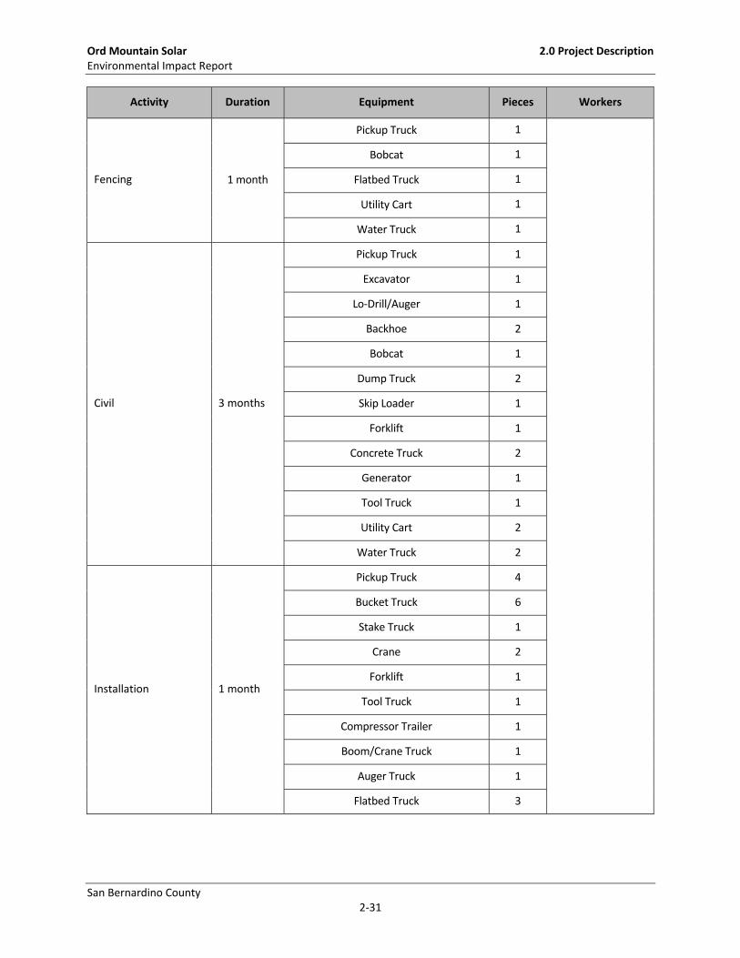
Table 2‐4:
Calcite Substation Project Construction Duration, Equipment, and Workers by Activity
Activity Duration Equipment Pieces Workers
Survey and Grading 2 months
Pickup Truck 8
Maximum = 257
Average = 90
Dozer 1
Loader 2
Scraper 2
Grader 1
Dump Truck 2
Backhoe 3
Tamper 1
Tool Truck 1
Utility Cart 2
Water Truck 7
Forklift 1
Ranger 1
Generator 1
Tracked Dozer 1
Motor Grader 1
Drum Compactor 1
Excavator 1
Lowboy Truck/Trailer 1
Ord Mountain Solar 2.0 Project Description Environmental Impact Report
San Bernardino County 2‐31
Activity Duration Equipment Pieces Workers
Fencing 1 month
Pickup Truck 1
Bobcat 1
Flatbed Truck 1
Utility Cart 1
Water Truck 1
Civil 3 months
Pickup Truck 1
Excavator 1
Lo‐Drill/Auger 1
Backhoe 2
Bobcat 1
Dump Truck 2
Skip Loader 1
Forklift 1
Concrete Truck 2
Generator 1
Tool Truck 1
Utility Cart 2
Water Truck 2
Installation 1 month
Pickup Truck 4
Bucket Truck 6
Stake Truck 1
Crane 2
Forklift 1
Tool Truck 1
Compressor Trailer 1
Boom/Crane Truck 1
Auger Truck 1
Flatbed Truck 3

Ord Mountain Solar 2.0 Project Description Environmental Impact Report
San Bernardino County 2‐32
Activity Duration Equipment Pieces Workers
Electrical 3 months
Pickup truck 2
Scissor Lift 1
Bucket Truck 2
Reach Manlift 1
Crane 1
Forklift 1
Generator 1
Utility Cart 2
Tool Truck 1
Wiring and Towers 3 months Pickup Truck 47
Bucket Truck 14
Utility Cart 1
Double Bucket Truck 3
Boom/Crane Truck 10
Puller 1
Static Truck/Tensioner 2
Dump/Stake Bed Truck 6
Compressor Trailer 7
R/T Crane (L) 5
R/T Crane (M) 3
Flatbed Truck 6
Backhoe/Front Loader 7
Excavator 1
Drill Rig 2
Concrete Truck 7
R/T Forklift 3
Crane 2
Sag Cat with Winches 4
Lowboy Truck/Trailer 4
Wire Truck/Trailer 2

Ord Mountain Solar 2.0 Project Description Environmental Impact Report
San Bernardino County 2‐33
Activity Duration Equipment Pieces Workers
Sock Line Puller 1
Bullwheel Puller 1
Spacing Cart 3
Hydraulic Rewind Puller 1
Excavation and Boring Equipment 1
Water Truck 4
Maintenance and
Testing 4 months
Pickup Truck 1
Test Truck 2
Paving 1.5 months
Pickup Truck 2
Stake Truck 1
Dump Truck 1
Asphalt Paver 1
Tractor 1
Paving Roller 2
Asphalt Curb Machine 1
Utility Cart 1
Telecommunications 2 months
Pickup Truck 10
Flatbed Truck 4
Bucket Truck 7
Splicing Lab 4
Backhoe/Front Loader 2
Water Truck 4
Concrete Truck 2
Site Cleanup &
Restoration 0.5 month
Pickup Truck 2
Backhoe/Front Loader 1
Motor Grader 1
Water Truck 1
Drum Compactor 1
Lowboy Truck/Trailer 1

Ord Mountain Solar 2.0 Project Description Environmental Impact Report
San Bernardino County 2‐34
Construction of the substation transmission lines, distribution lines, and telecommunications lines
would require the establishment of approximately 4 acres of staging yards within the Calcite
Substation property, outside of the substation site. An additional approximately 3.5 acres within
the Calcite Substation footprint will also be available for materials and equipment staging. The
yards would be used as a reporting location for workers, vehicle and equipment parking, and
materials storage. The yard would also have construction trailers for supervisory and clerical
personnel. The staging yard may be lit for staging and security.
TRAFFIC
Construction would be performed by SCE crews or SCE’s contract personnel, with crews ranging
from 4 to 28 personnel for any given activity. Multiple crews and activities may be ongoing on any
given day. SCE estimates approximately 257 workers would be required to construct the proposed
Calcite Substation project with up to 90 workers on‐site during peak days where activities overlap.
In addition to the 90 maximum daily workers traveling to the site, there would be up to 19 truck
trips per day during peak construction activities (trenching and system installation phases overlap).
A total of up to 109 trips per day are anticipated during peak construction activities. The estimated
number of persons and types of equipment required for each phase of transmission line
construction is provided in Table 2‐4.
WATER USE
The total anticipated water demand for construction of the proposed Calcite Substation project is
approximately 37 acre‐feet. No water is expected to be needed for operations, with nominal
amounts potentially necessary for maintenance in the event of repairs. Water would be sourced
either from the groundwater wells on the proposed solar and energy storage project site or from
the local water provider.
SUBSTATION
The Calcite Substation Property would be prepared by clearing existing vegetation and installing a
temporary chain‐link fence to surround the construction site. The property would be graded in
accordance with approved grading plans. The area to be enclosed by the proposed substation
perimeter wall would be graded to a slope that varies between one and two percent. To protect
the substation from flooding, and to keep the existing drainage patterns, drainage conveyances
would be constructed around the substation. These features would disturb an area approximately
35’ feet wide around the substation (approximately two acres) resulting in a total permanent
disturbance area of approximately 11 acres. For this property, there would be approximately 3,000
cubic of cut and 55,000 cubic yards of fill (51,000 cubic yards of on‐site and 4,000 cubic yards of
replacement fill). Final site grading and drainage would be subject to the conditions of the grading
permit obtained from the County of San Bernardino.

Ord Mountain Solar 2.0 Project Description Environmental Impact Report
San Bernardino County 2‐35
Additional temporary land disturbance (up to approximately 5 acres) within the proposed Calcite
Substation Property may be necessary for temporary equipment storage and material staging
areas. The Calcite Substation access road would be 24 feet wide and composed of asphalt concrete.
This road would connect to Highway 247 (Barstow Road) and would require the improvement of
approximately 1,100 feet of the existing Haynes Road and the establishment of approximately 800
feet of new road. Permanent land disturbance would be approximately 2 acres on the Calcite
Substation Property. Any permits needed for the access road would be acquired from the local
agencies.
LOOP‐IN TRANSMISSION STRUCTURES
The new structure pad locations and laydown/work areas would first be graded and/or cleared of
vegetation as required to provide a reasonably level and vegetation‐free surface for structure
installation. Erection of the structures may also require establishment of a permanent equipment
pad of approximately 50 feet by 50 feet adjacent to each applicable structure within the
laydown/work area used for structure assembly. The pad may be cleared of vegetation and/or
graded as necessary to provide a level surface for equipment operation. Typical structure
foundations for each LST would consist of four poured‐in‐place concrete footings; tubular steel
poles would require a single drilled poured‐in‐place concrete footing; and TSP H‐frames would
require two drilled poured‐in‐place concrete footings. Actual footing diameters and depths for
each of the structure foundations would depend on the soil conditions and topography at each
property and would be determined during final engineering.
Wire stringing activities would be in accordance with SCE’s common practices and are similar to
process methods detailed in IEEE Standard 524‐2003 (Guide to the Installation of Overhead
Transmission Line Conductors). Typical wire stringing activities may or may not include the use of
a helicopter.
The total land disturbance associated with the loop‐in line and the dead‐end structures for the
gen‐tie that SCE would install is estimated at approximately 23.3 acres. The majority of the
disturbance would be temporary (approximately 21.3 acres), and approximately 2.0 acres would
be permanently disturbed.
TELECOMMUNICATION FACILITIES
For the locations that require overhead construction, the permanent ground disturbance for each
pole installation would be approximately 4.9 square feet per pole and 0.1 square foot per pole
anchor. At some structure locations, vegetation may be removed and/or trimmed to accommodate
the installation of overhead and/or underground distribution facilities. For the locations that
require the construction of a trench or underground structure, excavation activities would
generally be done using a backhoe. The anticipated dimensions for the trench would be

Ord Mountain Solar 2.0 Project Description Environmental Impact Report
San Bernardino County 2‐36
approximately 24 inches wide by approximately 51 inches deep, resulting in approximately 0.38
acre of disturbance.
LAYDOWN AREAS AND ACCESS ROADS
Laydown areas may include the following existing SCE facilities:
Victorville Service Center, Hesperia Road, Victorville
Apple Valley Substation, Deep Creek Road, Apple Valley
Calcite Substation Property, Barstow Road (SR 247), Lucerne Valley
Barstow Service Center, Rimrock Road, Barstow
2.4 OPERATION
ORD MOUNTAIN SOLAR AND ENERGY STORAGE PROJECT
The proposed solar and energy project component would be unmanned, and no operation and
maintenance building would be constructed. Operations would be monitored remotely via the
SCADA system, and periodic inspections and maintenance activities would occur.
During operations, solar panel washing is expected to occur one to four times per year and general
labor (up to 10 individuals) may assist in the panel cleaning. Panel washing for a project of this size
would require 15 days to complete per wash cycle. Water consumption is expected to be around
0.28 gallons per square yard of panel, based on other similar operations. Given a 60 MW alternating
current plant, with four cycles per year, the annual water usage is expected to consume up to
approximately 6 acre‐feet of water. While the applicant only expects to wash the PV panels once
per year, the panels may need to be washed more frequently (up to four times per year) based on
site conditions. Conditions that may necessitate increased wash requirements include unusual
weather occurrences, forest fires, local air pollutants, and other similar conditions. Therefore, the
applicant is requesting the use of up to 6 acre‐feet of water per year for the explicit use of washing
panels. This amount is in addition to the amount of water necessary for operations, fire
suppression, and site landscape maintenance, which is a small amount of groundwater (i.e.,
approximately 0.6 acre‐feet) to be used for this purpose.
In the event that electrical power distribution cannot be delivered to the groundwater pump, a
generator would be located adjacent to the well pump to provide power. If groundwater proves
unsuitable for washing, water trucks would be used to deliver water from a local purveyor.

Ord Mountain Solar 2.0 Project Description Environmental Impact Report
San Bernardino County 2‐37
CALCITE SUBSTATION
The proposed Calcite Substation would be unstaffed, and electrical equipment within the
substation would be remotely monitored and controlled by an automated system from SCE’s Lugo
Substation Switching Center. Operations and Maintenance (O&M) activities are necessary to
ensure reliable service, as well as the safety of utility workers and the general public, as mandated
by the CPUC. SCE facilities are subject to Federal Energy Regulatory Commission jurisdiction. SCE
transmission facilities are under the operational control of the California Independent System
Operator (CAISO). SCE personnel would typically visit for electrical switching and routine
maintenance purposes. Routine maintenance would include equipment testing, monitoring, and
repair.
Operation of the new telecommunication facilities would commence following the completion of
project construction. Inspection and maintenance activities would occur at least once per year or
on an as‐needed basis.
2.5 DECOMMISSIONING
ORD MOUNTAIN SOLAR AND ENERGY STORAGE PROJECT
The PV system and energy storage system (including structure) would be recycled when the solar
and energy storage project’s life is over. Most parts of the proposed system are recyclable. Panels
typically consist of silicon, glass, and a metal frame. Tracking systems (not counting the motors and
control systems) typically consist of aluminum and steel. Batteries include lithium‐ion, which
degrades but can be recycled and/or repurposed. Site structures would include steel or wood and
concrete. All these materials can be recycled. Concrete from deconstruction is to be recycled. Local
recyclers are available. Metal and scrap equipment and parts that do not have free‐flowing oil may
be sent for salvage.
Fuel, hydraulic fluids, and oils would be transferred directly to a tanker truck from the respective
tanks and vessels. Storage tanks/vessels would be rinsed and transferred to trucks. Other items
that are not feasible to remove at the point of generation, such as smaller containers of lubricants,
paints, thinners, solvents, cleaners, batteries, and sealants, would be kept in a locked utility building
with integral secondary containment that meets Certified Unified Program Agencies (CUPA) and
Resource Conservation and Recovery Act (RCRA) requirements for hazardous waste storage until
its removal for proper disposal and recycling. It is anticipated that all oils and batteries would be
recycled at an appropriate facility.
Site personnel involved in handling these materials would be trained to in proper handling
techniques. Containers used to store hazardous materials would be inspected regularly for any

Ord Mountain Solar 2.0 Project Description Environmental Impact Report
San Bernardino County 2‐38
signs of failure or leakage. Transportation of the removed hazardous materials would comply with
regulations for transporting hazardous materials, including those set by the US Department of
Transportation (DOT), US Environmental Protection Agency (EPA), California Department of Toxic
Substances Control (DTSC), California Highway Patrol (CHP), and California State Fire Marshal.
Upon removal of the proposed solar and energy storage project components, the site would be left
as disturbed dirt generally consistent with the existing (pre‐development) conditions, subject to a
closure plan in accordance with San Bernardino Development Code Section 84.29.60.
CALCITE SUBSTATION
The Calcite Substation would not be decommissioned during decommissioning of the solar and
energy storage portion of the project.