Embed Size (px)
Citation preview

.Pu\
Ä.Pu\ä
安装指导 ZH
ENMounting Instructions
g200 W050 ... W180 | 50 Nm ... 180 Nm蜗轮蜗杆减速机 L 蜗轮蜗杆减速机带三相交流电机Worm gearbox / Worm gearbox with three-phase ACmotor

请操作前仔细阅读操作指导书>按照安全指导说明进行操作K
Please read these instructions before you start working!
Follow the enclosed safety instructions.

目录 i
ZH
3Lenze •MA 12.0020 • 1.0
N 文档内容 Q
NKN 文档历史 Q
NKO 规则运用 Q
NKP 专用名词 Q
NKQ 注释定义 R
O 安全指导 S
OKN 驱动元件常规安全指导 S
P 产品描述 T
PKN 重要注释 T
PKO 识别 TPKOKN 铭牌 U
PKP 运输重量 U
Q 机械安装 V
QKN 重要注释 V
QKO 准备 VQKOKN 减速机E带通气孔F V
QKP 安装 NMQKPKN 带实心轴减速机的安装 NMQKPKO 减速机E带空心轴和键槽F附件 NM
R 电气安装 NO
S 调试与运行 NP
SKN 重要注释 NP
SKO 启动前 NP
SKP 运行中 NQ
T 保养 NR
TKN 重要注释 NR
TKO 维护操作 NR
TKP 维修 NR
TKQ 清除 NR
U 故障检修与故障消除 NS

文档内容文档历史1
ZH
4 Lenze • MA 12.0020 • 1.0
0001 文档内容目录• 本文档用于减速机或减速机相关设备的安全相关操作指导,其中包含务必遵守的安全指导说明。• 在进行减速机操作时,须确保始终携有本文档,且须遵守本文档所规定的相关信息和注释。• 本文档必须始终保持完整,且清晰可读。目标组本文档针对依据 fb` SMPSQ 具有资质的专业人员。具有资质的专业人员是指有资格执行产品安放、安装、调试和操作工作的人员。 技巧>有关 iÉåòÉ 产品的信息和辅助设备请查询以下网址的下载区
ÜííéWLLïïïKiÉåòÉKÅçã
1.1 文档历史材料编号 版本 描述.Pu\ 1.0 02LOMNR TD29 小批量生产系列初版1.2 规则运用该文档应用下列条款来区分不同的信息类型:信息类型 标记 示例L注释数字拼写小数分隔符 点 一般使用小数点。例如:NOPQKRS图标页面参考 参阅另一页面以查看其他相关信息例如W NS Z 参见页面 NS文档参考 参阅另一文档以查看其他相关信息例如W bahñññZ见文档bahñññ通配符 选配用通配符,选型数据1.3 专用名词术语 在如下文本,用于减速机 ÖOMM系列减速机驱动系统 驱动系统带ÖOMM减速机和其他iÉåòÉ驱动元件

文档内容注释定义 1
ZH
5Lenze • MA 12.0020 • 1.0
1.4 注释定义为了指明危险和重要信息,将在该文档中使用下列象形图和信号词:安全指导安全指导结构: 危险>(标记危险的类型和严重程度)提示文本(描述危险状态并提示防范危险的方法)象形图和信号词 含义 危险>
危险电压存在人身伤害危险提示有直接威胁的危险,如不采取相应措施会导致死亡或严重伤害。 危险>
一般危险源存在人身伤害危险提示有直接威胁的危险,如不采取相应措施会导致死亡或严重伤害。 停止> 财产损失危险提示可能的危险,如不采取相应措施可能导致财产损失。使用指导象形图和信号词 含义 注释> 重要提示,确保无故障运行 技巧> 便于搬运的有用提示 参考其他文档

安全指导驱动元件常规安全指导2
ZH
6 Lenze • MA 12.0020 • 1.0
2 安全指导2.1 驱动元件常规安全指导 危险>如果忽视下列基本安全措施,可能导致严重的人员受伤以及财产损失:• 存储于干燥、少震少风环境;如有可能,请使用制造商的包装存储。
– 防尘防不良影响保护。– 依据技术参数,样本,注意遵守气候条件。
• iÉåòÉ 驱动与自动化组件KKK
KKK 仅用于预设目的。KKK 损坏时切勿使用。KKK 不可进行任何技术改动。KKK 未完成组装前切勿进行任何操作。KKK 无防护罩或防护装置时切勿进行任何操作。KKK 根据其防护等级,在运行期间或运行后均可能存在带电、移动或旋转部件。表面也可能是热的。KKK 切勿在震动强烈时使用。KKK 切勿在工厂或驱动系统的频率范围下使用。
• 请注意在所附的相关文件中预先规定的所有条件。这是保证安全和无故障运行并达到规定产品性能的前提条件。• 只能由具备资质的专业技术人员来操作iÉåòÉ驱动与自动化组件。根据fb` SMPSQ或`bkbib` ea PUQI 这些人员应 KKK
KKK 熟悉产品的安装、组装、调试和操作,KKK 具备所在岗位的职业资质I
KKK 熟悉并可恰当引用使用地的相关意外防护章程、指令和适用的法律法规。

产品描述重要注释 3
ZH
7Lenze • MA 12.0020 • 1.0
3 产品描述3.1 重要注释• 最重要的技术数据均在铭牌中标示(结构文本结构及内容参见 U)。• 产品样本包含更多技术数据。3.2 识别安装位置E^JcF与系统模块位置ENJSF
端子盒W OI PI QI R
1. ÖOMMJtMRM不带通风2. ÖOMMJtMVM和ÖOMMJtNUM标准安装位置
^L`带通风3. 其他情况,请在下单时注明是否需要通风。4. 减速机供货时通风孔已堵上。用户在完成安装后需自行使用所供的通风阀替换螺塞。

产品描述运输重量铭牌3
ZH
8 Lenze • MA 12.0020 • 1.0
3.2.1 铭牌k版本 举例mçëK 目录N 制造商L产地O 减速机和电机型号P 生产年份L周数Q 安装位置L系统模块的位置R 额定转矩额定转速L额定频率S 润滑油量和润滑油类型T 减速比U 物料编号L序列号V 条形码NM 订单编号NN 运行系数(在YNKM时显示FNO 其他客户信息NP 允许环境温度范围 E在适用情况下F
3.3 运输重量减速机类型L尺寸 电机机座号MSP MTN MUM MVM
ÖOMMJtMRM Y NM Y NMÖOMMJtMVM YNR YNRÖOMMJtNUM YOM YOR表 1 重量EâÖF

机械安装重要注释减速机E带通气孔F
4
ZH
9Lenze • MA 12.0020 • 1.0
4 机械安装4.1 重要注释• 使用负荷设备进行运输!• 运输前
– 检查所有组件是否已安全装上,– 紧固所有运输辅件(带孔螺栓或支承板)。 危险>由负载倾倒或降落造成的危害!
• 起重机和负载搬运设备的有效负荷须至少与负载重量相匹配。详见重量样本。• 负载应进行紧固以确保其不会倾倒或降落。• 请勿在悬挂负载下面停留!
4.2 准备 注释>彻底除去输出轴和法兰面上的防腐剂。4.2.1 减速机E带通气孔F
停止>禁止将减速机置于排气阀上!更多详情,见 TK 注释>随主机配备的通气阀必须根据对应安装位置进行安装。 ( 7)K

机械安装安装带实心轴减速机的安装4
ZH
10 Lenze • MA 12.0020 • 1.0
4.3 安装4.3.1 带实心轴减速机的安装• 使用丝杆把传动部件移到输出轴上。 停止>冲击振动会损坏滚动轴承。4.3.2 减速机E带空心轴和键槽F附件1. 将减速机拖至待驱动机轴上:
– 在轴和空心轴孔上涂上所供的组装膏ENF 。GT-GNG-GKR-011.iso GT-GNG-GKR-011_a.iso图 1 使用组装膏来防止接触腐蚀(包含在供货范围内)
停止>仅通过空心轴而非减速机外壳使力。2. 轴向紧固减速机W
– 空心轴具备卡环槽,用于轴向紧固。用于紧固轴的部件不包含在供货范围内。K12.0611辅助工具 E推荐规格F
ÇeT ÇO ÅTNUOM
jS Q
ORPM
jNM RS
PR jNO T表 2 规格 xããz

机械安装安装减速机E带空心轴和键槽F附件 4
ZH
11Lenze • MA 12.0020 • 1.0
拆卸1. 撤回空心轴里的轴向减速机锁。2. 使用适当的辅助工具将减速机从电机轴上移除L提取 EOF。
K12.0611图 2 使用辅助工具拆卸带空心轴减速机辅助工具 E推荐规格F
ÇeT ÅU ÅVORPM
NM P
PR NO P表 3 规格 xããz
注释>借助于伞齿轮减速机,空心轴中间设置可任意转动,如这里的内径高于MKNãã> 须注意确保机轴足够长。减速机类型L尺寸 äN ãáå ä ã~ñK
ÖOMMJtMRM UR NMMÖOMMJtMVM NMR NOMÖOMMJtNUM NOT NQP表 4 尺寸EããF

电气安装5
ZH
12 Lenze • MA 12.0020 • 1.0
5 电气安装 危险>非专业人员不得擅自进行电气接线>
电机电气连接,请参阅电机相关文档!

调试与运行重要注释 6
ZH
13Lenze • MA 12.0020 • 1.0
6 调试与运行6.1 重要注释 停止>必须由专业人员调试驱动器!• 进行任何操作前,请先采取安全措施W
– 从电源上断开设备,确保驱动系统已停止,并避免任何设备的运行。6.2 启动前请检查W
• 驱动器功能 J 设备功能分配• 驱动轴旋转方向ÖOMMJt 一级• 驱动器看起来未受损?• 机械安装是否正确?• 电气连接是否正确?• 所有旋转部件和可能发热的表面是否已进行防触保护?• 对于带通气的减速机W
– 安装完成后将螺塞替换成所供的通风阀?

调试与运行运行中6
ZH
14 Lenze • MA 12.0020 • 1.0
6.3 运行中操作过程中,请定期检查驱动器,且尤其要注意:• 与常规操作相比存在的变更之处,比如
– 异常噪音,更强的振动或温度升高,– 泄漏I
– 松开固定用元件,– 电缆状况I
– 油操作温度不应持续超过UMø`。• 如发生故障W
– 关闭驱动器,– 检查故障检修列表。如故障仍无法修复,请联系iÉåòÉ售后服务处。
维护重要注释 7
ZH
15Lenze • MA 12.0020 • 1.0
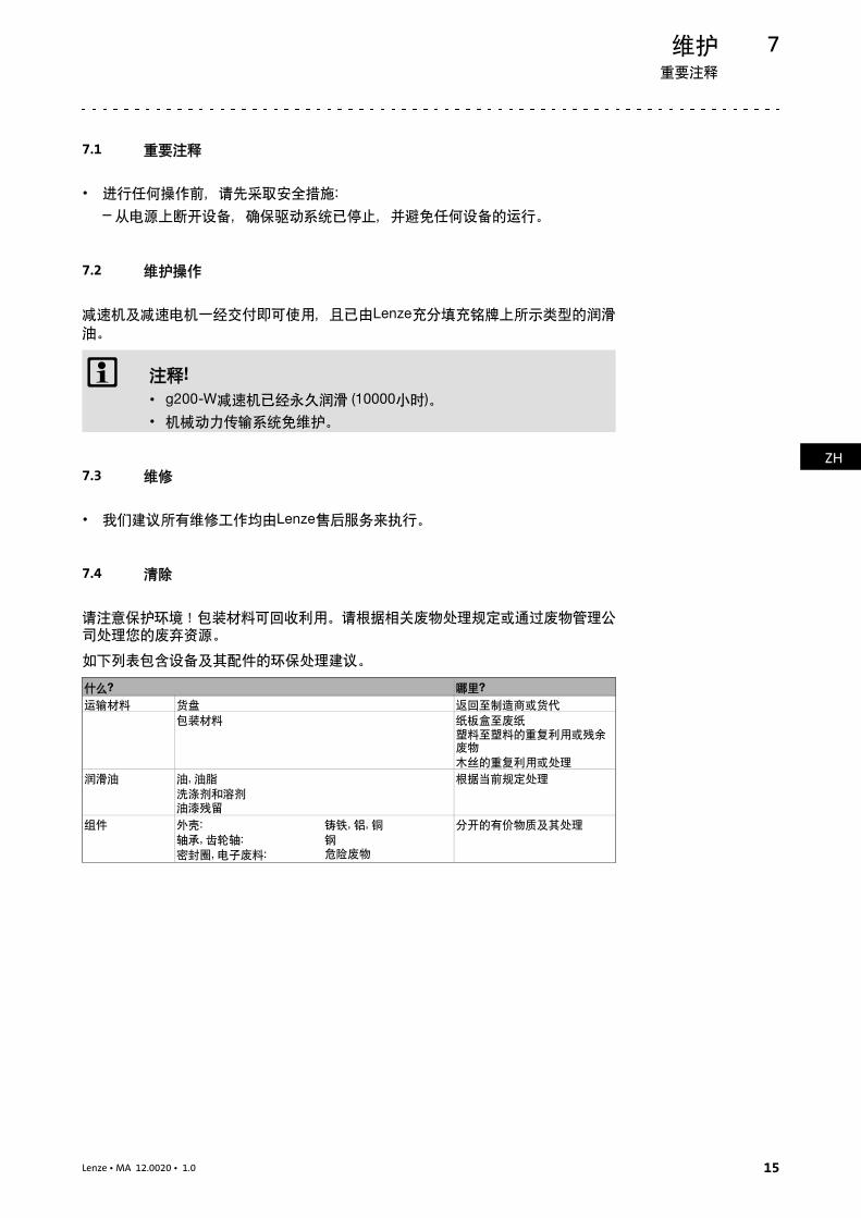
7 保养7.1 重要注释• 进行任何操作前,请先采取安全措施W
– 从电源上断开设备,确保驱动系统已停止,并避免任何设备的运行。7.2 维护操作减速机及减速电机一经交付即可使用,且已由iÉåòÉ充分填充铭牌上所示类型的润滑油。 注释>
• ÖOMMJt减速机已经永久润滑 ENMMMM小时F。• 机械动力传输系统免维护。
7.3 维修• 我们建议所有维修工作均由iÉåòÉ售后服务来执行。7.4 清除请注意保护环境!包装材料可回收利用。请根据相关废物处理规定或通过废物管理公司处理您的废弃资源。如下列表包含设备及其配件的环保处理建议。什么\ 哪里\运输材料 货盘 返回至制造商或货代包装材料 纸板盒至废纸塑料至塑料的重复利用或残余废物木丝的重复利用或处理润滑油 油I 油脂洗涤剂和溶剂油漆残留 根据当前规定处理组件 外壳W轴承I 齿轮轴W密封圈I 电子废料W
铸铁I 铝I 铜钢危险废物 分开的有价物质及其处理
故障检修与故障消除8
ZH
16 Lenze • MA 12.0020 • 1.0
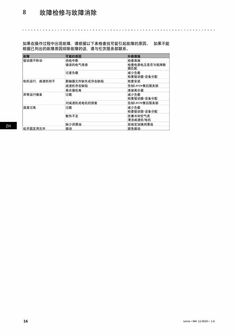
8 故障检修与故障消除如果在操作过程中出现故障,请根据以下表格查找可能引起故障的原因。 如果不能根据已列出的故障原因排除故障的话,请与伦茨服务部联系。故障 可能的原因 补救措施驱动器不转动 供电中断 检查连接错误的电气连接 检查电源电压是否与铭牌数据匹配过度负载 减少负载检查驱动器J设备分配电机运行,减速机则不 联轴器元件缺失或存在缺陷 检查安装减速机存在缺陷 告知iÉåòÉ售后服务部离合器松离 连接离合器异常运行噪音 过载 减少负载检查驱动器J设备分配对减速机或电机的损害 告知iÉåòÉ售后服务部温度过高 过载 减少负载检查驱动器J设备分配散热不足 改善冷却空气流清洁减速机L电机缺少润滑油 按规定加满润滑油松开固定用元件 振动 避免振动

Contents i
EN
17Lenze •MA 12.0020 • 1.0
1 About this documentation 18
1.1 Document history 18
1.2 Conventions used 18
1.3 Terminology used 19
1.4 Notes used 19
2 Safety instructions 20
2.1 General safety instructions for drive components 20
3 Product description 21
3.1 Important notes 21
3.2 Identification 21
3.2.1 Nameplate 22
3.3 Transport weights 22
4 Mechanical installation 23
4.1 Important notes 23
4.2 Preparation 23
4.2.1 Gearboxes with breathers 23
4.3 Mounting 244.3.1 Mounting gearboxes with solid shafts 24
4.3.2 Attachment of gearboxes with hollow shafts and keyway 24
5 Electrical installation 26
6 Commissioning and operation 27
6.1 Important notes 27
6.2 Before switching on 27
6.3 During operation 28
7 Maintenance 29
7.1 Important notes 29
7.2 Maintenance operations 29
7.3 Repair 29
7.4 Disposal 29
8 Troubleshooting and fault elimination 30
About this documentationDocument history
1
EN
18 Lenze • MA 12.0020 • 1.0
0Fig. 0Tab. 01 About this documentation
Contents
• This documentation serves for safety-relevant operations on and with thegearboxes. It contains safety instructions which must be observed.
• All personnel working on and with the gearboxes must have the documentationavailable during the work and observe the information and notes relevant forthem.
• The documentation must always be complete and in a perfectly readable state.
Target group
This documentation is directed at qualified skilled personnel according to IEC 60364.
Qualifiedskilledpersonnelarepersonswhohavetherequiredqualificationstocarryoutall activities involved in installing, mounting, commissioning, and operating theproduct.
Tip!Information and tools concerning the Lenze products can be found in thedownload area under
www.lenze.com
1.1 Document history
Material number Version Description.Pu\ 1.0 02/2015 TD29 First edition for the pilot series
1.2 Conventions used
This documentation uses the following conventions to distinguish different types ofinformation:
Type of information Identification Examples/notesSpelling of numbersDecimal separator Point In general, the decimal point is used.
For instance: 1234.56IconsPage reference Reference to another page with
additional informationFor instance: 16 = see page 16
Documentation reference Reference to another documentationwith additional informationFor example: EDKxxx = seedocumentation EDKxxx
Wildcard Wildcard for options, selection data

About this documentationTerminology used
1
EN
19Lenze • MA 12.0020 • 1.0
1.3 Terminology used
Term In the following text used forGearboxes Gearboxes of the g200 product family
Drive system Drive systems with g200 gearboxes and other Lenze drivecomponents
1.4 Notes used
The following pictographs and signalwords are used in this documentation to indicatedangers and important information:
Safety instructions
Structure of safety instructions:
Danger!(characterises the type and severity of danger)
Note(describes the danger and gives information about how to preventdangerous situations)
Pictograph and signal word Meaning
Danger!
Danger of personal injury through dangerous electricalvoltage.Reference to an imminent danger that may result in deathor serious personal injury if the corresponding measures arenot taken.
Danger!
Danger of personal injury through a general source ofdanger.Reference to an imminent danger that may result in deathor serious personal injury if the corresponding measures arenot taken.
Stop!Danger of property damage.Reference to a possible danger that may result in propertydamage if the corresponding measures are not taken.
Application notes
Pictograph and signal word Meaning
Note! Important note to ensure troublefree operation
Tip! Useful tip for simple handling
Reference to another documentation

Safety instructionsGeneral safety instructions for drive components
2
EN
20 Lenze • MA 12.0020 • 1.0
2 Safety instructions
2.1 General safety instructions for drive components
Danger!Disregarding the following basic safety measures may lead to severepersonal injury and damage to material assets!
• Store in dry, low-vibration environment without aggressive atmosphere; ifpossible in the manufacturer’s packaging.
– Protect against dust and impacts.
– Observe the climatic conditions according to the technical data, catalogue.
• Lenze drive and automation components ...
... must only be used as intended.
... must never be commissioned despite noticeable damage.
... must never be technically changed.
... must never be commissioned in an incompletely mounted state.
... must never be operated without the required covers.
... may have live, moving or rotary parts during and after operation - correspondingto their type of protection. Surfaces may be hot.
... must not be operated with large vibrations.
... must not be operated in the frequency range of a plant or the drive system.
• All specifications of the corresponding enclosed documentation must beobserved.
This is vital for safe and trouble-free operation and for achieving the specifiedproduct features.
• Only qualified skilled personnel are permitted to work with or on Lenze drive andautomation components.
According to IEC 60364 or CENELEC HD 384, these are persons ...
... whoare familiarwith the installation, assembly, commissioningandoperationofthe product,
... possess the appropriate qualifications for their work,
... and are acquainted with and can apply all the accident prevent regulations,directives and laws applicable at the place of use.

Product descriptionImportant notes
3
EN
21Lenze • MA 12.0020 • 1.0
3 Product description
3.1 Important notes
• The most important technical data are indicated on the nameplate (structure andcontents 22).
• The product catalogues contain further technical data.
3.2 Identification
Mounting position (A-F) and position of systemmodules (1-6)
Terminal box: 2, 3, 4, 5
1. g200-W050 without ventilation
2. g200-W090 and g200-W180 standard mounting position
A/C with ventilation
3. Any other situation please specify when order if need ventilation
4. The gearboxes are supplied with ventilation holes plugged. The user is required toreplace the plugs with the supplied ventilation valves after installation.

Product descriptionTransport weightsNameplate
3
EN
22 Lenze • MA 12.0020 • 1.0
3.2.1 Nameplate
N version Example
Pos. Contents1 Manufacturer / production location2 Gearbox and motor type3 Year / week of manufacture4 Mounting position / position of the system blocks5 Rated torque
Rated speed/rated frequency6 Lubricant amount / type of lubricant7 Ratio8 Material number / serial number9 Bar code10 Order number11 Operating factor (indicated when <1.0)12 Additional customer data13 Permissible ambient temperature range (where applicable)
3.3 Transport weights
Gearbox type/size
Motor frame size
063 071 080 090g200-W050 <10 <10g200-W090 <15 <15g200-W180 <20 <25
Tab. 1 Weights in kg

Mechanical installationImportant notes
Gearboxes with breathers
4
EN
23Lenze • MA 12.0020 • 1.0
4 Mechanical installation
4.1 Important notes
• Use load carrying equipment for transport!• Before the transport
– check that all components are safely mounted,– fasten all transport aids (eye bolts or support plates).
Danger!Danger due to toppling or falling loads!• The payload of the hoists and load handling devices must at least
correspond to the weight of the load.
• The load must be secured in such a way that it cannot topple or falldown.
• Do not stay under a pending load!
4.2 Preparation
Note!Thoroughly remove anticorrosion agents from output shafts and flangefaces.
4.2.1 Gearboxes with breathers
Stop!Do not place gearbox onto breather valve!
For details see 21.
Note!Loosely enclosed vent valves must be mounted in accordance with themounting position ( 21).

Mechanical installationMountingMounting gearboxes with solid shafts
4
EN
24 Lenze • MA 12.0020 • 1.0
4.3 Mounting
4.3.1 Mounting gearboxes with solid shafts
• Draw the transmission elements onto the output shaft only by using thecentering thread.
Stop!Shocks and blows to the shafts damage the roller bearings.
4.3.2 Attachment of gearboxes with hollow shafts and keyway
1. Draw the gearbox with hollow shaft onto the machine shaft to be driven:
– Apply the supplied assembly paste (Fig. 1) on the shaft and in the hollow shaftbore.
GT-GNG-GKR-011.iso GT-GNG-GKR-011_a.iso
Fig. 1 Application of assembly paste against fretting corrosion (included in the scope of supply)
Stop!Take up forces only via the hollow shaft, and not via gearbox housing.
2. Secure the gearbox axially:
– The hollow shaft has snap ring grooves for axial securing. Parts used to fix theshaft are not included in the scope of supply.
K12.0611
Auxiliary tool (recommended dimensions)
dH7 d2 c71820
M6 4
2530
M10 56
35 M12 7
Tab. 2 Dimensions in [mm]

Mechanical installationMounting
Attachment of gearboxes with hollow shafts and keyway
4
EN
25Lenze • MA 12.0020 • 1.0
Dismounting
1. Undo axial gearbox locking in the hollow shaft.
2. Remove/extract the gearbox from the motor shaft using an appropriate auxiliarytool (Fig. 2).
K12.0611
Fig. 2 Disassembly of gearboxes with hollow shaft, with auxiliary tool
Auxiliary tool (recommended dimensions)
dH7 c8 c92530
10 3
35 12 3
Tab. 3 Dimensions in [mm]
Note!With the bevel gearbox, the hollow shafts are turned free in the middleof the hollow shaft, i.e. the bore diameter is 0.1 mm higher here! Asufficient length of the machine shaft must be observed.
Gearbox type/size l1 min l max.g200-W050 85 100g200-W090 105 120g200-W180 127 143
Tab. 4 Dimensions in mm

Electrical installation5
EN
26 Lenze • MA 12.0020 • 1.0
5 Electrical installation
Danger!Electrical connections must only be carried out by skilled personnel!
Read the motor documentation for a correct electrical connection of themotor!

Commissioning and operationImportant notes
6
EN
27Lenze • MA 12.0020 • 1.0
6 Commissioning and operation
6.1 Important notes
Stop!The drive may only be commissioned by skilled personnel!
• Take safety measures prior to any operation:
– Disconnect the machine from the mains, ensure standstill of the drive systemand avoid any machine movement.
6.2 Before switching on
Please check:
• Drive function - machine function assignment
• The direction of rotation of the drive shaft
g200-W 1-stage
• Does the drive appear undamaged?
• Is the mechanical fixing o.k.?
• Is the electrical connection correct?
• Are all rotating parts and surfaces that may become hot protected againstcontact?
• For gearboxes with breathing:
– Has the plug been replaced with the supplied ventilation valve afterinstallation?

Commissioning and operationDuring operation
6
EN
28 Lenze • MA 12.0020 • 1.0
6.3 During operation
During operation, check the drive periodically and take special care of:
• changes compared to normal operation, like
– unusual noise, stronger vibrations or increased temperatures,
– leakages,
– loose fixing elements,
– the condition of the electrical cables,
– the operating temperature of the oil shall not exceed 80 °C continuously.
• In the event of faults:
– shut down the drive,
– check the troubleshooting table.
If the fault cannot be remedied, please contact the Lenze customer service.

MaintenanceImportant notes
7
EN
29Lenze • MA 12.0020 • 1.0
7 Maintenance
7.1 Important notes
• Take safety measures prior to any operation:
– Disconnect the machine from the mains, ensure standstill of the drive systemand avoid any machine movement.
7.2 Maintenance operations
Gearboxes and gearedmotors are ready to use on delivery and filled by Lenzewith thelubricant type and lubricant quantity indicated on the nameplate.
Note!• The g200-W gearbox is lubricated for life (10,000 hours).
• The mechanical power transmission system is maintenance-free.
7.3 Repair
• We recommend having all repairs carried out by the Lenze customer service.
7.4 Disposal
Protect the environment! Packingmaterial can be recycled. Dispose of your separatedresources according to the waste disposal regulations or via a waste managementcompany.
The following table provides recommendations for an environmentally friendlydisposal of the machine and its components.
What? Where?Transportmaterial
Pallets Return to the manufacturer orforwarder
Packaging material Cardboard box to waste paperPlastics to plastics recycling orresidual wasteReuse or dispose of wood wool
Lubricants Oil, greaseDetergents and solventsPaint residues
Dispose according to currentregulations
Components Housing:
Bearings, gear wheel shafts:Seals, electronic scrap:
Cast iron, aluminium,copperSteelHazardous waste
Separate valuable substancesand dispose

Troubleshooting and fault elimination8
EN
30 Lenze • MA 12.0020 • 1.0
8 Troubleshooting and fault elimination
If anymalfunctions shouldoccurduringoperationof thedrive system,please check thepossible causesusing the following table. If the fault cannotbeeliminatedbyoneof thelisted measures, please contact the Lenze Service.
Fault Possible cause RemedyDrive is not running Voltage supply interrupted Check connection
Faulty electrical connection Check that supply voltagematches nameplate data
Excessive load Reduce loadCheck drive-machineassignment
Motor is running, butgearbox is not running
Coupling components are missing ordefective
Check mounting
Gearbox is defective Inform Lenze ServiceClutch disengaged Engage the clutch
Unusual running noises Overload Reduce loadCheck drive-machineassignment
Damage to the gearbox or motor Inform Lenze ServiceExcessive temperature Overload Reduce load
Check drive-machineassignment
Inadequate heat dissipation Improve cooling air flowClean gearbox / motor
Lack of lubricant Top up lubricant according toregulations
Loose fixing elements Vibrations Avoid vibrations


© 02/2015 | MA 12.0020 |.Pu\ | 1.0 | TD29
Lenze Drive Systems (Shanghai) Co., Ltd2989 Jiangshan Road, Lingang New CityShanghaiChina 201306
+86 21 3828 0451
+86 21 3828 0450
www.lenze.com
Lenze Drive Systems (Shanghai) Co., Ltd2989 Jiangshan Road, Lingang New CityShanghaiChina 201306
+86 21 3828 0451
+86 21 3828 0450
10 9 8 7 6 5 4 3 2 1