Embed Size (px)
Citation preview

InverterInverter i510-Cabinet0.37 kW ... 15 kW0.5 hp ... 20 hp
InverterInverter i510 Cabinet0.37 kW ... 15 kW0.5 hp ... 20 hp
Montage- und Einschaltanleitung | Mounting and switch-on instructions


InhaltÜber dieses Dokument 6
Dokumentbeschreibung 6Weiterführende Dokumente 6
Schreibweisen und Konventionen 7Sicherheitshinweise 8
Grundlegende Sicherheitshinweise 8Bestimmungsgemäße Verwendung 9Handhabung 9Restgefahren 10
Produktinformation 11Identifizierung der Produkte 11Ausstattung 12
Mechanische Installation 16Wichtige Hinweise 16Vorbereitung 17Abmessungen 19
Inhalt
3

Elektrische Installation 31Wichtige Hinweise 31Anschluss nach UL 32Netzanschluss 36
1-phasiger Netzanschluss 230/240 V 36Anschlusspläne 36Klemmendaten 38Absicherungsdaten 38
3-phasiger Netzanschluss 230/240 V 39Anschlusspläne 39Klemmendaten 41Absicherungsdaten 41
3-phasiger Netzanschluss 230/240 V "Light Duty" 41Anschlusspläne 41Klemmendaten 41Absicherungsdaten 41
3-phasiger Netzanschluss 400 V 42Anschlusspläne 42Klemmendaten 43Absicherungsdaten 43
3-phasiger Netzanschluss 400 V "Light Duty" 44Anschlusspläne 44Klemmendaten 44Absicherungsdaten 44
3-phasiger Netzanschluss 480 V 45Anschlusspläne 45Klemmendaten 45Absicherungsdaten 46
3-phasiger Netzanschluss 480 V "Light Duty" 46Anschlusspläne 46Klemmendaten 46Absicherungsdaten 46
Anschluss an das IT-Netz 47Steueranschlüsse 48Netzwerke 49
CANopen/Modbus 49Inbetriebnahme 50
Wichtige Hinweise 50Erstes Einschalten und Funktionstest 51
Inhalt
4

Technische Daten 53Normen und Einsatzbedingungen 53
Konformitäten/Approbationen 53Personenschutz und Geräteschutz 53Angaben zur EMV 53Motoranschluss 54Umweltbedingungen 54Netzbedingungen 54
1-phasiger Netzanschluss 230/240 V 55Bemessungsdaten 55
3-phasiger Netzanschluss 230/240 V 57Bemessungsdaten 57
3-phasiger Netzanschluss 230/240 V "Light Duty" 59Bemessungsdaten 59
3-phasiger Netzanschluss 400 V 60Bemessungsdaten 60
3-phasiger Netzanschluss 400 V "Light Duty" 62Bemessungsdaten 62
3-phasiger Netzanschluss 480 V 63Bemessungsdaten 63
3-phasiger Netzanschluss 480 V "Light Duty" 65Bemessungsdaten 65
Inhalt
5

Über dieses Dokument
WARNUNG!Lesen Sie diese Dokumentation sorgfältig, bevor Sie mit den Arbeiten beginnen.▶ Beachten Sie die Sicherheitshinweise!
Dokumentbeschreibung
Weiterführende DokumenteFür bestimmte Aufgaben stehen Informationen in anderen Formen zur Verfügung.Form Inhalt/ThemenEngineering Tools Zur InbetriebnahmeAKB-Artikel Application Knowledge Base mit technischen Zusatzinformationen für AnwenderCAD-Daten Exporte in verschiedenen FormatenEPLAN Makros Projektierung, Dokumentation und Verwaltung von Projekten für P8.
• Datenbezug über Lenze oder EPLAN Data Portal
Informationen und Hilfsmittel rund um die Lenze-Produkte finden Sie im Internet:http://www.lenze.com à Downloads
Über dieses DokumentDokumentbeschreibungWeiterführende Dokumente
6

Schreibweisen und Konventionen
Zur Unterscheidung verschiedener Arten von Informationen werden in diesem Dokument Konventionen ver-wendet.Zahlenschreibweise Dezimaltrennzeichen Punkt Es wird generell der Dezimalpunkt verwendet.
Beispiel: 1 234.56Warnhinweise UL-Warnhinweise UL Werden in englischer und französischer Sprache verwendet. UR-Warnhinweise URTextauszeichnung Engineering Tools » « Software
Beispiel: »Engineer«, »EASY Starter«Symbole Seitenverweis ¶ Verweis auf eine andere Seite mit zusätzlichen Informationen
Beispiel: ¶ 16 = siehe Seite 16 Dokumentationsverweis , Verweis auf eine andere Dokumentation mit zusätzlichen Informationen
Beispiel: , EDKxxx = siehe Dokumentation EDKxxx
Gestaltung der Sicherheitshinweise
GEFAHR!Kennzeichnet eine außergewöhnlich große Gefahrensituation. Wird dieser Hinweis nicht beachtet, kommt eszu schweren irreversiblen Verletzungen oder zum Tod.
WARNUNG!Kennzeichnet eine außergewöhnlich große Gefahrensituation. Wird dieser Hinweis nicht beachtet, kann eszu schweren irreversiblen oder tödlichen Verletzungen kommen.
VORSICHT!Kennzeichnet eine Gefahrensituation. Wird dieser Hinweis nicht beachtet, kann es zu leichten oder mittlerenVerletzungen kommen.
HINWEISKennzeichnet Sachgefahren. Wird dieser Hinweis nicht beachtet, kann es zu Sachschäden kommen.
Über dieses DokumentSchreibweisen und Konventionen
7

SicherheitshinweiseWenn Sie die folgenden grundlegenden Sicherheitsmaßnahmen und Sicherheitshinweise missachten, kanndies zu schweren Personenschäden und Sachschäden führen!Beachten Sie die Vorgaben der beiliegenden und zugehörigen Dokumentation. Dies ist Voraussetzung füreinen sicheren und störungsfreien Betrieb, sowie für das Erreichen der angegebenen Produkteigenschaften.Beachten Sie die spezifischen Sicherheitshinweise in den anderen Abschnitten!
GEFAHR!Elektrische SpannungMögliche Folge: Tod oder schwere Verletzungen▶ Alle Arbeiten am Inverter nur im spannungslosen Zustand durchführen.▶ Inverter bis 45 kW: Nach dem Abschalten der Netzspannung mindestens 3 min warten, bevor Sie mit den
Arbeiten beginnen.▶ Inverter ab 55 kW: Nach dem Abschalten der Netzspannung mindestens 10 min warten, bevor Sie mit den
Arbeiten beginnen.
Grundlegende Sicherheitshinweise
GEFAHR!Gefährliche elektrische SpannungTod oder schwere Verletzungen durch Stromschlag.▶ Alle Arbeiten am Gerät nur im spannungslosen Zustand durchführen.▶ Nach dem Abschalten der Netzspannung die Hinweisschilder auf dem Produkt beachten.
PersonalNur qualifiziertes Fachpersonal darf Arbeiten mit dem Produkt ausführen. IEC 60364 bzw. CENELEC HD 384definieren die Qualifikation dieser Personen:• Sie sind mit Aufstellung, Montage, Inbetriebsetzung und Betrieb des Produkts vertraut.• Sie verfügen über die entsprechenden Qualifikationen für ihre Tätigkeit.• Sie kennen alle am Einsatzort geltenden Unfallverhütungsvorschriften, Richtlinien und Gesetze und kön-
nen diese anwenden.
VerfahrenstechnikDie dargestellten verfahrenstechnischen Hinweise und Schaltungsausschnitte sind Vorschläge, deren Über-tragbarkeit auf die jeweilige Anwendung überprüft werden muss. Für die Eignung der angegebenen Verfah-ren und Schaltungsvorschläge übernimmt der Hersteller keine Gewähr.Geräteschutz• Die maximale Prüfspannung bei Isolationsprüfungen zwischen 24-V-Steuerpotential und PE darf 110 V DC
nicht überschreiten (EN 61800−5−1).
SicherheitshinweiseGrundlegende Sicherheitshinweise
8

Bestimmungsgemäße Verwendung
• Das Produkt darf nur unter den in dieser Dokumentation vorgeschriebenen Einsatzbedingungen betrie-ben werden.
• Das Produkt erfüllt die Schutzanforderungen der 2014/35/EU: Niederspannungsrichtlinie.• Das Produkt ist keine Maschine im Sinne der 2006/42/EU: Maschinenrichtlinie.• Die Inbetriebnahme oder die Aufnahme des bestimmungsgemäßen Betriebs einer Maschine mit dem Pro-
dukt ist solange untersagt, bis festgestellt wurde, dass die Maschine den Bestimmungen der EU-Richtlinie2006/42/EU: Maschinenrichtlinie entspricht; EN 60204−1 beachten.
• Die Inbetriebnahme oder die Aufnahme des bestimmungsgemäßen Betriebs ist nur bei Einhaltung derEMV-Richtlinie 2014/30/EU erlaubt.
• Die harmonisierte Norm EN 61800−5−1 wird angewendet.• Das Produkt ist kein Haushaltsgerät, sondern als Komponente ausschließlich bestimmt für die Weiterver-
wendung zur gewerblichen Nutzung bzw. professionellen Nutzung im Sinne der EN 61000−3−2.• Das Produkt kann entsprechend der technischen Daten eingesetzt werden, wenn Antriebssysteme Kate-
gorien gemäß EN 61800−3 einhalten müssen.Im Wohnbereich kann das Produkt EMV-Störungen verursachen. Der Betreiber ist für die Durchführungvon Entstörmaßnahmen verantwortlich.
• Das Produkt darf nur mit Motoren betrieben werden, die für den Betrieb mit Invertern geeignet sind.- L-force-Motoren von Lenze erfüllen diese Anforderung.- Ausnahme: Motoren m240 sind ausschließlich für den Netzbetrieb bestimmt.
Handhabung
• Das Produkt niemals trotz erkennbarer Schäden in Betrieb nehmen.• Das Produkt niemals technisch verändern.• Das Produkt niemals unvollständig montiert in Betrieb nehmen.• Das Produkt niemals ohne erforderliche Abdeckungen betreiben.• Alle elektrischen Verbindungen nur im spannungslosen Zustand herstellen, trennen und verändern!
SicherheitshinweiseHandhabung
9

Restgefahren
Auch wenn gegebene Hinweise beachtet und Schutzmaßnahmen angewendet werden, können Restrisikenverbleiben.Die genannten Restgefahren muss der Anwender in der Risikobeurteilung für seine Maschine/Anlage berück-sichtigen.Nichtbeachtung kann zu schweren Personenschäden und Sachschäden führen!
ProduktBeachten Sie die Warnschilder auf dem Produkt!Symbol Beschreibung
Elektrostatisch gefährdete Bauelemente:Vor Arbeiten am Produkt muss sich das Personal von elektrostatischer Aufladung befreien!
Gefährliche elektrische Spannung:Vor Arbeiten am Produkt überprüfen, ob alle Leistungsanschlüsse spannungslos sind!Die Leistungsanschlüsse führen nach Netzausschalten für die bei dem Symbol angegebene Zeit gefährlicheelektrische Spannung!Hoher Ableitstrom:Festinstallation und PE−Anschluss nach EN 61800−5−1 oder EN 60204−1 ausführen!
Heiße Oberfläche:Persönliche Schutzausrüstung verwenden oder Abkühlung abwarten!
MotorschutzBei bestimmten Einstellungen der Inverter kann der angeschlossene Motor überhitzt werden.• Z. B. durch längeren Betrieb eigenbelüfteter Motoren bei kleinen Drehzahlen.• Z. B. durch längeren Betrieb der Gleichstrombremse.
Schutz der Maschine/AnlageAntriebe können gefährliche Überdrehzahlen erreichen.• Z. B. durch Einstellung hoher Ausgangsfrequenzen bei dafür ungeeigneten Motoren und Maschinen.• Die Inverter bieten keinen Schutz gegen solche Betriebsbedingungen. Setzen Sie dafür zusätzliche externe
Komponenten ein.
Schütze in der Motorleitung nur bei gesperrtem Inverter schalten.• Das Schalten bei freigegebenem Inverter ist nur zulässig, wenn keine Überwachungen ansprechen.
MotorBei Kurzschluss zweier Leistungstransistoren kann am Motor eine Restbewegung von bis zu 180°/Polpaarzahlauftreten! (Z. B. 4-poliger Motor: Restbewegung max. 180°/2 = 90°).Schutzart - Personenschutz und Geräteschutz• Angaben gelten für den betriebsfertig montierten Zustand.• Angaben gelten nicht im Anschlussbereich der Klemmen.- Bei nicht belegten Klemmen besteht nur geringer Berührungsschutz.- Klemmen für große Leitungsquerschnitte haben geringere Schutzklassen, z. B. ab 15 kW nur IP10.
SicherheitshinweiseRestgefahren
10

ProduktinformationIdentifizierung der Produkte
In Tabellen werden die ersten 9 Stellen des jeweiligen Produktcodes verwendet, um die Produkte zu identifi-zieren:Produktcode I 5 1 A E □□□ □ 1 0 □ □ □ □□□□Produktart Inverter I Produktfamilie i500 5 Produkt i510 1 Produktgeneration Generation 1 A
Generation 2 B Montageart Schaltschrankmontage E Bemessungsleistung [W](Beispiele)
0.25 kW 125 0.55 kW 155 2.2 kW 222
Netzspannung und Anschlussart 1/N/PE AC 230/240 V B 1/N/PE AC 230/240 V2/N/PE AC 230/240 V D
3/PE AC 230/240 V C 3/PE AC 400 V3/PE AC 480 V
F
Motoranschlüsse Einzelachse 1 Integrierte funktionale Sicherheit Ohne 0 Schutzart IP20 0
IP20, verlackt V Funkentstörung Ohne 0
Funkentstörfilter integriert 1 Ausführungsvarianten Globale Ausführung 50 Hz 0
Lokale Ausführung 60 Hz 1 Basic-I/O ohne Netzwerk 000SBasic-I/O mit CANopen/Modbus 001S
Beispiel:Produktcode BedeutungI51AE215F10010001S Inverter i510 Cabinet, 1.5 kW, 3-phasig, 400 V/480 V
IP20, Funkentstörfilter integriert, 50-Hz-VarianteBasic-I/O mit CANopen/Modbus-Netzwerk
ProduktinformationIdentifizierung der Produkte
11

Ausstattung
Beispiel für 0.25 kW ... 4 kW
Schirmauflage
PE-Anschluss Netzanschluss/DC-Bus
Relaisausgang
Netzwerk
Schnittstelle
Steuerklemmen
Schirmauflage SteueranschlüsseIT-Schraube
IT-Schraube ab 0.55 kW
Status- s Inverter LED
Motoranschluss
Option
Option
Basic I/O
Diagnosemodul
Anschluss Bremswiderstand
X100
X16
X3
X105
X216
X9
SpeichermodulX20Status- s NetzwerkLED
Umschalter CANopen/Modbus
ProduktinformationAusstattung
12

Beispiel für 0.25 kW ... 2.2 kWPE-Anschluss Netzanschluss X100
Relaisausgang X9
Netzwerk X216
Schni! stelle X16
Steuerklemmen X3
Schirmauflage
IT-Schraube
Schirmauflage
IT-Schraube
Status-LEDs Inverter
Motoranschluss X105
Speichermodul X20CANopen/Modbus (Op!on)
CANopen/Modbus
Steueranschlüsse
Basic I/O
Diagnosemodul
Status-LEDs Netzwerk
ab 0,55 kW
Umschalter
CANopen/Modbus
ProduktinformationAusstattung
13

Beispiel für 5.5 kW
PE-Anschluss
Netzanschluss
RelaisausgangNetzwerk
Schnittstelle
SteuerklemmenSchirmauflage
IT-Schraube
Schirmauflage
Status- s Inverter LED
Motoranschluss
Speichermodul
CANopen/Modbus (Option)
CANopen/Modbus
Steueranschlüsse Basic I/O
Diagnosemodul
Status- s NetzwerkLED
Umschalter CANopen/Modbus
X9X216
X105
X16
X100
X20
X3
ProduktinformationAusstattung
14

Beispiel für 7.5 kW ... 11 kWPE-Anschluss Netzanschluss
Relaisausgang
Netzwerk
Schnittstelle
SteuerklemmenSchirmauflage
IT-Schraube
Schirmauflage
Status- s Inverter LED
Motoranschluss
Speichermodul
CANopen/Modbus (Option)
CANopen/Modbus
SteueranschlüsseBasic I/O
Diagnosemodul
Status- s NetzwerkLED
Umschalter CANopen/Modbus
X9
X216
X105
X16
X100
X20
X3
ProduktinformationAusstattung
15

Mechanische InstallationWichtige Hinweise
HINWEIS▶ UL marking▶ Modular construction - A complete drive consists of a power unit series no. I5D in combination with a
control unit series no. I5C only.▶ Marquage UL▶ Conception modulaire – Le système d’entraînement complet comprend un module d’alimentation de
série I5D, impérativement associé à une unité de commande de série I5C.
Mechanische InstallationWichtige Hinweise
16

Vorbereitung
Montage Schirmauflageblech für Motorleitung 0.25 kW bis 4 kW (optionales Zubehör)
3.4 Nm(30 lb-in)
❶ ❷
M5
❸
Das Schirmauflageblech wird zusammen mit dem Inverter auf der Montageplatte verschraubt.
Montage Schirmauflageblech für Motorleitung 5.5 kW (optionales Zubehör)
2 Nm(17.7 lb-in)
❶ ❷
M4x12
❸
Mechanische InstallationVorbereitung
17

Montage Schirmauflageblech für Motorleitung 7.5 kW bis 11 kW (optionales Zubehör)
2 Nm(17.7 lb-in)
❶ ❷
M4x12
❸
Mechanische InstallationVorbereitung
18

Abmessungen
0.25 kW ... 0.37 kWDie Abmessungen in mm gelten für:0.25 kW I51AE125B I51AE125D 0.37 kW I51AE137B I51AE137D I51AE137F
Mechanische InstallationAbmessungen
19

0.33 hp ... 0.5 hpDie Abmessungen in inch gelten für:0.33 hp I51AE125B I51AE125D 0.5 hp I51AE137B I51AE137D I51AE137F
Mechanische InstallationAbmessungen
20

0.55 kW ... 0.75 kWDie Abmessungen in mm gelten für:0.55 kW I51AE155B I51AE155D I51AE155F0.75 kW I51AE175B I51AE175D I51AE175F
Mechanische InstallationAbmessungen
21

0.75 hp ... 1 hpDie Abmessungen in inch gelten für:0.75 hp I51AE155B I51AE155D I51AE155F1 hp I51AE175B I51AE175D I51AE175F
Mechanische InstallationAbmessungen
22

1.1 kW ... 4 kWDie Abmessungen in mm gelten für:1.1 kW I51AE211B I51AE211D I51AE211F1.5 kW I51AE215B I51AE215D I51AE215F2.2 kW I51AE222B I51AE222D I51AE222F3 kW I51BE230F4 kW I51BE240F
Mechanische InstallationAbmessungen
23

1.5 hp ... 5.5 hpDie Abmessungen in inch gelten für:1.5 hp I51AE211B I51AE211D I51AE211F2 hp I51AE215B I51AE215D I51AE215F3 hp I51AE222B I51AE222D I51AE222F4 hp I51BE230F5.5 hp I51BE240F
Mechanische InstallationAbmessungen
24

1.1 kW ... 2.2 kWDie Abmessungen in mm gelten für:1.1 kW I51AE211B I51AE211D I51AE211F1.5 kW I51AE215B I51AE215D I51AE215F2.2 kW I51AE222B I51AE222D I51AE222F
Mechanische InstallationAbmessungen
25

1.5 hp ... 3 hpDie Abmessungen in inch gelten für:1.5 hp I51AE211B I51AE211D I51AE211F2 hp I51AE215B I51AE215D I51AE215F3 hp I51AE222B I51AE222D I51AE222F
Mechanische InstallationAbmessungen
26

5.5 kWDie Abmessungen in mm gelten für:5.5 kW I51AE255C I51AE255F
Mechanische InstallationAbmessungen
27

7.5 hpDie Abmessungen in inch gelten für:7.5 hp I51AE255C I51AE255F
Mechanische InstallationAbmessungen
28

7.5 kW ... 11 kWDie Abmessungen in mm gelten für:7.5 kW I51AE275F11 kW I51AE311F
Mechanische InstallationAbmessungen
29

10 hp ... 15 hpDie Abmessungen in inch gelten für:10 hp I51AE275F15 hp I51AE311F
Mechanische InstallationAbmessungen
30

Elektrische InstallationWichtige Hinweise
GEFAHR!Elektrische SpannungMögliche Folge: Tod oder schwere Verletzungen▶ Alle Arbeiten am Inverter nur im spannungslosen Zustand durchführen.▶ Inverter bis 45 kW: Nach dem Abschalten der Netzspannung mindestens 3 min warten, bevor Sie mit den
Arbeiten beginnen.▶ Inverter ab 55 kW: Nach dem Abschalten der Netzspannung mindestens 10 min warten, bevor Sie mit den
Arbeiten beginnen.
GEFAHR!Gefährliche elektrische SpannungDer Ableitstrom gegen Erde (PE) ist > 3.5 mA AC bzw. > 10 mA DC.Mögliche Folgen: Tod oder schwere Verletzungen beim Berühren des Gerätes im Fehlerfall.▶ Die in der EN 61800−5−1 oder EN 60204−1 geforderten Maßnahmen umsetzen. Insbesondere:▶ Festinstallation▶ PE-Anschluss normgerecht ausführen (PE-Leiterdurchmesser ≥ 10 mm2 oder PE-Leiter doppelt ausführen)
Elektrische InstallationWichtige Hinweise
31
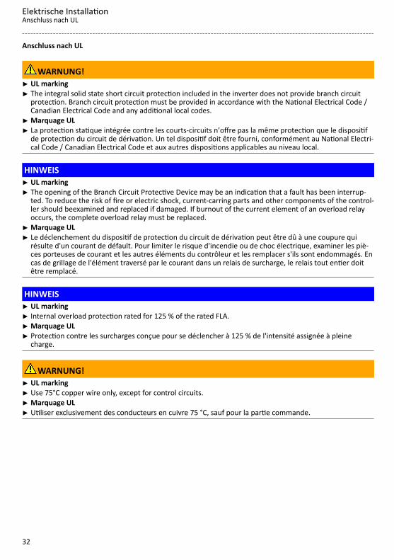
Anschluss nach UL
WARNUNG!▶ UL marking▶ The integral solid state short circuit protection included in the inverter does not provide branch circuit
protection. Branch circuit protection must be provided in accordance with the National Electrical Code /Canadian Electrical Code and any additional local codes.
▶ Marquage UL▶ La protection statique intégrée contre les courts-circuits n’offre pas la même protection que le dispositif
de protection du circuit de dérivation. Un tel dispositif doit être fourni, conformément au National Electri-cal Code / Canadian Electrical Code et aux autres dispositions applicables au niveau local.
HINWEIS▶ UL marking▶ The opening of the Branch Circuit Protective Device may be an indication that a fault has been interrup-
ted. To reduce the risk of fire or electric shock, current-carring parts and other components of the control-ler should beexamined and replaced if damaged. If burnout of the current element of an overload relayoccurs, the complete overload relay must be replaced.
▶ Marquage UL▶ Le déclenchement du dispositif de protection du circuit de dérivation peut être dû à une coupure qui
résulte d'un courant de défault. Pour limiter le risque d'incendie ou de choc électrique, examiner les piè-ces porteuses de courant et les autres éléments du contrôleur et les remplacer s'ils sont endommagés. Encas de grillage de l'élément traversé par le courant dans un relais de surcharge, le relais tout entier doitêtre remplacé.
HINWEIS▶ UL marking▶ Internal overload protection rated for 125 % of the rated FLA.▶ Marquage UL▶ Protection contre les surcharges conçue pour se déclencher à 125 % de l'intensité assignée à pleine
charge.
WARNUNG!▶ UL marking▶ Use 75°C copper wire only, except for control circuits.▶ Marquage UL▶ Utiliser exclusivement des conducteurs en cuivre 75 °C, sauf pour la partie commande.
Elektrische InstallationAnschluss nach UL
32

WARNUNG!▶ UL marking▶ Suitable for motor group installation or use on a circuit capable of delivering not more than the rms sym-
metrical amperes (SCCR) of the drive at its rated voltage.▶ Approved fusing is specified in SCCR tables below.▶ Marquage UL▶ Convient pour l'utilisation sur une installation avec un groupe de moteurs ou sur un circuit capable de
fournir au maximum une valeur de courant efficace symétrique en ampères à la tension assignée de l'ap-pareil.
▶ Les dispositifs de protection adaptés sont spécifiés dans les SCCR tableaux suivants.
Elektrische InstallationAnschluss nach UL
33

Branch Circuit Protection (BCP) with Short Circuit Current Ratings (SCCR) with Standard Fuses. (Tested perUL61800-5-1, reference UL file E132659)These devices are suitable for motor group installation when used with Standard Fuses. For single motorinstallation, if the fuse value indicated is higher than 400% of the motor current (FLA), the fuse value has tobe calculated. If the value of the fuse is below two standard ratings, the nearest standard ratings less thanthe calculated value shall apply.
Inverter Standard Fuses (UL248)
Mains kW hp SCCR Max. ratedcurrent Class
120 V, 1-ph 0.25 0.33 5 kA 15 A CC120 V, 1-ph 0.37 0.50 5 kA 15 A CC120 V, 1-ph 0.75 1.00 5 kA 30 A CC, J, T120 V, 1-ph 1.10 1.50 5 kA 30 A CC, J, T230 V, 1-ph 0.25 0.33 65 kA 15 A CC230 V, 1-ph 0.37 0.50 65 kA 15 A CC230 V, 1-ph 0.55 0.75 65 kA 15 A CC230 V, 1-ph 0.75 1.00 65 kA 15 A CC230 V, 1-ph 1.10 1.50 65 kA 30 A CC, J, T230 V, 1-ph 1.50 2.00 65 kA 30 A CC, J, T230 V, 1-ph 2.20 3.00 65 kA 30 A CC, J, T
230 V, 1/3-ph 0.25 0.33 65 kA 15 A CC230 V, 1/3-ph 0.37 0.50 65 kA 15 A CC230 V, 1/3-ph 0.55 0.75 65 kA 15 A CC230 V, 1/3-ph 0.75 1.00 65 kA 15 A CC230 V, 1/3-ph 1.10 1.50 65 kA 30 A CC, J, T230 V, 1/3-ph 1.50 2.00 65 kA 30 A CC, J, T230 V, 1/3-ph 2.20 3.00 65 kA 30 A CC, J, T230 V, 3-ph 4.00 5.00 100 kA 40 A J, T230 V, 3-ph 5.50 7.50 100 kA 40 A J, T480 V, 3-ph 0.37 0.50 65 kA 15 A CC480 V, 3-ph 0.55 0.75 65 kA 15 A CC480 V, 3-ph 0.75 1.00 65 kA 15 A CC480 V, 3-ph 1.1 1.5 65 kA 15 A CC480 V, 3-ph 1.5 2.0 65 kA 15 A CC480 V, 3-ph 2.2 3.0 65 kA 15 A CC480 V, 3-ph 3.0 4.0 65 kA 25 A CC, J, T480 V, 3-ph 4.0 5.0 65 kA 25 A CC, J, T480 V, 3-ph 5.5 7.5 65 kA 25 A CC, J, T480 V, 3-ph 7.5 10.0 65 kA 40 A J, T480 V, 3-ph 11.0 15.0 65 kA 40 A J, T480 V, 3-ph 15.0 20.0 100 kA 70 A J, T480 V, 3-ph 18.5 25.0 100 kA 70 A J, T480 V, 3-ph 22 30 100 kA 70 A J, T
480 V, 3-ph * 30 40 22 kA 125 A J, T480 V, 3-ph * 37 50 22 kA 125 A J, T480 V, 3-ph * 45 60 22 kA 125 A J, T480 V, 3-ph * 55 75 22 kA 200 A J, T480 V, 3-ph * 75 100 22 kA 200 A J, T480 V, 3-ph * 90 125 22 kA 300 A J, T480 V, 3-ph * 110 150 22 kA 300 A J, T
* Mains choke required
Elektrische InstallationAnschluss nach UL
34
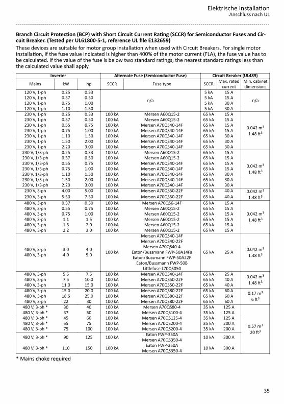
Branch Circuit Protection (BCP) with Short Circuit Current Rating (SCCR) for Semiconductor Fuses and Cir-cuit Breaker. (Tested per UL61800-5-1, reference UL file E132659)These devices are suitable for motor group installation when used with Circuit Breakers. For single motorinstallation, if the fuse value indicated is higher than 400% of the motor current (FLA), the fuse value has tobe calculated. If the value of the fuse is below two standard ratings, the nearest standard ratings less thanthe calculated value shall apply.
Inverter Alternate Fuse (Semiconductor Fuse) Circuit Breaker (UL489)
Mains kW hp SCCR Fuse type SCCR Max. ratedcurrent
Min. cabinetdimensions
120 V, 1-ph 0.25 0.33
n/a
5 kA 15 A
n/a120 V, 1-ph 0.37 0.50 5 kA 15 A120 V, 1-ph 0.75 1.00 5 kA 30 A120 V, 1-ph 1.10 1.50 5 kA 30 A230 V, 1-ph 0.25 0.33 100 kA Mersen A60Q15-2 65 kA 15 A
0.042 m3
1.48 ft3
230 V, 1-ph 0.37 0.50 100 kA Mersen A60Q15-2 65 kA 15 A230 V, 1-ph 0.55 0.75 100 kA Mersen A70QS40-14F 65 kA 15 A230 V, 1-ph 0.75 1.00 100 kA Mersen A70QS40-14F 65 kA 15 A230 V, 1-ph 1.10 1.50 100 kA Mersen A70QS40-14F 65 kA 30 A230 V, 1-ph 1.50 2.00 100 kA Mersen A70QS40-14F 65 kA 30 A230 V, 1-ph 2.20 3.00 100 kA Mersen A70QS40-14F 65 kA 30 A
230 V, 1/3-ph 0.25 0.33 100 kA Mersen A60Q15-2 65 kA 15 A
0.042 m3
1.48 ft3
230 V, 1/3-ph 0.37 0.50 100 kA Mersen A60Q15-2 65 kA 15 A230 V, 1/3-ph 0.55 0.75 100 kA Mersen A70QS40-14F 65 kA 15 A230 V, 1/3-ph 0.75 1.00 100 kA Mersen A70QS40-14F 65 kA 15 A230 V, 1/3-ph 1.10 1.50 100 kA Mersen A70QS40-14F 65 kA 30 A230 V, 1/3-ph 1.50 2.00 100 kA Mersen A70QS40-14F 65 kA 30 A230 V, 1/3-ph 2.20 3.00 100 kA Mersen A70QS40-14F 65 kA 30 A230 V, 3-ph 4.00 5.00 100 kA Mersen A70QS50-22F 65 kA 40 A 0.042 m3
1.48 ft3230 V, 3-ph 5.50 7.50 100 kA Mersen A70QS50-22F 65 kA 40 A480 V, 3-ph 0.37 0.50 100 kA Mersen A70QS6-14F 65 kA 15 A
0.042 m3
1.48 ft3
480 V, 3-ph 0.55 0.75 100 kA Mersen A60Q15-2 65 kA 15 A480 V, 3-ph 0.75 1.00 100 kA Mersen A60Q15-2 65 kA 15 A480 V, 3-ph 1.1 1.5 100 kA Mersen A60Q15-2 65 kA 15 A480 V, 3-ph 1.5 2.0 100 kA Mersen A60Q15-2 65 kA 15 A480 V, 3-ph 2.2 3.0 100 kA Mersen A60Q15-2 65 kA 15 A
480 V, 3-ph480 V, 3-ph
3.04.0
4.05.0 100 kA
Mersen A70QS40-14FMersen A70QS40-22F
Mersen A70QS40-4Eaton/Bussmann FWP-50A14FaEaton/Bussmann FWP-50A22F
Eaton/Bussmann FWP-50BLittlefuse L70QS050
65 kA 25 A 0.042 m3
1.48 ft3
480 V, 3-ph 5.5 7.5 100 kA Mersen A70QS40-14F 65 kA 25 A 0.042 m3
1.48 ft3480 V, 3-ph 7.5 10.0 100 kA Mersen A70QS50-22F 65 kA 40 A480 V, 3-ph 11.0 15.0 100 kA Mersen A70QS50-22F 65 kA 40 A480 V, 3-ph 15.0 20.0 100 kA Mersen A70QS80-22F 65 kA 60 A 0.17 m3
6 ft3480 V, 3-ph 18.5 25.0 100 kA Mersen A70QS80-22F 65 kA 60 A480 V, 3-ph 22 30 100 kA Mersen A70QS80-22F 65 kA 60 A
480 V, 3-ph * 30 40 100 kA Mersen A70QS80-4 35 kA 125 A
0.57 m3
20 ft3
480 V, 3-ph * 37 50 100 kA Mersen A70QS100-4 35 kA 125 A480 V, 3-ph * 45 60 100 kA Mersen A70QS125-4 35 kA 125 A480 V, 3-ph * 55 75 100 kA Mersen A70QS200-4 35 kA 200 A480 V, 3-ph * 75 100 100 kA Mersen A70QS200-4 35 kA 200 A
480 V, 3-ph * 90 125 100 kA Eaton FWP-350AMersen A70QS350-4 10 kA 300 A
480 V, 3-ph * 110 150 100 kA Eaton FWP-350AMersen A70QS350-4 10 kA 300 A
* Mains choke required
Elektrische InstallationAnschluss nach UL
35

Netzanschluss
1-phasiger Netzanschluss 230/240 V
AnschlusspläneDer Anschlussplan ist gültig für die Inverter I51AExxxB.
CL/
TA
CG
/COM
CH
/TB
X21
6
CANopen/Modbus
Modbus
CHTB CLTA CGCO
M
1k ...
10k
0 ...
10
V
S1
"
100 mA
+24 V
Basic I/O
GND
DO
1
4.4k
DI1
4.
4k D
I2
4.4k
DI3
4.
4k D
I4
4.4k
DI5
AI1
A
I2
+10 V
10 m
A 1
0V
GND
AO
1
24V
X3
X10
5 U
V
W
+
"
M3~+
JJ
NC
NO
COM
X
9
AC 240 V3 A
F1…F3Q1
X10
0 L1
L2/N
2/PE AC 170 V ... 264 V45 Hz ... 65 Hz
+
2/PE AC 170 V ... 264 V45 Hz ... 65 Hz
+
F1…F2Q1
X10
0 L1
L2/N
X10
0 L1
L2/N
F1
Q1
PEN
L2L1
2/N/PE AC 208 V ... 240 V
PEN
L3L2L1
3/N/PE AC 208 V ... 240 V
PEN
L3L2L1
+
1/N/PEAC 170 V ... 264 V45 Hz ... 65 Hz
3/N/PE AC 400 V
Abb. 1: AnschlussbeispielS1 Start/StoppFx Sicherungen
Q1 Netzschütz--- Gestrichelt dargestellt = Optionen
Elektrische InstallationNetzanschluss1-phasiger Netzanschluss 230/240 V
36

Der Anschlussplan ist gültig für die Inverter I51AExxxD.
Inverter I51AExxxD haben kein integriertes Funkentstörfilter in der AC-Netzeinspeisung.Um die EMV-Anforderungen nach EN 61800−3 zu erfüllen, muss ein externes EMV-Filter nachIEC EN 60939 eingesetzt werden.Der Anwender muss nachweisen, dass die Konformität zur EN 61800−3 erfüllt wird.
/
CL
TA
/
CG
COM
/
CH
TB X21
6
CANopen/Modbus
Modbus
CHTB CLTA CGCO
M
1k ...
10k
0 ...
10
V
S1
"
100 mA
+24 V
Basic I/O
GND
1
DO
4.4k
1
DI4.
4k
2 DI
4.4k
3
DI4.
4k
4 DI
4.4k
5
DI 1
AI 2
AI
+10 V
10 m
A 1
0V
GND
1
AO 24V
X3
X10
5 U
V
W
+
"
M3~+
JJ
NC
NO
COM X9
AC 240 V3 A
2/ PE 170 V ... 264 VAC
45 Hz ... 65 Hz+
F1…F2Q1
X10
0 L1
L2/N
L3
X10
0 L1
L2/N
L3
F1
Q1
PEN
L3L2L1
3/N/ PE 208 V ... 240 VAC
PEN
L3L2L1
+
1/N/PE 170 V ... 264 VAC
45 Hz ... 65 Hz
3/N/ PE 400 VAC
Abb. 2: AnschlussbeispielS1 Start/StoppFx Sicherungen
Q1 Netzschütz--- Gestrichelt dargestellt = Optionen
Elektrische InstallationNetzanschluss
1-phasiger Netzanschluss 230/240 V
37

KlemmendatenInverter I51AExxxxInverter kW 0.25 ... 0.75 1.1 ... 2.2 0.25 ... 2.2 0.25 ... 2.2Anschluss Netzanschluss X100 PE-Anschluss Motoranschluss X105 Anschlusstyp Steckbare Schraubklemme PE-Schraube Steckbare Schraub-
klemme Max. Leitungsquerschnitt mm² 2.5 6 6 2.5 Abisolierlänge mm 8 8 10 8 Anziehdrehmoment Nm 0.5 0.7 2 0.5 Benötigtes Werkzeug 0.5 x 3.0 0.6 x 3.5 Torx 20 0.5 x 3.0
Absicherungsdaten
EN 60204-1Inverter Schmelzsicherung Sicherungsautomat Fehlerstrom-Schutz-
schalterCharakteristik Max.
Bemes-sungsstrom
Charakteristik Max.Bemes-
sungsstrom A A
I51AE125B gG/gL oder gRL 10 B 10 ≥ 30 mA, Typ A oder BI51AE125D gG/gL oder gRL 10 B 10 ≥ 30 mA, Typ A oder BI51AE137B gG/gL oder gRL 10 B 10 ≥ 30 mA, Typ A oder BI51AE137D gG/gL oder gRL 10 B 10 ≥ 30 mA, Typ A oder BI51AE155B gG/gL oder gRL 16 B 16 ≥ 30 mA, Typ A oder BI51AE155D gG/gL oder gRL 16 B 16 ≥ 30 mA, Typ A oder BI51AE175B gG/gL oder gRL 16 B 16 ≥ 30 mA, Typ A oder BI51AE175D gG/gL oder gRL 16 B 16 ≥ 30 mA, Typ A oder BI51AE211B gG/gL oder gRL 25 B 25 ≥ 30 mA, Typ A oder BI51AE211D gG/gL oder gRL 25 B 25 ≥ 30 mA, Typ A oder BI51AE215B gG/gL oder gRL 25 B 25 ≥ 30 mA, Typ A oder BI51AE215D gG/gL oder gRL 25 B 25 ≥ 30 mA, Typ A oder BI51AE222B gG/gL oder gRL 25 B 25 ≥ 30 mA, Typ A oder BI51AE222D gG/gL oder gRL 25 B 25 ≥ 30 mA, Typ A oder B
Elektrische InstallationNetzanschluss1-phasiger Netzanschluss 230/240 V
38

3-phasiger Netzanschluss 230/240 V
AnschlusspläneDer Anschlussplan ist gültig für den Inverter I51AExxxC.
Inverter I51AExxxC hat kein integriertes Funkentstörfilter in der AC-Netzeinspeisung.Um die EMV-Anforderungen nach EN 61800−3 zu erfüllen, muss ein externes EMV-Filter nachIEC EN 60939 eingesetzt werden.Der Anwender muss nachweisen, dass die Konformität zur EN 61800−3 erfüllt wird.
/
CL
TA
/
CG
COM
/
CH
TB X21
6
CANopen/Modbus
Modbus
CHTB CLTA CGCO
M
1k ...
10k
0 ...
10
V
S1
"
100 mA
+24 V
Basic I/O
GND
1
DO
4.4k
1
DI4.
4k
2 DI
4.4k
3
DI4.
4k
4 DI
4.4k
5
DI 1
AI 2
AI
+10 V
10 m
A 1
0V
GND
1
AO 24V
X3
X10
5 U
V
W
+
"
M3~+
JJ
NC
NO
COM X9
AC 240 V3 A
X10
0 L1
L2
L3
F1…F3Q1
3/N/ PE 208 V ... 240 VAC
3/ PE 170 V ... 264 VAC
45 Hz ... 65 Hz
PEN
L3L2L1
+
Abb. 3: AnschlussbeispielS1 Start/StoppFx Sicherungen
Q1 Netzschütz--- Gestrichelt dargestellt = Optionen
Elektrische InstallationNetzanschluss
3-phasiger Netzanschluss 230/240 V
39

Der Anschlussplan ist gültig für den Inverter I51AExxxD .
Inverter I51AExxxD hat kein integriertes Funkentstörfilter in der AC-Netzeinspeisung.Um die EMV-Anforderungen nach EN 61800−3 zu erfüllen, muss ein externes EMV-Filter nachIEC EN 60939 eingesetzt werden.Der Anwender muss nachweisen, dass die Konformität zur EN 61800−3 erfüllt wird.
/
CL
TA
/
CG
COM
/
CH
TB X21
6
CANopen/Modbus
Modbus
CHTB CLTA CGCO
M
1k ...
10k
0 ...
10
V
S1
"
100 mA
+24 V
Basic I/O
GND
1
DO
4.4k
1
DI4.
4k
2 DI
4.4k
3
DI4.
4k
4 DI
4.4k
5
DI 1
AI 2
AI
+10 V
10 m
A 1
0V
GND
1
AO 24V
X3
X10
5 U
V
W
+
"
M3~+
JJ
NC
NO
COM X9
AC 240 V3 A
X10
0 L1
L2/N
L3
F1…F3Q1
3/N/ PE 208 V ... 240 VAC
3/ PE 170 V ... 264 VAC
45 Hz ... 65 Hz
PEN
L3L2L1
+
Abb. 4: AnschlussbeispielS1 Start/StoppFx Sicherungen
Q1 Netzschütz--- Gestrichelt dargestellt = Optionen
Elektrische InstallationNetzanschluss3-phasiger Netzanschluss 230/240 V
40

KlemmendatenInverter I51AExxxxInverter kW 0.25 ... 0.75 1.1 ... 2.2 4.0 ... 5.5 0.25 ... 5.5 0.25 ... 2.2 4.0 ... 5.5Anschluss Netzanschluss X100 PE-Anschluss Motoranschluss X105 Anschlusstyp Steckbare Schraubklemme Schraub-
klemmePE-Schraube Steckbare
Schraub-klemme
Schraub-klemme
Max. Leitungsquerschnitt mm² 2.5 6 6 6 2.5 6 Abisolierlänge mm 8 8 9 10 8 9 Anziehdrehmoment Nm 0.5 0.7 0.5 2 0.5 0.5 Benötigtes Werkzeug 0.5 x 3.0 0.6 x 3.5 Torx 20 0.5 x 3.0 0.6 x 3.5
Absicherungsdaten
EN 60204-1Inverter Schmelzsicherung Sicherungsautomat Fehlerstrom-Schutz-
schalterCharakteristik Max.
Bemes-sungsstrom
Charakteristik Max.Bemes-
sungsstrom A A
I51AE125D gG/gL oder gRL 10 B 10 ≥ 30 mA, Typ BI51AE137D gG/gL oder gRL 10 B 10 ≥ 30 mA, Typ BI51AE155D gG/gL oder gRL 16 B 16 ≥ 30 mA, Typ BI51AE175D gG/gL oder gRL 16 B 16 ≥ 30 mA, Typ BI51AE211D gG/gL oder gRL 25 B 25 ≥ 30 mA, Typ BI51AE215D gG/gL oder gRL 25 B 25 ≥ 30 mA, Typ BI51AE222D gG/gL oder gRL 25 B 25 ≥ 30 mA, Typ BI51AE240C gG/gL oder gRL 32 B 32 ≥ 300 mA, Typ BI51AE255C gG/gL oder gRL 32 B 32 ≥ 300 mA, Typ B
3-phasiger Netzanschluss 230/240 V "Light Duty"
AnschlusspläneSiehe "3-phasiger Netzanschluss 230/240 V". ^ 39
KlemmendatenInverter I51AExxxxInverter kW 5.5 ... 7.5 5.5 ... 7.5 5.5 ... 7.5Anschluss Netzanschluss X100 PE-Anschluss Motoranschluss X105 Anschlusstyp Schraubklemme PE-Schraube Schraubklemme Max. Leitungsquerschnitt mm² 6 6 6 Abisolierlänge mm 9 10 9 Anziehdrehmoment Nm 0.5 2 0.5 Benötigtes Werkzeug 0.6 x 3.5 Torx 20 0.6 x 3.5
Absicherungsdaten
EN 60204-1Inverter Schmelzsicherung Sicherungsautomat Fehlerstrom-Schutz-
schalterCharakteristik Max.
Bemes-sungsstrom
Charakteristik Max.Bemes-
sungsstrom A A
I51AE240C gG/gL oder gRL 32 B 32 ≥ 300 mA, Typ BI51AE255C gG/gL oder gRL 32 B 32 ≥ 300 mA, Typ B
Elektrische InstallationNetzanschluss
3-phasiger Netzanschluss 230/240 V "Light Duty"
41

3-phasiger Netzanschluss 400 V
AnschlusspläneDer Anschlussplan ist gültig für die Inverter I51AExxxF und I51BExxxF .
+
PEN
L3L2L1
CL/
TA
CG
/COM
CH
/TB
X21
6 CANopen/Modbus
Modbus
CHTB CLTA CGCO
M
1k ...
10k
0 ...
10
V
S1
"
100 mA
+24 V
Basic I/O
GND
DO
1
4.4k
DI1
4.
4k D
I2
4.4k
DI3
4.
4k D
I4
4.4k
DI5
AI1
A
I2
+10 V
10 m
A 1
0V
GND
AO
1
24V
X3
X10
5 U
V
W
+
"
M3~+
JJ
NC
NO
COM
X
9
AC 240 V3 A
X10
0 L1
L2
L3
F1…F3Q1
3/N/PE AC 400 V
3/PE AC 340 V ... 528 V45 Hz ... 65 Hz
Abb. 5: AnschlussbeispielS1 Start/StoppFx Sicherungen
Q1 Netzschütz--- Gestrichelt dargestellt = Optionen
Elektrische InstallationNetzanschluss3-phasiger Netzanschluss 400 V
42

KlemmendatenInverter I51AExxxFInverter kW 0.37 ... 2.2 3.0 ... 4.0 5.5 7.5 ... 11 0.37 ... 5.5 3.0 ... 4.0Anschluss Netzanschluss X100 PE-Anschluss Anschlusstyp Steckbare
Schraub-klemme
Schraubklemme PE-Schraube
Max. Leitungsquerschnitt mm² 2.5 6 6 16 6 6 Abisolierlänge mm 8 9 9 11 10 10 Anziehdrehmoment Nm 0.5 0.5 0.5 1.2 2 2 Benötigtes Werkzeug 0.5 x 3.0 0.6 x 3.5 0.8 x 4.0 Torx 20
Inverter I51AExxxFInverter kW 7.5 ... 11 0.37 ... 2.2 3.0 ... 4.0 5.5 7.5 ... 11Anschluss PE-Anschluss Motoranschluss X105 Anschlusstyp PE-Schraube Steckbare
SchraubklemmeSchraubklemme
Max. Leitungsquerschnitt mm² 16 2.5 6 6 16 Abisolierlänge mm 11 8 9 9 11 Anziehdrehmoment Nm 3.4 0.5 0.5 0.5 1.2 Benötigtes Werkzeug PZ2 0.5 x 3.0 0.6 x 3.5 0.8 x 4.0
Inverter I51BExxxFInverter kW 3.0 ... 4.0 3.0 ... 4.0 3.0 ... 4.0Anschluss Netzanschluss X100 PE-Anschluss Motoranschluss X105 Anschlusstyp Steckbare Schraubklemme PE-Schraube Steckbare Schraubklemme Max. Leitungsquerschnitt mm² 4 6 2.5 Abisolierlänge mm 8 10 8 Anziehdrehmoment Nm 0.6 2 0.5 Benötigtes Werkzeug 0.5 x 3.0 Torx 20 0.5 x 3.0
Absicherungsdaten
EN 60204-1Inverter Schmelzsicherung Sicherungsautomat Fehlerstrom-Schutz-
schalterCharakteristik Max.
Bemes-sungsstrom
Charakteristik Max.Bemes-
sungsstrom A A
I51AE137F gG/gL oder gRL 10 B 10 ≥ 30 mA, Typ BI51AE155F gG/gL oder gRL 10 B 10 ≥ 30 mA, Typ BI51AE175F gG/gL oder gRL 10 B 10 ≥ 30 mA, Typ BI51AE211F gG/gL oder gRL 16 B 16 ≥ 30 mA, Typ BI51AE215F gG/gL oder gRL 16 B 16 ≥ 30 mA, Typ BI51AE222F gG/gL oder gRL 16 B 16 ≥ 30 mA, Typ BI51AE230F gG/gL oder gRL 25 B 25 ≥ 300 mA, Typ BI51BE230F gG/gL oder gRL 25 B 25 ≥ 30 mA, Typ BI51AE240F gG/gL oder gRL 25 B 25 ≥ 300 mA, Typ BI51BE240F gG/gL oder gRL 25 B 25 ≥ 30 mA, Typ BI51AE255F gG/gL oder gRL 25 B 25 ≥ 300 mA, Typ BI51AE275F gG/gL oder gRL 32 B 32 ≥ 300 mA, Typ BI51AE311F gG/gL oder gRL 32 B 32 ≥ 300 mA, Typ B
Elektrische InstallationNetzanschluss
3-phasiger Netzanschluss 400 V
43

3-phasiger Netzanschluss 400 V "Light Duty"
AnschlusspläneSiehe "3-phasiger Netzanschluss 400 V". ^ 42
KlemmendatenSiehe "Klemmendaten". ^ 43
Absicherungsdaten
EN 60204-1Inverter Schmelzsicherung Sicherungsautomat Fehlerstrom-Schutz-
schalterCharakteristik Max.
Bemes-sungsstrom
Charakteristik Max.Bemes-
sungsstrom A A
I51AE230F gG/gL oder gRL 25 B 25 ≥ 300 mA, Typ BI51BE230F gG/gL oder gRL 25 B 25 ≥ 30 mA, Typ BI51AE240F gG/gL oder gRL 25 B 25 ≥ 300 mA, Typ BI51BE240F gG/gL oder gRL 25 B 25 ≥ 30 mA, Typ BI51AE255F gG/gL oder gRL 25 B 25 ≥ 300 mA, Typ BI51AE275F gG/gL oder gRL 32 B 32 ≥ 300 mA, Typ BI51AE311F gG/gL oder gRL 32 B 32 ≥ 300 mA, Typ B
Elektrische InstallationNetzanschluss3-phasiger Netzanschluss 400 V "Light Duty"
44

3-phasiger Netzanschluss 480 V
AnschlusspläneDer Anschlussplan ist gültig für die Inverter I51AExxxF.
+
PEN
L3L2L1
CL/
TA
CG
/COM
CH
/TB
X21
6 CANopen/Modbus
Modbus
CHTB CLTA CGCO
M
1k ...
10k
0 ...
10
V
S1
"
100 mA
+24 V
Basic I/O
GND
DO
1
4.4k
DI1
4.
4k D
I2
4.4k
DI3
4.
4k D
I4
4.4k
DI5
AI1
A
I2
+10 V
10 m
A 1
0V
GND
AO
1
24V
X3
X10
5 U
V
W
+
"
M3~+
JJ
NC
NO
COM
X
9
AC 240 V3 A
X10
0 L1
L2
L3
F1…F3Q1
3/N/PE AC 480 V
3/PE AC 340 V ... 528 V45 Hz ... 65 Hz
Abb. 6: AnschlussbeispielS1 Start/StoppFx Sicherungen
Q1 Netzschütz--- Gestrichelt dargestellt = Optionen
KlemmendatenSiehe "Klemmendaten". ^ 43
Elektrische InstallationNetzanschluss
3-phasiger Netzanschluss 480 V
45

Absicherungsdaten
EN 60204-1Inverter Schmelzsicherung Sicherungsautomat Fehlerstrom-Schutz-
schalterCharakteristik Max.
Bemes-sungsstrom
Charakteristik Max.Bemes-
sungsstrom A A
I51AE137F gG/gL oder gRL 10 B 10 ≥ 30 mA, Typ BI51AE155F gG/gL oder gRL 10 B 10 ≥ 30 mA, Typ BI51AE175F gG/gL oder gRL 10 B 10 ≥ 30 mA, Typ BI51AE211F gG/gL oder gRL 16 B 16 ≥ 30 mA, Typ BI51AE215F gG/gL oder gRL 16 B 16 ≥ 30 mA, Typ BI51AE222F gG/gL oder gRL 16 B 16 ≥ 30 mA, Typ BI51AE230F gG/gL oder gRL 25 B 25 ≥ 300 mA, Typ BI51BE230F gG/gL oder gRL 25 B 25 ≥ 30 mA, Typ BI51AE240F gG/gL oder gRL 25 B 25 ≥ 300 mA, Typ BI51BE240F gG/gL oder gRL 25 B 25 ≥ 30 mA, Typ BI51AE255F gG/gL oder gRL 25 B 25 ≥ 300 mA, Typ BI51AE275F gG/gL oder gRL 32 B 32 ≥ 300 mA, Typ BI51AE311F gG/gL oder gRL 32 B 32 ≥ 300 mA, Typ B
3-phasiger Netzanschluss 480 V "Light Duty"
AnschlusspläneSiehe "3-phasiger Netzanschluss 480 V". ^ 45
KlemmendatenSiehe "Klemmendaten". ^ 43
Absicherungsdaten
EN 60204-1Inverter Schmelzsicherung Sicherungsautomat Fehlerstrom-Schutz-
schalterCharakteristik Max.
Bemes-sungsstrom
Charakteristik Max.Bemes-
sungsstrom A A
I51AE230F gG/gL oder gRL 25 B 25 ≥ 300 mA, Typ BI51BE230F gG/gL oder gRL 25 B 25 ≥ 30 mA, Typ BI51AE240F gG/gL oder gRL 25 B 25 ≥ 300 mA, Typ BI51BE240F gG/gL oder gRL 25 B 25 ≥ 30 mA, Typ BI51AE255F gG/gL oder gRL 25 B 25 ≥ 300 mA, Typ BI51AE275F gG/gL oder gRL 32 B 32 ≥ 300 mA, Typ BI51AE311F gG/gL oder gRL 32 B 32 ≥ 300 mA, Typ B
Elektrische InstallationNetzanschluss3-phasiger Netzanschluss 480 V "Light Duty"
46

Anschluss an das IT-Netz
Für den störungsfreien Betrieb am IT-Netz unbedingt diese Maßnahmen beachten:• Einen Trenntransformator vorschalten.• Die IT-Schrauben entfernen. Sonst sprechen die Überwachungseinrichtungen im IT-Netz an, da gerätein-
terne Komponenten mit der Schutzerde (PE) verbunden sind.
I51AE125x, I51AE137x I51AE155x, I51AE175x, I51AE211x, I51AE215x, I51AE222x,I51BE230F, I51BE240F
TX10
TX10
TX10
Elektrische InstallationAnschluss an das IT-Netz
47

I51AE230x, I51AE240x, I51AE255x, I51AE275x, I51AE311x
TX10
TX10
SteueranschlüsseBeschreibung des Anschlus-ses
Steuerklemmen
Anschluss X3 Anschlusstyp Federkraftklemme Max. Leitungsquerschnitt mm² 1.5 Max. Leitungsquerschnitt AWG 16 Abisolierlänge mm 9 Abisolierlänge inch 0.35 Anziehdrehmoment Nm - Anziehdrehmoment lb-in - Benötigtes Werkzeug 0.4 x 2.5
Elektrische InstallationSteueranschlüsse
48

Netzwerke
CANopen/Modbus
Das Netzwerk muss am physikalisch ersten und letzten Busteilnehmer mit einem 120 Ω-Widerstandabgeschlossen sein.Den Widerstand an die Klemmen CH/TB und CL/TA anschließen.
Typische TopologienLinie
A1 A2 A3 An
X216 X216 X216 X216
120120
CG
/
CO
M
CL/
TA
CH
/
TB
CG
/
CO
M
CL/
TA
CH
/
TB
CG
/
CO
M
CL/
TA
CH
/
TB
CG
/
CO
M
CL/
TA
CH
/
TB
Beschreibung des Anschlus-ses
CANopen/Modbus
Anschluss X216 Anschlusstyp Steckbare Federkraft-Doppelklemme Max. Leitungsquerschnitt mm² 2.5 Max. Leitungsquerschnitt AWG 12 Abisolierlänge mm 10 Abisolierlänge inch 0.39 Anziehdrehmoment Nm - Anziehdrehmoment lb-in - Benötigtes Werkzeug 0.4 x 2.5
Netzwerk-Grundeinstellungen1. Netzwerk CANopen oder Modbus mit dem Schalter auf der Frontseite des Inverters auswählen.
CANopenModbus
2. Knotenadresse und Baudrate über die entsprechenden Parameter einstellen.
Elektrische InstallationNetzwerke
CANopen/Modbus
49

InbetriebnahmeDie lnbetriebnahme hat zum Ziel, den lnverter als Bestandteil einer Maschine mit drehzahlverstellbaremAntriebssystem an seine Antriebsaufgabe anzupassen.
Wichtige Hinweise
GEFAHR!Fehlerhafte Verdrahtung kann zu unerwarteten Zuständen während der Inbetriebnahme führen.Mögliche Folgen: Tod, schwere Verletzungen oder SachschädenPrüfen Sie vor dem Einschalten der Netzspannung:▶ Die Verdrahtung auf vollständige und richtige Ausführung.▶ Die Verdrahtung auf Kurzschlüsse und Erdschlüsse.▶ Ob die Schaltungsart des Motors (Stern/Dreieck) an die Ausgangsspannung des Inverters angepasst ist.▶ Ob der Motor phasenrichtig angeschlossen ist (Drehrichtung).▶ Ob die Funktion "Not-Aus" der Gesamtanlage korrekt arbeitet.
InbetriebnahmeWichtige Hinweise
50

Erstes Einschalten und Funktionstest
Zielsetzung: Den am Inverter angeschlossenen Motor innerhalb kürzester Zeit zum Drehen bringen.Voraussetzungen:• Der angeschlossene Motor passt leistungsmäßig zum Inverter.• Die Parametereinstellungen entsprechen dem Auslieferungszustand (Lenze-Einstellung).1. Vorbereitung
1. Die Leistungsanschlüsse verdrahten. 2. Die Digitaleingänge X3/DI1 (Start/Stop), X3/DI3 (Drehrichtungsumkehr) und X3/DI4 (Frequenz-Preset
20 Hz) verdrahten.3. Klemme X3/AI1 (analoge Sollwertvorgabe) nicht beschalten oder auf GND legen.
Start/
Stop
DI1
DI3
DI4
24
V
X3
20 Hz
2. Netz einschalten und Betriebsbereitschaft prüfen1. Netzspannung einschalten.2. LED-Statusanzeigen "RDY" und "ERR" auf der Frontseite des Inverters beachten:
a) Blinkt die blaue LED "RDY" und die rote LED "ERR" ist aus, ist der Inverter betriebsbereit. Der Reglerist gesperrt.Sie können den Antrieb starten.
b) Ist die rote LED "ERR" dauerhaft an, ist eine Störung aktiv.Beheben Sie die Störung, bevor Sie mit dem Funktionstest fortfahren.
LED-StatusanzeigenLED "RDY" (blau) LED "ERR" (rot) Zustand/Bedeutungaus aus Versorgungsspannung nicht vorhanden.blinkt (1 Hz) aus Sicher abgeschaltetes Moment (STO) aktiv.
blinkt schnell (4 Hz) Sicher abgeschaltetes Moment (STO) aktiv, Warnung aktiv.blinkt (2 Hz) aus Inverter gesperrt.
alle 1.5 s kurz an Inverter gesperrt, Zwischenkreisspannung nicht vorhanden.blinkt schnell (4 Hz) Inverter gesperrt, Warnung aktiv.
an Inverter gesperrt, Störung aktiv.an aus Inverter freigegeben. Motor dreht sich entsprechend dem
vorgegebenen Sollwert oder Schnellhaltaktiv.
blinkt schnell (4 Hz) Inverter freigegeben, Warnung aktiv.
blinkt (1 Hz) Inverter freigegeben, Schnellhalt als Reaktion auf eine Störung aktiv.
InbetriebnahmeErstes Einschalten und Funktionstest
51
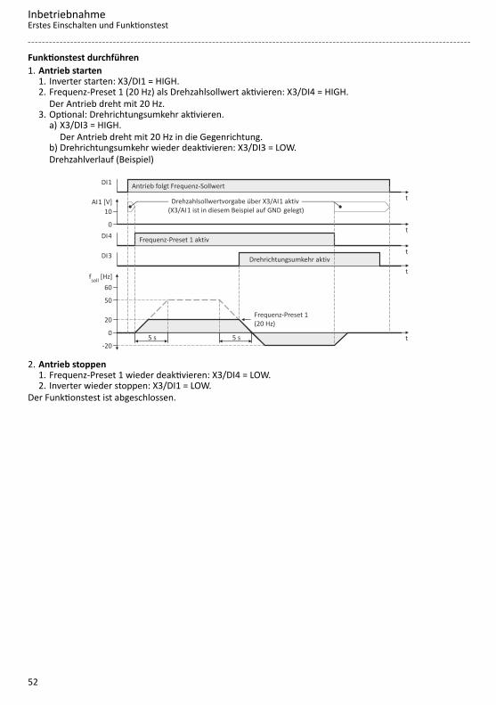
Funktionstest durchführen1. Antrieb starten
1. Inverter starten: X3/DI1 = HIGH.2. Frequenz-Preset 1 (20 Hz) als Drehzahlsollwert aktivieren: X3/DI4 = HIGH.
Der Antrieb dreht mit 20 Hz.3. Optional: Drehrichtungsumkehr aktivieren.
a) X3/DI3 = HIGH.Der Antrieb dreht mit 20 Hz in die Gegenrichtung.
b) Drehrichtungsumkehr wieder deaktivieren: X3/DI3 = LOW.Drehzahlverlauf (Beispiel)
t0
50
60
20
5 s 5 s-20
t
DI3 t
DI4t
AI1 [V]
0
10
t
DI1
f [Hz]soll
Frequenz-Preset 1 (20 Hz)
Drehzahlsollwertvorgabe über X3/ 1 aktivAI (X3/ 1 ist in diesem Beispiel auf gelegt)AI GND
Drehrichtungsumkehr aktiv
Frequenz-Preset 1 aktiv
Antrieb folgt Frequenz-Sollwert
2. Antrieb stoppen1. Frequenz-Preset 1 wieder deaktivieren: X3/DI4 = LOW.2. Inverter wieder stoppen: X3/DI1 = LOW.
Der Funktionstest ist abgeschlossen.
InbetriebnahmeErstes Einschalten und Funktionstest
52
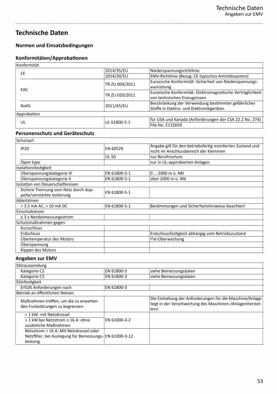
Technische DatenNormen und Einsatzbedingungen
Konformitäten/ApprobationenKonformität
CE 2014/35/EU Niederspannungsrichtlinie2014/30/EU EMV-Richtlinie (Bezug: CE-typisches Antriebssystem)
EACTR ZU 004/2011 Eurasische Konformität: Sicherheit von Niederspannungs-
ausrüstung
TR ZU 020/2011 Eurasische Konformität: Elektromagnetische Verträglichkeitvon technischen Erzeugnissen
RoHS 2011/65/EU Beschränkung der Verwendung bestimmter gefährlicherStoffe in Elektro- und Elektronikgeräten
Approbation UL UL 61800-5-1 für USA und Kanada (Anforderungen der CSA 22.2 No. 274) File No. E132659
Personenschutz und GeräteschutzSchutzart
IP20 EN 60529 Angabe gilt für den betriebsfertig montierten Zustand undnicht im Anschlussbereich der Klemmen
UL 50 nur Berührschutz Open type nur in UL-approbierten AnlagenIsolationsfestigkeit Überspannungskategorie III EN 61800-5-1 0 … 2000 m ü. NN Überspannungskategorie II EN 61800-5-1 über 2000 m ü. NNIsolation von Steuerschaltkreisen
Sichere Trennung vom Netz durch dop-pelte/verstärkte Isolierung EN 61800-5-1
Ableitstrom > 3.5 mA AC, > 10 mA DC EN 61800-5-1 Bestimmungen und Sicherheitshinweise beachten!Einschaltstrom ≤ 3 x Netzbemessungsstrom Schutzmaßnahmen gegen Kurzschluss Erdschluss Erdschlussfestigkeit abhängig vom Betriebszustand Übertemperatur des Motors I²xt-Überwachung Überspannung Kippen des Motors
Angaben zur EMVStöraussendung Kategorie C2 EN 61800-3 siehe Bemessungsdaten Kategorie C3 EN 61800-3 siehe BemessungsdatenStörfestigkeit Erfüllt Anforderungen nach EN 61800-3 Betrieb an öffentlichen Netzen
Maßnahmen treffen, um die zu erwarten-den Funkstörungen zu begrenzen:
Die Einhaltung der Anforderungen für die Maschine/Anlageliegt in der Verantwortung des Maschinen-/Anlagenherstel-lers!
< 1 kW: mit Netzdrossel
EN 61000-3-2 > 1 kW bei Netzstrom ≤ 16 A: ohnezusätzliche Maßnahmen
Netzstrom > 16 A: Mit Netzdrossel oderNetzfilter, bei Auslegung für Bemessungs-leistung.
EN 61000-3-12
Technische DatenAngaben zur EMV
53

MotoranschlussAnforderungen an die geschirmte Motorleitung Kapazitätsbelag
C-Ader-Ader/C-Ader-Schirm < 75/150pF/m
≤ 2.5 mm² / AWG 14
C-Ader-Ader/C-Ader-Schirm < 150/300pF/m ≥ 4 mm² / AWG 12
Spannungsfestigkeit
Uo/U = 0.6/1.0 kV Uo = Effektivwert Außenleiter zu PEU = Effektivwert Außenleiter zu Außenleiter
U ≥ 600 V UL U = Effektivwert Außenleiter zu Außenleiter
UmweltbedingungenEnergieeffizienz Klasse IE2 EN 50598-2 Klima 1K3 (-25 ... +60 °C) EN 60721-3-1 Lagerung 2K3 (-25 ... +70 °C) EN 60721-3-2 Transport 3K3 (-10 ... +55 °C) EN 60721-3-3 Betrieb
Betrieb bei Schaltfrequenz 2 oder 4 kHz: Über +45 °C Aus-gangsbemessungsstrom um 2.5 %/°C reduzieren
Betrieb bei Schaltfrequenz 8 oder 16 kHz: Über +40 °C Aus-gangsbemessungsstrom um 2.5 %/°C reduzieren
Aufstellhöhe 0 … 1000 m ü. NN 1000 … 4000 m ü. NN Ausgangsbemessungsstrom um 5 %/1000 m reduzierenVerschmutzung Verschmutzungsgrad 2 EN 61800-5-1 UL 61800-5-1Vibrationsfestigkeit Transport 2M2 (Sinus, Schock) EN 60721-3-2 in Originalverpackung Betrieb
Amplitude 1 mm Germanischer Lloyd 5 ... 13.2 Hzbeschleunigungsfest bis 0.7 g 13.2 ... 100 Hz
Amplitude 0.075 mm EN 61800-5-1 10 ... 57 Hz beschleunigungsfest bis 1 g 57 ... 150 Hz
NetzbedingungenZulässige Netzsysteme TT Spannung gegen Erde: max. 300 V TN Spannung gegen Erde: max. 300 V IT Die für IT-Netze beschriebenen Maßnahmen anwenden! IT-Netze nicht relevant für UL-approbierte Anlagen
Technische DatenNormen und EinsatzbedingungenNetzbedingungen
54

1-phasiger Netzanschluss 230/240 V
BemessungsdatenDie Ausgangsströme gelten für diese Einsatzbedingungen:• Bei Schaltfrequenz 2 kHz oder 4 kHz: Umgebungstemperatur max. 45 °C.• Bei Schaltfrequenz 8 kHz oder 16 kHz: Umgebungstemperatur max. 40 °C.Inverter I51AE125B I51AE125D I51AE137B I51AE137D I51AE155B I51AE155DBemessungsleistung kW 0.25 0.25 0.37 0.37 0.55 0.55Bemessungsleistung hp 0.33 0.33 0.5 0.5 0.75 0.75Netzspannungsbereich 1/PE AC 170 V ... 264 V, 45 Hz ... 65 HzAusgangsspannung 3 AC 0-230/240 VNetzbemessungsstrom ohne Netzdrossel A 4 4 5.7 5.7 7.6 7.6 mit Netzdrossel A 3.6 3.6 4.8 4.8 7.1 7.1Ausgangsscheinleistung kVA 0.6 0.6 0.9 0.9 1.2 1.2Ausgangsbemessungsstrom 2 kHz A - - - - 3.2 3.2 4 kHz A 1.7 1.7 2.4 2.4 3.2 3.2 8 kHz A 1.7 1.7 2.4 2.4 3.2 3.2 16 kHz A 1.1 1.1 1.6 1.6 2.1 2.1Verlustleistung 2 kHz W - - - - 22 22 4 kHz W 15 15 18 18 23 23 8 kHz W 15 15 20 20 25 25 16 kHz W 19 19 24 24 30 30 bei Reglersperre W 6 6 6 6 6 6Zyklisches Netzschalten 3-mal pro MinuteMax. Motorleitungslängegeschirmt
Kategorie C2 (2 kHz, 4 kHz, 8kHz)
m 15 - 15 - 20 -
Kategorie C3 (2 kHz, 4 kHz, 8kHz)
m 15 - 15 - 50 -
ohne EMV-Kategorie m 50 50 50 50 50 50Gewicht kg 0.75 0.75 0.75 0.75 0.95 0.95Gewicht lb 1.7 1.7 1.7 1.7 2.1 2.1
Technische Daten1-phasiger Netzanschluss 230/240 V
Bemessungsdaten
55

Inverter I51AE175B I51AE175D I51AE211B I51AE211D I51AE215B I51AE215DBemessungsleistung kW 0.75 0.75 1.1 1.1 1.5 1.5Bemessungsleistung hp 1 1 1.5 1.5 2 2Netzspannungsbereich 1/PE AC 170 V ... 264 V, 45 Hz ... 65 HzAusgangsspannung 3 AC 0-230/240 VNetzbemessungsstrom ohne Netzdrossel A 10 10 14.3 14.3 16.7 16.7 mit Netzdrossel A 8.8 8.8 11.9 11.9 13.9 13.9Ausgangsscheinleistung kVA 1.6 1.6 2.2 2.2 2.6 2.6Ausgangsbemessungsstrom 2 kHz A 4.2 4.2 6 6 7 7 4 kHz A 4.2 4.2 6 6 7 7 8 kHz A 4.2 4.2 6 6 7 7 16 kHz A 2.8 2.8 4 4 4.7 4.7Verlustleistung 2 kHz W 27 27 36 36 41 41 4 kHz W 29 29 37 37 43 43 8 kHz W 33 33 42 42 50 50 16 kHz W 38 38 51 51 59 59 bei Reglersperre W 6 6 6 6 6 6Zyklisches Netzschalten 3-mal pro MinuteMax. Motorleitungslängegeschirmt
Kategorie C2 (2 kHz, 4 kHz, 8kHz)
m 20 - 20 - 20 -
Kategorie C3 (2 kHz, 4 kHz, 8kHz)
m 50 - 35 - 35 -
ohne EMV-Kategorie m 50 50 50 50 50 50Gewicht kg 0.95 0.95 1.35 1.35 1.35 1.35Gewicht lb 2.1 2.1 3 3 3 3
Inverter I51AE222B I51AE222DBemessungsleistung kW 2.2 2.2Bemessungsleistung hp 3 3Netzspannungsbereich 1/PE AC 170 V ... 264 V, 45 Hz ... 65 HzAusgangsspannung 3 AC 0-230/240 VNetzbemessungsstrom ohne Netzdrossel A 22.5 22.5 mit Netzdrossel A 16.9 16.9Ausgangsscheinleistung kVA 3.6 3.6Ausgangsbemessungsstrom 2 kHz A 9.6 9.6 4 kHz A 9.6 9.6 8 kHz A 9.6 9.6 16 kHz A 6.4 6.4Verlustleistung 2 kHz W 54 54 4 kHz W 60 60 8 kHz W 70 70 16 kHz W 78 78 bei Reglersperre W 6 6Zyklisches Netzschalten 3-mal pro MinuteMax. Motorleitungslängegeschirmt
Kategorie C2 (2 kHz, 4 kHz, 8kHz)
m 20 -
Kategorie C3 (2 kHz, 4 kHz, 8kHz)
m 35 -
ohne EMV-Kategorie m 50 50Gewicht kg 1.35 1.35Gewicht lb 3 3
Technische Daten1-phasiger Netzanschluss 230/240 VBemessungsdaten
56
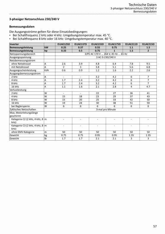
3-phasiger Netzanschluss 230/240 V
BemessungsdatenDie Ausgangsströme gelten für diese Einsatzbedingungen:• Bei Schaltfrequenz 2 kHz oder 4 kHz: Umgebungstemperatur max. 45 °C.• Bei Schaltfrequenz 8 kHz oder 16 kHz: Umgebungstemperatur max. 40 °C.Inverter I51AE125D I51AE137D I51AE155D I51AE175D I51AE211D I51AE215DBemessungsleistung kW 0.25 0.37 0.55 0.75 1.1 1.5Bemessungsleistung hp 0.33 0.5 0.75 1 1.5 2Netzspannungsbereich 3/PE AC 170 V ... 264 V, 45 Hz ... 65 HzAusgangsspannung 3 AC 0-230/240 VNetzbemessungsstrom ohne Netzdrossel A 2.6 3.9 4.8 6.4 7.8 9.5 mit Netzdrossel A 2 3 3.8 5.1 5.6 6.8Ausgangsscheinleistung kVA 0.6 0.9 1.2 1.6 2.2 2.6Ausgangsbemessungsstrom 2 kHz A - - 3.2 4.2 6 7 4 kHz A 1.7 2.4 3.2 4.2 6 7 8 kHz A 1.7 2.4 3.2 4.2 6 7 16 kHz A 1.1 1.6 2.1 2.8 4 4.7Verlustleistung 2 kHz W - - 22 27 36 41 4 kHz W 15 18 23 29 37 43 8 kHz W 15 20 25 33 42 50 16 kHz W 19 24 30 38 51 59 bei Reglersperre W 6 6 6 6 6 6Zyklisches Netzschalten 3-mal pro MinuteMax. Motorleitungslängegeschirmt
Kategorie C2 (2 kHz, 4 kHz, 8kHz)
m - - - - - -
Kategorie C3 (2 kHz, 4 kHz, 8kHz)
m - - - - - -
ohne EMV-Kategorie m 50 50 50 50 50 50Gewicht kg 0.75 0.75 0.95 0.95 1.35 1.35Gewicht lb 1.7 1.7 2.1 2.1 3 3
Technische Daten3-phasiger Netzanschluss 230/240 V
Bemessungsdaten
57

Inverter I51AE222D I51AE240C I51AE255CBemessungsleistung kW 2.2 4 5.5Bemessungsleistung hp 3 5 7.5Netzspannungsbereich 3/PE AC 170 V ... 264 V, 45 Hz ... 65 HzAusgangsspannung 3 AC 0-230/240 VNetzbemessungsstrom ohne Netzdrossel A 13.6 20.6 28.8 mit Netzdrossel A 9.8 15.7 21.9Ausgangsscheinleistung kVA 3.6 6.4 8.7Ausgangsbemessungsstrom 2 kHz A 9.6 16.5 23 4 kHz A 9.6 16.5 23 8 kHz A 9.6 16.5 23 16 kHz A 6.4 11 15.3Verlustleistung 2 kHz W 54 113 166 4 kHz W 60 115 175 8 kHz W 70 130 195 16 kHz W 78 116 159 bei Reglersperre W 6 6 6Zyklisches Netzschalten 3-mal pro MinuteMax. Motorleitungslängegeschirmt
Kategorie C2 (2 kHz, 4 kHz, 8kHz)
m - - -
Kategorie C3 (2 kHz, 4 kHz, 8kHz)
m - - -
ohne EMV-Kategorie m 50 50 50Gewicht kg 1.35 2.1 2.1Gewicht lb 3 4.6 4.6
Technische Daten3-phasiger Netzanschluss 230/240 VBemessungsdaten
58

3-phasiger Netzanschluss 230/240 V "Light Duty"
BemessungsdatenDie Ausgangsströme gelten für diese Einsatzbedingungen:• Bei Schaltfrequenz 2 kHz oder 4 kHz: Umgebungstemperatur über. 40 °C mit 2.5 %/°C reduziertem Aus-
gangsbemessungsstrom.• Bei gewählter Lastcharakteristik "Light Duty" und Auswahl der Schaltfrequenzen 8 kHz oder 16 kHz wer-
den nur die Werte der Lastcharakteristik "Heavy Duty" erreicht.Inverter I51AE240C I51AE255CBemessungsleistung kW 5.5 7.5Bemessungsleistung hp 7.5 10Netzspannungsbereich 3/PE AC 170 V ... 264 V, 45 Hz ... 65 HzAusgangsspannung 3 AC 0-230/240 VNetzbemessungsstrom ohne Netzdrossel A 25.8 - mit Netzdrossel A 18.9 24.2Ausgangsscheinleistung kVA 8 10.5Ausgangsbemessungsstrom 2 kHz A 20.6 27.6 4 kHz A 20.6 27.6 8 kHz A - - 16 kHz A - -Verlustleistung 2 kHz W 124 190 4 kHz W 131 200 8 kHz W - - 16 kHz W - - bei Reglersperre W 6 6Zyklisches Netzschalten 3-mal pro MinuteMax. Motorleitungslängegeschirmt
Kategorie C2 (2 kHz, 4 kHz, 8kHz)
m - -
Kategorie C3 (2 kHz, 4 kHz, 8kHz)
m - -
ohne EMV-Kategorie m 50 50Gewicht kg 2.1 2.1Gewicht lb 4.6 4.6
Technische Daten3-phasiger Netzanschluss 230/240 V "Light Duty"
Bemessungsdaten
59
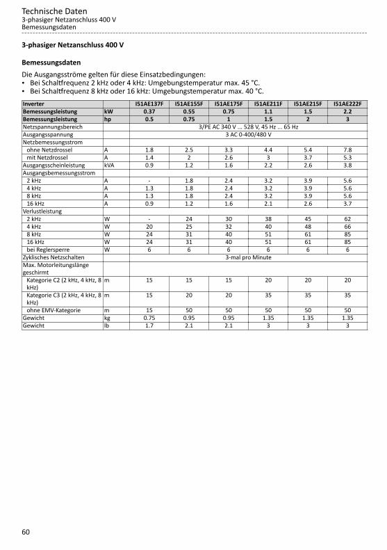
3-phasiger Netzanschluss 400 V
BemessungsdatenDie Ausgangsströme gelten für diese Einsatzbedingungen:• Bei Schaltfrequenz 2 kHz oder 4 kHz: Umgebungstemperatur max. 45 °C.• Bei Schaltfrequenz 8 kHz oder 16 kHz: Umgebungstemperatur max. 40 °C.Inverter I51AE137F I51AE155F I51AE175F I51AE211F I51AE215F I51AE222FBemessungsleistung kW 0.37 0.55 0.75 1.1 1.5 2.2Bemessungsleistung hp 0.5 0.75 1 1.5 2 3Netzspannungsbereich 3/PE AC 340 V ... 528 V, 45 Hz ... 65 HzAusgangsspannung 3 AC 0-400/480 VNetzbemessungsstrom ohne Netzdrossel A 1.8 2.5 3.3 4.4 5.4 7.8 mit Netzdrossel A 1.4 2 2.6 3 3.7 5.3Ausgangsscheinleistung kVA 0.9 1.2 1.6 2.2 2.6 3.8Ausgangsbemessungsstrom 2 kHz A - 1.8 2.4 3.2 3.9 5.6 4 kHz A 1.3 1.8 2.4 3.2 3.9 5.6 8 kHz A 1.3 1.8 2.4 3.2 3.9 5.6 16 kHz A 0.9 1.2 1.6 2.1 2.6 3.7Verlustleistung 2 kHz W - 24 30 38 45 62 4 kHz W 20 25 32 40 48 66 8 kHz W 24 31 40 51 61 85 16 kHz W 24 31 40 51 61 85 bei Reglersperre W 6 6 6 6 6 6Zyklisches Netzschalten 3-mal pro MinuteMax. Motorleitungslängegeschirmt
Kategorie C2 (2 kHz, 4 kHz, 8kHz)
m 15 15 15 20 20 20
Kategorie C3 (2 kHz, 4 kHz, 8kHz)
m 15 20 20 35 35 35
ohne EMV-Kategorie m 15 50 50 50 50 50Gewicht kg 0.75 0.95 0.95 1.35 1.35 1.35Gewicht lb 1.7 2.1 2.1 3 3 3
Technische Daten3-phasiger Netzanschluss 400 VBemessungsdaten
60

Inverter I51AE230F I51BE230F I51AE240F I51BE240F I51AE255F I51AE275F I51AE311FBemessungsleistung kW 3 3 4 4 5.5 7.5 11Bemessungsleistung hp 4 4 5 5 7.5 10 15Netzspannungsbereich 3/PE AC 340 V ... 528 V, 45 Hz ... 65 HzAusgangsspannung 3 AC 0-400/480 VNetzbemessungsstrom ohne Netzdrossel A 9.6 9.6 12.5 12.5 17.2 20 28.4 mit Netzdrossel A 6.9 6.9 9 9 12.4 15.7 22.3Ausgangsscheinleistung kVA 4.9 4.9 6.4 6.4 8.7 11 16Ausgangsbemessungsstrom 2 kHz A 7.3 7.3 9.5 9.5 13 16.5 23.5 4 kHz A 7.3 7.3 9.5 9.5 13 16.5 23.5 8 kHz A 7.3 7.3 9.5 9.5 13 16.5 23.5 16 kHz A 4.9 4.9 6.3 6.3 8.7 11 15.7Verlustleistung 2 kHz W 79 79 102 102 137 172 242 4 kHz W 85 85 110 110 145 185 260 8 kHz W 110 110 140 140 190 240 340 16 kHz W 109 109 140 140 189 238 337 bei Reglersperre W 6 6 6 6 6 6 6Zyklisches Netzschalten 3-mal pro MinuteMax. Motorleitungslängegeschirmt
Kategorie C2 (2 kHz, 4 kHz, 8kHz)
m 20 20 20 20 20 20 20
Kategorie C3 (2 kHz, 4 kHz, 8kHz)
m 35 35 35 35 35 50 50
ohne EMV-Kategorie m 100 50 100 50 100 100 100Gewicht kg 2.3 1.35 2.3 1.35 2.3 3.7 3.7Gewicht lb 5 3 5 3 5 8 8
Technische Daten3-phasiger Netzanschluss 400 V
Bemessungsdaten
61

3-phasiger Netzanschluss 400 V "Light Duty"
BemessungsdatenDie Ausgangsströme gelten für diese Einsatzbedingungen:• Bei Schaltfrequenz 2 kHz oder 4 kHz: Umgebungstemperatur über. 40 °C mit 2.5 %/°C reduziertem Aus-
gangsbemessungsstrom.• Bei gewählter Lastcharakteristik "Light Duty" und Auswahl der Schaltfrequenzen 8 kHz oder 16 kHz wer-
den nur die Werte der Lastcharakteristik "Heavy Duty" erreicht.Inverter I51AE230F I51BE230F I51AE240F I51BE240F I51AE255F I51AE275F I51AE311FBemessungsleistung kW 4 4 5.5 5.5 7.5 11 15Bemessungsleistung hp 5 5 7.5 7.5 10 15 20Netzspannungsbereich 3/PE AC 340 V ... 528 V, 45 Hz ... 65 HzAusgangsspannung 3 AC 0-400/480 VNetzbemessungsstrom ohne Netzdrossel A 10.3 10.3 14 14 18.3 28 - mit Netzdrossel A 8.2 8.2 11 11 14.5 22 27.1Ausgangsscheinleistung kVA 5.9 5.9 8 8 10.5 15 19Ausgangsbemessungsstrom 2 kHz A 8.8 8.8 11.9 11.9 15.6 23 28.2 4 kHz A 8.8 8.8 11.9 11.9 15.6 23 28.2 8 kHz A - - - - - - - 16 kHz A - - - - - - -Verlustleistung 2 kHz W 94 94 125 125 163 238 290 4 kHz W 100 100 133 133 173 253 309 8 kHz W - - - - - - - 16 kHz W - - - - - - - bei Reglersperre W 6 6 6 6 6 6 6Zyklisches Netzschalten 3-mal pro MinuteMax. Motorleitungslängegeschirmt
Kategorie C2 (2 kHz, 4 kHz, 8kHz)
m 20 20 20 20 20 20 20
Kategorie C3 (2 kHz, 4 kHz, 8kHz)
m 35 35 35 35 35 50 50
ohne EMV-Kategorie m 100 50 100 50 100 100 100Gewicht kg 2.3 1.35 2.3 1.35 2.3 3.7 3.7Gewicht lb 5 3 5 3 5 8 8
Technische Daten3-phasiger Netzanschluss 400 V "Light Duty"Bemessungsdaten
62

3-phasiger Netzanschluss 480 V
BemessungsdatenDie Ausgangsströme gelten für diese Einsatzbedingungen:• Bei Schaltfrequenz 2 kHz oder 4 kHz: Umgebungstemperatur max. 45 °C.• Bei Schaltfrequenz 8 kHz oder 16 kHz: Umgebungstemperatur max. 40 °C.Inverter I51AE137F I51AE155F I51AE175F I51AE211F I51AE215F I51AE222FBemessungsleistung kW 0.37 0.55 0.75 1.1 1.5 2.2Bemessungsleistung hp 0.5 0.75 1 1.5 2 3Netzspannungsbereich 3/PE AC 340 V ... 528 V, 45 Hz ... 65 HzAusgangsspannung 3 AC 0-400/480 VNetzbemessungsstrom ohne Netzdrossel A 1.5 2.1 2.8 3.7 4.5 6.5 mit Netzdrossel A 1.2 1.7 2.2 2.5 3.1 4.4Ausgangsscheinleistung kVA 0.9 1.2 1.6 2.2 2.6 3.8Ausgangsbemessungsstrom 2 kHz A - 1.6 2.1 3 3.5 4.8 4 kHz A 1.1 1.6 2.1 3 3.5 4.8 8 kHz A 1.1 1.6 2.1 3 3.5 4.8 16 kHz A 0.7 1.1 1.4 2 2.3 3.2Verlustleistung 2 kHz W - 24 30 38 45 62 4 kHz W 20 25 32 40 48 66 8 kHz W 24 31 40 51 61 85 16 kHz W 24 31 40 51 61 85 bei Reglersperre W 6 6 6 6 6 6Zyklisches Netzschalten 3-mal pro MinuteMax. Motorleitungslängegeschirmt
Kategorie C2 (2 kHz, 4 kHz, 8kHz)
m 15 15 15 20 20 20
Kategorie C3 (2 kHz, 4 kHz, 8kHz)
m 15 20 20 35 35 35
ohne EMV-Kategorie m 15 50 50 50 50 50Gewicht kg 0.75 0.95 0.95 1.35 1.35 1.35Gewicht lb 1.7 2.1 2.1 3 3 3
Technische Daten3-phasiger Netzanschluss 480 V
Bemessungsdaten
63
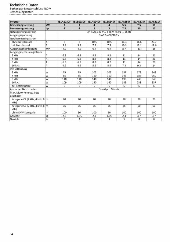
Inverter I51AE230F I51BE230F I51AE240F I51BE240F I51AE255F I51AE275F I51AE311FBemessungsleistung kW 3 3 4 4 5.5 7.5 11Bemessungsleistung hp 4 4 5 5 7.5 10 15Netzspannungsbereich 3/PE AC 340 V ... 528 V, 45 Hz ... 65 HzAusgangsspannung 3 AC 0-400/480 VNetzbemessungsstrom ohne Netzdrossel A 8 8 10.5 10.5 14.3 16.6 23.7 mit Netzdrossel A 5.8 5.8 7.5 7.5 10.3 13.1 18.6Ausgangsscheinleistung kVA 4.9 4.9 6.4 6.4 8.7 11 16Ausgangsbemessungsstrom 2 kHz A 6.3 6.3 8.2 8.2 11 14 21 4 kHz A 6.3 6.3 8.2 8.2 11 14 21 8 kHz A 6.3 6.3 8.2 8.2 11 14 21 16 kHz A 4.2 4.2 5.5 5.5 7.3 9.3 14Verlustleistung 2 kHz W 79 79 102 102 137 172 242 4 kHz W 85 85 110 110 145 185 260 8 kHz W 110 110 140 140 190 240 340 16 kHz W 109 109 140 140 189 238 337 bei Reglersperre W 6 6 6 6 6 6 6Zyklisches Netzschalten 3-mal pro MinuteMax. Motorleitungslängegeschirmt
Kategorie C2 (2 kHz, 4 kHz, 8kHz)
m 20 20 20 20 20 20 20
Kategorie C3 (2 kHz, 4 kHz, 8kHz)
m 35 35 35 35 35 50 50
ohne EMV-Kategorie m 100 50 100 50 100 100 100Gewicht kg 2.3 1.35 2.3 1.35 2.3 3.7 3.7Gewicht lb 5 3 5 3 5 8 8
Technische Daten3-phasiger Netzanschluss 480 VBemessungsdaten
64

3-phasiger Netzanschluss 480 V "Light Duty"
BemessungsdatenDie Ausgangsströme gelten für diese Einsatzbedingungen:• Bei Schaltfrequenz 2 kHz oder 4 kHz: Umgebungstemperatur über. 40 °C mit 2.5 %/°C reduziertem Aus-
gangsbemessungsstrom.• Bei gewählter Lastcharakteristik "Light Duty" und Auswahl der Schaltfrequenzen 8 kHz oder 16 kHz wer-
den nur die Werte der Lastcharakteristik "Heavy Duty" erreicht.Inverter I51AE230F I51BE230F I51AE240F I51BE240F I51AE255F I51AE275F I51AE311FBemessungsleistung kW 4 4 5.5 5.5 7.5 11 15Bemessungsleistung hp 5 5 7.5 7.5 10 15 20Netzspannungsbereich 3/PE AC 340 V ... 528 V, 45 Hz ... 65 HzAusgangsspannung 3 AC 0-400/480 VNetzbemessungsstrom ohne Netzdrossel A 8.6 8.6 11.2 11.2 15.3 22 - mit Netzdrossel A 6.8 6.8 8.8 8.8 12.1 17.2 22.6Ausgangsscheinleistung kVA 5.9 5.9 8 8 10.5 15 19Ausgangsbemessungsstrom 2 kHz A 7.6 7.6 9.8 9.8 13.2 18.3 25.2 4 kHz A 7.6 7.6 9.8 9.8 13.2 18.3 25.2 8 kHz A - - - - - - - 16 kHz A - - - - - - -Verlustleistung 2 kHz W 94 94 125 125 163 238 290 4 kHz W 100 100 133 133 173 253 309 8 kHz W - - - - - - - 16 kHz W - - - - - - - bei Reglersperre W 6 6 6 6 6 6 6Zyklisches Netzschalten 3-mal pro MinuteMax. Motorleitungslängegeschirmt
Kategorie C2 (2 kHz, 4 kHz, 8kHz)
m 20 20 20 20 20 20 20
Kategorie C3 (2 kHz, 4 kHz, 8kHz)
m 35 35 35 35 35 50 50
ohne EMV-Kategorie m 100 50 100 50 100 100 100Gewicht kg 2.3 1.35 2.3 1.35 2.3 3.7 3.7Gewicht lb 5 3 5 3 5 8 8
Technische Daten3-phasiger Netzanschluss 480 V "Light Duty"
Bemessungsdaten
65

66

ContentsAbout this document 70
Document description 70Further documents 70
Notations and conventions 71Safety instructions 72
Basic safety instructions 72Application as directed 73Handling 73Residual hazards 74
Product information 75Identification of the products 75Features 76
Mechanical installation 80Important notes 80Preparation 81Dimensions 83
Contents
67
Electrical installation 95Important notes 95Connection according to UL 96Mains connection 100
1-phase mains connection 230/240 V 100Connection diagrams 100Terminal data 102Fusing data 102
3-phase mains connection 230/240 V 103Connection diagrams 103Terminal data 105Fusing data 105
3-phase mains connection 230/240 V "Light Duty" 105Connection diagrams 105Terminal data 105Fusing data 105
3-phase mains connection 400 V 106Connection diagrams 106Terminal data 107Fusing data 107
3-phase mains connection 400 V "Light Duty" 108Connection diagrams 108Terminal data 108Fusing data 108
3-phase mains connection 480 V 109Connection diagrams 109Terminal data 109Fusing data 110
3-phase mains connection 480 V "Light Duty" 110Connection diagrams 110Terminal data 110Fusing data 110
Connection to the IT system 111Control connections 112Networks 113
CANopen/Modbus 113BACnet 114
Commissioning 115Important notes 115Initial switch-on and functional test 116
Contents
68
Technical data 118Standards and operating conditions 118
Conformities/approvals 118Protection of persons and device protection 118EMC data 118Motor connection 119Environmental conditions 119Electrical supply conditions 119
1-phase mains connection 230/240 V 120Rated data 120
3-phase mains connection 230/240 V 122Rated data 122
3-phase mains connection 230/240 V "Light Duty" 124Rated data 124
3-phase mains connection 400 V 125Rated data 125
3-phase mains connection 400 V "Light Duty" 127Rated data 127
3-phase mains connection 480 V 128Rated data 128
3-phase mains connection 480 V "Light Duty" 130Rated data 130
Contents
69

About this document
WARNING!Read this documentation carefully before starting any work.▶ Please observe the safety instructions!
Document description
Further documentsFor certain tasks, information is available in other forms.Form Contents/topicsEngineering Tools For commissioningAKB articles Application Knowledge Base with additional technical information for usersCAD data Exports in different formatsEPLAN macros Project planning, documentation and management of projects for P8.
• Data reference via Lenze or EPLAN data portal
Information and tools with regard to the Lenze products can be found on the Internet:http://www.lenze.com à Downloads
About this documentDocument descriptionFurther documents
70

Notations and conventions
This document uses the following conventions to distinguish different types of information:Numeric notation Decimal separator Point The decimal point is always used.
Example: 1 234.56Warning UL warning UL Are used in English and French. UR warning URText Engineering tools » « Software
Example: »Engineer«, »EASY Starter«Icons Page reference ¶ Reference to another page with additional information
Example: ¶ 16 = see page 16 Documentation reference , Reference to another documentation with additional information
Example: , EDKxxx = see documentation EDKxxx
Layout of the safety instructions
DANGER!Indicates an extremely hazardous situation. Failure to comply with this instruction will result in severeirreparable injury and even death.
WARNING!Indicates an extremely hazardous situation. Failure to comply with this instruction may result in severeirreparable injury and even death.
CAUTION!Indicates a hazardous situation. Failure to comply with this instruction may result in slight to medium injury.
NOTICEIndicates a material hazard. Failure to comply with this instruction may result in material damage.
About this documentNotations and conventions
71

Safety instructionsDisregarding the following basic safety measures and safety information may lead to severe personal injuryand damage to property!Observe all specifications of the corresponding documentation supplied. This is the precondition for safeand trouble-free operation and for obtaining the product features specified.Please observe the specific safety information in the other sections!
DANGER!Electrical voltagePossible consequences: Death or severe injuries▶ Any work on the inverter must only be carried out in the deenergised state.▶ Inverter up to 45 kW: After switching off the mains voltage, wait for at least 3 min before you start
working.▶ Inverter from 55 kW onwards: After switching off the mains voltage, wait for at least 10 min before you
start working.
Basic safety instructions
DANGER!Dangerous electrical voltageDeath or severe injuries from electric shock.▶ Any work on the inverter must only be carried out in a deenergized state.▶ After switching off the mains voltage, observe the signs on the product.
PersonnelThe product must only be used by qualified personnel. IEC 60364 or CENELEC HD 384 define the skills ofthese persons:• They are familiar with installing, mounting, commissioning, and operating the product.• They have the corresponding qualifications for their work.• They know and can apply all regulations for the prevention of accidents, directives, and laws applicable at
the place of use.
Process engineeringThe procedural notes and circuit details described are only proposals. It is up to the user to check whetherthey can be adapted to the particular applications. Lenze does not take any responsibility for the suitabilityof the procedures and circuit proposals described.Device protection• The maximum test voltage for insulation tests between a control potential of 24 V and PE must not
exceed 110 V DC (EN 61800−5−1).
Safety instructionsBasic safety instructions
72

Application as directed
• The product must only be operated under the operating conditions prescribed in this documentation.• The product meets the protection requirements of 2014/35/EU: Low-Voltage Directive.• The product is not a machine in terms of 2006/42/EU: Machinery Directive.• Commissioning or starting the operation as directed of a machine with the product is not permitted until
it has been ensured that the machine meets the regulations of the EU Directive 2006/42/EU: MachineryDirective; observe EN 60204−1.
• Commissioning or starting operation as directed is only permissible if the EMC Directive 2014/30/EU iscomplied with.
• The harmonised standard EN 61800−5−1 is applied.• The product is not a household appliance, but is only designed as a component for commercial or
professional use in terms of EN 61000−3−2.• The product can be used according to the technical data if drive systems have to comply with categories
according to EN 61800−3.In residential areas, the product may cause EMC interferences. The operator is responsible for takinginterference suppression measures.
• The product must only be actuated with motors that are suitable for the operation with inverters.- Lenze L-force motors meet the requirements- Exception: m240 motors are designed for mains operation only.
Handling
• Never commission the product in the event of visible damage.• The product must never be technically modified.• Never commission the product before assembly has been completed.• The product must never be operated without required covers.• Establish, separate and change all electrical connections only in deenergised state!
Safety instructionsHandling
73

Residual hazards
Even if notes given are taken into consideration and protective measures are implemented, the occurrenceof residual risks cannot be fully prevented.The user must take the residual hazards mentioned into consideration in the risk assessment for his/hermachine/system.If the above is disregarded, this can lead to severe injuries to persons and damage to property!
ProductObserve the warning labels on the product!Icon Description
Electrostatic sensitive devices:Before working on the product, the staff must ensure to be free of electrostatic charge!
Dangerous electrical voltageBefore working on the product, make sure there is no voltage applied to the power terminals!After mains disconnection, the power terminals will still carry the hazardous electrical voltage for the timegiven next to the symbol!High leakage current:Carry out fixed installation and PE connection in compliance with EN 61800−5−1 or EN 60204−1!
Hot surface:Use personal protective equipment or wait until the device has cooled down!
Motor protectionWith some settings of the inverter, the connected motor can be overheated.• E. g. by longer operation of self-ventilated motors at low speed.• E. g. by longer operation of the DC-injection brake.
Protection of the machine/systemDrives can reach dangerous overspeeds.• E. g. by setting high output frequencies in connection with motors and machines not suitable for this
purpose.• The inverters do not provide protection against such operating conditions. For this purpose, use
additional components.
Switch contactors in the motor cable only if the controller is inhibited.• Switching while the inverter is enabled is only permissible if no monitoring functions are activated.
MotorIf there is a short circuit of two power transistors, a residual movement of up to 180°/number of pole pairscan occur at the motor! (e. g. 4-pole motor: residual movement max. 180°/2 = 90°).Degree of protection - protection of persons and device protection• Information applies to the mounted and ready-for-use state.• Information does not apply to the wire range of the terminals.- Terminals that are not wired have low protection against physical contact.- Terminals for large cable cross-sections have lower classes of protection, e. g. from 15 kW IP10 only.
Safety instructionsResidual hazards
74

Product informationIdentification of the products
In tables, the first 9 digits of the corresponding product code are used to identify the products:Product code I 5 1 A E □□□ □ 1 0 □ □ □ □□□□Product type Inverter I Product family i500 5 Product i510 1 Product generation Generation 1 A
Generation 2 B Mounting type Control cabinet mounting E Rated power(Example)
0.25 kW 125 0.55 kW 155 2.2 kW 222
Mains voltqge and connection type 1/N/PE AC 230/240 V B 1/N/PE AC 230/240 V2/N/PE AC 230/240 V D
3/PE AC 230/240 V C 3/PE AC 400 V3/PE AC 480 V
F
Motor connections Single axis 1 Integrated functional safety Without safety function 0 Degree of protection IP20 0
IP20, coated V Interference suppression Without 0
Integrated RFI filter 1 Design types Global model 50 Hz 0
Local model 60 Hz 1 Basic-I/O without network 000SBasic-I/O with CANopen/Modbus 001S
Example:Product code MeaningI51AE215F10010001S Inverter i510 Cabinet, 1.5 kW, three-phase, 400 V/480 V
IP20, integrated RFI filter, 50-Hz versionBasic I/O with CANopen/Modbus network
Product informationIdentification of the products
75

Features
Example of 0.25 kW ... 4 kW
Shield connection
PE connection Mains connection/DC bus
Relay output
Network
Interface
Control terminals
Shielding of control connectionsIT screw
IT screw from 0.55 kW
Inverter status s LED
Motor connection
Option
Option
Basic I/O
Diagnostic module
Brake resistor connection
Memory moduleNetword status s LED
Toggle switch CANopen/Modbus
X100
X16
X3
X20
X105
X216
X9
Product informationFeatures
76

Example of 0.25 kW ... 2.2 kWEarth / ground connec!on (PE) Mains voltage connec!on X100
Relay output X9
Network X2xx
Memory module X20
IT screw
Inverter status LEDsShield connec!on
IT screw
Network status-LEDs
Motor connec!on X105
CANopen/Modbus (Op!on)
CANopen/Modbus
Shield connec!on
Control connec!ons
Control terminals X3
Basic I/O
Interface X16
Diagnos!c module
from 0.55 kW
Toggle switch
CANopen/Modbus
Product informationFeatures
77

Example of 5.5 kW
X3
X20
X100
X16
X105
X216X9
CANopen/ModbusSelector
Network status LEDs
Diagnostic module
Basic I/OControl connections
CANopen/Modbus
CANopen/Modbus (option)
Memory module
Motor connection
Inverter status LEDs
Shield connection
IT screw
Shield connection Control terminals
Interface
NetworkRelay output
Mains connection
PE connection
Product informationFeatures
78

Example of 7.5 kW ... 11 kW
X3
X20
X100
X16
X105
X216
X9
CANopen/ModbusSelector
Network status LEDs
Diagnostic module
Basic I/OControl connections
CANopen/Modbus
CANopen/Modbus (option)
Memory module
Motor connection
Inverter status LEDs
Shield connection
IT screw
Shield connectionControl terminals
Interface
Network
Relay output
Mains connectionPE connection
Product informationFeatures
79

Mechanical installationImportant notes
NOTICE▶ UL marking▶ Modular construction - A complete drive consists of a power unit series no. I5D in combination with a
control unit series no. I5C only.▶ Marquage UL▶ Conception modulaire – Le système d’entraînement complet comprend un module d’alimentation de
série I5D, impérativement associé à une unité de commande de série I5C.
Mechanical installationImportant notes
80

Preparation
Installation of shield connection sheet for the motor cable 0.25 kW to 4 kW (optional accessories)
3.4 Nm(30 lb-in)
❶ ❷
M5
❸
Together with the inverter, the shield connection sheet is screwed onto the mounting plate.
Installation of shield connection sheet for the motor cable 5.5 kW (optional accessories)
2 Nm(17.7 lb-in)
❶ ❷
M4x12
❸
Mechanical installationPreparation
81

Installation of shield connection sheet for the motor cable 7.5 kW to 11 kW (optional accessories)
2 Nm(17.7 lb-in)
❶ ❷
M4x12
❸
Mechanical installationPreparation
82

Dimensions
0.25 kW ... 0.37 kWThe dimensions in mm apply to:0.25 kW I51AE125B I51AE125D 0.37 kW I51AE137B I51AE137D I51AE137F
Mechanical installationDimensions
83

0.33 hp ... 0.5 hpThe dimensions in inch apply to:0.33 hp I51AE125B I51AE125D 0.5 hp I51AE137B I51AE137D I51AE137F
Mechanical installationDimensions
84
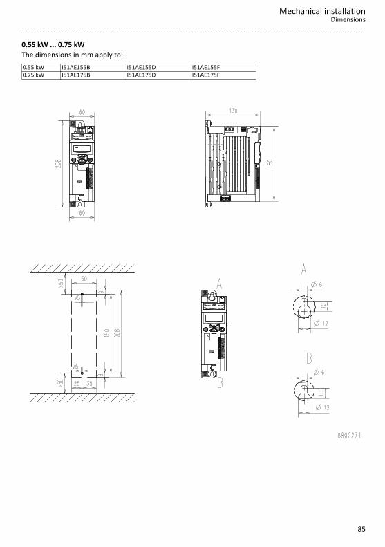
0.55 kW ... 0.75 kWThe dimensions in mm apply to:0.55 kW I51AE155B I51AE155D I51AE155F0.75 kW I51AE175B I51AE175D I51AE175F
Mechanical installationDimensions
85
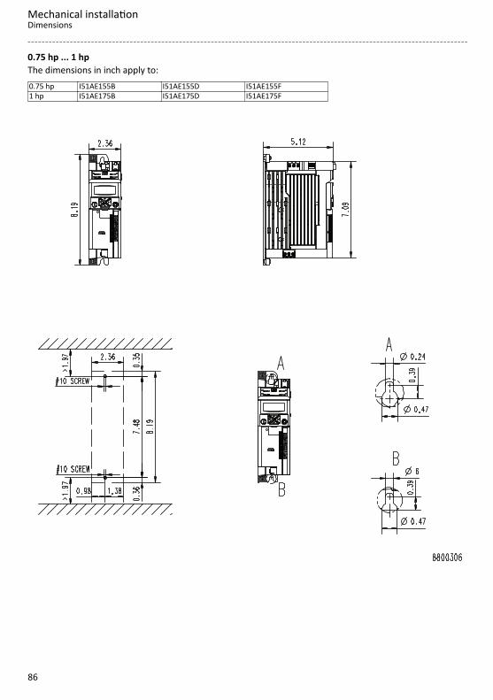
0.75 hp ... 1 hpThe dimensions in inch apply to:0.75 hp I51AE155B I51AE155D I51AE155F1 hp I51AE175B I51AE175D I51AE175F
Mechanical installationDimensions
86

1.1 kW ... 4 kWThe dimensions in mm apply to:1.1 kW I51AE211B I51AE211D I51AE211F1.5 kW I51AE215B I51AE215D I51AE215F2.2 kW I51AE222B I51AE222D I51AE222F3 kW I51BE230F4 kW I51BE240F
Mechanical installationDimensions
87

1.5 hp ... 5.5 hpThe dimensions in inch apply to:1.5 hp I51AE211B I51AE211D I51AE211F2 hp I51AE215B I51AE215D I51AE215F3 hp I51AE222B I51AE222D I51AE222F4 hp I51BE230F5.5 hp I51BE240F
Mechanical installationDimensions
88

1.1 kW ... 2.2 kWThe dimensions in mm apply to:1.1 kW I51AE211B I51AE211D I51AE211F1.5 kW I51AE215B I51AE215D I51AE215F2.2 kW I51AE222B I51AE222D I51AE222F
Mechanical installationDimensions
89

1.5 hp ... 3 hpThe dimensions in inch apply to:1.5 hp I51AE211B I51AE211D I51AE211F2 hp I51AE215B I51AE215D I51AE215F3 hp I51AE222B I51AE222D I51AE222F
Mechanical installationDimensions
90

5.5 kWThe dimensions in mm apply to:5.5 kW I51AE255C I51AE255F
Mechanical installationDimensions
91

7.5 hpThe dimensions in inch apply to:7.5 hp I51AE255C I51AE255F
Mechanical installationDimensions
92

7.5 kW ... 11 kWThe dimensions in mm apply to:7.5 kW I51AE275F11 kW I51AE311F
Mechanical installationDimensions
93
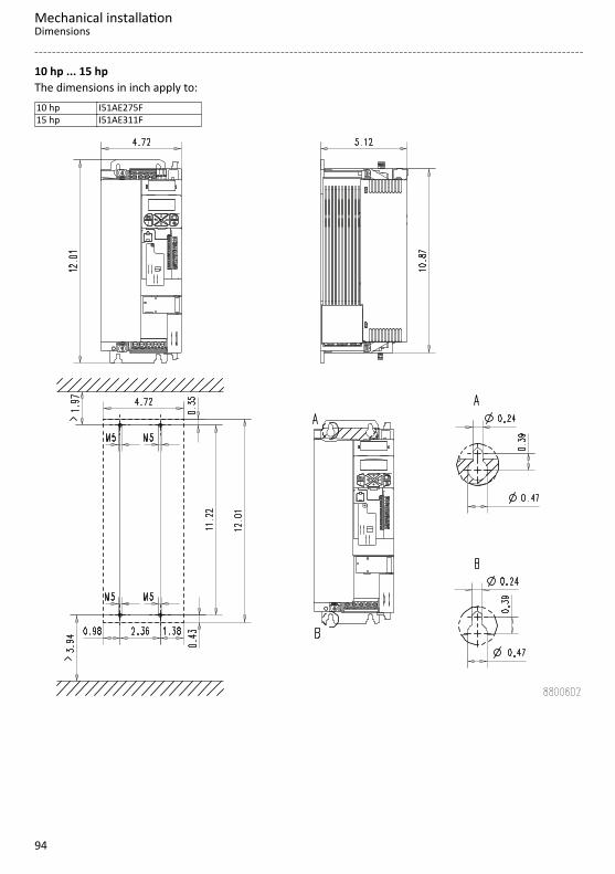
10 hp ... 15 hpThe dimensions in inch apply to:10 hp I51AE275F15 hp I51AE311F
Mechanical installationDimensions
94

Electrical installationImportant notes
DANGER!Electrical voltagePossible consequences: Death or severe injuries▶ Any work on the inverter must only be carried out in the deenergised state.▶ Inverter up to 45 kW: After switching off the mains voltage, wait for at least 3 min before you start
working.▶ Inverter from 55 kW onwards: After switching off the mains voltage, wait for at least 10 min before you
start working.
DANGER!Dangerous electrical voltageThe leakage current against earth (PE) is > 3.5 mA AC or > 10 mA DC.Possible consequences: Death or severe injuries when touching the device in the event of an error.▶ Implement the measures requested in EN 61800−5−1 or EN 60204−1. Especially:▶ Fixed installation▶ The PE connection must comply with the standards (PE conductor diameter ≥ 10 mm2 or use a double PE
conductor)
Electrical installationImportant notes
95

Connection according to UL
WARNING!▶ UL marking▶ The integral solid state short circuit protection included in the inverter does not provide branch circuit
protection. Branch circuit protection must be provided in accordance with the National Electrical Code /Canadian Electrical Code and any additional local codes.
▶ Marquage UL▶ La protection statique intégrée contre les courts-circuits n’offre pas la même protection que le dispositif
de protection du circuit de dérivation. Un tel dispositif doit être fourni, conformément au NationalElectrical Code / Canadian Electrical Code et aux autres dispositions applicables au niveau local.
NOTICE▶ UL marking▶ The opening of the Branch Circuit Protective Device may be an indication that a fault has been
interrupted. To reduce the risk of fire or electric shock, current-carring parts and other components of thecontroller should beexamined and replaced if damaged. If burnout of the current element of an overloadrelay occurs, the complete overload relay must be replaced.
▶ Marquage UL▶ Le déclenchement du dispositif de protection du circuit de dérivation peut être dû à une coupure qui
résulte d'un courant de défault. Pour limiter le risque d'incendie ou de choc électrique, examiner lespièces porteuses de courant et les autres éléments du contrôleur et les remplacer s'ils sont endommagés.En cas de grillage de l'élément traversé par le courant dans un relais de surcharge, le relais tout entier doitêtre remplacé.
NOTICE▶ UL marking▶ Internal overload protection rated for 125 % of the rated FLA.▶ Marquage UL▶ Protection contre les surcharges conçue pour se déclencher à 125 % de l'intensité assignée à pleine
charge.
WARNING!▶ UL marking▶ Use 75°C copper wire only, except for control circuits.▶ Marquage UL▶ Utiliser exclusivement des conducteurs en cuivre 75 °C, sauf pour la partie commande.
Electrical installationConnection according to UL
96

WARNING!▶ UL marking▶ Suitable for motor group installation or use on a circuit capable of delivering not more than the rms
symmetrical amperes (SCCR) of the drive at its rated voltage.▶ Approved fusing is specified in SCCR tables below.▶ Marquage UL▶ Convient pour l'utilisation sur une installation avec un groupe de moteurs ou sur un circuit capable de
fournir au maximum une valeur de courant efficace symétrique en ampères à la tension assignée del'appareil.
▶ Les dispositifs de protection adaptés sont spécifiés dans les SCCR tableaux suivants.
Electrical installationConnection according to UL
97

Branch Circuit Protection (BCP) with Short Circuit Current Ratings (SCCR) with Standard Fuses. (Tested perUL61800-5-1, reference UL file E132659)These devices are suitable for motor group installation when used with Standard Fuses. For single motorinstallation, if the fuse value indicated is higher than 400% of the motor current (FLA), the fuse value has tobe calculated. If the value of the fuse is below two standard ratings, the nearest standard ratings less thanthe calculated value shall apply.
Inverter Standard Fuses (UL248)
Mains kW hp SCCR Max. ratedcurrent Class
120 V, 1-ph 0.25 0.33 5 kA 15 A CC120 V, 1-ph 0.37 0.50 5 kA 15 A CC120 V, 1-ph 0.75 1.00 5 kA 30 A CC, J, T120 V, 1-ph 1.10 1.50 5 kA 30 A CC, J, T230 V, 1-ph 0.25 0.33 65 kA 15 A CC230 V, 1-ph 0.37 0.50 65 kA 15 A CC230 V, 1-ph 0.55 0.75 65 kA 15 A CC230 V, 1-ph 0.75 1.00 65 kA 15 A CC230 V, 1-ph 1.10 1.50 65 kA 30 A CC, J, T230 V, 1-ph 1.50 2.00 65 kA 30 A CC, J, T230 V, 1-ph 2.20 3.00 65 kA 30 A CC, J, T
230 V, 1/3-ph 0.25 0.33 65 kA 15 A CC230 V, 1/3-ph 0.37 0.50 65 kA 15 A CC230 V, 1/3-ph 0.55 0.75 65 kA 15 A CC230 V, 1/3-ph 0.75 1.00 65 kA 15 A CC230 V, 1/3-ph 1.10 1.50 65 kA 30 A CC, J, T230 V, 1/3-ph 1.50 2.00 65 kA 30 A CC, J, T230 V, 1/3-ph 2.20 3.00 65 kA 30 A CC, J, T230 V, 3-ph 4.00 5.00 100 kA 40 A J, T230 V, 3-ph 5.50 7.50 100 kA 40 A J, T480 V, 3-ph 0.37 0.50 65 kA 15 A CC480 V, 3-ph 0.55 0.75 65 kA 15 A CC480 V, 3-ph 0.75 1.00 65 kA 15 A CC480 V, 3-ph 1.1 1.5 65 kA 15 A CC480 V, 3-ph 1.5 2.0 65 kA 15 A CC480 V, 3-ph 2.2 3.0 65 kA 15 A CC480 V, 3-ph 3.0 4.0 65 kA 25 A CC, J, T480 V, 3-ph 4.0 5.0 65 kA 25 A CC, J, T480 V, 3-ph 5.5 7.5 65 kA 25 A CC, J, T480 V, 3-ph 7.5 10.0 65 kA 40 A J, T480 V, 3-ph 11.0 15.0 65 kA 40 A J, T480 V, 3-ph 15.0 20.0 100 kA 70 A J, T480 V, 3-ph 18.5 25.0 100 kA 70 A J, T480 V, 3-ph 22 30 100 kA 70 A J, T
480 V, 3-ph * 30 40 22 kA 125 A J, T480 V, 3-ph * 37 50 22 kA 125 A J, T480 V, 3-ph * 45 60 22 kA 125 A J, T480 V, 3-ph * 55 75 22 kA 200 A J, T480 V, 3-ph * 75 100 22 kA 200 A J, T480 V, 3-ph * 90 125 22 kA 300 A J, T480 V, 3-ph * 110 150 22 kA 300 A J, T
* Mains choke required
Electrical installationConnection according to UL
98

Branch Circuit Protection (BCP) with Short Circuit Current Rating (SCCR) for Semiconductor Fuses andCircuit Breaker. (Tested per UL61800-5-1, reference UL file E132659)These devices are suitable for motor group installation when used with Circuit Breakers. For single motorinstallation, if the fuse value indicated is higher than 400% of the motor current (FLA), the fuse value has tobe calculated. If the value of the fuse is below two standard ratings, the nearest standard ratings less thanthe calculated value shall apply.
Inverter Alternate Fuse (Semiconductor Fuse) Circuit Breaker (UL489)
Mains kW hp SCCR Fuse type SCCR Max. ratedcurrent
Min. cabinetdimensions
120 V, 1-ph 0.25 0.33
n/a
5 kA 15 A
n/a120 V, 1-ph 0.37 0.50 5 kA 15 A120 V, 1-ph 0.75 1.00 5 kA 30 A120 V, 1-ph 1.10 1.50 5 kA 30 A230 V, 1-ph 0.25 0.33 100 kA Mersen A60Q15-2 65 kA 15 A
0.042 m3
1.48 ft3
230 V, 1-ph 0.37 0.50 100 kA Mersen A60Q15-2 65 kA 15 A230 V, 1-ph 0.55 0.75 100 kA Mersen A70QS40-14F 65 kA 15 A230 V, 1-ph 0.75 1.00 100 kA Mersen A70QS40-14F 65 kA 15 A230 V, 1-ph 1.10 1.50 100 kA Mersen A70QS40-14F 65 kA 30 A230 V, 1-ph 1.50 2.00 100 kA Mersen A70QS40-14F 65 kA 30 A230 V, 1-ph 2.20 3.00 100 kA Mersen A70QS40-14F 65 kA 30 A
230 V, 1/3-ph 0.25 0.33 100 kA Mersen A60Q15-2 65 kA 15 A
0.042 m3
1.48 ft3
230 V, 1/3-ph 0.37 0.50 100 kA Mersen A60Q15-2 65 kA 15 A230 V, 1/3-ph 0.55 0.75 100 kA Mersen A70QS40-14F 65 kA 15 A230 V, 1/3-ph 0.75 1.00 100 kA Mersen A70QS40-14F 65 kA 15 A230 V, 1/3-ph 1.10 1.50 100 kA Mersen A70QS40-14F 65 kA 30 A230 V, 1/3-ph 1.50 2.00 100 kA Mersen A70QS40-14F 65 kA 30 A230 V, 1/3-ph 2.20 3.00 100 kA Mersen A70QS40-14F 65 kA 30 A230 V, 3-ph 4.00 5.00 100 kA Mersen A70QS50-22F 65 kA 40 A 0.042 m3
1.48 ft3230 V, 3-ph 5.50 7.50 100 kA Mersen A70QS50-22F 65 kA 40 A480 V, 3-ph 0.37 0.50 100 kA Mersen A70QS6-14F 65 kA 15 A
0.042 m3
1.48 ft3
480 V, 3-ph 0.55 0.75 100 kA Mersen A60Q15-2 65 kA 15 A480 V, 3-ph 0.75 1.00 100 kA Mersen A60Q15-2 65 kA 15 A480 V, 3-ph 1.1 1.5 100 kA Mersen A60Q15-2 65 kA 15 A480 V, 3-ph 1.5 2.0 100 kA Mersen A60Q15-2 65 kA 15 A480 V, 3-ph 2.2 3.0 100 kA Mersen A60Q15-2 65 kA 15 A
480 V, 3-ph480 V, 3-ph
3.04.0
4.05.0 100 kA
Mersen A70QS40-14FMersen A70QS40-22F
Mersen A70QS40-4Eaton/Bussmann FWP-50A14FaEaton/Bussmann FWP-50A22F
Eaton/Bussmann FWP-50BLittlefuse L70QS050
65 kA 25 A 0.042 m3
1.48 ft3
480 V, 3-ph 5.5 7.5 100 kA Mersen A70QS40-14F 65 kA 25 A 0.042 m3
1.48 ft3480 V, 3-ph 7.5 10.0 100 kA Mersen A70QS50-22F 65 kA 40 A480 V, 3-ph 11.0 15.0 100 kA Mersen A70QS50-22F 65 kA 40 A480 V, 3-ph 15.0 20.0 100 kA Mersen A70QS80-22F 65 kA 60 A 0.17 m3
6 ft3480 V, 3-ph 18.5 25.0 100 kA Mersen A70QS80-22F 65 kA 60 A480 V, 3-ph 22 30 100 kA Mersen A70QS80-22F 65 kA 60 A
480 V, 3-ph * 30 40 100 kA Mersen A70QS80-4 35 kA 125 A
0.57 m3
20 ft3
480 V, 3-ph * 37 50 100 kA Mersen A70QS100-4 35 kA 125 A480 V, 3-ph * 45 60 100 kA Mersen A70QS125-4 35 kA 125 A480 V, 3-ph * 55 75 100 kA Mersen A70QS200-4 35 kA 200 A480 V, 3-ph * 75 100 100 kA Mersen A70QS200-4 35 kA 200 A
480 V, 3-ph * 90 125 100 kA Eaton FWP-350AMersen A70QS350-4 10 kA 300 A
480 V, 3-ph * 110 150 100 kA Eaton FWP-350AMersen A70QS350-4 10 kA 300 A
* Mains choke required
Electrical installationConnection according to UL
99

Mains connection
1-phase mains connection 230/240 V
Connection diagramsThe connection plan is valid for the inverters I51AExxxB.
CL/
TA
CG
/COM
CH
/TB
X21
6
CANopen/Modbus
Modbus
CHTB CLTA CGCO
M
1k ...
10k
0 ...
10
V
S1
"
100 mA
+24 V
Basic I/O
GND
DO
1
4.4k
DI1
4.
4k D
I2
4.4k
DI3
4.
4k D
I4
4.4k
DI5
AI1
A
I2
+10 V
10 m
A 1
0V
GND
AO
1
24V
X3
X10
5 U
V
W
+
"
M3~+
JJ
NC
NO
COM
X
9
AC 240 V3 A
F1…F3Q1
X10
0 L1
L2/N
2/PE AC 170 V ... 264 V45 Hz ... 65 Hz
+
2/PE AC 170 V ... 264 V45 Hz ... 65 Hz
+
F1…F2Q1
X10
0 L1
L2/N
X10
0 L1
L2/N
F1
Q1
PEN
L2L1
2/N/PE AC 208 V ... 240 V
PEN
L3L2L1
3/N/PE AC 208 V ... 240 V
PEN
L3L2L1
+
1/N/PEAC 170 V ... 264 V45 Hz ... 65 Hz
3/N/PE AC 400 V
Fig. 7: Wiring exampleS1 Start/StopFx Fuses
Q1 Mains contactor--- Dashed line = options
Electrical installationMains connection1-phase mains connection 230/240 V
100

The connection plan is valid for the inverters I51AExxxD.
Inverters I51AExxxD do not have an integrated RFI filter in the AC mains supply.In order to meet the EMC requirements according to EN 61800−3, an external EMC filter accordingto IEC EN 60939 must be used.The user must verify that the conformity with EN 61800−3 is fulfilled.
/
CL
TA
/
CG
COM
/
CH
TB X21
6
CANopen/Modbus
Modbus
CHTB CLTA CGCO
M
1k ...
10k
0 ...
10
V
S1
"
100 mA
+24 V
Basic I/O
GND
1
DO
4.4k
1
DI4.
4k
2 DI
4.4k
3
DI4.
4k
4 DI
4.4k
5
DI 1
AI 2
AI
+10 V
10 m
A 1
0V
GND
1
AO 24V
X3
X10
5 U
V
W
+
"
M3~+
JJ
NC
NO
COM X9
AC 240 V3 A
2/ PE 170 V ... 264 VAC
45 Hz ... 65 Hz+
F1…F2Q1
X10
0 L1
L2/N
L3
X10
0 L1
L2/N
L3
F1
Q1
PEN
L3L2L1
3/N/ PE 208 V ... 240 VAC
PEN
L3L2L1
+
1/N/PE 170 V ... 264 VAC
45 Hz ... 65 Hz
3/N/ PE 400 VAC
Fig. 8: Wiring exampleS1 Start/StopFx Fuses
Q1 Mains contactor--- Dashed line = options
Electrical installationMains connection
1-phase mains connection 230/240 V
101

Terminal dataInverter I51AExxxxInverter kW 0.25 ... 0.75 1.1 ... 2.2 0.25 ... 2.2 0.25 ... 2.2Connection Mains connection X100 PE connection Motor connection
X105 Connection type Pluggable screw terminal PE screw Pluggable screw
terminal Max. cable cross-section mm² 2.5 6 6 2.5 Stripping length mm 8 8 10 8 Tightening torque Nm 0.5 0.7 2 0.5 Required tool 0.5 x 3.0 0.6 x 3.5 Torx 20 0.5 x 3.0
Fusing data
EN 60204-1Inverter Fuse Circuit breaker Earth-leakage circuit
breakerCharacteristic Max. rated
currentCharacteristic Max. rated
current A A
I51AE125B gG/gL or gRL 10 B 10 ≥ 30 mA, type A or BI51AE125D gG/gL or gRL 10 B 10 ≥ 30 mA, type A or BI51AE137B gG/gL or gRL 10 B 10 ≥ 30 mA, type A or BI51AE137D gG/gL or gRL 10 B 10 ≥ 30 mA, type A or BI51AE155B gG/gL or gRL 16 B 16 ≥ 30 mA, type A or BI51AE155D gG/gL or gRL 16 B 16 ≥ 30 mA, type A or BI51AE175B gG/gL or gRL 16 B 16 ≥ 30 mA, type A or BI51AE175D gG/gL or gRL 16 B 16 ≥ 30 mA, type A or BI51AE211B gG/gL or gRL 25 B 25 ≥ 30 mA, type A or BI51AE211D gG/gL or gRL 25 B 25 ≥ 30 mA, type A or BI51AE215B gG/gL or gRL 25 B 25 ≥ 30 mA, type A or BI51AE215D gG/gL or gRL 25 B 25 ≥ 30 mA, type A or BI51AE222B gG/gL or gRL 25 B 25 ≥ 30 mA, type A or BI51AE222D gG/gL or gRL 25 B 25 ≥ 30 mA, type A or B
Electrical installationMains connection1-phase mains connection 230/240 V
102

3-phase mains connection 230/240 V
Connection diagramsThe connection plan is valid for the inverter I51AExxxC.
The I51AExxxC inverter does not have an integrated RFI filter in the AC mains supply.In order to meet the EMC requirements according to EN 61800−3, an external EMC filter accordingto IEC EN 60939 must be used.The user must verify that the conformity with EN 61800−3 is fulfilled.
/
CL
TA
/
CG
COM
/
CH
TB X21
6
CANopen/Modbus
Modbus
CHTB CLTA CGCO
M
1k ...
10k
0 ...
10
V
S1
"
100 mA
+24 V
Basic I/O
GND
1
DO
4.4k
1
DI4.
4k
2 DI
4.4k
3
DI4.
4k
4 DI
4.4k
5
DI 1
AI 2
AI
+10 V
10 m
A 1
0V
GND
1
AO 24V
X3
X10
5 U
V
W
+
"
M3~+
JJ
NC
NO
COM X9
AC 240 V3 A
X10
0 L1
L2
L3
F1…F3Q1
3/N/ PE 208 V ... 240 VAC
3/ PE 170 V ... 264 VAC
45 Hz ... 65 Hz
PEN
L3L2L1
+
Fig. 9: Wiring exampleS1 Start/StopFx Fuses
Q1 Mains contactor--- Dashed line = options
Electrical installationMains connection
3-phase mains connection 230/240 V
103

The connection plan is valid for the I51AExxxD inverter.
The I51AExxxD inverter does not have an integrated RFI filter in the AC mains supply.In order to meet the EMC requirements according to EN 61800−3, an external EMC filter accordingto IEC EN 60939 must be used.The user must verify that the conformity with EN 61800−3 is fulfilled.
/
CL
TA
/
CG
COM
/
CH
TB X21
6
CANopen/Modbus
Modbus
CHTB CLTA CGCO
M
1k ...
10k
0 ...
10
V
S1
"
100 mA
+24 V
Basic I/O
GND
1
DO
4.4k
1
DI4.
4k
2 DI
4.4k
3
DI4.
4k
4 DI
4.4k
5
DI 1
AI 2
AI
+10 V
10 m
A 1
0V
GND
1
AO 24V
X3
X10
5 U
V
W
+
"
M3~+
JJ
NC
NO
COM X9
AC 240 V3 A
X10
0 L1
L2/N
L3
F1…F3Q1
3/N/ PE 208 V ... 240 VAC
3/ PE 170 V ... 264 VAC
45 Hz ... 65 Hz
PEN
L3L2L1
+
Fig. 10: Wiring exampleS1 Start/StopFx Fuses
Q1 Mains contactor--- Dashed line = options
Electrical installationMains connection3-phase mains connection 230/240 V
104

Terminal dataInverter I51AExxxxInverter kW 0.25 ... 0.75 1.1 ... 2.2 4.0 ... 5.5 0.25 ... 5.5 0.25 ... 2.2 4.0 ... 5.5Connection Mains connection X100 PE connection Motor connection X105 Connection type Pluggable screw terminal Screw
terminalPE screw Pluggable
screwterminal
Screwterminal
Max. cable cross-section mm² 2.5 6 6 6 2.5 6 Stripping length mm 8 8 9 10 8 9 Tightening torque Nm 0.5 0.7 0.5 2 0.5 0.5 Required tool 0.5 x 3.0 0.6 x 3.5 Torx 20 0.5 x 3.0 0.6 x 3.5
Fusing data
EN 60204-1Inverter Fuse Circuit breaker Earth-leakage circuit
breakerCharacteristic Max. rated
currentCharacteristic Max. rated
current A A
I51AE125D gG/gL or gRL 10 B 10 ≥ 30 mA, type BI51AE137D gG/gL or gRL 10 B 10 ≥ 30 mA, type BI51AE155D gG/gL or gRL 16 B 16 ≥ 30 mA, type BI51AE175D gG/gL or gRL 16 B 16 ≥ 30 mA, type BI51AE211D gG/gL or gRL 25 B 25 ≥ 30 mA, type BI51AE215D gG/gL or gRL 25 B 25 ≥ 30 mA, type BI51AE222D gG/gL or gRL 25 B 25 ≥ 30 mA, type BI51AE240C gG/gL or gRL 32 B 32 ≥ 300 mA, type BI51AE255C gG/gL or gRL 32 B 32 ≥ 300 mA, type B
3-phase mains connection 230/240 V "Light Duty"
Connection diagramsSee "3-phase mains connection 230/240 V". ^ 103
Terminal dataInverter I51AExxxxInverter kW 5.5 ... 7.5 5.5 ... 7.5 5.5 ... 7.5Connection Mains connection X100 PE connection Motor connection X105 Connection type Screw terminal PE screw Screw terminal Max. cable cross-section mm² 6 6 6 Stripping length mm 9 10 9 Tightening torque Nm 0.5 2 0.5 Required tool 0.6 x 3.5 Torx 20 0.6 x 3.5
Fusing data
EN 60204-1Inverter Fuse Circuit breaker Earth-leakage circuit
breakerCharacteristic Max. rated
currentCharacteristic Max. rated
current A A
I51AE240C gG/gL or gRL 32 B 32 ≥ 300 mA, type BI51AE255C gG/gL or gRL 32 B 32 ≥ 300 mA, type B
Electrical installationMains connection
3-phase mains connection 230/240 V "Light Duty"
105

3-phase mains connection 400 V
Connection diagramsThe connection plan is valid for the inverter I51AExxxF and I51BExxxF .
+
PEN
L3L2L1
CL/
TA
CG
/COM
CH
/TB
X21
6 CANopen/Modbus
Modbus
CHTB CLTA CGCO
M
1k ...
10k
0 ...
10
V
S1
"
100 mA
+24 V
Basic I/O
GND
DO
1
4.4k
DI1
4.
4k D
I2
4.4k
DI3
4.
4k D
I4
4.4k
DI5
AI1
A
I2
+10 V
10 m
A 1
0V
GND
AO
1
24V
X3
X10
5 U
V
W
+
"
M3~+
JJ
NC
NO
COM
X
9
AC 240 V3 A
X10
0 L1
L2
L3
F1…F3Q1
3/N/PE AC 400 V
3/PE AC 340 V ... 528 V45 Hz ... 65 Hz
Fig. 11: Wiring exampleS1 Start/StopFx Fuses
Q1 Mains contactor--- Dashed line = options
Electrical installationMains connection3-phase mains connection 400 V
106

Terminal dataInverter I51AExxxFInverter kW 0.37 ... 2.2 3.0 ... 4.0 5.5 7.5 ... 11 0.37 ... 5.5 3.0 ... 4.0Connection Mains connection X100 PE connection Connection type Pluggable
screwterminal
Screw terminal PE screw
Max. cable cross-section mm² 2.5 6 6 16 6 6 Stripping length mm 8 9 9 11 10 10 Tightening torque Nm 0.5 0.5 0.5 1.2 2 2 Required tool 0.5 x 3.0 0.6 x 3.5 0.8 x 4.0 Torx 20
Inverter I51AExxxFInverter kW 7.5 ... 11 0.37 ... 2.2 3.0 ... 4.0 5.5 7.5 ... 11Connection PE connection Motor connection X105 Connection type PE screw Pluggable screw
terminalScrew terminal
Max. cable cross-section mm² 16 2.5 6 6 16 Stripping length mm 11 8 9 9 11 Tightening torque Nm 3.4 0.5 0.5 0.5 1.2 Required tool PZ2 0.5 x 3.0 0.6 x 3.5 0.8 x 4.0
Inverter I51BExxxFInverter kW 3.0 ... 4.0 3.0 ... 4.0 3.0 ... 4.0Connection Mains connection X100 PE connection Motor connection X105 Connection type Pluggable screw terminal PE screw Pluggable screw terminal Max. cable cross-section mm² 4 6 2.5 Stripping length mm 8 10 8 Tightening torque Nm 0.6 2 0.5 Required tool 0.5 x 3.0 Torx 20 0.5 x 3.0
Fusing data
EN 60204-1Inverter Fuse Circuit breaker Earth-leakage circuit
breakerCharacteristic Max. rated
currentCharacteristic Max. rated
current A A
I51AE137F gG/gL or gRL 10 B 10 ≥ 30 mA, type BI51AE155F gG/gL or gRL 10 B 10 ≥ 30 mA, type BI51AE175F gG/gL or gRL 10 B 10 ≥ 30 mA, type BI51AE211F gG/gL or gRL 16 B 16 ≥ 30 mA, type BI51AE215F gG/gL or gRL 16 B 16 ≥ 30 mA, type BI51AE222F gG/gL or gRL 16 B 16 ≥ 30 mA, type BI51AE230F gG/gL or gRL 25 B 25 ≥ 300 mA, type BI51BE230F gG/gL or gRL 25 B 25 ≥ 30 mA, type BI51AE240F gG/gL or gRL 25 B 25 ≥ 300 mA, type BI51BE240F gG/gL or gRL 25 B 25 ≥ 30 mA, type BI51AE255F gG/gL or gRL 25 B 25 ≥ 300 mA, type BI51AE275F gG/gL or gRL 32 B 32 ≥ 300 mA, type BI51AE311F gG/gL or gRL 32 B 32 ≥ 300 mA, type B
Electrical installationMains connection
3-phase mains connection 400 V
107

3-phase mains connection 400 V "Light Duty"
Connection diagramsSee "3-phase mains connection 400 V". ^ 106
Terminal dataSee "Terminal data". ^ 107
Fusing data
EN 60204-1Inverter Fuse Circuit breaker Earth-leakage circuit
breakerCharacteristic Max. rated
currentCharacteristic Max. rated
current A A
I51AE230F gG/gL or gRL 25 B 25 ≥ 300 mA, type BI51BE230F gG/gL or gRL 25 B 25 ≥ 30 mA, type BI51AE240F gG/gL or gRL 25 B 25 ≥ 300 mA, type BI51BE240F gG/gL or gRL 25 B 25 ≥ 30 mA, type BI51AE255F gG/gL or gRL 25 B 25 ≥ 300 mA, type BI51AE275F gG/gL or gRL 32 B 32 ≥ 300 mA, type BI51AE311F gG/gL or gRL 32 B 32 ≥ 300 mA, type B
Electrical installationMains connection3-phase mains connection 400 V "Light Duty"
108

3-phase mains connection 480 V
Connection diagramsThe connection plan is valid for the inverters I51AExxxF.
+
PEN
L3L2L1
CL/
TA
CG
/COM
CH
/TB
X21
6 CANopen/Modbus
Modbus
CHTB CLTA CGCO
M
1k ...
10k
0 ...
10
V
S1
"
100 mA
+24 V
Basic I/O
GND
DO
1
4.4k
DI1
4.
4k D
I2
4.4k
DI3
4.
4k D
I4
4.4k
DI5
AI1
A
I2
+10 V
10 m
A 1
0V
GND
AO
1
24V
X3
X10
5 U
V
W
+
"
M3~+
JJ
NC
NO
COM
X
9
AC 240 V3 A
X10
0 L1
L2
L3
F1…F3Q1
3/N/PE AC 480 V
3/PE AC 340 V ... 528 V45 Hz ... 65 Hz
Fig. 12: Wiring exampleS1 Start/StopFx Fuses
Q1 Mains contactor--- Dashed line = options
Terminal dataSee "Terminal data". ^ 107
Electrical installationMains connection
3-phase mains connection 480 V
109

Fusing data
EN 60204-1Inverter Fuse Circuit breaker Earth-leakage circuit
breakerCharacteristic Max. rated
currentCharacteristic Max. rated
current A A
I51AE137F gG/gL or gRL 10 B 10 ≥ 30 mA, type BI51AE155F gG/gL or gRL 10 B 10 ≥ 30 mA, type BI51AE175F gG/gL or gRL 10 B 10 ≥ 30 mA, type BI51AE211F gG/gL or gRL 16 B 16 ≥ 30 mA, type BI51AE215F gG/gL or gRL 16 B 16 ≥ 30 mA, type BI51AE222F gG/gL or gRL 16 B 16 ≥ 30 mA, type BI51AE230F gG/gL or gRL 25 B 25 ≥ 300 mA, type BI51BE230F gG/gL or gRL 25 B 25 ≥ 30 mA, type BI51AE240F gG/gL or gRL 25 B 25 ≥ 300 mA, type BI51BE240F gG/gL or gRL 25 B 25 ≥ 30 mA, type BI51AE255F gG/gL or gRL 25 B 25 ≥ 300 mA, type BI51AE275F gG/gL or gRL 32 B 32 ≥ 300 mA, type BI51AE311F gG/gL or gRL 32 B 32 ≥ 300 mA, type B
3-phase mains connection 480 V "Light Duty"
Connection diagramsSee "3-phase mains connection 480 V". ^ 109
Terminal dataSee "Terminal data". ^ 107
Fusing data
EN 60204-1Inverter Fuse Circuit breaker Earth-leakage circuit
breakerCharacteristic Max. rated
currentCharacteristic Max. rated
current A A
I51AE230F gG/gL or gRL 25 B 25 ≥ 300 mA, type BI51BE230F gG/gL or gRL 25 B 25 ≥ 30 mA, type BI51AE240F gG/gL or gRL 25 B 25 ≥ 300 mA, type BI51BE240F gG/gL or gRL 25 B 25 ≥ 30 mA, type BI51AE255F gG/gL or gRL 25 B 25 ≥ 300 mA, type BI51AE275F gG/gL or gRL 32 B 32 ≥ 300 mA, type BI51AE311F gG/gL or gRL 32 B 32 ≥ 300 mA, type B
Electrical installationMains connection3-phase mains connection 480 V "Light Duty"
110

Connection to the IT system
For a trouble-free operation on the IT system, observe the following measures:• Connect an isolating transformer upstream.• Remove the IT screws. Otherwise the monitoring devices of the IT system will be triggered because
internal components are connected to protective earth (PE).
I51AE125x, I51AE137x I51AE155x, I51AE175x, I51AE211x, I51AE215x, I51AE222x,I51BE230F, I51BE240F
TX10
TX10
TX10
Electrical installationConnection to the IT system
111

I51AE230x, I51AE240x, I51AE255x, I51AE275x, I51AE311x
TX10
TX10
Control connectionsConnection description Control terminalsConnection X3 Connection type Spring terminal Max. cable cross-section mm² 1.5 Max. cable cross-section AWG 16 Stripping length mm 9 Stripping length inch 0.35 Tightening torque Nm - Tightening torque lb-in - Required tool 0.4 x 2.5
Electrical installationControl connections
112

Networks
CANopen/Modbus
The network must be terminated with a 120 Ω resistor at the physically first and last node.Connect resistor to terminals CH/TB and CL/TA.
Typical topologiesLine
A1 A2 A3 An
X216 X216 X216 X216
120120
CG
/
CO
M
CL/
TA
CH
/
TB
CG
/
CO
M
CL/
TA
CH
/
TB
CG
/
CO
M
CL/
TA
CH
/
TB
CG
/
CO
M
CL/
TA
CH
/
TB
Connection description CANopen/ModbusConnection X216 Connection type pluggable double spring terminal Max. cable cross-section mm² 2.5 Max. cable cross-section AWG 12 Stripping length mm 10 Stripping length inch 0.39 Tightening torque Nm - Tightening torque lb-in - Required tool 0.4 x 2.5
Basic network settings1. Select network CANopen or Modbus using the switch on the front of the inverter.
CANopenModbus
2. Set node address and baud rate via the corresponding parameters.
Electrical installationNetworks
CANopen/Modbus
113

BACnetTypical topologies
Line
A1 A2 A3 An
X216 X216 X216 X216
120120
CG
/
CO
M
CL/
TA
CH
/
TB
CG
/
CO
M
CL/
TA
CH
/
TB
CG
/
CO
M
CL/
TA
CH
/
TB
CG
/
CO
M
CL/
TA
CH
/
TB
Connection description BACnet MS/TPConnection X216 Connection type pluggable double spring terminal Max. cable cross-section mm² 2.5 Max. cable cross-section AWG 12 Stripping length mm 10 Stripping length inch 0.39 Tightening torque Nm - Tightening torque lb-in - Required tool 0.4 x 2.5
Basic network settings1. Select network BACnet using the switch on the front of the inverter.
BACnet
2. Set node address and baud rate via the corresponding parameters.
Electrical installationNetworksBACnet
114

CommissioningThe purpose of commissioning is to adapt the inverter as part of a machine with a variable-speed drivesystem to its drive task.
Important notes
DANGER!Incorrect wiring can cause unexpected states during the commissioning phase.Possible consequences: death, severe injuries or damage to propertyEnsure the following before switching on the mains voltage:▶ Wiring must be complete and correct.▶ Wiring must be free of short circuits and earth faults.▶ The motor circuit configuration (star/delta) must be adapted to the inverter output voltage.▶ The motor must be connected in-phase (direction of rotation).▶ The "emergency off" function of the overall system must operate correctly.
CommissioningImportant notes
115

Initial switch-on and functional test
Target: achieve rotation of the motor connected to the inverter as quickly as possible.Requirements:• The connected motor matches the inverter in terms of power.• The parameter settings comply with the delivery status (Lenze setting).1. Preparation
1. Wire power terminals. 2. Wire digital inputs X3/DI1 (start/stop), X3/DI3 (reversal) and X3/DI4 (frequency preset 20 Hz).3. Do not connect terminal X3/AI1 (analog setpoint selection) or connect it to GND.
Start/
Stop
DI1
DI3
DI4
24
V
X3
20 Hz
2. Switch on mains and check readiness for operation1. Switch on mains voltage.2. Observe LED status displays "RDY" and "ERR" on the front of the inverter:
a) If the blue "RDY" LED is blinking and the red "ERR" LED is off, the inverter is ready for operation. Thecontroller is inhibited.You can now start the drive.
b) If the red "ERR" LED is lit permanently, a fault is pending.Eliminate the fault before you carry on with the functional test.
LED status displays"RDY" LED (blue) "ERR" LED (red) Status/meaningoff off No supply voltage.blinking (1 Hz) off Safe torque off (STO) active.
blinking fast (4 Hz) Safe torque off (STO) active. Warning active.blinking (2 Hz) off Inverter inhibited.
lit every 1.5 s for ashort time
Inverter inhibited, no DC-bus voltage.
blinking fast (4 Hz) Inverter inhibited, warning active.on Inverter inhibited, fault active.
on off Inverter enabled. The motor rotates according to thesetpoint specified or quick stop active.blinking fast (4 Hz) Inverter enabled, warning active.
blinking (1 Hz) Inverter enabled, quick stop as response to a fault active.
CommissioningInitial switch-on and functional test
116

Carry out functional test1. Start drive
1. Start inverter: X3/DI1 = HIGH.2. Activate frequency preset 1 (20 Hz) as speed setpoint: X3/DI4 = HIGH.
The drive rotates with 20 Hz.3. Optional: activate the function for the reversal of rotation direction.
a) X3/DI3 = HIGH.The drive rotates at 20 Hz in the opposite direction.
b) Deactivate the function for the reversal of rotation direction again: X3/DI3 = LOW.Speed characteristic (example)
t0
50
60
20
5 s 5 s-20
t
DI3 t
DI4t
AI1 [V]
0
10
t
DI1 Drive follows frequency setpoint
Speed setpoint selection via X3/ 1 activeAI(In this example X3/ 1 is connected to )AI GND
Preset frequency setpoint 1 (20 Hz)
Invert rotation active
f [Hz]set
Preset frequency setpoint 1 active
2. Stop drive1. Deactivate frequency preset 1 again: X3/DI4 = LOW.2. Stop inverter again: X3/DI1 = LOW.
The functional test has been completed.
CommissioningInitial switch-on and functional test
117

Technical dataStandards and operating conditions
Conformities/approvalsConformity
CE 2014/35/EU Low-Voltage Directive2014/30/EU EMC Directive (reference: CE-typical drive system)
EACTR CU 004/2011 Eurasian conformity: safety of low voltage equipment
TR CU 020/2011 Eurasian conformity: electromagnetic compatibility oftechnical means
RoHS 2011/65/EU Restrictions on the use of certain hazardous substances inelectrical and electronic devices
Approval
UL UL 61800-5-1for USA and Canada (requirements of the CSA 22.2 No.274)
File No. E132659
Protection of persons and device protectionDegree of protection
IP20 EN 60529 Data applies for operationally ready mounted state and notin wire range of terminals
UL 50 Protection against accidental contact only Open type Only in UL-approved systemsInsulation resistance Overvoltage category III EN 61800-5-1 0 … 2000 m amsl Overvoltage category II EN 61800-5-1 over 2000 m amslIsolation of control circuits
Safe mains isolation via double/reinforcedinsulation EN 61800-5-1
Leakage current > 3.5 mA AC, > 10 mA DC EN 61800-5-1 Please observe regulations and safety instructions!Starting current ≤ 3 x rated mains current Protective measures against Short circuit Earth fault Earth-fault protected depending on operating status Overtemperature of motor I²xt monitoring Overvoltage Motor stalling
EMC dataNoise emission Category C2 EN 61800-3 See rated data Category C3 EN 61800-3 See rated dataNoise immunity Fulfills requirements according to EN 61800-3 Operation on public supply systems
Take measures to limit the expected radiointerference: The machine or system manufacturer is responsible for
compliance with the requirements for the machine/system!
< 1 kW: With mains choke
EN 61000-3-2 > 1 kW for mains current ≤ 16 A: Withoutadditional measures
Mains current > 16 A: with mains chokeor mains filter, with dimensioning forrated power.
EN 61000-3-12
Technical dataEMC data
118

Motor connectionRequirements for the shielded motor cable Capacitance per unit length
C-core-core/C-core-shielding < 75/150pF/m
≤ 2.5 mm² / AWG 14
C-core-core/C-core-shielding < 150/300pF/m ≥ 4 mm² / AWG 12
Electric strength
Uo/U = 0.6/1.0 kV Uo = r.m.s. value external conductor to PEU = r.m.s. value from external conductor to externalconductor
U ≥ 600 V UL U = r.m.s. value from external conductor to externalconductor
Environmental conditionsEnergy efficiency Class IE2 EN 50598-2 Climate 1K3 (-25 ... +60°C) EN 60721-3-1 Storage 2K3 (-25 ... +70°C) EN 60721-3-2 Transport 3K3 (-10 ... +55°C) EN 60721-3-3 Operation
Operation at a switching frequency of 2 or 4 kHz: above+45°C, reduce rated output current by 2.5 %/°C
Operation at a switching frequency of 8 or 16 kHz: above+40°C reduce rated output current by 2.5 %/°C
Site altitude 0 … 1000 m amsl 1000 … 4000 m amsl Reduce rated output current by 5 %/1000 mPollution Degree of pollution 2 EN 61800-5-1 UL 61800-5-1Vibration resistance Transport 2M2 (sine, shock) EN 60721-3-2 In original packaging Operation
Amplitude 1 mm Germanischer Lloyd 5 ... 13.2 HzAcceleration resistant up to 0.7 g 13.2 ... 100 Hz
Amplitude 0.075 mm EN 61800-5-1 10 ... 57 Hz Acceleration resistant up to 1 g 57 ... 150 Hz
Electrical supply conditionsPermissible power systems TT Voltage to earth: max. 300 V TN Voltage to earth: max. 300 V IT Please employ the measures described for IT systems! IT systems not relevant for UL-approved systems
Technical dataStandards and operating conditions
Electrical supply conditions
119

1-phase mains connection 230/240 V
Rated dataThe output currents apply to these operating conditions:• At a switching frequency of 2 kHz or 4 kHz: Max. ambient temperature 45°C.• At a switching frequency of 8 kHz or 16 kHz: Max. ambient temperature 40 °C.Inverter I51AE125B I51AE125D I51AE137B I51AE137D I51AE155B I51AE155DRated power kW 0.25 0.25 0.37 0.37 0.55 0.55Rated power hp 0.33 0.33 0.5 0.5 0.75 0.75Mains voltage range 1/PE AC 170 V ... 264 V, 45 Hz ... 65 HzOutput voltage 3 AC 0-230/240 VRated mains current Without mains choke A 4 4 5.7 5.7 7.6 7.6 With mains choke A 3.6 3.6 4.8 4.8 7.1 7.1Apparent output power kVA 0.6 0.6 0.9 0.9 1.2 1.2Rated output current 2 kHz A - - - - 3.2 3.2 4 kHz A 1.7 1.7 2.4 2.4 3.2 3.2 8 kHz A 1.7 1.7 2.4 2.4 3.2 3.2 16 kHz A 1.1 1.1 1.6 1.6 2.1 2.1Power loss 2 kHz W - - - - 22 22 4 kHz W 15 15 18 18 23 23 8 kHz W 15 15 20 20 25 25 16 kHz W 19 19 24 24 30 30 For controller inhibit W 6 6 6 6 6 6Cyclic mains switching 3 times per minuteMax. motor cable lengthshielded
Category C2 (2 kHz, 4 kHz, 8kHz)
m 15 - 15 - 20 -
Category C3 (2 kHz, 4 kHz, 8kHz)
m 15 - 15 - 50 -
Without EMC category m 50 50 50 50 50 50Weight kg 0.75 0.75 0.75 0.75 0.95 0.95Weight lb 1.7 1.7 1.7 1.7 2.1 2.1
Technical data1-phase mains connection 230/240 VRated data
120
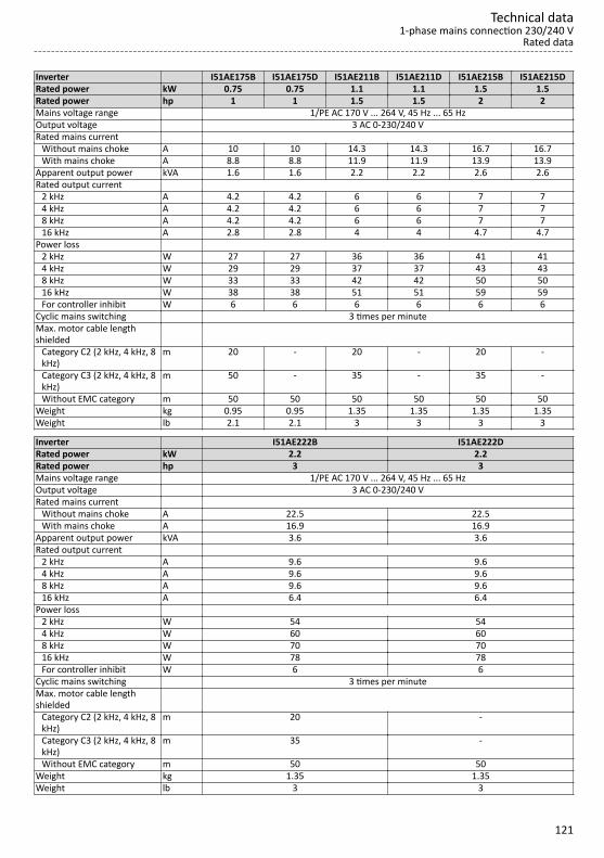
Inverter I51AE175B I51AE175D I51AE211B I51AE211D I51AE215B I51AE215DRated power kW 0.75 0.75 1.1 1.1 1.5 1.5Rated power hp 1 1 1.5 1.5 2 2Mains voltage range 1/PE AC 170 V ... 264 V, 45 Hz ... 65 HzOutput voltage 3 AC 0-230/240 VRated mains current Without mains choke A 10 10 14.3 14.3 16.7 16.7 With mains choke A 8.8 8.8 11.9 11.9 13.9 13.9Apparent output power kVA 1.6 1.6 2.2 2.2 2.6 2.6Rated output current 2 kHz A 4.2 4.2 6 6 7 7 4 kHz A 4.2 4.2 6 6 7 7 8 kHz A 4.2 4.2 6 6 7 7 16 kHz A 2.8 2.8 4 4 4.7 4.7Power loss 2 kHz W 27 27 36 36 41 41 4 kHz W 29 29 37 37 43 43 8 kHz W 33 33 42 42 50 50 16 kHz W 38 38 51 51 59 59 For controller inhibit W 6 6 6 6 6 6Cyclic mains switching 3 times per minuteMax. motor cable lengthshielded
Category C2 (2 kHz, 4 kHz, 8kHz)
m 20 - 20 - 20 -
Category C3 (2 kHz, 4 kHz, 8kHz)
m 50 - 35 - 35 -
Without EMC category m 50 50 50 50 50 50Weight kg 0.95 0.95 1.35 1.35 1.35 1.35Weight lb 2.1 2.1 3 3 3 3
Inverter I51AE222B I51AE222DRated power kW 2.2 2.2Rated power hp 3 3Mains voltage range 1/PE AC 170 V ... 264 V, 45 Hz ... 65 HzOutput voltage 3 AC 0-230/240 VRated mains current Without mains choke A 22.5 22.5 With mains choke A 16.9 16.9Apparent output power kVA 3.6 3.6Rated output current 2 kHz A 9.6 9.6 4 kHz A 9.6 9.6 8 kHz A 9.6 9.6 16 kHz A 6.4 6.4Power loss 2 kHz W 54 54 4 kHz W 60 60 8 kHz W 70 70 16 kHz W 78 78 For controller inhibit W 6 6Cyclic mains switching 3 times per minuteMax. motor cable lengthshielded
Category C2 (2 kHz, 4 kHz, 8kHz)
m 20 -
Category C3 (2 kHz, 4 kHz, 8kHz)
m 35 -
Without EMC category m 50 50Weight kg 1.35 1.35Weight lb 3 3
Technical data1-phase mains connection 230/240 V
Rated data
121

3-phase mains connection 230/240 V
Rated dataThe output currents apply to these operating conditions:• At a switching frequency of 2 kHz or 4 kHz: Max. ambient temperature 45°C.• At a switching frequency of 8 kHz or 16 kHz: Max. ambient temperature 40 °C.Inverter I51AE125D I51AE137D I51AE155D I51AE175D I51AE211D I51AE215DRated power kW 0.25 0.37 0.55 0.75 1.1 1.5Rated power hp 0.33 0.5 0.75 1 1.5 2Mains voltage range 3/PE AC 170 V ... 264 V, 45 Hz ... 65 HzOutput voltage 3 AC 0-230/240 VRated mains current Without mains choke A 2.6 3.9 4.8 6.4 7.8 9.5 With mains choke A 2 3 3.8 5.1 5.6 6.8Apparent output power kVA 0.6 0.9 1.2 1.6 2.2 2.6Rated output current 2 kHz A - - 3.2 4.2 6 7 4 kHz A 1.7 2.4 3.2 4.2 6 7 8 kHz A 1.7 2.4 3.2 4.2 6 7 16 kHz A 1.1 1.6 2.1 2.8 4 4.7Power loss 2 kHz W - - 22 27 36 41 4 kHz W 15 18 23 29 37 43 8 kHz W 15 20 25 33 42 50 16 kHz W 19 24 30 38 51 59 For controller inhibit W 6 6 6 6 6 6Cyclic mains switching 3 times per minuteMax. motor cable lengthshielded
Category C2 (2 kHz, 4 kHz, 8kHz)
m - - - - - -
Category C3 (2 kHz, 4 kHz, 8kHz)
m - - - - - -
Without EMC category m 50 50 50 50 50 50Weight kg 0.75 0.75 0.95 0.95 1.35 1.35Weight lb 1.7 1.7 2.1 2.1 3 3
Technical data3-phase mains connection 230/240 VRated data
122

Inverter I51AE222D I51AE240C I51AE255CRated power kW 2.2 4 5.5Rated power hp 3 5 7.5Mains voltage range 3/PE AC 170 V ... 264 V, 45 Hz ... 65 HzOutput voltage 3 AC 0-230/240 VRated mains current Without mains choke A 13.6 20.6 28.8 With mains choke A 9.8 15.7 21.9Apparent output power kVA 3.6 6.4 8.7Rated output current 2 kHz A 9.6 16.5 23 4 kHz A 9.6 16.5 23 8 kHz A 9.6 16.5 23 16 kHz A 6.4 11 15.3Power loss 2 kHz W 54 113 166 4 kHz W 60 115 175 8 kHz W 70 130 195 16 kHz W 78 116 159 For controller inhibit W 6 6 6Cyclic mains switching 3 times per minuteMax. motor cable lengthshielded
Category C2 (2 kHz, 4 kHz, 8kHz)
m - - -
Category C3 (2 kHz, 4 kHz, 8kHz)
m - - -
Without EMC category m 50 50 50Weight kg 1.35 2.1 2.1Weight lb 3 4.6 4.6
Technical data3-phase mains connection 230/240 V
Rated data
123

3-phase mains connection 230/240 V "Light Duty"
Rated dataThe output currents apply to these operating conditions:• At a switching frequency of 2 kHz or 4 kHz: Ambient temperature above 40 °C with a rated output current
reduced by 2.5 %/°C.• If the load characteristic "Light Duty" and the switching frequencies 8 kHz or 16 kHz are selected, only the
values of the load characteristic "Heavy Duty" are reached.Inverter I51AE240C I51AE255CRated power kW 5.5 7.5Rated power hp 7.5 10Mains voltage range 3/PE AC 170 V ... 264 V, 45 Hz ... 65 HzOutput voltage 3 AC 0-230/240 VRated mains current Without mains choke A 25.8 - With mains choke A 18.9 24.2Apparent output power kVA 8 10.5Rated output current 2 kHz A 20.6 27.6 4 kHz A 20.6 27.6 8 kHz A - - 16 kHz A - -Power loss 2 kHz W 124 190 4 kHz W 131 200 8 kHz W - - 16 kHz W - - For controller inhibit W 6 6Cyclic mains switching 3 times per minuteMax. motor cable lengthshielded
Category C2 (2 kHz, 4 kHz, 8kHz)
m - -
Category C3 (2 kHz, 4 kHz, 8kHz)
m - -
Without EMC category m 50 50Weight kg 2.1 2.1Weight lb 4.6 4.6
Technical data3-phase mains connection 230/240 V "Light Duty"Rated data
124

3-phase mains connection 400 V
Rated dataThe output currents apply to these operating conditions:• At a switching frequency of 2 kHz or 4 kHz: Max. ambient temperature 45°C.• At a switching frequency of 8 kHz or 16 kHz: Max. ambient temperature 40 °C.Inverter I51AE137F I51AE155F I51AE175F I51AE211F I51AE215F I51AE222FRated power kW 0.37 0.55 0.75 1.1 1.5 2.2Rated power hp 0.5 0.75 1 1.5 2 3Mains voltage range 3/PE AC 340 V ... 528 V, 45 Hz ... 65 HzOutput voltage 3 AC 0-400/480 VRated mains current Without mains choke A 1.8 2.5 3.3 4.4 5.4 7.8 With mains choke A 1.4 2 2.6 3 3.7 5.3Apparent output power kVA 0.9 1.2 1.6 2.2 2.6 3.8Rated output current 2 kHz A - 1.8 2.4 3.2 3.9 5.6 4 kHz A 1.3 1.8 2.4 3.2 3.9 5.6 8 kHz A 1.3 1.8 2.4 3.2 3.9 5.6 16 kHz A 0.9 1.2 1.6 2.1 2.6 3.7Power loss 2 kHz W - 24 30 38 45 62 4 kHz W 20 25 32 40 48 66 8 kHz W 24 31 40 51 61 85 16 kHz W 24 31 40 51 61 85 For controller inhibit W 6 6 6 6 6 6Cyclic mains switching 3 times per minuteMax. motor cable lengthshielded
Category C2 (2 kHz, 4 kHz, 8kHz)
m 15 15 15 20 20 20
Category C3 (2 kHz, 4 kHz, 8kHz)
m 15 20 20 35 35 35
Without EMC category m 15 50 50 50 50 50Weight kg 0.75 0.95 0.95 1.35 1.35 1.35Weight lb 1.7 2.1 2.1 3 3 3
Technical data3-phase mains connection 400 V
Rated data
125

Inverter I51AE230F I51BE230F I51AE240F I51BE240F I51AE255F I51AE275F I51AE311FRated power kW 3 3 4 4 5.5 7.5 11Rated power hp 4 4 5 5 7.5 10 15Mains voltage range 3/PE AC 340 V ... 528 V, 45 Hz ... 65 HzOutput voltage 3 AC 0-400/480 VRated mains current Without mains choke A 9.6 9.6 12.5 12.5 17.2 20 28.4 With mains choke A 6.9 6.9 9 9 12.4 15.7 22.3Apparent output power kVA 4.9 4.9 6.4 6.4 8.7 11 16Rated output current 2 kHz A 7.3 7.3 9.5 9.5 13 16.5 23.5 4 kHz A 7.3 7.3 9.5 9.5 13 16.5 23.5 8 kHz A 7.3 7.3 9.5 9.5 13 16.5 23.5 16 kHz A 4.9 4.9 6.3 6.3 8.7 11 15.7Power loss 2 kHz W 79 79 102 102 137 172 242 4 kHz W 85 85 110 110 145 185 260 8 kHz W 110 110 140 140 190 240 340 16 kHz W 109 109 140 140 189 238 337 For controller inhibit W 6 6 6 6 6 6 6Cyclic mains switching 3 times per minuteMax. motor cable lengthshielded
Category C2 (2 kHz, 4 kHz, 8kHz)
m 20 20 20 20 20 20 20
Category C3 (2 kHz, 4 kHz, 8kHz)
m 35 35 35 35 35 50 50
Without EMC category m 100 50 100 50 100 100 100Weight kg 2.3 1.35 2.3 1.35 2.3 3.7 3.7Weight lb 5 3 5 3 5 8 8
Technical data3-phase mains connection 400 VRated data
126

3-phase mains connection 400 V "Light Duty"
Rated dataThe output currents apply to these operating conditions:• At a switching frequency of 2 kHz or 4 kHz: Ambient temperature above 40 °C with a rated output current
reduced by 2.5 %/°C.• If the load characteristic "Light Duty" and the switching frequencies 8 kHz or 16 kHz are selected, only the
values of the load characteristic "Heavy Duty" are reached.Inverter I51AE230F I51BE230F I51AE240F I51BE240F I51AE255F I51AE275F I51AE311FRated power kW 4 4 5.5 5.5 7.5 11 15Rated power hp 5 5 7.5 7.5 10 15 20Mains voltage range 3/PE AC 340 V ... 528 V, 45 Hz ... 65 HzOutput voltage 3 AC 0-400/480 VRated mains current Without mains choke A 10.3 10.3 14 14 18.3 28 - With mains choke A 8.2 8.2 11 11 14.5 22 27.1Apparent output power kVA 5.9 5.9 8 8 10.5 15 19Rated output current 2 kHz A 8.8 8.8 11.9 11.9 15.6 23 28.2 4 kHz A 8.8 8.8 11.9 11.9 15.6 23 28.2 8 kHz A - - - - - - - 16 kHz A - - - - - - -Power loss 2 kHz W 94 94 125 125 163 238 290 4 kHz W 100 100 133 133 173 253 309 8 kHz W - - - - - - - 16 kHz W - - - - - - - For controller inhibit W 6 6 6 6 6 6 6Cyclic mains switching 3 times per minuteMax. motor cable lengthshielded
Category C2 (2 kHz, 4 kHz, 8kHz)
m 20 20 20 20 20 20 20
Category C3 (2 kHz, 4 kHz, 8kHz)
m 35 35 35 35 35 50 50
Without EMC category m 100 50 100 50 100 100 100Weight kg 2.3 1.35 2.3 1.35 2.3 3.7 3.7Weight lb 5 3 5 3 5 8 8
Technical data3-phase mains connection 400 V "Light Duty"
Rated data
127
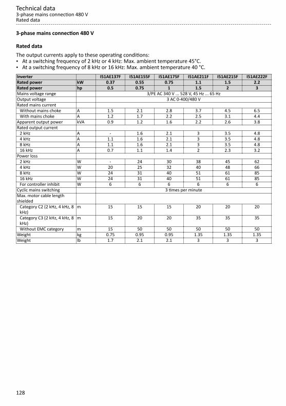
3-phase mains connection 480 V
Rated dataThe output currents apply to these operating conditions:• At a switching frequency of 2 kHz or 4 kHz: Max. ambient temperature 45°C.• At a switching frequency of 8 kHz or 16 kHz: Max. ambient temperature 40 °C.Inverter I51AE137F I51AE155F I51AE175F I51AE211F I51AE215F I51AE222FRated power kW 0.37 0.55 0.75 1.1 1.5 2.2Rated power hp 0.5 0.75 1 1.5 2 3Mains voltage range 3/PE AC 340 V ... 528 V, 45 Hz ... 65 HzOutput voltage 3 AC 0-400/480 VRated mains current Without mains choke A 1.5 2.1 2.8 3.7 4.5 6.5 With mains choke A 1.2 1.7 2.2 2.5 3.1 4.4Apparent output power kVA 0.9 1.2 1.6 2.2 2.6 3.8Rated output current 2 kHz A - 1.6 2.1 3 3.5 4.8 4 kHz A 1.1 1.6 2.1 3 3.5 4.8 8 kHz A 1.1 1.6 2.1 3 3.5 4.8 16 kHz A 0.7 1.1 1.4 2 2.3 3.2Power loss 2 kHz W - 24 30 38 45 62 4 kHz W 20 25 32 40 48 66 8 kHz W 24 31 40 51 61 85 16 kHz W 24 31 40 51 61 85 For controller inhibit W 6 6 6 6 6 6Cyclic mains switching 3 times per minuteMax. motor cable lengthshielded
Category C2 (2 kHz, 4 kHz, 8kHz)
m 15 15 15 20 20 20
Category C3 (2 kHz, 4 kHz, 8kHz)
m 15 20 20 35 35 35
Without EMC category m 15 50 50 50 50 50Weight kg 0.75 0.95 0.95 1.35 1.35 1.35Weight lb 1.7 2.1 2.1 3 3 3
Technical data3-phase mains connection 480 VRated data
128

Inverter I51AE230F I51BE230F I51AE240F I51BE240F I51AE255F I51AE275F I51AE311FRated power kW 3 3 4 4 5.5 7.5 11Rated power hp 4 4 5 5 7.5 10 15Mains voltage range 3/PE AC 340 V ... 528 V, 45 Hz ... 65 HzOutput voltage 3 AC 0-400/480 VRated mains current Without mains choke A 8 8 10.5 10.5 14.3 16.6 23.7 With mains choke A 5.8 5.8 7.5 7.5 10.3 13.1 18.6Apparent output power kVA 4.9 4.9 6.4 6.4 8.7 11 16Rated output current 2 kHz A 6.3 6.3 8.2 8.2 11 14 21 4 kHz A 6.3 6.3 8.2 8.2 11 14 21 8 kHz A 6.3 6.3 8.2 8.2 11 14 21 16 kHz A 4.2 4.2 5.5 5.5 7.3 9.3 14Power loss 2 kHz W 79 79 102 102 137 172 242 4 kHz W 85 85 110 110 145 185 260 8 kHz W 110 110 140 140 190 240 340 16 kHz W 109 109 140 140 189 238 337 For controller inhibit W 6 6 6 6 6 6 6Cyclic mains switching 3 times per minuteMax. motor cable lengthshielded
Category C2 (2 kHz, 4 kHz, 8kHz)
m 20 20 20 20 20 20 20
Category C3 (2 kHz, 4 kHz, 8kHz)
m 35 35 35 35 35 50 50
Without EMC category m 100 50 100 50 100 100 100Weight kg 2.3 1.35 2.3 1.35 2.3 3.7 3.7Weight lb 5 3 5 3 5 8 8
Technical data3-phase mains connection 480 V
Rated data
129

3-phase mains connection 480 V "Light Duty"
Rated dataThe output currents apply to these operating conditions:• At a switching frequency of 2 kHz or 4 kHz: Ambient temperature above 40 °C with a rated output current
reduced by 2.5 %/°C.• If the load characteristic "Light Duty" and the switching frequencies 8 kHz or 16 kHz are selected, only the
values of the load characteristic "Heavy Duty" are reached.Inverter I51AE230F I51BE230F I51AE240F I51BE240F I51AE255F I51AE275F I51AE311FRated power kW 4 4 5.5 5.5 7.5 11 15Rated power hp 5 5 7.5 7.5 10 15 20Mains voltage range 3/PE AC 340 V ... 528 V, 45 Hz ... 65 HzOutput voltage 3 AC 0-400/480 VRated mains current Without mains choke A 8.6 8.6 11.2 11.2 15.3 22 - With mains choke A 6.8 6.8 8.8 8.8 12.1 17.2 22.6Apparent output power kVA 5.9 5.9 8 8 10.5 15 19Rated output current 2 kHz A 7.6 7.6 9.8 9.8 13.2 18.3 25.2 4 kHz A 7.6 7.6 9.8 9.8 13.2 18.3 25.2 8 kHz A - - - - - - - 16 kHz A - - - - - - -Power loss 2 kHz W 94 94 125 125 163 238 290 4 kHz W 100 100 133 133 173 253 309 8 kHz W - - - - - - - 16 kHz W - - - - - - - For controller inhibit W 6 6 6 6 6 6 6Cyclic mains switching 3 times per minuteMax. motor cable lengthshielded
Category C2 (2 kHz, 4 kHz, 8kHz)
m 20 20 20 20 20 20 20
Category C3 (2 kHz, 4 kHz, 8kHz)
m 35 35 35 35 35 50 50
Without EMC category m 100 50 100 50 100 100 100Weight kg 2.3 1.35 2.3 1.35 2.3 3.7 3.7Weight lb 5 3 5 3 5 8 8
Technical data3-phase mains connection 480 V "Light Duty"Rated data
130


Ö Lenze Drives GmbH Postfach 10 13 52, D-31763 Hameln Breslauer Straße 3, D-32699 Extertal Germany HR Lemgo B 6478Ü +49 5154 82-0Ø +49 5154 82-2800Ù [email protected]Ú www.lenze.com
Û Lenze Service GmbH Breslauer Straße 3, D-32699 Extertal GermanyÜ 0080002446877 (24 h Helpline)Ø +49 5154 82-1112Ù [email protected]
© 06/2019 | | 5.0