Embed Size (px)
Citation preview
May 19, 2020 | Revision 0
Submitted to the City of Fernie Prepared by McElhanney Ltd.
Contact Ryan Gibbard, P.Eng. Geotechnical Engineer 778-550-2002 [email protected]
Our file: 2441-01010-00
Address 1800 Willowbrook Drive Cranbrook, BC, V1C 7H9
Mountview Proposed Dike
Development
Geotechnical Assessment
Report

Page | iii
Contents 1. Introduction .......................................................................................................................................... 1
2. Project and Geological Description ................................................................................................... 2
3. Reviewed Information and Documents ............................................................................................. 2
4. Field Assessment ................................................................................................................................ 3
5. Soil and Groundwater Conditions ...................................................................................................... 3
6. Evaluation and Analysis...................................................................................................................... 5
Soil Strength Parameters: ............................................................................................................................. 5
Soil Settlement Beneath Dike: ...................................................................................................................... 6
Permeability and seepage: ............................................................................................................................ 6
Surface erosion of dike slopes: ..................................................................................................................... 7
Surface erosion due to riverside stream action:............................................................................................ 7
Structures in and through the dike: ............................................................................................................... 7
Slope stability of dike: ................................................................................................................................... 8
Seismic Stability and Liquefaction: ............................................................................................................... 8
7. Recommendations ............................................................................................................................... 8
7.1. Site Preparation ................................................................................................................................ 9
7.2. Engineered Fill ................................................................................................................................ 10
7.3. Site Drainage................................................................................................................................... 11
7.4. Groundwater .................................................................................................................................... 11
7.5. Temporary Excavations .................................................................................................................. 11
7.6. Geosynthetics for Subgrade Improvements .................................................................................... 12
8. Design and Construction Review ..................................................................................................... 12
9. Closure ................................................................................................................................................ 13
Page | 1
1. Introduction On behalf of the City of Fernie (the Client), McElhanney Ltd. (McElhanney) has prepared this technical
memo to provide a summary of the subsurface investigation and recommendations for the preliminary
geotechnical assessment completed for the proposed Mountview Dike Improvements Project (the
Project). The proposed project is located adjacent and just south of Mt McLean Drive, and east of Mt
Trinity Avenue at the south end of the Mountview residential area in Fernie, BC.
A test pit programme with field subgrade strength and permeameter testing was undertaken to provide
more qualitative shallow results than a borehole programme, and the Groundtech report (Ref. #4 below)
was relied upon in this study with nearby deep borehole data and testing for the existing Mountview dike.
The results of the geotechnical assessment, analysis, as well as preliminary recommendations on
geotechnical aspects of site development and dike design and construction, are provided in this technical
memo.
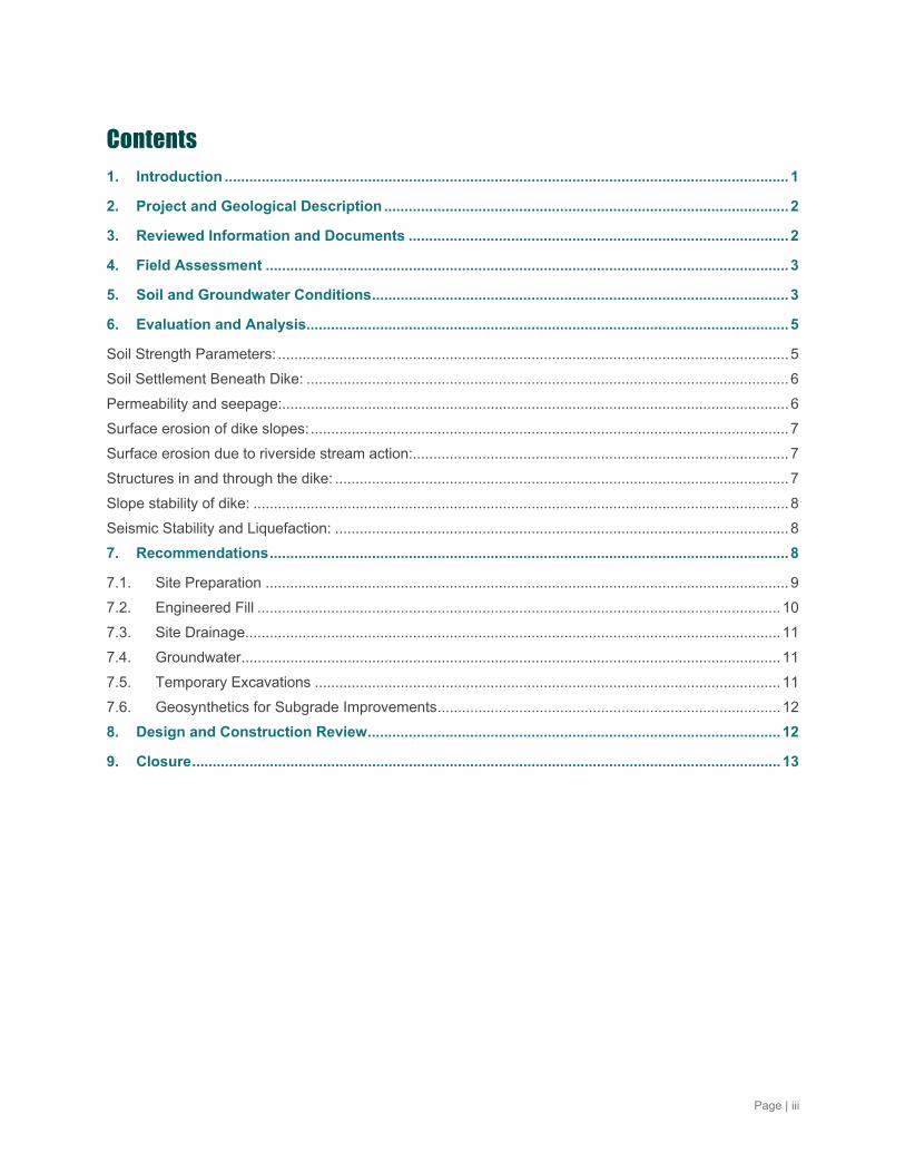
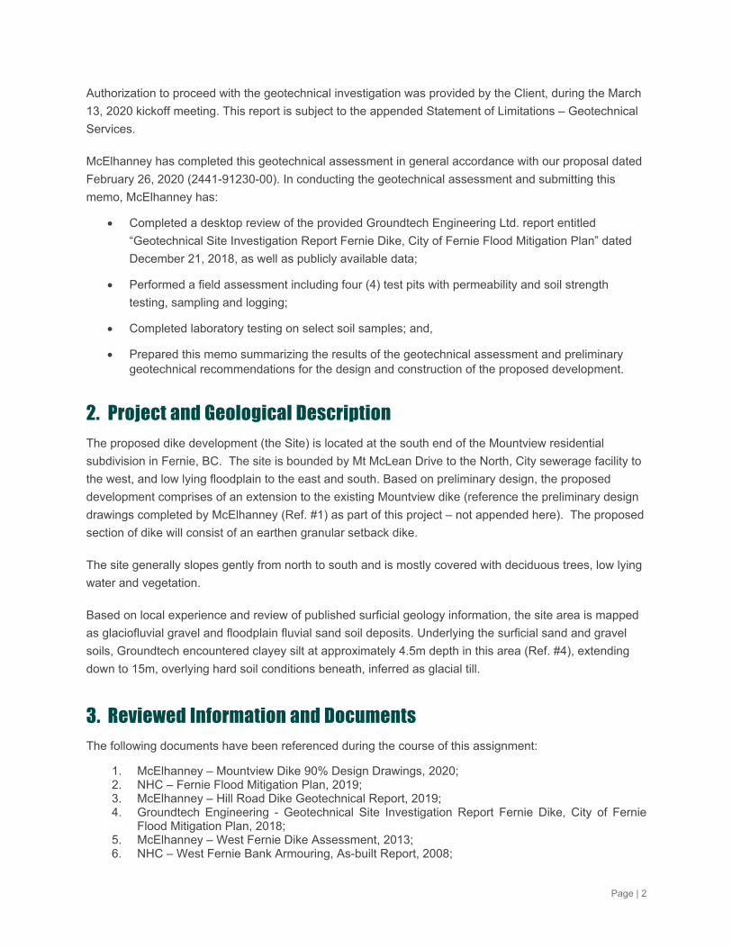
The study location is shown in Figure 1. Exact test pit locations are identified on the logs.
Figure 1 Project Site Location (with Test Pit locations)
Page | 2
Authorization to proceed with the geotechnical investigation was provided by the Client, during the March
13, 2020 kickoff meeting. This report is subject to the appended Statement of Limitations – Geotechnical
Services.
McElhanney has completed this geotechnical assessment in general accordance with our proposal dated
February 26, 2020 (2441-91230-00). In conducting the geotechnical assessment and submitting this
memo, McElhanney has:
Completed a desktop review of the provided Groundtech Engineering Ltd. report entitled
“Geotechnical Site Investigation Report Fernie Dike, City of Fernie Flood Mitigation Plan” dated
December 21, 2018, as well as publicly available data;
Performed a field assessment including four (4) test pits with permeability and soil strength
testing, sampling and logging;
Completed laboratory testing on select soil samples; and,
Prepared this memo summarizing the results of the geotechnical assessment and preliminary geotechnical recommendations for the design and construction of the proposed development.
2. Project and Geological Description The proposed dike development (the Site) is located at the south end of the Mountview residential
subdivision in Fernie, BC. The site is bounded by Mt McLean Drive to the North, City sewerage facility to
the west, and low lying floodplain to the east and south. Based on preliminary design, the proposed
development comprises of an extension to the existing Mountview dike (reference the preliminary design
drawings completed by McElhanney (Ref. #1) as part of this project – not appended here). The proposed
section of dike will consist of an earthen granular setback dike.
The site generally slopes gently from north to south and is mostly covered with deciduous trees, low lying
water and vegetation.
Based on local experience and review of published surficial geology information, the site area is mapped
as glaciofluvial gravel and floodplain fluvial sand soil deposits. Underlying the surficial sand and gravel
soils, Groundtech encountered clayey silt at approximately 4.5m depth in this area (Ref. #4), extending
down to 15m, overlying hard soil conditions beneath, inferred as glacial till.
3. Reviewed Information and Documents The following documents have been referenced during the course of this assignment:
1. McElhanney – Mountview Dike 90% Design Drawings, 2020; 2. NHC – Fernie Flood Mitigation Plan, 2019; 3. McElhanney – Hill Road Dike Geotechnical Report, 2019; 4. Groundtech Engineering - Geotechnical Site Investigation Report Fernie Dike, City of Fernie
Flood Mitigation Plan, 2018; 5. McElhanney – West Fernie Dike Assessment, 2013; 6. NHC – West Fernie Bank Armouring, As-built Report, 2008;
Page | 3
7. NHC – West Fernie Dike Improvements, Preliminary Design Final Report, 2010; 8. Kerr Wood Leidal – West Fernie Dike Improvement Project Phase 2, As-built Report, 2013; 9. Groundtech Engineering – Geotechnical Site Investigation Report, West Fernie Dike
Improvement Project Phase 2, 2012; 10. NHC – West Fernie Dike Improvement Project Phase 3-4, Tender Documents and Proposal,
2013; 11. Golder Associates – Seismic Design Guidelines for Dikes, Prepared for MFLNRO Safety Section,
2014; 12. BC Ministry of Forests, Lands and Natural Resource Operations – General Guidelines for Dike
Maintenance Act Approval for Pipe Crossings of Dikes, 2014 13. BC Ministry of Environment – General Guidelines, Comprehensive Geotechnical Investigation
and Design Report submitted in support of Dike Maintenance Act approval applications, 2011; 14. Province of BC – Dike Design and Construction Guide, 2003; 15. Province of British Columbia, L. Lacelle – BC Soil Survey Report No. 20, Map: Elko 82G/SW and
Cranbrook 82G/NW, 1990; 16. Google – Orthophoto and Aerial Mapping.
4. Field Assessment The geotechnical field assessment was carried out on April 23, 2020, which comprised of four (4) test
pits, with locations depicted on the Figure 1 above. The test pits were dug by Down to Earth Construction
of Sparwood, BC with an excavator to depths ranging from 1.2 to 2.6 mbgs (meters below ground
surface). Following completion of the test pits, they were backfilled with the excavated soil and nominally
compacted with the excavator bucket.
The subsurface conditions encountered at each test pit were observed and recorded by a McElhanney
representative. Detailed soil logs are attached. The soils observed in the field were classified in
accordance with the Modified Unified Classification System for Soils (MUSCS). DCPT and permeameter
field tests were conducted in the test pits where possible, and reports are provided in Attachment C. The
test pit locations were surveyed after completion.
Upon completion of the field program, select soil samples were submitted to Artech Consulting Ltd. for
index testing including moisture content and sieve analysis. The laboratory testing results are
summarized on the soil logs and the laboratory test reports are provided in Attachment C.
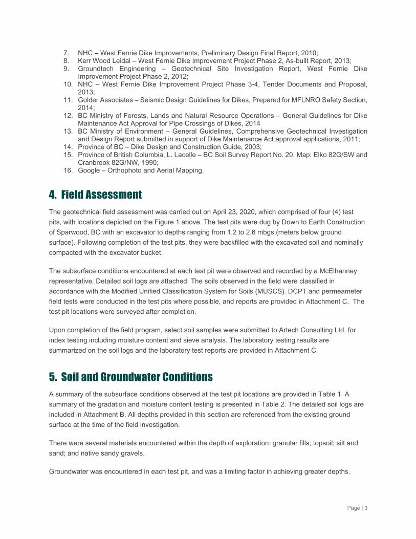
5. Soil and Groundwater Conditions A summary of the subsurface conditions observed at the test pit locations are provided in Table 1. A
summary of the gradation and moisture content testing is presented in Table 2. The detailed soil logs are
included in Attachment B. All depths provided in this section are referenced from the existing ground
surface at the time of the field investigation.
There were several materials encountered within the depth of exploration: granular fills; topsoil; silt and
sand; and native sandy gravels.
Groundwater was encountered in each test pit, and was a limiting factor in achieving greater depths.
Page | 4
Table 1 Summary of Test Pits
Test Location
End of Hole
(mbgs)
Soil Unit (mbgs) Groundwater/Seepage Depth (mbgs) Granular
Fills Topsoil Silt and
Sand Native Sandy Gravel
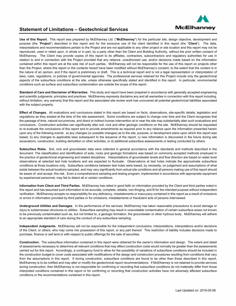
TP20-01 2.6 0-2.45+ N/E N/E N/E 0.9
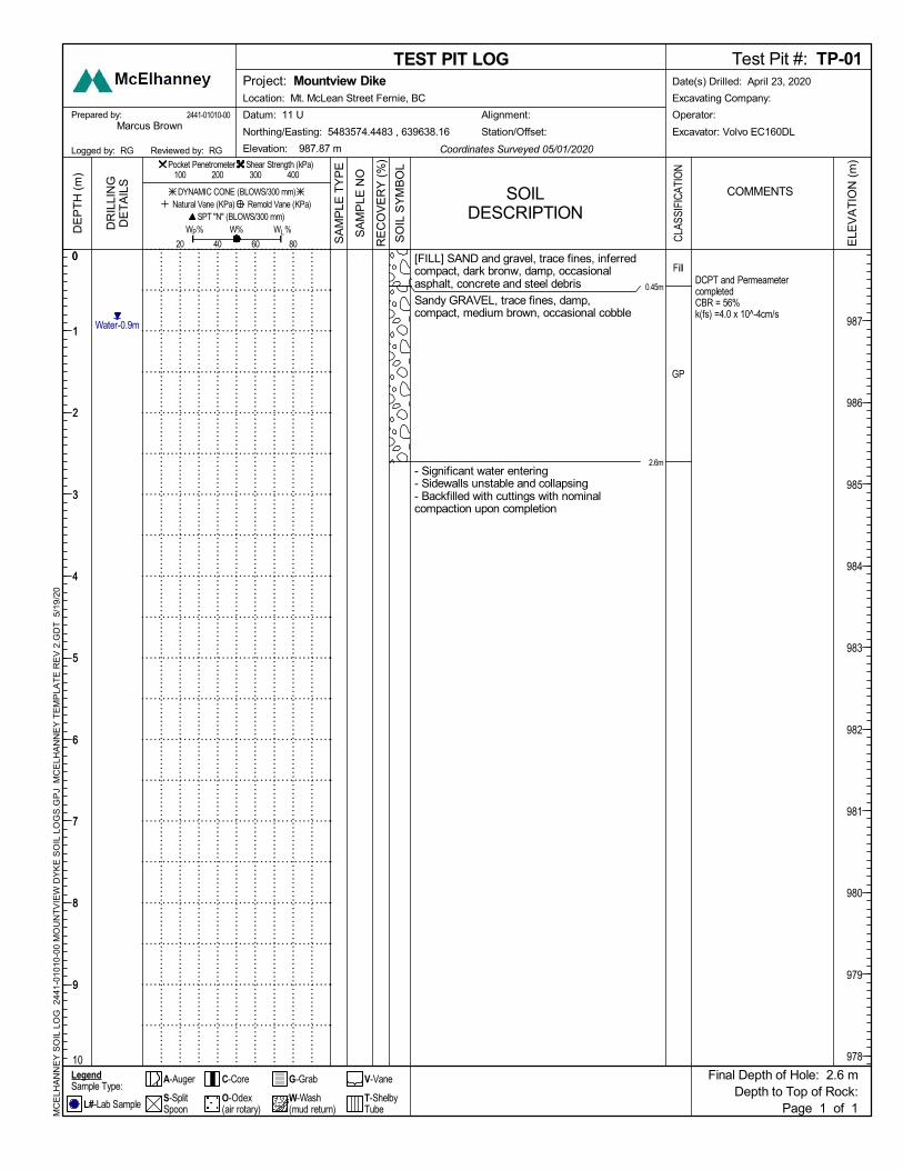
TP20-02 1.2 0.1-1.2+ 0-0.1 N/E N/E 0.8
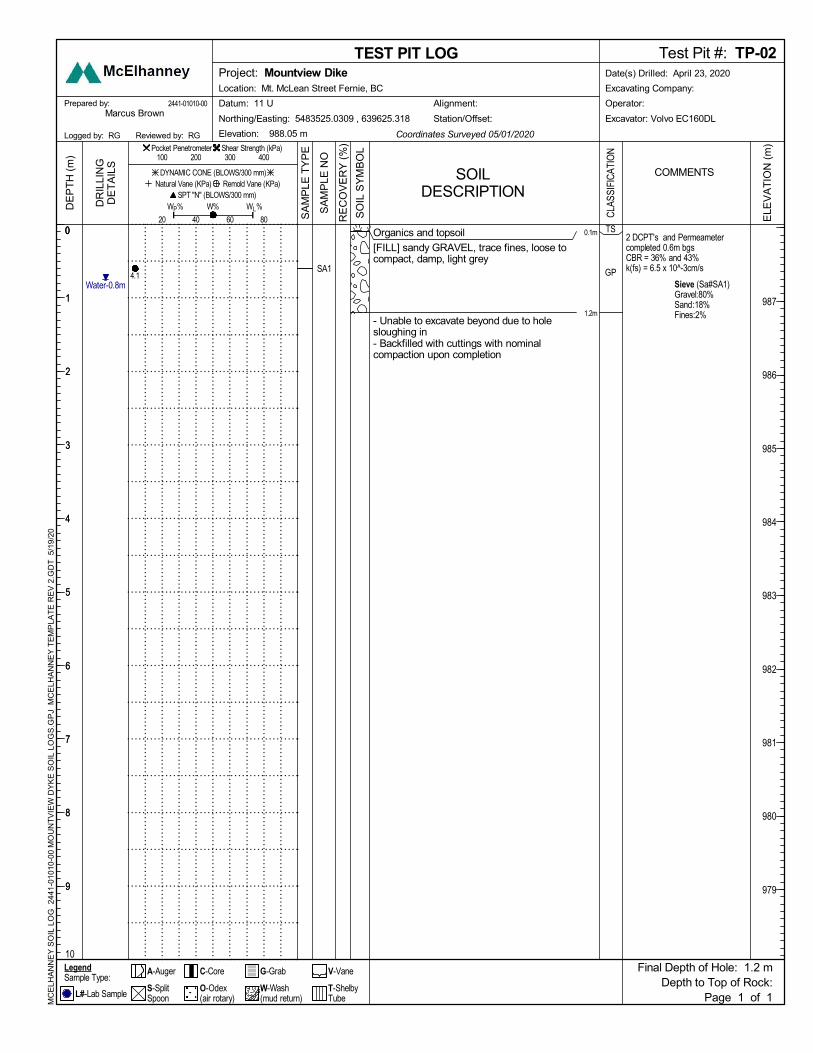
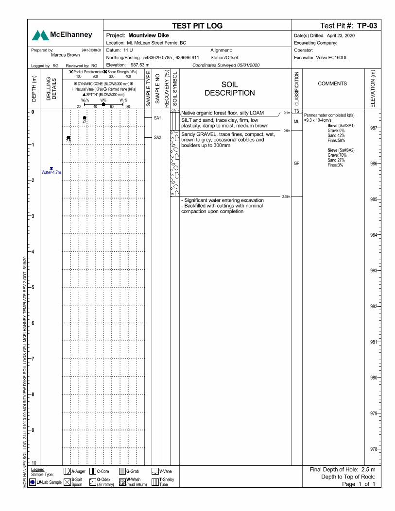
TP20-03 2.45 N/E 0-0.1 0.1-0.6 0.6-2.45+ 1.7
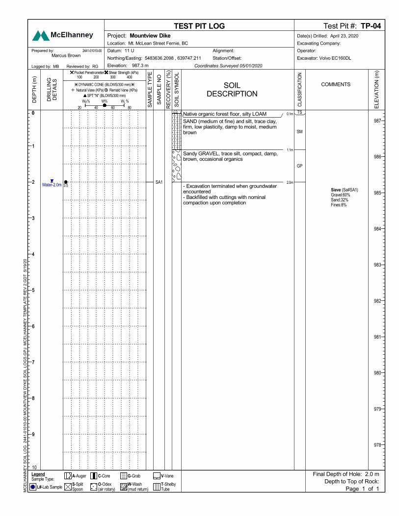
TP20-04 2.0 N/E 0-0.1 0.1-1.1 1.1-2.0+ 2.0
Notes: N/E not encountered
Granular Fills: TP20-01 and TP20-02 were excavated in areas of fill:
HORIZON #1A: YARD FILL ZONE: TP20-01 is located in a built up area of previously placed
yard fills consisting of silty gravels, debris (concrete, steel, wood and asphalt), and clean gravel
fills.
HORIZON #1B: DIKE FILL ZONE: TP20-02 is located on clean granular fill that was previously
placed for the construction of the adjacent sewerage facility, and the Mountview Dike feature (as
investigated by Groundtech – Ref. #4).
HORIZON #2: Topsoil: The entirety of the natural site is overlain by a thin topsoil layer that was 0.1m
thick.
HORIZON #3: Silt and Sand: a fluvial deposit of low plastic silt and medium to fine sand exist over the
site beneath the topsoil. These soils exist in depths ranging from 0.5 to 1.0mbgs. The silt was firm where
it was encountered at or below groundwater, and DCP testing indicated a stiff consistency in the soil
above groundwater.
HORIZON #4: Sandy Gravel: compact glaciofluvial sandy gravel with trace to some fines was
encountered underlying the Silt and Sand layer. These soils begin at depths ranging from 0.6 to 1.1
mbgs, and extend down beyond the test pit limits to an approximate depth of 4.5 mbgs (Ref. #4).
Table 2 Summary of Gradation Results
Test Location Sample Depth (mbgs)
Moisture Content (%)
Gradation
Soil Classification
(MUSCS) Gravel Sand Fines (Silt and
Clay)
TP20-02 S1 (0.6) 4.1 80 18 2 GP
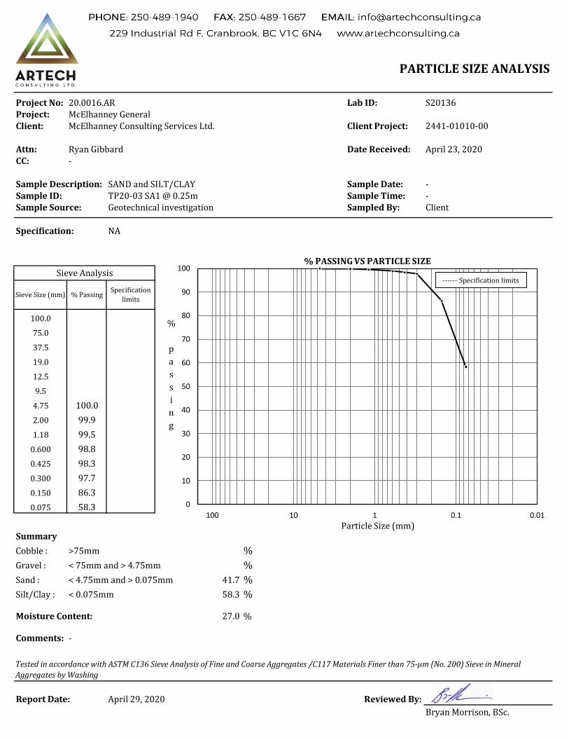
TP20-03 S1 (0.3) 27 0 42 58 ML/SM
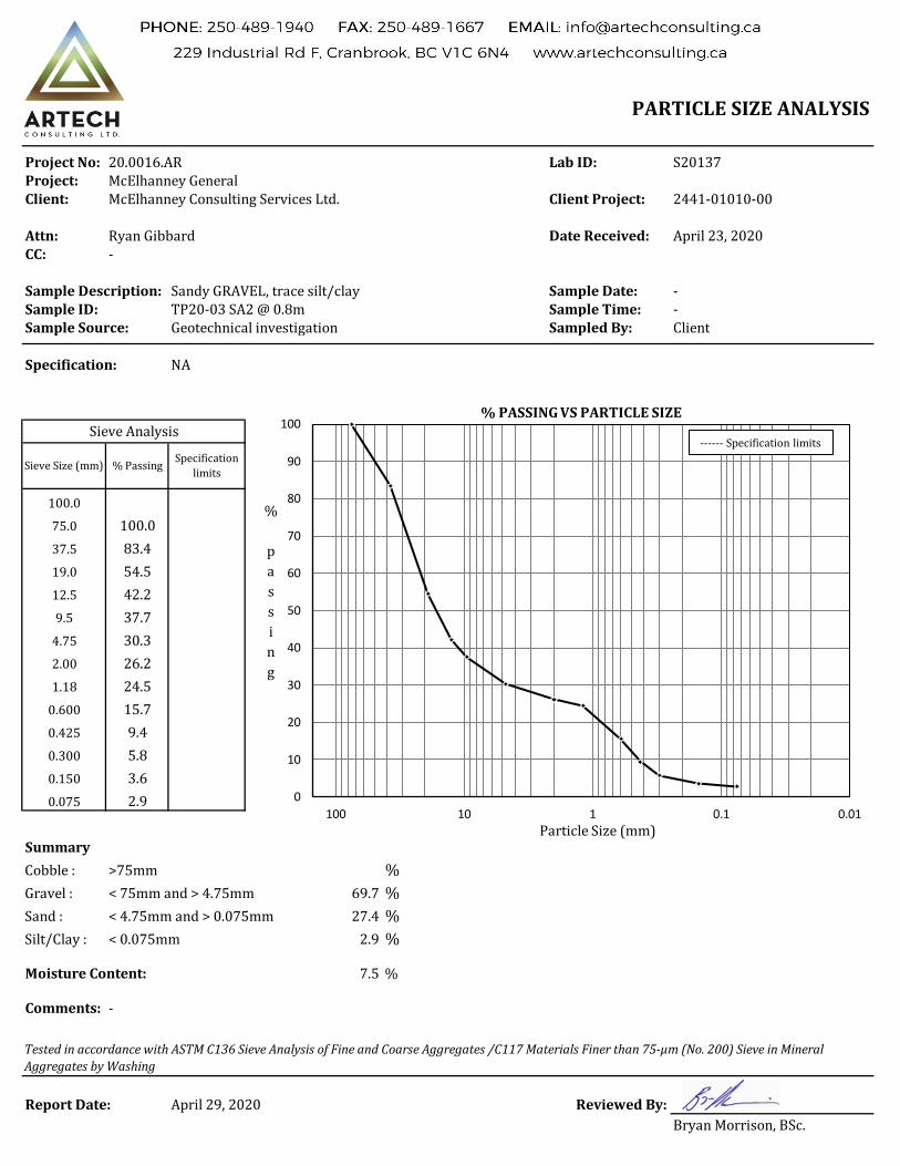
TP20-03 S2 (0.8) 7.5 70 27 3 GP
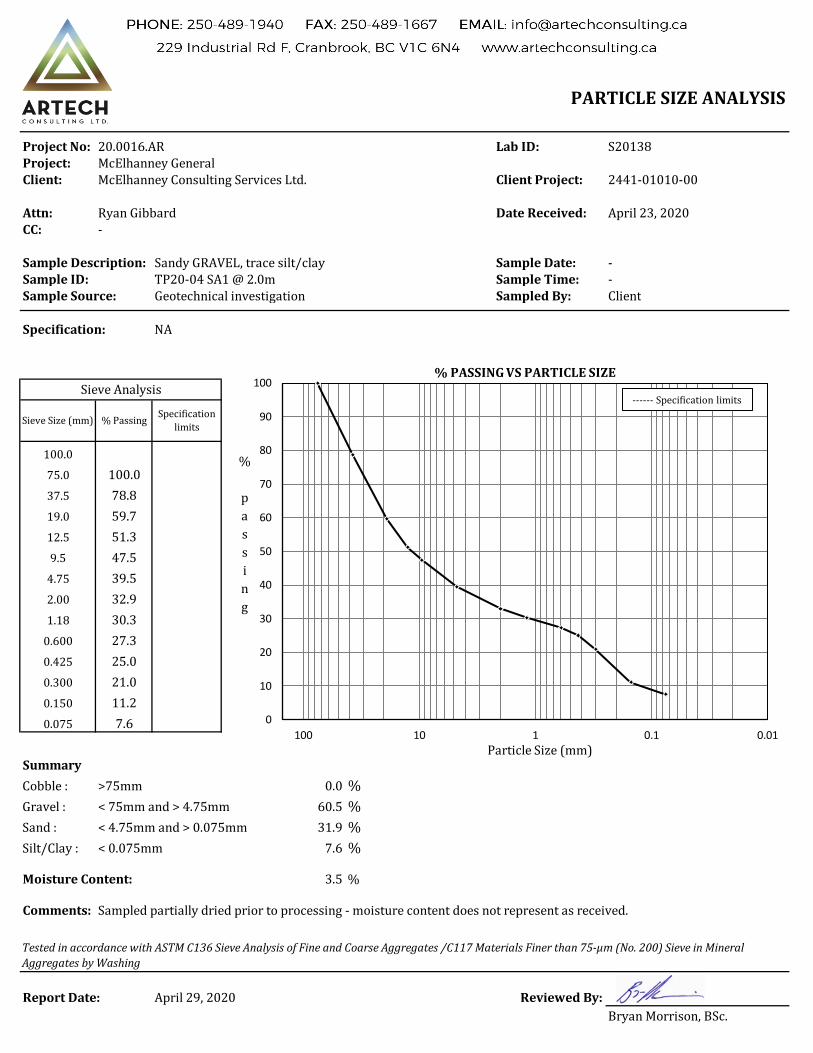
TP20-04 S1 (2.0) N/A 60 32 8 GP
Page | 5
Groundwater: Groundwater was observed in all test pits at the time of excavation as shown in
Table 1. Note that groundwater monitoring instrumentation was not installed as part of the current scope
of work. Standing water was observed nearby and adjacent around the site.
6. Evaluation and Analysis For the purposes of the below evaluation and analysis of the existing site conditions and soils for
placement of the proposed dike, there are a few considerations and design parameters:
1. The gravel yard fill of Horizon #1A in the location of TP20-01 contains significant construction
debris, such as concrete, asphalt, steel and wood. As such, this layer is considered unsuitable
for dike material or subgrade, and must be stripped from within the dike construction footprint
down through any organic layer(s) and topsoil to the suitable native Horizon #3 or #4 soils. Clean
pockets of suitable granular material were observed, and could partially be recovered, stockpiled
and re-used within the project.
2. The clean granular fill of Horizon #1B in the location of TP20-02 is consistent with the nearby
granular Mountview dike fills observed by Groundtech in 2018 (Ref. #4). These previously placed
and compacted gravels are suitable subgrade for dike placement, provided that the top 0.3m is
stripped and the surface compacted in accordance with this report.
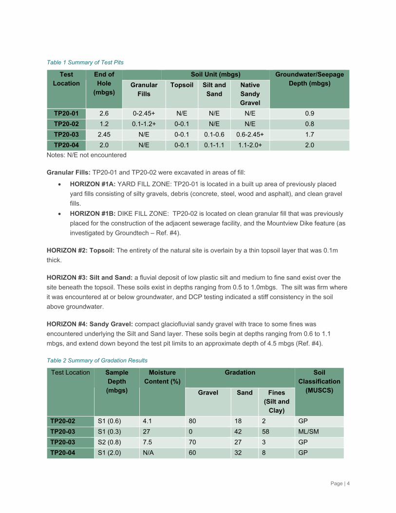
SOIL STRENGTH PARAMETERS:
Soil strength parameters for the near-surface soils were approximated based on field testing at the time of
our investigation. A summary of this analysis is presented in Table 3:
Table 3 Summary of Field Strength Testing and Approximation of Ultimate Soil Bearing values for the Dike
Test Location
Depth (mbgs)
Soil Horizon CBR (%)
Shear Strength (Torvane)
(kPa)
Estimated Internal Soil
Angle of Friction (°)
Estimated Ultimate Soil Bearing (kPa)
TP20-01 0.5 #1A – Yard Fill 56 n/a 42 580
TP20-02 0.6 #1B – Clean Gravel Fill 26 n/a 36 280
TP20-03 0.5 #3 – Sand/Silt 8 50 29 100
TP20-03 0.8 #4 – Sandy Gravel 42 n/a 40 450
Notes: n/a = not applicable
Significantly, the site soils identified all exhibit moderate to strong bearing strength characteristics. Based
on a pseudo footing width typical with the proposed dike, and allowing for some variation of widths, the
Factor of Safety (FoS) for the bearing pressures is conservatively estimated at least 2.5 on the weakest
soil layer observed (sand/silt). Based on this analysis, we confirm that the observed native or clean
granular fill subgrade soils should adequately support the loading of the proposed raised dike feature.
Given the known subsurface and underlying conditions, we confirm that there are no known soil strength
conditions that would impact the dike design.
Page | 6
SOIL SETTLEMENT BENEATH DIKE:
Settlement, based on the assumed loading, is approximated to be less than 20mm post construction,
provided the dike is constructed appropriately and in accordance with the recommendations below.
Consolidation settlement of the deeper clayey silt soils was considered utilizing the consolidation testing
undertaken by Golder for the Groundtech report (Ref. #4), and based on the known depth was
conservatively calculated to be a maximum of 10mm.
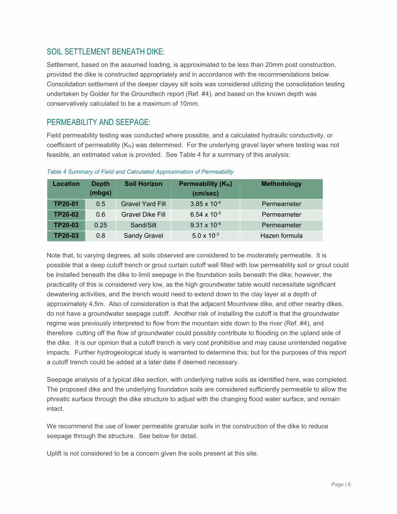
PERMEABILITY AND SEEPAGE:
Field permeability testing was conducted where possible, and a calculated hydraulic conductivity, or
coefficient of permeability (Kfs) was determined. For the underlying gravel layer where testing was not
feasible, an estimated value is provided. See Table 4 for a summary of this analysis:
Table 4 Summary of Field and Calculated Approximation of Permeability
Location Depth (mbgs)
Soil Horizon Permeability (Kfs)
(cm/sec)
Methodology
TP20-01 0.5 Gravel Yard Fill 3.85 x 10⁻⁴ Permeameter
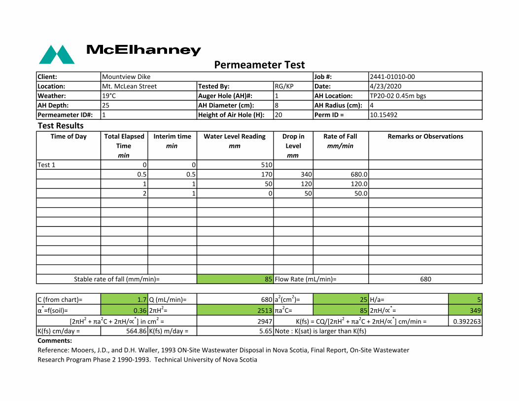
TP20-02 0.6 Gravel Dike Fill 6.54 x 10⁻³ Permeameter
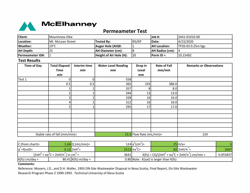
TP20-03 0.25 Sand/Silt 9.31 x 10⁻⁴ Permeameter
TP20-03 0.8 Sandy Gravel 5.0 x 10⁻³ Hazen formula
Note that, to varying degrees, all soils observed are considered to be moderately permeable. It is
possible that a deep cutoff trench or grout curtain cutoff wall filled with low permeability soil or grout could
be installed beneath the dike to limit seepage in the foundation soils beneath the dike; however, the
practicality of this is considered very low, as the high groundwater table would necessitate significant
dewatering activities, and the trench would need to extend down to the clay layer at a depth of
approximately 4.5m. Also of consideration is that the adjacent Mountview dike, and other nearby dikes,
do not have a groundwater seepage cutoff. Another risk of installing the cutoff is that the groundwater
regime was previously interpreted to flow from the mountain side down to the river (Ref. #4), and
therefore cutting off the flow of groundwater could possibly contribute to flooding on the upland side of
the dike. It is our opinion that a cutoff trench is very cost prohibitive and may cause unintended negative
impacts. Further hydrogeological study is warranted to determine this; but for the purposes of this report
a cutoff trench could be added at a later date if deemed necessary.
Seepage analysis of a typical dike section, with underlying native soils as identified here, was completed.
The proposed dike and the underlying foundation soils are considered sufficiently permeable to allow the
phreatic surface through the dike structure to adjust with the changing flood water surface, and remain
intact.
We recommend the use of lower permeable granular soils in the construction of the dike to reduce
seepage through the structure. See below for detail.
Uplift is not considered to be a concern given the soils present at this site.
Page | 7
Since there is no dam core, there are no soil gradation compatibility concerns. Piping failures through
preferential paths can be mitigated by preventing the growth of trees on and near the dam, as well as
monitoring and removing animal burrows and dens on and around the dike to prevent preferential flow
paths from developing on the dike. If paths are observed during routine inspections over the service life of
the dam, a geotechnical engineer should be contacted for input.
SURFACE EROSION OF DIKE SLOPES:
The proposed section of dike will be constructed out of a sand and gravel product with 15-30% silt and
clay to reduce the permeability of the dike. In order to minimize surficial erosion of the dike surface, it is
recommended that the maximum slope angle is to be 2.5:1, and that the dike be compacted to a
minimum of 98% Standard Proctor Maximum Dry Density (SPMDD) in maximum 250mm lifts, and within
3% of the optimum moisture content as derived from the ASTM D-698 Moisture-Density relationship
(Proctor test). The dike slopes will be topsoiled and seeded with a hardy, dense grass seed mixture,
suitable for mitigating any erosion due to rainfall runoff on the dike slopes.
SURFACE EROSION DUE TO RIVERSIDE STREAM ACTION:
The dike is setback from the Elk River by 50-250 m, and a densely treed area runs between the river and
the proposed dike. Based on modelling data from the NHC report (Ref. #2) and our understanding of the
local river hydraulics, this vegetation and setback distance will significantly reduce flood velocities at the
dike. The NHC report (Ref. #2) does not recommend riprap erosion protection for the riverside dike slope,
and no riprap erosion protection is proposed in McElhanney’s design. The grassed riverside slope is
expected to be sufficient to resist the low flood velocities expected against the dike.
STRUCTURES IN AND THROUGH THE DIKE:
It is understood that the design may include a culvert feature through the dike structure. For this
situation, in order to prevent the migration of soils along the path of the pipe surface in accordance with
the Ministry Pipe Crossings of Dikes guidelines (Ref. #11), the following is recommended:
Landside Drainage Fills be installed around the culvert for the first 1/3 of the length of the culvert
length through the dike;
The Drainage Fills shall consist of fine Drain rock backfill (see specified gradation in Table 5
below);
The dike fill shall be placed to 200mm in elevation above the top of the culvert elevation. The
culvert shall be cut down to a depth 200mm below the bottom of the pipe;
A medium strength nonwoven geotextile fabric (see specification in Table 6 below) shall be
placed in one piece longitudinally along the section of drainage fill, covering the bottom and sides,
with sufficient material to cover over top and overlap at least 0.5m;
A 200mm lift of the drainrock material be placed and compacted along the base as bedding;
The culvert pipe be installed, and backfilled and compacted along the sides in 200mm lifts;
A 200mm lift of the drainrock material cap over the pipe and be compacted. The geotextile shall
fold over this material with 0.5m overlap;
At the end of the Drainage Fill within the dike, the geotextile fabric must fold back and be tightly
sealed/taped to the sides of the culvert pipe so as to prevent migration of fines. If this seal cannot
Page | 8
be achieved, then a bedding sand filter (meeting MMCD bedding sand specifications) at least
0.5m wide must be included at the transition between the common dike fill and the Drainage Fill.
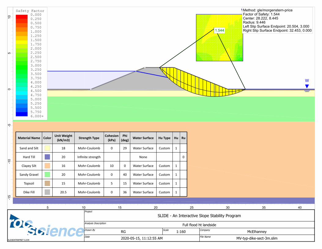
SLOPE STABILITY OF DIKE:
Rocscience Slide (V6.0) was used to evaluate stability of a typical cross section of the dike given the
native foundation soils observed.
Landside stability due to seepage was analyzed. This is considered a steady state seepage condition,
with full saturation of the dike soils. Analysis shows that a dike side slope of 2.5:1 or less is stable with a
Factor of Safety (FOS) greater than 1.5. with the condition that the water level height is less than the top
of the 3m or less height dike structure.
Riverside stability due to draw down was also considered. Given the anticipated moderately well draining
permeabilities of the dike and foundation soils, the materials will provide sufficient drainage given the
anticipated slower drawdown of the river such that elevated pore pressures will not develop and cause
instability (Ref. #4).
Given the anticipated depth to weaker soils of 4.5m (Ref. #4), the limiting stability factor in the dike design
is in fact the quality and slope angle of the dike fill itself. Given such, the stability of the dike in the above
scenarios is considered sufficient provided that the recommendations in this report are followed.
SEISMIC STABILITY AND LIQUEFACTION:
Following the analysis completed by Groundtech for the same soils in 2018 (Ref. #4) it is agreed and
corroborated that, given:
the very low likelihood of seismic activity at this location,
the low probability of liquefaction of the soils of the Fernie floodplain, and
the quality of near surface and surface materials at this site,
that no additional mitigation works are required for this section of dike.
7. Recommendations The geotechnical recommendations provided in this report are based on the understanding of the
proposed dike design and site location as described above. It is recommended that if any changes to the
proposed works or site location are made to what is designed and reviewed for this report that the
undersigned be given the opportunity to assess the applicability of the recommendations provided herein
and/or recommendations for further geotechnical study be provided if required. A geotechnical engineer
should provide additional recommendations if conditions during construction are different than reported
herein.
Based on our project understanding and the findings of this geotechnical assessment, the site appears to
be suitable for dike development from a geotechnical perspective with consideration of the
recommendations and discussion provided in this report. The following sections provide preliminary
Page | 9
discussion and recommendations as input for planning and preliminary design based on the current
understanding of the proposed dike improvement project.
7.1. SITE PREPARATION
Based on the test pit observations, the depth to suitable subgrade soils was 0.1m in native soil and dike
fill locations (Test Pits 20-02, 20-03 and 20-04). In the yard fill area, it is estimated that up to 3.0m of
variable granular fill containing debris will need to be removed down to inorganic, strong suitable native
subgrade similar to the native soil locations. Any soft/loose and/or otherwise unsuitable subgrade areas
otherwise identified at the time of construction should be sub-excavated and replaced with material
meeting the specifications for compacted Engineered Fill (Section 5.2) to design sub-grade elevation for
dike base and other grade-supported portions of the development.
The following general recommendations are provided for subgrade preparation of grade-supported, load-
bearing structures (such as the dike):
Remove any existing vegetation, organic soil, deleterious fill soils/materials, soft/wet soils, and
debris materials underlying load-bearing structures to expose the underlying compact to dense
and/or firm to stiff native inorganic soil subgrade. Note that the subsurface conditions may vary
across the site given the unknown development history and removal of unsuitable soils may be
required to depths beyond design subgrade depths in some areas not specifically tested.
All prepared subgrades should be inspected in the field by a Geotechnical Engineer or their
representative to confirm that the subgrade conditions are consistent with the design conditions
assumed in this report. Soil subgrade should be proof-rolled using either a fully loaded tandem
truck or a single-drum compaction roller under the direction of the Geotechnical Engineer or their
representative to identify any loose/soft areas before placement of any Engineered Fill.
Soft, loose, wet, and/or otherwise unsuitable subgrade surfaces can be repaired by sub-
excavation and replacement with Engineered Fill compacted to 98% Standard Proctor Maximum
Dry Density (SPMDD) unless otherwise specified in this report (see Section 7.2).
Subject to field review at the time of construction, approved subgrade of any sub-excavations
within the proposed development limits should be backfilled to design subgrade elevation with
approved fill material in accordance with the material selection, placement and compaction
specifications for Engineered Fill, as defined in Section 7.2.
General site grading fills, if required to raise local site grades, should consist of approved common fill
comprising clean inorganic granular materials or an approve alternative from approved local or imported
sources. Subject to surface grading, drainage and settlement tolerances required for site grading design,
common fill materials may be placed in uniform layers not exceeding 300 mm thickness and compacted
to a minimum of 95% Standard Proctor Maximum Dry Density (SPMDD) unless otherwise specified in this
report.
Page | 10
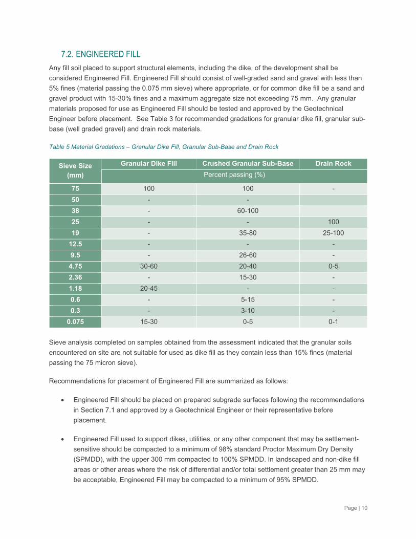
7.2. ENGINEERED FILL
Any fill soil placed to support structural elements, including the dike, of the development shall be
considered Engineered Fill. Engineered Fill should consist of well-graded sand and gravel with less than
5% fines (material passing the 0.075 mm sieve) where appropriate, or for common dike fill be a sand and
gravel product with 15-30% fines and a maximum aggregate size not exceeding 75 mm. Any granular
materials proposed for use as Engineered Fill should be tested and approved by the Geotechnical
Engineer before placement. See Table 3 for recommended gradations for granular dike fill, granular sub-
base (well graded gravel) and drain rock materials.
Table 5 Material Gradations – Granular Dike Fill, Granular Sub-Base and Drain Rock
Sieve Size (mm)
Granular Dike Fill Crushed Granular Sub-Base Drain Rock
Percent passing (%)
75 100 100 -
50 - -
38 - 60-100
25 - - 100
19 - 35-80 25-100
12.5 - - -
9.5 - 26-60 -
4.75 30-60 20-40 0-5
2.36 - 15-30 -
1.18 20-45 - -
0.6 - 5-15 -
0.3 - 3-10 -
0.075 15-30 0-5 0-1
Sieve analysis completed on samples obtained from the assessment indicated that the granular soils
encountered on site are not suitable for used as dike fill as they contain less than 15% fines (material
passing the 75 micron sieve).
Recommendations for placement of Engineered Fill are summarized as follows:
Engineered Fill should be placed on prepared subgrade surfaces following the recommendations
in Section 7.1 and approved by a Geotechnical Engineer or their representative before
placement.
Engineered Fill used to support dikes, utilities, or any other component that may be settlement-
sensitive should be compacted to a minimum of 98% standard Proctor Maximum Dry Density
(SPMDD), with the upper 300 mm compacted to 100% SPMDD. In landscaped and non-dike fill
areas or other areas where the risk of differential and/or total settlement greater than 25 mm may
be acceptable, Engineered Fill may be compacted to a minimum of 95% SPMDD.
Page | 11
Engineered Fill should be placed in horizontal lifts not exceeding 250mm vertical loose thickness,
dependant on the type of compaction equipment used. Engineered Fill should be placed at
moisture conditions conducive to achieving compaction specifications (typically within 3% of the
optimum moisture content) as determined by a Standard Proctor Moisture-Density Test (ASTM
D698).
Any permanent dike slopes should have a maximum slope angle of 2.5H:1V for Engineered Fill
and should be adequately protected from erosion.
Continuous Quality Control (QC) compaction testing and construction reviews should be
performed by the Geotechnical Engineer’s representative or a qualified testing agency during
placement of all Engineered Fill to verify compliance with the above recommendations.
7.3. SITE DRAINAGE
Positive surface drainage should be maintained away from the development areas in all directions,
considering existing infrastructure adjacent to the proposed development. Surface drainage of all
developed areas should be maintained with minimum 2% cross-slope recommended, particularly away
from structures and dikes.
7.4. GROUNDWATER
Groundwater was encountered at depths of 0.8 to 2.0m at all test pits at time of excavation. It is likely
that groundwater seepage will be encountered during construction. The groundwater should not be
permitted to collect in the bottom of the excavations during construction and a contingency plan should be
made to pump out or drain excavations with sump pumps and to divert water away from the excavation. If
significant groundwater seepage or softening subgrade soils are encountered the geotechnical engineer
should be contacted to review.
7.5. TEMPORARY EXCAVATIONS
To protect existing utilities and adjacent infrastructure during construction, and to allow for safe worker
access, temporary excavation slopes shall be constructed as per most current applicable Worksafe BC
regulations.
For planning purposes, it is recommended that temporary excavation slopes be sloped no steeper than
1.5 Horizontal to 1 Vertical (1.5H:1V) within areas of fined grained soils or fine-grained sands. Flatter
slopes or other temporary support measures may be required if significant seepage or groundwater inflow
conditions are encountered. Steeper temporary slopes of up to 1.0H:1.0V may be considered in shallow
excavations based on conditions encountered during construction. If steeper slopes or slopes greater
than 6 m in height are to be considered, or poor/saturated soil conditions or significant seepage is
encountered, a Geotechnical Engineer should be consulted to review.
Page | 12
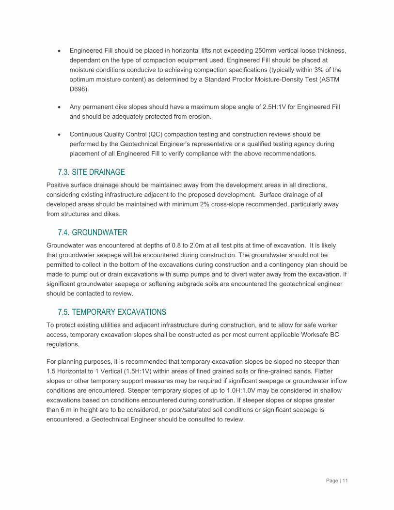
7.6. GEOSYNTHETICS FOR SUBGRADE IMPROVEMENTS
A geotextile (or possibly geogrid) may be required to improve compaction over soft/wet subgrade
locations as determined by the geotechnical engineer or their representative during subgrade
assessment. It is also recommended as a filter between culvert bedding backfill and dike fill (see above).
A medium weight non-woven geotextile is specified with the properties indicated in Table 6 below.
Table 6 Specifications for Non-woven Geotextile – Moderate Survivability (1)
Property (2) ASTM
Test Unit Value
Grab Tensile Strength D4632 N 700(3)
Trapezoid Tear Strength D4533 N 250
CBR Puncture Strength D6241 N 1,400
Permittivity D4491 sec-1 0.02
Apparent Opening Size D4751 mm 0.60
Ultraviolet Stability (4) D 7238 % strength retained at
500 hours
70
Notes: 1. GRI GT13(a) – ASTM Version, Revision 4, June 20, 2017. Geosynthetic Institute2. All values are minimum average roll values (MARV) except AOS which is a maximum average roll value and
UV stability which is a minimum average value.3. Elongation >50%.4. ‘Evaluation to be on 50 mm strip tensile specimens after 500 hours exposure.
The non-woven geotextile should be placed above the prepared subgrade as per the manufacturers’
specifications.
8. Design and Construction ReviewThe recommendations provided coincide with the 90% design drawings and stated project assumptions
above in mind, and it is recommended that any further alterations to the design be reviewed by a
geotechnical engineer to verify that the geotechnical recommendations and what further geotechnical
assessment may be required for final design and construction.
To issue applicable Dike Maintenance Act letters of assurance and/or construction QA/QC letters, all
backfill and Engineered Fill subgrade shall be reviewed by the geotechnical engineer or their
representative as specified in this report. McElhanney can provide QA material testing services during
construction if requested.
Page | 13
9. Closure We trust that this information is sufficient for your present needs. Should you have any questions or
require additional information, please do not hesitate to contact the author of the document.
Sincerely,
McElhanney Ltd.
Prepared By:
Ryan Gibbard, P.Eng. Senior Geotechnical Engineer [email protected] 778-550-2002
Reviewed By:
Melissa Chappel, P.Eng Karen Prezelj, P.Eng Geotechnical Engineer Project Manager, Civil Engineer [email protected] [email protected]
Attachments:
Statement of Limitations – Geotechnical Services
Attachment A – Test Pit Logs
Attachment B – Field Test Results
Attachment C – Laboratory Test Reports
Attachment D – Slide Analysis Printouts
Page | 14
STATEMENT OF LIMITATIONS –
GEOTECHNICAL SERVICES
Statement of Limitations – Geotechnical Services
Last Updated on: 2019-05-08
Use of this Report. This report was prepared by McElhanney Ltd. ("McElhanney") for the particular site, design objective, development and purpose (the “Project”) described in this report and for the exclusive use of the client identified in this report (the “Client”). The data, interpretations and recommendations pertain to the Project and are not applicable to any other project or site location and this report may not be reproduced, used or relied upon, in whole or in part, by a party other than the Client and Building Authority, without the prior written consent of McElhanney. The Client may provide copies of this report to its affiliates, contractors, subcontractors and regulatory authorities for use in relation to and in connection with the Project provided that any reliance, unauthorized use, and/or decisions made based on the information contained within this report are at the sole risk of such parties. McElhanney will not be responsible for the use of this report on projects other than the Project, where this report or the contents hereof have been modified without McElhanney’s consent, to the extent that the content is in the nature of an opinion, and if the report is preliminary or draft. This is a technical report and is not a legal representation or interpretation of laws, rules, regulations, or policies of governmental agencies. The professional services retained for this Project include only the geotechnical aspects of the subsurface conditions at the site, unless otherwise specifically stated and identified in this report. In particular, environmental conditions such as surface and subsurface contamination are outside the scope of this report.
Standard of Care and Disclaimer of Warranties. This study and report have been prepared in accordance with generally accepted engineering and scientific judgments, principles and practices. McElhanney expressly disclaims any and all warranties in connection with this report including, without limitation, any warranty that this report and the associated site review work has uncovered all potential geotechnical liabilities associated with the subject property.
Effect of Changes. All evaluations and conclusions stated in this report are based on facts, observations, site-specific details, legislation and regulations as they existed at the time of the site assessment. Some conditions are subject to change over time and the Client recognizes that the passage of time, natural occurrences, and direct or indirect human intervention at or near the site may substantially alter such evaluations and conclusions. Construction activities can significantly alter soil, rock and other geologic conditions on the site. McElhanney should be requested to re-evaluate the conclusions of this report and to provide amendments as required prior to any reliance upon the information presented herein upon any of the following events: a) any changes (or possible changes) as to the site, purpose, or development plans upon which this report was based, b) any changes to applicable laws subsequent to the issuance of the report, c) new information is discovered in the future during site excavations, construction, building demolition or other activities, or d) additional subsurface assessments or testing conducted by others.
Subsurface Risks. Soil, rock and groundwater data were collected in general accordance with the standards and methods described in the document. The classification and identification of soils, rocks and geologic formations was based on commonly accepted methods employed in the practice of geotechnical engineering and related disciplines. Interpretations of groundwater levels and flow direction are based on water level observations at selected test hole locations and are expected to fluctuate. Observations at test holes indicate the approximate subsurface conditions at those locations only. Subsurface conditions between test holes were based, by necessity, on judgement and assumptions of what exists between the actual locations sampled, and may vary significantly from actual site conditions and all persons making use of this report should be aware of, and accept, this risk. Even a comprehensive sampling and testing program, implemented in accordance with appropriate equipment by experienced personnel, may fail to detect all or certain conditions.
Information from Client and Third Parties. McElhanney has relied in good faith on information provided by the Client and third parties noted in this report and has assumed such information to be accurate, complete, reliable, non-fringing, and fit for the intended purpose without independent verification. McElhanney accepts no responsibility for any deficiency, misstatements or inaccuracy contained in this report as a result of omissions or errors in information provided by third parties or for omissions, misstatements or fraudulent acts of persons interviewed.
Underground Utilities and Damages. In the performance of the services, McElhanney has taken reasonable precautions to avoid damage or injury to subterranean structures or utilities. Subsurface sampling may result in unavoidable contamination of certain subsurface areas not known to be previously contaminated such as, but not limited to, a geologic formation, the groundwater or other hydrous body. McElhanney will adhere to an appropriate standard of care during the conduct of any subsurface sampling.
Independent Judgments. McElhanney will not be responsible for the independent conclusions, interpretations, interpolations and/or decisions of the Client, or others, who may come into possession of this report, or any part thereof. This restriction of liability includes decisions made to purchase, finance or sell land or with respect to public offerings for the sale of securities.
Construction. The subsurface information contained in this report were obtained for the owner’s information and design. The extent and detail of assessments necessary to determine all relevant conditions that may affect construction costs would normally be greater than the assessments carried out for this report. Accordingly, a contingency fund to allow for the possibility of variations of subsurface conditions should be included in the construction budget to cover costs associated with modifications of the design and construction procedures resulting from conditions that vary from the assumptions in this report. If during construction, subsurface conditions are found to be other than those described in this report, McElhanney is to be notified and may alter or modify the geotechnical report recommendations. If McElhanney is not retained to provide services during construction, then McElhanney is not responsible for confirming or recording that subsurface conditions do not materially differ from those interpreted conditions contained in this report or for confirming or recording that construction activities have not adversely affected subsurface conditions or the recommendations contained in this report.

Page | 15
APPENDIX A – TEST PIT LOGS
0.45m
2.6m
DCPT and PermeametercompletedCBR = 56%k(fs) =4.0 x 10^-4cm/s
[FILL] SAND and gravel, trace fines, inferredcompact, dark bronw, damp, occasionalasphalt, concrete and steel debris
Sandy GRAVEL, trace fines, damp,compact, medium brown, occasional cobble
- Significant water entering- Sidewalls unstable and collapsing- Backfilled with cuttings with nominalcompaction upon completion
Fill
GP
L#-Lab SampleW-Wash(mud return)
Elevation: 987.87 m
987
986
985
984
983
982
981
980
979
978
Marcus BrownPrepared by:
Logged by: RG Reviewed by: RG
SO
IL S
YM
BO
L
RE
CO
VE
RY
(%
)
SA
MP
LE N
O
SA
MP
LE T
YP
E1
2
3
4
5
6
7
8
9
Operator:
CLA
SSIF
ICAT
ION
Location: Mt. McLean Street Fernie, BC
Date(s) Drilled: April 23, 2020
Coordinates Surveyed 05/01/2020
Project: Mountview Dike
ELE
VA
TIO
N (
m)
1
2
3
4
5
6
7
8
9
LegendSample Type:
S-SplitSpoon
O-Odex(air rotary)
T-ShelbyTube
C-CoreA-Auger G-Grab V-Vane
SOILDESCRIPTION
00
Page 1 of 1
DE
PT
H (
m)
DR
ILLI
NG
DE
TA
ILS
Alignment:
10
0
Northing/Easting: 5483574.4483 , 639638.16
Final Depth of Hole: 2.6 mDepth to Top of Rock:
Station/Offset:
Excavating Company:
2441-01010-00
TEST PIT LOG
Datum: 11 U
COMMENTS
Excavator: Volvo EC160DL
Test Pit #: TP-01M
CE
LHA
NN
EY
SO
IL L
OG
244
1-01
010-
00 M
OU
NT
VIE
W D
YK
E S
OIL
LO
GS
.GP
J M
CE
LHA
NN
EY
TE
MP
LAT
E R
EV
2.G
DT
5/1
9/2
0
DYNAMIC CONE (BLOWS/300 mm)
W % W %L
20 40 60 80P W%
SPT "N" (BLOWS/300 mm) Natural Vane (KPa) Remold Vane (KPa)
100 200 300 400 Pocket Penetrometer Shear Strength (kPa)
Water-0.9m
0.1m
1.2m
SA1
2 DCPT's and Permeametercompleted 0.6m bgsCBR = 36% and 43%k(fs) = 6.5 x 10^-3cm/s
Organics and topsoil
[FILL] sandy GRAVEL, trace fines, loose tocompact, damp, light grey
- Unable to excavate beyond due to holesloughing in- Backfilled with cuttings with nominalcompaction upon completion
TS
GPSieve (Sa#SA1)Gravel:80%Sand:18%Fines:2%
L#-Lab SampleW-Wash(mud return)
Elevation: 988.05 m
987
986
985
984
983
982
981
980
979
Marcus BrownPrepared by:
Logged by: RG Reviewed by: RG
SO
IL S
YM
BO
L
RE
CO
VE
RY
(%
)
SA
MP
LE N
O
SA
MP
LE T
YP
E1
2
3
4
5
6
7
8
9
Operator:
CLA
SSIF
ICAT
ION
Location: Mt. McLean Street Fernie, BC
Date(s) Drilled: April 23, 2020
Coordinates Surveyed 05/01/2020
Project: Mountview Dike
ELE
VA
TIO
N (
m)
1
2
3
4
5
6
7
8
9
LegendSample Type:
S-SplitSpoon
O-Odex(air rotary)
T-ShelbyTube
C-CoreA-Auger G-Grab V-Vane
SOILDESCRIPTION
00
Page 1 of 1
DE
PT
H (
m)
DR
ILLI
NG
DE
TA
ILS
Alignment:
10
0
Northing/Easting: 5483525.0309 , 639625.318
Final Depth of Hole: 1.2 mDepth to Top of Rock:
Station/Offset:
Excavating Company:
2441-01010-00
TEST PIT LOG
Datum: 11 U
COMMENTS
Excavator: Volvo EC160DL
Test Pit #: TP-02M
CE
LHA
NN
EY
SO
IL L
OG
244
1-01
010-
00 M
OU
NT
VIE
W D
YK
E S
OIL
LO
GS
.GP
J M
CE
LHA
NN
EY
TE
MP
LAT
E R
EV
2.G
DT
5/1
9/2
0
DYNAMIC CONE (BLOWS/300 mm)
W % W %L
20 40 60 80P W%
SPT "N" (BLOWS/300 mm) Natural Vane (KPa) Remold Vane (KPa)
100 200 300 400 Pocket Penetrometer Shear Strength (kPa)
Water-0.8m4.1
0.1m
0.6m
2.45m
SA1
SA2
Permeameter completed k(fs) =9.3 x 10⁻⁴cm/s
Native organic forest floor, silty LOAM
SILT and sand, trace clay, firm, lowplasticity, damp to moist, medium brown
Sandy GRAVEL, trace fines, compact, wet,brown to grey, occasional cobbles andboulders up to 300mm
- Significant water entering excavation- Backfilled with cuttings with nominalcompaction upon completion
TS
ML
GP
Sieve (Sa#SA1)Gravel:0%Sand:42%Fines:58%
Sieve (Sa#SA2)Gravel:70%Sand:27%Fines:3%
L#-Lab SampleW-Wash(mud return)
Elevation: 987.53 m
987
986
985
984
983
982
981
980
979
978
Marcus BrownPrepared by:
Logged by: RG Reviewed by: RG
SO
IL S
YM
BO
L
RE
CO
VE
RY
(%
)
SA
MP
LE N
O
SA
MP
LE T
YP
E1
2
3
4
5
6
7
8
9
Operator:
CLA
SSIF
ICAT
ION
Location: Mt. McLean Street Fernie, BC
Date(s) Drilled: April 23, 2020
Coordinates Surveyed 05/01/2020
Project: Mountview Dike
ELE
VA
TIO
N (
m)
1
2
3
4
5
6
7
8
9
LegendSample Type:
S-SplitSpoon
O-Odex(air rotary)
T-ShelbyTube
C-CoreA-Auger G-Grab V-Vane
SOILDESCRIPTION
00
Page 1 of 1
DE
PT
H (
m)
DR
ILLI
NG
DE
TA
ILS
Alignment:
10
0
Northing/Easting: 5483629.0785 , 639696.911
Final Depth of Hole: 2.5 mDepth to Top of Rock:
Station/Offset:
Excavating Company:
2441-01010-00
TEST PIT LOG
Datum: 11 U
COMMENTS
Excavator: Volvo EC160DL
Test Pit #: TP-03M
CE
LHA
NN
EY
SO
IL L
OG
244
1-01
010-
00 M
OU
NT
VIE
W D
YK
E S
OIL
LO
GS
.GP
J M
CE
LHA
NN
EY
TE
MP
LAT
E R
EV
2.G
DT
5/1
9/2
0
DYNAMIC CONE (BLOWS/300 mm)
W % W %L
20 40 60 80P W%
SPT "N" (BLOWS/300 mm) Natural Vane (KPa) Remold Vane (KPa)
100 200 300 400 Pocket Penetrometer Shear Strength (kPa)
Water-1.7m
27
7.5
0.1m
1.1m
2.0mSA1
Native organic forest floor, silty LOAM
SAND (medium ot fine) and silt, trace clay,firm, low plasticity, damp to moist, mediumbrown
Sandy GRAVEL, trace silt, compact, damp,brown, occasional organics
- Excavation terminated when groundwaterencountered- Backfilled with cuttings with nominalcompaction upon completion
TS
SM
GP
Sieve (Sa#SA1)Gravel:60%Sand:32%Fines:8%
L#-Lab SampleW-Wash(mud return)
Elevation: 987.3 m
987
986
985
984
983
982
981
980
979
978
Marcus BrownPrepared by:
Logged by: MB Reviewed by: RG
SO
IL S
YM
BO
L
RE
CO
VE
RY
(%
)
SA
MP
LE N
O
SA
MP
LE T
YP
E1
2
3
4
5
6
7
8
9
Operator:
CLA
SSIF
ICAT
ION
Location: Mt. McLean Street Fernie, BC
Date(s) Drilled: April 23, 2020
Coordinates Surveyed 05/01/2020
Project: Mountview Dike
ELE
VA
TIO
N (
m)
1
2
3
4
5
6
7
8
9
LegendSample Type:
S-SplitSpoon
O-Odex(air rotary)
T-ShelbyTube
C-CoreA-Auger G-Grab V-Vane
SOILDESCRIPTION
00
Page 1 of 1
DE
PT
H (
m)
DR
ILLI
NG
DE
TA
ILS
Alignment:
10
0
Northing/Easting: 5483636.2098 , 639747.211
Final Depth of Hole: 2.0 mDepth to Top of Rock:
Station/Offset:
Excavating Company:
2441-01010-00
TEST PIT LOG
Datum: 11 U
COMMENTS
Excavator: Volvo EC160DL
Test Pit #: TP-04M
CE
LHA
NN
EY
SO
IL L
OG
244
1-01
010-
00 M
OU
NT
VIE
W D
YK
E S
OIL
LO
GS
.GP
J M
CE
LHA
NN
EY
TE
MP
LAT
E R
EV
2.G
DT
5/1
9/2
0
DYNAMIC CONE (BLOWS/300 mm)
W % W %L
20 40 60 80P W%
SPT "N" (BLOWS/300 mm) Natural Vane (KPa) Remold Vane (KPa)
100 200 300 400 Pocket Penetrometer Shear Strength (kPa)
Water-2.0m 3.5

Page | 16
APPENDIX B – FIELD TEST RESULTS

Client: Job #:
Location: Tested By: RG/KP Date:
Weather: Auger Hole (AH)#: 1 AH Location:
AH Depth: AH Diameter (cm): 8 AH Radius (cm):
Permeameter ID#: Height of Air Hole (H): 20 Perm ID =
Time of Day Total Elapsed
Time
min
Interim time
min
Water Level Reading
mm
Drop in
Level
mm
Rate of Fall
mm/min
Test 1 0 0 640
0.5 0.5 375 265 530.0
1 1 320 55 55.0
2 1 313 7 7.0
3 1 308 5 5.0
4 1 303 5 5.0
5 1 298 5 5.0
10 5 275 23 4.6
5 Flow Rate (mL/min)=
C (from chart)= 1.7 Q (mL/min)= 40 a2(cm2)= 25 H/a= 5
α*=f(soil)= 0.36 2πH
2= 2513 πa
2C= 85 2πH/∝
*= 349
2947 0.023074
K(fs) cm/day = 33.23 K(fs) m/day = 0.33
Permeameter Test
Test Results
Mountview Dike
Remarks or Observations
1
2441-01010-00
4/23/2020
TP20-01 0.5m bgs
4
10.15492
40
[2πH2 + πa
2C + 2πH/∝
*] in cm
2 = K(fs) = CQ/[2πH
2 + πa
2C + 2πH/∝
*] cm/min =
Reference: Mooers, J.D., and D.H. Waller, 1993 ON-Site Wastewater Disposal in Nova Scotia, Final Report, On-Site Wastewater
Research Program Phase 2 1990-1993. Technical University of Nova Scotia
Comments:
Mt. McLean Street
19°C
25
Note : K(sat) is larger than K(fs)
Stable rate of fall (mm/min)=
Client: Job #:
Location: Tested By: RG/KP Date:
Weather: Auger Hole (AH)#: 1 AH Location:
AH Depth: AH Diameter (cm): 8 AH Radius (cm):
Permeameter ID#: Height of Air Hole (H): 20 Perm ID =
Time of Day Total Elapsed
Time
min
Interim time
min
Water Level Reading
mm
Drop in
Level
mm
Rate of Fall
mm/min
Test 1 0 0 510
0.5 0.5 170 340 680.0
1 1 50 120 120.0
2 1 0 50 50.0
85 Flow Rate (mL/min)=
C (from chart)= 1.7 Q (mL/min)= 680 a2(cm2)= 25 H/a= 5
α*=f(soil)= 0.36 2πH
2= 2513 πa
2C= 85 2πH/∝
*= 349
2947 0.392263
K(fs) cm/day = 564.86 K(fs) m/day = 5.65
Permeameter Test
Test Results
Mountview Dike
Remarks or Observations
1
2441-01010-00
4/23/2020
TP20-02 0.45m bgs
4
10.15492
680
[2πH2 + πa
2C + 2πH/∝
*] in cm
2 = K(fs) = CQ/[2πH
2 + πa
2C + 2πH/∝
*] cm/min =
Reference: Mooers, J.D., and D.H. Waller, 1993 ON-Site Wastewater Disposal in Nova Scotia, Final Report, On-Site Wastewater
Research Program Phase 2 1990-1993. Technical University of Nova Scotia
Comments:
Mt. McLean Street
19°C
25
Note : K(sat) is larger than K(fs)
Stable rate of fall (mm/min)=
Client: Job #:
Location: Tested By: RG/KP Date:
Weather: Auger Hole (AH)#: 1 AH Location:
AH Depth: AH Diameter (cm): 8 AH Radius (cm):
Permeameter ID#: Height of Air Hole (H): 20 Perm ID =
Time of Day Total Elapsed
Time
min
Interim time
min
Water Level Reading
mm
Drop in
Level
mm
Rate of Fall
mm/min
Test 1 0 0 558
0.5 0.5 365 193 386.0
1 1 357 8 8.0
2 1 344 13 13.0
3 1 328 16 16.0
4 1 312 16 16.0
5 1 295 17 17.0
15.5 Flow Rate (mL/min)=
C (from chart)= 1.64 Q (mL/min)= 124 a2(cm2)= 25 H/a= 5
α*=f(soil)= 0.12 2πH
2= 2513 πa
2C= 82 2πH/∝
*= 1047
3642 0.055837
K(fs) cm/day = 80.41 K(fs) m/day = 0.80
Permeameter Test
Test Results
Mountview Dike
Remarks or Observations
1
2441-01010-00
4/23/2020
TP20-03 0.25m bgs
4
10.15492
124
[2πH2 + πa
2C + 2πH/∝
*] in cm
2 = K(fs) = CQ/[2πH
2 + πa
2C + 2πH/∝
*] cm/min =
Reference: Mooers, J.D., and D.H. Waller, 1993 ON-Site Wastewater Disposal in Nova Scotia, Final Report, On-Site Wastewater
Research Program Phase 2 1990-1993. Technical University of Nova Scotia
Comments:
Mt. McLean Street
19°C
25
Note : K(sat) is larger than K(fs)
Stable rate of fall (mm/min)=
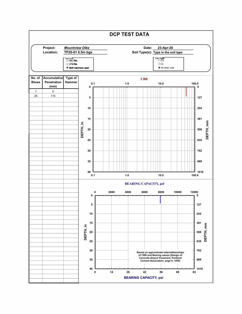
DCP TEST DATA
Project: Mountview Dike Date: 23-Apr-20
Location: TP20-01 0.5m bgs Soil Type(s): Type in the soil type
No. of Accumulative Type of
Blows Penetration Hammer
(mm)
1 0
25 110
0
5
10
15
20
25
30
35
40
0.1 1.0 10.0 100.0
0
127
254
381
508
635
762
889
1016
0.1 1.0 10.0 100.0
DE
PT
H, in
.CBR
DE
PT
H, m
m
10.1 lbs.17.6 lbs.Both hammers used
Soil TypeSoil TypeCHCLAll other soils
10.1 lbs.17.6 lbs.Both hammers used
Hammer
0
127
254
381
508
635
762
889
1016
0 14 28 42 56 69 83
0
5
10
15
20
25
30
35
40
0 2000 4000 6000 8000 10000 12000
DE
PT
H, m
m
BEARING CAPACITY, psi
DE
PT
H, in
BEARING CAPACITY, psf
Based on approximate interrelationshipsof CBR and Bearing values (Design ofConcrete Airport Pavement, Portland Cement Association, page 8, 1955)
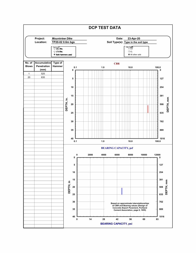
DCP TEST DATA
Project: Mountview Dike Date: 23-Apr-20
Location: TP20-02 0.6m bgs Soil Type(s): Type in the soil type
No. of Accumulative Type of
Blows Penetration Hammer
(mm)
1 525
20 635
0
5
10
15
20
25
30
35
40
0.1 1.0 10.0 100.0
0
127
254
381
508
635
762
889
1016
0.1 1.0 10.0 100.0
DE
PT
H, in
.CBR
DE
PT
H, m
m
10.1 lbs.17.6 lbs.Both hammers used
Soil TypeSoil TypeCHCLAll other soils
10.1 lbs.17.6 lbs.Both hammers used
Hammer
0
127
254
381
508
635
762
889
1016
0 14 28 42 56 69 83
0
5
10
15
20
25
30
35
40
0 2000 4000 6000 8000 10000 12000
DE
PT
H, m
m
BEARING CAPACITY, psi
DE
PT
H, in
BEARING CAPACITY, psf
Based on approximate interrelationshipsof CBR and Bearing values (Design ofConcrete Airport Pavement, Portland Cement Association, page 8, 1955)
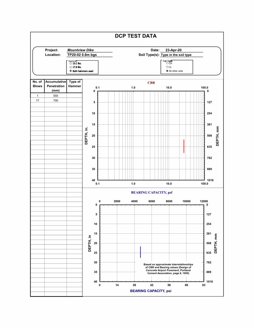
DCP TEST DATA
Project: Mountview Dike Date: 23-Apr-20
Location: TP20-02 0.6m bgs Soil Type(s): Type in the soil type
No. of Accumulative Type of
Blows Penetration Hammer
(mm)
1 555
17 700
0
5
10
15
20
25
30
35
40
0.1 1.0 10.0 100.0
0
127
254
381
508
635
762
889
1016
0.1 1.0 10.0 100.0
DE
PT
H, in
.CBR
DE
PT
H, m
m
10.1 lbs.17.6 lbs.Both hammers used
Soil TypeSoil TypeCHCLAll other soils
10.1 lbs.17.6 lbs.Both hammers used
Hammer
0
127
254
381
508
635
762
889
1016
0 14 28 42 56 69 83
0
5
10
15
20
25
30
35
40
0 2000 4000 6000 8000 10000 12000
DE
PT
H, m
m
BEARING CAPACITY, psi
DE
PT
H, in
BEARING CAPACITY, psf
Based on approximate interrelationshipsof CBR and Bearing values (Design ofConcrete Airport Pavement, Portland Cement Association, page 8, 1955)
Page | 17
APPENDIX C – LABORATORY TEST RESULTS

Project No: 20.0016.AR Lab ID: S20135
Project: McElhanney General
Client: McElhanney Consulting Services Ltd. Client Project: 2441-01010-00
Attn: Ryan Gibbard Date Received:
CC: -
Sample Date:
Sample Time: -
Sample Description: GRAVEL, some sand, trace silt/clay Sample ID: TP20-02 SA1 @ 0.6m
Sample Source: Geotechnical investigation Sampled By: Client
Specification: NA
100.0 #N/A
75.0 100.0
37.5 62.6
19.0 36.9
12.5 28.7
9.5 25.2
4.75 19.7
2.00 16.1
1.18 14.4
0.600 12.0
0.425 9.8
0.300 7.2
0.150 3.2
0.075 2.0
Summary
Cobble : >75mm %
Gravel : < 75mm and > 4.75mm 80.3 %
Sand : < 4.75mm and > 0.075mm 17.7 %
Silt/Clay : < 0.075mm 2.0 %
Moisture Content: 4.1 %
Comments: -
Reviewed By:
Bryan Morrison, BSc.
PARTICLE SIZE ANALYSIS
April 23, 2020
-
Report Date:
Sieve Analysis
Sieve Size (mm) % PassingSpecification
limits
Tested in accordance with ASTM C136 Sieve Analysis of Fine and Coarse Aggregates /C117 Materials Finer than 75-μm (No. 200) Sieve in Mineral
Aggregates by Washing
April 29, 2020
0
10
20
30
40
50
60
70
80
90
100
0.010.1110100
%
p
a
s
s
i
n
g
Particle Size (mm)
% PASSING VS PARTICLE SIZE
------ Specification limits
Project No: 20.0016.AR Lab ID: S20136
Project: McElhanney General
Client: McElhanney Consulting Services Ltd. Client Project: 2441-01010-00
Attn: Ryan Gibbard Date Received:
CC: -
Sample Description: SAND and SILT/CLAY Sample Date:
Sample ID: TP20-03 SA1 @ 0.25m Sample Time: -
Sample Source: Geotechnical investigation Sampled By: Client
Specification: NA
100.0 #N/A
75.0 #N/A
37.5 #N/A
19.0 #N/A
12.5 #N/A
9.5 #N/A
4.75 100.0
2.00 99.9
1.18 99.5
0.600 98.8
0.425 98.3
0.300 97.7
0.150 86.3
0.075 58.3
Summary
Cobble : >75mm %
Gravel : < 75mm and > 4.75mm %
Sand : < 4.75mm and > 0.075mm 41.7 %
Silt/Clay : < 0.075mm 58.3 %
Moisture Content: 27.0 %
Comments: -
Reviewed By:
Bryan Morrison, BSc.
PARTICLE SIZE ANALYSIS
April 23, 2020
-
Report Date:
Sieve Analysis
Sieve Size (mm) % PassingSpecification
limits
Tested in accordance with ASTM C136 Sieve Analysis of Fine and Coarse Aggregates /C117 Materials Finer than 75-μm (No. 200) Sieve in Mineral
Aggregates by Washing
April 29, 2020
0
10
20
30
40
50
60
70
80
90
100
0.010.1110100
%
p
a
s
s
i
n
g
Particle Size (mm)
% PASSING VS PARTICLE SIZE
------ Specification limits
Project No: 20.0016.AR Lab ID: S20137
Project: McElhanney General
Client: McElhanney Consulting Services Ltd. Client Project: 2441-01010-00
Attn: Ryan Gibbard Date Received:
CC: -
Sample Description: Sandy GRAVEL, trace silt/clay Sample Date:
Sample ID: TP20-03 SA2 @ 0.8m Sample Time: -
Sample Source: Geotechnical investigation Sampled By: Client
Specification: NA
100.0 #N/A
75.0 100.0
37.5 83.4
19.0 54.5
12.5 42.2
9.5 37.7
4.75 30.3
2.00 26.2
1.18 24.5
0.600 15.7
0.425 9.4
0.300 5.8
0.150 3.6
0.075 2.9
Summary
Cobble : >75mm %
Gravel : < 75mm and > 4.75mm 69.7 %
Sand : < 4.75mm and > 0.075mm 27.4 %
Silt/Clay : < 0.075mm 2.9 %
Moisture Content: 7.5 %
Comments: -
Reviewed By:
Bryan Morrison, BSc.
PARTICLE SIZE ANALYSIS
April 23, 2020
-
Report Date:
Sieve Analysis
Sieve Size (mm) % PassingSpecification
limits
Tested in accordance with ASTM C136 Sieve Analysis of Fine and Coarse Aggregates /C117 Materials Finer than 75-μm (No. 200) Sieve in Mineral
Aggregates by Washing
April 29, 2020
0
10
20
30
40
50
60
70
80
90
100
0.010.1110100
%
p
a
s
s
i
n
g
Particle Size (mm)
% PASSING VS PARTICLE SIZE
------ Specification limits
Project No: 20.0016.AR Lab ID: S20138
Project: McElhanney General
Client: McElhanney Consulting Services Ltd. Client Project: 2441-01010-00
Attn: Ryan Gibbard Date Received:
CC: -
Sample Description: Sandy GRAVEL, trace silt/clay Sample Date:
Sample ID: TP20-04 SA1 @ 2.0m Sample Time: -
Sample Source: Geotechnical investigation Sampled By: Client
Specification: NA
100.0 #N/A
75.0 100.0
37.5 78.8
19.0 59.7
12.5 51.3
9.5 47.5
4.75 39.5
2.00 32.9
1.18 30.3
0.600 27.3
0.425 25.0
0.300 21.0
0.150 11.2
0.075 7.6
Summary
Cobble : >75mm 0.0 %
Gravel : < 75mm and > 4.75mm 60.5 %
Sand : < 4.75mm and > 0.075mm 31.9 %
Silt/Clay : < 0.075mm 7.6 %
Moisture Content: 3.5 %
Comments: Sampled partially dried prior to processing - moisture content does not represent as received.
Reviewed By:
Bryan Morrison, BSc.
Report Date:
Sieve Analysis
Sieve Size (mm) % PassingSpecification
limits
Tested in accordance with ASTM C136 Sieve Analysis of Fine and Coarse Aggregates /C117 Materials Finer than 75-μm (No. 200) Sieve in Mineral
Aggregates by Washing
April 29, 2020
PARTICLE SIZE ANALYSIS
April 23, 2020
-
0
10
20
30
40
50
60
70
80
90
100
0.010.1110100
%
p
a
s
s
i
n
g
Particle Size (mm)
% PASSING VS PARTICLE SIZE
------ Specification limits
Page | 18
APPENDIX D – SLIDE ANALYSIS PRINTOUTS

1.8941.8941.894
W
1.8941.8941.894
Material Name Color Unit Weight(kN/m3) Strength Type Cohesion
(kPa)Phi(deg) Water Surface Hu Type Hu Ru
Sand and Silt 18 Mohr‐Coulomb 0 29 Water Surface Custom 1
Hard Till 20 Infinite strength None 0
Clayey Silt 16 Mohr‐Coulomb 10 0 Water Surface Custom 1
Sandy Gravel 20 Mohr‐Coulomb 0 40 Water Surface Custom 1
Topsoil 15 Mohr‐Coulomb 5 15 Water Surface Custom 1
Dike Fill 20.5 Mohr‐Coulomb 0 36 Water Surface Custom 1
FS: 1.89401Method: gle/morgenstern-priceFS: 1.894010Center: 11.803, 10.394Radius: 10.092Left Slip Surface Endpoint: 11.754, 0.302Right Slip Surface Endpoint: 18.672, 3.000Left Slope Intercept: 11.754 2.500Right Slope Intercept: 18.672 3.000
Safety Factor0.0000.2500.5000.7501.0001.2501.5001.7502.0002.2502.5002.7503.0003.2503.5003.7504.0004.2504.5004.7505.0005.2505.5005.7506.000+
105
0-5
-10
-15
-5 0 5 10 15 20 25 30
Analysis Description Full flood htCompany McElhanneyScale 1:160Drawn By RGFile Name MV-typ-dike-sect-3m.slimDate 2020-05-15, 11:12:55 AM
Project
SLIDE - An Interactive Slope Stability Program
SLIDEINTERPRET 6.039
1.5441.5441.544
W
1.5441.5441.544
Material Name Color Unit Weight(kN/m3) Strength Type Cohesion
(kPa)Phi(deg) Water Surface Hu Type Hu Ru
Sand and Silt 18 Mohr‐Coulomb 0 29 Water Surface Custom 1
Hard Till 20 Infinite strength None 0
Clayey Silt 16 Mohr‐Coulomb 10 0 Water Surface Custom 1
Sandy Gravel 20 Mohr‐Coulomb 0 40 Water Surface Custom 1
Topsoil 15 Mohr‐Coulomb 5 15 Water Surface Custom 1
Dike Fill 20.5 Mohr‐Coulomb 0 36 Water Surface Custom 1
Method: gle/morgenstern-priceFactor of Safety: 1.544Center: 28.222, 8.445Radius: 9.446Left Slip Surface Endpoint: 20.504, 3.000Right Slip Surface Endpoint: 32.453, 0.000
Safety Factor0.0000.2500.5000.7501.0001.2501.5001.7502.0002.2502.5002.7503.0003.2503.5003.7504.0004.2504.5004.7505.0005.2505.5005.7506.000+
105
0-5
-10
-15
5 10 15 20 25 30 35 40
Analysis Description Full flood ht landsideCompany McElhanneyScale 1:160Drawn By RGFile Name MV-typ-dike-sect-3m.slimDate 2020-05-15, 11:12:55 AM
Project
SLIDE - An Interactive Slope Stability Program
SLIDEINTERPRET 6.039