Embed Size (px)
Citation preview

MouseBot technical manual
3/8/2016 Instructions and technical documentation
This document contains full technical documentation of the IEEE Concordia MouseBot, including instructions, schematics, circuit explanations, and design decisions and considerations.

MouseBot technical manual
MouseBot technical manualU S E A N D A S S E M B L Y I N S T R U C T I O N S , C I R C U I T E X P L A N A T I O N , A N D D E S I G N D E C I S I O N S
USAGE INSTRUCTIONS:To use your MouseBot, you will need a large, smooth surface and a power source. Your power
source can be a bright light (such as a powerful flashlight, but ideally a bright sunny day) and/or batteries.
How to use your MouseBot
Prior to use:Before installing the batteries, remove jumper J2. If you are using rechargeable batteries, install
jumper J1.
Your MouseBot is now powered and ready to use. If you have multiple MouseBots, install jumper J3.
Place the MouseBot on a flat, smooth surface. If battery power is available, it will immediately start driving towards the brightest area it can see; otherwise, it will need to charge up from the solar cell prior to moving.
During use:MouseBot will drive towards the brightest spot it sees. If the surface is homogenously lit, such
as by fluorescent lights or sunlight, MouseBot will appear to drive randomly. More entertainingly, if the room is dimly lit, MouseBot will chase a flashlight beam around the room. If the flashlight beam is held steady and no batteries are installed, MouseBot will park and re-charge in the light.
If multiple MouseBots are in use and jumper J3 is installed, the MouseBots will chase each other; in this case, bright lighting is recommended, as MouseBot will experience difficulty in locating the brightest areas to recharge.
After use:Exercise caution when picking up MouseBot after use; try to grip it only by the edges of the
PCB, not the underside.
Before storing MouseBot, remove the batteries if they are installed. Install jumper J2. MouseBot is now ready for storage.
Page 1

MouseBot technical manual
ASSEMBLY INSTRUCTIONS:Basic soldering skills are required to assemble the MouseBot. If you do not have soldering
experience, IEEE Concordia will be happy to help. Ideally, take our soldering tutorial; we offer it once per semester. If that is not a viable option, come to the IEEE Concordia lab during our open lab hours (http://ieee.concordia.ca/services/hours), and we would be happy to teach you how to solder.
Bill of Materials:Part name (qty) Part Value Schematic Identifier
Battery Holder (1) NA NA
Storage Capacitor (1) 1F @ 6V C1
1n4001 diode (4) NA D1,D2,D4,D5
In5819 diode (1) NA D6
1n4148 diode (1) NA D3
IR LED (1) 100 ma @ 1.4 V. 940 nm D7
Jumper (3) NA NA
Motor (2) 5 volt tolerant M1,M2
Photocell (1) 6V PH1
Photodiode (2) LTR-4206E PH2,PH3
PMOS (1) FQU8P Q1
NMOS (1) MTP3055 Q2
LM358 op-amp (1) NA U2
LM386 op-amp (1) NA U1
100 K resistor (2) ¼ watt R1,R2
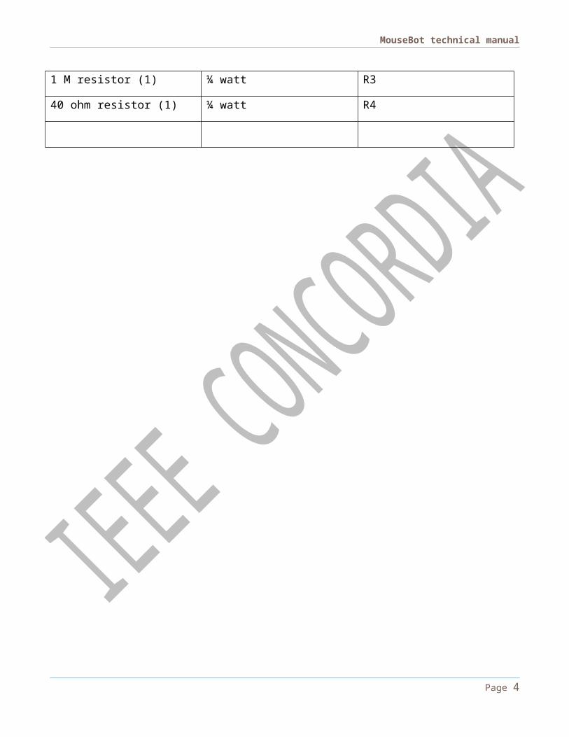
1 M resistor (1) ¼ watt R3
40 ohm resistor (1) ¼ watt R4
Page 2

MouseBot technical manual
Assembly substrate; MouseBot PCB, electronics PCB, perf-board, protoboard…There are several options for the MouseBot chassis. The most convenient is to use the
MouseBot PCB files provided; not only are all the components and traces placed, but the PCB itself serves as a chassis on which the motors and ball caster can be attached. IEEE Concordia may be able to assist you in etching your own circuit board; alternatively, there are many online companies willing to produce a circuit board. While the MouseBot PCB is the fastest and most convenient way to get off the ground, it may prove the most expensive to manufacture; most fabricators charge by the square inch, and MouseBot PCB is 6”x6”. A lower cost alternative is to simply manufacture the electronics PCB, and mount it on a user-supplied chassis. The chassis can be anything, though the MouseBot as designed uses a 6” by 6” equilateral triangle. The same approach can be used with a perf-board or solderless breadboard.
The CapacitorAfter much discussion, it was decided not to include the supercapacitor in the robot kits due to
safety concerns. Among other problems, the manufacturer packages the capacitors in their fully charged state. MouseBot will work with any capacitor rated for 5.5VDC or greater. We recommend a minimum value of 1 Farad. Such capacitors can readily be ordered online via Digikey or Mouser.
Order of assemblyMouseBot has been designed to be easily assembled. There are no critical steps or sequences
that need to be followed, with the one important caveat: do not install C1, the battery holder, the solar panel, or the motors until every other part is soldered. We strongly recommend installing C1 last, and with jumper J2 installed. The motors need to spin in opposite directions; if MouseBot drives only in circles, reverse the connection of the inside motor.
Page 3
MouseBot technical manual
TECHNICAL DOCUMENTATION:Circuit Analysis:
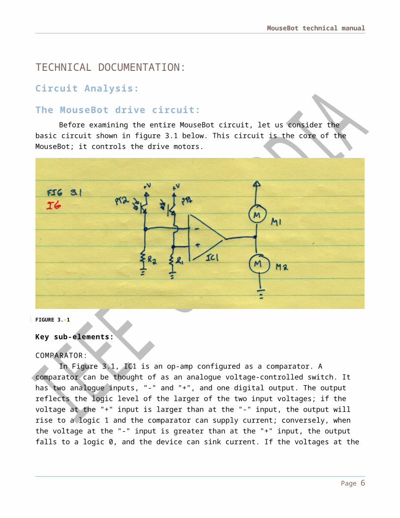
The MouseBot drive circuit:Before examining the entire MouseBot circuit, let us consider the basic circuit shown in figure
3.1 below. This circuit is the core of the MouseBot; it controls the drive motors.
FIGURE 3. 1
Key sub-elements:
COMPARATOR:In Figure 3.1, IC1 is an op-amp configured as a comparator. A comparator can be thought of as
an analogue voltage-controlled switch. It has two analogue inputs, "-" and "+", and one digital output. The output reflects the logic level of the larger of the two input voltages; if the voltage at the "+" input is larger than at the "-" input, the output will rise to a logic 1 and the comparator can supply current; conversely, when the voltage at the "-" input is greater than at the "+" input, the output falls to a logic 0, and the device can sink current. If the voltages at the "-" and "+" terminals are too similar for the device to discriminate, the output becomes indeterminate; this condition should be avoided.
PHOTO-TRANSISTOR:In Figure 3.1, transistors PT1 and PT2 are photo-transistors. In a conventional bipolar transistor,
large current flows can be induced by applying a biasing current to the base of the transistor; most transistors offer amplification factors on the order of a hundred-fold, so a fairly small amount of biasing current can trigger large flows of current through the transistor. In a standard transistor, this biasing current is applied electrically; in the case of a photo-transistor, as the name implies, this activation
Page 4

MouseBot technical manual
energy is supplied by photons of light striking the transistor's base. In this specific application, the transistors can be considered light-sensitive resistors; as the amount of light they "see" increases, their "resistance" decreases and the current through them increases.
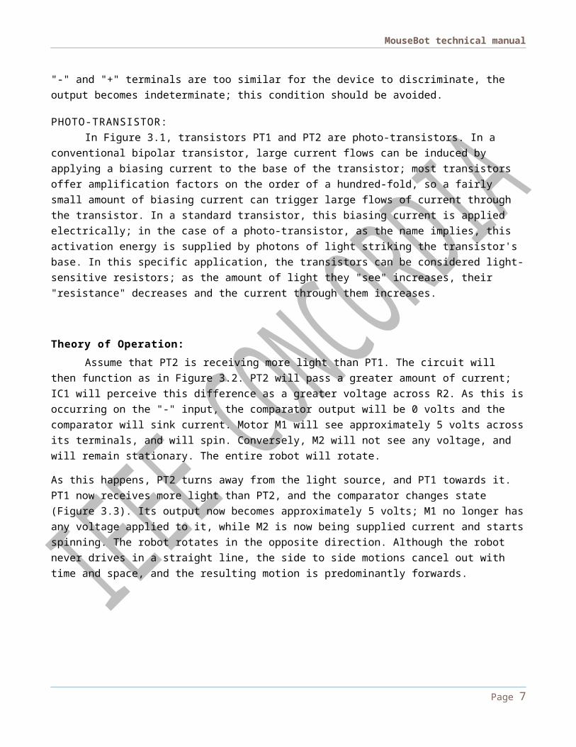
Theory of Operation:Assume that PT2 is receiving more light than PT1. The circuit will then function as in Figure 3.2.
PT2 will pass a greater amount of current; IC1 will perceive this difference as a greater voltage across R2. As this is occurring on the "-" input, the comparator output will be 0 volts and the comparator will sink current. Motor M1 will see approximately 5 volts across its terminals, and will spin. Conversely, M2 will not see any voltage, and will remain stationary. The entire robot will rotate.
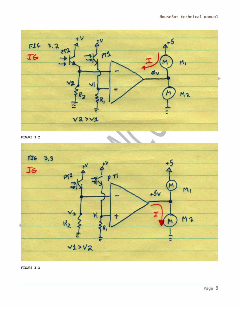
As this happens, PT2 turns away from the light source, and PT1 towards it. PT1 now receives more light than PT2, and the comparator changes state (Figure 3.3). Its output now becomes approximately 5 volts; M1 no longer has any voltage applied to it, while M2 is now being supplied current and starts spinning. The robot rotates in the opposite direction. Although the robot never drives in a straight line, the side to side motions cancel out with time and space, and the resulting motion is predominantly forwards.
FIGURE 3.2
Page 5
MouseBot technical manual
FIGURE 3.3
The power supply system:The MouseBot is designed to operate with energy coming from one of two sources; four AA
batteries and/or a solar panel. The resulting energy can be stored in either a super-capacitor or rechargeable batteries (if installed). Refer to figure 3.4 for a schematic of the power delivery system.
Page 6
MouseBot technical manual
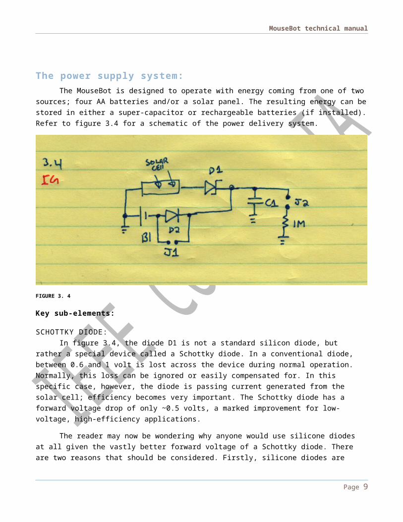
FIGURE 3. 4
Key sub-elements:
SCHOTTKY DIODE:In figure 3.4, the diode D1 is not a standard silicon diode, but rather a special device called a
Schottky diode. In a conventional diode, between 0.6 and 1 volt is lost across the device during normal operation. Normally, this loss can be ignored or easily compensated for. In this specific case, however, the diode is passing current generated from the solar cell; efficiency becomes very important. The Schottky diode has a forward voltage drop of only ~0.5 volts, a marked improvement for low-voltage, high-efficiency applications.
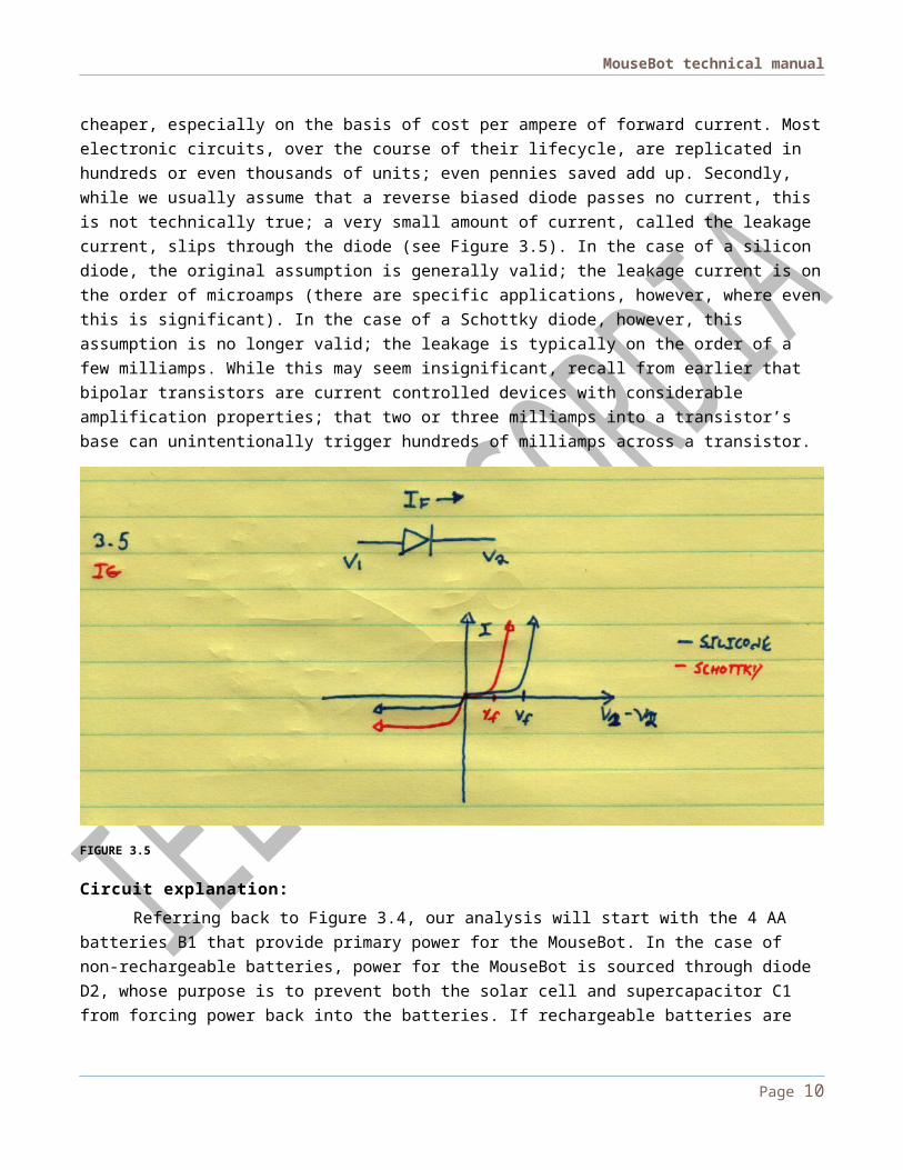
The reader may now be wondering why anyone would use silicone diodes at all given the vastly better forward voltage of a Schottky diode. There are two reasons that should be considered. Firstly, silicone diodes are cheaper, especially on the basis of cost per ampere of forward current. Most electronic circuits, over the course of their lifecycle, are replicated in hundreds or even thousands of units; even pennies saved add up. Secondly, while we usually assume that a reverse biased diode passes no current, this is not technically true; a very small amount of current, called the leakage current, slips through the diode (see Figure 3.5). In the case of a silicon diode, the original assumption is generally valid; the leakage current is on the order of microamps (there are specific applications, however, where even this is significant). In the case of a Schottky diode, however, this assumption is no longer valid; the leakage is typically on the order of a few milliamps. While this may seem insignificant, recall from earlier that bipolar transistors are current controlled devices with considerable amplification properties; that two or three milliamps into a transistor’s base can unintentionally trigger hundreds of milliamps across a transistor.
Page 7
MouseBot technical manual
FIGURE 3.5
Circuit explanation:Referring back to Figure 3.4, our analysis will start with the 4 AA batteries B1 that provide
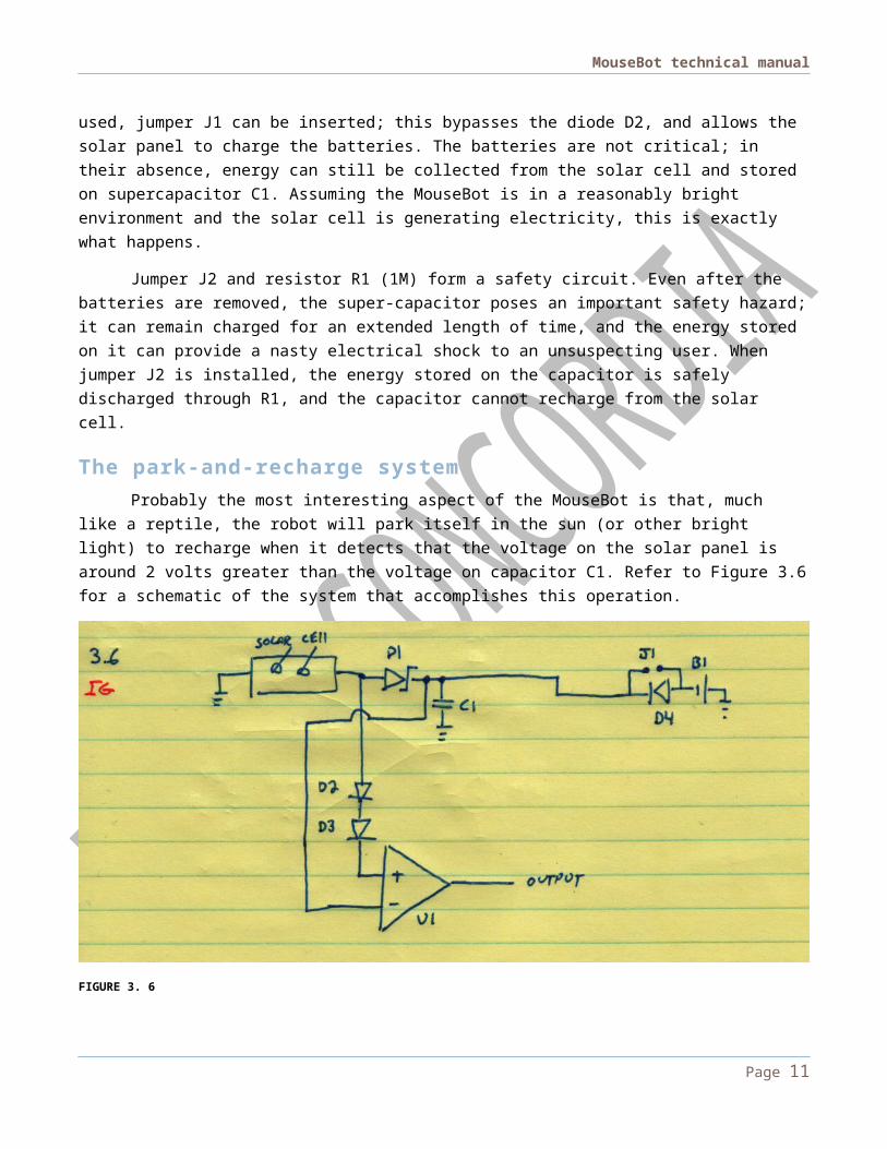
primary power for the MouseBot. In the case of non-rechargeable batteries, power for the MouseBot is sourced through diode D2, whose purpose is to prevent both the solar cell and supercapacitor C1 from forcing power back into the batteries. If rechargeable batteries are used, jumper J1 can be inserted; this bypasses the diode D2, and allows the solar panel to charge the batteries. The batteries are not critical; in their absence, energy can still be collected from the solar cell and stored on supercapacitor C1. Assuming the MouseBot is in a reasonably bright environment and the solar cell is generating electricity, this is exactly what happens.
Jumper J2 and resistor R1 (1M) form a safety circuit. Even after the batteries are removed, the super-capacitor poses an important safety hazard; it can remain charged for an extended length of time, and the energy stored on it can provide a nasty electrical shock to an unsuspecting user. When jumper J2 is installed, the energy stored on the capacitor is safely discharged through R1, and the capacitor cannot recharge from the solar cell.
The park-and-recharge systemProbably the most interesting aspect of the MouseBot is that, much like a reptile, the robot will
park itself in the sun (or other bright light) to recharge when it detects that the voltage on the solar panel is around 2 volts greater than the voltage on capacitor C1. Refer to Figure 3.6 for a schematic of the system that accomplishes this operation.
Page 8
MouseBot technical manual
FIGURE 3. 6
Circuit analysisThe only major additions to the power supply system are D2, D3 and U1. U1 is an op-amp
configured as a comparator, as explained in the drive circuitry above, but it compares the voltage stored on the capacitor against the voltage generated by the solar cell. This circuit would function poorly without D2 and D3: the moment the mouse drove forwards, the voltage on the capacitor would drop and it would immediately stop. What is needed is for the comparator to only change its state when the voltage on the capacitor is less than that on the solar cell by a preset amount. There exist several ways of doing this if a precise voltage drop is needed; we could use a circuit called a Schmitt trigger, which can be designed to set custom values for the low-to-high and high-to-low transition points. Alternatively, we could use an op-amp to perform subtraction. Both of these methods have the advantage of being accurate, at the cost of additional parts and circuit board space, both of which are always at a premium. In this specific application, a much simpler solution exists; recall that in the section on Schottky diodes, it was mentioned that conventional silicone diodes drop between 0.7 and 1.0 volt per diode; by simply putting two in series, we can create the necessary voltage drop (1.4 to 2.0V). This is the role of D2 and D3.
The reader may be interested to learn why a simple resistor cannot be used in this application; the answer lies in the very high input impedance of the op-amp. Functionally, the op-amp's input can be thought of as an open circuit in this application. No current is flowing into it, and hence no current is flowing through the resistor, so no voltage drop will evolve on the resistor.
Full circuit analysis:Let us now consider the entire MouseBot circuit, as show in Figure 3.7. Much of it consists of
the sub-circuits we have examined previously.
Page 9
MouseBot technical manual
FIGURE 3.7
Page 10
MouseBot technical manual
Circuit analysis:There are two important additions to the circuit above from the sub-circuits examined previously.
First, there is the addition of an LED circuit at the bottom of Figure 3.7. This circuit, when the jumper is installed, shines infrared light from the back of the MouseBot. As other MouseBot's photo-transistors are especially sensitive to the near-IR spectrum, any other 'bots will attempt to chase the one with its LED turned on. Thus, several mice can play together.
The more significant additions revolve around the two MOSFETs (a type of transistor) connected on either side of the drive motors, and the second LM358 op-amp. The purpose of the MOSFETs is to cut off current to the drive motors when the park-and-recharge system detects the MouseBot is in a bright spot. However, the two MOSFETs are different types: the top MOSFET (near M1) turns off when voltage is applied, while the bottom MOSFET turns on under those same conditions, thus the need for the extra op-amp. It is connected as a unity gain inverter; whatever signal appears at its input, the opposite will appear at the output.
When the system detects that the robot is good to drive, the comparator output is a “0”, turning on the top MOSFET. The inverter output is a “1”, turning on the bottom MOSFET. When the system decides to stop and recharge, the outputs switch state.
Page 11